
IBM_Storwize_v3700_part2.3814267D76D04E9BBD3FE736EC255841
167
© Copyright IBM Corp. 2012. All rights reserved. 135 Draft Document for Review February 27, 2013 3:34 pm 8107 04 Host config NANCY IMRAN.fm Host configuration This chapter describes how to use the IBM Storwize V3700 GUI to create hosts, and how to prepare a host to access the volumes that are created. (Volume creation is described in Chapter 5, “Basic volume configuration” on page 163.) 4
-
Upload
raul-sarango -
Category
Documents
-
view
29 -
download
5
Transcript of IBM_Storwize_v3700_part2.3814267D76D04E9BBD3FE736EC255841

© Copyright IBM Corp. 2012. All rights reserved. 135
Draft Document for Review February 27, 2013 3:34 pm 8107 04 Host config NANCY IMRAN.fm
Chapter 4. Host configuration
This chapter describes how to use the IBM Storwize V3700 GUI to create hosts, and how to prepare a host to access the volumes that are created. (Volume creation is described in Chapter 5, “Basic volume configuration” on page 163.)
4

8107 04 Host config NANCY IMRAN.fm Draft Document for Review February 27, 2013 3:34 pm
136 Storwize V3700 Implementation
4.1 Host attachment overview
A host system is an open-systems computer that is connected to the switch through a Fibre Channel or an iSCSI interface.
This chapter describes the following topics:
� Preparing the host operating system– Windows
• Fibre Channel (FC)• iSCSI
– VMware• Fibre Channel• iSCSI
� Creating hosts using the Storwize V3700 GUI– Creating FC hosts– Creating iSCSI hosts
In this chapter, we assume that your hosts are connected to your FC or IP network and you have completed the steps described in 2.9, “Initial configuration” on page 42. Follow basic zoning recommendations to ensure that each host has at least two network adapters, that each adapter is on a separate network (or at minimum in a separate zone), and is connected to both canisters. This setup assures four paths for failover and failback purposes.
Before mapping the newly created volumes on the host of your choice, a little preparation goes a long way towards ease of use and reliability. There are several steps required on a host in preparation for mapping new IBM Storwize V3700 volumes to the host. Use the System Storage Interoperation Center (SSIC) to check which code levels are supported to attach your host to your storage. SSIC is a web tool that checks the interoperation of host, storage, switches, and multipathing drivers. It can be found at the following address:
http://ibm.com/systems/support/storage/ssic/interoperability.wss
The complete support matrix is listed in the IBM Storwize V3700 Supported Hardware List, Device Driver, Firmware, and Recommended Software Levels V6.4 document, which is available at the following address:
http://www-01.ibm.com/support/docview.wss?uid=ssg1S1004111
This chapter focuses on Windows and VMWare. If you must attach any other hosts, for example, IBM AIX®, Linux, or even an Apple system, then you can find the required information in the IBM Storwize V3700 Information Center at the following address:
http://pic.dhe.ibm.com/infocenter/storwize/v3700_ic/index.jsp

Chapter 4. Host configuration 137
Draft Document for Review February 27, 2013 3:34 pm 8107 04 Host config NANCY IMRAN.fm
4.2 Preparing the host operating system
In this section, we describe how to prepare Windows and VMware hosts for attachment to an IBM Storwize V3700, using either Fibre Channel or iSCSI to connect.
4.2.1 Windows 2008 (R2): Preparing for Fibre Channel attachment
Complete the following steps to prepare a Windows 2008 (R2) host to connect to an IBM Storwize V3700 using Fibre Channel:
1. Make sure that the latest OS service pack and test fixes are applied to your Microsoft server.
2. Use the latest firmware and driver levels on your host system.
3. Install HBA or HBAs on the Windows server using the latest BIOS and drivers.
4. Connect the FC Host Adapter ports to the switches.
5. Configure the switches (zoning).
6. Configure the HBA for hosts running Windows.
7. Set the Windows timeout value.
8. Install the multipath module.
Downloading and installing the supported drivers and firmwareInstall a supported HBA driver for your configuration. Use the Windows Device Manager or vendor tools such as Sansurfer (QLogic), HBAnyware (Emulex), or HBA Software Installer (Brocade) to install the driver. Also check and update the BIOS (firmware) level of the HBA using the manufacturer’s provided tools. Check the readme file to see if there are Windows registry parameters that should be set for the HBA driver.
The latest supported levels are available at the following address:
http://ibm.com/support/docview.wss?uid=ssg1S1003703#_Win2008
Configuring Brocade HBAs for WindowsThis section applies to Windows hosts that have Brocade HBAs installed. After installing the device driver and firmware, you must configure the HBAs. To perform this task, either use the Brocade HCM software or reboot into the HBA BIOS, load the adapter defaults, and set the following values:
� Host Adapter BIOS: Disabled (unless the host is configured for SAN Boot)� Queue depth: 4
Configuring QLogic HBAs for WindowsThis section applies to Windows hosts that have QLogic HBAs installed.
After installing the device driver and firmware, you must configure the HBAs. To perform this task, either use the QLogic Sansurfer software or reboot into the HBA BIOS, load the adapter defaults, and set the following values:
� Host Adapter BIOS: Disabled (unless the host is configured for SAN Boot)� Adapter Hard Loop ID: Disabled� Connection Options: 1 - point to point only� LUNs Per Target: 0� Port Down Retry Count: 15

8107 04 Host config NANCY IMRAN.fm Draft Document for Review February 27, 2013 3:34 pm
138 Storwize V3700 Implementation
Configuring Emulex HBAs for WindowsThis section applies to Windows hosts that have Emulex HBAs installed.
After installing the device driver and firmware, you must configure the HBAs. To perform this task, either use the Emulex HBAnyware software or reboot into the HBA BIOS, load the defaults, and set topology to 1 (10F_Port Fabric).
Setting the Windows timeout valueFor Windows hosts, the disk I/O timeout value should be set to 60 seconds. To verify this setting, complete the following steps:
1. Click Start Run.
2. In the dialog box, type regedit and press Enter.
3. In the registry editor, locate the HKEY_LOCAL_MACHINE\System\CurrentControlSet\Services\Disk\TimeOutValue key.
4. Confirm that the value for the key is 60 (decimal value), and, if necessary, change the value to 60 (Figure 4-1).
Figure 4-1 Windows timeout value
Installing the multipathing softwareMicrosoft Multipath Input/Output (MPIO) solutions are designed to work with device-specific modules (DSMs) written by vendors, but the MPIO driver package does not, by itself, form a complete solution. This joint solution allows the storage vendors to design device-specific solutions that are tightly integrated with the Windows operating system. MPIO is not shipped with the Windows operating system; storage vendors must pack the MPIO drivers with their own DSM.
IBM Subsystem Device Driver DSM (SDDDSM) is the IBM multipath I/O solution that is based on Microsoft MPIO technology. It is a device-specific module designed to support IBM storage devices on Windows hosts. The intent of MPIO is to provide better integration of a multipath storage solution with the operating system, and it allows the use of multipath in the SAN infrastructure during the boot process for SAN Boot hosts.
To ensure correct multipathing with IBM Storwize V3700, SDDDSM must be installed on Windows hosts. To install SDDDSM, complete the following steps:
1. Check the SDDDSM download matrix to determine the correct level of SDDDSM to install for Windows 2008 (R2) and download the package from the following address:
http://ibm.com/support/docview.wss?uid=ssg1S7001350#WindowsSDDDSM
2. Extract the package to your hard disk drive and run setup.exe to install SDDDSM. A command prompt window opens (Figure 4-2). Confirm the installation by entering Y.

Chapter 4. Host configuration 139
Draft Document for Review February 27, 2013 3:34 pm 8107 04 Host config NANCY IMRAN.fm
Figure 4-2 SDDDSM setup
3. After the setup completes, you are prompted to restart the system. Confirm this restart by typing yes and pressing Enter (Figure 4-3).
Figure 4-3 Answer yes to restart the host
You have now successfully installed IBM SDDDSM. You can check the installed driver version if you select Start All Programs Subsystem Device Driver DSM Subsystem Device Driver DSM. A command prompt opens; run datapath query version to determine the version currently installed (Example 4-1) for this Windows 2008 R2 host.
Example 4-1 datapath query version
C:\Program Files\IBM\SDDDSM>datapath.exe query versionIBM SDDDSM Version 2.4.3.1-2Microsoft MPIO Version 6.1.7601.17514
This command can also be used to determine the WWPNs of the host. Run datapath query wwpn (Example 4-2) and note the WWPNs of your host, as you need them later.
Example 4-2 datapath query wwpn
C:\Program Files\IBM\SDDDSM>datapath.exe query wwpn Adapter Name PortWWN Scsi Port 7 100000051EC76B89 Scsi Port 7 100000051EC76B8A
If you need more detailed information about SDDDSM, see Multipath Subsystem Device Driver User’s Guide, GC52-1309.

8107 04 Host config NANCY IMRAN.fm Draft Document for Review February 27, 2013 3:34 pm
140 Storwize V3700 Implementation
The Windows host has been prepared to connect to the IBM Storwize V3700 and you know the WWPNs of the host. The next step is to configure a host object for the WWPNs by using the IBM Storwize V3700 GUI. This task is explained in 4.3.1, “Creating Fibre Channel hosts” on page 151.
SAN Boot hosts are beyond the intended scope of this book. For more information about that topic, follow the steps in the Information Center available from the IBM Support Portal.
4.2.2 Windows 2008 R2: Preparing for iSCSI attachment
In Windows 2008 R2, the Microsoft iSCSI software initiator is preinstalled. Enter iscsi in the search field of the Windows start menu (Figure 4-4) and click iSCSI Initiator.
Figure 4-4 Windows iSCSI Initiator
Confirm the automatic startup of the iSCSI Service (Figure 4-5).
Figure 4-5 Automatic startup of the iSCSI Service
Windows 2003: The examples focus on Windows 2008 R2, but the procedure for Windows 2003 is similar. If you use Windows 2003, do not forget to install Microsoft Hotfix 908980. If you do not install it before performing this procedure, preferred pathing is not available. You can download this hotfix at the following address:
http://support.microsoft.com/kb/908980

Chapter 4. Host configuration 141
Draft Document for Review February 27, 2013 3:34 pm 8107 04 Host config NANCY IMRAN.fm
The iSCSI Configuration window opens. Select the Configuration tab (Figure 4-6). Write down the initiator name of your Windows host, as you need it later.
Figure 4-6 iSCSI Initiator Properties window
You can change the initiator name, or enable advanced authentication, but these actions are out of the scope of our basic setup; by default, iSCSI authentication is not enabled. More detailed information is available in the IBM Storwize V3700 Information Center at the following address:
http://pic.dhe.ibm.com/infocenter/storwize/v3700_ic/index.jsp?topic=%2Fcom.ibm.storwize.v3700.641.doc%2Fsvc_iscsi_cover.html

8107 04 Host config NANCY IMRAN.fm Draft Document for Review February 27, 2013 3:34 pm
142 Storwize V3700 Implementation
Setting the Windows registry keysYou should make the following changes to the system registry to make your iSCSI operations more reliable:
1. In the search field of the Windows Start menu, type regedit and click regedit.exe.
2. In the registry editor, locate the key HKEY_LOCAL_MACHINE\SYSTEM\CurrentControlSet\Control\Class\{4D36E97B-E325-11CE-BFC1-08002BE10318}\<bus ID>\Parameters\LinkDownTime.
Confirm that the value for the LinkDownTime key is 120 (decimal value), and, if necessary, change the value to 120.
3. In the registry editor, locate the HKEY_LOCAL_MACHINE\SYSTEM\CurrentControlSet\Control\Class\{4D36E97B-E325-11CE-BFC1-08002BE10318}\<bus ID>\Parameters\MaxRequestHoldTime key.
Confirm that the value for the MaxRequestHoldTime key is 120 (decimal value), and, if necessary, change the value to 120.
4. In the registry editor, locate the HKEY_LOCAL_MACHINE\SYSTEM\CurrentControlSet\Control\Class\{4D36E97B-E325-11CE-BFC1-08002BE10318}\<bus ID>\Parameters\ MaxPendingRequests key.
Confirm that the value for the MaxPendingRequests key is 2048 (decimal value), and, if necessary, change the value to 2048.
5. In the registry editor, locate the HKEY_LOCAL_MACHINE\SYSTEM\CurrentControlSet\Services\Disk\TimeOutValue key.
Confirm that the value for the TimeOutValue key is 60 (decimal value), and, if necessary, change the value to 60.
6. Reboot your host for these changes to take effect.
These steps are the basic steps to prepare a Windows 2008 R2 host for iSCSI attachment. To configure the IBM Storwize V3700 for iSCSI connections, see 4.3.2, “Creating iSCSI hosts” on page 155.
4.2.3 VMware ESX: Preparing for Fibre Channel attachment
Complete the following steps to prepare a VMware ESXi host to connect to an IBM Storwize V3700 using Fibre Channel:
1. Install HBA or HBAs on the ESXi server.2. Make sure that the latest firmware levels are applied on your host system.3. Update and configure the HBA for hosts running ESXi.4. Connect the FC Host Adapter ports to the switches.5. Configure the switches (zoning).6. Install VMware ESXi and load additional drivers if required.
Downloading and installing the supported firmwareInstall the latest firmware levels to your host server. For the HBAs, check the “IBM Storwize V3700 Supported Hardware List, Device Driver, Firmware, and Recommended Software Levels V6.4” list for VMware at the following address:
http://www-01.ibm.com/support/docview.wss?uid=ssg1S1004111#_VMWare

Chapter 4. Host configuration 143
Draft Document for Review February 27, 2013 3:34 pm 8107 04 Host config NANCY IMRAN.fm
Download the latest supported HBA firmware for your configuration and apply it to your system. Some HBAs and especially the new CNA Adapters require an additional driver to be loaded into ESX. Check the VMware Compatibility Guide to see if there are any requirements for your configuration by going to the following address:
http://www.vmware.com/resources/compatibility/search.php
Configuring Brocade HBAs for VMware ESXThis section applies to ESXi hosts that have Brocade HBAs installed. After installing the firmware, load the default settings of all your adapters installed on the host system and make sure that the Adapter BIOS is disabled, unless you are using SAN Boot.
Configuring QLogic HBAs for VMware ESXThis section applies to ESXi hosts that have QLogic HBAs installed. After installing the firmware, you must configure the HBAs. To perform this task, either use the QLogic Sansurfer software or the HBA BIOS, load the adapter defaults, and set the following values:
� Host Adapter Settings:– Host Adapter BIOS: Disabled (unless the host is configured for SAN Boot)– Frame size: 2048– Loop Reset Delay: 5 (minimum)– Adapter Hard Loop ID: Disabled– Hard Loop ID: 0– Spinup Delay: Disabled– Connection Options 1: Point to point only– Fibre Channel Tape Support: Disabled– Data Rate: 2
� Advanced Adapter Settings– Execution throttle: 100– LUNs per Target: 0– Enable LIP Reset: No– Enable LIP Full Login: Yes– Enable Target Reset: Yes– Login Retry Count: 8– Link Down Timeout: 10– Command Timeout: 20– Extended event logging: Disabled (only enable it for debugging)– RIO Operation Mode: 0– Interrupt Delay Timer: 0
Configuring Emulex HBAs for VMware ESXiThis section applies to ESXi hosts that have Emulex HBAs installed. After installing the firmware, load the default settings of all your adapters installed on the host system and make sure that the Adapter BIOS is disabled, unless you are using SAN Boot.
VMware ESXi installationInstall your VMware ESXi server and load any additional drivers and patches if required. If you are not familiar with the procedure, you can find a detailed installation guide at the following address:
http://pubs.vmware.com/vsphere-50/topic/com.vmware.ICbase/PDF/vsphere-esxi-vcenter-server-50-storage-guide.pdf

8107 04 Host config NANCY IMRAN.fm Draft Document for Review February 27, 2013 3:34 pm
144 Storwize V3700 Implementation
After you have completed your ESXi installation, connect to your ESXi Server using the vSphere client and navigate to the Configuration tab, click Storage Adapters, and scroll down to your FC HBAs (Figure 4-7). Note the WWPNS of the installed adapters for later use.
Figure 4-7 Show WWPNs in VMware ESX
VMware ESXi multipathingThe ESXi server has its own multipathing software. You do not need to install a multipathing driver, either on the ESXi server or on the guest operating systems. The ESXi multipathing policy supports three operating modes:
� Round Robin� Fixed� Most Recently Used (MRU)
The IBM Storwize V3700 is an active / active storage device. Since VMware ESXi 5.0 and later, the suggested multipathing policy is Round Robin. Round Robin performs static load balancing for I/O. If you do not want to have the I/O balanced over all available paths, the Fixed policy is supported as well. This policy setting can be selected for every volume. Set this policy after attaching IBM Storwize V3700 LUNs to the ESXi host after reading 4.2.3, “VMware ESX: Preparing for Fibre Channel attachment” on page 142 for information. If you use an older version of VMware ESX (up to Version 3.5), Fixed is the recommended policy setting.
After all these steps are completed, the ESXi host is prepared to connect to the IBM Storwize V3700. Go to 4.3.1, “Creating Fibre Channel hosts” on page 151 to create the ESX FC host in the IBM Storwize V3700 GUI.

Chapter 4. Host configuration 145
Draft Document for Review February 27, 2013 3:34 pm 8107 04 Host config NANCY IMRAN.fm
4.2.4 VMware ESX: Preparing for iSCSI attachment
This section describes how to enable iSCSI on VMware ESX hosts. In this book, we focus on vSphere (ESXi 5.0 and later) because the complete iSCSI stack has been updated in this level to offer improved performance, and supports useful features, such as jumbo frames and increased numbers of switches supported per server and doubles the number of port groups supported per server. we will focus on the basic ESXi iSCSI setup; more detailed information is provided in the VMware iscsi san configuration guide, which is available at the following address:
http://pubs.vmware.com/vsphere-50/topic/com.vmware.icbase/pdf/vsphere-esxi-vcenter-server-50-storage-guide.pdf
Complete the following steps to prepare a VMware ESXi host to connect to an IBM Storwize V3700 using iSCSI:
1. Make sure that the latest firmware levels are applied on your host system.
2. Install VMware ESXi and load additional drivers if required.
3. Connect the ESXi server to your network. You should use separate network interfaces for iSCSI traffic.
4. Configure your network to fulfill your security and performance requirements.
The iSCSI initiator is installed by default on your ESXi server, and you only have to enable it. To enable it, complete the following steps:
1. Connect to your ESXi server using the vSphere Client, navigate to Configuration, and select Networking (Figure 4-8).
Figure 4-8 Select VMware networking
2. Click Add Networking to start the Add Network Wizard (Figure 4-9 on page 146). Select VMkernel and click Next.

8107 04 Host config NANCY IMRAN.fm Draft Document for Review February 27, 2013 3:34 pm
146 Storwize V3700 Implementation
Figure 4-9 VMware - Add Network Wizard
3. Select one or more network interfaces that you want to use for iSCSI traffic and click Next (Figure 4-10).
Note: The VMkernel performs the virtualization and is also referred as the hypervisor.

Chapter 4. Host configuration 147
Draft Document for Review February 27, 2013 3:34 pm 8107 04 Host config NANCY IMRAN.fm
Figure 4-10 VMware - Select an iSCSI interface
4. Enter a meaningful Network Label and click Next (Figure 4-11).
Figure 4-11 VMware - Enter a Network Label

8107 04 Host config NANCY IMRAN.fm Draft Document for Review February 27, 2013 3:34 pm
148 Storwize V3700 Implementation
5. Enter an IP address for your iSCSI network. You should use a dedicated network for iSCSI traffic (Figure 4-12).
Figure 4-12 VMware - Enter iSCSI Network IP
6. Click Finish to complete the setup.
7. Select Storage Adapters and scroll down to iSCSI Software Adapter (Figure 4-13). Highlight it and click Properties.

Chapter 4. Host configuration 149
Draft Document for Review February 27, 2013 3:34 pm 8107 04 Host config NANCY IMRAN.fm
Figure 4-13 VMware - iSCSI Software Adapter
8. The iSCSI Software Adapter Properties window opens. As you can see in Figure 4-14, the initiator is enabled (changed from VMWare ESX 4.0) by default; if you wanted to change this setting, click Configure.
Figure 4-14 VMware - iSCSI Software Adapter Properties

8107 04 Host config NANCY IMRAN.fm Draft Document for Review February 27, 2013 3:34 pm
150 Storwize V3700 Implementation
9. The VMware ESX iSCSI initiator is now successfully enabled (Figure 4-15). Note the initiator name for later use.
Figure 4-15 VMware iSCSI Initiator enabled
Your VMware ESX host is now prepared to connect to the IBM Storwize V3700. Go to 4.3.2, “Creating iSCSI hosts” on page 155 to create the ESX iSCSI host using the IBM Storwize V3700 GUI.
4.3 Creating hosts using the GUI
This section describes how to create Fibre Channel and iSCSI hosts using the IBM Storwize V3700 GUI. We assume that the hosts are prepared for attachment, as described in 4.2, “Preparing the host operating system” on page 137, and that you know the host WWPNs and their iSCSI initiator names.
To create a host, complete the following steps:
1. Open the host configuration window by clicking Hosts (Figure 4-16).

Chapter 4. Host configuration 151
Draft Document for Review February 27, 2013 3:34 pm 8107 04 Host config NANCY IMRAN.fm
Figure 4-16 Open the host window
2. To create a host, click New Host to start the wizard (Figure 4-17).
Figure 4-17 Create a host
If you want to create a Fibre Channel host, continue with 4.3.1, “Creating Fibre Channel hosts” on page 151; to create iSCSI hosts, go to 4.3.2, “Creating iSCSI hosts” on page 155.
4.3.1 Creating Fibre Channel hosts
To create Fibre Channel hosts, complete the following steps:
1. Click Fibre Channel Host (Figure 4-17 on page 151). The Fibre Channel configuration wizard opens (Figure 4-18).

8107 04 Host config NANCY IMRAN.fm Draft Document for Review February 27, 2013 3:34 pm
152 Storwize V3700 Implementation
Figure 4-18 Create a Fibre Channel host
2. Enter a host name and click the Fibre Channel Ports drop-down menu to get a list of all known WWPNs (Figure 4-19).
Figure 4-19 Available WWPNs
The IBM Storwize V3700 has the host port WWPNs available if you prepared the hosts, as described in 4.2, “Preparing the host operating system” on page 137. If they do not appear in the list, scan for new disks in your operating system and click Rescan in the configuration wizard. If they still do not appear, check your SAN zoning and repeat the scanning. For more detail on hosts please refer to the infocenter at this link:
http://pic.dhe.ibm.com/infocenter/storwize/v3700_ic/index.jsp?topic=%2Fcom.ibm.storwize.v3700.641.doc%2Fsvc_fibrechannel_cover.html
l
3. Select the WWPN for your host and click Add Port to List (Figure 4-20).
AIX HOSTS: AIX hosts WWPNs will only will only appear for a few minutes after logging into the fabric. You can either type in the WWPN into the drop down manually, or you will need to run the cfgmgr again to allow the host to login to the fabric and be discovered into the GUI.

Chapter 4. Host configuration 153
Draft Document for Review February 27, 2013 3:34 pm 8107 04 Host config NANCY IMRAN.fm
Figure 4-20 Add a port to a list
4. Add all ports that belong to the host (Figure 4-21).
Figure 4-21 Add all WWPNs
5. If you are creating an HP/UX or TPGS host, select the Advanced check box and more options appear (Figure 4-22). Select your host type.
Creating offline hosts: If you want to create hosts that are offline, or not connected at the moment, it is also possible to enter the WWPNs manually. Type them into the Fibre Channel Ports Box and add them to the list as well.

8107 04 Host config NANCY IMRAN.fm Draft Document for Review February 27, 2013 3:34 pm
154 Storwize V3700 Implementation
Figure 4-22 Create Host - Advanced Settings
6. Click Create Host and the wizard creates the host (Figure 4-23).
Figure 4-23 Create Host completes
7. Click Close to return to the host window (Figure 4-24).

Chapter 4. Host configuration 155
Draft Document for Review February 27, 2013 3:34 pm 8107 04 Host config NANCY IMRAN.fm
Figure 4-24 All Hosts
8. Repeat these steps for all of your Fibre Channel hosts. Figure 4-25 shows the All Hosts window after creating a second host.
Figure 4-25 All Hosts - After creating a second host
After you complete the creation of Fibre Channel hosts, go to Chapter 5, “Basic volume configuration” on page 163 to create volumes and map them to the created hosts.
4.3.2 Creating iSCSI hosts
To create iSCSI hosts, complete the following steps:
1. Click iSCSI Host (Figure 4-17 on page 151) and the iSCSI configuration wizard opens (Figure 4-26).

8107 04 Host config NANCY IMRAN.fm Draft Document for Review February 27, 2013 3:34 pm
156 Storwize V3700 Implementation
Figure 4-26 Create an iSCSI host
2. Enter a host name, type the iSCSI initiator name into the iSCSI Ports box, and click Add Ports to List (Figure 4-27 on page 156). If you want to add several initiator names to one host, repeat this step.
Figure 4-27 Create an iSCSI host - Enter name and iSCSI ports
3. If you are connecting an HP/UX or TPGS host, select the Advanced check box (Figure 4-28) and select the correct host type.

Chapter 4. Host configuration 157
Draft Document for Review February 27, 2013 3:34 pm 8107 04 Host config NANCY IMRAN.fm
Figure 4-28 Create an iSCSI host - Advanced Settings
4. Click Create Host and the wizard completes (Figure 4-29). Click Close.
Figure 4-29 Create an iSCSI host - Complete
5. Repeat these steps for every iSCSI host you want to create.
The iSCSI hosts are now configured on the IBM Storwize V3700. To provide connectivity, the iSCSI Ethernet ports also must be configured. Complete the following steps to enable iSCSI connectivity:
6. Switch to the Configuration window and select Network as shown in Figure 4-30 on page 158.

8107 04 Host config NANCY IMRAN.fm Draft Document for Review February 27, 2013 3:34 pm
158 Storwize V3700 Implementation
Figure 4-30 Configuration - Network
7. Select iSCSI and the iSCSI Configuration window opens (Figure 4-31).
Figure 4-31 iSCSI Configuration window

Chapter 4. Host configuration 159
Draft Document for Review February 27, 2013 3:34 pm 8107 04 Host config NANCY IMRAN.fm
In the configuration, you have an overview of all the iSCSI settings for the IBM Storwize V3700. You can configure iSCSI Alias, iSNS Addresses, and Chap Authentication Configuration on this window, and the iSCSI IP address, which we also edit in the basic setup.
8. Click within the Ethernet Ports and choose left or right to enter the iSCSI IP address (Figure 4-32). Repeat this step for each port you want to use for iSCSI traffic.
Figure 4-32 Enter an iSCSI IP address
9. After you have entered the IP address for each port, click Save Changes to enable the configuration (Figure 4-33).
Figure 4-33 iSCSI IP configuration
Before your ESXi host can discover Storwize V3700 storage, the iSCSI initiator must be configured and authentication might have to be done.

8107 04 Host config NANCY IMRAN.fm Draft Document for Review February 27, 2013 3:34 pm
160 Storwize V3700 Implementation
You can verify the network configuration by using the vmkping utility. If you need to authenticate the target you may need to configure the dynamic discovery address and target name of the Storwize V3700 in vSphere as shown in Figure 4-34.
Figure 4-34 iSCSI Dynamic Discovery
Choose to Add Send Target Server as shown in Figure 4-35 on page 160.
Figure 4-35 iSCSI add Target
Give the IP address of the target (Figure 4-36). The target IP address is the IP address of a node in the I/O group from which you are mapping the iSCSI volume.

Chapter 4. Host configuration 161
Draft Document for Review February 27, 2013 3:34 pm 8107 04 Host config NANCY IMRAN.fm
Figure 4-36 Add iSCSI IP of Target
Leave the IP port number at the default value of 3260. The connection between the initiator and target is established after clicking OK. Repeat this process for each target IP. Once these are entered and you close out of the dialog box, you will be prompted to rescan the host bus adapters as shown in Figure 4-37. The maximum number of volumes that can be mapped to the VMware iSCSI initiator is 256.
Figure 4-37 Rescan of host bus adapters
The IBM Storwize V3700 is now configured and ready for iSCSI use. Note the initiator names of your storage canisters (Figure 4-31 on page 158), as you need them later. Go to Chapter 5, “Basic volume configuration” on page 163 to create volumes and map them to a host.
Note: iSNS discovery is not supported in VMware ESX 4.

8107 04 Host config NANCY IMRAN.fm Draft Document for Review February 27, 2013 3:34 pm
162 Storwize V3700 Implementation

© Copyright IBM Corp. 2012. All rights reserved. 163
Draft Document for Review February 27, 2013 3:34 pm 8107 05 VOLUME CONFIGURATION IMRAN DIETER.fm
Chapter 5. Basic volume configuration
This chapter describes how to use the IBM Storwize V3700 to create a volume and map a volume to a host. A volume is a logical disk on the IBM Storwize V3700 that is provisioned out of a storage pool and is recognized by a host with an identifier UID field and a parameter list.
The first part of the chapter describes how to create volumes of different types and map them to the defined host.
The second part of this chapter covers how to discover those volumes (5.1, “Provisioning storage from IBM Storwize V3700 and making it available to the host” on page 164). After you finish this chapter, your basic configuration is done and you are able to store data on the IBM Storwize V3700.
Advanced host and volume administration, such as adding and deleting host ports, creating flash copy, and so on, is described in Chapter 8, “Advanced host and volume administration” on page 303.
5

8107 05 VOLUME CONFIGURATION IMRAN DIETER.fm Draft Document for Review February 27, 2013 3:34 pm
164 Storwize V3700 Implementation
5.1 Provisioning storage from IBM Storwize V3700 and making it available to the host
This section follows the setup process and shows how to create volumes and make them accessible from the host. The following steps are required to complete the basic setup of your environment:
1. Create new volumes.
2. Map volumes to the host (see 5.2, “Mapping a volume to the host” on page 176 for more information).
3. Discover the volumes from the host and specify multipath settings (see 5.3, “Discovering the volumes from the host and specifying multipath settings” on page 180 for more information).
Open the All Volumes window of the IBM Storwize V3700 GUI (Figure 5-1) to start the process of creating new volumes.
Figure 5-1 Home window

Chapter 5. Basic volume configuration 165
Draft Document for Review February 27, 2013 3:34 pm 8107 05 VOLUME CONFIGURATION IMRAN DIETER.fm
The All Volumes window opens (Figure 5-2).
Figure 5-2 All Volumes window
At the moment, you have not created any volumes, so click New Volume button (Figure 5-3).
Figure 5-3 New Volume Button
The New Volume window opens (Figure 5-4).

8107 05 VOLUME CONFIGURATION IMRAN DIETER.fm Draft Document for Review February 27, 2013 3:34 pm
166 Storwize V3700 Implementation
Figure 5-4 New Volume Window
By default, all volumes that you create are striped across all available MDisks in one storage pool. The GUI for the IBM Storwize V3700 provides the following preset selections for the user:
� Generic: A striped volume that is fully provisioned, as described in 5.1.1, “Creating a generic volume” on page 166.
� Thin-provisioned: A striped volume that is space efficient. There are choices under the Advanced button to help determine how much space is fully allocated initially and how large the volume is able to grow, as described in 5.1.2, “Creating a thin-provisioned volume” on page 168.
� Mirror: A striped volume that consists of two striped copies and is synchronized to protect against loss of data if the underlying storage pool of one copy is lost, as described in 5.1.3, “Creating a mirrored volume” on page 171.
� Thin-mirror: Two synchronized copies. Both are thin provisioned, as described in 5.1.4, “Creating a thin-mirror volume” on page 174.
Select which volume you want to create and go to the relevant section.
5.1.1 Creating a generic volume
The most commonly used type of volume is the generic volume type. This type of volume is fully provisioned, with the entire size of the volume dedicated to the volume. The host and the IBM Storwize V3700 see the fully allocated space without a mirror.
We choose a generic volume (Figure 5-4 on page 166) and then we select the pool in which the volume should be created. Select the pool by clicking it. In our example, we click pool called mdiskgrp0. The result is shown in Figure 5-5.

Chapter 5. Basic volume configuration 167
Draft Document for Review February 27, 2013 3:34 pm 8107 05 VOLUME CONFIGURATION IMRAN DIETER.fm
Figure 5-5 Create a generic volume
Note: The “Create and Map to Host” button will be disabled if no host is already configured on the IBM Storwize V3700, follow the instructions on Chapter 4, “Host configuration” on page 135.

8107 05 VOLUME CONFIGURATION IMRAN DIETER.fm Draft Document for Review February 27, 2013 3:34 pm
168 Storwize V3700 Implementation
Enter a volume name and a size, and click Create and Map to Host. The new Generic Volume is created (Figure 5-6). Click Continue and go to 5.2.1, “Mapping newly created volumes to the host using the wizard” on page 176.
Figure 5-6 Volume created
If you do not want to map the volumes now, click Create (Figure 5-5 on page 167) to complete the task. Volumes can also be mapped later, as described in 5.2.2, “Manually mapping a volume to the host” on page 178.
5.1.2 Creating a thin-provisioned volume
Volumes can be configured to be thin provisioned. A thin-provisioned volume behaves with respect to application reads and writes as though they were fully allocated. When creating a thin-provisioned volume, it is possible to specify two capacities: the real physical capacity allocated to the volume from the storage pool and its virtual capacity available to the host. So the real capacity determines the quantity of extents that are initially allocated to the volume. The virtual capacity is the capacity of the volume reported to all other components (for example, FlashCopy and cache) and to the host servers.

Chapter 5. Basic volume configuration 169
Draft Document for Review February 27, 2013 3:34 pm 8107 05 VOLUME CONFIGURATION IMRAN DIETER.fm
To create a thin-provisioned volume, complete the following steps:
1. Select Thin-Provision (Figure 5-7).
Figure 5-7 Create a thin-provisioned volume
2. Select the pool in which the thin-provisioned volume should be created by clicking it and entering the volume name and size. In our example, we click pool called mdiskgrp0. The result is shown in Figure 5-8.
Figure 5-8 Enter the volume name and size

8107 05 VOLUME CONFIGURATION IMRAN DIETER.fm Draft Document for Review February 27, 2013 3:34 pm
170 Storwize V3700 Implementation
Under the Volume Name field is a summary showing that you are about to make a thin-provisioned volume, how much virtual space will be available, the space that will be allocated (real size), and the free capacity in the pool. By default, the real capacity is 2% of the virtual capacity; you can change this setting by clicking Advanced.
Figure 5-9 Advanced Settings
On the Thin Provisioning tab (Figure 5-9), there are several advanced options available:
– Real: Specify the size of the real capacity space used during creation.
– Automatically Extend: This option enables the automatic expansion of real capacity, if new capacity must be allocated.
– Warning Threshold: Enter a threshold for receiving capacity alerts.
– Thin-Provisioned Grain Size: Specify the grain size for real capacity.

Chapter 5. Basic volume configuration 171
Draft Document for Review February 27, 2013 3:34 pm 8107 05 VOLUME CONFIGURATION IMRAN DIETER.fm
Make your choices, if required, and click OK to return to Figure 5-8 on page 169. Click Create and Map to Host and the creation task completes (Figure 5-10).
Figure 5-10 Create a thin-provisioned volume
If you do not want to map the volumes now, click Create (Figure 5-8 on page 169) to complete the task. Volumes can also be mapped later, as described in 5.2.2, “Manually mapping a volume to the host” on page 178.
3. Click Continue and go to 5.2.1, “Mapping newly created volumes to the host using the wizard” on page 176.
5.1.3 Creating a mirrored volume
IBM Storwize V3700 offers the capability to mirror volumes, which means a single volume is presented to the host, but two copies exist in the storage back end, usually in different storage pools (all reads are handled by the primary copy). This feature is similar to host based software mirroring such as LVM, but it provides a single point of management for all operating systems, and provides storage high availability to operating systems that do not support software mirroring. This setup lets you protect against array failures (for example, multiple disk failures) and offers you more advanced features, as described in 8.6, “Advanced volume copy functions” on page 367. It also allows you to greatly improve availability, but it is not a disaster recovery solution, due to both copies being accessed by the same node pair and only addressable by a single cluster.

8107 05 VOLUME CONFIGURATION IMRAN DIETER.fm Draft Document for Review February 27, 2013 3:34 pm
172 Storwize V3700 Implementation
To create a mirrored volume, complete the following steps:
1. Select Mirror (Figure 5-11).
Figure 5-11 Create a mirrored volume
2. Select the primary pool by clicking it and the view changes to the secondary pool (Figure 5-12).
Figure 5-12 Select a pool
3. Select the secondary pool by clicking it, and enter a volume name and the required size (Figure 5-13).

Chapter 5. Basic volume configuration 173
Draft Document for Review February 27, 2013 3:34 pm 8107 05 VOLUME CONFIGURATION IMRAN DIETER.fm
Figure 5-13 Select a pool, name, and size
4. The summary shows you capacity information about the pool. If you want to select advanced settings, click Advanced and click the Mirroring tab (Figure 5-14).
Figure 5-14 Advanced mirroring features
5. In the advanced mirroring settings, you are able to specify a synchronization rate. Enter a Mirror Sync Rate between 1 - 100%. With this option, you can set the importance of the copy synchronization progress, which enables you to prefer more important volumes for
Note: Before creating a mirrored volume normally it’s best to have at least two separate storage pools already created, and then click primary and secondary pool from the graphical user interface and use different pools for each copy. Refer to Chapter 7, “Storage pools” on page 267 for more information on storage pools.
8107 05 VOLUME CONFIGURATION IMRAN DIETER.fm Draft Document for Review February 27, 2013 3:34 pm
174 Storwize V3700 Implementation
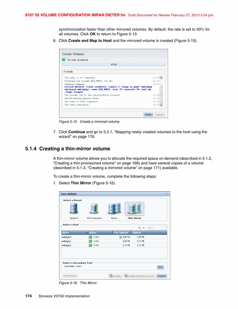
synchronization faster than other mirrored volumes. By default, the rate is set to 50% for all volumes. Click OK to return to Figure 5-13.
6. Click Create and Map to Host and the mirrored volume is created (Figure 5-15).
Figure 5-15 Create a mirrored volume
7. Click Continue and go to 5.2.1, “Mapping newly created volumes to the host using the wizard” on page 176.
5.1.4 Creating a thin-mirror volume
A thin-mirror volume allows you to allocate the required space on demand (described in 5.1.2, “Creating a thin-provisioned volume” on page 168) and have several copies of a volume (described in 5.1.3, “Creating a mirrored volume” on page 171) available.
To create a thin-mirror volume, complete the following steps:
1. Select Thin Mirror (Figure 5-16).
Figure 5-16 Thin Mirror

Chapter 5. Basic volume configuration 175
Draft Document for Review February 27, 2013 3:34 pm 8107 05 VOLUME CONFIGURATION IMRAN DIETER.fm
2. Select the primary pool by clicking it and the view changes to the secondary pool (Figure 5-17).
Figure 5-17 Select pools
3. Select the pool for the secondary copy and enter a name and a size for the new volume (Figure 5-18).
Figure 5-18 Enter a volume name and size
4. The summary shows you the capacity information and the allocated space. You can click Advanced and customize the thin-provision settings (Figure 5-9 on page 170) or the mirror synchronization rate (Figure 5-14 on page 173). If you have opened the advanced settings, click OK to return to Figure 5-18.
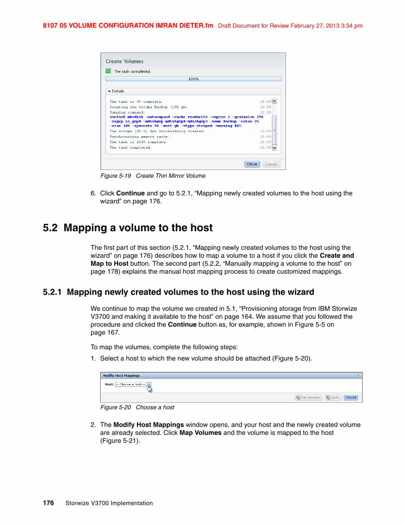
5. Click Create and Map to Host and the mirrored volume is created (Figure 5-19).
8107 05 VOLUME CONFIGURATION IMRAN DIETER.fm Draft Document for Review February 27, 2013 3:34 pm
176 Storwize V3700 Implementation
Figure 5-19 Create Thin Mirror Volume
6. Click Continue and go to 5.2.1, “Mapping newly created volumes to the host using the wizard” on page 176.
5.2 Mapping a volume to the host
The first part of this section (5.2.1, “Mapping newly created volumes to the host using the wizard” on page 176) describes how to map a volume to a host if you click the Create and Map to Host button. The second part (5.2.2, “Manually mapping a volume to the host” on page 178) explains the manual host mapping process to create customized mappings.
5.2.1 Mapping newly created volumes to the host using the wizard
We continue to map the volume we created in 5.1, “Provisioning storage from IBM Storwize V3700 and making it available to the host” on page 164. We assume that you followed the procedure and clicked the Continue button as, for example, shown in Figure 5-5 on page 167.
To map the volumes, complete the following steps:
1. Select a host to which the new volume should be attached (Figure 5-20).
Figure 5-20 Choose a host
2. The Modify Host Mappings window opens, and your host and the newly created volume are already selected. Click Map Volumes and the volume is mapped to the host (Figure 5-21).

Chapter 5. Basic volume configuration 177
Draft Document for Review February 27, 2013 3:34 pm 8107 05 VOLUME CONFIGURATION IMRAN DIETER.fm
Figure 5-21 Modify host mappings
3. After the task completes, click Close (Figure 5-22), and the wizard returns to the All Volumes window.
Figure 5-22 Modify Mappings complete
The newly created volume is displayed. We see that it is already mapped to a host (Figure 5-23).

8107 05 VOLUME CONFIGURATION IMRAN DIETER.fm Draft Document for Review February 27, 2013 3:34 pm
178 Storwize V3700 Implementation
Figure 5-23 New Volume mapped to host
The host is now able to access the volumes and store data on it. Go to 5.3, “Discovering the volumes from the host and specifying multipath settings” on page 180 to discover the volumes on the host and make some additional host settings if required.
You can also create multiple volumes in preparation for discovering them later. Mappings can be customized as well. Advanced host configuration is described in 8.1.1, “Modifying Mappings menu” on page 306.
5.2.2 Manually mapping a volume to the host
We assume that you followed the procedure in 5.1, “Provisioning storage from IBM Storwize V3700 and making it available to the host” on page 164 and clicked Create button as, for example, shown in Figure 5-5 on page 167.
To manually map a volume to the host, complete the following steps:
1. Open the All Hosts window (Figure 5-24 on page 178).
Figure 5-24 Hosts window

Chapter 5. Basic volume configuration 179
Draft Document for Review February 27, 2013 3:34 pm 8107 05 VOLUME CONFIGURATION IMRAN DIETER.fm
2. Right-Click the host to which a volume is to be mapped and select Modify Mappings (Figure 5-25 on page 179).
Figure 5-25 All hosts window
3. The Modify Host Mappings window opens. Select the volume that you want to map from the Unmapped Volumes pane on the left (Figure 5-26).
Figure 5-26 Modify host mappings window
4. Click on the Right-Pointing arrow button, the volume will then be moved to Volumes Mapped to the Host pane on the right (Figure 5-27 on page 180). Repeat this step for all the volumes you want to map and then click Map Volumes.

8107 05 VOLUME CONFIGURATION IMRAN DIETER.fm Draft Document for Review February 27, 2013 3:34 pm
180 Storwize V3700 Implementation
Figure 5-27 Modify host mappings window
5. After the task completes, click Close (Figure 5-28), and the wizard returns to the All Hosts window.
Figure 5-28 Modify mapping complete
The volumes are now mapped and the host is able to access the volumes and store data on them. Go to 5.3, “Discovering the volumes from the host and specifying multipath settings” to discover the volumes on the host and make some additional host settings if required.
5.3 Discovering the volumes from the host and specifying multipath settings
This section shows how to discover the volumes created and mapped in 5.1, “Provisioning storage from IBM Storwize V3700 and making it available to the host” on page 164 and 5.2, “Mapping a volume to the host” on page 176, and set additional multipath settings, if required.

Chapter 5. Basic volume configuration 181
Draft Document for Review February 27, 2013 3:34 pm 8107 05 VOLUME CONFIGURATION IMRAN DIETER.fm
We assume that you have completed all steps described previously in the book, so that the hosts and the IBM Storwize V3700 are prepared:
� Prepare your operating systems for attachment (Chapter 4, “Host configuration” on page 135).
� Create hosts using the GUI (4.3, “Creating hosts using the GUI” on page 150).
� Perform basic volume configuration and host mapping (5.1, “Provisioning storage from IBM Storwize V3700 and making it available to the host” on page 164 and 5.2, “Mapping a volume to the host” on page 176).
This section shows how to discover Fibre Channel and iSCSI volumes from Windows 2008 and VMware ESX 5.x hosts.
In the IBM Storwize V3700 GUI, click Hosts (Figure 5-29).
Figure 5-29 Open all hosts
The view that opens gives you an overview of the currently configured and mapped hosts, in our example we only have one host currently configured (Figure 5-30).
Figure 5-30 All Hosts view

8107 05 VOLUME CONFIGURATION IMRAN DIETER.fm Draft Document for Review February 27, 2013 3:34 pm
182 Storwize V3700 Implementation
5.3.1 Windows 2008 Fibre Channel volume attachment
To perform Fibre Channel volume attachment in Windows 2008, complete the following steps:
1. Right-click your Windows 2008 Fibre Channel host in the All Hosts view (Figure 5-31) and select Properties.
Figure 5-31 Host properties
Navigate to the Mapped Volumes tab (Figure 5-32).
Figure 5-32 Mapped volumes to a host
The host details show you which volumes are currently mapped to the host, and you also see the volume UID and the SCSI ID. In our example, one volume with SCSI ID 0 is mapped to the host.
2. Log on to your Microsoft host and click Start All Programs Subsystem Device Driver DSM Subsystem Device Driver DSM. A command-line interface opens. Enter datapath query device and press Enter to see if there are IBM Storwize V3700 disks connected to this host (Example 5-1).

Chapter 5. Basic volume configuration 183
Draft Document for Review February 27, 2013 3:34 pm 8107 05 VOLUME CONFIGURATION IMRAN DIETER.fm
Example 5-1 datapath query device
C:\Program Files\IBM\SDDDSM>datapath query device
Total Devices : 1
DEV#: 0 DEVICE NAME: Disk1 Part0 TYPE: 2145 POLICY: OPTIMIZEDSERIAL: 60050760009A01D37800000000000000============================================================================Path# Adapter/Hard Disk State Mode Select Errors 0 Scsi Port3 Bus0/Disk1 Part0 OPEN NORMAL 33 0 1 Scsi Port4 Bus0/Disk1 Part0 OPEN NORMAL 0 0
C:\Program Files\IBM\SDDDSM>
3. The output provides information about the connected volumes. In our example, there is one disk connected, Disk 1 for the Windows host, and two paths to the disk are available (State = Open). Open the Windows Disk Management window (Figure 5-33) by clicking Start Run, type diskmgmt.msc, and click OK.
Figure 5-33 Windows Disk Management
4. Right-click the disk in the left pane and select Online if the disk is not online already (Figure 5-34).
Windows device discovery: Usually, Windows discovers new devices, such as disks, by itself. If you have completed all the steps and do not see any disks, click Actions Rescan Disk in Disk Management to discover the new volumes.

8107 05 VOLUME CONFIGURATION IMRAN DIETER.fm Draft Document for Review February 27, 2013 3:34 pm
184 Storwize V3700 Implementation
Figure 5-34 Place a disk online
5. Right-click the disk again, click Initialize Disk (Figure 5-35).
Figure 5-35 Initialize Disk menu
6. Select an initialization option and click OK, in our example we selected MBR (Figure 5-36).

Chapter 5. Basic volume configuration 185
Draft Document for Review February 27, 2013 3:34 pm 8107 05 VOLUME CONFIGURATION IMRAN DIETER.fm
Figure 5-36 Initialize Disk
7. Right-click the right pane and click New Simple Volume (Figure 5-37).
Figure 5-37 New Simple Volume
8. Follow the wizard and the volume is ready to use from your Windows host (Figure 5-38). In our example, we have mapped a 200 GB disk, which is generic on the IBM Storwize V3700, to a Windows 2008 host using Fibre Channel.

8107 05 VOLUME CONFIGURATION IMRAN DIETER.fm Draft Document for Review February 27, 2013 3:34 pm
186 Storwize V3700 Implementation
Figure 5-38 Volume is ready to use
The basic setup is now complete, the IBM Storwize V3700 is configured, and the host is prepared to access the volumes over several paths and is able to store data on the storage subsystem.
5.3.2 Windows 2008 iSCSI volume attachment
To perform iSCSI volume attachment in Windows 2008, complete the following steps:
1. Right-click your Windows 2008 iSCSI host in the All Hosts view (Figure 5-39), click Properties, and navigate to the Mapped Volumes tab (Figure 5-40).
Figure 5-39 All Hosts view

Chapter 5. Basic volume configuration 187
Draft Document for Review February 27, 2013 3:34 pm 8107 05 VOLUME CONFIGURATION IMRAN DIETER.fm
Figure 5-40 Mapped volumes to an iSCSI host
The host details show you which volumes are currently mapped to the host, and you also see the volume UID and the SCSI ID. In our example, one volume with SCSI ID 1 is mapped to the host.
2. Log on to your Windows 2008 host and click Start Administrative Tools iSCSI Initiator to open the iSCSI Configuration tab (Figure 5-41).

8107 05 VOLUME CONFIGURATION IMRAN DIETER.fm Draft Document for Review February 27, 2013 3:34 pm
188 Storwize V3700 Implementation
Figure 5-41 Windows iSCSI Configuration tab
3. Enter the IP address of one of the IBM Storwize V3700 iSCSI ports and click Quick Connect (Figure 5-42).
Figure 5-42 iSCSI Quick Connect
The IBM Storwize V3700 initiator is discovered and connected (Figure 5-43).
iSCSI IP addresses: The iSCSI IP addresses are different for the cluster and canister IP addresses, and they have been configured in 4.3.2, “Creating iSCSI hosts” on page 155.

Chapter 5. Basic volume configuration 189
Draft Document for Review February 27, 2013 3:34 pm 8107 05 VOLUME CONFIGURATION IMRAN DIETER.fm
Figure 5-43 iSCSI Initiator target is connected
Now you have completed the steps to connect the storage disk to your iSCSI host, but you are only using a single path at the moment. To enable multipathing for iSCSI targets, more actions are required. Complete the following steps:
1. Click Start Run and type cmd to open a command prompt. Enter ServerManagerCMD.exe -install Multipath-IO and press Enter (Example 5-2).
Example 5-2 Installing MPIO
C:\Users\Administrator>ServerManagerCmd.exe -Install Multipath-IO
Start Installation...[Installation] Succeeded: [Multipath I/O] Multipath I/O.<100/100>
Success: Installation succeeded.
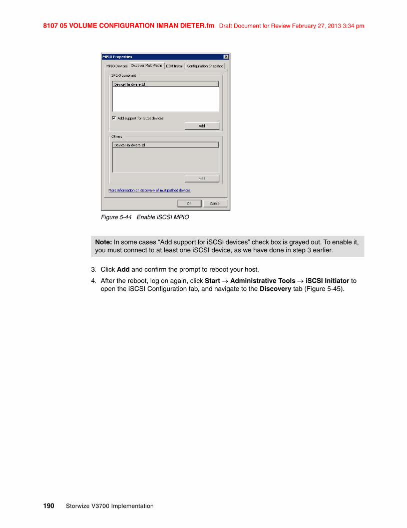
2. Click Start Administrative Tools MPIO, click the Discover Multi-Paths tab, and select the Add support for iSCSI devices check box (Figure 5-44).
8107 05 VOLUME CONFIGURATION IMRAN DIETER.fm Draft Document for Review February 27, 2013 3:34 pm
190 Storwize V3700 Implementation
Figure 5-44 Enable iSCSI MPIO
3. Click Add and confirm the prompt to reboot your host.
4. After the reboot, log on again, click Start Administrative Tools iSCSI Initiator to open the iSCSI Configuration tab, and navigate to the Discovery tab (Figure 5-45).
Note: In some cases “Add support for iSCSI devices” check box is grayed out. To enable it, you must connect to at least one iSCSI device, as we have done in step 3 earlier.

Chapter 5. Basic volume configuration 191
Draft Document for Review February 27, 2013 3:34 pm 8107 05 VOLUME CONFIGURATION IMRAN DIETER.fm
Figure 5-45 iSCSI Properties Discovery tab
5. Click Discover Portal..., enter the IP address of another IBM Storwize V3700 iSCSI port (Figure 5-46), and click OK.
Figure 5-46 Discover Target Portal window
6. Return to the Targets tab (Figure 5-47) and you find the new connection there is listed as Inactive.

8107 05 VOLUME CONFIGURATION IMRAN DIETER.fm Draft Document for Review February 27, 2013 3:34 pm
192 Storwize V3700 Implementation
Figure 5-47 Inactive target ports
7. Highlight the inactive port and click Connect. The Connect to Target window opens (Figure 5-48).
Figure 5-48 Connect to a target
8. Select the Enable Multipath check box and click OK. The second port now appears as Connected (Figure 5-49).

Chapter 5. Basic volume configuration 193
Draft Document for Review February 27, 2013 3:34 pm 8107 05 VOLUME CONFIGURATION IMRAN DIETER.fm
Figure 5-49 Second target port connected
Repeat this step for each IBM Storwize V3700 port you want to use for iSCSI traffic. It is possible to have up to four port paths to the system.
9. Open the Windows Disk Management window (Figure 5-50) by clicking Start Run, typing diskmgmt.msc, and clicking OK.

8107 05 VOLUME CONFIGURATION IMRAN DIETER.fm Draft Document for Review February 27, 2013 3:34 pm
194 Storwize V3700 Implementation
Figure 5-50 Windows Disk Management
10.Set the disk online, initialize it, create a file system on it, and then it is ready to use. The detailed steps of this process are the same as described in 5.3.1, “Windows 2008 Fibre Channel volume attachment” on page 182.
Now the storage disk is ready for use (Figure 5-51). In our example, we have mapped a 100 GB disk, which is generic on the IBM Storwize V3700, to a Windows 2008 host using iSCSI.
Figure 5-51 Windows Disk Management: Disk is ready to use

Chapter 5. Basic volume configuration 195
Draft Document for Review February 27, 2013 3:34 pm 8107 05 VOLUME CONFIGURATION IMRAN DIETER.fm
5.3.3 VMware ESX Fibre Channel attachment
To perform VMware ESX Fibre Channel attachment, complete the following steps:
1. Right-click your VMware ESX Fibre Channel host in the All Hosts view (Figure 5-52) and select Properties
Figure 5-52 Example ESX FC host
Navigate to the Mapped Volumes tab (Figure 5-53).
Figure 5-53 Mapped volumes to ESX FC host
2. In the Host Details window, you see that there is one volume connected to the ESX FC host using SCSI ID 0. The UID of the volume is also displayed.
Connect to your VMware ESX Server using the vSphere client, navigate to the Configuration tab, and select Storage Adapters (Figure 5-54).

8107 05 VOLUME CONFIGURATION IMRAN DIETER.fm Draft Document for Review February 27, 2013 3:34 pm
196 Storwize V3700 Implementation
Figure 5-54 vSphere Client: Storage adapters
3. Click Rescan All... and click OK (Figure 5-55) to scan for new storage devices.
Figure 5-55 Rescan
4. Select Storage and click Add Storage (Figure 5-56).

Chapter 5. Basic volume configuration 197
Draft Document for Review February 27, 2013 3:34 pm 8107 05 VOLUME CONFIGURATION IMRAN DIETER.fm
Figure 5-56 vSphere Client: Storage
5. The Add Storage wizard opens. Click Select Disk/LUN and click Next. The IBM Storwize V3700 disk appears (Figure 5-57). Highlight it and click Next.
Figure 5-57 Select Disk/LUN menu

8107 05 VOLUME CONFIGURATION IMRAN DIETER.fm Draft Document for Review February 27, 2013 3:34 pm
198 Storwize V3700 Implementation
6. Follow the wizard to complete the attachment of the disk. After you click Finish, the wizard closes and you return to the storage view. In Figure 5-58, you see that the new volume has been added to the configuration.
Figure 5-58 Add Storage task complete
7. Highlight the new data store and click Properties to see the details of it (Figure 5-59).
Figure 5-59 Data store properties
8. Click Manage Paths to customize the multipath settings. Select Round Robin (Figure 5-60) and click Change.

Chapter 5. Basic volume configuration 199
Draft Document for Review February 27, 2013 3:34 pm 8107 05 VOLUME CONFIGURATION IMRAN DIETER.fm
Figure 5-60 Select a data store multipath setting
The storage disk is available and ready to use for your VMware ESX server using Fibre Channel attachment.
5.3.4 VMware ESX iSCSI attachment
To perform a VMware ESX iSCSI attachment, complete the following steps:
1. Right-click your VMware ESX iSCSI host in the All Hosts view (Figure 5-61) and select Properties.
Figure 5-61 Select iSCSI ESX host properties
Navigate to the Mapped Volumes tab (Figure 5-62).

8107 05 VOLUME CONFIGURATION IMRAN DIETER.fm Draft Document for Review February 27, 2013 3:34 pm
200 Storwize V3700 Implementation
Figure 5-62 iSCSI ESX host properties
2. In the Host Details window, you see that there is one volume connected to the ESX iSCSI host using SCSI ID 1. The UID of the volume is also displayed.
Connect to your VMware ESX Server using the vSphere Client, navigate to the Configuration tab, and select Storage Adapters (Figure 5-63).
Figure 5-63 vSphere Client: Storage Adapters
3. Highlight the iSCSI Software Adapter and click Properties. The iSCSI initiator properties window opens. Select the Dynamic Discovery tab (Figure 5-64) and click Add.

Chapter 5. Basic volume configuration 201
Draft Document for Review February 27, 2013 3:34 pm 8107 05 VOLUME CONFIGURATION IMRAN DIETER.fm
Figure 5-64 iSCSI Initiator properties
4. To add a target, enter the target IP address (Figure 5-65). The target IP address is the IP address of a node in the I/O group from which you are mapping the iSCSI volume. Leave the IP port number at the default value of 3260, and click OK. The connection between the initiator and target is established.
Figure 5-65 Enter a target IP address
Repeat this step for each IBM Storwize V3700 iSCSI port you want to use for iSCSI connections.
5. After you have added all the ports required, close the iSCSI Initiator properties by clicking Close (Figure 5-64).
iSCSI IP addresses: The iSCSI IP addresses are different for the cluster and canister IP addresses; they have been configured in 4.3.2, “Creating iSCSI hosts” on page 155.

8107 05 VOLUME CONFIGURATION IMRAN DIETER.fm Draft Document for Review February 27, 2013 3:34 pm
202 Storwize V3700 Implementation
You are prompted to rescan for new storage devices. Confirm the scan by clicking Yes (Figure 5-66).
Figure 5-66 Confirm the rescan
6. Go to the storage view shown in Figure 5-67 and click Add Storage.
Figure 5-67 Add Storage menu
7. The Add Storage wizard opens (Figure 5-68). Select Disk/LUN and click Next.

Chapter 5. Basic volume configuration 203
Draft Document for Review February 27, 2013 3:34 pm 8107 05 VOLUME CONFIGURATION IMRAN DIETER.fm
Figure 5-68 Select Disk/LUN menu
8. The new iSCSI LUN displays. Highlight it and click Next (Figure 5-69).
Figure 5-69 Select iSCSI LUN menu

8107 05 VOLUME CONFIGURATION IMRAN DIETER.fm Draft Document for Review February 27, 2013 3:34 pm
204 Storwize V3700 Implementation
9. Select a File System version option. In our example we selected VMFS-5 (Figure 5-70).
Figure 5-70 Select file system
10.Review the disk layout and click Next (Figure 5-71).
Figure 5-71 Current Disk Layout

Chapter 5. Basic volume configuration 205
Draft Document for Review February 27, 2013 3:34 pm 8107 05 VOLUME CONFIGURATION IMRAN DIETER.fm
11.Enter a name for the data store and click Next (Figure 5-72).
Figure 5-72 Enter a data store name
12.Select the Maximum available space and click Next (Figure 5-73).
Figure 5-73 Capacity

8107 05 VOLUME CONFIGURATION IMRAN DIETER.fm Draft Document for Review February 27, 2013 3:34 pm
206 Storwize V3700 Implementation
13.Review your selections and click Finish (Figure 5-74).
Figure 5-74 Finish the wizard
The new iSCSI LUN is now in the process of being added; this task can take a few minutes. After the tasks complete, the new data store appears in the storage view (Figure 5-75).
Figure 5-75 New data store available
Chapter 5. Basic volume configuration 207
Draft Document for Review February 27, 2013 3:34 pm 8107 05 VOLUME CONFIGURATION IMRAN DIETER.fm
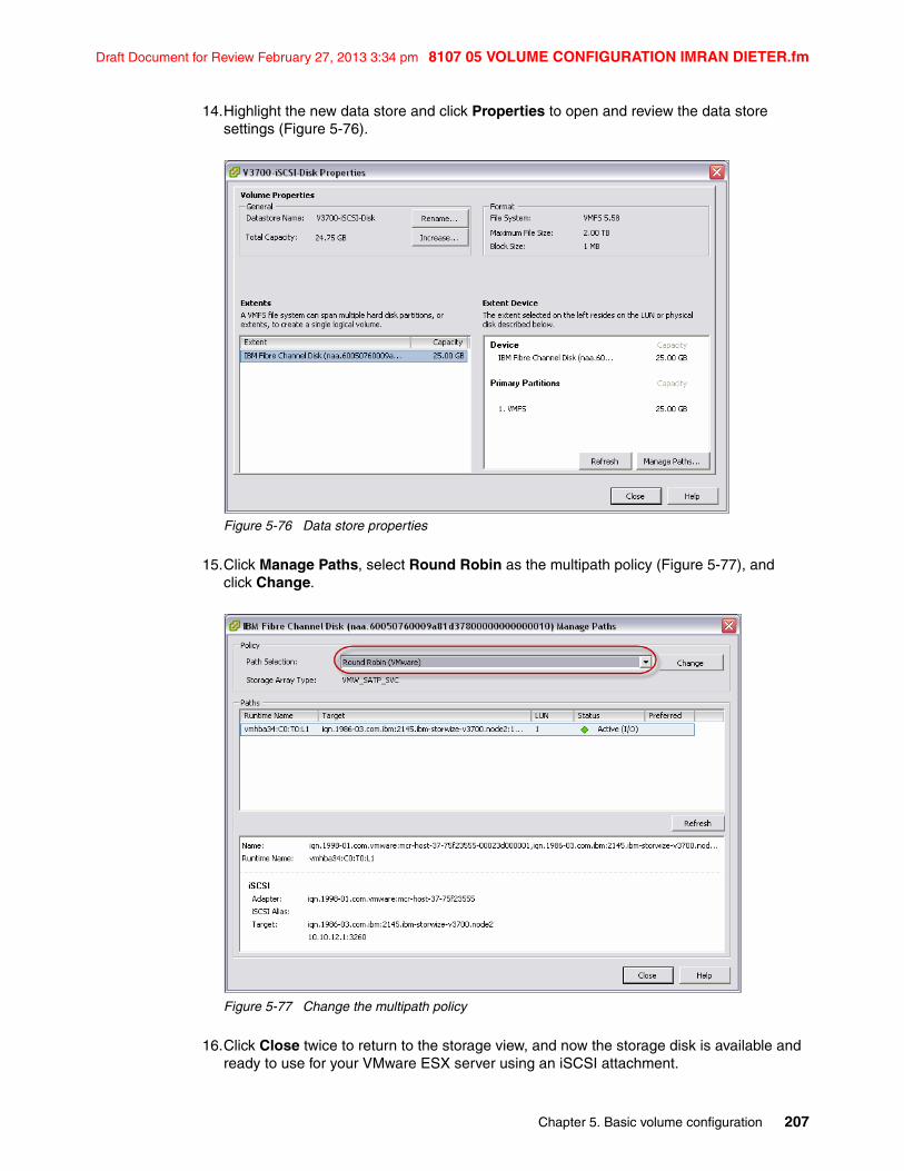
14.Highlight the new data store and click Properties to open and review the data store settings (Figure 5-76).
Figure 5-76 Data store properties
15.Click Manage Paths, select Round Robin as the multipath policy (Figure 5-77), and click Change.
Figure 5-77 Change the multipath policy
16.Click Close twice to return to the storage view, and now the storage disk is available and ready to use for your VMware ESX server using an iSCSI attachment.

8107 05 VOLUME CONFIGURATION IMRAN DIETER.fm Draft Document for Review February 27, 2013 3:34 pm
208 Storwize V3700 Implementation

© Copyright IBM Corp. 2012. All rights reserved. 209
Draft Document for Review February 27, 2013 3:34 pm 8107 06 Migration Wizard JUSTIN IMRAN.fm
Chapter 6. Storage migration wizard
This chapter describes the easy to follow storage migration wizard. The storage migration wizard is used to migrate data from older external storage systems to the internal capacity of the Storwize V3700. Migrating data from older storage systems to the Storwize V3700 storage system provides benefit from additional functionality, such as the easy to use GUI, internal virtualization, thin provisioning, and FlashCopy.
6
8107 06 Migration Wizard JUSTIN IMRAN.fm Draft Document for Review February 27, 2013 3:34 pm
210 Storwize V3700 Implementation
6.1 Interoperability and compatibility
Interoperability is an important consideration when setting up a new storage system in an environment that contains existing storage infrastructure. In this section, we show how to check the storage environment, the older storage system, and the IBM Storwize V3700 are ready for the data migration process.
To ensure system interoperability and compatibility between all elements connected to the SAN fabric, check the proposed configuration with the IBM System Storage Interoperation Center (SSIC). SSIC can confirm the solution is supported and also provides recommended hardware and software levels.
If a desired configuration is not listed for support in the SSIC then contact your IBM marketing representative to request a Request for Price Quotation (RPQ) for your specific configuration.
IBM System Storage Interoperation Center (SSIC) http://www-03.ibm.com/systems/support/storage/ssic/interoperability.wss
6.2 .The storage migration wizard
The Storwize V3700 storage migration wizard, simplifies migration. The wizard has been designed to be one-way with easy to follow panels to guide users through the entire process. The process involves external virtualization of the older storage system, then an online migration is performed. Once data migration is complete the older storage system is removed from Storwize V3700 control and can be retired.
6.2.1 External virtualization capability
To migrate data from an older storage system to the internal capacity of the Storwize V3700, it is necessary to temporarily take advantage of the built-in external virtualization capability. This capability will place external fibre channel connected Logical Units (LU) under the control of the Storwize V3700. Control of the external LUs is established by using and following the storage migration wizard. The built-in external virtualization capability of the Storwize V3700 can only be used for one-way data migration purposes, any other use of this feature is not supported. If a permanent external virtualization solution is required then the Storwize V7000, Storwize V7000 Unified or SAN Volume Controller should be considered.
6.2.2 Overview of the storage migration wizard
An overview of the storage migration wizard process:
� The older storage systems divide storage into many Small Computer System Interface (SCSI) logical units (LUs) that are presented on the fibre channel SAN to hosts.
� I/O to the LUs is stopped and changes are made to the storage system LUs mappings and to the SAN fabric zoning so that the original LUs are presented directly to the Storwize V3700. The Storwize V3700 discovers the external LUs as unmanaged MDisks.
Note: The Storwize V3700 node canisters require an appropriate optional Host Interface Card (HIC) to communicate with storage systems attached to the same Fibre Channel SAN.

Chapter 6. Storage migration wizard 211
Draft Document for Review February 27, 2013 3:34 pm 8107 06 Migration Wizard JUSTIN IMRAN.fm
� The unmanaged MDisks are then imported to the Storwize V3700 as image mode MDisks and placed into storage pool named MigrationPool_8192. This storage pool is now a logical container for the SAN attached LUs.
� Image mode volumes are created from MigrationPool_8192. Each volume has a one to one mapping with an image mode MDisk. From a data perspective, the image mode volume represents the SAN attached LUs exactly as it was before the import operation. The image mode volume will reside on the same physical drives of the older storage system with the data remaining unchanged. The Storwize V3700 is simply presenting active images of the SAN attached LUs.
� The hosts will have the older storage system multipath device driver removed and then be configured for Storwize V3700 attachment. Further zoning changes are made for host-to-V3700 SAN connections. The Storwize V3700 hosts are defined with WWPNs and the volumes are mapped. Once the volumes are mapped the hosts will discover the Storwize V3700 volumes through a host rescan devices, or reboot operation.
� Storwize V3700 volume mirror operations are then initiated. The image mode volumes are mirrored to generic volumes. The generic volumes are from user nominated internal storage pools. The mirrors are online migration tasks, which means a defined host can access and use the volumes during the mirror synchronization process.
� Once the mirror operations are complete, the migrations are then finalized by user. The finalization process is seamless, it removes the volume mirror relationships and the image mode volumes. The older storage system LUs have now been migrated and the Storwize V3700 LUs control to that old LUs can then be removed.
6.2.3 Storage migration wizard tasks
The storage migration wizard is designed for the easy and non-disruptive, migration of data from an older storage system to the internal capacity of the Storwize V3700.
This section describes the following storage migration wizard tasks.
� Avoiding data loss� Accessing the storage migration wizard� Wizard Step 1 Before you begin� Wizard Step 2 Prepare environment for migration� Wizard Step 3 Map storage� Wizard Step 4 Migrating MDisks� Wizard Step 5 Configure hosts� Wizard Step 6 Map volumes to hosts� Wizard Step 7 Select storage pool� Wizard Step 8 Finish the storage migration wizard� Finalize migrated volumes
Avoiding data lossThe risk of losing data when correctly using the storage migration wizard is very low. However, it is prudent to avoid potential data loss by creating a backup of all the data stored on the hosts, the older storage systems and the Storwize V3700 before using the wizard.
Accessing the storage migration wizardSelect System Migration in the Pools menu to reveal the System Migration panel. The System Migration panel provides access to the storage migration wizard and displays migration progress information. Figure 6-1 shows the pools menu.

8107 06 Migration Wizard JUSTIN IMRAN.fm Draft Document for Review February 27, 2013 3:34 pm
212 Storwize V3700 Implementation
Figure 6-1 Pools menu
Click Start New Migration and the storage migration wizard will be revealed. Figure 6-2 shows the system migration panel.
Figure 6-2 System migration panel
Wizard step 1 before you beginFollow the storage migration wizard step 1 of 8 panel, it describes the restrictions and prerequisites. Read the restrictions and prerequisites, and then check the boxes adjacent to each item that will apply to the planned migration. Refer to Figure 6-3 on page 213.
Restrictions:� I am not using the storage migration wizard to migrate cluster hosts, including cluster of
VMware hosts and VIOS.
� I am not using the storage migration wizard to migrate SAN Boot images.

Chapter 6. Storage migration wizard 213
Draft Document for Review February 27, 2013 3:34 pm 8107 06 Migration Wizard JUSTIN IMRAN.fm
If the restrictions boxes cannot be checked, the migration must be performed outside of this wizard for additional steps are required. Further information about this topic can be found in the IBM Storwize V3700 Information Center.
IBM Storwize V3700 Version 6.4.1 Information Center http://pic.dhe.ibm.com/infocenter/storwize/v3700_ic/index.jsp
The VMware ESX Storage vMotion feature might be an alternative for migrating VMware clusters. For more information about this topic, see the following address:
http://www.vmware.com/products/vmotion/overview.html
Prerequisites:� Make sure that the Storwize V3700, older storage system, and hosts, fibre channel ports
have been physically connected to the SAN fabrics.
� If there are VMware ESX hosts involved in the data migration, make sure the VMware ESX hosts are set to allow volume copies to be recognized. For further information see the VMware ESX product documentation. http://www.vmware.com/support/pubs/vsphere-esxi-vcenter-server-pubs.html?
If all boxes can be checked, click the Next to continue. In all other cases Next will not be selectable and the data will need to be migrated without use of this wizard. Figure 6-3 shows step 1 of the storage migration wizard with all restrictions satisfied and prerequisites met.
Figure 6-3 Step 1 of the storage migration wizard, with all boxes checked
Wizard step 2 prepare environment for migrationFollow the storage migration wizard step 2 of 8 panel carefully. When all of the required actions have been completed, then click Next to continue. Figure 6-4 on page 214 shows the prepare environment for migration panel.

8107 06 Migration Wizard JUSTIN IMRAN.fm Draft Document for Review February 27, 2013 3:34 pm
214 Storwize V3700 Implementation
Figure 6-4 Prepare environment for migration panel
Wizard step 3 map storageFollow the storage migration wizard step 3 of 8 panel and click Next to continue. Record all the details carefully for the information can be used in later panels. Table 6-1 shows an example table for capturing the information relating to older storage system LUs.
Table 6-1 Example table for capturing external LU information
Table 6-2 shows an example table for capturing host information.
LU Name Controller Array SCSI ID HOST NAME Capacity
MCRPRDW2K801 DS3400_01 Array_01 0 MCRPRDW2K8 50 GB
MCRPRDW2K802 DS3400_01 Array_01 1 MCRPRDW2K8 200 GB
MCRPRDLNX01 DS3400_01 Array_02 0 MCRPRDLNX 100 GB
MCRPRDLNX02 DS3400_01 Array_02 1 MCRPRDLNX 300 GB
SCSI ID:
Record the SCSI ID of the LUs to which the host is originally mapped. Some operating systems do not support changing the SCSI ID during the migration.

Chapter 6. Storage migration wizard 215
Draft Document for Review February 27, 2013 3:34 pm 8107 06 Migration Wizard JUSTIN IMRAN.fm
Table 6-2 Example table for capturing host information
Figure 6-5 on page 215 shows the map storage panel.
Figure 6-5 Map storage panel
Host Name/LU Names
Adapter / Slot / Port WWPN HBA F/W
HBA Device Driver
OperatingSystem
V3700 MultipathS/W
MCRPRDW2K8 QLE2562 / 2 / 1 21000024FF2D0BE8 2.10 9.1.9.25 W2K8 R2 SP1
SDDDSM2.4.3.1-2
MCRPRDW2K8 QLE2562 / 2 / 2 21000024FF2D0BE9 2.10 9.1.9.25 W2K8 R2 SP1
SSDDSM 2.4.3.1-2
MCRPRDLNX LP10000 / 0 / 1 10000000C1234A56 2.72a2 8.2.0.63.3p RHEL5 Device Mapper
MCRPRDLNX LP10000 / 1 / 1 10000000C6789A01 2.72a2 8.2.0.63.3p RHEL5 DeviceMapper

8107 06 Migration Wizard JUSTIN IMRAN.fm Draft Document for Review February 27, 2013 3:34 pm
216 Storwize V3700 Implementation
The Storwize V3700 will then run the discover devices task. Once the task has completed successfully, click Close to continue. Figure 6-6 on page 216 shows the results of the discover devices task.
Figure 6-6 Discover devices task
Wizard step 4 migrating MDisksFollow the storage migration wizard step 4 of 8 panel and select the MDisks that will be migrated and then click Next to continue. Figure 6-7 shows the migrating MDisks panel.
MDisk selection:
Only select the MDisks that are applicable to the current migration plan. Once the migration is in progress after step 8, another migration plan can be initiated to migrate any remaining MDisks.

Chapter 6. Storage migration wizard 217
Draft Document for Review February 27, 2013 3:34 pm 8107 06 Migration Wizard JUSTIN IMRAN.fm
Figure 6-7 Migrating MDisks panel
The Storwize V3700 will then run the import MDisks task. Once the task has completed successfully, click Close to continue. Figure 6-8 shows the result of the import MDisks task.
Figure 6-8 Import MDisks task

8107 06 Migration Wizard JUSTIN IMRAN.fm Draft Document for Review February 27, 2013 3:34 pm
218 Storwize V3700 Implementation
Wizard step 5 configure hostsFollow the storage migration wizard step 5 of 8 panel, select or configure new hosts as required and then click Next to continue. Figure 6-9 shows the configure hosts panel.
Figure 6-9 Configure hosts panel
Wizard step 6 map volumes to hostsFollow the storage migration wizard step 6 of 8 panel, select the newly migrated volume and click Map to Host. Figure 6-10 shows the map volumes to hosts panel.
Note: It is not mandatory to select the hosts at this time, the actual selection of the hosts occurs in the next step entitled ‘Map Volumes to Hosts’. However take this opportunity to cross-check the hosts that have data to be migrated by highlighting them in the list, before clicking Next.

Chapter 6. Storage migration wizard 219
Draft Document for Review February 27, 2013 3:34 pm 8107 06 Migration Wizard JUSTIN IMRAN.fm
Figure 6-10 Map volumes to hosts panel
The image mode volumes are listed, the names of the image mode volumes have been assigned automatically by the Storwize V3700 storage system. The names can be changed to reflect something more meaningful to the user. Select the volume and use Rename in the Actions drop-down menu.
A Host drop-down menu is then displayed, select the desired host and the modify host mappings panel will be revealed. Figure 6-11 shows the Host drop-down menu.
Figure 6-11 Host drop-down menu
The MDisks previously highlight in step 6 of the storage migration wizard will be shown in yellow highlights on the Modify Host Mappings panel. The yellow highlighting means that the volumes are not yet mapped to the host. Take this opportunity to click Edit SCSI ID and modify as required, it should reflect the same SCSI ID recorded in Step 3. Click Map Volumes. Figure 6-12 shows the modify host mapping panel.
Names: The names must begin with a letter. The name can be a maximum of 63 characters. Valid characters are uppercase letters (A-Z), lowercase letters (a-z), digits (0 - 9), underscore (_), period (.), hyphen (-), and space. The names must not begin or end with a space.

8107 06 Migration Wizard JUSTIN IMRAN.fm Draft Document for Review February 27, 2013 3:34 pm
220 Storwize V3700 Implementation
Figure 6-12 Modify hosts mappings panel
The Storwize V3700 will then run the modify mappings task. Once the task has completed successfully the volume is mapped to the host, click Close to continue. Figure 6-13 shows the modify mappings task.
Figure 6-13 Modify mappings tasks
The Map Volumes to Hosts panel is displayed again. Verify that newly migrated volumes now have “Yes” in the “Host Mappings” column. Then click Next to continue. Figure 6-14 on page 221 shows the map volume to hosts panel with “Yes” in the host mappings column.

Chapter 6. Storage migration wizard 221
Draft Document for Review February 27, 2013 3:34 pm 8107 06 Migration Wizard JUSTIN IMRAN.fm
Figure 6-14 Map volumes to hosts panel displaying “yes” in the host mappings column
Scan for new devices on the hosts to verify the mapping. The disks are now displayed as IBM 2145 Multi-Path disk devices. This disk device type is common for the IBM Storwize disk family, and the IBM SAN Volume Controller.
Wizard step 7 select storage poolFollow the storage migration wizard step 7 of 8 panel, select an internal storage pool and then click Next to continue. The destination storage pool of the data migration will be an internal storage pool of the Storwize V3700. Ensure that there is enough space in the selected storage pool to accommodate the migrated volume. The migration task runs in the background and results in a copy of the data being placed on the MDisks in the selected storage pool. The process uses the volume mirroring function included with the Storwize V3700, and when complete, the volumes have pointers to both the new copy on the internal storage pool selected and on the older storage system.Figure 6-15 shows the select storage pool panel.
Figure 6-15 Select a storage pool panel

8107 06 Migration Wizard JUSTIN IMRAN.fm Draft Document for Review February 27, 2013 3:34 pm
222 Storwize V3700 Implementation
The Storwize V3700 will then run the start migration task. Once the task has completed successfully, click Close to continue. Figure 6-16 on page 222 shows the result of the start migration task.
Figure 6-16 Start migration task
Wizard step 8 finish the storage migration wizardFollow the storage migration wizard step 8 of 8 panel, and click FINISH. Figure 6-17 shows step 8 of 8 of the storage migrate wizard.
Figure 6-17 Step 8 of 8 of the storage migration wizard
The end of the storage migration wizard is not the end of the data migration. The data migration has begun and in progress. A percentage indication of the migration progress is

Chapter 6. Storage migration wizard 223
Draft Document for Review February 27, 2013 3:34 pm 8107 06 Migration Wizard JUSTIN IMRAN.fm
displayed in the System Migration panel. Figure 6-18 on page 223 shows the System Migration panel migration progress percentage indicator.
Figure 6-18 Storage Migration panel with a migration in progress
Finalize migrated volumesWhen the migration completes, select the Migration and right click Finalize. Verify the volume names and the number of migrations and click OK. The image mode volumes are deleted and the associated image mode MDisks from the migration storage pool are removed; the status of those image mode MDisks is then unmanaged. When the finalization completes, the data migration to the IBM Storwize V3700 is done. Remove zoning and retire the older storage system.
6.3 Storage migration wizard example scenario
This section provides an example scenario, this is to provide some additional detail relating to the attachment and verification tasks associated with running the storage migration wizard.
6.3.1 Storage migration wizard example scenario description
The example scenario shows the introduction of a Storwize V3700 to an environment that contains existing storage infrastructure which includes a SAN fabric, and a Windows 2008 host, and an IBM DS3400 storage system.
The Windows 2008 host has existing data residing on the disks of an IBM DS3400 storage system and that data will need to be migrated to the internal storage of the Storwize V3700. The Windows 2008 host has a dual port Qlogic Host Bus Adapter (HBA) type QLE2562. Each of the fibre channel switches are of type IBM 2498-24B. There are two host disks to be migrated which are devices Disk 1 and Disk 2. Figure 6-19 shows the Windows 2008 Disk management panel. The two disks have volumes defined, the volume labels are Migration 1 and Migration 2 and have also been assigned drive letters of G: and H: respectively.
Figure 6-19 Windows 2008 disk management panel
The two disks to be migrated are currently residing on the IBM DS3400 storage system, hence, the disk properties will display the disk device type as an ‘IBM1726-4xx FAStT disk

8107 06 Migration Wizard JUSTIN IMRAN.fm Draft Document for Review February 27, 2013 3:34 pm
224 Storwize V3700 Implementation
device’. To shows this disk attribute, right click on the disk to reveal the menu and then select Properties. Figure 6-20 on page 224 shows the disk’s right click menu.
Figure 6-20 Display properties of disk before migration
Once the disk properties panel has been revealed, the General tab will show the disk device type. Figure 6-21 on page 225shows the Windows 2008 disk properties general tab.

Chapter 6. Storage migration wizard 225
Draft Document for Review February 27, 2013 3:34 pm 8107 06 Migration Wizard JUSTIN IMRAN.fm
Figure 6-21 Window 2008 disk properties - general tab
Perform this task on all disks before the migration and then the same check can be done after the disks are presented from the Storwize V3700. If after the Storwize V3700 mapping and host rescan, the disk device definitions are changed to ‘IBM 2145 Multi-Path disk device’ it will confirm that the disks are under Storwize V3700 control.
Example scenario fibre channel cabling layout To provide additional information about the example migration. Figure 6-22 shows the example scenario fibre channel cabling layout. The Host, IBM DS3400, and Storwize V3700 are cabled into a dual SAN fabric configuration. The connection method shown can provide improved availability through fabric and path redundancy, and improved performance through workload balancing.

8107 06 Migration Wizard JUSTIN IMRAN.fm Draft Document for Review February 27, 2013 3:34 pm
226 Storwize V3700 Implementation
Figure 6-22 Example scenario Fibre Channel cabling layout
6.3.2 Using the storage migration wizard for example scenario
The following section provides an overview of the storage migration tasks to be performed when using the storage migration wizard for the example scenario. Then a more detailed perspective is provided to assist users that require additional information.
Overview of storage migration wizard tasks for example scenario1. Search IBM System Storage Interoperation Center (SSIC) for scenario compatibility.
2. Backup all data associated with the host, DS3400 and Storwize V3700.
3. Start New Migration to reveal the wizard on the Storwize V3700.
4. Follow wizard step 1 before you begin.
5. Follow wizard step 2 prepare environment for migration
a. Stop host operations, or stop all I/O to volumes that you are migrating.
b. Remove zones between the hosts and the storage system from which you are migrating.
– Remove Host-to-DS3400 zones on SAN
c. Update your host device drivers, including your multipath driver and configure them for attachment to this system. Complete the steps in 4.2.1, “Windows 2008 (R2): Preparing for Fibre Channel attachment” on page 137 to connect to Storwize V3700 using Fibre Channel.
– Make sure that the latest OS service pack and test fixes are applied to your Microsoft server.
– Use the latest firmware and driver levels on your host system.– Install HBA or HBAs on the Windows server using the latest BIOS and drivers.– Connect the FC Host Adapter ports to the switches.

Chapter 6. Storage migration wizard 227
Draft Document for Review February 27, 2013 3:34 pm 8107 06 Migration Wizard JUSTIN IMRAN.fm
– Configure the switches (zoning).– Configure the HBA for hosts running Windows.– Set the Windows time-out value.– Install the SDDDSM multipath module.
d. Create a storage system zone between the storage system being migrated and this system, and host zones for the hosts being migrated.
– Locate the World Wide Port Numbers (WWPNs) for Host.– Locate WWPNs for IBM DS3400– Locate WWPNs for Storwize V3700– Define port aliases definitions on SAN.– Add V3700-to-DS3400 zones on SAN.– Add Host-to-V3700 zones on SAN.
e. Create a host or host group in the external storage system with the WWPNs for this system. Attention: If the external storage system does not allow you to restrict volume access to specific hosts, all volumes on the system must be migrated.
– Add Storwize V3700 host group on DS3400
f. Configure the storage system for use with this system.
– Follow the IBM Storwize V3700 Version 6.4.1 Information Center for DS3400 configuration recommendations.
6. Follow wizard step 3 map storage
a. Create a list of all external storage system volumes that are being migrated.
– Create DS3400 LU table
b. Record the hosts that use each volume.
– Create Host table
c. Record the WWPNs associated with each host.
– Add WWPNs to Host table
d. Unmap all volumes being migrated from the hosts in the storage system, and map them to the host or host group you created when preparing your environment. Attention: If the external storage system does not allow you to restrict volume access to specific hosts, all volumes on the system must be migrated.
– Move LUs from Host to Storwize V3700 Host Group on DS3400.
e. Record the storage system LUN used to map each volume to this system.
– Update DS3400 LU table
7. Follow wizard step 4 migrating MDisks
– Select discovered MDisk on Storwize V3700
8. Wizard step 5 configure hosts
– Create Host on Storwize V3700– Select Host on Storwize V3700
9. Wizard step 6 map volumes to hosts
– Map volumes to Host on Storwize V3700– Verify disk device type is now 2145 on Host– SDDDSM datapath query commands on Host
10.Wizard step 7 select storage pool
– Select internal storage pool on Storwize V3700

8107 06 Migration Wizard JUSTIN IMRAN.fm Draft Document for Review February 27, 2013 3:34 pm
228 Storwize V3700 Implementation
11.Wizard step 8 finish the storage migration wizard
12.Finalize migrated volumes
Detailed view of the storage migration wizard for the example scenario1. Search IBM System Storage Interoperation Center (SSIC) for scenario compatibility.2. Backup all data associated with the host, DS3400 and Storwize V3700.3. Start New Migration to reveal the wizard on the Storwize V3700. Figure 6-23 on page 228
shows how to start a new migration.
Figure 6-23 Start new migration
4. Follow the storage migration wizard step 1 entitled ‘Before You Begin’ and check all of the restrictions and prerequisites, then click Next to continue. Figure 6-24 shows all of the items checked in the step 1 of the storage migration wizard.

Chapter 6. Storage migration wizard 229
Draft Document for Review February 27, 2013 3:34 pm 8107 06 Migration Wizard JUSTIN IMRAN.fm
Figure 6-24 Storage migration wizard step 1 of 8
5. Follow the storage migration wizard step 2 entitled ‘Prepare Environment for Migration’. Complete all the steps to before continuing. Figure 6-25 on page 230 shows the storage migration panel step 2.

8107 06 Migration Wizard JUSTIN IMRAN.fm Draft Document for Review February 27, 2013 3:34 pm
230 Storwize V3700 Implementation
Figure 6-25 Storage migration wizard step 2 of 8
a. Stop host operations, or stop all I/O to volumes that you are migrating.b. Remove zones between the hosts and the storage system from which you are
migrating.c. Update your host device drivers, including your multipath driver and configure them for
attachment to this system. Complete the steps in 4.2.1, “Windows 2008 (R2): Preparing for Fibre Channel attachment” on page 137 to prepare a Windows host to connect to Storwize V3700 using Fibre Channel.
– Make sure that the latest OS service pack and test fixes are applied to your Microsoft server.
– Use the latest firmware and driver levels on your host system.– Install HBA or HBAs on the Windows server using the latest BIOS and drivers.– Connect the FC Host Adapter ports to the switches.– Configure the switches (zoning).– Configure the HBA for hosts running Windows.– Set the Windows time-out value.– Install the multipath module.d. Create a storage system zone between the storage system being migrated and this
system, and host zones for the hosts being migrated.

Chapter 6. Storage migration wizard 231
Draft Document for Review February 27, 2013 3:34 pm 8107 06 Migration Wizard JUSTIN IMRAN.fm
To perform this step, locate the World Wide Port Names (WWPNs) of the host, IBM DS3400, and Storwize v3700, then create an alias for each port to simplify the zone creation steps.
Locating the HBA WWPNs on the Windows 2008 hostRefer to the original IBM DS3400 Host definition to locate the World Wide Port Numbers (WWPNs) of the host’s dual port QLE2562 Host Bus Adapter (HBA). To do this open the IBM DS3400 Storage Manager, and click the Modify tab, and then select Edit Host Topology to reveal the host definitions. Figure 6-26 shows the IBM DS3400 Modify tab.
Figure 6-26 IBM DS3400 modify tab: Edit Host Topology
Figure 6-27 shows the IBM DS3400 storage manager host definition and the associated WWPNs.
Figure 6-27 IBM DS3400 host definition
Record the WWPNs for alias, zoning and the Storwize V3700 ‘New Host’ task.
Locating the controller WWPNs on the IBM DS3400The IBM DS3400 Storage Manager can provide the controller WWPNs through the Storage Subsystem Profile. Open the IBM DS3400 Storage Manager, and click the Support and select View Storage Subsystem Profile. Figure 6-28 shows the IBM DS3400 Storage Manager Support tab.
Note: A WWPN is the World Wide Port Name, it is a unique identifier for each Fibre Channel port presented to the SAN fabric.
Note: Alternatively, the Qlogic SAN Surfer application for the Qlogic HBAs, or the SAN fabric switch reports, can be used to locate the host’s WWPNs.
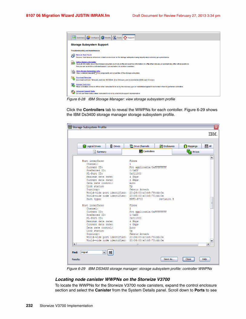
8107 06 Migration Wizard JUSTIN IMRAN.fm Draft Document for Review February 27, 2013 3:34 pm
232 Storwize V3700 Implementation
Figure 6-28 IBM Storage Manager: view storage subsystem profile
Click the Controllers tab to reveal the WWPNs for each contoller. Figure 6-29 shows the IBM Ds3400 storage manager storage subsystem profile.
Figure 6-29 IBM DS3400 storage manager: storage subsystem profile: controller WWPNs
Locating node canister WWPNs on the Storwize V3700To locate the WWPNs for the Storwize V3700 node canisters, expand the control enclosure section and select the Canister from the System Details panel. Scroll down to Ports to see

Chapter 6. Storage migration wizard 233
Draft Document for Review February 27, 2013 3:34 pm 8107 06 Migration Wizard JUSTIN IMRAN.fm
the associated WWPNs. Figure 6-30 shows the Storwize V3700 System Details panel with the WWPNs revealed for IBM-Storwize-V3700 Enclosure 1 Canister 1.
Figure 6-30 Storwize V3700 node canister WWPNs information
Example scenario Storwize V3700 and IBM DS3400 WWPN diagramEach port on the Storwize V3700 and IBM DS3400 has a unique and persistent WWPN. This means if an HA (Host Adapter) in the storage system gets replaced, the new HA will present the same WWPNs as the old HA. This means that if you understand the WWPN of a port, you can match it to the storage system and the fibre channel port. Figure 6-31 on page 234 shows the relationship between the device WWPNs and the fibre channel ports for the Storwize V3700 and the IBM DS3400 used in the example scenario.
Note: The WWPN is made up of eight bytes (2 digits per byte). In Figure 6-30, the third last byte in the listed WWPNs are 10, 0C, 08, 04 respectively, they are the only differing bytes for each WWPN. Also, the last two bytes in the listed example of 04DE will be unique for each node canister. Noticing these types of patterns can help when zoning or trouble shooting SAN issues.

8107 06 Migration Wizard JUSTIN IMRAN.fm Draft Document for Review February 27, 2013 3:34 pm
234 Storwize V3700 Implementation
Figure 6-31 Example scenario Storwize V3700 and IBM DS3400 WWPN location diagram
Zoning - define aliases on the SAN fabricsNow the WWPNs for Storwize V3700, IBM DS3400 and Windows 2008 host have been located. Define the WWPN aliases on the SAN fabrics for the Storwize V3700, create aliases for the DS3400 and Windows 2008 host if they have not already been created. Aliases can simplify the zone creation process. Create an alias name for each interface then add the WWPN.
Aliases can contain the FC Switch Port to which the device is attached, or the attached device’s WWPN. In this example scenario WWPN based zoning is used instead of port based zoning. Either method can be used, however it is best not to intermix the methods and keep the zoning configuration consistent throughout the fabric.
When using WWPN based zoning, be mindful when host HBA cards are replaced, there can be occasions when a new HBA card contains new WWPNs and as a consequence the previously defined aliases will need to be modified to match the new card. This is not the case for IBM Storage Systems for they use persistent WWPNs which means the WWPNs will remain unchanged after a HA card replacement.
Refer to Figure 6-31 for the following alias definitions.
Storwize V3700 ports connected to SAN Fabric A:alias= V3700_Canister_Left_Port1 wwpn= 50:05:07:68:03:04:04:DEalias= V3700_Canister_Left_Port3 wwpn= 50:05:07:68:03:0C:04:DE

Chapter 6. Storage migration wizard 235
Draft Document for Review February 27, 2013 3:34 pm 8107 06 Migration Wizard JUSTIN IMRAN.fm
alias= V3700_Canister_Right_Port1 wwpn= 50:05:07:68:03:04:4D:E0alias= V3700_Canister_Right_Port3 wwpn= 50:05:07:68:03:0C:4D:E0
Storwize V3700 ports connected to SAN Fabric B:alias= V3700_Canister_Left_Port2 wwpn= 50:05:07:68:03:08:04:DEalias= V3700_Canister_Left_Port4 wwpn= 50:05:07:68:03:10:04:DEalias= V3700_Canister_Right_Port2 wwpn= 50:05:07:68:03:08:4D:E0alias= V3700_Canister_Right_Port4 wwpn= 50:05:07:68:03:10:4D:E0
IBM DS3400 ports connected to SAN Fabric A:alias= DS3400_CTRLA_FC1 wwpn= 20:26:00:A0:B8:75:DD:0Ealias= DS3400_CTRLB_FC1 wwpn= 20:27:00:A0:B8:75:DD:0E
IBM DS3400 ports connected to SAN Fabric B:alias= DS3400_CTRLA_FC2 wwpn= 20:36:00:A0:B8:75:DD:0Ealias= DS3400_CTRLB_FC2 wwpn= 20:37:00:A0:B8:75:DD:0E
Window 2008 HBA port connected to SAN Fabric A:alias= W2K8_HOST_P2 wwpn= 21:00:00:24:FF:2D:0B:E9
Window 2008 HBA port connected to SAN Fabric B:alias= W2K8_HOST_P1 wwpn= 21:00:00:24:FF:2D:0B:E8
Zoning - define the V3700-to-DS3400 zones on the SAN fabricsDefine the V3700-to-DS3400 zones on the SAN fabrics. The best way to zone DS3400-to-V3700 connections is to ensure that the IBM DS3400 controllers are not in the same zone. The zoning configuration provided shows the two zones per fabric necessary to ensure that the IBM DS3400 controllers are not in the same zone. Also, all Storwize V3700 node canisters must be able to detect the same ports on IBM DS3400 storage system.
Refer to Figure 6-31 on page 234 and the previously defined SAN aliases for the following zones definitions.
FABRIC AZone name= ALL_V3700_to_DS3400_CTRLA_FC1:
DS3400_CTRLA_FC1V3700_Canister_Left_Port1V3700_Canister_Left_Port3V3700_Canister_Right_Port1V3700_Canister_Right_Port3
Zone name= ALL_V3700_to_DS3400_CTRLB_FC1:DS3400_CTRLB_FC1V3700_Canister_Left_Port1V3700_Canister_Left_Port3V3700_Canister_Right_Port1V3700_Canister_Right_Port3
FABRIC BZone name= ALL_V3700_to_DS3400_CTRLA_FC2:
DS3400_CTRLA_FC2V3700_Canister_Left_Port2V3700_Canister_Left_Port4V3700_Canister_Right_Port2V3700_Canister_Right_Port4
Zone name= ALL_V3700_to_DS3400_CTRLB_FC2:DS3400_CTRLB_FC2V3700_Canister_Left_Port2V3700_Canister_Left_Port4V3700_Canister_Right_Port2V3700_Canister_Right_Port4

8107 06 Migration Wizard JUSTIN IMRAN.fm Draft Document for Review February 27, 2013 3:34 pm
236 Storwize V3700 Implementation
Zoning - Define the Host-to-V3700 zones on the SAN fabricsDefine the Host-to-V3700 zones on each of the SAN fabrics. Zone each Host HBA port with one port from each node canister. This will provide four paths to the Windows 2008 host. SDDDSM has been optimized to use four paths. Refer to the Figure 6-22 on page 226 and the previously defined SAN aliases for the following host zone definitions.
FABRIC AZone name= W2K8_HOST_P2_to_V3700_Port1s:
W2K8_HOST_P2V3700_Canister_Left_Port1V3700_Canister_Right_Port1
FABRIC BZone name= W2K8_HOST_P1_to_V3700_Port2s:
W2K8_HOST_P1V3700_Canister_Left_Port2V3700_Canister_Right_Port2
e. Create a host or host group in the external storage system with the WWPNs for this system. Attention: If the external storage system does not allow you to restrict volume access to specific hosts, all volumes on the system must be migrated.
To complete this step an IBM DS3400 Host Group will be defined for the Storwize V3700, which will contain two hosts. Each host will be a node canister of the Storwize V3700.
Creating an IBM DS3400 Host GroupTo define a new Host Group for the Storwize V3700 using the DS3400 Storage Manager, click the Configure tab and then select Create Host Group to reveal the create host group panel. Figure 6-32 shows the IBM DS3400 Configure tab.
Figure 6-32 IBM DS3400 configure tab: create host group
Using the IBM DS3400 Storage Manager, create a new Host Group named “Storwize_V3700”. Figure 6-33 on page 237 shows the IBM DS3400 create host group panel.
Note: The configuration of an intra-cluster zone (V3700-to-V3700) on each fabric is recommended. Place all Storwize V3700 port aliases from each node canister into the one zone on each of the fabrics. This provides further resilience by providing another communication path between each of the node canisters.

Chapter 6. Storage migration wizard 237
Draft Document for Review February 27, 2013 3:34 pm 8107 06 Migration Wizard JUSTIN IMRAN.fm
Figure 6-33 IBM DS3400 create host group panel
Creating IBM DS3400 hostsUsing the IBM DS3400 Storage Manager, create a new Host for each node canister of the Storwize V3700. To define a new Host using the DS3400 Storage Manager, click the Configure tab and then select Configure Host-Access (Manual) to reveal the configure host access panel. Figure 6-34 shows the IBM DS3400 configure tab.
Figure 6-34 IBM DS3400 storage manger configure tab: create host
Provide a name for the host and ensure that the selected host type is IBM TS SAN VCE. The name of the host should be easily recognizable such as: “Storwize_V3700_Canister_Left” and “Storwize_V3700_Canister_Right”, click Next to continue. Figure 6-35 on page 238 shows the IBM DS3400 storage manager configure host access (manual) panel.

8107 06 Migration Wizard JUSTIN IMRAN.fm Draft Document for Review February 27, 2013 3:34 pm
238 Storwize V3700 Implementation
Figure 6-35 IBM DS3400 storage manager configure tab: configure host
The node canister’s WWPNs will be automatically discovered and need to be matched to the canister’s host definition. Select each of the four WWPNs for the node canister and then click Add >, the selected WWPN will move to the right hand side of the panel. Figure 6-36 shows the IBM DS3400 specify HBA host ports panel.

Chapter 6. Storage migration wizard 239
Draft Document for Review February 27, 2013 3:34 pm 8107 06 Migration Wizard JUSTIN IMRAN.fm
Figure 6-36 IBM DS3400 specify HBA host ports
Click Edit., to reveal the Edit HBA Host Port panel. Figure 6-37 shows the selection of Edit. from the IBM DS3400 specify HBA host ports panel

8107 06 Migration Wizard JUSTIN IMRAN.fm Draft Document for Review February 27, 2013 3:34 pm
240 Storwize V3700 Implementation
Figure 6-37 IBM DS3400 storage manager specify HBA host ports: edit alias
Figure 6-38 on page 240 shows the Edit HBA Host Port panel. Enter a meaningful aliases for each of the WWPNs such as, “V3700_Canister_Left_P1”. Refer to Figure 6-31 on page 234 and the previously defined SAN fabric aliases to ensure that everything aligns.
Figure 6-38 IBM DS3400 edit HBA host port panel
Once the four ports for the node canister with the meaningful aliases have been added to the node canister host definition. Click Next to continue. Figure 6-39 on page 241 shows the

Chapter 6. Storage migration wizard 241
Draft Document for Review February 27, 2013 3:34 pm 8107 06 Migration Wizard JUSTIN IMRAN.fm
node canister WWPNs added to the host definition on the IBM DS3400 Specify HBA Host Ports panel.
Figure 6-39 IBM DS3400 specify HBA host ports
Select Yes, to allow the host to share access with other hosts for the same logical drives. Ensure that the existing Host Group is selected and shows the previously defined “Storwize_V3700” host group, then select Next to continue. Figure 6-40 on page 242 shows the IBM DS3400 Specify Host Group panel.

8107 06 Migration Wizard JUSTIN IMRAN.fm Draft Document for Review February 27, 2013 3:34 pm
242 Storwize V3700 Implementation
Figure 6-40 IBM DS3400 specify host group panel
A summary panel of the defined host and it’s associated host group will then be displayed. Cross-check and confirm the host definition summary, and select Finish. Figure 6-41 on page 243 shows the IBM DS3400 Confirm Host Definition panel.

Chapter 6. Storage migration wizard 243
Draft Document for Review February 27, 2013 3:34 pm 8107 06 Migration Wizard JUSTIN IMRAN.fm
Figure 6-41 IBM DS3400 Confirm Host Definition
A host definition will then need to be created for the other node canister, and it too will be associated to the Host Group “Storwize_V3700”. To configure the other node canister follow the same steps, refer to “Creating IBM DS3400 hosts” on page 237.
The node canister Host definitions will be logically contained in the “Storwize_V3700” Host Group. Once both node canister hosts have been created, confirm the host group configuration by reviewing the IBM DS3400 host topology tree. To access the host topology tree, use the IBM DS3400 storage manage and click the Modify tab and select Edit Host Topology. Figure 6-42 shows the IBM DS3400 Modify tab.
Figure 6-42 IBM DS3400 modify tab: edit host topology

8107 06 Migration Wizard JUSTIN IMRAN.fm Draft Document for Review February 27, 2013 3:34 pm
244 Storwize V3700 Implementation
Figure 6-43 on page 244 shows the host topology of the defined “Storwize_V3700” Host Group with both of the created node canister hosts, as seen through the DS3400 Storage Manager software.
Figure 6-43 IBM DS3400 host group definition for the Storwize v3700
f. Configure the storage system for use with this system.
Follow the IBM Storwize V3700 Version 6.4.1 Information Center for DS3400 configuration recommendations. http://pic.dhe.ibm.com/infocenter/storwize/v3700_ic/index.jsp?topic=%2Fcom.ibm.storwize.v3700.641.doc%2Fsvc_configdiskcontrollersovr_22n9uf.html
Now that all actions have been taken to prepare the environment, return to the Storwize V3700 GUI step 2 of the storage migration wizard, and click Next to continue. Figure 6-44 on page 245 shows step 2 of the storage migration wizard.

Chapter 6. Storage migration wizard 245
Draft Document for Review February 27, 2013 3:34 pm 8107 06 Migration Wizard JUSTIN IMRAN.fm
Figure 6-44 Step 2 of the storage migration wizard
6. Follow step 3 of the storage migration wizard and map storage. Figure 6-45 on page 246 shows step 3 of the storage migration wizard.

8107 06 Migration Wizard JUSTIN IMRAN.fm Draft Document for Review February 27, 2013 3:34 pm
246 Storwize V3700 Implementation
Figure 6-45 Step 3 of the storage migration wizard
a. Create a list of all external storage system volumes that are being migrated.b. Record the hosts that use each volume.
Table 6-3 shows a list of the IBM DS3400 logical units that will be migrated, and the host that uses them.
Table 6-3 List of the IBM DS3400 logical units that will migrated and host
c. Record the WWPNs associated with each host.
The WWPNs associated to the host can be seen in Table 6-4, it is also recommended to record the HBA firmware, HBA device driver version, adapter information, o/s, and V3700 multi-path software version if possible.
LU Name Controller Array SCSI ID HOST NAME Capacity
Migration_1 DS3400 Array 1 0 W2K8_FC 50 GB
Migration_2 DS3400 Array 3 1 W2K8_FC 100 GB

Chapter 6. Storage migration wizard 247
Draft Document for Review February 27, 2013 3:34 pm 8107 06 Migration Wizard JUSTIN IMRAN.fm
Table 6-4
d. Unmap all volumes being migrated from the hosts in the storage system, and map them to the host or host group you created when preparing your environment. Attention: If the external storage system does not allow you to restrict volume access to specific hosts, all volumes on the system must be migrated.
Change IBM DS3400 LU mappingsThe logical units to be migrated are currently presented from the IBM DS3400 to the Windows 2008 host, this is due to a mapping definition configured on the IBM DS3400. To modify the mapping definition so the logical units are only accessible by the Storwize V3700 Host Group, a modify mapping operation will need to be undertaken. To modify the mapping on the IBM DS3400, click the Modify tab and select and then select Edit Host-to-Logical Drive Mappings. Figure 6-46 shows the IBM DS3400 Storage Manager Modify tab.
Figure 6-46 IBM DS3400 storage manager modify tab
The IBM DS3400 logical drives are currently accessible by the Windows 2008 host. Figure 6-47 shows the IBM DS3400 logical drives mapping information before the change.
Figure 6-47 IBM DS3400 Logical drives mapping information before changes
To modify the mapping definition so the logical units are only accessible by the Storwize V3700 Host Group, select Change... to reveal the Change Mapping panel and modify the mapping, this step ensures that the LU will no longer be accessible from the Windows 2008 Host. Figure 6-48 shows Change... selection in Modify Mapping panel of the DS3400.
Figure 6-48 IBM DS3400 modify mapping panel: change mapping
Host Name Adapter / Slot / Port WWPNs HBA F/W
HBA Device Driver
OperatingSystem
V3700 MultipathS/W
W2K8_FC QLE2562 / 2 / 1 21000024FF2D0BE8 2.10 9.1.9.25 W2K8 R2 SP1 SDDDSM2.4.3.1-2
QLE2562 / 2 / 2 21000024FF2D0BE9

8107 06 Migration Wizard JUSTIN IMRAN.fm Draft Document for Review February 27, 2013 3:34 pm
248 Storwize V3700 Implementation
Select Host Group Storewize_V7000 in the drop-box and ensure that the Logical Unit Number (LUN) remains the same, record the LUN number for later reference. Figure 6-49 shows the IBM DS3400 Change Mapping panel.
Figure 6-49 IBM DS3400 change mapping panel
Confirm the mapping change by selecting Yes. Figure 6-50 on page 248 shows the change mapping confirmation panel.
Figure 6-50 Change mapping confirmation panel
Repeat “Change IBM DS3400 LU mappings” on page 247 for each of the LUs to be migrated and then confirm that the Accessible By column now reflects the mapping changes. Figure 6-51 shows both logical drives are now accessible by Host Group Storwize_V3700.
Figure 6-51 iBM DS3400 storage manager modify panel: edit host-to-logical drive mappings

Chapter 6. Storage migration wizard 249
Draft Document for Review February 27, 2013 3:34 pm 8107 06 Migration Wizard JUSTIN IMRAN.fm
e. Record the storage system LUN used to map each volume to this system.
The LUNs used to map the logical drives remained unchanged and can be found in Table 6-3 on page 246. Now that all actions have been taken for step 3 of the storage migration wizard, click Next to reveal the Detect MDisks running task. Figure 6-52 shows step 3 of the storage migration wizard.
Figure 6-52 Shows step 3 of the storage migration wizard
Once the Discover Devices running task has completed, select Close to reveal the step 4 of the storage migration wizard. Figure 6-53 shows the Discover Devices panel.

8107 06 Migration Wizard JUSTIN IMRAN.fm Draft Document for Review February 27, 2013 3:34 pm
250 Storwize V3700 Implementation
Figure 6-53 Discover devices panel
7. Follow the storage migration wizard step 4 entitled ‘Migrating MDisks’. Figure 6-54 shows the step 4 of the storage migration wizard. Interestingly, the MDisk name is allocated depending on the order of device discovery, ‘mdisk0’ in this case is LUN 1 and ‘mdisk1’ is LUN 0. There is an opportunity to change the MDisk names to something more meaningful to the user in later panels.
Figure 6-54 Step 4 of the storage migration wizard

Chapter 6. Storage migration wizard 251
Draft Document for Review February 27, 2013 3:34 pm 8107 06 Migration Wizard JUSTIN IMRAN.fm
Select the discovered MDisks and click Next to reveal the Import MDisks running task panel. Figure 6-55 on page 251 shows step 4 of the storage migration wizard with the MDisks selected.
Figure 6-55 Step 4 of the storage migration wizard: selecting MDisk to be migrated
Once the Import MDisks running task has completed, select Close to reveal step 5 of the storage migration wizard. Figure 6-53 shows the Import MDisks panel.Figure 6-56
Figure 6-56 Import MDisks panel

8107 06 Migration Wizard JUSTIN IMRAN.fm Draft Document for Review February 27, 2013 3:34 pm
252 Storwize V3700 Implementation
8. Follow the storage migration wizard step 5 entitled ‘Configure Hosts’. The Windows 2008 host has not yet been defined in the Storwize V3700. Select New Host to reveal the create host panel. Figure 6-57 show step 5 of the storage migration wizard.
Figure 6-57 Step 5 of the storage migration wizard: create host
Enter host a host name and select the earlier recorded WWPNs from the fibre channel ports drop-box, select Add Port to List for each WWPN. Figure 6-58 on page 253 shows the Create Host panel.

Chapter 6. Storage migration wizard 253
Draft Document for Review February 27, 2013 3:34 pm 8107 06 Migration Wizard JUSTIN IMRAN.fm
Figure 6-58 Storwize V3700 create host panel: select WWPNs
Once all of the port definitions have been added, click Create Host to reveal the Create Host running task. Figure 6-59 on page 254 shows the Create Host panel with both the required port definitions listed.

8107 06 Migration Wizard JUSTIN IMRAN.fm Draft Document for Review February 27, 2013 3:34 pm
254 Storwize V3700 Implementation
Figure 6-59 Create host panel: both port definitions listed
Once the Create Host running task has completed, select Close to reveal step 5 of the storage migration wizard again. Figure 6-60 on page 255 the Create Host running task panel.

Chapter 6. Storage migration wizard 255
Draft Document for Review February 27, 2013 3:34 pm 8107 06 Migration Wizard JUSTIN IMRAN.fm
Figure 6-60 Create host running task panel
From step 5 of the storage migration wizard, select the host that was just configured, and click Next to reveal the step 6 of the storage migration wizard. Figure 6-61 shows the host has been selected in the step 5 storage migration wizard panel.
Note: It is not mandatory to select the hosts at this time, the actual selection of the hosts occurs in the next step entitled ‘Map Volumes to Hosts’. However take this opportunity to cross-check the hosts that have data to be migrated by highlighting them in the list, before clicking Next.

8107 06 Migration Wizard JUSTIN IMRAN.fm Draft Document for Review February 27, 2013 3:34 pm
256 Storwize V3700 Implementation
Figure 6-61 Step 5 storage migration wizard: select host
9. Follow the storage migration wizard step 6 entitled ‘Map Volumes to Hosts’. Rename the MDisks to reflect something more meaningful. Right click on the MDisk and select Rename to reveal the rename volume panel. Figure 6-62 on page 256 shows step 6 of the storage migration wizard and the right click menu.
Figure 6-62 Step 6 of the storage migration wizard
The name automatically given to the image mode volume includes the controller and the LUN information. Use this information to determine an appropriate name for the volume. Once the new name has been entered click Rename from the Rename Volume panel to reveal the rename running task. Rename both volumes. Figure 6-63 shows the Rename Volume panel.

Chapter 6. Storage migration wizard 257
Draft Document for Review February 27, 2013 3:34 pm 8107 06 Migration Wizard JUSTIN IMRAN.fm
Figure 6-63 Rename volume panel
Once the final rename running task has completed, click Close to reveal step 6 of the storage migration wizard again. Figure 6-64 on page 257 shows the rename volume running task panel.
Figure 6-64 Rename volume running task
From step 6 of the storage migration wizard, highlight the two MDisks and select Map to Host to reveal the Modify Host Mappings pop-up panel. Figure 6-65 shows step 6 of the storage migration wizard with the renamed MDisks highlighted for mapping.

8107 06 Migration Wizard JUSTIN IMRAN.fm Draft Document for Review February 27, 2013 3:34 pm
258 Storwize V3700 Implementation
Figure 6-65 Step 6 storage migration wizard: renamed MDisks highlighted for mapping
Select the host from the drop-box on the Modify Host Mappings pop-up. The rest of the Modify Host Mappings when then immediately be revealed. Figure 6-66 on page 258 shows the Modify Host Mappings pop-up.
Figure 6-66 Modify host mappings pop-up
The MDisks previously highlight in step 6 of the storage migration wizard will be shown in yellow highlights on the Modify Host Mappings panel. The yellow highlighting means that the volumes are not yet mapped to the host. This is the time to edit the SCSI ID if required, in this case it is not necessary. Click Map Volumes to reveal the Modify Mappings running task. Figure 6-67 shows the Modify Host Mappings panel.

Chapter 6. Storage migration wizard 259
Draft Document for Review February 27, 2013 3:34 pm 8107 06 Migration Wizard JUSTIN IMRAN.fm
Figure 6-67 Modify host mappings panel
Once the Modify Mappings running task has completed, select Close to reveal step 6 of the storage migration wizard again. Figure 6-68 on page 259 shows the Modify Mappings running task.
Figure 6-68 Modify mappings running task
Confirm that the MDisks are now mapped by ensuring the ‘Host Mappings’ column has a ‘Yes’ listed for each MDisk. Figure 6-69 shows step 6 of the storage migration wizard with the MDisks mapped.

8107 06 Migration Wizard JUSTIN IMRAN.fm Draft Document for Review February 27, 2013 3:34 pm
260 Storwize V3700 Implementation
Figure 6-69 Step 6 of the migration wizard: MDisks mapped
Verify migrated disk device type is now 2145 on the hostNow the migrated volumes have been mapped to the Storwize V3700 host definition. The migrated disks properties will now display the disk device type as an ‘IBM 2145 Multi-Path disk device’. To confirm this is the case, a right click on the disk to reveal the menu and select Properties. Figure 6-70 shows how to display the properties of the disks.
Figure 6-70 Display the disk properties from the Windows 2008 disk migration panel
Once the disk properties panel has been revealed, the General tab will show the disk device type. Figure 6-71 on page 260 shows the Windows 2008 disk properties general tab.
Figure 6-71 Windows 2008 properties general tab

Chapter 6. Storage migration wizard 261
Draft Document for Review February 27, 2013 3:34 pm 8107 06 Migration Wizard JUSTIN IMRAN.fm
The Storwize V3700 Subsystem Device Driver Device Specific Module (SDDDSM) can also be used to verify the migrated disk device is connected correctly. Open the SDDDSM command line interface to run the disk and adapter queries. As an example, on a Windows 2008 R2 SP1 host, click Subsystem Device Driver DSM as shown Figure 6-72 on page 261 to open a the SSDDSM command line interface window.
Figure 6-72 Windows 2008 R2 example, open SSDDSM command line
The SDDDSM disk and adapter queries can be found in the SDDDSM user’s guide. As an example on a Windows 2008 R2 SP1 host, useful commands to run include datapath query adapter and datapath query device. Example 6-1 shows the output of SDDDSM commands run on the Window 2008 host.
Example 6-1 Output from datapath query adapter and datapath query device SDDDSM commands
C:\Program Files\IBM\SDDDSM>datapath query adapter
Active Adapters :2
Adpt# Name State Mode Select Errors Paths Active 0 Scsi Port3 Bus0 NORMAL ACTIVE 171 0 4 4 1 Scsi Port4 Bus0 NORMAL ACTIVE 174 0 4 4
C:\Program Files\IBM\SDDDSM>datapath query device
Total Devices : 2
DEV#: 0 DEVICE NAME: Disk1 Part0 TYPE: 2145 POLICY: OPTIMIZEDSERIAL: 60050760009A81D37800000000000024============================================================================Path# Adapter/Hard Disk State Mode Select Errors 0 Scsi Port3 Bus0/Disk1 Part0 OPEN NORMAL 90 0

8107 06 Migration Wizard JUSTIN IMRAN.fm Draft Document for Review February 27, 2013 3:34 pm
262 Storwize V3700 Implementation
1 Scsi Port3 Bus0/Disk1 Part0 OPEN NORMAL 0 0 2 Scsi Port4 Bus0/Disk1 Part0 OPEN NORMAL 81 0 3 Scsi Port4 Bus0/Disk1 Part0 OPEN NORMAL 0 0
DEV#: 1 DEVICE NAME: Disk2 Part0 TYPE: 2145 POLICY: OPTIMIZEDSERIAL: 60050760009A81D37800000000000025============================================================================Path# Adapter/Hard Disk State Mode Select Errors 0 Scsi Port3 Bus0/Disk2 Part0 OPEN NORMAL 81 0 1 Scsi Port3 Bus0/Disk2 Part0 OPEN NORMAL 0 0 2 Scsi Port4 Bus0/Disk2 Part0 OPEN NORMAL 93 0 3 Scsi Port4 Bus0/Disk2 Part0 OPEN NORMAL 0 0
Use the SSDDSM output to verify that the expected number of devices, paths and adapters are shown. Example 6-1 on page 261 shows the workload is balanced across each adapter and that there are four paths to the device. The datapath query device output shows two devices with SERIALs: 6005070009A81D37800000000000024 and 6005070009A81D37800000000000025, the serial numbers can be cross-checked with the UID values now shown in step 6 of storage migration wizard. Figure 6-73 shows step 6 of the storage migration wizard.
From step 6 of the storage migration wizard, click Next to reveal step 7 of the storage migration wizard as shown in Figure 6-73 on page 262.
Figure 6-73 Step 6 of the storage migration wizard: mapped volumes and UIDs
10.Follow the storage migration wizard step 7 entitled ‘Select Storage Pool’. Highlight an internal storage pool and click Next to reveal the Start Migration running task panel. Figure 6-74 shows step 7 of the migration wizard.

Chapter 6. Storage migration wizard 263
Draft Document for Review February 27, 2013 3:34 pm 8107 06 Migration Wizard JUSTIN IMRAN.fm
Figure 6-74 Step 7 of the storage migration wizard; select storage pool
Once the Start Migration running task has completed, select Close to reveal step 8 of the storage migration wizard. Figure 6-75 on page 263 shows the Start Migration completed task panel.
Figure 6-75 Start migration completed task panel
11.Follow wizard step 8 entitled ‘Finish the Storage Migration Wizard’ and click Finish to reveal the System Migration panel. Figure 6-76 shows step 8 of the storage migration wizard.

8107 06 Migration Wizard JUSTIN IMRAN.fm Draft Document for Review February 27, 2013 3:34 pm
264 Storwize V3700 Implementation
Figure 6-76 Step 8 of the storage migration wizard
The end of the storage migration wizard is not the end of the data migration. The data migration has begun and in progress. A percentage indication of the migration progress is displayed in the System Migration panel. Figure 6-77 on page 264 shows the System Migration panel migration progress percentage indicator.
Figure 6-77 System migration panel: migration progress indicators
12.Finalize the volume migrations, when the volume migrations complete, select the volume migration instance and right click Finalize to reveal the Finalize Volume Migrations panel. Figure 6-78 shows the System Migration panel with the completed migrations.

Chapter 6. Storage migration wizard 265
Draft Document for Review February 27, 2013 3:34 pm 8107 06 Migration Wizard JUSTIN IMRAN.fm
Figure 6-78 System migration panel: finalization
From the Finalize Volume Migrations panel, verify the volume names and the number of migrations and click OK. Figure 6-79 on page 265 shows the Finalize Volume Migrations panel.
Figure 6-79 Finalize volume migrations panel
The image mode volumes are deleted and the associated image mode MDisks are removed from the migration storage pool; the status of those image mode MDisks is then unmanaged. When the finalization completes, the data migration to the IBM Storwize V3700 is done. Remove the DS3400-to-V3700 zoning and retire the older storage system.

8107 06 Migration Wizard JUSTIN IMRAN.fm Draft Document for Review February 27, 2013 3:34 pm
266 Storwize V3700 Implementation

© Copyright IBM Corp. 2012. All rights reserved. 267
Draft Document for Review February 27, 2013 3:34 pm 8107 07 Storage Pools DIETER UWE.fm
Chapter 7. Storage pools
This chapter explains how IBM Storwize V3700 manages physical storage resources. All storage resources under IBM Storwize V3700 control are managed using storage pools. Storage pools make it easy to dynamically allocate resources, maximize productivity, and reduce costs.
Storage pools will be configured through the Easy Setup wizard when the system is first installed as described in Chapter 2, “Initial configuration” on page 27.
All available drives are configured based on recommended configuration preset values for the RAID level and drive class. The recommended configuration uses all the drives to build arrays that are protected with the appropriate amount of spare drives.
The management GUI also provides a set of presets to help you configure for different RAID types. You can tune storage configurations slightly based on best practices. The presets vary according to how the drives are configured. Selections include the drive class, the preset from the list that is shown, whether to configure spares, whether to optimize for performance, whether to optimized for capacity, and the number of drives to provision.
7

8107 07 Storage Pools DIETER UWE.fm Draft Document for Review February 27, 2013 3:34 pm
268 Storwize V3700 Implementation
7.1 Working with internal drives
This section describes how to configure the internal storage disk drives using different RAID levels and different optimization strategies.
The IBM Storwize V3700 storage system provides an individual Internal Storage window for managing all internal drives. The Internal Storage window can be accessed by opening the Overview window, clicking the Internal Drives function icon and then clicking Pools as shown in Figure 7-1.
Figure 7-1 Internal Storage via Home Overview
An alternative way to access the Internal Storage window (Figure 7-2) is by clicking the Pools icon on the left side of the window.

Chapter 7. Storage pools 269
Draft Document for Review February 27, 2013 3:34 pm 8107 07 Storage Pools DIETER UWE.fm
Figure 7-2 Internal Storage Details via Pools icon
7.1.1 Internal storage window
The Internal Storage window (Figure 7-3 on page 269) gives an overview of the internal drives installed in the IBM Storwize V3700 storage system. Selecting All Internal in the Drive Class Filter shows all the drives installed in the managed system, including attached expansion enclosures. Alternatively, you can filter the drives by their type or class, for example, you can choose to show only SAS, SATA or SSD drives.
Figure 7-3 Internal storage window
On the right side of the Internal Storage window, the internal disk drives of the selected type are listed. By default, this additional information is listed along with it:
� Logical drive ID� Drive’s capacity

8107 07 Storage Pools DIETER UWE.fm Draft Document for Review February 27, 2013 3:34 pm
270 Storwize V3700 Implementation
� Current type of use (unused, candidate, member, spare, or failed)� Status (online, offline, and degraded)� MDisk’s name that the drive is a member of� Enclosure ID that it is installed in� Physical Drive Slot ID of the enclosure that it is installed in
Default sort order is by enclosure ID but can be changed to any other column by left-clicking the column header. To toggle between ascending and descending sort order the column header can by left-clicked again.
More details, for example, the drive’s RPM speed or its MDisk member ID, can be shown by right-clicking the blue header bar of the table. This opens the selection panel as in Figure 7-4.
Figure 7-4 Internal storage window details selection
In addition, you can find the current internal storage capacity allocation indicator at the upper right. The Total Capacity shows the overall capacity of the internal storage installed in this IBM Storwize V3700 storage system. The MDisk Capacity shows the internal storage capacity that has been assigned to the MDisks. The Spare Capacity shows the internal storage capacity used for hot spare disks. The percentage bar in Figure 7-5 on page 271 indicates how much capacity has been allocated already.

Chapter 7. Storage pools 271
Draft Document for Review February 27, 2013 3:34 pm 8107 07 Storage Pools DIETER UWE.fm
Figure 7-5 Internal storage allocation indicator
Example 7-1 shows how to use the lsdrive command display drive configuration and vital product data (VPD).
Example 7-1 lsdrive command
lsdrivelsdrive drive ID
7.1.2 Actions on internal drives
There are a few actions that can be taken on internal drives when you select the drive and right-click it, or click the Actions drop-down menu (Figure 7-6).

8107 07 Storage Pools DIETER UWE.fm Draft Document for Review February 27, 2013 3:34 pm
272 Storwize V3700 Implementation
Figure 7-6 Internal drive actions menu
Fix ErrorThe Fix Error action starts the Directed Maintenance Procedure (DMP) for a defective drive. For more information about this topic, see Chapter 9, “RAS, monitoring, and troubleshooting” on page 425.
Take Drive OfflineThe internal drives can be taken offline when there are problems on the drives. A confirmation window (Figure 7-7) opens.
Figure 7-7 Internal drive take offline warning
A drive should be taken offline only if a spare drive is available. If so the drive will be failed (Figure 7-8) but the MDisk the failed drive is member of is still online.

Chapter 7. Storage pools 273
Draft Document for Review February 27, 2013 3:34 pm 8107 07 Storage Pools DIETER UWE.fm
Figure 7-8 Internal drive taken offline
If no sufficient spare drives are available and one drive must be taken offline anyway, the second option for no redundancy must be selected. This results in a degraded MDisk as shown in Figure 7-9.
Figure 7-9 Internal drive failed with MDisk degraded
The IBM Storwize V3700 storage system prevents the drive from being taken offline if there might be data loss as a result. A drive cannot be taken offline (Figure 7-10 on page 273) if no suitable spare drives are available and, based on the RAID level of the MDisk, drives are already offline.
Figure 7-10 Internal drive offline not allowed due to insufficient redundancy

8107 07 Storage Pools DIETER UWE.fm Draft Document for Review February 27, 2013 3:34 pm
274 Storwize V3700 Implementation
Example 7-2 chdrive command to be used to set drive to failed
chdrive -use failed driveIDchdrive -use failed -allowdegraded driveID
Mark as...The internal drives in the IBM Storwize V3700 storage system can be assigned to several usage roles, which either can be unused, candidate or spare (Figure 7-11). The meanings of these roles are:
� Unused: The drive is not in use and will not be used as a spare
� Candidate: The drive is available for use in an array.
� Spare: The drive can be used as a hot spare if required.
Figure 7-11 Internal drive mark as option
It depends on the current drive usage role which new role can be assigned. Figure 7-12 on page 275 shows this dependencies.

Chapter 7. Storage pools 275
Draft Document for Review February 27, 2013 3:34 pm 8107 07 Storage Pools DIETER UWE.fm
Figure 7-12 Internal drive usage role table
IdentifyUse the Identify action to turn on the LED light so you can easily identify a drive that needs to be replaced, or that you want to troubleshoot. The panel shown in Figure 7-13 will appear as long as the LED is on.
Figure 7-13 Internal drive identification
Click Turn LED Off when you are done.
Example 7-3 chenclosureslot command to turn drive LED on and off
chenclosureslot -identify yes/no -slot slot enclosureID
Show Dependent VolumesClicking Show Dependent Volumes shows you volumes that are dependent on the selected drive. Volumes are dependent on a drive only in case when an unavailability of the drive the volume would be inaccessible. This is true for any RAID 0 or if the associated MDisk is degraded already.
Figure 7-14 is an example if no dependent volumes are detected for this specific drive.
Note: No listed dependent volumes does not imply that there are no volumes created using this drive.

8107 07 Storage Pools DIETER UWE.fm Draft Document for Review February 27, 2013 3:34 pm
276 Storwize V3700 Implementation
Figure 7-14 Internal drive no dependent volume
Figure 7-15 shows the list of dependent volumes for a drive.
Figure 7-15 Internal drive with dependent volume
Example 7-4 command to view dependent vdisks for a specific drive
lsdependentvdisks -drive driveID
PropertiesClicking Properties (Figure 7-16 on page 277) in the Actions drop-down menu, or double-clicking the drive, provides the vital product data (VPD) and the configuration information.

Chapter 7. Storage pools 277
Draft Document for Review February 27, 2013 3:34 pm 8107 07 Storage Pools DIETER UWE.fm
Figure 7-16 Internal drives properties part1
As the ‘Show Details’ checkmark is set more information is displayed (Figure 7-17).
Figure 7-17 Internal drives properties show details
If the ‘Show Details’ - checkmark isn’t tagged the technical information section is reduced (Figure 7-17).
Figure 7-18 Internal drives properties no details
Within the properties panel a tag for the drive slot is presented (Figure 7-19 on page 278) to get specific information about the slot of the selected drive.

8107 07 Storage Pools DIETER UWE.fm Draft Document for Review February 27, 2013 3:34 pm
278 Storwize V3700 Implementation
Figure 7-19 Internal drive properties slot
Example 7-5 lsdrive command to display configuration information and drive VPD
lsdrive driveID
7.2 Configuring internal storage
The complete internal storage of an IBM Storwize V3700 is configured into MDisks and pools by system setup wizard during the initial configuration. Refer to Chapter 2, “Initial configuration” on page 27.
The decision in Figure 7-20 has to be made.
Figure 7-20 Decision to customise storage configuration
The meanings are as follows:
� Use initial configuration

Chapter 7. Storage pools 279
Draft Document for Review February 27, 2013 3:34 pm 8107 07 Storage Pools DIETER UWE.fm
During system setup all available drives were configured based on the RAID configuration presets. The setup creates MDisks and pools but does not create volumes.
If this automated configuration fits your business requirement it is recommended to keep it.
� Customise storage configuration
To customise storage configuration is a task which may be done for two reasons:
– Automated initial configuration does not meet customer requirements
– More storage was attached to the IBM Storwize V3700 and must be integrated into the existing configuration.
7.2.1 RAID configuration presets
RAID configuration presets are used to configure internal drives based on recommended values for the RAID level and drive class. Each preset has a specific goal for the number of drives per array, the number of spare drives to maintain redundancy. Table 7-1gives an overview of the presets.
Table 7-1 RAID levels supported by IBM Storwize V3700
7.2.2 Customise initial storage configuration
If the initial storage configuration does not meet requirements, pools should be deleted. Select the Pool navigator in the GUI and follow the path Pools MDisks by Pools. Select the pool, right click on it, and select Delete Pool as shown in Figure 7-21.
RAID level
Where data is striped Drive count (Min - Max)
Spare drive goal
0 arrays have no redundancy and do not support hot-spare takeover.
1 - 8 0
1 provides disk mirroring, which duplicates data between two drives. A RAID 1 array is internally identical to a two-member RAID 10 array.
2 1
5 arrays stripe data over the member drives with one parity stripe on every stripe. RAID 5 arrays have single redundancy with higher space efficiency than RAID 10 arrays, but with some performance penalty. RAID 5 arrays can tolerate no more than one member drive failure.
3 - 16 1
6 arrays stripe data over the member drives with two parity strips on every stripe. A RAID 6 array can tolerate any two concurrent member drive failures.
5 - 16 1
10 arrays stripe data over mirrored pairs of drives. RAID 10 arrays have single redundancy. The mirrored pairs rebuild independently. One member out of every pair can be rebuilding or missing at the same time. RAID 10 combines the features of RAID 0 and RAID 1.
2 - 16 1

8107 07 Storage Pools DIETER UWE.fm Draft Document for Review February 27, 2013 3:34 pm
280 Storwize V3700 Implementation
Figure 7-21 Delete selected pool
The option for deleting the MDisk must be marked so finally all associated drives will be marked as candidate (Figure 7-22).
Figure 7-22 Delete pool confirmation
These drives now can be used for a different configuration.
7.2.3 Create new MDisk and Pool
To configure internal storage for use with hosts, click Pools Internal Storage and click the Configure Storage button as in Figure 7-23.
Figure 7-23 Press ‘Configure Storage’ button
A configuration wizard opens and guides you through the process of configuring internal storage.The wizard shows all internal drives with a status of candidate available for configuration. Figure 7-24 is an example of 67 drives available for configuration.

Chapter 7. Storage pools 281
Draft Document for Review February 27, 2013 3:34 pm 8107 07 Storage Pools DIETER UWE.fm
Figure 7-24 Available drives for new MDisk
If there are internal drives with a status of unused, a window opens (Figure 7-25 on page 281), offering to include them in the RAID configuration.
Figure 7-25 Unused drives warning
When the decision was made to include the drives into the RAID, their status is set to candidate, which makes them also available for new MDisk.
Using the storage configuration wizard simplifies the initial disk drive setup and offers two options:
� Use the recommended configuration� Select a different configuration
Selecting Use the recommended configuration guides you through the wizard described in “Using the recommended configuration” on page 281. Selecting Select a different configuration uses the wizard described in “Selecting a different configuration” on page 283.
7.2.4 Using the recommended configuration
As shown in Figure 7-26 on page 282, when you click Use the recommended configuration, the wizard offers a recommended storage configuration at the bottom of the window.

8107 07 Storage Pools DIETER UWE.fm Draft Document for Review February 27, 2013 3:34 pm
282 Storwize V3700 Implementation
Figure 7-26 The recommended configuration
The recommended RAID presets for different drive classes are:
� Basic RAID 5 for SAS drives and SSD drives
� Basic RAID 6 for Nearline SAS drives
Using the recommended configuration, spare drives are also automatically created to meet the spare goals according to the preset chosen.
Spare drives in the IBM Storwize V3700 are global spares, which means that any spare drive having at least the same capacity as the drive that needs to be replaced can be used in any array. Thus, an SSD array with no SSD spare available would use an HDD spare instead.
If the proposed configuration meets your requirements, click Finish, and the system automatically creates the array MDisks with a size according to the chosen RAID level.
Storage pools are also automatically created to contain the MDisks with similar performance characteristics, including the consideration of RAID level, number of member drives, drive class, and so on.
Note: This option will add new MDisks to an existing storage pool when the characteristics match. If this must be omitted, the ‘Select different configuration’ is to be used.

Chapter 7. Storage pools 283
Draft Document for Review February 27, 2013 3:34 pm 8107 07 Storage Pools DIETER UWE.fm
After creating an array, the Array MDisk members are being synchronized with each other through a background initialization process. The progress of the initialization process can be monitored by clicking the icon at the left of the Running Tasks status bar and select the initialization task to view the status (Figure 7-27).
Figure 7-27 Running task panel
Click on the task bar to open the progress window (Figure 7-28). The array is available for I/O during this process. The initialization does not affect the availability due to possible member drive failures.
Figure 7-28 Initialization progress view
7.2.5 Selecting a different configuration
The option Select a different configuration offers a more flexible way for the configuration of the internal storage as compared to the Use the recommended configuration preset in terms of drive selection, RAID level, and storage pool to be used.

8107 07 Storage Pools DIETER UWE.fm Draft Document for Review February 27, 2013 3:34 pm
284 Storwize V3700 Implementation
Only one drive class - RAID configuration can be allocated at a time.
1. Choosing drive class and RAID preset
The drive class selection list contains the among of each drive class which is available for configuration (Figure 7-29).
Figure 7-29 Select drive class for new configuration
Next is to select the appropriated RAID preset (Figure 7-30).
Figure 7-30 Select the RAID preset
2. Define the RAID attributes
You can tune RAID configurations slightly based on best practices. Selections include the configuration of spares, optimization performance, optimization for capacity, and the number of drives to provision.
Each IBM Storwize V3700 preset has a specific goal for the number of drives per array

Chapter 7. Storage pools 285
Draft Document for Review February 27, 2013 3:34 pm 8107 07 Storage Pools DIETER UWE.fm
(refer to infocenter (http://pic.dhe.ibm.com/infocenter/storwize/v3700_ic/index.jsp) RAID configuration presets)
Table 7-2 RAID goal width
a. Optimize for performance
This option creates arrays with same capacity and performance characteristics. The RAID goal width (Table 7-2) must be met to for this target.
Figure b is an example that not all drives provisioned could be used in an performance optimized configuration. Two drives would remain.
Figure 7-31 Optimization for performance failed
Next example (Figure 7-32 on page 286) has less number of drives provisioned build at least one performance optimized array.
RAID level HDD goal width SSD goal width
0 8 8
5 8 9
6 12 10
10 8 8

8107 07 Storage Pools DIETER UWE.fm Draft Document for Review February 27, 2013 3:34 pm
286 Storwize V3700 Implementation
Figure 7-32 Less drive for performance optimization
Figure 7-33 shows a suitable number of drives to configure performance optimized arrays.
Figure 7-33 Arrays match performance goals
Four RAID 5 where build and all provisioned drives are used.
b. Optimized for capacity
This option creates arrays allocating whole number of drives to provision. Results in arrays of different capacities and performance. An example is in Figure 7-34 on page 287.

Chapter 7. Storage pools 287
Draft Document for Review February 27, 2013 3:34 pm 8107 07 Storage Pools DIETER UWE.fm
Figure 7-34 Capacity optimized configuration
3. Storage pool assignment
Choose if an existing pool should be expanded or if a new pool is to be created for the configuration (Figure 7-35).
Figure 7-35 Storage pool selection
a. Expand an existing pool
When an existing pool should be expanded all available pools without MDisk or matching the selected RAID presets are listed as in Figure 7-36 on page 288.

8107 07 Storage Pools DIETER UWE.fm Draft Document for Review February 27, 2013 3:34 pm
288 Storwize V3700 Implementation
Figure 7-36 List of matching storage pool
b. Create one new pool
Alternatively one new storage pools will be created using the name entered (Figure 7-37).
Figure 7-37 Create new pool
All drives will be initialized when the configuration wizard is finished.
7.3 Working with MDisks
After the configuration is completed for the internal storage, you can find the MDisks created on the internal arrays in the MDisks by Pools window.

Chapter 7. Storage pools 289
Draft Document for Review February 27, 2013 3:34 pm 8107 07 Storage Pools DIETER UWE.fm
You can access the MDisks window by clicking Home Overview and clicking the MDisks function icon. In the extended help information window, click Pools shown in Figure 7-38.
Figure 7-38 MDisk from Overview window
Another way to access the MDisks window is by using the Physical Storage function icon on the left (Figure 7-39).
Figure 7-39 MDisk from Physical Storage icon

8107 07 Storage Pools DIETER UWE.fm Draft Document for Review February 27, 2013 3:34 pm
290 Storwize V3700 Implementation
7.3.1 MDisk by Pools panel
The MDisks by Pools panel looks like in Figure 7-40 displays information about each of the MDisk. The MDisks are categorized by the pools they are attached to.
Figure 7-40 MDisk by Pool window
The default information provided is:
� Name
This is the MDisk or the storage pool name given during the configuration
� ID
This is the MDisk or storage pool ID automatically assigned during configuration
� Status
Status of the MDisk and storage pool. There are three possible status:
– Online
All MDisks are online and performing optimally.
– Degraded
One MDisk is in degraded state (e.g. missing SAS connection to enclosure of member drives or a failed drive with no spare available). As shown in Figure 7-41 on page 290 the pool will be degraded as well.
Figure 7-41 One degraded MDisk in pool

Chapter 7. Storage pools 291
Draft Document for Review February 27, 2013 3:34 pm 8107 07 Storage Pools DIETER UWE.fm
– Offline
One or more MDisk in a pool have gone offline. The pool itself (Pool3) will change to offline too (Figure 7-42).
Figure 7-42 Offline MDisk in a pool
� Capacity
The capacity of the MDisk. For the storage pool the capacity is shown which is the total of all MDisks in this storage pool. The usage of the storage pool is represented by a bar and the number.
� Mode
The mode of the MDisk, there are three modes in the IBM Storwize V3700:
– Array
The MDisk represents a set of drives from internal storage managed together using RAID.
– Image / unmanaged
This is an intermediate status of the migration process and is described in Chapter 6, “Storage migration wizard” on page 209.
� Storage Pool
Name of the storage pool the MDisk belongs to.
The CLI command lsmdiskgrp (Example 7-6) returns a concise list or a detailed view of storage pools that are visible to the system.
Example 7-6 CLI command lsmdiskgrp
lsmdiskgrp
lsmdiskgrp mdiskgrpID
7.3.2 RAID action for MDisks
Internal drives in the IBM Storwize V7000 are managed as Array mode MDisks, on which several RAID actions can be performed. Select the appropriate Array MDisk by clicking Pools MDisks by Pools, and then click Actions RAID Actions (shown in Figure 7-43).

8107 07 Storage Pools DIETER UWE.fm Draft Document for Review February 27, 2013 3:34 pm
292 Storwize V3700 Implementation
Figure 7-43 MDisk RAID actions
You can choose the following RAID actions:
Set Spare GoalFigure 7-44 shows how to set the number of spare drives that are required to protect the array from drive failures.
Figure 7-44 MDisk set spare goal
The alternate CLI command is shown in Example 7-7.
Example 7-7 CLI command to set spares
charray -sparegoal mdiskID goal
If the number of drives assigned as Spare does not meet the configured spare goal, an error is logged in the event log that reads “Array MDisk is not protected by sufficient spares”. This error can be fixed by adding additional drives as spare. Remember that during the internal drive configuration that automatically spare drives are assigned according to the chosen RAID preset’s spare goals, as described in 7.2, “Configuring internal storage” on page 278.
Swap Drive The Swap Drive action can be used to replace a drive in the array with another drive with the status of Candidate or Spare. This action is used to replace a drive that has failed, or is

Chapter 7. Storage pools 293
Draft Document for Review February 27, 2013 3:34 pm 8107 07 Storage Pools DIETER UWE.fm
expected to fail soon, for example, as indicated by an error message in the event log. Select an MDisk containing the drive to be replaced and click RAID Actions Swap Drive. In the Swap Drive window select the member drive to be replaced (Figure 7-45) and click Next.
Figure 7-45 MDisk swap drive step 1
Step 2 (Figure 7-46 on page 293) presents a list of suitable drives is presented. One must be selected to swap into the MDisk and click Finish.
Figure 7-46 MDisk swap drive pool step 2

8107 07 Storage Pools DIETER UWE.fm Draft Document for Review February 27, 2013 3:34 pm
294 Storwize V3700 Implementation
The exchange process starts and runs in the background, and the volumes on the affected MDisk remain accessible.
If for any reason the GUI process is not to be used the CLI command in Example 7-8 maybe performed.
Example 7-8 CLI command to swap drives
charraymember -balanced -member oldDriveID -newdrive newDriveID mdiskID
DeleteAn Array MDisk can be deleted by clicking RAID Actions Delete. To select more then one MDisk, use Ctrl+left mouse click. A confirmation (Figure 7-47 on page 294) by entering the correct number of MDisks to be deleted is required. You need to confirm the number of MDisks you want to delete. If there is data on the MDisk, it can be deleted only by tagging the option Delete the RAID array MDisk even if it has data on it. The system migrates the data to other MDisks in the pool.
Figure 7-47 MDisk delete confirmation
Data on MDisks is migrated to other MDisks in the pool, assuming enough space is available on the remaining MDisks in the pool
After deleting an MDisk from a pool, its former member drives return to candidate mode.
The alternative CLI command to delete MDisks is shown in Example 7-9.
Example 7-9 CLI command to delete MDisk
rmmdisk -mdisk list -force mdiskgrpID
If all the MDisks of a storage pool were deleted the pool remains as an empty pool with 0 bytes of capacity (Figure 7-48).
Available capacity: Make sure that you have enough available capacity left in the storage pool for the data on the MDisks to be removed.

Chapter 7. Storage pools 295
Draft Document for Review February 27, 2013 3:34 pm 8107 07 Storage Pools DIETER UWE.fm
Figure 7-48 Empty storage pool after MDisk deletion
7.3.3 Additional actions on MDisks
Some of the additional actions are available at the MDisk by Pool Action menu (Figure 7-49 on page 295).
Figure 7-49 MDisk additional action
RenameMDisks can be renamed by selecting the MDisk and clicking Rename from the Actions drop-down menu. Enter the new name of your MDisk (Figure 7-50) and click Rename.
Figure 7-50 Rename MDisk
Show Dependent VolumesSelecting the MDisk the dependent volumes should be and clicking Show Dependent Volumes from the Actions drop-down list. The volumes are listed with general information.
PropertiesThe Properties action for an MDisk shows the information that you need to identify it. In the MDisks by Pools window, select the MDisk and click Properties from the Actions drop-down menu. There are three tabs in this information window.
� The Overview tab (Figure on page 296) contains information about the MDisk itself. To show more details, tag Show Details.

8107 07 Storage Pools DIETER UWE.fm Draft Document for Review February 27, 2013 3:34 pm
296 Storwize V3700 Implementation
Figure 7-51 MDisk properties overview
� The Dependent Volumes tab lists all volumes using extents on this MDisk.
� In the Member Drives tab (Figure 7-52 on page 296), you find all the member drives of this MDisk. Also, all actions described in 7.1.2, “Actions on internal drives” on page 271 can be performed on the drives listed here.
Figure 7-52 MDisk properties member

Chapter 7. Storage pools 297
Draft Document for Review February 27, 2013 3:34 pm 8107 07 Storage Pools DIETER UWE.fm
7.4 Working with storage pools
Storage pools act as a container for MDisks and provision the capacity to volumes. IBM Storwize V3700 organizes storage in storage pools to ease storage management and make it more efficient. Storage pools and MDisks are managed via the MDisks by Pools window. You can access the MDisks by Pools window by clicking Home Overview and clicking the Pools icon. Extended help information for storage pools is displayed, and if you click Visit Pools, the MDisks by Pools window opens (Figure 7-53 on page 297).
Figure 7-53 Pools from the overview window
An alternative path to the Pools window is to click Pools MDisks by Pools (Figure 7-54).

8107 07 Storage Pools DIETER UWE.fm Draft Document for Review February 27, 2013 3:34 pm
298 Storwize V3700 Implementation
Figure 7-54 Pools from MDisk by pool window
The MDisk by Pools window (Figure 7-55) allows you to manage storage pools. All existing storage pools are displayed row-by-row. The first row contains the item Not in a Pool, if any exist. Each defined storage pool is displayed along with its assigned icon and name, numerical ID, status, and a graphical indicator showing that the ratio the pool’s capacity is allocated to volumes.
Figure 7-55 Pool window
7.4.1 Create new Pool
New storage pools will be built when a new MDisk is created and this MDisk will not be attached to an existing pool. To create an empty new pool the option “New Pool” on the pool window must be clicked.

Chapter 7. Storage pools 299
Draft Document for Review February 27, 2013 3:34 pm 8107 07 Storage Pools DIETER UWE.fm
The only required parameter for the pool is the pool name which has to be entered (Figure 7-56).
Figure 7-56 Create pool name input
The new pool is listed in the pool list with 0 bytes (Figure 7-57).
Figure 7-57 Empty pool created
7.4.2 Actions on Storage Pools
A few actions can be performed on storage pools using the Actions menu as shown in Figure 7-58. A pool can be renamed, its icon can be changed, and it can be deleted from here as well.
Figure 7-58 Pool action overview
Change Storage Pool iconThere are different storage pool icons available which can be selected, Figure 7-59 on page 299 shows how to choose the icon.
Figure 7-59 Change storage pool icon

8107 07 Storage Pools DIETER UWE.fm Draft Document for Review February 27, 2013 3:34 pm
300 Storwize V3700 Implementation
Rename Storage PoolThe storage pool can be renamed at anytime (Figure 7-60 on page 300).
Figure 7-60 Rename Storage Pool
Deleting a Storage PoolPools can be deleted only if there are no MDisks or volumes assigned to it. A confirmation panel (Figure 7-61) appear to confirm that all associated MDisk and volumes can be deleted along with the pool.
Figure 7-61 Confirmation to delete the storage pool
If it is safe to delete them the checkbox must be selected.
Important: After you delete the pool, all data stored in the pool is lost except for the image mode MDisks; their volume definition is deleted, yet the data on the imported MDisk remains untouched.

Chapter 7. Storage pools 301
Draft Document for Review February 27, 2013 3:34 pm 8107 07 Storage Pools DIETER UWE.fm
After you delete the pool, all the associated volumes and their host mappings are removed. All the array mode MDisks in the pool are removed and all the member drives return to candidate status.


