IBM Flex System Reference Architecture for Microsoft SQL Server 2012 High Availability using...
35
IBM Flex System Reference Architecture for Microsoft SQL Server 2012 High Availability usingAlwaysOnAvailabilityGroups 31 July 2013 Author(s): Michael Lawson
-
Upload
ibm-india-smarter-computing -
Category
Technology
-
view
721 -
download
3
description
Learn about IBM Flex System Reference Architecture for Microsoft SQL Server 2012 High Availability using AlwaysOn Availability Groups. This document describes the IBM Flex Reference Architecture for Microsoft SQL Server 2012 High Availability using AlwaysOn Availability Groups. IBM reference architecture offerings create virtually turnkey solutions built around the latest IBM x86 servers, storage and networking, literally taking the complexity out of the solution. This IBM reference architecture combines Microsoft software, consolidated guidance and validated configurations for compute, network, and storage. For more information on Pure Systems, visit http://ibm.co/J7Zb1v. Visit http://bit.ly/KWh5Dx to 'Follow' the official Twitter handle of IBM India Smarter Computing.
Transcript of IBM Flex System Reference Architecture for Microsoft SQL Server 2012 High Availability using...
IBM Flex System Reference Architecture for Microsoft SQL Server 2012 High Availability
using AlwaysOn Availability Groups
31 July 2013
Author(s): Michael Lawson

IBM Flex System Reference Architecture for Microsoft SQL Server 2012 HA
SQL Server AlwaysOn Availability Groups Reference architecture © Copyright IBM Corporation 2013
2
Table of contents
Introduction ............................................................................................................................... 4
Business problem and business value .................................................................................... 4
Requirements ............................................................................................................................ 4
Primary Functional requirements ............................................................................................................. 4
Normal operation ............................................................................................................... 5
High Availability ................................................................................................................. 5
Disaster Recovery ............................................................................................................. 6
Variations of the design ..................................................................................................... 7
Secondary functional requirements ......................................................................................................... 7
Read-able Secondaries ..................................................................................................... 8
Rolling Upgrades ............................................................................................................... 8
Storage Migration .............................................................................................................. 8
Multi-subnet Support ......................................................................................................... 8
Licensing ........................................................................................................................... 8
Automatic Page Repair ..................................................................................................... 8
Hardware Overview ................................................................................................................... 8
IBM PureFlex System and IBM Flex System ........................................................................................... 8
IBM Flex System x240 Compute Node .................................................................................................... 9
IBM Flex System V7000 Storage ........................................................................................................... 10
IBM Storwize V7000 .............................................................................................................................. 11
IBM Storwize V3700 .............................................................................................................................. 12
IBM Flex System EN4093 Switches ...................................................................................................... 13
IBM Flex System FC3171 Switches ...................................................................................................... 13
Architectural overview ............................................................................................................ 13
Component model ................................................................................................................... 15
Operational model ................................................................................................................... 15
Physical Layer ........................................................................................................................................ 16
Virtual Layer ........................................................................................................................................... 20
SQL Server Layer .................................................................................................................................. 21
Deployment considerations .................................................................................................... 22
Systems management ........................................................................................................................... 23
Server / Compute Nodes ....................................................................................................................... 23
Networking ............................................................................................................................................. 23
Storage integration ................................................................................................................................. 25
Performance Considerations ................................................................................................................. 26
Best practices and limitations ................................................................................................................ 27
Other considerations .............................................................................................................................. 27
About the author...................................................................................................................... 28
Acknowledgements ................................................................................................................. 28
Appendix 1: Bill of Material .................................................................................................... 28

IBM Flex System Reference Architecture for Microsoft SQL Server 2012 HA
SQL Server AlwaysOn Availability Groups Reference architecture © Copyright IBM Corporation 2013
3
Resources ................................................................................................................................ 32
Trademarks and special notices ............................................................................................ 34
Document history
Revision history
Date of this revision: 31 July 2013 Date of next revision (date)
Revision Number
Revision Date
Summary of Changes Changes marked
(1.0) (3 June 2013)
Initial draft (N)
IBM Flex System Reference Architecture for Microsoft SQL Server 2012 HA
SQL Server AlwaysOn Availability Groups Reference architecture © Copyright IBM Corporation 2013
4
Introduction
This document describes the IBM Flex Reference Architecture for Microsoft SQL Server 2012 High
Availability using AlwaysOn Availability Groups. IBM reference architecture offerings create virtually
turnkey solutions built around the latest IBM x86 servers, storage and networking, literally taking the
complexity out of the solution. This IBM reference architecture combines Microsoft software, consolidated
guidance and validated configurations for compute, network, and storage.
The intended audience of this document is IT professionals, technical architects, sales engineers, and
consultants to assist in planning, designing and implementing the IBM Flex Reference Architecture for
Microsoft SQL Server 2012 High Availability using AlwaysOn Availability Groups.
Business problem and business value
These following sections outline the value proposition of this solution.
Business problem
For customers who have selected the Microsoft SQL Server 2012 relational database management
system, this reference architecture provides a solution which makes SQL Server highly available within a
main data center and provides disaster recovery in a remote data center, all using standard hardware and
software.
Business value
This solution leverages the new AlwaysOn Availability Groups feature of SQL Server 2012, the IBM Flex
System x240 compute nodes, Flex System storage node, Flex System networking components and the
IBM Storwize V7000 and V3700 storage systems. The AlwaysOn availability group feature is a high
availability solution and disaster recovery solution for SQL Servers that offer an alternative to database
mirroring. This solution features SQL Server synchronous replication with automatic failover between two
compute nodes in the main data center, with no data loss. In addition, it features SQL Server
asynchronous replication with manual failover between two compute nodes, one in the main data center
and one in a remote data center, with possible data loss, in case of disaster at the main data center. Not
only are the compute nodes redundant, but so is the storage, for higher uptime and lower risk of data loss.
In the past, this functionality required specialized hardware and software. This solution uses standard
hardware and software. This paper provides the configuration steps and best practices to implement the
solution.
Requirements
The following section describes the primary purpose of this solution, as well as some additional benefits.
Primary Functional requirements
This section describes the high availability and disaster recovery capabilities of this solution. This solution
leverages the new AlwaysOn Availability Groups feature of SQL Server 2012. This solution is flexible and

IBM Flex System Reference Architecture for Microsoft SQL Server 2012 HA
SQL Server AlwaysOn Availability Groups Reference architecture © Copyright IBM Corporation 2013
5
can be modified in a variety of ways to suit the customer’s environment. In Figure 1 below, three servers
are shown, each with their own dedicated storage. Two servers are co-located in the Main Data Center
(MDC) and one server is located in a remote Disaster Recovery (DR) site, connected by Ethernet
networking.
Main Data Center(MDC) Disaster Recovery (DR)
Server1
DB
Server2
DB
Server3
DBSynchronous
Asynchronous
primary secondary secondary
Figure 1: Normal operation, AlwaysOn Availability Group spanning the Main Data Center and DR Site
Normal operation
Figure 1 shows the normal operating mode. Server1 has the updatable primary replica of the database.
Users connect to this server to update the database. Changes are replicated synchronously to Server2
and asynchronously to Server3 using SQL Server replication. Server1 waits to receive confirmation that
the change has been reliably received on Server2. Since the servers are physically close, the additional
latency for synchronous replication is low. Server1 does not wait for confirmation from Server3, so even
though there may be a longer latency (due to the remote distance to the DR Site), which does not affect
the latency experienced by the users performing updates on Server1. This arrangement creates three
copies of the database, two of which are synchronized and one of which is nearly synchronized.
High Availability
If Server1 or its storage were to fail, Server2 and its storage would take over the role of updatable primary
replica (shown in Error! Reference source not found.). This would be automatic. With the proper
configuration (prior to the failure), users connected to Server1 would be automatically connected to
Server2 the next time the application they are using attempts to connect to the database. Configured
correctly, this can make the outage of Server1, transparent to the users. No data would be lost, since the
updates from Server1 are synchronously transferred to Server2. After the failure of Server1, the
configuration is vulnerable to data loss because the replication to the DR site is asynchronous.

IBM Flex System Reference Architecture for Microsoft SQL Server 2012 HA
SQL Server AlwaysOn Availability Groups Reference architecture © Copyright IBM Corporation 2013
6
Main Data Center(MDC) Disaster Recovery (DR)
Server1
DB
Server2
DB
Server3
DB
Asynchronous
primary secondary
Figure 2: Automatic failover to Server2 in Main Data Center
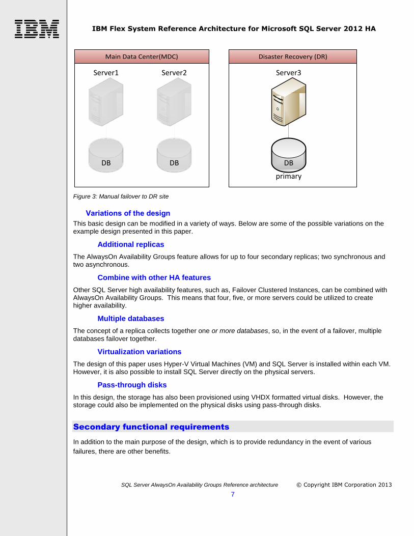
Disaster Recovery
If the Main Data Center has a catastrophic failure and all components fail, Server3 can be manually
configured to take over the role of updatable primary replica (shown in Figure 3). These would be pre-
planned steps, executed manually, after the failure of the Main Data Center has been confirmed. There is
some possibility of data loss, because the updates from Server2 (or Server 1) are asynchronously
transferred to Server3. Not all the updates made on Server1 may have been transferred to Server3 before
the Main Data Center failed. With the proper configuration, users connected to Server1 would be
automatically connected to Server3 the next time the application they are using attempts to connect to the
database. Users might experience two things in this scenario. First, if they entered data that was lost,
they would need to re-enter the lost data. Second, depending on how long the manual failover takes,
there may be a short, but noticeable period when their application is not available. After the failure of both
servers in the MDC the configuration is vulnerable to data loss and extended outage because only one
copy of the data and only one server have survived.
IBM Flex System Reference Architecture for Microsoft SQL Server 2012 HA
SQL Server AlwaysOn Availability Groups Reference architecture © Copyright IBM Corporation 2013
7
Main Data Center(MDC) Disaster Recovery (DR)
Server1
DB
Server2
DB
Server3
DB
primary
Figure 3: Manual failover to DR site
Variations of the design
This basic design can be modified in a variety of ways. Below are some of the possible variations on the example design presented in this paper.
Additional replicas
The AlwaysOn Availability Groups feature allows for up to four secondary replicas; two synchronous and two asynchronous.
Combine with other HA features
Other SQL Server high availability features, such as, Failover Clustered Instances, can be combined with AlwaysOn Availability Groups. This means that four, five, or more servers could be utilized to create higher availability.
Multiple databases
The concept of a replica collects together one or more databases, so, in the event of a failover, multiple databases failover together.
Virtualization variations
The design of this paper uses Hyper-V Virtual Machines (VM) and SQL Server is installed within each VM. However, it is also possible to install SQL Server directly on the physical servers.
Pass-through disks
In this design, the storage has also been provisioned using VHDX formatted virtual disks. However, the storage could also be implemented on the physical disks using pass-through disks.
Secondary functional requirements
In addition to the main purpose of the design, which is to provide redundancy in the event of various
failures, there are other benefits.

IBM Flex System Reference Architecture for Microsoft SQL Server 2012 HA
SQL Server AlwaysOn Availability Groups Reference architecture © Copyright IBM Corporation 2013
8
Read-able Secondaries
The databases connected to Server2 and Server3 can be used for read-only tasks, including reporting, database snapshots, database integrity checks and backups. Using this capability can reduce the performance load on the primary replica.
Rolling Upgrades
When upgrading the software or hardware on the servers, this can be done on the secondary servers first, and then after failing over the primary, on the (old) primary. This can reduce the users’ downtime during an upgrade.
Storage Migration
Like rolling upgrades, migrating the database to new storage can be done in a way that shortens downtime for the users, by first making the new copy a secondary replica, and then switching over to it when ready.
Multi-subnet Support
This solution paper demonstrates how the server in the DR site can be on a different subnet, which supports a remotely located disaster recovery site.
Licensing
You are allowed one Passive Secondary server that you do not need to license.
Automatic Page Repair
If SQL Server detects that a database page is corrupted, the replication topology will transfer a good copy of the page to the server with the corrupted copy and repair it.
Hardware Overview
This section describes the IBM hardware used for the reference architecture.
IBM PureFlex System and IBM Flex System
IBM PureFlex™ System is a comprehensive infrastructure system that provides an expert integrated
computing system. It combines servers, enterprise storage, networking, virtualization, and management
into a single structure. Its built-in expertise enables organizations to manage and deploy integrated
patterns of virtual and hardware resources through unified management. These systems are ideally suited
for customers who want a system that delivers the simplicity of an integrated solution while still able to
tune middleware and the runtime environment.
PureFlex System uses workload placement based on virtual machine compatibility and resource
availability. Using built-in virtualization across servers, storage, and networking, the infrastructure system
enables automated scaling of resources and true workload mobility.
PureFlex System has undergone significant testing and validation so that it can mitigate IT complexity
without compromising the flexibility to tune systems to the tasks businesses demand. By providing both
flexibility and simplicity, PureFlex System can provide extraordinary levels of IT control, efficiency, and
operating agility. This combination enables businesses to rapidly deploy IT services at a reduced cost.
Moreover, the system is built on decades of expertise. This expertise enables deep integration and central
management of the comprehensive, open-choice infrastructure system. It also dramatically cuts down on
the skills and training required for managing and deploying the system. The streamlined management

IBM Flex System Reference Architecture for Microsoft SQL Server 2012 HA
SQL Server AlwaysOn Availability Groups Reference architecture © Copyright IBM Corporation 2013
9
console makes it easy to use and provides a single point of control to manage your physical and virtual
resources (with KVM now. Hyper-V support is planned) for a vastly simplified management experience.
Figure 4: Front and rear view of the IBM Flex System Enterprise Chassis
The hardware used in this paper is IBM Flex System. IBM Flex System takes the components of the
PureFlex System and offers them à la carte allowing customers to custom-build their own infrastructure.
This gives customers to ability to purchase exactly what they need, with the option to move to the
PureFlex System at a later date.
IBM Flex System x240 Compute Node
IBM Flex System x240 Compute Node, an element of the Flex System, provides outstanding performance
for your mission-critical applications. Its energy-efficient design supports up to 16 processor cores and 768
GB of memory capacity in a package that is easy to service and manage. With outstanding computing
power per watt and the latest Intel® Xeon® processors, you can reduce costs while maintaining speed and
availability.
Highlights
Optimized for virtualization, performance and highly scalable networking
Embedded IBM Virtual Fabric allows IO flexibility
Designed for simplified deployment and management
To meet today’s complex and ever-changing business demands, the x240 compute node is optimized for
virtualization, performance and highly scalable I/O designed to run a wide variety of workloads. The IBM
Flex System x240 is available on either your PureFlex System or IBM Flex System solution.

IBM Flex System Reference Architecture for Microsoft SQL Server 2012 HA
SQL Server AlwaysOn Availability Groups Reference architecture © Copyright IBM Corporation 2013
10
Figure 5: IBM Flex System x240 Compute Node
More information about the IBM Flex System x240 compute node can be found in Resources at the end of
the document.
IBM Flex System V7000 Storage
IBM Flex System V7000 Storage® combines best-of-breed storage development with leading 1/10 Gb iSCSI, FCoE, or FC host interfaces and SAS/SSD drive technology. With its simple, efficient and flexible approach to storage, the Flex V7000 Storage is a cost-effective, complement to IBM Flex System. By offering substantial features at a price that fits most budgets, the Flex V7000 delivers superior price/performance ratios, functionality, scalability and ease of use for the mid-range storage user.
The Flex V7000 storage offers:
Automate and speed deployment with integrated storage for the IBM® PureFlex™ System or IBM Flex System™
Simplify management with an integrated, intuitive user interface for faster system accessibility
Reduce network complexity with FCoE and iSCSI connectivity
Store up to five times more active data in the same disk space using IBM Real-time Compression™
Virtualize third-party storage for investment protection of the current storage infrastructure
Optimize costs for mixed workloads, with up to 200 percent better performance with solid-state
drives (SSDs) using IBM System Storage® Easy Tier®1
Improve application availability and resource utilization for organizations of all sizes
Support growing business needs while controlling costs with clustered systems
Get innovative technology, open standards, excellent performance, and a broad portfolio of proven storage software, hardware and solutions offerings from IBM
IBM System Flex V7000 Storage (Figure 3) is well-suited for Microsoft virtualized cloud environments. The Flex V7000 Storage complements the IBM Flex System Enterprise Chassis, Flex CN4093 Converged Network switches, and x240 compute nodes in an end-to-end Microsoft Hyper-V private cloud solution by delivering proven disk storage in flexible, scalable configurations. Connecting optional EXP2500 enclosures to your Flex V7000 Storage can scale up to 240 SAS and SSD disks and up to 960 per clustered system. The Flex V7000 Storage has 8GB cache per controller and 16GB for the whole system.

IBM Flex System Reference Architecture for Microsoft SQL Server 2012 HA
SQL Server AlwaysOn Availability Groups Reference architecture © Copyright IBM Corporation 2013
11
The IBM System Flex V7000 Storage comes with advanced features such as System Storage Easy Tier, IBM Flashcopy, internal virtualization and thin provisioning, data migration, system clustering. Optional features include Remote Mirroring, Real-time Compression, and external virtualization.
Figure 6: IBM System Flex V7000 Storage
IBM Storwize V7000
The IBM Storwize V7000 disk system is a multi-faceted solution that consists of both hardware and
software components. The modular hardware enclosures include integrated drives of varying form factors,
including both hard disk drives (HDD) and solid-state drives (SSD). The solution also provides external
storage virtualization, making it possible to integrate with and manage heterogeneous storage along with
the Storwize V7000 storage as a single resource.
The Storwize V7000 system is designed to allow quick and efficient storage deployment, thanks to an
easy to use Graphical User Interface (GUI), integrated drives, and interoperability with nearly any back-
end SAN attached storage. The web-based GUI runs on the Storwize V7000 system so there is no longer
a separate console server or management software installation required.
Highlights
A single user interface to manage and virtualize internal and third-party storage that can
improve storage utilization
Built-in tiering and advanced replication functions are designed to improve performance
and availability without constant administration
Single user interface simplifies storage administration to allow your experts to focus on
innovation
Figure 7: IBM Storwize V7000 Control Enclosure

IBM Flex System Reference Architecture for Microsoft SQL Server 2012 HA
SQL Server AlwaysOn Availability Groups Reference architecture © Copyright IBM Corporation 2013
12
V7000 system details
V7000 enclosures support up to twenty-four 2.5-inch drives or up to twelve 3.5-inch drives. Control
enclosures contain drives, redundant dual-active intelligent controllers, and dual power supplies, batteries
and cooling components. Expansion enclosures contain drives, switches, power supplies and cooling
components. You can attach up to nine expansion enclosures to a control enclosure supporting up to 240
drives. The system also supports intermixing 3.5-inch and 2.5-inch type controller and expansion
enclosures.
Key system characteristics are:
Internal storage capacity: up to 36 TB of physical storage per enclosure
Drives: SAS HDDs, near-line SAS HDDs and solid-state drives can be mixed in an
enclosure to give you extraordinary flexibility
Cache memory: 16 GB cache memory (8 GB per controller) as a base feature—designed
to improve performance and availability
More information about the Storwize V7000 can be found in Resources at the end of the document.
IBM Storwize V3700
IBM Storwize V3700 is an entry-level addition to the IBM Storwize family of disk systems, and delivers efficient configurations specifically designed to meet the needs of small and midsize businesses. The system shares the same integrated easy-to use web interface as the XIV and other Storwize systems. The internal disk storage virtualization enables rapid, flexible provisioning and simple configuration changes. IBM Storwize V3700 offers advanced hardware and software capabilities usually found in more expensive systems, including:
Redundant, battery backed dual controllers
Up to 16GB cache, 8 per controller (4GB per controller standard)
Redundant, hot-swappable power supplies and fans
Dual-port, hot-swappable 6 Gb SAS disk drives
Support for RAID 0,1,5,6 and 10 and up to 180 TB of capacity
1 Gb iSCSI, optional 10 Gb iSCSI/Fibre Channel over Ethernet (FCoE) or 8 Gb Fibre Channel Disk storage scales up to 120 2.5-inch disk drives or 60 3.5-inch disk drives with four expansion units. Each unit is a packaged in a compact 2U 19-inch rack-mount enclosure. The modular design allows a business to start small and hot add additional enclosures as needed and without any downtime. The system also supports SSD drives and IBM Easy Tier® automated hot data migration as an optional upgrade feature. As with earlier Storwize systems, advanced data protection and migration features include:
Non-disruptive data migration
Internal virtualization and thin provisioning
Remote mirroring
Integrated IBM FlashCopy® snapshot technology
Reduce power consumption with energy-saving features
Advanced upgrades like FlashCopy (more targets) and Easy Tier

IBM Flex System Reference Architecture for Microsoft SQL Server 2012 HA
SQL Server AlwaysOn Availability Groups Reference architecture © Copyright IBM Corporation 2013
13
Figure 8: IBM Storwize V3700 Control Enclosure
IBM Flex System EN4093 Switches
The IBM Flex System™ Fabric EN4093 and EN4093R 10Gb Scalable Switches provide unmatched
scalability and performance, while also delivering innovations to help address a number of networking
concerns today and providing capabilities that will help you prepare for the future. These switches are
capable of supporting up to sixty-four 10 Gb Ethernet connections while offering Layer 2/3 switching. They
are designed to install within the I/O module bays of the IBM Flex System Enterprise Chassis. These
switches can help clients migrate to a 10 Gb or 40 Gb Ethernet infrastructure and offer virtualization
features like Virtual Fabric and VMready®, plus the ability to work with IBM® Distributed Virtual Switch
5000V.
Figure 9: IBM Flex EN4093 Switch
IBM Flex System FC3171 Switches
The IBM Flex System™ FC3171 8Gb SAN Switch is a full-fabric Fibre Channel component with expanded
functionality. The SAN switch supports high speed traffic processing for IBM Flex System configurations
and offers scalability in external SAN size and complexity, and enhanced systems management
capabilities. The IBM Flex System FC3171 8 Gb Pass-thru supports a fully interoperable solution for
seamless integration of the Fibre Channel initiators to an existing fabric. The pass-thru module uses
industry-standard N_Port ID virtualization (NPIV) technology to provide a cost-effective connectivity
solution for the IBM Flex System chassis.
LOG
TX RX
16
LOG
TX RX
15
LOG
TX RX
17
LOG
TX RX
18
LOG
TX RX
19
LOG
TX RX
0
Mg
mt
Link
Tx/R
x
8Gb
FULL
FABR
IC
Figure 10: IBM Flex FC3171 Switch
Architectural overview
The architectural diagram (Figure 11) shows a high-level view of the complete high availability solution.

IBM Flex System Reference Architecture for Microsoft SQL Server 2012 HA
SQL Server AlwaysOn Availability Groups Reference architecture © Copyright IBM Corporation 2013
14
WAN
FLEX (DR)
FLEX (MDC)
Hyper-V
Hyper-V
Hyper-V
Windows Failover Cluster
VM VM
VM
SQL Server AlwaysOn Availability Group
SQL SQL
SQL
V7000SAN Array
VMDX
DB
V3700SAN Array
VMDX
DB
FLEX V7000SAN Array
VMDX
DB
Users
Figure 11: Complete high availability solution architecture
The solution is composed of two IBM Flex Systems (each with an external storage subsystem), which are
located in two separate data centers; the Main Data Center (MDC) and the Disaster Recovery (DR) site.
The two data centers have connectivity across a Wide Area Network (WAN). The Flex System in the MDC
has two physical servers (x240 compute nodes) and one integrated Flex System V7000 Storage unit. One
x240 is connected to the Flex System V7000 Storage unit. The other x240 is connected to the external
IBM Storwize V7000 Storage unit. The Flex System in the DR site has one physical server (x240 compute
node). That x240 is connected to the external IBM Storwize V3700 Storage unit. Each x240 compute
node is running Windows Server 2012 with the Hyper-V role enabled. A single virtual machine (VM) has
been created on each server. Windows Server 2012 and a standalone SQL Server 2012 has been
installed in each VM. The virtual machines have been configured in a Windows Server Failover Cluster
with no shared storage. This is a scalable solution and more SQL Servers and VMs can be created
depending on resources available. More x240 compute nodes can be added to the configuration also.
The disk space for the files used in the SQL Server databases begin as physical arrays, and then physical
volumes, created on each of the dedicated storage units. These volumes are then presented to the
Windows Hyper-V operating system and formatted as VHDX files. The VHDX files are attached to the
VMs, which see them as volumes presented to the Windows operating system inside the VM. It is on
those volumes that the SQL Server databases are created.
IBM Flex System Reference Architecture for Microsoft SQL Server 2012 HA
SQL Server AlwaysOn Availability Groups Reference architecture © Copyright IBM Corporation 2013
15
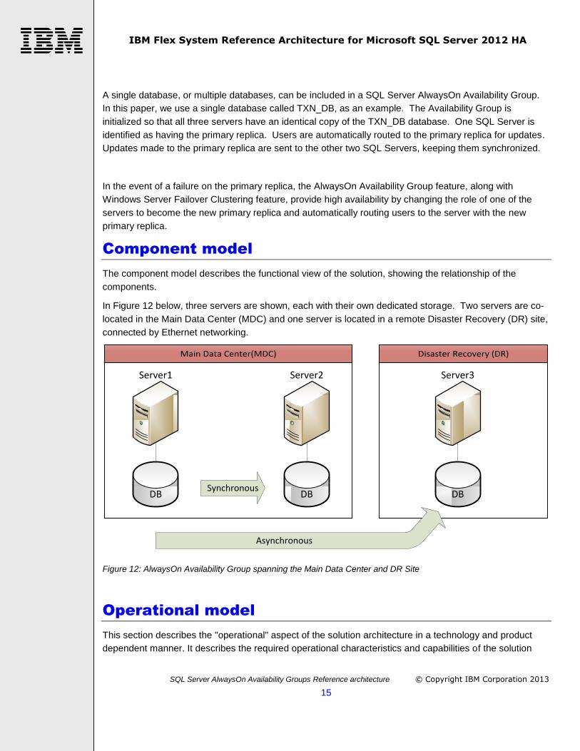
A single database, or multiple databases, can be included in a SQL Server AlwaysOn Availability Group.
In this paper, we use a single database called TXN_DB, as an example. The Availability Group is
initialized so that all three servers have an identical copy of the TXN_DB database. One SQL Server is
identified as having the primary replica. Users are automatically routed to the primary replica for updates.
Updates made to the primary replica are sent to the other two SQL Servers, keeping them synchronized.
In the event of a failure on the primary replica, the AlwaysOn Availability Group feature, along with
Windows Server Failover Clustering feature, provide high availability by changing the role of one of the
servers to become the new primary replica and automatically routing users to the server with the new
primary replica.
Component model
The component model describes the functional view of the solution, showing the relationship of the
components.
In Figure 12 below, three servers are shown, each with their own dedicated storage. Two servers are co-
located in the Main Data Center (MDC) and one server is located in a remote Disaster Recovery (DR) site,
connected by Ethernet networking.
Main Data Center(MDC) Disaster Recovery (DR)
Server1
DB
Server2
DB
Server3
DBSynchronous
Asynchronous
Figure 12: AlwaysOn Availability Group spanning the Main Data Center and DR Site
Operational model
This section describes the "operational" aspect of the solution architecture in a technology and product
dependent manner. It describes the required operational characteristics and capabilities of the solution

IBM Flex System Reference Architecture for Microsoft SQL Server 2012 HA
SQL Server AlwaysOn Availability Groups Reference architecture © Copyright IBM Corporation 2013
16
architecture and represents, at an architectural level, the network of computer systems and their
associated peripherals, together with the systems software, middleware, and application software that they
run in order to support the users of the system.
It is useful to view this solution in three layers, each built upon the previous layer: Physical, Virtual and
SQL Server.
Physical Layer – this includes the physical hardware; Flex chassis, servers, switches, storage
units, the networking configuration between the hardware components, as well as the operating
systems installed on the hardware and the storage volumes created.
Virtual Layer – this includes the virtual machines (VMs), the virtual disks, the networks created
between them, and the Windows Server Failover Cluster created between the VMs.
SQL Server Layer – this includes the SQL Server instances and the AlwaysOn Availability Group
configuration, the replication topology created between them, and the user databases.
Physical Layer
We begin with a discussion of the placement of the hardware in the racks. There will be one rack in each
data center – the Main Data Center (MDC) and the Disaster Recovery (DR) site. Please refer to Figure 13
Physical layer rack view. One Flex chassis and one external storage unit is placed in each rack. In the
MDC, an integrated Flex V7000 storage unit, two x240 compute nodes, two 10 Gb Ethernet switches and
two 8 Gb Fibre Channel switches are placed in the Flex chassis. In the DR site, one x240 compute node,
two 10 Gb Ethernet switches and two 8 Gb Fibre Channel switches are placed in the Flex chassis.
The physical location of the components in the chassis determines which internal connections are made
with the switches. For example, the adapter in IO Module 1 in the x240 connects to switch bays 1 and 2
(which are in positions 1 and 3 viewed from the back, from left to right). In this solution, the Ethernet
adapter is installed in IO Module 1 and the Ethernet switches in bays 1 and 2, so that the Ethernet
components are connected internally by the Flex infrastructure. Likewise, the Fibre Channel adapter is
installed in IO Module 2 in the x240 and the Fibre Channel switches are installed in switch bays 3 and 4
(which are in positions 2 and 4 viewed from the back, from left to right), so that the Fibre Channel
components are connected internally in the same way as the Ethernet components.
In addition, the placement of the x240s and integrated Flex V7000 (V7000A) in the Flex chassis
determines which internal switch ports are used. For example, the x240 placed in node 1, called BT101,
will utilize internal switch port 1 on each of the 4 switches.
We will make use of Windows Ethernet adapter teaming on the x240, which will require an ISL (inter-
switch link) configuration between the two Ethernet switches within each Flex chassis. A Virtual Link
Aggregation Group (VLAG), to support the team, should be configured on the 2 switches [refer to page 19
“Grant Privilege and Enter Configuration mode” of Hyper-V Fast Track Reference Architecture for IBM
Flex System]. The ISL requires two physical Ethernet cables between the switches. In addition, two
physical Ethernet cables are required to connect the Flex chassis to the WAN (wide area network).
The external storage unit (V7000B in the MDC and the V3700C in the DR site) requires four external fibre
cable connections to the fibre channel switches. The integrated Flex V7000 (V7000A) does not require
external fibre cables as those connections are made using the internal infrastructure of the Flex chassis.

IBM Flex System Reference Architecture for Microsoft SQL Server 2012 HA
SQL Server AlwaysOn Availability Groups Reference architecture © Copyright IBM Corporation 2013
17
The storage on the external Storwize V7000 (V7000B) will be zoned and dedicated to the x240 named
BT101. The storage on the integrated Flex V7000 (V7000A) will be zoned and dedicated to the x240
named BT103. The storage on the external Storwize V3700 (V7000C) will be zoned and dedicated to the
x240 named BT105. Dedicating each storage unit to one x240 provides high availability and performance.

IBM Flex System Reference Architecture for Microsoft SQL Server 2012 HA
SQL Server AlwaysOn Availability Groups Reference architecture © Copyright IBM Corporation 2013
18
Physical deployment rack view
WAN
Flex System Enterprise
1
3
5
7
9
11
13
2
4
6
8
10
12
14
x240
0
1
241
System Storage
45
41
CMM1
CMM2
LINK
TX/RX
CMMBay
6 3
10 3
4
5
6
1
2
3
PowerSupplyBays
54
3
2
1
109
8
7
6
FanBays
6
5
4
3
2
1
I/O BayI/O BayI/O BayI/O Bay
PowerSupplyBay
FanBay
PowerSupplyBay
PowerSupplyBay
PowerSupplyBay
PowerSupplyBay
PowerSupplyBay
FanBay
FanBay
FanBay
FanBay
FanBay
FanBay
FanBay
21
1 2
CAUTION
3
1
4
2
Disconnect allsupply power forcomplete isolation
Disconnect allsupply power forcomplete isolation
4
2
3
1
CAUTION
3
1
4
2
4
2
3
1
CAUTION
Disconnect allsupply power forcomplete isolation
CAUTION
Disconnect allsupply power forcomplete isolation
2
3
1
4
21
1 2
2 1
1
3
2
412
2 14 3 2 14 3
21 4321 43
12
1 2
LOGTXRX
16
LOGTXRX
15
LOGTXRX
17
LOGTXRX
18
LOGTXRX
19
LOGTXRX
0
Mgmt
Link
Tx/Rx
8Gb FULL FABRIC
LOGTXRX
16
LOGTXRX
15
LOGTXRX
17
LOGTXRX
18
LOGTXRX
19
LOGTXRX
0
Mgmt
Link
Tx/Rx
8Gb FULL FABRIC
Link
Tx/Rx6
Link
Tx/Rx5
Link
Tx/Rx2
Link
Tx/Rx1
Link
Tx/Rx4
Link
Tx/Rx3
Link
Tx/Rx8
Link
Tx/Rx7
Link
Tx/Rx10
Link
Tx/Rx9
Link
Tx/Rx12
Link
Tx/Rx11
Link
Tx/Rx14
Link
Tx/Rx13
Link
Tx/Rx15 16
Link
Tx/Rx17 18
15
15
171618
10 Gb
40 Gb
Link
Tx/Rx19 20
21 22
19
19
212022
10 Gb
40 Gb
Mgmt
Link
Tx/Rx
Link
Tx/Rx6
Link
Tx/Rx5
Link
Tx/Rx2
Link
Tx/Rx1
Link
Tx/Rx4
Link
Tx/Rx3
Link
Tx/Rx8
Link
Tx/Rx7
Link
Tx/Rx10
Link
Tx/Rx9
Link
Tx/Rx12
Link
Tx/Rx11
Link
Tx/Rx14
Link
Tx/Rx13
Link
Tx/Rx15 16
Link
Tx/Rx17 18
15
15
171618
10 Gb
40 Gb
Link
Tx/Rx19 20
21 22
19
19
212022
10 Gb
40 Gb
Mgmt
Link
Tx/Rx
Flex x240 compute
node BT105
V3700 storage
controller V3700C
Flex FC3171 8Gb
SAN Switch
Flex FC3171 8Gb
SAN Switch
Flex EN4093 10Gb
Ethernet Switch
Flex EN4093 10Gb
Ethernet Switch
Front view Back view
Flex System Enterprise
1
3
5
7
9
11
13
2
4
6
8
10
12
14
Flex System V7000
Control Module
1
1-24
Control Module
1
x240
0
1
x240
0
1
241
System Storage
45
41
CMM1
CMM2
LINK
TX/RX
CMMBay
6 3
10 3
4
5
6
1
2
3
PowerSupplyBays
54
3
2
1
109
8
7
6
FanBays
6
5
4
3
2
1
I/O BayI/O BayI/O BayI/O Bay
PowerSupplyBay
FanBay
PowerSupplyBay
PowerSupplyBay
PowerSupplyBay
PowerSupplyBay
PowerSupplyBay
FanBay
FanBay
FanBay
FanBay
FanBay
FanBay
FanBay
21
1 2
CAUTION
3
1
4
2
Disconnect allsupply power forcomplete isolation
Disconnect allsupply power forcomplete isolation
4
2
3
1
CAUTION
3
1
4
2
4
2
3
1
CAUTION
Disconnect allsupply power forcomplete isolation
CAUTION
Disconnect allsupply power forcomplete isolation
2
3
1
4
21
1 2
2 1
1
3
2
412
2 14 3 2 14 3
21 4321 43
12
1 2
LOGTXRX
16
LOGTXRX
15
LOGTXRX
17
LOGTXRX
18
LOGTXRX
19
LOGTXRX
0
Mgmt
Link
Tx/Rx
8Gb FULL FABRIC
LOGTXRX
16
LOGTXRX
15
LOGTXRX
17
LOGTXRX
18
LOGTXRX
19
LOGTXRX
0
Mgmt
Link
Tx/Rx
8Gb FULL FABRIC
Link
Tx/Rx6
Link
Tx/Rx5
Link
Tx/Rx2
Link
Tx/Rx1
Link
Tx/Rx4
Link
Tx/Rx3
Link
Tx/Rx8
Link
Tx/Rx7
Link
Tx/Rx10
Link
Tx/Rx9
Link
Tx/Rx12
Link
Tx/Rx11
Link
Tx/Rx14
Link
Tx/Rx13
Link
Tx/Rx15 16
Link
Tx/Rx17 18
15
15
171618
10 Gb
40 Gb
Link
Tx/Rx19 20
21 22
19
19
212022
10 Gb
40 Gb
Mgmt
Link
Tx/Rx
Link
Tx/Rx6
Link
Tx/Rx5
Link
Tx/Rx2
Link
Tx/Rx1
Link
Tx/Rx4
Link
Tx/Rx3
Link
Tx/Rx8
Link
Tx/Rx7
Link
Tx/Rx10
Link
Tx/Rx9
Link
Tx/Rx12
Link
Tx/Rx11
Link
Tx/Rx14
Link
Tx/Rx13
Link
Tx/Rx15 16
Link
Tx/Rx17 18
15
15
171618
10 Gb
40 Gb
Link
Tx/Rx19 20
21 22
19
19
212022
10 Gb
40 Gb
Mgmt
Link
Tx/Rx
Flex x240 compute
node BT101
Flex x240 compute
node BT103
Flex V7000 storage
node V7000A
V7000 storage
controller V7000B
Flex FC3171 8Gb
SAN Switch
Flex FC3171 8Gb
SAN Switch
Flex EN4093 10Gb
Ethernet Switch
Flex EN4093 10Gb
Ethernet Switch
Front view Back view
Main Data Center (MDC)
Disaster Recovery (DR)
Ethernet
Fibre
Figure 13: Physical layer rack view

IBM Flex System Reference Architecture for Microsoft SQL Server 2012 HA
SQL Server AlwaysOn Availability Groups Reference architecture © Copyright IBM Corporation 2013
19
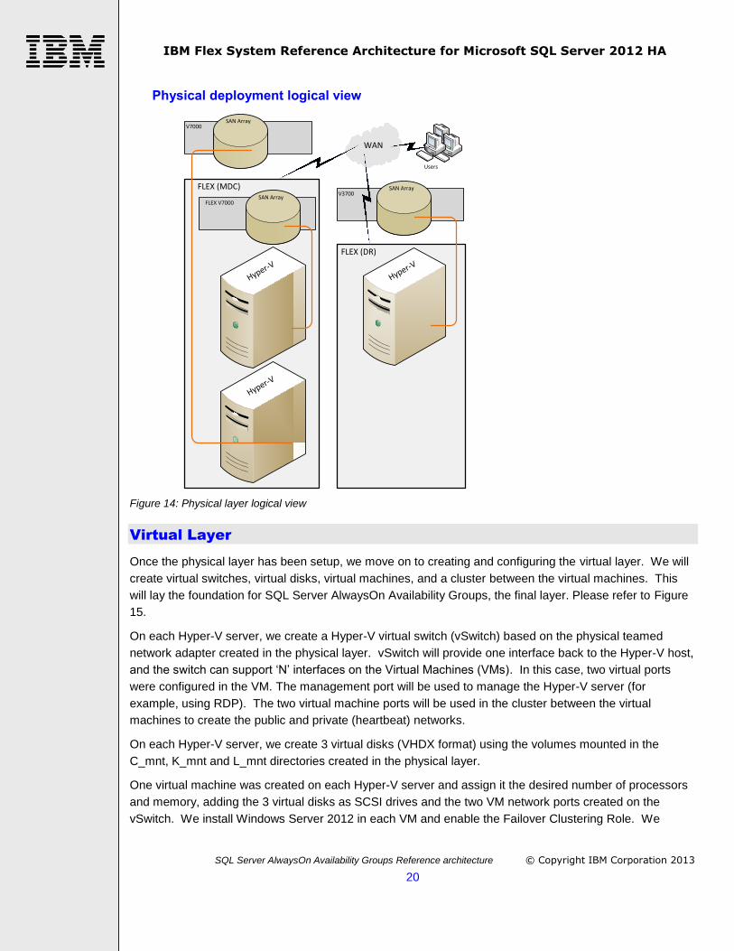
Next, we discuss the configuration of the physical hardware, such as, installing the operating system and
creating the SAN volumes. Please refer to Figure 14.
We install Windows Server 2012 on each x240 compute node (on a RAID1 mirror between the two local
spinning disks) and enable the Hyper-V role. We name these servers BT101, BT103 and BT105. The first
two are in the MDC and the last one is in the DR site. We are not going to configure Windows Server
Failover Clustering (WSFC) on the Hyper-V servers. (However, we will be using WSFC on the virtual
machines, as described below.) We use the new NIC Teaming feature in Windows Server 2012, which
allows two or more network adapters to behave as a single, virtual device. This improves the reliability of
the networking subsystem – if one NIC dies, the other continues to function – and allows the bandwidth
available to each to be pooled for greater total network throughput for SQL Server data.
The physical volume configuration is highly dependent on an organization’s requirements for space and
performance. The client may wish to increase the number of volumes, for example, if there are more
databases involved. We describe the sample configuration created for this paper.
Each storage unit is configured identically. Three physical volumes were created on each storage unit.
(Note that Figure 14 shows a single SAN array physical volume per storage unit for simplicity.) The three
volumes are mounted under the local C: drive (in C_mnt, K_mnt and L_mnt directories) of the Hyper-V
server. They will be provisioned for a virtual machine operating system disk (C drive), a database data
disk (K drive) and a database log disk (L drive), respectively. In this solution, the operating system disk
(C_mnt) is on a volume of 6 spindles in a RAID10. The database (K_mnt) and log (L_mnt) disks are on
dedicated volumes of 8 spindles each, in a RAID10. It is a SQL Server best practice to place the database
and log files on separate dedicated volumes. This improves both availability and performance. Two
spindles are assigned as hot spares.
Each set of three physical volumes is mapped to and mounted on the corresponding Hyper-V server
(meaning the one zoned on the fibre channel switch).
IBM Flex System Reference Architecture for Microsoft SQL Server 2012 HA
SQL Server AlwaysOn Availability Groups Reference architecture © Copyright IBM Corporation 2013
20
Physical deployment logical view
WAN
FLEX (DR)
FLEX (MDC)
Hyper-V
Hyper-V
Hyper-V
V7000SAN Array
V3700SAN Array
FLEX V7000SAN Array
Users
Figure 14: Physical layer logical view
Virtual Layer
Once the physical layer has been setup, we move on to creating and configuring the virtual layer. We will
create virtual switches, virtual disks, virtual machines, and a cluster between the virtual machines. This
will lay the foundation for SQL Server AlwaysOn Availability Groups, the final layer. Please refer to Figure
15.
On each Hyper-V server, we create a Hyper-V virtual switch (vSwitch) based on the physical teamed
network adapter created in the physical layer. vSwitch will provide one interface back to the Hyper-V host,
and the switch can support ‘N’ interfaces on the Virtual Machines (VMs). In this case, two virtual ports
were configured in the VM. The management port will be used to manage the Hyper-V server (for
example, using RDP). The two virtual machine ports will be used in the cluster between the virtual
machines to create the public and private (heartbeat) networks.
On each Hyper-V server, we create 3 virtual disks (VHDX format) using the volumes mounted in the
C_mnt, K_mnt and L_mnt directories created in the physical layer.
One virtual machine was created on each Hyper-V server and assign it the desired number of processors
and memory, adding the 3 virtual disks as SCSI drives and the two VM network ports created on the
vSwitch. We install Windows Server 2012 in each VM and enable the Failover Clustering Role. We

IBM Flex System Reference Architecture for Microsoft SQL Server 2012 HA
SQL Server AlwaysOn Availability Groups Reference architecture © Copyright IBM Corporation 2013
21
mount the C_mnt volume to the C: drive and the K_mnt and L_mnt volumes to the K: and L: drives,
respectively, inside the VM. We assign the static IP addresses to the VM network interfaces, one for the
Public network and one for the Private network. Note this solution supports multiple subnets. We name
the VMs VM101 (on BT101), VM103 (on BT103) and VM105 (on BT105). We join the VMs to the domain.
We create the Windows Server Failover Cluster between the three VMs. Please not that this cluster has
no shared storage. It should have multiple static IP addresses, if the VMs are on different subnets.
For details on establishing the cluster quorum model, including using a file share, and voting, please see:
Building a High Availability and Disaster Recovery Solution using AlwaysOn Availability Groups
Virtual deployment
WAN
FLEX (DR)
FLEX (MDC)
Hyper-V
Hyper-V
Hyper-V
Windows Failover Cluster
VM VM
VM
V7000SAN Array
VMDX
V3700SAN Array
VMDXFLEX V7000
SAN Array
VMDX
Users
Figure 15: Virtual layer
SQL Server Layer
After the virtual layer has been configured, we create the final layer based on SQL Server and the
AlwaysOn Availability Groups feature. In this step, we will install SQL Server, configure the AlwaysOn
Availability Groups feature and assign a sample database, TXN_DB, to an availability group for high
availability protection. Please refer to Figure 16.
We install a default standalone SQL Server 2012 Enterprise Edition Instance in each VM. Please note
that this is not a clustered SQL Server Instance.

IBM Flex System Reference Architecture for Microsoft SQL Server 2012 HA
SQL Server AlwaysOn Availability Groups Reference architecture © Copyright IBM Corporation 2013
22
We place our user database, TXN_DB, on the K: and L: drives in VM101, which will be our primary replica.
Then we backup the database and restore it (using the NORECOVERY option) on the other two VMs,
VM103 and VM105, which will be our secondary replicas.
We create the Availability Group for the TXN_DB database, making VM101 the primary replica, making
VM103 the synchronous secondary with automatic failover and making VM105 (in the DR site) the
asynchronous secondary with manual failover. We create an Availability Group Listener, called
TXN_AG_Listener, giving two static IP addresses (one for each subnet), which provides a DNS name
which user applications can connect to and be automatically routed to the primary replica, regardless of
which subnet the primary replica is running on.
SQL Server AlwaysOn Availability Group deployment
WAN
FLEX (DR)
FLEX (MDC)
Hyper-V
Hyper-V
Hyper-V
Windows Failover Cluster
VM VM
VM
SQL Server AlwaysOn Availability Group
SQL SQL
SQL
V7000SAN Array
VMDX
DB
V3700SAN Array
VMDX
DB
FLEX V7000SAN Array
VMDX
DB
Users
Figure 16: SQL Server AlwaysOn Availability Group layer
Deployment considerations
This section describes noteworthy deployment considerations. In particular, it describes how features of
the Flex System are used in the solution deployment across data centers for high availability.
This section also includes a high-level overview of the requirements the customer’s IT environment must
address for deploying this reference architecture.

IBM Flex System Reference Architecture for Microsoft SQL Server 2012 HA
SQL Server AlwaysOn Availability Groups Reference architecture © Copyright IBM Corporation 2013
23
Systems management
Systems management for this solution uses the native Windows Server and SQL Server management
tools.
Server / Compute Nodes
The compute nodes are the Flex System x240 compute nodes. Each x240 has 2 processors, 96 GB of
memory, two 2.5” spinning disks in a RAID1 pair, a dual port 10Gb Ethernet adapter in IO Module 1 and a
dual port 8 Gb fibre channel adapter in IO Module 2. Processor speed and number of cores, and amount
of memory should be selected based on the customer’s requirements.
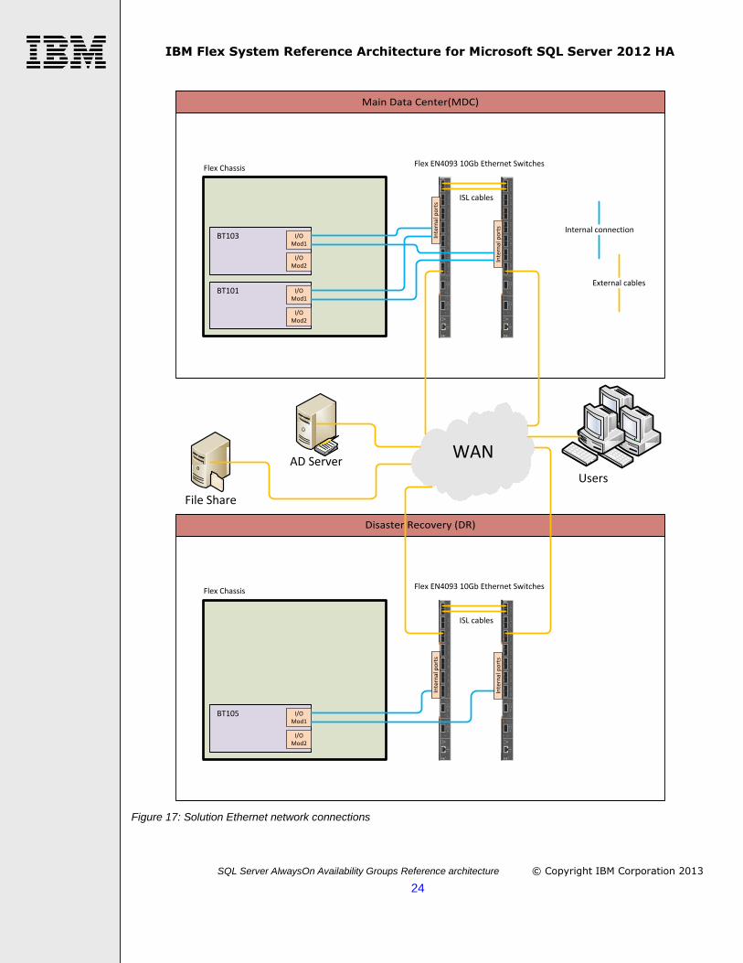
Networking
This section describes the Ethernet network topology. Figure 17 Ethernet network connections shows the
connections between the servers, switches, and the wide area network (WAN). Each x240 compute node
has two Ethernet connections from the EN4132 2-port 10Gb Ethernet adapter in IO Module 1, one to each
Ethernet switch for redundancy and increased performance. These connections are made via the Flex
infrastructure, not by using external cables. Two external cables connect the two Ethernet switches within
a single Flex chassis to create a bonded (LACP) Inter Switch Link (ISL). The ISL link allows the two
Ethernet ports in each x240 to be teamed efficiently. The teaming is done using LACP for active/active
utilizations of the links. Additional Ethernet cables uplink the switches into the WAN infrastructure. The
WAN, which is unique to each customer, provides connectivity between the Flex chassis over a
geographic distance. The WAN also connects to the file share (needed for the quorum in Windows Server
Failover Cluster), to the customer’s Active Directory servers (required for the Windows Server Failover
Cluster) and to the users for accessing the application servers using the SQL Server databases.
IBM Flex System Reference Architecture for Microsoft SQL Server 2012 HA
SQL Server AlwaysOn Availability Groups Reference architecture © Copyright IBM Corporation 2013
24
Main Data Center(MDC)
Disaster Recovery (DR)
WAN
Flex Chassis
BT103 I/O Mod1
Link
Tx/Rx6
Link
Tx/Rx5
Link
Tx/Rx2
Link
Tx/Rx1
Link
Tx/Rx4
Link
Tx/Rx3
Link
Tx/Rx8
Link
Tx/Rx7
Link
Tx/Rx10
Link
Tx/Rx9
Link
Tx/Rx12
Link
Tx/Rx11
Link
Tx/Rx14
Link
Tx/Rx13
Link
Tx/Rx15 16
Link
Tx/Rx17 18
15
15
171618
10 Gb
40 Gb
Link
Tx/Rx19 20
21 22
19
19
212022
10 Gb
40 Gb
Mgmt
Link
Tx/Rx
Link
Tx/Rx6
Link
Tx/Rx5
Link
Tx/Rx2
Link
Tx/Rx1
Link
Tx/Rx4
Link
Tx/Rx3
Link
Tx/Rx8
Link
Tx/Rx7
Link
Tx/Rx10
Link
Tx/Rx9
Link
Tx/Rx12
Link
Tx/Rx11
Link
Tx/Rx14
Link
Tx/Rx13
Link
Tx/Rx15 16
Link
Tx/Rx17 18
15
15
171618
10 Gb
40 Gb
Link
Tx/Rx19 20
21 22
19
19
212022
10 Gb
40 Gb
Mgmt
Link
Tx/Rx
ISL cables
Flex EN4093 10Gb Ethernet Switches
I/O Mod2
BT101 I/O Mod1
I/O Mod2
Flex Chassis
Link
Tx/Rx6
Link
Tx/Rx5
Link
Tx/Rx2
Link
Tx/Rx1
Link
Tx/Rx4
Link
Tx/Rx3
Link
Tx/Rx8
Link
Tx/Rx7
Link
Tx/Rx10
Link
Tx/Rx9
Link
Tx/Rx12
Link
Tx/Rx11
Link
Tx/Rx14
Link
Tx/Rx13
Link
Tx/Rx15 16
Link
Tx/Rx17 18
15
15
171618
10 Gb
40 Gb
Link
Tx/Rx19 20
21 22
19
19
212022
10 Gb
40 Gb
Mgmt
Link
Tx/Rx
Link
Tx/Rx6
Link
Tx/Rx5
Link
Tx/Rx2
Link
Tx/Rx1
Link
Tx/Rx4
Link
Tx/Rx3
Link
Tx/Rx8
Link
Tx/Rx7
Link
Tx/Rx10
Link
Tx/Rx9
Link
Tx/Rx12
Link
Tx/Rx11
Link
Tx/Rx14
Link
Tx/Rx13
Link
Tx/Rx15 16
Link
Tx/Rx17 18
15
15
171618
10 Gb
40 Gb
Link
Tx/Rx19 20
21 22
19
19
212022
10 Gb
40 Gb
Mgmt
Link
Tx/Rx
ISL cables
Flex EN4093 10Gb Ethernet Switches
BT105 I/O Mod1
I/O Mod2
File Share
AD Server
Internal connection
External cables
Users
Inte
rnal
po
rts
Inte
rnal
po
rts
Inte
rnal
po
rts
Inte
rnal
po
rts
Figure 17: Solution Ethernet network connections

IBM Flex System Reference Architecture for Microsoft SQL Server 2012 HA
SQL Server AlwaysOn Availability Groups Reference architecture © Copyright IBM Corporation 2013
25
Storage integration
This section describes the storage fibre channel network topology. Figure 18 shows the connections
between the servers, switches, and the storage units. Each x240 compute node has two fibre channel
connections from the F3172 2-port 8Gb FC adapter in IO Module 2, one to each fibre channel switch for
redundancy. These connections are made via the Flex infrastructure, not by using external fibre cables.
The integrated Flex V7000 (V7000A) is also connected to the fibre channel switches via the Flex
infrastructure. The external storage units (V7000B and V3700C) are connected to their respective Flex
chassis via external fibre cables to the fibre channel switches as shown. The effect of this topology is for
each server to be connected to its own dedicated storage, with redundancy, including redundant switches.

IBM Flex System Reference Architecture for Microsoft SQL Server 2012 HA
SQL Server AlwaysOn Availability Groups Reference architecture © Copyright IBM Corporation 2013
26
Main Data Center(MDC)
Disaster Recovery (DR)
Flex Chassis
BT103 I/O Mod1
Flex FC3171 8Gb Switches
I/O Mod2
BT101 I/O Mod1
I/O Mod2
Internal connection
External cables
LOGTXRX
16
LOGTXRX
15
LOGTXRX
17
LOGTXRX
18
LOGTXRX
19
LOGTXRX
0
Mgmt
Link
Tx/Rx
8Gb FULL FABRIC
LOGTXRX
16
LOGTXRX
15
LOGTXRX
17
LOGTXRX
18
LOGTXRX
19
LOGTXRX
0
Mgmt
Link
Tx/Rx
8Gb FULL FABRIC
V7000A
Node1 Node2
Inte
rnal
po
rts
Inte
rnal
po
rts
V7000B
Node1 Node2
Flex Chassis
Flex FC3171 8Gb Switches
BT105 I/O Mod1
I/O Mod2
LOGTXRX
16
LOGTXRX
15
LOGTXRX
17
LOGTXRX
18
LOGTXRX
19
LOGTXRX
0
Mgmt
Link
Tx/Rx
8Gb FULL FABRIC
LOGTXRX
16
LOGTXRX
15
LOGTXRX
17
LOGTXRX
18
LOGTXRX
19
LOGTXRX
0
Mgmt
Link
Tx/Rx
8Gb FULL FABRIC
Inte
rnal
po
rts
Inte
rnal
po
rts
V3700C
Node1 Node2
Figure 18: Solution storage fibre channel network connections
Performance Considerations
AlwaysOn Availability Groups are sensitive to Ethernet network bandwidth, because potentially high
volume updates on the primary replica can be sent over Ethernet to the secondary replicas. This solution
provides very high network bandwidth using the 20 Gb/s aggregated teamed network adapters. Updating

IBM Flex System Reference Architecture for Microsoft SQL Server 2012 HA
SQL Server AlwaysOn Availability Groups Reference architecture © Copyright IBM Corporation 2013
27
workload performance on the primary replica can be improved by offloading read-only workloads (such as
backup and reporting) to the secondary replicas. Create fixed sized VHDX disks for best storage
performance. Chose 64K as the NTFS cluster (Allocation Unit) size for the volumes used by SQL Server.
Another improvement in performance could be realized by doing away with the virtual machines and
installing SQL Server on the physical servers. Both of these options trade off performance with the
manageability benefits of virtualization.
Best practices and limitations
In this solution, the unit of failover is the availability group (a group of user databases). SQL Server Agent
jobs, logins, linked servers, and other objects that are stored outside of the availability databases do not
fail over with the availability group. Consider the use of contained databases for containing logins that fail
over across the availability replicas. For other objects outside of the user database such as SQL Server
Agent jobs, linked servers, and SQL Server Integration Services packages, you will need to take additional
synchronization steps across the SQL Server instances.
When conducting a planned failover to the DR site, or when failing back to the MDC, put the secondary
replica on VM105 in synchronous mode, temporarily. Then the failover can proceed.
Once the availability group is operational, set up monitoring to provide alerts when the health of the
availability group declines.
Set up database and log backup preferences, so that backups are taken regardless of the state of the
availability group.
Other considerations
When deploying the solution, here are a couple of alternatives. Consider installing SQL Server from the
command line, rather than via the GUI. After the first VM, VM101, has been created, sysprep it and copy
the VM image to the other two servers. This works even if SQL Server is installed (a new feature of SQL
Server 2012).

IBM Flex System Reference Architecture for Microsoft SQL Server 2012 HA
SQL Server AlwaysOn Availability Groups Reference architecture © Copyright IBM Corporation 2013
28
About the author
Michael Lawson works at the IBM Center for Microsoft Technologies in Kirkland, Washington (just 5 miles
from the Microsoft main campus). He also has an office on the Microsoft main campus in Redmond,
Washington to facilitate close collaboration with Microsoft.
Michael has been an IBM employee since 1999 and has specialized in SQL Server including data
warehousing, high availability, performance testing, and virtualization.
Acknowledgements
The author would like to thank the following people for supporting the work in this paper: Vinay Kulkarni,
David Ye, Hoai Nguyen, and David West.
Appendix 1: Bill of Material
MAIN DATA CENTER (MDC)
PN Description Quantity
Flex System chassis_MDC
8721HC1 IBM Flex System Enterprise Chassis Base Model 1
A0TB IBM Flex System Fabric EN4093 10Gb Scalable Switch 2
4942 10GbE 850 nm Fiber SFP+ Transceiver (SR) for IBM BladeCenter 4
3700 1m LC-LC Fiber Cable (networking) 2
4942 10GbE 850 nm Fiber SFP+ Transceiver (SR) for IBM BladeCenter 2
3701 5m LC-LC Fiber Cable (networking) 2
A1EL IBM Flex System Fabric EN4093 10Gb Scalable Switch (Upgrade 1) 2
A0UE IBM Flex System Chassis Management Module 1
3793 3m Yellow Cat5e Cable 1
A0UC IBM Flex System Enterprise Chassis 2500W Power Module Standard 1
A0UC IBM Flex System Enterprise Chassis 2500W Power Module Standard 1
6252 2.5m, 16A/100-240V, C19 to IEC 320-C20 Rack Power Cable 3
A0TW System Documentation and Software - US English 1
A0TA IBM Flex System Enterprise Chassis 1
A0UA IBM Flex System Enterprise Chassis 80mm Fan Module 4
A1NF IBM Flex System Console Breakout Cable 1
A2EV RFID Tag, AG/AP: 902-928Mhz 1
A0UD IBM Flex System Enterprise Chassis 2500W Power Module 1
A0UD IBM Flex System Enterprise Chassis 2500W Power Module 1
6292 2m, 16A/100-250V, C19 to IEC 320-C20 Rack Power Cable 1
A0TD IBM Flex System FC3171 8Gb SAN Switch 2
5075 IBM 8Gb SFP + SW Optical Transceiver 4

IBM Flex System Reference Architecture for Microsoft SQL Server 2012 HA
SQL Server AlwaysOn Availability Groups Reference architecture © Copyright IBM Corporation 2013
29
3704 5m LC-LC Fiber Cable 4
2300 BladeCenter Chassis Configuration 1
2306 Rack Installation >1U Component 1
A2ZT IBM Fabric Manager Manufacturing Instruction 1
Node_Flex_V7000
4939X49 IBM Flex System V7000 Control Enclosure 1
9170 Storage Subsystem ID 01 1
AD23 600 GB 10,000 RPM 6Gbps 2.5-inch SAS HDD 24
ADB2 8Gb FC 4 Port Daughter Card 2
AD2D Agency label - IBM Logo 1
AD2B Bezel - SRC with IBM Logo 1
Node_x240_BT101
8737AC1 Flex System node x240 Base Model 1
2212 Custom RAID Configuration 1
5599 IBM 300GB 10K 6Gbps SAS 2.5" SFF Slim-HS HDD 2
A1BL IBM Flex System Compute Node 2.5" SAS 2.0 Backplane 1
A1C2 System Documentation and Software-US English 1
A1BD IBM Flex System x240 Compute Node 1
A1BM IBM Flex System FC3172 2-port 8Gb FC Adapter 1
A1QY IBM Flex System EN4132 2-port 10Gb Ethernet Adapter 1
8923 8GB (1x8GB, 2Rx4, 1.35V) PC3L-10600 CL9 ECC DDR3 1333MHz LP RDIMM 12
A2ER Intel Xeon Processor E5-2690 8C 2.9GHz 20MB Cache 1600MHz 135W 1
A2ES Addl Intel Xeon Processor E5-2690 8C 2.9GHz 20MB Cache 1600MHz 135W 1
A1BF IBM Flex System x240 Compute Node Front Bezel 1
A248 IBM Flex System x240 Compute Node Air Baffle 2
Node_x240_BT103
8737AC1 Flex System node x240 Base Model 1
2212 Custom RAID Configuration 1
5599 IBM 300GB 10K 6Gbps SAS 2.5" SFF Slim-HS HDD 2
A1BL IBM Flex System Compute Node 2.5" SAS 2.0 Backplane 1
A1C2 System Documentation and Software-US English 1
A1BD IBM Flex System x240 Compute Node 1
A1BM IBM Flex System FC3172 2-port 8Gb FC Adapter 1
A1QY IBM Flex System EN4132 2-port 10Gb Ethernet Adapter 1
8923 8GB (1x8GB, 2Rx4, 1.35V) PC3L-10600 CL9 ECC DDR3 1333MHz LP RDIMM 12
A2ER Intel Xeon Processor E5-2690 8C 2.9GHz 20MB Cache 1600MHz 135W 1
A2ES Addl Intel Xeon Processor E5-2690 8C 2.9GHz 20MB Cache 1600MHz 135W 1
A1BF IBM Flex System x240 Compute Node Front Bezel 1
A248 IBM Flex System x240 Compute Node Air Baffle 2

IBM Flex System Reference Architecture for Microsoft SQL Server 2012 HA
SQL Server AlwaysOn Availability Groups Reference architecture © Copyright IBM Corporation 2013
30
Rack_1 1
9363RC4 IBM 42U 1100mm Enterprise V2 Dynamic Rack 1
A2EV RFID Tag, AG/AP: 902-928Mhz 1
6061 DPI Three-phase 60A/208V C19 Enterprise PDU (US) 1
4275 5U black plastic filler panel 6
4271 1U black plastic filler panel 2
2304 Rack Assembly - 42U Rack 1
Software
0051
IBM Flex System V7000 Base SW Per Storage Device with 1 Year SW
Maintenance 1
0036
IBM Flex System V7000 Base SW Per Storage Device SW Maintenance 3 Yr
Registration 1
External_V7000
2076-124
IBM Storwize V7000 Controller - 124, includes four 8Gb FC ports & SFPs per
controller (8) 1
3546 IBM 600 GB 2.5 in SAS Disk Drive for Storwize V7000 24
5301 1 meter fibre cable (LC) 4
6942-25B 2076-124 24x7x4 Warranty Service Upgrade (WSU) 3yr 1
DISASTER RECOVERY SITE (DR)
PN Description Quantity
Flex System chassis_DR
8721HC1 IBM Flex System Enterprise Chassis Base Model 1
A0TB IBM Flex System Fabric EN4093 10Gb Scalable Switch 2
4942 10GbE 850 nm Fiber SFP+ Transceiver (SR) for IBM BladeCenter 4
3700 1m LC-LC Fiber Cable (networking) 2
4942 10GbE 850 nm Fiber SFP+ Transceiver (SR) for IBM BladeCenter 2
3701 5m LC-LC Fiber Cable (networking) 2
A1EL IBM Flex System Fabric EN4093 10Gb Scalable Switch (Upgrade 1) 2
A0UE IBM Flex System Chassis Management Module 1
3793 3m Yellow Cat5e Cable 1
A0UC IBM Flex System Enterprise Chassis 2500W Power Module Standard 1
A0UC IBM Flex System Enterprise Chassis 2500W Power Module Standard 1
6252 2.5m, 16A/100-240V, C19 to IEC 320-C20 Rack Power Cable 3
A0TW System Documentation and Software - US English 1

IBM Flex System Reference Architecture for Microsoft SQL Server 2012 HA
SQL Server AlwaysOn Availability Groups Reference architecture © Copyright IBM Corporation 2013
31
A0TA IBM Flex System Enterprise Chassis 1
A0UA IBM Flex System Enterprise Chassis 80mm Fan Module 4
A1NF IBM Flex System Console Breakout Cable 1
A2EV RFID Tag, AG/AP: 902-928Mhz 1
A0UD IBM Flex System Enterprise Chassis 2500W Power Module 1
A0UD IBM Flex System Enterprise Chassis 2500W Power Module 1
6292 2m, 16A/100-250V, C19 to IEC 320-C20 Rack Power Cable 1
A0TD IBM Flex System FC3171 8Gb SAN Switch 2
5075 IBM 8Gb SFP + SW Optical Transceiver 4
3704 5m LC-LC Fiber Cable 4
2300 BladeCenter Chassis Configuration 1
2306 Rack Installation >1U Component 1
A2ZT IBM Fabric Manager Manufacturing Instruction 1
Node_x240_BT105
8737AC1 Flex System node x240 Base Model 1
2212 Custom RAID Configuration 1
5599 IBM 300GB 10K 6Gbps SAS 2.5" SFF Slim-HS HDD 2
A1BL IBM Flex System Compute Node 2.5" SAS 2.0 Backplane 1
A1C2 System Documentation and Software-US English 1
A1BD IBM Flex System x240 Compute Node 1
A1BM IBM Flex System FC3172 2-port 8Gb FC Adapter 1
A1QY IBM Flex System EN4132 2-port 10Gb Ethernet Adapter 1
8923 8GB (1x8GB, 2Rx4, 1.35V) PC3L-10600 CL9 ECC DDR3 1333MHz LP RDIMM 12
A2ER Intel Xeon Processor E5-2690 8C 2.9GHz 20MB Cache 1600MHz 135W 1
A2ES Addl Intel Xeon Processor E5-2690 8C 2.9GHz 20MB Cache 1600MHz 135W 1
A1BF IBM Flex System x240 Compute Node Front Bezel 1
A248 IBM Flex System x240 Compute Node Air Baffle 2
Rack_2 1
9363RC4 IBM 42U 1100mm Enterprise V2 Dynamic Rack 1
A2EV RFID Tag, AG/AP: 902-928Mhz 1
6061 DPI Three-phase 60A/208V C19 Enterprise PDU (US) 1
4275 5U black plastic filler panel 6
4271 1U black plastic filler panel 2
2304 Rack Assembly - 42U Rack 1
External_V3700
2072-24c
Storwize V3700 SFF (small form factor – 24 drives) dual controller w/8GB cache
(4 per controller) 1
ACHB Cache upgrade (additional 4GB for each controller) 2
ACLK IBM 600 GB 10k 2.5 in SAS Disk Drive for Storwize V3700 24

IBM Flex System Reference Architecture for Microsoft SQL Server 2012 HA
SQL Server AlwaysOn Availability Groups Reference architecture © Copyright IBM Corporation 2013
32
ACHK 8Gb FC host interface card, 4 port, includes 2 SFPs per card 2
ACSJ 1 meter fibre cable (LC) 4
675685B 3 Year Onsite Repair and Warranty 24x7, 4 hour response 1
Resources
Building a High Availability and Disaster Recovery Solution using AlwaysOn Availability Groups http://msdn.microsoft.com/en-us/library/jj191711.aspx
Hyper-V Fast Track Reference Architecture for IBM Flex System http://www-01.ibm.com/support/docview.wss?uid=tss1wp102278 Overview of AlwaysOn Availability Groups (SQL Server) http://msdn.microsoft.com/en-us/library/ff877884.aspx Prerequisites, Restrictions, and Recommendations for AlwaysOn Availability Groups (SQL Server) http://msdn.microsoft.com/en-us/library/ff878487%28v=sql.110%29.aspx SQL Server AlwaysOn team blog http://blogs.msdn.com/b/sqlalwayson/ Monitoring of Availability Groups http://msdn.microsoft.com/en-us/library/ff877954.aspx IBM Flex System V7000 Storage Node
http://publib.boulder.ibm.com/infocenter/flexsys/information/index.jsp?topic=%2Fcom.ibm.acc.8731.doc%2Fconfiguring_and_managing_storage_node.html IBM Support http://www.ibm.com/support IBM Flex System x240 Compute Node Installation and Service Guide http://publib.boulder.ibm.com/infocenter/flexsys/information/topic/com.ibm.acc.8737.doc/dw1ko_book.pdf IBM Flex System Chassis Management Module Installation Guide http://publib.boulder.ibm.com/infocenter/flexsys/information/topic/com.ibm.acc.cmm.doc/dw1ku_cmm_ig_book.pdf IBM Flex System Chassis Management Module User’s Guide http://publib.boulder.ibm.com/infocenter/flexsys/information/topic/com.ibm.acc.cmm.doc/dw1kt_cmm_ug_pdf.pdf IBM Flex System Chassis Management Module Command-Line Interface Reference Guide http://publib.boulder.ibm.com/infocenter/flexsys/information/topic/com.ibm.acc.cmm.doc/dw1ku_cmm_ig_book.pdf IBM Flex System Power Guide http://www-03.ibm.com/support/techdocs/atsmastr.nsf/WebIndex/WP102111
IBM Flex System Fabric EN4093 and EN4093R 10Gb Scalable Switches http://www.redbooks.ibm.com/abstracts/tips0864.html

IBM Flex System Reference Architecture for Microsoft SQL Server 2012 HA
SQL Server AlwaysOn Availability Groups Reference architecture © Copyright IBM Corporation 2013
33
IBM Flex System FC3171 8Gb SAN Switch and Pass-thru http://www.redbooks.ibm.com/abstracts/tips0866.html IBM Reseller Option Kit for Windows Server 2012 http://www-01.ibm.com/common/ssi/cgi-bin/ssialias?infotype=AN&subtype=CA&htmlfid=897/ENUS212-513&appname=totalstorage
IBM Fast Setup http://www-947.ibm.com/support/entry/portal/docdisplay?lndocid=TOOL-FASTSET IBM x86 Server Cloud Solutions http://www-03.ibm.com/systems/x/solutions/cloud/index.html
More detailed information on the Storwize V7000 disk system can be found in the IBM Storwize V7000
Introduction and Implementation guide Redbook at:
http://www.redbooks.ibm.com/redpieces/abstracts/sg247938.html?Open
Another excellent resource is the IBM Storwize V7000 Information Center at:
http://publib.boulder.ibm.com/infocenter/storwize/ic/index.jsp
For more information about PureFlex System and IBM Flex System visit the following URL:
http://www-03.ibm.com/systems/pureflex/overview.html
For information on creating a Windows Server 2012 failover cluster, please visit the following URL:
http://blogs.msdn.com/b/clustering/archive/2012/05/01/10299698.aspx
For best practices, tuning, and troubleshooting recommendations see the IBM Storwize V7000 Information Center, at the following URL:
http://publib.boulder.ibm.com/infocenter/storwize/ic/index.jsp
IBM Flex System Reference Architecture for Microsoft SQL Server 2012 HA
SQL Server AlwaysOn Availability Groups Reference architecture © Copyright IBM Corporation 2013
34
Trademarks and special notices
© Copyright IBM Corporation 2012.
References in this document to IBM products or services do not imply that IBM intends to make them
available in every country.
IBM, the IBM logo, and ibm.com are trademarks or registered trademarks of International Business
Machines Corporation in the United States, other countries, or both. If these and other IBM trademarked
terms are marked on their first occurrence in this information with a trademark symbol (® or ™), these
symbols indicate U.S. registered or common law trademarks owned by IBM at the time this information
was published. Such trademarks may also be registered or common law trademarks in other countries. A
current list of IBM trademarks is available on the Web at "Copyright and trademark information" at
www.ibm.com/legal/copytrade.shtml.
Java and all Java-based trademarks and logos are trademarks or registered trademarks of Oracle and/or
its affiliates.
Microsoft, Windows, Windows NT, and the Windows logo are trademarks of Microsoft Corporation in the
United States, other countries, or both.
Intel, Intel Inside (logos), MMX, and Pentium are trademarks of Intel Corporation in the United States,
other countries, or both.
UNIX is a registered trademark of The Open Group in the United States and other countries.
Linux is a trademark of Linus Torvalds in the United States, other countries, or both.
SET and the SET Logo are trademarks owned by SET Secure Electronic Transaction LLC.
Other company, product, or service names may be trademarks or service marks of others.
Information is provided "AS IS" without warranty of any kind.
All customer examples described are presented as illustrations of how those customers have used IBM
products and the results they may have achieved. Actual environmental costs and performance
characteristics may vary by customer.
Information concerning non-IBM products was obtained from a supplier of these products, published
announcement material, or other publicly available sources and does not constitute an endorsement of
such products by IBM. Sources for non-IBM list prices and performance numbers are taken from publicly
available information, including vendor announcements and vendor worldwide homepages. IBM has not
tested these products and cannot confirm the accuracy of performance, capability, or any other claims
related to non-IBM products. Questions on the capability of non-IBM products should be addressed to the
supplier of those products.
All statements regarding IBM future direction and intent are subject to change or withdrawal without notice,
and represent goals and objectives only. Contact your local IBM office or IBM authorized reseller for the
full text of the specific Statement of Direction.
Some information addresses anticipated future capabilities. Such information is not intended as a definitive
statement of a commitment to specific levels of performance, function or delivery schedules with respect to
IBM Flex System Reference Architecture for Microsoft SQL Server 2012 HA
SQL Server AlwaysOn Availability Groups Reference architecture © Copyright IBM Corporation 2013
35
any future products. Such commitments are only made in IBM product announcements. The information is
presented here to communicate IBM's current investment and development activities as a good faith effort
to help with our customers' future planning.
Performance is based on measurements and projections using standard IBM benchmarks in a controlled
environment. The actual throughput or performance that any user will experience will vary depending upon
considerations such as the amount of multiprogramming in the user's job stream, the I/O configuration, the
storage configuration, and the workload processed. Therefore, no assurance can be given that an
individual user will achieve throughput or performance improvements equivalent to the ratios stated here.
Photographs shown are of engineering prototypes. Changes may be incorporated in production models.
Any references in this information to non-IBM websites are provided for convenience only and do not in
any manner serve as an endorsement of those websites. The materials at those websites are not part of
the materials for this IBM product and use of those websites is at your own risk.