IBM BladeCenter Products and Technology · ibm.com/redbooks Redpaper Front cover IBM BladeCenter...
214
ibm.com/redbooks Redpaper Front cover IBM BladeCenter Products and Technology David Watts Randall Davis Ilia Kroutov Mollie Tucker Describes the BladeCenter chassis and blade server technology Details of the available I/O modules and expansion options Explains networking and storage configurations
-
Upload
vuongkhanh -
Category
Documents
-
view
222 -
download
0
Transcript of IBM BladeCenter Products and Technology · ibm.com/redbooks Redpaper Front cover IBM BladeCenter...
ibm.com/redbooks Redpaper
Front cover
IBM BladeCenter Products and Technology
David WattsRandall Davis
Ilia KroutovMollie Tucker
Describes the BladeCenter chassis and blade server technology
Details of the available I/O modules and expansion options
Explains networking and storage configurations


International Technical Support Organization
IBM BladeCenter Products and Technology
Feburary 2007
© Copyright International Business Machines Corporation 2007. All rights reserved.Note to U.S. Government Users Restricted Rights -- Use, duplication or disclosure restricted by GSA ADP ScheduleContract with IBM Corp.
First Edition (Feburary 2007)
This edition applies to the following products:
� IBM BladeCenter, 8677� IBM BladeCenter H, 8852� IBM BladeCenter T, 8720 and 8730� IBM BladeCenter HS20, 8678� IBM BladeCenter HS20, 8832� IBM BladeCenter HS20, 8843� IBM BladeCenter HS20, 7981� IBM BladeCenter HS21, 8853� IBM BladeCenter HS40, 8839� IBM BladeCenter LS20, 8850� IBM BladeCenter LS21, 7971� IBM BladeCenter LS41, 7972� IBM BladeCenter JS20, 8842� IBM BladeCenter JS21, 8844
This document created or updated on February 16, 2007.
Note: Before using this information and the product it supports, read the information in “Notices” on page ix.

iii

iv IBM BladeCenter Products and Technology
© Copyright IBM Corp. 2007. All rights reserved. v
Contents
Notices . . . . . . . . . . . . . . . . . . . . . . . . . . . . . . . . . . . . . . . . . . . . . . . . . . . . . . . . . . . . . . . . . ixTrademarks . . . . . . . . . . . . . . . . . . . . . . . . . . . . . . . . . . . . . . . . . . . . . . . . . . . . . . . . . . . . . . .x
Preface . . . . . . . . . . . . . . . . . . . . . . . . . . . . . . . . . . . . . . . . . . . . . . . . . . . . . . . . . . . . . . . . . xiThe team that wrote this Redpaper . . . . . . . . . . . . . . . . . . . . . . . . . . . . . . . . . . . . . . . . . . . . xiBecome a published author . . . . . . . . . . . . . . . . . . . . . . . . . . . . . . . . . . . . . . . . . . . . . . . . . . xiiComments welcome. . . . . . . . . . . . . . . . . . . . . . . . . . . . . . . . . . . . . . . . . . . . . . . . . . . . . . . xiii
Chapter 1. Product overview . . . . . . . . . . . . . . . . . . . . . . . . . . . . . . . . . . . . . . . . . . . . . . . 11.1 Support matrixes . . . . . . . . . . . . . . . . . . . . . . . . . . . . . . . . . . . . . . . . . . . . . . . . . . . . . . . 21.2 BladeCenter chassis . . . . . . . . . . . . . . . . . . . . . . . . . . . . . . . . . . . . . . . . . . . . . . . . . . . . 4
1.2.1 IBM BladeCenter. . . . . . . . . . . . . . . . . . . . . . . . . . . . . . . . . . . . . . . . . . . . . . . . . . . 41.2.2 BladeCenter H . . . . . . . . . . . . . . . . . . . . . . . . . . . . . . . . . . . . . . . . . . . . . . . . . . . . 81.2.3 BladeCenter T. . . . . . . . . . . . . . . . . . . . . . . . . . . . . . . . . . . . . . . . . . . . . . . . . . . . 12
1.3 Blade servers . . . . . . . . . . . . . . . . . . . . . . . . . . . . . . . . . . . . . . . . . . . . . . . . . . . . . . . . 181.3.1 BladeCenter HS20 . . . . . . . . . . . . . . . . . . . . . . . . . . . . . . . . . . . . . . . . . . . . . . . . 181.3.2 BladeCenter HS21 . . . . . . . . . . . . . . . . . . . . . . . . . . . . . . . . . . . . . . . . . . . . . . . . 201.3.3 BladeCenter JS20. . . . . . . . . . . . . . . . . . . . . . . . . . . . . . . . . . . . . . . . . . . . . . . . . 221.3.4 BladeCenter JS21. . . . . . . . . . . . . . . . . . . . . . . . . . . . . . . . . . . . . . . . . . . . . . . . . 241.3.5 BladeCenter LS20. . . . . . . . . . . . . . . . . . . . . . . . . . . . . . . . . . . . . . . . . . . . . . . . . 251.3.6 BladeCenter LS21. . . . . . . . . . . . . . . . . . . . . . . . . . . . . . . . . . . . . . . . . . . . . . . . . 261.3.7 BladeCenter LS41. . . . . . . . . . . . . . . . . . . . . . . . . . . . . . . . . . . . . . . . . . . . . . . . . 27
Chapter 2. BladeCenter chassis and infrastructure configuration. . . . . . . . . . . . . . . . 312.1 Management modules. . . . . . . . . . . . . . . . . . . . . . . . . . . . . . . . . . . . . . . . . . . . . . . . . . 32
2.1.1 Advanced Management Module for BladeCenter and BladeCenter H . . . . . . . . . 342.1.2 Advanced Management Module for BladeCenter T . . . . . . . . . . . . . . . . . . . . . . . 36
2.2 Blower modules. . . . . . . . . . . . . . . . . . . . . . . . . . . . . . . . . . . . . . . . . . . . . . . . . . . . . . . 382.2.1 Blower module for IBM BladeCenter. . . . . . . . . . . . . . . . . . . . . . . . . . . . . . . . . . . 392.2.2 Acoustic attenuation module. . . . . . . . . . . . . . . . . . . . . . . . . . . . . . . . . . . . . . . . . 402.2.3 Blower modules for IBM BladeCenter H . . . . . . . . . . . . . . . . . . . . . . . . . . . . . . . . 402.2.4 Blower modules for BladeCenter T . . . . . . . . . . . . . . . . . . . . . . . . . . . . . . . . . . . . 41
2.3 Power modules . . . . . . . . . . . . . . . . . . . . . . . . . . . . . . . . . . . . . . . . . . . . . . . . . . . . . . . 412.3.1 Power modules for IBM BladeCenter . . . . . . . . . . . . . . . . . . . . . . . . . . . . . . . . . . 422.3.2 Power modules for IBM BladeCenter H . . . . . . . . . . . . . . . . . . . . . . . . . . . . . . . . 432.3.3 Power modules for IBM BladeCenter T. . . . . . . . . . . . . . . . . . . . . . . . . . . . . . . . . 45
2.4 Serial Port Breakout Cable . . . . . . . . . . . . . . . . . . . . . . . . . . . . . . . . . . . . . . . . . . . . . . 472.5 I/O modules. . . . . . . . . . . . . . . . . . . . . . . . . . . . . . . . . . . . . . . . . . . . . . . . . . . . . . . . . . 48
2.5.1 I/O paths in IBM BladeCenter chassis . . . . . . . . . . . . . . . . . . . . . . . . . . . . . . . . . 492.5.2 I/O paths in BladeCenter H . . . . . . . . . . . . . . . . . . . . . . . . . . . . . . . . . . . . . . . . . . 502.5.3 I/O path in BladeCenter T . . . . . . . . . . . . . . . . . . . . . . . . . . . . . . . . . . . . . . . . . . . 52
2.6 Ethernet switch modules . . . . . . . . . . . . . . . . . . . . . . . . . . . . . . . . . . . . . . . . . . . . . . . . 532.6.1 Cisco Systems Fiber Intelligent Gigabit Ethernet Switch Module . . . . . . . . . . . . . 552.6.2 Cisco Systems Intelligent Gigabit Ethernet Switch Module. . . . . . . . . . . . . . . . . . 592.6.3 IBM Server Connectivity Module. . . . . . . . . . . . . . . . . . . . . . . . . . . . . . . . . . . . . . 642.6.4 Nortel Networks L2/3 Copper GbE Switch Module . . . . . . . . . . . . . . . . . . . . . . . . 662.6.5 Nortel Networks L2/3 Fiber GbE Switch Module. . . . . . . . . . . . . . . . . . . . . . . . . . 682.6.6 Nortel Networks Layer 2-7 GbE Switch Module . . . . . . . . . . . . . . . . . . . . . . . . . . 712.6.7 Nortel 10 Gb Uplink Ethernet Switch Module . . . . . . . . . . . . . . . . . . . . . . . . . . . . 74
vi IBM BladeCenter Products and Technology
2.7 Pass-thru modules . . . . . . . . . . . . . . . . . . . . . . . . . . . . . . . . . . . . . . . . . . . . . . . . . . . . 772.7.1 IBM BladeCenter Copper Pass-thru Module. . . . . . . . . . . . . . . . . . . . . . . . . . . . . 782.7.2 IBM BladeCenter Optical Pass-thru Module . . . . . . . . . . . . . . . . . . . . . . . . . . . . . 79
2.8 Fibre Channel switch modules . . . . . . . . . . . . . . . . . . . . . . . . . . . . . . . . . . . . . . . . . . . 812.8.1 Brocade 20-port 4 Gb Fibre Channel Switch Module . . . . . . . . . . . . . . . . . . . . . . 812.8.2 Brocade 10-port 4 Gb Fibre Channel Switch Module . . . . . . . . . . . . . . . . . . . . . . 842.8.3 QLogic 20-port 4 Gb Fibre Channel Switch Module . . . . . . . . . . . . . . . . . . . . . . . 842.8.4 QLogic 10-port 4 Gb Fibre Channel Switch Module . . . . . . . . . . . . . . . . . . . . . . . 862.8.5 McDATA 20-port 4 Gb Fibre Channel Switch Module. . . . . . . . . . . . . . . . . . . . . . 862.8.6 McDATA 10-port 4 Gb Fibre Channel Switch Module. . . . . . . . . . . . . . . . . . . . . . 882.8.7 IBM System Storage SAN10Q 4 GB 10-Port Fibre Channel Switch. . . . . . . . . . . 89
2.9 InfiniBand switch modules. . . . . . . . . . . . . . . . . . . . . . . . . . . . . . . . . . . . . . . . . . . . . . . 902.9.1 Cisco Systems InfiniBand Switch Module . . . . . . . . . . . . . . . . . . . . . . . . . . . . . . . 90
2.10 High speed switch modules . . . . . . . . . . . . . . . . . . . . . . . . . . . . . . . . . . . . . . . . . . . . 922.10.1 Cisco Systems 4X IB Switch Module for IBM BladeCenter. . . . . . . . . . . . . . . . . 92
2.11 Installation and physical site plans . . . . . . . . . . . . . . . . . . . . . . . . . . . . . . . . . . . . . . . 952.11.1 Physical planning . . . . . . . . . . . . . . . . . . . . . . . . . . . . . . . . . . . . . . . . . . . . . . . . 952.11.2 Rack installation . . . . . . . . . . . . . . . . . . . . . . . . . . . . . . . . . . . . . . . . . . . . . . . . . 972.11.3 Power considerations . . . . . . . . . . . . . . . . . . . . . . . . . . . . . . . . . . . . . . . . . . . . . 982.11.4 Cooling considerations . . . . . . . . . . . . . . . . . . . . . . . . . . . . . . . . . . . . . . . . . . . 1002.11.5 Cabling considerations . . . . . . . . . . . . . . . . . . . . . . . . . . . . . . . . . . . . . . . . . . . 104
Chapter 3. Blade server hardware configuration . . . . . . . . . . . . . . . . . . . . . . . . . . . . . 1093.1 HS21 type 8853 . . . . . . . . . . . . . . . . . . . . . . . . . . . . . . . . . . . . . . . . . . . . . . . . . . . . . 110
3.1.1 Processor . . . . . . . . . . . . . . . . . . . . . . . . . . . . . . . . . . . . . . . . . . . . . . . . . . . . . . 1113.1.2 Memory . . . . . . . . . . . . . . . . . . . . . . . . . . . . . . . . . . . . . . . . . . . . . . . . . . . . . . . . 1123.1.3 Onboard network adapters . . . . . . . . . . . . . . . . . . . . . . . . . . . . . . . . . . . . . . . . . 1133.1.4 Integrated systems management processor . . . . . . . . . . . . . . . . . . . . . . . . . . . . 1133.1.5 Local storage options . . . . . . . . . . . . . . . . . . . . . . . . . . . . . . . . . . . . . . . . . . . . . 1143.1.6 I/O expansion options . . . . . . . . . . . . . . . . . . . . . . . . . . . . . . . . . . . . . . . . . . . . . 114
3.2 HS20 type 8843 . . . . . . . . . . . . . . . . . . . . . . . . . . . . . . . . . . . . . . . . . . . . . . . . . . . . . 1173.2.1 Processor . . . . . . . . . . . . . . . . . . . . . . . . . . . . . . . . . . . . . . . . . . . . . . . . . . . . . . 1183.2.2 Memory . . . . . . . . . . . . . . . . . . . . . . . . . . . . . . . . . . . . . . . . . . . . . . . . . . . . . . . . 1183.2.3 Onboard network adapters . . . . . . . . . . . . . . . . . . . . . . . . . . . . . . . . . . . . . . . . . 1193.2.4 Integrated systems management processor . . . . . . . . . . . . . . . . . . . . . . . . . . . . 1203.2.5 Local storage options . . . . . . . . . . . . . . . . . . . . . . . . . . . . . . . . . . . . . . . . . . . . . 1203.2.6 BladeCenter SCSI Storage Expansion Unit II . . . . . . . . . . . . . . . . . . . . . . . . . . . 1213.2.7 I/O expansion options . . . . . . . . . . . . . . . . . . . . . . . . . . . . . . . . . . . . . . . . . . . . . 1223.2.8 PCI Expansion Unit II . . . . . . . . . . . . . . . . . . . . . . . . . . . . . . . . . . . . . . . . . . . . . 123
3.3 HS20 type 7981 . . . . . . . . . . . . . . . . . . . . . . . . . . . . . . . . . . . . . . . . . . . . . . . . . . . . . 1243.3.1 Processor . . . . . . . . . . . . . . . . . . . . . . . . . . . . . . . . . . . . . . . . . . . . . . . . . . . . . . 1253.3.2 Memory . . . . . . . . . . . . . . . . . . . . . . . . . . . . . . . . . . . . . . . . . . . . . . . . . . . . . . . . 1253.3.3 Onboard network adapters . . . . . . . . . . . . . . . . . . . . . . . . . . . . . . . . . . . . . . . . . 1263.3.4 Integrated systems management processor . . . . . . . . . . . . . . . . . . . . . . . . . . . . 1263.3.5 Local storage options . . . . . . . . . . . . . . . . . . . . . . . . . . . . . . . . . . . . . . . . . . . . . 1273.3.6 I/O expansion options . . . . . . . . . . . . . . . . . . . . . . . . . . . . . . . . . . . . . . . . . . . . . 127
3.4 LS20 type 8850 . . . . . . . . . . . . . . . . . . . . . . . . . . . . . . . . . . . . . . . . . . . . . . . . . . . . . . 1293.4.1 Processor . . . . . . . . . . . . . . . . . . . . . . . . . . . . . . . . . . . . . . . . . . . . . . . . . . . . . . 1303.4.2 Memory . . . . . . . . . . . . . . . . . . . . . . . . . . . . . . . . . . . . . . . . . . . . . . . . . . . . . . . . 1313.4.3 Onboard network adapters . . . . . . . . . . . . . . . . . . . . . . . . . . . . . . . . . . . . . . . . . 1313.4.4 Integrated systems management processor . . . . . . . . . . . . . . . . . . . . . . . . . . . . 1323.4.5 Local storage options . . . . . . . . . . . . . . . . . . . . . . . . . . . . . . . . . . . . . . . . . . . . . 132
3.5 LS21 type 7971 . . . . . . . . . . . . . . . . . . . . . . . . . . . . . . . . . . . . . . . . . . . . . . . . . . . . . . 133
Contents vii
3.5.1 Processor . . . . . . . . . . . . . . . . . . . . . . . . . . . . . . . . . . . . . . . . . . . . . . . . . . . . . . 1353.5.2 Memory . . . . . . . . . . . . . . . . . . . . . . . . . . . . . . . . . . . . . . . . . . . . . . . . . . . . . . . . 1353.5.3 Onboard network adapters . . . . . . . . . . . . . . . . . . . . . . . . . . . . . . . . . . . . . . . . . 1363.5.4 Integrated systems management processor . . . . . . . . . . . . . . . . . . . . . . . . . . . . 1373.5.5 Local storage options . . . . . . . . . . . . . . . . . . . . . . . . . . . . . . . . . . . . . . . . . . . . . 1373.5.6 I/O expansion options . . . . . . . . . . . . . . . . . . . . . . . . . . . . . . . . . . . . . . . . . . . . . 137
3.6 LS41 type 7972 . . . . . . . . . . . . . . . . . . . . . . . . . . . . . . . . . . . . . . . . . . . . . . . . . . . . . . 1403.6.1 Processor . . . . . . . . . . . . . . . . . . . . . . . . . . . . . . . . . . . . . . . . . . . . . . . . . . . . . . 1423.6.2 Multi Processor Expansion (MPE) Unit . . . . . . . . . . . . . . . . . . . . . . . . . . . . . . . . 1433.6.3 Memory . . . . . . . . . . . . . . . . . . . . . . . . . . . . . . . . . . . . . . . . . . . . . . . . . . . . . . . . 1433.6.4 Onboard network adapters . . . . . . . . . . . . . . . . . . . . . . . . . . . . . . . . . . . . . . . . . 1443.6.5 Integrated systems management processor . . . . . . . . . . . . . . . . . . . . . . . . . . . . 1443.6.6 Local storage options . . . . . . . . . . . . . . . . . . . . . . . . . . . . . . . . . . . . . . . . . . . . . 1453.6.7 I/O expansion options . . . . . . . . . . . . . . . . . . . . . . . . . . . . . . . . . . . . . . . . . . . . . 145
3.7 JS20 type 8842 . . . . . . . . . . . . . . . . . . . . . . . . . . . . . . . . . . . . . . . . . . . . . . . . . . . . . . 1483.7.1 Processor . . . . . . . . . . . . . . . . . . . . . . . . . . . . . . . . . . . . . . . . . . . . . . . . . . . . . . 1493.7.2 Memory . . . . . . . . . . . . . . . . . . . . . . . . . . . . . . . . . . . . . . . . . . . . . . . . . . . . . . . . 1493.7.3 Onboard network adapters . . . . . . . . . . . . . . . . . . . . . . . . . . . . . . . . . . . . . . . . . 1493.7.4 Integrated systems management processor . . . . . . . . . . . . . . . . . . . . . . . . . . . . 1503.7.5 Local storage options . . . . . . . . . . . . . . . . . . . . . . . . . . . . . . . . . . . . . . . . . . . . . 150
3.8 JS21 type 8844 . . . . . . . . . . . . . . . . . . . . . . . . . . . . . . . . . . . . . . . . . . . . . . . . . . . . . . 1513.8.1 Processor . . . . . . . . . . . . . . . . . . . . . . . . . . . . . . . . . . . . . . . . . . . . . . . . . . . . . . 1523.8.2 Memory . . . . . . . . . . . . . . . . . . . . . . . . . . . . . . . . . . . . . . . . . . . . . . . . . . . . . . . . 1523.8.3 Onboard network adapters . . . . . . . . . . . . . . . . . . . . . . . . . . . . . . . . . . . . . . . . . 1533.8.4 Integrated systems management processor . . . . . . . . . . . . . . . . . . . . . . . . . . . . 1533.8.5 Local storage options . . . . . . . . . . . . . . . . . . . . . . . . . . . . . . . . . . . . . . . . . . . . . 1543.8.6 Reliability, Availability, and Serviceability Features . . . . . . . . . . . . . . . . . . . . . . 154
3.9 BladeCenter Memory and I/O Expansion Unit . . . . . . . . . . . . . . . . . . . . . . . . . . . . . . 1553.10 BladeCenter Storage and I/O Expansion Unit. . . . . . . . . . . . . . . . . . . . . . . . . . . . . . 1563.11 BladeCenter PCI I/O Expansion Unit 2 . . . . . . . . . . . . . . . . . . . . . . . . . . . . . . . . . . . 1593.12 BladeCenter Expansion Cards . . . . . . . . . . . . . . . . . . . . . . . . . . . . . . . . . . . . . . . . . 160
3.12.1 BladeCenter Fibre Channel Expansion Card . . . . . . . . . . . . . . . . . . . . . . . . . . 1603.12.2 BladeCenter 2 Gb Fibre Channel Expansion Card . . . . . . . . . . . . . . . . . . . . . . 1603.12.3 BladeCenter Gigabit Ethernet Expansion Card. . . . . . . . . . . . . . . . . . . . . . . . . 1603.12.4 BladeCenter Gigabit SFF Ethernet Expansion Card. . . . . . . . . . . . . . . . . . . . . 1603.12.5 Cisco Systems InfiniBand 1X Host Channel Adapter Expansion Card . . . . . . . 1603.12.6 QLogic iSCSI Expansion Card . . . . . . . . . . . . . . . . . . . . . . . . . . . . . . . . . . . . . 1603.12.7 QLogic 4 Gb Fibre Channel Expansion Cards . . . . . . . . . . . . . . . . . . . . . . . . . 1613.12.8 Emulex 4 GB SFF Fibre Channel Expansion Card . . . . . . . . . . . . . . . . . . . . . . 1613.12.9 Cisco Systems InfiniBand 4X HCA Expansion Card. . . . . . . . . . . . . . . . . . . . . 1613.12.10 Topspin InfiniBand Host Channel Adapter Expansion Card . . . . . . . . . . . . . . 1613.12.11 Myrinet Cluster Expansion Card . . . . . . . . . . . . . . . . . . . . . . . . . . . . . . . . . . . 1623.12.12 Concurrent KVM Feature Card (cKVM) . . . . . . . . . . . . . . . . . . . . . . . . . . . . . 162
Chapter 4. Network integration . . . . . . . . . . . . . . . . . . . . . . . . . . . . . . . . . . . . . . . . . . . 1634.1 Switch module selection . . . . . . . . . . . . . . . . . . . . . . . . . . . . . . . . . . . . . . . . . . . . . . . 1644.2 VLAN. . . . . . . . . . . . . . . . . . . . . . . . . . . . . . . . . . . . . . . . . . . . . . . . . . . . . . . . . . . . . . 1644.3 High availability and redundancy . . . . . . . . . . . . . . . . . . . . . . . . . . . . . . . . . . . . . . . . 165
4.3.1 Redundant network topologies . . . . . . . . . . . . . . . . . . . . . . . . . . . . . . . . . . . . . . 1654.3.2 Spanning Tree Protocol . . . . . . . . . . . . . . . . . . . . . . . . . . . . . . . . . . . . . . . . . . . 1664.3.3 Trunk Failover with NIC Teaming . . . . . . . . . . . . . . . . . . . . . . . . . . . . . . . . . . . . 1674.3.4 Virtual Router Redundancy Protocol. . . . . . . . . . . . . . . . . . . . . . . . . . . . . . . . . . 1684.3.5 Routing protocols . . . . . . . . . . . . . . . . . . . . . . . . . . . . . . . . . . . . . . . . . . . . . . . . 168
viii IBM BladeCenter Products and Technology
4.4 Performance . . . . . . . . . . . . . . . . . . . . . . . . . . . . . . . . . . . . . . . . . . . . . . . . . . . . . . . . 1684.4.1 Link aggregation . . . . . . . . . . . . . . . . . . . . . . . . . . . . . . . . . . . . . . . . . . . . . . . . . 1684.4.2 Jumbo frames . . . . . . . . . . . . . . . . . . . . . . . . . . . . . . . . . . . . . . . . . . . . . . . . . . . 1694.4.3 NIC teaming . . . . . . . . . . . . . . . . . . . . . . . . . . . . . . . . . . . . . . . . . . . . . . . . . . . . 1694.4.4 Server Load Balancing . . . . . . . . . . . . . . . . . . . . . . . . . . . . . . . . . . . . . . . . . . . . 169
4.5 Systems management . . . . . . . . . . . . . . . . . . . . . . . . . . . . . . . . . . . . . . . . . . . . . . . . 1704.5.1 Management interfaces . . . . . . . . . . . . . . . . . . . . . . . . . . . . . . . . . . . . . . . . . . . 1704.5.2 Management network topology. . . . . . . . . . . . . . . . . . . . . . . . . . . . . . . . . . . . . . 1724.5.3 Management protocols and tools . . . . . . . . . . . . . . . . . . . . . . . . . . . . . . . . . . . . 173
Chapter 5. Storage integration. . . . . . . . . . . . . . . . . . . . . . . . . . . . . . . . . . . . . . . . . . . . 1755.1 Storage system interoperability . . . . . . . . . . . . . . . . . . . . . . . . . . . . . . . . . . . . . . . . . . 1765.2 Switch selection and interoperability rules . . . . . . . . . . . . . . . . . . . . . . . . . . . . . . . . . 1765.3 High availability and redundancy . . . . . . . . . . . . . . . . . . . . . . . . . . . . . . . . . . . . . . . . 1785.4 Performance . . . . . . . . . . . . . . . . . . . . . . . . . . . . . . . . . . . . . . . . . . . . . . . . . . . . . . . . 1795.5 Backup solutions . . . . . . . . . . . . . . . . . . . . . . . . . . . . . . . . . . . . . . . . . . . . . . . . . . . . . 179
5.5.1 Dedicated server for centralized LAN backup. . . . . . . . . . . . . . . . . . . . . . . . . . . 1805.5.2 LAN free backup for blades . . . . . . . . . . . . . . . . . . . . . . . . . . . . . . . . . . . . . . . . 182
5.6 Boot from SAN . . . . . . . . . . . . . . . . . . . . . . . . . . . . . . . . . . . . . . . . . . . . . . . . . . . . . . 1835.6.1 Hot spare blades. . . . . . . . . . . . . . . . . . . . . . . . . . . . . . . . . . . . . . . . . . . . . . . . . 184
5.7 iSCSI solutions . . . . . . . . . . . . . . . . . . . . . . . . . . . . . . . . . . . . . . . . . . . . . . . . . . . . . . 184
Abbreviations and acronyms . . . . . . . . . . . . . . . . . . . . . . . . . . . . . . . . . . . . . . . . . . . . . 187
Related publications . . . . . . . . . . . . . . . . . . . . . . . . . . . . . . . . . . . . . . . . . . . . . . . . . . . . 189IBM Redbooks . . . . . . . . . . . . . . . . . . . . . . . . . . . . . . . . . . . . . . . . . . . . . . . . . . . . . . . . . . 189Product publications. . . . . . . . . . . . . . . . . . . . . . . . . . . . . . . . . . . . . . . . . . . . . . . . . . . . . . 189Other publications . . . . . . . . . . . . . . . . . . . . . . . . . . . . . . . . . . . . . . . . . . . . . . . . . . . . . . . 193Online resources . . . . . . . . . . . . . . . . . . . . . . . . . . . . . . . . . . . . . . . . . . . . . . . . . . . . . . . . 194How to get IBM Redbooks . . . . . . . . . . . . . . . . . . . . . . . . . . . . . . . . . . . . . . . . . . . . . . . . . 198Help from IBM . . . . . . . . . . . . . . . . . . . . . . . . . . . . . . . . . . . . . . . . . . . . . . . . . . . . . . . . . . 198

© Copyright IBM Corp. 2007. All rights reserved. ix
Notices
This information was developed for products and services offered in the U.S.A.
IBM may not offer the products, services, or features discussed in this document in other countries. Consult your local IBM representative for information on the products and services currently available in your area. Any reference to an IBM product, program, or service is not intended to state or imply that only that IBM product, program, or service may be used. Any functionally equivalent product, program, or service that does not infringe any IBM intellectual property right may be used instead. However, it is the user's responsibility to evaluate and verify the operation of any non-IBM product, program, or service.
IBM may have patents or pending patent applications covering subject matter described in this document. The furnishing of this document does not give you any license to these patents. You can send license inquiries, in writing, to: IBM Director of Licensing, IBM Corporation, North Castle Drive, Armonk, NY 10504-1785 U.S.A.
The following paragraph does not apply to the United Kingdom or any other country where such provisions are inconsistent with local law: INTERNATIONAL BUSINESS MACHINES CORPORATION PROVIDES THIS PUBLICATION "AS IS" WITHOUT WARRANTY OF ANY KIND, EITHER EXPRESS OR IMPLIED, INCLUDING, BUT NOT LIMITED TO, THE IMPLIED WARRANTIES OF NON-INFRINGEMENT, MERCHANTABILITY OR FITNESS FOR A PARTICULAR PURPOSE. Some states do not allow disclaimer of express or implied warranties in certain transactions, therefore, this statement may not apply to you.
This information could include technical inaccuracies or typographical errors. Changes are periodically made to the information herein; these changes will be incorporated in new editions of the publication. IBM may make improvements and/or changes in the product(s) and/or the program(s) described in this publication at any time without notice.
Any references in this information to non-IBM Web sites are provided for convenience only and do not in any manner serve as an endorsement of those Web sites. The materials at those Web sites are not part of the materials for this IBM product and use of those Web sites is at your own risk.
IBM may use or distribute any of the information you supply in any way it believes appropriate without incurring any obligation to you.
Information concerning non-IBM products was obtained from the suppliers of those products, their published announcements or other publicly available sources. IBM has not tested those products and cannot confirm the accuracy of performance, compatibility or any other claims related to non-IBM products. Questions on the capabilities of non-IBM products should be addressed to the suppliers of those products.
This information contains examples of data and reports used in daily business operations. To illustrate them as completely as possible, the examples include the names of individuals, companies, brands, and products. All of these names are fictitious and any similarity to the names and addresses used by an actual business enterprise is entirely coincidental.
COPYRIGHT LICENSE:
This information contains sample application programs in source language, which illustrate programming techniques on various operating platforms. You may copy, modify, and distribute these sample programs in any form without payment to IBM, for the purposes of developing, using, marketing or distributing application programs conforming to the application programming interface for the operating platform for which the sample programs are written. These examples have not been thoroughly tested under all conditions. IBM, therefore, cannot guarantee or imply reliability, serviceability, or function of these programs.
x IBM BladeCenter Products and Technology
TrademarksThe following terms are trademarks of the International Business Machines Corporation in the United States, other countries, or both:
Redbooks (logo) ™eServer™xSeries®AIX 5L™AIX®AS/400®BladeCenter®Calibrated Vectored Cooling™Chipkill™DS4000™
DS6000™DS8000™IBM®Netfinity®PowerExecutive™PowerPC®Predictive Failure Analysis®POWER™Redbooks™ServerProven®
ServeRAID™System x™System Storage™SANergy®Tivoli®TotalStorage®Wake on LAN®WebSphere®
The following terms are trademarks of other companies:
Java, Solaris, Sun, Ultra, and all Java-based trademarks are trademarks of Sun Microsystems, Inc. in the United States, other countries, or both.
Microsoft, Windows Server, Windows, and the Windows logo are trademarks of Microsoft Corporation in the United States, other countries, or both.
Intel, Xeon, Intel logo, Intel Inside logo, and Intel Centrino logo are trademarks or registered trademarks of Intel Corporation or its subsidiaries in the United States, other countries, or both.
Linux is a trademark of Linus Torvalds in the United States, other countries, or both.
Other company, product, or service names may be trademarks or service marks of others.
© Copyright IBM Corp. 2007. All rights reserved. xi
Preface
IBM® BladeCenter® remains an innovative solution to running business solutions. IBM BladeCenter builds on the IBM commitment to integrating server, storage and networking functionality with technology exchange and heterogeneous management. IBM BladeCenter offers the ease, density, availability, affordability, and scalability that are central to the blade technology promise.
Blade servers have captured industry focus because of their modular design, which can reduce cost with a more efficient use of valuable floor space, and its simplified management, which can help to speed up such tasks as deploying, reprovisioning, updating, and troubleshooting hundreds of blade servers. In addition, blade servers provide improved performance by doubling current rack density. By integrating resources and sharing key components, not only will costs be reduced but also availability will be increased.
This redpaper introduces IBM BladeCenter and describes the technology and features of the different chassis, blade server models, and connectivity options. We go into details about every major component and provide guidance as to networking and storage connectivity.
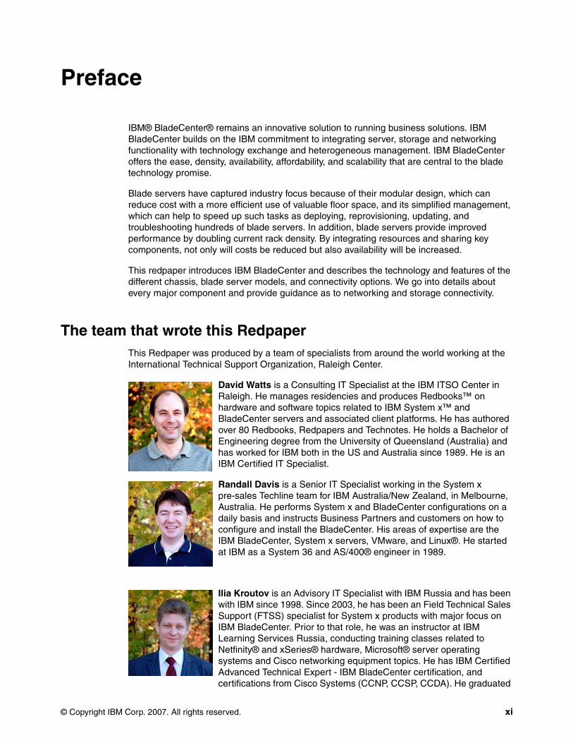
The team that wrote this RedpaperThis Redpaper was produced by a team of specialists from around the world working at the International Technical Support Organization, Raleigh Center.
David Watts is a Consulting IT Specialist at the IBM ITSO Center in Raleigh. He manages residencies and produces Redbooks™ on hardware and software topics related to IBM System x™ and BladeCenter servers and associated client platforms. He has authored over 80 Redbooks, Redpapers and Technotes. He holds a Bachelor of Engineering degree from the University of Queensland (Australia) and has worked for IBM both in the US and Australia since 1989. He is an IBM Certified IT Specialist.
Randall Davis is a Senior IT Specialist working in the System x pre-sales Techline team for IBM Australia/New Zealand, in Melbourne, Australia. He performs System x and BladeCenter configurations on a daily basis and instructs Business Partners and customers on how to configure and install the BladeCenter. His areas of expertise are the IBM BladeCenter, System x servers, VMware, and Linux®. He started at IBM as a System 36 and AS/400® engineer in 1989.
Ilia Kroutov is an Advisory IT Specialist with IBM Russia and has been with IBM since 1998. Since 2003, he has been an Field Technical Sales Support (FTSS) specialist for System x products with major focus on IBM BladeCenter. Prior to that role, he was an instructor at IBM Learning Services Russia, conducting training classes related to Netfinity® and xSeries® hardware, Microsoft® server operating systems and Cisco networking equipment topics. He has IBM Certified Advanced Technical Expert - IBM BladeCenter certification, and certifications from Cisco Systems (CCNP, CCSP, CCDA). He graduated

xii IBM BladeCenter Products and Technology
from the Moscow Engineering and Physics Institute and holds a Masters Degree in Computer Engineering. He is an Accredited IT Specialist.
Mollie Tucker is an undergraduate student at North Carolina State University. She is currently working toward a Bachelors of Science degree in Mechanical Engineering. As an Intern IT Specialist for IBM International Technical Support Organization in Raleigh, North Carolina, she specializes in IBM BladeCenter.
Thanks to the authors of the first edition of the Solution Assurance Product Review Guide upon which this redpaper is based:
� Rufus Credle� Yoko Fujiwara� Marc Muehlhoff
Thanks to the following people for their contributions to this project:
ITSO:
� Tamikia Barrow� Byron Braswell� Carolyn Briscoe� Rufus Credle� Margaret Ticknor
BladeCenter and System x Marketing:
� Mark Chapman� John Fitzgerald� Hal Humrickhouse� Ishan Sehgal� Scott Tease
BladeCenter Development:
� Sharon Alonzo� Khalid Ansari� Matthew Eckl� Nathan Flowers� Parker Grannis� Robert Jakes� Bret Lehman� Douglas Pase� Jonri Rothwell� Victor Stankevich� Doug Vassello� Mark Welch
IBM employees from around the world:
� Massimo Re Ferre', IBM Systems Group Technical Sales, Italy� Olaf Menke, IBM Pre-Sales Support
Become a published authorJoin us for a two- to six-week residency program! Help write an IBM Redbook dealing with specific products or solutions, while getting hands-on experience with leading-edge

Preface xiii
technologies. You'll have the opportunity to team with IBM technical professionals, Business Partners, and Clients.
Your efforts will help increase product acceptance and customer satisfaction. As a bonus, you'll develop a network of contacts in IBM development labs, and increase your productivity and marketability.
Find out more about the residency program, browse the residency index, and apply online at:
ibm.com/redbooks/residencies.html
Comments welcomeYour comments are important to us!
We want our papers to be as helpful as possible. Send us your comments about this Redpaper or other Redbooks in one of the following ways:
� Use the online Contact us review redbook form found at:
ibm.com/redbooks
� Send your comments in an email to:
� Mail your comments to:
IBM Corporation, International Technical Support OrganizationDept. HYTD Mail Station P0992455 South RoadPoughkeepsie, NY 12601-5400

xiv IBM BladeCenter Products and Technology
© Copyright IBM Corp. 2007. All rights reserved. 1
Chapter 1. Product overview
Blade servers are thin servers that insert into a single rack-mounted chassis which supplies shared power, cooling, and networking infrastructure. Each server is an independent server with its own processors, memory, storage, network controllers, operating system, and applications. Blade servers came to market around 2000, initially to meet clients’ needs for greater ease of administration and increased server density in the data center environment.
When IBM released the IBM BladeCenter in November 2002, it quickly changed the industry with its modular design. The IBM BladeCenter provides complete redundancy in a chassis, and enables network and storage integration.
In this chapter, we cover the following topics:
� 1.1, “Support matrixes” on page 2
� 1.2, “BladeCenter chassis” on page 4
� 1.3, “Blade servers” on page 18
1
2 IBM BladeCenter Products and Technology
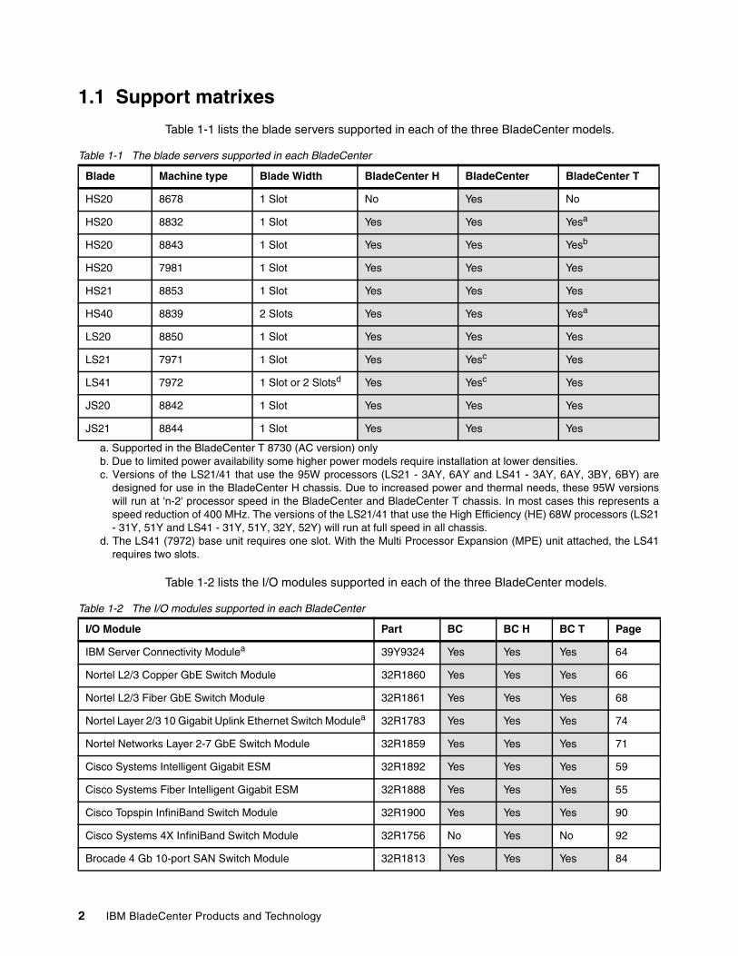
1.1 Support matrixes
Table 1-1 lists the blade servers supported in each of the three BladeCenter models.
Table 1-1 The blade servers supported in each BladeCenter
Table 1-2 lists the I/O modules supported in each of the three BladeCenter models.
Table 1-2 The I/O modules supported in each BladeCenter
Blade Machine type Blade Width BladeCenter H BladeCenter BladeCenter T
HS20 8678 1 Slot No Yes No
HS20 8832 1 Slot Yes Yes Yesa
a. Supported in the BladeCenter T 8730 (AC version) only
HS20 8843 1 Slot Yes Yes Yesb
b. Due to limited power availability some higher power models require installation at lower densities.
HS20 7981 1 Slot Yes Yes Yes
HS21 8853 1 Slot Yes Yes Yes
HS40 8839 2 Slots Yes Yes Yesa
LS20 8850 1 Slot Yes Yes Yes
LS21 7971 1 Slot Yes Yesc
c. Versions of the LS21/41 that use the 95W processors (LS21 - 3AY, 6AY and LS41 - 3AY, 6AY, 3BY, 6BY) aredesigned for use in the BladeCenter H chassis. Due to increased power and thermal needs, these 95W versionswill run at 'n-2' processor speed in the BladeCenter and BladeCenter T chassis. In most cases this represents aspeed reduction of 400 MHz. The versions of the LS21/41 that use the High Efficiency (HE) 68W processors (LS21- 31Y, 51Y and LS41 - 31Y, 51Y, 32Y, 52Y) will run at full speed in all chassis.
Yes
LS41 7972 1 Slot or 2 Slotsd
d. The LS41 (7972) base unit requires one slot. With the Multi Processor Expansion (MPE) unit attached, the LS41requires two slots.
Yes Yesc Yes
JS20 8842 1 Slot Yes Yes Yes
JS21 8844 1 Slot Yes Yes Yes
I/O Module Part BC BC H BC T Page
IBM Server Connectivity Modulea 39Y9324 Yes Yes Yes 64
Nortel L2/3 Copper GbE Switch Module 32R1860 Yes Yes Yes 66
Nortel L2/3 Fiber GbE Switch Module 32R1861 Yes Yes Yes 68
Nortel Layer 2/3 10 Gigabit Uplink Ethernet Switch Modulea 32R1783 Yes Yes Yes 74
Nortel Networks Layer 2-7 GbE Switch Module 32R1859 Yes Yes Yes 71
Cisco Systems Intelligent Gigabit ESM 32R1892 Yes Yes Yes 59
Cisco Systems Fiber Intelligent Gigabit ESM 32R1888 Yes Yes Yes 55
Cisco Topspin InfiniBand Switch Module 32R1900 Yes Yes Yes 90
Cisco Systems 4X InfiniBand Switch Module 32R1756 No Yes No 92
Brocade 4 Gb 10-port SAN Switch Module 32R1813 Yes Yes Yes 84
Chapter 1. Product overview 3
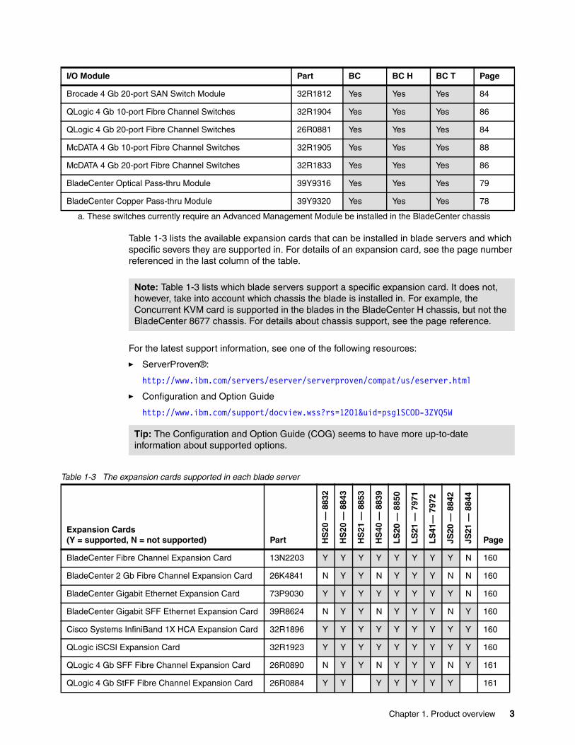
Table 1-3 lists the available expansion cards that can be installed in blade servers and which specific severs they are supported in. For details of an expansion card, see the page number referenced in the last column of the table.
For the latest support information, see one of the following resources:
� ServerProven®:
http://www.ibm.com/servers/eserver/serverproven/compat/us/eserver.html
� Configuration and Option Guide
http://www.ibm.com/support/docview.wss?rs=1201&uid=psg1SCOD-3ZVQ5W
Table 1-3 The expansion cards supported in each blade server
Brocade 4 Gb 20-port SAN Switch Module 32R1812 Yes Yes Yes 84
QLogic 4 Gb 10-port Fibre Channel Switches 32R1904 Yes Yes Yes 86
QLogic 4 Gb 20-port Fibre Channel Switches 26R0881 Yes Yes Yes 84
McDATA 4 Gb 10-port Fibre Channel Switches 32R1905 Yes Yes Yes 88
McDATA 4 Gb 20-port Fibre Channel Switches 32R1833 Yes Yes Yes 86
BladeCenter Optical Pass-thru Module 39Y9316 Yes Yes Yes 79
BladeCenter Copper Pass-thru Module 39Y9320 Yes Yes Yes 78
a. These switches currently require an Advanced Management Module be installed in the BladeCenter chassis
I/O Module Part BC BC H BC T Page
Note: Table 1-3 lists which blade servers support a specific expansion card. It does not, however, take into account which chassis the blade is installed in. For example, the Concurrent KVM card is supported in the blades in the BladeCenter H chassis, but not the BladeCenter 8677 chassis. For details about chassis support, see the page reference.
Tip: The Configuration and Option Guide (COG) seems to have more up-to-date information about supported options.
Expansion Cards(Y = supported, N = not supported) Part H
S20
— 8
832
HS
20 —
884
3
HS
21 —
885
3
HS
40 —
883
9
LS
20 —
885
0
LS
21 —
797
1
LS
41—
797
2
JS20
— 8
842
JS21
— 8
844
Page
BladeCenter Fibre Channel Expansion Card 13N2203 Y Y Y Y Y Y Y Y N 160
BladeCenter 2 Gb Fibre Channel Expansion Card 26K4841 N Y Y N Y Y Y N N 160
BladeCenter Gigabit Ethernet Expansion Card 73P9030 Y Y Y Y Y Y Y Y N 160
BladeCenter Gigabit SFF Ethernet Expansion Card 39R8624 N Y Y N Y Y Y N Y 160
Cisco Systems InfiniBand 1X HCA Expansion Card 32R1896 Y Y Y Y Y Y Y Y Y 160
QLogic iSCSI Expansion Card 32R1923 Y Y Y Y Y Y Y Y Y 160
QLogic 4 Gb SFF Fibre Channel Expansion Card 26R0890 N Y Y N Y Y Y N Y 161
QLogic 4 Gb StFF Fibre Channel Expansion Card 26R0884 Y Y Y Y Y Y Y 161
4 IBM BladeCenter Products and Technology
1.2 BladeCenter chassis
There are three chassis in the BladeCenter family:
� IBM BladeCenter provides the greatest density and common fabric support and is the lowest entry cost option.
� IBM BladeCenter H delivers high performance, extreme reliability, and ultimate flexibility for the most demanding IT environments.
� IBM BladeCenter T models are designed specifically for telecommunications network infrastructures and other rugged environments.
All three chassis share a common set of blades and switch modules.
1.2.1 IBM BladeCenter
IBM designed the IBM BladeCenter (machine type 8677) to be a highly modular chassis to accommodate a range of diverse business requirements. BladeCenter supports not only blade servers, but also a wide range of networking modules, including Gigabit Ethernet, Fibre Channel, and InfiniBand for high-speed connectivity to the client’s existing network environment. BladeCenter also supports a redundant pair of Management Modules for comprehensive systems management.
Providing a wide selection of integrated switching options, BladeCenter systems help you lower the Total Cost of Ownership (TCO) by eliminating the need to purchase additional keyboards, videos, and mice (KVM), Ethernet and Fibre Channel switches, or the cumbersome and expensive cabling the switches require. BladeCenter is a leader in the industry in providing flexibility and a variety of integration choices with components that fit into your infrastructure and deliver a comprehensive blade solution.
BladeCenter’s superior density and feature set are made possible by the BladeCenter innovative chassis architecture. Because BladeCenter uses super energy-efficient components and shared infrastructure architecture, clients can realize lower power consumption when compared to their most likely alternative, non-blade server designs. BladeCenter’s lower power consumption and Calibrated Vectored Cooling™ allow more servers to fit in a tight power or cooling environment.
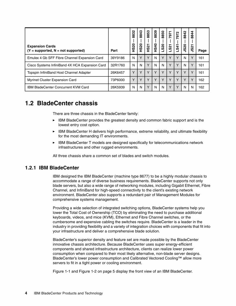
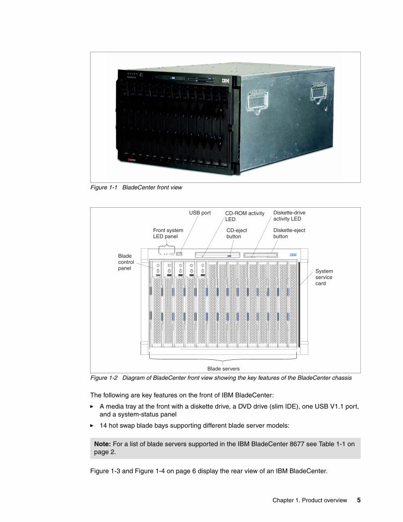
Figure 1-1 and Figure 1-2 on page 5 display the front view of an IBM BladeCenter.
Emulex 4 Gb SFF Fibre Channel Expansion Card 39Y9186 N Y Y N Y Y Y N Y 161
Cisco Systems InfiniBand 4X HCA Expansion Card 32R1760 N N Y N N Y Y N Y 161
Topspin InfiniBand Host Channel Adapter 26K6457 Y Y Y Y Y Y Y Y Y 161
Myrinet Cluster Expansion Card 73P6000 Y Y Y Y Y Y Y Y Y 162
IBM BladeCenter Concurrent KVM Card 26K5939 N N Y N N Y Y N N 162
Expansion Cards(Y = supported, N = not supported) Part H
S20
— 8
832
HS
20 —
884
3
HS
21 —
885
3
HS
40 —
883
9
LS
20 —
885
0
LS
21 —
797
1
LS
41—
797
2
JS20
— 8
842
JS21
— 8
844
Page
Chapter 1. Product overview 5
Figure 1-1 BladeCenter front view
Figure 1-2 Diagram of BladeCenter front view showing the key features of the BladeCenter chassis
The following are key features on the front of IBM BladeCenter:
� A media tray at the front with a diskette drive, a DVD drive (slim IDE), one USB V1.1 port, and a system-status panel
� 14 hot swap blade bays supporting different blade server models:
Figure 1-3 and Figure 1-4 on page 6 display the rear view of an IBM BladeCenter.
Note: For a list of blade servers supported in the IBM BladeCenter 8677 see Table 1-1 on page 2.
Front systemLED panel
CD-ejectbutton
Diskette-ejectbutton
Diskette-driveactivity LED
Blade servers
Bladecontrolpanel
USB port CD-ROM activityLED
Systemservicecard
6 IBM BladeCenter Products and Technology
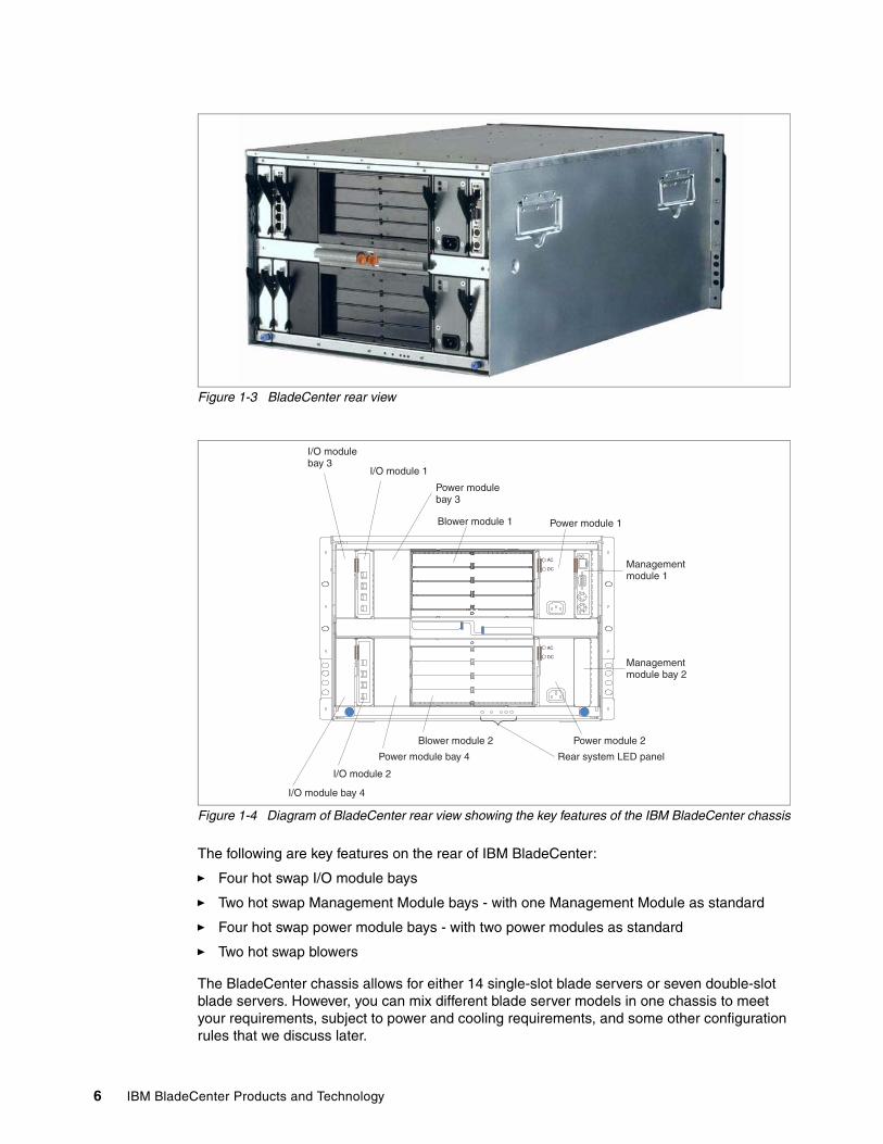
Figure 1-3 BladeCenter rear view
Figure 1-4 Diagram of BladeCenter rear view showing the key features of the IBM BladeCenter chassis
The following are key features on the rear of IBM BladeCenter:
� Four hot swap I/O module bays
� Two hot swap Management Module bays - with one Management Module as standard
� Four hot swap power module bays - with two power modules as standard
� Two hot swap blowers
The BladeCenter chassis allows for either 14 single-slot blade servers or seven double-slot blade servers. However, you can mix different blade server models in one chassis to meet your requirements, subject to power and cooling requirements, and some other configuration rules that we discuss later.
AC
AC
DC
DC
I/O modulebay 3
I/O module 1
I/O module bay 4
I/O module 2
Power modulebay 3
Power module 1
Power module bay 4
Power module 2
Managementmodule 1
Managementmodule bay 2
Blower module 1
Blower module 2
Rear system LED panel
Chapter 1. Product overview 7
The current model BladeCenter chassis (8677-3Rx) ships standard with one Advanced Management Module. This module provides the ability to manage the chassis and well as providing the local KVM function. An optional redundant advanced Management Module provides IBM BladeCenter with higher levels of resiliency. While in the chassis, the second module is in passive or standby mode. If the active or primary module fails, the second module is automatically enabled with all of the configuration settings of the primary module. This function provides clients with easy remote management and connectivity to the BladeCenter chassis for their critical applications.
Further details regarding the features and functions of the management modules can be found in 2.1, “Management modules” on page 32.
The BladeCenter does not ship standard with any I/O modules. You need to choose these I/O modules depending on your connectivity needs. An Ethernet Switch Module (ESM) will be required in I/O module bays 1 and 2, to enable the use of both Ethernet ports on a Blade Server. The I/O modules required in I/O module bays 3 and 4 will depend on the I/O Expansion Card installed in the Blade Servers.
We discuss guidelines about how to install I/O module options in detail in Chapter 2, “BladeCenter chassis and infrastructure configuration” on page 31.
The BladeCenter chassis ships standard with:
� One advanced management module� Two hot swap power supply modules� Two hot swap blower modules� one USB v1.1 port� One DVD-ROM drive� One 1.44 MB diskette drive
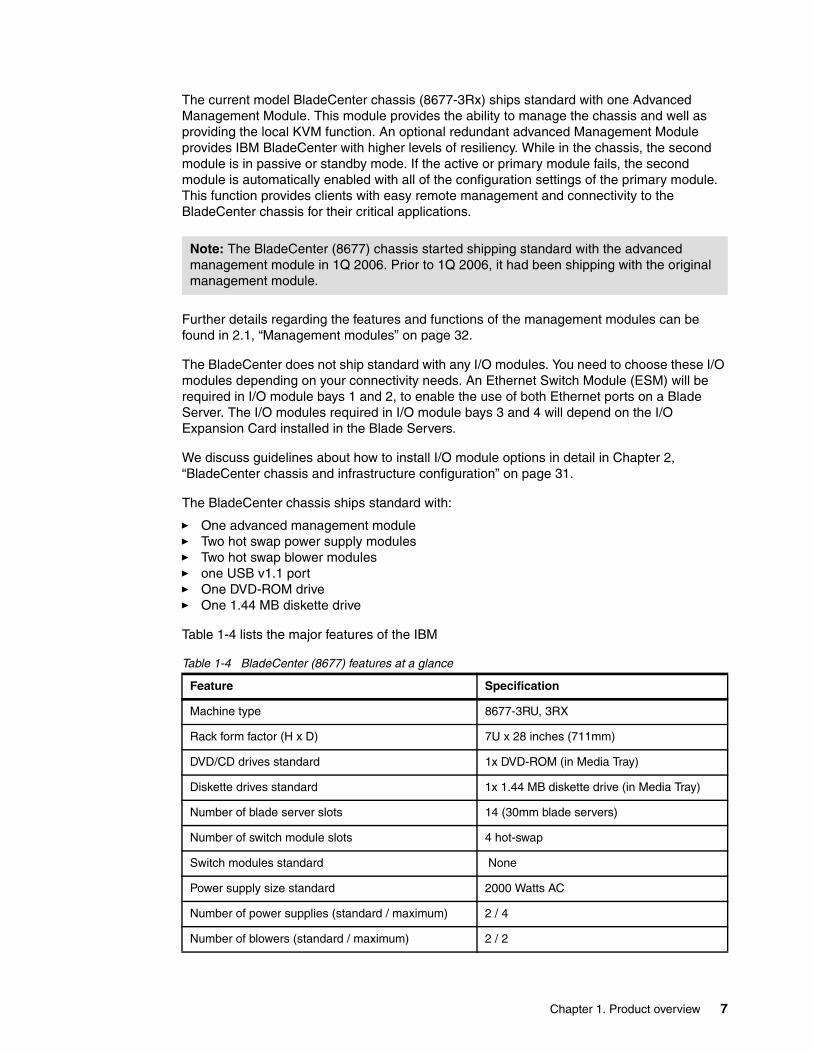
Table 1-4 lists the major features of the IBM
Table 1-4 BladeCenter (8677) features at a glance
Note: The BladeCenter (8677) chassis started shipping standard with the advanced management module in 1Q 2006. Prior to 1Q 2006, it had been shipping with the original management module.
Feature Specification
Machine type 8677-3RU, 3RX
Rack form factor (H x D) 7U x 28 inches (711mm)
DVD/CD drives standard 1x DVD-ROM (in Media Tray)
Diskette drives standard 1x 1.44 MB diskette drive (in Media Tray)
Number of blade server slots 14 (30mm blade servers)
Number of switch module slots 4 hot-swap
Switch modules standard None
Power supply size standard 2000 Watts AC
Number of power supplies (standard / maximum) 2 / 4
Number of blowers (standard / maximum) 2 / 2
8 IBM BladeCenter Products and Technology
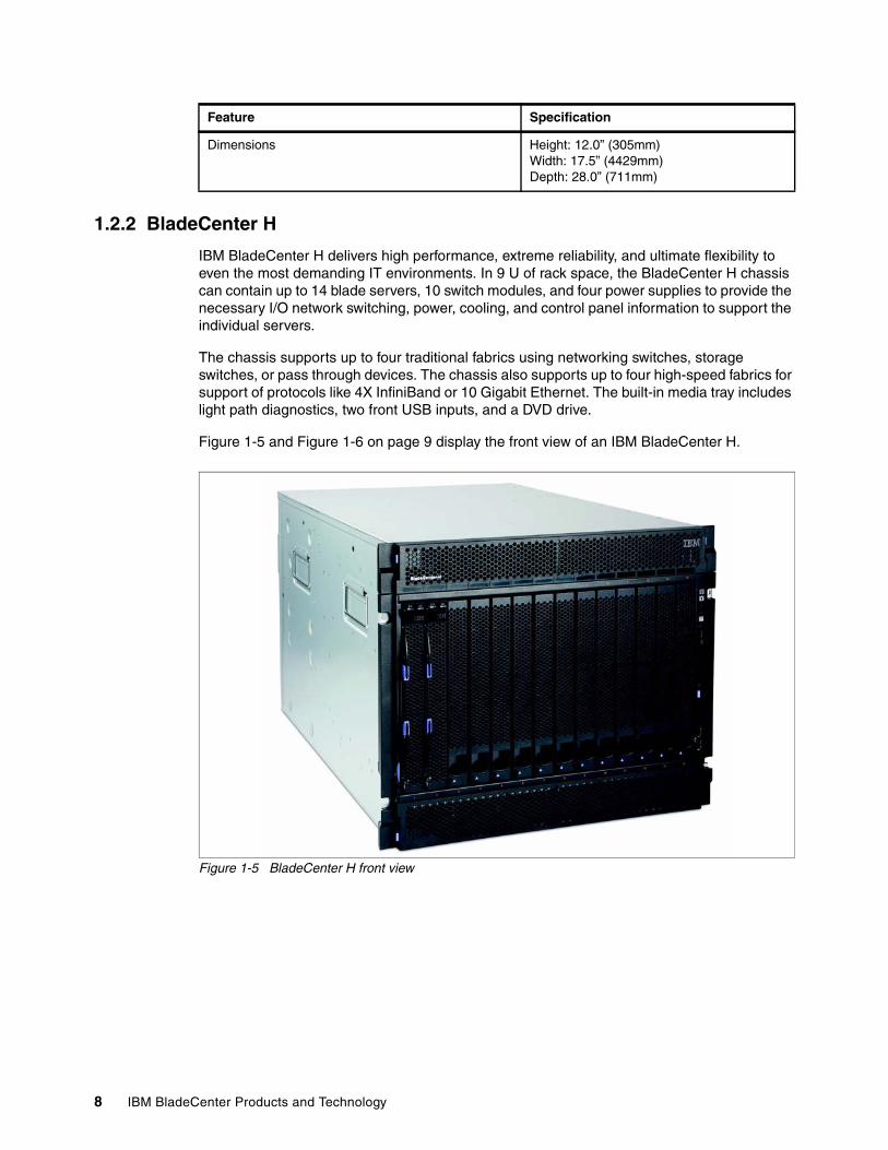
1.2.2 BladeCenter H
IBM BladeCenter H delivers high performance, extreme reliability, and ultimate flexibility to even the most demanding IT environments. In 9 U of rack space, the BladeCenter H chassis can contain up to 14 blade servers, 10 switch modules, and four power supplies to provide the necessary I/O network switching, power, cooling, and control panel information to support the individual servers.
The chassis supports up to four traditional fabrics using networking switches, storage switches, or pass through devices. The chassis also supports up to four high-speed fabrics for support of protocols like 4X InfiniBand or 10 Gigabit Ethernet. The built-in media tray includes light path diagnostics, two front USB inputs, and a DVD drive.
Figure 1-5 and Figure 1-6 on page 9 display the front view of an IBM BladeCenter H.
Figure 1-5 BladeCenter H front view
Dimensions Height: 12.0” (305mm) Width: 17.5” (4429mm) Depth: 28.0” (711mm)
Feature Specification
Chapter 1. Product overview 9
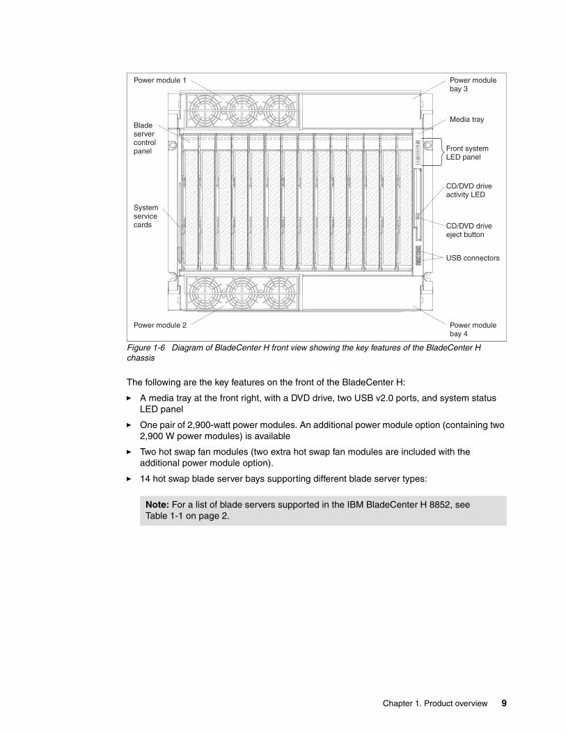
Figure 1-6 Diagram of BladeCenter H front view showing the key features of the BladeCenter H chassis
The following are the key features on the front of the BladeCenter H:
� A media tray at the front right, with a DVD drive, two USB v2.0 ports, and system status LED panel
� One pair of 2,900-watt power modules. An additional power module option (containing two 2,900 W power modules) is available
� Two hot swap fan modules (two extra hot swap fan modules are included with the additional power module option).
� 14 hot swap blade server bays supporting different blade server types:
Note: For a list of blade servers supported in the IBM BladeCenter H 8852, see Table 1-1 on page 2.
Front systemLED panel
CD/DVD driveeject button
Bladeservercontrolpanel
USB connectors
CD/DVD driveactivity LED
Systemservicecards
Power module 1 Power modulebay 3
Media tray
Power module 2 Power modulebay 4
10 IBM BladeCenter Products and Technology
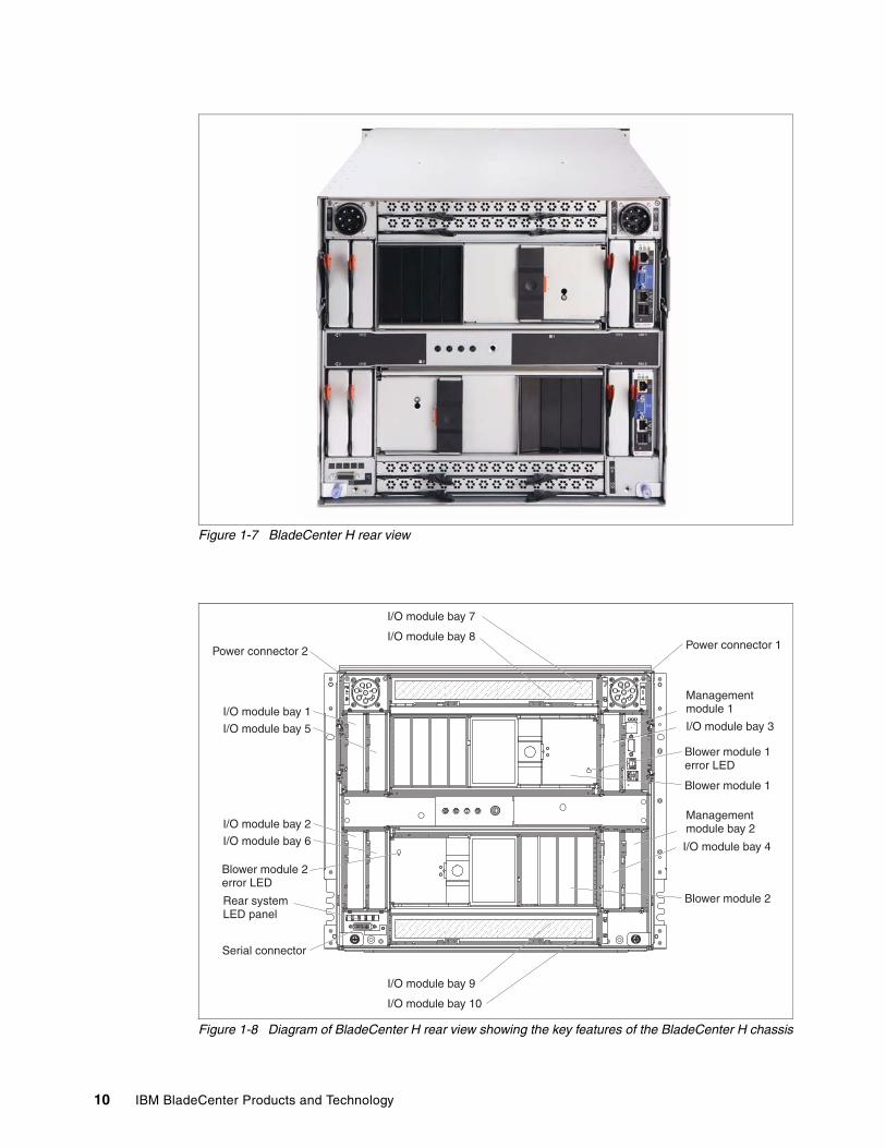
Figure 1-7 BladeCenter H rear view
Figure 1-8 Diagram of BladeCenter H rear view showing the key features of the BladeCenter H chassis
I/O module bay 4
I/O module bay 3
I/O module bay 2
I/O module bay 6
I/O module bay 1
I/O module bay 7
I/O module bay 9
I/O module bay 8
I/O module bay 10
I/O module bay 5
Power connector 2 Power connector 1
Managementmodule 1
Managementmodule bay 2
Blower module 1
Blower module 1error LED
Blower module 2error LED
Blower module 2Rear systemLED panel
Serial connector

Chapter 1. Product overview 11
The following are the key features on the rear of the BladeCenter H:
� Two hot-swap blower modules as standard
� Two hot swap management-module bays - with one management-module as standard
� Four traditional fabric switch modules
� Four high speed fabric switch modules
� Serial port breakout connector to give direct serial connection to installed blades (for those blades with the functionality)
The BladeCenter H chassis allows for either 14 single-slot blade servers or seven double-slot blade servers. However, you can mix different blade server models in one chassis to meet your requirements.
The BladeCenter H chassis ships standard with one Advanced Management Module. This module provides the ability to manage the chassis and well as providing the local KVM function. The optional redundant Advanced Management Module provides the IBM BladeCenter H with higher levels of resiliency. While in the chassis, the second module is in passive or standby mode. If the active or primary module fails, the second module is automatically enabled with all of the configuration settings of the primary module. This function provides clients with easy remote management and connectivity to the BladeCenter H chassis for their critical applications.
The BladeCenter H does not ship standard with any I/O modules. You choose these I/O modules based on your connectivity needs. An Ethernet Switch Module (ESM) will be required in I/O module bays 1 and 2, to enable the use of both Ethernet ports on a Blade Server. The I/O modules required in I/O module bays 3 and 4 will depend on the I/O Expansion Card installed in the blade servers. The I/O modules required in the high speed I/O module bays 7, 8, 9 and 10 will depend on the I/O Host Channel Adapter cards installed in the Blade Servers.
Guidelines about how to install I/O module options are discussed in detail in Chapter 2, “BladeCenter chassis and infrastructure configuration” on page 31.
The BladeCenter H chassis requires 200 to 240 V AC power. The BladeCenter H chassis comes standard with no power cord. Power cords need to be ordered separately.
The BladeCenter H chassis ships standard with:
� One advanced management module� Two blower modules� Two power supply modules (one pair of 2,900-watt power modules).� Two hot swap power supply fan modules.� Two USB v2.0 ports� One DVD-ROM drive.
The chassis does not have a diskette drive. An optional USB-attached 1.44 MB diskette drive is available.
Table 1-5 BladeCenter H features at a glance
Feature Specifications
Machine type 8852-4XU
Rack form factor (H x D) 9U x 28 inches (711mm)
DVD/CD drives standard 1x DVD-ROM (in Media Tray)
12 IBM BladeCenter Products and Technology
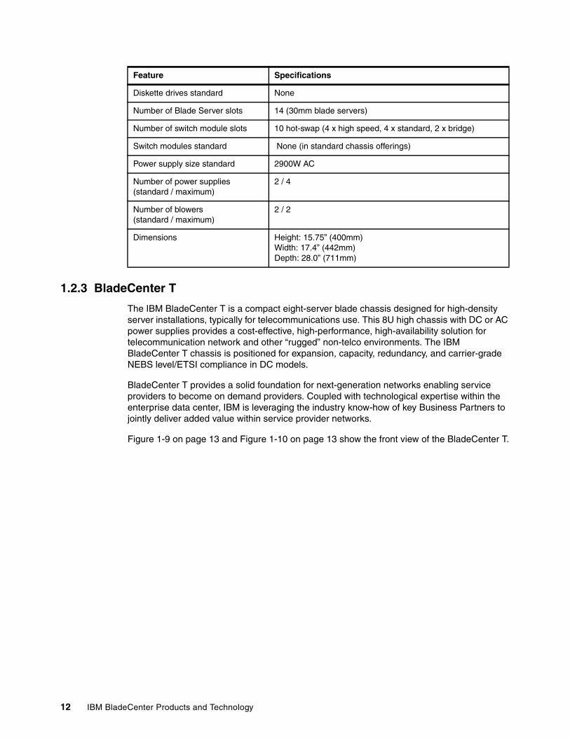
1.2.3 BladeCenter T
The IBM BladeCenter T is a compact eight-server blade chassis designed for high-density server installations, typically for telecommunications use. This 8U high chassis with DC or AC power supplies provides a cost-effective, high-performance, high-availability solution for telecommunication network and other “rugged” non-telco environments. The IBM BladeCenter T chassis is positioned for expansion, capacity, redundancy, and carrier-grade NEBS level/ETSI compliance in DC models.
BladeCenter T provides a solid foundation for next-generation networks enabling service providers to become on demand providers. Coupled with technological expertise within the enterprise data center, IBM is leveraging the industry know-how of key Business Partners to jointly deliver added value within service provider networks.
Figure 1-9 on page 13 and Figure 1-10 on page 13 show the front view of the BladeCenter T.
Diskette drives standard None
Number of Blade Server slots 14 (30mm blade servers)
Number of switch module slots 10 hot-swap (4 x high speed, 4 x standard, 2 x bridge)
Switch modules standard None (in standard chassis offerings)
Power supply size standard 2900W AC
Number of power supplies (standard / maximum)
2 / 4
Number of blowers(standard / maximum)
2 / 2
Dimensions Height: 15.75” (400mm) Width: 17.4” (442mm) Depth: 28.0” (711mm)
Feature Specifications
Chapter 1. Product overview 13
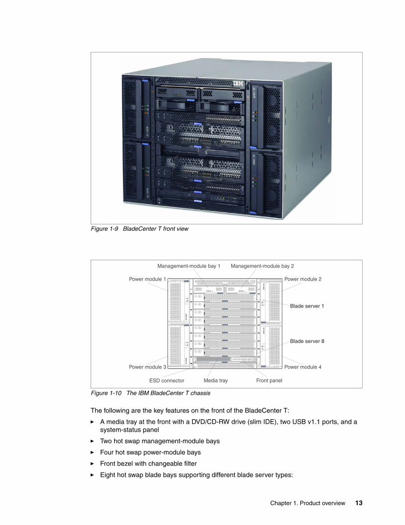
Figure 1-9 BladeCenter T front view
Figure 1-10 The IBM BladeCenter T chassis
The following are the key features on the front of the BladeCenter T:
� A media tray at the front with a DVD/CD-RW drive (slim IDE), two USB v1.1 ports, and a system-status panel
� Two hot swap management-module bays
� Four hot swap power-module bays
� Front bezel with changeable filter
� Eight hot swap blade bays supporting different blade server types:
Management-module bay 1
Power module 3
Power module 1
Power module 4
Power module 2
Front panelMedia trayESD connector
Management-module bay 2
CMM1
CMM2
Blade server 1
Blade server 8
14 IBM BladeCenter Products and Technology
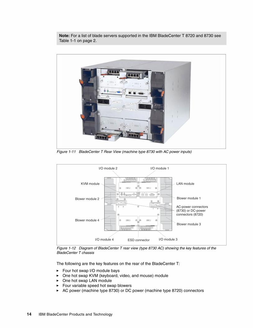
Figure 1-11 BladeCenter T Rear View (machine type 8730 with AC power inputs)
Figure 1-12 Diagram of BladeCenter T rear view (type 8730 AC) showing the key features of the BladeCenter T chassis
The following are the key features on the rear of the BladeCenter T:
� Four hot swap I/O module bays� One hot swap KVM (keyboard, video, and mouse) module� One hot swap LAN module� Four variable speed hot swap blowers� AC power (machine type 8730) or DC power (machine type 8720) connectors
Note: For a list of blade servers supported in the IBM BladeCenter T 8720 and 8730 see Table 1-1 on page 2.
I/O module 2 I/O module 1
I/O module 4 ESD connector I/O module 3
LAN moduleKVM module
Blower module 2
Blower module 4
Blower module 1
Blower module 3
TOP D TOP D
BTM E BTM E
2 41 3
CRTMJR
MNR
2Alarms
1
AC-power connectors(8730) or DC-powerconnectors (8720)
Chapter 1. Product overview 15
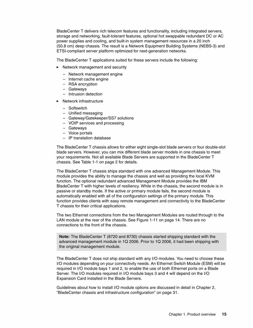
BladeCenter T delivers rich telecom features and functionality, including integrated servers, storage and networking, fault-tolerant features, optional hot swappable redundant DC or AC power supplies and cooling, and built-in system management resources in a 20 inch (50.8 cm) deep chassis. The result is a Network Equipment Building Systems (NEBS-3) and ETSI-compliant server platform optimized for next-generation networks.
The BladeCenter T applications suited for these servers include the following:
� Network management and security
– Network management engine– Internet cache engine– RSA encryption– Gateways– Intrusion detection
� Network infrastructure
– Softswitch– Unified messaging– Gateway/Gatekeeper/SS7 solutions– VOIP services and processing– Gateways– Voice portals– IP translation database
The BladeCenter T chassis allows for either eight single-slot blade servers or four double-slot blade servers. However, you can mix different blade server models in one chassis to meet your requirements. Not all available Blade Servers are supported in the BladeCenter T chassis. See Table 1-1 on page 2 for details.
The BladeCenter T chassis ships standard with one advanced Management Module. This module provides the ability to manage the chassis and well as providing the local KVM function. The optional redundant advanced Management Module provides the IBM BladeCenter T with higher levels of resiliency. While in the chassis, the second module is in passive or standby mode. If the active or primary module fails, the second module is automatically enabled with all of the configuration settings of the primary module. This function provides clients with easy remote management and connectivity to the BladeCenter T chassis for their critical applications.
The two Ethernet connections from the two Management Modules are routed through to the LAN module at the rear of the chassis. See Figure 1-11 on page 14. There are no connections to the front of the chassis.
The BladeCenter T does not ship standard with any I/O modules. You need to choose these I/O modules depending on your connectivity needs. An Ethernet Switch Module (ESM) will be required in I/O module bays 1 and 2, to enable the use of both Ethernet ports on a Blade Server. The I/O modules required in I/O module bays 3 and 4 will depend on the I/O Expansion Card installed in the Blade Servers.
Guidelines about how to install I/O module options are discussed in detail in Chapter 2, “BladeCenter chassis and infrastructure configuration” on page 31.
Note: The BladeCenter T (8720 and 8730) chassis started shipping standard with the advanced management module in 1Q 2006. Prior to 1Q 2006, it had been shipping with the original management module.
16 IBM BladeCenter Products and Technology
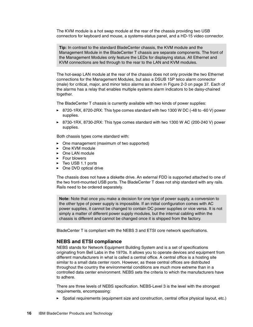
The KVM module is a hot swap module at the rear of the chassis providing two USB connectors for keyboard and mouse, a systems-status panel, and a HD-15 video connector.
The hot-swap LAN module at the rear of the chassis does not only provide the two Ethernet connections for the Management Modules, but also a DSUB 15P telco alarm connector (male) for critical, major, and minor telco alarms as shown in Figure 2-3 on page 37. Each of the alarms has a relay that enables multiple systems alarm indicators to be daisy-chained together.
The BladeCenter T chassis is currently available with two kinds of power supplies:
� 8720-1RX, 8720-2RX: This type comes standard with two 1300 W DC (-48 to -60 V) power supplies.
� 8730-1RX, 8730-2RX: This type comes standard with two 1300 W AC (200-240 V) power supplies.
Both chassis types come standard with:
� One management (maximum of two supported)� One KVM module� One LAN module� Four blowers� Two USB 1.1 ports� One DVD optical drive
The chassis does not have a diskette drive. An external FDD is supported attached to one of the two front-mounted USB ports. The BladeCenter T does not ship standard with any rails. Rails need to be ordered separately.
BladeCenter T is compliant with the NEBS 3 and ETSI core network specifications.
NEBS and ETSI complianceNEBS stands for Network Equipment Building System and is a set of specifications originating from Bell Labs in the 1970s. It allows you to operate devices and equipment from different manufacturers in what is called a central office. A central office is a hosting site similar to a small data center room. However, as these central offices are distributed throughout the country the environmental conditions are much more extreme than in a controlled data center environment. NEBS sets the criteria to which the manufacturers have to adhere.
There are three levels of NEBS specification. NEBS-Level 3 is the level with the strongest requirements, encompassing:
� Spatial requirements (equipment size and construction, central office physical layout, etc.)
Tip: In contrast to the standard BladeCenter chassis, the KVM module and the Management Module in the BladeCenter T chassis are separate components. The front of the Management Modules only feature the LEDs for displaying status. All Ethernet and KVM connections are fed through to the rear to the LAN and KVM modules.
Note: Note that once you make a decision for one type of power supply, a conversion to the other type of power supply is impossible. If an initial configuration comes with AC power supplies, it cannot be changed to contain DC power supplies or vice versa. It is not simply a matter of different power supply modules, but the internal cabling within the chassis is different and cannot be changed once it is shipped from the factory.
Chapter 1. Product overview 17
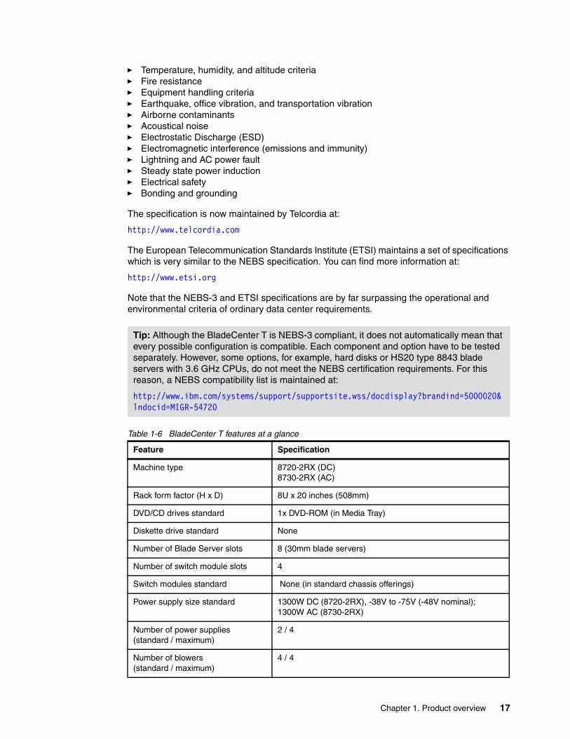
� Temperature, humidity, and altitude criteria� Fire resistance� Equipment handling criteria� Earthquake, office vibration, and transportation vibration� Airborne contaminants� Acoustical noise� Electrostatic Discharge (ESD)� Electromagnetic interference (emissions and immunity)� Lightning and AC power fault� Steady state power induction� Electrical safety� Bonding and grounding
The specification is now maintained by Telcordia at:
http://www.telcordia.com
The European Telecommunication Standards Institute (ETSI) maintains a set of specifications which is very similar to the NEBS specification. You can find more information at:
http://www.etsi.org
Note that the NEBS-3 and ETSI specifications are by far surpassing the operational and environmental criteria of ordinary data center requirements.
Table 1-6 BladeCenter T features at a glance
Tip: Although the BladeCenter T is NEBS-3 compliant, it does not automatically mean that every possible configuration is compatible. Each component and option have to be tested separately. However, some options, for example, hard disks or HS20 type 8843 blade servers with 3.6 GHz CPUs, do not meet the NEBS certification requirements. For this reason, a NEBS compatibility list is maintained at:
http://www.ibm.com/systems/support/supportsite.wss/docdisplay?brandind=5000020&lndocid=MIGR-54720
Feature Specification
Machine type 8720-2RX (DC)8730-2RX (AC)
Rack form factor (H x D) 8U x 20 inches (508mm)
DVD/CD drives standard 1x DVD-ROM (in Media Tray)
Diskette drive standard None
Number of Blade Server slots 8 (30mm blade servers)
Number of switch module slots 4
Switch modules standard None (in standard chassis offerings)
Power supply size standard 1300W DC (8720-2RX), -38V to -75V (-48V nominal);1300W AC (8730-2RX)
Number of power supplies (standard / maximum)
2 / 4
Number of blowers(standard / maximum)
4 / 4
18 IBM BladeCenter Products and Technology
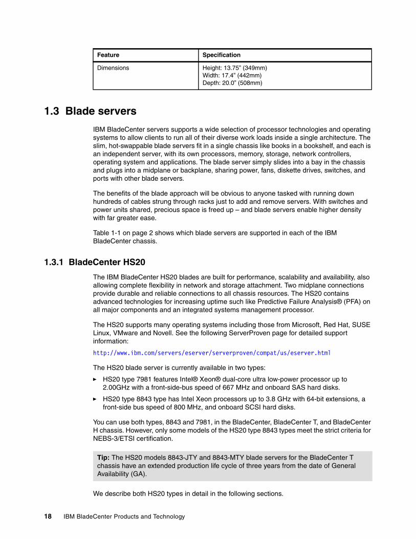
1.3 Blade servers
IBM BladeCenter servers supports a wide selection of processor technologies and operating systems to allow clients to run all of their diverse work loads inside a single architecture. The slim, hot-swappable blade servers fit in a single chassis like books in a bookshelf, and each is an independent server, with its own processors, memory, storage, network controllers, operating system and applications. The blade server simply slides into a bay in the chassis and plugs into a midplane or backplane, sharing power, fans, diskette drives, switches, and ports with other blade servers.
The benefits of the blade approach will be obvious to anyone tasked with running down hundreds of cables strung through racks just to add and remove servers. With switches and power units shared, precious space is freed up – and blade servers enable higher density with far greater ease.
Table 1-1 on page 2 shows which blade servers are supported in each of the IBM BladeCenter chassis.
1.3.1 BladeCenter HS20
The IBM BladeCenter HS20 blades are built for performance, scalability and availability, also allowing complete flexibility in network and storage attachment. Two midplane connections provide durable and reliable connections to all chassis resources. The HS20 contains advanced technologies for increasing uptime such like Predictive Failure Analysis® (PFA) on all major components and an integrated systems management processor.
The HS20 supports many operating systems including those from Microsoft, Red Hat, SUSE Linux, VMware and Novell. See the following ServerProven page for detailed support information:
http://www.ibm.com/servers/eserver/serverproven/compat/us/eserver.html
The HS20 blade server is currently available in two types:
� HS20 type 7981 features Intel® Xeon® dual-core ultra low-power processor up to 2.00GHz with a front-side-bus speed of 667 MHz and onboard SAS hard disks.
� HS20 type 8843 type has Intel Xeon processors up to 3.8 GHz with 64-bit extensions, a front-side bus speed of 800 MHz, and onboard SCSI hard disks.
You can use both types, 8843 and 7981, in the BladeCenter, BladeCenter T, and BladeCenter H chassis. However, only some models of the HS20 type 8843 types meet the strict criteria for NEBS-3/ETSI certification.
We describe both HS20 types in detail in the following sections.
Dimensions Height: 13.75” (349mm)Width: 17.4” (442mm) Depth: 20.0” (508mm)
Feature Specification
Tip: The HS20 models 8843-JTY and 8843-MTY blade servers for the BladeCenter T chassis have an extended production life cycle of three years from the date of General Availability (GA).
Chapter 1. Product overview 19
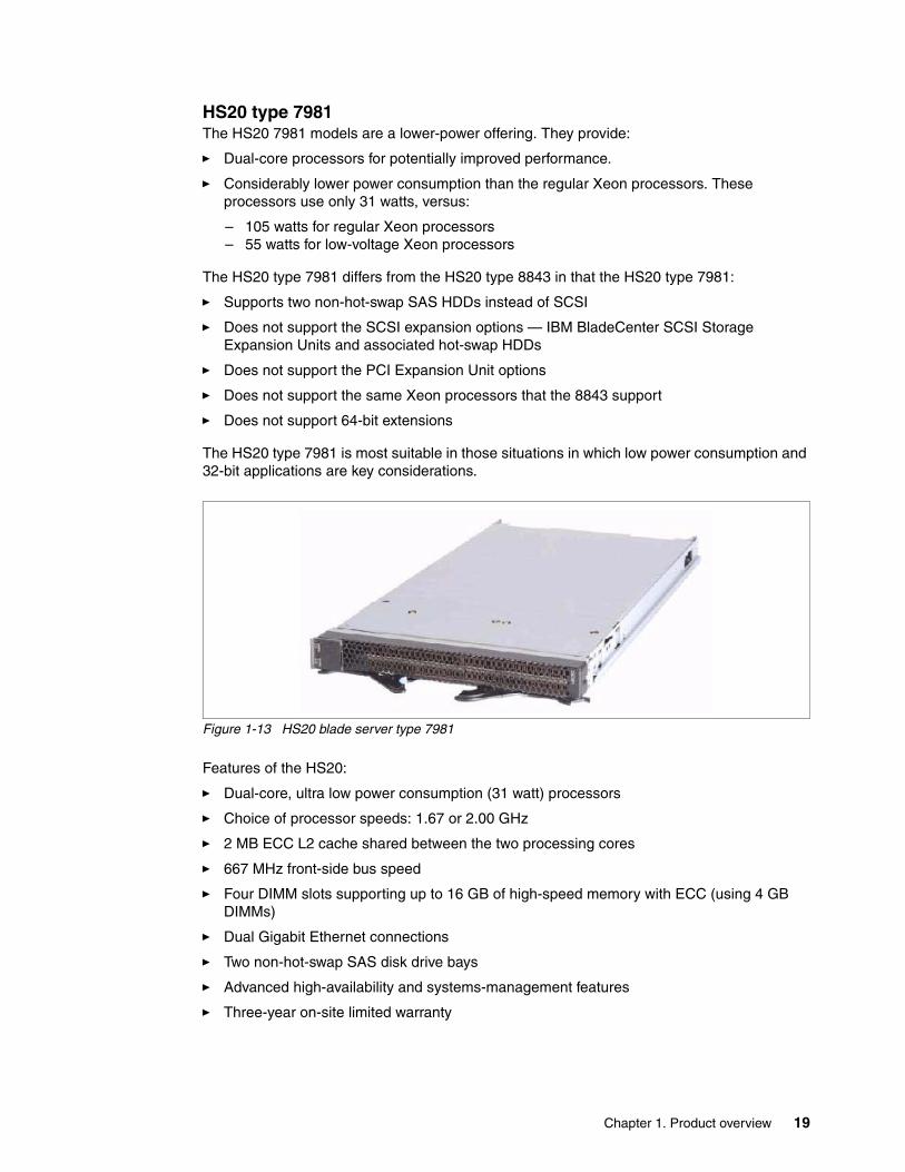
HS20 type 7981The HS20 7981 models are a lower-power offering. They provide:
� Dual-core processors for potentially improved performance.
� Considerably lower power consumption than the regular Xeon processors. These processors use only 31 watts, versus:
– 105 watts for regular Xeon processors– 55 watts for low-voltage Xeon processors
The HS20 type 7981 differs from the HS20 type 8843 in that the HS20 type 7981:
� Supports two non-hot-swap SAS HDDs instead of SCSI
� Does not support the SCSI expansion options — IBM BladeCenter SCSI Storage Expansion Units and associated hot-swap HDDs
� Does not support the PCI Expansion Unit options
� Does not support the same Xeon processors that the 8843 support
� Does not support 64-bit extensions
The HS20 type 7981 is most suitable in those situations in which low power consumption and 32-bit applications are key considerations.
Figure 1-13 HS20 blade server type 7981
Features of the HS20:
� Dual-core, ultra low power consumption (31 watt) processors
� Choice of processor speeds: 1.67 or 2.00 GHz
� 2 MB ECC L2 cache shared between the two processing cores
� 667 MHz front-side bus speed
� Four DIMM slots supporting up to 16 GB of high-speed memory with ECC (using 4 GB DIMMs)
� Dual Gigabit Ethernet connections
� Two non-hot-swap SAS disk drive bays
� Advanced high-availability and systems-management features
� Three-year on-site limited warranty
20 IBM BladeCenter Products and Technology
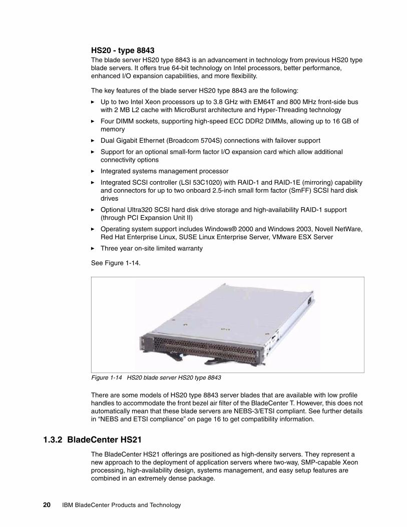
HS20 - type 8843The blade server HS20 type 8843 is an advancement in technology from previous HS20 type blade servers. It offers true 64-bit technology on Intel processors, better performance, enhanced I/O expansion capabilities, and more flexibility.
The key features of the blade server HS20 type 8843 are the following:
� Up to two Intel Xeon processors up to 3.8 GHz with EM64T and 800 MHz front-side bus with 2 MB L2 cache with MicroBurst architecture and Hyper-Threading technology
� Four DIMM sockets, supporting high-speed ECC DDR2 DIMMs, allowing up to 16 GB of memory
� Dual Gigabit Ethernet (Broadcom 5704S) connections with failover support
� Support for an optional small-form factor I/O expansion card which allow additional connectivity options
� Integrated systems management processor
� Integrated SCSI controller (LSI 53C1020) with RAID-1 and RAID-1E (mirroring) capability and connectors for up to two onboard 2.5-inch small form factor (SmFF) SCSI hard disk drives
� Optional Ultra320 SCSI hard disk drive storage and high-availability RAID-1 support (through PCI Expansion Unit II)
� Operating system support includes Windows® 2000 and Windows 2003, Novell NetWare, Red Hat Enterprise Linux, SUSE Linux Enterprise Server, VMware ESX Server
� Three year on-site limited warranty
See Figure 1-14.
Figure 1-14 HS20 blade server HS20 type 8843
There are some models of HS20 type 8843 server blades that are available with low profile handles to accommodate the front bezel air filter of the BladeCenter T. However, this does not automatically mean that these blade servers are NEBS-3/ETSI compliant. See further details in “NEBS and ETSI compliance” on page 16 to get compatibility information.
1.3.2 BladeCenter HS21
The BladeCenter HS21 offerings are positioned as high-density servers. They represent a new approach to the deployment of application servers where two-way, SMP-capable Xeon processing, high-availability design, systems management, and easy setup features are combined in an extremely dense package.
Chapter 1. Product overview 21
The HS21 blades require less space and power resources, when compared to an equivalent standard 1U server, because of their high-density design, reduced power requirements and single environment systems management.
The supported operating systems include those from Microsoft, Red Hat, SUSE Linux, VMware and Novell. See the following ServerProven page for further supported operating system information:
http://www.ibm.com/servers/eserver/serverproven/compat/us/eserver.html
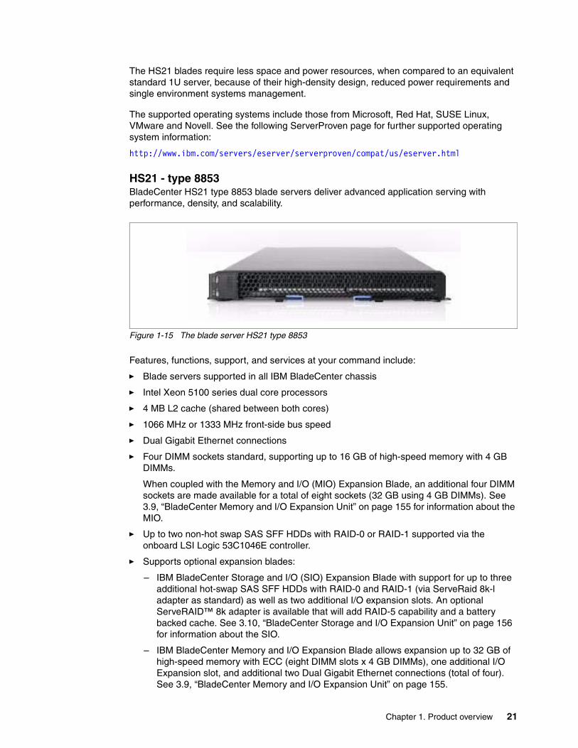
HS21 - type 8853BladeCenter HS21 type 8853 blade servers deliver advanced application serving with performance, density, and scalability.
Figure 1-15 The blade server HS21 type 8853
Features, functions, support, and services at your command include:
� Blade servers supported in all IBM BladeCenter chassis
� Intel Xeon 5100 series dual core processors
� 4 MB L2 cache (shared between both cores)
� 1066 MHz or 1333 MHz front-side bus speed
� Dual Gigabit Ethernet connections
� Four DIMM sockets standard, supporting up to 16 GB of high-speed memory with 4 GB DIMMs.
When coupled with the Memory and I/O (MIO) Expansion Blade, an additional four DIMM sockets are made available for a total of eight sockets (32 GB using 4 GB DIMMs). See 3.9, “BladeCenter Memory and I/O Expansion Unit” on page 155 for information about the MIO.
� Up to two non-hot swap SAS SFF HDDs with RAID-0 or RAID-1 supported via the onboard LSI Logic 53C1046E controller.
� Supports optional expansion blades:
– IBM BladeCenter Storage and I/O (SIO) Expansion Blade with support for up to three additional hot-swap SAS SFF HDDs with RAID-0 and RAID-1 (via ServeRaid 8k-l adapter as standard) as well as two additional I/O expansion slots. An optional ServeRAID™ 8k adapter is available that will add RAID-5 capability and a battery backed cache. See 3.10, “BladeCenter Storage and I/O Expansion Unit” on page 156 for information about the SIO.
– IBM BladeCenter Memory and I/O Expansion Blade allows expansion up to 32 GB of high-speed memory with ECC (eight DIMM slots x 4 GB DIMMs), one additional I/O Expansion slot, and additional two Dual Gigabit Ethernet connections (total of four). See 3.9, “BladeCenter Memory and I/O Expansion Unit” on page 155.
22 IBM BladeCenter Products and Technology
� Advanced high-availability and systems-management features
� Concurrent keyboard, video, mouse (KVM) support with addition of the optional IBM BladeCenter Concurrent KVM feature card. See 3.12.12, “Concurrent KVM Feature Card (cKVM)” on page 162.
� Three-year, on-site limited warranty
The supported operating systems are Microsoft Windows Server® 2003 32-bit and 64-bit, RHEL 3/4 32-bit and 64-bit, SLES 9 32-bit and 64-bit, Novell NetWare 6.5, Sun™ Solaris™ 10, VMware ESX Server 3.0. See the following ServerProven page for further supported NOS information:
http://www.ibm.com/servers/eserver/serverproven/compat/us/eserver.html
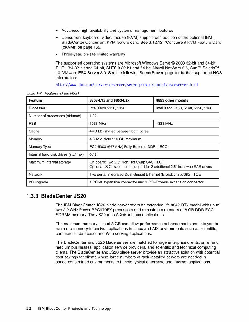
Table 1-7 Features of the HS21
1.3.3 BladeCenter JS20
The IBM BladeCenter JS20 blade server offers an extended life 8842-RTx model with up to two 2.2 GHz Power PPC970FX processors and a maximum memory of 8 GB DDR ECC SDRAM memory. The JS20 runs AIX® or Linux applications.
The maximum memory size of 8 GB can allow performance enhancements and lets you to run more memory-intensive applications in Linux and AIX environments such as scientific, commercial, database, and Web serving applications.
The BladeCenter and JS20 blade server are matched to large enterprise clients, small and medium businesses, application service providers, and scientific and technical computing clients. The BladeCenter and JS20 blade server provide an attractive solution with potential cost savings for clients where large numbers of rack-installed servers are needed in space-constrained environments to handle typical enterprise and Internet applications.
Feature 8853-L1x and 8853-L2x 8853 other models
Processor Intel Xeon 5110, 5120 Intel Xeon 5130, 5140, 5150, 5160
Number of processors (std/max) 1 / 2
FSB 1033 MHz 1333 MHz
Cache 4MB L2 (shared between both cores)
Memory 4 DIMM slots / 16 GB maximum
Memory Type PC2-5300 (667MHz) Fully Buffered DDR II ECC
Internal hard disk drives (std/max) 0 / 2
Maximum internal storage On board: Two 2.5” Non Hot Swap SAS HDDOptional: SIO blade offers support for 3 additional 2.5” hot-swap SAS drives
Network Two ports, Integrated Dual Gigabit Ethernet (Broadcom 5708S), TOE
I/O upgrade 1 PCI-X expansion connector and 1 PCI-Express expansion connector
Chapter 1. Product overview 23
Examples of ideal environments are:
� Compute-intensive, transaction processing� Server consolidation� Internet or intranet serving� Web commerce serving� E-mail applications� Applications serving� File and print serving� Application serving
BladeCenter packaging makes POWER™ technology more affordable.
The JS20 8842-RTx model is designed with a power management capability to give you the maximum uptime possible for your systems. In short term extended thermal conditions, the 8842-RTx automatically reduces the frequency of the processor to maintain acceptable thermal levels.
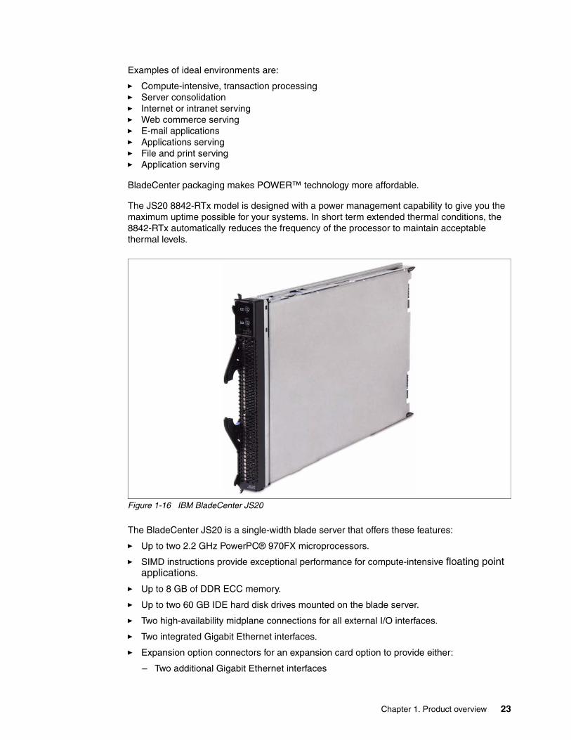
Figure 1-16 IBM BladeCenter JS20
The BladeCenter JS20 is a single-width blade server that offers these features:
� Up to two 2.2 GHz PowerPC® 970FX microprocessors.
� SIMD instructions provide exceptional performance for compute-intensive floating point applications.
� Up to 8 GB of DDR ECC memory.
� Up to two 60 GB IDE hard disk drives mounted on the blade server.
� Two high-availability midplane connections for all external I/O interfaces.
� Two integrated Gigabit Ethernet interfaces.
� Expansion option connectors for an expansion card option to provide either:
– Two additional Gigabit Ethernet interfaces
24 IBM BladeCenter Products and Technology
– Two 2 Gbps Fibre Channel interfaces
– One Myrinet interface
� Blade Systems Management Processor.
� Predictive Failure Analysis (PFA).
� IBM Director and Cluster Systems Management (CSM).
� NEBS-3/ETSI compliant (RTx model in a BladeCenter T chassis only).
� Operating system support includes SUSE Linux Enterprise Server, Red Hat Enterprise Linux, and AIX 5L™ V5.2 and V5.3. See ServerProven for further supported NOS information:
http://www.ibm.com/servers/eserver/serverproven/compat/us/eserver.html
1.3.4 BladeCenter JS21
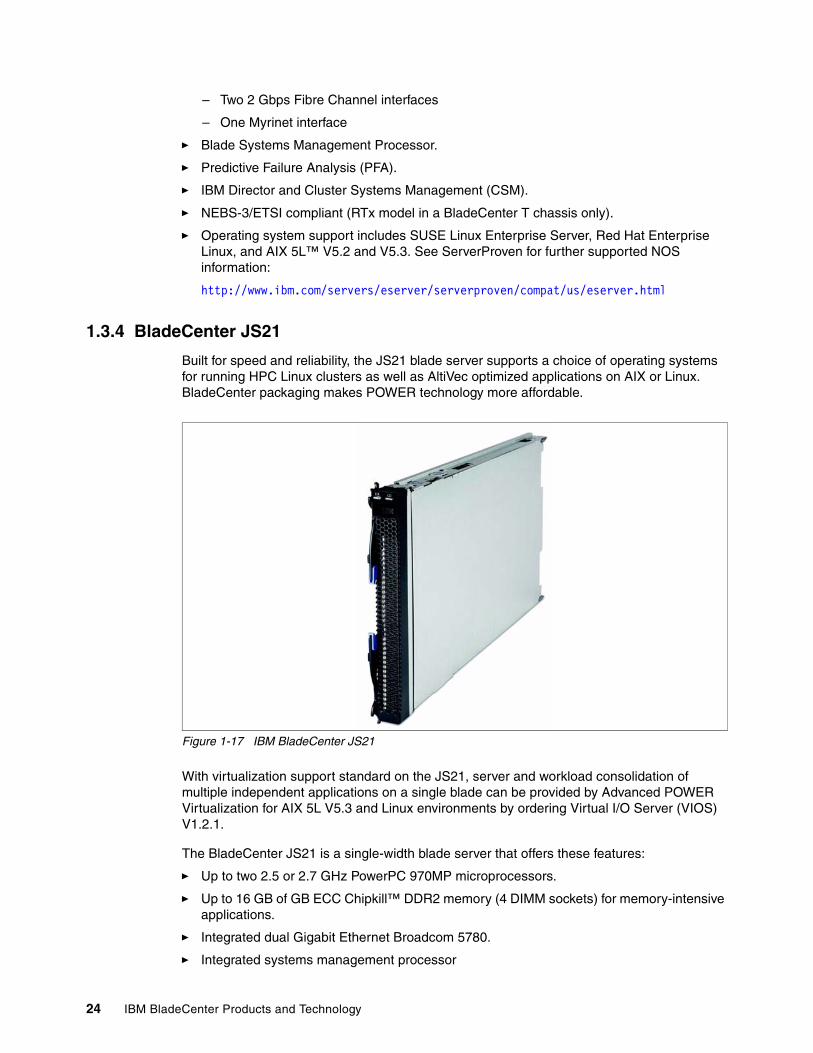
Built for speed and reliability, the JS21 blade server supports a choice of operating systems for running HPC Linux clusters as well as AltiVec optimized applications on AIX or Linux. BladeCenter packaging makes POWER technology more affordable.
Figure 1-17 IBM BladeCenter JS21
With virtualization support standard on the JS21, server and workload consolidation of multiple independent applications on a single blade can be provided by Advanced POWER Virtualization for AIX 5L V5.3 and Linux environments by ordering Virtual I/O Server (VIOS) V1.2.1.
The BladeCenter JS21 is a single-width blade server that offers these features:
� Up to two 2.5 or 2.7 GHz PowerPC 970MP microprocessors.
� Up to 16 GB of GB ECC Chipkill™ DDR2 memory (4 DIMM sockets) for memory-intensive applications.
� Integrated dual Gigabit Ethernet Broadcom 5780.
� Integrated systems management processor
Chapter 1. Product overview 25
� Integrated SAS controller with up RAID 0 or RAID 1 support
� Support for up to two 2.5 inch SAS hard disk drives
� Support for Broadcom 5780: PCI-Express and dual gigabit Ethernet; Fibre Channel, Myrinet, InfiniBand, and iSCSI TOE connections; AltiVec optimized application development; Advanced POWER Virtualization (enabled through Virtual I/O Server
� Operating system support includes SUSE Linux Enterprise Server 9 SP3, or later, Red Hat Enterprise Linux AS 4 U3, or later, for POWER, and AIX 5L V5.2 and V5.3.
See the following ServerProven page for further supported NOS information:
http://www.ibm.com/servers/eserver/serverproven/compat/us/eserver.html
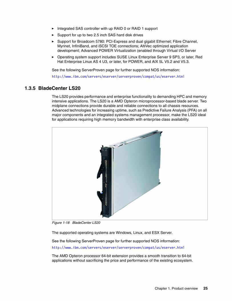
1.3.5 BladeCenter LS20
The LS20 provides performance and enterprise functionality to demanding HPC and memory intensive applications. The LS20 is a AMD Opteron microprocessor-based blade server. Two midplane connections provide durable and reliable connections to all chassis resources. Advanced technologies for increasing uptime, such as Predictive Failure Analysis (PFA) on all major components and an integrated systems management processor, make the LS20 ideal for applications requiring high memory bandwidth with enterprise class availability.
Figure 1-18 BladeCenter LS20
The supported operating systems are Windows, Linux, and ESX Server.
See the following ServerProven page for further supported NOS information:
http://www.ibm.com/servers/eserver/serverproven/compat/us/eserver.html
The AMD Opteron processor 64-bit extension provides a smooth transition to 64-bit applications without sacrificing the price and performance of the existing ecosystem.
26 IBM BladeCenter Products and Technology
The key features of the LS20 (See Figure 1-18 on page 25) are:
� Up to two AMD Opteron processors at 2.0, 2.2 and 2.4 GHz Dual Core or 2.0, 2.4, 2.6, and 2.8 Single Core with 1 MB L2 cache with AMD Direct Connect Architecture and 64-bit extension
� Up to four memory slots supporting PC3200 ECC DDR RDIMMs memory allowing for a maximum of 16 GB memory
� 1 GB or 2 GB of RAM is installed as standard with a maximum of 16 GB in 4 DIMM sockets total. Support DIMMs are High-speed PC3200 CL3 DDR VLP SDRAM RDIMMs supporting ECC and Chipkill.
� Dual Gigabit Ethernet (BroadcomR BCM5704S) connections with teaming and failover support
� Support for one optional I/O expansion card which allows additional connectivity options
� Integrated systems management processor using the IBM integrated system management processor (ISMP).
� Integrated SCSI RAID controller with SCSI RAID-1 capability and connectors for up to two onboard SCSI hard disk drives
� Extended blade production life cycle of three years from date of General Availability for certain models
� Three year on-site limited warranty
1.3.6 BladeCenter LS21
The LS21 for BladeCenter blade servers are high-throughput, two-socket, SMP-capable, AMD Opteron-based blade servers. This two-socket AMD Opteron blade server is well suited to HPC and other applications requiring high performance and high-speed fabrics.
The processors used in these blades are standard- and low-power, full-performance Opteron processors. The standard AMD Opteron processors draw a maximum of 95 W. Specially manufactured low-power processors operate at 68 W or less without any performance trade-offs. This savings in power at the processor level combined with the smarter power solution that BladeCenter delivers make these blades very attractive to clients who have limited power and cooling resources.
The BladeCenter LS21 is a single-width blade server that offers these features:
� Up to two high-performance, AMD Dual-Core Opteron processors
� System board containing eight DIMM connectors, supporting 512 MB, 1 GB, 2 GB, or 4 GB DIMMs. Up to 32 GB of system memory is supported with 4 GB DIMMs.
� SAS controller, supporting one internal SAS drive (36 or 73 GB) and up to three additional SAS drives with optional SIO blade.
� Two TCP/IP Offload Engine-enabled (TOE) Gigabit Ethernet controllers (Broadcom 5706S) standard, with load balancing and failover features
� Support for concurrent KVM (cKVM) and concurrent USB / DVD (cMedia) via Advanced Management Module and optional daughter card
� Support for Storage and I/O Expansion (SIO) Unit
� Three year on-site limited warranty
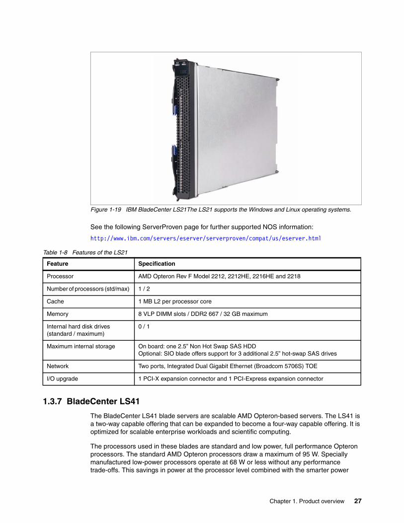
Chapter 1. Product overview 27
Figure 1-19 IBM BladeCenter LS21The LS21 supports the Windows and Linux operating systems.
See the following ServerProven page for further supported NOS information:
http://www.ibm.com/servers/eserver/serverproven/compat/us/eserver.html
Table 1-8 Features of the LS21
1.3.7 BladeCenter LS41
The BladeCenter LS41 blade servers are scalable AMD Opteron-based servers. The LS41 is a two-way capable offering that can be expanded to become a four-way capable offering. It is optimized for scalable enterprise workloads and scientific computing.
The processors used in these blades are standard and low power, full performance Opteron processors. The standard AMD Opteron processors draw a maximum of 95 W. Specially manufactured low-power processors operate at 68 W or less without any performance trade-offs. This savings in power at the processor level combined with the smarter power
Feature Specification
Processor AMD Opteron Rev F Model 2212, 2212HE, 2216HE and 2218
Number of processors (std/max) 1 / 2
Cache 1 MB L2 per processor core
Memory 8 VLP DIMM slots / DDR2 667 / 32 GB maximum
Internal hard disk drives (standard / maximum)
0 / 1
Maximum internal storage On board: one 2.5” Non Hot Swap SAS HDDOptional: SIO blade offers support for 3 additional 2.5” hot-swap SAS drives
Network Two ports, Integrated Dual Gigabit Ethernet (Broadcom 5706S) TOE
I/O upgrade 1 PCI-X expansion connector and 1 PCI-Express expansion connector
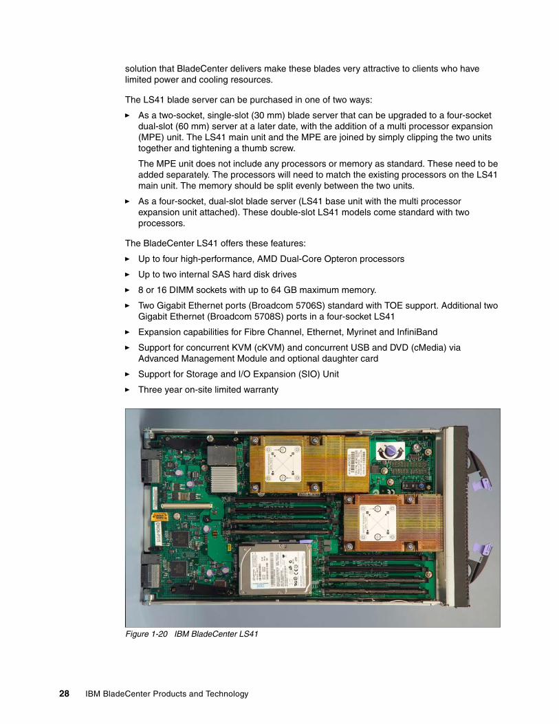
28 IBM BladeCenter Products and Technology
solution that BladeCenter delivers make these blades very attractive to clients who have limited power and cooling resources.
The LS41 blade server can be purchased in one of two ways:
� As a two-socket, single-slot (30 mm) blade server that can be upgraded to a four-socket dual-slot (60 mm) server at a later date, with the addition of a multi processor expansion (MPE) unit. The LS41 main unit and the MPE are joined by simply clipping the two units together and tightening a thumb screw.
The MPE unit does not include any processors or memory as standard. These need to be added separately. The processors will need to match the existing processors on the LS41 main unit. The memory should be split evenly between the two units.
� As a four-socket, dual-slot blade server (LS41 base unit with the multi processor expansion unit attached). These double-slot LS41 models come standard with two processors.
The BladeCenter LS41 offers these features:
� Up to four high-performance, AMD Dual-Core Opteron processors
� Up to two internal SAS hard disk drives
� 8 or 16 DIMM sockets with up to 64 GB maximum memory.
� Two Gigabit Ethernet ports (Broadcom 5706S) standard with TOE support. Additional two Gigabit Ethernet (Broadcom 5708S) ports in a four-socket LS41
� Expansion capabilities for Fibre Channel, Ethernet, Myrinet and InfiniBand
� Support for concurrent KVM (cKVM) and concurrent USB and DVD (cMedia) via Advanced Management Module and optional daughter card
� Support for Storage and I/O Expansion (SIO) Unit
� Three year on-site limited warranty
Figure 1-20 IBM BladeCenter LS41
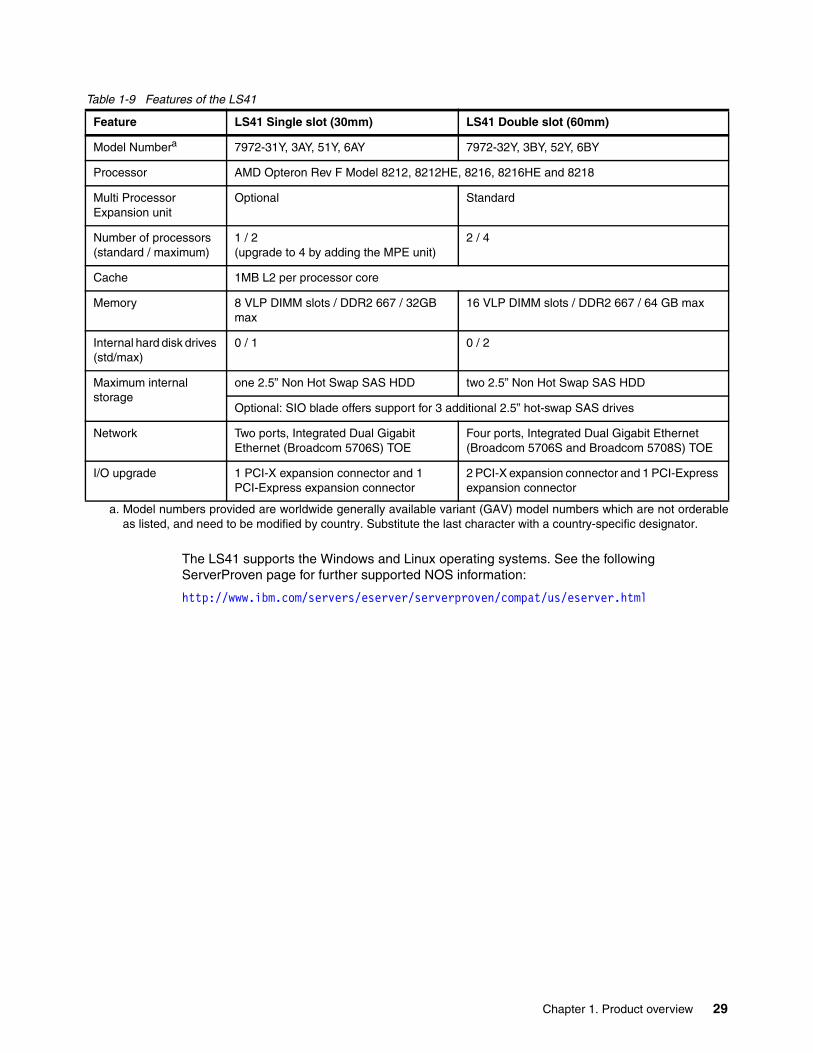
Chapter 1. Product overview 29
Table 1-9 Features of the LS41
The LS41 supports the Windows and Linux operating systems. See the following ServerProven page for further supported NOS information:
http://www.ibm.com/servers/eserver/serverproven/compat/us/eserver.html
Feature LS41 Single slot (30mm) LS41 Double slot (60mm)
Model Numbera
a. Model numbers provided are worldwide generally available variant (GAV) model numbers which are not orderableas listed, and need to be modified by country. Substitute the last character with a country-specific designator.
7972-31Y, 3AY, 51Y, 6AY 7972-32Y, 3BY, 52Y, 6BY
Processor AMD Opteron Rev F Model 8212, 8212HE, 8216, 8216HE and 8218
Multi Processor Expansion unit
Optional Standard
Number of processors (standard / maximum)
1 / 2(upgrade to 4 by adding the MPE unit)
2 / 4
Cache 1MB L2 per processor core
Memory 8 VLP DIMM slots / DDR2 667 / 32GB max
16 VLP DIMM slots / DDR2 667 / 64 GB max
Internal hard disk drives (std/max)
0 / 1 0 / 2
Maximum internal storage
one 2.5” Non Hot Swap SAS HDD two 2.5” Non Hot Swap SAS HDD
Optional: SIO blade offers support for 3 additional 2.5” hot-swap SAS drives
Network Two ports, Integrated Dual Gigabit Ethernet (Broadcom 5706S) TOE
Four ports, Integrated Dual Gigabit Ethernet (Broadcom 5706S and Broadcom 5708S) TOE
I/O upgrade 1 PCI-X expansion connector and 1 PCI-Express expansion connector
2 PCI-X expansion connector and 1 PCI-Express expansion connector

30 IBM BladeCenter Products and Technology
© Copyright IBM Corp. 2007. All rights reserved. 31
Chapter 2. BladeCenter chassis and infrastructure configuration
This chapter contains information about different infrastructure options available for IBM BladeCenter such as management, power, cooling, network and storage connectivity modules. The following topics will be covered:
� 2.1, “Management modules” on page 32� 2.2, “Blower modules” on page 38� 2.3, “Power modules” on page 41� 2.4, “Serial Port Breakout Cable” on page 47� 2.5, “I/O modules” on page 48� 2.6, “Ethernet switch modules” on page 53� 2.7, “Pass-thru modules” on page 77� 2.8, “Fibre Channel switch modules” on page 81� 2.9, “InfiniBand switch modules” on page 90� 2.10, “High speed switch modules” on page 92
For a general overview of the BladeCenter chassis, see “BladeCenter chassis” on page 4.
2
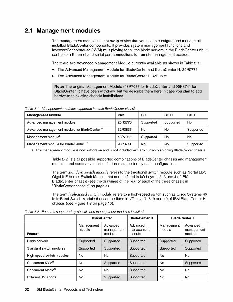
32 IBM BladeCenter Products and Technology
2.1 Management modules
The management module is a hot-swap device that you use to configure and manage all installed BladeCenter components. It provides system management functions and keyboard/video/mouse (KVM) multiplexing for all the blade servers in the BladeCenter unit. It controls an Ethernet and serial port connections for remote management access.
There are two Advanced Management Module currently available as shown in Table 2-1:
� The Advanced Management Module for BladeCenter and BladeCenter H, 25R5778
� The Advanced Management Module for BladeCenter T, 32R0835
Table 2-1 Management modules supported in each BladeCenter chassis
Table 2-2 lists all possible supported combinations of BladeCenter chassis and management modules and summarizes list of features supported by each configuration.
The term standard switch module refers to the traditional switch module such as Nortel L2/3 Gigabit Ethernet Switch Module that can be fitted in I/O bays 1, 2, 3 and 4 of IBM BladeCenter chassis (see the drawings of the rear of each of the three chassis in “BladeCenter chassis” on page 4).
The term high-speed switch module refers to a high-speed switch such as Cisco Systems 4X InfiniBand Switch Module that can be fitted in I/O bays 7, 8, 9 and 10 of IBM BladeCenter H chassis (see Figure 1-8 on page 10).
Table 2-2 Features supported by chassis and management modules installed
Note: The original Management Module (48P7055 for BladeCenter and 90P3741 for BladeCenter T) have been withdraw, but we describe them here in case you plan to add hardware to existing chassis installations.
Management module Part BC BC H BC T
Advanced management module 25R5778 Supported Supported No
Advanced management module for BladeCenter T 32R0835 No No Supported
Management modulea
a. This management module is now withdrawn and is not included with any currently shipping BladeCenter chassis
48P7055 Supported No No
Management module for BladeCenter Ta 90P3741 No No Supported
BladeCenter BladeCenter H BladeCenter T
Feature
Management module
Advanced management module
Advanced management module
Management module
Advanced management module
Blade servers Supported Supported Supported Supported Supported
Standard switch modules Supported Supported Supported Supported Supported
High-speed switch modules No No Supported No No
Concurrent KVMa No Supported Supported No Supported
Concurrent Mediaa No No Supported No No
External USB ports No Supported Supported No No
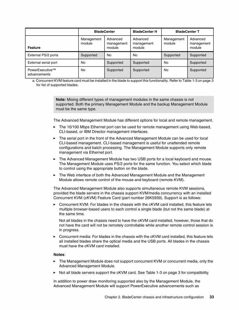
Chapter 2. BladeCenter chassis and infrastructure configuration 33
The Advanced Management Module has different options for local and remote management.
� The 10/100 Mbps Ethernet port can be used for remote management using Web-based, CLI-based, or IBM Director management interfaces.
� The serial port in the front of the Advanced Management Module can be used for local CLI-based management. CLI-based management is useful for unattended remote configurations and batch processing. The Management Module supports only remote management via Ethernet port.
� The Advanced Management Module has two USB ports for a local keyboard and mouse. The Management Module uses PS/2 ports for the same function. You select which blade to control using the appropriate button on the blade.
� The Web interface of both the Advanced Management Module and the Management Module allows remote control of the mouse and keyboard (remote KVM).
The Advanced Management Module also supports simultaneous remote KVM sessions, provided the blade servers in the chassis support KVM/media concurrency with an installed Concurrent KVM (cKVM) Feature Card (part number 26K5939). Support is as follows:
� Concurrent KVM: For blades in the chassis with the cKVM card installed, this feature lets multiple browser-based users to each control a single blade (but not the same blade) at the same time.
Not all blades in the chassis need to have the cKVM card installed, however, those that do not have the card will not be remotely controllable while another remote control session is in progress.
� Concurrent media: For blades in the chassis with the cKVM card installed, this feature lets all installed blades share the optical media and the USB ports. All blades in the chassis must have the cKVM card installed.
Notes:
� The Management Module does not support concurrent KVM or concurrent media, only the Advanced Management Module.
� Not all blade servers support the cKVM card. See Table 1-3 on page 3 for compatibility.
In addition to power draw monitoring supported also by the Management Module, the Advanced Management Module will support PowerExecutive advancements such as
External PS/2 ports Supported No No Supported Supported
External serial port No Supported Supported No Supported
PowerExecutive™ advancements
No Supported Supported No Supported
a. Concurrent KVM feature card must be installed in the blade to support this functionality. Refer to Table 1-3 on page 3for list of supported blades.
BladeCenter BladeCenter H BladeCenter T
Feature
Management module
Advanced management module
Advanced management module
Management module
Advanced management module
Note: Mixing different types of management modules in the same chassis is not supported. Both the primary Management Module and the backup Management Module must be the same type.
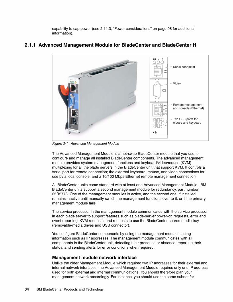
34 IBM BladeCenter Products and Technology
capability to cap power (see 2.11.3, “Power considerations” on page 98 for additional information).
2.1.1 Advanced Management Module for BladeCenter and BladeCenter H
Figure 2-1 Advanced Management Module
The Advanced Management Module is a hot-swap BladeCenter module that you use to configure and manage all installed BladeCenter components. The advanced management module provides system management functions and keyboard/video/mouse (KVM) multiplexing for all the blade servers in the BladeCenter unit that support KVM. It controls a serial port for remote connection; the external keyboard, mouse, and video connections for use by a local console; and a 10/100 Mbps Ethernet remote management connection.
All BladeCenter units come standard with at least one Advanced Management Module. IBM BladeCenter units support a second management module for redundancy, part number 25R5778. One of the management modules is active, and the second one, if installed, remains inactive until manually switch the management functions over to it, or if the primary management module fails.
The service processor in the management module communicates with the service processor in each blade server to support features such as blade-server power-on requests, error and event reporting, KVM requests, and requests to use the BladeCenter shared media tray (removable-media drives and USB connector).
You configure BladeCenter components by using the management module, setting information such as IP addresses. The management module communicates with all components in the BladeCenter unit, detecting their presence or absence, reporting their status, and sending alerts for error conditions when required.
Management module network interfaceUnlike the older Management Module which required two IP addresses for their external and internal network interfaces, the Advanced Management Module requires only one IP address used for both external and internal communications. You should therefore plan your management network accordingly. For instance, you should use the same subnet for
OK
TX/RX
LINK
Serial connector
Video
Remote managementand console (Ethernet)
Two USB ports formouse and keyboard
Chapter 2. BladeCenter chassis and infrastructure configuration 35
management module and I/O modules management interfaces. For more information see Chapter 4, “Network integration” on page 163
For more information, refer to the product publication IBM BladeCenter Advanced Management Module User's Guide and Management Module Command Line Interface Reference Guide.
Management module redundant configurationYou can configure one optional Advanced Management Module for higher availability by ordering part number 25R5778.
Table 2-3 Advanced Management Module for IBM BladeCenter and BladeCenter H
If you plan to use management module redundancy then we recommend to use another set of KVM cables for cabling redundant management modules. It that case when a management module failed then you need just select another console port without manual reconfiguration of KVM infrastructure.
The same rule applies to Ethernet cabling. We recommend you connect Ethernet ports on both management modules to the network to be able to manage remotely in case of failover without any reconfiguration.
For more information about Advanced Management Module, refer to the following product documentation:
� IBM BladeCenter Advanced Management Module for BladeCenter and BladeCenter H Installation Guide
� IBM BladeCenter Advanced Management Module User's Guide
� Advanced Management Module Command Line Interface Reference Guide
For more information about hardware management features, refer to the IBM Redbook IBM eServer xSeries and BladeCenter Server Management, SG24-6495.
Note: We recommend to use static IP addresses (or at least reservations for DHCP) for the Advanced Management Module to avoid some management issues.
Part Number Description
25R5778 IBM BladeCenter Advanced Management Module
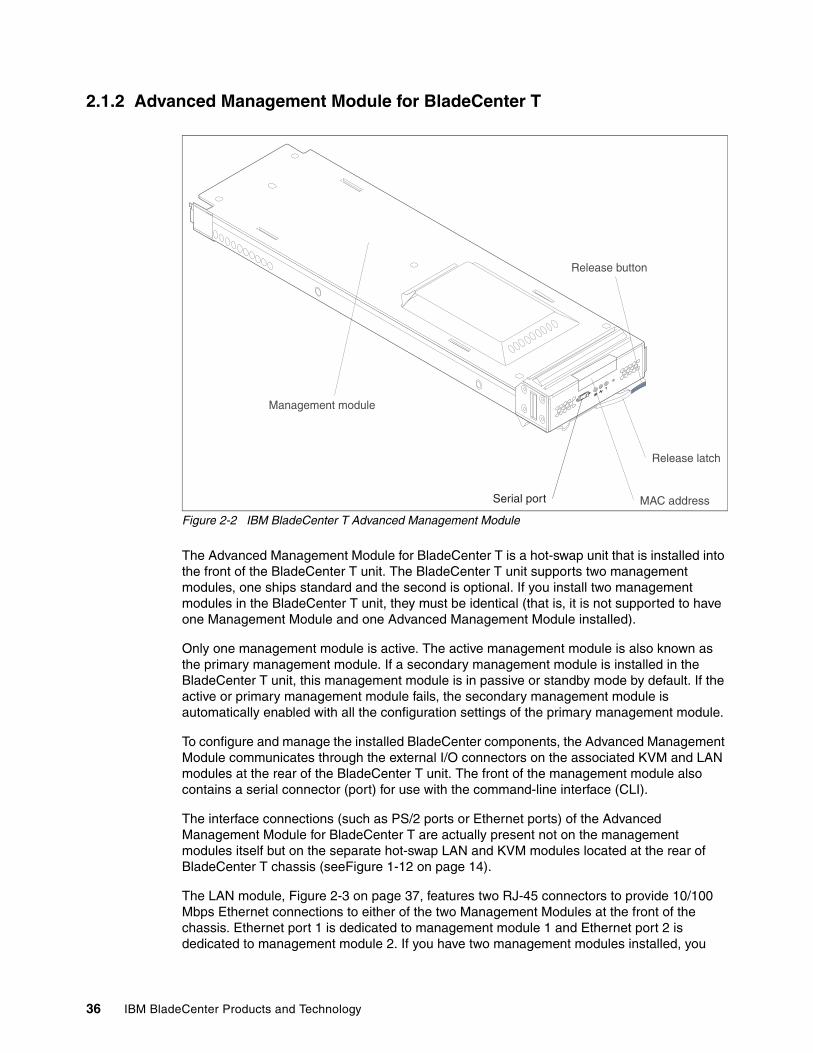
36 IBM BladeCenter Products and Technology
2.1.2 Advanced Management Module for BladeCenter T
Figure 2-2 IBM BladeCenter T Advanced Management Module
The Advanced Management Module for BladeCenter T is a hot-swap unit that is installed into the front of the BladeCenter T unit. The BladeCenter T unit supports two management modules, one ships standard and the second is optional. If you install two management modules in the BladeCenter T unit, they must be identical (that is, it is not supported to have one Management Module and one Advanced Management Module installed).
Only one management module is active. The active management module is also known as the primary management module. If a secondary management module is installed in the BladeCenter T unit, this management module is in passive or standby mode by default. If the active or primary management module fails, the secondary management module is automatically enabled with all the configuration settings of the primary management module.
To configure and manage the installed BladeCenter components, the Advanced Management Module communicates through the external I/O connectors on the associated KVM and LAN modules at the rear of the BladeCenter T unit. The front of the management module also contains a serial connector (port) for use with the command-line interface (CLI).
The interface connections (such as PS/2 ports or Ethernet ports) of the Advanced Management Module for BladeCenter T are actually present not on the management modules itself but on the separate hot-swap LAN and KVM modules located at the rear of BladeCenter T chassis (seeFigure 1-12 on page 14).
The LAN module, Figure 2-3 on page 37, features two RJ-45 connectors to provide 10/100 Mbps Ethernet connections to either of the two Management Modules at the front of the chassis. Ethernet port 1 is dedicated to management module 1 and Ethernet port 2 is dedicated to management module 2. If you have two management modules installed, you
Release latch
Release button
Management module
MAC addressSerial port
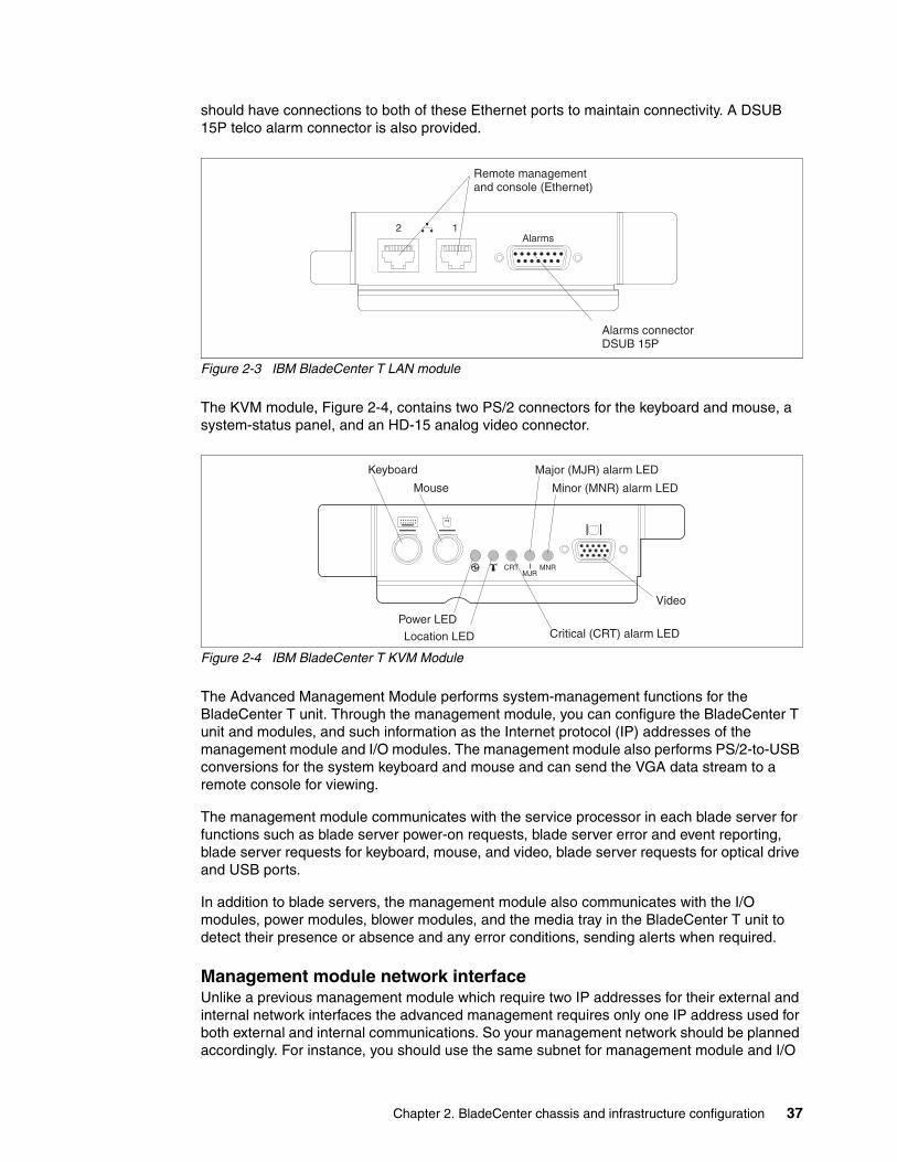
Chapter 2. BladeCenter chassis and infrastructure configuration 37
should have connections to both of these Ethernet ports to maintain connectivity. A DSUB 15P telco alarm connector is also provided.
Figure 2-3 IBM BladeCenter T LAN module
The KVM module, Figure 2-4, contains two PS/2 connectors for the keyboard and mouse, a system-status panel, and an HD-15 analog video connector.
Figure 2-4 IBM BladeCenter T KVM Module
The Advanced Management Module performs system-management functions for the BladeCenter T unit. Through the management module, you can configure the BladeCenter T unit and modules, and such information as the Internet protocol (IP) addresses of the management module and I/O modules. The management module also performs PS/2-to-USB conversions for the system keyboard and mouse and can send the VGA data stream to a remote console for viewing.
The management module communicates with the service processor in each blade server for functions such as blade server power-on requests, blade server error and event reporting, blade server requests for keyboard, mouse, and video, blade server requests for optical drive and USB ports.
In addition to blade servers, the management module also communicates with the I/O modules, power modules, blower modules, and the media tray in the BladeCenter T unit to detect their presence or absence and any error conditions, sending alerts when required.
Management module network interfaceUnlike a previous management module which require two IP addresses for their external and internal network interfaces the advanced management requires only one IP address used for both external and internal communications. So your management network should be planned accordingly. For instance, you should use the same subnet for management module and I/O
2Alarms
1
Alarms connectorDSUB 15P
Remote managementand console (Ethernet)
CRTMJR
MNR
Keyboard
Mouse
Major (MJR) alarm LED
Minor (MNR) alarm LED
Video
Critical (CRT) alarm LEDLocation LED
Power LED
38 IBM BladeCenter Products and Technology
modules management interfaces. For more information see Chapter 4, “Network integration” on page 163
Management module redundant configurationYou can configure one optional redundant Management Module for higher availability by ordering part number 32R0835.
Table 2-4 Redundant MM options for IBM BladeCenter T
Only one KVM cable is required both for single and redundant management modules because only one KVM module is in chassis.
LAN module has two Ethernet ports, as shown in Figure 2-3 on page 37. The right Ethernet port is dedicated to management module 1 and the left Ethernet port is dedicated to management module 2. In case you want to keep remote management capabilities in case of failover without reconnecting cables you should connect both interfaces to the network.
For more information about Advanced Management Module for BladeCenter T, refer to the following product documentation:
� IBM BladeCenter Advanced Management Module for BladeCenter T Installation Guide
� IBM BladeCenter Advanced Management Module User's Guide
� Advanced Management Module Command Line Interface Reference Guide
For more information about hardware management features, refer to the IBM Redbook IBM eServer xSeries and BladeCenter Server Management, SG24-6495.
2.2 Blower modules
Each of the three BladeCenter chassis have unique blower modules.
Note: We recommend to use static IP addresses (or at least reservations for DHCP) for the Management Module to avoid some management issues
Part Number Description
32R0835 IBM BladeCenter T Advanced Management Module
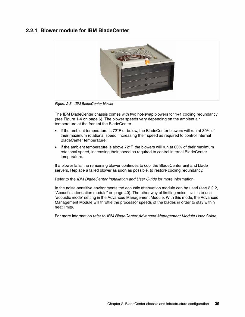
Chapter 2. BladeCenter chassis and infrastructure configuration 39
2.2.1 Blower module for IBM BladeCenter
Figure 2-5 IBM BladeCenter blower
The IBM BladeCenter chassis comes with two hot-swap blowers for 1+1 cooling redundancy (see Figure 1-4 on page 6). The blower speeds vary depending on the ambient air temperature at the front of the BladeCenter:
� If the ambient temperature is 72°F or below, the BladeCenter blowers will run at 30% of their maximum rotational speed, increasing their speed as required to control internal BladeCenter temperature.
� If the ambient temperature is above 72°F, the blowers will run at 80% of their maximum rotational speed, increasing their speed as required to control internal BladeCenter temperature.
If a blower fails, the remaining blower continues to cool the BladeCenter unit and blade servers. Replace a failed blower as soon as possible, to restore cooling redundancy.
Refer to the IBM BladeCenter Installation and User Guide for more information.
In the noise-sensitive environments the acoustic attenuation module can be used (see 2.2.2, “Acoustic attenuation module” on page 40). The other way of limiting noise level is to use “acoustic mode” setting in the Advanced Management Module. With this mode, the Advanced Management Module will throttle the processor speeds of the blades in order to stay within heat limits.
For more information refer to IBM BladeCenter Advanced Management Module User Guide.
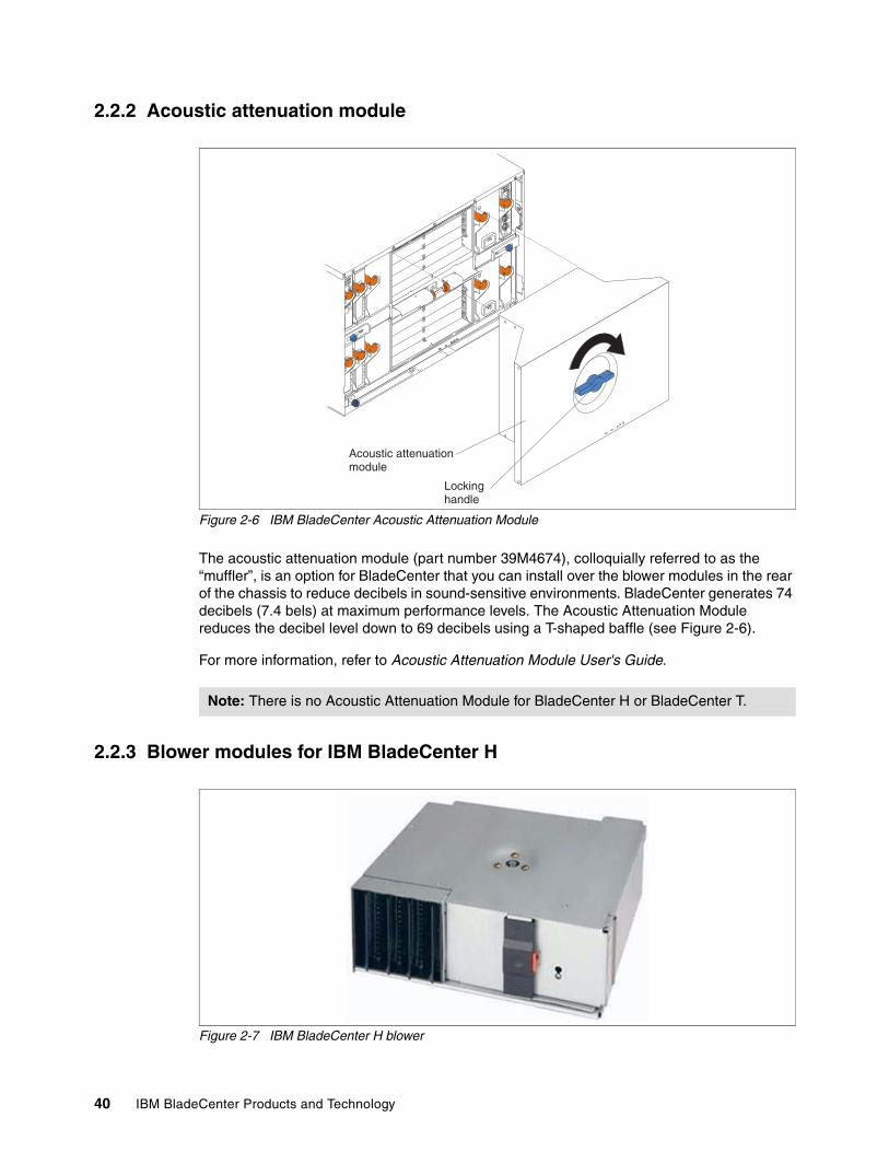
40 IBM BladeCenter Products and Technology
2.2.2 Acoustic attenuation module
Figure 2-6 IBM BladeCenter Acoustic Attenuation Module
The acoustic attenuation module (part number 39M4674), colloquially referred to as the “muffler”, is an option for BladeCenter that you can install over the blower modules in the rear of the chassis to reduce decibels in sound-sensitive environments. BladeCenter generates 74 decibels (7.4 bels) at maximum performance levels. The Acoustic Attenuation Module reduces the decibel level down to 69 decibels using a T-shaped baffle (see Figure 2-6).
For more information, refer to Acoustic Attenuation Module User's Guide.
2.2.3 Blower modules for IBM BladeCenter H
Figure 2-7 IBM BladeCenter H blower
Note: There is no Acoustic Attenuation Module for BladeCenter H or BladeCenter T.
Acoustic attenuationmodule
Lockinghandle
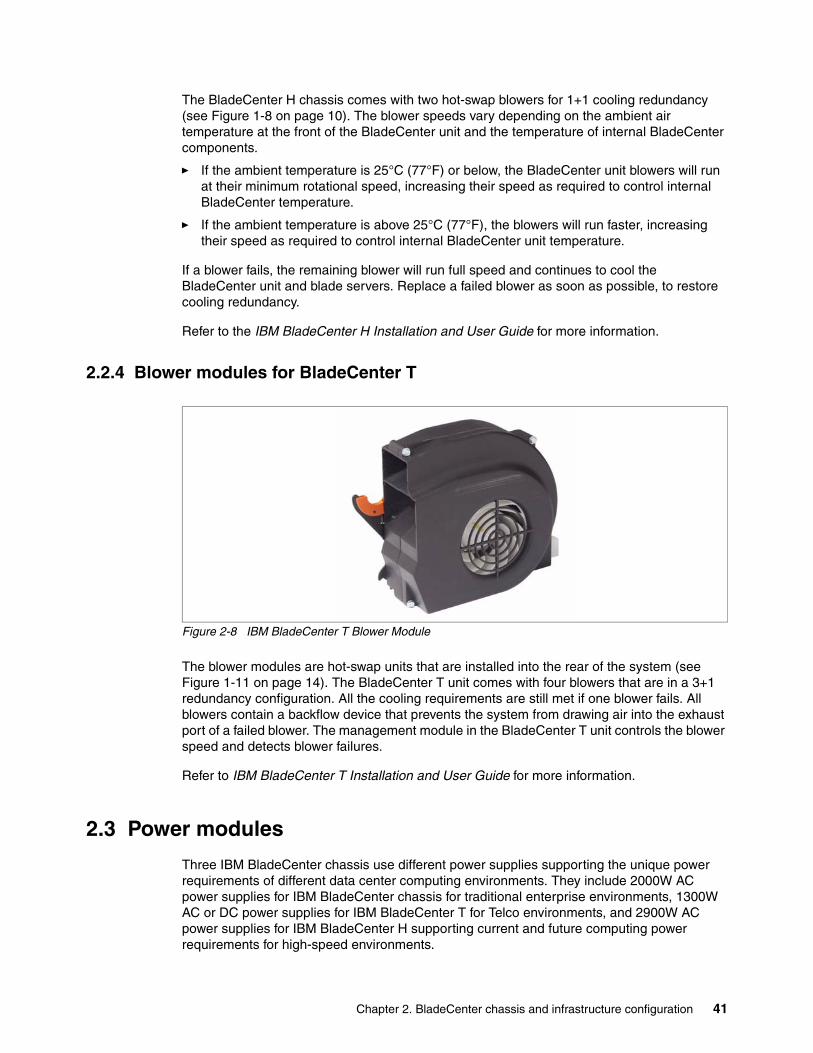
Chapter 2. BladeCenter chassis and infrastructure configuration 41
The BladeCenter H chassis comes with two hot-swap blowers for 1+1 cooling redundancy (see Figure 1-8 on page 10). The blower speeds vary depending on the ambient air temperature at the front of the BladeCenter unit and the temperature of internal BladeCenter components.
� If the ambient temperature is 25°C (77°F) or below, the BladeCenter unit blowers will run at their minimum rotational speed, increasing their speed as required to control internal BladeCenter temperature.
� If the ambient temperature is above 25°C (77°F), the blowers will run faster, increasing their speed as required to control internal BladeCenter unit temperature.
If a blower fails, the remaining blower will run full speed and continues to cool the BladeCenter unit and blade servers. Replace a failed blower as soon as possible, to restore cooling redundancy.
Refer to the IBM BladeCenter H Installation and User Guide for more information.
2.2.4 Blower modules for BladeCenter T
Figure 2-8 IBM BladeCenter T Blower Module
The blower modules are hot-swap units that are installed into the rear of the system (see Figure 1-11 on page 14). The BladeCenter T unit comes with four blowers that are in a 3+1 redundancy configuration. All the cooling requirements are still met if one blower fails. All blowers contain a backflow device that prevents the system from drawing air into the exhaust port of a failed blower. The management module in the BladeCenter T unit controls the blower speed and detects blower failures.
Refer to IBM BladeCenter T Installation and User Guide for more information.
2.3 Power modules
Three IBM BladeCenter chassis use different power supplies supporting the unique power requirements of different data center computing environments. They include 2000W AC power supplies for IBM BladeCenter chassis for traditional enterprise environments, 1300W AC or DC power supplies for IBM BladeCenter T for Telco environments, and 2900W AC power supplies for IBM BladeCenter H supporting current and future computing power requirements for high-speed environments.
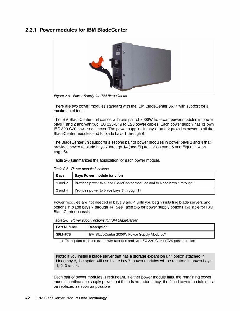
42 IBM BladeCenter Products and Technology
2.3.1 Power modules for IBM BladeCenter
Figure 2-9 Power Supply for IBM BladeCenter
There are two power modules standard with the IBM BladeCenter 8677 with support for a maximum of four.
The IBM BladeCenter unit comes with one pair of 2000W hot-swap power modules in power bays 1 and 2 and with two IEC 320-C19 to C20 power cables. Each power supply has its own IEC 320-C20 power connector. The power supplies in bays 1 and 2 provides power to all the BladeCenter modules and to blade bays 1 through 6.
The BladeCenter unit supports a second pair of power modules in power bays 3 and 4 that provides power to blade bays 7 through 14 (see Figure 1-2 on page 5 and Figure 1-4 on page 6).
Table 2-5 summarizes the application for each power module.
Table 2-5 Power module functions
Power modules are not needed in bays 3 and 4 until you begin installing blade servers and options in blade bays 7 through 14. See Table 2-6 for power supply options available for IBM BladeCenter chassis.
Table 2-6 Power supply options for IBM BladeCenter
Each pair of power modules is redundant. If either power module fails, the remaining power module continues to supply power, but there is no redundancy; the failed power module must be replaced as soon as possible.
Bays Bays Power module function
1 and 2 Provides power to all the BladeCenter modules and to blade bays 1 through 6
3 and 4 Provides power to blade bays 7 through 14
Part Number Description
39M4675 IBM BladeCenter 2000W Power Supply Modulesa
a. This option contains two power supplies and two IEC 320-C19 to C20 power cables
Note: If you install a blade server that has a storage expansion unit option attached in blade bay 6, the option will use blade bay 7; power modules will be required in power bays 1, 2, 3 and 4.
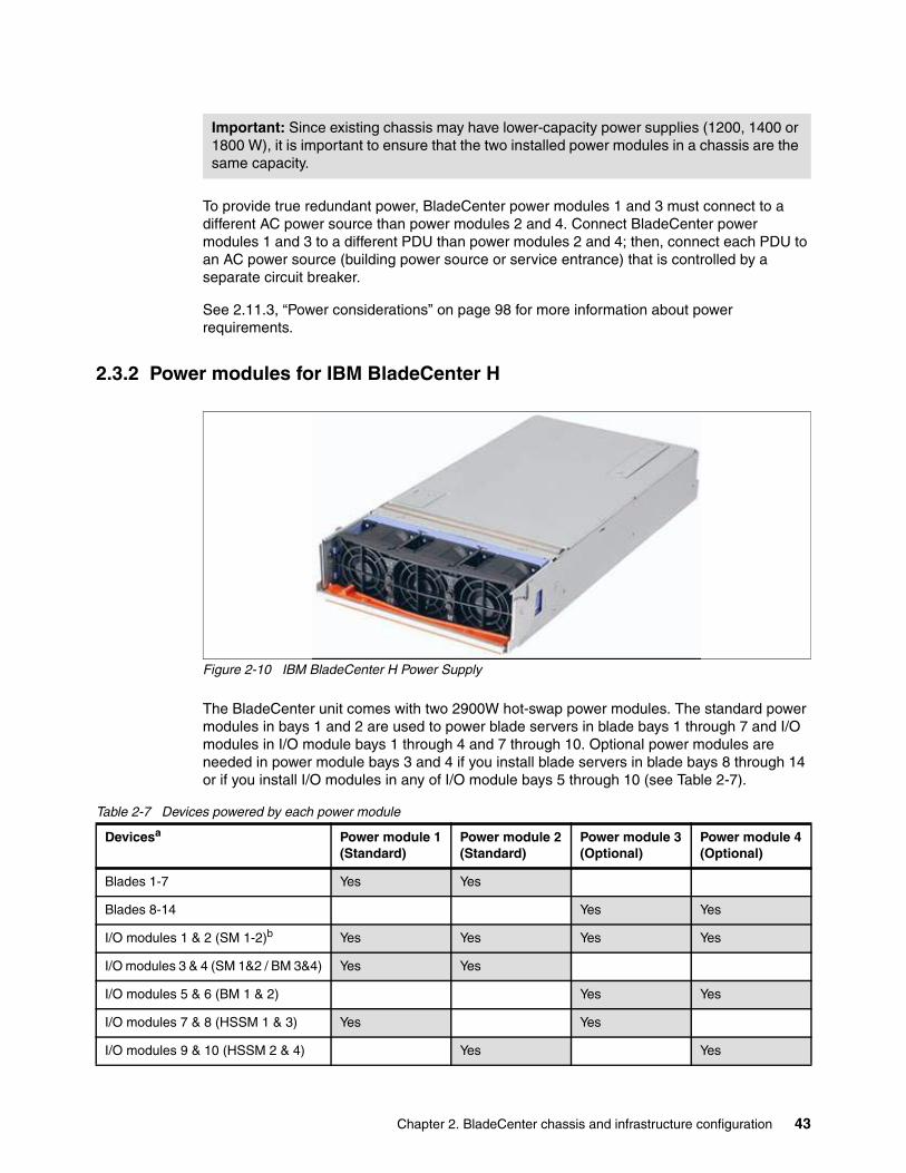
Chapter 2. BladeCenter chassis and infrastructure configuration 43
To provide true redundant power, BladeCenter power modules 1 and 3 must connect to a different AC power source than power modules 2 and 4. Connect BladeCenter power modules 1 and 3 to a different PDU than power modules 2 and 4; then, connect each PDU to an AC power source (building power source or service entrance) that is controlled by a separate circuit breaker.
See 2.11.3, “Power considerations” on page 98 for more information about power requirements.
2.3.2 Power modules for IBM BladeCenter H
Figure 2-10 IBM BladeCenter H Power Supply
The BladeCenter unit comes with two 2900W hot-swap power modules. The standard power modules in bays 1 and 2 are used to power blade servers in blade bays 1 through 7 and I/O modules in I/O module bays 1 through 4 and 7 through 10. Optional power modules are needed in power module bays 3 and 4 if you install blade servers in blade bays 8 through 14 or if you install I/O modules in any of I/O module bays 5 through 10 (see Table 2-7).
Table 2-7 Devices powered by each power module
Important: Since existing chassis may have lower-capacity power supplies (1200, 1400 or 1800 W), it is important to ensure that the two installed power modules in a chassis are the same capacity.
Devicesa Power module 1(Standard)
Power module 2(Standard)
Power module 3(Optional)
Power module 4(Optional)
Blades 1-7 Yes Yes
Blades 8-14 Yes Yes
I/O modules 1 & 2 (SM 1-2)b Yes Yes Yes Yes
I/O modules 3 & 4 (SM 1&2 / BM 3&4) Yes Yes
I/O modules 5 & 6 (BM 1 & 2) Yes Yes
I/O modules 7 & 8 (HSSM 1 & 3) Yes Yes
I/O modules 9 & 10 (HSSM 2 & 4) Yes Yes
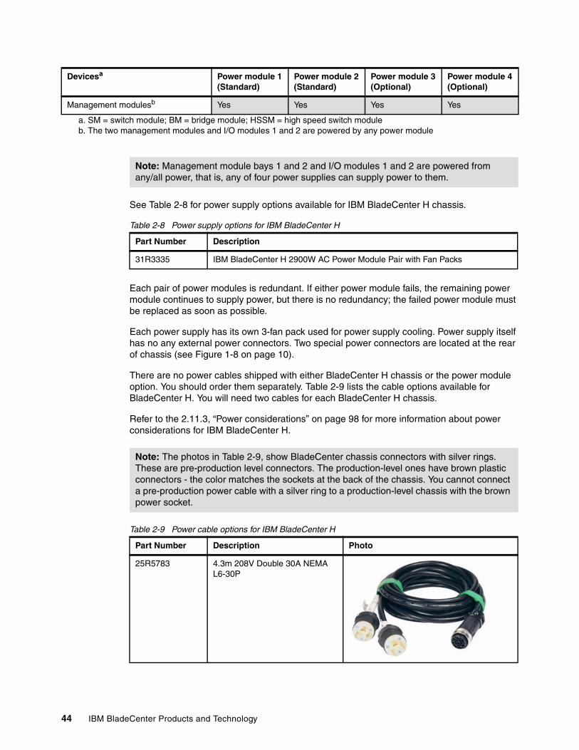
44 IBM BladeCenter Products and Technology
See Table 2-8 for power supply options available for IBM BladeCenter H chassis.
Table 2-8 Power supply options for IBM BladeCenter H
Each pair of power modules is redundant. If either power module fails, the remaining power module continues to supply power, but there is no redundancy; the failed power module must be replaced as soon as possible.
Each power supply has its own 3-fan pack used for power supply cooling. Power supply itself has no any external power connectors. Two special power connectors are located at the rear of chassis (see Figure 1-8 on page 10).
There are no power cables shipped with either BladeCenter H chassis or the power module option. You should order them separately. Table 2-9 lists the cable options available for BladeCenter H. You will need two cables for each BladeCenter H chassis.
Refer to the 2.11.3, “Power considerations” on page 98 for more information about power considerations for IBM BladeCenter H.
Table 2-9 Power cable options for IBM BladeCenter H
Management modulesb Yes Yes Yes Yes
a. SM = switch module; BM = bridge module; HSSM = high speed switch moduleb. The two management modules and I/O modules 1 and 2 are powered by any power module
Devicesa Power module 1(Standard)
Power module 2(Standard)
Power module 3(Optional)
Power module 4(Optional)
Note: Management module bays 1 and 2 and I/O modules 1 and 2 are powered from any/all power, that is, any of four power supplies can supply power to them.
Part Number Description
31R3335 IBM BladeCenter H 2900W AC Power Module Pair with Fan Packs
Note: The photos in Table 2-9, show BladeCenter chassis connectors with silver rings. These are pre-production level connectors. The production-level ones have brown plastic connectors - the color matches the sockets at the back of the chassis. You cannot connect a pre-production power cable with a silver ring to a production-level chassis with the brown power socket.
Part Number Description Photo
25R5783 4.3m 208V Double 30A NEMA L6-30P
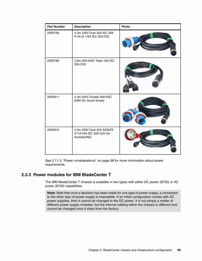
Chapter 2. BladeCenter chassis and infrastructure configuration 45
See 2.11.3, “Power considerations” on page 98 for more information about power requirements.
2.3.3 Power modules for IBM BladeCenter T
The IBM BladeCenter T chassis is available in two types with either DC power (8720) or AC power (8730) capabilities.
25R5784 4.3m 230V Dual 32A IEC 309 P+N+G /16A IEC 320-C20
25R5785 2.8m 200-240V Triple 16A IEC 320-C20
25R5811 4.3m 220V Double 30A KSC 8305 (for South Korea)
25R5812 4.3m 230V Dual 32A AS/NZS 3112/16A IEC 320-C20 (for Australia/NZ)
Part Number Description Photo
Note: Note that once a decision has been made for one type of power supply, a conversion to the other type of power supply is impossible. If an initial configuration comes with AC power supplies, then it cannot be changed to the DC power. It is not simply a matter of different power supply modules, but the internal cabling within the chassis is different and cannot be changed once it ships from the factory.
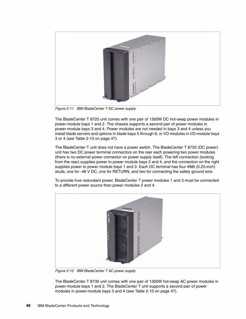
46 IBM BladeCenter Products and Technology
Figure 2-11 IBM BladeCenter T DC power supply
The BladeCenter T 8720 unit comes with one pair of 1300W DC hot-swap power modules in power-module bays 1 and 2. The chassis supports a second pair of power modules in power-module bays 3 and 4. Power modules are not needed in bays 3 and 4 unless you install blade servers and options in blade bays 5 through 8, or I/O modules in I/O-module bays 3 or 4 (see Table 2-10 on page 47).
The BladeCenter T unit does not have a power switch. The BladeCenter T 8720 (DC power) unit has two DC power terminal connectors on the rear each powering two power modules (there is no external power connector on power supply itself). The left connection (looking from the rear) supplies power to power module bays 2 and 4, and the connection on the right supplies power to power module bays 1 and 3. Each DC terminal has four #M6 (0.25-inch) studs, one for -48 V DC, one for RETURN, and two for connecting the safety ground wire.
To provide true redundant power, BladeCenter T power modules 1 and 3 must be connected to a different power source than power modules 2 and 4.
Figure 2-12 IBM BladeCenter T AC power supply
The BladeCenter T 8730 unit comes with one pair of 1300W hot-swap AC power modules in power-module bays 1 and 2. The BladeCenter T unit supports a second pair of power modules in power-module bays 3 and 4 (see Table 2-10 on page 47).
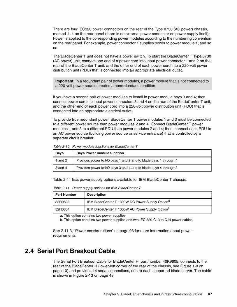
Chapter 2. BladeCenter chassis and infrastructure configuration 47
There are four IEC320 power connectors on the rear of the Type 8730 (AC power) chassis, marked 1- 4 on the rear panel (there is no external power connector on power supply itself). Power is applied to the corresponding power modules according to the numbering convention on the rear panel. For example, power connector 1 supplies power to power module 1, and so on.
The BladeCenter T unit does not have a power switch. To start the BladeCenter T Type 8730 (AC power) unit, connect one end of a power cord into input power connector 1 and 2 on the rear of the BladeCenter T unit, and the other end of each power cord into a 220-volt power distribution unit (PDU) that is connected into an appropriate electrical outlet.
If you have a second pair of power modules to install in power-module bays 3 and 4; then, connect power cords to input power connectors 3 and 4 on the rear of the BladeCenter T unit, and the other end of each power cord into a 220-volt power distribution unit (PDU) that is connected into an appropriate electrical outlet.
To provide true redundant power, BladeCenter T power modules 1 and 3 must be connected to a different power source than power modules 2 and 4. Connect BladeCenter T power modules 1 and 3 to a different PDU than power modules 2 and 4; then, connect each PDU to an AC power source (building power source or service entrance) that is controlled by a separate circuit breaker.
Table 2-10 Power module functions for BladeCenter T
Table 2-11 lists power supply options available for IBM BladeCenter T chassis.
Table 2-11 Power supply options for IBM BladeCenter T
See 2.11.3, “Power considerations” on page 98 for more information about power requirements.
2.4 Serial Port Breakout Cable
The Serial Port Breakout Cable for BladeCenter H, part number 40K9605, connects to the rear of the BladeCenter H (lower-left corner of the rear of the chassis, see Figure 1-8 on page 10) and provides 14 serial connections, one to each supported blade server. The cable is shown in Figure 2-13 on page 48.
Important: In a redundant pair of power modules, a power module that is not connected to a 220-volt power source creates a nonredundant condition.
Bays Bays Power module function
1 and 2 Provides power to I/O bays 1 and 2 and to blade bays 1 through 4
3 and 4 Provides power to I/O bays 3 and 4 and to blade bays 4 through 8
Part Number Description
32R0833 IBM BladeCenter T 1300W DC Power Supply Optiona
a. This option contains two power supplies
32R0834 IBM BladeCenter T 1300W AC Power Supply Optionb
b. This option contains two power supplies and two IEC 320-C13 to C14 power cables
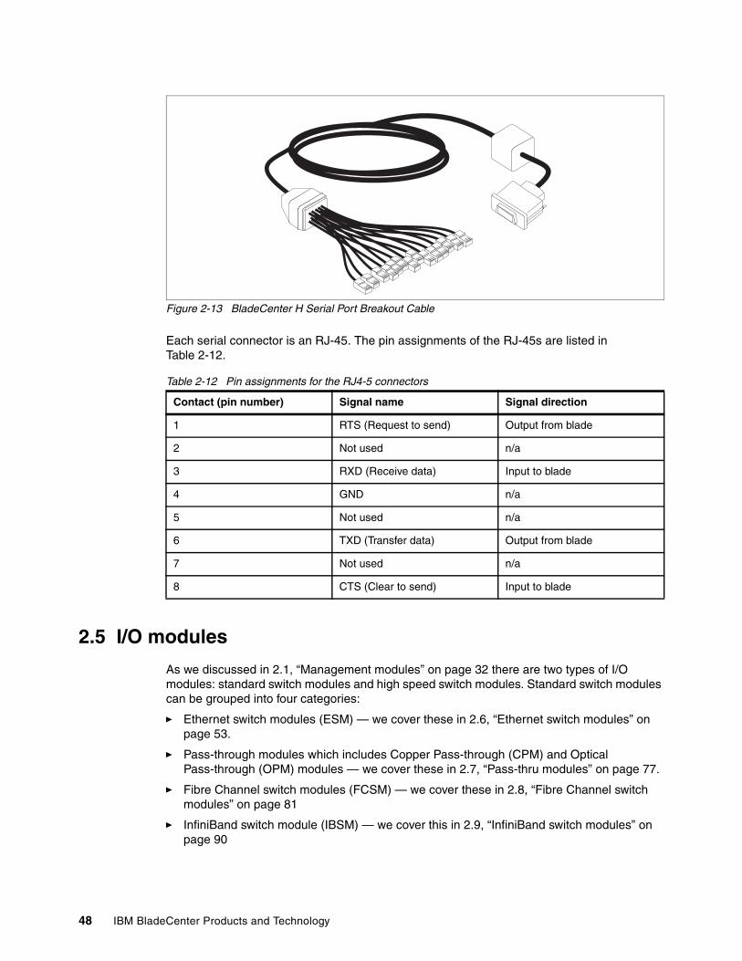
48 IBM BladeCenter Products and Technology
Figure 2-13 BladeCenter H Serial Port Breakout Cable
Each serial connector is an RJ-45. The pin assignments of the RJ-45s are listed in Table 2-12.
Table 2-12 Pin assignments for the RJ4-5 connectors
2.5 I/O modules
As we discussed in 2.1, “Management modules” on page 32 there are two types of I/O modules: standard switch modules and high speed switch modules. Standard switch modules can be grouped into four categories:
� Ethernet switch modules (ESM) — we cover these in 2.6, “Ethernet switch modules” on page 53.
� Pass-through modules which includes Copper Pass-through (CPM) and Optical Pass-through (OPM) modules — we cover these in 2.7, “Pass-thru modules” on page 77.
� Fibre Channel switch modules (FCSM) — we cover these in 2.8, “Fibre Channel switch modules” on page 81
� InfiniBand switch module (IBSM) — we cover this in 2.9, “InfiniBand switch modules” on page 90
Contact (pin number) Signal name Signal direction
1 RTS (Request to send) Output from blade
2 Not used n/a
3 RXD (Receive data) Input to blade
4 GND n/a
5 Not used n/a
6 TXD (Transfer data) Output from blade
7 Not used n/a
8 CTS (Clear to send) Input to blade
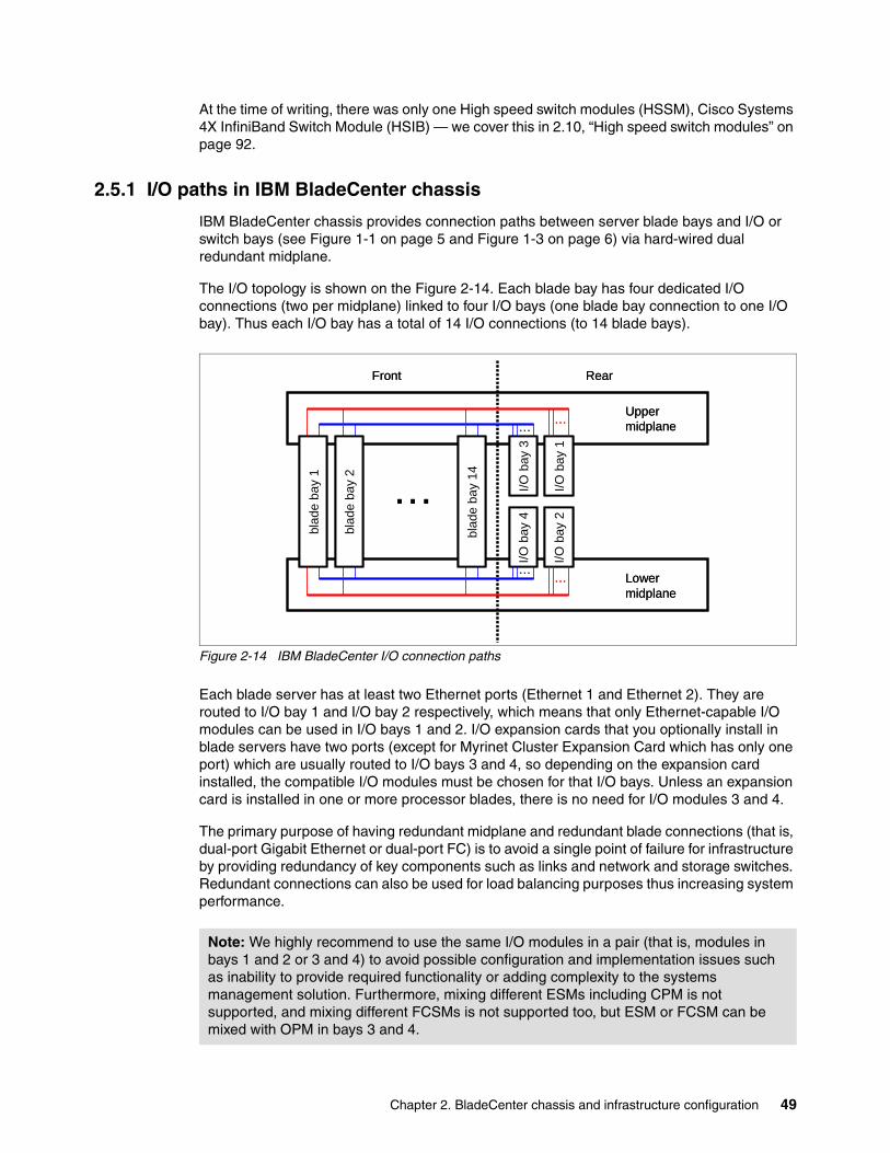
Chapter 2. BladeCenter chassis and infrastructure configuration 49
At the time of writing, there was only one High speed switch modules (HSSM), Cisco Systems 4X InfiniBand Switch Module (HSIB) — we cover this in 2.10, “High speed switch modules” on page 92.
2.5.1 I/O paths in IBM BladeCenter chassis
IBM BladeCenter chassis provides connection paths between server blade bays and I/O or switch bays (see Figure 1-1 on page 5 and Figure 1-3 on page 6) via hard-wired dual redundant midplane.
The I/O topology is shown on the Figure 2-14. Each blade bay has four dedicated I/O connections (two per midplane) linked to four I/O bays (one blade bay connection to one I/O bay). Thus each I/O bay has a total of 14 I/O connections (to 14 blade bays).
Figure 2-14 IBM BladeCenter I/O connection paths
Each blade server has at least two Ethernet ports (Ethernet 1 and Ethernet 2). They are routed to I/O bay 1 and I/O bay 2 respectively, which means that only Ethernet-capable I/O modules can be used in I/O bays 1 and 2. I/O expansion cards that you optionally install in blade servers have two ports (except for Myrinet Cluster Expansion Card which has only one port) which are usually routed to I/O bays 3 and 4, so depending on the expansion card installed, the compatible I/O modules must be chosen for that I/O bays. Unless an expansion card is installed in one or more processor blades, there is no need for I/O modules 3 and 4.
The primary purpose of having redundant midplane and redundant blade connections (that is, dual-port Gigabit Ethernet or dual-port FC) is to avoid a single point of failure for infrastructure by providing redundancy of key components such as links and network and storage switches. Redundant connections can also be used for load balancing purposes thus increasing system performance.
Note: We highly recommend to use the same I/O modules in a pair (that is, modules in bays 1 and 2 or 3 and 4) to avoid possible configuration and implementation issues such as inability to provide required functionality or adding complexity to the systems management solution. Furthermore, mixing different ESMs including CPM is not supported, and mixing different FCSMs is not supported too, but ESM or FCSM can be mixed with OPM in bays 3 and 4.
I/O b
ay 1
I/O b
ay 3
I/O b
ay 2
I/O b
ay 4
blad
e ba
y 1
blad
e ba
y 2
blad
e ba
y 14…
……
……
Front Rear
Upper midplane
Lower midplane
I/O b
ay 1
I/O b
ay 3
I/O b
ay 2
I/O b
ay 4
blad
e ba
y 1
blad
e ba
y 2
blad
e ba
y 14…
……
……
Front Rear
Upper midplane
Lower midplane
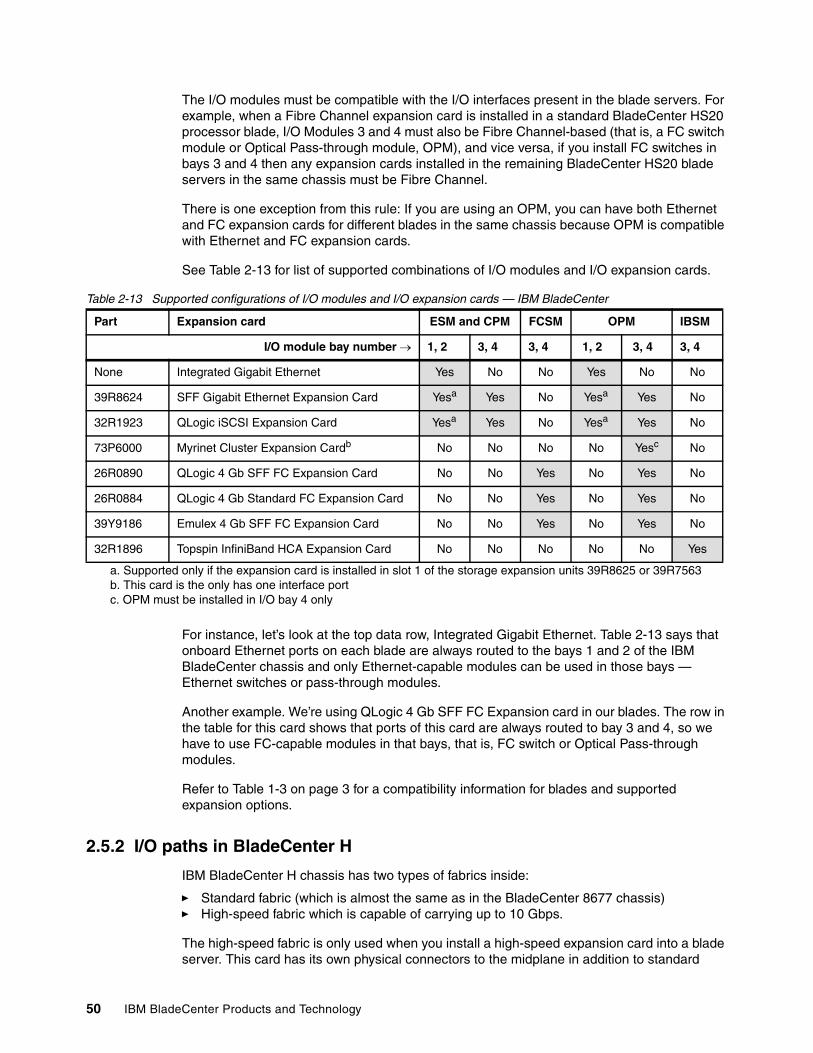
50 IBM BladeCenter Products and Technology
The I/O modules must be compatible with the I/O interfaces present in the blade servers. For example, when a Fibre Channel expansion card is installed in a standard BladeCenter HS20 processor blade, I/O Modules 3 and 4 must also be Fibre Channel-based (that is, a FC switch module or Optical Pass-through module, OPM), and vice versa, if you install FC switches in bays 3 and 4 then any expansion cards installed in the remaining BladeCenter HS20 blade servers in the same chassis must be Fibre Channel.
There is one exception from this rule: If you are using an OPM, you can have both Ethernet and FC expansion cards for different blades in the same chassis because OPM is compatible with Ethernet and FC expansion cards.
See Table 2-13 for list of supported combinations of I/O modules and I/O expansion cards.
Table 2-13 Supported configurations of I/O modules and I/O expansion cards — IBM BladeCenter
For instance, let’s look at the top data row, Integrated Gigabit Ethernet. Table 2-13 says that onboard Ethernet ports on each blade are always routed to the bays 1 and 2 of the IBM BladeCenter chassis and only Ethernet-capable modules can be used in those bays — Ethernet switches or pass-through modules.
Another example. We’re using QLogic 4 Gb SFF FC Expansion card in our blades. The row in the table for this card shows that ports of this card are always routed to bay 3 and 4, so we have to use FC-capable modules in that bays, that is, FC switch or Optical Pass-through modules.
Refer to Table 1-3 on page 3 for a compatibility information for blades and supported expansion options.
2.5.2 I/O paths in BladeCenter H
IBM BladeCenter H chassis has two types of fabrics inside:
� Standard fabric (which is almost the same as in the BladeCenter 8677 chassis) � High-speed fabric which is capable of carrying up to 10 Gbps.
The high-speed fabric is only used when you install a high-speed expansion card into a blade server. This card has its own physical connectors to the midplane in addition to standard
Part Expansion card ESM and CPM FCSM OPM IBSM
I/O module bay number → 1, 2 3, 4 3, 4 1, 2 3, 4 3, 4
None Integrated Gigabit Ethernet Yes No No Yes No No
39R8624 SFF Gigabit Ethernet Expansion Card Yesa
a. Supported only if the expansion card is installed in slot 1 of the storage expansion units 39R8625 or 39R7563
Yes No Yesa Yes No
32R1923 QLogic iSCSI Expansion Card Yesa Yes No Yesa Yes No
73P6000 Myrinet Cluster Expansion Cardb
b. This card is the only has one interface port
No No No No Yesc
c. OPM must be installed in I/O bay 4 only
No
26R0890 QLogic 4 Gb SFF FC Expansion Card No No Yes No Yes No
26R0884 QLogic 4 Gb Standard FC Expansion Card No No Yes No Yes No
39Y9186 Emulex 4 Gb SFF FC Expansion Card No No Yes No Yes No
32R1896 Topspin InfiniBand HCA Expansion Card No No No No No Yes
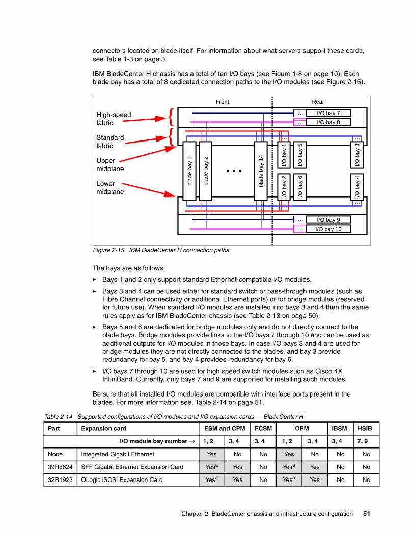
Chapter 2. BladeCenter chassis and infrastructure configuration 51
connectors located on blade itself. For information about what servers support these cards, see Table 1-3 on page 3.
IBM BladeCenter H chassis has a total of ten I/O bays (see Figure 1-8 on page 10). Each blade bay has a total of 8 dedicated connection paths to the I/O modules (see Figure 2-15).
Figure 2-15 IBM BladeCenter H connection paths
The bays are as follows:
� Bays 1 and 2 only support standard Ethernet-compatible I/O modules.
� Bays 3 and 4 can be used either for standard switch or pass-through modules (such as Fibre Channel connectivity or additional Ethernet ports) or for bridge modules (reserved for future use). When standard I/O modules are installed into bays 3 and 4 then the same rules apply as for IBM BladeCenter chassis (see Table 2-13 on page 50).
� Bays 5 and 6 are dedicated for bridge modules only and do not directly connect to the blade bays. Bridge modules provide links to the I/O bays 7 through 10 and can be used as additional outputs for I/O modules in those bays. In case I/O bays 3 and 4 are used for bridge modules they are not directly connected to the blades, and bay 3 provide redundancy for bay 5, and bay 4 provides redundancy for bay 6.
� I/O bays 7 through 10 are used for high speed switch modules such as Cisco 4X InfiniBand. Currently, only bays 7 and 9 are supported for installing such modules.
Be sure that all installed I/O modules are compatible with interface ports present in the blades. For more information see, Table 2-14 on page 51.
Table 2-14 Supported configurations of I/O modules and I/O expansion cards — BladeCenter H
I/O b
ay 5
I/O b
ay 6
…
… …
……
Front Rear
I/O b
ay 3
I/O b
ay 4
I/O b
ay 1
I/O b
ay 2
… I/O bay 8
… I/O bay 7
… I/O bay 10
… I/O bay 9
blad
e ba
y 2
blad
e ba
y 1
blad
e ba
y 14
I/O b
ay 5
I/O b
ay 6
…
… …
……
Front Rear
I/O b
ay 3
I/O b
ay 4
I/O b
ay 1
I/O b
ay 2
… I/O bay 8
… I/O bay 7
… I/O bay 10
… I/O bay 9
blad
e ba
y 2
blad
e ba
y 1
blad
e ba
y 14
High-speed fabric
Standard fabric
Upper midplane
Lower midplane
{{
Part Expansion card ESM and CPM FCSM OPM IBSM HSIB
I/O module bay number → 1, 2 3, 4 3, 4 1, 2 3, 4 3, 4 7, 9
None Integrated Gigabit Ethernet Yes No No Yes No No No
39R8624 SFF Gigabit Ethernet Expansion Card Yesa Yes No Yesa Yes No No
32R1923 QLogic iSCSI Expansion Card Yesa Yes No Yesa Yes No No
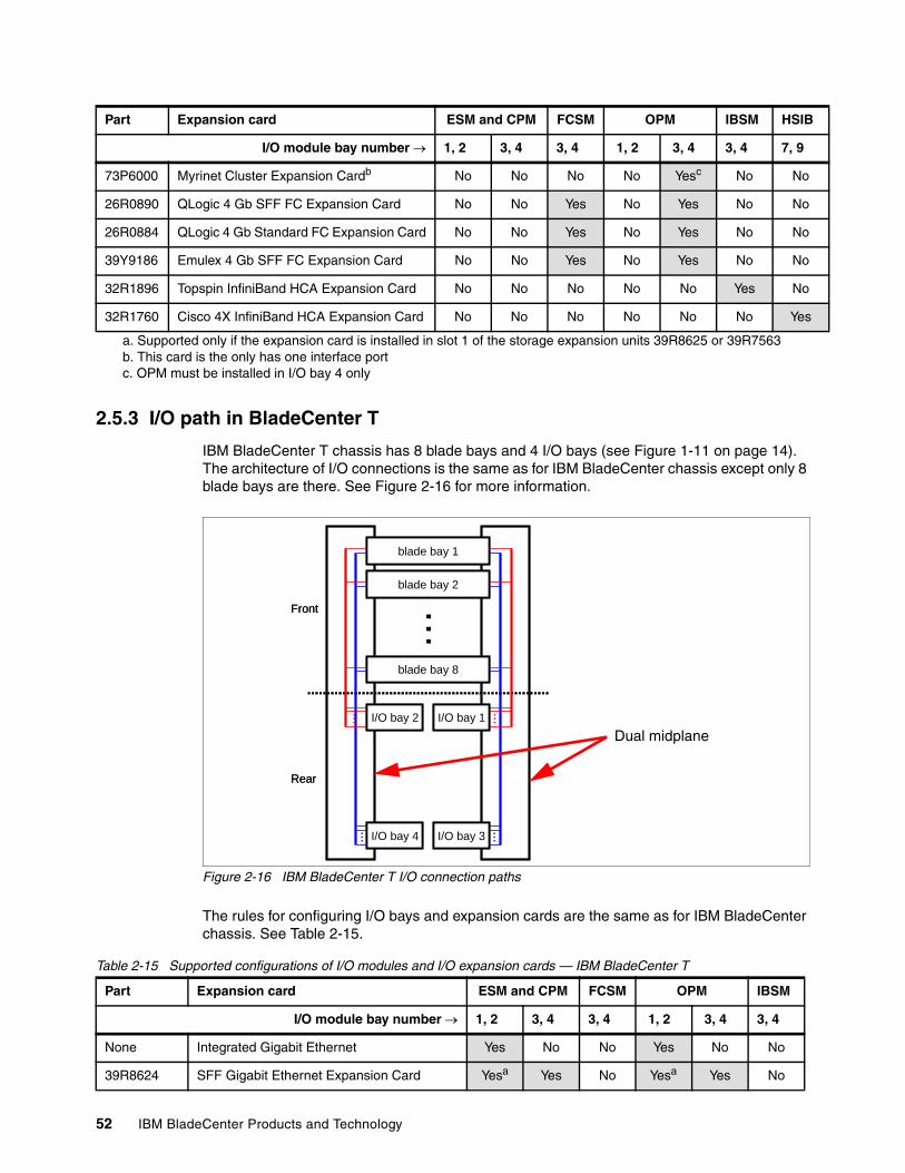
52 IBM BladeCenter Products and Technology
2.5.3 I/O path in BladeCenter T
IBM BladeCenter T chassis has 8 blade bays and 4 I/O bays (see Figure 1-11 on page 14). The architecture of I/O connections is the same as for IBM BladeCenter chassis except only 8 blade bays are there. See Figure 2-16 for more information.
Figure 2-16 IBM BladeCenter T I/O connection paths
The rules for configuring I/O bays and expansion cards are the same as for IBM BladeCenter chassis. See Table 2-15.
Table 2-15 Supported configurations of I/O modules and I/O expansion cards — IBM BladeCenter T
73P6000 Myrinet Cluster Expansion Cardb No No No No Yesc No No
26R0890 QLogic 4 Gb SFF FC Expansion Card No No Yes No Yes No No
26R0884 QLogic 4 Gb Standard FC Expansion Card No No Yes No Yes No No
39Y9186 Emulex 4 Gb SFF FC Expansion Card No No Yes No Yes No No
32R1896 Topspin InfiniBand HCA Expansion Card No No No No No Yes No
32R1760 Cisco 4X InfiniBand HCA Expansion Card No No No No No No Yes
a. Supported only if the expansion card is installed in slot 1 of the storage expansion units 39R8625 or 39R7563b. This card is the only has one interface port c. OPM must be installed in I/O bay 4 only
Part Expansion card ESM and CPM FCSM OPM IBSM HSIB
I/O module bay number → 1, 2 3, 4 3, 4 1, 2 3, 4 3, 4 7, 9
…
……
……
Front
Rear
I/O bay 3I/O bay 4
I/O bay 1I/O bay 2
blade bay 2
blade bay 1
blade bay 8
…
……
……
Front
Rear
I/O bay 3I/O bay 4
I/O bay 1I/O bay 2
blade bay 2
blade bay 1
blade bay 8
Dual midplane
Part Expansion card ESM and CPM FCSM OPM IBSM
I/O module bay number → 1, 2 3, 4 3, 4 1, 2 3, 4 3, 4
None Integrated Gigabit Ethernet Yes No No Yes No No
39R8624 SFF Gigabit Ethernet Expansion Card Yesa Yes No Yesa Yes No
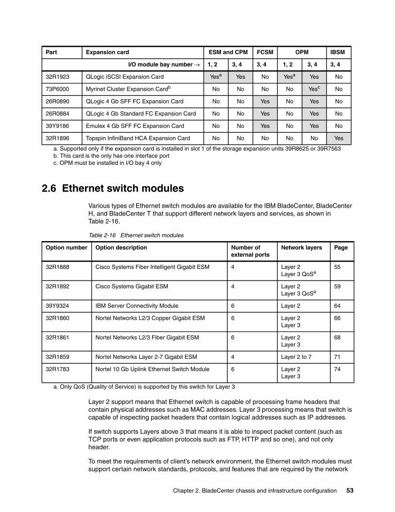
Chapter 2. BladeCenter chassis and infrastructure configuration 53
2.6 Ethernet switch modules
Various types of Ethernet switch modules are available for the IBM BladeCenter, BladeCenter H, and BladeCenter T that support different network layers and services, as shown in Table 2-16.
Table 2-16 Ethernet switch modules
Layer 2 support means that Ethernet switch is capable of processing frame headers that contain physical addresses such as MAC addresses. Layer 3 processing means that switch is capable of inspecting packet headers that contain logical addresses such as IP addresses.
If switch supports Layers above 3 that means it is able to inspect packet content (such as TCP ports or even application protocols such as FTP, HTTP and so one), and not only header.
To meet the requirements of client’s network environment, the Ethernet switch modules must support certain network standards, protocols, and features that are required by the network
32R1923 QLogic iSCSI Expansion Card Yesa Yes No Yesa Yes No
73P6000 Myrinet Cluster Expansion Cardb No No No No Yesc No
26R0890 QLogic 4 Gb SFF FC Expansion Card No No Yes No Yes No
26R0884 QLogic 4 Gb Standard FC Expansion Card No No Yes No Yes No
39Y9186 Emulex 4 Gb SFF FC Expansion Card No No Yes No Yes No
32R1896 Topspin InfiniBand HCA Expansion Card No No No No No Yes
a. Supported only if the expansion card is installed in slot 1 of the storage expansion units 39R8625 or 39R7563b. This card is the only has one interface port c. OPM must be installed in I/O bay 4 only
Part Expansion card ESM and CPM FCSM OPM IBSM
I/O module bay number → 1, 2 3, 4 3, 4 1, 2 3, 4 3, 4
Option number Option description Number of external ports
Network layers Page
32R1888 Cisco Systems Fiber Intelligent Gigabit ESM 4 Layer 2Layer 3 QoSa
55
32R1892 Cisco Systems Gigabit ESM 4 Layer 2Layer 3 QoSa
59
39Y9324 IBM Server Connectivity Module 6 Layer 2 64
32R1860 Nortel Networks L2/3 Copper Gigabit ESM 6 Layer 2Layer 3
66
32R1861 Nortel Networks L2/3 Fiber Gigabit ESM 6 Layer 2Layer 3
68
32R1859 Nortel Networks Layer 2-7 Gigabit ESM 4 Layer 2 to 7 71
32R1783 Nortel 10 Gb Uplink Ethernet Switch Module 6 Layer 2Layer 3
74
a. Only QoS (Quality of Service) is supported by this switch for Layer 3
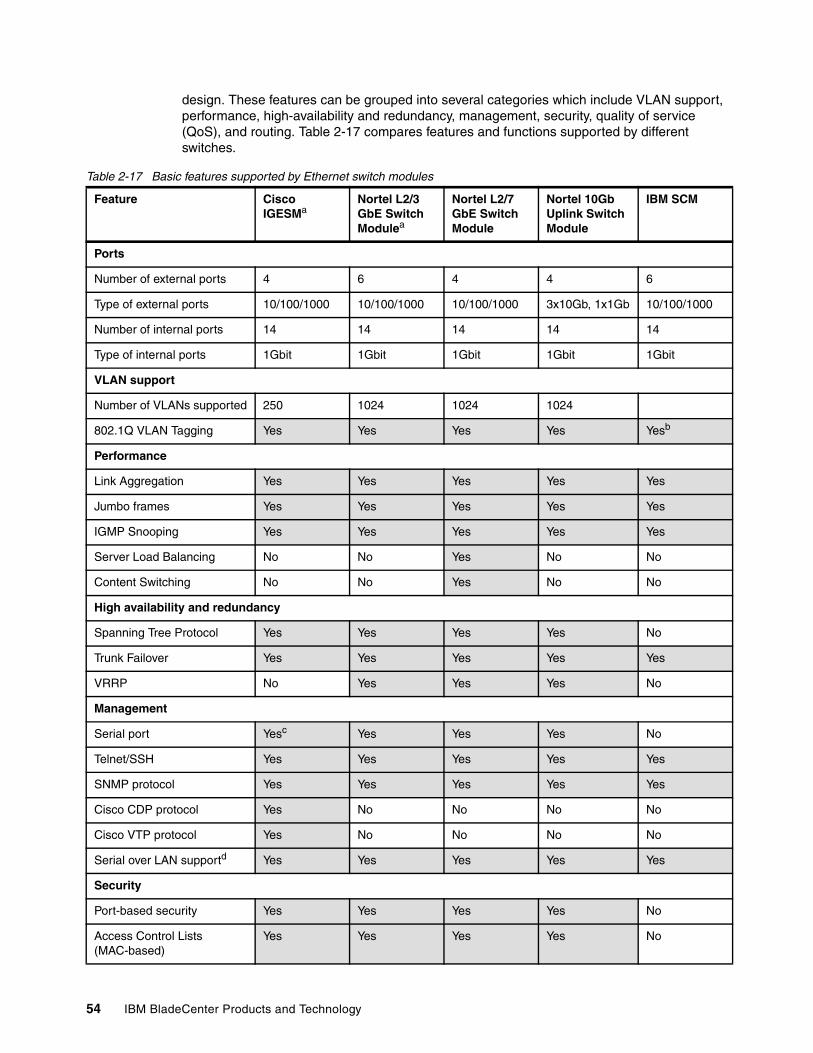
54 IBM BladeCenter Products and Technology
design. These features can be grouped into several categories which include VLAN support, performance, high-availability and redundancy, management, security, quality of service (QoS), and routing. Table 2-17 compares features and functions supported by different switches.
Table 2-17 Basic features supported by Ethernet switch modules
Feature Cisco IGESMa
Nortel L2/3 GbE Switch Modulea
Nortel L2/7 GbE Switch Module
Nortel 10Gb Uplink Switch Module
IBM SCM
Ports
Number of external ports 4 6 4 4 6
Type of external ports 10/100/1000 10/100/1000 10/100/1000 3x10Gb, 1x1Gb 10/100/1000
Number of internal ports 14 14 14 14 14
Type of internal ports 1Gbit 1Gbit 1Gbit 1Gbit 1Gbit
VLAN support
Number of VLANs supported 250 1024 1024 1024
802.1Q VLAN Tagging Yes Yes Yes Yes Yesb
Performance
Link Aggregation Yes Yes Yes Yes Yes
Jumbo frames Yes Yes Yes Yes Yes
IGMP Snooping Yes Yes Yes Yes Yes
Server Load Balancing No No Yes No No
Content Switching No No Yes No No
High availability and redundancy
Spanning Tree Protocol Yes Yes Yes Yes No
Trunk Failover Yes Yes Yes Yes Yes
VRRP No Yes Yes Yes No
Management
Serial port Yesc Yes Yes Yes No
Telnet/SSH Yes Yes Yes Yes Yes
SNMP protocol Yes Yes Yes Yes Yes
Cisco CDP protocol Yes No No No No
Cisco VTP protocol Yes No No No No
Serial over LAN supportd Yes Yes Yes Yes Yes
Security
Port-based security Yes Yes Yes Yes No
Access Control Lists (MAC-based)
Yes Yes Yes Yes No
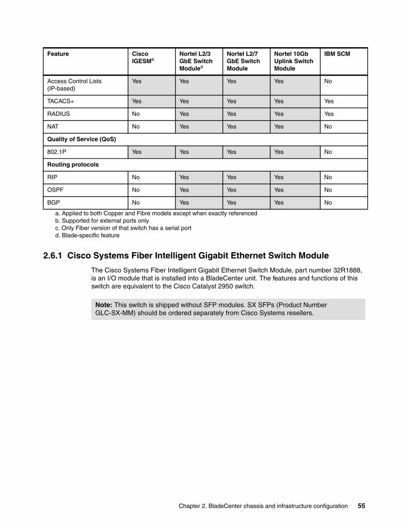
Chapter 2. BladeCenter chassis and infrastructure configuration 55
2.6.1 Cisco Systems Fiber Intelligent Gigabit Ethernet Switch Module
The Cisco Systems Fiber Intelligent Gigabit Ethernet Switch Module, part number 32R1888, is an I/O module that is installed into a BladeCenter unit. The features and functions of this switch are equivalent to the Cisco Catalyst 2950 switch.
Access Control Lists (IP-based)
Yes Yes Yes Yes No
TACACS+ Yes Yes Yes Yes Yes
RADIUS No Yes Yes Yes Yes
NAT No Yes Yes Yes No
Quality of Service (QoS)
802.1P Yes Yes Yes Yes No
Routing protocols
RIP No Yes Yes Yes No
OSPF No Yes Yes Yes No
BGP No Yes Yes Yes No
a. Applied to both Copper and Fibre models except when exactly referencedb. Supported for external ports onlyc. Only Fiber version of that switch has a serial portd. Blade-specific feature
Feature Cisco IGESMa
Nortel L2/3 GbE Switch Modulea
Nortel L2/7 GbE Switch Module
Nortel 10Gb Uplink Switch Module
IBM SCM
Note: This switch is shipped without SFP modules. SX SFPs (Product Number GLC-SX-MM) should be ordered separately from Cisco Systems resellers.
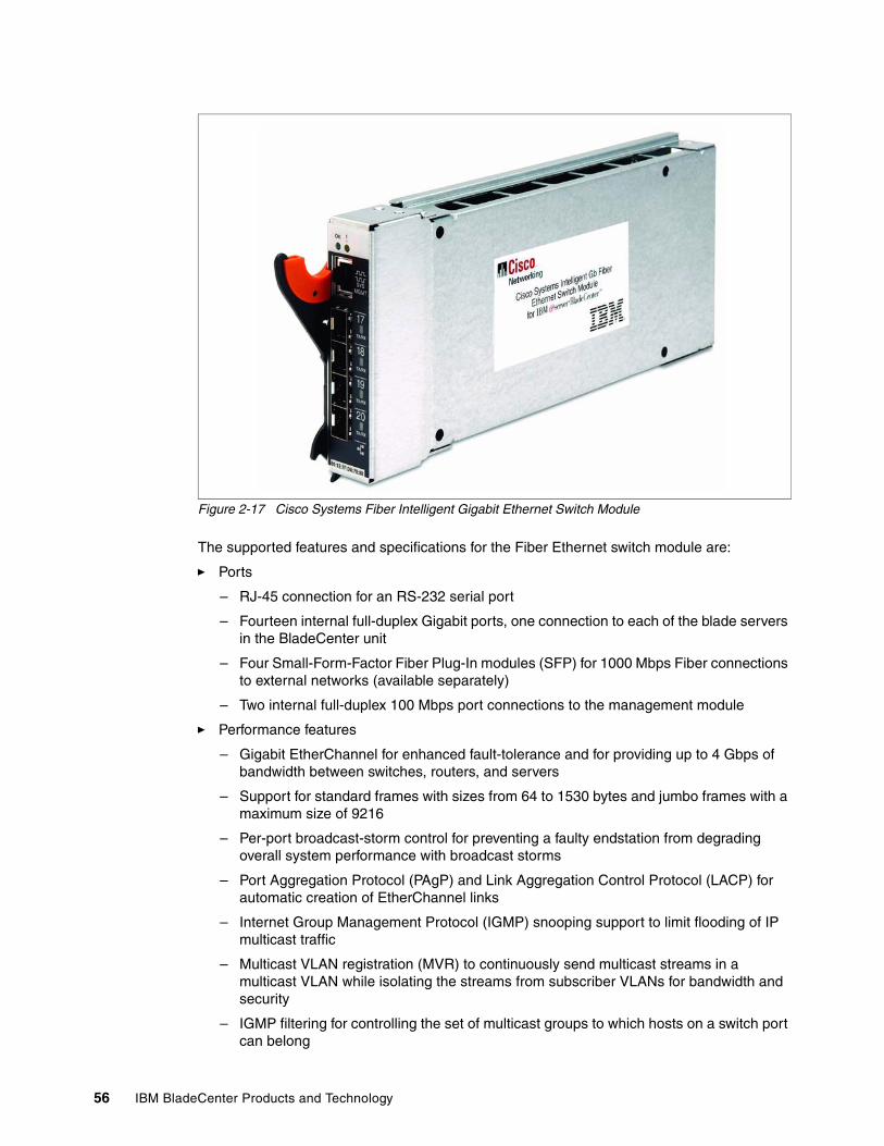
56 IBM BladeCenter Products and Technology
Figure 2-17 Cisco Systems Fiber Intelligent Gigabit Ethernet Switch Module
The supported features and specifications for the Fiber Ethernet switch module are:
� Ports
– RJ-45 connection for an RS-232 serial port
– Fourteen internal full-duplex Gigabit ports, one connection to each of the blade servers in the BladeCenter unit
– Four Small-Form-Factor Fiber Plug-In modules (SFP) for 1000 Mbps Fiber connections to external networks (available separately)
– Two internal full-duplex 100 Mbps port connections to the management module
� Performance features
– Gigabit EtherChannel for enhanced fault-tolerance and for providing up to 4 Gbps of bandwidth between switches, routers, and servers
– Support for standard frames with sizes from 64 to 1530 bytes and jumbo frames with a maximum size of 9216
– Per-port broadcast-storm control for preventing a faulty endstation from degrading overall system performance with broadcast storms
– Port Aggregation Protocol (PAgP) and Link Aggregation Control Protocol (LACP) for automatic creation of EtherChannel links
– Internet Group Management Protocol (IGMP) snooping support to limit flooding of IP multicast traffic
– Multicast VLAN registration (MVR) to continuously send multicast streams in a multicast VLAN while isolating the streams from subscriber VLANs for bandwidth and security
– IGMP filtering for controlling the set of multicast groups to which hosts on a switch port can belong

Chapter 2. BladeCenter chassis and infrastructure configuration 57
– Protected port (private VLAN edge port) option for restricting the forwarding of traffic to designated ports on the same switch
– Dynamic address learning for enhanced security
� Manageability
– Address Resolution Protocol (ARP) for identifying a switch through its IP address and its corresponding MAC address
– Cisco Discovery Protocol (CDP) versions 1 and 2 for network topology discovery and mapping between the switch and other Cisco network devices
– Network Time Protocol (NTP) for providing a consistent time stamp to all switches from an external source
– Directed unicast requests to a Trivial File Transfer Protocol (TFTP) server for obtaining software upgrades from a TFTP server
– Default configuration storage in flash memory to ensure that the switch can be connected to a network and can forward traffic with minimal user intervention
– In-band management access through the device manager Web-interface session
– In-band management access through up to 16 simultaneous Telnet connections for multiple command-line-interface (CLI) based sessions over the network
– In-band management access through up to five simultaneous, encrypted Secure Shell (SSH) connections for multiple CLI-based sessions over the network is available only in the cryptographic software image
– In-band management access through SNMP versions 1, 2c, and 3 get and set requests
� Redundancy
– Link state tracking to mirror the state of the external ports on the internal Ethernet links and to allow the failover of the processor blade traffic to an operational external link on a separate Cisco Ethernet switch
– UniDirectional link detection (UDLD) on all Ethernet ports for detecting and disabling unidirectional links caused by port faults
– IEEE 802.1D Spanning Tree Protocol (STP) for redundant backbone connections and loop-free networks
– IEEE 802.1s Multiple STP (MSTP) for grouping VLANs into a spanning-tree instance, and provided for multiple forwarding paths for data traffic and load balancing
– IEEE 802.1w Rapid STP (RSTP) for rapid convergence of the spanning tree by immediately transitioning root and designated ports to the converting state
– Optional spanning-tree features available in the PVST+, rapid PVST+, and MSTP modes
� VLAN support
– Support for 250 port-based VLANs for assigning users to VLANs associated with the applicable network resources, traffic patterns, and bandwidth
– Support for up to 4094 VLAN IDs to enable service provider networks to support the number of VLANs allowed by the IEEE 802.1Q standard
– IEEE 802.1Q trunking protocol on all ports for network moves, adds, and changes; management and control of broadcast and multicast traffic; and network security by establishing VLAN groups for high-security users and network resources
– VLAN Membership Policy Server (VMPS) for dynamic VLAN membership

58 IBM BladeCenter Products and Technology
– VLAN Trunking Protocol (VTP) pruning for reducing network traffic by restricting flooded traffic to links destined for stations receiving the traffic
– Dynamic Trunking Protocol (DTP) for negotiating trunking on a link between two devices and for negotiating the type of trunking encapsulation (802.1Q) to be used
– VLAN 1 minimization to reduce the risk of spanning-tree loops or storms by enabling VLAN 1 to be disabled on any individual VLAN trunk link. With this feature enabled, no user traffic is sent or received. The microprocessor continues to send and receive control protocol frames
� Security
– Bridge protocol data unit (BPDU) guard for shutting down a Port Fast-configured port when an invalid configuration occurs
– Protected port option for restricting the forwarding of traffic to designated ports on the same switch
– Password-protected access (read-only and write-only access) to management interfaces (the device manager and CLI) for protection against unauthorized configuration changes
– Port security option for limiting and identifying MAC addresses of the station allowed to access the port
– Port security aging to set the aging time for secure addresses on a port
– Multilevel security for a choice of security level, notification, and resulting actions
– MAC-based port-level security for restricting the use of a switch port to a specific group of source addresses and preventing switch access from unauthorized stations
– Terminal Access Controller Access Control System Plus (TACACS+), a proprietary feature for managing network security through a TACACS server
– IEEE 802.1X port-based authentication to prevent unauthorized devices from gaining access to the network
– IEEE 802.1X port-based authentication with VLAN assignment for restricting 802.1X-authenticated users to a specified VLAN
– IEEE 802.1X port-based authentication with port security for authenticating the port and managing network access for all MAC addresses, including that of the client
– IEEE 802.1X port-based authentication with voice VLAN to allow an IP phone access to the voice VLAN irrespective of the authorized or unauthorized state of the port
– IEEE 802.1X port-based authentication with guest VLAN to provided limited services to non-802.1X-compliant users
– Standard and extended IP access control lists (ACLs) for defining security policies
� Quality of Service (QoS) and Class of Service (CoS)
– Classification - IEEE 802.1p CoS with eight priority queues on the Fiber Ethernet ports for prioritizing mission-critical and time-sensitive traffic from data, voice, and telephony applications
– IP Differentiated Services Code Point (IP DSCP) and CoS marking priorities on a per-port basis for protecting the performance of mission-critical applications
– Flow-based packet classification (classification based on information in the MAC, IP, and TCP/UDP headers) for high-performance QoS at the network edge, allowing for differentiated service levels for different types of network traffic and for prioritizing mission-critical traffic in the network
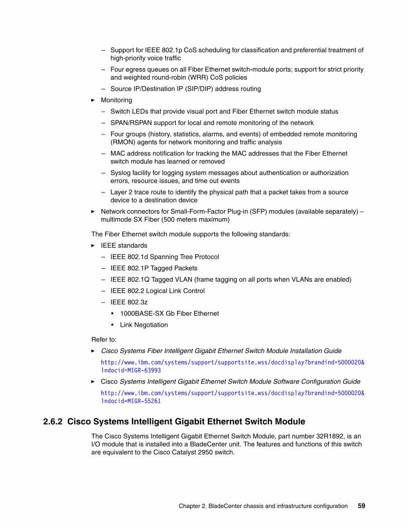
Chapter 2. BladeCenter chassis and infrastructure configuration 59
– Support for IEEE 802.1p CoS scheduling for classification and preferential treatment of high-priority voice traffic
– Four egress queues on all Fiber Ethernet switch-module ports; support for strict priority and weighted round-robin (WRR) CoS policies
– Source IP/Destination IP (SIP/DIP) address routing
� Monitoring
– Switch LEDs that provide visual port and Fiber Ethernet switch module status
– SPAN/RSPAN support for local and remote monitoring of the network
– Four groups (history, statistics, alarms, and events) of embedded remote monitoring (RMON) agents for network monitoring and traffic analysis
– MAC address notification for tracking the MAC addresses that the Fiber Ethernet switch module has learned or removed
– Syslog facility for logging system messages about authentication or authorization errors, resource issues, and time out events
– Layer 2 trace route to identify the physical path that a packet takes from a source device to a destination device
� Network connectors for Small-Form-Factor Plug-in (SFP) modules (available separately) – multimode SX Fiber (500 meters maximum)
The Fiber Ethernet switch module supports the following standards:
� IEEE standards
– IEEE 802.1d Spanning Tree Protocol
– IEEE 802.1P Tagged Packets
– IEEE 802.1Q Tagged VLAN (frame tagging on all ports when VLANs are enabled)
– IEEE 802.2 Logical Link Control
– IEEE 802.3z
• 1000BASE-SX Gb Fiber Ethernet
• Link Negotiation
Refer to:
� Cisco Systems Fiber Intelligent Gigabit Ethernet Switch Module Installation Guide
http://www.ibm.com/systems/support/supportsite.wss/docdisplay?brandind=5000020&lndocid=MIGR-63993
� Cisco Systems Intelligent Gigabit Ethernet Switch Module Software Configuration Guide
http://www.ibm.com/systems/support/supportsite.wss/docdisplay?brandind=5000020&lndocid=MIGR-55261
2.6.2 Cisco Systems Intelligent Gigabit Ethernet Switch Module
The Cisco Systems Intelligent Gigabit Ethernet Switch Module, part number 32R1892, is an I/O module that is installed into a BladeCenter unit. The features and functions of this switch are equivalent to the Cisco Catalyst 2950 switch.
60 IBM BladeCenter Products and Technology
Figure 2-18 Cisco Systems GbE Switch Module
The supported features and specifications for the Gigabit Ethernet switch module are:
� Ports
– Four external 1000BASE-T connectors for making 10/100/1000 Mbps connections to a backbone, end stations, and servers
– 14 internal full-duplex Gigabit ports, one connected to each of the blade servers in the BladeCenter unit
– Two internal full-duplex 100 Mbps ports connected to the management module
� Performance features
– Autosensing of speed on the 10/100/1000 ports and auto-negotiation of duplex mode on the ports for optimizing bandwidth
– Gigabit EtherChannel for enhanced fault-tolerance and for providing up to 4 Gbps of bandwidth between switches, routers, and servers
– Support for standard frames with sizes from 64 to 1530 bytes and jumbo frames with a maximum size of 9216
– Per-port broadcast-storm control for preventing a faulty endstation from degrading overall system performance with broadcast storms
– Port Aggregation Protocol (PAgP) and Link Aggregation Control Protocol (LACP) for automatic creation of EtherChannel links
– Internet Group Management Protocol (IGMP) snooping support to limit flooding of IP multicast traffic
– Multicast Virtual Local Area Network (VLAN) registration (MVR) to continuously send multicast streams in a multicast VLAN while isolating the streams from subscriber VLANs for bandwidth and security

Chapter 2. BladeCenter chassis and infrastructure configuration 61
– IGMP filtering for controlling the set of multicast groups to which hosts on a switch port can belong
– Protected port (private VLAN edge port) option for restricting the forwarding of traffic to designated ports on the same switch
– Dynamic address learning for enhanced security
� Manageability
– Address Resolution Protocol (ARP) for identifying a switch through its IP address and its corresponding MAC address
– Cisco Discovery Protocol (CDP) versions 1 and 2 for network topology discovery and mapping between the switch and other Cisco network devices
– Network Time Protocol (NTP) for providing a consistent time stamp to all switches from an external source
– Directed unicast requests to a Trivial File Transfer Protocol (TFTP) server for obtaining software upgrades from a TFTP server
– Default configuration storage in flash memory to ensure that the switch can be connected to a network and can forward traffic with minimal user intervention
– In-band management access through the device manager management software Web-interface session. Prior to this release in-band management access was provided by the Cisco Management Suite (CMS)
– In-band management access through up to 16 simultaneous Telnet connections for multiple command-line interface (CLI)-based sessions over the network
– In-band management access through up to five simultaneous, encrypted Secure Shell (SSH) connections for multiple CLI-based sessions over the network. This option is available only in the cryptographic software image
– In-band management access through SNMP versions 1, 2c, and 3 get and set requests
� Redundancy
– Link state tracking to mirror the state of the external ports on the internal Ethernet links and to allow the failover of the processor blade traffic to an operational external link on a separate Cisco Ethernet switch
– UniDirectional link detection (UDLD) on all Ethernet ports for detecting and disabling unidirectional links caused by port faults
– IEEE 802.1D Spanning Tree Protocol (STP) for redundant backbone connections and loop-free networks
– IEEE 802.1s Multiple STP (MSTP) for grouping VLANs into a spanning-tree instance, and provided for multiple forwarding paths for data traffic and load balancing
– IEEE 802.1w Rapid STP (RSTP) for rapid convergence of the spanning tree by immediately transitioning root and designated ports to the converting state
– Optional spanning-tree features available in the PVST+, rapid PVST+, and MSTP modes
� VLAN support
– Support for 250 port-based VLANs for assigning users to VLANs associated with the applicable network resources, traffic patterns, and bandwidth
– Support for up to 4094 VLAN IDs to enable service provider networks to support the number of VLANs allowed by the IEEE 802.1Q standard
62 IBM BladeCenter Products and Technology
– IEEE 802.1Q trunking protocol on all ports for network moves, adds, and changes; management and control of broadcast and multicast traffic; and network security by establishing VLAN groups for high-security users and network resources
– VLAN Membership Policy Server (VMPS) for dynamic VLAN membership
– VLAN Trunking Protocol (VTP) pruning for reducing network traffic by restricting flooded traffic to links destined for stations receiving the traffic
– Dynamic Trunking Protocol (DTP) for negotiating trunking on a link between two devices and for negotiating the type of trunking encapsulation (802.1Q) to be used
– Voice VLAN for creating subnets for voice traffic from Cisco IP phones
– VLAN 1 minimization to reduce the risk of spanning-tree loops or storms by enabling VLAN 1 to be disabled on any individual VLAN trunk link. With this feature enabled, no user traffic is sent or received. The switch CPU continues to send and receive control protocol frames
� Security
– Bridge protocol data unit (BPDU) guard for shutting down a Port Fast-configured port when an invalid configuration occurs
– Protected port option for restricting the forwarding of traffic to designated ports on the same switch
– Password-protected access (read-only and write-only access) to management interfaces (the device manager and CLI) for protection against unauthorized configuration changes
– Port security option for limiting and identifying MAC addresses of the station allowed to access the port
– Port security aging to set the aging time for secure addresses on a port
– Multilevel security for a choice of security level, notification, and resulting actions
– MAC-based port-level security for restricting the use of a switch port to a specific group of source addresses and preventing switch access from unauthorized stations
– Terminal Access Controller Access Control System Plus (TACACS+), a proprietary feature for managing network security through a TACACS server
– IEEE 802.1X port-based authentication to prevent unauthorized devices from gaining access to the network
– IEEE 802.1X port-based authentication with VLAN assignment for restricting 802.1X-authenticated users to a specified VLAN
– IEEE 802.1X port-based authentication with port security for authenticating the port and managing network access for all MAC addresses, including that of the client
– IEEE 802.1X port-based authentication with voice VLAN to allow an IP phone access to the voice VLAN irrespective of the authorized or unauthorized state of the port
– IEEE 802.1X port-based authentication with guest VLAN to provided limited services to non-802.1X-compliant users
– Standard and extended IP access control lists (ACLs) for defining security policies
� Quality of Service (QoS) and Class of Service (CoS)
– Classification
• IEEE 802.1p CoS with eight priority queues on the Gigabit Ethernet switch-module ports for prioritizing mission-critical and time-sensitive traffic from data, voice, and telephony applications
Chapter 2. BladeCenter chassis and infrastructure configuration 63
• IP Differentiated Services Code Point (IP DSCP) and CoS marking priorities on a per-port basis for protecting the performance of mission-critical applications
• Flow-based packet classification (classification based on information in the MAC, IP, and TCP/UDP headers) for high-performance QoS at the network edge, allowing for differentiated service levels for different types of network traffic and for prioritizing mission-critical traffic in the network
• Support for IEEE 802.1p CoS scheduling for classification and preferential treatment of high-priority voice traffic
– Egress policing and scheduling of egress queues – four egress queues on all switch ports; support for strict priority and weighted round-robin (WRR) CoS policies
– Source IP/Destination IP (SIP/DIP) address routing
� Monitoring
– Switch LEDs that provide visual port and switch status
– SPAN/RSPAN support for local and remote monitoring of the network
– Four groups (history, statistics, alarms, and events) of embedded remote monitoring (RMON) agents for network monitoring and traffic analysis
– MAC address notification for tracking the MAC addresses that the switch has learned or removed
– Syslog facility for logging system messages about authentication or authorization errors, resource issues, and time out events
– Layer 2 trace route to identify the physical path that a packet takes from a source device to a destination device
� Network cables:
– 10BASE-T:
• UTP Category 3, 4, 5 (100 meters (328 feet) maximum)• 100-ohm STP (100 meters maximum)
– 100BASE-TX:
• UTP Category 5 (100 meters maximum)• EIA/TIA-568 100-ohm STP (100 meters maximum)
– 1000BASE-T:
• UTP Category 6 (standard for 1 GB devices)• UTP Category 5e (100 meters maximum)• UTP Category 5 (100 meters maximum)• EIA/TIA-568B 100-ohm STP (100 meters maximum)
The Gigabit Ethernet switch module supports the following standards:
� IEEE standards
• IEEE 802.1d Spanning Tree Protocol• IEEE 802.1P Tagged Packets• IEEE 802.1Q Tagged VLAN (frame tagging on all ports when VLANs are enabled)• IEEE 802.2 Logical Link Control• IEEE 802.3 10BASE-T Ethernet• IEEE 802.3u 100BASE-TX Fast Ethernet• IEEE 802.3x Full-duplex Flow Control for external ports only
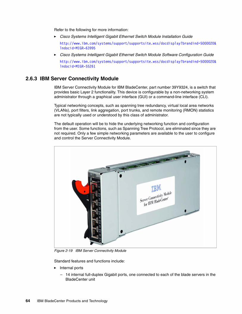
64 IBM BladeCenter Products and Technology
Refer to the following for more information:
� Cisco Systems Intelligent Gigabit Ethernet Switch Module Installation Guide
http://www.ibm.com/systems/support/supportsite.wss/docdisplay?brandind=5000020&lndocid=MIGR-63995
� Cisco Systems Intelligent Gigabit Ethernet Switch Module Software Configuration Guide
http://www.ibm.com/systems/support/supportsite.wss/docdisplay?brandind=5000020&lndocid=MIGR-55261
2.6.3 IBM Server Connectivity Module
IBM Server Connectivity Module for IBM BladeCenter, part number 39Y9324, is a switch that provides basic Layer 2 functionality. This device is configurable by a non-networking system administrator through a graphical user interface (GUI) or a command-line interface (CLI).
Typical networking concepts, such as spanning tree redundancy, virtual local area networks (VLANs), port filters, link aggregation, port trunks, and remote monitoring (RMON) statistics are not typically used or understood by this class of administrator.
The default operation will be to hide the underlying networking function and configuration from the user. Some functions, such as Spanning Tree Protocol, are eliminated since they are not required. Only a few simple networking parameters are available to the user to configure and control the Server Connectivity Module.
Figure 2-19 IBM Server Connectivity Module
Standard features and functions include:
� Internal ports
– 14 internal full-duplex Gigabit ports, one connected to each of the blade servers in the BladeCenter unit
Chapter 2. BladeCenter chassis and infrastructure configuration 65
– Two internal full-duplex 100 Mbps ports connected to the management module in slots 1 and 2
� External copper ports
– Six external ports are provided using standard Category 5 enhanced (5e) copper cable connectors
– 10/100/1000 Mbps interfaces: the external ports connect at 10 Mbps Full Duplex, 100 Mbps Full Duplex, or 1 Gbps Full Duplex
– Auto-negotiation capability
– Copper connection for making connections to a backbone, end stations, and servers
� Internal Switching
– Packet switching between the blade servers and management modules within the chassis to support Serial over LAN (SOL)
– Blade-server-to-blade-server switching is supported for those blade server ports that are assigned to a common group (up to six groups with dedicated uplinks)
� Configuration of the Server Connectivity Module is only through a connection to a management-module port and not through the external switch ports
� Support for tagged VLANs: the administrator can define VLAN identifiers (IDs) to match specific server application requirements
� Cisco EtherChannel compatible static link aggregation
� Management-module control that allows for external ports to be enabled or disabled
� Support for Ethernet jumbo frame formats (up to 9K bytes per frame)
� Two independent internal 100 Mbps FDX links connected to each of two management modules (jumbo frame support is not required on these links)
� Management-module I2C interface that provides VPD and register access
� Level 2 (L2) switching per current industry standards and practice
� “Non-networking” device appearance allows administration and installation of this device by the system manager rather than a network administrator
� Port aggregation (only for external ports)
� Port group failover (triggered by external ports)
� IEEE 802.3x Flow Control
� Internet group multicast protocol (IGMP) snooping
� IEEE 802.1Q support for SOL and optional user VLAN tagging of external ports
� RADIUS or TACACS+ user authentication
� Network cables
– 10BASE-T:
• UTP Category 3, 4, 5 (100 meters or 328.1 ft maximum)• 100-ohm STP (100 meters or 328.1 ft maximum)
– 100BASE-TX:
• UTP Category 5 (100 meters or 328.1 ft maximum)• EIA/TIA-568 100-ohm STP (100 meters or 328.1 ft maximum)
– 1000BASE-T:
• UTP Category 6 (standard for 1 GB devices)• UTP Category 5e (100 meters or 328.1 ft maximum)
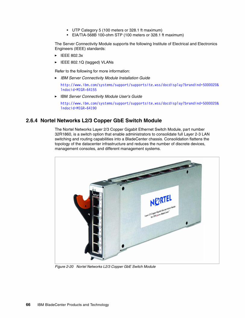
66 IBM BladeCenter Products and Technology
• UTP Category 5 (100 meters or 328.1 ft maximum)• EIA/TIA-568B 100-ohm STP (100 meters or 328.1 ft maximum)
The Server Connectivity Module supports the following Institute of Electrical and Electronics Engineers (IEEE) standards:
� IEEE 802.3x
� IEEE 802.1Q (tagged) VLANs
Refer to the following for more information:
� IBM Server Connectivity Module Installation Guide
http://www.ibm.com/systems/support/supportsite.wss/docdisplay?brandind=5000020&lndocid=MIGR-64155
� IBM Server Connectivity Module User's Guide
http://www.ibm.com/systems/support/supportsite.wss/docdisplay?brandind=5000020&lndocid=MIGR-64190
2.6.4 Nortel Networks L2/3 Copper GbE Switch Module
The Nortel Networks Layer 2/3 Copper Gigabit Ethernet Switch Module, part number 32R1860, is a switch option that enable administrators to consolidate full Layer 2-3 LAN switching and routing capabilities into a BladeCenter chassis. Consolidation flattens the topology of the datacenter infrastructure and reduces the number of discrete devices, management consoles, and different management systems.
Figure 2-20 Nortel Networks L2/3 Copper GbE Switch Module
Chapter 2. BladeCenter chassis and infrastructure configuration 67
Standard features and functions include:
� Internal ports
– 14 internal full-duplex Gigabit ports, one connected to each of the blade servers in the BladeCenter unit
– Two internal full-duplex 10/100 Mbps ports connected to the management module
� External ports: copper connection for making 10/100/1000 Mbps connections to a backbone, end stations, and servers
– Copper ports use six external 1000BASE-T RJ-45 connectors
– RS-232 serial port that provides an additional means to install software and configure the switch module
� Supported IEEE standards
– 10/100/1000 auto-negotiation– Static link aggregation (Ether channel compatible)– 802.3ad link aggregation– 802.1P (priority queues, eight per port)– 802.1P with IP DiffServ– 802.1P with Q priority (SMAC/DMAC, SIP/DIP, VLAN priorities)– 802.1Q (VLAN, 1024 maximum)– 802.1d spanning tree– 802.1s spanning tree/VLAN (16 spanning tree instances)– 802.1w rapid spanning tree– 802.1x port access control– Fast port forward– Fast uplink convergence– 802.3x flow control– IEEE 802.3 Nway auto-negotiation
� Layer 2 bridge/switch functions
– L2 port filters (static)– Port mirroring (any port to any port)– Jumbo frames (up to 9 Kb)– IGMP snooping (V1 and V2)– IGMP filtering– LAG distribution scheme (MAC SA/DA and IP SA/DA)– L2 multicast forwarding (hardware-based media speed)– L2 forwarding performance (media speed/non-blocking)
� Access control, security and management
– Radius/TACACS+– SSH– Multiple user IDs and passwords– User access control– Change tracking and remote logging– Scriptable command-line interface (CLI)– SNMP (V1 and V3)– HTTP browser graphical user interface (GUI)– Telnet interface for CLI– Automatic remote system log– Firmware image update (TFTP and FTP)– Layer 3 filtering– Layer 3 routing– Layer 3 protocols (RIP v1, RIP v2, OSPF v2 with ECMP/NSSA, BGP 4)
68 IBM BladeCenter Products and Technology
– DHCP/BOOTP– VRRP– Interchassis redundancy (L2 and L3)
� Special functions
– Serial over LAN (SOL)– L2 trunk failover– Bcast/Mcast storm control
� Network cables
– 10BASE-T:
• UTP Category 3, 4, 5 (100 meters maximum)• 100-ohm STP (100 meters maximum)
– 100BASE-TX:
• UTP Category 5 (100 meters maximum)• EIA/TIA-568 100-ohm STP (100 meters maximum)
– 1000BASE-T:
• UTP Category 6 (standard for 1 GB devices)• UTP Category 5e (100 meters maximum)• UTP Category 5 (100 meters maximum)• EIA/TIA-568B 100-ohm STP (100 meters maximum)
� RS-232 serial cable:
– 3 meter console cable DB-9 to USB connector (nonstandard use of USB connector) that comes with the GbE switch module
The GbE switch module supports the following IEEE standards:
� IEEE 802.1d Spanning Tree Protocol� IEEE 802.1P Tagged Packets� IEEE 802.1Q Tagged VLAN (frame tagging on all ports when VLANs are enabled)� IEEE 802.2 Logical Link Control� IEEE 802.3 10BASE-T Ethernet� IEEE 802.3u 100BASE-TX Fast Ethernet � IEEE 802.3x Full-duplex Flow Control
Refer to the following for more information:
� Nortel Networks Layer 2-3 GbE Switch Module Installation Guide
http://www.ibm.com/systems/support/supportsite.wss/docdisplay?brandind=5000020&lndocid=MIGR-58334
� Nortel Networks Layer 2-3 GbE Switch Module Application Guide
http://www.ibm.com/systems/support/supportsite.wss/docdisplay?brandind=5000020&lndocid=MIGR-58325
2.6.5 Nortel Networks L2/3 Fiber GbE Switch Module
The Nortel Networks Layer 2/3 Fiber Gigabit Ethernet Switch Module, part number 32R1861, is a switch option that enable administrators to consolidate full Layer 2-3 LAN switching and
Note: To make sure that the BladeCenter unit installation complies with electromagnetic compatibility (EMC) product regulations for intra-building lightning surges, you must use shielded LAN cables that are grounded at both ends.
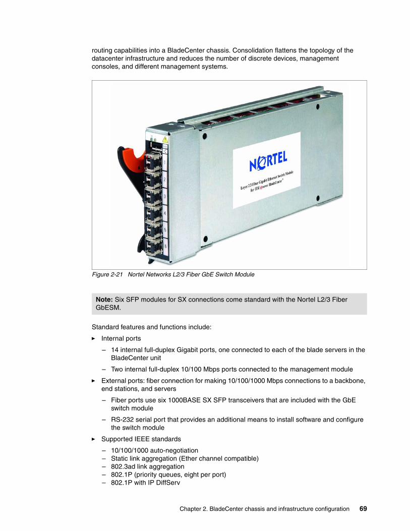
Chapter 2. BladeCenter chassis and infrastructure configuration 69
routing capabilities into a BladeCenter chassis. Consolidation flattens the topology of the datacenter infrastructure and reduces the number of discrete devices, management consoles, and different management systems.
Figure 2-21 Nortel Networks L2/3 Fiber GbE Switch Module
Standard features and functions include:
� Internal ports
– 14 internal full-duplex Gigabit ports, one connected to each of the blade servers in the BladeCenter unit
– Two internal full-duplex 10/100 Mbps ports connected to the management module
� External ports: fiber connection for making 10/100/1000 Mbps connections to a backbone, end stations, and servers
– Fiber ports use six 1000BASE SX SFP transceivers that are included with the GbE switch module
– RS-232 serial port that provides an additional means to install software and configure the switch module
� Supported IEEE standards
– 10/100/1000 auto-negotiation– Static link aggregation (Ether channel compatible)– 802.3ad link aggregation– 802.1P (priority queues, eight per port)– 802.1P with IP DiffServ
Note: Six SFP modules for SX connections come standard with the Nortel L2/3 Fiber GbESM.
70 IBM BladeCenter Products and Technology
– 802.1P with Q priority (SMAC/DMAC, SIP/DIP, VLAN priorities)– 802.1Q (VLAN, 1024 maximum)– 802.1d spanning tree– 802.1s spanning tree/VLAN (16 spanning tree instances)– 802.1w rapid spanning tree– 802.1x port access control– Fast port forward– Fast uplink convergence– 802.3x flow control– IEEE 802.3 Nway auto-negotiation
� Layer 2 bridge/switch functions
– L2 port filters (static)– Port mirroring (any port to any port)– Jumbo frames (up to 9 Kb)– IGMP snooping (V1 and V2)– IGMP filtering– LAG distribution scheme (MAC SA/DA and IP SA/DA)– L2 multicast forwarding (hardware-based media speed)– L2 forwarding performance (media speed/non-blocking)
� Access control, security and management
– Radius/TACACS+– SSH– Multiple user IDs and passwords– User access control– Change tracking and remote logging– Scriptable command-line interface (CLI)– SNMP (V1 and V3)– HTTP browser graphical user interface (GUI)– Telnet interface for CLI– Automatic remote system log– Firmware image update (TFTP and FTP)– Layer 3 filtering– Layer 3 routing– Layer 3 protocols (RIP v1, RIP v2, OSPF v2 with ECMP/NSSA, BGP 4)– DHCP/BOOTP– VRRP– Interchassis redundancy (L2 and L3)
� Special functions
– Serial over LAN (SOL)– L2 trunk failover– Bcast/Mcast storm control
� Network cables
– 1000BASESX: 850 Nm wavelength, multimode fiber, 50 µ or 62.5 µ (550 meters maximum), with LC duplex connector
� RS-232 serial cable: 3 meter console cable DB-9 to USB connector (nonstandard use of USB connector) that comes with the GbE switch module
The GbE switch module supports the following IEEE standards:
� IEEE 802.1d Spanning Tree Protocol
� IEEE 802.1P Tagged Packets
Chapter 2. BladeCenter chassis and infrastructure configuration 71
� IEEE 802.1Q Tagged VLAN (frame tagging on all ports when VLANs are enabled)
� IEEE 802.2 Logical Link Control
� IEEE 802.3 10BASE-T Ethernet
� IEEE 802.3u 100BASE-TX Fast Ethernet
� IEEE 802.3x Full-duplex Flow Control
� IEEE 802.3z
• 1000BASE-SX Gigabit Ethernet• Link Negotiation
Refer to the following for more information:
� Nortel Networks Layer 2-3 GbE Switch Module Installation Guide
http://www.ibm.com/systems/support/supportsite.wss/docdisplay?brandind=5000020&lndocid=MIGR-58334
� Nortel Networks Layer 2-3 GbE Switch Module Application Guide
http://www.ibm.com/systems/support/supportsite.wss/docdisplay?brandind=5000020&lndocid=MIGR-58325
2.6.6 Nortel Networks Layer 2-7 GbE Switch Module
The Nortel Networks Layer 2-7 GbE Switch, part number 32R1859, serves as a switching and routing fabric for the IBM BladeCenter server chassis. It also introduces Layer 4-7 functionality for application and server based load balancing, advanced filtering, content-aware intelligence, embedded security services, and persistence support.
Note: Fiber connections standard using a small-form-factor pluggable (SFP) transceiver that provides 1000BASE SX (850 nm wavelength) communication over multimode fiber cable (50µ or 62.5µ) at distances of up to 550 meters (1000BASE LX is not supported).
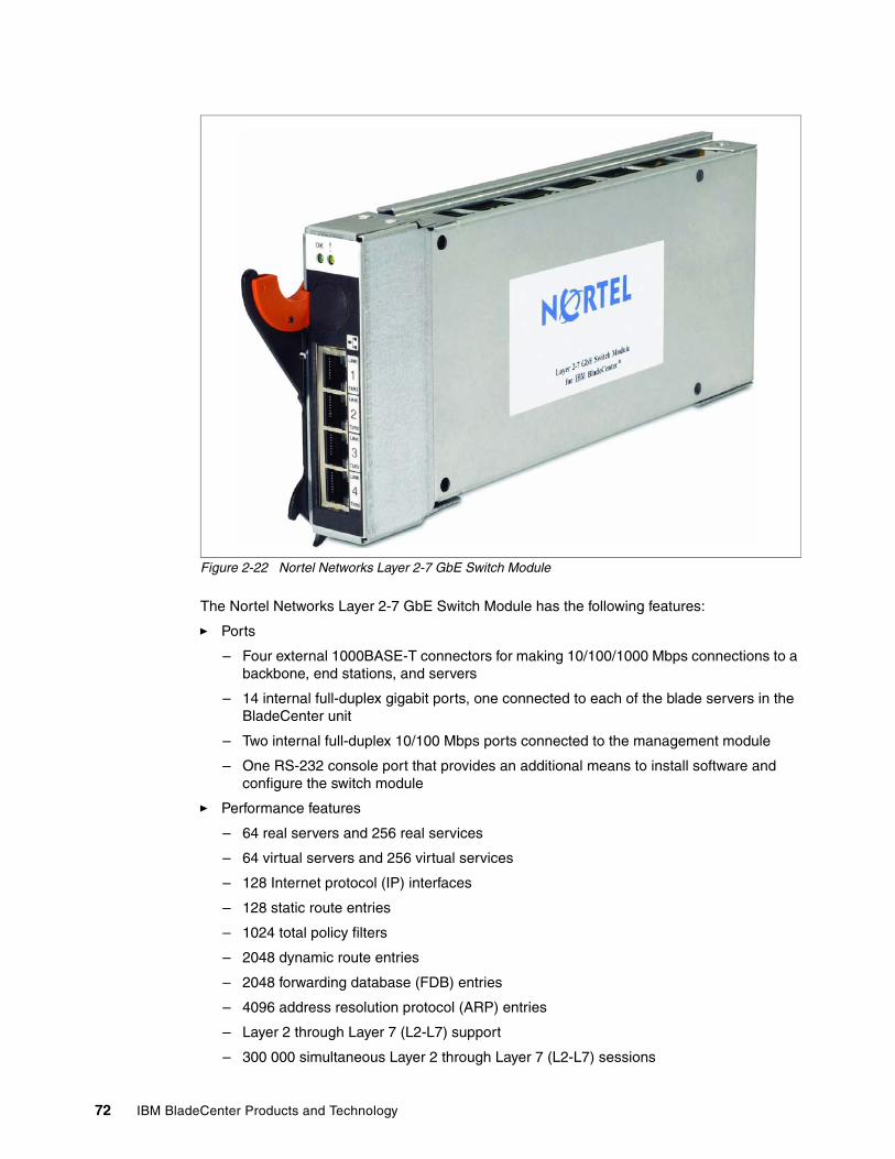
72 IBM BladeCenter Products and Technology
Figure 2-22 Nortel Networks Layer 2-7 GbE Switch Module
The Nortel Networks Layer 2-7 GbE Switch Module has the following features:
� Ports
– Four external 1000BASE-T connectors for making 10/100/1000 Mbps connections to a backbone, end stations, and servers
– 14 internal full-duplex gigabit ports, one connected to each of the blade servers in the BladeCenter unit
– Two internal full-duplex 10/100 Mbps ports connected to the management module
– One RS-232 console port that provides an additional means to install software and configure the switch module
� Performance features
– 64 real servers and 256 real services
– 64 virtual servers and 256 virtual services
– 128 Internet protocol (IP) interfaces
– 128 static route entries
– 1024 total policy filters
– 2048 dynamic route entries
– 2048 forwarding database (FDB) entries
– 4096 address resolution protocol (ARP) entries
– Layer 2 through Layer 7 (L2-L7) support
– 300 000 simultaneous Layer 2 through Layer 7 (L2-L7) sessions
Chapter 2. BladeCenter chassis and infrastructure configuration 73
– 802.1D spanning tree support; can be disabled on the entire switch or on a per-port basis
– Support for 16 multiple spanning tree groups
– 802.1Q tagged virtual local area network (VLAN) support
– Support for 128 VLANs
– Denial-of-Service protection
– Content-based load balancing
• Hypertext transfer protocol (HTTP)• Real time streaming protocol (RTSP)• Domain name system (DNS)
– Layer 4 load balancing
– HTTP cookie and secure sockets layer (SSL) session ID persistency
– Link aggregation with 802.3 support on four external ports for up to two trunk groups
– Media access control (MAC) address learning: automatic update, supports 2048 MAC addresses
– Packet forwarding rate:
• Full-wire speed for all connections• 148800 packets per second (pps) per port (for 100 Mbps)• 1488100 pps per port (for 1000 Mbps)
– Random-access memory (RAM) buffer: 128 MB
– Real server health checking
– High availability Modes
• Active - Standby• Active - Active• Hot Standby• Trunk Failover
– L2 trunk fail over with virtual router redundancy protocol (VRRP)
– Server processing on external ports
– Support for two network time protocol (NTP) time servers
– Support for terminal access controller access control system (TACACS+)
– Support for Internet group management protocol (IGMP) v1 and v2 snooping
– Routing Information Protocol version 1 (RIPv1), Border Gateway Protocol version 4 (BGPv4), and Open Shortest Path First version 2 (OSPFv2)
� Management
– Spanning Tree Protocol (STP) for creation of alternative backup paths and prevention of network loops
– Fast port forward
– Fast uplink convergence
– Simple Network Management Protocol (SNMP) version 1
– Fully configurable either in-band or out-of-band control through SNMP-based software
– Flash memory for software upgrades through Trivial File Transfer Protocol (TFTP) or Hypertext Transfer Protocol (HTTP) Web interface
– Browser-based management support
74 IBM BladeCenter Products and Technology
– TFTP support
– Bootstrap protocol (BOOTP) support
– Dynamic Host Configuration Protocol (DHCP) client support
– Password enabled
– Telnet remote-control console
� Network cables:
– 10BASE-T:
• UTP Category 3, 4, 5 (100 meters maximum)• 100-ohm STP (100 meters maximum)
– 100BASE-TX:
• UTP Category 5 (100 meters maximum)• EIA/TIA-568 100-ohm STP (100 meters maximum)
– 1000BASE-T:
• UTP Category 6 (standard for 1 GB devices)• UTP Category 5e (100 meters maximum)• UTP Category 5 (100 meters maximum)• EIA/TIA-568B 100-ohm STP (100 meters maximum)
� RS-232 serial cable: 3 meter console cable DB-9 to 8 pin DIN
The GbE switch module supports the following IEEE standards:
� IEEE 802.1d Spanning Tree Protocol� IEEE 802.1P Tagged Packets� IEEE 802.1Q Tagged VLAN (frame tagging on all ports when VLANs are enabled)� IEEE 802.2 Logical Link Control� IEEE 802.3 10BASE-T Ethernet� IEEE 802.3u 100BASE-TX Fast Ethernet� IEEE 802.3x Full-duplex Flow Control
Refer to the following for more information:
� Nortel Networks Layer 2-7 GbE Switch Module Installation Guide
http://www.ibm.com/systems/support/supportsite.wss/docdisplay?brandind=5000020&lndocid=MIGR-53065
� Nortel Networks Layer 2-7 GbE Switch Module Application Guide
http://www.ibm.com/systems/support/supportsite.wss/docdisplay?brandind=5000020&lndocid=MIGR-53098
2.6.7 Nortel 10 Gb Uplink Ethernet Switch Module
The Nortel 10 Gigabit Uplink Ethernet Switch Module, part number 32R1783, is a new switch option that enables administrators to provide full Layer 2-3 10 Gb LAN switching and routing capabilities in a BladeCenter chassis. Such consolidation flattens the topology of the data center infrastructure and reduces the number of discrete devices, management consoles and different management systems. The 10 Gigabit Uplink Ethernet Switch Module provides port
Note: RS-232 Serial Cable is not included. It should be purchased through service channel if required (FRU 26K6541).
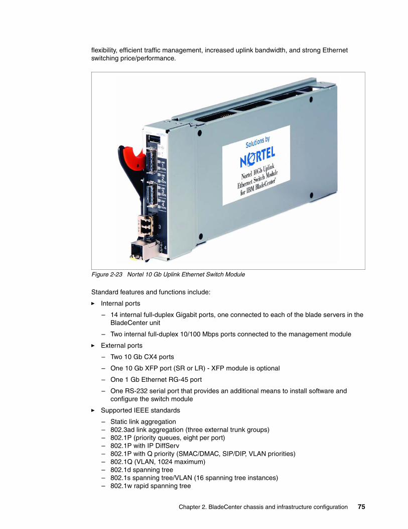
Chapter 2. BladeCenter chassis and infrastructure configuration 75
flexibility, efficient traffic management, increased uplink bandwidth, and strong Ethernet switching price/performance.
Figure 2-23 Nortel 10 Gb Uplink Ethernet Switch Module
Standard features and functions include:
� Internal ports
– 14 internal full-duplex Gigabit ports, one connected to each of the blade servers in the BladeCenter unit
– Two internal full-duplex 10/100 Mbps ports connected to the management module
� External ports
– Two 10 Gb CX4 ports
– One 10 Gb XFP port (SR or LR) - XFP module is optional
– One 1 Gb Ethernet RG-45 port
– One RS-232 serial port that provides an additional means to install software and configure the switch module
� Supported IEEE standards
– Static link aggregation– 802.3ad link aggregation (three external trunk groups)– 802.1P (priority queues, eight per port)– 802.1P with IP DiffServ– 802.1P with Q priority (SMAC/DMAC, SIP/DIP, VLAN priorities)– 802.1Q (VLAN, 1024 maximum)– 802.1d spanning tree– 802.1s spanning tree/VLAN (16 spanning tree instances)– 802.1w rapid spanning tree
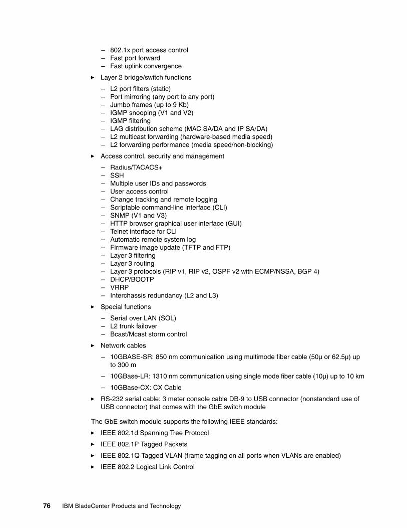
76 IBM BladeCenter Products and Technology
– 802.1x port access control– Fast port forward– Fast uplink convergence
� Layer 2 bridge/switch functions
– L2 port filters (static)– Port mirroring (any port to any port)– Jumbo frames (up to 9 Kb)– IGMP snooping (V1 and V2)– IGMP filtering– LAG distribution scheme (MAC SA/DA and IP SA/DA)– L2 multicast forwarding (hardware-based media speed)– L2 forwarding performance (media speed/non-blocking)
� Access control, security and management
– Radius/TACACS+– SSH– Multiple user IDs and passwords– User access control– Change tracking and remote logging– Scriptable command-line interface (CLI)– SNMP (V1 and V3)– HTTP browser graphical user interface (GUI)– Telnet interface for CLI– Automatic remote system log– Firmware image update (TFTP and FTP)– Layer 3 filtering– Layer 3 routing– Layer 3 protocols (RIP v1, RIP v2, OSPF v2 with ECMP/NSSA, BGP 4)– DHCP/BOOTP– VRRP– Interchassis redundancy (L2 and L3)
� Special functions
– Serial over LAN (SOL)– L2 trunk failover– Bcast/Mcast storm control
� Network cables
– 10GBASE-SR: 850 nm communication using multimode fiber cable (50µ or 62.5µ) up to 300 m
– 10GBase-LR: 1310 nm communication using single mode fiber cable (10µ) up to 10 km
– 10GBase-CX: CX Cable
� RS-232 serial cable: 3 meter console cable DB-9 to USB connector (nonstandard use of USB connector) that comes with the GbE switch module
The GbE switch module supports the following IEEE standards:
� IEEE 802.1d Spanning Tree Protocol
� IEEE 802.1P Tagged Packets
� IEEE 802.1Q Tagged VLAN (frame tagging on all ports when VLANs are enabled)
� IEEE 802.2 Logical Link Control
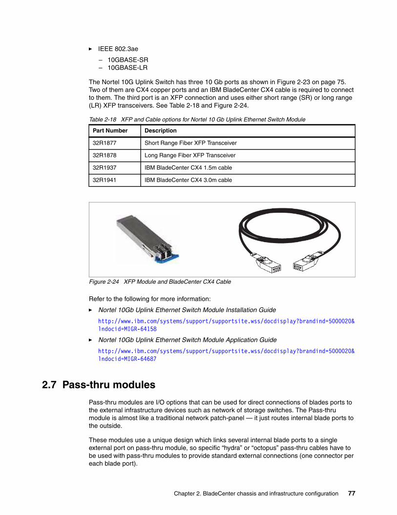
Chapter 2. BladeCenter chassis and infrastructure configuration 77
� IEEE 802.3ae
– 10GBASE-SR– 10GBASE-LR
The Nortel 10G Uplink Switch has three 10 Gb ports as shown in Figure 2-23 on page 75. Two of them are CX4 copper ports and an IBM BladeCenter CX4 cable is required to connect to them. The third port is an XFP connection and uses either short range (SR) or long range (LR) XFP transceivers. See Table 2-18 and Figure 2-24.
Table 2-18 XFP and Cable options for Nortel 10 Gb Uplink Ethernet Switch Module
Figure 2-24 XFP Module and BladeCenter CX4 Cable
Refer to the following for more information:
� Nortel 10Gb Uplink Ethernet Switch Module Installation Guide
http://www.ibm.com/systems/support/supportsite.wss/docdisplay?brandind=5000020&lndocid=MIGR-64158
� Nortel 10Gb Uplink Ethernet Switch Module Application Guide
http://www.ibm.com/systems/support/supportsite.wss/docdisplay?brandind=5000020&lndocid=MIGR-64687
2.7 Pass-thru modules
Pass-thru modules are I/O options that can be used for direct connections of blades ports to the external infrastructure devices such as network of storage switches. The Pass-thru module is almost like a traditional network patch-panel — it just routes internal blade ports to the outside.
These modules use a unique design which links several internal blade ports to a single external port on pass-thru module, so specific “hydra” or “octopus” pass-thru cables have to be used with pass-thru modules to provide standard external connections (one connector per each blade port).
Part Number Description
32R1877 Short Range Fiber XFP Transceiver
32R1878 Long Range Fiber XFP Transceiver
32R1937 IBM BladeCenter CX4 1.5m cable
32R1941 IBM BladeCenter CX4 3.0m cable
78 IBM BladeCenter Products and Technology
There are two types of pass-thru modules: Copper Pass-thru Module (CPM) and Optical Pass-thru module (OPM). Both of them are capable of carrying Ethernet signals but only OPM can be used for Fibre Channel signals (see Table 2-13 on page 50 for more information).
2.7.1 IBM BladeCenter Copper Pass-thru Module
The IBM BladeCenter Copper Pass-thru Module, part number 39Y9320, is one of the types of I/O modules that can be installed in a BladeCenter unit. The copper pass-thru module provides an unconfigured network connection that enables the blade servers in the BladeCenter unit to connect to an existing network infrastructure. No configuration of the copper pass-thru module is required.
For supported I/O bays and technologies, refer to Table 2-13 on page 50.
Figure 2-25 IBM BladeCenter Copper pass-thru Module and cable
The features include:
� Ports
– Three external copper ports for making connections to network infrastructure, and each port provides connections for up to five bi-directional copper channels
– 14 internal bi-directional ports, connected through the copper pass-thru cables to each of the blade servers
� Status and error LEDs
– Information LEDs on the front panel indicate I/O module port status and errors
� Cables:
– Up to three copper pass-thru module cables can be connected to the copper pass-thru module (one copper pass-thru module cable is provided)
– The copper pass-thru module cables are terminated with industry-standard bi-directional connectors
Table 2-19 on page 79 shows CPM-related options:
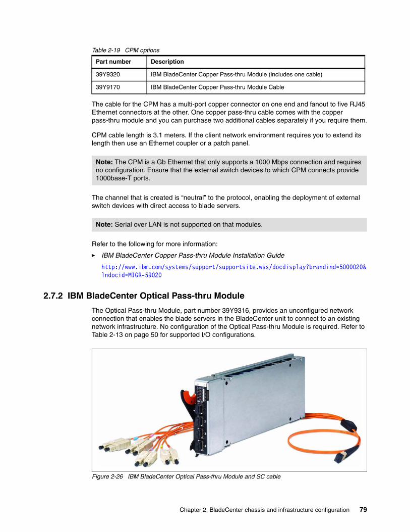
Chapter 2. BladeCenter chassis and infrastructure configuration 79
Table 2-19 CPM options
The cable for the CPM has a multi-port copper connector on one end and fanout to five RJ45 Ethernet connectors at the other. One copper pass-thru cable comes with the copper pass-thru module and you can purchase two additional cables separately if you require them.
CPM cable length is 3.1 meters. If the client network environment requires you to extend its length then use an Ethernet coupler or a patch panel.
The channel that is created is “neutral” to the protocol, enabling the deployment of external switch devices with direct access to blade servers.
Refer to the following for more information:
� IBM BladeCenter Copper Pass-thru Module Installation Guide
http://www.ibm.com/systems/support/supportsite.wss/docdisplay?brandind=5000020&lndocid=MIGR-59020
2.7.2 IBM BladeCenter Optical Pass-thru Module
The Optical Pass-thru Module, part number 39Y9316, provides an unconfigured network connection that enables the blade servers in the BladeCenter unit to connect to an existing network infrastructure. No configuration of the Optical Pass-thru Module is required. Refer to Table 2-13 on page 50 for supported I/O configurations.
Figure 2-26 IBM BladeCenter Optical Pass-thru Module and SC cable
Part number Description
39Y9320 IBM BladeCenter Copper Pass-thru Module (includes one cable)
39Y9170 IBM BladeCenter Copper Pass-thru Module Cable
Note: The CPM is a Gb Ethernet that only supports a 1000 Mbps connection and requires no configuration. Ensure that the external switch devices to which CPM connects provide 1000base-T ports.
Note: Serial over LAN is not supported on that modules.
80 IBM BladeCenter Products and Technology
The IBM BladeCenter Optical Pass-thru Module features include:
� Ports
– Four external optical ports for making connections to network infrastructure, and each port provides connections for up to four bi-directional optical channels
– 14 internal full-duplex ports, one connected to each of the blade servers
� Status and failure LEDs
– Information LEDs on the front panel indicate I/O module and port status and faults
� Cables
– Up to four optical pass-thru module cables (not included) can be connected to the Optical Pass-thru Module
– The optical pass-thru module cable are terminated with industry-standard duplex connectors
Table 2-20 shows OPM-related options:
Table 2-20 OPM options
The optical pass-thru cable does not come with the OPM and you must purchase it as a separate item. The cable provides four connections between the optical pass-thru module and an external Ethernet or Fibre environment.
The Optical Pass-thru Module Cable is 1.5 meters in length, and optical couplers are supplied with the cables so that their length can be extended to 150 meters.
The Multi-Port Optical connector on the optical pass-thru cable is attached to the OPM fiber optic port and the other end of the cable has 4 SC or LC duplex optical connectors, that are attached to networking device beyond the OPM.
Refer to the following for more information:
� IBM BladeCenter Optical Pass-thru Module Installation Guide
http://www.ibm.com/systems/support/supportsite.wss/docdisplay?brandind=5000020&lndocid=MIGR-52864
Option number Description
39Y9316 IBM BladeCenter Optical Pass-thru Module (does not include any cables)
39Y9171 IBM BladeCenter Optical Pass-thru Module SC Cable
39Y9172 IBM BladeCenter Optical Pass-thru Module LC Cable
Note:
� Serial over LAN is not supported on this module.
� OPM supports speeds of up to 2 Gb Fibre Channel. If you will use external 4 Gb FC switches and internal 4 Gb FC expansion cards together with OPM the FC fabric will operate at 2 Gb.
Chapter 2. BladeCenter chassis and infrastructure configuration 81
2.8 Fibre Channel switch modules
This section discusses different SAN storage options available for IBM BladeCenter. For information related to storage infrastructure planning and integration see Chapter 5, “Storage integration” on page 175.
Table 2-21 shows the current Fibre Channel switch modules. All FC switch modules are supported only in I/O module bays 3 and 4 (see Table 2-13 on page 50).
Table 2-21 Fibre Channel switch modules
2.8.1 Brocade 20-port 4 Gb Fibre Channel Switch Module
The Brocade 10-port and 20-port 4 Gb SAN switch module, part number 32R1812, provides the integration of the Brocade fabric into the BladeCenter architecture. These SAN fabric switches deliver the advanced Brocade functions, performance, manageability, scalability and security required by the most demanding storage area networks. Integration of SAN switching capabilities reduce complexity and increase SAN manageability.
Part number
Description Number of external ports
Port interface bandwidth
Page
32R1812 Brocade 20-port 4 Gb Fibre Channel Switch Module 6 4 Gbps 81
32R1813 Brocade 10-port 4 Gb Fibre Channel Switch Modulea
a. Only 3 external and first 7 internal ports are activated on that switches. An optional upgrade to 20-port is available.
6 4 Gbps 84
26R0881 QLogic 20-port 4 Gb Fibre Channel Switch Module 6 4 Gbps 84
32R1904 QLogic 10-port 4 Gb Fibre Channel Switch Modulea 6 4 Gbps 86
32R1833 McDATA 20-port 4 Gb Fibre Channel Switch Module 6 4 Gbps 86
32R1905 McDATA 10-port 4 Gb Fibre Channel Switch Modulea 6 4 Gbps 88
691810X IBM System Storage™ SAN10Q 4 GB 10-Port FC Switch 10 4 Gbps 89
Note: When using the 4 Gb switch module with the BladeCenter T unit, the internal ports operate at 2 Gbps and the external ports operate at 4 Gbps.
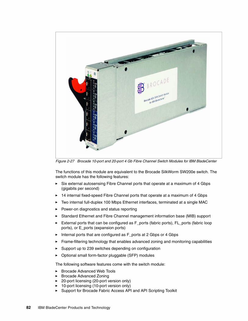
82 IBM BladeCenter Products and Technology
Figure 2-27 Brocade 10-port and 20-port 4 Gb Fibre Channel Switch Modules for IBM BladeCenter
The functions of this module are equivalent to the Brocade SilkWorm SW200e switch. The switch module has the following features:
� Six external autosensing Fibre Channel ports that operate at a maximum of 4 Gbps (gigabits per second)
� 14 internal fixed-speed Fibre Channel ports that operate at a maximum of 4 Gbps
� Two internal full-duplex 100 Mbps Ethernet interfaces, terminated at a single MAC
� Power-on diagnostics and status reporting
� Standard Ethernet and Fibre Channel management information base (MIB) support
� External ports that can be configured as F_ports (fabric ports), FL_ports (fabric loop ports), or E_ports (expansion ports)
� Internal ports that are configured as F_ports at 2 Gbps or 4 Gbps
� Frame-filtering technology that enables advanced zoning and monitoring capabilities
� Support up to 239 switches depending on configuration
� Optional small form-factor pluggable (SFP) modules
The following software features come with the switch module:
� Brocade Advanced Web Tools� Brocade Advanced Zoning� 20-port licensing (20-port version only)� 10-port licensing (10-port version only)� Support for Brocade Fabric Access API and API Scripting Toolkit
Chapter 2. BladeCenter chassis and infrastructure configuration 83
The switch supports the following fabric management (all management connections are going through management module):
� Management methods:
– Web interface through Advanced Web Tools– Command-line interface (CLI) through Telnet program– Application program interface (API)
� Brocade Fabric Manager Advanced Feature Options: provides Java™-based application program to help manage the storage area network (SAN) fabric
� Management information base (MIB)
� Switch simple network management protocol (SNMP) agent: enables a network management workstation to receive configuration values, traffic information, and Fibre Channel failure data through SNMP and the Ethernet interface
Table 2-22 Supported SFPs for Brocade 4 Gb FC Switch Module
Table 2-23 lists optional features available for these switches.
Table 2-23 Optional software features for Brocade 4 Gb FC Switch Module
Refer to the following for additional information:
� Brocade 4 Gb SAN Switch Module Installation Guide
http://www.ibm.com/systems/support/supportsite.wss/docdisplay?brandind=5000020&lndocid=MIGR-62707
Note: The switch comes without SFP modules, and they have to be ordered. See Table 2-22 for Part Numbers supported
Part number Description
22R4897 4 Gbps SW SFP Transceiver 4 Pack
22R4902 4 Gbps SW SFP Transceiver
19K1271 2 Gb Fibre Channel Short Wave SFP Module
22R0483 2 Gb Fibre Channel Short Wave SFP 4 pack
19K1272 2 Gb Fibre Channel Long Wave SFP Module
22R0484 2 Gb Fibre Channel Long Wave SFP 4 pack
Part Number Description
26K5607 Brocade ISL Trunking for IBM eServer™ BladeCenter
26K5612 Brocade Advanced Performance Monitoring for IBM eServer BladeCenter
26K5613 Brocade Extended Fabrics for IBM eServer BladeCenter
32R1919 Brocade Fabric Manager v5.x for IBM BladeCenter
26K5617 Brocade Advanced Security (Secure OS) for IBM eServer BladeCenter
32R1855 Brocade 4 Gb Fabric Watch for IBM BladeCenter
32R1822 Brocade 4 Gb 10-Port Upgrade for IBM BladeCentera
a. Available for 10-port switch only.
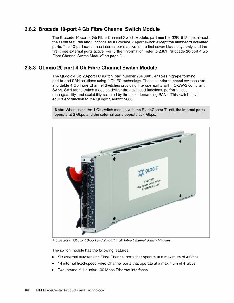
84 IBM BladeCenter Products and Technology
2.8.2 Brocade 10-port 4 Gb Fibre Channel Switch Module
The Brocade 10-port 4 Gb Fibre Channel Switch Module, part number 32R1813, has almost the same features and functions as a Brocade 20-port switch except the number of activated ports. The 10-port switch has internal ports active to the first seven blade bays only, and the first three external ports active. For further information, refer to 2.8.1, “Brocade 20-port 4 Gb Fibre Channel Switch Module” on page 81.
2.8.3 QLogic 20-port 4 Gb Fibre Channel Switch Module
The QLogic 4 Gb 20-port FC switch, part number 26R0881, enables high-performing end-to-end SAN solutions using 4 Gb FC technology. These standards-based switches are affordable 4 Gb Fibre Channel Switches providing interoperability with FC-SW-2 compliant SANs. SAN fabric switch modules deliver the advanced functions, performance, manageability, and scalability required by the most demanding SANs. This switch have equivalent function to the QLogic SANbox 5600.
Figure 2-28 QLogic 10-port and 20-port 4 Gb Fibre Channel Switch Modules
The switch module has the following features:
� Six external autosensing Fibre Channel ports that operate at a maximum of 4 Gbps
� 14 internal fixed-speed Fibre Channel ports that operate at a maximum of 4 Gbps
� Two internal full-duplex 100 Mbps Ethernet interfaces
Note: When using the 4 Gb switch module with the BladeCenter T unit, the internal ports operate at 2 Gbps and the external ports operate at 4 Gbps.
Chapter 2. BladeCenter chassis and infrastructure configuration 85
� External ports that can be configured as F_ports (fabric ports), FL_ports (fabric loop ports), or E_ports (expansion ports)
� Internal ports that are configured as F_ports at 2 Gbps or 4 Gbps
� Power-on diagnostics and status reporting
� Fabric security for controlling management access
� Support for Non-Disruptive Code Load Activation (NDCLA)
� Simple name server implementation
� Registered State Change Notification (RSCN)
� Support for standards based FC-SW2 interoperability
� Error detection
� Frame bundling
� Configurable Fabric Address Notification (FAN)
� Support up to 239 switches depending on configuration
� Optional small form-factor pluggable (SFP) modules
The following software features come with the switch module:
� SANBrowser Web interface
� 20-port licensing (20-port version only)
� 10-port licensing (10-port version only)
The switch supports the following fabric management (all management connections are going through management module):
� Management methods:
– Web interface through SANBrowser– Command-line interface (CLI) through Telnet program
� SANsurfer application
� Switch simple network management protocol (SNMP) agent: enables a network management workstation to receive configuration values, traffic information, and Fibre Channel failure data through SNMP and the Ethernet interface
Table 2-24 Supported SFPs for QLogic 4 Gb FC Switch Module
Note: The switch comes without SFP modules, and they have to be ordered. See Table 2-24 for Part Numbers supported
Part Number Description
22R4897 4 Gbps SW SFP Transceiver 4 Pack
22R4902 4 Gbps SW SFP Transceiver
19K1271 2 Gb Fibre Channel Short Wave SFP Module
22R0483 2 Gb Fibre Channel Short Wave SFP 4 pack
19K1272 2 Gb Fibre Channel Long Wave SFP Module
22R0484 2 Gb Fibre Channel Long Wave SFP 4 pack
86 IBM BladeCenter Products and Technology
Table 2-25 lists optional features available for that switches.
Table 2-25 Optional software features for QLogic 4 Gb FC Switch Module
Refer to the following for more information:
� QLogic 4 Gb Fibre Channel Switch Module Installation Guide
http://www.ibm.com/systems/support/supportsite.wss/docdisplay?brandind=5000020&lndocid=MIGR-58197
2.8.4 QLogic 10-port 4 Gb Fibre Channel Switch Module
The QLogic 10-port 4 Gb Fibre Channel Switch Module, part number 32R1904, has almost the same features and functions as a QLogic 20-port switch except the number of activated ports. The 10-port switch has internal ports active to the first seven blade bays only, and the first three external ports active.
For further information, refer to 2.8.3, “QLogic 20-port 4 Gb Fibre Channel Switch Module” on page 84
2.8.5 McDATA 20-port 4 Gb Fibre Channel Switch Module
The McDATA 20 port FC switch, part 32R1833, enables high-performing end-to-end SAN solutions using 4 Gb FC technology. The McDATA switch module allows seamless integration of BladeCenter into McDATA fabrics. Easy to deploy, these switches provide centralized McDATA management in McDATA fabrics and deliver McDATA-capable fabric services. With the industry-leading network and storage flexibility, this offering delivers McDATA functions, performance, manageability, scalability, and security required by the most demanding networks.
Part Number Description
32R1795 McDATA Mode Firmware Upgrade for IBM BladeCenter QLogic Switch Modules
32R1797 McDATA SANtegrity Activation for IBM BladeCenter
32R1912 QLogic/McDATA 10-Port Upgrade for IBM BladeCentera
a. Available for 10-port switch only.
Note: When using the 4 Gb switch module with the BladeCenter T unit, the internal ports operate at 2 Gbps and the external ports operate at 4 Gbps.
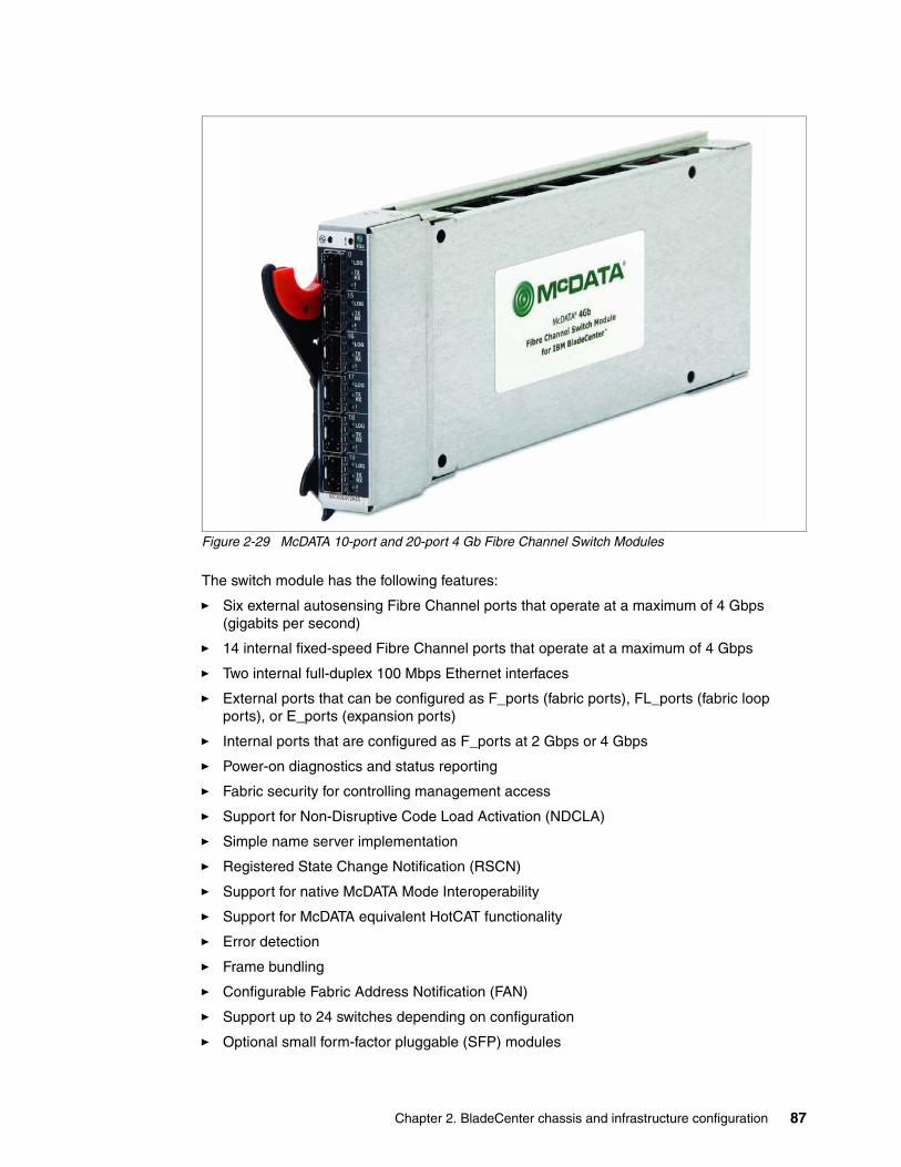
Chapter 2. BladeCenter chassis and infrastructure configuration 87
Figure 2-29 McDATA 10-port and 20-port 4 Gb Fibre Channel Switch Modules
The switch module has the following features:
� Six external autosensing Fibre Channel ports that operate at a maximum of 4 Gbps (gigabits per second)
� 14 internal fixed-speed Fibre Channel ports that operate at a maximum of 4 Gbps
� Two internal full-duplex 100 Mbps Ethernet interfaces
� External ports that can be configured as F_ports (fabric ports), FL_ports (fabric loop ports), or E_ports (expansion ports)
� Internal ports that are configured as F_ports at 2 Gbps or 4 Gbps
� Power-on diagnostics and status reporting
� Fabric security for controlling management access
� Support for Non-Disruptive Code Load Activation (NDCLA)
� Simple name server implementation
� Registered State Change Notification (RSCN)
� Support for native McDATA Mode Interoperability
� Support for McDATA equivalent HotCAT functionality
� Error detection
� Frame bundling
� Configurable Fabric Address Notification (FAN)
� Support up to 24 switches depending on configuration
� Optional small form-factor pluggable (SFP) modules
88 IBM BladeCenter Products and Technology
The following software features come with the switch module:
� McDATA SANBrowser Web interface
� 20-port licensing (20-port version only)
� 10-port licensing (10-port version only)
The switch supports the following fabric management (all management connections are going through management module):
� Management methods:
– Web interface through McDATA SANBrowser
– Command-line interface (CLI) through Telnet program
� SANsurfer application
� Switch simple network management protocol (SNMP) agent: enables a network management workstation to receive configuration values, traffic information, and Fibre Channel failure data through SNMP and the Ethernet interface
Table 2-26 Supported SFPs for McDATA 4 Gb FC Switch Module
Table 2-27 lists optional features available for that switches.
Table 2-27 Optional software features for McDATA 4 Gb FC Switch Module
2.8.6 McDATA 10-port 4 Gb Fibre Channel Switch Module
The McDATA 10-port 4 Gb Fibre Channel Switch Module, part number 32R1905, has almost the same features and functions as a McDATA 20-port switch except the number of activated ports. The 10-port switch has internal ports active to the first seven blade bays only, and the first three external ports active.
Note: The switch comes without SFP modules, and they have to be ordered. See Table 2-26 for Part Numbers supported
Part Number Description
22R4897 4 Gbps SW SFP Transceiver 4 Pack
22R4902 4 Gbps SW SFP Transceiver
19K1271 2 Gb Fibre Channel Short Wave SFP Module
22R0483 2 Gb Fibre Channel Short Wave SFP 4 pack
19K1272 2 Gb Fibre Channel Long Wave SFP Module
22R0484 2 Gb Fibre Channel Long Wave SFP 4 pack
Part Number Description
32R1797 McDATA SANtegrity Activation for IBM BladeCenter
32R1799 McData EFCM Element Manager for IBM BladeCenter
32R1912 QLogic/McDATA 10-Port Upgrade for IBM BladeCentera
a. Available for 10-port switch only.
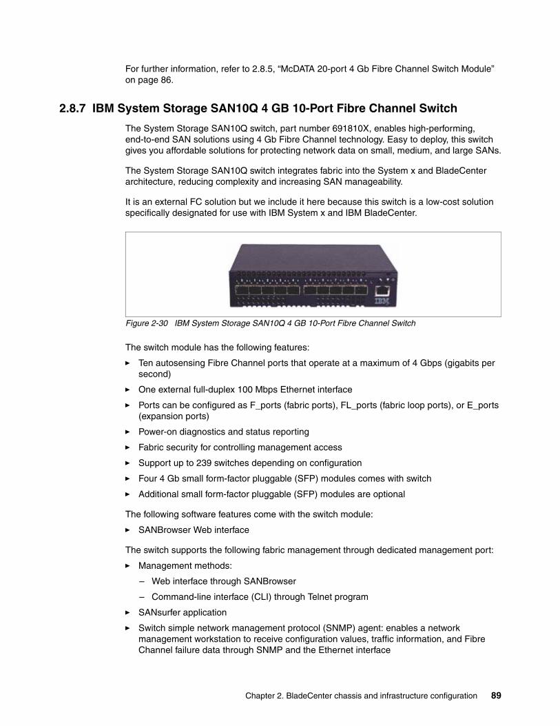
Chapter 2. BladeCenter chassis and infrastructure configuration 89
For further information, refer to 2.8.5, “McDATA 20-port 4 Gb Fibre Channel Switch Module” on page 86.
2.8.7 IBM System Storage SAN10Q 4 GB 10-Port Fibre Channel Switch
The System Storage SAN10Q switch, part number 691810X, enables high-performing, end-to-end SAN solutions using 4 Gb Fibre Channel technology. Easy to deploy, this switch gives you affordable solutions for protecting network data on small, medium, and large SANs.
The System Storage SAN10Q switch integrates fabric into the System x and BladeCenter architecture, reducing complexity and increasing SAN manageability.
It is an external FC solution but we include it here because this switch is a low-cost solution specifically designated for use with IBM System x and IBM BladeCenter.
Figure 2-30 IBM System Storage SAN10Q 4 GB 10-Port Fibre Channel Switch
The switch module has the following features:
� Ten autosensing Fibre Channel ports that operate at a maximum of 4 Gbps (gigabits per second)
� One external full-duplex 100 Mbps Ethernet interface
� Ports can be configured as F_ports (fabric ports), FL_ports (fabric loop ports), or E_ports (expansion ports)
� Power-on diagnostics and status reporting
� Fabric security for controlling management access
� Support up to 239 switches depending on configuration
� Four 4 Gb small form-factor pluggable (SFP) modules comes with switch
� Additional small form-factor pluggable (SFP) modules are optional
The following software features come with the switch module:
� SANBrowser Web interface
The switch supports the following fabric management through dedicated management port:
� Management methods:
– Web interface through SANBrowser
– Command-line interface (CLI) through Telnet program
� SANsurfer application
� Switch simple network management protocol (SNMP) agent: enables a network management workstation to receive configuration values, traffic information, and Fibre Channel failure data through SNMP and the Ethernet interface
90 IBM BladeCenter Products and Technology
Table 2-28 Supported SFPs and other options for SAN10Q 4 Gb FC Switch
Refer to the following for additional information:
� IBM System Storage SAN10Q 4 Gbps 10-Port Fibre Channel Switch Installation Guide
http://www.ibm.com/support/docview.wss?uid=ssg1S7001476
� IBM System Storage SAN10Q 4 Gbps 10-Port Fibre Channel Switch Manager User Guide
http://www.ibm.com/support/docview.wss?uid=ssg1S7001475
2.9 InfiniBand switch modules
InfiniBand is an advanced I/O technology that provides the following features:
� Scales-out data centers by interconnecting blades and chassis together with InfiniBand as the interconnect
� Leverages high bandwidth and low latency characteristics of the InfiniBand standard with Remote Direct Memory Access (RDMA)
� Enables consolidation of LAN and SAN connectivity for an entire data cluster to a centralized location
� Virtualizes and shares I/O and storage across an entire BladeCenter or collection of BladeCenter chassis for cost savings and high availability
There is one InfiniBand switch module available for BladeCenter (see Table 2-29).
Table 2-29 InfiniBand switch modules for IBM BladeCenter
See Table 2-13 on page 50 (BladeCenter), Table 2-14 on page 51 (BladeCenter H), and Table 2-15 on page 52 (BladeCenter T) for list of supported configurations for the Topspin InfiniBand Switch Module (IBSM).
2.9.1 Cisco Systems InfiniBand Switch Module
The Cisco Systems InfiniBand Switch Module for IBM BladeCenter (also known as the Topspin InfiniBand Switch Module), part number 32R1900, adds InfiniBand (IB) switching capability to hosts in your IBM BladeCenter chassis.
Note: This switch module replaces Topspin InfiniBand Switch Module, part number 26K6454.
Note: The switch comes with four 4 Gb SFP modules. See Table 2-28 for part numbers of additional SFPs supported.
Part Number Description
39R6475 4 Gbps SW SFP Transceiver
39R6523 IBM SAN10Q Rack Kita
a. Two switch units can be mounted in a 1U rack space with this option
Part Number Description
32R1900 Topspin IB Switch Module for IBM BladeCenter
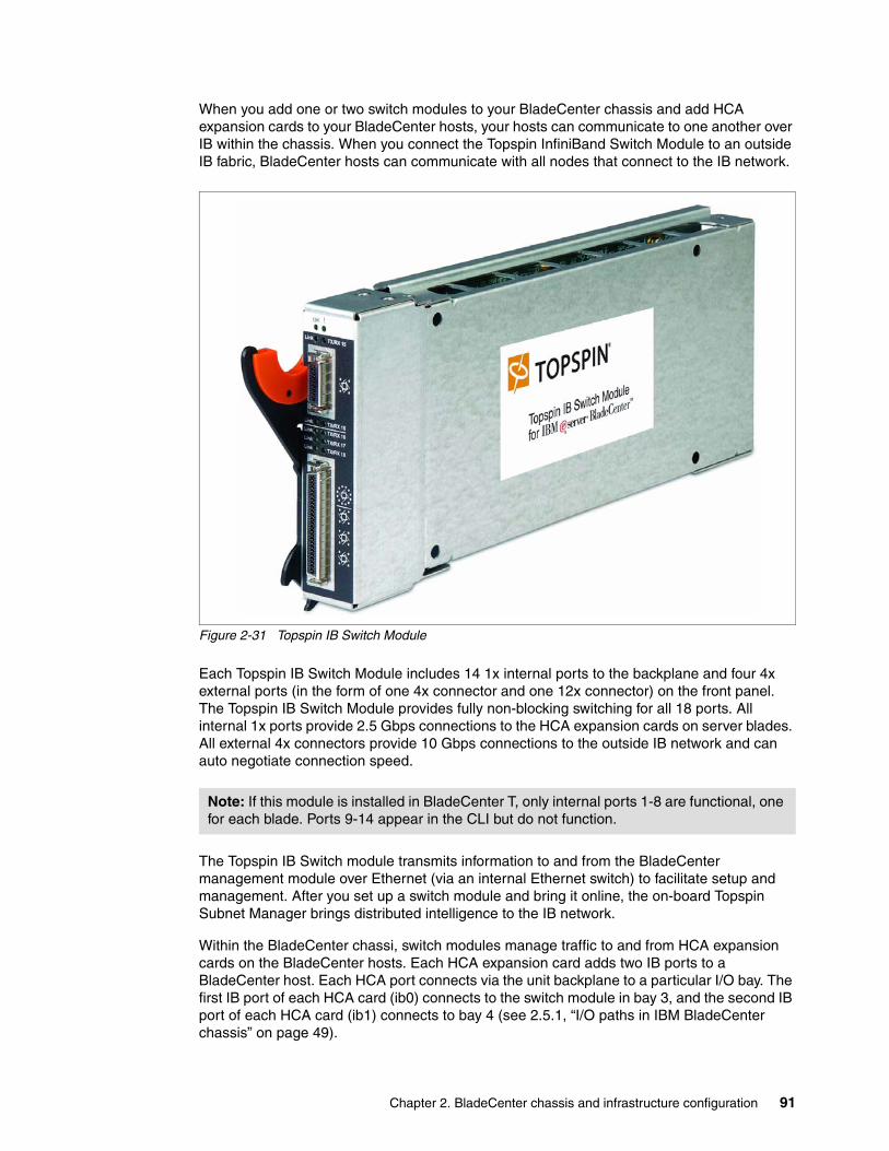
Chapter 2. BladeCenter chassis and infrastructure configuration 91
When you add one or two switch modules to your BladeCenter chassis and add HCA expansion cards to your BladeCenter hosts, your hosts can communicate to one another over IB within the chassis. When you connect the Topspin InfiniBand Switch Module to an outside IB fabric, BladeCenter hosts can communicate with all nodes that connect to the IB network.
Figure 2-31 Topspin IB Switch Module
Each Topspin IB Switch Module includes 14 1x internal ports to the backplane and four 4x external ports (in the form of one 4x connector and one 12x connector) on the front panel. The Topspin IB Switch Module provides fully non-blocking switching for all 18 ports. All internal 1x ports provide 2.5 Gbps connections to the HCA expansion cards on server blades. All external 4x connectors provide 10 Gbps connections to the outside IB network and can auto negotiate connection speed.
The Topspin IB Switch module transmits information to and from the BladeCenter management module over Ethernet (via an internal Ethernet switch) to facilitate setup and management. After you set up a switch module and bring it online, the on-board Topspin Subnet Manager brings distributed intelligence to the IB network.
Within the BladeCenter chassi, switch modules manage traffic to and from HCA expansion cards on the BladeCenter hosts. Each HCA expansion card adds two IB ports to a BladeCenter host. Each HCA port connects via the unit backplane to a particular I/O bay. The first IB port of each HCA card (ib0) connects to the switch module in bay 3, and the second IB port of each HCA card (ib1) connects to bay 4 (see 2.5.1, “I/O paths in IBM BladeCenter chassis” on page 49).
Note: If this module is installed in BladeCenter T, only internal ports 1-8 are functional, one for each blade. Ports 9-14 appear in the CLI but do not function.
92 IBM BladeCenter Products and Technology
You can manage your Topspin IB Switch Module with any of the following interfaces:
� Simple Network Management Protocol (SNMP) versions 1, 2, and 3 with Topspin’s Management Information Base (MIBs)
� TopspinOS command line interface (CLI)
� Chassis Manager Web-based GUI
� Element Manager Java-based GUI
� APIs (via SNMP)
Table 2-30 shows Topspin InfiniBand switch module-related options:
Table 2-30 Topspin InfiniBand Switch Module options
Refer to the following for additional information:
� Topspin InfiniBand Switch Module for IBM BladeCenter User Guide
http://www.ibm.com/systems/support/supportsite.wss/docdisplay?brandind=5000020&lndocid=MIGR-60200
2.10 High speed switch modules
High speed switch modules supports transfer speeds of up to 10Gbit, such as 4X InfiniBand or 10Gb Ethernet. Currently, there is only one high speed switch module (see Table 2-31).
Table 2-31 High speed switch modules for IBM BladeCenter H
See Table 2-14 on page 51 for list of supported configurations for Cisco 4X InfiniBand switch module (HSIB) in IBM BladeCenter H.
2.10.1 Cisco Systems 4X IB Switch Module for IBM BladeCenter
The Cisco 4x InfiniBand Switch module for IBM BladeCenter, part number 32R1756, adds InfiniBand (IB) switching capability to hosts in your IBM BladeCenter H chassis. When you add one or two switch modules to your BladeCenter H chassis and add HCA expansion cards to your blade servers, your servers can communicate to one another over IB within the chassis. When you connect the switch module to an outside IB fabric, servers can communicate with all nodes that connect to the IB network.
This switch for IBM BladeCenter H delivers low-latency, high-bandwidth connectivity (up to 240 Gbps full duplex) between InfiniBand connected internal BladeCenter server blades, additional BladeCenter H chassis, stand-alone servers, and external gateways for connectivity to Ethernet LANs and Fibre Channel SANs.
Part number Description
26R0816 InfiniBand 3 meter 12x to (3) 4x Cable for IBM BladeCenter
26R0849 InfiniBand 8 meter 12x to (3) 4x Cable for IBM BladeCenter
26R0813 InfiniBand 3 meter 4x Cable for IBM BladeCenter
26R0847 InfiniBand 8 meter 4x Cable for IBM BladeCenter
Part Number Description
32R1756 Cisco Systems 4X InfiniBand Switch Module for IBM BladeCenter
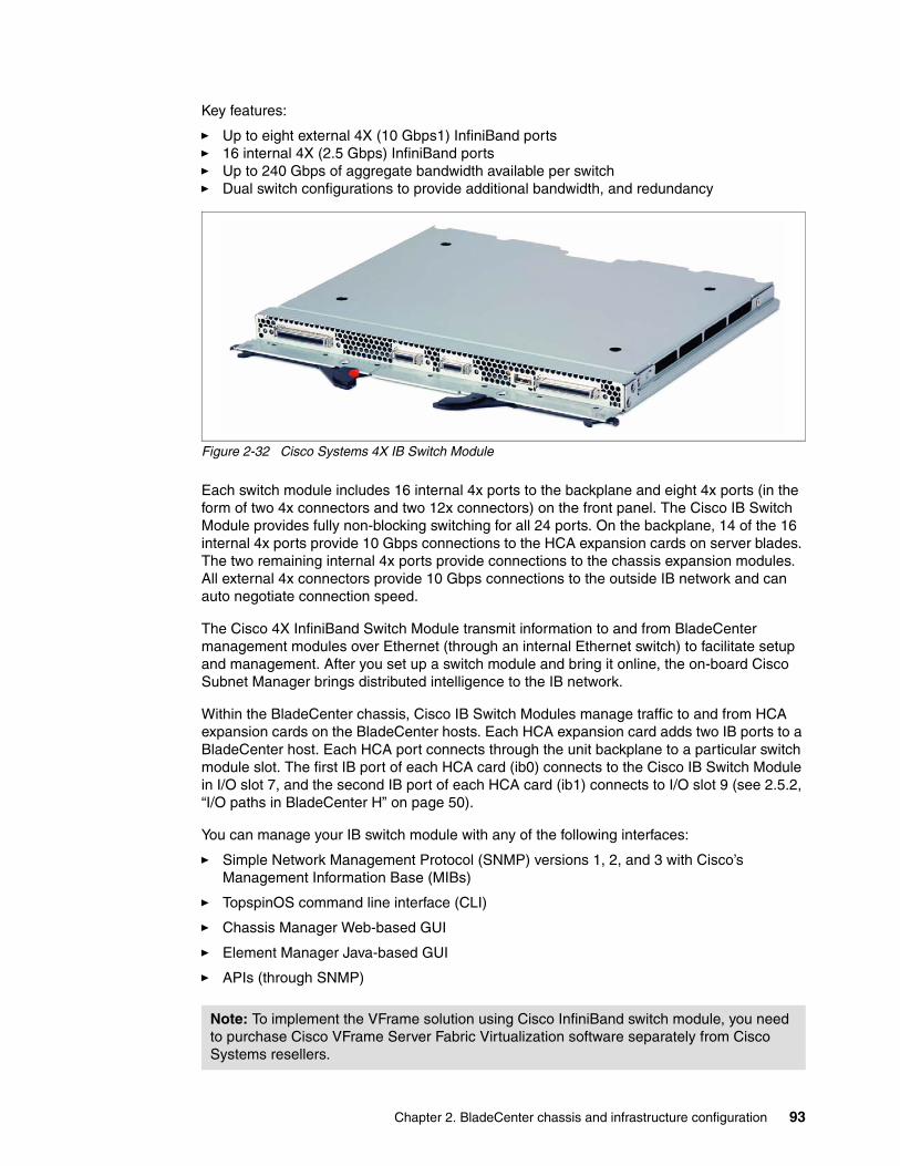
Chapter 2. BladeCenter chassis and infrastructure configuration 93
Key features:
� Up to eight external 4X (10 Gbps1) InfiniBand ports� 16 internal 4X (2.5 Gbps) InfiniBand ports� Up to 240 Gbps of aggregate bandwidth available per switch� Dual switch configurations to provide additional bandwidth, and redundancy
Figure 2-32 Cisco Systems 4X IB Switch Module
Each switch module includes 16 internal 4x ports to the backplane and eight 4x ports (in the form of two 4x connectors and two 12x connectors) on the front panel. The Cisco IB Switch Module provides fully non-blocking switching for all 24 ports. On the backplane, 14 of the 16 internal 4x ports provide 10 Gbps connections to the HCA expansion cards on server blades. The two remaining internal 4x ports provide connections to the chassis expansion modules. All external 4x connectors provide 10 Gbps connections to the outside IB network and can auto negotiate connection speed.
The Cisco 4X InfiniBand Switch Module transmit information to and from BladeCenter management modules over Ethernet (through an internal Ethernet switch) to facilitate setup and management. After you set up a switch module and bring it online, the on-board Cisco Subnet Manager brings distributed intelligence to the IB network.
Within the BladeCenter chassis, Cisco IB Switch Modules manage traffic to and from HCA expansion cards on the BladeCenter hosts. Each HCA expansion card adds two IB ports to a BladeCenter host. Each HCA port connects through the unit backplane to a particular switch module slot. The first IB port of each HCA card (ib0) connects to the Cisco IB Switch Module in I/O slot 7, and the second IB port of each HCA card (ib1) connects to I/O slot 9 (see 2.5.2, “I/O paths in BladeCenter H” on page 50).
You can manage your IB switch module with any of the following interfaces:
� Simple Network Management Protocol (SNMP) versions 1, 2, and 3 with Cisco’s Management Information Base (MIBs)
� TopspinOS command line interface (CLI)
� Chassis Manager Web-based GUI
� Element Manager Java-based GUI
� APIs (through SNMP)
Note: To implement the VFrame solution using Cisco InfiniBand switch module, you need to purchase Cisco VFrame Server Fabric Virtualization software separately from Cisco Systems resellers.
94 IBM BladeCenter Products and Technology
Table 2-32 shows Cisco 4X InfiniBand switch module-related options:
Table 2-32 Cisco 4X InfiniBand switch module options
Refer to the following for more information:
� Cisco 4X InfiniBand Switch Module for IBM BladeCenter User Guide
http://www.ibm.com/systems/support/supportsite.wss/docdisplay?brandind=5000020&lndocid=MIGR-65966
Part number Description
26R0816 InfiniBand 3 meter 12x to (3) 4x Cable for IBM BladeCenter
26R0849 InfiniBand 8 meter 12x to (3) 4x Cable for IBM BladeCenter
26R0813 InfiniBand 3 meter 4x Cable for IBM BladeCenter
26R0847 InfiniBand 8 meter 4x Cable for IBM BladeCenter
Chapter 7. SAPR Guide body 95
2.11 Installation and physical site plans
The IBM BladeCenter chassis, the BladeCenter T chassis, the BladeCenter H chassis, and all blade servers are designated as a customer setup. Customer setup instructions are shipped with the systems or can be downloaded from IBM Support Web site. Refer to product publications listed in “Related publications” on page 189 for installation instructions.
These product publications can be downloaded in PDF format from the BladeCenter Support site:
http://www-304.ibm.com/jct01004c/systems/support/supportsite.wss/brandmain?brandind=5000020
2.11.1 Physical planning
Here are the physical planning specifications and weight considerations.
Physical specificationsAn IBM BladeCenter type 8677 unit has the following specifications:
� Height: 304 mm (12 in. or 7 U)
� Depth: 711 mm (28 in.)
� Width: 444 mm (17.5 in.)
� Weight:
– Fully configured with modules and blades: Approximately 108.86 kg (240 lb.)– Fully configured without blades: Approximately 44.91 kg (99 lb.)
� A BladeCenter unit uses 7U of vertical rack space.
� Acoustical noise emissions:
– Without acoustics module option:• Sound power, idle: 7.4 bels maximum• Sound power, operating: 7.4 bels maximum
– With acoustics module option:• Sound power, idle: 6.9 bels maximum• Sound power, operating: 6.9 bels maximum
� Electrical input:
– Sine-wave input (50-60 Hz single-phase) required– Input voltage:
• Minimum: 200 V ac• Maximum: 240 V ac
An IBM BladeCenter T type 8720 unit has the following specifications:
� Height: 349 mm (13.75 in. or 8 U)
� Depth: 508 mm (20 in.) from front of chassis to rear I/O connector plane. Maximum depth: 600 mm (23.62 in.) including bezel, handles, and cable bend radius
� Width: 442 mm (17.4 in.)
� Weight:
– Fully configured with modules and blade servers: Approximately 86.64 kg (191 lb.)– Fully configured without blade servers: Approximately 44.45 kg (98 lb.)
� A BladeCenter T unit uses 8U of vertical rack space
96 IBM BladeCenter Products and Technology
� Declared acoustical noise emission levels for normal operations:
– Sound-power levels (upper-limit): 7.8 bels– Sound-pressure levels (average), for four one-meter bystander positions: 63 dBA
� Electrical input:
– dc power– Input voltage: -48 V dc (-40 V dc to -60 V dc)
An IBM BladeCenter T type 8730 unit has the following specifications:
� Height: 349 mm (13.75 in. or 8 U)
� Depth: 508 mm (20 in.) from front of chassis to rear I/O connector plane. Maximum depth: 600 mm (23.62 in.) including bezel, handles, and cable bend radius
� Width: 442 mm (17.4 in.)
� Weight:
– Fully configured with modules and blade servers: Approximately 86.64 kg (191 lb.)– Fully configured without blade servers: Approximately 44.45 kg (98 lb.)
� A BladeCenter T unit uses 8U of vertical rack space
� Declared acoustical noise emission levels for normal operations:
– Sound-power levels (upper-limit): 7.8 bels– Sound-pressure levels (average), for four one-meter bystander positions: 63 dBA
� Electrical input:
– Sine-wave input (50 or 60 Hz single-phase) required– Input voltage:
• Minimum: 200 V ac• Maximum: 240 V ac
An IBM BladeCenter H type 8852 unit has the following dimensions:
� Height: 400 mm (15.75 in. or 9 U)
� Depth: 711 mm (28 in.)
� Width: 482 mm (19 in.)
� Weight:
– Full configured weight with blade servers: Approximately 158.8 kg (350 lb.)– Empty chassis without modules or blade servers: Approximately 40.82 kg (90 lb.)
� Acoustics:
– Declared sound power level: 7.5 bels
� Electrical input:
– Sine-wave input (50-60 Hz single-phase) required– Input voltage:
• Minimum: 200 V ac• Maximum: 240 V ac
Weight considerationsThe following factors are important when planning for the physical installation of BladeCenter units:
� Racks have a maximum weight load limit.
� Floors, particularly raised floors have maximum weight limits.
Chapter 7. SAPR Guide body 97
Specific requirements are available in the following documentation:
� BladeCenter type 8677 - Planning and Installation Guide� BladeCenter T types 8720 and 8730 - Planning and Installation Guide� BladeCenter H type 8852 - Installation and User Guide
You can find this documentation under publications in the relevant product section in the BladeCenter Support site:
http://www-304.ibm.com/jct01004c/systems/support/supportsite.wss/brandmain?brandind=5000020
2.11.2 Rack installation
IBM intends for you to install and secure the BladeCenter, BladeCenter T, and BladeCenter H in a rack. You can download the IBM System x rack configurator from:
http://www.ibm.com/servers/eserver/xseries/library/configtools.html
When planning for racks, you must consider the following factors:
� Floor space that provides adequate access to the front and rear of the rack, and space on both sides of the rack or a row of racks for ventilation and walk through space.
� Rack weight load limits and floor weight load limits.
� Rack height – each BladeCenter unit requires 7U (BladeCenter T unit requires 8U; BladeCenter H unit requires 9U), also consider the space needed for other equipment that might be installed in the same rack with the BladeCenter units.
� The BladeCenter, BladeCenter T and BladeCenter H unit can only be installed horizontally.
� Three or more people are required to install the device in a rack cabinet, after all the blade servers are removed.
� Do not leave any unused U space within a rack cabinet open. Blank filler panels must be used to prevent recirculation of warm air.
� Install your BladeCenter unit only in a rack cabinet with perforated front and rear doors.
� Install your BladeCenter or BladeCenter H in a rack that meets the following requirements:
– Minimum depth of 70 mm (2.76 in.) between the front mounting flange and inside of the front door.
– Minimum depth of 157 mm (6.18 in.) between the rear mounting flange and inside of the rear door.
– Minimum depth of 559 mm (22 in.) and maximum depth of 762 mm (30 in.) between the front and rear mounting flanges.
� IBM BladeCenter T can be installed into standard rack, 2-post rack for Telco, 4-post rack for Telco, or UTF (Universal Telco Frame) rack
Specific requirements are available in the following documentation:
� BladeCenter type 8677 - Rack Installation Instructions� BladeCenter T types 8720 and 8730 - Rack Installation Instructions� BladeCenter H type 8852 - Rack Installation Instructions
You can find the documentation under publications in the relevant product section at:
http://www-304.ibm.com/jct01004c/systems/support/supportsite.wss/brandmain?brandind=5000020
98 IBM BladeCenter Products and Technology
The following are not included and must be supplied separately:
– Mouse– Keyboard– Display– Network cables
2.11.3 Power considerations
Different IBM BladeCenter chassis have a different power topologies inside as discussed in 2.3, “Power modules” on page 41. You will find additional information in this section.
Remember, that all three BladeCenter chassis have two power domains, and each BladeCenter chassis comes with two power supplies which provides power for power domain A. If you plan to install any devices in power domain B then you must use additional two power supplies for domain B. They are ordered as a single option containing two power supplies.
For a detailed discussion of power management in the IBM BladeCenter, refer to BladeCenter packaging, power, and cooling, in the IBM Journal of Research and Development, available from:
http://www.research.ibm.com/journal/rd49-6.html
IBM BladeCenter 8677 specific considerationsIBM BladeCenter 8677 chassis shipped earlier may have different types of power supplies: 1200W, 1400W, 1800W, or 2000W. Only 2000W power supplies are supported with blade servers shipping currently, so if you plan to install new blades into existing BladeCenter 8677 chassis you must plan to upgrade you power supplies to 2000W in power domains, where you plan to install these new blades. You must install the power modules in pairs in a domain, and they must match each other in capacity (wattage, amperage, and so on).
Only 2000W power supplies are available now. All others were withdrawn from market. See 2.3.1, “Power modules for IBM BladeCenter” on page 42.
To provide true redundant power, BladeCenter 8677 power modules 1 and 3 must be connected to a different 200-240 Volt ac power source than power modules 2 and 4. An installed power module must be connected to an ac power source and must not be used as a filler.
Under some conditions blades in a fully populated chassis may consume more power than a single power supply in a domain can deliver. In case of power supply failure in a domain some blades may be throttled to accommodate the capacity of remaining power supply. Throttling
Note: IBM has tested and offers rack kits for NEBS and ETSI Seismic racks. Do not place racks directly against a wall because, if service is needed, the service representative will need access to the back of the BladeCenter T unit.
Note: The BladeCenter chassis type 8677, BladeCenter T chassis type 8730 (AC), and BladeCenter H chassis can only be powered with 220V world-wide! Your data center must be able to supply this voltage.
Note: The BladeCenter T chassis type 8720 must be installed by personnel trained in DC wiring installations. Setup instructions are shipped with the systems.
Chapter 7. SAPR Guide body 99
means that blades reduce their power consumption by decreasing the processor frequency, and as soon as power will be restored the blades are returned to their full frequency operations. This process is controlled by management module, and this technique is a part of IBM PowerExecutive initiative.
IBM PowerExecutive monitors actual power draw of blade servers (if supported by blade) and in rare case of power supply failure it throttles some blades to stay within remaining power. It is done on a hardware level independently of the operating system.
If throttling is absolutely unacceptable to the client then you have to limit the number of blades installed into the chassis.
IBM BladeCenter Power Calculator tool should be used for estimation of power consumption for the specific configuration. It shows power consumption for each power domain and overall power consumption as well as other characteristics. This tool can be downloaded from:
http://www.ibm.com/systems/bladecenter/powerconfig/
In any configuration the total power consumption for the single IBM BladeCenter chassis must not exceed 5400W.
IBM BladeCenter should be attached to high-voltage PDUs as described in 2.11.5, “Cabling considerations” on page 104.
Refer to 2.3.1, “Power modules for IBM BladeCenter” on page 42 for additional information.
IBM BladeCenter H specific considerationsBladeCenter H chassis comes with two 2900W power supplies. Additional 2900W power supplies for power domain B is available as an option as described in 2.3.2, “Power modules for IBM BladeCenter H” on page 43.
Remember that power cables for BladeCenter H are not shipped either with chassis nor with optional power supplies, and must be purchased separately. IBM BladeCenter H has only two specific power connectors, they must be connected to a different 200-240 Volt ac power sources to provide true redundancy.
IBM BladeCenter H provides PowerExecutive capabilities to monitor actual power draw if supported by blades. However, it is not necessary to do throttling now, because each power supply is capable to supplying enough power to the blades in each power domain in any configuration.
BM BladeCenter Power Calculator tool should be used for estimation of power consumption for the specific configuration. It shows power consumption for each power domain and overall power consumption as well as other characteristics. This tool can be downloaded from:
http://www.ibm.com/systems/bladecenter/powerconfig/
In any configuration the total power consumption for the single IBM BladeCenter H chassis must not exceed 8000W.
IBM BladeCenter H should be attached to high-voltage PDUs as described in 2.11.5, “Cabling considerations” on page 104.
See 2.3.2, “Power modules for IBM BladeCenter H” on page 43 for additional information.
100 IBM BladeCenter Products and Technology
IBM BladeCenter T specific considerationsIBM BladeCenter T ships with two 1300W AC (8730) or DC (8720) power supplies. Additional 1300W power supplies for power domain B is available as an option as described in 2.3.3, “Power modules for IBM BladeCenter T” on page 45.
To provide true redundant power, BladeCenter T power modules 1 and 3 must be connected to a different power source than power modules 2 and 4.
Under some conditions blades in a fully populated chassis may consume more power than a single power supply in a domain can deliver. In case of power supply failure in a domain some blades may be throttled to accommodate the capacity of remaining power supply. Throttling means that blades reduce their power consumption by decreasing the processor frequency, and as soon as power will be restored the blades are returned to their full frequency operations. This process is controlled by management module, and this technique is a part of IBM PowerExecutive initiative.
IBM PowerExecutive monitors actual power draw of blade servers (if supported by blade) and in rare case of power supply failure it throttles some blades to stay within remaining power. It is done on a hardware level independently of the operating system.
If throttling is absolutely unacceptable to the client then you have to limit the number of blades installed into the chassis.
IBM BladeCenter Power Calculator tool should be used for estimation of power consumption for the specific configuration. It shows power consumption for each power domain and overall power consumption as well as other characteristics. This tool can be downloaded from:
http://www.ibm.com/systems/bladecenter/powerconfig/
In any configuration the total power consumption for the single IBM BladeCenter T chassis must not exceed 3000W.
IBM BladeCenter T 8730 should be attached to high-voltage PDUs as described in 2.11.5, “Cabling considerations” on page 104.
IBM BladeCenter T 8720 should be attached to the appropriate DC wiring as described in 2.11.5, “Cabling considerations” on page 104.
See 2.3.3, “Power modules for IBM BladeCenter T” on page 45 for additional information.
2.11.4 Cooling considerations
When planning a data center, take the following points into consideration regarding cooling.
Air temperatureThe permissible temperatures and humidity limits for different BladeCenter chassis are:
� IBM BladeCenter
– On: 10.0 to 35.0 degrees C (50 to 95 degrees F) at 0 to 914 m (0 to 3,000 ft)
– On: 10.0 to 32.0 degrees C (50 to 90 degrees F) at 914 to 2,133 m (3,000 to 7,000 ft)
– Off: -40 to 60 degrees C (-40 to 140 degrees F)
– Relative humidity:
• On: 8% to 80%• Off: 8% to 80%
– Maximum altitude: 2,133 m (7,000 ft)
Chapter 7. SAPR Guide body 101
� IBM BladeCenter H
– On: 10.0 to 35.0 degrees C (50 to 95 degrees F) at 0 to 914 m (0 to 3,000 ft)
– On: 10.0 to 32.0 degrees C (50 to 90 degrees F) at 914 to 2,133 m (3,000 to 7,000 ft)
– Off: -40 to 60 degrees C (-40 to 140 degrees F)
– Relative humidity:
• On: 8% to 80%• Off: 8% to 80%
– Maximum altitude: 2,133 m (7,000 ft)
� IBM BladeCenter T 8720 (NEBS/Telecom)
– On: 5 to 40 degrees C (41 to 104 degrees F) Altitude: -60 m (-197 ft) to 1800 m (6000 ft)
– On (short term): -5 to 55 degrees C (23 to 131 degrees F) Altitude: -60 m (-197 ft) to 1800 m (6000 ft)
– On: 5 to 30 degrees C (41 to 86 degrees F) Altitude: 1800 m (600 ft) to 4000 m (13,000 ft)
– On (short term): -5 to 45 degrees C (23 to 113 degrees F) Altitude: 1800 m (6000 ft) to 4000 m (13,000 ft)
– Off: -40 to 70 degrees C (-40 to 158 degrees F)
– Rate of temperature change 30 degrees C/hr (54 degrees F/hr)
– Humidity:
• On: 5% to 85%• On (short term): 5% to 90% but not to exceed 0.024 kg water/kg of dry air• Off: uncontrolled
Short term is a period of not more than 96 consecutive hours and a total of not more than 15 days in one year. (This refers to a total of 360 hours in any given year, but, no more than 15 occurrences during that one-year period.)
– Maximum altitude: 4,000 m (13,000 ft)
� IBM BladeCenter T 8730 (non-NEBS)
– On: 5.0 to 35.0 degrees C (41 to 95 degrees F) at -60 to 1800 m (-197 to 6,000 ft)– On: 5.0 to 32.0 degrees C (41 to 90 degrees F) at 1800 to 4000 m (6,000 to 13,000 ft)– Off: uncontrolled– Relative humidity:
• On: 5% to 85%• Off: uncontrolled
– Maximum altitude: 4,000 m (13,000 ft)
Air flowAir flow is critical for ensuring the operating air temperature stays within permissible limits. The blowers used in each chassis type are described in 2.2, “Blower modules” on page 38.
� Air flow direction is from front to back.
� All BladeCenter chassis bays must be populated, either with a module, a blade server, or a filler in place of the component. If a location is left empty for more than one minute while the BladeCenter unit is operating, performance degradation or thermal failures may occur.
� All equipment installed in a rack with a BladeCenter unit must use front to back air flow to prevent warm air recirculation problems. Devices that use back to front air flow causes
102 IBM BladeCenter Products and Technology
warm air to enter the front of the BladeCenter unit. This can cause reduced reliability, component failure, data loss, or server shutdown.
� In racks with multiple BladeCenter units, populate the BladeCenter chassis starting with the bottom chassis in the rack and working up towards the top of the rack.
� Any unused rack space must be covered with a blank rack filler panel to ensure proper air circulation.
� The BladeCenter T unit comes with a bezel assembly containing a removable and replaceable air filter. There are software features in the management-module that detect a clogged filter and generate system alerts based on the severity of the airflow reduction. The typical service interval for the filter is approximately three to six months depending on your environment.
Heat outputThe amount of heat output of BladeCenter chassis in BTU per hour is as follows:
� IBM BladeCenter
– Maximum configuration: 18425 BTU/hour (5400W)
� IBM BladeCenter H
– Maximum configuration: 27280 BTU/hour (8000W)
� IBM BladeCenter T 8720
– Maximum configuration: 11229 BTU/hour (3291W)
� IBM BladeCenter T 8730
– Maximum configuration: 10440 BTU/hour (3060W)
Prevention of air recirculationConsider these factors when planning for single or multiple rack installations:
� When racks are positioned adjacent to each other, ensure the racks fit tightly together from side to side to prevent inter-rack air recirculation from the back to the front.
� Air recirculation occurs over the top or around the side of a rack in a room that does not have a cooling system with sufficient airflow volume capacity. Ensure that the cooling system has adequate capacity for the room cooling load.
Room coolingTo prevent possible BladeCenter thermal failures proper room cooling is vital:
� Ensure that the site cooling system has adequate capacity for the room cooling load.
� Ensure that cool air is provided to the front of the BladeCenter unit and rack.
� Ensure that the room cooling system is positioned so warm exhaust air is directed away from all BladeCenter units towards the room cooling system without passing in front of a BladeCenter unit.
� A significant air temperature gradient can occur from the bottom to the top of a rack in a room which has a cooling system that does not have sufficient airflow volume and cooling capacity. This may cause equipment at the top of the rack to run hot resulting in reduced reliability, component failure, data loss, or server shut down.
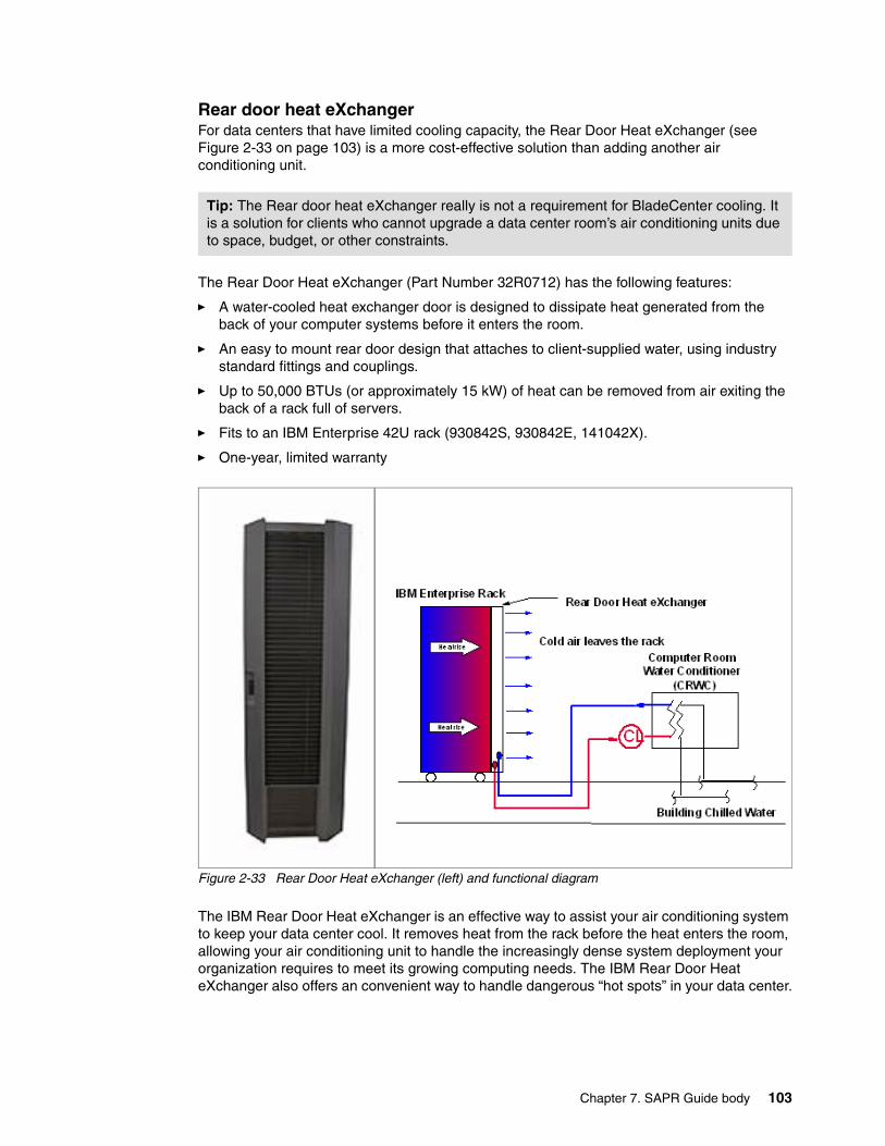
Chapter 7. SAPR Guide body 103
Rear door heat eXchangerFor data centers that have limited cooling capacity, the Rear Door Heat eXchanger (see Figure 2-33 on page 103) is a more cost-effective solution than adding another air conditioning unit.
The Rear Door Heat eXchanger (Part Number 32R0712) has the following features:
� A water-cooled heat exchanger door is designed to dissipate heat generated from the back of your computer systems before it enters the room.
� An easy to mount rear door design that attaches to client-supplied water, using industry standard fittings and couplings.
� Up to 50,000 BTUs (or approximately 15 kW) of heat can be removed from air exiting the back of a rack full of servers.
� Fits to an IBM Enterprise 42U rack (930842S, 930842E, 141042X).
� One-year, limited warranty
Figure 2-33 Rear Door Heat eXchanger (left) and functional diagram
The IBM Rear Door Heat eXchanger is an effective way to assist your air conditioning system to keep your data center cool. It removes heat from the rack before the heat enters the room, allowing your air conditioning unit to handle the increasingly dense system deployment your organization requires to meet its growing computing needs. The IBM Rear Door Heat eXchanger also offers an convenient way to handle dangerous “hot spots” in your data center.
Tip: The Rear door heat eXchanger really is not a requirement for BladeCenter cooling. It is a solution for clients who cannot upgrade a data center room’s air conditioning units due to space, budget, or other constraints.
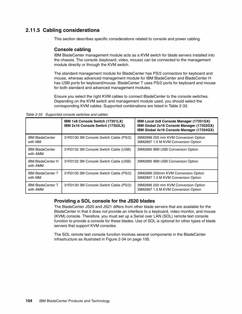
104 IBM BladeCenter Products and Technology
2.11.5 Cabling considerations
This section describes specific considerations related to console and power cabling.
Console cablingIBM BladeCenter management module acts as a KVM switch for blade servers installed into the chassis. The console (keyboard, video, mouse) can be connected to the management module directly or through the KVM switch.
The standard management module for BladeCenter has PS/2 connectors for keyboard and mouse, whereas advanced management module for IBM BladeCenter and BladeCenter H has USB ports for keyboard/mouse. BladeCenter T uses PS/2 ports for keyboard and mouse for both standard and advanced management modules.
Ensure you select the right KVM cables to connect BladeCenter to the console switches. Depending on the KVM switch and management module used, you should select the corresponding KVM cables. Supported combinations are listed in Table 2-33.
Table 2-33 Supported console switches and cables
Providing a SOL console for the JS20 bladesThe BladeCenter JS20 and JS21 differs from other blade servers that are available for the BladeCenter in that it does not provide an interface to a keyboard, video monitor, and mouse (KVM) console. Therefore, you must set up a Serial over LAN (SOL) remote text console function to provide a console for these blades. Use of SOL is optional for other types of blade servers that support KVM consoles.
The SOL remote text console function involves several components in the BladeCenter infrastructure as illustrated in Figure 2-34 on page 105.
IBM 1x8 Console Switch (17351LX)IBM 2x16 Console Switch (17352LX)
IBM Local 2x8 Console Manager (17351GX)IBM Global 2x16 Console Manager (17352GX)IBM Global 4x16 Console Manager (17354GX)
IBM BladeCenter with MM
31R3130 3M Console Switch Cable (PS/2) 39M2896 250 mm KVM Conversion Option39M2897 1.5 M KVM Conversion Option
IBM BladeCenter with AMM
31R3132 3M Console Switch Cable (USB) 39M2895 IBM USB Conversion Option
IBM BladeCenter H with AMM
31R3132 3M Console Switch Cable (USB) 39M2895 IBM USB Conversion Option
IBM BladeCenter T with MM
31R3130 3M Console Switch Cable (PS/2) 39M2896 250mm KVM Conversion Option39M2897 1.5 M KVM Conversion Option
IBM BladeCenter T with AMM
31R3130 3M Console Switch Cable (PS/2) 39M2896 250 mm KVM Conversion Option39M2897 1.5 M KVM Conversion Option
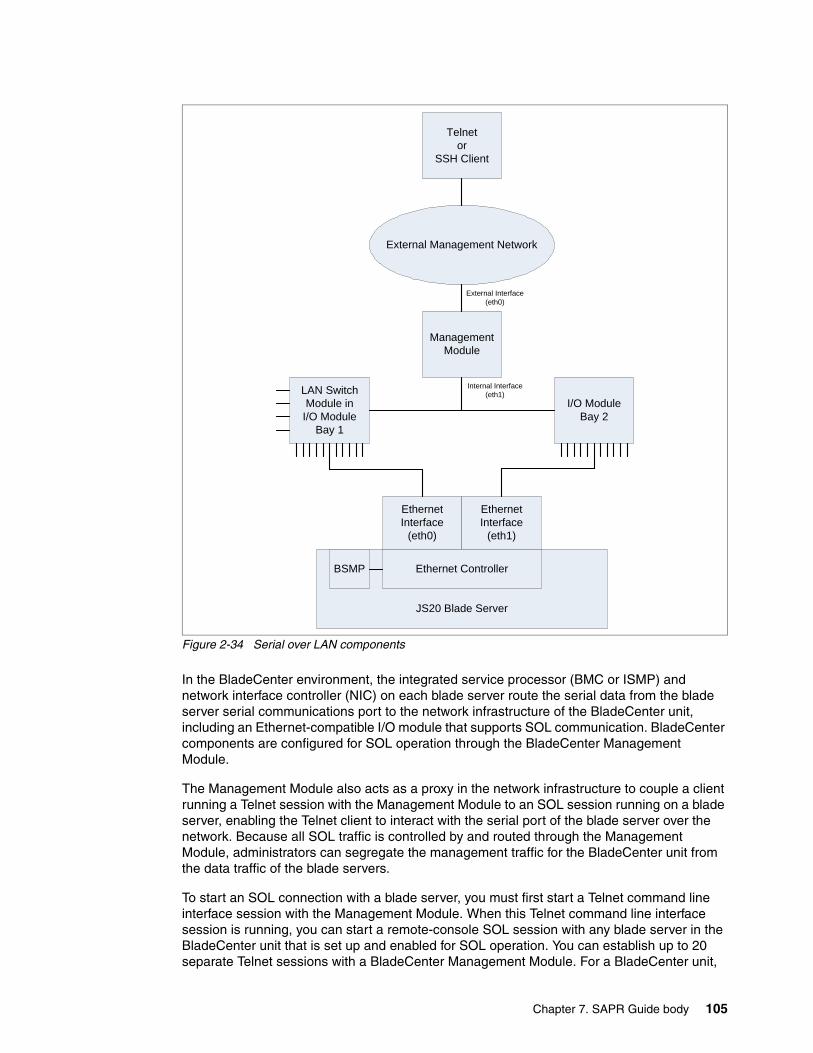
Chapter 7. SAPR Guide body 105
Figure 2-34 Serial over LAN components
In the BladeCenter environment, the integrated service processor (BMC or ISMP) and network interface controller (NIC) on each blade server route the serial data from the blade server serial communications port to the network infrastructure of the BladeCenter unit, including an Ethernet-compatible I/O module that supports SOL communication. BladeCenter components are configured for SOL operation through the BladeCenter Management Module.
The Management Module also acts as a proxy in the network infrastructure to couple a client running a Telnet session with the Management Module to an SOL session running on a blade server, enabling the Telnet client to interact with the serial port of the blade server over the network. Because all SOL traffic is controlled by and routed through the Management Module, administrators can segregate the management traffic for the BladeCenter unit from the data traffic of the blade servers.
To start an SOL connection with a blade server, you must first start a Telnet command line interface session with the Management Module. When this Telnet command line interface session is running, you can start a remote-console SOL session with any blade server in the BladeCenter unit that is set up and enabled for SOL operation. You can establish up to 20 separate Telnet sessions with a BladeCenter Management Module. For a BladeCenter unit,
Telnetor
SSH Client
ManagementModule
LAN Switch Module inI/O Module
Bay 1
I/O ModuleBay 2
EthernetInterface
(eth0)
EthernetInterface
(eth1)
Ethernet ControllerBSMP
JS20 Blade Server
External Management Network
External Interface (eth0)
Internal Interface (eth1)
106 IBM BladeCenter Products and Technology
this enables you to have 14 simultaneous SOL sessions active (one for each of up to 14 blade servers) with six additional command line interface sessions available for BladeCenter unit management. For a BladeCenter T unit, this enables you to have eight simultaneous SOL sessions active (one for each of up to eight blade servers) with 12 additional command line interface sessions available for BladeCenter unit management. If security is a concern, you can use Secure Shell (SSH) sessions to establish secure Telnet command line interface sessions with the BladeCenter Management Module before starting an SOL console redirect session with a blade server.
We summarize the steps involved:
1. Using a Telnet or SSH client, connect to the BladeCenter Management Module CLI. This is usually via an external management network that is connected to the Management Module’s 10/100BaseT Ethernet interface.
2. From the Management Module’s CLI, initiate an SOL remote console session to the desired blade server.
3. The Management Module uses a private VLAN provided by the LAN switch module in I/O module bay 1, to transport the SOL data stream to the Ethernet interface of the target blade server.
4. The Ethernet controller of the target blade server passes the SOL data stream received from the private VLAN to the blade system management processor (BSMP), which manages the text console for the blade server.
Take the following points into consideration when using Serial over LAN (SOL):
� A SOL-capable Ethernet network switch must be present in module bay 1 of the BladeCenter chassis
� You cannot use the OPM (Optical Pass-thru Module) or the CPM (Copper Pass-thru Module) for an SOL connection.
� SOL uses the first network interface, Ethernet 1 (eth1 or Planar Ethernet 1), of the blade server to communicate. When this network interface attempts to boot through PXE or DHCP, the network interface is reset, causing the current SOL session to be dropped and have a new status of Not Ready. If you require booting through PXE or DHCP, use the second network interface, Ethernet 2 (eth2 or Planar Ethernet 2), of the blade server and install an SOL-capable Ethernet I/O module in I/O-module bay 1.
� Access to the SOL remote text console function is via the Management Module CLI (command line interface). The CLI is documented in the IBM BladeCenter Management Module Command Line Interface Reference Guide.
� The Management Module can support up to 20 concurrent CLI connections. This is sufficient to support the concurrent use of a SOL remote text console to each blade server in a full BladeCenter chassis. At the same time, the Management Module supports six additional CLI connections for other administrative activities.
For detailed documentation about how to set up and manage SOL connections for your specific environment, refer to:
� Serial over LAN (SOL) Setup Guide - IBM BladeCenter T, available from:
http://www.ibm.com/systems/support/supportsite.wss/docdisplay?brandind=5000020&lndocid=MIGR-54666
Restriction: You can only have one active SOL remote text console connection to each blade server.
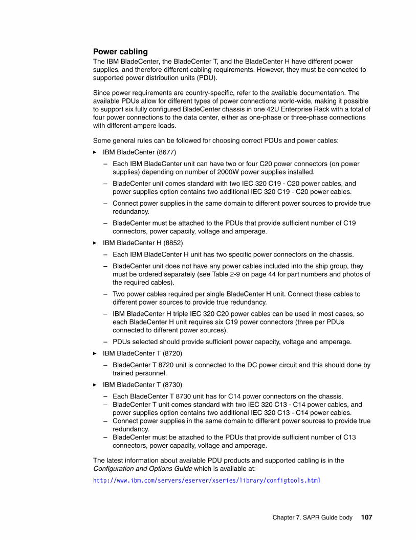
Chapter 7. SAPR Guide body 107
Power cablingThe IBM BladeCenter, the BladeCenter T, and the BladeCenter H have different power supplies, and therefore different cabling requirements. However, they must be connected to supported power distribution units (PDU).
Since power requirements are country-specific, refer to the available documentation. The available PDUs allow for different types of power connections world-wide, making it possible to support six fully configured BladeCenter chassis in one 42U Enterprise Rack with a total of four power connections to the data center, either as one-phase or three-phase connections with different ampere loads.
Some general rules can be followed for choosing correct PDUs and power cables:
� IBM BladeCenter (8677)
– Each IBM BladeCenter unit can have two or four C20 power connectors (on power supplies) depending on number of 2000W power supplies installed.
– BladeCenter unit comes standard with two IEC 320 C19 - C20 power cables, and power supplies option contains two additional IEC 320 C19 - C20 power cables.
– Connect power supplies in the same domain to different power sources to provide true redundancy.
– BladeCenter must be attached to the PDUs that provide sufficient number of C19 connectors, power capacity, voltage and amperage.
� IBM BladeCenter H (8852)
– Each IBM BladeCenter H unit has two specific power connectors on the chassis.
– BladeCenter unit does not have any power cables included into the ship group, they must be ordered separately (see Table 2-9 on page 44 for part numbers and photos of the required cables).
– Two power cables required per single BladeCenter H unit. Connect these cables to different power sources to provide true redundancy.
– IBM BladeCenter H triple IEC 320 C20 power cables can be used in most cases, so each BladeCenter H unit requires six C19 power connectors (three per PDUs connected to different power sources).
– PDUs selected should provide sufficient power capacity, voltage and amperage.
� IBM BladeCenter T (8720)
– BladeCenter T 8720 unit is connected to the DC power circuit and this should done by trained personnel.
� IBM BladeCenter T (8730)
– Each BladeCenter T 8730 unit has for C14 power connectors on the chassis.– BladeCenter T unit comes standard with two IEC 320 C13 - C14 power cables, and
power supplies option contains two additional IEC 320 C13 - C14 power cables.– Connect power supplies in the same domain to different power sources to provide true
redundancy.– BladeCenter must be attached to the PDUs that provide sufficient number of C13
connectors, power capacity, voltage and amperage.
The latest information about available PDU products and supported cabling is in the Configuration and Options Guide which is available at:
http://www.ibm.com/servers/eserver/xseries/library/configtools.html

108 IBM BladeCenter Products and Technology
We also strongly recommend that you read information available in:
� BladeCenter type 8677 - Planning and Installation Guide� BladeCenter T types 8720 and 8730 - Planning and Installation Guide� BladeCenter H type 8852 - Installation and User Guide
These documents cover the following details:
� Physical planning� Rack consideration� Power consideration� Cooling consideration� Power connections (PDUs and cables)� Physical installation time
You can find this documentation under publications in the relevant product section, for example, BladeCenter 8677 or BladeCenter T 8720 or 8730, or BladeCenter H 8852 at:
http://www-304.ibm.com/jct01004c/systems/support/supportsite.wss/brandmain?brandind=5000020
Refer to 2.3, “Power modules” on page 41 for additional information.
© Copyright IBM Corp. 2007. All rights reserved. 109
Chapter 3. Blade server hardware configuration
This chapter describes, in detail, the hardware configuration of different blade servers and expansion options.
� 3.1, “HS21 type 8853” on page 110� 3.2, “HS20 type 8843” on page 117� 3.3, “HS20 type 7981” on page 124� 3.4, “LS20 type 8850” on page 129� 3.5, “LS21 type 7971” on page 133� 3.6, “LS41 type 7972” on page 140� 3.7, “JS20 type 8842” on page 148� 3.8, “JS21 type 8844” on page 151� 3.9, “BladeCenter Memory and I/O Expansion Unit” on page 155� 3.10, “BladeCenter Storage and I/O Expansion Unit” on page 156� 3.11, “BladeCenter PCI I/O Expansion Unit 2” on page 159� 3.12, “BladeCenter Expansion Cards” on page 160
These tables in Chapter 1 provide compatibility information:
� Table 1-1 on page 2 lists the blade servers that are supported in each chassis.
� Table 1-3 on page 3 lists the blade servers that support each of the expansion cards.
3
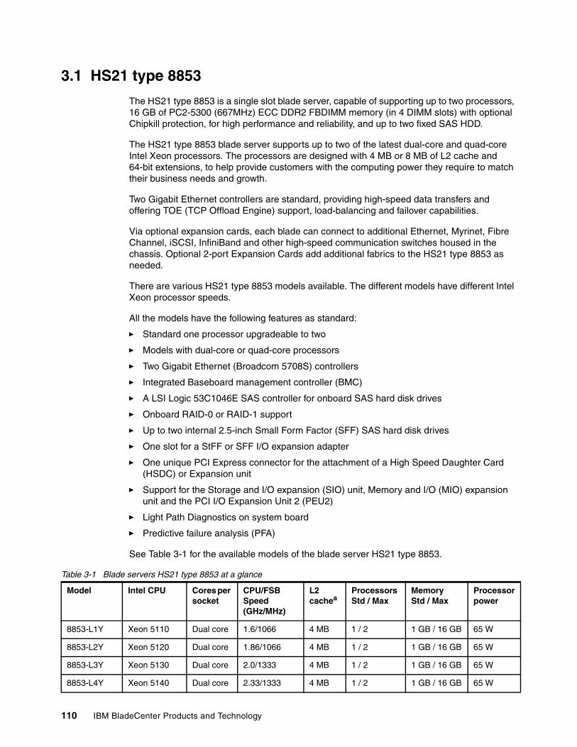
110 IBM BladeCenter Products and Technology
3.1 HS21 type 8853
The HS21 type 8853 is a single slot blade server, capable of supporting up to two processors, 16 GB of PC2-5300 (667MHz) ECC DDR2 FBDIMM memory (in 4 DIMM slots) with optional Chipkill protection, for high performance and reliability, and up to two fixed SAS HDD.
The HS21 type 8853 blade server supports up to two of the latest dual-core and quad-core Intel Xeon processors. The processors are designed with 4 MB or 8 MB of L2 cache and 64-bit extensions, to help provide customers with the computing power they require to match their business needs and growth.
Two Gigabit Ethernet controllers are standard, providing high-speed data transfers and offering TOE (TCP Offload Engine) support, load-balancing and failover capabilities.
Via optional expansion cards, each blade can connect to additional Ethernet, Myrinet, Fibre Channel, iSCSI, InfiniBand and other high-speed communication switches housed in the chassis. Optional 2-port Expansion Cards add additional fabrics to the HS21 type 8853 as needed.
There are various HS21 type 8853 models available. The different models have different Intel Xeon processor speeds.
All the models have the following features as standard:
� Standard one processor upgradeable to two
� Models with dual-core or quad-core processors
� Two Gigabit Ethernet (Broadcom 5708S) controllers
� Integrated Baseboard management controller (BMC)
� A LSI Logic 53C1046E SAS controller for onboard SAS hard disk drives
� Onboard RAID-0 or RAID-1 support
� Up to two internal 2.5-inch Small Form Factor (SFF) SAS hard disk drives
� One slot for a StFF or SFF I/O expansion adapter
� One unique PCI Express connector for the attachment of a High Speed Daughter Card (HSDC) or Expansion unit
� Support for the Storage and I/O expansion (SIO) unit, Memory and I/O (MIO) expansion unit and the PCI I/O Expansion Unit 2 (PEU2)
� Light Path Diagnostics on system board
� Predictive failure analysis (PFA)
See Table 3-1 for the available models of the blade server HS21 type 8853.
Table 3-1 Blade servers HS21 type 8853 at a glance
Model Intel CPU Cores per socket
CPU/FSB Speed (GHz/MHz)
L2 cachea
Processors Std / Max
Memory Std / Max
Processor power
8853-L1Y Xeon 5110 Dual core 1.6/1066 4 MB 1 / 2 1 GB / 16 GB 65 W
8853-L2Y Xeon 5120 Dual core 1.86/1066 4 MB 1 / 2 1 GB / 16 GB 65 W
8853-L3Y Xeon 5130 Dual core 2.0/1333 4 MB 1 / 2 1 GB / 16 GB 65 W
8853-L4Y Xeon 5140 Dual core 2.33/1333 4 MB 1 / 2 1 GB / 16 GB 65 W
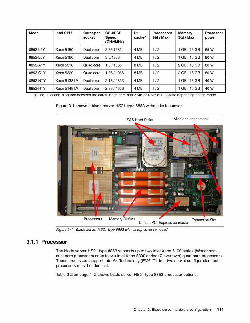
Chapter 3. Blade server hardware configuration 111
Figure 3-1 shows a blade server HS21 type 8853 without its top cover.
Figure 3-1 Blade server HS21 type 8853 with its top cover removed
3.1.1 Processor
The blade server HS21 type 8853 supports up to two Intel Xeon 5100 series (Woodcrest) dual-core processors or up to two Intel Xeon 5300 series (Clovertown) quad-core processors. These processors support Intel 64 Technology (EM64T). In a two socket configuration, both processors must be identical.
Table 3-2 on page 112 shows blade server HS21 type 8853 processor options.
8853-L5Y Xeon 5150 Dual core 2.66/1333 4 MB 1 / 2 1 GB / 16 GB 65 W
8853-L6Y Xeon 5160 Dual core 3.0/1333 4 MB 1 / 2 1 GB / 16 GB 80 W
8853-A1Y Xeon 5310 Quad core 1.6 / 1066 8 MB 1 / 2 2 GB / 16 GB 80 W
8853-C1Y Xeon 5320 Quad core 1.86 / 1066 8 MB 1 / 2 2 GB / 16 GB 80 W
8853-NTY Xeon 5138 LV Dual core 2.13 / 1333 4 MB 1 / 2 1 GB / 16 GB 40 W
8853-H1Y Xeon 5148 LV Dual core 2.33 / 1333 4 MB 1 / 2 1 GB / 16 GB 40 W
a. The L2 cache is shared between the cores. Each core has 2 MB or 4 MB of L2 cache depending on the model.
Model Intel CPU Cores per socket
CPU/FSB Speed (GHz/MHz)
L2 cachea
Processors Std / Max
Memory Std / Max
Processor power
Processors Memory DIMMs Expansion Slot
SAS Hard Disks Midplane connectors
Unique PCI Express connector
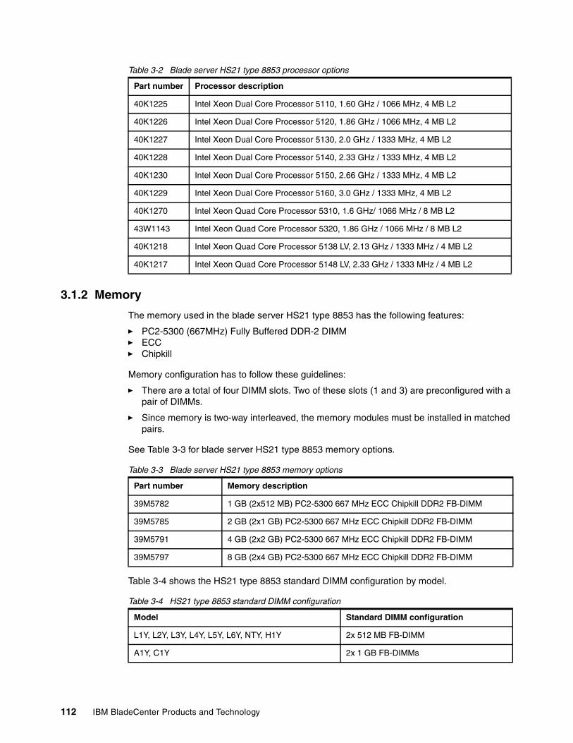
112 IBM BladeCenter Products and Technology
Table 3-2 Blade server HS21 type 8853 processor options
3.1.2 Memory
The memory used in the blade server HS21 type 8853 has the following features:
� PC2-5300 (667MHz) Fully Buffered DDR-2 DIMM� ECC� Chipkill
Memory configuration has to follow these guidelines:
� There are a total of four DIMM slots. Two of these slots (1 and 3) are preconfigured with a pair of DIMMs.
� Since memory is two-way interleaved, the memory modules must be installed in matched pairs.
See Table 3-3 for blade server HS21 type 8853 memory options.
Table 3-3 Blade server HS21 type 8853 memory options
Table 3-4 shows the HS21 type 8853 standard DIMM configuration by model.
Table 3-4 HS21 type 8853 standard DIMM configuration
Part number Processor description
40K1225 Intel Xeon Dual Core Processor 5110, 1.60 GHz / 1066 MHz, 4 MB L2
40K1226 Intel Xeon Dual Core Processor 5120, 1.86 GHz / 1066 MHz, 4 MB L2
40K1227 Intel Xeon Dual Core Processor 5130, 2.0 GHz / 1333 MHz, 4 MB L2
40K1228 Intel Xeon Dual Core Processor 5140, 2.33 GHz / 1333 MHz, 4 MB L2
40K1230 Intel Xeon Dual Core Processor 5150, 2.66 GHz / 1333 MHz, 4 MB L2
40K1229 Intel Xeon Dual Core Processor 5160, 3.0 GHz / 1333 MHz, 4 MB L2
40K1270 Intel Xeon Quad Core Processor 5310, 1.6 GHz/ 1066 MHz / 8 MB L2
43W1143 Intel Xeon Quad Core Processor 5320, 1.86 GHz / 1066 MHz / 8 MB L2
40K1218 Intel Xeon Quad Core Processor 5138 LV, 2.13 GHz / 1333 MHz / 4 MB L2
40K1217 Intel Xeon Quad Core Processor 5148 LV, 2.33 GHz / 1333 MHz / 4 MB L2
Part number Memory description
39M5782 1 GB (2x512 MB) PC2-5300 667 MHz ECC Chipkill DDR2 FB-DIMM
39M5785 2 GB (2x1 GB) PC2-5300 667 MHz ECC Chipkill DDR2 FB-DIMM
39M5791 4 GB (2x2 GB) PC2-5300 667 MHz ECC Chipkill DDR2 FB-DIMM
39M5797 8 GB (2x4 GB) PC2-5300 667 MHz ECC Chipkill DDR2 FB-DIMM
Model Standard DIMM configuration
L1Y, L2Y, L3Y, L4Y, L5Y, L6Y, NTY, H1Y 2x 512 MB FB-DIMM
A1Y, C1Y 2x 1 GB FB-DIMMs
Chapter 3. Blade server hardware configuration 113
BladeCenter Memory and I/O (MIO) expansion unitThe HS21 type 8853 also supports the attachment of one BladeCenter Memory and I/O (MIO) expansion unit. For more information about the MIO, see 3.9, “BladeCenter Memory and I/O Expansion Unit” on page 155.
3.1.3 Onboard network adapters
The HS21 type 8853 blade server includes two integrated Broadcom BCM5708S Gigabit Ethernet controllers. These two Ethernet interfaces are routed through to the redundant midplane providing a foundation for fault-tolerant network setups.
The following features are supported by the Broadcom (BCM5708S) onboard controllers:
� TOE (TCP Offload Engine)� iSCSI initiator� PXE 2.0 boot support� Wake on LAN® � Load-balancing� VLAN tagging support� Jumbo frame support (9KB)
The Broadcom Advanced Server Program (BASP) is management software provided by Broadcom for managing your network cards. This includes a command line interface for scripting purposes.
3.1.4 Integrated systems management processor
The blade server HS21 type 8853 has an integrated baseboard management controller (BMC) that provides:
� IPMI compliance (Intelligent Platform Management Interface)
� Serial over LAN (SOL)
� Wake on LAN (WOL)
� Power management functions
� KVM and media tray ownership
� Light path diagnostics support
� Automatic BIOS recovery (ABR)
� Automatic server restart (ASR)
� Predictive failure analysis (PFA) on system components (processor, memory, and hard disk drives)
� Inventory
� Error logging
� Environmental monitoring (voltages and temperature on the system board of the blade server)
Note: Ethernet Port 1 on the blade server is routed to the switch in module bay 1 and port 2 is routed to the switch in module bay 2. There is no way to connect both Ethernet ports to the same internal switch. To connect both ports to the same switch, would require an external gigabit Ethernet switch and either an OPM or CPM in module bays 1 and 2 in the BladeCenter chassis.
114 IBM BladeCenter Products and Technology
Note that you cannot access this onboard BMC externally through a dedicated port or daisy-chain it to other servers or blades. The BMC is forwarding information to the Management Module within the BladeCenter chassis. The management module is a single point of control for hardware management of all server and switch components contained within the chassis.
3.1.5 Local storage options
The HS21 type 8853 blade server features an onboard LSI Logic 53C1046E SAS controller with two SAS connectors for up to two optional 2.5-inch Small Form Factor (SFF) SAS hard disk drives. The LSI Logic 53C1046E SAS controller provides RAID 0 or RAID 1 capability.
Table 3-5 shows the SFF HDD options for HS21 type 8853.
Table 3-5 Small form factor (SFF) hard disk drive options for HS21 type 8853
These two hard disks are mounted onto the system board of the blade server and are inaccessible externally during operation.
BladeCenter Storage and I/O Expansion Unit (SIO)The HS21 type 8853 supports the attachment of one BladeCenter Storage and I/O expansion unit (SIO). For more information about the SIO, see 3.10, “BladeCenter Storage and I/O Expansion Unit” on page 156
3.1.6 I/O expansion options
The blade server HS21 type 8853 has two onboard connectors for various I/O expansion options including network and storage adapters.
One of these connectors allows the connection of a Small Form Factor (SFF) or Standard Form Factor (StFF) adapter. The installed adapter is connected to module bays 3 and 4 at the rear of the BladeCenter chassis via the internal midplane. The interface of this I/O connector is a PCI-X 133 MHz bus.
The HS21 8853 also has a unique PCI Express connector that allows for the attachment of a High Speed Daughter Card (HSDC) or for the attachment of the Memory and I/O (MIO) Expansion Unit, the Storage and I/O (SIO) Expansion Unit or the PCI I/O and Expansion Unit 2.
Table 3-6 on page 115 summarizes the available I/O options.
Part number Description
26K5776 36.4 GB SAS HDD (2.5") SFF
26K5777 73.4 GB SAS HDD (2.5") SFF
Note: The HS21 type 8853 does not support the attachment of any of the previous BSE-I or BSE-II expansion units.
Note: If a High Speed Daughter Card (HSDC) is installed on the unique PCI Express connector on the blade server, then it is not possible to install any other I/O adapter. A MIO or SIO Expansion Unit can be attached, but the High Speed Daughter Card (HSDC) will need to be moved to the unique PCI Express connector on the Expansion Unit.
Chapter 3. Blade server hardware configuration 115
The HS21 type 8853 supports three different form factors for expansion cards.
� The SFF (Small Form Factor) expansion cards allow you to install one or both of the local hard disk drives along with the expansion card. This allows you maximum flexibility. When a SFF adapter is installed, it is not possible to install an HSFF adapter.
� The older StFF (Standard Form Factor) expansion cards let you only choose between installing either an expansion card or local hard disk drive 2. The location of the StFF adapter takes up the space that the second local hard disk drive would occupy. When a StFF adapter is installed, it is not possible to install an HSFF adapter.
� The HSFF (High Speed Form Factor) expansion card fits into the PCI Express connector on the blade server motherboard. They present two ports out of the rear of the blade server that plug into the midplane of the BladeCenter chassis when the blade server is inserted. This functionality is only available when the blade server is installed in a blade chassis that supports High Speed switches, such as the IBM BladeCenter H chassis. When a HSFF expansion card is installed it is not possible to also install either a SFF or StFF adapter.
See Figure 3-2 on page 116 which shows the Standard Form Factor (StFF) and Small Form Factor (SFF) Fibre Channel Expansion Card and Table on page 116 which shows a High Speed Form Factor (HSFF) InfiniBand adapter.
Table 3-6 Blade server 8853 I/O expansion options
Note: Installation of a High Speed Daughter Card (HSDC) will mean that a StFF or SFF I/O expansion adapter cannot be installed, and vice versa.
Part number Description Form Factor
13N2203 BladeCenter Fibre Channel Expansion Card StFF
26K4841 BladeCenter Fibre Channel Expansion Card SFF
73P9030 BladeCenter Gigabit Ethernet Expansion Card StFF
39R8624 BladeCenter Gigabit SFF Ethernet Expansion Card SFF
73P6000 Myrinet Cluster Expansion Carda
a. The Myrinet card is a single-channel card and requires you to install an OPM (Optical Pass-thru module) in BladeCenter I/O module bay 4.
StFF
32R1896 Cisco Systems InfiniBand 1X HCA Expansion Card SFF
32R1923 QLogic iSCSI Expansion Card for IBM eServer BladeCenter
StFF
26R0890 QLogic 4 Gb SFF Fibre Channel Expansion Card for BladeCenter
SFF
39Y9186 Emulex 4 Gb SFF Fibre Channel Expansion Card SFF
32R1760 Cisco Systems InfiniBand 4X HCA Expansion Card HSFF
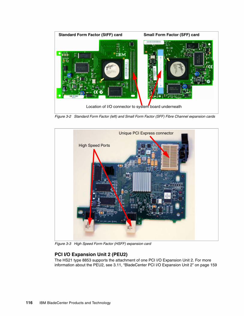
116 IBM BladeCenter Products and Technology
Figure 3-2 Standard Form Factor (left) and Small Form Factor (SFF) Fibre Channel expansion cards
Figure 3-3 High Speed Form Factor (HSFF) expansion card
PCI I/O Expansion Unit 2 (PEU2)The HS21 type 8853 supports the attachment of one PCI I/O Expansion Unit 2. For more information about the PEU2, see 3.11, “BladeCenter PCI I/O Expansion Unit 2” on page 159
Location of I/O connector to system board underneath
Standard Form Factor (StFF) card Small Form Factor (SFF) card
Unique PCI Express connector
High Speed Ports
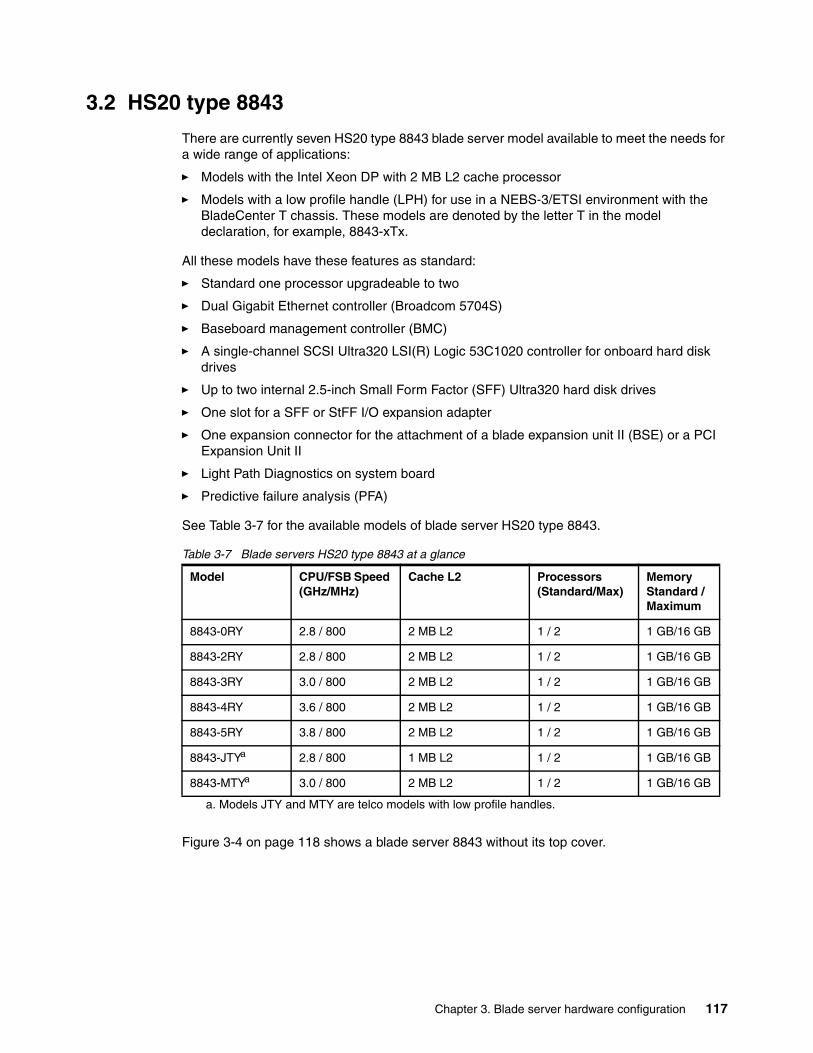
Chapter 3. Blade server hardware configuration 117
3.2 HS20 type 8843
There are currently seven HS20 type 8843 blade server model available to meet the needs for a wide range of applications:
� Models with the Intel Xeon DP with 2 MB L2 cache processor
� Models with a low profile handle (LPH) for use in a NEBS-3/ETSI environment with the BladeCenter T chassis. These models are denoted by the letter T in the model declaration, for example, 8843-xTx.
All these models have these features as standard:
� Standard one processor upgradeable to two
� Dual Gigabit Ethernet controller (Broadcom 5704S)
� Baseboard management controller (BMC)
� A single-channel SCSI Ultra320 LSI(R) Logic 53C1020 controller for onboard hard disk drives
� Up to two internal 2.5-inch Small Form Factor (SFF) Ultra320 hard disk drives
� One slot for a SFF or StFF I/O expansion adapter
� One expansion connector for the attachment of a blade expansion unit II (BSE) or a PCI Expansion Unit II
� Light Path Diagnostics on system board
� Predictive failure analysis (PFA)
See Table 3-7 for the available models of blade server HS20 type 8843.
Table 3-7 Blade servers HS20 type 8843 at a glance
Figure 3-4 on page 118 shows a blade server 8843 without its top cover.
Model CPU/FSB Speed (GHz/MHz)
Cache L2 Processors (Standard/Max)
Memory Standard / Maximum
8843-0RY 2.8 / 800 2 MB L2 1 / 2 1 GB/16 GB
8843-2RY 2.8 / 800 2 MB L2 1 / 2 1 GB/16 GB
8843-3RY 3.0 / 800 2 MB L2 1 / 2 1 GB/16 GB
8843-4RY 3.6 / 800 2 MB L2 1 / 2 1 GB/16 GB
8843-5RY 3.8 / 800 2 MB L2 1 / 2 1 GB/16 GB
8843-JTYa
a. Models JTY and MTY are telco models with low profile handles.
2.8 / 800 1 MB L2 1 / 2 1 GB/16 GB
8843-MTYa 3.0 / 800 2 MB L2 1 / 2 1 GB/16 GB
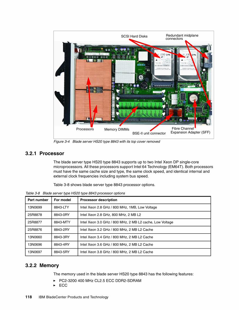
118 IBM BladeCenter Products and Technology
Figure 3-4 Blade server HS20 type 8843 with its top cover removed
3.2.1 Processor
The blade server type HS20 type 8843 supports up to two Intel Xeon DP single-core microprocessors. All these processors support Intel 64 Technology (EM64T). Both processors must have the same cache size and type, the same clock speed, and identical internal and external clock frequencies including system bus speed.
Table 3-8 shows blade server type 8843 processor options.
Table 3-8 Blade server type HS20 type 8843 processor options
3.2.2 Memory
The memory used in the blade server HS20 type 8843 has the following features:
� PC2-3200 400 MHz CL2.5 ECC DDR2-SDRAM� ECC
Processors Memory DIMMs Fibre Channel Expansion Adapter (SFF)
SCSI Hard Disks Redundant midplaneconnectors
BSE-II unit connector
Part number For model Processor description
13N0699 8843-LTY Intel Xeon 2.8 GHz / 800 MHz, 1MB, Low Voltage
25R8878 8843-0RY Intel Xeon 2.8 GHz, 800 MHz, 2 MB L2
25R8877 8843-MTY Intel Xeon 3.0 GHz / 800 MHz, 2 MB L2 cache, Low Voltage
25R8876 8843-2RY Intel Xeon 3.2 GHz / 800 MHz, 2 MB L2 Cache
13N0660 8843-3RY Intel Xeon 3.4 GHz / 800 MHz, 2 MB L2 Cache
13N0696 8843-4RY Intel Xeon 3.6 GHz / 800 MHz, 2 MB L2 Cache
13N0697 8843-5RY Intel Xeon 3.8 GHz / 800 MHz, 2 MB L2 Cache
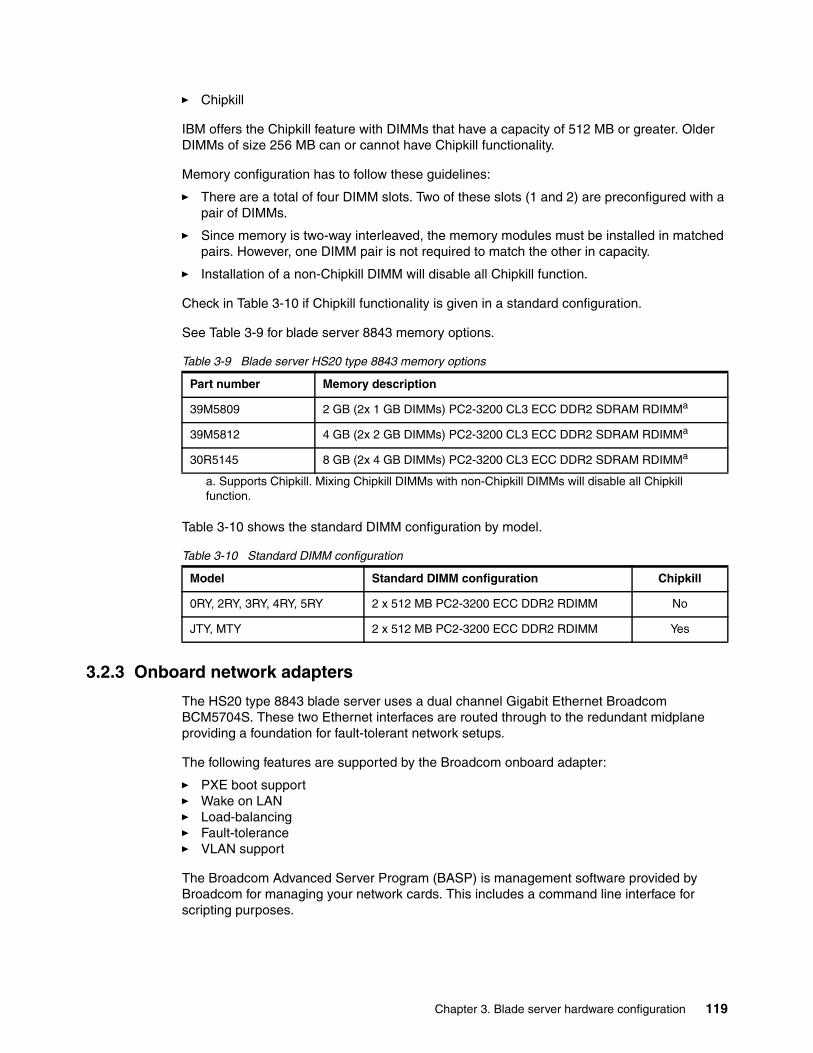
Chapter 3. Blade server hardware configuration 119
� Chipkill
IBM offers the Chipkill feature with DIMMs that have a capacity of 512 MB or greater. Older DIMMs of size 256 MB can or cannot have Chipkill functionality.
Memory configuration has to follow these guidelines:
� There are a total of four DIMM slots. Two of these slots (1 and 2) are preconfigured with a pair of DIMMs.
� Since memory is two-way interleaved, the memory modules must be installed in matched pairs. However, one DIMM pair is not required to match the other in capacity.
� Installation of a non-Chipkill DIMM will disable all Chipkill function.
Check in Table 3-10 if Chipkill functionality is given in a standard configuration.
See Table 3-9 for blade server 8843 memory options.
Table 3-9 Blade server HS20 type 8843 memory options
Table 3-10 shows the standard DIMM configuration by model.
Table 3-10 Standard DIMM configuration
3.2.3 Onboard network adapters
The HS20 type 8843 blade server uses a dual channel Gigabit Ethernet Broadcom BCM5704S. These two Ethernet interfaces are routed through to the redundant midplane providing a foundation for fault-tolerant network setups.
The following features are supported by the Broadcom onboard adapter:
� PXE boot support� Wake on LAN � Load-balancing� Fault-tolerance� VLAN support
The Broadcom Advanced Server Program (BASP) is management software provided by Broadcom for managing your network cards. This includes a command line interface for scripting purposes.
Part number Memory description
39M5809 2 GB (2x 1 GB DIMMs) PC2-3200 CL3 ECC DDR2 SDRAM RDIMMa
39M5812 4 GB (2x 2 GB DIMMs) PC2-3200 CL3 ECC DDR2 SDRAM RDIMMa
a. Supports Chipkill. Mixing Chipkill DIMMs with non-Chipkill DIMMs will disable all Chipkill function.
30R5145 8 GB (2x 4 GB DIMMs) PC2-3200 CL3 ECC DDR2 SDRAM RDIMMa
Model Standard DIMM configuration Chipkill
0RY, 2RY, 3RY, 4RY, 5RY 2 x 512 MB PC2-3200 ECC DDR2 RDIMM No
JTY, MTY 2 x 512 MB PC2-3200 ECC DDR2 RDIMM Yes
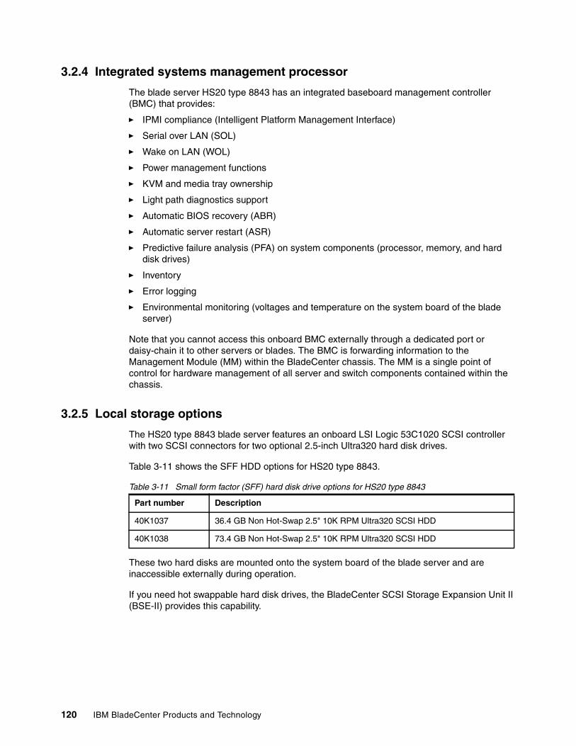
120 IBM BladeCenter Products and Technology
3.2.4 Integrated systems management processor
The blade server HS20 type 8843 has an integrated baseboard management controller (BMC) that provides:
� IPMI compliance (Intelligent Platform Management Interface)
� Serial over LAN (SOL)
� Wake on LAN (WOL)
� Power management functions
� KVM and media tray ownership
� Light path diagnostics support
� Automatic BIOS recovery (ABR)
� Automatic server restart (ASR)
� Predictive failure analysis (PFA) on system components (processor, memory, and hard disk drives)
� Inventory
� Error logging
� Environmental monitoring (voltages and temperature on the system board of the blade server)
Note that you cannot access this onboard BMC externally through a dedicated port or daisy-chain it to other servers or blades. The BMC is forwarding information to the Management Module (MM) within the BladeCenter chassis. The MM is a single point of control for hardware management of all server and switch components contained within the chassis.
3.2.5 Local storage options
The HS20 type 8843 blade server features an onboard LSI Logic 53C1020 SCSI controller with two SCSI connectors for two optional 2.5-inch Ultra320 hard disk drives.
Table 3-11 shows the SFF HDD options for HS20 type 8843.
Table 3-11 Small form factor (SFF) hard disk drive options for HS20 type 8843
These two hard disks are mounted onto the system board of the blade server and are inaccessible externally during operation.
If you need hot swappable hard disk drives, the BladeCenter SCSI Storage Expansion Unit II (BSE-II) provides this capability.
Part number Description
40K1037 36.4 GB Non Hot-Swap 2.5" 10K RPM Ultra320 SCSI HDD
40K1038 73.4 GB Non Hot-Swap 2.5" 10K RPM Ultra320 SCSI HDD
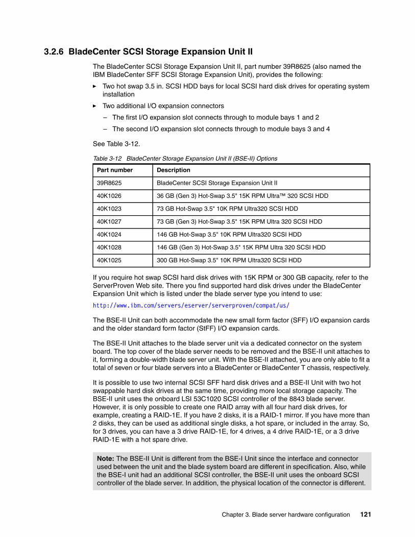
Chapter 3. Blade server hardware configuration 121
3.2.6 BladeCenter SCSI Storage Expansion Unit II
The BladeCenter SCSI Storage Expansion Unit II, part number 39R8625 (also named the IBM BladeCenter SFF SCSI Storage Expansion Unit), provides the following:
� Two hot swap 3.5 in. SCSI HDD bays for local SCSI hard disk drives for operating system installation
� Two additional I/O expansion connectors
– The first I/O expansion slot connects through to module bays 1 and 2
– The second I/O expansion slot connects through to module bays 3 and 4
See Table 3-12.
Table 3-12 BladeCenter Storage Expansion Unit II (BSE-II) Options
If you require hot swap SCSI hard disk drives with 15K RPM or 300 GB capacity, refer to the ServerProven Web site. There you find supported hard disk drives under the BladeCenter Expansion Unit which is listed under the blade server type you intend to use:
http://www.ibm.com/servers/eserver/serverproven/compat/us/
The BSE-II Unit can both accommodate the new small form factor (SFF) I/O expansion cards and the older standard form factor (StFF) I/O expansion cards.
The BSE-II Unit attaches to the blade server unit via a dedicated connector on the system board. The top cover of the blade server needs to be removed and the BSE-II unit attaches to it, forming a double-width blade server unit. With the BSE-II attached, you are only able to fit a total of seven or four blade servers into a BladeCenter or BladeCenter T chassis, respectively.
It is possible to use two internal SCSI SFF hard disk drives and a BSE-II Unit with two hot swappable hard disk drives at the same time, providing more local storage capacity. The BSE-II unit uses the onboard LSI 53C1020 SCSI controller of the 8843 blade server. However, it is only possible to create one RAID array with all four hard disk drives, for example, creating a RAID-1E. If you have 2 disks, it is a RAID-1 mirror. If you have more than 2 disks, they can be used as additional single disks, a hot spare, or included in the array. So, for 3 drives, you can have a 3 drive RAID-1E, for 4 drives, a 4 drive RAID-1E, or a 3 drive RAID-1E with a hot spare drive.
Part number Description
39R8625 BladeCenter SCSI Storage Expansion Unit II
40K1026 36 GB (Gen 3) Hot-Swap 3.5" 15K RPM Ultra™ 320 SCSI HDD
40K1023 73 GB Hot-Swap 3.5" 10K RPM Ultra320 SCSI HDD
40K1027 73 GB (Gen 3) Hot-Swap 3.5" 15K RPM Ultra 320 SCSI HDD
40K1024 146 GB Hot-Swap 3.5" 10K RPM Ultra320 SCSI HDD
40K1028 146 GB (Gen 3) Hot-Swap 3.5" 15K RPM Ultra 320 SCSI HDD
40K1025 300 GB Hot-Swap 3.5" 10K RPM Ultra320 SCSI HDD
Note: The BSE-II Unit is different from the BSE-I Unit since the interface and connector used between the unit and the blade system board are different in specification. Also, while the BSE-I unit had an additional SCSI controller, the BSE-II unit uses the onboard SCSI controller of the blade server. In addition, the physical location of the connector is different.
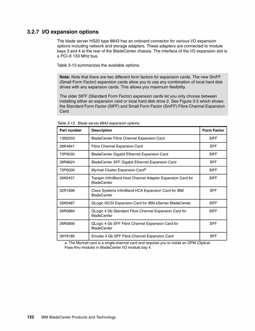
122 IBM BladeCenter Products and Technology
3.2.7 I/O expansion options
The blade server HS20 type 8843 has an onboard connector for various I/O expansion options including network and storage adapters. These adapters are connected to module bays 3 and 4 at the rear of the BladeCenter chassis. The interface of the I/O expansion slot is a PCI-X 133 MHz bus.
Table 3-13 summarizes the available options.
Table 3-13 Blade server 8843 expansion options
Note: Note that there are two different form factors for expansion cards. The new SmFF (Small Form Factor) expansion cards allow you to use any combination of local hard disk drives with any expansion cards. This allows you maximum flexibility.
The older StFF (Standard Form Factor) expansion cards let you only choose between installing either an expansion card or local hard disk drive 2. See Figure 3-5 which shows the Standard Form Factor (StFF) and Small Form Factor (SmFF) Fibre Channel Expansion Card.
Part number Description Form Factor
13N2203 BladeCenter Fibre Channel Expansion Card StFF
26K4841 Fibre Channel Expansion Card SFF
73P9030 BladeCenter Gigabit Ethernet Expansion Card StFF
39R8624 BladeCenter SFF Gigabit Ethernet Expansion Card SFF
73P6000 Myrinet Cluster Expansion Carda
a. The Myrinet card is a single-channel card and requires you to install an OPM (Optical Pass-thru module) in BladeCenter I/O module bay 4.
StFF
26K6457 Topspin InfiniBand Host Channel Adapter Expansion Card for BladeCenter
StFF
32R1896 Cisco Systems InfiniBand HCA Expansion Card for IBM BladeCenter
SFF
26K6487 QLogic iSCSI Expansion Card for IBM eServer BladeCenter StFF
26R0884 QLogic 4 Gb Standard Fibre Channel Expansion Card for BladeCenter
StFF
26R0890 QLogic 4 Gb SFF Fibre Channel Expansion Card for BladeCenter
SFF
39Y9186 Emulex 4 Gb SFF Fibre Channel Expansion Card SFF
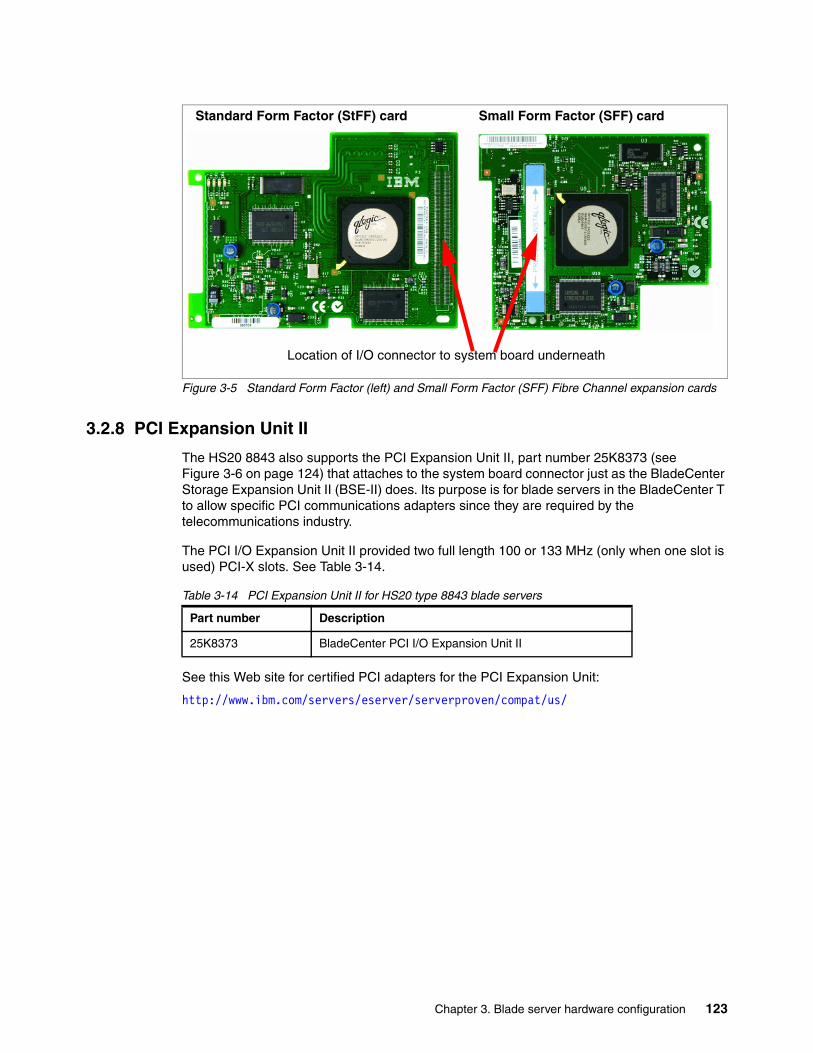
Chapter 3. Blade server hardware configuration 123
Figure 3-5 Standard Form Factor (left) and Small Form Factor (SFF) Fibre Channel expansion cards
3.2.8 PCI Expansion Unit II
The HS20 8843 also supports the PCI Expansion Unit II, part number 25K8373 (see Figure 3-6 on page 124) that attaches to the system board connector just as the BladeCenter Storage Expansion Unit II (BSE-II) does. Its purpose is for blade servers in the BladeCenter T to allow specific PCI communications adapters since they are required by the telecommunications industry.
The PCI I/O Expansion Unit II provided two full length 100 or 133 MHz (only when one slot is used) PCI-X slots. See Table 3-14.
Table 3-14 PCI Expansion Unit II for HS20 type 8843 blade servers
See this Web site for certified PCI adapters for the PCI Expansion Unit:
http://www.ibm.com/servers/eserver/serverproven/compat/us/
Location of I/O connector to system board underneath
Standard Form Factor (StFF) card Small Form Factor (SFF) card
Part number Description
25K8373 BladeCenter PCI I/O Expansion Unit II
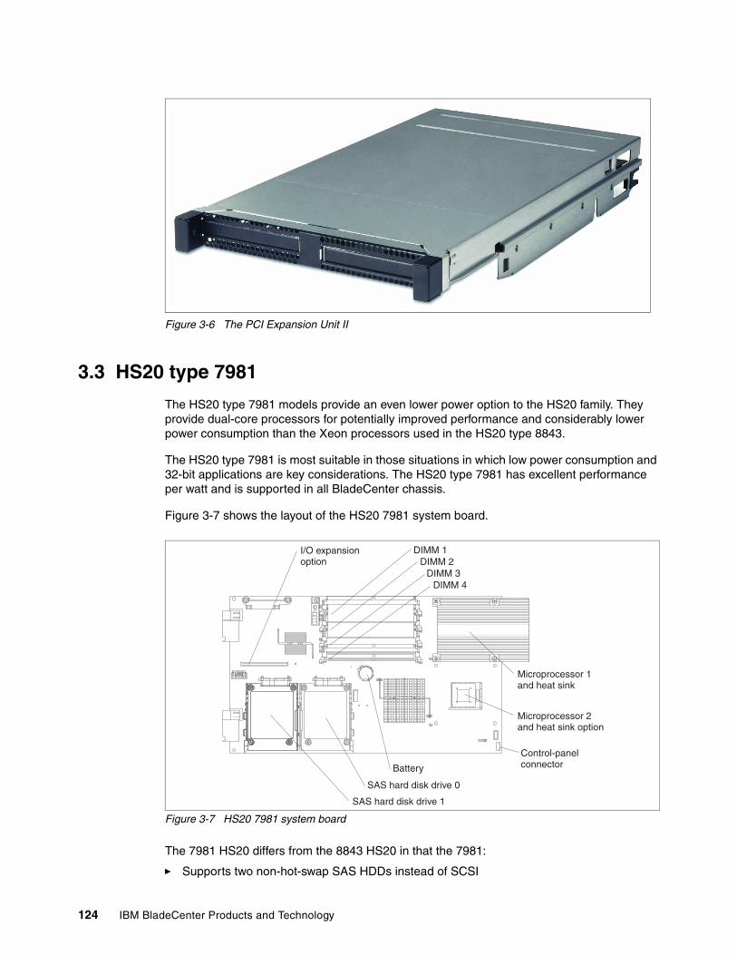
124 IBM BladeCenter Products and Technology
Figure 3-6 The PCI Expansion Unit II
3.3 HS20 type 7981
The HS20 type 7981 models provide an even lower power option to the HS20 family. They provide dual-core processors for potentially improved performance and considerably lower power consumption than the Xeon processors used in the HS20 type 8843.
The HS20 type 7981 is most suitable in those situations in which low power consumption and 32-bit applications are key considerations. The HS20 type 7981 has excellent performance per watt and is supported in all BladeCenter chassis.
Figure 3-7 shows the layout of the HS20 7981 system board.
Figure 3-7 HS20 7981 system board
The 7981 HS20 differs from the 8843 HS20 in that the 7981:
� Supports two non-hot-swap SAS HDDs instead of SCSI
Battery
SAS hard disk drive 0
SAS hard disk drive 1
Microprocessor 1and heat sink
Microprocessor 2and heat sink option
Control-panelconnector
DIMM 4DIMM 3
DIMM 2DIMM 1I/O expansion
option
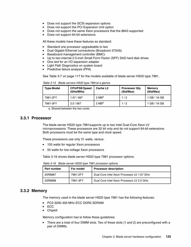
Chapter 3. Blade server hardware configuration 125
� Does not support the SCSI expansion options � Does not support the PCI Expansion Unit option� Does not support the same Xeon processors that the 8843 supported� Does not support 64-bit extensions
All these models have these features as standard:
� Standard one processor upgradeable to two� Dual Gigabit Ethernet connections (Broadcom 5704S)� Baseboard management controller (BMC)� Up to two internal 2.5-inch Small Form Factor (SFF) SAS hard disk drives� One slot for an I/O expansion adapter� Light Path Diagnostics on system board� Predictive failure analysis (PFA)
See Table 3-7 on page 117 for the models available of blade server HS20 type 7981.
Table 3-15 Blade servers HS20 type 7981at a glance
3.3.1 Processor
The blade server HS20 type 7981supports up to two Intel Dual-Core Xeon LV microprocessors. These processors are 32 bit only and do not support 64-bit extensions. Both processors must be the same type and clock speed.
These processors use only 31 watts, versus:
� 105 watts for regular Xeon processors
� 55 watts for low-voltage Xeon processors
Table 3-16 shows blade server HS20 type 7981 processor options.
Table 3-16 Blade server HS20 type 7981 processor options
3.3.2 Memory
The memory used in the blade server HS20 type 7981 has the following features:
� PC2-3200 400 MHz ECC DDR2 SDRAM� ECC� Chipkill
Memory configuration has to follow these guidelines:
� There are a total of four DIMM slots. Two of these slots (1 and 2) are preconfigured with a pair of DIMMs.
Type-Model CPU/FSB Speed (GHz/MHz)
Cache L2 Processor Qty (Std/Max)
Memory (Std/Max)
7981-2FY 1.67 / 667 2 MBa
a. Shared between the two cores
1 / 2 1 GB / 16 GB
7981-3FY 2.0 / 667 2 MBa 1 / 2 1 GB / 16 GB
Part number For model Processor description
25R8887 7981-2FY Dual Core Intel Xeon Processor LV 1.67 GHz
25R8888 7981-3FY Dual Core Intel Xeon Processor LV 2.0 GHz
126 IBM BladeCenter Products and Technology
� Since memory is two-way interleaved, the memory modules must be installed in matched pairs. Installation of a non-Chipkill DIMM will disable all Chipkill function.
� Memory is available with the Chipkill feature with DIMMs that have a capacity of 1 GB or greater.
Check in Table 3-18 if Chipkill functionality is given in a standard configuration.
See Table 3-17 for blade server HS20 type 7981 memory options.
Table 3-17 Blade server HS20 type 7981 memory options
Table 3-18 shows the standard DIMM configuration by model.
Table 3-18 Standard DIMM configuration
3.3.3 Onboard network adapters
The HS20 type 7981 blade server uses a dual channel Gigabit Ethernet Broadcom BCM5704S. These two Ethernet interfaces are routed through to the redundant midplane providing a foundation for fault-tolerant network setups.
The following features are supported by the Broadcom onboard adapter:
� PXE 2.0 Boot Agent� Wake on LAN � Load balancing or teaming� Failover, adapter fault tolerance
The Broadcom Advanced Server Program (BASP) is management software provided by Broadcom for managing your network cards. This includes a command line interface for scripting purposes.
3.3.4 Integrated systems management processor
The blade server HS20 type 7981 has an integrated baseboard management controller (BMC) that provides:
� IPMI compliance (Intelligent Platform Management Interface)
� Serial over LAN (SOL)
� Wake on LAN (WOL)
� Power management functions
� KVM and media tray ownership
� Light path diagnostics support
� Automatic server restart (ASR)
Part number Memory description
39M5809 2 GB (2 x 1 GB kit) PC2-3200 CL3 ECC DDR2 SDRAM RDIMM
39M5812 4 GB (2 x 2 GB kit) PC2-3200 CL3 ECC DDR2 SDRAM RDIMM
30R5145 8 GB (2 x 4 GB kit) PC2-3200 CL3 ECC DDR2 SDRAM RDIMM
Model Standard DIMM configuration Chipkill
2FY, 3FY 2 x 512MB PC2-3200 ECC DDR2 SDRAM RDIMM No
Chapter 3. Blade server hardware configuration 127
� Predictive failure analysis (PFA) on system components (processor, memory, and hard disk drives)
� Inventory
� Error logging
� Environmental monitoring (voltages and temperature on the system board of the blade server)
Note that you cannot access this onboard BMC externally through a dedicated port or daisy-chain it to other servers or blades. The BMC is forwarding information to the Management Module (MM) within the BladeCenter chassis. The MM is a single point of control for hardware management of all server and switch components contained within the chassis.
3.3.5 Local storage options
The HS20 type 7981 blade server features an onboard LSI Logic 1064 SAS controller with two connectors for up to two optional 2.5-inch Small Form Factor (SFF) SAS hard disk drives. The LSI controller also provides RAID 0 or RAID 1 support.
Table 3-19 shows the SFF HDD options for HS20 type 7981.
Table 3-19 Small form factor (SFF) hard disk drive options for HS20 type 7981
These two hard disks are mounted onto the system board of the blade server and are inaccessible from the outside during operation.
3.3.6 I/O expansion options
The blade server HS20 type 7981 has an onboard connector for various I/O expansion options including network and storage adapters. These adapters are connected to module bays 3 and 4 at the rear of the BladeCenter chassis. The interface of the I/O expansion slot is a PCI-X 133 MHz bus.
Table 3-20 on page 128 summarizes the available options.
Part number Description
26K5776 36.4 GB SAS HDD (2.5”) SFF
26K5777 73.4 GB SAS HDD (2.5”) SFF
Note: The HS20 type 7981 does not support the attachment of any of the BladeCenter storage expansion units.
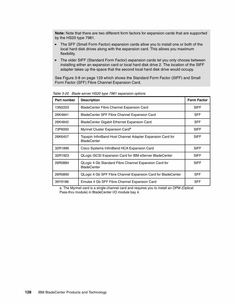
128 IBM BladeCenter Products and Technology
Table 3-20 Blade server HS20 type 7981 expansion options
Note: Note that there are two different form factors for expansion cards that are supported by the HS20 type 7981.
� The SFF (Small Form Factor) expansion cards allow you to install one or both of the local hard disk drives along with the expansion card. This allows you maximum flexibility.
� The older StFF (Standard Form Factor) expansion cards let you only choose between installing either an expansion card or local hard disk drive 2. The location of the StFF adapter takes up the space that the second local hard disk drive would occupy.
See Figure 3-8 on page 129 which shows the Standard Form Factor (StFF) and Small Form Factor (SFF) Fibre Channel Expansion Card.
Part number Description Form Factor
13N2203 BladeCenter Fibre Channel Expansion Card StFF
26K4841 BladeCenter SFF Fibre Channel Expansion Card SFF
26K4842 BladeCenter Gigabit Ethernet Expansion Card SFF
73P6000 Myrinet Cluster Expansion Carda
a. The Myrinet card is a single-channel card and requires you to install an OPM (Optical Pass-thru module) in BladeCenter I/O module bay 4.
StFF
26K6457 Topspin InfiniBand Host Channel Adapter Expansion Card for BladeCenter
StFF
32R1896 Cisco Systems InfiniBand HCA Expansion Card StFF
32R1923 QLogic iSCSI Expansion Card for IBM eServer BladeCenter StFF
26R0884 QLogic 4 Gb Standard Fibre Channel Expansion Card for BladeCenter
StFF
26R0890 QLogic 4 Gb SFF Fibre Channel Expansion Card for BladeCenter SFF
39Y9186 Emulex 4 Gb SFF Fibre Channel Expansion Card SFF
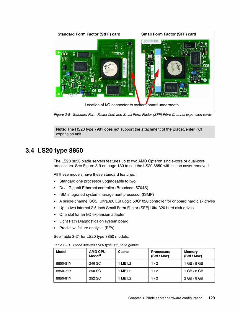
Chapter 3. Blade server hardware configuration 129
Figure 3-8 Standard Form Factor (left) and Small Form Factor (SFF) Fibre Channel expansion cards
3.4 LS20 type 8850
The LS20 8850 blade servers features up to two AMD Opteron single-core or dual-core processors. See Figure 3-9 on page 130 to see the LS20 8850 with its top cover removed.
All these models have these standard features:
� Standard one processor upgradeable to two
� Dual Gigabit Ethernet controller (Broadcom 5704S)
� IBM integrated system management processor (ISMP)
� A single-channel SCSI Ultra320 LSI Logic 53C1020 controller for onboard hard disk drives
� Up to two internal 2.5-inch Small Form Factor (SFF) Ultra320 hard disk drives
� One slot for an I/O expansion adapter
� Light Path Diagnostics on system board
� Predictive failure analysis (PFA)
See Table 3-21 for LS20 type 8850 models.
Table 3-21 Blade servers LS20 type 8850 at a glance
Note: The HS20 type 7981 does not support the attachment of the BladeCenter PCI expansion unit.
Location of I/O connector to system board underneath
Standard Form Factor (StFF) card Small Form Factor (SFF) card
Model AMD CPU Modela
Cache Processors(Std / Max)
Memory(Std / Max)
8850-51Y 246 SC 1 MB L2 1 / 2 1 GB / 8 GB
8850-71Y 250 SC 1 MB L2 1 / 2 1 GB / 8 GB
8850-81Y 252 SC 1 MB L2 1 / 2 2 GB / 8 GB
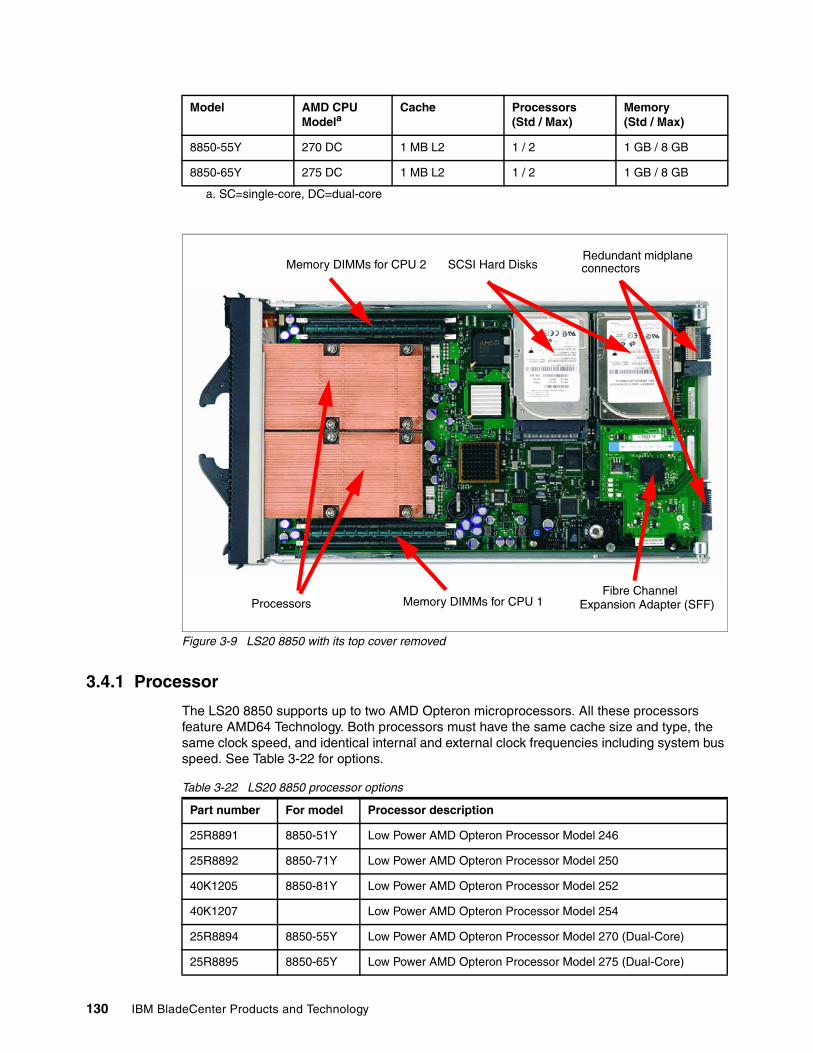
130 IBM BladeCenter Products and Technology
Figure 3-9 LS20 8850 with its top cover removed
3.4.1 Processor
The LS20 8850 supports up to two AMD Opteron microprocessors. All these processors feature AMD64 Technology. Both processors must have the same cache size and type, the same clock speed, and identical internal and external clock frequencies including system bus speed. See Table 3-22 for options.
Table 3-22 LS20 8850 processor options
8850-55Y 270 DC 1 MB L2 1 / 2 1 GB / 8 GB
8850-65Y 275 DC 1 MB L2 1 / 2 1 GB / 8 GB
a. SC=single-core, DC=dual-core
Model AMD CPU Modela
Cache Processors(Std / Max)
Memory(Std / Max)
Processors
Memory DIMMs for CPU 2 SCSI Hard DisksRedundant midplaneconnectors
Memory DIMMs for CPU 1Fibre Channel
Expansion Adapter (SFF)
Part number For model Processor description
25R8891 8850-51Y Low Power AMD Opteron Processor Model 246
25R8892 8850-71Y Low Power AMD Opteron Processor Model 250
40K1205 8850-81Y Low Power AMD Opteron Processor Model 252
40K1207 Low Power AMD Opteron Processor Model 254
25R8894 8850-55Y Low Power AMD Opteron Processor Model 270 (Dual-Core)
25R8895 8850-65Y Low Power AMD Opteron Processor Model 275 (Dual-Core)
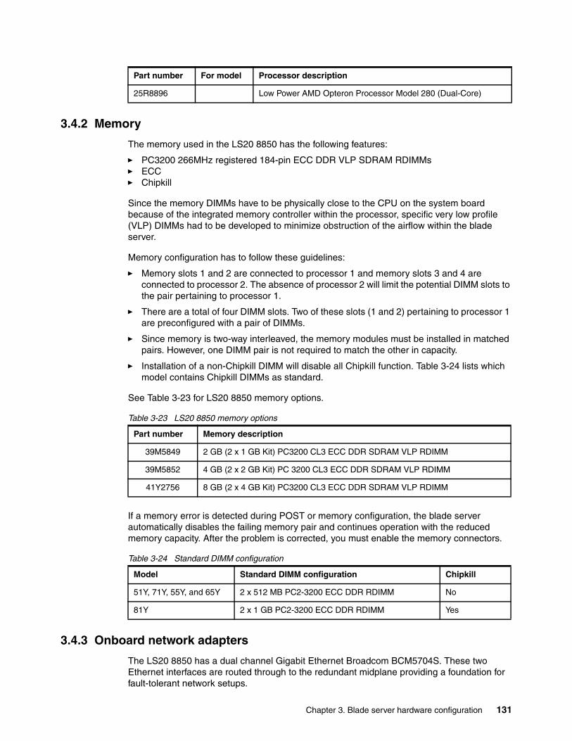
Chapter 3. Blade server hardware configuration 131
3.4.2 Memory
The memory used in the LS20 8850 has the following features:
� PC3200 266MHz registered 184-pin ECC DDR VLP SDRAM RDIMMs� ECC� Chipkill
Since the memory DIMMs have to be physically close to the CPU on the system board because of the integrated memory controller within the processor, specific very low profile (VLP) DIMMs had to be developed to minimize obstruction of the airflow within the blade server.
Memory configuration has to follow these guidelines:
� Memory slots 1 and 2 are connected to processor 1 and memory slots 3 and 4 are connected to processor 2. The absence of processor 2 will limit the potential DIMM slots to the pair pertaining to processor 1.
� There are a total of four DIMM slots. Two of these slots (1 and 2) pertaining to processor 1 are preconfigured with a pair of DIMMs.
� Since memory is two-way interleaved, the memory modules must be installed in matched pairs. However, one DIMM pair is not required to match the other in capacity.
� Installation of a non-Chipkill DIMM will disable all Chipkill function. Table 3-24 lists which model contains Chipkill DIMMs as standard.
See Table 3-23 for LS20 8850 memory options.
Table 3-23 LS20 8850 memory options
If a memory error is detected during POST or memory configuration, the blade server automatically disables the failing memory pair and continues operation with the reduced memory capacity. After the problem is corrected, you must enable the memory connectors.
Table 3-24 Standard DIMM configuration
3.4.3 Onboard network adapters
The LS20 8850 has a dual channel Gigabit Ethernet Broadcom BCM5704S. These two Ethernet interfaces are routed through to the redundant midplane providing a foundation for fault-tolerant network setups.
25R8896 Low Power AMD Opteron Processor Model 280 (Dual-Core)
Part number For model Processor description
Part number Memory description
39M5849 2 GB (2 x 1 GB Kit) PC3200 CL3 ECC DDR SDRAM VLP RDIMM
39M5852 4 GB (2 x 2 GB Kit) PC 3200 CL3 ECC DDR SDRAM VLP RDIMM
41Y2756 8 GB (2 x 4 GB Kit) PC3200 CL3 ECC DDR SDRAM VLP RDIMM
Model Standard DIMM configuration Chipkill
51Y, 71Y, 55Y, and 65Y 2 x 512 MB PC2-3200 ECC DDR RDIMM No
81Y 2 x 1 GB PC2-3200 ECC DDR RDIMM Yes
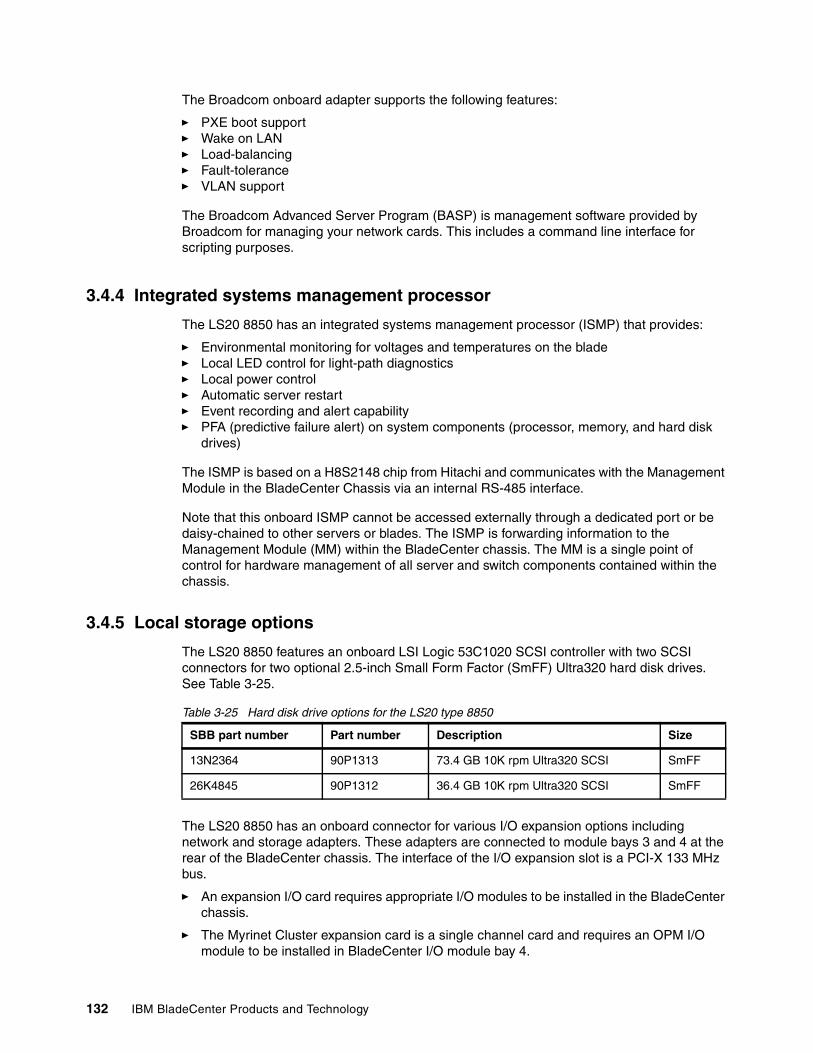
132 IBM BladeCenter Products and Technology
The Broadcom onboard adapter supports the following features:
� PXE boot support� Wake on LAN � Load-balancing� Fault-tolerance� VLAN support
The Broadcom Advanced Server Program (BASP) is management software provided by Broadcom for managing your network cards. This includes a command line interface for scripting purposes.
3.4.4 Integrated systems management processor
The LS20 8850 has an integrated systems management processor (ISMP) that provides:
� Environmental monitoring for voltages and temperatures on the blade� Local LED control for light-path diagnostics� Local power control� Automatic server restart� Event recording and alert capability� PFA (predictive failure alert) on system components (processor, memory, and hard disk
drives)
The ISMP is based on a H8S2148 chip from Hitachi and communicates with the Management Module in the BladeCenter Chassis via an internal RS-485 interface.
Note that this onboard ISMP cannot be accessed externally through a dedicated port or be daisy-chained to other servers or blades. The ISMP is forwarding information to the Management Module (MM) within the BladeCenter chassis. The MM is a single point of control for hardware management of all server and switch components contained within the chassis.
3.4.5 Local storage options
The LS20 8850 features an onboard LSI Logic 53C1020 SCSI controller with two SCSI connectors for two optional 2.5-inch Small Form Factor (SmFF) Ultra320 hard disk drives. See Table 3-25.
Table 3-25 Hard disk drive options for the LS20 type 8850
The LS20 8850 has an onboard connector for various I/O expansion options including network and storage adapters. These adapters are connected to module bays 3 and 4 at the rear of the BladeCenter chassis. The interface of the I/O expansion slot is a PCI-X 133 MHz bus.
� An expansion I/O card requires appropriate I/O modules to be installed in the BladeCenter chassis.
� The Myrinet Cluster expansion card is a single channel card and requires an OPM I/O module to be installed in BladeCenter I/O module bay 4.
SBB part number Part number Description Size
13N2364 90P1313 73.4 GB 10K rpm Ultra320 SCSI SmFF
26K4845 90P1312 36.4 GB 10K rpm Ultra320 SCSI SmFF
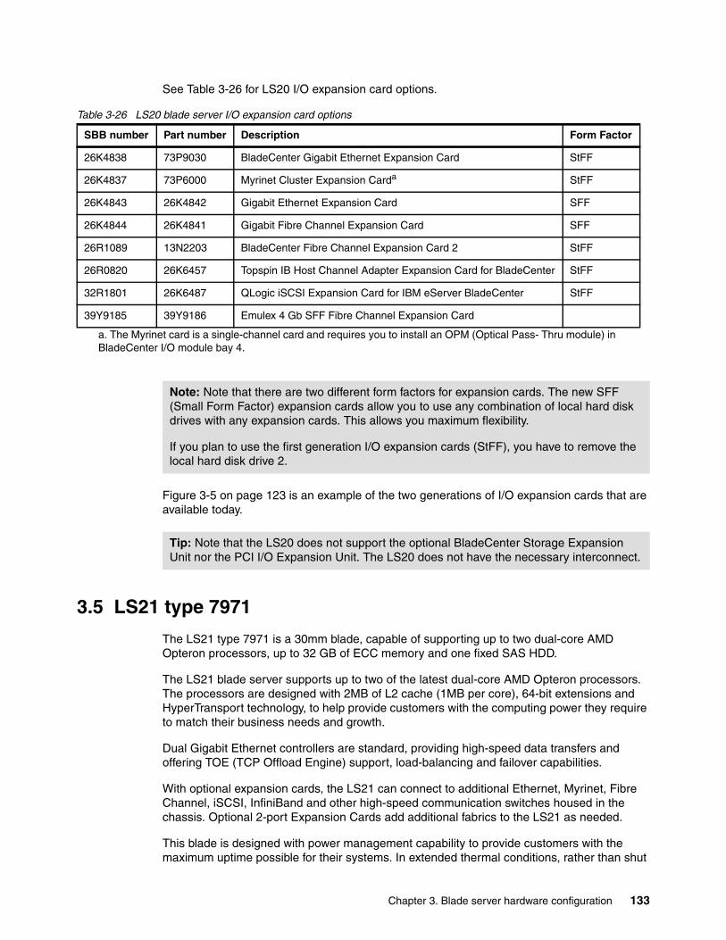
Chapter 3. Blade server hardware configuration 133
See Table 3-26 for LS20 I/O expansion card options.
Table 3-26 LS20 blade server I/O expansion card options
Figure 3-5 on page 123 is an example of the two generations of I/O expansion cards that are available today.
3.5 LS21 type 7971
The LS21 type 7971 is a 30mm blade, capable of supporting up to two dual-core AMD Opteron processors, up to 32 GB of ECC memory and one fixed SAS HDD.
The LS21 blade server supports up to two of the latest dual-core AMD Opteron processors. The processors are designed with 2MB of L2 cache (1MB per core), 64-bit extensions and HyperTransport technology, to help provide customers with the computing power they require to match their business needs and growth.
Dual Gigabit Ethernet controllers are standard, providing high-speed data transfers and offering TOE (TCP Offload Engine) support, load-balancing and failover capabilities.
With optional expansion cards, the LS21 can connect to additional Ethernet, Myrinet, Fibre Channel, iSCSI, InfiniBand and other high-speed communication switches housed in the chassis. Optional 2-port Expansion Cards add additional fabrics to the LS21 as needed.
This blade is designed with power management capability to provide customers with the maximum uptime possible for their systems. In extended thermal conditions, rather than shut
SBB number Part number Description Form Factor
26K4838 73P9030 BladeCenter Gigabit Ethernet Expansion Card StFF
26K4837 73P6000 Myrinet Cluster Expansion Carda
a. The Myrinet card is a single-channel card and requires you to install an OPM (Optical Pass- Thru module) in BladeCenter I/O module bay 4.
StFF
26K4843 26K4842 Gigabit Ethernet Expansion Card SFF
26K4844 26K4841 Gigabit Fibre Channel Expansion Card SFF
26R1089 13N2203 BladeCenter Fibre Channel Expansion Card 2 StFF
26R0820 26K6457 Topspin IB Host Channel Adapter Expansion Card for BladeCenter StFF
32R1801 26K6487 QLogic iSCSI Expansion Card for IBM eServer BladeCenter StFF
39Y9185 39Y9186 Emulex 4 Gb SFF Fibre Channel Expansion Card
Note: Note that there are two different form factors for expansion cards. The new SFF (Small Form Factor) expansion cards allow you to use any combination of local hard disk drives with any expansion cards. This allows you maximum flexibility.
If you plan to use the first generation I/O expansion cards (StFF), you have to remove the local hard disk drive 2.
Tip: Note that the LS20 does not support the optional BladeCenter Storage Expansion Unit nor the PCI I/O Expansion Unit. The LS20 does not have the necessary interconnect.
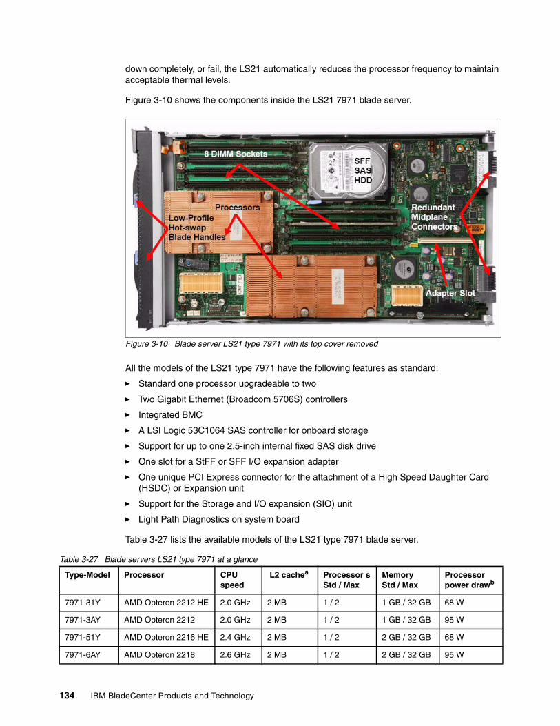
134 IBM BladeCenter Products and Technology
down completely, or fail, the LS21 automatically reduces the processor frequency to maintain acceptable thermal levels.
Figure 3-10 shows the components inside the LS21 7971 blade server.
Figure 3-10 Blade server LS21 type 7971 with its top cover removed
All the models of the LS21 type 7971 have the following features as standard:
� Standard one processor upgradeable to two
� Two Gigabit Ethernet (Broadcom 5706S) controllers
� Integrated BMC
� A LSI Logic 53C1064 SAS controller for onboard storage
� Support for up to one 2.5-inch internal fixed SAS disk drive
� One slot for a StFF or SFF I/O expansion adapter
� One unique PCI Express connector for the attachment of a High Speed Daughter Card (HSDC) or Expansion unit
� Support for the Storage and I/O expansion (SIO) unit
� Light Path Diagnostics on system board
Table 3-27 lists the available models of the LS21 type 7971 blade server.
Table 3-27 Blade servers LS21 type 7971 at a glance
Type-Model Processor CPU speed
L2 cachea Processor sStd / Max
Memory Std / Max
Processor power drawb
7971-31Y AMD Opteron 2212 HE 2.0 GHz 2 MB 1 / 2 1 GB / 32 GB 68 W
7971-3AY AMD Opteron 2212 2.0 GHz 2 MB 1 / 2 1 GB / 32 GB 95 W
7971-51Y AMD Opteron 2216 HE 2.4 GHz 2 MB 1 / 2 2 GB / 32 GB 68 W
7971-6AY AMD Opteron 2218 2.6 GHz 2 MB 1 / 2 2 GB / 32 GB 95 W
Chapter 3. Blade server hardware configuration 135
3.5.1 Processor
The LS21 7971 supports up to two AMD Opteron 2000 series dual-core processors, which contain two complete processor cores, each with its own 1 MB L2 cache. The two cores appear to software as two physical processors. These processors also support 64-bit extensions and HyperTransport technology.
Table 3-28 shows blade server LS21 type 7971 processor options.
Table 3-28 Blade server LS21 type 7971 processor options
When installing two processors, they must be identical (same clock rate, cache size and the same number of cores).
3.5.2 Memory
The memory used in the LS21 has the following features:
� PC2-5300 (667 MHz) DDR2 RDIMM (for DIMM sizes of 512 MB to 2 GB)� PC2-4200 (533 MHz) DDR2 memory (for DIMMs of size 4 GB each)� ECC� Very Low Profile (VLP)� Chipkill
Memory configuration has to follow these guidelines:
� There are a total of eight DIMM slots (four per processor socket). Two of these slots (1 and 2) are preconfigured with a pair of DIMMs.
� Since memory is two-way interleaved, the memory modules must be installed in matched pairs. However, one DIMM pair is not required to match the other in capacity.
� The maximum of 32 GB of installed memory is achieved when all DIMM sockets are populated with the 4 GB DIMMs.
For each installed microprocessor, a set of 4 DIMM sockets are enabled. See Table 3-29 on page 135 for more information.
Table 3-29 Enabled DIMM sockets
a. 1 MB per coreb. Versions of the LS21 that use the 95 W processors (LS21 - 3AY, 6AY) are designed for use in the BladeCenter H chassis. Due to increased power and thermal needs, these 95 W versions will run at 'n-2' processor speed in the BladeCenter and BladeCenter T chassis. In most cases this represents a speed reduction of 400 MHz. The versions of the LS21 that use the High Efficiency (HE) 68 W processors (LS21 - 31Y, 51Y) will run at full speed in all BladeCenter chassis.
Part number Processor description
25R8898 AMD Opteron Dual Core Processor Model 2212 HE 2.0 GHz, 1MB L2 Cache, 68w
25R8931 AMD Opteron Dual Core Processor Model 2212 2.0 GHz, 1MB L2 Cache, 95w
25R8899 AMD Opteron Dual Core Processor Model 2216 HE 2.4 GHz, 1MB L2 Cache, 68w
25R8897 AMD Opteron Dual Core Processor Model 2218 2.6 GHz, 1MB L2 Cache, 95w
Installed Microprocessors Enabled DIMM sockets
1 1, 2, 3, 4
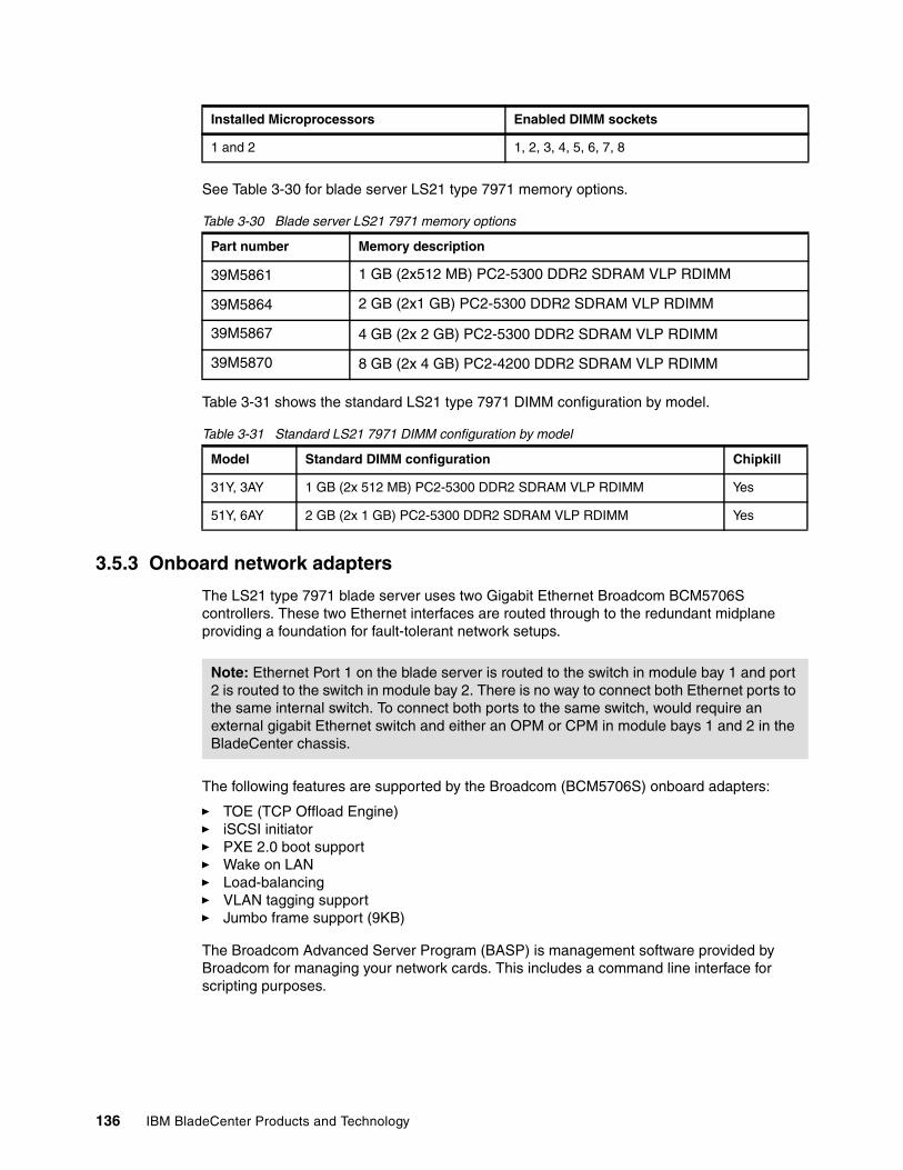
136 IBM BladeCenter Products and Technology
See Table 3-30 for blade server LS21 type 7971 memory options.
Table 3-30 Blade server LS21 7971 memory options
Table 3-31 shows the standard LS21 type 7971 DIMM configuration by model.
Table 3-31 Standard LS21 7971 DIMM configuration by model
3.5.3 Onboard network adapters
The LS21 type 7971 blade server uses two Gigabit Ethernet Broadcom BCM5706S controllers. These two Ethernet interfaces are routed through to the redundant midplane providing a foundation for fault-tolerant network setups.
The following features are supported by the Broadcom (BCM5706S) onboard adapters:
� TOE (TCP Offload Engine)� iSCSI initiator� PXE 2.0 boot support� Wake on LAN � Load-balancing� VLAN tagging support� Jumbo frame support (9KB)
The Broadcom Advanced Server Program (BASP) is management software provided by Broadcom for managing your network cards. This includes a command line interface for scripting purposes.
1 and 2 1, 2, 3, 4, 5, 6, 7, 8
Part number Memory description
39M5861 1 GB (2x512 MB) PC2-5300 DDR2 SDRAM VLP RDIMM
39M5864 2 GB (2x1 GB) PC2-5300 DDR2 SDRAM VLP RDIMM
39M5867 4 GB (2x 2 GB) PC2-5300 DDR2 SDRAM VLP RDIMM
39M5870 8 GB (2x 4 GB) PC2-4200 DDR2 SDRAM VLP RDIMM
Model Standard DIMM configuration Chipkill
31Y, 3AY 1 GB (2x 512 MB) PC2-5300 DDR2 SDRAM VLP RDIMM Yes
51Y, 6AY 2 GB (2x 1 GB) PC2-5300 DDR2 SDRAM VLP RDIMM Yes
Installed Microprocessors Enabled DIMM sockets
Note: Ethernet Port 1 on the blade server is routed to the switch in module bay 1 and port 2 is routed to the switch in module bay 2. There is no way to connect both Ethernet ports to the same internal switch. To connect both ports to the same switch, would require an external gigabit Ethernet switch and either an OPM or CPM in module bays 1 and 2 in the BladeCenter chassis.
Chapter 3. Blade server hardware configuration 137
3.5.4 Integrated systems management processor
The LS21 type 7971 has an integrated baseboard management controller (BMC) that provides:
� IPMI compliance (Intelligent Platform Management Interface)� Serial over LAN (SOL) � Wake on LAN (WOL) � Power management functions� KVM and media tray ownership� Light path diagnostics support� Automatic BIOS recovery (ABR)� Automatic server restart (ASR)� Predictive failure analysis (PFA) on system components (CPU, memory, and disk drives)� Inventory� Error logging� Environmental monitoring (voltages and temperature on the system board)
Note that you cannot access this onboard BMC externally through a dedicated port or daisy-chain it to other servers or blades. The BMC is forwarding information to the Management Module (MM) within the BladeCenter chassis. The MM is a single point of control for hardware management of all server and switch components contained within the chassis.
3.5.5 Local storage options
The LS21 type 7971 blade server features an onboard LSI Logic 53C1064 SAS controller with a SAS connector for one optional 2.5-inch Small Form Factor (SFF) SAS hard disk drive.
Table 3-5 on page 114 shows the SFF HDD options for LS21 type 7971.
Table 3-32 Small form factor (SFF) hard disk drive options for LS21 type 7971
The hard disk drive is mounted onto the system board of the blade server and are inaccessible from the outside during operation.
BladeCenter Storage and I/O Expansion Unit (SIO)The LS21 type 7971 supports the attachment of one BladeCenter Storage and I/O expansion unit. For more information about the SIO, see 3.10, “BladeCenter Storage and I/O Expansion Unit” on page 156
3.5.6 I/O expansion options
The LS21 type 7971 has an onboard connector for various I/O expansion options including network and storage adapters. These adapters are connected to module bays 3 and 4 at the rear of the BladeCenter chassis. The interface of the I/O expansion slot is a PCI-X 133 MHz bus.
Part number Description
26K5776 36.4 GB SAS HDD (2.5") SFF
26K5777 73 GB SAS HDD (2.5") SFF
Note: The LS21 type 7971 does not support the attachment of any of the previous BSE-I or BSE-II expansion units.
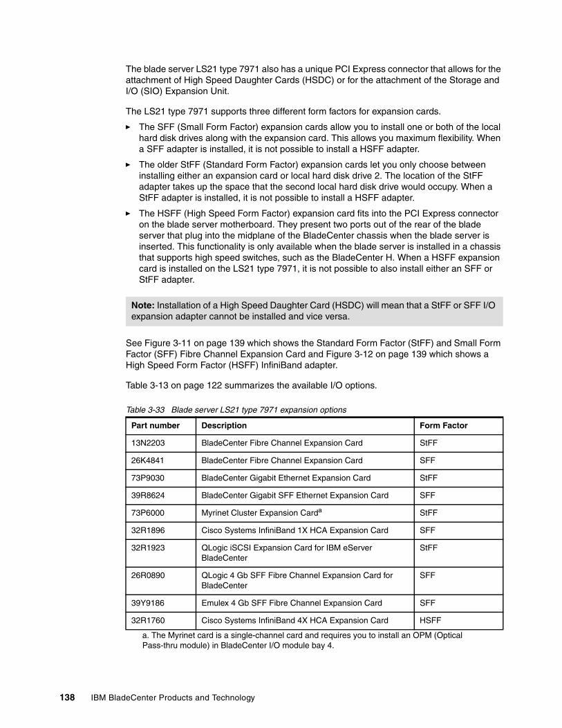
138 IBM BladeCenter Products and Technology
The blade server LS21 type 7971 also has a unique PCI Express connector that allows for the attachment of High Speed Daughter Cards (HSDC) or for the attachment of the Storage and I/O (SIO) Expansion Unit.
The LS21 type 7971 supports three different form factors for expansion cards.
� The SFF (Small Form Factor) expansion cards allow you to install one or both of the local hard disk drives along with the expansion card. This allows you maximum flexibility. When a SFF adapter is installed, it is not possible to install a HSFF adapter.
� The older StFF (Standard Form Factor) expansion cards let you only choose between installing either an expansion card or local hard disk drive 2. The location of the StFF adapter takes up the space that the second local hard disk drive would occupy. When a StFF adapter is installed, it is not possible to install a HSFF adapter.
� The HSFF (High Speed Form Factor) expansion card fits into the PCI Express connector on the blade server motherboard. They present two ports out of the rear of the blade server that plug into the midplane of the BladeCenter chassis when the blade server is inserted. This functionality is only available when the blade server is installed in a chassis that supports high speed switches, such as the BladeCenter H. When a HSFF expansion card is installed on the LS21 type 7971, it is not possible to also install either an SFF or StFF adapter.
See Figure 3-11 on page 139 which shows the Standard Form Factor (StFF) and Small Form Factor (SFF) Fibre Channel Expansion Card and Figure 3-12 on page 139 which shows a High Speed Form Factor (HSFF) InfiniBand adapter.
Table 3-13 on page 122 summarizes the available I/O options.
Table 3-33 Blade server LS21 type 7971 expansion options
Note: Installation of a High Speed Daughter Card (HSDC) will mean that a StFF or SFF I/O expansion adapter cannot be installed and vice versa.
Part number Description Form Factor
13N2203 BladeCenter Fibre Channel Expansion Card StFF
26K4841 BladeCenter Fibre Channel Expansion Card SFF
73P9030 BladeCenter Gigabit Ethernet Expansion Card StFF
39R8624 BladeCenter Gigabit SFF Ethernet Expansion Card SFF
73P6000 Myrinet Cluster Expansion Carda
a. The Myrinet card is a single-channel card and requires you to install an OPM (Optical Pass-thru module) in BladeCenter I/O module bay 4.
StFF
32R1896 Cisco Systems InfiniBand 1X HCA Expansion Card SFF
32R1923 QLogic iSCSI Expansion Card for IBM eServer BladeCenter
StFF
26R0890 QLogic 4 Gb SFF Fibre Channel Expansion Card for BladeCenter
SFF
39Y9186 Emulex 4 Gb SFF Fibre Channel Expansion Card SFF
32R1760 Cisco Systems InfiniBand 4X HCA Expansion Card HSFF
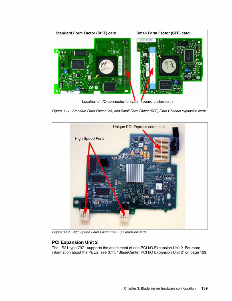
Chapter 3. Blade server hardware configuration 139
Figure 3-11 Standard Form Factor (left) and Small Form Factor (SFF) Fibre Channel expansion cards
Figure 3-12 High Speed Form Factor (HSFF) expansion card
PCI Expansion Unit 2The LS21 type 7971 supports the attachment of one PCI I/O Expansion Unit 2. For more information about the PEU2, see 3.11, “BladeCenter PCI I/O Expansion Unit 2” on page 159.
Location of I/O connector to system board underneath
Standard Form Factor (StFF) card Small Form Factor (SFF) card
Unique PCI Express connector
High Speed Ports
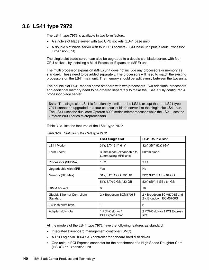
140 IBM BladeCenter Products and Technology
3.6 LS41 type 7972
The LS41 type 7972 is available in two form factors:
� A single slot blade server with two CPU sockets (LS41 base unit)
� A double slot blade server with four CPU sockets (LS41 base unit plus a Multi Processor Expansion unit)
The single slot blade server can also be upgraded to a double slot blade server, with four CPU sockets, by installing a Multi Processor Expansion (MPE) unit.
The multi processor expansion (MPE) unit does not include any processors or memory as standard. These need to be added separately. The processors will need to match the existing processors on the LS41 main unit. The memory should be split evenly between the two units.
The double slot LS41 models come standard with two processors. Two additional processors and additional memory need to be ordered separately to make the LS41 a fully configured 4 processor blade server.
Table 3-34 lists the features of the LS41 type 7972.
Table 3-34 Features of the LS41 type 7972
All the models of the LS41 type 7972 have the following features as standard:
� Integrated Baseboard management controller (BMC)
� A LSI Logic 53C1064 SAS controller for onboard hard disk drives
� One unique PCI Express connector for the attachment of a High Speed Daughter Card (HSDC) or Expansion unit
Note: The single slot LS41 is functionally similar to the LS21, except that the LS21 type 7971 cannot be upgraded to a four cpu socket blade server like the single slot LS41 can. The LS41 uses the dual core Opteron 8000 series microprocessor while the LS21 uses the Opteron 2000 series microprocessors.
LS41 Single Slot LS41 Double Slot
LS41 Model 31Y, 3AY, 51Y, 61Y 32Y, 3BY, 52Y, 6BY
Form Factor 30mm blade (expandable to 60mm using MPE unit)
60mm blade
Processors (Std/Max) 1 / 2 2 / 4
Upgradeable with MPE Yes No
Memory (Std/Max) 31Y, 3AY: 1 GB / 32 GB 32Y, 3BY: 3 GB / 64 GB
51Y, 6AY: 2 GB / 32 GB 52Y, 6BY: 4 GB / 64 GB
DIMM sockets 8 16
Gigabit Ethernet Controllers Standard
2 x Broadcom BCM5706S 2 x Broadcom BCM5706S and 2 x Broadcom BCM5708S
2.5-inch drive bays 1 2
Adapter slots total 1 PCI-X slot or 1 PCI Express slot
2 PCI-X slots or 1 PCI Express slot
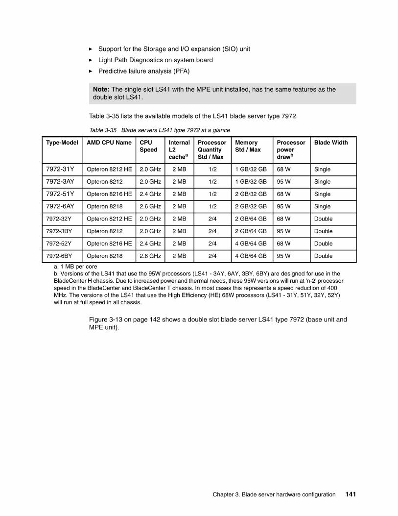
Chapter 3. Blade server hardware configuration 141
� Support for the Storage and I/O expansion (SIO) unit
� Light Path Diagnostics on system board
� Predictive failure analysis (PFA)
Table 3-35 lists the available models of the LS41 blade server type 7972.
Table 3-35 Blade servers LS41 type 7972 at a glance
Figure 3-13 on page 142 shows a double slot blade server LS41 type 7972 (base unit and MPE unit).
Note: The single slot LS41 with the MPE unit installed, has the same features as the double slot LS41.
Type-Model AMD CPU Name CPU Speed
Internal L2 cachea
Processor Quantity Std / Max
Memory Std / Max
Processor power drawb
Blade Width
7972-31Y Opteron 8212 HE 2.0 GHz 2 MB 1/2 1 GB/32 GB 68 W Single
7972-3AY Opteron 8212 2.0 GHz 2 MB 1/2 1 GB/32 GB 95 W Single
7972-51Y Opteron 8216 HE 2.4 GHz 2 MB 1/2 2 GB/32 GB 68 W Single
7972-6AY Opteron 8218 2.6 GHz 2 MB 1/2 2 GB/32 GB 95 W Single
7972-32Y Opteron 8212 HE 2.0 GHz 2 MB 2/4 2 GB/64 GB 68 W Double
7972-3BY Opteron 8212 2.0 GHz 2 MB 2/4 2 GB/64 GB 95 W Double
7972-52Y Opteron 8216 HE 2.4 GHz 2 MB 2/4 4 GB/64 GB 68 W Double
7972-6BY Opteron 8218 2.6 GHz 2 MB 2/4 4 GB/64 GB 95 W Double
a. 1 MB per coreb. Versions of the LS41 that use the 95W processors (LS41 - 3AY, 6AY, 3BY, 6BY) are designed for use in the BladeCenter H chassis. Due to increased power and thermal needs, these 95W versions will run at 'n-2' processor speed in the BladeCenter and BladeCenter T chassis. In most cases this represents a speed reduction of 400 MHz. The versions of the LS41 that use the High Efficiency (HE) 68W processors (LS41 - 31Y, 51Y, 32Y, 52Y) will run at full speed in all chassis.
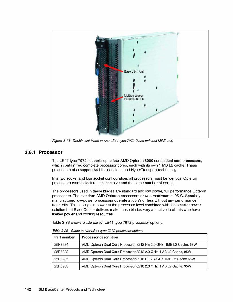
142 IBM BladeCenter Products and Technology
Figure 3-13 Double slot blade server LS41 type 7972 (base unit and MPE unit)
3.6.1 Processor
The LS41 type 7972 supports up to four AMD Opteron 8000 series dual-core processors, which contain two complete processor cores, each with its own 1 MB L2 cache. These processors also support 64-bit extensions and HyperTransport technology.
In a two socket and four socket configuration, all processors must be identical Opteron processors (same clock rate, cache size and the same number of cores).
The processors used in these blades are standard and low power, full performance Opteron processors. The standard AMD Opteron processors draw a maximum of 95 W. Specially manufactured low-power processors operate at 68 W or less without any performance trade-offs. This savings in power at the processor level combined with the smarter power solution that BladeCenter delivers make these blades very attractive to clients who have limited power and cooling resources.
Table 3-36 shows blade server LS41 type 7972 processor options.
Table 3-36 Blade server LS41 type 7972 processor options
Part number Processor description
25R8934 AMD Opteron Dual Core Processor 8212 HE 2.0 GHz, 1MB L2 Cache, 68W
25R8932 AMD Opteron Dual Core Processor 8212 2.0 GHz, 1MB L2 Cache, 95W
25R8935 AMD Opteron Dual Core Processor 8216 HE 2.4 GHz 1MB L2 Cache 68W
25R8933 AMD Opteron Dual Core Processor 8218 2.6 GHz, 1MB L2 Cache, 95W
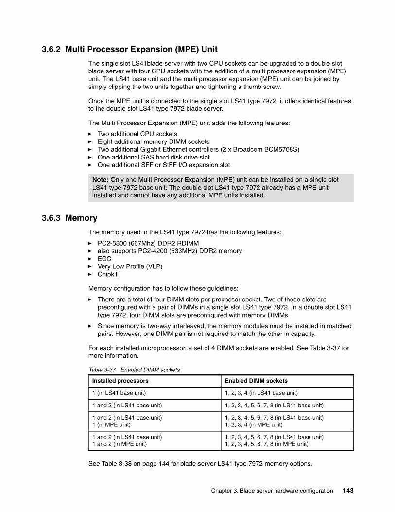
Chapter 3. Blade server hardware configuration 143
3.6.2 Multi Processor Expansion (MPE) Unit
The single slot LS41blade server with two CPU sockets can be upgraded to a double slot blade server with four CPU sockets with the addition of a multi processor expansion (MPE) unit. The LS41 base unit and the multi processor expansion (MPE) unit can be joined by simply clipping the two units together and tightening a thumb screw.
Once the MPE unit is connected to the single slot LS41 type 7972, it offers identical features to the double slot LS41 type 7972 blade server.
The Multi Processor Expansion (MPE) unit adds the following features:
� Two additional CPU sockets� Eight additional memory DIMM sockets� Two additional Gigabit Ethernet controllers (2 x Broadcom BCM5708S)� One additional SAS hard disk drive slot� One additional SFF or StFF I/O expansion slot
3.6.3 Memory
The memory used in the LS41 type 7972 has the following features:
� PC2-5300 (667Mhz) DDR2 RDIMM� also supports PC2-4200 (533MHz) DDR2 memory� ECC� Very Low Profile (VLP)� Chipkill
Memory configuration has to follow these guidelines:
� There are a total of four DIMM slots per processor socket. Two of these slots are preconfigured with a pair of DIMMs in a single slot LS41 type 7972. In a double slot LS41 type 7972, four DIMM slots are preconfigured with memory DIMMs.
� Since memory is two-way interleaved, the memory modules must be installed in matched pairs. However, one DIMM pair is not required to match the other in capacity.
For each installed microprocessor, a set of 4 DIMM sockets are enabled. See Table 3-37 for more information.
Table 3-37 Enabled DIMM sockets
See Table 3-38 on page 144 for blade server LS41 type 7972 memory options.
Note: Only one Multi Processor Expansion (MPE) unit can be installed on a single slot LS41 type 7972 base unit. The double slot LS41 type 7972 already has a MPE unit installed and cannot have any additional MPE units installed.
Installed processors Enabled DIMM sockets
1 (in LS41 base unit) 1, 2, 3, 4 (in LS41 base unit)
1 and 2 (in LS41 base unit) 1, 2, 3, 4, 5, 6, 7, 8 (in LS41 base unit)
1 and 2 (in LS41 base unit)1 (in MPE unit)
1, 2, 3, 4, 5, 6, 7, 8 (in LS41 base unit)1, 2, 3, 4 (in MPE unit)
1 and 2 (in LS41 base unit)1 and 2 (in MPE unit)
1, 2, 3, 4, 5, 6, 7, 8 (in LS41 base unit)1, 2, 3, 4, 5, 6, 7, 8 (in MPE unit)
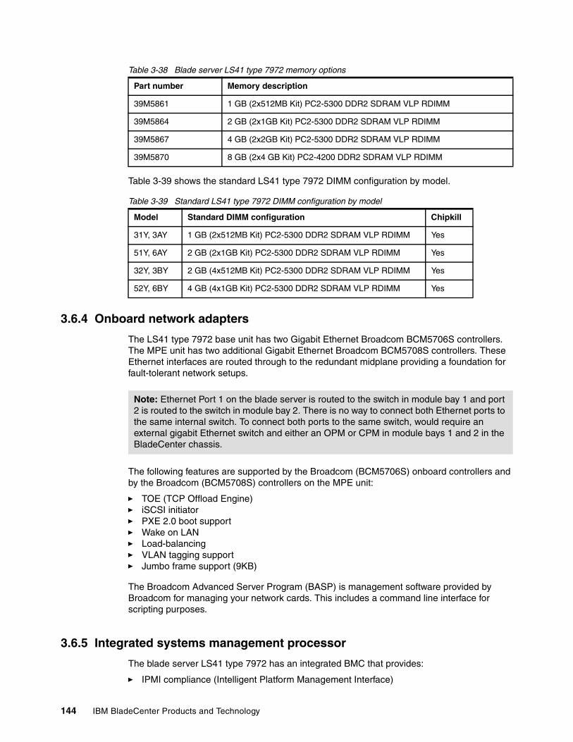
144 IBM BladeCenter Products and Technology
Table 3-38 Blade server LS41 type 7972 memory options
Table 3-39 shows the standard LS41 type 7972 DIMM configuration by model.
Table 3-39 Standard LS41 type 7972 DIMM configuration by model
3.6.4 Onboard network adapters
The LS41 type 7972 base unit has two Gigabit Ethernet Broadcom BCM5706S controllers. The MPE unit has two additional Gigabit Ethernet Broadcom BCM5708S controllers. These Ethernet interfaces are routed through to the redundant midplane providing a foundation for fault-tolerant network setups.
The following features are supported by the Broadcom (BCM5706S) onboard controllers and by the Broadcom (BCM5708S) controllers on the MPE unit:
� TOE (TCP Offload Engine)� iSCSI initiator� PXE 2.0 boot support� Wake on LAN � Load-balancing� VLAN tagging support� Jumbo frame support (9KB)
The Broadcom Advanced Server Program (BASP) is management software provided by Broadcom for managing your network cards. This includes a command line interface for scripting purposes.
3.6.5 Integrated systems management processor
The blade server LS41 type 7972 has an integrated BMC that provides:
� IPMI compliance (Intelligent Platform Management Interface)
Part number Memory description
39M5861 1 GB (2x512MB Kit) PC2-5300 DDR2 SDRAM VLP RDIMM
39M5864 2 GB (2x1GB Kit) PC2-5300 DDR2 SDRAM VLP RDIMM
39M5867 4 GB (2x2GB Kit) PC2-5300 DDR2 SDRAM VLP RDIMM
39M5870 8 GB (2x4 GB Kit) PC2-4200 DDR2 SDRAM VLP RDIMM
Model Standard DIMM configuration Chipkill
31Y, 3AY 1 GB (2x512MB Kit) PC2-5300 DDR2 SDRAM VLP RDIMM Yes
51Y, 6AY 2 GB (2x1GB Kit) PC2-5300 DDR2 SDRAM VLP RDIMM Yes
32Y, 3BY 2 GB (4x512MB Kit) PC2-5300 DDR2 SDRAM VLP RDIMM Yes
52Y, 6BY 4 GB (4x1GB Kit) PC2-5300 DDR2 SDRAM VLP RDIMM Yes
Note: Ethernet Port 1 on the blade server is routed to the switch in module bay 1 and port 2 is routed to the switch in module bay 2. There is no way to connect both Ethernet ports to the same internal switch. To connect both ports to the same switch, would require an external gigabit Ethernet switch and either an OPM or CPM in module bays 1 and 2 in the BladeCenter chassis.
Chapter 3. Blade server hardware configuration 145
� Serial over LAN (SOL) � Wake on LAN (WOL) � Power management functions� KVM and media tray ownership� Light path diagnostics support� Automatic BIOS recovery (ABR)� Automatic server restart (ASR)� Predictive failure analysis (PFA) on system components (CPUs, memory, and drives)� Inventory� Error logging� Environmental monitoring (voltages and temperature on the system board)
Note that you cannot access this onboard BMC externally through a dedicated port or daisy-chain it to other servers or blades. The BMC is forwarding information to the Management Module (MM) within the BladeCenter chassis. The MM is a single point of control for hardware management of all server and switch components contained within the chassis.
3.6.6 Local storage options
The single slot LS41 type 7972 blade server base unit features an onboard LSI Logic 53C1064 SAS controller with a SAS connector for one optional 2.5-inch Small Form Factor (SFF) SAS hard disk drive. The multi processor expansion (MPE) unit has a SAS connector for an additional 2.5-inch SFF SAS hard disk drive. Therefore in a double slot LS41 type 7972 blade server (LS41 base unit and MPE unit) it is possible to have two SAS hard disk drives in a RAID 0 or RAID 1 array.
Table 3-5 on page 114 shows the SFF HDD options for LS41 type 7972.
Table 3-40 Small form factor (SFF) hard disk drive options for LS41 type 7972
The hard disk drive is mounted onto the system board of the blade server and are inaccessible from the outside during operation.
BladeCenter Storage and I/O Expansion Unit (SIO)The LS41 type 7972 supports the attachment of one BladeCenter Storage and I/O expansion unit. For more information about the SIO, see 3.10, “BladeCenter Storage and I/O Expansion Unit” on page 156
3.6.7 I/O expansion options
The single slot LS41 type 7972 base unit has one onboard connector for various StFF or SFF I/O expansion options including network and storage adapters. This onboard connector is connected to module bays 3 and 4 at the rear of the BladeCenter chassis. The interface of the I/O expansion slot is a PCI-X 133 MHz bus.
Part number Description
26K5776 36.4 GB SAS HDD (2.5") SFF
26K5777 73 GB SAS HDD (2.5") SFF
Note: The LS41 type 7972 does not support the attachment of any of the previous BSE-I or BSE-II expansion units.
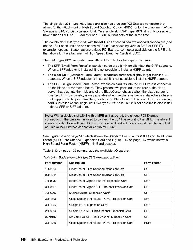
146 IBM BladeCenter Products and Technology
The single slot LS41 type 7972 base unit also has a unique PCI Express connector that allows for the attachment of High Speed Daughter Cards (HSDC) or for the attachment of the Storage and I/O (SIO) Expansion Unit. On a single slot LS41 type 7971, it is only possible to have either a StFF or SFF adapter or a HSDC but not both at the same time.
The double slot LS41 type 7972 with the MPE unit attached has two onboard connectors (one on the LS41 base unit and one on the MPE unit) for attaching various StFF or SFF I/O expansion options. It also has one unique PCI Express connector available on the MPE unit that allows for the attachment of High Speed Daughter Cards (HSDC).
The LS41 type 7972 supports three different form factors for expansion cards.
� The SFF (Small Form Factor) expansion cards are slightly smaller than the StFF adapters. When a SFF adapter is installed, it is not possible to install a HSFF adapter.
� The older StFF (Standard Form Factor) expansion cards are slightly larger than the SFF adapters. When a StFF adapter is installed, it is not possible to install a HSFF adapter.
� The HSFF (High Speed Form Factor) expansion card fits into the PCI Express connector on the blade server motherboard. They present two ports out of the rear of the blade server that plug into the midplane of the BladeCenter chassis when the blade server is inserted. This functionality is only available when the blade server is installed in a chassis that supports high speed switches, such as the BladeCenter H. When a HSFF expansion card is installed on the single slot LS41 type 7972 base unit, it is not possible to also install either a SFF or StFF adapter.
See Figure 3-14 on page 147 which shows the Standard Form Factor (StFF) and Small Form Factor (SFF) Fibre Channel Expansion Card and Figure 3-15 on page 147 which shows a High Speed Form Factor (HSFF) InfiniBand adapter.
Table 3-13 on page 122 summarizes the available I/O options.
Table 3-41 Blade server LS41 type 7972 expansion options
Note: With a double slot LS41 with a MPE unit attached, the unique PCI Express connector on the base unit is used to connect the LS41 base unit to the MPE. Therefore it is only possible to install one HSFF expansion card and in this instance it must be installed on unique PCI Express connector on the MPE unit.
Part number Description Form Factor
13N2203 BladeCenter Fibre Channel Expansion Card StFF
26K4841 BladeCenter Fibre Channel Expansion Card SFF
73P9030 BladeCenter Gigabit Ethernet Expansion Card StFF
39R8624 BladeCenter Gigabit SFF Ethernet Expansion Card SFF
73P6000 Myrinet Cluster Expansion Carda StFF
32R1896 Cisco Systems InfiniBand 1X HCA Expansion Card SFF
32R1923 QLogic iSCSI Expansion Card StFF
26R0890 QLogic 4 Gb SFF Fibre Channel Expansion Card SFF
39Y9186 Emulex 4 Gb SFF Fibre Channel Expansion Card SFF
32R1760 Cisco Systems InfiniBand 4X HCA Expansion Card HSFF
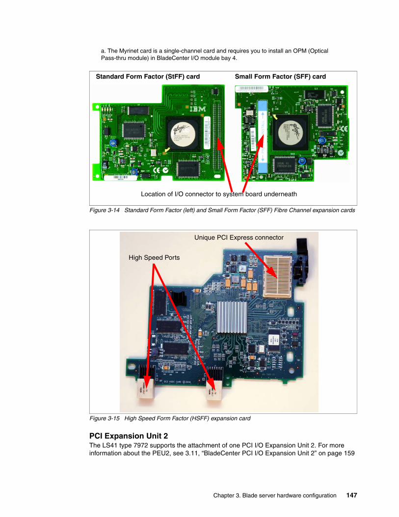
Chapter 3. Blade server hardware configuration 147
Figure 3-14 Standard Form Factor (left) and Small Form Factor (SFF) Fibre Channel expansion cards
Figure 3-15 High Speed Form Factor (HSFF) expansion card
PCI Expansion Unit 2The LS41 type 7972 supports the attachment of one PCI I/O Expansion Unit 2. For more information about the PEU2, see 3.11, “BladeCenter PCI I/O Expansion Unit 2” on page 159
a. The Myrinet card is a single-channel card and requires you to install an OPM (Optical Pass-thru module) in BladeCenter I/O module bay 4.
Location of I/O connector to system board underneath
Standard Form Factor (StFF) card Small Form Factor (SFF) card
Unique PCI Express connector
High Speed Ports
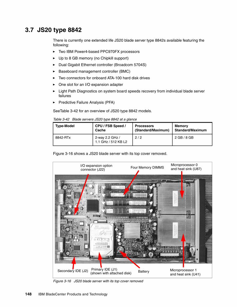
148 IBM BladeCenter Products and Technology
3.7 JS20 type 8842
There is currently one extended life JS20 blade server type 8842s available featuring the following:
� Two IBM Power4-based PPC970FX processors
� Up to 8 GB memory (no Chipkill support)
� Dual Gigabit Ethernet controller (Broadcom 5704S)
� Baseboard management controller (BMC)
� Two connectors for onboard ATA-100 hard disk drives
� One slot for an I/O expansion adapter
� Light Path Diagnostics on system board speeds recovery from individual blade server failures
� Predictive Failure Analysis (PFA)
SeeTable 3-42 for an overview of JS20 type 8842 models.
Table 3-42 Blade servers JS20 type 8842 at a glance
Figure 3-16 shows a JS20 blade server with its top cover removed.
Figure 3-16 JS20 blade server with its top cover removed
Type-Model CPU / FSB Speed / Cache
Processors (Standard/Maximum)
Memory Standard/Maximum
8842-RTx 2-way 2.2 GHz / 1.1 GHz / 512 KB L2
2 / 2 2 GB / 8 GB
I/O expansion optionconnector (J22)
Four Memory DIMMSMicroprocessor 0and heat sink (U87)
Microprocessor 1and heat sink (U41)
BatteryPrimary IDE (J1)(shown with attached disk)
Secondary IDE (J2)
Chapter 3. Blade server hardware configuration 149
3.7.1 Processor
The JS20 blade server comes standard with two processors. There are no processor upgrade options.
3.7.2 Memory
The memory subsystem is comprised of the memory controller and up to four DDR1 333 MHz (PC2700) ECC memory modules. The memory controller uses two-way interleaving to increase the available peak memory bandwidth to 5.3 GBps (333 MHz x 16 bytes).
The BladeCenter JS20 includes two 1 GB memory modules that provide a total memory capacity of 2 GB. These memory modules are installed in slots 3 and 4. The remaining memory module slots (1 and 2) are empty in the base BladeCenter JS20.
You can expand the available memory by installing optional memory modules. The available memory modules are listed in Table 3-43:
Table 3-43 JS20 memory module options
Since memory is two-way interleaved, you must install the memory modules in matched pairs. However, one DIMM pair is not required to match the other in capacity. See Table 3-44.
Table 3-44 JS20 Standard DIMM configuration
3.7.3 Onboard network adapters
The JS20 blade server type 8842 has a dual channel Gigabit Ethernet Broadcom BCM5704S. These two Ethernet interfaces are routed through to the redundant midplane providing a foundation for fault-tolerant network setups.
The Broadcom onboard adapter supports the following features:
� PXE boot support� Wake on LAN � Load-balancing� Fault-tolerance� VLAN support
The Broadcom Advanced Server Program (BASP) is management software Broadcom provides for managing your network cards. This software includes a command line interface for scripting purposes.
Part number Description
39M5839 1 GB (1 x 1GB DIMM) PC2700 ECC DDR RDIMM
39M5843 2 GB (1 x 2GB DIMM) PC2700 ECC DDR RDIMM
Model Standard DIMM configuration
RTx 2 x 1 GB PC2700 ECC DDR RDIMM
150 IBM BladeCenter Products and Technology
3.7.4 Integrated systems management processor
The JS20 blade server type 8842 has an integrated baseboard management controller (BMC) that provides:
� IPMI compliance (Intelligent Platform Management Interface)
� Serial over LAN (SOL)
� Wake on LAN (WOL)
� Power management functions
� KVM and media tray ownership
� Light path diagnostics support
� Automatic BIOS recovery (ABR)
� Automatic server restart (ASR)
� Predictive failure analysis (PFA) on system components (processor, memory, and hard disk drives)
� Inventory
� Error logging
� Environmental monitoring (voltages and temperature on the system board of the blade server)
The BMC is based on an Hitachi H8 chip that communicates with the Management Module in the BladeCenter Chassis via an internal RS-485 interface.
Note that this onboard BMC cannot be accessed externally through a dedicated port or be daisy-chained to other servers or blades. The BMC is forwarding information to the Management Module (MM) within the BladeCenter chassis. The MM is a single point of control for hardware management of all server and switch components contained within the chassis.
3.7.5 Local storage options
The JS20 blade server has an integrated ATA-100 controller with two channels and two independent connectors. The controller does not have RAID capability. The available hard disk drive options are summarized in Table 3-45.
Table 3-45 Hard disk drive options for the JS20 type 8842
Note: The onboard Broadcom controller only runs at the speed of 1 Gb/s. This is important in integration of the Optical or Copper Pass-thru Module since the speed cannot be reduced to 100 or 10 Mbps.
If you need to have network connections at 10 or 100 Mbps, you need to use additional external network switches. This cannot be achieved with any internal network switch option for the BladeCenter or BladeCenter T.
Part number Description Height
25R6904 BladeCenter 60 GB 5400 rpm ATA-100 HDD Slim
Chapter 3. Blade server hardware configuration 151
The JS20 blade server has an onboard PCI-X connector for various I/O expansion options including network and storage adapters. These adapters are connected to module bays 3 and 4 at the rear of the BladeCenter chassis. The interface of the I/O expansion slot is a PCI-X 133 MHz bus.
Table 3-46 summarizes the available options.
� An expansion I/O card requires appropriate I/O modules to be installed in the BladeCenter chassis.
� The Myrinet Cluster expansion card is a single channel card and requires an OPM I/O module to be installed in BladeCenter I/O module bay 4.
� One expansion card is allowed per blade server and installs over IDE HDD bay 2, preventing installation of a second IDE HDD.
Table 3-46 JS20 blade server I/O expansion options
3.8 JS21 type 8844
The BladeCenter JS21 server represents the newest offering in the BladeCenter family of high-density, high-performance PowerPC based servers, with multi-socket processors and high-speed memory options.
Key features of the JS21 include the following:
� Two 64-bit PowerPC 970MP processors
� Up to 16 GB ECC Chipkill DDR2 memory
� Dual Gigabit Ethernet controller (Broadcom 5780)
� One slot for an I/O expansion adapter
� Light Path Diagnostics on system board speeds recovery from individual blade server failures
Part number Description Form Factor
73P6000 Myricom Myrinet Expansion Card for BladeCentera
a. The Myrinet card is a single-channel card and requires you to install an OPM (Optical Pass-thru Module) in BladeCenter I/O module bay 4.
StFF
32R1923 Qlogic iSCSI Expansion Card for BladeCenter StFF
32R1896 Cisco Systems InfiniBand 1X HCA Expansion Card StFF
26R0884 QLogic 4 Gb Standard Fibre Channel Expansion Card StFF
Note: You can only use standard form factor expansion cards (StFF) in the JS20 blade server. When using a StFF expansion card, it will prevent you from installing a second hard disk drive onto the blade server system board.
You cannot use the newer small form factor expansion cards (SmFF) with the JS20 blade server.
Tip: Note that the JS20 blade server does not support the optional BladeCenter Storage Expansion Unit nor the PCI I/O Expansion Unit. The JS20 does not have the necessary interconnect.
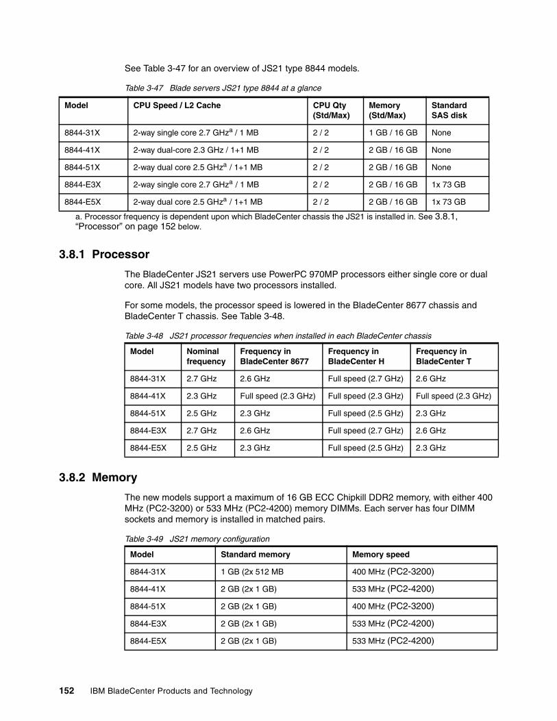
152 IBM BladeCenter Products and Technology
See Table 3-47 for an overview of JS21 type 8844 models.
Table 3-47 Blade servers JS21 type 8844 at a glance
3.8.1 Processor
The BladeCenter JS21 servers use PowerPC 970MP processors either single core or dual core. All JS21 models have two processors installed.
For some models, the processor speed is lowered in the BladeCenter 8677 chassis and BladeCenter T chassis. See Table 3-48.
Table 3-48 JS21 processor frequencies when installed in each BladeCenter chassis
3.8.2 Memory
The new models support a maximum of 16 GB ECC Chipkill DDR2 memory, with either 400 MHz (PC2-3200) or 533 MHz (PC2-4200) memory DIMMs. Each server has four DIMM sockets and memory is installed in matched pairs.
Table 3-49 JS21 memory configuration
Model CPU Speed / L2 Cache CPU Qty (Std/Max)
Memory (Std/Max)
Standard SAS disk
8844-31X 2-way single core 2.7 GHza / 1 MB 2 / 2 1 GB / 16 GB None
8844-41X 2-way dual-core 2.3 GHz / 1+1 MB 2 / 2 2 GB / 16 GB None
8844-51X 2-way dual core 2.5 GHza / 1+1 MB 2 / 2 2 GB / 16 GB None
8844-E3X 2-way single core 2.7 GHza / 1 MB 2 / 2 2 GB / 16 GB 1x 73 GB
8844-E5X 2-way dual core 2.5 GHza / 1+1 MB 2 / 2 2 GB / 16 GB 1x 73 GB
a. Processor frequency is dependent upon which BladeCenter chassis the JS21 is installed in. See 3.8.1, “Processor” on page 152 below.
Model Nominal frequency
Frequency in BladeCenter 8677
Frequency in BladeCenter H
Frequency in BladeCenter T
8844-31X 2.7 GHz 2.6 GHz Full speed (2.7 GHz) 2.6 GHz
8844-41X 2.3 GHz Full speed (2.3 GHz) Full speed (2.3 GHz) Full speed (2.3 GHz)
8844-51X 2.5 GHz 2.3 GHz Full speed (2.5 GHz) 2.3 GHz
8844-E3X 2.7 GHz 2.6 GHz Full speed (2.7 GHz) 2.6 GHz
8844-E5X 2.5 GHz 2.3 GHz Full speed (2.5 GHz) 2.3 GHz
Model Standard memory Memory speed
8844-31X 1 GB (2x 512 MB 400 MHz (PC2-3200)
8844-41X 2 GB (2x 1 GB) 533 MHz (PC2-4200)
8844-51X 2 GB (2x 1 GB) 400 MHz (PC2-3200)
8844-E3X 2 GB (2x 1 GB) 533 MHz (PC2-4200)
8844-E5X 2 GB (2x 1 GB) 533 MHz (PC2-4200)
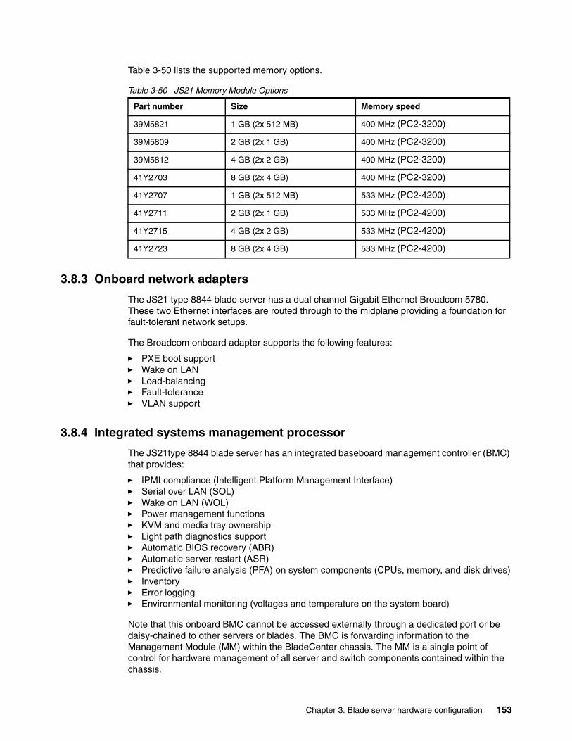
Chapter 3. Blade server hardware configuration 153
Table 3-50 lists the supported memory options.
Table 3-50 JS21 Memory Module Options
3.8.3 Onboard network adapters
The JS21 type 8844 blade server has a dual channel Gigabit Ethernet Broadcom 5780. These two Ethernet interfaces are routed through to the midplane providing a foundation for fault-tolerant network setups.
The Broadcom onboard adapter supports the following features:
� PXE boot support� Wake on LAN � Load-balancing� Fault-tolerance� VLAN support
3.8.4 Integrated systems management processor
The JS21type 8844 blade server has an integrated baseboard management controller (BMC) that provides:
� IPMI compliance (Intelligent Platform Management Interface)� Serial over LAN (SOL) � Wake on LAN (WOL) � Power management functions� KVM and media tray ownership� Light path diagnostics support� Automatic BIOS recovery (ABR)� Automatic server restart (ASR)� Predictive failure analysis (PFA) on system components (CPUs, memory, and disk drives)� Inventory� Error logging� Environmental monitoring (voltages and temperature on the system board)
Note that this onboard BMC cannot be accessed externally through a dedicated port or be daisy-chained to other servers or blades. The BMC is forwarding information to the Management Module (MM) within the BladeCenter chassis. The MM is a single point of control for hardware management of all server and switch components contained within the chassis.
Part number Size Memory speed
39M5821 1 GB (2x 512 MB) 400 MHz (PC2-3200)
39M5809 2 GB (2x 1 GB) 400 MHz (PC2-3200)
39M5812 4 GB (2x 2 GB) 400 MHz (PC2-3200)
41Y2703 8 GB (2x 4 GB) 400 MHz (PC2-3200)
41Y2707 1 GB (2x 512 MB) 533 MHz (PC2-4200)
41Y2711 2 GB (2x 1 GB) 533 MHz (PC2-4200)
41Y2715 4 GB (2x 2 GB) 533 MHz (PC2-4200)
41Y2723 8 GB (2x 4 GB) 533 MHz (PC2-4200)
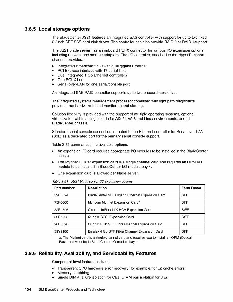
154 IBM BladeCenter Products and Technology
3.8.5 Local storage options
The BladeCenter JS21 features an integrated SAS controller with support for up to two fixed 2.5inch SFF SAS hard disk drives. The controller can also provide RAID 0 or RAID 1support.
The JS21 blade server has an onboard PCI-X connector for various I/O expansion options including network and storage adapters. The I/O controller, attached to the HyperTransport channel, provides:
� Integrated Broadcom 5780 with dual gigabit Ethernet� PCI Express interface with 17 serial links� Dual integrated 1 Gb Ethernet controllers� One PCI-X bus� Serial-over-LAN for one serial/console port
An integrated SAS RAID controller supports up to two onboard hard drives.
The integrated systems management processor combined with light path diagnostics provides true hardware-based monitoring and alerting.
Solution flexibility is provided with the support of multiple operating systems, optional virtualization within a single blade for AIX 5L V5.3 and Linux environments, and all BladeCenter chassis.
Standard serial console connection is routed to the Ethernet controller for Serial-over-LAN (SoL) as a dedicated port for the primary serial console support.
Table 3-51 summarizes the available options.
� An expansion I/O card requires appropriate I/O modules to be installed in the BladeCenter chassis.
� The Myrinet Cluster expansion card is a single channel card and requires an OPM I/O module to be installed in BladeCenter I/O module bay 4.
� One expansion card is allowed per blade server.
Table 3-51 JS21 blade server I/O expansion options
3.8.6 Reliability, Availability, and Serviceability Features
Component-level features include:
� Transparent CPU hardware error recovery (for example, for L2 cache errors)� Memory scrubbing� Single DIMM failure isolation for CEs; DIMM pair isolation for UEs
Part number Description Form Factor
39R8624 BladeCenter SFF Gigabit Ethernet Expansion Card SFF
73P6000 Myricom Myrinet Expansion Carda
a. The Myrinet card is a single-channel card and requires you to install an OPM (Optical Pass-thru Module) in BladeCenter I/O module bay 4.
SFF
32R1896 Cisco InfiniBand 1X HCA Expansion Card StFF
32R1923 QLogic iSCSI Expansion Card StFF
26R0890 QLogic 4 Gb SFF Fibre Channel Expansion Card SFF
39Y9186 Emulex 4 Gb SFF Fibre Channel Expansion Card SFF
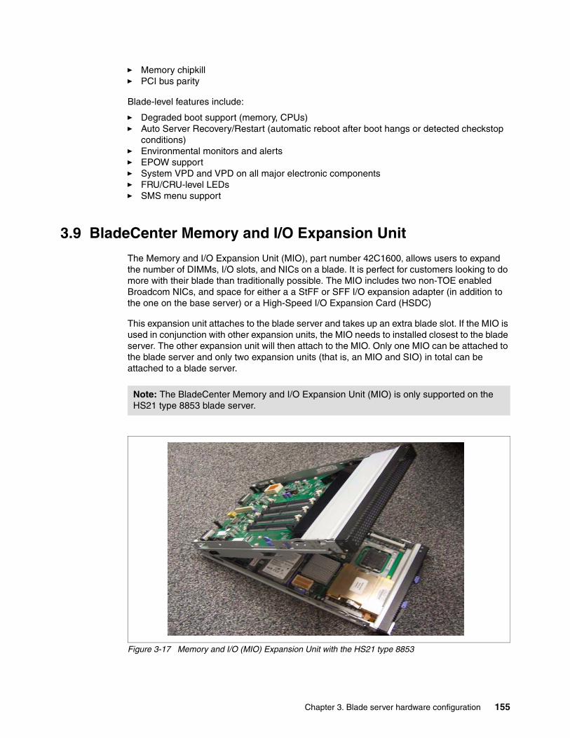
Chapter 3. Blade server hardware configuration 155
� Memory chipkill� PCI bus parity
Blade-level features include:
� Degraded boot support (memory, CPUs)� Auto Server Recovery/Restart (automatic reboot after boot hangs or detected checkstop
conditions)� Environmental monitors and alerts� EPOW support� System VPD and VPD on all major electronic components� FRU/CRU-level LEDs� SMS menu support
3.9 BladeCenter Memory and I/O Expansion Unit
The Memory and I/O Expansion Unit (MIO), part number 42C1600, allows users to expand the number of DIMMs, I/O slots, and NICs on a blade. It is perfect for customers looking to do more with their blade than traditionally possible. The MIO includes two non-TOE enabled Broadcom NICs, and space for either a a StFF or SFF I/O expansion adapter (in addition to the one on the base server) or a High-Speed I/O Expansion Card (HSDC)
This expansion unit attaches to the blade server and takes up an extra blade slot. If the MIO is used in conjunction with other expansion units, the MIO needs to installed closest to the blade server. The other expansion unit will then attach to the MIO. Only one MIO can be attached to the blade server and only two expansion units (that is, an MIO and SIO) in total can be attached to a blade server.
Figure 3-17 Memory and I/O (MIO) Expansion Unit with the HS21 type 8853
Note: The BladeCenter Memory and I/O Expansion Unit (MIO) is only supported on the HS21 type 8853 blade server.
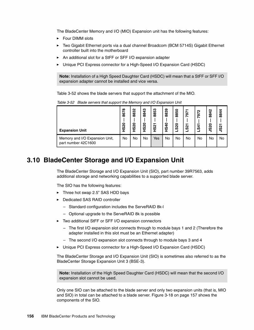
156 IBM BladeCenter Products and Technology
The BladeCenter Memory and I/O (MIO) Expansion unit has the following features:
� Four DIMM slots
� Two Gigabit Ethernet ports via a dual channel Broadcom (BCM 5714S) Gigabit Ethernet controller built into the motherboard
� An additional slot for a StFF or SFF I/O expansion adapter
� Unique PCI Express connector for a High-Speed I/O Expansion Card (HSDC)
Table 3-52 shows the blade servers that support the attachment of the MIO.
Table 3-52 Blade servers that support the Memory and I/O Expansion Unit
3.10 BladeCenter Storage and I/O Expansion Unit
The BladeCenter Storage and I/O Expansion Unit (SIO), part number 39R7563, adds additional storage and networking capabilities to a supported blade server.
The SIO has the following features:
� Three hot swap 2.5” SAS HDD bays
� Dedicated SAS RAID controller
– Standard configuration includes the ServeRAID 8k-l
– Optional upgrade to the ServeRAID 8k is possible
� Two additional StFF or SFF I/O expansion connectors
– The first I/O expansion slot connects through to module bays 1 and 2 (Therefore the adapter installed in this slot must be an Ethernet adapter)
– The second I/O expansion slot connects through to module bays 3 and 4
� Unique PCI Express connector for a High-Speed I/O Expansion Card (HSDC)
The BladeCenter Storage and I/O Expansion Unit (SIO) is sometimes also referred to as the BladeCenter Storage Expansion Unit 3 (BSE-3).
Only one SIO can be attached to the blade server and only two expansion units (that is, MIO and SIO) in total can be attached to a blade server. Figure 3-18 on page 157 shows the components of the SIO.
Note: Installation of a High Speed Daughter Card (HSDC) will mean that a StFF or SFF I/O expansion adapter cannot be installed and vice versa.
Expansion Unit HS
20 —
867
8
HS
20 —
883
2
HS
20 —
884
3
HS
21 —
885
3
HS
40 —
883
9
LS
20 —
885
0
LS
21 —
797
1
LS
41—
797
2
JS20
— 8
842
JS21
— 8
844
Memory and I/O Expansion Unit, part number 42C1600
No No No Yes No No No No No No
Note: Installation of the High Speed Daughter Card (HSDC) will mean that the second I/O expansion slot cannot be used.
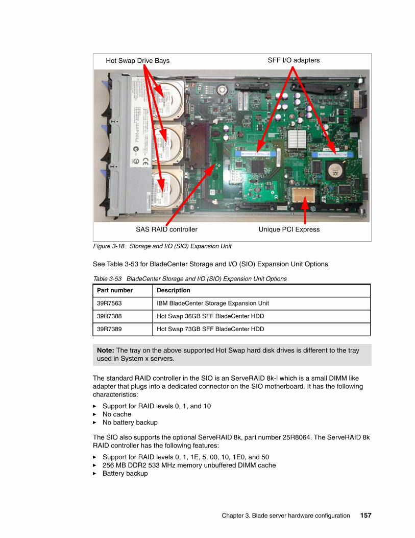
Chapter 3. Blade server hardware configuration 157
Figure 3-18 Storage and I/O (SIO) Expansion Unit
See Table 3-53 for BladeCenter Storage and I/O (SIO) Expansion Unit Options.
Table 3-53 BladeCenter Storage and I/O (SIO) Expansion Unit Options
The standard RAID controller in the SIO is an ServeRAID 8k-l which is a small DIMM like adapter that plugs into a dedicated connector on the SIO motherboard. It has the following characteristics:
� Support for RAID levels 0, 1, and 10� No cache� No battery backup
The SIO also supports the optional ServeRAID 8k, part number 25R8064. The ServeRAID 8k RAID controller has the following features:
� Support for RAID levels 0, 1, 1E, 5, 00, 10, 1E0, and 50� 256 MB DDR2 533 MHz memory unbuffered DIMM cache� Battery backup
Part number Description
39R7563 IBM BladeCenter Storage Expansion Unit
39R7388 Hot Swap 36GB SFF BladeCenter HDD
39R7389 Hot Swap 73GB SFF BladeCenter HDD
Note: The tray on the above supported Hot Swap hard disk drives is different to the tray used in System x servers.
Hot Swap Drive Bays SFF I/O adapters
SAS RAID controller Unique PCI Express
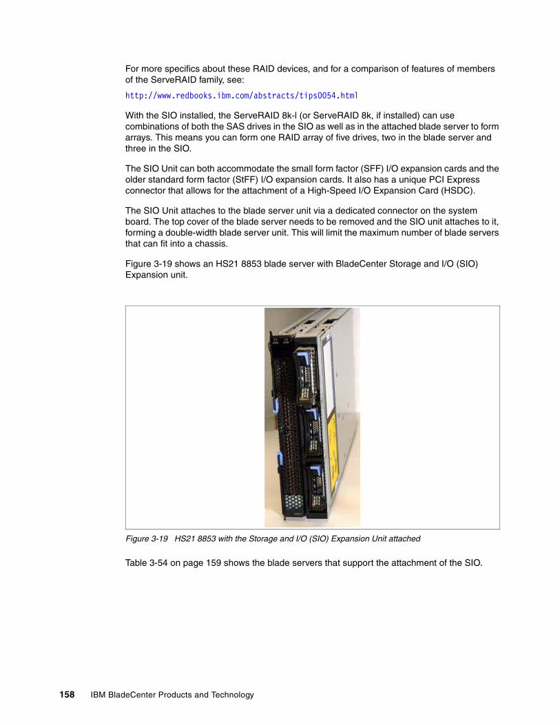
158 IBM BladeCenter Products and Technology
For more specifics about these RAID devices, and for a comparison of features of members of the ServeRAID family, see:
http://www.redbooks.ibm.com/abstracts/tips0054.html
With the SIO installed, the ServeRAID 8k-l (or ServeRAID 8k, if installed) can use combinations of both the SAS drives in the SIO as well as in the attached blade server to form arrays. This means you can form one RAID array of five drives, two in the blade server and three in the SIO.
The SIO Unit can both accommodate the small form factor (SFF) I/O expansion cards and the older standard form factor (StFF) I/O expansion cards. It also has a unique PCI Express connector that allows for the attachment of a High-Speed I/O Expansion Card (HSDC).
The SIO Unit attaches to the blade server unit via a dedicated connector on the system board. The top cover of the blade server needs to be removed and the SIO unit attaches to it, forming a double-width blade server unit. This will limit the maximum number of blade servers that can fit into a chassis.
Figure 3-19 shows an HS21 8853 blade server with BladeCenter Storage and I/O (SIO) Expansion unit.
Figure 3-19 HS21 8853 with the Storage and I/O (SIO) Expansion Unit attached
Table 3-54 on page 159 shows the blade servers that support the attachment of the SIO.
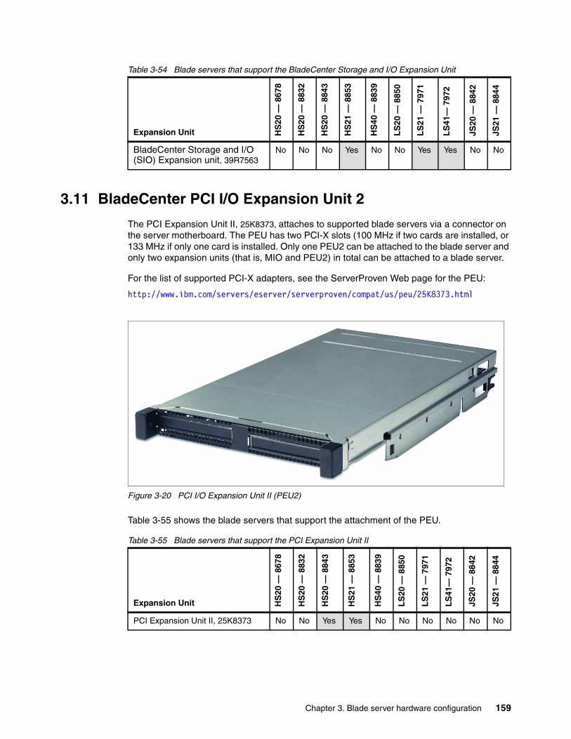
Chapter 3. Blade server hardware configuration 159
Table 3-54 Blade servers that support the BladeCenter Storage and I/O Expansion Unit
3.11 BladeCenter PCI I/O Expansion Unit 2
The PCI Expansion Unit II, 25K8373, attaches to supported blade servers via a connector on the server motherboard. The PEU has two PCI-X slots (100 MHz if two cards are installed, or 133 MHz if only one card is installed. Only one PEU2 can be attached to the blade server and only two expansion units (that is, MIO and PEU2) in total can be attached to a blade server.
For the list of supported PCI-X adapters, see the ServerProven Web page for the PEU:
http://www.ibm.com/servers/eserver/serverproven/compat/us/peu/25K8373.html
Figure 3-20 PCI I/O Expansion Unit II (PEU2)
Table 3-55 shows the blade servers that support the attachment of the PEU.
Table 3-55 Blade servers that support the PCI Expansion Unit II
Expansion Unit HS
20 —
867
8
HS
20 —
883
2
HS
20 —
884
3
HS
21 —
885
3
HS
40 —
883
9
LS
20 —
885
0
LS
21 —
797
1
LS
41—
797
2
JS20
— 8
842
JS21
— 8
844
BladeCenter Storage and I/O (SIO) Expansion unit, 39R7563
No No No Yes No No Yes Yes No No
Expansion Unit HS
20 —
867
8
HS
20 —
883
2
HS
20 —
884
3
HS
21 —
885
3
HS
40 —
883
9
LS
20 —
885
0
LS
21 —
797
1
LS
41—
797
2
JS20
— 8
842
JS21
— 8
844
PCI Expansion Unit II, 25K8373 No No Yes Yes No No No No No No
160 IBM BladeCenter Products and Technology
3.12 BladeCenter Expansion Cards
This section lists the currently available expansion cards that are installed in the blade servers for connectivity to I/O modules in the BladeCenter chassis.
See Table 1-3 on page 3 for a matrix showing which expansion cards are supported in each blade server.
3.12.1 BladeCenter Fibre Channel Expansion Card
The BladeCenter Fibre Channel Expansion Card, part number 13N2203, is a Fibre Channel Host Bus adapter that contains a single FC controller supporting two independent ports, each capable of up to 2 Gbps transmissions. This option replaces the Fibre Channel Expansion Card option, part number 48P7061.
3.12.2 BladeCenter 2 Gb Fibre Channel Expansion Card
The IBM BladeCenter SFF Fibre Channel Expansion Card, part number 26K4841, contains two Fibre Channel controllers supporting up to 2 Gbps transmissions. It provides functions equivalent to the IBM TotalStorage® FC2-133 Host Bus Adapter.
3.12.3 BladeCenter Gigabit Ethernet Expansion Card
The Gigabit Ethernet StFF expansion card, part number 73P9030, provides the blade server with two additional Gigabit ports. Increases capacity and allows for expansion of the Ethernet I/O subsystem, enables additional bandwidth and allows for connection to multiple LAN segments.
3.12.4 BladeCenter Gigabit SFF Ethernet Expansion Card
The BladeCenter SFF Gigabit Ethernet Expansion Card, part number 39R8624, provides each blade server with two additional Gigabit ports. This option increases capacity, allows for expansion of the Ethernet I/O subsystem, enables additional bandwidth and allows for connection to multiple LAN segments. It works in conjunction with all BladeCenter Fibre Channel switch options.
3.12.5 Cisco Systems InfiniBand 1X Host Channel Adapter Expansion Card
Cisco Systems InfiniBand 1X HCA Expansion Card, part number 32R1896. This is a standard form factor (StFF) expansion card.
3.12.6 QLogic iSCSI Expansion Card
The iSCSI Expansion Card, part number 26K6487, is a hardware initiator that provides iSCSI communication from the blade server to an iSCSI storage device (target).
With the iSCSI Expansion Card, you gain:
� Full hardware-based iSCSI initiator and TOE for storage traffic only (TCP/IP offload engine) function
� Blades enabled to run diskless in a non-Fibre Channel SAN environment
Chapter 3. Blade server hardware configuration 161
� Dual port card utilizing QLogic QMC4052 enabling iSCSI connectivity through switch module bays 3 and 4
� Standard BladeCenter expansion card form factor (full-sized expansion card)
� NEBS-compliant for use in NGN/Telco environments
3.12.7 QLogic 4 Gb Fibre Channel Expansion Cards
The QLogic 4 Gb Fibre Channel standard form factor (StFF) expansion card is available in either small form factor (SFF), part number 26R0890, or standard form factor (StFF), part number 26R0884. It provides a higher bandwidth connection between BladeCenter server blades and SAN switches. These 4 Gb expansion cards allow for a complete end-to-end 4 Gbps FC blade server to SAN solution.
Using the QLogic FC Expansion Card (HBA), and either a QLogic 4 Gb switch or a McDATA 4 Gb switch, and the IBM TotalStorage DS4800, IBM delivers an end-to-end 4 Gb SAN solution for blade servers. QLogic expansion cards feature dual port 1/2/4 Gb FC host bus adapter (HBA).
3.12.8 Emulex 4 GB SFF Fibre Channel Expansion Card
The Emulex 4 Gb Small-Form Factor (SFF) Fibre Channel expansion card, part number 39Y9186, is an addition to the family of IBM BladeCenter expansion cards, which delivers a higher bandwidth connection between BladeCenter server blades and SAN switches, and allows for a true end-to-end 4 Gb Fibre Channel blade server to a storage area network (SAN) solution. It is built based on the Emulex Helios Fibre Channel controller.
3.12.9 Cisco Systems InfiniBand 4X HCA Expansion Card
The Cisco Systems 4X InfiniBand HCA Expansion Card, part number 32R1760, provides connectivity to the Cisco Systems 4X InfiniBand Switch Module (see 2.10.1, “Cisco Systems 4X IB Switch Module for IBM BladeCenter” on page 92). Together they provide low-latency, high-bandwidth connectivity (up to 240 Gbps full duplex) to other BladeCenter chassis, stand-alone servers and external gateways.
Note: This card was previously named the Topspin InfiniBand 4X HCA Expansion Card.
Features:
� Dual 10 Gbps ports
� Server blade connection to one or two installed InfiniBand Switch Modules
� Ethernet and Fibre Channel connectivity for each InfiniBand connected server blade, through external gateways
The Cisco Systems 4X InfiniBand HCA Expansion Card is a High Speed Form Factor (HSFF) card.
3.12.10 Topspin InfiniBand Host Channel Adapter Expansion Card
The Topspin InfiniBand Host Channel Adapter (HCA) Expansion Card, part number 26K6457 has the following features:
� Dual 2.5 Gbps ports
� Server blade connection to one or two installed InfiniBand Switch Modules
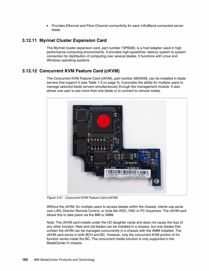
162 IBM BladeCenter Products and Technology
� Provides Ethernet and Fibre Channel connectivity for each InfiniBand connected server blade
3.12.11 Myrinet Cluster Expansion Card
The Myrinet cluster expansion card, part number 73P6000, is a host adapter used in high performance computing environments. It provides high-speed/low- latency system to system connection for distribution of computing over several blades. It functions with Linux and Windows operating systems.
3.12.12 Concurrent KVM Feature Card (cKVM)
The Concurrent KVM Feature Card (cKVM), part number 26K5939, can be installed in blade servers that support it (see Table 1-3 on page 3). It provides the ability for multiple users to manage selected blade servers simultaneously through the management module. It also allows one user to see more than one blade or to connect to remove media.
Figure 3-21 Concurrent KVM Feature Card (cKVM)
Without the cKVM, for multiple users to access blades within the chassis, clients use serial over LAN, Director Remote Control, or tools like RDC, VNC or PC Anywhere. The cKVM card allows this to take place via the MM or AMM.
Note: The cKVM card installs under the I/O daughter cards and does not cause the loss of any other function. New and old blades can be installed in a chassis, but only blades that contain the cKVM can be managed concurrently in a chassis with the AMM installed. The cKVM card works in both BCH and BC. However, only the concurrent KVM portion of it’s function works inside the BC. The concurrent media function is only supported in the BladeCenter H chassis.
© Copyright IBM Corp. 2007. All rights reserved. 163
Chapter 4. Network integration
This chapter describes different aspects of planning and implementing IBM BladeCenter-based network infrastructure. Several considerations have to be taken into account for successful implementation. They include systems management, performance, high availability and redundancy features, VLAN implementation, interoperability, and others.
This chapter covers the following topics:
� 4.1, “Switch module selection” on page 164
� 4.2, “VLAN” on page 164
� 4.3, “High availability and redundancy” on page 165
� 4.4, “Performance” on page 168
� 4.5, “Systems management” on page 170
4
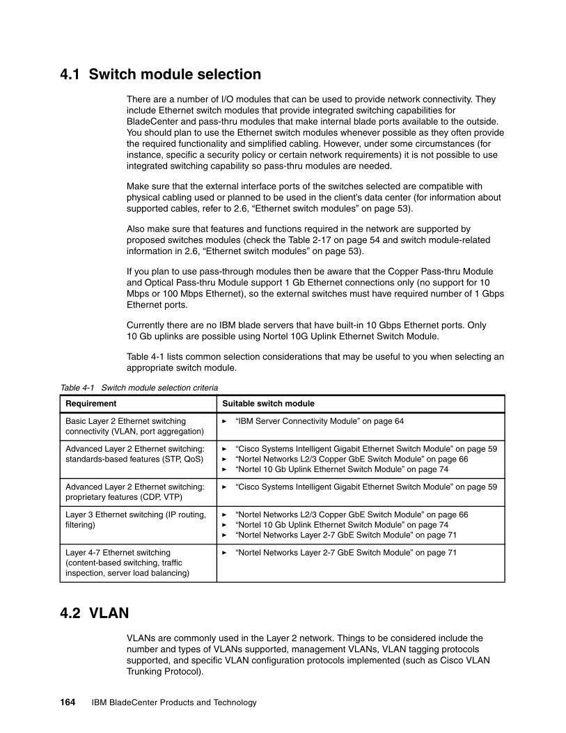
164 IBM BladeCenter Products and Technology
4.1 Switch module selection
There are a number of I/O modules that can be used to provide network connectivity. They include Ethernet switch modules that provide integrated switching capabilities for BladeCenter and pass-thru modules that make internal blade ports available to the outside. You should plan to use the Ethernet switch modules whenever possible as they often provide the required functionality and simplified cabling. However, under some circumstances (for instance, specific a security policy or certain network requirements) it is not possible to use integrated switching capability so pass-thru modules are needed.
Make sure that the external interface ports of the switches selected are compatible with physical cabling used or planned to be used in the client’s data center (for information about supported cables, refer to 2.6, “Ethernet switch modules” on page 53).
Also make sure that features and functions required in the network are supported by proposed switches modules (check the Table 2-17 on page 54 and switch module-related information in 2.6, “Ethernet switch modules” on page 53).
If you plan to use pass-through modules then be aware that the Copper Pass-thru Module and Optical Pass-thru Module support 1 Gb Ethernet connections only (no support for 10 Mbps or 100 Mbps Ethernet), so the external switches must have required number of 1 Gbps Ethernet ports.
Currently there are no IBM blade servers that have built-in 10 Gbps Ethernet ports. Only 10 Gb uplinks are possible using Nortel 10G Uplink Ethernet Switch Module.
Table 4-1 lists common selection considerations that may be useful to you when selecting an appropriate switch module.
Table 4-1 Switch module selection criteria
4.2 VLAN
VLANs are commonly used in the Layer 2 network. Things to be considered include the number and types of VLANs supported, management VLANs, VLAN tagging protocols supported, and specific VLAN configuration protocols implemented (such as Cisco VLAN Trunking Protocol).
Requirement Suitable switch module
Basic Layer 2 Ethernet switching connectivity (VLAN, port aggregation)
� “IBM Server Connectivity Module” on page 64
Advanced Layer 2 Ethernet switching: standards-based features (STP, QoS)
� “Cisco Systems Intelligent Gigabit Ethernet Switch Module” on page 59� “Nortel Networks L2/3 Copper GbE Switch Module” on page 66� “Nortel 10 Gb Uplink Ethernet Switch Module” on page 74
Advanced Layer 2 Ethernet switching: proprietary features (CDP, VTP)
� “Cisco Systems Intelligent Gigabit Ethernet Switch Module” on page 59
Layer 3 Ethernet switching (IP routing, filtering)
� “Nortel Networks L2/3 Copper GbE Switch Module” on page 66� “Nortel 10 Gb Uplink Ethernet Switch Module” on page 74� “Nortel Networks Layer 2-7 GbE Switch Module” on page 71
Layer 4-7 Ethernet switching (content-based switching, traffic inspection, server load balancing)
� “Nortel Networks Layer 2-7 GbE Switch Module” on page 71
Chapter 4. Network integration 165
All switch modules for IBM BladeCenter (including Cisco) support 802.1Q protocol for VLAN tagging. ISL protocol, which is Cisco proprietary protocol for VLAN tagging, is not supported (even on Cisco IGESMs).
Management VLANs are discussed in 4.5, “Systems management” on page 170.
Refer to the Table 2-17 on page 54 and switch module-related information in 2.6, “Ethernet switch modules” on page 53 for the switch module’s supported features and protocols.
4.3 High availability and redundancy
The clients may have requirements for continuous access to their network services and applications. Providing high availability for client network resources is a complex task which involves a lot of pieces needing to be put together both on a hardware and a software level. One of them is to provide network infrastructure availability.
Network infrastructure availability can be done by implementing certain techniques and technologies. Most of them are widely used standards, but some of them are specific to BladeCenter. We will discuss the most common technologies that can be implemented in a BladeCenter environment to provide high availability for network infrastructure.
In general, typical LAN infrastructure consists of server NICs, client NICs, network devices such as Ethernet switches and cables connecting all that things. The potential failures in a network include port failures (both on switches and servers), cable failures, and network device failures.
The first important thing is to avoid or minimize single points of failure, that is, to provide redundancy for network equipment and communication links. The BladeCenter chassis has built-in redundancy:
� Two Ethernet ports on each blade server� Two ports on I/O expansion cards on each blade server� Two separate communication paths to I/O modules through dual midplane connections� Two I/O bays per dual port for device redundancy
See Figure 2-14 on page 49, Figure 2-15 on page 51, and Figure 2-16 on page 52.
The second important thing is to implement technologies that will provide automatic failover in case of any failure. This can be done by using certain features protocols which are supported by network equipment, together with server-side software.
Consider the implementation of following technologies that could help to achieve higher level of availability in an IBM BladeCenter network solution (depends on your network architecture):
� Spanning Tree Protocol� Trunk Failover with NIC Teaming� Virtual Router Redundancy Protocol� Routing Protocol (such as RIP or OSPF)
4.3.1 Redundant network topologies
IBM BladeCenter can be connected to the enterprise network in several ways (see Figure 4-1).
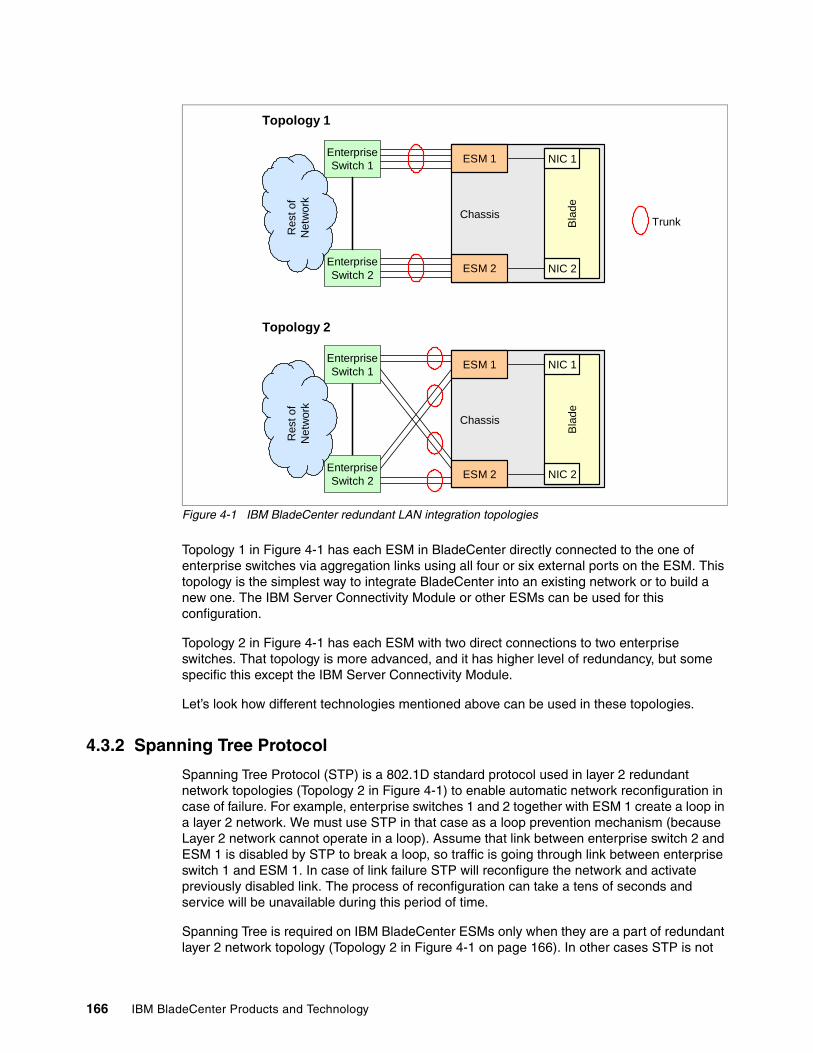
166 IBM BladeCenter Products and Technology
Figure 4-1 IBM BladeCenter redundant LAN integration topologies
Topology 1 in Figure 4-1 has each ESM in BladeCenter directly connected to the one of enterprise switches via aggregation links using all four or six external ports on the ESM. This topology is the simplest way to integrate BladeCenter into an existing network or to build a new one. The IBM Server Connectivity Module or other ESMs can be used for this configuration.
Topology 2 in Figure 4-1 has each ESM with two direct connections to two enterprise switches. That topology is more advanced, and it has higher level of redundancy, but some specific this except the IBM Server Connectivity Module.
Let’s look how different technologies mentioned above can be used in these topologies.
4.3.2 Spanning Tree Protocol
Spanning Tree Protocol (STP) is a 802.1D standard protocol used in layer 2 redundant network topologies (Topology 2 in Figure 4-1) to enable automatic network reconfiguration in case of failure. For example, enterprise switches 1 and 2 together with ESM 1 create a loop in a layer 2 network. We must use STP in that case as a loop prevention mechanism (because Layer 2 network cannot operate in a loop). Assume that link between enterprise switch 2 and ESM 1 is disabled by STP to break a loop, so traffic is going through link between enterprise switch 1 and ESM 1. In case of link failure STP will reconfigure the network and activate previously disabled link. The process of reconfiguration can take a tens of seconds and service will be unavailable during this period of time.
Spanning Tree is required on IBM BladeCenter ESMs only when they are a part of redundant layer 2 network topology (Topology 2 in Figure 4-1 on page 166). In other cases STP is not
Bla
deChassis
NIC 2
NIC 1ESM 1EnterpriseSwitch 1
EnterpriseSwitch 2 ESM 2
Res
t of
Net
wor
k
Bla
deChassis
NIC 2
NIC 1ESM 1EnterpriseSwitch 1
EnterpriseSwitch 2 ESM 2
Res
t of
Net
wor
k
Trunk
Topology 1
Topology 2
Chapter 4. Network integration 167
required. Whenever possible plan to use trunks (aggregated links) with VLAN tagging for interswitch connections.
Refer to Table 2-17 on page 54 for a list of switches supporting STP and refer to 2.6, “Ethernet switch modules” on page 53 for additional information.
4.3.3 Trunk Failover with NIC Teaming
Depending on the configuration, each blade can have one IP address per each Ethernet port, or it can have one virtual NIC consisting of two or more physical interfaces with one IP address. This is known as a NIC teaming technology. From BladeCenter point of view, NIC Teaming is useful when you plan to implement high availability configurations with automatic failover in case of internal or upstream link failures.
We can use only two ports on blades per virtual NIC for high availability configurations — one port is active (transferring data), and another is standby (waiting for failure of the active port). One (for instance, the active port) port should be connected to ESM in I/O bay 1, and another (for instance, the standby port) port should be connected to ESM in I/O bay 2. If you plan to use Ethernet expansion card for high availability configurations then the same rules apply. Active and standby ports should be connected to ESMs on different midplanes (that is, active ports to bay 1 or 3, and standby ports to bay 2 or 4).
In the case of internal port or link failure of the active NIC, the teaming driver switches the port roles; that is the standby port becomes active and the active port becomes standby. This is done very quickly, within a few seconds, and after restoration of the failed link, the teaming driver can perform a failback or can simply do nothing, depending on configuration.
Let’s look at the Topology 1 on Figure 4-1 on page 166. Assume that NIC Teaming is on and blade NIC port connected to ESM 1 is active and other is standby. If something goes wrong with internal link to ESM 1 then teaming driver will do a failover. But what will happen if external connections will be lost (connection from ESM 1 to Enterprise Switch 1)? The answer is that nothing happens because internal link is still on and teaming driver does not do a failover. So network service becomes unavailable.
To address this issue, the Trunk Failover technique is used. Trunk Failover can disable all internal ports on ESM in the case of an upstream links failure. Disabled port means no link so NIC teaming driver performs a failover. This is a special feature supported only on IBM BladeCenter ESMs. Thus if Trunk Failover is enabled and we lose connectivity with enterprise switch 1 then NIC teaming driver will perform a failover and service will be available through enterprise switch 2 and ESM 2.
Trunk Failover should be used with NIC active/standby teaming. Before planning to use NIC teaming check if it is supported by the operating system and applications deployed.
All current blade servers use integrated Broadcom Gigabit Ethernet controllers. NIC Teaming can be implemented by using certain software drivers from Broadcom (for instance, the Broadcom Advanced Server Program (BASP) is used with IBM blade servers and Windows and Novell operating systems) or by using specific drivers in the operating system (such as bonding in Linux). So, if BASP or bonding is used for NIC teaming and you’re implementing Trunk Failover, then only two NICs (one active, one standby) can be grouped into one logical interface (BASP supports only one standby NIC per virtual NIC, bonding mode 1 used for active/backup supports only two interfaces). Please consult corresponding documentation for additional information.
Refer to Table 2-17 on page 54 for a list of switches supporting Trunk Failover.
168 IBM BladeCenter Products and Technology
Refer to 2.6, “Ethernet switch modules” on page 53 for additional information.
4.3.4 Virtual Router Redundancy Protocol
If you’re integrating IBM BladeCenter into a Layer 3 network with different subnets, routing and routing protocols, some Layer 3 techniques can be used to provide service availability to clients. Traditionally, in multi-subnet IP networks, client workstations and servers use IP default gateways to be able to communicate with each other. In a redundant network in case of router failure (which is a default gateway), certain protocols should be used to preserve network connectivity between servers and clients. One of them is Virtual Router Redundancy Protocol (VRRP).
VRRP uses the virtual router concept, that is, the logical device that can be hosted by different physical network devices. This protocol ensures that in case of physical network device failure (on which virtual router was hosted) the virtual router will be up and running on another Layer 3 device.
Some ESMs for IBM BladeCenter can be used for VRRP. Refer to Table 2-17 on page 54 for a list of switches supporting VRRP. Also refer to 2.6, “Ethernet switch modules” on page 53 for additional information.
4.3.5 Routing protocols
In a complex IP networks with multiple subnets and multiple redundant links, the routing protocols are commonly used to provide integrity of routing information and automatic network reconfiguration capability in case of any failures. Typical standard routing protocols existing in enterprise networks include RIP (Routing Information Protocol) and OSPF (Open Shortest Path First). Additionally ISPs and other network service providers may use BGP (Border Gateway Protocol).
Refer to Table 2-17 on page 54 for a list of switches supporting routing protocols, and refer to 2.6, “Ethernet switch modules” on page 53 for additional information.
4.4 Performance
Another major topic need to be considered during BladeCenter network planning is the network performance. Planning network performance is a very complicated task, so we will give you some directions for performance features of IBM BladeCenter-based network infrastructures. The commonly used features include Link Aggregation, Jumbo Frames, NIC Teaming, and network or server load balancing.
4.4.1 Link aggregation
Link aggregation is a simplest way to get more network bandwidth between switches. Link aggregation (also commonly referred as a trunk) is a technique which combine several physical links into one logical link to get more bandwidth for network applications. Also a trunk provides some level of redundancy for its physical links, that is, if one of physical links in the trunk fails then traffic will be distributed between remaining functional links.
Note: We do not recommend to use automatic failback for NIC teaming to avoid possible issues when you replace failed ESM. Newly installed ESM has no configuration data, and it can cause service disruption.
Chapter 4. Network integration 169
Basically, there are two ways of establishing a trunk: static and dynamic. Static trunks can be mostly used without any limitations. As for dynamic trunks, there are differences between them. There are several protocols for dynamic trunking. First is a standard IEEE 802.1ad protocol also known as LACP. This protocol is supported by the following ESMs:
� IBM Server Connectivity Module� Nortel Networks L2/3 Copper GbE Switch Module for BladeCenter� Nortel Networks L2/3 Fiber GbE Switch Module for BladeCenter� Nortel Networks Layer 2-7 GbE Switch Module� Nortel 10G Uplink Ethernet Switch Module� Cisco Systems Intelligent Gigabit Ethernet Switch Module� Cisco Systems Fiber Intelligent Gigabit Ethernet Switch Module
Additionally, Cisco Systems uses its own protocol called PAgP (Port Aggregation Protocol). It is supported by the Cisco ESMs:
� Cisco Systems Intelligent Gigabit Ethernet Switch Module� Cisco Systems Fiber Intelligent Gigabit Ethernet Switch Module
Refer to 2.6, “Ethernet switch modules” on page 53 for additional information.
4.4.2 Jumbo frames
Jumbo frames or extended frames are used to speed up server network performance. Unlike a traditional Ethernet frame size of up to 1.5 KB, the Ethernet jumbo frames can be up to 9 KB in size. This can speed up server network processing, and can provide better utilization of network. For instance, jumbo frames can be helpful in iSCSI implementations.
Jumbo frames must be supported by all network devices in the communication path. For instance, if you plan to implement iSCSI storage with jumbo frames, then all components including server NICs, network switches, and storage system NICs must support jumbo frames.
Currently, all IBM BladeCenter ESMs support jumbo frames. Refer to Table 2-17 on page 54 for a list of switches supporting jumbo frames.
Refer to 2.6, “Ethernet switch modules” on page 53 for additional information.
4.4.3 NIC teaming
NIC teaming can be used for high availability purposes as described in 4.3.3, “Trunk Failover with NIC Teaming” on page 167. However, in some cases it is necessary to get more network bandwidth for certain servers. NIC teaming can help to achieve that.
Static trunking or 802.1ad modes of NIC teaming can be used for those interfaces connected to the same ESM (for instance, blade’s integrated Ethernet port and port on expansion card installed into slot 1 of storage expansion unit). In other cases when NICs are connected to different ESMs, the BASP Smart Load Balancing or Linux bonding modes 0 or 2 should be used.
Refer to corresponding documentation for additional information.
4.4.4 Server Load Balancing
In a scale-out environment the performance of network applications can be increased by implementing load balancing clusters. There are different methods to do that including IP load
170 IBM BladeCenter Products and Technology
balancing (for example, Microsoft Network Load Balancing), application load balancing using specific software features (for instance, WebSphere® Load Balancer), or application load balancing using hardware features integrated into network devices (for example, Server Load Balancing with Nortel L2/7 GbE Switch for IBM BladeCenter).
Consider using load balancing features of Nortel L2/7 ESM if you plan to implement server farms for terminal services, Web services, or other application services needed to be load balanced. Besides performance, Server Load Balancing also provides high availability by redistributing client’s requests to the operational servers in case of any server or application failure.
Server Load Balancing uses virtual server concept similar to virtual router described above, and together with VRRP can provide even higher level of availability for network applications. Also VRRP and Server Load Balancing can be used for interchassis redundancy and even disaster recovery solutions.
Server Load Balancing feature is supported by Nortel L2/7 GbE Switch Module for IBM BladeCenter.
Refer to 2.6, “Ethernet switch modules” on page 53 for additional information.
4.5 Systems management
One of the most important parts of IBM BladeCenter solution is the systems management. This section covers several aspects of management network planning.
4.5.1 Management interfaces
IBM BladeCenter has following management network interfaces (see Figure 4-2 on page 171):
� Advanced Management Module, external 100 Mbps Ethernet
� Advanced Management Module, internal 100 MBps Ethernet interfaces for I/O module management
� Advanced Management Module, internal RS-485 interface for blade server management
Although Figure 4-2 on page 171 shows management interfaces for IBM BladeCenter chassis, the management interfaces for other chassis are essentially the same except the number of connections: BladeCenter T has eight blade bays, and BladeCenter H has an additional six I/O module bays, that is, an additional six internal Ethernet management interfaces per management module.
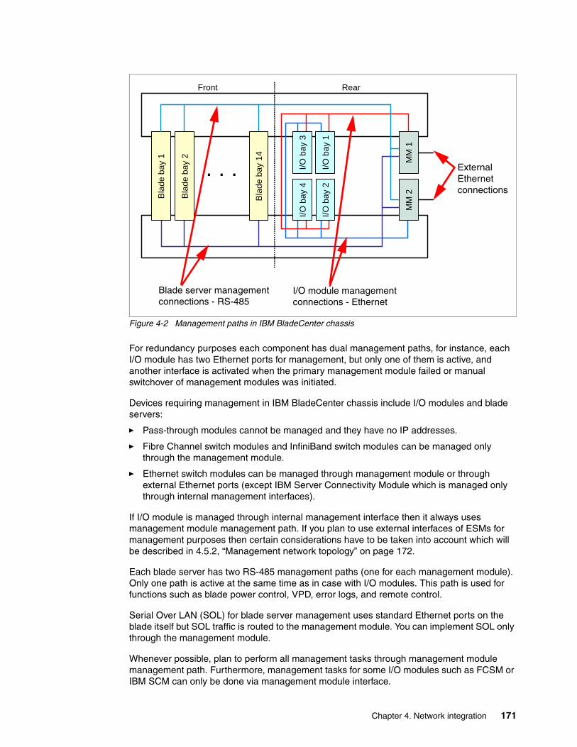
Chapter 4. Network integration 171
Figure 4-2 Management paths in IBM BladeCenter chassis
For redundancy purposes each component has dual management paths, for instance, each I/O module has two Ethernet ports for management, but only one of them is active, and another interface is activated when the primary management module failed or manual switchover of management modules was initiated.
Devices requiring management in IBM BladeCenter chassis include I/O modules and blade servers:
� Pass-through modules cannot be managed and they have no IP addresses.
� Fibre Channel switch modules and InfiniBand switch modules can be managed only through the management module.
� Ethernet switch modules can be managed through management module or through external Ethernet ports (except IBM Server Connectivity Module which is managed only through internal management interfaces).
If I/O module is managed through internal management interface then it always uses management module management path. If you plan to use external interfaces of ESMs for management purposes then certain considerations have to be taken into account which will be described in 4.5.2, “Management network topology” on page 172.
Each blade server has two RS-485 management paths (one for each management module). Only one path is active at the same time as in case with I/O modules. This path is used for functions such as blade power control, VPD, error logs, and remote control.
Serial Over LAN (SOL) for blade server management uses standard Ethernet ports on the blade itself but SOL traffic is routed to the management module. You can implement SOL only through the management module.
Whenever possible, plan to perform all management tasks through management module management path. Furthermore, management tasks for some I/O modules such as FCSM or IBM SCM can only be done via management module interface.
I/O b
ay 3
I/O b
ay 1
I/O b
ay 4
I/O b
ay 2
Bla
de b
ay 1
MM
2M
M 1
Bla
de b
ay 2
Bla
de b
ay 1
4
. . .
Front Rear
Blade server management connections - RS-485
I/O module management connections - Ethernet
External Ethernet connections
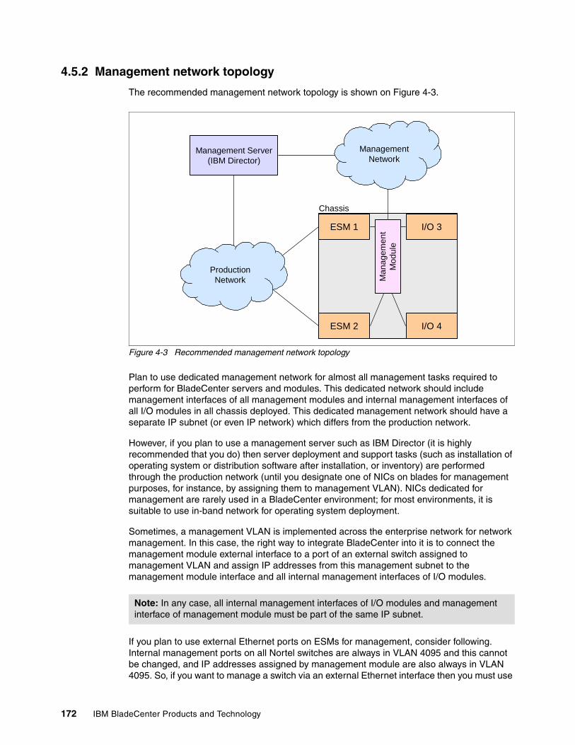
172 IBM BladeCenter Products and Technology
4.5.2 Management network topology
The recommended management network topology is shown on Figure 4-3.
Figure 4-3 Recommended management network topology
Plan to use dedicated management network for almost all management tasks required to perform for BladeCenter servers and modules. This dedicated network should include management interfaces of all management modules and internal management interfaces of all I/O modules in all chassis deployed. This dedicated management network should have a separate IP subnet (or even IP network) which differs from the production network.
However, if you plan to use a management server such as IBM Director (it is highly recommended that you do) then server deployment and support tasks (such as installation of operating system or distribution software after installation, or inventory) are performed through the production network (until you designate one of NICs on blades for management purposes, for instance, by assigning them to management VLAN). NICs dedicated for management are rarely used in a BladeCenter environment; for most environments, it is suitable to use in-band network for operating system deployment.
Sometimes, a management VLAN is implemented across the enterprise network for network management. In this case, the right way to integrate BladeCenter into it is to connect the management module external interface to a port of an external switch assigned to management VLAN and assign IP addresses from this management subnet to the management module interface and all internal management interfaces of I/O modules.
If you plan to use external Ethernet ports on ESMs for management, consider following. Internal management ports on all Nortel switches are always in VLAN 4095 and this cannot be changed, and IP addresses assigned by management module are also always in VLAN 4095. So, if you want to manage a switch via an external Ethernet interface then you must use
Note: In any case, all internal management interfaces of I/O modules and management interface of management module must be part of the same IP subnet.
ESM 1
ESM 2
I/O 3
I/O 4
Chassis
Man
agem
ent
Mod
ule
ManagementNetwork
ProductionNetwork
Management Server(IBM Director)
Chapter 4. Network integration 173
different VLAN on switch and assign IP address to that VLAN from subnet other than management.
Cisco Systems ESMs use slightly different approach. They use management VLAN for internal management interfaces and this VLAN can be changed, but internal interfaces will always belong to the new management VLAN. So, if you want to manage switch through external Ethernet interfaces then you must use different VLAN and assign IP address to that VLAN from subnet other than management.
It is highly recommended you use a dedicated management server (such as IBM Director) for centralized systems management. That server should have at least two network interfaces: one for management network and one for production network (unless all management tasks are performed through dedicated management network).
If you plan to use advanced deployment tools such as RDM then some requirements have to be met especially in case of routed network. For instance, if management server and deployed servers are on different subnets then routers between them must support DHCP relay. If you use multicast traffic for deployment then routers must support IGMP. Refer to the documentation of your systems management software for additional information.
4.5.3 Management protocols and tools
When planning to implement a BladeCenter solution consider using the following management tools for deployment, monitoring, maintenance, support, and optimization tasks:
� For the management of individual servers and modules, the simplest (from implementation and not from usage point of view) way is to use standard telnet or Web-based management for I/O modules.
� For the management of a group of I/O modules, use the available advanced management tools, such as BladeHarmony Manager from Blade Network Technologies for centralized management of Nortel ESMs using SNMP, or SAN Surfer for managing QLogic FC switch modules.
� Plan to implement IBM Director for BladeCenter management. IBM Director together with Remote Deployment Manager can provide a smart and powerful way of managing your entire infrastructure including servers, switches, and even certain storage systems from IBM.
� IBM BladeCenter management can also be integrated into enterprise management systems such as Tivoli®.
Note: It is not possible to use the same IP address for both external and internal management on all ESMs. You must use IP addresses from different subnets: one address for management through management module, other address for management through external Ethernet ports.

174 IBM BladeCenter Products and Technology
© Copyright IBM Corp. 2007. All rights reserved. 175
Chapter 5. Storage integration
IBM BladeCenter offer several possibilities of integration into storage infrastructure, such as SAN or iSCSI. This chapter will cover major considerations that should be taken into account during IBM BladeCenter storage infrastructure planning. They are storage system interoperability, switch module selection and interoperability rules, performance, high availability and redundancy, backup, boot from SAN, and others.
The following topics will be discussed:
� “Storage system interoperability” on page 176
� “Switch selection and interoperability rules” on page 176
� “High availability and redundancy” on page 178
� “Performance” on page 179
� “Backup solutions” on page 179
� “Boot from SAN” on page 183
� “iSCSI solutions” on page 184
5
176 IBM BladeCenter Products and Technology
5.1 Storage system interoperability
In general, if IBM BladeCenter is integrated into FC storage fabric then ensure that following requirements are met. Check the compatibility guides from storage system vendor for confirmation.
� IBM BladeCenter server hardware and HBA are supported by storage system
� FC fabric used or proposed to use is supported by storage system
� Operating systems deployed are supported both by IBM blades and the storage system
� Multipath drivers exist and are supported by the operating system and storage system (in case you plan for redundancy)
If any of these requirements are not met then consider proposing another solution that is supported.
Refer to the following publications for additional information:
� DS4000 interoperability matrix
� IBM Redbook IBM BladeCenter 4Gb SAN Solution, SG24-7313
5.2 Switch selection and interoperability rules
IBM BladeCenter provides integrated FC switching functionality by using several switch options (see 2.8, “Fibre Channel switch modules” on page 81):
� Brocade 10 and 20 port 4 Gb Fibre Channel Switch Modules (32R1813 and 32R1812)
� QLogic 10 and 20 port 4 Gb Fibre Channel Switch Modules (32R1904 and 26R0881)
� McDATA 10 and 20 port 4 Gb Fibre Channel Switch Modules (32R1905 and 32R1833)
Optical Pass-thru Module can be used in case when IBM BladeCenter have to be connected directly to external FC enterprise switch. Remember, that OPM can only support 2 Gb FC and not 4 Gb FC.
First and the most important thing during planning is to select right switch module that can provide required functionality together with seamless integration into existing client’s storage infrastructure (see Table 5-1).
Table 5-1 Fibre Channel Switch Module (FCSM) feature comparison
Brocade FCSM QLogic FCSM McDATA FCSM
Functionality
Basic FC connectivity, standards-based Yes Yes Yes
Advanced FC connectivity Yes No No
Interoperability (existing fabric)
Brocade interoperability Yes No No
QLogic interoperability Yes Yes No
McDATA interoperability No Noa
a. Optional McDATA Mode Firmware Upgrade is available
Yes

Chapter 5. Storage integration 177
“Yes” in the “Interoperability” portion of table means that feature is supported without any restrictions for existing fabric, but with restrictions for added fabric, and vice versa. “No” does not necessarily means that it is not supported but in that case severe restrictions apply to the existing fabric, that is, some functions of the existing fabric potentially have to be disabled (if they were used).
For example, if we integrate Brocade FCSM into QLogic fabric then we are not be able to use Brocade Advanced Fabric Services such as ISL trunking, at the same time QLogic fabric does not loose functionality. And vice versa, if we integrate QLogic fabric into existing Brocade fabric then we should place all Brocade switches in interoperability mode thus loosing Advanced Fabric Services functionality. Interoperability mode is a special mode used for integration of different vendor’s FC fabrics into one, and only standards-based functionality is available in the interoperability mode
If you plan to integrate IBM BladeCenter into a Fibre Channel fabric which is not listed here (for instance, Cisco), then QLogic could be a good choice (but remember, this is possible with interoperability mode only, so extended functionality will not be supported) or Optical Pass-thru could be an option.
So the rules for switch selection and interoperability can be summarized as follows:
� McDATA FCSM is basically used when IBM BladeCenter is integrated into existing McDATA fabric
� QLogic FCSM is essentially used when IBM BladeCenter is integrated into existing QLogic fabric or when basic FC functionality is required, that is, with one IBM BladeCenter with a directly connected storage server
� Brocade FCSM is used when IBM BladeCenter is integrated into existing Brocade fabric or when advanced FC connectivity is required, such as several chassis connected to high performance storage systems
If you plan to used advanced features such as ISL trunking then you may need to acquire specific licenses for these features.
If IBM BladeCenter is attached to non-IBM storage system then support for that configuration should be provided by the storage system’s vendor. Even if non-IBM storage is listed on IBM ServerProven which means that configuration has been tested but IBM will not provide support for it, and support is provided by third party vendor.
Refer to the vendor’s compatibility information for supported configurations. For IBM storage, refer to “Interoperability matrix” documents at:
http://www.stroage.ibm.com
For instance, DS4000™ interoperability matrix can be found at:
http://www.ibm.com/servers/storage/disk/ds4000/interop-matrix.html
In addition you can check IBM ServerProven for a list of supported configurations at:
http://www.ibm.com/servers/eserver/serverproven/compat/us/eserver.html
Additional information can be found in following publications:
� IBM Redbook IBM BladeCenter 4Gb SAN Solution, SG24-7313
Note: We highly recommend to use FC storage fabric from the same vendor to avoid possible operational, management, and troubleshooting issues.
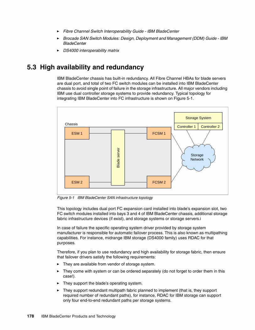
178 IBM BladeCenter Products and Technology
� Fibre Channel Switch Interoperability Guide - IBM BladeCenter
� Brocade SAN Switch Modules: Design, Deployment and Management (DDM) Guide - IBM BladeCenter
� DS4000 interoperability matrix
5.3 High availability and redundancy
IBM BladeCenter chassis has built-in redundancy. All Fibre Channel HBAs for blade servers are dual port, and total of two FC switch modules can be installed into IBM BladeCenter chassis to avoid single point of failure in the storage infrastructure. All major vendors including IBM use dual controller storage systems to provide redundancy. Typical topology for integrating IBM BladeCenter into FC infrastructure is shown on Figure 5-1.
Figure 5-1 IBM BladeCenter SAN infrastructure topology
This topology includes dual port FC expansion card installed into blade’s expansion slot, two FC switch modules installed into bays 3 and 4 of IBM BladeCenter chassis, additional storage fabric infrastructure devices (if exist), and storage systems or storage servers.i
In case of failure the specific operating system driver provided by storage system manufacturer is responsible for automatic failover process. This is also known as multipathing capabilities. For instance, midrange IBM storage (DS4000 family) uses RDAC for that purposes.
Therefore, if you plan to use redundancy and high availability for storage fabric, then ensure that failover drivers satisfy the following requirements:
� They are available from vendor of storage system.
� They come with system or can be ordered separately (do not forget to order them in this case!).
� They support the blade’s operating system.
� They support redundant multipath fabric planned to implement (that is, they support required number of redundant paths), for instance, RDAC for IBM storage can support only four end-to-end redundant paths per storage systems.
Chassis
ESM 1
FCSM 2
StorageNetwork
FCSM 1
ESM 2
Controller 1 Controller 2
Storage SystemB
lade
ser
ver
Chapter 5. Storage integration 179
Refer to storage system vendor’s documentation for additional information.
5.4 Performance
Performance can be an important factor during FC infrastructure planning. You have to consider to provide required end-to-end performance for your SAN. This can be done in several ways.
First, storage system’s failover driver can provide functionality of load balancing across redundant paths in addition to high availability. For instance, IBM System Storage Multi-path Subsystem Device Driver (SDD) used with DS6000™ and DS8000™ provides this functionality. If you plan to use that drivers then ensure that these drivers satisfy the following requirements:
� They are available from vendor of storage system.
� They come with system or can be ordered separately.
� They support blade’s operating system.
� They support multipath fabric planned to implement (that is, they support required number of paths implemented).
Second, you can use static LUN distribution between two storage controllers in storage system, that is, some LUNs will be served by controller 1 and others by controller 2. Zoning technique can also be used together with static LUN distribution in case you have redundant connections between FC switches and storage system’s controllers.
And last, you may have to implement trunking between FC switches to increase network bandwidth thus increasing performance. Trunks in the FC network are the same concept as in standard Ethernet networks, that is, several physical links between switches are grouped into one logical link with increased bandwidth. This is typically done when IBM BladeCenter is integrated into existing advanced FC infrastructure. But remember, that not all FC switches support trunking (only Brocade can do that), and this is an optional feature requiring additional license to be purchased.
Refer to storage system vendor’s documentation and to switch’s vendor documentation for additional information.
5.5 Backup solutions
Backup is one of the most important parts of IBM BladeCenter solution. First, you need to decide which kind of tape backup solution will be implemented. The valid IBM BladeCenter possibilities are as follows. See 5.5.1, “Dedicated server for centralized LAN backup” on page 180 for details.
� Centralized LAN backup with dedicated backup server (blade in chassis) with SCSI-attached tape autoloader or tape library
� Centralized LAN backup with dedicated backup server (blade in chassis) with FC-attached tape autoloader or tape library
� Centralized LAN backup with dedicated backup server (non-blade) with SCSI-attached tape drive, autoloader or tape library
� Centralized LAN backup with dedicated backup server (non-blade) with FC-attached tape autoloader or tape library
180 IBM BladeCenter Products and Technology
� LAN free backup with FC-attached tape autoloader or library - see 5.5.2, “LAN free backup for blades” on page 182.
If you plan to use blade server as a dedicated backup server or LAN free backup for blades then you must use only certified tape autoloaders and tape libraries (see IBM ServerProven for list of supported tape devices for specific blades). If you plan to use dedicated backup server on a non-blade system then you should use tape devices which are certified for that server. Check also that selected tape device and kind of backup are supported with proposed backup software.
5.5.1 Dedicated server for centralized LAN backup
The simplest way to provide backup for blades is to use blade or non-blade server with SCSI- or FC-attached tape unit. In this case all blade servers requiring backup will have backup agents, and backup traffic from these agents to the backup server will use standard LAN paths.
If you use FC-attached tape drive then it should be connected to FC fabric (or at least HBA) dedicated for backup, and should not be connected to the FC fabric carrying disk traffic. If it is not possible to use dedicated switches for that then use zoning techniques on FC switches to separate these two fabrics.
So, if you plan to use the blade server as a dedicated backup server with FC-attached tape then you use either one port of FC expansion card for tape and another for disk (there is no redundancy in this case), or you must use blade’s Storage and I/O Expansion Unit (or Memory and I/O expansion for HS21 or MultiProcessor Expansion for LS41, it depends on blade servers used) for additional FC ports to separate traffic and to provide redundancy.
If you plan to use the blade server as a dedicated backup server with SCSI-attached tape then you must use PCI Expansion Unit II (25K8373), IBM Ultra320 SCSI Controller 2 (39R8743), and tape connected to this controller. Refer to the Table 3-55 on page 159 for list of blades supporting PCI Expansion Unit II.
Possible topologies and traffic flows for LAN backups and FC-attached storage devices are shown on Figure 5-2 on page 181 and Figure 5-3 on page 182.
Note: We strongly recommend not to mix disk storage and tape storage on the same FC HBA. If you experience issues with your SAN and the root of these issues will be the tape and disk on the same HBA, IBM will recommend separating these devices.
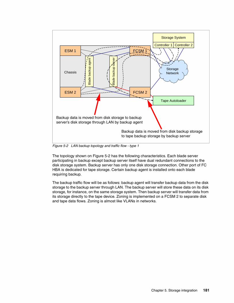
Chapter 5. Storage integration 181
Figure 5-2 LAN backup topology and traffic flow - type 1
The topology shown on Figure 5-2 has the following characteristics. Each blade server participating in backup except backup server itself have dual redundant connections to the disk storage system. Backup server has only one disk storage connection. Other port of FC HBA is dedicated for tape storage. Certain backup agent is installed onto each blade requiring backup.
The backup traffic flow will be as follows: backup agent will transfer backup data from the disk storage to the backup server through LAN. The backup server will store these data on its disk storage, for instance, on the same storage system. Then backup server will transfer data from its storage directly to the tape device. Zoning is implemented on a FCSM 2 to separate disk and tape data flows. Zoning is almost like VLANs in networks.
Chassis
Bla
de b
acku
p ag
ent
ESM 1
Bla
de b
acku
p se
rver
Tape Autoloader
FCSM 2
StorageNetwork
FCSM 1
ESM 2
Controller 1 Controller 2
Storage System
Backup data is moved from disk storage to backup server’s disk storage through LAN by backup agent
Backup data is moved from disk backup storage to tape backup storage by backup server
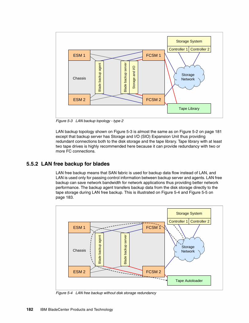
182 IBM BladeCenter Products and Technology
Figure 5-3 LAN backup topology - type 2
LAN backup topology shown on Figure 5-3 is almost the same as on Figure 5-2 on page 181 except that backup server has Storage and I/O (SIO) Expansion Unit thus providing redundant connections both to the disk storage and the tape library. Tape library with at least two tape drives is highly recommended here because it can provide redundancy with two or more FC connections.
5.5.2 LAN free backup for blades
LAN free backup means that SAN fabric is used for backup data flow instead of LAN, and LAN is used only for passing control information between backup server and agents. LAN free backup can save network bandwidth for network applications thus providing better network performance. The backup agent transfers backup data from the disk storage directly to the tape storage during LAN free backup. This is illustrated on Figure 5-4 and Figure 5-5 on page 183.
Figure 5-4 LAN free backup without disk storage redundancy
Chassis
Bla
de b
acku
p ag
ent
ESM 1
ESM 2
Sto
rage
and
I/O
Bla
de b
acku
p se
rver
Controller 1 Controller 2
Storage System
Tape Library
FCSM 2
StorageNetwork
FCSM 1
Chassis
Bla
de b
acku
p ag
ent
ESM 1
Bla
de b
acku
p se
rver
Tape Autoloader
FCSM 2
StorageNetwork
FCSM 1
ESM 2
Controller 1 Controller 2
Storage System
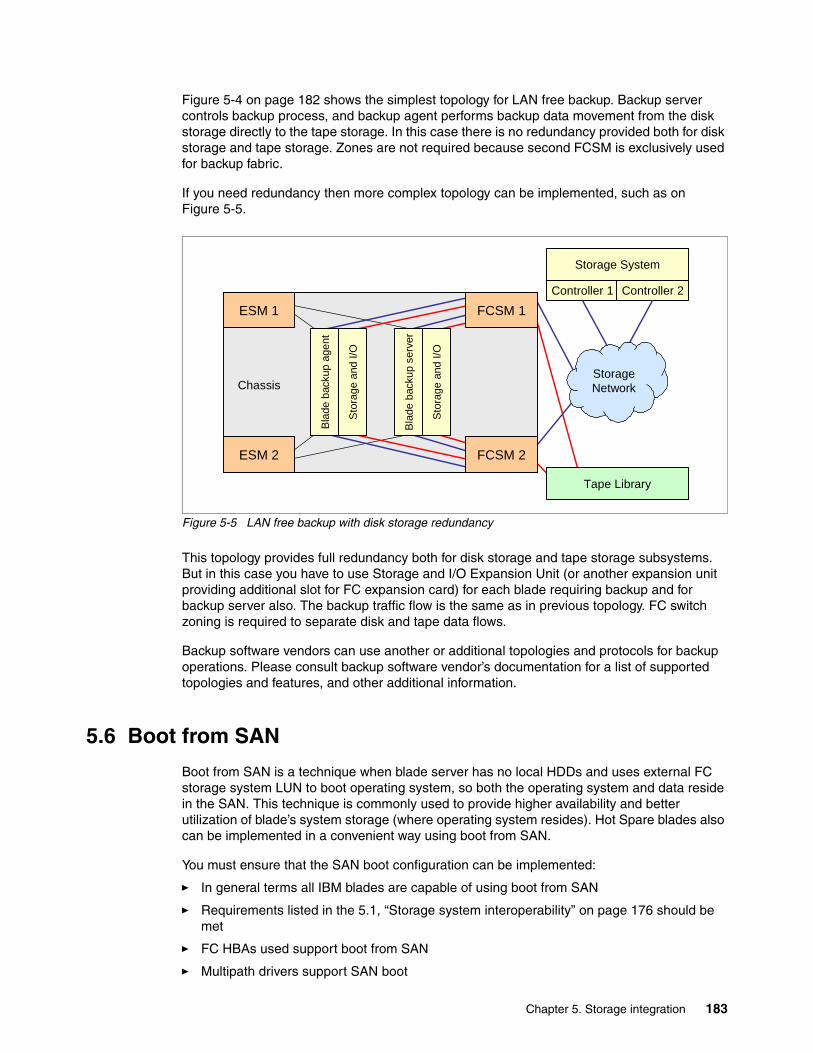
Chapter 5. Storage integration 183
Figure 5-4 on page 182 shows the simplest topology for LAN free backup. Backup server controls backup process, and backup agent performs backup data movement from the disk storage directly to the tape storage. In this case there is no redundancy provided both for disk storage and tape storage. Zones are not required because second FCSM is exclusively used for backup fabric.
If you need redundancy then more complex topology can be implemented, such as on Figure 5-5.
Figure 5-5 LAN free backup with disk storage redundancy
This topology provides full redundancy both for disk storage and tape storage subsystems. But in this case you have to use Storage and I/O Expansion Unit (or another expansion unit providing additional slot for FC expansion card) for each blade requiring backup and for backup server also. The backup traffic flow is the same as in previous topology. FC switch zoning is required to separate disk and tape data flows.
Backup software vendors can use another or additional topologies and protocols for backup operations. Please consult backup software vendor’s documentation for a list of supported topologies and features, and other additional information.
5.6 Boot from SAN
Boot from SAN is a technique when blade server has no local HDDs and uses external FC storage system LUN to boot operating system, so both the operating system and data reside in the SAN. This technique is commonly used to provide higher availability and better utilization of blade’s system storage (where operating system resides). Hot Spare blades also can be implemented in a convenient way using boot from SAN.
You must ensure that the SAN boot configuration can be implemented:
� In general terms all IBM blades are capable of using boot from SAN
� Requirements listed in the 5.1, “Storage system interoperability” on page 176 should be met
� FC HBAs used support boot from SAN
� Multipath drivers support SAN boot
Chassis
Bla
de b
acku
p ag
ent
ESM 1
ESM 2
Sto
rage
and
I/O
Sto
rage
and
I/O
Bla
de b
acku
p se
rver
Controller 1 Controller 2
Storage System
Tape Library
FCSM 2
StorageNetwork
FCSM 1
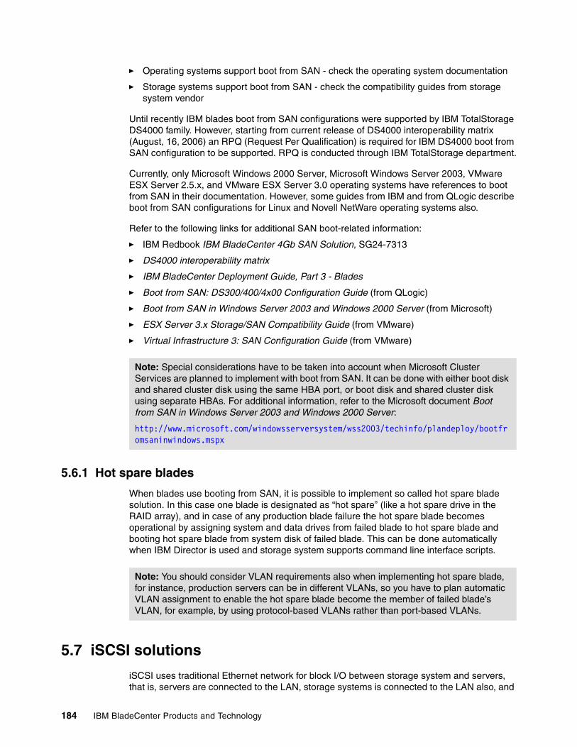
184 IBM BladeCenter Products and Technology
� Operating systems support boot from SAN - check the operating system documentation
� Storage systems support boot from SAN - check the compatibility guides from storage system vendor
Until recently IBM blades boot from SAN configurations were supported by IBM TotalStorage DS4000 family. However, starting from current release of DS4000 interoperability matrix (August, 16, 2006) an RPQ (Request Per Qualification) is required for IBM DS4000 boot from SAN configuration to be supported. RPQ is conducted through IBM TotalStorage department.
Currently, only Microsoft Windows 2000 Server, Microsoft Windows Server 2003, VMware ESX Server 2.5.x, and VMware ESX Server 3.0 operating systems have references to boot from SAN in their documentation. However, some guides from IBM and from QLogic describe boot from SAN configurations for Linux and Novell NetWare operating systems also.
Refer to the following links for additional SAN boot-related information:
� IBM Redbook IBM BladeCenter 4Gb SAN Solution, SG24-7313
� DS4000 interoperability matrix
� IBM BladeCenter Deployment Guide, Part 3 - Blades
� Boot from SAN: DS300/400/4x00 Configuration Guide (from QLogic)
� Boot from SAN in Windows Server 2003 and Windows 2000 Server (from Microsoft)
� ESX Server 3.x Storage/SAN Compatibility Guide (from VMware)
� Virtual Infrastructure 3: SAN Configuration Guide (from VMware)
5.6.1 Hot spare blades
When blades use booting from SAN, it is possible to implement so called hot spare blade solution. In this case one blade is designated as “hot spare” (like a hot spare drive in the RAID array), and in case of any production blade failure the hot spare blade becomes operational by assigning system and data drives from failed blade to hot spare blade and booting hot spare blade from system disk of failed blade. This can be done automatically when IBM Director is used and storage system supports command line interface scripts.
5.7 iSCSI solutions
iSCSI uses traditional Ethernet network for block I/O between storage system and servers, that is, servers are connected to the LAN, storage systems is connected to the LAN also, and
Note: Special considerations have to be taken into account when Microsoft Cluster Services are planned to implement with boot from SAN. It can be done with either boot disk and shared cluster disk using the same HBA port, or boot disk and shared cluster disk using separate HBAs. For additional information, refer to the Microsoft document Boot from SAN in Windows Server 2003 and Windows 2000 Server:
http://www.microsoft.com/windowsserversystem/wss2003/techinfo/plandeploy/bootfromsaninwindows.mspx
Note: You should consider VLAN requirements also when implementing hot spare blade, for instance, production servers can be in different VLANs, so you have to plan automatic VLAN assignment to enable the hot spare blade become the member of failed blade’s VLAN, for example, by using protocol-based VLANs rather than port-based VLANs.

Chapter 5. Storage integration 185
they use SCSI over IP protocol (iSCSI) to communicate with each other. Because iSCSI uses standard TCP/IP stack it is possible to use iSCSI connections across LAN, MAN, or even WAN connections.
In general iSCSI can be implemented in two ways: using software iSCSI initiator or using hardware iSCSI initiator.
� A software iSCSI initiator is an operating system’s driver that provides iSCSI capabilities for standard Ethernet NICs. Software initiators can be obtained from the operating system vendor, for instance, Microsoft has Software iSCSI Initiator available for download.
� A hardware iSCSI initiator is a separate expansion card that provides processing of iSCSI protocol in dedicated hardware. IBM offers hardware iSCSI initiator - QLogic iSCSI Expansion Card for IBM BladeCenter (32R1923). It is possible to boot from iSCSI when using hardware iSCSI initiator.
If you plan for redundancy then you have to use multipath drivers. Generally, they are provided by the operating system vendor for iSCSI implementations, even if you plan to use hardware initiators.
It is possible to implement HA clustering solutions using iSCSI, but certain restrictions may apply (check the storage system vendor’s compatibility guides). For instance, Microsoft Cluster Services are not supported with multipathing for IBM iSCSI solutions (DS300 and N 3700).
When planning iSCSI solution consider the following:
� IBM blade hardware, initiators, and operating system should be supported by iSCSI storage system - check the compatibility guides from storage vendor.
� Multipath drivers exist and are supported by operating system and storage system (in case of plan for redundancy) - check the compatibility guides from the storage vendor and operating system vendor.
You can find additional information in the following publications:
� IBM Redpaper IBM BladeCenter iSCSI SAN Solution, REDP-4153
� IBM System Storage N series interoperability matrix
� Microsoft Support for iSCSI (from Microsoft)
Note: It is highly recommended that you use a separate network segment for iSCSI traffic, that is, NICs, switches (or VLANs), and storage system ports participating in iSCSI communications should be isolated from other traffic.

186 IBM BladeCenter Products and Technology
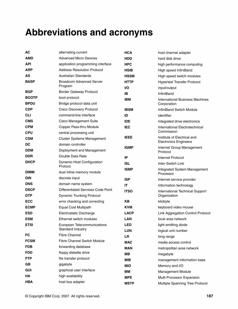
© Copyright IBM Corp. 2007. All rights reserved. 187
AC alternating current
AMD Advanced Micro Devices
API application programming interface
ARP Address Resolution Protocol
AS Australian Standards
BASP Broadcom Advanced Server Program
BGP Border Gateway Protocol
BOOTP boot protocol
BPDU Bridge protocol data unit
CDP Cisco Discovery Protocol
CLI command-line interface
CMS Cisco Management Suite
CPM Copper Pass-thru Module
CPU central processing unit
CSM Cluster Systems Management
DC domain controller
DDM Deployment and Management
DDR Double Data Rate
DHCP Dynamic Host Configuration Protoco
DIMM dual inline memory module
DIN discrete input
DNS domain name system
DSCP Differentiated Services Code Point
DTP Dynamic Trunking Protocol
ECC error checking and correcting
ECMP Equal Cost Multipath
ESD Electrostatic Discharge
ESM Ethernet switch modules
ETSI European Telecommunications Standard Industry
FC Fibre Channel
FCSM Fibre Channel Switch Module
FDB forwarding database
FDD floppy diskette drive
FTP file transfer protocol
GB gigabyte
GUI graphical user interface
HA high availability
HBA host bus adapter
Abbreviations and acronyms
HCA host channel adapter
HDD hard disk drive
HPC high performance computing
HSIB High speed InfiniBand
HSSM High speed switch modules
HTTP Hypertext Transfer Protocol
I/O input/output
IB InfiniBand
IBM International Business Machines Corporation
IBSM InfiniBand Switch Module
ID identifier
IDE integrated drive electronics
IEC International Electrotechnical Commission
IEEE Institute of Electrical and Electronics Engineers
IGMP Internet Group Management Protocol
IP Internet Protocol
ISL Inter-Switch Link
ISMP Integrated System Management Processor
ISP Internet service provider
IT information technology
ITSO International Technical Support Organization
KB kilobyte
KVM keyboard video mouse
LACP Link Aggregation Control Protocol
LAN local area network
LED light emitting diode
LUN logical unit number
LR long range
MAC media access control
MAN metropolitan area network
MB megabyte
MIB management information base
MIO Memory and I/O
MM Management Module
MPE Multi Processor Expansion
MSTP Multiple Spanning Tree Protocol
188 IBM BladeCenter Products and Technology
MVR Multicast VLAN registration
NDCLA Non-Disruptive Code Load Activation
NEBS network equipment building system
NIC network interface card
NOS network operating system
NTP Network Time Protocol
OPM Optical Pass-thru Module
OS operating system
OSPF Open Shortest Path First
PCI Peripheral Component Interconnect
PDU power distribution unit
PFA Predictive Failure Analysis
PVST Per-VLAN Spanning Tree
RADIUS Remote Authentication Dial In User Service
RAID redundant array of independent disks
RAM random access memory
RDAC Redundant Disk Array Controller
RDIMM registered DIMM
RDM Remote Deployment Manager
RDMA Remote Direct Memory Access
RHEL Red Hat Enterprise Linux
RIP Routing Information Protocol
RMON Remote Monitoring
RPQ Request Per Qualification
RSA Remote Supervisor Adapter
RSCN Registered State Change Notification
RSTP Rapid Spanning Tree Protocol
RTSP Real time streaming protocol
SAN storage area network
SAS Serial Attached SCSI
SCM Supply Chain Management
SCSI small computer system interface
SDD Subsystem Device Driver
SDRAM static dynamic RAM
SFF Small Form Factor
StFF Standard Form Factor
SFP small form-factor pluggable
SIMD single instruction multiple data
SIO Storage and I/O
SLES SUSE LINUX Enterprise Server
SNMP Simple Network Management Protocol
SOL Serial over LAN
SR short range
SSH Secure Shell
SSL Secure Sockets Layer
STP Spanning Tree Protocol
TACACS Terminal Access Controller Access Control System
TCO total cost of ownership
TCP Transmission Control Protocol
TCP/IP Transmission Control Protocol/Internet Protocol
TFTP Trivial File Transfer Protocol
TOE TCP offload engine
UDLD UniDirectional link detection
USB universal serial bus
UTP unshielded twisted pair
VGA video graphics array
VIOS Virtual I/O Server
VLAN Virtual LAN
VLP very low profile
VMPS VLAN Membership Policy Server
VOIP Voice over Internet Protcol
VPD vital product data
VRRP virtual router redundancy protocol
VTP VLAN Trunking Protocol
WAN wide area network
WRR weighted round-robin
© Copyright IBM Corp. 2007. All rights reserved. 189
Related publications
The publications listed in this section are considered particularly suitable for a more detailed discussion of the topics covered in this Redpaper.
IBM RedbooksFor information about ordering these publications, see “How to get IBM Redbooks” on page 198. Note that some of the documents referenced here may be available in softcopy only.
� IBM System Storage Solutions Handbook, SG24-5250
� Integrating IBM Director with Enterprise Management Solutions, SG24-5388
� Introduction to Storage Area Networks, SG24-5470
� IBM TotalStorage: Implementing an Open IBM SAN, SG24-6116
� Implementing IBM Director 5.10, SG24-6188
� The IBM eServer BladeCenter JS20, SG24-6342
� IBM eServer xSeries and BladeCenter Server Management, SG24-6495
� IBM BladeCenter 4Gb SAN Solution, SG24-7313
� Nortel Networks L2/3 Ethernet Switch Module for IBM eServer BladeCenter, REDP-3586
� IBM eServer BladeCenter Networking Options, REDP-3660
� IBM eServer BladeCenter Layer 2-7 Network Switching, REDP-3755
� Cisco Systems Intelligent Gigabit Ethernet Switch Module for the IBM eServer BladeCenter, REDP-3869
� IBM eServer BladeCenter and Topspin InfiniBand Switch Technology, REDP-3949
� IBM BladeCenter iSCSI SAN Solution, REDP-4153
Product publications
BladeCenter 8677 publications� Acoustical Attenuation Module User's Guide:
http://www.ibm.com/systems/support/supportsite.wss/docdisplay?brandind=5000020&lndocid=MIGR-45155
� IBM eServer BladeCenter Power Module Upgrade Guidelines:
http://www.ibm.com/systems/support/supportsite.wss/docdisplay?brandind=5000020&lndocid=MIGR-53353
Nortel Networks L2/3 Copper GbE Switch Module� Nortel Networks Layer 2/3 GbE Switch Module Alteon OS 21.0 Release Notes
http://www.ibm.com/systems/support/supportsite.wss/docdisplay?brandind=5000020&lndocid=MIGR-58337
190 IBM BladeCenter Products and Technology
� Nortel Networks Layer 2/3 GbE Switch Module Installation Guide
http://www.ibm.com/systems/support/supportsite.wss/docdisplay?brandind=5000020&lndocid=MIGR-58334
� Nortel Networks Layer 2/3 GbE Switch Module Alteon OS 21.0 Application Guide
http://www.ibm.com/systems/support/supportsite.wss/docdisplay?brandind=5000020&lndocid=MIGR-58325
� Nortel Networks Layer 2/3 GbE Switch Module Alteon OS 21.0 Command Reference
http://www.ibm.com/systems/support/supportsite.wss/docdisplay?brandind=5000020&lndocid=MIGR-58326
� Nortel Networks Layer 2/3 GbE Switch Module Alteon OS 21.0 BBI Quick Guide
http://www.ibm.com/systems/support/supportsite.wss/docdisplay?brandind=5000020&lndocid=MIGR-58323
Cisco Systems Intelligent Gb Ethernet Switch Module� Cisco Systems Intelligent Gigabit Ethernet Switch Module for the IBM eServer
BladeCenter Release Notes
http://www.ibm.com/systems/support/supportsite.wss/docdisplay?brandind=5000020&lndocid=MIGR-55262
� Cisco Systems Intelligent Gigabit Ethernet Switch Module for the IBM eServer BladeCenter Installation Guide
http://www.ibm.com/systems/support/supportsite.wss/docdisplay?brandind=5000020&lndocid=MIGR-57858
� Cisco Systems Intelligent Gigabit Ethernet Switch Module for the IBM eServer BladeCenter Software Configuration Guide
http://www.ibm.com/systems/support/supportsite.wss/docdisplay?brandind=5000020&lndocid=MIGR-55261
� Cisco Systems Intelligent Gigabit Ethernet Switch Module for the IBM eServer BladeCenter System Command Reference
http://www.ibm.com/systems/support/supportsite.wss/docdisplay?brandind=5000020&lndocid=MIGR-55259
� Cisco Systems Intelligent Gigabit Ethernet Switch Module for the IBM eServer BladeCenter System Message Guide
http://www.ibm.com/systems/support/supportsite.wss/docdisplay?brandind=5000020&lndocid=MIGR-55259
Nortel Networks Layer 2-7 GbE Switch Module� Nortel Networks Layer 2-7 GbE Switch Module for IBM eServer BladeCenter Products:
Alteon OS 20.2 Release Notes
http://www.ibm.com/systems/support/supportsite.wss/docdisplay?brandind=5000020&lndocid=MIGR-54999
� Nortel Networks Layer 2-7 GbE Switch Module for IBM eServer BladeCenter Products: Installation Guide
http://www.ibm.com/systems/support/supportsite.wss/docdisplay?brandind=5000020&lndocid=MIGR-53065
Related publications 191
� Nortel Networks Layer 2-7 GbE Switch Module for IBM eServer BladeCenter Products: Alteon OS 20.2 Application Guide
http://www.ibm.com/systems/support/supportsite.wss/docdisplay?brandind=5000020&lndocid=MIGR-53098
� Nortel Networks Layer 2-7 GbE Switch Module for IBM eServer BladeCenter Products: Alteon OS 20.2 Browser-Based Interface Quick Guide
http://www.ibm.com/systems/support/supportsite.wss/docdisplay?brandind=5000020&lndocid=MIGR-53102
� Nortel Networks Layer 2-7 GbE Switch Module for IBM eServer BladeCenter Products: Alteon OS 20.2 Command Reference Edition B
http://www.ibm.com/systems/support/supportsite.wss/docdisplay?brandind=5000020&lndocid=MIGR-53101
Intel Gigabit Ethernet Switch Module for IBM BladeCenter T� Intel Gigabit Ethernet Switch Module for IBM eServer BladeCenter Installation Guide
http://www.ibm.com/systems/support/supportsite.wss/docdisplay?brandind=5000020&lndocid=MIGR-56746
� Intel Gigabit Ethernet Switch Module for IBM eServer BladeCenter User's Guide
http://www.ibm.com/systems/support/supportsite.wss/docdisplay?brandind=5000020&lndocid=MIGR-56745
� Intel Gigabit Ethernet Switch Module for IBM eServer BladeCenter Command Line Interface (CLI) Reference Guide
http://www.ibm.com/systems/support/supportsite.wss/docdisplay?brandind=5000020&lndocid=MIGR-56744
Copper Pass-thru Module� Copper Pass-thru Module Installation Guide
http://www.ibm.com/systems/support/supportsite.wss/docdisplay?brandind=5000020&lndocid=MIGR-57332
� Copper Pass-thru Module (CPM) Cable Installation Instructions
http://www.ibm.com/systems/support/supportsite.wss/docdisplay?brandind=5000020&lndocid=MIGR-59020
Optical Pass-thru Module� IBM eServer BladeCenter Optical Pass-thru Module Installation Guide:
http://www.ibm.com/systems/support/supportsite.wss/docdisplay?brandind=5000020&lndocid=MIGR-52864
� Troubleshooting Optical Pass-thru Module (OPM) (02R9080) issues:
http://www.ibm.com/systems/support/supportsite.wss/docdisplay?brandind=5000020&lndocid=MIGR-61155
IBM Server Connectivity Module� Server Connectivity Module for IBM BladeCenter User Guide at:
http://www.ibm.com/systems/support/supportsite.wss/docdisplay?brandind=5000020&lndocid=MIGR-64190
192 IBM BladeCenter Products and Technology
Management Modules� IBM eServer BladeCenter and BladeCenter Management Module User's Guide:
http://www.ibm.com/systems/support/supportsite.wss/docdisplay?brandind=5000020&lndocid=MIGR-45153
� Management Module Command Line Interface Reference Guide:
http://www.ibm.com/systems/support/supportsite.wss/docdisplay?brandind=5000020&lndocid=MIGR-54667
� IBM eServer BladeCenter and BladeCenter Management Module User's Guide:
http://www.ibm.com/systems/support/supportsite.wss/docdisplay?brandind=5000020&lndocid=MIGR-45153
� Management Module Command Line Interface Reference Guide:
http://www.ibm.com/systems/support/supportsite.wss/docdisplay?brandind=5000020&lndocid=MIGR-54667
� Management Processor Command Line Interface Utility Version 3.00:
http://www.ibm.com/systems/support/supportsite.wss/docdisplay?brandind=5000020&lndocid=MIGR-54216
Topspin Infiniband Switch Module� Topspin Infiniband Switch Module for BladeCenter User Guide:
http://www.ibm.com/systems/support/supportsite.wss/docdisplay?brandind=5000020&lndocid=MIGR-60200
Brocade Switch Modules� Brocade Enterprise/Entry SAN Switch Module for IBM eServer BladeCenter Installation
Guide:
http://www.ibm.com/systems/support/supportsite.wss/docdisplay?brandind=5000020&lndocid=MIGR-55363
� Brocade Fabric OS v4.4.1a Release Notes:
http://www.ibm.com/systems/support/supportsite.wss/docdisplay?brandind=5000020&lndocid=MIGR-55419
� Brocade SAN Switch Modules for IBM eServer BladeCenter: Design, Deployment and Management Guide DDM:
http://www.ibm.com/systems/support/supportsite.wss/docdisplay?brandind=5000020&lndocid=MIGR-55327
� Brocade Enterprise/Entry SAN Switch Module Installation Guide - IBM eServer BladeCenter:
http://www.ibm.com/systems/support/supportsite.wss/docdisplay?brandind=5000020&lndocid=MIGR-55363
� Multipath Subsystem Device Driver User's Guide at:
http://www.ibm.com/support/docview.wss?rs=503&context=HW26L&uid=ssg1S7000303
Related publications 193
McDATA Fibre Channel Switch Module� McDATA 6-Port Fibre Channel Switch Module for IBM eServer BladeCenter Installation
Guide:
http://www.ibm.com/systems/support/supportsite.wss/docdisplay?brandind=5000020&lndocid=MIGR-59840
� McDATA 6-Port Fibre Channel Switch Module for IBM eServer BladeCenter Management Guide:
http://www.ibm.com/systems/support/supportsite.wss/docdisplay?brandind=5000020&lndocid=MIGR-59910
Other BladeCenter publications� IBM eServer BladeCenter SAN Solutions Guide:
http://www.ibm.com/systems/support/supportsite.wss/docdisplay?brandind=5000020&lndocid=MIGR-54854
� Fibre Channel Switch Interoperability Guide Version 4.00:
http://www.ibm.com/systems/support/supportsite.wss/docdisplay?brandind=5000020&lndocid=MIGR-58206
� SAN Solutions Guide version 1.00 - IBM eServer:
http://www.ibm.com/systems/support/supportsite.wss/docdisplay?brandind=5000020&lndocid=MIGR-46241
Other publicationsThese publications are also relevant as further information sources:
� A Comparison of Single-Core and Dual-Core Opteron Processor Performance for HPC, Douglas M. Pase and Matthew A. Eckl
http://www.ibm.com/servers/eserver/opteron/benchmarks/wp.html
� Systems Management for IBM eServer xSeries and BladeCenter Servers - 2005, Mark T Chapman
http://www-306.ibm.com/common/ssi/apilite?infotype=SA&infosubt=WH&lastdays=1825&hitlimit=200&ctvwcode=US&pubno=XSW0*USEN,XSL0*USEN&appname=STG_XS_USEN_WH&additional=summary&contents=keeponlit
or
ftp://ftp.software.ibm.com/common/ssi/rep_wh/n/XSW01280USEN/XSW01280USEN.PDF
� IBM BladeCenter Deployment Guide, Chris Gillen, Sam Litenatsky, Kevin Conover
http://www.ibm.com/support/docview.wss?uid=tss1wp100564
� BladeCenter processor blades, I/O expansion adapters, and units, J. E. Hughes, M. L. Scollard, R. Land, J. Parsonese, C. C. West, V. A. Stankevich, C. L. Purrington, D. Q. Hoang, G. R. Shippy, M. L. Loeb, M. W. Williams, B. A. Smith, D. M. Desaiet al, IBM Journal of Research & Development, Vol. 49, No. 6, 837-859, November 2005
http://www.research.ibm.com/journal/rd49-6.html
� BladeCenter T system for the telecommunicatinons industry, S. L. Vanderlinden, B. O. Anthony, G. D. Batalden, B. K. Gorti, J. Lloyd, J. Macon, Jr., G. Pruett, B. A. Smith, IBM Journal of Research & Development, Vol. 49, No. 6, 873-885, November 2005
http://www.research.ibm.com/journal/rd49-6.html
194 IBM BladeCenter Products and Technology
� BladeCenter chassis management, T. Brey, B. E. Bigelow, J. E. Bolan, H. Cheselka, Z. Dayar, J. M. Franke, D. E. Johnson, R. N. Kantesaria, E. J. Klodnicki, S. Kochar, S. M. Lardinois, C. A. Morrell, M. S. Rollins, R. R. Wolford, D. R. Woodha, IBM Journal of Research & Development, Vol. 49, No. 6, 873-885, November 2005
http://www.research.ibm.com/journal/rd49-6.html
� BladeCenter systems management software, G. Pruett A. Abbondanzio, J. Bielski, T. D. Fadale, A. E. Merkin, Z. Rafalovich, L. A. Riedle, J. W. Simpson, IBM Journal of Research & Development, Vol. 49, No. 6, 873-885, November 2005
http://www.research.ibm.com/journal/rd49-6.html
� BladeCenter networking, S. W. Hunter, N. C. Strole, D. W. Cosby, D. M. Green, IBM Journal of Research & Development, Vol. 49, No. 6, 873-885, November 2005
http://www.research.ibm.com/journal/rd49-6.html
� BladeCenter packaging, power, and cooling, M. J. Crippen, R. K. Alo, D. Champion, R. M. Clemo, C. M. Grosser, N. J. Gruendler, M. S. Mansuria, J. A. Matteson, M. S. Miller, B. A. Trumbo, IBM Journal of Research & Development, Vol. 49, No. 6, 887-903, November 2005
http://www.research.ibm.com/journal/rd49-6.html
Online resourcesThese Web sites are also relevant as further information sources:
Product information� Benchmarks for the BladeCenter:
http://www.ibm.com/servers/eserver/bladecenter/benchmarks/
� BladeCenter announcement letters:
http://www-306.ibm.com/common/ssi/OIX.wss
� pSeries White papers:
http://www.ibm.com/servers/eserver/pseries/hardware/whitepapers/power4.html
� The IBM eServer xSeries Rack Configurator:
http://www.ibm.com/servers/eserver/xseries/library/configtools.html
� The Necessity of Change Management in the Intel Server Space at:
http://www.ibm.com/servers/eserver/xseries/literature/wp_lit.html
� Microsoft’s licensing policy on logical processors:
http://www.microsoft.com/licensing/highlights/multicore.mspx
� SCO certified and compatible hardware site at:
http://wdb1.caldera.com/chwp/owa/hch_search_wizard.screen
� Altiris Web site deployment solutions and alliance:
http://www.altiris.com/products/deploymentsol/http://www.altiris.com/partners/alliances/ibm/
� Cluster System Management documents:
http://publib.boulder.ibm.com/clresctr/windows/public/clusterbooks.html
Related publications 195
� IBM Dynamic System Analysis (DSA):
http://www.ibm.com/servers/eserver/xseries/systems_management/dsa.html
� IBM Storage Web site:
http://www.ibm.com/servers/storage/tape/
� Telcordia:
http://www.telcordia.com
� European Telecommunication Standards Institute (ETSI):
http://www.etsi.org
� HS40 onboard Intel NICs with Linux OS, use bonding driver:
http://downloadfinder.intel.com/scripts-df-external/Detail_Desc.aspx?agr=Y&DwnldID=5600&ProductID=61
� Using NIC Teaming Adapters with Network Load Balancing May Cause Network Problems
http://go.microsoft.com/fwlink/?LinkId=18366
� QLogic SAN Interoperability:
http://www.qlogic.com/interopguide/
� McData compatibility documents:
http://www.mcdata.com/support/sil
� Brocade SAN Interoperability:
http://www.brocade.com/products/interop/san-interop.jsp
� IBM Total Storage DS4000, refer to DS4000 interoperability matrix at:
http://www.ibm.com/servers/storage/disk/ds4000/interop-matrix.html
� Boot from SAN in Windows Server 2003 and Windows 2000 Server at:
http://www.microsoft.com/windowsserversystem/wss2003/techinfo/plandeploy/bootfromsaninwindows.mspx
� xSeries configurator tools:
http://www.pc.ibm.com/us/eserver/xseries/library/configtools.html
Technology� Intel Xeon DP:
http://www.intel.com/design/xeon/prodbref
� Intel Xeon Processor MP:
http://www.intel.com/design/xeon/xeonmp/prodbref
� Intel NetBurst architecture, see:
http://www.intel.com/cd/ids/developer/asmo-na/eng/44004.htm
� Windows-Based Servers and Intel Hyper-Threading Technology:
http://www.microsoft.com/windows2000/server/evaluation/performance/reports/hyperthread.asp
� HyperTransport and the HyperTransport Consortium:
http://www.hypertransport.org/
� Intel 64 Technology (EM64T):
http://www.intel.com/technology/64bitextensions/
http://downloadfinder.intel.com/scripts-df-external/Detail_Desc.aspx?agr=Y&DwnldID=5600&ProductID=61
196 IBM BladeCenter Products and Technology
ftp://ftp.software.ibm.com/eserver/benchmarks/wp_Dual_Core_072505.pdf
� 64-bit technology and performance:
http://www-03.ibm.com/servers/eserver/xseries/benchmarks/related.html
� PowerPC 970 and PowerPC 970FX microprocessors:
http://www.chips.ibm.com
� BCM570X Broadcom NetXtreme Gigabit Ethernet Teaming white paper:
http://www.broadcom.com/collateral/wp/570X-WP100-R.pdf
ServicesFor information about other available IBM Global Services and ITS services, see:
http://www.ibm.com/services/http://www.ibm.com/services/us/index.wss/gen_ithttp://www.pc.ibm.com/ww/eserver/xseries/services/index.html
� Sales Configuration Aid:
http://www.pc.ibm.com/support?page=MIGR-41411
� Warranty Service Upgrade options:
http://www.ibm.com/services/us/index.wss/offering/its/a1001480
� Maintenance Agreement options:
http://www.ibm.com/services/us/index.wss/offering/its/a1001505
� SPORE program:
http://exist.raleigh.ibm.com/spore/
� IBM Business Continuity And Consulting Services:
http://www.ibm.com/services/us/index.wss/of/bcrs/a1000387
Product support � IBM support for employees:
http://w3.ibm.com/support/assure
� IBM support for Business Partners:
http://www.ibm.com/partnerworld/techsupport http://www.ibm.com/partnerworld/pwhome.nsf/weblook/cpw_index.html
� IBM support for Asia Pacific:
http://w3.ibm.com/support/ap/
� xSeries Solution Assurance Trigger criteria:
http://w3.ibm.com/support/assure/assur30i.nsf/PubAllNum/SA200
� Software and device drivers matrix (chassis and blade servers):
http://www.ibm.com/systems/support/supportsite.wss/docdisplay?brandind=5000020&lndocid=MIGR-63017
� Troubleshooting Optical Pass-thru Module issues:
http://www.ibm.com/systems/support/supportsite.wss/docdisplay?brandind=5000020&lndocid=MIGR-61155

Related publications 197
� NEBS compatibility list:
http://www.ibm.com/systems/support/supportsite.wss/docdisplay?brandind=5000020&lndocid=MIGR-54720
� BladeCenter - Serial over LAN Setup Guide and Enabling and configuring SOL (Serial over LAN) on an 8842 Blade Server White paper available from:
http://www.ibm.com/servers/eserver/support/bladecenter/js20/installinghwonly.html
� UpdateXpress:
http://www.ibm.com/systems/support/supportsite.wss/docdisplay?brandind=5000016&lndocid=MIGR-53046
� IBM ServerGuide Scripting Toolkit:
http://www.ibm.com/systems/support/supportsite.wss/docdisplay?brandind=5000016&lndocid=MIGR-53564
� IBM Remote Deployment Manager 4.20 Compatibility Guide for compatibility:
http://www.ibm.com/systems/support/supportsite.wss/docdisplay?brandind=5000016&lndocid=MIGR-56662
� Remote Deployment Manager White papers:
http://www.ibm.com/systems/support/supportsite.wss/docdisplay?brandind=5000016&lndocid=MIGR-53487
� ServerGuide Scripting Toolkit User Reference Version 1.2.01:
http://www.ibm.com/systems/support/supportsite.wss/docdisplay?brandind=5000016&lndocid=MIGR-60190
� MegaRAID Configuration Console (HS20):
http://www.ibm.com/systems/support/supportsite.wss/docdisplay?brandind=5000020&lndocid=MIGR-52761
� ServeRAID Manager:
http://www.ibm.com/systems/support/supportsite.wss/docdisplay?brandind=5000008&lndocid=SERV-RAID
� IBM Director upward integration modules:
http://www.ibm.com/systems/support/supportsite.wss/docdisplay?brandind=5000016&lndocid=SERV-DIRECT
� Electronic Service Agent portal site xSeries - Director Extension:
http://www.ibm.com/services/electronic
� Intel Advanced Networking Services:
http://support.intel.com/support/network/sb/CS-009747.htm
� VMware support:
http://www.vmware.com/vmtn/resources/esx_resources.html
� Broadcom Advanced Server Program (BASP) is Broadcom Teaming driver:
http://www.ibm.com/systems/support/supportsite.wss/docdisplay?brandind=5000008&lndocid=MIGR-43815
� Intel PROSet is Intel teaming driver:
http://www.ibm.com/systems/support/supportsite.wss/docdisplay?brandind=5000008&lndocid=MIGR-54793
198 IBM BladeCenter Products and Technology
� Introduction to iSCSI in BladeCenter at:
http://www.ibm.com/systems/support/supportsite.wss/docdisplay?brandind=5000020&lndocid=MIGR-60300
� IBM eServer BladeCenter Switch Interoperability Guide:
http://www.ibm.com/systems/support/supportsite.wss/docdisplay?brandind=5000020&lndocid=MIGR-58206
� Remote SAN Boot for HS20 (8678/8832) and HS40 (8839)
http://www.ibm.com/systems/support/supportsite.wss/docdisplay?brandind=5000020&lndocid=MIGR-57563
� IBM eServer BladeCenter Remote SAN Boot - JS20:
http://www.ibm.com/systems/support/supportsite.wss/docdisplay?brandind=5000020&lndocid=MIGR-57235
ServerProven� Certified PCI adapters for the PCI Expansion Unit:
http://www.ibm.com/servers/eserver/serverproven/compat/us/peu/90P3721.html
� ServerProven
http://www.ibm.com/servers/eserver/serverproven/compat/us/
� TotalStorage Proven Web site at:
http://www.storage.ibm.com/proven
Training� Education classes on IBM BladeCenter products:
http://www.ibm.com/servers/eserver/education/cust/blades/custblades.html
� IBM eServer xSeries Servers classes:
http://www.pc.ibm.com/ww/eserver/xseries/education/
� IBM employees training courses:
http://lt.be.ibm.com/stg
How to get IBM RedbooksYou can search for, view, or download Redbooks, Redpapers, Hints and Tips, draft publications and Additional materials, as well as order hardcopy Redbooks or CD-ROMs, at this Web site:
ibm.com/redbooks
Help from IBMIBM Support and downloads
ibm.com/support
IBM Global Services
ibm.com/services