
IBM 3270 Information Display System Systems Problem ... · Systems GA27-2750-0 IBM 3270 Information...
56
Systems GA27-2750-0 IBM 3270 Information Display System Problem Determination Guide
Transcript of IBM 3270 Information Display System Systems Problem ... · Systems GA27-2750-0 IBM 3270 Information...

Systems
GA27-2750-0
IBM 3270 Information Display System Problem Determination Guide

Preface
This manual provides device operators and supervisors with problem-determination procedures related to the IBM 3270 Information Display System. The system comprises the following units:
• IBM 3271 Control Unit, Models 1 and 2
• IBM 3272 Control Unit, Models 1 and 2
• IBM 3275 Display Station, Models 1 and 2
• IBM 3277 Display Station, Models 1 and 2
• IBM 3284 Printer, Models 1,2, and 3
• IBM 3286 Printer, Models 1 and 2
The manual is divided into chapters that relate to the various configurations of the above-mentioned units. An introductory chapter and a chapter that describes online testing are also included. Personnel using this manual should be familiar with the Operator's Guide for IBM 3270 Information Display System, GA27-2742. In-depth system information can be found in IBM 3270 Information Display System Component Description, GA27-2749.
First Edition (May, 1972)
Changes are periodically made to the information herein; before using this publication in connection with the operation of IBM systems, refer to the latest System/360 and System/370 SRL Newsletter, Order No. GN20-0360, for the editions that are applicable and current.
Requests for copies of IBM publications should be made to your IBM representative or to the IBM branch office serving your locality.
Text for this publication has been prepared with the IBM SELECTRIC ®Composer.
A form is provided at the back of this publication for reader's comments. If the form has been removed, comments may be addressed to IBM System Development Division, Product Publications, Dept. 520, Neighborhood Road, Kingston, N.Y., 12401.
©Copyright International Business Machines Corporation, 1972
ii

Contents
Chapter 1 Introduction 1-1 Chapter 4 3270 Local-Cluster Configuration 4-1 1.1 Purpose 1-1 4.1 Configuration-Related Procedures 4-1 1.2 Assumptions 1-1 4.2 Device-Rela ted Procedures 4-1 1.3 Definitions of Special Terminology 1-1 1.3.1 Configurations 1-1 Chapter 5 3277 Model 1 and 3277 Model 2 Display 1.3.2 Configuration Data Charts 1-1 Stations 5-1 1.3.3 Failure Symptoms 1-2 5.1 Problem-Determination Procedures 5-1 1.3.4 Personnel Designations 1-2 5.2 Failure Symptom Oassification Procedures 5-1 1.3~ Problem-Determination Flow Diagrams 1-2 5.3 Conclusive Failure Symptom Listing 5-1 1.4 , Recommended Practices 1-2 5.3.1 Display Malfunctions 5-1
5.3.2 Keyboard Malfunctions 5-2 Chapter 2 3270 Remote-Standalone Configuration 2-1 5.3.3 Selector Pen Malfunctions 5-3 2.1 Problem-Determination Procedures 2-1 5.3.4 Audible Alarm Malfunctions 5-3 2.2 Failure Symptom Oassification Procedures
for 3275-1 and 3275-2 Display Stations 2-1 2.3 Conclusive Failure Symptom Listing for Chapter 6 3284 Model 1, 3284 Model 2, 3286 Model 1,
3275 Modell and 3275 Model 2 Display and 3286 Model 2 Printers 6-1 Stations 2-2 6.1 Problem-Determination Procedures 6-1
2.3.1 Display Malfunctions 2-2 6.2 Failure Symptom Oassification Procedures . 6-1 2.3.2 Keyboard Malfunctions 2-2 2.3.3 Selector Pen Malfunctions 2-3 Chapter 7 Online Testing: R FT 7-1 2.3.4 Audible Alarm Malfunctions 2-3 7.1 Online Tests Recommended as Problem-2.4 Failure Symptom Oassification Procedures Determination Tools 7-1
for the 3284 Model 3 Printer 2-3 7.2 Test Capabilities Provided by Online Tests 7-1 7.3 Requesting an Online Test from a Remote
Chapter 3 3270 Remote-Cluster Configuration 3-1 3270 Display Station 7-2 3.1 Configuration-Related Procedures 3-1 7.4 Requesting an Online Test from a Local 3.2 Device-Related Procedures 3-1 3270 Display Station 7-3
Illustrations
2-1 3270 Remote-Standalone Configuration Data Chart 6-1 3284 Modell and 3286 Modell All H Test (2 Sheets) 2-4 Pattern 6-3
2-2 3270 Remote-Standalone Configuration Problem- 6-2 3284 Model 2 and 3286 Model 2 All H Test Determination Flow Diagram (5 Sheets) 2-6 Pattern 6-3
2-3 3284 Model 3 All H Test Pattern . 2-11 6-3 3284 Modell and 3286 Modell Alphameric Test 2-4 3284 Model 3 Alphameric Test Pattern 2-11 Pattern 6-4 3-1 3270 Remote-Ouster Configuration Data Chart 6-4 3284 Model 2 and 3286 Model 2 Alphameric Test
(2 Sheets) 3-2 Pattern 6-4 3-2 3270 Remote-Cluster Configuration Problem- 7-1 3270 Basic EBCDIC Test Pattern (XX=23)
Determination Flow Diagram (5 Sheets) 3-4 (2 Sheets) 7-4 4-1 3270 Local-Ouster Configuration Data Chart 7-2 3270 Basic ASCII Test Pattern (XX=29)
(2 Sheets) 4-2 (2 Sheets) 7-6 4-2 3270 Local-Ouster Configuration Problem- 7-3 Selection Address Conversion Tables 7-8
Determination Flow Diagram (4 Sheets) . 4-4
iii

LEGEND (Flow Diagram Symbology)
c_______.._.)
- - - -,.--------------.
8 Sheet 2
Sheet 1
~ iv
Terminal
Indicates beginning of a problemdetermination procedure.
Statement
Indicates an action to be performed.
Annotation
Gives descriptive comment or explanatory note.
Decision
Indicates a point in a flow diagram where a branch to alternate paths is possible.
Re-entry
Indicates a return entry point from text procedures.
Off-Page Connectors
Indicate connection between sheets of a flow diagram. Connections use same letter in symbol.
Exit
Entry

1.1 PURPOSE
The purpose of this manual is to provide systematic problem-determination procedures that are fast, accurate, and easy to follow. These procedures are not intended to isolate all system failures; however, total system availability can be significantly increased through their use.
Adherence to these procedures, if the assumptions stated in paragraph 1.2 are satisfied, should increase productivity and reduce maintenance costs as follows: 1. The number of trouble calls initiated because of
incorrect operational procedures will be reduced. 2. The ability to successfully isolate equipment failures to a
particular unit or group of units will be improved. This will: a. Reduce the probability of requesting ·service from the
wrong maintenance organization. b. Reduce the probability of requesting service for the
wrong unit. This increases the probability that service personnel will be properly equipped and dispatched to the proper location.
1.2 ASSUMPTIONS
The procedures described in this manual will be effective if the following assumptions regarding application programs and device operators are correct. The assumptions are: 1. Programs are not the source of the problem. The
problem-determination procedures in this manual are designed to isolate equipment failures in a program environment that is error-free.
2. Device operators have read and are familiar with the information contained in the Operator's Guide for IBM 3270 Information Display Systems, GA27-2742.
3. Device operators are familiar with the capabilities, limitations, and requirements of the application program as related to the performance of the device operator job function. The operators must be familiar with: a. The various inputs required by the application pro
gram, and the correct method of generating the inputs.
b. The correct responses expected from the application program for each of the various inputs. This includes knowledge of field structure, image appearance, and the proper methods of using the various images provided by the application program.
Chapter 1. Introduction
1.3 DEFINITIONS OF SPECIAL TERMINOLOGY
1.3.1 Configurations
1. I/O Configuration - The general term, I/O configuration, refers to any grouping of input/output equipment (without regard to the make, type, model, or function of the equipment) that attaches to a communication line (remote I/O configuration) or attaches to a system channel (local I/O configuration).
2. 3270 Remote-Standalone Configuration - A 3270 Remote-Standalone Configuration is an I/O configuration that consists of a 3275 Model 1 or 2 Display Station with or without a 3284 Model 3 Printer attached.
3. 3270 Remote-Cluster Configuration - A 3270 Remote-Cluster Configuration is an I/O configuration that consists of: a. A 3271 Model 1 Control Unit with any valid
combination of the following devices attached: (1) 3277 Modell Display Station (2) 3284 Modell and 3286 Modell Printers, or
b. A 3271 Model 2 Control Unit with any valid combination of the following devices attached: (1) 3277 Model 1 and 3277 Model 2 Display
Stations (2) 3284 Modell, 3284 Model 2, 3286 Modell,
and 3286 Model 2 Printers. 4. 3270 Local-Cluster Configuration - A 3270 Local
Cluster Configuration is an I/O configuration that consists of: a. A 3272 Model 1 Control Unit with any valid
combination of the following devices attached: (1) 3277 Modell Display Station (2) 3284 Modell and 3286 Modell Printers, or
b. A 3272 Model 2 Control Unit with any valid combination of the following devices attached: (1) 3277 Model 1 and 3277 Model 2 Display
Stations (2) 3284 Modell, 3284 Model 2, 3286 Modell,
and 3286 Model 2 Printers.
1.3.2 Configuration Data Charts
Efficient use of the problem-determination procedures requires a centralized source of data that describes a given
Introduction 1-1

3270 I/O configuration and utilization of the communication line or system channel to which it is attached. Forms upon which the required data is to be recorded are called configuration data charts.
1.3.3 Failure Symptoms
A failure symptom indicates that a problem exists. Any malfunction (Le., an exhibition of abnormal functional characteristics) is a failure symptom. Failure symptoms are classified as conclusive or inconclusive while the problemdetennination procedures specified in this manual are executed. 1. Conclusive Failure Symptoms - Conclusive failure
symptoms are those that provide sufficient information to permit failure isolation (with a high degree of confidence) to one or more units within an I/O configuration.
2. Inconclusive Failure Symptoms - Inconclusive failure symptoms are those that, alone, do not provide sufficient information to pennit failure isolation.
1.3.4 Personnel Designations
1. Device Operator - The device operator is the person who regularly operates a device or is any individual who is delegated the responsibility of performing problemdetennination procedures related to a 3270 device.
2. Supervisor - The supervisor is the person in charge of a 3270 I/O configuration or is any individual who is delegated the responsibility of performing problemdetermination procedures related to a 3270 I/O configuration.
1.3.5 Problem-Determination Flow Diagrams
To facilitate fast and accurate execution of certain problem-detennination procedures, they are presented in a flow diagram fonnat when appropriate. These diagrams are called problem-determination flow diagrams.
1.4 RECOMMENDED PRACTICES
This manual is organized in a manner intended to make its use self-explanatory (refer to the Contents). However, certain recommended practices, implied but not specifically stated elsewhere in this manual, should be observed in order to derive maximum benefit from the use of this manual. 1. Use the Correct Number of Manuals - The number of
manuals required for satisfactory problem determination is a function of the type of 3270 con-
1-2 3270 Problem-Detennination Guide
figuration, as follows: a. 3270 Remote-Standalone Configuration: one copy
is required for the device operator/supervisor. b. 3270 Remote-Cluster Configuration: one copy is
required for the supervisor, and one copy is required for each of the device operators.
c. 3270 Local-Cluster Configuration: one copy is required for the supervisor, and one copy is required for each of the device operators.
2. Complete the Configuration Data Chart - One completed configuration data chart is required for each 3270 configuration. This chart is to be used by the device operator/supervisor in the case of a standalone configuration, and by the supervisor in the case of a cluster configuration. The required data should be recorded on the appropriate configuration data chart as soon as the 3270 configuration is installed and operational. If this is not done, the required data may not be available in a convenient place when it is needed.
3. Become Familiar With the Contents of Applicable Chapters - Personnel who participate in problemdetermination activities should be familiar with the material presented in the applicable chapters of this manual. The chapters that require attention are a function of the type of 3270 configuration and the individual's job function, as follows: a. 3270 Remote-Standalone Configuration: the device
operator/supervisor should become familiar with the contents'ofChapters 1,2, and 7.
b. 3270 Remote-Cluster Configuration: (1) The supervisor should become familiar with the
contents of Chapters 1, 3, 5, 6, and 7. (2) 3277 Model 1 and 3277 Model 2 Display
Station operators should become familiar with the contents of Chapters 1, 5, and 7.
(3) 3284 Modell, 3284 Model 2, 3286 Modell, and 3286 Model 2 Printer operators should become familiar with the contents of Chapters 1,6,and 7.
c. 3270 Local-Cluster Configuration: (1) The supervisor should become familiar with the
contents of Chapters 1,4, 5,6, and 7. (2) 3277 Model 1 and 3277 Model 2 Display
Station operators should become familiar with the contents of Chapters 1, 5, and 7.
(3) 3284 Modell, 3284 Model 2, 3286 Modell, and 3286 Model 2 Printer operators should become familiar with the contents of Chapters 1,6, and 7.

To perform the problem-determination procedures described in this chapter, the configuration data chart (Figure 2-1) should contain the current information regarding the status of the 3270 Remote-Standalone Configuration.
2.1 PROBLEM-DETERMINATION PROCEDURES
When it appears that a failure symptom is exhibited, proceed as follows: 1. Ensure that correct operating procedures have been used
and that the responses expected are valid functions of a correctly operating configuration. Descriptions of correct operating procedures and expected responses can be verified from the following sources: a. Operator's Guide for IBM 3270 Information Display
Systems b. User's guide for the application program being used. c. Supervisor.
2. After verifying that a failure symptom has been detected (step 1, above), follow the problem-determination procedures shown in Figure 2-2.
Note: Always start at the beginning of the problemdetermination flow diagram, regardless of which device (display station and/or printer) exhibits the failure symptom. The procedures and information contained in paragraphs 2.2, 2.3, and 2.4 should not be utilized independently of the problem-determination flow diagram.
2.2 FAILURE SYMPTOM CLASSIFICATION PROCEDURES FOR 3275-1 AND 3275-2 DISPLAY STATIONS
It is impractical, if not impossible, to list every failure symptom that could be exhibited by the display station. Thus, the method of failure-symptom classification used is a process of elimination. A listing of the most likely and most recognizable conclusive failure symptoms is provided in paragraph 2.3. If the display station exhibits one of these failure symptoms, it is classified as conclusive. However, the failure symptom is classified as inconclusive if it is not contained in the conclusive failure symptom list.
To classity an observed failure symptom, proceed as follows: 1. Develop a mental picture of the failure symptom.
Chapter 2. 3270 Remote-Standalone Configuration
2. Scan the conclusive failure symptom listing (paragraph 2.3) to fmd a listed failure symptom description that is similar to the observed failure symptom.
Note: The observed failure symptom may contain more conditions than are described in the listed failure symptom. However, it is still possible to classify the observed symptom as conclusive if it satisfies all conditions exactly as described in the listed symptom.
3. Classify the failure symptom. If the observed failure symptom exactly satisfies all the conditions stated in anyone of the listed failure symptom descriptions, it should be classified as conclusive. However, if the observed failure symptom does not satisfy all of these conditions, it should be classified as inconclusive.
Two examples are presented below to illustrate the failure symptom classification procedure.
Example #1
Observed Failure Symptom - When a selection is attempted via the selector pen, the detect bars appear and the INPUT INHIBITED indicator comes on, but the designator character does not change.
listed Failure Symptom - The conclusive failure symptom listing (paragraph 2.3) shows that item 2c of paragraph 2.3.3 is satisfied by the observed failure symptom.
Resultant Failure Symptom Classification - The observed failure symptom is classified as· conclusive because it satisfies each condition stated by the listed failure symptom description. The state of the INPUT INHIBITED indicator, which is included in the observed failure symptom, is ignored because it is not a specific condition of the listed failure symptom description.
Example #2
Observed Failure Symptom - When a selection is attempted via the selector pen, the detect bars do not appear and the designator character does not change.
listed Failure Symptom - The conclusive failure symptom listing does not contain a failure symptom description that is completely satisfied by the observed failure symptom.
Remote-Standalone Configuration 2-1

Resultant Failure Symptom Classification - The observed failure symptom is classified as inconclusive.
2.3 CONCLUSIVE FAILURE SYMPTOM LISTING FOR 3275 MODEL 1 AND 3275 MODEL 2 DISPLAY STATIONS
2.3.1 Display Malfunctions
1. Empty Screen - The display screen is blank. No visible cursor or characters are displayed. Adjustment of the brightness control does not rectify the condition.
2. Single Horizontal Line on Screen - The display image consists of a single horizontal line at the top of the display area. The length of the line is equal to the full width of the screen or is equal to approximately two-thirds the width of the screen.
3. Many Horizontal Lines on Screen - The lines are as long as the display area is wide. They may appear in groups or be evenly spaced over a portion or all of the display area. They may appear in lieu of a normal image or be superimposed on a normal image.
4. Screen Full of Squares - A square is displayed in every character position of the display area (Le., 480 squares for a 3275 Model 1 and 1,920 squares for a 3275 Model 2). The cursor, however, is displayed normally.
5. Brightness Control Is Inoperative 6. Image Is Not Focused 7. Image Size Is Incorrect - The overall dimensions
(vertical and/or horizontal) of the display area are incorrect (too large or too small). The overall dimensions of displayed images are therefore incorrect.
8. Image Position Is Incorrect - The display area is not properly positioned on the display screen. The display area is off-center (shifted left or right and/or shifted up or down) or tilted. Displayed images are therefore off-center or tilted.
9. Inter-Row Spacing Is Incorrect - The vertical spacing between adjacent horizontal rows of character positions, within the display area, is incorrect or uneven.
10. Character Size Is Incorrect 11. Characters Are Distorted - Image contains one or more
characters that are not formed correctly. 12. Characters are displayed normally, but the cursor is not
displayed. Both the STATUS and INPUT INHIBITED indicators remain off.
13. Cursor Position Is Incorrect - The cursor is not positioned the correct vertical distance below a character. It may be drawn through the character area.
14. Cursor Size Is Incorrect - The cursor is too long or too short.
15. Multiple cursors are displayed, and both the STATUS and the INPUT INHIBITED indicators remain off.
16. Only Indicators Malfunction - One or more of the eight indicators (SYSTEM READY, SYNC SEARCH,
2-2 3270 Problem-Determination Guide
SELECTED, SYSTEM AVAILABLE, INSERT MODE, INPUT INHIBITED, TRANSMIT, and STATUS) malfunction. Except for the malfunctioning indicators, no other failure symptoms are exhibited.
2.3.2 Keyboard Malfunctions
1. Mechanical - One or more keys (or the spacebar) are broken, loose, missing, or bind when operated.
2. CLEAR Key Fails - Pressing the CLEAR key does not erase all characters on the screen, and/or does not position the cursor to character position 0 (top left), and/or does not cause the INPUT INHIBITED indicator to come on.
Note: Some application programs respond to the interrupt generated by the CLEAR key by writing a pattern to the display station. If this is true for the application program that is being used, CLEAR key operation is normal, even if the correct results exist only momentarily.
3. Certain Cursor Control Keys Fail- i.e., Up (t), Down H), Left (+-), Right (~), or Backspace (+-). The cursor does not move properly or the INPUT INHIBITED indicator comes on for one or more of these keys.
4. Typamatic Failures - Typamatic keys function correctly when pressed and released, but one or more do not repeat their function when held fully depressed.
5. Character Key Failures - All keys related to the alphabet, to numerics, to symbols, and to punctuation marks are considered character keys for this discussion.
When attempting to type into an unprotected data field or an unformatted image, one or more of the following malfunctions occur: a. The wrong character enters for one or more character
keys, or b. No character enters for all character keys, and the
INPUT INHIBITED indicator comes on, or c. The correct character enters, but the INPUT
INHIBITED indicator comes on for one or more character keys, or
d. The cursor disappears or does not move properly when a character enters, or
e. No character enters for all character keys, but the cursor advances when each character key is pressed, and the INPUT INHIBITED indicator does not come on.
Note: If it appears that one of these failure symptoms is exhibited, obtain an unformatted image via the CLEAR key (if the application program permits), and verify the symptom by retrying the operation.
6. Program Access Key Failures - The INPUT INHIBITED indicator does not come on for one or more of the

following keys: ENTER, PAl, PA2, PA3, TEST REQ, or PF1 through PF12.
Note: Refer to item 2, paragraph 2.3.2, for CLEAR key failure symptom.
2.3.3 Selector Pen Malfunctions
1. Mechanical - Selector pen operations cannot be executed error-free, and inspection of the selector pen reveals that: a. Obvious physical damage exists, or b. The selector pen tip movement, relative to the
selector pen barrel, is not smooth when the selector pen switch is being activated.
2. Detect Bar or Designator Character Failures: a. Detect bars appear through all selectable fields, even
when selector pen is not being used, or b. Detect bars appear and remain through all selectable
fields when a selection is attempted, or c. Detect bars appear, but the designator character does
not change when a selection is attempted.
2.3.4 Audible Alarm Malfunctions
The audible alarm does not sound when a character is entered from the keyboard into the next-to-Iast character position of the display area (position 478 for a 3275 Model 1 and position 1918 for a 3275 Model 2).
2.4 FAILURE SYMPTOM CLASSIFICATION PROCEDURES FOR THE 3284 MODEL 3 PRINTER
To classify a 3284 Model 3 Printer failure symptom, proceed as follows:
1. Select the one statement from the three listed below that best describes the observed failure symptom, and follow the instructions associated with the selected statement: a. The printer is totally inoperative; i.e., printout
operations do not even start. (Skip to step 2.) b. The printer appears to operate correctly except for
the quality of the print density; i.e., the characters are not dark enough. (Skip to step 3.)
c. The printer operates, but its operation is abnormal. The abnormal operation is not limited to the quality of the print density. (Skip to step 4.)
2. When the printer is totally inoperative, make a visual inspection to verify that all of the following conditions are satisfied: a. The PRINT PAT ION LN switch is in the ON LN
position. b. An adequate supply of forms (paper) is properly
loaded. c. The printer top cover is closed.
d. The printer power control switch is in the ON position.
e. The printer power cable is connected to an appropriate power source.
f. Power source circuit breakers are on.
If any of the above conditions (a through f) are not satisfied, the problem is found and can be corrected by satisfying the required conditions. If all conditions are satisfied and the printer is still inoperative, skip to step 4.
3. When the printer appears to operate correctly, except for the quality of the print density, the problem is probably caused by improper adjustment of the CopyControl Lever or by a worn ribbon.
If the problem cannot be resolved by adjustment of the Copy-Control Lever or by replacing the ribbon, proceed to step 4.
4. Print the All H test pattern as follows:
Note: The three test switches used in this procedure are accessible when the printer top cover is open.
a. Place the PRINT PAT ION LN switch in the PRINT PAT position.
b. Place the MODE 11MODE 2 switch in the MODE 2 position.
c. Momentarily operate the START PRINT switch. d. Proceed to step 5.
5. Select the one statement from the three listed below that best describes the results obtained when step 4 was executed, and follow the instructions associated with the selected statement: a. No printout resulted. (Skip to step 8.) b. A correct All H test pattern printout (Figure 2-3)
resulted. (Skip to step 6.) c. An incorrect printout resulted. (Skip to step 8.)
6. Print Alphameric test pattern as follows: a. Place the PRINT PAT ION LN switch in the PRINT
PAT position. b. Place the MODE l/MODE 2 switch in the MODE 1
position. c. Momentarily operate the START PRINT switch. d. Proceed to step 7.
7. Select the one statement from the three listed below that best describes the results obtained when step 6 was executed, and follow the instructions associated with the selected statement:
a. No printout resulted. (Skip to step 8.) b. A correct Alphameric test pattern printout (Figure
24) resulted. (Skip to step 9.) c. An incorrect printout resulted. (proceed to step 8.)
. Remote-Standalone Configuration 2-3

8. Classify the failure symptom as conclusive. (Skip to step 10.)
9. Classify the failure symptom as inconclusive. (proceed to step 10.)
10. Place the PRINT PAT/ON LN switch in the ON LN position, close the printer top cover, attach printouts generated by the operational program and/or steps 4 and 6 to the Operator Trouble Report form, and return to the appropriate point in the problem-determination flow diagram (Figure 2-2).
Device Data
Display Station
Type Model Number Type of Interface
Number
I J 1 I 2 ASCII I EBCDIC
3275 I 0 I 0 0 I 0
I I
Selection Address in Hexadecimal Form
Control Unit Device
Figure 2-1. 3270 Remote-Standalone Configuration Data Chart (Sheet 1 of 2)
2-4 3270 Problem-Detennination Guide
Printer
3284 Model 3 Printer Attached
I Yes I No
0 I 0 I

~ s s. (1)
o ~
= p. eo = (1)
() o = ~ ~ ... a o· = N ~
Communication Line Utilization Data
Note: Enter the appropriate data for each I/O configuration on the communication line. Include non-3270 I/O configurations (if any).
Communication Line Identification
Relative Position of Problem Determination Representative I/O Configuration I/O Configuration Type I/O Configuration Location
Name Telephone on Communication Line
- Computer Site
1 2 3 4 5 6 7 8 9
10 11 12 13 14 15 16 17 18 19 20 21 22 23 24 25 26 27 28 29 30 31 32
Figure 2-1. 3270 Remote-Standalone Configuration Data Chart (Sheet 2 of 2)

Observe the 3275 screen to determine if it is blank. The screen is blank if no visible glow, cursor, or characters are displayed.
Yes
The 3275 is probably defective. Report failure to IBM and state the display station type and model numbers. Complete an Operator Trouble Report form.
The 3275 Display Station and/or the 3284 model 3 Printer exhibit failure symptoms.
Check operation of the 3275 Display Station.
No
Observe the 8 indicators that are mounted near the right
Sheet 2
edge of the 3275 display screen.
Yes No
Sheet 3
Verify that: 1. The 3275 power switch is in the On position
(Pulled out). 2. The 3275 power cable is connected to
power source. 3. Power source circuit breakers are on. ---- --------Note: If a discrepancy is observed, it must be rectified (by appropriate personnel) to resolve problem.
No Yes
Figure 2-2. 3270 Remote-Standalone Configuration Problem-Determination Flow Diagram (Sheet 1 of 5)
2-6 3270 Problem-Determination Guide

Sheet 1
Classify the 3284 model 3 failure symptom as co~clusive or inconclusive. Utilize the procedures specified in paragraph 2.4 and then return here.
The 3284 model 3 Printer is probably defective. Report failure tol BM, and state the printer type and model numbers (3284 model 3). Complete an Operator Trouble Report form.
No
No
If both the 3275 and the 3284 model 3 operate error-free (do not exhibit failure symptoms), no problems exist in this remote-standalone configuration.
The 3275 Display Station or the 3284 model 3 Printer is probably defective. Report failure to I BM, and state the type and model numbers of both devices. Complete an Operator Trouble Report form.
Figure 2-2. 3270 Remote-Standalone Configuration Problem-Determination Flow Diagram (Sheet 2 of 5)
Remote-Standalone Configuration 2-7

No Yes
No (i.e. The 3284 model 3 functions error - free.)
The 3275 is probably defective. Report failLfe to 18M, and state display station type and model numbers. Complete an Operator Trouble Report form.
Sheet 4
Sheet 1
Classify the 3275 failure symptom as conclusive or inconclusive. Utilize the procedures specified in paragraph 2.2 and return here.
No Yes
No
Classify the 3284 model 3 failure symptom as conclusive or inconclusive. Utilize the procedures specified in paragraph 2.4, and then return here.
The 3275 Display Station is probably defective. Report failure to 18M, and state the display station type and model numbers. Complete an Operator Trouble Report form.
Not Sure
Yes
Assume that the 3284 model 3 Printer is failing. Follow the 3284 model 3 failure symptom classification procedures specified in paragraph 2.4, starting at step 2, and then return here.
The 3275 Display Station or the 3284 model 3 Printer is probably defective. Report failure to 18M, and state type and model numbers of both. devices. Complete an Operator Trouble Report form.
Figure 2-2. 3270 Remote-Standalone Configuration Problem-Determination Flow Diagram (Sheet 3 of 5)
2-8 3270 Problem-Determination Guide

Sneet 3
Observe the SYSTEM READY and the SYNC SEARCH indicators.
Verify that:
Yes
1. 3275 interface cable is connected to the appropriate data set.
2. The data set power cable is connected to power source.
3. Power source circuit breakers are on. 4. All other data-set-related cables and switch
settings (if any) are correct.
Note: If a discrepancy is observed, it must be rectified (by appropriate personnel) to resolve problem.
Yes No
Sheet 5
Figure 2-2. 3270 Remote-Standalone Configuration Problem-Determination Flow Diagram (Sheet 4 of 5)
Remote-Standalone Configuration 2-9

Refer to Configuration Data Chart (Figure 2-' ) for this information.
No
Failure is probably in the communication line facilities or the 3270 Display System configuration that exhibits inconclusive failure symptoms. The data set and the 3275 Display Station are prime suspects.
Yes
Sheet 4
Failure is probably in communication line facilities or computer site equipment.
No
Failure is probably in computer site equipment, communication line facilities, or the 3275 Display Station.
Failure is probably in communication line facilities.
Computer site personnel should follow problem determination procedures established for the computer site equipment and/or the communication line facilities to further isolate failure.
Figure 2-2. 3270 Remote-Standalone Configuration Problem-Determination Flow Diagram (Sheet 5 of 5)
2-10 3270 Problem-Determination Guide

HHHHHHHHHHHHHHHHHHHHHHHHHHHHHHHHHHHHHHHHHHHHHHHHHHHHHHHHHHHHHHHHHHHHHHHHHHHHHHHH HHHHHHHHHHHHHHHHHHHHHHHHHHHHHHHHHHHHHHHHHHHHHHHHHHHHHHHHHHHHHHHHHHHHHHHHHHHHHHHH HHHHHHHHHHHHHHHHHHHHHHHHHHHHHHHHHHHHHHHHHHHHHHHHHHHHHHHHHHHHHHHHHHHHHHHHHHHHHHHH HHHHHHHHHHHHHHHHHHHHHHHHHHHHHHHHHHHHHHHHHHHHHHHHHHHHHHHHHHHHHHHHHHHHHHHHHHHHHHHH HHHHHHHHHHHHHHHHHHHHHHHHHHHHHHHHHHHHHHHHHHHHHHHHHHHHHHHHHHHHHHHHHHHHHHHHHHHHHHHH HHHHHHHHHHHHHHHHHHHHHHHHHHHHHHHHHHHHHHHHHHHHHHHHHHHHHHHHHHHHHHHHHHHHHHHHHHHHHHHH HHHHHHHHHHHHHHHHHHHHHHHHHHHHHHHHHHHHHHHHHHHHHHHHHHHHHHHHHHHHHHHHHHHHHHHHHHHHHHHH HHHHHHHHHHHHHHHHHHHHHHHHHHHHHHHHHHHHHHHHHHHHHHHHHHHHHHHHHHHHHHHHHHHHHHHHHHHHHHHH
Note: This figure illustrates the contents of the test pattern rather than the size and style of individual characters.
Figure 2-3. 3284 Model 3 All H Test Pattern
'XXCXEFXXI¢X<XXIXJKXMXXPQXX$X);XX/SXUXXXYXX,X >XOXX3X56XX9:X@XX" XXCXEFXXr¢X<XXI XABXDXXGHXX.X(+X&XXLXNOXXR!X::XX'-XXTXVWXXZ X%XX?X12X4XX78XX#X'=XXABXDXXGHXX.X(+X
ABCDEFGH I ¢. « + Y &JKLMNOPQR! $::) i'-I STUVWXYZ ,%_>? 0 123456789: #@' =" ABCDEFGHI ¢ • < (+ a ABCDEFGH I ¢. « + I &JKLMNOPQR! $::) i'-I STUVWXYZ ,%_>? 01234 5 67 8 9: *@' =" ABCDEFGH I ¢ • « +1 XXCXEFXXI¢X<XXBXJKXMXXPQXX$X)iXX/SXUXXXYXX,X_>XOXX3X56XX9:X@XX" XXCXEFXXI¢X<XXI
XABXDXXGHXX.X(+x&XXLXNOXXR!X::XX'-XXTXVWXXZ X%XX?X12X4XX78XX#X'=XXABXDXXGHXX.X(+x ABCDEFGH I ¢. < (+ U &JKLMNOPQR! $::) i'-I STUVWXYZ ,%_>? 0 12 34 56 7 89: #@ '=" ABCDEFGHI ¢ . «+ I ABCDEFGHI¢.«+H&JKLMNOPQR!$~)i'-/STUVWXYZ ,%_>?0123456789:#@'=" ABCDEFGHI¢.«+I
X
Notes:
1. A character mayor may not appear in the position marked by the arrow. Disregard any character that may appear.
2. This figure illustrates the contents of the test pattern rather than the size and style of individual characters.
3. The USA EBCDIC character set is used in this illustration. Pattern will vary, depending on character generator feature installed.
Figure 2-4. 3284 Model 3 Alphameric Test Pattern
Remote-Standalone Configuration 2-11

To perform the problem-determination procedures described in this chapter, the configuration data chart (Figure 3-1) should contain the current information regarding the status of the 3270 Remote-Cluster Configuration.
3.1 CONFIGURATION-RELATED PROCEDURES
The supervisor should follow the procedures described in Figure 3-2.
Chapter 3. 3270 Remote-Cluster Configuration
3.2 DEVICE-RELATED PROCEDURES
Device operators should follow the procedures specified in Chapter 5 or 6, depending upon the type of device on which the problem is experienced. Chapter 5 should be used if the device is a 3277 Model 1 or 3277 Model 2 Display Station. Chapter 6 should be used if the device is a 3284 Modell, 3284 Model 2, 3286 Modell, or 3286 Model 2 Printer.
Remote-Cluster Configuration 3-1
w N
W N ....,J
o ~ g. ~ s 6 CD
~ s· ~ g. ::s o s: s: CD
Device I Number
0 1 2
Device
Type Number
3271
Model Number
1 2 o 0
Device Device Type Number Model
Description (Check one.) Number
Control Unit Data
Type of Interface Physical Location
ASCII EBCDIC o 0
(Check one.) (Check one.) J Device Location
Device Selection Address in Hexadecimal Form I I I
Display 3277 3284 3286 1 2 Printer
Station
0 0 0 0 0 J:]
0 0 0 0 0 0 0 0 0 0 0 0
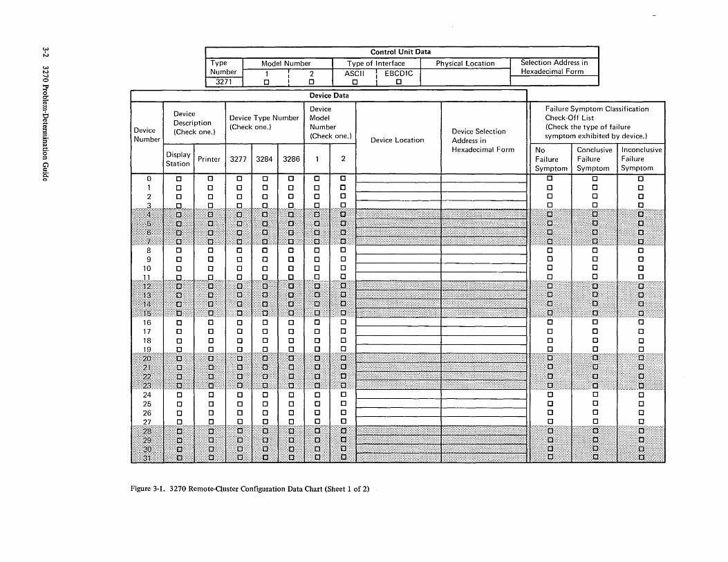
Figure 3-1. 3270 Remote-Ouster Configuration Data Chart (Sheet 1 of 2)
Selection Address in Hexadecimal Form
Failure Symptom Classification Check·Off List (Check the type of failure symptom exhibited by device.)
No Failure Symptom
0 0 0
Conclusive Failure Symptom
0 0 0 0
o o
Inconclusive Failure Symptom
0 0 0 0
o o

:;:d (I)
:3 S. (I)
~ v.>
~ (') o ::s ::n ~ j;! c-. o ::s
If ~
Communication Line Utilization Data
Note: Enter the appropriate data for each I/O configuration on the communication line. Include non-3270 I/O configurations (if any).
Communication Line Identification
Relative Position of Problem Determination Representative I/O Configuration I/O Configuration Type I/O Configuration Location on Communication Line Name Telephone
- Computer Site 1 2 3 4 5 6 7 8 9
10 11 12 13 14 15 16 17 18 19 20 21 22 23 24 25 26 27 28 29 30 31 32
Figure 3-1. 3270 Remote-Cluster Configuration Data Chart (Sheet 2 of 2)

Device exhibits a failure symptom
Phase 1 (Activity to be accomplished by device operator.) r------------ ---- ---- -- --- ----,
~------------~------------~---- ---- -- ~~--------------------------~
Follow the problem-determination procedures specified in Chapter 5 or 6, depending upon the type of device.
Notify supervisor that device exhibits a conclusive failure symptom.
L ___ _
Device that exhibits conclusive failure symptom is defective. Report failure to I BM, and state the device type and model numbers.
No
If the device is a 3277 model 1 or 3277 model 2, use the procedures specified in Chapter 5. If the device is a 3284 model 1, 3284 model 2, 3286 model 1 or 3286 model 2, use the procedures specified in Chapter6.
Notify supervisor that device exhibits an inconclusive failure symptom.
---------1 Phase 2 (Supervisor gathers information from device operators.)
r-- -- -------- - --- ------. I I I Contact the operator of each I I device listed on the I I Configuration Data Chart I
I (Figure 3-1). Record the I failure symptom classification
I information for each I device by placing a check I
I mark in the appropriate square I on the Configuration Data Chart. I I I L_____ ______ I
Sheet 2
Figure 3-2. 3270 Remote-Cluster Configuration Problem-Determination Flow Diagram (Sheet 1 of 5)
3-4 3270 Problem-Determination Guide

Sheet 1
Phase 3 (Supervisor evaluates information obtained from device operators.) r---- -- ------------- --------,
Any device that exhibits a conclusive failure symptom is defective. Report failure to I BM, and state device type and model numbers.
The device that exhibits the inconclusive failure symptom is probably defective. Report failure to I BM, and state the device type and model numbers.
Yes
Yes
L ___________ _
Sheet 3
No
No
No (or not sure)
The 3271 Control Unit is probably defective. Report failure to I BM, and state control unit type and model numbers.
-----------~
Figure 3-2. 3270 Remote-Cluster Configuration Problem-Determination Flow Diagram (Sheet 2 of 5)
Remote-Cluster Configuration 3-5

Sheet 2
1----------------I I I
Yes
Verify that: 1. The 3271 power switch is in the ON position. 2. The 3271 power cable is connected to
power source. 3. Power source circuit breakers are on.
Note: If a discrepancy is observed, it must be rectified (by appropriate personnel) to resolve problem.
Yes
The 3271 Control Unit is probably defective. Report failure to IBM, and state control unit type and model numbers.
Observe all 5 indicators on front of the 3271 Control Unit.
No
Phase 4 (Supervisor performs visual inspection.)
-------1
Observe the STATUS indicator.
Sheet 4
I I I
Figure 3-2. 3270 Remote-Cluster Configuration Problem-Determination Flow Diagram (Sheet 3 of 5)
3-6 3270 Problem-Determination Guide

Sheet 3
Observe the SYSTEM READY and SYNC SEARCH indicators.
Verify that: 1. 3271 interface cable is connected to
appropriate data set.
Yes
2. Data set power cable is connected to power source.
3. Power source circuit breakers are on. 4. All other data-set-related cables and switch
settings (if any) are correct.
Note: If a discrepancy is observed, it must be rectified (by appropriate personnel) to resolve problem.
Yes
Sheet 5
Figure 3-2. 3270 Remote-Ouster Configuration Problem-Determination Flow Diagram (Sheet 4 of 5)
Remote-Cluster Configuration 3-7

Sheet 4
Phase 5 (This phase requires participation by supervisors and computer site personnel.)
r---------------- -I I I
t
Refer to Configuration Data Chart (Figure 3-1) for this information.
No
Failure is probably in communication line facilities or 3270 Display System configuration that exhibits inconclusive failure symptoms. The data set and the 3271 Control Unit are prime suspects.
Yes
No
Failure is probably in computer site equipment, communication line facilities, or 3271 Control Unit.
Failure is probably in communication line facilities or computer site equipment.
Failure is probably in communication line facilities.
Computer site personnel should follow problem - determination procedures, established for the
computer site equipment and/or the communication line facilities, to further isolate failure.
Figure 3-2. 3270 Remote-Cluster Configuration Problem-Determination Flow Diagram (Sheet 5 of 5)
3-8 3270 Problem-Determination Guide
t

To perform the problem-determination procedures described in this chapter, the configuration data chart (Figure 4-1) should contain the current information regarding the status of the 3270 Local-Cluster Configuration.
4.1 CONFIGURATION-RELATED PROCEDURES
The supervisor should follow the procedures described in Figure 4-2.
Chapter 4. 3270 Local-Cluster Configuration
4.2 DEVICE-RELATED PROCEDURES
Device operators should follow the procedures specified in Chapter 5 or 6, depending upon the type of device on which the problem is experienced. Chapter 5 should be used if the device is a 3277 Model 1 or 3277 Model 2 Display Station. Chapter 6 should be used if the device is a 3284 Modell, 3284 Model 2, 3286 Modell, or 3286 Model 2 Printer.
Local-Cluster Configuration 4-1

~
N
W N -...J o ~ o ~ :3 ~ ~ S· Il) g. ::s C) c: s: (II
Device Number
o
Device Description (Check one.)
Type Number
3272
Device Type Number (Check one.)
Model Number
2 o
Device Model Number (Check one.)
~------r-----~r-----~----~-----+----~----~
Display Station
o o o
Printer
o o
3277 I 3284 I 3286
o o
o o
2
Figure 4-1. 3270 Local-Ouster Configuration Data Chart (Sheet 1 of 2)
Control Unit Data
Power Control Option Physical Location
Local Remote o 0
Device Location Control Unit/Device Address in Hexadecimal Form
Failure Symptom Classification Check-Off List (Check the type of failure symptom exhibited by device.)
No I Conclusive I Inconclusive Failure Failure Failure Symptom Symptom Symptom
o 0 0 o 0 0 o 0 0

Channel Utilization Data
Note: Enter the appropriate data for each I/O configuration on the channel. Include non-3270 I/O configurations (if any).
Channel Address
Problem Determination Representative I/O Configuration Description I/O Configuration Location
I Name Telephone -------
Figure 4-1. 3270 Local-Ouster Configuration Data Chart (Sheet 2 of 2)
t"'" 0 0 e. [ (1) ... (') 0 ::s
~ •
... ~ g. ::s
-'=" ~

Device exhibits a failure symptom.
Phase 1 (Activity to be accomplished by device operator.)
1------------------ ---------l
r-------~------..,...._ - - - - - - -r----------------. Follow the problem-determination procedures specified in Chapter 5 or 6, depending upon the type of device.
Notify supervisor that device exhibits a conclusive failure symptom.
L ___ _
Device that exhibits conclusive failure symptom is defective. Report failure to I BM, and state the device type and model numbers.
No
If the device is a 3277 model 1 or 3277 model 2, use the procedures specified in Chapter 5. If the device is a 3284 model 1, 3284 model 2, 3286 model 1, or 3286 model 2, use the procedures specified in Chapter 6.
Notify supervisor that device exhibits an inconclusive failure symptom.
_ ________ J Phase 2 (Supervisor gathers information from device operators.) 1----- ---------l
I I
I I I I
Contact the operator of each device listed on the
Configuration Data Chart (Figure 4-1). Record the
failure sympton classification information for each
device by placing a check mark in the appropiate square on
the Configuration Data Chart.
I I I I I
I I I L _____ _ ________ J
Sheet 2
Figure 4-2. 3270 Local-auster Configuration Problem-Determination Flow Diagram (Sheet 1 of 4)
4-4 3270 Problem-Determination Guide

Sheet 1
Phase 3 (Supervisor evaluates information obtained from device operators.)
r--------------- ----------------1
Any device that exhibits a conclusive failure symptom is defective. Report failure to 18M, and state the device type and model numbers.
The device that exhibits the inconclusive failure symptom is probably defective. Report failure to 18M, and state the device type and model numbers.
Yes
Yes
No
No
No (or not sure)
The 3272 Control Unit is probably defective. Report failure to 18M, and state control unit type and model numbers.
L _____________ _ _ _________ ___ ---1
.------I I I ,
Sheet 3
Observe the 3272 POWER ON indicator.
Phase 4 (This phase requires participation by supervisors and computer room personnel.) -------1
I I I V
No Yes
Sheet 4
Figure 4-2. 3270 Local-Guster Configuration Problem-Determination Flow Diagram (Sheet 2 of 4)
Local-C1uster Configuration 4-5

Activate the control unit POWE R ON switch.
Problem is resolved.
No
Sheet 2
Refer to Configuration Data Chart (Figure 4-1) for this information.
The 3272 Control Unit is probably defective. Report failure to I BM, and state control unit type and model numbers.
Verify that: 1. The 3272 power cable is connected to
power source. 2. Power source circuit breakers are on.
Note: If a discrepancy is observed, it must be rectified (by appropriate personnel) to resolve problem.
Local
No
System remote power control equipment is probably defective.
Figure 4-2. 3270 Local-Cluster Configuration Problem-Determination Flow Diagram (Sheet 3 of 4)
4-6 3270 Problem-Determination Guide

No
The 3272 Control Unit is probably defective. Report failure to I BM, and state control unit type and model numbers.
Sheet 2
Refer to Configuration Data Chart (Figure 4-') for this information.
The computer, channel, or 3272 Control Unit may be the cause of the failure.
The computer, channel, one of the other I/O configurations, or the 3272 Control Unit may be the cause of the failure.
Problem determination procedures established for computer room equipment (computer, channel, etc.) should be utilized to further isolate the failure.
Figure 4-2. 3270 Local-auster Configuration Problem-Determination Flow Diagram (Sheet 4 of 4)
Local-Cluster Configuration 4-7


Chapter 5. 3277 Model 1 and 3277 Model 2 0 isplay Stations
5.1 PROBLEM-DETERMINATION PROCEDURES
When it appears that a failure symptom is exhibited, proceed as follows: 1. Ensure that correct operating procedures have been used
and that the· responses expected are valid functions of a correctly operating configuration. Descriptions of correct operating procedures and expected responses can be verified from the following sources: a. Operator's Guide for IBM 3270 Information Display
Systems. b. The user's guide for the application program being
used. c. Supervisor.
2. After verifying that a failure symptom has been detected (step 1 , above), the failure symptom must be classified as being conclusive or inconclusive. Refer to paragraph 5.2 for a detailed description of failure symptom classification procedures.
3. Notify the supervisor that the display station exhibits a failure symptom, and indicate the failure symptom classification (conclusive or inconclusive).
4. Fill out the Operator Trouble Report form.
5.2 FAILURE SYMPTOM CLASSIFICATION PRO-CEDURES
It is impractical, if not impossible, to list every failure symptom that could be exhibited by the display station. Thus, the method of failure symptom classification used is a process of elimination. A listing of the most likely and most recognizable conclusive failure symptoms is provided in paragraph 5.3. If the display station exhibits one of these failure symptoms, it is classified as conclusive. The failure symptom is classified as inconclusive, however, if it is not contained in the conclusive failure symptom list.
To classify an observed failure symptom, proceed as follows: 1. Develop a mental picture of the failure symptom. 2. Scan the conclusive failure symptom listing (paragraph
5.3) to find a listed failure symptom description that is similar to the observed failure symptom.
Note: The observed failure symptom may contain more conditions than are described in the listed failure symptom. However, it is still possible to classify the observed symptom as conclusive if it satisfies all conditions exactly as described in the listed symptom.
3. Classify the failure symptom. If the observed failure symptom exactly satisfies all the conditions stated in anyone of the listed failure symptom descriptions, it should be classified as conclusive. However, if the observed failure symptom does not satisfy all the conditions stated in anyone of the listed failure symptoms, it should be classified as inconclusive.
The following examples illustrate the failure symptom classification procedure.
Example #1
Ob served Failure Symptom - When a selection is attempted via the selector pen, the detect bars appear and the INPUT INHIBITED indicator comes on, but the designator character does not change.
listed Failure Symptom - The conclusive failure symptom listing (paragraph 5.3) shows that item 2c of paragraph 5.3.3 is satisfied by the observed failure symptom.
Resultant Failure Symptom Classification - The observed failure symptom is classified as conclusive because it satisfies each condition stated by the listed failure symptom description. The state of the INPUT INHIBITED indicator, which is included in the observed failure symptom, is ignored because it is not a specific condition of the listed failure symptom description.
Example #2
Ob served Failure Symptom - When a selection is attempted via the selector pen, the detect bars do not appear and the designator character does not change.
listed Failure Symptom - The conclusive failure symptom listing does not contain a failure symptom description that is completely satisfied by the observed failure symptom.
Resultant Failure Symptom Classification - The observed failure symptom is classified as inconclusive.
5.3 CONCLUSIVE FAILURE SYMPTOM LISTING
5.3.1 Display Malfunctions
1. Empty Screen - The display screen is blank. No visible cursor, characters, or indicators are displayed. The
3277-1 and -2 Display Stations 5-1

INSERT MODE indicator does not come on when the INS MODE key is pressed. Adjustment of the brightness control does not rectify the condition.
Note: This symptom may occur because the display station is not supplied with power. A visual inspection should be made to verify that all of the following conditions are satisfied: a. The display station power control switch is on
(switch pulled out). b. The display station power cable is connected to an
appropriate power source. c. The power source circuit breakers are on.
If any of the above conditions (a through c). are not satisfied, the problem is found, and it can be corrected by satisfying the required conditions. If all of the conditions are satisfied and the symptom persists, it is a conclusive failure symptom.
2. Single Horizontal Line on Screen - The display image consists of a single horizontal line at the top of the display area. The length of the line is equal to the full width of the screen or is equal to approximately two-thirds the width of the screen.
3. Many Horizontal Lines on Screen - The lines are as long as the display area is wide. They may appear in groups or be evenly spaced over a portion or all of the display area. They may appear in lieu of a normal image or be superimposed on a normal image.
4. Screen Full of Squares - A square is displayed in every character position of the display area (i.e., 480 squares for a 3277 Model 1 and 1,920 squares for a 3277 Model 2). The cursor, however, is displayed normally.
5. Brightness Control Is Inoperative 6. Image Is Not Focused 7. Image Size Is Incorrect - The overall dimensions
(vertical and/or horizontal) of the display area are incorrect (too large or too small). The overall dimensions of displayed images are therefore incorrect.
8. Image Position Is Incorrect - The display area is not properly positioned on the display screen. The display area is off-center (shifted left or right and/or shifted up or down) or tilted. Displayed images are therefore off-center or tilted.
9. Inter-Row Spacing Is Incorrect - The vertical spacing between adjacent horizontal rows of character positions, within the display area, is incorrect or uneven.
10. Character Size Is Incorrect 11. Characters Are Distorted - Image contains one or more
characters that are not formed correctly. 12. Characters are displayed normally, but the cursor is not
displayed, and the INPUT INHIBITED indicator remains off.
5-2 3270 Problem-Determination Guide
13. Cursor Position Is Incorrect - The cursor is not positioned the correct vertical distance below a character. It may be drawn through the character area.
14. Cursor Size Is Incorrect - The cursor is t()ol~ng or too short.
15. Multiple cursors are displayed, but the INPUT INHIBITED indicator remains off.
16. Only Indicators Malfunction - One or more of the three indicators (SYSTEM AVAILABLE,' INSERT MODE, and INPUT INHIBITED) malfunction. Except for the malfunctioning indicators, no other failure symptoms are exhibited.
5.3.2 Keyboard Malfunctions
1. Mechanical- One or more keys (or the spacebar) are broken, loose, missing, or bind when operated.
2. CLEAR Key Fails - Pressing the CLEAR key does not erase all characters on the screen, and/or does not position the cursor to character position 0 (top left), and/or does not cause the INPUT INHIBITED indicator to come on.
Note: Some application programs respond to the interrupt generated by the CLEAR key by writing a pattern to the display station. If this is true for the application program that is being used, CLEAR key operation is normal, even if the correct results exist only momentarily.
3. Certain Cursor Control Keys Fail- i.e., Up (t), Down U), Left (+-), Right (~), or Backspace (+-). The cursor does not move properly or the INPUT INHIBITED indicator comes on for one or more of these keys.
4. Typamatic Failures - Typamatic keys function correctly when pressed and released, but one or more do not repeat their function when held fully depressed.
5. Character Key Failures - All keys related to the alphabet, to numerics, to symbols, and to punctuation marks are considered character keys for this discussion.
When attempting to type into an unprotected data field or an unformatted image, one or more of the following malfunctions occur: a. The wrong character enters for one or more character
keys,or b. No character enters for all character keys, and the
INPUT INHIBITED indicator comes on, or c. The correct character enters, but the INPUT
INHIBITED indicator comes on for one or more character keys, or
d. The cursor disappears or does not move properly when a character enters, or
e. No character enters for all character keys, but the cursor advances when each character key is pressed, and the INPUT INHIBITED indicator does not come on.

Note: If it appears that one of these failure symptoms is exhibited, obtain an unformatted image via the CLEAR key (if the application program permits), and verify the symptom by retrying the operation.
6. Program Access Key Failures - The INPUT INHIBITED indicator does not come on for one or more of the following keys: ENTER, PAl, PA2, PA3, TEST REQ, or PFI through PF12.
Note: Refer to item 2, paragraph 5.3.2, for CLEAR key failure symptom.
5.3.3 Selector Pen Malfunctions
1. Mechanical- Selector pen operations cannot be executed error-free, and inspection of the selector pen reveals that: a. Obvious physical damage exists, or
b. The selector pen tip movement, relative to the selector pen barrel, is not smooth when the selector pen switch is activated.
2. Detect Bar or Designator Character Failures: a. Detect bars appear through all selectable fields, even
when selector pen is not being used, or b. Detect bars appear and remain through all selectable
fields when a selection is attempted, or c. Detect bars appear; but the designator character does
not change when a selection is attempted.
5.3.4 Audible Alarm Malfunctions
The audible alarm does not sound when a character is entered from the keyboard into the next-to-Iast character position of the display area (position 478 for a model 1 or position 1918 for a model 2).
3277-1 and -2 Display Stations 5-3


Chapter 6. 3284 Model 1, 3284 Model 2, 3286 Model 1, and 3286 Model 2 Printers
6.1 PROBLEM-DETERMINATION PROCEDURES
When a printer exhibits a failure symptom, proceed as follows: 1. Select the one statement from the three listed below
that best describes the observed failure symptom, and follow the instructions associated with the selected statement: a. The printer is totally inoperative; i.e., printout
operations do not even start. (Skip to step 2.) b. The printer appears to operate correctly except for
the quality of the print density; i.e., the characters are not dark enough. (Skip to step 3.)
c. The printer operates, but its operation is abnormal. The abnormal operation is not limited to the quality of the print density. (Skip to step 4.)
2. When the printer is totally inoperative, make a visual inspection to verify that all of the following conditions are satisfied: a. The PRINT PAT/ON LN/PRINT BFR switch is in the
ON LN position. b. An adequate supply of forms (paper) is properly
loaded. c. The printer top cover is closed. d. The printer power control switch is in the ON
position. e. The printer power cable is connected to an
appropriate power source. f. Power source circuit breakers are on.
If any of the above conditions (a through f) are not satisfied, the problem is found and can be corrected by satisfying the required conditions. If all conditions are satisfied and the printer is still inoperative, skip to step 4.
3. When the printer appears to operate correctly except for the quality of the print density, the problem is probably caused by improper adjustment of the Copy-Control Lever or by a worn ribbon.
If the problem cannot be resolved by adjustment of the Copy-Control Lever or by replacing the ribbon, proceed to step 4.
4. Classify the failure symptom as conclusive or inconclusive. Refer to paragraph 6.2 for detailed failure symptom classification procedures.
6.2 FAILURE SYMPTOM CLASSIFICATION PRO-CEDURES
The classification of printer failure symptoms is simplified by the use of built-in pattern generation facilities. These facilities are controlled by three test switches that are accessible when the printer top cover is open.
To classify a printer failure symptom, proceed as follows: 1. Print the All H test pattern as follows:
a. Place the PRINT PAT/ON LN/PRINT BFR switch in the PRINT PAT position.
b. Place the MODE l/MODE 2 switch in the MODE 2 position.
c. Momentarily operate the START PRINT switch. d. Proceed to step 2.
2. Select the one statement from the three listed below that best describes the results obtained when step 1 was executed, and follow the instructions associated with the selected statement:
Note: Figures 6-1 and 6-2 illustrate the correct All H test patterns. Figure 6-1 applies if the printer is a 3284 Modell or a 3286 Modell; Figure 6-2 applies if the printer is a 3284 Model 2 or a 3286 Model 2.
a. No printout resulted. (Skip to step 5.) b. A correct All H test pattern printout resulted. (Skip
to step 3.) c. An incorrect printout resulted. (Skip to step 5.)
3. Print the Alphameric test pattern as follows: a. Place the PRINT PAT/ON LN/PRINT BFR switch in
the PRINT PAT position. b. Place the MODE l/MODE 2 switch in the MODE 1
position. c. Momentarily operate the START PRINT switch. d. Proceed to step 4.
4. Select the one statement from the three listed below that best describes the results obtained when step 3 was executed, and follow the instructions associated with the selected statement:
Note: Figures 6-3 and 64 illustrate correct Alphameric test patterns. Figure 6-3 applies if the printer is a 3284 Model 1 or a 3286 Modell; Figure 64 applies if the printer is a 3284 Model 2 or a 3286 Model 2.
3284-1 and -2/3286-1 and -2 Printers 6-1

a. No printout resulted. (Skip to step 5.) b. A correct Alphameric test pattern printout resulted.
(Skip to step 6.) c. An incorrect printout resulted. (proceed to step 5.)
5. Classify the failure symptom as conclusive, place the PRINT PAT/ON LN/PRINT BFR switch in the ON LN position, close the printer top cover, and skip to step 7.
6. Classify the failure symptom as inconclusive, place the PRINT PAT/ON LN/PRINT BFR switch in the ON LN position, close the printer top cover, and proceed to step 7.
7. Notify the supervisor that the printer is exhibiting a failure symptom, and indicate the failure symptom classification (conclusive or inconclusive).
8. Complete the Operator Trouble Report form, and attach the printouts that Were obtained from the operational program and/or those that were obtained via the use of the procedures in steps 1 and 3.
6-2 3270 Problem-Determination Guide

HHHHHHHHHHHHHHHHHHHHHHHHHHHHHHHHHHHHHHHHHHHHHHHHHHHHHHHHHHHHHHHHHHHHHHHHHHHHHHHH HHHHHHHHHHHHHHHHHHHHHHHHHHHHHHHHHHHHHHHHHHHHHHHHHHHHHHHHHHHHHHHHHHHHHHHHHHHHHHHH HHHHHHHHHHHHHHHHHHHHHHHHHHHHHHHHHHHHHHHHHHHHHHHHHHHHHHHHHHHHHHHHHHHHHHHHHHHHHHHH HHHHHHHHHHHHHHHHHHHHHHHHHHHHHHHHHHHHHHHHHHHHHHHHHHHHHHHHHHHHHHHHHHHHHHHHHHHHHHHH HHHHHHHHHHHHHHHHHHHHHHHHHHHHHHHHHHHHHHHHHHHHHHHHHHHHHHHHHHHHHHHHHHHHHHHHHHHHHHHH HHHHHHHHHHHHHHHHHHHHHHHHHHHHHHHHHHHHHHHHHHHHHHHHHHHHHHHHHHHHHHHHHHHHHHHHHHHHHHHH HHHHHHHHHHHHHHHHHHHHHHHHHHHHHHHHHHHHHHHHHHHHHHHHHHHHHHHHHHHHHH HHHHHHHHHHHHHHHHHHHHHHHHHHHHHHHHHHHHHHHHHHHHHHHHHHHHHHHHHHHHH
Note: This figure illustrates the contents of the test pattern rather than the size and style of individual characters.
Figure 6-1. 3284 Modell and 3286 Modell All H Test Pattern
HHHHHHHHHHHHHHHHHHHHHHHHHHHHHHHHHHHHHHHHHHHHHHHHHHHHHHHHHHHHHHHHHHHHHHHHHHHHHHHH HHHHHHHHHHHHHHHHHHHHHHHHHHHHHHHHHHHHHHHHHHHHHHHHHHHHHHHHHHHHHHHHHHHHHHHHHHHHHHHH HHHHHHHHHHHHHHHHHHHHHHHHHHHHHHHHHHHHHHHHHHHHHHHHHHHHHHHHHHHHHHHHHHHHHHHHHHHHHHHH HHHHHHHHHHHHHHHHHHHHHHHHHHHHHHHHHHHHHHHHHHHHHHHHHHHHHHHHHHHHHHHHHHHHHHHHHHHHHHHH HHHHHHHHHHHHHHHHHHHHHHHHHHHHHHHHHHHHHHHHHHHHHHHHHHHHHHHHHHHHHHHHHHHHHHHHHHHHHHHH HHHHHHHHHHHHHHHHHHHHHHHHHHHHHHHHHHHHHHHHHHHHHHHHHHHHHHHHHHHHHHHHHHHHHHHHHHHHHHHH HHHHHHHHHHHHHHHHHHHHHHHHHHHHHHHHHHHHHHHHHHHHHHHHHHHHHHHHHHHHHHHHHHHHHHHHHHHHHHHH HHHHHHHHHHHHHHHHHHHHHHHHHHHHHHHHHHHHHHHHHHHHHHHHHHHHHHHHHHHHHHHHHHHHHHHHHHHHHHHH HHHHHHHHHHHHHHHHHHHHHHHHHHHHHHHHHHHHHHHHHHHHHHHHHHHHHHHHHHHHHHHHHHHHHHHHHHHHHHHH HHHHHHHHHHHHHHHHHHHHHHHHHHHHHHHHHHHHHHHHHHHHHHHHHHHHHHHHHHHHHHHHHHHHHHHHHHHHHHHH HHHHHHHHHHHHHHHHHHHHHHHHHHHHHHHHHHHHHHHHHHHHHHHHHHHHHHHHHHHHHHHHHHHHHHHHHHHHHHHH HHHHHHHHHHHHHHHHHHHHHHHHHHHHHHHHHHHHHHHHHHHHHHHHHHHHHHHHHHHHHHHHHHHHHHHHHHHHHHHH HHHHHHHHHHHHHHHHHHHHHHHHHHHHHHHHHHHHHHHHHHHHHHHHHHHHHHHHHHHHHHHHHHHHHHHHHHHHHHHH HHHHHHHHHHHHHHHHHHHHHHHHHHHHHHHHHHHHHHHHHHHHHHHHHHHHHHHHHHHHHHHHHHHHHHHHHHHHHHHH HHHHHHHHHHHHHHHHHHHHHHHHHHHHHHHHHHHHHHHHHHHHHHHHHHHHHHHHHHHHHHHHHHHHHHHHHHHHHHt1H HHHHHHHHHHHHHHHHHHHHHHHHHHHHHHHHHHHHHHHHHHHHHHHHHHHHHHHHHHHHHHHHHHHHHHHHHHHHHHHH HHHHHHHHHHHHHHHHHHHHHHHHHHHHHHHHHHHHHHHHHHHHHHHHHHHHHHHHHHHHHHHHHHHHHHHHHHHHHHHH HHHHHHHHHHHHHHHHHHHHHHHHHHHHHHHHHHHHHHHHHHHHHHHHHHHHHHHHHHHHHHHHHHHHHHHHHHHHHHHH HHHHHHHHHHHHHHHHHHHHHHHHHHHHHHHHHHHHHHHHHHHHHHHHHHHHHHHHHHHHHHHHHHHHHHHHHHHHHHHH HHHHHHHHHHHHHHHHHHHHHHHHHHHHHHHHHHHHHHHHHHHHHHHHHHHHHHHHHHHHHHHHHHHHHHHHHHHHHHHH HHHHHHHHHHHHHHHHHHHHHHHHHHHHHHHHHHHHHHHHHHHHHHHHHHHHHHHHHHHHHHHHHHHHHHHHHHHHHHHH HHHHHHHHHHHHHHHHHHHHHHHHHHHHHHHHHHHHHHHHHHHHHHHHHHHHHHHHHHHHHHHHHHHHHHHHHHHHHHHH HHHHHHHHHHHHHHHHHHHHHHHHHHHHHHHHHHHHHHHHHHHHHHHHHHHHHHHHHHHHHHHHHHHHHHHHHHHHHHHH HHHHHHHHHHHHHHHHHHHHHHHHHHHHHHHHHHHHHHHHHHHHHHHHHHHHHHHHHHHHHHHHHHHHHHHHHHHHHHHH HHHHHHHHHHHHHHHHHHHHHHHHHHHHHHHHHHHHHHHHHHHHHHHHHHHHHHHHHHHHHH HHHHHHHHHHHHHHHHHHHHHHHHHHHHHHHHHHHHHHHHHHHHHHHHHHHHHHHHHHHHHH HHHHHHHHHHHHHHHHHHHHHHHHHHHHHHHHHHHHHHHHHHHHHHHHHHHHHHHHHHHHHH HHHHHHHHHHHHHHHHHHHHHHHHHHHHHHHHHHHHHHHHHHHHHHHHHHHHHHHHHHHHHH HHHHHHHHHHHHHHHHHHHHHHHHHHHHHHHHHHHHHHHHHHHHHHHHHHHHHHHHHHHHHH HHHHHHHHHHHHHHHHHHHHHHHHHHHHHHHHHHHHHHHHHHHHHHHHHHHHHHHHHHHHH
Note: This figure illustrates the contents of the test pattern rather than the size and style of individual characters.
Figure 6-2. 3284 Model 2 and 3286 Model 2 All H Test Pattern
3284-1 and -2/3286-1 and -2 Printers 6-3

B 0 F H ¢ < K M 0 Q ! ~ 5 U W Y % 2 4 6 8 : @ XXCXEFXXI¢X<XXUXJKXMXXPQXX$X)iXX/SXUXXXYXX,X_>XOXX3X56XX9:X@XX" ABCDEFGHI¢.«+U&JKLMNOPQR!$~);~-/STUVWXYZ ,%_>?0123456789:#@'=" ABCDEFGH I¢ • « + I &JKLMNOPQR! $:=) ;..,-/ STUVWXYZ ,%_>? 01234 567 8 9: #@' ="
B 0 F H ¢ < K M 0 Q ! ~ 5 U W Y % 2 4 6 8 : @ XXCXEFXXI¢X<XXIXJKXMXXPQXX$X);XX/SXUXXXYXX,X_>XOXX3X56XX9:X@XX"
X 5 U W Y 5 U W Y
% %
2 4 6 8 @ 2 4 6 8 : @
Notes:
1. A character mayor may not appear in the position marked by the arrow. Disregard any character that may appear.
2. This figure illustrates the contents of the test pattern rather than the size and style of individual characters.
3. The USA ~BCDIC character set is used in this illustration. Pattern will vary, depending on character generator feature installed.
Figure 6-3. 3284 Modell and 3286 Modell Alphameric Test Pattern
'BDFH¢< KMOQ!:: SUWY % 2 .. 68:@ XXCXEFXXI¢X<XXIXJKXMXXPQXX$X)iXX/SXUXXXYXX,X >XOXX3X56XX9:X@XX" ABCDEFGHI¢. «+1 &JKLMNOPQR! $::) i~-/STUVWXYZ ,%=:>?0123456789: #@'=" ABCDEFGH I¢ . «+1 &JKLMNOPQR! $::) i ' -/ STUVWXYZ ,%_>? 0 12 34 56 7 89: #@ '="
B 0 F H ¢ < K M 0 Q ! :: 5 U W Y % 2 4 6 8 : @ XXCXEFXXI¢X<XXIXJKXMXXPQXX$X)iXX/SXUXXXYXX,X_>XOXX3X56XX9:X@XX" ABCDEFGH I¢ . «+1 &JKLMNOPQR! $=:) i~-/ STUVWXYZ ,%_>? 0123456789: #@ '=" ABCDEFGHI¢ .«+U &JKLMNOPQR! $::)i~-/STUVWXYZ ,%_>?0123456789: #@'="
B 0 F H ¢ < K M 0 Q !:: 5 U W Y % 2 4 6 8 : @ XXCXEFXXI¢X<XXIXJKXMXXPQXX$X)iXX/SXUXXXYXX,X_>XOXX3X56XX9:X@XX" ABCDEFGHI¢. «+1 &JKLMNOPQR! $=:) ;~-/STUVWXYZ ,%_>?0123456789: #@'=" ABCDEFGH I¢ . « +1 &JKLMNOPQR! $=:) i~-/ STUVWXYZ ,%_>? 0 12 34 56 7 89: #@ '="
B 0 F H ¢ < K M 0 Q ! =: 5 U W Y % 2 4 6 8 : @ XXCXEFXXI¢X<XXIXJKXMXXPQXX$X)iXX/SXUXXXYXX,X_>XOXX3X56XX9:X@XX" ABCDEFGH I¢ • « +1 &JKLMNOPQR! $=:) i~-/ STUVWXYZ ,%_>? 0 1234 5 6789: #@' =" ABCDEFGH I¢ . «+1 &JKLMNOPQR! $=:) ;-'-/ STUVWXYZ ,%_>? 0 12 34 56 7 89: #@ '="
B 0 F H ¢ < K M 0 Q ! :: 5 U W Y % 2 4 6 8 : @ XXCXEFXXI¢X<XXaXJKXMXXPQXX$X);XX/SXUXXXYXX,X_>XOXX3X56XX9:X@XX" ABCDEFGHI¢ .«+I&JKLMNOPQR! $::);-'-/STUVWXYZ ,%_>?0123456789: #@'=" ABCDEFGHI¢.«+I&JKLMNOPQR!$~)i~-/STUVWXYZ ,%_>?0123456789:#@'="
B 0 F H ¢ < K M 0 Q ! ~ 5 U W Y % 2 4 6 8 : @ XXCXEFXXI¢X<XXIXJKXMXXPQXX$X);XX/SXUXXXYXX,X_>XOXX3X56XX9:X@XX" ABCDEFGHI¢.«+B&JKLMNOPQR!$~);-'-/STUVWXYZ ,%_>?0123456789:#@'=" ABCDEFGHI¢.«+"&JKLMNOPQR!$~)i-'-/STUVWXYZ ,%_>?0123456789:#@'="
X . 5 U W Y % 2 4 5 U W Y % 2 4 5 U W Y % 2 4 5 U W Y % 2 4 5 U W Y % 2 4
Notes: 5 U W Y % 2 4
1. A character mayor may not appear in the position marked by the arrow. Disregard any character that may appear.
2. This figure illustrates the contents of the test pattern rather than the size and style of individual characters.
3. The USA EBCDIC character set is used in this illustration. Pattern will vary, depending on character generator feature installed.
Figure 6-4. 3284 Model 2 and 3286 Model 2 Alphameric Test Pattern
6-4 3270 Problem-Determination Guide
6 8 @ 6 8 @ 6 8 @ 6 8 @ 6 8 @ 6 8 @
B 0 F XXCXEFX ABCDEFG ABCDEFG
B 0 F XXCXEFX
B 0 F XXCXEFX ABCDEFG ABCDEFG
B 0 F XXCXEFX ABCDEFG AB'CDEFG
B 0 F XXCXEFX ABCDEFG ABCDEFG
B 0 F XXCXEFX ABCDEFG ABCDEFG
B 0 F XXCXEFX ABCDEFG ABCDEFG
B 0 F XXCXEFX ABCDEFG ABCDEFG
B 0 F XXCXEFX ABCDEFG ABCDEFG
B 0 F XXCXEFX
B 0 F XXCXEFX ABCDEFG ABCDEFG
B D F XXCXEFX ABCDEFG ABCDEFG
B D F XXCXEFX ABCDEFG ABCDEFG
B D F XXCXEFX ABCDEFG ABCDEFG
B D F XXCXEFX ABCDEFG ABCDEFG
B D F XXCXEFX ABCDEFG ABCDEFG

BT AM (under OS or DOS) provides an online test facility, known as Request-For-Test (or RFT), that may be used to test 3270 devices (display stations and printers). These tests are requested from a display station by the device operator.
The requested tests (subject to the restrictions specified in paragraphs 7.3 and 7.4) may be sent to the display station from which they were requested or to another device (display station or printer).
Online tests are useful problem-determination tools because they provide considerable information concerning system operation. For example, the successful reception of an online test: 1. Verifies that the operating system and the BT AM
application program are executing in the computer. 2. Verifies the continuity of the data-transmission path
from the requesting device to the computer, and from the computer to the device being tested.
3. Verifies that the tested device is capable of executing the functions that are exercised by the given online test.
7.1 ONLINE TESTS RECOMMENDED AS PROBLEM-DETERMINATION TOOLS
The 3270 Basic EBCDIC Test Pattern (Figure 7-1) should be used for: all devices in a 3270 Remote-Standalone Configuration if the 3275 Display Station is equipped with an EBCDIC I/O interface, all devices in a 3270 RemoteCluster Configuration if the 3271 Control Unit is equipped with an EBCDIC I/O interface, and all devices in a 3270 Local-Cluster Configuration.
The 3270 Basic ASCII* Test Pattern (Figure 7-2) should be used for: all devices in a 3270 Remote-Standalone Configuration if the 3275 Display Station is equipped with an ASCII I/O interface, and all devices in a 3270 RemoteCluster Configuration if the 3271 Control Unit is equipped with an ASCII I/O interface.
7.2 TEST CAPABILITIES PROVIDED BY ONLINE TESTS
Twelve online tests are available for testing 3270 devices. The first six (XX=23 through 28) are EBCDIC test patterns that can be used for local and remote devices. The remaining six (XX=29 tluough 34) are ASCII test patterns that can be used only for remote devices. Some of the test
*ASCII, American National Standard Code for Information Interchange, X3.4-1968.
Chapter 7. Online Testing: RFT
patterns are general-purpose; others are mainly intended for use with a specific device type or model.
The testing capabilities of the 12 test patterns are briefly described below:
XX=23 3270 Basic EBCDIC Test Pattern
This test pattern is issued via an Erase/Write command. It checks: 1. All alphameric characters on a display station or printer. 2. The ability of the write control character (WCC) to
sound the audible alarm, start a printer, and specify the 40-character-per-line print format.
3. The ability to create various types of data fields by using certain combinations of: normal intensity, high intensity, nondisplay, selector-pen-detectable, numericonly, protected, and unprotected data.
The Set Buffer Address (SBA) order, the Insert Cursor (I C) order, and the Start Field (SF) order are used.
XX=24 3270 Modell Align EBCDIC Test Pattern
This test pattern is issued via an Erase/Write command. It checks: 1. The position aligriment for a 480-character display
station. 2. The ability of the WCC to sound the audible alarm, start
a printer, and specify the 40-character-per-line print format.
3. The ability to create protected and unprotected data fields. All data fields are normal intenSity.
The Repeat to Address (RA) order, the SBA order, the IC order, and the SF order are used.
XX=25 3270 Model 2 Align EBCDIC Test Pattern
This test pattern is issued via an Erase/Write command. It checks: 1. The position alignment for a 1,920-character display
station. 2. The ability of the WCC to sound the audible alarm, start
a printer, and specify the 80-character-per-line print format.
3. The ability to create protected and unprotected data fields. All data fields are normal intensity.
The RA order, the SBA order, the IC order, and the SF order are used.
XX=26 3270 Orders EBCDIC Test Pattern
This test pattern is issued via an Erase/Write command. It checks:
Online Testing: RFT 7-1

1. The following 3270 orders in EBCDIC: SF, New Line (NL), SBA, IC, RA, Program Tab (PT), Erase Unprotected to Address (EUA), Duplicate (DUP), and Field Mark (FM).
2. The ability of the WCC to sound the audible alarm, start a printer, and specify the 64-character-per-line print format.
3. The ability to create normal intensity and high intensity data fields.
XX=27 3270 EBCDIC Universal Character Set Test Pattern
This test pattern is issued via an Erase/Write command. It checks: 1. The Universal Character Set in EBCDIC at a display
station or printer. 2. The ability of the WCC to sound the audible alann, start
a printer, and specify the 132-character-per-line print format.
3. The NL order and the End of Message (EM) order for a printer.
The SF order and the IC order are also used.
XX=28 3270 NL/EM EBCDIC Test Pattern
This test pattern is issued via an Erase/Write command. It is mainly intended to check the EM order and multiple NL orders on a printer.
The SF order is also used. Nondisplay and nonnal intensity data fields are used.
XX=29-34 3270 ASCII Test Patterns
These six test patterns provide test capabilities that correspond with those provided by the six EBCDIC test patterns (XX=23-28). The transmission of these patterns, however, is in ASCII.
7.3 REQUESTING AN ONLINE TEST FROM A REMOTE 3270 DISPLAY STATION
To initiate an online test, the display station operator should proceed as follows: 1. Position the cursor at the top left (character position 0)
of an unformatted screen. One way to accomplish this is to press the CLEAR key, and then press the RESET key.
2. Enter (via the keyboard) the text of the RFT message in the following fonnat:
XXYYNMMDD
where: xx is a number specifying the desired test (23 through 28 for EBCDIC; 29 through 34 for ASCII).
yy is any number from 01 to 99 (01 is recommended for
7-2 3270 Problem-Detennination Guide
problem determination), depending on the number of test pattern repetitions desired. However, when the test pattern is directed to a printer, a YY value other than 01 is meaningless; the pattern will be sent only once. When directed to a display station, the pattern will be sent YY times.
N is the number 4.
MMDD is a sequence of four alphameric characters specifying the selection addresses of the control unit (M) and the device (D) to which the test is to be sent. All alphabetic characters must be typed in uppercase. To obtain the correct control unit and device characters, refer to the tables presented in Figure 7-3. For example, to send an online test to control unit 20, device 7, in EBCDIC transmission, the operator should type 44GG.
3. Press the TEST REQ key. The INPUT INHIBITED indicator will come on.
If the INPUT INHIBITED indicator stays on, and no online test appears within 30 seconds on the 3270 device that was specified in the MMDD field of the RFT message, proceed as follows: 1. Ensure that each step of the above procedure was
followed, and that the text of the RFT message was entered corr.ectly. If a mistake was made, request the online test again.
Note: All alphabetic characters in the MMDD field must be entered in uppercase. Uppercase entry cannot be verified by observing the 3270 screen, because both lowercase and uppercase inputs are .displayed as uppercase.
2. Check with the system operator to ensure that the operating system and the BT AM application program are still executing in the computer.
3. Check with the system programmer to ensure that the BTAM application program is set up for online test requests. The following requirements must be satisfied: a. OS BT AM application programs must:
(1) Specify EROPT=T in the DCB macro instruction.
(2) Specify a buffer of at least 300 bytes in the READ macro instruction.
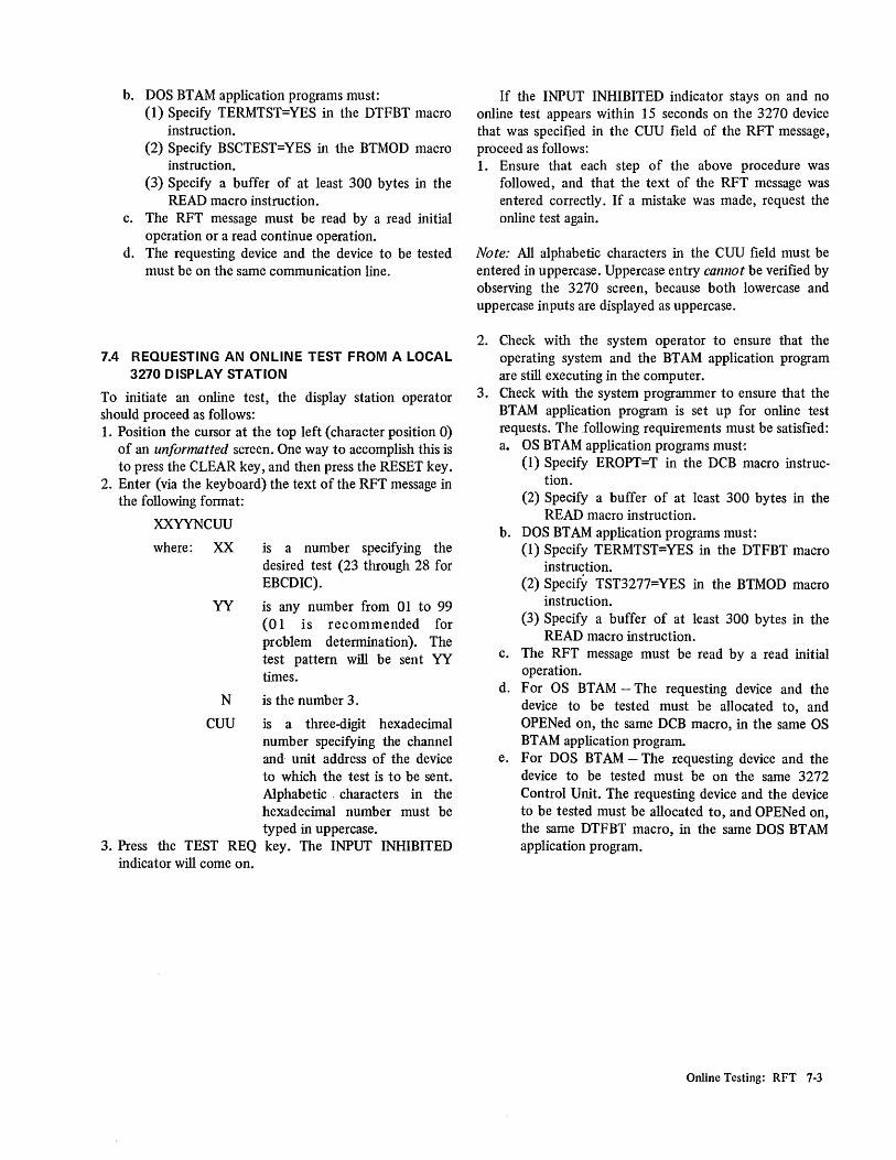
b. DOS BTAM application programs must: (1) Specify TERMTST=YES in the DTFBT macro
instruction. (2) Specify BSCTEST=YES in the BTMOD macro
instruction. (3) Specify a buffer of at least 300 bytes in the
READ macro instruction. c. The RFT message must be read by a read initial
operation or a read continue operation. d. The requesting device and the device to be tested
must be on the same communication line.
7.4 REQUESTING AN ONLINE TEST FROM A LOCAL 3270 DISPLAY STATION
To initiate an online test, the display station operator should proceed as follows: 1. Position the cursor at the top left (character position 0)
of an unformatted screen. One way to accomplish this is to press the CLEAR key, and then press the RESET key.
2. Enter (via the keyboard) the text of the RFT message in the following format:
XXYYNCUU
where: XX is a number specifying the desired test (23 through 28 for EBCDIC).
YY is any number from 01 to 99 (01 is recommended for prcblem determination). The test pattern will be sent YY times.
N is the number 3.
CUU is a three-digit hexadecimal number specifying the channel and unit address of the device to which the test is to be sent. Alphabetic . characters in the hexadecimal number must be typed in uppercase.
3. Press the TEST REQ key. The INPUT INHIBITED indicator will come on.
If the INPUT INHIBITED indicator stays on and no online test appears within 15 seconds on the 3270 device that was specified in the CUU field of the RFT message, proceed as follows: 1. Ensure that each step of the above procedure was
followed, and that the text of the RFT message was entered correctly. If a mistake was made, request the online test again.
Note: All alphabetic characters in the CUU field must be entered in uppercase. Uppercase entry cannot be verified by observing the 3270 screen, because both lowercase and uppercase inputs are displayed as uppercase.
2. Check with the system operator to ensure that the operating system and the BT AM application program are still executing in the computer.
3. Check with the system programmer to ensure that the BT AM application program is set up for online test requests. The following requirements must be satisfied: a. OS BTAM application programs must:
(1) Specify EROPT=T in the DCB macro instruction.
(2) Specify a buffer of at least 300 bytes in the READ macro instruction.
b. DOS BT AM application programs must: (1) Specify TERMTST=YES in the DTFBT macro
instruction. (2) Specify TST3277=YES in the BTMOD macro
instruction. (3) Specify a buffer of at least 300 bytes in the
READ macro instruction. c. The RFT message must be read by a read initial
operation. d. For OS BTAM - The requesting device and the
device to be tested must be allocated to, and OPENed on, the same DCB macro, in the same OS BTAM application program.
e. For DOS BTAM - The requesting device and the device to be tested must be on the same 3272 Control Unit. The requesting device and the device to be tested must be allocated to, and OPENed on, the same DTFBT macro, in the same DOS BT AM application program.
Online Testing: RFT 7-3

Character Position
1
I
Illustration A (See Note.)
I ABCDEFGHIJKLMNOPQRSTUVWXYZ
81 i leopy ABOVE IN TH IS Ll NE INSERT CK 1 1-
161 I I@#$%¢&::C) +! : "<>?-=I; 'I 0123456789, .-A I I -
241 I COpy ABOVE IN THIS LINE I I
321 I ? 5 E L PEN T EST >SEL PEN TEST
I 401--4i-......J1 .L ___ J
Character Position
I
Illustration B (See Note.)
I ABCDEFGHIJKLMNOPQRSTUVWXYZ 81 I /COPY ABOVE IN THIS LINE INSERT
161 I / T @ # $ % ¢ & :: C) +!:" < >? - = I; 'I 0 1 2 3 4 5 6 7 8 241 I /COPY ABOVE-IN THIS LINE
321 I '" ? 5 E L PEN T EST >5 E L PEN T EST 40 1 ---.--1 --'" I I
L ___ ...l
Data Field Definitions
Data Type of Data Field
ABCDEFGHIJKLMNOPQRSTUVWXYZ Protected, Normal Intensity
Protected, Non-Display/Non-Print
COpy ABOVE IN THIS LINE Unprotected, Normal Intensity
INSERT CK Unprotected, Normal Intensity
I@#$%¢&*()_+! :"< >?-=-,;' / Protected, High Intensity, Selector Pen Detectable
0123456789,. - A Protected, Numeric, High Intensity, Selector Pen Detectable
COPY ABOVE IN THIS LINE Unprotected, High Intensity, Selector Pen Detectable
Unprotected, Numeric, High Intensity, Selector Pen Detectable
?SEL PEN TEST Protected, Normal Intensity, Selector Pen Detectable
>SEL PEN TEST Protected, High Intensity, Selector Pen Detectable
Figure 7-1. 3270 Basic EBCDIC Test Pattern (XX=23) (Sheet 1 of 2)
7-4 3270 Problem-Determination Guide

Device - Dependent Variations (See Note.)
Device Test Pattern Description
3275-1 Illustration A applies. W/O 3284-3
3275-1 Illustration A applies, except for the location of the cursor. The cursor jumps to with character position 0, and then moves through succeeding character positions as the 3284-3 3284-3 prints. The cursor comes to rest at character position 0 on the 3275-'
screen at the end of the 3284-3 print operation.
3275-2 Illustration B applies. W/O 3284-3
3275-2 Illustration B applies, except for the location of the cursor. The cursor jumps to with character position 0, and then moves through succeeding character positions as the 3284-3 3284-3 prints. The cursor comes to rest at character position 0 on the 3275-2
screen at the end of the 3284-3 print operation.
3277-' Illustration A applies.
3277-2 Illustration B applies.
3284-' Illustration B applies, except for the cursor. The cursor is not printed. Ignore the 3284-2 character position reference numbers that are provided in the illustration. The
40-characters-per-line print format is specified.
3284-3 Illustration A applies, except for the cursor. The cursor is not printed. Ignore the character position reference numbers that are provided in the illustration. The 40-characters-per-line print format is specified.
3286-' Illustration B applies, except for the cursor. The cursor is not printed. Ignore the 3286-2 character position reference numbers that are provided in the illustration. The
40-characters-per-line print format is specified.
Note: Illustrations A and B result when the USA EBCDIC character generator feature is used. Use the following table to determine the change that occurs when other EBCDIC character generator features are used.
EBCDIC USA UK French German Hex
4A ~ $ ~ 0 5A ! ! ! 0 5B $ £ $ 0 7B # # # A 7C @ @ @ 6 7F " " " A
Figure 7-1. 3270 Basic EBCDIC Test Pattern (XX=23) (Sheet 2 of 2)
Online Testing: RFT 7-5

Character Position
I I
Illustration A (See Note.)
I ABCDEFGHIJKLMNOPQRSTUVWXYZ I
81--+:---- COpy ABOVE IN THIS LINE 1-
INSERT CK
161---+: -----I I@#$%[ &:~ C) _ +] : "<>? - =-'j '/ 0123456789,.-A I
241---1-: -----I COpy ABOVE IN TH IS LINE
321 __ :=-------.JI? S E L PEN T EST >SEL PEN TEST
401 --+: ----I L ____ .J
Character Position
I I
81 I 161 I
I 241 I 321 I
I 401 I L ____ J
Data
Illustration B (See Note.)
ABCDEFGHIJKLMNOPQRSTUVWXYZ ~COPY ABOVE IN THIS LINE INSERT CK ~ I @ # $ % [ & :~ ( ) _ +] : "< >? - = -,; '/ 0 1 2 3 4 5 6 7 8 9 . - A ~COPY ABOVE IN THIS LINE ~?SEL PEN TEST >SEL PEN TEST ~
Data Field Definitions
Type of Data Field
Protected, Normal Intensity
Protected, Non-Display/Non-Print
Unprotected, Normal Intensity
Unprotected, Normal Intensity
Protected, High Intensity, Selector Pen Detectable
Unprotected, High Intensity, Selector Pen Detectable
Unprotected, Numeric, High Intensity, Selector Pen Detectable
Protected, Normal Intensity, Selector Pen Detectable
Pro sity, Sel,ectlJr Pen Det:ect4~ble
Figure 7-2. 3270 Basic ASCII Test Pattern (XX=29) (Sheet 1 of 2)
7,(, 3270 Problem-Determination Guide

Device - Dependent Variations (See Note.)
Device Test Pattern Discription 3275-1 Illustration A applies. W/O 3284-3
3275-1 Illustration A applies, except for the location of the cursor. The cursor jumps to with character position 0, and then moves through succeeding character positions as the 3284-3 3284-3 prints. The cursor comes to rest at character position 0 on the 3275·1
screen at the end of the 3284·3 print operation.
3275·2 Illustration B applies. W/O 3284-3
3275-2 Illustration B applies, except for the location of the cursor. The cursor jumps to with character position 0, and then moves through succeeding character positions as the 3284-3 3284·3 prints. The cursor comes to rest at character position 0 on the 3275-2
screen at the end of the 3284-3 print operation. 3277-1 Illustration A applies.
3277-2 Illustration B applies.
3284-1 Illustration B applies, except for the cursor. The cursor is not printed. Ignore the 3284-2 character position reference numbers that are provided in the illustration. The
40-characters-per·line print format is specified.
3284-3 Illustration A applies, except for the cursor. The cursor is not printed. Ignore the character position reference numbers that are provided in the illustration. The 40-characters-per-line. print format is specified.
3286-1 Illustration B applies, except for the cursor. The cursor is not printed. Ignore the 3286-2 character position reference numbers that are provided in the illustration. The
40-characters-per-line print format is specified.
Note: Illustrations A and B result when the ASCII A character generator feature is used. Use the following table to determine the change that occurs when the ASCII B character generator is used.
ASCII ASCII A ASCII B Hex
21 I !
5E --, A
Figure 7-2. 3270 Basic ASCII Test Pattern (XX=29) (Sheet 2 of 2)
Online Testing: RFT 7·7 .

Control unit addresses for selection. Device addresses for polling, selection, and identification.
Control Address in Address in Address in
Unit Character Hexadecimal Hexadecimal Form Form (EBCDIC) Form (ASCII)
Address in Address in Address in Device Character Hexadecimal Hexadecimal
Form Form (EBCDIC) Form (ASCII)
0 60 2D 0 SP 40 20 1 / 61 2F 1 A C1 41 2 S E2 53 2 B C2 42 3 T E3 54 3 C C3 43 4 U E4 55 4 D C4 44 5 V E5 56 5 E C5 45 6 W E6 57 6 F C6 46 7 X E7 58 7 G C7 47 8 y E8 59 8 H C8 48 9 Z E9 5A 9 I C9 49
10 1(\) 6A 5C 10 ¢ ([) 4A 5B 11 , 6B 2C 11 4B 2E 12 % 6C 25 12 < 4C 3C 13 6D 5F - 13 ( 4D 28 14 > 6E 3E 14 + 4E 2B 15 ? 6F 3F 15 I 4F 21 16 0 FO 30 16 & 50 26 17 1 F1 31 17 J D1 4A 18 2 F2 32 18 K D2 4B 19 3 F3 33 19 L D3 4C
20 4 F4 34 20 M D4 4D 21 5 F5 35 21 N D5 4E 22 6 F6 36 22 0 D6 4F 23 7 F7 37 23 P D7 50 24 8 F8 38 24 0 D8 51 25 9 F9 39 25 R D9 52 26 : 7A 3A 26 ! (] ) 5A 5D 27 # 7B 23 27 $ 5B 24 28 @ 7C 40 28 * 5C 2A 29 , 7D 27 29 ) 5D 29
30 = 7E 3D 30 , 5E 3B 31 II '7F 22 31 ...., 5F 5E
General Poll II 7F 22
Figure 7-3. Selection Address Conversion Tables
7-8 3270 Problem-Determination Guide

The index, presented below, lists the major topics presented in this manual. The index is intended to be used as a quick reference to those major topics. When it appears that a problem exists in a device or a configuration, use the chapter (2, 3, or 4) designated in the Contents for the I/O configuration in which the problem is experienced. Do not use this index to fmd specific corrective actions when an apparent problem exists.
All H Test Pattern: 3284 Modell and 3286 Modell 6-3 (Fig. 6-1) 3284 Model 2 and 3286 Model 2 6-3 (Fig. 6-2) 3284 Model 3 2-11 (Fig. 2-3)
Alphameric Test Pattern: 3284 Modell and 3286 Modell 6-4 (Fig. 6-3) 3284 Model 2 and 3286 Model 2 6-4 (Fig. 6-4) 3284 Model 3 2-11 (Fig. 2-4)
Assumptions 1-1
Basic ASCII Test Pattern 7-6 (Fig. 7-2) Basic EBCDIC Test Pattern 7-1, 7-4 (Fig. 7-1)
Conclusive Failure Symptoms (Defmed) 1-2 ConfIguration Data Chart:
Deimed 1-1 Local-Cluster Configuration 4-2 (Fig. 4-1) Remote-Cluster ConfIguration 3-2 (Fig. 3-1) Remote-Standalone ConfIguration 2-4 (Fig. 2-1)
ConiIgUrations 1-1 Control Unit Addresses 7-8 (Fig. 7-3) Conversion Tables, Selection Address 7-8 (Fig. 7-3)
Deimitions 1-1 Device Addresses 7-8 (Fig. 7-3) Device Operator (Defined) 1-2
Failure Symptom ClassifIcation: 3275 Models 1 and 2 2-1 3277 Models 1 and 2 5-1 3284 Model 3 2-3 3284 Models 1 and 2 6-1 3286 Models 1 and 2 6-1
Failure Symptoms (Defmed) 1-2 Flow Diagrams (Problem Determination):
Local-Cluster ConfIguration 4-4 (Fig. 4-2) Remote-Cluster ConfIguration 3-4 (Fig. 3-2) Remote-Standalone ConfIguration 2-6 (Fig. 2-2)
Inconclusive Failure Symptoms 1-2 I/O ConfIguration (Defmed) 1-1
Local-Cluster ConfIgUration: ConfIguration Data Chart 4-2 (Fig. 4-1) Defmed 1-1 Problem-Determination Flow Diagram 4-4 (Fig. 4-2)
Online Testing (RFT) 7-1 Online Tests:
Capabilities 7-1 Recommended as Problem-Determination Tools 7-1 Requesting from a Local Display Station 7-3 Requesting from a Remote Display Station 7-2
Personnel Designations 1-2 Problem-Determination Flow Diagrams (Defined) 1-2 Problem-Determination Procedures:
Local-Cluster ConfIguration 4-1 Remote-Cluster Configuration 3-1 Remote-Standalone ConfIguration 2-1
Purpose (of manual) 1-1
Recommended Practices 1-2 Remote-Cluster ConfIgUration:
ConfIguration Data Chart 3-2 (Fig. 3-1) Defmed 1-1 Problem-Determination Flow Diagram 3-4 (Fig. 3-2)
Remote-Standalone ConfIguration: ConfIguration Data Chart 2-4 (Fig. 2-1) Defmed 1-1 Problem-Determination Flow Diagram 2-6 (Fig. 2-2)
Request for Test (RFn 7-1 Requesting Online Tests:
From Local Display Station 7-3 From Remote Display Station 7-2
Selection Address Conversion Tables 7-8 (Fig. 7-3) Supervisor 1-2
Test Patterns: AllH:
3284 Modell and 3286 Modell 6-3 (Fig. 6-1) 3284 Model 2 and 3286 Model 2 6-3 (Fig. 6-2) 3284 Model 3 2-11 (Fig. 2-3)
Alphameric: 3284 Modell and 3286 Modell 6-4 (Fig. 6-3) 3284 Model 2 and 3286 Model 2 6-4 (Fig. 6-4) 3284 Model 3 2-11 (Fig. 2-4)
Basic ASCII 7-6 (Fig. 7-2) Basic EBCDIC 7-1, 7-4 (Fig. 7-1) Provided by Online Tests 7-1
Index
X-I


o c ... o ., '11 o c: » 0' :J ca r S' CD
3270 Information Display System Problem Determination Guide
Order No. GA27·2750·0
Your views about this publication may help improve its usefulness,' this form will be sent to the author ~ department for appropriate action. Using this form to request system assistance or additional publications will delay response, however. For more direct handling of such request, please contact your IBM representative or the IBM Branch Office serving your locality.
Possible topics for comment are:
Clarity Accuracy Completeness Organization Index Figures Examples Legibility
READER'S COMMENT FORM
What is your occupation? _____________________________ _
Number of latest Technical Newsletter (if any) concerning this publication: ____________ _
Please indicate if you wish a reply. DYes o No
If yes: Name
Address
Thank you for your cooperation. No postage stamp necessary if mailed in the U.S.A. (Elsewhere, an IBM office or representative will be happy to forward your comments.)

GA27·2750·0
Your comments, please ...
Your comments, together with your answer to the questions on the back of this form will help us produce better publications for your use. Your comments will be carefully reviewed by the persons responsible for writing and publishing this material. All comments and suggestions become the property of IBM.
Fold
Fold
Business Reply Mail No postage stamp necessary if mailed in the U.S.A.
Postage will be paid by:
I nternational Business Machines Corporation Department 520 Neighborhood Road Kingston, New York 12401
International Business Machines Corporation Data Processing Division 1133 Westchester Avenue, White Plains, New York 10604 (U.S.A. only)
IBM World Trade Corporation 821 United Nations Plaza, New York, New York 10017 (International)
Fold
Fold
First Class Permit 40 Armonk New York
(") c: ... Q "T1 o 0: l> 0' ::s
10
r 3' (1)


GA27-2750-0
~rnlli! .!I
International Business Machines Corporation Data Processing Division 1133 Westchester Avenue, White Plains, New York 10604 (U.S.A. only)
IBM World Trade Corporation 821 United Nations Plaza, New York, New York 10017 (International)
c....: I\.: ...... C ""t ~ o 2: CD
3 u CD .-+ CD
3 :;' Q) .-+ 0' :::l G) C [i CD
G)
» N -....J ~ -....J (J'1 o o


