Devil physics The baddest class on campus IB Physics Pre-IB Physics
IB PHYSICS OPTION: ENGINEERING PHYSICS
• Atit Bhargava •
All rights reserved. No part of this publication may be reproduced, stored in a retrieval system, or transmitted in any form or by any means, electronic, mechanical, photocopying, recording or otherwise, without the prior permission of Science Press. ABN 98 000 073 861
© Science Press 2016First published 2016
Science PressPrivate Bag 7023 Marrickville NSW 1475 AustraliaTel: +61 2 9516 1122 Fax: +61 2 9550 [email protected] www.sciencepress.com.au
Contents
Words to Watch iv
Introduction v
Dot Points
Rigid Bodies and Rotational Dynamics vi
Thermodynamics vi
Fluids and Fluid Dynamics vi
Forced Vibrations and Resonance vi
Questions
Rigid Bodies and Rotational Dynamics 1
Thermodynamics 15
Fluids and Fluid Dynamics 29
Forced Vibrations and Resonance 43
Answers
Rigid Bodies and Rotational Dynamics 50
Thermodynamics 55
Fluids and Fluid Dynamics 61
Forced Vibrations and Resonance 66
Appendices
Data Sheet 68
Periodic Table 69
iii Contents
Science Press
Dot Point IB Physics Option: Engineering Physics
account, account for State reasons for, report on,
give an account of, narrate a series of events or
transactions.
analyse Interpret data to reach conclusions.
annotate Add brief notes to a diagram or graph.
apply Put to use in a particular situation.
assess Make a judgement about the value of
something.
calculate Find a numerical answer.
clarify Make clear or plain.
classify Arrange into classes, groups or categories.
comment Give a judgement based on a given
statement or result of a calculation.
compare Estimate, measure or note how things are
similar or different.
construct Represent or develop in graphical form.
contrast Show how things are different or opposite.
create Originate or bring into existence.
deduce Reach a conclusion from given information.
define Give the precise meaning of a word, phrase or
physical quantity.
demonstrate Show by example.
derive Manipulate a mathematical relationship(s) to
give a new equation or relationship.
describe Give a detailed account.
design Produce a plan, simulation or model.
determine Find the only possible answer.
discuss Talk or write about a topic, taking into account
different issues or ideas.
distinguish Give differences between two or more
different items.
draw Represent by means of pencil lines.
estimate Find an approximate value for an unknown
quantity.
evaluate Assess the implications and limitations.
examine Inquire into.
explain Make something clear or easy to understand.
extract Choose relevant and/or appropriate details.
extrapolate Infer from what is known.
hypothesise Suggest an explanation for a group of facts or phenomena.
identify Recognise and name.
interpret Draw meaning from.
investigate Plan, inquire into and draw conclusions about.
justify Support an argument or conclusion.
label Add labels to a diagram.
list Give a sequence of names or other brief answers.
measure Find a value for a quantity.
outline Give a brief account or summary.
plan Use strategies to develop a series of steps or processes.
predict Give an expected result.
propose Put forward a plan or suggestion for consideration or action.
recall Present remembered ideas, facts or experiences.
relate Tell or report about happenings, events or circumstances.
represent Use words, images or symbols to convey meaning.
select Choose in preference to another or others.
sequence Arrange in order.
show Give the steps in a calculation or derivation.
sketch Make a quick, rough drawing of something.
solve Work out the answer to a problem.
state Give a specific name, value or other brief answer.
suggest Put forward an idea for consideration.
summarise Give a brief statement of the main points.
synthesise Combine various elements to make a whole.
Words to Watch
Dot Point IB Physics Option: Engineering Physicsiv
Science Press
Words to Watch
What the book includes
This book provides questions and answers for each dot point in the IB Physics Option: Engineering Physics syllabus from the International Baccalaureate Diploma Programme for Physics:
• Rigid Bodies and Rotational Dynamics
• Thermodynamics
• Fluids and Fluid Dynamics
• Forced Vibrations and Resonance
Format of the book
The book has been formatted in the following way:
1.1 Subtopic from syllabus.
1.1.1 Assessment statement from syllabus.
1.1.1.1 First question for this assessment statement.
1.1.1.2 Second question for this assessment statement.
The number of lines provided for each answer gives an indication of how many marks the question might be worth in an examination. As a rough rule, every two lines of answer might be worth 1 mark.
How to use the book
Completing all questions will provide you with a summary of all the work you need to know from the syllabus. You may have done work in addition to this with your teacher as extension work. Obviously this is not covered, but you may need to know this additional work for your school exams.
When working through the questions, write the answers you have to look up in a different colour to those you know without having to research the work. This will provide you with a quick reference for work needing further revision.
Introduction
v
Science Press
Dot Point IB Physics Option: Engineering Physics Introduction
Verbs to Watch
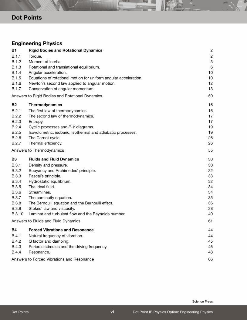
Engineering PhysicsB1 Rigid Bodies and Rotational Dynamics 2
B.1.1 Torque. 2B.1.2 Moment of inertia. 3B.1.3 Rotational and translational equilibrium. 6B.1.4 Angular acceleration. 10B.1.5 Equations of rotational motion for uniform angular acceleration. 10B.1.6 Newton’s second law applied to angular motion. 12B.1.7 Conservation of angular momentum. 13
Answers to Rigid Bodies and Rotational Dynamics. 50
B2 Thermodynamics 16
B.2.1 The first law of thermodynamics. 16B.2.2 The second law of thermodynamics. 17B.2.3 Entropy. 17B.2.4 Cyclic processes and P-V diagrams. 19B.2.5 Isovolumetric, isobaric, isothermal and adiabatic processes. 19B.2.6 The Carnot cycle. 26B.2.7 Thermal efficiency. 26
Answers to Thermodynamics 55
B3 Fluids and Fluid Dynamics 30
B.3.1 Density and pressure. 30B.3.2 Buoyancy and Archimedes’ principle. 32B.3.3 Pascal’s principle. 33B.3.4 Hydrostatic equilibrium. 32B.3.5 The ideal fluid. 34B.3.6 Streamlines. 34B.3.7 The continuity equation. 35B.3.8 The Bernoulli equation and the Bernoulli effect. 36B.3.9 Stokes’ law and viscosity. 38B.3.10 Laminar and turbulent flow and the Reynolds number. 40
Answers to Fluids and Fluid Dynamics 61
B4 Forced Vibrations and Resonance 44
B.4.1 Natural frequency of vibration. 44B.4.2 Q factor and damping. 45B.4.3 Periodic stimulus and the driving frequency. 45B.4.4 Resonance. 48
Answers to Forced Vibrations and Resonance 66
Dot Points
Dot Point IB Physics Option: Engineering Physicsvi
Science Press
Dot Points

DOT POINT
Rigid Bodies and Rotational Dynamics
B1
1 Rigid Bodies and Rotational Dynamics
Science Press
Dot Point IB Physics Option: Engineering Physics

B1 Rigid Bodies and Rotational Dynamics.
B.1.1 Torque.
B.1.1.1 What is torque? ������������������������������������������������������������������������������������������������������������������������������������������������������������������������������������������������
B.1.1.2 How is the action of a torque different from that of a force? �������������������������������������������������������������������������������������������������
���������������������������������������������������������������������������������������������������������������������������������������������������������������������������������������������������������������������������������������������������������������
B.1.1.3 Recall the mathematical expression for torque of a body in terms of force, F applied a distance d from a pivot point.
���������������������������������������������������������������������������������������������������������������������������������������������������������������������������������������������������������������������������������������������������������������
B.1.1.4 List three factors which affect the magnitude of torque about a pivot point. ��������������������������������������������������������������
���������������������������������������������������������������������������������������������������������������������������������������������������������������������������������������������������������������������������������������������������������������
B.1.1.5 The figures below illustrate forces acting on a beam. The beam is 0.8 m long.
In each case, calculate the torque around the point marked X.
20 N
10 N
10 N
10 N
10 N
10 N
0 0.4 m 0.5 m 0.8 mLength
(a)
(c)
(e)
(b)
(d)
(f)50º
B.1.1.6 The maximum torque a force of 10 N can exert on a beam 6 m long is:
(A) 30 N m (B) 60 N m (C) 16 N m (D) 360 N m
B.1.1.7 A force of 10 N is applied at the centre of mass of a beam 6 m long. What is the maximum torque it can exert?
(A) 30 N m (B) 16 N m (C) 60 N m (D) 15 N m
B.1.1.8 The beam shown holds two objects of masses 70 kg and 30 kg, and tries to balance at the fulcrum. Examine the structure which is not in equilibrium then answer the questions that follow.
(a) What is the magnitude and direction of the torque exerted by the 70 kg mass on the fulcrum?
����������������������������������������������������������������������������������������������������������������������������������������������������
(b) What is the magnitude and direction of the torque exerted by the 30 kg mass on the fulcrum?
���������������������������������������������������������������������������������������������������������������������������������������������������������������������������������������������������������������������������������������������������������������
Answers
Torque (N m)
(a)
(b)
(c)
(d)
(e)
(f)
70 kg30 kg
BA
4 m2 m
2Rigid Bodies and Rotational Dynamics
Science Press
Dot Point IB Physics Option: Engineering Physics

(c) The beam will: (A) Eventually become horizontal and in equilibrium.
(B) Move downwards at B.
(C) Move downwards at A.
(D) Break at the fulcrum.
B.1.1.9 A ladder of length L and mass m leans against a wall making an angle θ with the floor. As the angle θ is decreased, the ladder begins to get destabilised and eventually reaches a value θc where it begins to irretrievably slide away from the wall.
Consider the torques around the point of contact between the ladder and the wall, marked X.
(a) On the figure show the location and direction of:
(i) The gravitational force on the ladder Fg.
(ii) The normal reaction force from the wall, Nw.
(iii) The reaction force from the ground Ng.
(iv) The force of friction between the ladder and the ground Flg.
(v) The force of friction between the ladder and the wall Flw.
(b) What is the torque exerted by the following forces, in each case around the point X?
(i) Fg ��������������������������������������������������������������������������������������������������������������������������������������������������������������������������������������������������������������������
(ii) Nw ������������������������������������������������������������������������������������������������������������������������������������������������������������������������������������������������������������������
(iii) Ng �������������������������������������������������������������������������������������������������������������������������������������������������������������������������������������������������������������������
(c) Which of the following statements (one or more) are true when θ ≤ θc? (A) The horizontal component of Ng > Flg.
(B) The Flg > the horizontal component of Ng.
(C) The normal reaction force from the wall becomes very low.
(D) The weight of the ladder moves away from the centre of mass of the ladder.
B.1.2 Moment of inertia.
B.1.2.1 What is ‘moment of inertia’? ���������������������������������������������������������������������������������������������������������������������������������������������������������������������
B.1.2.2 What three main factors does the moment of inertia depend on? �������������������������������������������������������������������������������������
���������������������������������������������������������������������������������������������������������������������������������������������������������������������������������������������������������������������������������������������������������������
B.1.2.3 The linear analog for the moment of inertia is:
(A) Energy
(B) Weight
(C) Mass
(D) Momentum
B.1.2.4 What is the mathematical expression for the moment of inertia of a point mass about a rotation axis?
���������������������������������������������������������������������������������������������������������������������������������������������������������������������������������������������������������������������������������������������������������������
B.1.2.5 How is the moment of inertia of one particle used in determining the moment of inertia of a rigid body?
���������������������������������������������������������������������������������������������������������������������������������������������������������������������������������������������������������������������������������������������������������������
���������������������������������������������������������������������������������������������������������������������������������������������������������������������������������������������������������������������������������������������������������������
X
θ
3 Rigid Bodies and Rotational Dynamics
Science Press
Dot Point IB Physics Option: Engineering Physics
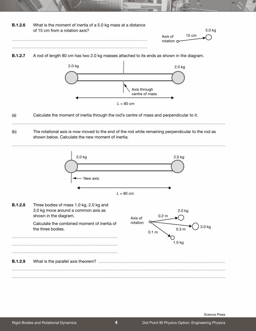
B.1.2.6 What is the moment of inertia of a 5.0 kg mass at a distance of 15 cm from a rotation axis?
������������������������������������������������������������������������������������������������������������������������������������������������������������������
������������������������������������������������������������������������������������������������������������������������������������������������������������������
B.1.2.7 A rod of length 80 cm has two 2.0 kg masses attached to its ends as shown in the diagram.
L = 80 cm
Axis throughcentre of mass
2.0 kg 2.0 kg
(a) Calculate the moment of inertia through the rod’s centre of mass and perpendicular to it.
���������������������������������������������������������������������������������������������������������������������������������������������������������������������������������������������������������������������������������������������������������������
(b) The rotational axis is now moved to the end of the rod while remaining perpendicular to the rod as shown below. Calculate the new moment of inertia.
���������������������������������������������������������������������������������������������������������������������������������������������������������������������������������������������������������������������������������������������������������������
L = 80 cm
New axis
2.0 kg 2.0 kg
B.1.2.8 Three bodies of mass 1.0 kg, 2.0 kg and 3.0 kg move around a common axis as shown in the diagram.
Calculate the combined moment of inertia of the three bodies.
������������������������������������������������������������������������������������������������������������������������������
������������������������������������������������������������������������������������������������������������������������������
������������������������������������������������������������������������������������������������������������������������������
B.1.2.9 What is the parallel axis theorem? ��������������������������������������������������������������������������������������������������������������������������������������������������������
���������������������������������������������������������������������������������������������������������������������������������������������������������������������������������������������������������������������������������������������������������������
���������������������������������������������������������������������������������������������������������������������������������������������������������������������������������������������������������������������������������������������������������������
Axis ofrotation
5.0 kg15 cm
Axis ofrotation
2.0 kg
3.0 kg
1.0 kg
0.2 m
0.3 m 0.1 m
4Rigid Bodies and Rotational Dynamics
Science Press
Dot Point IB Physics Option: Engineering Physics
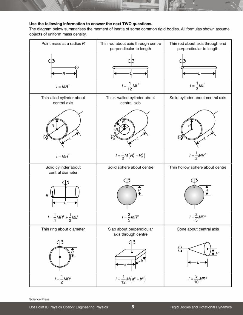
Use the following information to answer the next TWO questions. The diagram below summarises the moment of inertia of some common rigid bodies. All formulas shown assume objects of uniform mass density.
Point mass at a radius R Thin rod about axis through centre perpendicular to length
Thin rod about axis through end perpendicular to length
R L L
I MR=2 I ML=
112
2
I ML=13
2
Thin-alled cylinder about central axis
Thick-walled cylinder about central axis
Solid cylinder about central axis
L
R
L
R2
R1
L
R
I MR=2 I M R R= +( )1
2 12
22 I MR=
12
2
Solid cylinder about central diameter
Solid sphere about centre Thin hollow sphere about centre
L
R
R R
I MR ML= +14
12
2 2 I MR=25
2 I MR=23
2
Thin ring about diameter Slab about perpendicular axis through centre
Cone about central axis
R
ab L
R
I MR=12
2 I M a b= +( )112
2 2 I MR=3
102
5 Rigid Bodies and Rotational Dynamics
Science Press
Dot Point IB Physics Option: Engineering Physics
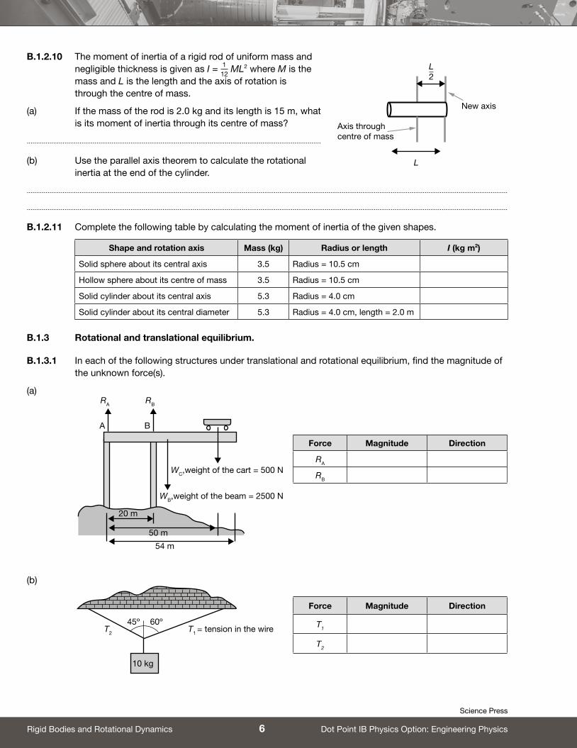
B.1.2.10 The moment of inertia of a rigid rod of uniform mass and negligible thickness is given as I = 1
12 ML2 where M is the
mass and L is the length and the axis of rotation is through the centre of mass.
(a) If the mass of the rod is 2.0 kg and its length is 15 m, what is its moment of inertia through its centre of mass?
������������������������������������������������������������������������������������������������������������������������������������������������������������
(b) Use the parallel axis theorem to calculate the rotational inertia at the end of the cylinder.
���������������������������������������������������������������������������������������������������������������������������������������������������������������������������������������������������������������������������������������������������������������
���������������������������������������������������������������������������������������������������������������������������������������������������������������������������������������������������������������������������������������������������������������
B.1.2.11 Complete the following table by calculating the moment of inertia of the given shapes.
Shape and rotation axis Mass (kg) Radius or length I (kg m2)
Solid sphere about its central axis 3.5 Radius = 10.5 cm
Hollow sphere about its centre of mass 3.5 Radius = 10.5 cm
Solid cylinder about its central axis 5.3 Radius = 4.0 cm
Solid cylinder about its central diameter 5.3 Radius = 4.0 cm, length = 2.0 m
B.1.3 Rotational and translational equilibrium.
B.1.3.1 In each of the following structures under translational and rotational equilibrium, find the magnitude of the unknown force(s).
(a)
(b)
L
L_2
Axis throughcentre of mass
New axis
B
RB
A
RA
WC,weight of the cart = 500 N
WB,weight of the beam = 2500 N
20 m
50 m
54 m
Force Magnitude Direction
RA
RB
10 kg
60º45ºT1 = tension in the wireT2
Force Magnitude Direction
T1
T2
6Rigid Bodies and Rotational Dynamics
Science Press
Dot Point IB Physics Option: Engineering Physics

(c)
(d)
B.1.3.2 An object of mass 15 kg is positioned on a plank as shown in the diagram.
2 m x m
(a) How far from the fulcrum (centre of mass), x, should the second object of mass 30 kg be placed so that the plank stays horizontal in perfect balance?
���������������������������������������������������������������������������������������������������������������������������������������������������������������������������������������������������������������������������������������������������������������
(b) What would be the magnitude of the reaction force at the fulcrum in this balanced position? You may take the reaction force to be perpendicular to the beam when in perfect horizontal balance.
���������������������������������������������������������������������������������������������������������������������������������������������������������������������������������������������������������������������������������������������������������������
B.1.3.3 A cart of mass 1000 kg stands on a bridge on a nodal point as shown in the figure.
(a) What must be the nature (compression or tension) and magnitude of the forces in the members AB and BC that are at an angle of 60° from the platform beams?
������������������������������������������������������������������������������������������������������������������������������������������������������
������������������������������������������������������������������������������������������������������������������������������������������������������
(b) What type of forces (compression or tension) are in the arms CD and AE?
���������������������������������������������������������������������������������������������������������������������������������������������������������������������������������������������������������������������������������������������������������������
10 kg
30º
T1T2
Force Magnitude Direction
T1
T2
W 30o
T1 = tension force in the tie
Fw= reactionforce from
the wall
0.5 m
1.5 m
Weight of beam = 300 N
1.0 m
Load = 100 N
Force Magnitude Direction
T1 Shown in figure
Fw
E
A
D
C
B
7 Rigid Bodies and Rotational Dynamics
Science Press
Dot Point IB Physics Option: Engineering Physics
DOT POINT
Answers
49 Answers
Science Press
Dot Point IB Physics Option: Engineering Physics
Rigid Bodies and Rotational Dynamics
B.1.1.1 Torque is the ability of a force to cause rotation of an object about an axis or a pivot.
B.1.1.2 A force causes a push or a pull while a torque causes rotation of an object.
B.1.1.3 Torque, τ = F × d. It is measured in N m.
B.1.1.4 The magnitude of the applied force, the angle at which the applied force is applied to the body and the distance of the point of application to the pivot point.
B.1.1.5 τ = F × d┴ = Fd sin θ in each of the following cases. Clockwise torque is negative and anticlockwise is positive.
(a) τ = –10 × 0.8 = –8 N m
(b) τ = –10 × 0.1 = –1 N m
(c) 0
(d) τ = +10 × 0.4 = +4 N m
(e) The component of F that does useful work is F sin θ : The other component F cos θ exerts a pull away from hinge. τ = –(10 sin 50°) × 0.8 = –6.1 N m
(f) τ = –20 × 0.8 = –16 N m
B.1.1.6 B The maximum torque will be when the force applied is perpendicular to the beam at the farthest end = 10 × 6 = 60 N.
B.1.1.7 A The force is perpendicular to the beam and the distance is half the length. Therefore torque = 10 × 3 = 30 N m.
B.1.1.8 (a) The torque by the 70 kg mass is anticlockwise, hence given a positive sign and = 70 × 2 = 140 N m.
(b) The torque by the 30 kg mass is clockwise, hence given a negative sign and = –30 × 4 = –120 N m.
(c) The beam will move down at A, hence correct option is (C).
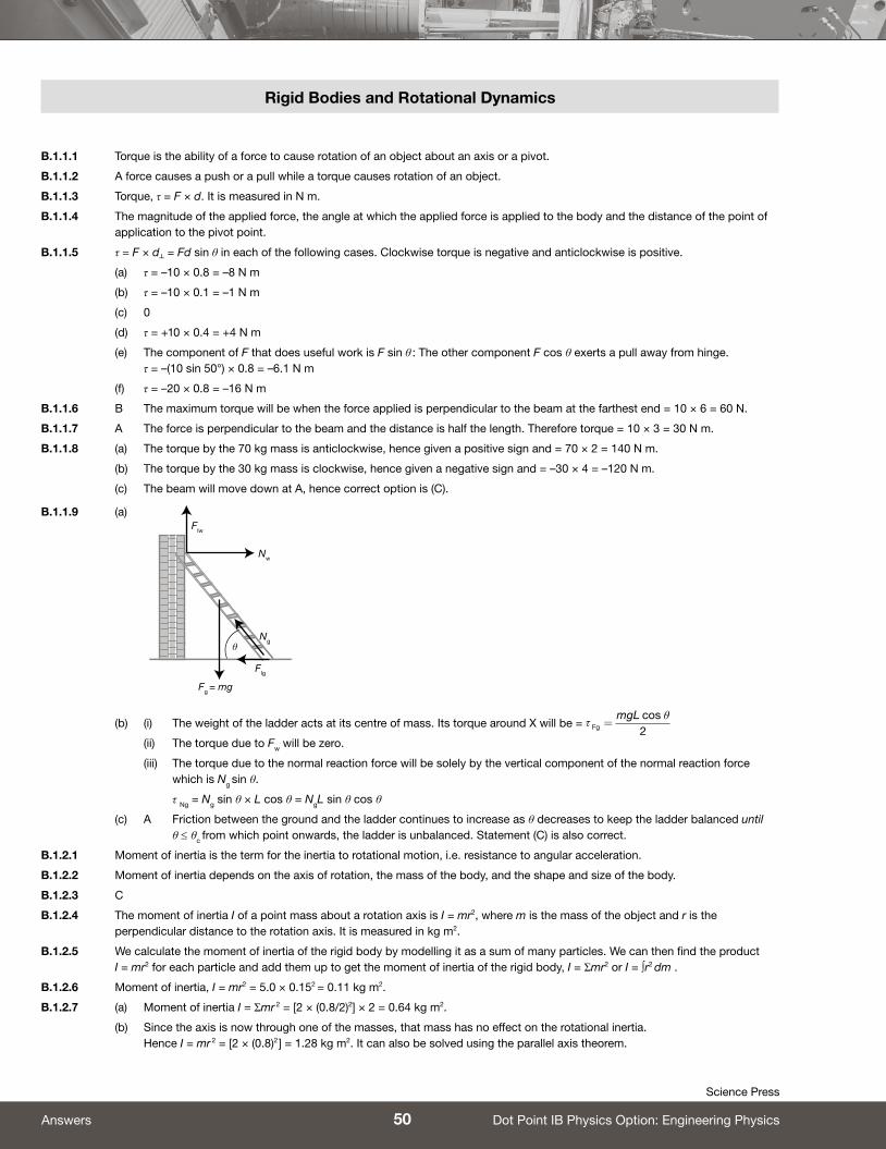
B.1.1.9 (a)
(b) (i) The weight of the ladder acts at its centre of mass. Its torque around X will be = τθ
Fg
mgL=
cos2
(ii) The torque due to Fw will be zero.
(iii) The torque due to the normal reaction force will be solely by the vertical component of the normal reaction force which is Ng sin θ.
τ Ng = Ng sin θ × L cos θ = NgL sin θ cos θ
(c) A Friction between the ground and the ladder continues to increase as θ decreases to keep the ladder balanced until θ ≤ θc from which point onwards, the ladder is unbalanced. Statement (C) is also correct.
B.1.2.1 Moment of inertia is the term for the inertia to rotational motion, i.e. resistance to angular acceleration.
B.1.2.2 Moment of inertia depends on the axis of rotation, the mass of the body, and the shape and size of the body.
B.1.2.3 C
B.1.2.4 The moment of inertia I of a point mass about a rotation axis is I = mr2, where m is the mass of the object and r is the perpendicular distance to the rotation axis. It is measured in kg m2.
B.1.2.5 We calculate the moment of inertia of the rigid body by modelling it as a sum of many particles. We can then find the product I = mr2 for each particle and add them up to get the moment of inertia of the rigid body, I = Σmr2 or I = ∫r2 dm .
B.1.2.6 Moment of inertia, I = mr2 = 5.0 × 0.152 = 0.11 kg m2.
B.1.2.7 (a) Moment of inertia I = Σmr 2 = [2 × (0.8/2)2] × 2 = 0.64 kg m2.
(b) Since the axis is now through one of the masses, that mass has no effect on the rotational inertia. Hence I = mr 2 = [2 × (0.8)2 ] = 1.28 kg m2. It can also be solved using the parallel axis theorem.
Flw
Nw
Ng
Flg
Fg = mg
θ
50Answers
Science Press
Dot Point IB Physics Option: Engineering Physics