IALA-Direction of Buoyage
16
Created by Capt. Peter V. Ivanov 1 IALA MARITIME BUOYAGE SYSTEM Combined Cardinal and Lateral System (Red to Port in Region A and Red to Starboard in Region B) INTRODUCTION The Need for Change The severest test of a buoyage system occurs when the mariner is confronted unexpectedly at night or in low visibility by the lights marking an uncharted danger, such as a recent wreck; immediately, he must decide which way to go. The fact that a long-established system of buoyage is not always sufficiently understood was illustrated by the disaster in the Dover Strait in 1971. Although appropriately marked, the wreckage of the Texaco Caribbean was struck by the Brandenburg, which sank. A few weeks later the wreckage, despite being marked by a wreck-marking vessel and many buoys, was struck by the Niki, which also sank. A total of 51 lives was lost. On sighting a navigational mark, every mariner's reaction should be instinctive, positive and correct. Near The Varne bank in the Dover Strait, which was the scene of the sinkings, the system used was the Lateral one. Where wreck-marking was concerned, this meant that mariners had to know the significance of all the green shapes or lights which indicated that a mark had to be left to port or starboard, or passed on either side; it also meant that there must be no doubt about the 'direction of buoyage' in the area concerned. In open waters, prior to the introduction of the IALA Maritime Buoyage System, the convention in the United Kingdom was that the direction of buoyage followed the main stream of flood tide, but this direction was not always obvious. The IALA Maritime Buoyage System retains simplified Lateral marks to define the limits of channels inshore, but provides Cardinal marks to overcome the weaknesses described above; to augment, if necessary, the Lateral marks; and to reduce the use of middle ground and secondary channel marks. A knowledge of the characteristics of the Cardinal marks, used in conjunction with a compass, is all that is needed to be confident of where navigable water lies in relation to any mark, charted or uncharted, which the mariner may encounter. Cardinal marks are not a novelty, of course, but their use has been impaired by a lack of fully agreed characteristics. As just one example: in the system of buoyage traditionally used by some countries, a West buoy (meaning that the mark lies west of the danger it is guarding) has a topmark, while an East buoy has a topmark. However, in the systems used by some other countries, these topmark shapes are reversed. Development of Buoyage Systems The beginnings of a uniform system of buoyage emerged in 1889, when certain countries agreed to mark the port hand side of channels with black can buoys and the starboard hand with red conical buoys. Unfortunately, when lights for buoys were introduced, some European countries placed red lights on the black port hand buoys to conform with the red lights marking the port hand side of harbour entrances, whilst throughout North America, red lights were placed on the red starboard hand buoys. Thereafter, various conferences were convened which sought for a single buoyage system, but without success until 1936 when another uniform system of buoyage was formulated in a Convention drawn up under The League of Nations at Geneva. It established a Cardinal system, and a Lateral system with the principle that red buoys (with red or even-numbered flashes of white lights) should be used on the port hand, and black buoys (with odd-numbered flashes of white light) on the starboard hand. But several countries were not signatories to this Convention and continued to develop their original, and opposite, system. The Convention, however, was still unratified when most European buoyage systems were swept away by World War II (1939-45). After the war, buoyage systems were re-established in N W Europe based on the 1936 Geneva Convention, but wide differences in interpretation, due partly to the need to use available equipment, resulted in nine different systems coming into use in these waters. Much of the North and South American continents and some countries of the Pacific continued to favour red to starboard and used only a Lateral system of buoyage. As recently as 1976 there were more than thirty different buoyage systems in use worldwide, many of these systems having rules in complete conflict with one another. In 1973, observing the need for urgency, another attempt to find a single world-wide buoyage system was put in hand, this time by giving new terms of reference to the Technical Committee of the International Association of Lighthouse Authorities, which had been studying various projects, including buoyage, for the previous 8 years. The International Association of Lighthouse Authorities (IALA) is a non-governmental body which brings together representatives from the aids to navigation services in order to exchange information and recommend improvements to aids to navigation based on the latest technology. The United Kingdom's representation includes Trinity House, the Northern Lighthouse Board and the Commissioners of Irish Lights.
-
Upload
taitommy-yu -
Category
Documents
-
view
431 -
download
12
Transcript of IALA-Direction of Buoyage

Created by Capt. Peter V. Ivanov 1
IALA MARITIME BUOYAGE SYSTEMCombined Cardinal and Lateral System (Red to Port in Region A and Red to Starboard in Region B)
INTRODUCTION
The Need for Change
The severest test of a buoyage system occurs when the mariner is confronted unexpectedly at night or in lowvisibility by the lights marking an uncharted danger, such as a recent wreck; immediately, he must decide whichway to go.
The fact that a long-established system of buoyage is not always sufficiently understood was illustrated by thedisaster in the Dover Strait in 1971. Although appropriately marked, the wreckage of the Texaco Caribbean wasstruck by the Brandenburg, which sank. A few weeks later the wreckage, despite being marked by a wreck-markingvessel and many buoys, was struck by the Niki, which also sank. A total of 51 lives was lost. On sighting anavigational mark, every mariner's reaction should be instinctive, positive and correct. Near The Varne bank in theDover Strait, which was the scene of the sinkings, the system used was the Lateral one. Where wreck-marking wasconcerned, this meant that mariners had to know the significance of all the green shapes or lights which indicatedthat a mark had to be left to port or starboard, or passed on either side;
it also meant that there must be no doubt about the 'direction of buoyage' in the area concerned. In open waters, priorto the introduction of the IALA Maritime Buoyage System, the convention in the United Kingdom was that thedirection of buoyage followed the main stream of flood tide, but this direction was not always obvious.
The IALA Maritime Buoyage System retains simplified Lateral marks to define the limits of channels inshore, butprovides Cardinal marks to overcome the weaknesses described above; to augment, if necessary, the Lateral marks;and to reduce the use of middle ground and secondary channel marks. A knowledge of the characteristics of theCardinal marks, used in conjunction with a compass, is all that is needed to be confident of where navigable waterlies in relation to any mark, charted or uncharted, which the mariner may encounter. Cardinal marks are not anovelty, of course, but their use has been impaired by a lack of fully agreed characteristics. As just one example: inthe system of buoyage traditionally used by some countries, a West buoy (meaning that the mark lies west of thedanger it is guarding) has a topmark, while an East buoy has a topmark. However, in the systems used bysome other countries, these topmark shapes are reversed.
Development of Buoyage Systems
The beginnings of a uniform system of buoyage emerged in 1889, when certain countries agreed to mark the porthand side of channels with black can buoys and the starboard hand with red conical buoys.
Unfortunately, when lights for buoys were introduced, some European countries placed red lights on the black porthand buoys to conform with the red lights marking the port hand side of harbour entrances, whilst throughout NorthAmerica, red lights were placed on the red starboard hand buoys.
Thereafter, various conferences were convened which sought for a single buoyage system, but without success until1936 when another uniform system of buoyage was formulated in a Convention drawn up under The League ofNations at Geneva. It established a Cardinal system, and a Lateral system with the principle that red buoys (with redor even-numbered flashes of white lights) should be used on the port hand, and black buoys (with odd-numberedflashes of white light) on the starboard hand. But several countries were not signatories to this Convention andcontinued to develop their original, and opposite, system.
The Convention, however, was still unratified when most European buoyage systems were swept away by WorldWar II (1939-45). After the war, buoyage systems were re-established in N W Europe based on the 1936 GenevaConvention, but wide differences in interpretation, due partly to the need to use available equipment, resulted innine different systems coming into use in these waters. Much of the North and South
American continents and some countries of the Pacific continued to favour red to starboard and used only a Lateralsystem of buoyage. As recently as 1976 there were more than thirty different buoyage systems in use worldwide,many of these systems having rules in complete conflict with one another.
In 1973, observing the need for urgency, another attempt to find a single world-wide buoyage system was put inhand, this time by giving new terms of reference to the Technical Committee of the International Association ofLighthouse Authorities, which had been studying various projects, including buoyage, for the previous 8 years.
The International Association of Lighthouse Authorities (IALA) is a non-governmental body which brings togetherrepresentatives from the aids to navigation services in order to exchange information and recommend improvementsto aids to navigation based on the latest technology. The United Kingdom's representation includes Trinity House,the Northern Lighthouse Board and the Commissioners of Irish Lights.

Created by Capt. Peter V. Ivanov 2
IALA decided that agreement on a single world-wide system of buoyage could not be achieved immediately, butconcluded that the use of only two alternative systems was practicable, one using the colour red to mark the porthand side of channels and the other using the colour red to mark the starboard hand side of channels. These werecalled System A and System B respectively.
The rules for System A which included both Cardinal and Lateral marks were completed in 1976 and agreed by theInter-Governmental Maritime Consultative Organization (IMCO)*. The introduction of the System began in 1977and its use has gradually spread throughout Europe, Australia, New Zealand, Africa, the Gulf and some Asiancountries.
The rules for System B were completed in early 1980 and these were felt to be suitable for application in thecountries of North, Central and South America, Japan, Korea and the Philippines.
The rules for the two Systems were so similar that the IALA Executive Committee felt able to combine the two setsof rules into one known as the IALA Maritime Buoyage System. This single set of rules allows lighthouseauthorities the choice of using red to port or red to starboard, on a regional basis, the two regions being known asRegion A or Region B.
To achieve this single set of rules and to meet the needs of Region B countries, it was proposed to make certainsmall additions to the agreed System A rules. These additions were of a minor nature and did not make anysignificant change to the System A buoyage already being introduced.
At a conference convened in November 1980 with the assistance of IMCO and the International HydrographicOrganization (IHO), the lighthouse authorities from fifty countries and the representatives of nine internationalorganizations concerned with aids to navigation met and agreed to adopt the rules of the new combined System. Thebuoyage regions were also decided.
NP 735
The purpose of this booklet is to describe the IALA Maritime Buoyage System and how it is being shown onAdmiralty charts. Most of the information given in Editions 1 and 2 was based on the official IALA publication onSystem A (Supplement No. 6 to the IALA Bulletin—1976). This Edition 3 contains many additions andamendments based mainly on the booklet "IALA Maritime Buoyage System" published by IALA in November1980.
*Renamed International Maritime Organization (IMO) on 22 May 1982.
DESCRIPTION OF THE IALA MARITIME BUOYAGE SYSTEM
2.1 General Remarks
Scope
The System applies to all fixed and floating marks, other than lighthouses, sector lights, leading lights and marks,light-vessels and lanbys. It serves to indicate:
The sides and centrelines of navigable channels; natural dangers and other obstructions such as wrecks (which aredescribed as 'New Dangers' when newly discovered); areas in which navigation may be subject to regulation; orother features of importance to the mariner.
Fixed Marks
It should be understood that most lighted and unlighted beacons, other than leading marks, are included in theSystem. In general, beacon topmarks have the same shape and colours as those used on buoys. (Because of thevariety of beacon structures, the accompanying diagrams show mainly buoy shapes.)
Types of Marks
The System provides five types of marks which may be used in any combination:
Lateral marks indicate the port and starboard hand sides of channels (when a channel divides, a modified Lateralmark may be used to indicate the preferred route); Cardinal marks, used in conjunction with the compass, indicatethat navigable water lies to the named side of the mark; Isolated Danger marks erected on, or moored directly on orover dangers of limited extent; Safe Water marks, such as mid-channel buoys; and Special marks, the purpose ofwhich is apparent from reference to the chart or other nautical documents.
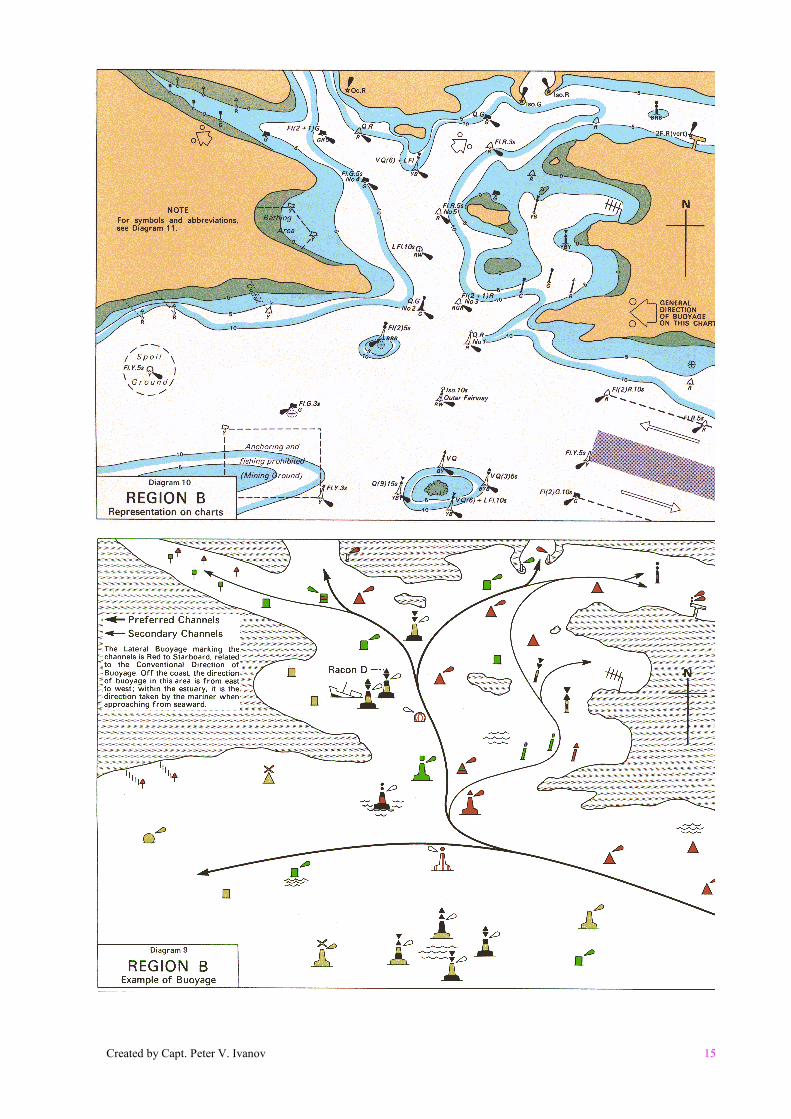
The combination of Cardinal and Lateral marks is a feature which might seem difficult to grasp at first. Diagrams 7,8, 9 and 10 illustrate ways in which the marks can be used together, and should be studied after the characteristics of
Created by Capt. Peter V. Ivanov 3
each type of mark have been mastered.
Superseded Marks
Certain marks were superseded by the introduction of the IALA System, including those for indicating wrecks; thereare no special 'landfall' or 'transition' marks in the IALA System. There is no differentiation between the marks forsuch special features as spoil grounds, anchorages, cable areas and military exercise areas, all of which will bemarked by yellow buoys which may, in addition, carry lettering to indicate the purpose of the buoy.
Characteristics of Marks
The significance of a mark depends on one or more features:
By day—Colour, shape and topmark. By night—Light colour and rhythm.
Colours of Marks
The colours red and green are reserved for Lateral marks, and yellow for Special marks. The other types of markhave black and yellow or black and red horizontal bands or red and white vertical stripes, as described later.
Shapes of Marks
There are five basic buoy shapes, namely, can, conical, spherical, pillar and spar. In the case of can, conical andspherical, the shape indicates the correct side to pass. With pillar and spar buoys, the shape has no such specialsignificance.
The term 'pillar' is used to describe any buoy which is smaller than a lanby and which has a tall central structure on abroad base; it includes beacon buoys, high focal plane buoys and others (except spar buoys) whose body shape doesnot indicate the correct side to pass.
It must be understood that, even after the introduction of the new Buoyage System, much existing equipment willcontinue to be used, including, for example, light-floats. Variations on the basic shapes, therefore, are fairlycommon but, by day, the colours and topmarks prevent ambiguity.
Topmarks
The IALA System makes use of can, conical, spherical and X-shaped topmarks only. Topmarks on pillar and sparbuoys are particularly important and are used wherever practicable, but ice or other severe conditions mayoccasionally prevent their use.
Colours of Lights
Where marks are lighted, red and green lights are reserved for Lateral marks and yellow for Special marks. Theother types of mark have a white light, distinguished one from another by rhythm.
Rhythms of Lights
Red and green lights may have any rhythm, as the colour alone is sufficient to show on which side they should bepassed. Special marks, when lighted, have a yellow light with any rhythm not reserved for white lights of thesystem. The other types of mark have clearly specified rhythms of white light: various quick flashing rhythms forCardinal marks, group-flashing (2) for Isolated Danger marks, and relatively long periods of light for Safe Watermarks.
Some shore lights, specifically excluded from the IALA System, may, by coincidence, have characteristicscorresponding to those approved for use with the new marks. Care is needed to ensure that, on sight, such lights arenot misinterpreted.
Created by Capt. Peter V. Ivanov 4
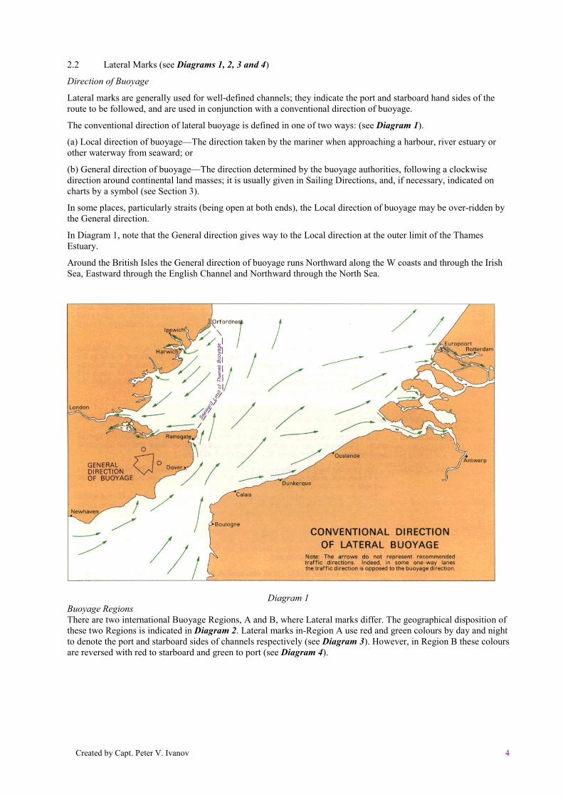
2.2 Lateral Marks (see Diagrams 1, 2, 3 and 4)
Direction of Buoyage
Lateral marks are generally used for well-defined channels; they indicate the port and starboard hand sides of theroute to be followed, and are used in conjunction with a conventional direction of buoyage.
The conventional direction of lateral buoyage is defined in one of two ways: (see Diagram 1).
(a) Local direction of buoyage—The direction taken by the mariner when approaching a harbour, river estuary orother waterway from seaward; or
(b) General direction of buoyage—The direction determined by the buoyage authorities, following a clockwisedirection around continental land masses; it is usually given in Sailing Directions, and, if necessary, indicated oncharts by a symbol (see Section 3).
In some places, particularly straits (being open at both ends), the Local direction of buoyage may be over-ridden bythe General direction.
In Diagram 1, note that the General direction gives way to the Local direction at the outer limit of the ThamesEstuary.
Around the British Isles the General direction of buoyage runs Northward along the W coasts and through the IrishSea, Eastward through the English Channel and Northward through the North Sea.
Diagram 1Buoyage RegionsThere are two international Buoyage Regions, A and B, where Lateral marks differ. The geographical disposition ofthese two Regions is indicated in Diagram 2. Lateral marks in-Region A use red and green colours by day and nightto denote the port and starboard sides of channels respectively (see Diagram 3). However, in Region B these coloursare reversed with red to starboard and green to port (see Diagram 4).

Created by Capt. Peter V. Ivanov 5
IALA MARITIME BUOYAGE SYSTEMBuoyage Regions A and B, November 1980
Diagram 2
Created by Capt. Peter V. Ivanov 6
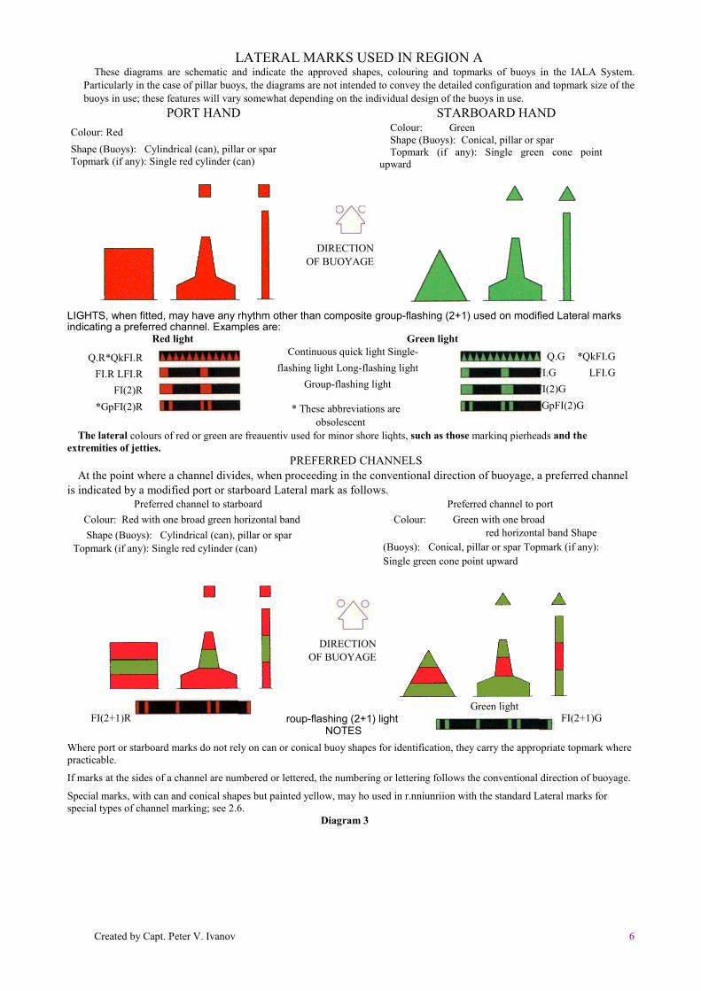
LATERAL MARKS USED IN REGION AThese diagrams are schematic and indicate the approved shapes, colouring and topmarks of buoys in the IALA System.
Particularly in the case of pillar buoys, the diagrams are not intended to convey the detailed configuration and topmark size of thebuoys in use; these features will vary somewhat depending on the individual design of the buoys in use.
PORT HANDColour: RedShape (Buoys): Cylindrical (can), pillar or sparTopmark (if any): Single red cylinder (can)
STARBOARD HANDColour: GreenShape (Buoys): Conical, pillar or sparTopmark (if any): Single green cone point
upward
LIGHTS, when fitted, may have any rhythm other than composite group-flashing (2+1) used on modified Lateral marksindicating a preferred channel. Examples are:
Red light Green lightContinuous quick light Single-
flashing light Long-flashing lightGroup-flashing light
* These abbreviations areobsolescent
The lateral colours of red or green are freauentiv used for minor shore liqhts, such as those markinq pierheads and theextremities of jetties.
PREFERRED CHANNELSAt the point where a channel divides, when proceeding in the conventional direction of buoyage, a preferred channel
is indicated by a modified port or starboard Lateral mark as follows.Preferred channel to starboard
Colour: Red with one broad green horizontal band Shape (Buoys): Cylindrical (can), pillar or spar
Topmark (if any): Single red cylinder (can)
Preferred channel to portColour: Green with one broad
red horizontal band Shape(Buoys): Conical, pillar or spar Topmark (if any):Single green cone point upward
Where port or starboard marks do not rely on can or conical buoy shapes for identification, they carry the appropriate topmark wherepracticable.
If marks at the sides of a channel are numbered or lettered, the numbering or lettering follows the conventional direction of buoyage.
Special marks, with can and conical shapes but painted yellow, may ho used in r.nniunriion with the standard Lateral marks forspecial types of channel marking; see 2.6.
Diagram 3
DIRECTIONOF BUOYAGE
Q.R*QkFI.RFI.R LFI.R
FI(2)R*GpFI(2)R
Q.G *QkFI.GFI.G LFI.GFI(2)G*GpFI(2)G
DIRECTIONOF BUOYAGE
Red light Green lightFI(2+1)R roup-flashing (2+1) light
NOTESFI(2+1)G

Created by Capt. Peter V. Ivanov 7
LATERAL MARKS USED IN REGION BThese diagrams are schematic and indicate the approved shapes, colouring and topmarks of buoys in the 1ALA System.
Particularly in the case of pillar buoys, the diagrams are not intended to convey the detailed configuration and topmark size of thebuoys in use; these features will vary somewhat depending on the individual design of the buoys in use.
PORT HANDColour: GreenShape (Buoys): Cylindrical (can), pillar or spar
Topmark (if any): Single green cylinder (can)
STARBOARD HANDColour: RedShape (Buoys): Conical, pillar or sparTopmark (if any): Single red cone point upward
LIGHTS, when fitted, may have any rhythm other than composite group-flashing (2+1) used on modified Lateral marksindicating a preferred channel. Examples are:
Continuous quick lightSingle-flashing light Long-
flashing light Group-flashing light
The lateral colours of red or green are frequently used for minor shore lights, such as those marking pierheads and the extremities ofjetties.
PREFERRED CHANNELSAt the point where a channel divides, when proceeding in the conventional direction of buoyage, a preferred channel is
indicated by a modified port or starboard Lateral mark as follows.Preferred channel to starboard
Colour: Green with one broad red horizontal bandShape (Buoys): Cylindrical (can), pillar or spar Topmark(if any): Single green cylinder (can)
Preferred channel to portColour: Red with one broad green horizontal band
Shape (Buoys): Conical, pillar or sparTopmark (if any): Single red cone point upward
Group-flashing (2+1) light
NOTESWhere port or starboard marks do not rely on can or conical buoy shapes for identification, they carry the
appropriate topmark where practicable.If marks at the sides of a channel are numbered or lettered, the numbering or lettering follows the conventional
direction of buoyage.Special marks, with can and conical shapes but painted yellow, may be used in conjunction with the standard
Lateral marks for special types of channel marking; see 2.6.
Diagram 4

Created by Capt. Peter V. Ivanov 8
2.3 Cardinal Marks (see Diagram 5)
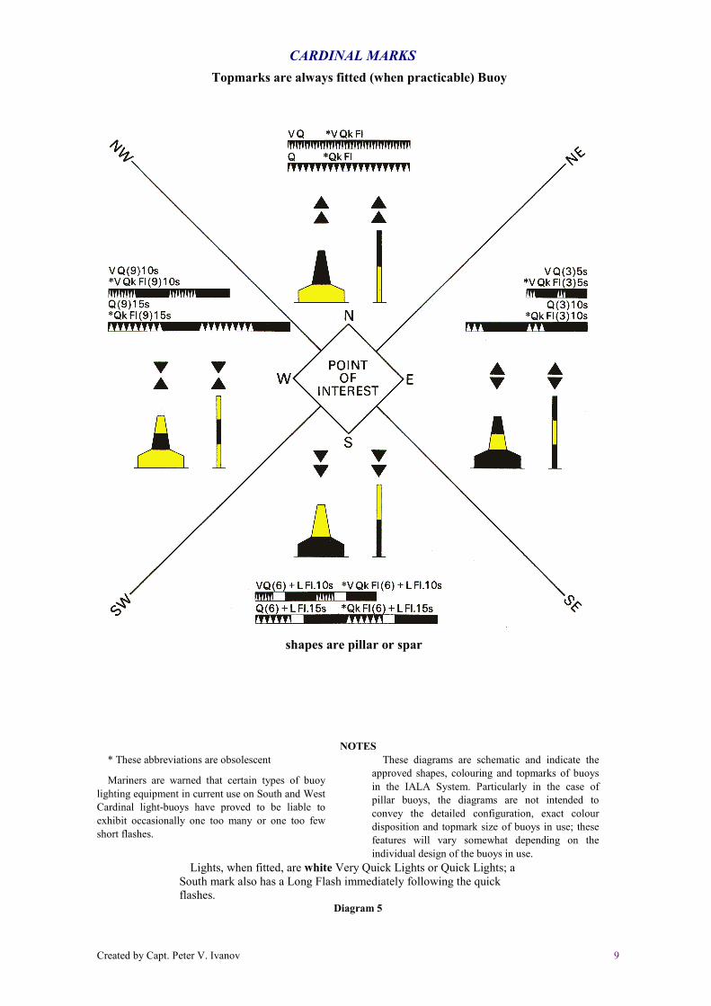
Names of MarksA Cardinal mark is used in conjunction with the compass to indicate where the mariner may find the bestnavigable water. It is placed in one of the four quadrants (North, East, South and West), bounded by the truebearings NW-NE, NE-SE, SE-SW, SW-NW, taken from the point of interest. A Cardinal mark takes its namefrom the quadrant in which it is placed.The mariner is safe if he passes N of a North mark, E of an East mark, S of a South mark and W of a Westmark.
Uses
A Cardinal mark may be used to:Indicate that the deepest water in an area is on the named side of the mark;Indicate the safe side on which to pass a danger;Draw attention to a feature in a channel such as a bend, junction, bifurcation, or end of a shoal.
TopmarksBlack double-cone topmarks are a very important feature, by day, of Cardinal marks:the arrangement of the cones must be memorised.
More difficult to remember than North ( ) and South ( ) are the East ( ) and West ( )topmarks: W tor Wineglass may help.
Cardinal marks carry topmarks whenever practicable, with the cones as large as possible and clearly separated.
ColoursBlack and yellow horizontal bands are used to colour a Cardinal mark. The position of the black band, orbands, is related to the points of the black topmarks, thus:North—Points up Black band above yellow band.South—Points down Black band below yellow band.West —Points inward Black band with yellow bands above and below.East —Points outward Black bands above and below yellow bandShapеThe shape of a Cardinal mark is not significant, but in the case of a buoy it is a pillar or spar.LightsWhen lighted, a Cardinal mark exhibits a white light; its characteristics are based on a group of quick or veryquick flashes which distinguish it as a Cardinal mark and indicate its quadrant.The distinguishing quick or very quick flashes are:North—Uninterrupted.East —3 flashes in a group.South—6 flashes in a group followed by a long flash.West —9 flashes in a group.To aid the memory, the number of flashes in each group can be associated with a clock face (3 o'clock—E, 6o'clock—S, and 9 o'clock—W).The long flash (of not less than 2 seconds duration), immediately following the group of flashes of a SouthCardinal mark, is to ensure that its 6 flashes cannot be mistaken for 3 or 9.The periods of the East, South and West lights are, respectively, 10, 15 and 15 seconds if a quick light and 5,10 and 10 seconds if a very quick light.Quick lights flash at a rate between 50 and 79 flashes per minute, usually either 50 or 60. Very quick lightsflash at a rate between 80 and 159 flashes per minute, usually either 100 or 120.It is necessary to have a choice of Quick or Very Quick lights in order to avoid confusion if, for example, twoNorth buoys are placed near enough to each other for one to be mistaken for the other.
Created by Capt. Peter V. Ivanov 9
CARDINAL MARKSTopmarks are always fitted (when practicable) Buoy
shapes are pillar or spar
NOTES* These abbreviations are obsolescent
Mariners are warned that certain types of buoylighting equipment in current use on South and WestCardinal light-buoys have proved to be liable toexhibit occasionally one too many or one too fewshort flashes.
These diagrams are schematic and indicate theapproved shapes, colouring and topmarks of buoysin the IALA System. Particularly in the case ofpillar buoys, the diagrams are not intended toconvey the detailed configuration, exact colourdisposition and topmark size of buoys in use; thesefeatures will vary somewhat depending on theindividual design of the buoys in use.
Lights, when fitted, are white Very Quick Lights or Quick Lights; aSouth mark also has a Long Flash immediately following the quickflashes.
Diagram 5
Created by Capt. Peter V. Ivanov 10
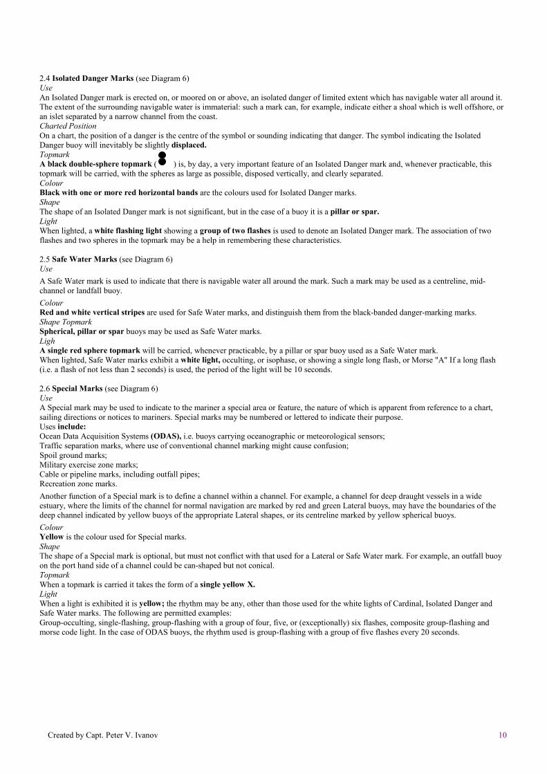
2.4 Isolated Danger Marks (see Diagram 6)UseAn Isolated Danger mark is erected on, or moored on or above, an isolated danger of limited extent which has navigable water all around it.The extent of the surrounding navigable water is immaterial: such a mark can, for example, indicate either a shoal which is well offshore, oran islet separated by a narrow channel from the coast.Charted PositionOn a chart, the position of a danger is the centre of the symbol or sounding indicating that danger. The symbol indicating the IsolatedDanger buoy will inevitably be slightly displaced.TopmarkA black double-sphere topmark ( ) is, by day, a very important feature of an Isolated Danger mark and, whenever practicable, thistopmark will be carried, with the spheres as large as possible, disposed vertically, and clearly separated.ColourBlack with one or more red horizontal bands are the colours used for Isolated Danger marks.ShapeThe shape of an Isolated Danger mark is not significant, but in the case of a buoy it is a pillar or spar.LightWhen lighted, a white flashing light showing a group of two flashes is used to denote an Isolated Danger mark. The association of twoflashes and two spheres in the topmark may be a help in remembering these characteristics.
2.5 Safe Water Marks (see Diagram 6)UseA Safe Water mark is used to indicate that there is navigable water all around the mark. Such a mark may be used as a centreline, mid-channel or landfall buoy.ColourRed and white vertical stripes are used for Safe Water marks, and distinguish them from the black-banded danger-marking marks.Shape TopmarkSpherical, pillar or spar buoys may be used as Safe Water marks.LighA single red sphere topmark will be carried, whenever practicable, by a pillar or spar buoy used as a Safe Water mark.When lighted, Safe Water marks exhibit a white light, occulting, or isophase, or showing a single long flash, or Morse "A" If a long flash(i.e. a flash of not less than 2 seconds) is used, the period of the light will be 10 seconds.
2.6 Special Marks (see Diagram 6)UseA Special mark may be used to indicate to the mariner a special area or feature, the nature of which is apparent from reference to a chart,sailing directions or notices to mariners. Special marks may be numbered or lettered to indicate their purpose.Uses include:Ocean Data Acquisition Systems (ODAS), i.e. buoys carrying oceanographic or meteorological sensors;Traffic separation marks, where use of conventional channel marking might cause confusion;Spoil ground marks;Military exercise zone marks;Cable or pipeline marks, including outfall pipes;Recreation zone marks.Another function of a Special mark is to define a channel within a channel. For example, a channel for deep draught vessels in a wideestuary, where the limits of the channel for normal navigation are marked by red and green Lateral buoys, may have the boundaries of thedeep channel indicated by yellow buoys of the appropriate Lateral shapes, or its centreline marked by yellow spherical buoys.ColourYellow is the colour used for Special marks.ShapeThe shape of a Special mark is optional, but must not conflict with that used for a Lateral or Safe Water mark. For example, an outfall buoyon the port hand side of a channel could be can-shaped but not conical.TopmarkWhen a topmark is carried it takes the form of a single yellow X.LightWhen a light is exhibited it is yellow; the rhythm may be any, other than those used for the white lights of Cardinal, Isolated Danger andSafe Water marks. The following are permitted examples:Group-occulting, single-flashing, group-flashing with a group of four, five, or (exceptionally) six flashes, composite group-flashing andmorse code light. In the case of ODAS buoys, the rhythm used is group-flashing with a group of five flashes every 20 seconds.

Created by Capt. Peter V. Ivanov 11
ISOLATED DANGER MARKS
SAFE WATER MARKS
Topmark(if the buoy is not
spherical, this is a veryimportant feature by dayand is fitted whereverpracticable)Shape: spherical or
pillar or spar
SPECIAL MARKS
Topmark(This is a very importantfeature by day and isfitted wherever practicable)
Shape: pillar or spar
Light, when fitted, is white,Group-flashing (2)
Light, when fitted, is whiteIsophase, or Occulting, or Long-flashing every 10 seconds, orMorse A.
Topmark(if fitted)
Shape: optional
Topmark(if fitted)
If these shapes are used theywill indicate the side on whichthe buoys should be passed
Light, when fitted, is yellow, andmay have any rhythm not used forwhite lights
Examples
* These abbreviations are obsolescent
NOTEThese diagrams are schematic and indicate the approved shapes, colouring and topmarks of buoys in the IALA
System. Particularly in the case of pillar buoys, the diagrams are not intended to convey the detailed configuration,exact colour disposition and topmark size of the buoys in use; these features will vary somewhat, depending on theindividual design of the buoys in use.
Diagram 6
Created by Capt. Peter V. Ivanov 12
2.7 New Dangers (see Diagrams 7 and 9)
DefinitionA newly discovered hazard to navigation not yet shown on charts, or included in sailing directions, or sufficiently promulgatedby notices to mariners, is termed a New Danger. The term covers naturally occurring obstructions such as sandbanks or rocks, orman-made dangers such as wrecks.
MarkingA New Danger is marked by one or more Cardinal or Lateral marks in accordance with the IALA System rules. If the dangeris especially grave, at least one of the marks will be duplicated as soon as practicable by an identical mark until the danger hasbeen sufficiently promulgated.
LightsIf a lighted mark is used for a New Danger, it must exhibit a quick light or very quick light: if it is a Cardinal mark, it mustexhibit a white light; if a Lateral mark, a red or green light.
Racons The duplicate mark may carry a racon, coded Morse 'W (— • •), showing a signal length of one nautical mile on a radar display.
3. CHART SYMBOLS AND ABBREVIATIONS
(see Diagrams 8, 10 and 11)ChangesNew symbols and abbreviations, and altered ones, are being incorporated in Admiralty charts when they are corrected orreprinted for use with the IALA Buoyage System. Symbols and abbreviations shown on charts to represent older systems ofbuoyage will remain unchanged until the new System is introduced into those areas.
Conventional Direction of BuoyageWhere the conventional direction of buoyage may be open to doubt it is indicated on charts by a magenta symbol.
Pillar buoysThe various forms of buoy termed 'pillar buoy' are indicated by the symbol introduced in 1976 for this purpose.
Spar buoys and BeaconsThe symbol for a spar buoy is also used to indicate a spindle buoy. In accordance with standard practice, spar buoy symbols aresloped to distinguish them from beacon symbols which are upright.
ColoursThe shading of buoy symbols formerly used to indicate the colours of buoys is omitted. A black (i.e. filled-in) symbol is used forgreen marks and for all spar buoys and beacons; an open symbol is used for all other coloured buoys and beacon towers.The abbreviated description of the colour, or colours, of a buoy is given under the symbol.Where a buoy is coloured in bands, the colours are indicated in sequence from the top, e.g. East buoy—Black with yellowband—BYB. If the sequence of the bands is not known, or if the buoy is striped, the colours are indicated with the darker colourfirst, e.g. Safe Water buoy—Red and white stripes—RW.
Topmarks LightsTopmarks are charted boldly. Topmark symbols are inserted in solid black except when the topmark is red.The period of the light of a Cardinal mark is determined by its quadrant and by whether the light is a quick light or a very quicklight; the period is less important than its rhythm. Where space on charts is limited, and on second and smaller scale charts, theperiod may be omitted.Light-stars
Light-star symbols, formerly inserted above buoy symbols (and below the topmarks, if fitted), are omitted. This enables thetopmark symbol to stand out more clearly, and avoids confusion with the X-shaped topmarks used on some Special marks.
Light-flaresMagenta light-flares are inserted with their points adjacent to the position circles at the base of the symbols: this avoids the light-flares obscuring the topmark symbols, and is in line with international chart practice.
Radar reflectorsRadar reflectors are not affected by the IALA Buoyage Rules, but in 1976 their general significance was reconsidered in thestudy initiated by the need for new symbols. It was decided not to chart them on the introduction of the new buoyage for severalreasons: it can be assumed that most major buoys are fitted with radar reflectors (some nations have already ceased to chart themon these grounds); it is necessary to reduce the size and complexity of buoy symbols and associated legends; and it is understoodthat, in the case of Cardinal buoys, buoyage authorities site the reflector so that it cannot be mistaken for a topmark.
Promulgation of details of System 'A' symbols and abbreviationsThe symbols and abbreviations as shown in Diagram 11 are also given in 5011, Symbols and Abbreviations used on AdmiraltyCharts. Diagram 11 is also published as a separate chartlet 5044.
USER
刪劃線
USER
打字機文字
D

Created by Capt. Peter V. Ivanov 13

Created by Capt. Peter V. Ivanov 14
Created by Capt. Peter V. Ivanov 15

Created by Capt. Peter V. Ivanov 16
4. IMPLEMENTATION OF THE IALA MARITIME BUOYAGE SYSTEM
Introduction of the new buoyage began in the Dover Strait in 1977. By the end of 1982 the process will have been completed innorthwest Europe, including the Baltic Sea; in west Europe and in much of the Mediterranean Sea and the Red Sea; also inSingapore, Australia, Hong Kong, and parts of Africa, the Gulf, New Zealand, Malaysia, and Indonesia. Programmes for theother areas have been drawn up.In January of each year, the latest information about the progress to date, the programme for the coming twelve months, and thelong term schedule, is given in Admiralty Notices to Mariners. The notice is accompanied by a chartlet illustrating the areasaffected in each annual stage.Detailed information about the Admiralty charts affected in each year and the arrangements being made for their correction isalso announced in Notices to Mariners. Preliminary Notices may be issued to give details of the proposed new buoys and shoremarks.Amendments to individual charts affected are promulgated through normal channels, using the most appropriate method in eachcase, i.e. New Edition, Notices to Mariners Block or Notice to Mariners. As far as is practicable, the issue of these amendments isco-ordinated with the change-over schedule of the buoyage authorities.However, the need to allow time for world-wide distribution may result in the amended charts being available to some mariners afew weeks before the actual changes take place. Normally, the issue of a New Edition automatically cancels an existing chart.However, until all the changes affecting a chart have taken place, the cancelled version should be retained for reference withrespect to buoyage.Confirmation that the buoyage changes in specific areas have been carried out will normally be announced in Radio NavigationalWarnings and in Notices to Mariners.