Iai msel pc-pg_catalog
11
MSEL -PC/PG Program Controller for ROBO Cylinder RCP5/RCP4/RCP3/RCP2 ELECTROMATE Toll Free Phone (877) SERVO98 Toll Free Fax (877) SERV099 www.electromate.com [email protected] Sold & Serviced By:
-
Upload
electromate -
Category
Technology
-
view
202 -
download
1
Transcript of Iai msel pc-pg_catalog
MSEL-PC/PGProgram Controller for ROBO Cylinder
RCP5/RCP4/RCP3/RCP2
ELECTROMATEToll Free Phone (877) SERVO98
Toll Free Fax (877) SERV099www.electromate.com
Sold & Serviced By:
1
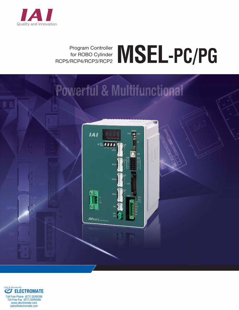
By applying to PowerCON, it is now possible to perform interpolation operation with ROBO Cylinders RCP5 and RCP4, which are applicable for high-output driver, but were not feasible with the program controllerPSEL in the past.
(*1) Note that the number of points available for backup in system memory is 10,000 points.
Actuators with pulse motor in the past were able to control only up to two axes at maximum with one program controller. By using MSEL, four axes will be available for control. It is also available for interpolation operation, which enhances the ways of use.
The feature has been greatly upgraded with four times as many programs and twenty times as many positions compared to our products (PSEL) in the past.
Control Maximum of 4 Axes Available with Pulse Motor Mounted ROBO Cylinder
Available to Connect ROBO Cylinders RCP5 and RCP4
Introducing the ROBO Cylinder 4-axis Program Controller
MSEL with High-output Driver (PowerCON)
1
2
3
Example of Combinations
+
3-axis Cartesian (Pulse Motor) RCP5
Available to Connect 4 Axes at Maximun
Available to Connect ROBO Cylinders RCP5 and RCP4Available to Connect ROBO Cylinders RCP5 and RCP4
Conventional product PSEL New product MSEL
Number of programs 64 255
Number of program steps
2,000 9,999
Number of multi-tasking programs
8 16
Number of positions 1,500 30,000 (*1)
4 times
5 times
2 times
20 times
Greatly Enhanced Programing Feature
ELECTROMATEToll Free Phone (877) SERVO98
Toll Free Fax (877) SERV099www.electromate.com
Sold & Serviced By:
2
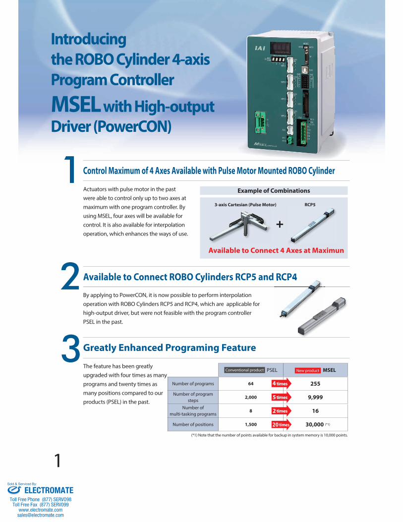
In addition to the standard IO (IN 16 points / OUT 16 points), one slot is available as the expansion I/O slot. The expansion I/O is available to select from PIO (IN 16 points / OUT 16 points) and four types of fi eld network.
67
Conventional product PSEL New product MSEL
Max. I/O Input and Output Points
24/8Not applicable for expansion
32/32When expansion slot used
Field Network 3 types(CC-Link, DeviceNet, PROFIBUS-DP)
4 types(CC-Link, DeviceNet, PROFIBUS-DP, EtherNet/IP)
Other External Connections
RS232C: 1ch RS232C: 1ch
In 4-Axis Controlling of Actuator
159
210.5
30 30
195
130
MSEL-PG is applicable for Safety Category 3.(To apply with Safety Category, it is necessary that the user establish a safety circuit out of the controller.)
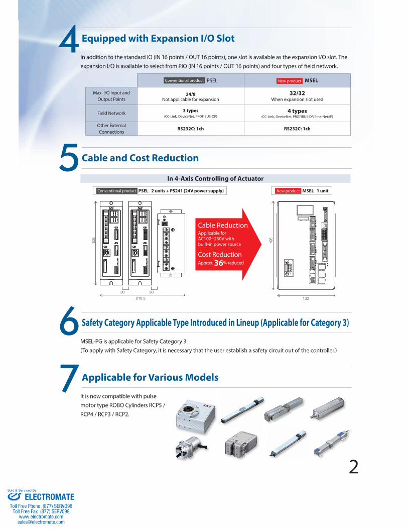
It is now compatible with pulse motor type ROBO Cylinders RCP5 / RCP4 / RCP3 / RCP2.
2
Conventional product PSEL 2 units + PS241 (24V power supply) New product MSEL 1 unit
Cable ReductionApplicable for AC100~230V with built-in power source
Cost ReductionApprox. 36% reduced
Applicable for Various Models
Cable and Cost Reduction
Equipped with Expansion I/O Slot
Safety Category Applicable Type Introduced in Lineup (Applicable for Category 3)
5
4
ELECTROMATEToll Free Phone (877) SERVO98
Toll Free Fax (877) SERV099www.electromate.com
Sold & Serviced By:
3
MSEL Controller
Type name PC PG
Name Standard type Safety Category type
External view
Maximun number of controlled axes 4
Number of positions 30,000
Power supply Single-phase AC100~230V
Safety category B 3*1
Standard price
Battery-less absolute Incremental
1 axis —
2 axes —
3 axes —
4 axes —
Simple absolute
1 axis —
2 axes —
3 axes —
4 axes —
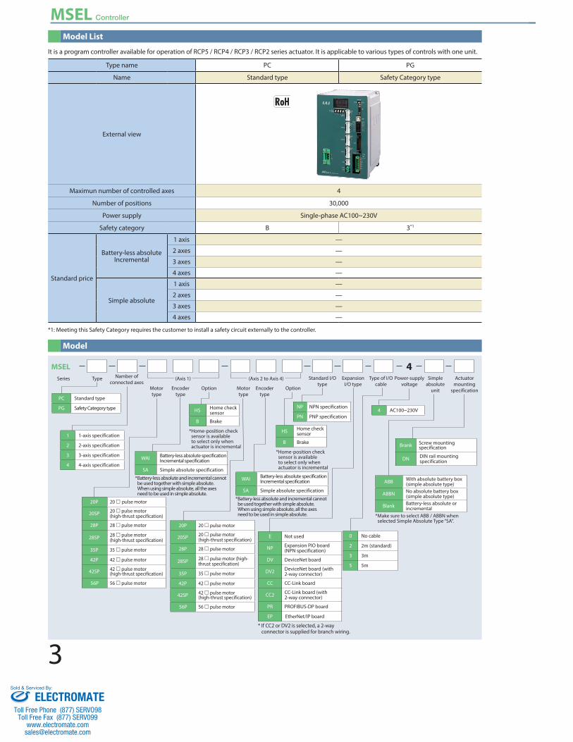
It is a program controller available for operation of RCP5 / RCP4 / RCP3 / RCP2 series actuator. It is applicable to various types of controls with one unit.
*1: Meeting this Safety Category requires the customer to install a safety circuit externally to the controller.
Model List
Model
MSEL 4TypeSeries Namber of
connected axes(Axis 1) (Axis 2 to Axis 4)
1 1-axis specification
2 2-axis specification
3 3-axis specification
4 4-axis specification
Motor type
HS Home check sensor
B Brake
* Home-position check sensor is available to select only when actuator is incremental
0 No cable
2 2m (standard)
3 3m
5 5m
4 AC100~230V
ABB With absolute battery box (simple absolute type)
ABBN No absolute battery box (simple absolute type)
Blank Battery-less absolute or incremental
* Make sure to select ABB / ABBN when selected Simple Absolute Type “SA”.
WAI Battery-less absolute specification Incremental specification
SA Simple absolute specification
* Battery-less absolute and incremental cannot be used together with simple absolute. When using simple absolute, all the axes need to be used in simple absolute.
PC Standard type
PG Safety Category type
20P 20 pulse motor
20SP 20 pulse motor (high-thrust specification)
28P 28 pulse motor
28SP 28 pulse motor (high-thrust specification)
35P 35 pulse motor
42P 42 pulse motor
42SP 42 pulse motor (high-thrust specification)
56P 56 pulse motor
20P 20 pulse motor
20SP 20 pulse motor (high-thrust specification)
28P 28 pulse motor
28SP 28 pulse motor (high-thrust specification)
35P 35 pulse motor
42P 42 pulse motor
42SP 42 pulse motor (high-thrust specification)
56P 56 pulse motor
Encoder type
Option Encoder type
OptionMotor type
Standard I/O type
Expansion I/O type
Type of I/O cable
Power-supply voltage
Simple absolute
unit
Actuator mounting
specification
HS Home check sensor
B Brake
* Home-position check sensor is available to select only when actuator is incremental
NP NPN specification
PN PNP specification
Brank Screw mounting specification
DN DIN rail mounting specification
WAI Battery-less absolute specification Incremental specification
SA Simple absolute specification
* Battery-less absolute and incremental cannot be used together with simple absolute. When using simple absolute, all the axes need to be used in simple absolute.
* If CC2 or DV2 is selected, a 2-way connector is supplied for branch wiring.
E Not used
NP Expansion PIO board (NPN specification)
DV DeviceNet board
DV2 DeviceNet board (with 2-way connector)
CC CC-Link board
CC2 CC-Link board (with 2-way connector)
PR PROFIBUS-DP board
EP EtherNet/IP board
ELECTROMATEToll Free Phone (877) SERVO98
Toll Free Fax (877) SERV099www.electromate.com
Sold & Serviced By:
4
MSEL Controller
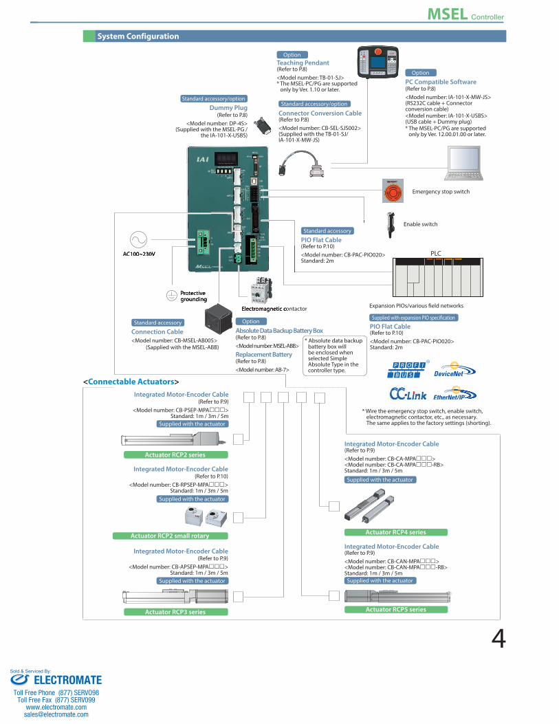
Emergency stop switch
Enable switch
PLC
Expansion PIOs/various field networks
Supplied with expansion PIO specification
PIO Flat Cable (Refer to P.10)<Model number: CB-PAC-PIO020>Standard: 2m
Actuator RCP2 series
Supplied with the actuator
Integrated Motor-Encoder Cable (Refer to P.9)
<Model number: CB-PSEP-MPA> Standard: 1m / 3m / 5m
Actuator RCP3 series
Supplied with the actuator
Integrated Motor-Encoder Cable(Refer to P.9)
<Model number: CB-APSEP-MPA> Standard: 1m / 3m / 5m
Actuator RCP4 series
Supplied with the actuator
Integrated Motor-Encoder Cable(Refer to P.9)<Model number: CB-CA-MPA> <Model number: CB-CA-MPA-RB> Standard: 1m / 3m / 5m
Actuator RCP5 series
Supplied with the actuator
Integrated Motor-Encoder Cable(Refer to P.9)<Model number: CB-CAN-MPA> <Model number: CB-CAN-MPA-RB> Standard: 1m / 3m / 5m
Actuator RCP2 small rotary
Supplied with the actuator
Integrated Motor-Encoder Cable (Refer to P.10)
<Model number: CB-RPSEP-MPA> Standard: 1m / 3m / 5m
AC100~230V
Protective grounding
Electromagnetic contactor
Standard accessory/optionStandard accessory/optionDummy Plug
(Refer to P.8) <Model number: DP-4S>
(Supplied with the MSEL-PG / the IA-101-X-USBS)
Connector Conversion Cable (Refer to P.8)<Model number: CB-SEL-SJS002>(Supplied with the TB-01-SJ/IA-101-X-MW-JS)
PC Compatible Software(Refer to P.8)<Model number: IA-101-X-MW-JS> (RS232C cable + Connector conversion cable)<Model number: IA-101-X-USBS>(USB cable + Dummy plug) * The MSEL-PC/PG are supported
only by Ver. 12.00.01.00 or later.
Teaching Pendant(Refer to P.8)<Model number: TB-01-SJ>* The MSEL-PC/PG are supported
only by Ver. 1.10 or later.
AC100~230V
Protective grounding
Electromagnetic contactor
System Configuration
Connection Cable <Model number: CB-MSEL-AB005>
(Sapplied with the MSEL-ABB)
Standard accessory
PIO Flat Cable (Refer to P.10)<Model number: CB-PAC-PIO020>Standard: 2m
* Wire the emergency stop switch, enable switch, electromagnetic contactor, etc., as necessary. The same applies to the factory settings (shorting).
Standard accessory
* Absolute data backup battery box will be enclosed when selected Simple Absolute Type in the controller type.
Absolute Data Backup Battery Box(Refer to P.8)<Model number: MSEL-ABB> Replacement Battery(Refer to P.8)<Model number: AB-7>
Option
Option
Option
<Connectable Actuators>
ELECTROMATEToll Free Phone (877) SERVO98
Toll Free Fax (877) SERV099www.electromate.com
Sold & Serviced By:
5
MSEL Controller
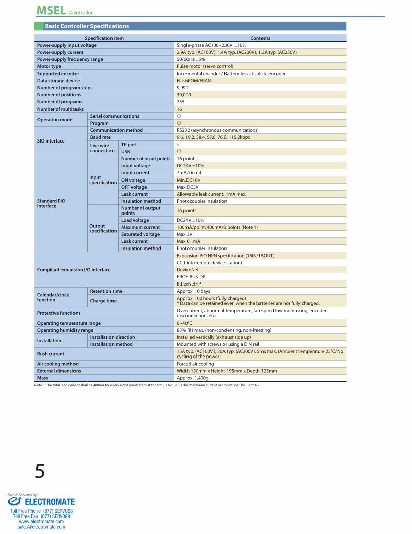
Basic Controller Specifications
Specification item ContentsPower-supply input voltage Single-phase AC100~230V ±10%Power-supply current 2.9A typ. (AC100V), 1.4A typ. (AC200V), 1.2A typ. (AC230V)Power-supply frequency range 50/60Hz ±5%Motor type Pulse motor (servo control)Supported encoder Incremental encoder / Battery-less absolute encoderData storage device FlashROM/FRAMNumber of program steps 9,999Number of positions 30,000Number of programs 255Number of multitasks 16
Operation modeSerial communications
Program
SIO interface
Communication method RS232 (asynchronous communications) Baud rate 9.6, 19.2, 38.4, 57.6, 76.8, 115.2kbps
Live wire connection
TP port ×USB
Standard PIO interface
Input specification
Number of input points 16 pointsInput voltage DC24V ±10%Input current 7mA/circuitON voltage Min.DC16VOFF voltage Max.DC5VLeak current Allowable leak current: 1mA max.Insulation method Photocoupler insulation
Output specification
Number of output points 16 points
Load voltage DC24V ±10%Maximum current 100mA/point, 400mA/8 points (Note 1)Saturated voltage Max.3VLeak current Max.0.1mAInsulation method Photocoupler insulation
Compliant expansion I/O interface
Expansion PIO NPN specification (16IN/16OUT)CC-Link (remote device station)DeviceNetPROFIBUS-DPEtherNet/IP
Calendar/clock function
Retention time Approx. 10 days
Charge time Approx. 100 hours (fully charged) * Data can be retained even when the batteries are not fully charged.
Protective functions Overcurrent, abnormal temperature, fan speed low monitoring, encoder disconnection, etc.
Operating temperature range 0~40°COperating humidity range 85% RH max. (non-condensing, non-freezing)
InstallationInstallation direction Installed vertically (exhaust side up)Installation method Mounted with screws or using a DIN rail
Rush current 15A typ. (AC100V ), 30A typ. (AC200V): 5ms max. (Ambient temperature 25°C/No cycling of the power)
Air cooling method Forced air coolingExternal dimensions Width 130mm x Height 195mm x Depth 125mmMass Approx. 1,400g
Note 1: The total load current shall be 400mA for every eight points from standard I/O No. 316. (The maximum current per point shall be 100mA.)
ELECTROMATEToll Free Phone (877) SERVO98
Toll Free Fax (877) SERV099www.electromate.com
Sold & Serviced By:
6
MSEL Controller
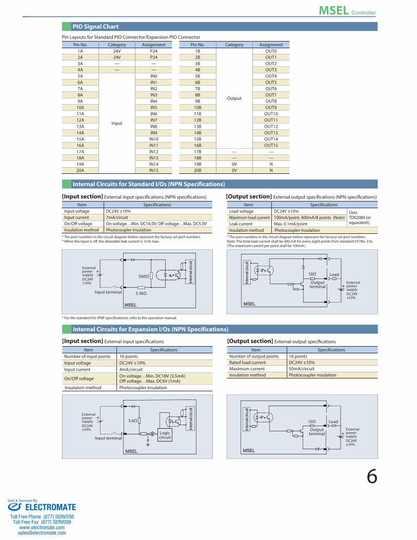
Pin No. Category Assignment Pin No. Category Assignment1A 24V P24 1B
Output
OUT02A 24V P24 2B OUT13A — — 3B OUT24A — — 4B OUT35A
Input
IN0 5B OUT46A IN1 6B OUT57A IN2 7B OUT68A IN3 8B OUT79A IN4 9B OUT8
10A IN5 10B OUT911A IN6 11B OUT1012A IN7 12B OUT1113A IN8 13B OUT1214A IN9 14B OUT1315A IN10 15B OUT1416A IN11 16B OUT1517A IN12 17B — —18A IN13 18B — —19A IN14 19B 0V N20A IN15 20B 0V N
Pin Layouts for Standard PIO Connector/Expansion PIO Connector
PIO Signal Chart
Internal Circuits for Expansion I/Os (NPN Specifications)
Item SpecificationsNumber of input points 16 pointsInput voltage DC24V ±10%Input current 4mA/circuit
On/Off voltage On voltage…Min. DC18V (3.5mA)Off voltage…Max. DC6V (1mA)
Insulation method Photocoupler insulation
Item SpecificationsNumber of output points 16 pointsRated load current DC24V ±10%Maximum current 50mA/circuitInsulation method Photocoupler insulation
[Input section] External input specifications [Output section] External output specifications
[Input section] External input specifications (NPN specifications) [Output section] External output specifications (NPN specifications)Item Specifications
Input voltage DC24V ±10%Input current 7mA/circuitOn/Off voltage On voltage…Min. DC16.0V, Off voltage…Max. DC5.0VInsulation method Photocoupler insulation
Item SpecificationsLoad voltage DC24V ±10% Uses
TD62084 (or equivalent).
Maximum load current 100mA/point, 400mA/8 points (Note)Leak current Max. 0.1mA/pointInsulation method Photocoupler insulation
* The port numbers in the circuit diagram below represent the factory-set port numbers. * When the input is off, the allowable leak current is 1mA max.
* For the standard IOs (PNP specifications), refer to the operation manual.
* The port numbers in the circuit diagram below represent the factory-set port numbers. Note: The total load current shall be 400 mA for every eight points from standard I/O No. 316. (The maximum current per point shall be 100mA.)
Internal Circuits for Standard I/Os (NPN Specifications)
560Ω
3.3kΩInput terminal
External power supplyDC24V±10% In
tern
al cir
cuit
5.6Ω
Input terminal
External power supplyDC24V±10% In
tern
al cir
cuit
Logiccircuit
10Ω
External power supplyDC24V±10%
Inte
rnal
circu
it
Outputterminal
Load
15Ω
External power supplyDC24V±10%
Inte
rnal
circu
it
Outputterminal
Load
ELECTROMATEToll Free Phone (877) SERVO98
Toll Free Fax (877) SERV099www.electromate.com
Sold & Serviced By:

7
MSEL Controller
*1: Do not connect a wrong motor to the MPG1, MPG2, MPG3 or MPG4 connector. It may cause malfunction or failure.
Name of Each Part
130
195
3
125
3
1164-ø4.5
185
130
195
125 1164-ø4.5
5.9
(10.
9)
(75m
m fr
om th
e ce
nter
of D
IN ra
il)3
3
185
Screw mounting specification DIN rail mounting specification
External Dimensions
MPG1
MPG4
MPG3
MPG2
Mode switch
Teaching connector
USB connector
System I/O connector
Standard I/O connector (I/O1)
Expansion I/O connector (I/O2)
Motor drive power line connector
Brake release switch
Motor/encoder connector
Power connector
*1
Absolute data backup battery connector
123
115
98111
108
10.5ø5ø5
5 5
(4)
4
10.5
35.4
(35m
m D
in ra
il with
)
(59m
m fr
om th
e ce
nter
of D
IN ra
il)
Absolute Data Backup Battery Box
Controller
ELECTROMATEToll Free Phone (877) SERVO98
Toll Free Fax (877) SERV099www.electromate.com
Sold & Serviced By:

8
MSEL Controller
PC Compatible Software (Windows Only)❙ Features The startup support software provides program/position input, test operation and monitoring functions, among others. With its enhanced functions required for debugging, this software helps shorten the startup time.
❙ Model number IA-101-X-MW-JS (RS232C cable + Connector conversion cable)❙ Configuration
❙ Model number IA-101-X-USBS (USB cable + Dummy plug)❙ Configuration
The CB-ST-E1MW050-EB cannot be used when “Building an enable system that uses a system I/O connector and external power supply” or “Building a redundant safety circuit.” (The CB-ST-A1MW050-EB must be used instead.)
The MSEL-PC/PG are supported by Ver. 12.00.01.00 or later.
Options
3m
USB cableCB-SEL-USB030
Dummy plugDP-4S
5m 0.2m
RS232C cableCB-ST-E1MW050-EB
Connector conversion cable CB-SEL-SJS002
Dummy Plug❙ Features This plug is required for the safety category specification (MSEL-PG) and when the MSEL is operated using a USB cable. (The MSEL-PG type and PC compatible software IA-101-X-USBS come with this dummy plug.)
❙ Model number DP-4SConnector Conversion Cable❙ Features This cable is used to convert the D-sub 25-pin connector of the teaching pendant or RS232C cable to the MSEL teaching connector. (The TB-01-SJ and IA-101-X-MW-JS come with this connector conversion cable.)
❙ Model number CB-SEL-SJS002
Teaching Pendant❙ Features A teaching device offering program/position input, trial operation and monitoring functions.
❙ Model number TB-01-SJ* This model is the standard specification with connector conversion
cable. If you are interested in the deadman switch specifi cation, specify the model number of the applicable teaching pendant (TB-01D-N/TB-01DR-N) and that of the cable (CB-TB1-X050-JS).
❙ Configuration
The MSEL-PC/PG are supported by Ver. 1.10 or later.
5m
Absolute Data Backup Battery Box❙ Features If the absolute position encoder specifi cation is selected with code ABB, the absolute data backup battery box is included with the controller. However, if the battery box is ordered as a separate unit, it does not include the battery but just the box itself. If the battery is needed, please purchase it separately. (Model: AB-7).
❙ Model number MSEL-ABB (Batteries not included)❙ Exterior dimensions See P.7
Replacement Battery❙ Features The replacement battery for the absolute data bakup battery box.
❙ Model number AB-7
* A cable (Model CB-MSEL-AB005) that connects the absolute data backup battery box to the MSEL is included with the box.
* Same quantity of absolute battery units is required as the number of axes.
ELECTROMATEToll Free Phone (877) SERVO98
Toll Free Fax (877) SERV099www.electromate.com
Sold & Serviced By:
9
MSEL Controller
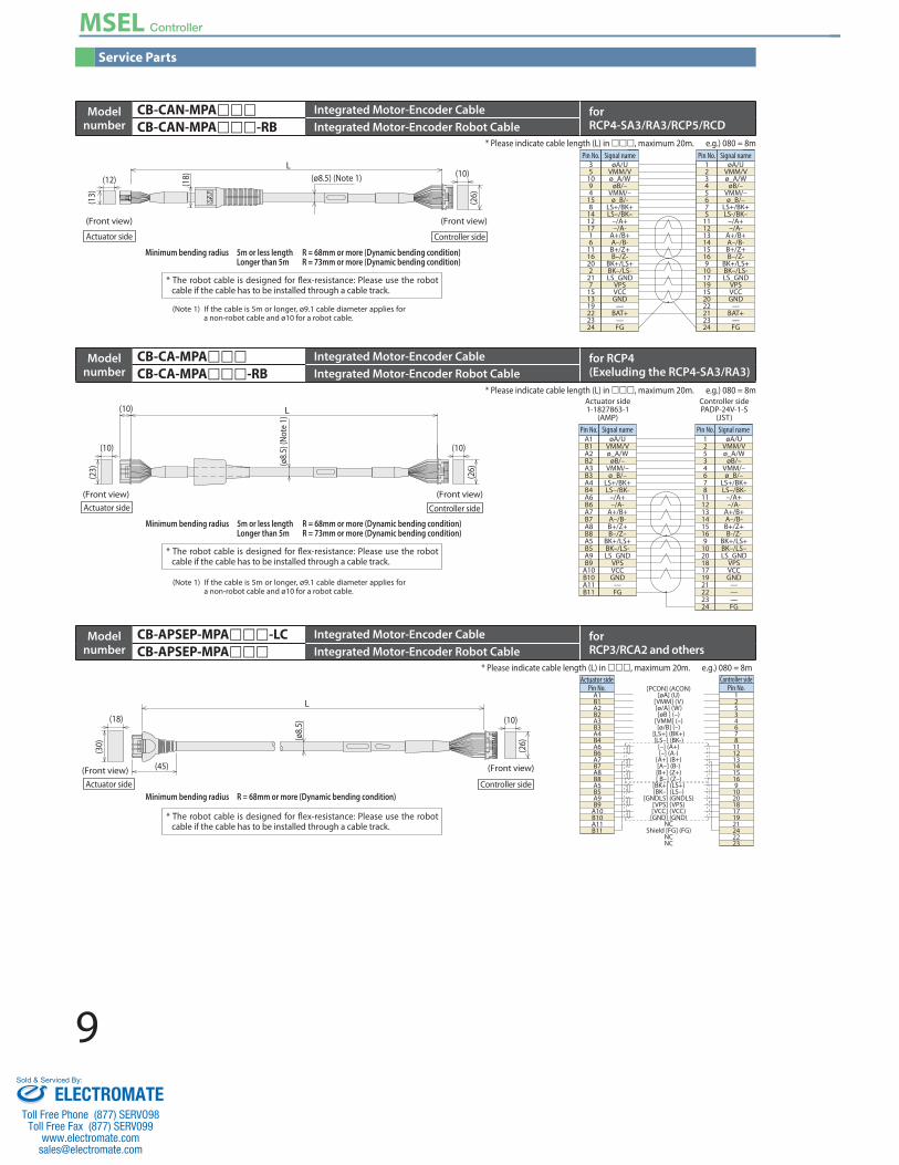
Service Parts
Actuator side1-1827863-1
(AMP)
Controller sidePADP-24V-1-S
(JST)
12534678
1112131415169
102018171921222324
A1B1A2B2A3B3A4B4A6B6A7B7A8B8A5B5A9B9
A10B10A11B11
Pin No. Pin No. Signal nameøA/U
VMM/Vø_A/W
øB/–VMM/–ø_B/–
LS+/BK+LS–/BK-
–/A+–/A-
A+/B+A–/B-B+/Z+B–/Z–
BK+/LS+BK–/LS-LS_GND
VPSVCCGND
—FG
øA/UVMM/Vø_A/W
øB/–VMM/–ø_B/–
LS+/BK+LS–/BK-
–/A+–/A-
A+/B+A–/B-B+/Z+B-/Z-
BK+/LS+BK–/LS–LS_GND
VPSVCCGND
———FG
Signal name
L
(10)
(Front view)
(10)
(23)
(10)
(26)
(ø8.
5) (N
ote
1)
Actuator side Controller side
(Front view)
Minimum bending radius 5m or less length R = 68mm or more (Dynamic bending condition) Longer than 5m R = 73mm or more (Dynamic bending condition)
* The robot cable is designed for flex-resistance: Please use the robot cable if the cable has to be installed through a cable track.
* Please indicate cable length (L) in , maximum 20m. e.g.) 080 = 8m
Actuator side Controller side
Pin No. Pin No. Signal nameøA/U
VMM/Vø_A/W
øB/–VMM/–ø_B/-
LS+/BK+LS–/BK–
–/A+–/A-
A+/B+A–/B-B+/Z+B–/Z-
BK+/LS+BK–/LS-LS_GND
VPSVCCGND
—BAT+
—FG
øA/UVMM/Vø_A/W
øB/–VMM/–ø_B/–
LS+/BK+LS-/BK–
–/A+–/A-
A+/B+A–/B-B+/Z+B–/Z-
BK+/LS+BK–/LS-LS_GND
VPSVCCGND
—BAT+
—FG
Signal name1234567S
1112131415169
1017191S2022212324
35
1094
158
14121716
1116202
217
1S1319222324
L
(Front view) (Front view)
(10)(12)
(26)
(18)
(13)
(ø8.5) (Note 1)
* Please indicate cable length (L) in , maximum 20m. e.g.) 080 = 8m
Minimum bending radius 5m or less length R = 68mm or more (Dynamic bending condition) Longer than 5m R = 73mm or more (Dynamic bending condition)
* The robot cable is designed for flex-resistance: Please use the robot cable if the cable has to be installed through a cable track.
(Note 1) If the cable is 5m or longer, ø9.1 cable diameter applies for a non-robot cable and ø10 for a robot cable.
(Note 1) If the cable is 5m or longer, ø9.1 cable diameter applies for a non-robot cable and ø10 for a robot cable.
12534678
1112131415169
102018171921242223
A1B1A2B2A3B3A4B4A6B6A7B7A8B8A5B5A9B9
A10B10A11B11
[PCON] (ACON)[øA] (U)
[VMM] (V)[ø/A] (W)[øB ] (–)
[VMM] (–)[ø/B] (–)
[LS+] (BK+)[LS–] (BK-)
[–] (A+)[–] (A-)
[A+] (B+)[A–] (B-)[B+] (Z+)[ B–] (Z–)
[BK+] (LS+)[BK–] (LS–)
[GNDLS] (GNDLS)[VPS] (VPS)[VCC] (VCC)[GND] (GND)
NCShield [FG] (FG)
NCNC
Controller sidePin No.
Actuator sidePin No.
L
(10)
(26)
(18)
(30)
(45)
(ø8.
5)
Actuator side(Front view)
Controller side
(Front view)
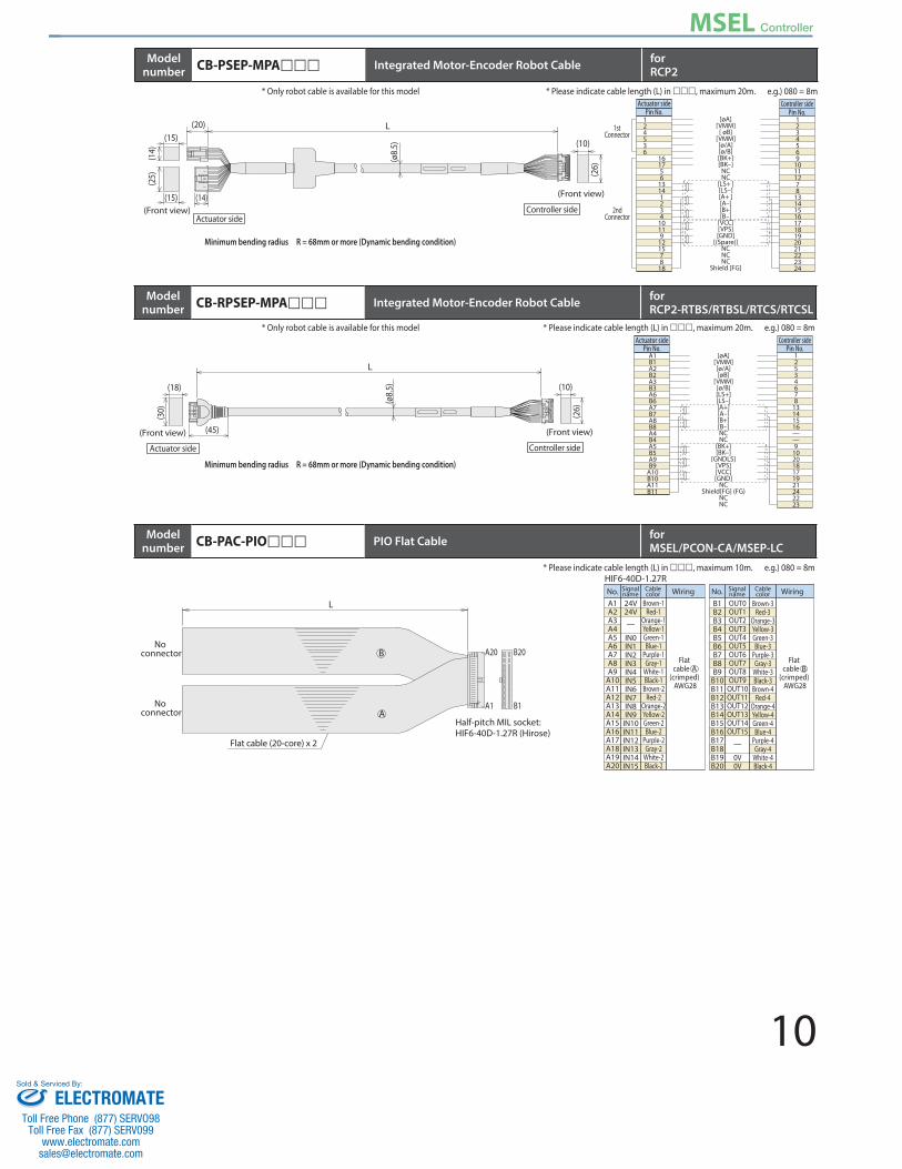
* Please indicate cable length (L) in , maximum 20m. e.g.) 080 = 8m
Minimum bending radius R = 68mm or more (Dynamic bending condition)
* The robot cable is designed for flex-resistance: Please use the robot cable if the cable has to be installed through a cable track.
Modelnumber
CB-APSEP-MPA-LC Integrated Motor-Encoder Cable for RCP3/RCA2 and others CB-APSEP-MPA Integrated Motor-Encoder Robot Cable
Modelnumber
CB-CA-MPA Integrated Motor-Encoder Cable for RCP4(Exeluding the RCP4-SA3/RA3)CB-CA-MPA-RB Integrated Motor-Encoder Robot Cable
Modelnumber
CB-CAN-MPA Integrated Motor-Encoder Cable for RCP4-SA3/RA3/RCP5/RCDCB-CAN-MPA-RB Integrated Motor-Encoder Robot Cable
ELECTROMATEToll Free Phone (877) SERVO98
Toll Free Fax (877) SERV099www.electromate.com
Sold & Serviced By:
10
MSEL Controller
A1B1A2B2A3B3A6B6A7B7A8B8A4B4A5B5A9B9
A10B10A11B11
Controller sidePin No.
Actuator sidePin No.
L
(10)
(26)
(45)
(18)
(30)
(ø8.
5)
(Front view)
Actuator side
[øA][VMM][ø/A][øB]
[VMM][ø/B][LS+][LS–][A+][A–][B+][B–]NCNC
[BK+][BK–]
[GNDLS][VPS][VCC][GND]
NCShield[FG] (FG)
NCNC
12534678
13141516——9
102018171921242223
Controller side
(Front view)
Minimum bending radius R = 68mm or more (Dynamic bending condition)
* Please indicate cable length (L) in , maximum 20m. e.g.) 080 = 8m
B20A20
B1A1
L
B
A
No connector
No connector
Flat cable (20-core) x 2
Half-pitch MIL socket:HIF6-40D-1.27R (Hirose)
HIF6-40D-1.27RNo. Signal
nameCablecolor Wiring No. Signal
nameCablecolor Wiring
Brown-1Red-1
Orange-1Yellow-1Green-1Blue-1
Purple-1Gray-1
White-1Black-1
Brown-2Red-2
Orange-2Yellow-2Green-2Blue-2
Purple-2Gray-2
White-2Black-2
24V24V—
IN0IN1IN2IN3IN4IN5IN6IN7IN8IN9
IN10IN11IN12IN13IN14IN15
A1A2A3A4A5A6A7A8A9
A10A11A12A13A14A15A16A17A18A19A20
OUT0OUT1OUT2OUT3OUT4OUT5OUT6OUT7OUT8OUT9
OUT10OUT11OUT12OUT13OUT14OUT15
—
0V0V
B1B2B3B4B5B6B7B8B9
B10B11B12B13B14B15B16B17B18B19B20
Brown-3Red-3
Orange-3Yellow-3Green-3Blue-3
Purple-3Gray-3
White-3Black-3
Brown-4Red-4
Orange-4Yellow-4Green-4Blue-4
Purple-4Gray-4
White-4Black-4
Flat cable
(crimped) AWG28
Flat cable
(crimped) AWG28
* Please indicate cable length (L) in , maximum 10m. e.g.) 080 = 8m
Modelnumber CB-RPSEP-MPA Integrated Motor-Encoder Robot Cable for
RCP2-RTBS/RTBSL/RTCS/RTCSL
Modelnumber CB-PAC-PIO PIO Flat Cable for
MSEL/PCON-CA/MSEP-LC
* Only robot cable is available for this model
1234569
10111278
131415161718192021222324
124536
161756
13141234
10119
121578
18
[øA][VMM]
[ øB][VMM][ø/A][ø/B][BK+][BK–]
NCNC
[LS+ ][LS–][A+ ][A–][B+][B–]
[VCC][VPS][GND]
[(Spare)]NCNCNC
Shield [FG]
Controller sidePin No.
Actuator sidePin No.
L
(10)
(26)
(15) (14)
(25)
(15)(1
4)
(20)
(ø8.
5)
(Front view)Actuator side
1stConnector
2ndConnector
Controller side
(Front view)
* Please indicate cable length (L) in , maximum 20m. e.g.) 080 = 8m
Minimum bending radius R = 68mm or more (Dynamic bending condition)
Modelnumber CB-PSEP-MPA Integrated Motor-Encoder Robot Cable for
RCP2* Only robot cable is available for this model
ELECTROMATEToll Free Phone (877) SERVO98
Toll Free Fax (877) SERV099www.electromate.com
Sold & Serviced By: