IAEA International Conference on Topical Issues in … New core internals with many reactor control...
26
© 2017 MITSUBISHI HEAVY INDUSTRIES, LTD. All Rights Reserved. June 7, 2017 Development for Nuclear Power Plant Safety Overview of Technology Developments for Continuous Improvements of Nuclear Safety Tomofumi YAMAMOTO Nuclear Energy Systems Division, Mitsubishi Heavy Industries, Ltd. Tokyo, Japan IAEA International Conference on Topical Issues in Nuclear Installation Safety: Safety Demonstration of Advanced Water Cooled Nuclear Power Plants (CN-251)
Transcript of IAEA International Conference on Topical Issues in … New core internals with many reactor control...

© 2017 MITSUBISHI HEAVY INDUSTRIES, LTD. All Rights Reserved.
June 7, 2017
Development for
Nuclear Power Plant Safety
Overview of Technology Developments for
Continuous Improvements of Nuclear Safety
Tomofumi YAMAMOTO
Nuclear Energy Systems Division, Mitsubishi Heavy Industries, Ltd. Tokyo, Japan
IAEA International Conference on Topical Issues in
Nuclear Installation Safety: Safety Demonstration of Advanced Water Cooled Nuclear Power Plants (CN-251)

© 2017 MITSUBISHI HEAVY INDUSTRIES, LTD. All Rights Reserved. 2
Contents
1. Introduction
2. Strengthening of Overall Nuclear Safety
3. Advances for Core Cooling Measure Using
SG Secondary-side Depressurization
4. Development of Seismic Isolation System
For Nuclear Facilities
5. Summary

1. Introduction

© 2017 MITSUBISHI HEAVY INDUSTRIES, LTD. All Rights Reserved. 4
Current Status of NPP in Japan : PWR : BWR
Kashiwazaki Kariwa
Tomari
Higashidori
Onagawa
Fukushima Daiichi
Fukushima Daini
Tokai Daini
Hamaoka
Ikata
Sendai
Shika
Tsuruga
Mihama
Ohi
Shimane
Genkai
Takahama
1 2 3
1 2 3
1 2 3 4 5 6
1
Oma 1
1
1 2 3 4 1 2 3
1
1 2
1 2 3 4 5 6 7
2
1 2 3
1 2 3
1 2 1 2 3 4
1 2 3 4
1 2 3 4
PWR BWR
Restarted 5 0
Approved by NRA 7 0
Under review by NRA 4 10
Preparing review 4 14
To be decommissioned 4 10
1 2 3 4 5

© 2017 MITSUBISHI HEAVY INDUSTRIES, LTD. All Rights Reserved. 5
New Regulatory Requirements
Natural Phenomena
Fire
Reliability of Power Supply
Reliability of Other SSCs
Seismic / Tsunami Resistance
Intentional Aircraft Crash
Suppress Radioactive Materials Dispersion
Prevent CV Failure
Prevent Core Damage (multiple failure)
Internal Flooding
Natural Phenomena (volcano, tornado, forest fire)
Fire
Reliability of Power Supply
Reliability of Other SSCs
Seismic / Tsunami Resistance
Previous
SSCs: Structure, Systems and Components CV: Containment Vessel
Focus on prevention from
severe accidents
(i.e. Regulation based on the
design basis: Regulatory body
have confirmed that a single
failure would not lead to core
damage)
Reinforced
Reinforced
&
Newly
introduced
Newly
introduced
New

2. Strengthening of Overall Nuclear Safety

© 2017 MITSUBISHI HEAVY INDUSTRIES, LTD. All Rights Reserved. 7
Developments based on the DiD
levels
of DiD Objective
Direction to strengthen
safety functions Technology developments
Level 1 Prevention of
abnormal
operation and
failures
Earthquake-resistance - Seismic isolation system
- Enhancement of seismic evaluation
method for steam generator
Level 2 Control of
abnormal
operation and
detection of
failures
Maintain subcriticality to
cold shutdown only with
control rods
- New core internals with many
reactor control clusters
- Enhancement of CFD analysis for
core internals
Level 3 Control of
accident within
the design basis
Diversity for reactor core
cooling
- Enhancement of core cooling
capability by steam generator
- Air cooling system/equipment
Level 4 Control of severe
plant conditions
Cooling of melting core - In-vessel retention for large reactor
According to the concept of Defence in Depth, the middle and long
term direction and the technology developments were surveyed.

3. Advances for Core Cooling Measure Using SG Secondary-side Depressurization

© 2017 MITSUBISHI HEAVY INDUSTRIES, LTD. All Rights Reserved. 9
原子炉容器
制御棒駆動装置
タービン
復水タンク
大気
蒸気発生器
使用済燃料ピット
給水車消火栓
地面
主蒸気逃し弁
大気
~ ~ ~ ~
発電機
復水器
~~
~~タービン動補助給水ポンプ
加圧器
一次冷却材ポンプ
原子炉格納容器
Feed Water
Gravity-driven CRD
1. Shutdown
Large volume
containment confines
radio activity and
hydrogen under accident.
3. Confinement
4. Cooling (SFP)
Water can be fed at the
ground level. 一次系自然循環
① Coolant is injected by turbine-driven pumps(Passive safety).
② SG secondary-side is cooled by the steam discharge via. MSRV.
③ Core cooling is achieved by the
primary-side natural-circulation.
2. Cooling
原子炉容器
①
②
③
Natural-circulation core cooling can be achieved by SG
secondary-side depressurization under SBO/Loss of UHS
Containment
PRZ
PV RCP
Natural circulation
SG
MSRV
Turbine- driven Pumps
Water tank
Turbine Generator
Spent Fuel Pit
Ground
Safety Measures under SBO/LUHS

© 2017 MITSUBISHI HEAVY INDUSTRIES, LTD. All Rights Reserved. 10
Hot Leg
Cold Leg
Pressurizer
Accumulator
Low Pressure Injection Pump
Steam Generator
Small Break LOCA
Cross-over Leg
Core
Main Steam Relief Valve
Key lesson learned from Fukushima Dai-ichi Accident
To secure core cooling measures
Purpose
Purpose of this study
Development of SG cooling system and procedure as an
additional safety measure in order to secure the diversity of
core cooling measures.
An example of core cooling process by SG under SB-LOCA
Time
Prim
ary
Pre
ssure
Accumulator Injection Start
Small Break LOCA occur
SI signal
SG depressurization initiation
Reactor trip
Low-pressure injection start
Early activation of SG
main steam relief valve
(MSRV) is considered
after SI signal.
The accumulator and
low-pressure injection
system are started
earlier to fulfill the core
cooling requirement
(PCT:1473K).

© 2017 MITSUBISHI HEAVY INDUSTRIES, LTD. All Rights Reserved. 11
Subjects of this study
• To show the validity of the core cooling with SG secondary-
side depressurization
• To develop an analytical method which can apply to actual
reactors
Actions to resolve the subjects
• To perform experiments using an appropriate test facility
which fulfills the requirements for scalability to actual
reactors
- Large Scale Test Facility (LSTF) at JAEA is used as
the test facility
• To validate an analytical method using the database
- M-RELAP5 is used as the analytical method
Subjects

© 2017 MITSUBISHI HEAVY INDUSTRIES, LTD. All Rights Reserved. 12
Large Scale Test Facility (LSTF) • LSTF is full-height and full-pressure (approximately 15MPa) thermal-
hydraulic simulator of typical four-loop PWR.
Test parameters to be examined • Pipe break size(2in, 4in, 6in, 8in*, 10in) • Loop-unbalance cooling
• Low pressure/Low power natural circulation
• Non-condensable gas in Accumulator
• SG secondary-side depressurization timing
*Major results will be presented.
Demonstration
LSTF
Volume Scaled by 1/48 to the reference PWR
Height corresponds to the reference PWR
Nominal
pressure corresponds to the reference PWR
Loop Two loops (One broken/ One intact)

© 2017 MITSUBISHI HEAVY INDUSTRIES, LTD. All Rights Reserved. 13
Demonstration of the core cooling under SB-LOCA
Experiment
the primary pressure decrease
along with the SG secondary-
side depressurization.
The depressurization
successfully achieves the
activation of accumulator and
low-pressure injection system.
M-RELAP5
Good predictions are obtained,
which mean that break flow
rate and the SG primary and
secondary-side thermal-
hydraulics are well simulated.
Depressurization
Primary and Secondary Pressure
Start of SG secondary-
side depressurization
Actuating level
of Accumulator

© 2017 MITSUBISHI HEAVY INDUSTRIES, LTD. All Rights Reserved. 14
Peak Cladding Temperature (PCT)
Experiment
After the Accumulator
activation the cladding
temperature turns down and
the PCT fulfills the safety
requirement (1473K). M-RELAP5
The start point of core heat-
up is earlier and the PCT is
higher than the experiment.
M-RELAP5 gives a
conservative prediction for
the PCT and can be used as
a safety evaluation code for
the actual reactor.
PCT
Demonstration of the core cooling under SB-LOCA
1000
900
800
700
600
500
400
Tem
per
atu
re (
K)
5004003002001000
Time (s)
Experiment
M-RELAP5
Experiment
M-RELAP5
Activation timing
of Accumulator

© 2017 MITSUBISHI HEAVY INDUSTRIES, LTD. All Rights Reserved. 15
Performance of SG Secondary-side Depressurization The core cooling safety measure works well under SBLOCA even if no
high-pressure injection system is activated.
Although this presentation shows only one typical case, the
depressurization system also worked well for other several parameters
(Break size, Loop-unbalance cooling, Non-condensable gas in
Accumulator, SG secondary-side depressurization timing).
Impact for Safety Advances The results of this project give the technical evidence that the AM
measure can be activated without any concerns for several
uncertainties like break size, loop-unbalance cooling, non-condensable
gas in accumulator, SG secondary-side depressurization timing.
This contributes to enhance the reliability of the AM measure and also
be useful to refine the time-margin for operator action in future.
Typical Results - Core Cooling Measure
4. Development of Seismic Isolation System for Nuclear Facilities
© 2017 MITSUBISHI HEAVY INDUSTRIES, LTD. All Rights Reserved. 17
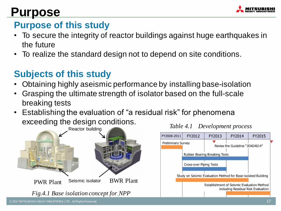
Table 4.1 Development process
Purpose of this study • To secure the integrity of reactor buildings against huge earthquakes in
the future
• To realize the standard design not to depend on site conditions.
Subjects of this study • Obtaining highly aseismic performance by installing base-isolation
• Grasping the ultimate strength of isolator based on the full-scale
breaking tests
• Establishing the evaluation of “a residual risk” for phenomena
exceeding the design conditions.
Fig.4.1 Base isolation concept for NPP
PWR Plant BWR Plant Seismic isolator
Reactor building
Purpose

© 2017 MITSUBISHI HEAVY INDUSTRIES, LTD. All Rights Reserved. 18
Ground motion for this study • Artificial wave enveloping at general Japanese NPP sites
Maximum acceleration : 800 cm/sec2 , Maximum velocity : 200 cm/s
Isolator • Lead rubber bearing (LRB)
Diameter : 1600mm (One of the largest scale manufactured in Japan)
Target spectrum of ground motion Seismic isolator
General Conditions

© 2017 MITSUBISHI HEAVY INDUSTRIES, LTD. All Rights Reserved. 19
(a) Characteristic tests for isolators • Static breaking tests using the 1600mm-dia. LRBs
• Static hardening tests using the 1200mm-dia. LRBs
• Dynamic horizontal and vertical simultaneous loading tests using the
250mm-dia. LRBs
Design restore model of isolator combined with
horizontal and vertical characteristic
Schematic diagram for breaking capacity, etc.
Fig. 4.2 Breaking tests of full-scale isolators
Breaking test equipment (Max horizontal load 25.1×10³kN)
Photo under breaking Schematic diagram for breaking capacity
Characteristic of Isolators

© 2017 MITSUBISHI HEAVY INDUSTRIES, LTD. All Rights Reserved. 20
(b) Seismic evaluation for base-isolated building • Determine actual isolator specifications under the ground motion
• Evaluate seismic integrity based on the MDOF stick model and 3D-FEM
Evaluation method for base-isolated building considering horizontal and
vertical motions of isolator
Optimized design for isolated pedestal, etc.
Fig. 4.3 3D-FEM model and MDOF stick model of base-isolated building
3D-FEM model Response results MDOF stick model
Evaluation of Building

© 2017 MITSUBISHI HEAVY INDUSTRIES, LTD. All Rights Reserved. 21
• Routing design for seismic relative
displacement between these buildings
• Verification of integrity of crossover piping
- shaking tests using 1/10 scale
- static-loading repeated tests using 1/4
scale piping
Establish crossover piping design method
Fig. 4.4 Verification tests of crossover piping
Routing design (PWR plant)
Shaking test using 1/10 routing
Repeated test using 1/4 piping
Evaluation of Crossover Piping (c) Verification tests of the crossover piping between
base-isolated and non base-isolated buildings

© 2017 MITSUBISHI HEAVY INDUSTRIES, LTD. All Rights Reserved. 22
(d) Residual risk evaluation • PRA method for fragilities of base-isolated buildings based on
various failure modes
• Evaluation of the validity of these fragilities.
Fig. 4.5 Fragility evaluation of a quake-absorbing building
Failure probability of seismic isolators Fragilities of base-isolated building
Residual Risk Evaluation

© 2017 MITSUBISHI HEAVY INDUSTRIES, LTD. All Rights Reserved. 23
Results • Expanding flexibility of the aseismic design of NPP facilities based
on the evaluation method of seismic isolation system
Further works • Improvement of highly damping isolator for further huge-earthquakes
• Examination of fail-safe devices against the earthquake beyond the
design basis
Countermeasure for earthquake
beyond design basis
Typical Results – Seismic Isolation System
PWR Plant consist of the base-isolated
reactor building and non-base isolated
turbine building

5. Summary

© 2017 MITSUBISHI HEAVY INDUSTRIES, LTD. All Rights Reserved. 25
Summary
• Based on the lessons learned from Fukushima
Daiichi Accident, several technology developments
to strengthen NPP safety have been completed in
March, 2017.
• The results will be considered for continuous
improvement of NPP safety.