IAEA 1556 Assessment and management of ageing of major nuclear power plant components important to...
215
IAEA-TECDOC-1556 Assessment and Management of Ageing of Ma jor Nu clear Power Plant Components Important to Safety: PWR Pressure Vessels 2007 Update June 2007
-
Upload
andrespastor1987 -
Category
Documents
-
view
15 -
download
0
Transcript of IAEA 1556 Assessment and management of ageing of major nuclear power plant components important to...

7/17/2019 IAEA 1556 Assessment and management of ageing of major nuclear power plant components important to safety …
http://slidepdf.com/reader/full/iaea-1556-assessment-and-management-of-ageing-of-major-nuclear-power-plant 1/215
IAEA-TECDOC-1556
Assessment and Management of Ageing of Major Nuclear Power Plant
Components Important to Safety:
PWR Pressure Vessels
2007 Update
June 2007

7/17/2019 IAEA 1556 Assessment and management of ageing of major nuclear power plant components important to safety …
http://slidepdf.com/reader/full/iaea-1556-assessment-and-management-of-ageing-of-major-nuclear-power-plant 2/215
IAEA SAFETY RELATED PUBLICATIONS
IAEA SAFETY STANDARDS
Under the terms of Article III of its Statute, the IAEA is authorized to establishor adopt standards of safety for protection of health and minimization of danger to lifeand property, and to provide for the application of these standards.
The publications by means of which the IAEA establishes standards are issued inthe IAEA Safety Standards Series. This series covers nuclear safety, radiation safety,transport safety and waste safety, and also general safety (i.e. all these areas of safety).The publication categories in the series are Safety Fundamentals, Safety Requirements
and Safety Guides.Safety standards are coded according to their coverage: nuclear safety (NS),
radiation safety (RS), transport safety (TS), waste safety (WS) and general safety (GS).
Information on the IAEA’s safety standards programme is available at the IAEAInternet site
http://www-ns.iaea.org/standards/
The site provides the texts in English of published and draft safety standards. Thetexts of safety standards issued in Arabic, Chinese, French, Russian and Spanish, theIAEA Safety Glossary and a status report for safety standards under development arealso available. For further information, please contact the IAEA at P.O. Box 100,A-1400 Vienna, Austria.
All users of IAEA safety standards are invited to inform the IAEA of experiencein their use (e.g. as a basis for national regulations, for safety reviews and for training
courses) for the purpose of ensuring that they continue to meet users’ needs.Information may be provided via the IAEA Internet site or by post, as above, or bye-mail to [email protected].
OTHER SAFETY RELATED PUBLICATIONS
The IAEA provides for the application of the standards and, under the terms ofArticles III and VIII.C of its Statute, makes available and fosters the exchange ofinformation relating to peaceful nuclear activities and serves as an intermediary amongits Member States for this purpose.
Reports on safety and protection in nuclear activities are issued in otherpublications series, in particular the Safety Reports Series. Safety Reports providepractical examples and detailed methods that can be used in support of the safetystandards. Other IAEA series of safety related publications are the Provision for the
Application of Safety Standards Series, the Radiological Assessment Reports Series andthe International Nuclear Safety Group’s INSAG Series. The IAEA also issues reportson radiological accidents and other special publications.
Safety related publications are also issued in the Technical Reports Series, theIAEA-TECDOC Series, the Training Course Series and the IAEA Services Series, andas Practical Radiation Safety Manuals and Practical Radiation Technical Manuals.
Security related publications are issued in the IAEA Nuclear Security Series.

7/17/2019 IAEA 1556 Assessment and management of ageing of major nuclear power plant components important to safety …
http://slidepdf.com/reader/full/iaea-1556-assessment-and-management-of-ageing-of-major-nuclear-power-plant 3/215
IAEA-TECDOC-1556
Assessment and Management of Ageing of Major Nuclear Power Plant
Components Important to Safety:
PWR Pressure Vessels
2007 Update
June 2007

7/17/2019 IAEA 1556 Assessment and management of ageing of major nuclear power plant components important to safety …
http://slidepdf.com/reader/full/iaea-1556-assessment-and-management-of-ageing-of-major-nuclear-power-plant 4/215
The originating Section of this publication in the IAEA was:
Engineering Safety SectionInternational Atomic Energy Agency
Wagramer Strasse 5P.O. Box 100
A-1400 Vienna, Austria
ASSESSMENT AND MANAGEMENT OF AGEING OFMAJOR NUCLEAR POWER PLANT COMPONENTS
IMPORTANT TO SAFETY: PWR PRESSURE VESSELS(2007 Update)
IAEA, VIENNA, 2007IAEA-TECDOC-1556
ISBN 978–92–0–104907–0ISSN 1011–4289
© IAEA, 2007
Printed by the IAEA in AustriaJune 2007

7/17/2019 IAEA 1556 Assessment and management of ageing of major nuclear power plant components important to safety …
http://slidepdf.com/reader/full/iaea-1556-assessment-and-management-of-ageing-of-major-nuclear-power-plant 5/215
FOREWORD
At present, there are over four hundred operational nuclear power plants (NPPs) in IAEAMember States. Operating experience has shown that effective control of the ageingdegradation of the major NPP components (e.g. caused by unanticipated phenomena and byoperating, maintenance or manufacturing errors) is one of the most important issues for plant
safety and also plant life. Ageing in these NPPs must be therefore effectively managed toensure the availability of design functions throughout the plant service life. From the safety perspective, this means controlling within acceptable limits the ageing degradation and wear-out of plant components important to safety so that adequate safety margins remain, i.e.integrity and functional capability in excess of normal operating requirements.
IAEA-TECDOC-1120 documented ageing assessment and management practices for pressurized water reactor (PWR) reactor pressure vessels (RPVs) that were current at the timeof its finalization in 1997–1998. Safety significant operating events have occurred since thefinalization of the TECDOC, e.g. primary water stress corrosion cracking (PWSCC) of Alloy600 control rod drive mechanism (CRDM) penetrations and boric acid corrosion/wastage of
RPV heads, which threatened the integrity of the RPV heads. These events led to new ageingmanagement actions by both NPP operators and regulators. Therefore it was recognized thatIAEA-TECDOC-1120 should be updated by incorporating those new events and theircountermeasures.
The objective of this report is to update IAEA-TECDOC-1120 in order to provide currentageing management guidance for PWR RPVs to all involved in the operation and regulationof PWRs and thus to help ensure PWR RPV integrity in IAEA Member States throughouttheir entire service life.
The IAEA officer responsible for this publication was T. Inagaki of the Division of Nuclear
Installation Safety.

7/17/2019 IAEA 1556 Assessment and management of ageing of major nuclear power plant components important to safety …
http://slidepdf.com/reader/full/iaea-1556-assessment-and-management-of-ageing-of-major-nuclear-power-plant 6/215
EDITORIAL NOTE
The use of particular designations of countries or territories does not imply any judgement by the
publisher, the IAEA, as to the legal status of such countries or territories, of their authorities and
institutions or of the delimitation of their boundaries.
The mention of names of specific companies or products (whether or not indicated as registered) does
not imply any intention to infringe proprietary rights, nor should it be construed as an endorsementor recommendation on the part of the IAEA.

7/17/2019 IAEA 1556 Assessment and management of ageing of major nuclear power plant components important to safety …
http://slidepdf.com/reader/full/iaea-1556-assessment-and-management-of-ageing-of-major-nuclear-power-plant 7/215
CONTENTS
1. INTRODUCTION ............................................................................................................ 1
1.1. Background......................................................................................................... 1
1.2. Objective............................................................................................................. 1
1.3. Scope .................................................................................................................. 1
1.4. Structure.............................................................................................................. 2
2. DESCRIPTION OF REACTOR PRESSURE VESSEL .................................................. 3
2.1. RPV design features ........................................................................................... 3
2.1.1. Western PWR pressure vessels ............................................................... 3
2.1.2. WWER pressure vessels ......................................................................... 6
2.2. RPV materials and fabrication............................................................................ 9
2.2.1. Western PWR pressure vessel ................................................................ 9
2.2.2. WWER pressure vessels ....................................................................... 24
3. DESIGN BASIS: CODES, REGULATIONS AND GUIDES FOR REACTORPRESSURE VESSELS................................................................................................... 25
3.1. Design basis in ASME section III .................................................................... 25
3.1.1. Transient specification .......................................................................... 25
3.1.2. Analysis of normal and upset conditions.............................................. 26
3.1.3. Analysis of emergency and faulted conditions ..................................... 38
3.1.4. Analysis of test conditions.................................................................... 39
3.1.5. Design and analysis against non-ductile failure
(heatup and cooldown limit curves for normal operation) ................... 39
3.2. Regulatory requirements for RPV design in the United States of America ..... 44
3.2.1. Pressurized thermal shock .................................................................... 46
3.3. Design basis in Germany.................................................................................. 463.3.1. Non-ductile failure ................................................................................ 46
3.3.2. Ductile failure and plastic collapse....................................................... 47
3.3.3. Heatup and cooldown limit curves for normal operation ..................... 48
3.4. Design basis in France ...................................................................................... 48
3.4.1. Code rules ............................................................................................. 48
3.4.2. Brittle and ductile fracture assessment ................................................. 49
3.4.3. Heatup and cooldown limit curves for normal operation ..................... 49
3.5. WWER design basis ......................................................................................... 50
3.5.1. Code requirements in the Russian Federation ...................................... 50
3.5.2. Transient specification .......................................................................... 52
3.5.3. Stress analysis ....................................................................................... 52
3.5.4. Design and analysis against non-ductile failure ................................... 56
3.5.5. WWER heatup and cooldown limit curves for normal operation ........ 68
3.5.6. IAEA Guidelines for PTS evaluation ................................................... 69
3.5.7. VERLIFE procedure ............................................................................. 71
3.6. Design basis in Japan........................................................................................ 73
4. AGEING MECHANISMS ............................................................................................. 74
4.1. Radiation embrittlement ................................................................................... 74
4.1.1. Radiation embrittlement of western PWR pressure vessels ................. 74
4.1.2. Radiation embrittlement of WWER pressure vessels........................... 774.2. Thermal ageing ................................................................................................. 82

7/17/2019 IAEA 1556 Assessment and management of ageing of major nuclear power plant components important to safety …
http://slidepdf.com/reader/full/iaea-1556-assessment-and-management-of-ageing-of-major-nuclear-power-plant 8/215
4.2.1. Description of mechanism .................................................................... 82
4.2.2. Significance .......................................................................................... 84
4.3. Temper embrittlement ...................................................................................... 84
4.3.1. Description of mechanism .................................................................... 84
4.3.2. Significance .......................................................................................... 84
4.4. Fatigue .............................................................................................................. 84
4.4.1. Description of mechanism .................................................................... 844.4.2. Significance .......................................................................................... 85
4.5. Corrossion......................................................................................................... 85
4.5.1. Primary water stress corrosion cracking (PWSCC).............................. 88
4.5.2. General corrosion and pitting on the inside surfaces.......................... 103
4.5.3. Boric acid corrosion of outer surfaces ................................................ 105
4.6. Wear................................................................................................................ 108
5. INSPECTION AND MONITORING REQUIREMENTS AND
TECHNOLOGIES........................................................................................................ 109
5.1. NDE requirements .......................................................................................... 109
5.1.1. Requirements in the United States of America................................... 109
5.1.2. Requirements in Germany .................................................................. 112
5.1.3. Requirements in France ...................................................................... 116
5.1.4. Requirements for WWERs ................................................................. 118
5.1.5. Requirements and practices in Japan .................................................. 119
5.2. NDE techniques .............................................................................................. 120
5.2.1. Ultrasonic examination methods ........................................................ 120
5.2.2. Acoustic emission monitoring ............................................................ 123
5.2.3. Inspection of PWR CRDM penetrations ............................................ 124
5.3. RPV material surveillance programmes ......................................................... 125
5.3.1. Requirements in the USA ................................................................... 1255.3.2. Requirements in Germany .................................................................. 127
5.3.3. Requirements in France ...................................................................... 130
5.3.4. WWER material surveillance programme requirements .................... 131
5.3.5. IAEA RPV surveillance database ....................................................... 142
5.3.6. Requirements in Japan ........................................................................ 143
5.4. Transient and fatigue cycle monitoring.......................................................... 144
5.4.1. Requirements in the USA ................................................................... 144
5.4.2. Requirements in Germany .................................................................. 144
5.4.3. French requirements and practices ..................................................... 144
6. AGEING ASSESSMENT METHOD .......................................................................... 1466.1. Radiation embrittlement assessment method ................................................. 146
6.1.1. Radiation embrittlement assessment methods in the USA ................. 146
6.1.2. Radiation embrittlement assessment methods in Germany ................ 148
6.1.3. Radiation embrittlement assessment methods in France .................... 148
6.1.4. WWER radiation embrittlement assessment methods........................ 149
6.1.5 Radiation embrittlement assessment methods in Japan...................... 151
6.2. Thermal ageing assessment methods.............................................................. 151
6.3. Fatigue assessment methods........................................................................... 152
6.3.1. Fatigue assessment in the United States of America .......................... 152
6.3.2. Fatigue assessments in Germany ........................................................ 155
6.3.3. Fatigue assessments in France ............................................................ 155

7/17/2019 IAEA 1556 Assessment and management of ageing of major nuclear power plant components important to safety …
http://slidepdf.com/reader/full/iaea-1556-assessment-and-management-of-ageing-of-major-nuclear-power-plant 9/215
6.3.4. WWER fatigue assessments ............................................................... 155
6.3.5. Fatigue assessment in Japan ............................................................... 156
6.4. Assessment methods for PWSCC of alloy 600 components.......................... 157
6.4.1. PWSCC assessments in the USA........................................................ 157
6.4.2. PWSCC assessment in France ............................................................ 158
6.5. Assessment methods for RPV closure head stud stress corrosion cracking... 161
6.6. Assessment methods for boric acid corrosion ................................................ 1616.7. Flaw assessment methods............................................................................... 162
6.7.1. Flaw assessment methods in the USA................................................ 162
6.7.2. Flaw assessment methods in Germany ............................................... 165
6.7.3. Flaw assessment methods in France ................................................... 166
6.7.4. WWER flaw assessment methods ...................................................... 166
6.7.5. Flaw assessment methods in Japan..................................................... 168
7. AGEING MITIGATION METHODS.......................................................................... 169
7.1. Radiation embrittlement ................................................................................. 169
7.1.1. Fuel management................................................................................ 169
7.1.2. RPV shielding..................................................................................... 171
7.1.3. Thermal annealing .............................................................................. 171
7.2. Stress corrosion cracking of CRDM penetrations .......................................... 176
7.2.1. Coolant additives ................................................................................ 176
7.2.2. Reduced upper head temperatures ...................................................... 177
7.2.3. Surface treatments............................................................................... 178
7.2.4. Stress improvement methods .............................................................. 178
7.2.5. Alloy 600 head penetration repairs ..................................................... 178
7.2.6 Head penetration replacement ............................................................ 179
8. REACTOR PRESSURE VESSEL AGEING MANAGEMENT PROGRAMME ...... 181
8.1.1. Understanding RPV ageing ................................................................ 184
8.1.2. Coordination of RPV ageing management programme...................... 184
8.1.3. RPV operation..................................................................................... 185
8.1.4. RPV inspection, monitoring and assessment...................................... 185
8.1.5. RPV maintenance ............................................................................... 186
8.1. Application guidance...................................................................................... 187
8.2.1. Reactor pressure vessel radiation embrittlement ................................ 187
8.2.2. Stress corrosion cracking of Alloy-600 components.......................... 188
8.2.3. Thermal ageing of reactor pressure vessel materials .......................... 188
8.2.4. Fatigue ................................................................................................ 189
8.2.5. Wear.................................................................................................... 1908.2.6. Boric acid corrosion............................................................................ 191
REFERENCES....................................................................................................................... 193
CONTRIBUTORS TO DRAFTING AND REVIEW ........................................................... 205

7/17/2019 IAEA 1556 Assessment and management of ageing of major nuclear power plant components important to safety …
http://slidepdf.com/reader/full/iaea-1556-assessment-and-management-of-ageing-of-major-nuclear-power-plant 10/215

7/17/2019 IAEA 1556 Assessment and management of ageing of major nuclear power plant components important to safety …
http://slidepdf.com/reader/full/iaea-1556-assessment-and-management-of-ageing-of-major-nuclear-power-plant 11/215
1. INTRODUCTION
1.1. BACKGROUND
IAEA-TECDOC-1120 was published in 1998 for ageing assessment and management practice
for PWR RPV materials. It was concluded that the safety significance of primary water stress
corrosion cracking (PWSCC) is limited and leakage of the primary coolant from a through-wall crack is unlikely, as no crack had been found in the Alloy 80 and 182 welding material to
date.
However a discovery was made of near through-wall corrosion of the RPV closure head at the
Davis-Besse Nuclear Power Station, pressurized water reactor (PWR, thermal power output of
2772 Megawatts) in March 2002. Although no loss of coolant occurred and the reactor core
always remained fully covered and cooled, this incident represented a significant degradation
of the nuclear safety margin at the facility.
Based on data today available and information related to PWSCC of Alloy 600 control rod
drive mechanisms and boric acid wastage of carbon steel RPV heads, the statements of IAEA-TECDOC-1120 are no longer valid.
Basic requirements on NPP activities relevant to the management of ageing (maintenance,
testing, examination and inspection of system, structure and component (SSC)) have also
been updated and included in the IAEA Safety Requirements on the Safety of Nuclear Power
Plants: Operation [1] and associated Safety Guides on maintenance, surveillance and in-
service inspection [2]. In addition the IAEA is preparing a new Safety Guide on ageing
management which will provide key recommendations on managing ageing of SSCs
important to safety.
1.2. OBJECTIVE
The objective of this report is to update IAEA-TECDOC-1120 in order to provide current
ageing management guidance for PWR RPVs to all involved in the operation and regulation
of PWRs.
IAEA-TECDOC-1120 is superseded and replaced with this report.
1.3. SCOPE
This report provides the technical basis for managing the ageing of the PWR and pressurized
heavy water RPVs to ensure that the required safety and operational margins are maintained
throughout the plant service life. The scope of the report includes the following RPVcomponents: vessel shell and flanges, structural weldments, closure studs, nozzles,
penetrations and top and bottom closure heads. The scope of this report does not treat RPV
internals, the control rod drive mechanisms (CRDMs), or the primary boundary piping used in
PWRs. All the various sizes and types of PWR pressure vessels are covered by this report
including the WWER (Vodo-Vodianyi Energeticheskii Reactor) plants built in Russia and
elsewhere. Boiling water reactor (BWR) pressure vessels and Canadian deuterium-uranium
(CANDU) pressure tubes and calandria are covered in separate companion reports.
This scope is same as the previous IAEA-TECDOC-1120 published in 1998.
1

7/17/2019 IAEA 1556 Assessment and management of ageing of major nuclear power plant components important to safety …
http://slidepdf.com/reader/full/iaea-1556-assessment-and-management-of-ageing-of-major-nuclear-power-plant 12/215
1.4. STRUCTURE
The designs, materials of construction and physical features of the various PWR pressurevessels are described in Section 2. The codes, regulations and guides used in a number ofcountries to design RPVs are summarized in Section 3. Section 4 identifies the dominantageing mechanisms, sites, consequences and operating experience. Section 5 addresses the
application of various inspection technologies to assess the condition of the RPV. Section 6gives the current practices and data required in assessing degradation of an RPV. Section 7describes operational methods used to manage ageing mechanisms (i.e. to minimize the rateof degradation) and maintenance methods used to manage ageing effects (i.e. to correct in a goodtime frame unacceptable degradation). Section 8 describes an RPV ageing management
programme utilizing a systematic ageing management process.
This report retains the section numbering of IAEA-TECDOC-1120 in order to facilitate cross-referencing to the original publication.
2

7/17/2019 IAEA 1556 Assessment and management of ageing of major nuclear power plant components important to safety …
http://slidepdf.com/reader/full/iaea-1556-assessment-and-management-of-ageing-of-major-nuclear-power-plant 13/215
2. DESCRIPTION OF REACTOR PRESSURE VESSEL
This section provides a description of the PWR RPVs and includes design features, applicablematerial specifications and differences amongst the various RPV components.
Western type PWR RPVs were designed by Babcock & Wilcox (B&W) Company,
Combustion Engineering, Inc., Framatome, Mitsubishi Heavy Industries, Ltd, Siemens/KWU,Doo San Heavy Industries, and Westinghouse. The RPVs were fabricated by B&W Company,Chicago Bridge and Iron Company, Combustion Engineering, Inc., Creusot-Loire, Klockner,Rotterdam Dry Dock Company, MAN GHH, Mitsubishi Heavy Industries, Ltd, Doo San andUdcomb.
The water moderated, water cooled energy reactor (WWER) RPVs were designed by OKBGidropress, the general designer for all NPPs in the former Soviet Union and the Communityfor Mutual Economical Assistance (CMEA) countries. Some small modifications were madein the Czech designs by SKODA Co. The WWER plants were built in two sizes: the WWER-440s which are 440 MWe plants and the WWER-1000s which are 1000 MWe plants. There
are two different design types for each size: the WWER-440 Type V-230, the WWER-440Type V-213, the WWER-1000 Type V-302, the WWER-1000 Type V-320 and WWER-1000Type V-392. The Type V-230s were built first and the V-392s were built last. The WWER-440 RPVs are similar to the WWER-1000 RPVs; the differences in the two designs for thetwo plant sizes are mainly in the safety systems. There are only two WWER-1000 Type V-302 pressure vessels, so only WWER-1000 Type V-320 information is presented in this report.The WWER pressure vessels were manufactured at three plants, the Izhora Plant near SaintPetersburg (Russia), the Atommash Plant on the Volga (Russia) and the SKODA NuclearMachinery Plant in the Czech Republic.
2.1. RPV DESIGN FEATURES
2.1.1. Western PWR pressure vessels
A Westinghouse designed RPV is shown in Fig. 1. This vessel is fairly typical of the reactorvessels used in all the so-called western designed RPVs. However, there are significantdifferences in size, nozzle designs, penetration designs and other details among the varioussuppliers. The RPV is cylindrical with a hemispherical bottom head and a flanged andgasketed upper head. The bottom head is welded to the cylindrical shell while the top head is
bolted to the cylindrical shell via the flanges. The cylindrical shell course may or may notutilize longitudinal weld seams in addition to the girth (circumferential) weld seams. The
body of the vessel is of low-alloy carbon steel. To minimize corrosion, the inside surfaces in
contact with the coolant are clad with a minimum of some 3 to 10 mm of austenitic stainlesssteel.
Numerous inlet and outlet nozzles, as well as control rod drive tubes and instrumentation andsafety injection nozzles penetrate the cylindrical shell. The number of inlet and outlet nozzlesis a function of the number of loops or steam generators. For the majority of operating NPPs,the nozzles are set-in nozzles. However, there are a number of operating NPPs with RPVswith set-on nozzles. A set-in nozzle has the flange set into the vessel wall, a set-on nozzle hasthe flange placed on the vessel wall surface as shown in Fig. 2.
The PWR pressure vessel design pressure is 17.24 MPa (2,500 psi) and the operating pressure
is 15.51 MPa (2,250 psi). The usual vessel preservice hydrostatic pressure is 21.55 MPa
3

7/17/2019 IAEA 1556 Assessment and management of ageing of major nuclear power plant components important to safety …
http://slidepdf.com/reader/full/iaea-1556-assessment-and-management-of-ageing-of-major-nuclear-power-plant 14/215
(1.25 × design pressure). The PWR pressure vessel design temperature is 343°C (650°F)while the operating temperature is typically 280 to 325°C (540 to 620°F).
An ABB-CE (formally Combustion Engineering) designed RPV is shown in Fig. 3. TheABB-CE design is somewhat different from some other western designed RPVs in that thereare a relatively large number of penetrations which are made from Alloy 600. As will be
discussed in a later section, reactor penetrations fabricated from Alloy 600 can be of concernto ageing management of the RPV.
Fig. 1. A typical Westinghouse reactor pressure vessel.
4

7/17/2019 IAEA 1556 Assessment and management of ageing of major nuclear power plant components important to safety …
http://slidepdf.com/reader/full/iaea-1556-assessment-and-management-of-ageing-of-major-nuclear-power-plant 15/215
Fig. 2. Sketches of typical set-on and set-in nozzles used in reactor pressure vessels.
A Siemens (KWU) designed RPV is shown in Fig. 4. The features of the Siemens RPV whichsignificantly differ from other western design are as follows:
• set-on inlet and outlet nozzles
• reinforcement of the flange portion
• no nozzles or guide tubes within the lower part of the RPV (no risk of breaks and leaks below the loops)
• one piece upper part section
• special screwed design for the control rod drive and instrumentation nozzle penetrationsmade from co-extruded pipe.
The French RPVs are designed by Framatome and manufactured by Creusot-Loire. Sketchesof the French 3-loop (900 MWe) and 4-loop (1450 MWe) RPVs are presented in Fig. 5 andthe major characteristics of the RPVs used for the 4-loop N4 plants are listed in Table 1. TheFrench RPVs are constructed with ring sections and, therefore, there are no longitudinal(vertical) welds. Generally, the core beltline region consists of two parts, although theSizewell B vessel has only one ring and some old vessels have three rings in the beltlineregion. Six or eight set-in nozzles are used along with stainless steel safe ends connected tothe nozzles with dissimilar metal welds. The design pressure is 17.2 MPa, the operating
pressure is 15.5 MPa, the initial pre-service hydrostatic pressure is 22.4 MPa (1.33 × design pressure) and the design life is 40 years.
5

7/17/2019 IAEA 1556 Assessment and management of ageing of major nuclear power plant components important to safety …
http://slidepdf.com/reader/full/iaea-1556-assessment-and-management-of-ageing-of-major-nuclear-power-plant 16/215
Fig. 3. A typical ABB-CE reactor pressure vessel.
2.1.2.
WWER pressure vessels
The WWER pressure vessels consist of the vessel itself, vessel head, support ring, thrust ring,closure flange, sealing joint and surveillance specimens (the latter were not in the WWER/V-230 type of reactors). The RPVs belong to the "normal operation system", seismic Class I andare designed for:
• safe and reliable operation for over 40 years,
• operation without damage for not less than 24,000 hours (damage in this sense includesleaks in the bolted joints and the threaded control rod drive nozzle joints, thread surfacedamage, etc.),
6

7/17/2019 IAEA 1556 Assessment and management of ageing of major nuclear power plant components important to safety …
http://slidepdf.com/reader/full/iaea-1556-assessment-and-management-of-ageing-of-major-nuclear-power-plant 17/215
• non-destructive testing (NDT) of the base and weld metal and decontamination of theinternal surfaces,
• materials properties degradation due to radiation and thermal ageing monitoring (not inthe case of WWER/V-230 type of reactors),
• and all operational, thermal and seismic loadings.
The WWER RPVs have some significant features that are different from the western designs.A sketch of a typical WWER pressure vessel is shown in Fig. 6 and the main design
parameters and materials are listed in Tables 2a to 2c.
• The WWER RPVs (as well as all other components) must be transportable by land, i.e. bytrain and/or by road. This requirement has some very important consequences on vesseldesign, such as a smaller pressure vessel diameter, which results in a smaller water gapthickness and thus a higher neutron flux on the reactor vessel wall surrounding the coreand, therefore, requirements for materials with high resistance against radiationembrittlement.
Fig. 4. A typical Siemens/KWU reactor pressure vessel for a 1300 MWe plant.
7

7/17/2019 IAEA 1556 Assessment and management of ageing of major nuclear power plant components important to safety …
http://slidepdf.com/reader/full/iaea-1556-assessment-and-management-of-ageing-of-major-nuclear-power-plant 18/215
Fig. 5. Sketchs of French 3- and 4-loop RPVs; typical dimensions.
• Transport by land also results in a smaller vessel mass and, therefore, thinner walls whichrequire higher strength materials.
• The upper part of the vessel consists of two nozzle rings, the upper one for the outletnozzles and the lower one for the inlet nozzles. An austenitic stainless steel ring is weldedto the inside surface of the vessel to separate the coolant entering the vessel through theinlet nozzles from the coolant exiting the vessel through the outlet nozzles. This designresults in a rather abrupt change in the axial temperature distribution in the vessel, butuniform temperatures around the circumference.
8

7/17/2019 IAEA 1556 Assessment and management of ageing of major nuclear power plant components important to safety …
http://slidepdf.com/reader/full/iaea-1556-assessment-and-management-of-ageing-of-major-nuclear-power-plant 19/215
TABLE 1. WESTERN REACTOR PRESSURE VESSEL DESIGN PARAMETERS
French 4-loop
N4 Type Plants
German Konvoi
Design Values
Westinghouse
4-Loop Plant
Thermal power (MWth) 4,270 3,765 3,411
Electric output (MWe) 1,475 > 1,300 1,125
Number of loops 4 4 4
Type of fuel assembly 17 × 17 18 × 18 - 24 17 × 17
Active length (mm) 4,270 3,900 366
Core diameter (mm) 4,490 3,910 337
Water gap width* (mm) 424 545 51.2
Linear heating rate (W/cm) 179 166.7 183
Number of control rods 73 61 53
Total flow rate (m3/hr) 98,000 67,680 86,800
Vessel outlet temperature (°C) 329.5 326.1 325.5
Outlet/inlet temperature
difference (°C)
37.5 34.8 33.0
Specified RT NDT at 30 L -12°C
Δ T41 at EOL (based on design
values)
- 23°C -
* distance from the outer fuel element and the RPV inner surface
• The WWER vessels are made only from forgings, i.e. from cylindrical rings and from
plates forged into domes. The spherical parts of the vessels (the bottom and the head) are
either stamped from one forged plate, or welded from two plates by electroslag welding,followed by stamping and a full heat treatment. There are no axial welds.
•
The WWER inlet and outlet nozzles are not welded to the nozzle ring but they are either
machined from a thicker forged ring, for the WWER-440 vessels, or forged in the hot
stage from a thick forged ring for the WWER-1000 vessels. A typical WWER- 440 forged
and machined nozzle is shown in Fig. 7.
2.2. RPV MATERIALS AND FABRICATION
2.2.1. Western PWR pressure vessel
Materials
The western PWR RPVs use different materials for the different components (shells, nozzles,
flanges, studs, etc.). Moreover, the choices in the materials of construction changed as the
PWR products evolved. For example, the Westinghouse designers specified American Society
for Testing and Materials (ASTM) SA 302 Grade the shell plates of earlier vessels and ASTM
SA 53 Grade B Class 1 for later vessels. [3, 4]
9

7/17/2019 IAEA 1556 Assessment and management of ageing of major nuclear power plant components important to safety …
http://slidepdf.com/reader/full/iaea-1556-assessment-and-management-of-ageing-of-major-nuclear-power-plant 20/215
Fig. 6. WWER reactor pressure vessels (split diagram).
10

7/17/2019 IAEA 1556 Assessment and management of ageing of major nuclear power plant components important to safety …
http://slidepdf.com/reader/full/iaea-1556-assessment-and-management-of-ageing-of-major-nuclear-power-plant 21/215
TABLE 2A. WWER REACTOR PRESSURE VESSEL DESIGN PARAMETERS
WWER-440ReactorV-230 V-213
mass [t] 215length [mm] 11,800
outer diameter [mm]- in cylindrical part 3,840- in nozzle ring 3,980wall thickness (without cladding) [mm]- in cylindrical part 140- in nozzle ring 190
number of nozzles 2 x 61 2 x 61 + 2 x 32 working pressure [MPa] 12.26design pressure [MPa] 13.7hydrotest pressure [MPa] 17.1 19.23 operating wall temperature [°C] 265design wall temperature [°C] 325Vessel design lifetime [y] 30 40
1 Primary nozzle2 Emergency Core Cooling System (ECCS) nozzle3 Test pressure has been recently decreased to 17.2 MPa in Hungary, Czech
Republic and Slovakia
TABLE 2B. EFFECTIVE FULL POWER YEARS (EFPY) FLUENCE FOR WWER-440 RPV
REACTOR TYPE
FLUX, m-2s-1
(E > 0.5MeV)
30 full-power effective years
FLUENCE, m-2 (E > 0.5MeV)
WWER-440 core weldmaximum
1.7 x 10¹⁵ 1.6 x 1024
WWER-440 base metalmaximum
2.5 x 10¹⁵ 2.4 x 1024
Other vessel materials in common use include American Society of Mechanical Engineers(ASME) SA 508 Class 2 plate in the USA, 22NiMoCr37 and 20MnMoNi55 in Germany, and16MnD5 in France. In addition to using plate products, all the NSSS vendors use forgings in
the construction of the shell courses. Table III lists the main ferritic materials used for PWRvessel construction over the years and summarizes their chemical composition [5]. Table IVlists the individual vessel components and the various materials used for each component inthe US and French N4 RPVs. These materials are discussed in somewhat more detail in thefollowing paragraphs.
SA-302, Grade B is a manganese-molybdenum plate steel used for a number of vessels madethrough the mid-1960s. Its German designation is 20MnMo55. As commercial nuclear powerevolved, the sizes of the vessels increased. For the greater wall thicknesses required, amaterial with greater hardening properties was necessary. The addition of nickel to SA-302,Grade B in amounts between 0.4 and 0.7 weight per cent provided the necessary increased
hardening properties to achieve the desired yield strength and high fracture toughness acrossthe entire wall thickness. This steel was initially known as SA-302, Grade B Ni Modified.
11

7/17/2019 IAEA 1556 Assessment and management of ageing of major nuclear power plant components important to safety …
http://slidepdf.com/reader/full/iaea-1556-assessment-and-management-of-ageing-of-major-nuclear-power-plant 22/215
TABLE 2C. MATERIALS SPECIFIED FOR WWER PRESSURE VESSELCOMPONENTS
WWER-440 WWER-1000ReactorV-230 V-213 V-320
Vessel components
- cylindrical ring 15Kh2MFA 15Kh2MFA 15Kh2NMFAA- other parts of vessel 15Kh2MFA 15Kh2MFA 15Kh2NMFA
- cover 18Kh2MFA 18Kh2MFA 15Kh2NMFA
- free flange 25Kh3MFA 25Kh3MFA -
- stud bolts and nuts 25Kh1MF 38Kh3MFA 38Kh3MFA
Welding process
- automaticsubmerged arc
Sv-10KhMFT+AN-42
Sv-10KhMFT+AN-42M
Sv-12Kh2N2MA+FC-16A
- electroslag Sv-13Kh2MFT+OF-6
Sv-13Kh2MFT+OF-6
Sv-6Kh2NMFTA+OF-6
Forging steels have also evolved since the mid-1950s. The SA-182 F1 Modified material is amanganese-molybdenum-nickel steel used mostly for flanges and nozzles in the 1950s and1960s. Another forging material used then was a carbon-manganese-molybdenum steel, SA-336 Fl. Large forgings of these materials had to undergo a cumbersome, expensive heattreatment to reduce hydrogen blistering. Eventually these steels were replaced with a steel,first described as ASTM A366 Code Case 1236 and is now known as SA-508 Class 2, that did
not require this heat treatment [6]. This steel has been widely used in ring forgings, flangesand nozzles. It was introduced into Germany with the designation 22NiMoCr36 or22NiMoCr37. With slight modifications, this steel became the most important material forGerman reactors for a long time. In addition, SA-508 Class 3 (20MnMoNi55 in Germany and16 MnD5 and 18MnD5 in France) is used in the fabrication of western RPVs.
Although many materials are acceptable for reactor vessels according to Section III of theASME Code [7], the special considerations pertaining to fracture toughness and radiationeffects effectively limit the basic materials currently acceptable in the USA for most parts ofvessels to SA-533 Grade B Class 1, SA-508 Class 2 and SA-508 Class 3 [8].
12

7/17/2019 IAEA 1556 Assessment and management of ageing of major nuclear power plant components important to safety …
http://slidepdf.com/reader/full/iaea-1556-assessment-and-management-of-ageing-of-major-nuclear-power-plant 23/215
Fig. 7. Sketch of a typical forged and machined WWER-440 pressure vessel nozzle.
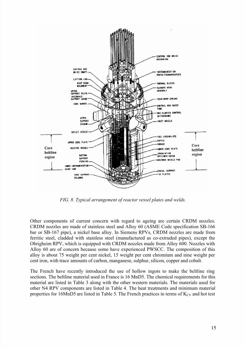
The part of the vessel of primary concern with regard to age related degradation is the core beltline — the region of shell material directly surrounding the effective height of the fuelelement assemblies plus an additional volume of shell material, both below and above theactive core, with an end-of-life fluence of more than 1021 n/m2 (E >1 MeV) [6]. It is typicallylocated in the intermediate and lower shells (Fig. 8). The low alloy steels making up the
beltline are subject to irradiation embrittlement that can lead to loss of fracture toughness.When early vessels were designed and constructed, only limited data existed about changes inmaterial properties caused by radiation damage. Now we know that the susceptibility of RPVsteel is strongly affected by the presence of copper, nickel and phosphorus. Because operatingvessels fabricated before 1972 contain relatively high levels of impurity copper and
phosphorous, irradiation damage becomes a major consideration for their continued operation.
13

7/17/2019 IAEA 1556 Assessment and management of ageing of major nuclear power plant components important to safety …
http://slidepdf.com/reader/full/iaea-1556-assessment-and-management-of-ageing-of-major-nuclear-power-plant 24/215
T A B L E
3 .
C H E M I C A L R E Q U I R E
M E N T S ( H E A T A N A L Y S I S
) M A I N
F E R R I T I C
M A T E R
I A L S F O R
R E A C T O R C O M
P O N E N T S I N
W E S T E R N C O U N T R I E
S
D e s i g
n a t i o n
E l e m e n t s ( W e i g h t % )
C
S i
M n
P m a x
S m a x
C r
M o
N
i
V m a x
C u m a x
A l
S n
N 2
A s
A S T M
A 3 0 2 B
0 . 2 5
0 . 1 5
0 . 3 0
1 . 1 5 1 . 5 0
0 . 0 3 5
0 . 0 4 0
0 . 4 5
0 . 6 0
A S T M
A 3 3 6 , C o d e C a s e 1 2 3 6
0 . 1 9
0 . 2 5
0 . 1 5
0 . 3 5
1 . 1 0 1 . 3 0
0 . 0 3 5
0 . 0 3 5
0 . 3 5
0 . 5 0
0 . 6 0
0
. 4 0
0
. 5 0
A S M E A 5 0 8 c l 2 ( 1 9 7 1 )
0 . 2 7
0 . 1 5
0 . 3 5
0 . 5 0 0 . 9 0
0 . 0 2 5
0 . 0 2 5
0 . 2 5
0 . 4 5
0 . 5 5
0 . 7 0
0
. 5 0
0
. 9 0
0 . 0 5
A S M E A 5 3 3 g r B ( 1 9 7 1 )
0 . 2 5
0 . 1 5
0 . 3 0
1 . 1 5 1 . 5 0
0 . 0 3 5
0 . 0 4 0
0 . 4 5
0 . 6 0
0
. 4 0
0
. 7 0
A S M E A 5 0 8 c l 2 ( 1 9 8 9 ) ( 1 )
0 . 2 7
0 . 1 5
0 . 4 0
0 . 5 0 1 . 0 0
0 . . 0 1 5
0 . 0 1 5
0 . 2 5
0 . 4 5
0 . 5 5
0 . 7 0
0
. 5 0
1
. 0 0
0 . 0 5
0 . 1 5
A S M E A 5 0 8 c l 3 ( 1 9 8 9 ) ( 1 )
0 . 2 5
0 . 1 5
0 . 4 0
1 . 2 0 1 . 5 0
0 . 0 1 5
0 . 0 1 5
0 . 2 5
0 . 4 5
0 . 6 0
0
. 4 0
1
. 0 0
0 . 0 5
A S M E A 5 3 3 g r B ( 1 9 8 9 )
0 . 2 5
0 . 1 5
0 . 4 0
1 . 1 5 1 . 5 0
0 . 0 3 5
0 . 0 4 0
0 . 4 5
0 . 6 0
0
. 4 0
0
. 7 0
1 6 M n D 5 R C C - M 2 1 1 1 ( 2 )
0 . 2 2
0 . 1 0
0 . 3 0
1 . 1 5 1 . 6 0
0 . 0 2
0 . 0 1 2
0 . 2 5
0 . 4 3
0 . 5 7
0
. 5 0
0
. 8 0
0 . 0 1
0 . 2 0
0 . 0 4 0
1 8 M n D 5 R C C - M 2 1 1 2 ( 1 9 8 8 )
0 . 2 0
0 . 1 0
0 . 3 0
1 . 1 5 1 . 5 5
0 . 0 1 5
0 . 0 1 2
0 . 2 5
0 . 4 5
0 . 5 5
0
. 5 0
0
. 8 0
0 . 0 1
0 . 2 0
0 . 0 4 0
2 0 M n M o N i 5 5 ( 1 9 8 3 , 1 9 9 0 ) ( 3 ) ( 4 )
0 . 1 7
0 . 2 3
0 . 1 5
0 . 3 0
1 . 2 0 1 . 5 0
0 . 0 1 2
0 . 0 0 8
0 . 2 0
0 . 4 0
0 . 5 5
0
. 5 0
0
. 8 0
0 . 0 2
0 . 1 2 ( 5 )
0 . 0 1 0
0 . 0 4 0
0 . 0 1 1
0 . 0 1 3
0 . 0 3 6
2 2 N i M o C r 3 7 ( 1 9 9 1 ) ( 6 )
0 . 1 7
0 . 2 3
0 . 1 5
0 . 3 5
0 . 5 0 1 . 0 0
0 . 0 1 2
0 . 0 0 8
0 . 2 5
0 . 5 0
0 . 6 0
0
. 6 0
1
. 2 0 ( 7 )
0 . 0 2
0 . 1 2 ( 5 )
0 . 0 1 0
0 . 0 5 0
0 . 0 1 1
0 . 0 1 3
0 . 0 3 6
( 1 ) S u p p l e m e n t a r y R e q u i r e m e n t S 9 . 1 ( 2 ) a n d S 9
. 2 f o r A 5 0 8 c l 2 a n d 5 0 8 c l 3 .
( 2 ) F o r g i n g s f o r r e a c t o r s h e l l s o u t s i d e c o r e r e g i o n . R e s t r i c t i o n s f o r C o r e R e g i o n
( R C C - M 2 1 1 1 ) : S < 0 . 0 0 8 , P < 0 . 0 0 8 , C u < 0 . 0 8 .
( 3 ) V d T
Ü V M a t e r i a l S p e c i f i c a t i o n 4 0 1 , I s s u e 1 9 8 3 .
( 4 ) K T A 3 2 0 1 . 1 A p p e n d i x A , I s s u e 6 / 9 0 .
( 5 ) C u - C o n t e n t f o r R P V ( C o r e R e g i o n ) s h a l l b e < 0 . 1 0 % .
( 6 ) A c c o r d i n g S i e m e n s / K W U u n d e r c o n s i d e r a t i o n o f S R 1 0 ( M P a S t u t t g a
r t ) .
( 7 ) F o r f l a n g e s a n d t u b e s h e e t s
t h e N i - c o n t e n t s h a l l b e < 1 . 4 0 % .
14
7/17/2019 IAEA 1556 Assessment and management of ageing of major nuclear power plant components important to safety …
http://slidepdf.com/reader/full/iaea-1556-assessment-and-management-of-ageing-of-major-nuclear-power-plant 25/215
FIG. 8. Typical arrangement of reactor vessel plates and welds.
Other components of current concern with regard to ageing are certain CRDM nozzles.CRDM nozzles are made of stainless steel and Alloy 60 (ASME Code specification SB-166
bar or SB-167 pipe), a nickel base alloy. In Siemens RPVs, CRDM nozzles are made fromferritic steel, cladded with stainless steel (manufactured as co-extruded pipes), except the
Obrigheim RPV, which is equipped with CRDM nozzles made from Alloy 600. Nozzles withAlloy 60 are of concern because some have experienced PWSCC. The composition of thisalloy is about 75 weight per cent nickel, 15 weight per cent chromium and nine weight percent iron, with trace amounts of carbon, manganese, sulphur, silicon, copper and cobalt.
The French have recently introduced the use of hollow ingots to make the beltline ringsections. The beltline material used in France is 16 MnD5. The chemical requirements for thismaterial are listed in Table 3 along with the other western materials. The materials used forother N4 RPV components are listed in Table 4. The heat treatments and minimum material
properties for 16MnD5 are listed in Table 5. The French practices in terms of K CV and hot test
15

7/17/2019 IAEA 1556 Assessment and management of ageing of major nuclear power plant components important to safety …
http://slidepdf.com/reader/full/iaea-1556-assessment-and-management-of-ageing-of-major-nuclear-power-plant 26/215
T A B L
E 4 . M A T E R I A L S S P E C I F I E D F O R P W R V E S S E L C O M P O N E N T S
U . S . P
l a n t s :
C l o s u r e
H e a d
D o m e
C l o s u r e
H e a d
F l a n g e
L i f t i n g
L u g s
S h r o u d
S u p p o r t
R i n g
C l o s u r e
H e a d
S t u d
A s s e m b l y
V e s s e l
F l a n g e
S h e l l s
B o t t o m
H e a d
N o z z l e s
C R D M
H o u s i n g s
S t a i n l e s s
S t e e l
C l a d d i n g
L e a k a g e
M o n i t o r -
i n g T u b e s
C o r e
S u p p o r t
P a d s
( L u g s )
I n s t r u -
m e n t a -
t i o n T u b e s /
P e n t r a -
t i o n s
R e f u e l l i n
g
S e a l
L e d g e
S A 3 0 2
G R B
S A 3 3 6
S A 3 0 2
G R B
S A 2 1 2
G R B
S A 3 2 0
L 4 3
S A 3 3 6
S A 3 0 2
G R B
S A 3 0 2
G R B
S A 3 0 2
G R B
S A 1 8 2
T Y P E S
3 0 4 , 3 1 6
T Y P E
3 0 8 L ,
3 0 9 L
S A 3 1 2
T Y P E
3 1 6
S B 1 6 6
S B 1 6 6
S A 2 1 2
G R B
S A 5 3 3
G R
B
C l a s s
1
S A 5 0 8
C l a s s 2
S A 5 0 8
C l a s s 3
S A 5 3 3
G R B
C l a s s 1
S A 5 1 6
G R 7 0
S A 5 4 0
B 2 3 , B 2 4
S A 5 0 8
S A 5 3 3
G R B
C l a s s 1
S A 5 3 3
G R B
C l a s s 1
S A 5 3 3
G R B
C l a s s 1
S B 1 6 6
T Y P E
3 0 4
S B 1 6 6
S B 1 6 7
S B 1 6 7
S A 5 1 6
G R 7 0
S A 3 2 0
L 4 3 C l a s s 3
S A 3 3 6
S A 3 3 6
S B 1 6 7
S A 5 3 3
S A 5 0 8
C l a s s 2
S A 5 0 8
C l a s s 3
S A 5 0 8
C l a s s 2
S A 5 0 8
C l a s s 3
F r e n c h
4 - l o o p N 4 P l a n t s :
S h e l l s ,
f l a n g e s , h e a d s , n o z z l e s
1 6 M n D 5
S a f e e n
d s , A d a p t e r f l a n g e s
Z 2 C N D 1 8 - 1 2
A d a p t e r s l e e v e s , i n s t r u m e n t a t i o n p e n e t r a t i o n s
N C 1 5 F e / N C 3 0 F e
S t u d s , n u t s , w a s h e r s
4 0 N C D V 7 - 0 3
I n t e r n a l s u p p o r t s
N C 1 5 F e
16

7/17/2019 IAEA 1556 Assessment and management of ageing of major nuclear power plant components important to safety …
http://slidepdf.com/reader/full/iaea-1556-assessment-and-management-of-ageing-of-major-nuclear-power-plant 27/215
TABLE 5. HEAT TREATMENTS AND MINIMUM MATERIAL PROPERTIES FOR16MND5
Austenisation 850-925°C
Tempering 635-668°C
Stress relieve 600-630°C
Rp 0.2% at 20°C > 400 MPa
Rm at 20°C 550-670 MPa
A% at 20°C > 20
Rp 0.2% at 350°C > 300 MPa
Charpy energy in J at 0°C TL: Ind. > 40(1) Mean > 56(2)
L: Ind. > 56Mean > 72
at -20°C TL: Ind. > 28Mean > 40
L: Ind. > 40Mean > 56
at +20°C TL: Ind. > 72
L: Ind. > 88
(1) Measurement is from one individual specimen.(2) Measurements from three specimens which are averaged.
requirements should be noted. As a general rule, material with a tensile strength at roomtemperature above 70 MPa cannot be used for pressure boundaries. The other western RPVsare designed with a minimum tensile strength of 350 MPa (50 Ksi).
Fabrication practice
Fabrication of RPVs has also been an evolving technology, and later vessels were fabricated
using knowledge gained from the surveillance programmes and more modern methods suchas the use of large forgings to reduce the number of welds in the beltline [6, 9].
Most RPVs in the USA were fabricated by either Combustion Engineering, Chicago Bridgeand Iron, or Babcock and Wilcox. Westinghouse did not fabricate vessels but had themfabricated at another shop. Some vessels were fabricated in Europe by Rotterdam DrydockCompany and by Creusot-Loire. In some cases, vessels were constructed by more than onefabricator because of scheduling problems in the shops.
17

7/17/2019 IAEA 1556 Assessment and management of ageing of major nuclear power plant components important to safety …
http://slidepdf.com/reader/full/iaea-1556-assessment-and-management-of-ageing-of-major-nuclear-power-plant 28/215
Fig. 9. Fabrication configuration of PWR beltline shells.
Large vessels are fabricated by two methods. In the first method, rolled and welded plates areused to form separate steel courses. Such a vessel has both longitudinal and circumferentialweld seams (Fig. 9a). In some older vessels (before 1972), the longitudinal welds are of
particular concern with regard to vessel integrity because they contain high levels of copperand phosphorous. In the second method, large ring forgings are used (Fig. 9b). This methodimproves component reliability because of the lack of longitudinal welds. Weld seams arelocated to avoid intersection with nozzle penetration weldments. Weldments within the
beltline region were minimized once research showed that weld metal could be more sensitiveto neutron radiation than base material. In general, parts of the longitudinal shell course weldsare within the beltline region when the RPV is fabricated using plate material.
18

7/17/2019 IAEA 1556 Assessment and management of ageing of major nuclear power plant components important to safety …
http://slidepdf.com/reader/full/iaea-1556-assessment-and-management-of-ageing-of-major-nuclear-power-plant 29/215
At least one circumferential weld is near, or marginally within, the beltline region when the
RPVs are fabricated from either plates or ring forgings. Recently, NSSS vendors are
designing the RPV such that the beltline region does not contain any weldments. This is
accomplished by utilizing very large ring forgings to fabricate the shell course.
Western RPV heads may be fabricated by welding a central dished plate to multiple toroidal
plates, sometimes called "orange peel" sections, forming a hemisphere. The lower head iswelded to the lower shell course while the top head is joined to the shell course by a flanged
and bolted joint. However, the modern French and German RPVs do not have welds in the
heads except for the circumferential weld which connects the head to the flange (top) or shell
(bottom).
The interior surfaces of the steel vessel, closure head and flange area are typically clad with
stainless steel, usually Type 308 or 309. Cladding was used to prevent general corrosion by
borated coolant and to minimize the buildup of corrosion products in the reactor coolant
system. The cladding was applied in one or two layers by multiple-wire, single-wire, strip-
cladding, or resistance welding processes. Some vessels have areas of Alloy 82 or 182 weld
cladding where Alloy 600 components were welded to the vessel.
During the fabrication of some RPVs it was discovered that small cracks were present in the
base metal beneath the cladding of the steel. The first incident of underclad cracking was
discovered in the early 1970s in Europe and later in the USA. This cracking was defined as
"reheat cracking" because the cracks appeared after the final stress relief heat treatment of the
RPVs. Reheat cracking was limited to RPVs fabricated from A508 Class 2 forging steel or the
equivalent European grades. Reheat cracking only occurred when the cladding was applied
utilizing a high heat input welding procedure. During the cladding process, grain coarsing
occurred due to the high heat input of the welding procedure, thus weakening the underclad
grain boundaries. Then the subsequent post-weld stress relief heat treatment at elevated
temperature resulted in decohension of the grain boundaries, e.g. small cracking occurred.Underclad reheat cracks are approximately 2 to 3 mm in depth and can be detected during the
preservice NDE by using straight beam transducers. However, it is virtually impossible to size
these cracks with NDT. Reheat cracking is, for the most part, confined to the cylindrical
portion of the RPV. The beltline region can contain many millions of small reheat cracks.
The second incident of underclad cracking occurred in the late 1970s in Europe followed by
discovery of cracks in the USA. The second incident of underclad cracking was identified as
"cold cracking". Cold cracking only occurred during the cladding process of the RPV when
the second layer of cladding was applied without preheat. Cold cracking was, for the most
part, limited to the highly constrained nozzle regions in the RPV. The mechanism for cold
cracking was hydrogen diffusion into the base metal during the application of the second layerof cladding The cracking occurred following cooldown of the component at locations where
there was hydrogen and a high strain due to the RPV nozzle configuration The size of the cold
crack beneath the cladding is of the order of 6 to 8 mm and these cracks are readily
discovered during NDE. Unlike reheat cracking, the cracks that occurred due to cold cracking
were removed by grinding prior to the vessel going into service. All RPV steels are
susceptible to cold cracking if the cladding is applied without preheat in regions of high
constraint. It is unlikely that cold cracking will occur at the beltline region of the RPV.
The USNRC reviewed the issue of reheat cracking and concluded that it was not a safety issue
[10]. However, the USNRC also prohibited the use in USA of high heat input welding
procedures for cladding of RPVs. To date there has not been any growth of the reheat cracksdetected during the in-service inspections (ISIs). Cold cracking is not considered to be a
19

7/17/2019 IAEA 1556 Assessment and management of ageing of major nuclear power plant components important to safety …
http://slidepdf.com/reader/full/iaea-1556-assessment-and-management-of-ageing-of-major-nuclear-power-plant 30/215
significant issue because, for the most part, the cold cracks were removed prior to plantstartup. Also any cold cracks that were inadvertently missed prior to startup would have beenreadily detected during the ISIs. Whitman et al. [11], Griesbach and Server [12], Griesbach[6] describe fabrication methods in detail, the Electric Power Research Institute (EPRI) [13]gives additional references. Kanninen and Chell [14] discussed the effect of the cladding onvessel integrity. Radiation embrittlement of beltline materials and the computer database
containing data on beltline materials used in US reactors are covered in Ref [9].
Welding
The welding processes used were mostly submerged-arc and shielded-metal-arc. Before theearly 1970s, copper-coated weld wire was used to improve the electrical contact in thewelding process and to reduce corrosion during storage of the weld wire hence the generationof hydrogen. When it was discovered that copper and phosphorus increased the weldssensitivity to radiation embrittlement, RPV fabricators imposed strict limits on the percentageof copper and phosphorus in the welds as well as in plates [6, 11, 12]. The use of coppercoated weld wire was eliminated due to the strict limits on the percentage of copper in the
weld. The weld wire or stick electrodes were kept in storage in plastic bags and/or lowtemperature furnaces to eliminate the formation of moisture on the weld wire and electrodes.
For the circumferential welds, many beads of weld material and consequently a large volumeof weld wire are needed. This becomes important when determining the properties of eachindividual weld in the beltline for sensitivity to neutron irradiation. For example, thechemistry of the weld (copper and nickel content) may vary through the thickness and aroundthe circumference because of variations in the weld wire used in fabrication. Each weld in thevessel can be traced by the unique weld wire and flux lot combination used [9].
The sensitivity of welds to radiation can be inferred from the chemical composition. The
degree of embrittlement [shift in transition temperature or decrease in upper shelf energy(USE)] is determined as a function of the chemical composition and the level of neutronexposure. Copper, nickel and possible phosphorus content in the weld are the most importantelements from the standpoint of radiation damage. The embrittlement of high copper and highnickel welds plays a key role in the assessment of the significance of pressurized thermalshock (PTS) [9].
20

7/17/2019 IAEA 1556 Assessment and management of ageing of major nuclear power plant components important to safety …
http://slidepdf.com/reader/full/iaea-1556-assessment-and-management-of-ageing-of-major-nuclear-power-plant 31/215
T A B L E 6 . N O R M A L C H E M I C A L
C O M P O S I T I O N O F W W E R R
E A C T O R P R E S S U R E V E S S E L M A T E R I A L S ( W E I G H T %
)
M A T E R I A L
C
M n
S i
P
S
C r
N i
M o
V
W
W E R - 4 4 0
1 5
K h 2 M F A
0 . 1 3
0 . 1 8
0 . 3 0
0 . 6 0
0 . 1 7
0 . 3 7
m a x
0 . 0 2 5
m a x
0 . 0 2 5
2 . 5 0
3 . 0 0
m a x
0 . 4 0
0 . 6 0
0 . 8 0
0 . 2 5
0 . 3 5
S u b m e r g e d
a r c
w e l d S v - 1 0 K h M F T
+
A N - 4 2
0 . 0 4 0
. 1 2
0 . 6 0
1 . 3 0
0 . 2 0
0 . 6 0
m a x .
0 . 0 4 2
m a x
0 . 0 3 5
1 . 2 0
1 . 8 0
m a x
0 . 3 0
0 . 3 5 0 . 7 0
0 . 1 0
0 . 3 5
S u b m e r g e d
a r c
w e l d S v - 1 0 K h M F T
+
A N - 4 2 M
0 . 0 4
0 . 1 2
0 . 6 0
1 . 3 0
0 . 2 0
0 . 6 0
m a x
0 . 0 1 2
m a x
0 . 0 1 5
1 . 2 0
1 . 8 0
m a x
0 . 3 0
0 . 3 5 0 . 7 0
0 . 1 0
0 . 3 5
E l e c t r o s l a g w e l d
S v - 1 3 K h 2 M F T
+
O F - 6
0 . 1 1
0 . 1 6
0 . 4 0
0 . 7 0
0 . 1 7
0 . 3 5
m a x
0 . 0 3 0
m a x
0 . 0 3 0
1 . 4 0
2 . 5 0
-
0 . 4 0 0 . 8 0
0 . 1 7
0 . 3 7
T A B L E 7 . R E Q U I R E M E N T S F O R
A A R P V S T E E L / W E L D Q U A
L I T Y ( M A X I M U M A L L O W A B L E C O N T E N T , M A S S % )
E l e m
e n t
P
S
C
u
A s
S b
S n
P + S b + S n
C o
A A
-
q u a l i t y
f o
r
b e l t l i n e
m a t e r i a l s
0 . 0 1 2
0 . 0 1 5
0 . 0 8
0 . 0 1 0
0 . 0 0 5
0 . 0 0 5
0 . 0 1 5
0 . 0 2 0
21

7/17/2019 IAEA 1556 Assessment and management of ageing of major nuclear power plant components important to safety …
http://slidepdf.com/reader/full/iaea-1556-assessment-and-management-of-ageing-of-major-nuclear-power-plant 32/215
T A
B L E 8 A . G U A R A N T E E D M E
C H A N I C A L P R O P E R T I E S O
F W W E R V E S S E L M A T E R I A
L S *
2 0 ° C
3 5 0 ° C
T k 0
( 1 )
R T N D T
( 2 )
R p 0 . 2
R m
A 5
Z
R p 0 . 2
R m
A 5
Z
M A T E R I A L
[ M p a ]
[ M p a ]
[ % ]
[ % ]
[ M p a ]
[ M p a ]
[ % ]
[ % ]
[ O C ]
1 5 K h 2 M F A
- b a s e m e t a l
4 3 1
5 1 9
1 4
5 0
3 9 2
4 9 0
1 4
5 0
0 ( 1 )
A / S w e l d m e t a l
3 9 2
5 3 9
1 4
5 0
3 7 3
4 9 0
1 2
4 5
2 0 ( 1 )
* R p 0 . 2
i s t h e 0 . 2 p e r c e n t o f f s e t y i e l d s t r e n g t h , R m i s t h e u l t i m a t e t e n s i l e s t r e
n g t h , Z i s t h e p e r c e n t r e d u c t i o n i n a r e a a t f a i l u r e , a n d T k 0 i s t h e i n i t i a l d u c t i l e - b r i t t l e t r a n s i t i o n
t e m p e r a t u r e .
22

7/17/2019 IAEA 1556 Assessment and management of ageing of major nuclear power plant components important to safety …
http://slidepdf.com/reader/full/iaea-1556-assessment-and-management-of-ageing-of-major-nuclear-power-plant 33/215
T A
B L E 8 B .
L I S T O F A B B R
E V I A T I O N S U S E D I N W W E
R M A T E R I A L S
C h e m i c a l e l e m e n t s
A
h i g h q u a l i t y
A A
v e r y h i g h q
u a l i t y / p u r i t y
U
i m p r o v e d
B
n i o b i u m
F
V a n a d i u m
G
m a n g a n e s e
K h
C h r o m i u m
M
m o l y b d e n u m
N
N i c k e l
S v
w e l d i n g w i r e
T
T i t a n i u m
B e g i n n i n g o f t h e d e s i g n a t i o n :
0
l o w e r t h a n 0 . 1 m a s s % C
0 8
m e a n v a l u e 0 . 0 8 % C
1 5
m e a n v a l u e 0 . 1 5 % C
C e n t r e o f t h e d e s i g n a t i o n :
K h 2
m e a n v a l u e 2 % C r
M
l o w e r t h a n
1 % M o
23

7/17/2019 IAEA 1556 Assessment and management of ageing of major nuclear power plant components important to safety …
http://slidepdf.com/reader/full/iaea-1556-assessment-and-management-of-ageing-of-major-nuclear-power-plant 34/215
2.2.2. WWER pressure vessels
The WWER pressure vessel materials are listed in Table 2b. The normal chemicalcompositions of the various WWER materials are listed in Table 6, the allowable impuritiesin the beltline region are listed in Table 7 and the guaranteed mechanical properties are listedin Table 8a. Table 8b provides list of abbreviations used in WWER materials. As indicated by
the information in these tables, the WWER pressure vessel materials are basically differentfrom the western RPV materials. The Type 15Kh2MFA(A) material used for the WWER-440 pressure vessels contains 0.25 to 0.35 weight per cent vanadium and very little nickel(maximum of 0.40 weight per cent). The Type 15Kh2NMFA(A) material used for theWWER-1000 pressure vessels contains 1.0 to 1.5 weight per cent nickel and almost novanadium. Material with vanadium alloying was first used in the Soviet naval RPVs becausethe vanadium carbides make the material relatively resistant to thermal ageing, fine grained(tempered banite) and strong. However, the Type 15Kh2MFA(A) material is harder to weldthan nickel steels and requires very high preheating to avoid hot cracking. This became moreof a problem for the large WWER-1000 pressure vessels and a material with nickel ratherthan vanadium alloying was chosen. The influence of vanadium on the susceptibility of those
materials to radiation embrittlement was shown to be negligible.
Not all the WWER pressure vessels were covered by austenitic stainless steel cladding ontheir whole inner surface: only approximately half of the WWER-440/V-230 pressure vesselswere clad. However, all of the WWER-440/V-213 and WWER-1000 pressure vessels werecovered on the whole inner surface. The cladding was made by automatic strip welding underflux with two layers — the first layer is made of a Type 25 chromium/13 nickel unstabilizedaustenitic material (Sv 07Kh25N13), and the second layer is at least three beads made of Type18 chromium/10 nickel stabilized austenitic stainless steel (Sv 08Khl8N10G2B) to achieve arequired total thickness of cladding equal to ~ 8 mm. Therefore, all the austenitic steels whichare in contact with water coolant are stabilized. The stabilized austenitic stainless steels
contain an alloying element (usually titanium) which forms stable gain boundary carbides.This prevents chromium depletion along the grain boundaries and makes the material immuneto stress corrosion cracking. Unstabilized material was used for the first layer because thethermal expansion coefficient of that material is closer to the thermal expansion coefficient ofthe low-alloy pressure vessel material.
The WWER vessel head contains penetrations with nozzles. The nozzles are welded to thevessel head from inside (buttering) and are protected by stainless steel sleeving (0Kh18N10T).
The WWER quality control and QA procedures are applied during manufacture, assembly andinstallation of the reactor in accordance with applicable standards. The required quality is
ensured by:• design by analysis,
• quality control of base and weld materials used,
• quality control during manufacture,
• acceptance testing prior to installation at the site.
Testing is performed using ultrasonic, radiographic, dye-penetrant and magnetic particlemethods and includes hydrotests, if applicable. RPVs made in the Czech Republic were alsomonitored by acoustic emissions during the pressure hydrotests at the manufacturing site(ŠKODA), in Plzeň.
24

7/17/2019 IAEA 1556 Assessment and management of ageing of major nuclear power plant components important to safety …
http://slidepdf.com/reader/full/iaea-1556-assessment-and-management-of-ageing-of-major-nuclear-power-plant 35/215
3. DESIGN BASIS: CODES, REGULATIONS AND GUIDES FOR
REACTOR PRESSURE VESSELS
The load restrictions on as-fabricated RPVs in various national standards and codes aregenerally based on Section III of the ASME Boiler and Pressure Vessel Code [7]. Theobjective of designing and performing a stress analysis under the rules of Section III to the
ASME Boiler and Pressure Vessel Code is to afford protection of life and property againstductile and brittle RPV failure. The ASME Section III requirements are discussed in the nextsection. Some important differences exist in the RPV design requirements of certain othercountries (e g Germany, France and Russia) and these differences are discussed in Sections3.3, 3.4 and 3.5.
3.1. DESIGN BASIS IN ASME SECTION III
The reactor vessel has been designated as Safety Class 1, which requires more detailedanalyses than Class 2 or 3 components. The rules for Class 1 vessel design are contained inArticle NB-3000 [7], which is divided into three sub-articles.
(a) NB-3100, General design rules
(b) NB-3200, Design by analysis
(c) NB-3300, Vessel design
Sub-article NB-3100 deals with loading conditions specified by the owner (or his agent) in theform of an equipment specification. The specification identifies the design conditions andoperating conditions (normal conditions, upset conditions, emergency conditions, faultedconditions and testing conditions).
Sub-article NB-3200 deals with the stresses and stress limits which must be considered for theanalysis of the component. The methods of analysis and stress limits depend upon thecategory of loading conditions, i.e. the requirement for normal conditions are considerablymore stringent than those for faulted conditions.
Sub-article NB-3300 gives special requirements that have to be met by Class 1 vessels. Thisarticle gives tentative thickness requirements for shells, reinforcement requirements fornozzles and recommendations for welding nozzles, for example.
3.1.1. Transient specification
It is impossible to determine accurately the stresses in a component without a correct
description of the loads applied to that component. The loads themselves are divided into two broad categories static and dynamic, the dynamic loads arising primarily from seismicconditions. The distinction between static and dynamic loads is based primarily on thecomparison of the time span of the load variation to the response time of the structure.
The operating conditions themselves are divided into five categories depending on the seventyof the transient and the number of occurrences.
(a) Normal conditions
(b) Upset conditions
(c) Emergency conditions
25

7/17/2019 IAEA 1556 Assessment and management of ageing of major nuclear power plant components important to safety …
http://slidepdf.com/reader/full/iaea-1556-assessment-and-management-of-ageing-of-major-nuclear-power-plant 36/215
(d) Faulted conditions
(e) Testing conditions.
Normal conditions are those which exist during normal running of the plant. Upset conditionsare deviations from the normal conditions but are anticipated to occur often enough that
provisions for them must be made in the analysis. These transients are those that do not result
in forced outage, or if forced outage occurs, the restoration of power does not requiremechanical repair. Emergency conditions are deviations from normal which require shutdownand may require repair and must be considered in order to assure no gross loss of structuralintegrity. Faulted conditions are deviations from normal, are extremely low probability, butmay result in loss of integrity and operability of the system. Testing conditions are pressureoverload tests, or other tests on the primary system.
For a PWR, the definitions of all operating transients are contained in the equipmentspecifications and are designed to represent the conditions under which a specific plant wouldoperate. The interrelationship of the many groups within an organization needed to producesuch a document is shown in Fig. 10. A listing of the transients, categories and number of
occurrences contained in a typical specification is shown in Table 9.3.1.2. Analysis of normal and upset conditions
Description of stress categories
The rules for design of Class 1 vessels make use of both realistic and accurate analysistechniques and failure criteria and therefore have relaxed overly restrictive safety factors usedin the past. The calculated value of stress means little until it is associated with a location anddistribution in the structure and with the type of loading which produced it. Different types ofstress have different degrees of significance and must, therefore, be assigned differentallowable values. For example, the average hoop stress through the thickness of the wall of a
vessel due to internal pressure must be held to a lower value than the stress at the root of anotch in the wall.
Fig. 10. Development of design transients.
26

7/17/2019 IAEA 1556 Assessment and management of ageing of major nuclear power plant components important to safety …
http://slidepdf.com/reader/full/iaea-1556-assessment-and-management-of-ageing-of-major-nuclear-power-plant 37/215
TABLE 9. TYPE OF TRANSIENT, NUMBER OF OCCURRENCES, AND TRANSIENTCLASSIFICATION IN A TYPICAL PWR DESIGN SPECIFICATION
Title Occurrences Classification
Plant Heatup at 55°C (100°F)/Hr. 200 Normal
Plant Cooldown at 55°C (100°F)/Hr. 200 NormalPlant Loading at 5% of Full Power per Minute 18,300 Normal
Plant Unloading at 5% of Full Power per Minute 18,300 Normal
Step Load Increase of 10% of Full Power 2,000 Normal
Step Load Decrease of 10% of Full Power 2,000 Normal
large Step Load Decrease (with Steam Dump) 200 Normal
Steady State Fluctuations Infinite Normal
Loss of Load (without Immediate Turbine or Reactor Trip) 80 UpsetLoss of Power (Blackout with Natural Circulation inReactor Coolant System)
40 Upset
Loss of Flow (Partial Loss of Flow-One Pump Only) 80 Upset
Reactor Trip from Full Power 400 Upset
Inadvertent Auxiliary Spray 10 Upset
Turbine Roll Test 10 Test
Primary Side Hydrostatic Test Before Startup at 3105 psig
(218.3 kg/cm2
)
5 Test
Primary Side Leak Test at 174.7 kg/cm2 (2485 psig) 50 Test
Steam Pipe Break 1 Faulted
Reactor Coolant Pipe Break 1 Faulted
Likewise, a thermal stress can often be allowed to reach a higher value than one which is produced by dead weight or pressure. Therefore, a new, set of design criteria were developedwhich shifted the emphasis away from the use of standard configurations and toward thedetailed analyses of stresses. The setting of allowable stress values required dividing stressesinto categories and assigning different allowable values to different groups of categories. Thefailure theory used here is the maximum shear stress theory which has been found appropriateto reactor vessel applications and has the advantage of simplicity. Other criteria like the Misescriteria could be used as well. The maximum shear stress calculated from the failure theorydefines stress intensities.
Different types of stress require different limits, and before establishing these limits, it wasnecessary to choose the stress categories to which limits should be applied. The categories andsub-categories chosen were as follows:
27

7/17/2019 IAEA 1556 Assessment and management of ageing of major nuclear power plant components important to safety …
http://slidepdf.com/reader/full/iaea-1556-assessment-and-management-of-ageing-of-major-nuclear-power-plant 38/215
A. Primary stress
(1) General primary membrane stress
(2) Local primary membrane stress
(3) Primary bending stress.
B. Secondary stress
C. Peak stress.
The chief characteristics of these stresses may be described as follows:
(a) Primary stress is a stress developed by the imposed loading which is necessary to satisfythe laws of equilibrium between external and internal forces and moments. The basiccharacteristic of a primary stress is that it is not self-limiting. If a primary stress exceedsthe yield strength of the material through the entire thickness, the prevention of failureis entirely dependent on the strain-hardening properties of the material.
(b) Secondary stress is a stress developed by the self-constraint of a structure. It mustsatisfy an internal strain pattern rather than equilibrium with an external load. The basiccharacteristic of a secondary stress is that it is self-limiting. These stresses are caused bythermal expansion or discontinuity conditions. The main concern with secondarystresses is that they may result in localized yielding or distortion.
(c) Peak stress is the highest stress in the region under consideration. The basiccharacteristic of a peak stress is that it causes no significant distortion and isobjectionable mostly as a possible source of fatigue failure.
Stress intensity limitsThe choice of the basic stress intensity limits for the stress categories described above wasaccomplished by the application of limit design theory tempered by some engineering
judgment and some conservative simplifications. The principles of limit design which wereused can be described briefly as follows.
The assumption is made of perfect plasticity with no strain-hardening. This means that anidealized stress-strain curve of the type shown in Fig. 11 is assumed. Allowable stresses,
based on perfect plasticity and limit design theory, may be considered as a floor below whicha vessel made of any sufficiently ductile material will be safe. The actual strain-hardening
properties of specific materials will give them larger or smaller margins above this floor.
In a structure as simple as a straight bar in tension, a load producing yield stress, Sy results in"collapse". If the bar is loaded in bending, collapse does not occur until the load has beenincreased by a factor known as the "shape factor" of the cross section; at that time a "plastichinge" is formed. The shape factor for a rectangular section in bending is 1.5. When the
primary stress in a rectangular section consists of a combination of bending and axial tension,the value of the limit load depends on the ratio between the tensile and bending loads. Figure12 shows the value of the maximum calculated stress at the outer fiber of a rectangular sectionwhich would be required to produce a plastic hinge, plotted against the average tensile stressacross the section, both values expressed as multiples of the yield stress, Sy. When the averagetensile stress, Pm is zero, the failure stress for bending is 1.5 Sy. When the average tensilestress is Sy no additional bending stress, P b, may be applied.
28

7/17/2019 IAEA 1556 Assessment and management of ageing of major nuclear power plant components important to safety …
http://slidepdf.com/reader/full/iaea-1556-assessment-and-management-of-ageing-of-major-nuclear-power-plant 39/215
Figure 12 was used to choose allowable values, in terms of the yield stress, for general primary membrane stress, Pm and primary membrane-plus-bending stress, Pm + P b. It may beseen that limiting Pm to (2/3) Sy and Pm + P b to Sy provides adequate safety. The safety factoris not constant for all combinations of tension and bending, but a design rule to provide auniform safety factor would be needlessly complicated.
In the study of allowable secondary stresses, a calculated elastic stress range equal to twicethe yield stress has a very special significance. It determines the borderline between loadswhich, when repetitively applied, allow the structure to "shake down" to elastic action andloads which produce plastic action each time they are applied; 2 Sy is the maximum value ofcalculated secondary elastic stress which will "shake down" to purely elastic action.
We have now shown how the allowable stresses for the first four stress categories listed in the previous section should be related to the yield strength of the RPV material. The last category, peak stress, is related only to fatigue and will be discussed later. With the exception of someof the special stress limits, the allowables in Codes are not expressed in terms of the yieldstrength, but rather as multiples of the tabulated value Sm which is the allowable for general
primary membrane stress. In assigning allowable stress values to a variety of materials withwidely varying ductilities and widely varying strain-hardening properties, the yield strengthalone is not a sufficient criterion. In order to prevent unsafe designs in materials with lowductility and in materials with high yield stress-to-tensile strength ratios, the Code has alwaysconsidered both the yield strength and the ultimate tensile strength in assigning allowablestresses. The stress intensity limits for the various categories given are such that the multiplesof yield strength described above are never exceeded.
Fig. 11. Idealized stress-strain relationship.
29
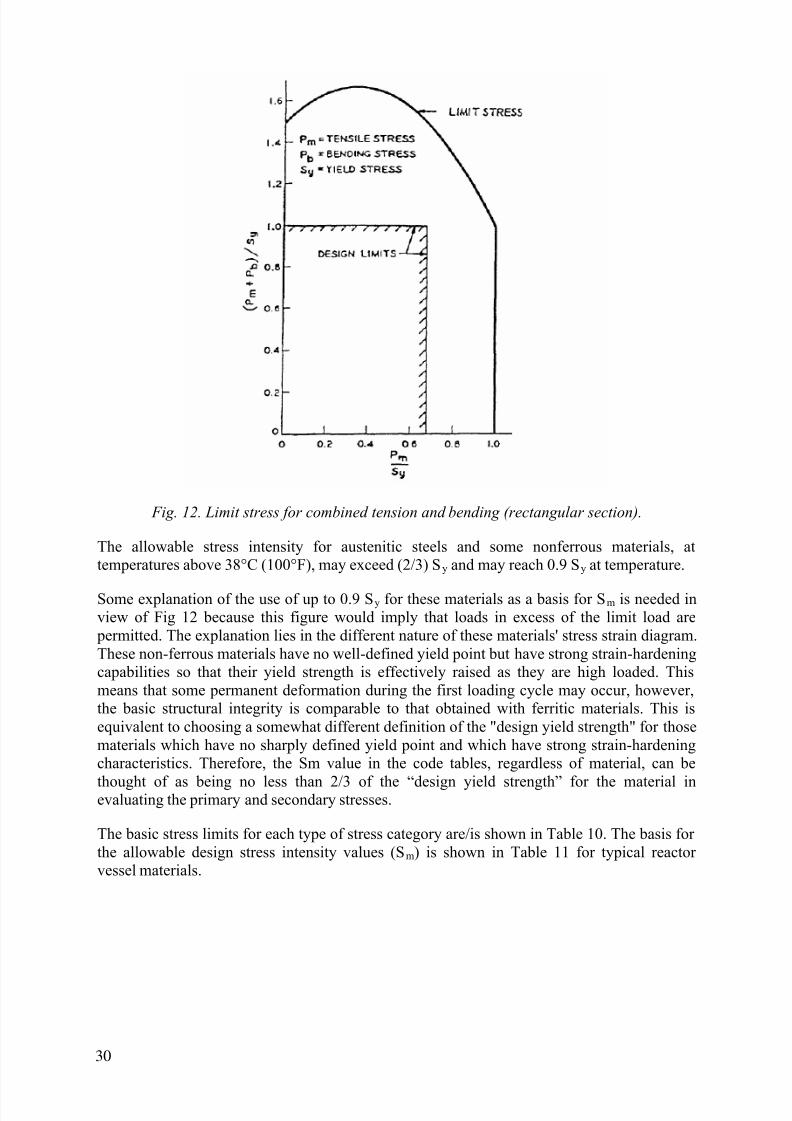
7/17/2019 IAEA 1556 Assessment and management of ageing of major nuclear power plant components important to safety …
http://slidepdf.com/reader/full/iaea-1556-assessment-and-management-of-ageing-of-major-nuclear-power-plant 40/215
Fig. 12. Limit stress for combined tension and bending (rectangular section).
The allowable stress intensity for austenitic steels and some nonferrous materials, attemperatures above 38°C (100°F), may exceed (2/3) Sy and may reach 0.9 Sy at temperature.
Some explanation of the use of up to 0.9 Sy for these materials as a basis for Sm is needed inview of Fig 12 because this figure would imply that loads in excess of the limit load are
permitted. The explanation lies in the different nature of these materials' stress strain diagram.These non-ferrous materials have no well-defined yield point but have strong strain-hardeningcapabilities so that their yield strength is effectively raised as they are high loaded. Thismeans that some permanent deformation during the first loading cycle may occur, however,the basic structural integrity is comparable to that obtained with ferritic materials. This isequivalent to choosing a somewhat different definition of the "design yield strength" for thosematerials which have no sharply defined yield point and which have strong strain-hardeningcharacteristics. Therefore, the Sm value in the code tables, regardless of material, can be
thought of as being no less than 2/3 of the “design yield strength” for the material inevaluating the primary and secondary stresses.
The basic stress limits for each type of stress category are/is shown in Table 10. The basis forthe allowable design stress intensity values (Sm) is shown in Table 11 for typical reactorvessel materials.
30

7/17/2019 IAEA 1556 Assessment and management of ageing of major nuclear power plant components important to safety …
http://slidepdf.com/reader/full/iaea-1556-assessment-and-management-of-ageing-of-major-nuclear-power-plant 41/215
TABLE 10. ASME SECTION III STRESS LIMITS AND POTENTIAL FAILURE MODEFOR EACH TYPE OF STRESS CATEGORY
TABLE 11. BASIS FOR THE ALLOWABLE DESIGN STRESS-INTENSITYVALUES (Sm) IN SECTION III OF THE ASME CODE
Fatigue evaluationThe last stress category to be examined is that of peak stresses. This category is only aconcern in fatigue. The ASME Code gives specific rules for fatigue strength reduction factorsand design curves for each type of material. For the component design to be acceptable, thecumulative usage factor at the end of life must be less than unity. Under some conditionsoutlined in the Code, a fatigue analysis is not necessary, however, conditions are then fairlyrestrictive.
Areas of the vessel analysed
The regions of the vessel which are examined in order to determine compliance with the
ASME Code are shown in Figs 13-17. They are the areas which have potentially the higheststresses.
31

7/17/2019 IAEA 1556 Assessment and management of ageing of major nuclear power plant components important to safety …
http://slidepdf.com/reader/full/iaea-1556-assessment-and-management-of-ageing-of-major-nuclear-power-plant 42/215
Stress analysis methods
Depending on the vendor, several different methods are used to determine the stresses incomponents. Two of the most popular are discontinuity analysis and finite element analysis asshown in Figs 18 and 19, respectively for the reactor vessel inlet nozzle.
Fig. 13. Regions of a RPV to be analysed in order to determine
compliance with the ASME Code.
Typical results of analysis for normal and upset conditions
For normal and upset conditions, Table 12 shows the maximum calculated primary stressintensities for the general membrane category and the local membrane plus bending category.
Note, the stresses are all below the allowables for both categories.
Table 13 shows the maximum range of primary plus secondary stress intensities comparedagainst the allowable limits; also the table shows the calculated usage factors in fatigue. Note,the Code requirements are satisfied in all cases.
32

7/17/2019 IAEA 1556 Assessment and management of ageing of major nuclear power plant components important to safety …
http://slidepdf.com/reader/full/iaea-1556-assessment-and-management-of-ageing-of-major-nuclear-power-plant 43/215
Fig. 14. Typical control rod housing and closure head flange, shell and studs locations to be
evaluated in an ASME stress analysis.
Fig. 15. Typical inlet and outlet nozzle locations to be analysed in order to determine
compliance with the ASME Code
33

7/17/2019 IAEA 1556 Assessment and management of ageing of major nuclear power plant components important to safety …
http://slidepdf.com/reader/full/iaea-1556-assessment-and-management-of-ageing-of-major-nuclear-power-plant 44/215
Fig. 16. A typical vessel wall transition and core barrel support pad locations to be analysed
in order to determine compliance with the ASME Code.
Fig. 17. Typical bottom head to shell juncture and bottom head instrument penetration
locations to be analysed in order to determine compliance with the ASME Code.
Fig. 18. Discontinuity analysis model of reactor vessel inlet nozzle.
34

7/17/2019 IAEA 1556 Assessment and management of ageing of major nuclear power plant components important to safety …
http://slidepdf.com/reader/full/iaea-1556-assessment-and-management-of-ageing-of-major-nuclear-power-plant 45/215
Fig. 19. Finite element analysis model of reactor vessel inlet nozzle.
TABLE 12. MAXIMUM CALCULATED PRIMARY STRESS INTENSITIES VERSUSASME SECTION III ALLOWABLE LIMITS
35

7/17/2019 IAEA 1556 Assessment and management of ageing of major nuclear power plant components important to safety …
http://slidepdf.com/reader/full/iaea-1556-assessment-and-management-of-ageing-of-major-nuclear-power-plant 46/215
TABLE 13. MAXIMUM RANGE OF PRIMARY PLUS SECONDARY STRESSINTENSITIES COMPARED AGAINST THE ALLOWABLE LIMITS INSECTION III OF THE ASME CODE
TABLE 14. ALLOWABLE STRESS INTENSITY LIMITS IN SECTION III OF THEASME CODE FOR EMERGENCY CONDITIONS
36

7/17/2019 IAEA 1556 Assessment and management of ageing of major nuclear power plant components important to safety …
http://slidepdf.com/reader/full/iaea-1556-assessment-and-management-of-ageing-of-major-nuclear-power-plant 47/215
TABLE 15. ALLOWABLE PRIMARY STRESS LIMITS FOR FAULTEDCONDITIONS IN SECTION III OF THE ASME CODE
System or(Subsystem)Analysis
ComponentsAnalysis
Stress Limits for Components Components Supports
Pm P1 or [Pm(orP1)+P b] Pm P1 or[Pm(orP1)+P b]
Test
Elastic Elastic Smallerof
2.4Sm&0.70Su
Smaller of3.6Sm&1.05Su
(4)
Larger of1.5Sm or1.2Sy (1)
Larger of2.25Sm or
1.8Sy (4, 2)
ElasticPlastic Larger of
0.70 Su orSy + 1/3(Su Sy)
(5)
Larger of0.70 Su orSy + 1/3(Sut Sy)
(5)
Sy (1)L2 (3, 5)
1.5 Sy (4, 2)
0.8LT
LimitAnalysis
0.9 L1 (3) 0.9 L1 (3)
L2 (5)
Su = Ultimate stress from engineering stress-strain curve at temperatureSut = Ultimate stress from true stress-strain curve at temperatureSm = Stress intensity from ASME Section III at temperatureLT = Test Load
(1) But not to exceed 0.70 Su
(2) But not to exceed 1.05 Su
(3) L1 and L2 = Lower bound limit load with an assumed yield point equal to 2.3. Sm and Sy (but not to exceed 0.70Su), respectively.(4) These limits are based on a bending shape factor of 1.5. For simple bending cases with different shape factors,the limits will be changed
proportionally.(5) When elastic system analysis is performed, the effect of component deformation on the dynamic systemresponse should be checked.
37

7/17/2019 IAEA 1556 Assessment and management of ageing of major nuclear power plant components important to safety …
http://slidepdf.com/reader/full/iaea-1556-assessment-and-management-of-ageing-of-major-nuclear-power-plant 48/215
TABLE 16. GOVERNING MECHANICAL LOAD STRESS VERSUS ALLOWABLEFAULT CONDITION LIMITS
3.1.3. Analysis of emergency and faulted conditions
Description of stress categories and analysis methods
For these types of operating conditions, the rate of occurrence is significantly less than normaland upset conditions and the primary concern is to prevent burst and gross distortion. For thisreason limits are only placed upon the general membrane category and the local membrane
plus primary bending category. Also, because inelastic analysis is often required, the stresslimits are considerably more detailed. The system analysis used to determine the loads whichact on the components is generally a dynamic analysis because of the nature of the events
postulated (earthquakes/air crashes). This system analysis is generally elastic and the systemdesign is modified by adding supports and stiffness to control structural resonance conditions.If significant inelastic response occurs within the component the original elastic systemanalysis requires modification. The stress intensity limits for emergency conditions are shownin Table 14. Depending upon the analysis method the applicable primary stress limits forfaulted conditions are given in Table 15.
38

7/17/2019 IAEA 1556 Assessment and management of ageing of major nuclear power plant components important to safety …
http://slidepdf.com/reader/full/iaea-1556-assessment-and-management-of-ageing-of-major-nuclear-power-plant 49/215
Typical results for faulted conditions
For the purposes of illustration, only the critical locations around the nozzles thought to becritical will be considered. The results of the analysis are shown in Table 16. In this tableDBE is defined to be the Design Basis Earthquake and DBA is the Design Basis Accident.
3.1.4. Analysis of test conditions
The major interest for this transient is to prevent burst or permanent distortion. In the general primary membrane stress category, the stress intensity is limited to 0.9 of the tensile yieldstrength (σy) in the primary membrane plus primary bending stress category, the stressintensity is limited to 1 35 σy. For the cold hydrotest transient the results of the analysis areshown in Table 17.
TABLE 17. MAXIMUM CALCULATED STRESS INTENSITIES DURING A COLDHYDRO TEST TRANSIENT COMPARED WITH THE ALLOWABLELIMITS IN SECTION III OF THE ASME CODE
3.1.5. Design and analysis against non-ductile failure (heatup and cooldown limit curves
for normal operation)
At the recommendation of the Pressure Vessel Research Committee, the ASME Boiler andPressure Vessel Code introduced criteria into Section III — Nuclear Power Plant Components
— to provide assurance against brittle failure. The criteria required the component materialsto satisfy certain fracture toughness requirements (NB-2330 of the Code). The criteria alsointroduced non-mandatory Appendix G, "Protection Against Non- Ductile Failure", into theASME Code [15]. Appendix G of Section III presents a procedure for obtaining the allowableloading for ferritic pressure-retaining materials in Class 1 components. The procedure is basedon the principles of linear elastic fracture mechanics (LEFM). Appendix G provides areference critical stress intensity factor (K I) curve as a function of temperature, a postulatedflaw and a K I expression.
39

7/17/2019 IAEA 1556 Assessment and management of ageing of major nuclear power plant components important to safety …
http://slidepdf.com/reader/full/iaea-1556-assessment-and-management-of-ageing-of-major-nuclear-power-plant 50/215
The basic premise of LEFM is that unstable propagation of an existing flaw will occur whenthe value of K I attains a critical value for the material designated as K IC. K IC is called thelinear elastic fracture toughness of the material. In the case of ferritic materials, it has beenfound that the fracture toughness properties are dependent on temperature and on the loadingrates imposed. Dynamic initiation fracture toughness obtained under fast or rapidly appliedloading rates is designated K Id. Further, in structural steels, a crack arrest fracture toughness is
obtained under conditions where a propagating flaw is arrested within a test specimen. Thecrack arrest toughness is designated K Ia. Appendix G to Section III presents a reference stressintensity factor [K IR ] as a function of temperature based on the lower bound of static K IC,
dynamic K Id and crack arrest K Ia fracture toughness values. The K IR vs. temperature curve isshown in Fig. 20. No available data points for western-type ferritic RPV material yet testedfor static, dynamic or arrest tests fall below the curve given. The value of K IR represents avery conservative assumption as to the critical stress intensity vs. temperature properties ofmaterials similar to those tested, as related to the measured nil-ductility temperature. TheCode (NB-2331a) identifies a reference nil-ductility transition temperature (RT NDT) to indexthe K IR curve to the temperature scale. The reference temperature RT NDT is defined (NB-2331) as the greater of the drop weight nil-ductility transition temperature or a temperature
33.3°C (60°F) less than the 68 J (50 ft-lb) [and 0.9 mm (35 mils) lateral expansiontemperature] as determined from Charpy specimens oriented normal (NB-2322.2) to therolling direction of the material (the T-L orientation). The requirements of Charpy tests at33.3°C (60°F) above the nil-ductility temperature serve to sort out nontypical materials and
provide assurance of adequate fracture toughness at “upper shelf” temperatures. In addition,the requirement of lateral expansion values provides some protection from variation in yieldstrength. Measurement of lateral expansion can also serve as an index of ductility.
G-2120 of Appendix G gives a postulated defect to be used in determining the allowableloading. As shown in Fig. 21, it consists of a sharp surface flaw, perpendicular to the directionof maximum stress, having a depth of 1/4 of the section thickness over most of the thickness
range of interest. The assumed shape of the postulated flaw is semi-elliptic, with length sixtimes its depth. In sizing the postulated flaw, it was assumed that (with the combination ofexaminations required by Section III and the volumetric examination required by ASMESection XI [17]) there is a very low probability that defects larger than four times theallowable size as defined in Section III will escape detection.
G-2200 outlines the recommended procedure for protection against nonductile failure fornormal and upset operating conditions. Included in G-2200 is G-2214 which defines methodsto calculate linear elastic stress intensity factors, K I. G-2215 provides the bases fordetermining allowable pressure at any temperature at the depth of the postulated defect duringnormal, upset and operating conditions. The requirements to be satisfied and from which the
allowable pressure for any assumed rate of temperature change can be determined are:
2K IM+K IT<K IR (1)
where
K IM is the stress intensity factor for primary stresses, andK IT is the stress intensity factor for secondary stress.
This must be maintained throughout the life of the component at each temperature with K IM from G-2214 1, K IT from G-2214 2 and K IR from G-2212. The recommended safety factor of2 on K IM adds to the conservatism of the assumptions. Due to its secondary and self-relieving
nature, no safety factor is given for K IT. G-2410 relaxes the conservatism by reducing thesafety factor for K IM to 1.5 during system hydrostatic testing.
40

7/17/2019 IAEA 1556 Assessment and management of ageing of major nuclear power plant components important to safety …
http://slidepdf.com/reader/full/iaea-1556-assessment-and-management-of-ageing-of-major-nuclear-power-plant 51/215
Heatup and cooldown limit curves (P-T limit curves) are calculated using Appendix G and themost limiting value of the reference nil-ductility transition temperature (RT NDT) for a givenRPV. The most limiting RT NDT of the material in the core region of the RPV is determined byusing the preservice reactor vessel material fracture toughness properties and estimating theradiation-induced change in the reference nil-ductility transition temperature (ΔRT NDT).RT NDT is designated as the higher of either drop weight nil-ductility transition temperature
(NDTT) or the temperature at which the material exhibits at least 50 ft-lb of impact energyand 0 9 mm (35-mil) lateral expansion (normal to the major working direction) minus 33°C(60°F).
Fig. 20. Derivation of curve of reference stress intensity factor (K IR ).
41

7/17/2019 IAEA 1556 Assessment and management of ageing of major nuclear power plant components important to safety …
http://slidepdf.com/reader/full/iaea-1556-assessment-and-management-of-ageing-of-major-nuclear-power-plant 52/215
Fig. 21. ASME Section III, Appendix G Reference.
The fracture-toughness properties of the ferritic material in the reactor coolant pressure boundary are determined in accordance with the NRC Regulatory Standard Review Plan.Appendix G to the ASME Codes specifies that for calculating the allowable limit curves forvarious heatup and cooldown rates, the total stress intensity factor, K I, for the combinedthermal and pressure stresses at any time during heatup or cooldown cannot be greater thanthe reference stress intensity factor, K IR , for the metal temperature at that time. K IR is obtainedfrom the reference fracture toughness curve, defined in Appendix G to the ASME Code. The
K IR curve is given by the following equation:
K IR = 26.78 + 1.223 exp [0.0145 (T-RT NDT + 160)] (2)
where
K IR = reference stress intensity factor in British units (ksi -in ) as a function of the metaltemperature T (°F) and the metal reference nil-ductility temperature RT NDT.
Therefore, the governing equation for the heatup-cooldown analysis is defined in Appendix Gof Section III of the ASME Code [15] as follows:
42

7/17/2019 IAEA 1556 Assessment and management of ageing of major nuclear power plant components important to safety …
http://slidepdf.com/reader/full/iaea-1556-assessment-and-management-of-ageing-of-major-nuclear-power-plant 53/215
C K IM + K IT < K IR (3)
where
K IM = stress intensity factor caused by membrane (pressure) stress
K IT = stress intensity factor caused by the thermal gradients
K IR = function of temperature relative to the RT NDT of the material
C = 2.0 for Level A and Level B service limits
C = 1.5 for hydrostatic and leak test conditions during which the reactor core isnot critical.
At any time during the heatup or cooldown transient, K IR is determined by the metaltemperature at the tip of the postulated flaw, the appropriate value for RT NDT and thereference fracture toughness curve. The thermal stresses resulting from the temperaturegradients through the vessel wall are calculated and then the corresponding (thermal) stressintensity factors, K IT, for the reference flaw are computed. From Equation (3), the pressurestress intensity factors, K IM, are obtained and, from these, the allowable pressures arecalculated.
For the calculation of the allowable pressure versus coolant temperature during cooldown, thereference flaw of Appendix G to the ASME Code is assumed to exist at the inside of thevessel wall. During cooldown, the controlling location of the flaw is always at the inside ofthe wall because the thermal gradients produce tensile stresses at the inside which increasewith increasing cooldown rates. Allowable P-T relations are generated for both steady-stateand finite cooldown rate situations. From these relations, composite limit curves areconstructed for each cooldown rate of interest.
The use of the composite curve in the cooldown analysis is necessary because control of thecooldown procedure is based on the measurement of reactor coolant temperature whereas thelimiting pressure is actually dependent on the material temperature at the tip of the assumedflaw.
During cooldown, the 1/4 wall thickness location is at a higher temperature than the fluidadjacent to the vessel inside diameter. This condition, of course, is not true for the steady-statesituation. It follows that at any given reactor coolant temperature, the temperature changedeveloped during cooldown results in a higher value of K IR at the 1/4 wall thickness locationfor finite cooldown rates than for steady-state operation. Furthermore if conditions exist sothat the increase in K
IR exceeds K
IT, the calculated allowable pressure during cooldown will
be greater than the steady-state value.
The above procedures are needed because there is no direct control on temperature at the 1/4wall thickness location and, therefore, allowable pressures may unknowingly be violated ifthe rate of cooling is decreased at various intervals along a cooldown ramp. The use of thecomposite curve eliminates this problem and ensures conservative operation of the system forthe entire cooldown period.
Also, the 1993 Amendment to 10 CFR 50 has a rule which addresses the metal temperature ofthe closure head flange and vessel flange regions. This rule states that the metal temperatureof the closure flange regions must exceed the material RT NDT by at least 67°C (120°F) duringnormal operation when the pressure exceeds 20% of the preservice hydrostatic test pressure.
43

7/17/2019 IAEA 1556 Assessment and management of ageing of major nuclear power plant components important to safety …
http://slidepdf.com/reader/full/iaea-1556-assessment-and-management-of-ageing-of-major-nuclear-power-plant 54/215
Vendors, owners and regulatory bodies can perform or require an ASME Section IIIAppendix G analysis for normal, upset and test conditions for all RPVs. Stresses are obtainedfrom the pertinent stress report and the methods of ASME Appendix G are applied to fourlocations in the reactor vessel: closure head to flange region, nozzle to shell course region,
beltline region and the bottom closure head to shell course region. Neutron radiation effectsare factored into the analysis, where applicable. The analysis demonstrates the existence of
adequate margins for continued operation over the life time of the plant in the presence of aflaw one quarter the vessel wall thickness in depth.
3.2. REGULATORY REQUIREMENTS FOR RPV DESIGN IN THE UNITED
STATES OF AMERICA
Part 50 of the US Code of Federal Regulations, Title 10 (10 CFR 50) [16] regulates theconstruction of NPPs. Section 10 CFR 50.55(a) defines the reactor vessel to be part of thereactor coolant boundary and requires that the vessel meets the requirements for Class 1vessels contained in the ASME Boiler and Pressure Vessel Code Sections III [7] and XI [17].
The pressure vessels in the USA were designed and fabricated in accordance with the versionof Section III of the ASME Boiler and Pressure Vessel Code applicable at the time offabrication, except for RPVs built before Section III existed (prior to 1963). Earlier plants,such as Yankee Rowe, Connecticut Yankee and a few others, were constructed to
predecessors of Section III, such as Section I (power boilers) and Section VIII, Division 1(unfired pressure vessels) [18, 19]. The allowable stress levels for pressure boundarymaterials were about 25% lower for Section VIII than those permitted by Section III forsimilar materials, which resulted in thicker walls and larger nozzle corner radii for SectionVIII vessels. However, Section III requires a more limiting NDE of the welds, so the
probability of having manufacturing defects in a Section III vessel is smaller than for aSection VIII vessel.
The US Code of Federal Regulations, Title 10, contains other regulations which are applicableto the vessel, such as 10 CFR 50.60, "Acceptance criteria for fracture prevention measures forlight water nuclear power reactors for normal operation", 10 CFR 50.61, "Fracture toughnessrequirements for protection against PTS events", and Appendices A [20], G [21] and H [22]of 10 CFR 50. The quality, fracture prevention and inspection of the reactor coolant pressure
boundary are addressed in General Design Criteria 30, 31 and 32 of Appendix A. Appendix Gspecifies fracture toughness requirements for ferritic RPV materials based on ASME Code,Section III. Requirements for the reactor vessel material surveillance programme are based onthe ASTM requirements and are specified in Appendix H of Federal Regulation 10 CFR 50.
The following is a summary of the requirements of 10 CFR 50.60, 10 CFR 50.61, 10 CFR50.66 and Appendices G and H to 10 CFR 50.
Under 10 CFR 50.60, "Acceptance criteria for fracture prevention measures for light waternuclear power reactors for normal operation", all nuclear power reactors must meet thefracture toughness and material surveillance programme requirements for the reactor coolant
pressure boundary set forth in Appendices G and H to 10 CFR Part 50. The fracture toughnessof the reactor coolant pressure boundary required by 10 CFR 50.60 is necessary to provideadequate margins of safety during any condition of normal plant operation. The requiredmaterial surveillance programme monitors changes in the fracture toughness properties offerritic materials in the beltline resulting from exposure to neutron irradiation and the thermal
environment. Under the programme, fracture toughness test data are obtained from material
44

7/17/2019 IAEA 1556 Assessment and management of ageing of major nuclear power plant components important to safety …
http://slidepdf.com/reader/full/iaea-1556-assessment-and-management-of-ageing-of-major-nuclear-power-plant 55/215
specimens exposed in surveillance capsules, which are withdrawn periodically from thevessel.
Under CFR 50.61, "Fracture toughness requirements for protection against PTS events", the plant operators are required to assess the projected values of reference temperature. If the projected reference temperature exceeds the screening criteria in 10 CFR 50.61, the plant
operator must submit an analysis and schedule for a flux reduction programme that isreasonably practicable and avoids exceeding the screening criteria. If no such flux reduction programme will avoid exceeding the screening criteria, the plant operator must submit asafety analysis to determine what actions are necessary to prevent potential failure of thereactor vessel if continued operation beyond the screening criteria is allowed. 10 CFR 50.61has recently been modified to explicitly cite thermal annealing as a method for mitigating theeffects of neutron irradiation, thereby reducing RTPTS. PTS is discussed in more detail inSection 3.2.1 below.
Under 10 CFR 50.66, "Requirements for thermal annealing of the RPV", the nuclear plantoperators in the USA are provided a consistent set of requirements for the use of thermal
annealing to mitigate the effects of neutron irradiation. The thermal annealing rule impacts both 10 CFR 50.61 [pressure thermal shock (PTS) rule] and Appendix G of 10 CFR 50.
Appendix G to 10 CFR Part 50, "Fracture toughness requirements", requires that the beltlinematerials have Charpy upper shelf energies of no less than 68 J (50 ft-lb) throughout the lifeof the vessel. Otherwise, licensees must show equivalent margins of safety in accordance withParagraph IV.A.1 or perform actions in accordance with Paragraph V.C of the Appendix.
Paragraph V.A of Appendix G to 10 CFR Part 50 requires a prediction of the effects ofneutron irradiation on the reactor vessel materials. The extent of the neutron embrittlementdepends on the material properties, thermal environment and results of the material
surveillance programme. In Generic Letter 88-11, "NRC Position on Radiation Embrittlementof Reactor Vessel Materials and its Impact on Plant Operations", the USNRC stated that itwill use the guidance in Regulatory Guide 1.99, Revision 2, "Radiation Embrittlement ofReactor Vessel Materials," in estimating the embrittlement of the materials in the vessel
beltline. All the nuclear plant operators in the USA have responded to Generic Letter 88-11and committed to use the methodology in Regulatory Guide 1.99, Revision 2 for predictingthe effects of neutron irradiation. This methodology is also the basis in 10 CFR 50.61 for
projecting the reference temperature.
Appendix H to 10 CFR Part 50, "Reactor Vessel Material Surveillance ProgrammeRequirements", requires the surveillance programme to meet the ASTM Standard E 185.
"Standard Practice for Conducting Surveillance Tests for Light-Water Cooled Nuclear PowerReactor Vessels", and specifies the applicable edition of ASTM E 185. Nuclear plantoperators in the USA, especially those with reactor vessels purchased before ASTM issuedthe 1973 edition of ASTM E 185, may have surveillance programmes that do not meet therequirements of Appendix H to 10 CFR Part 50. They can use these alternative surveillance
programmes if they have been granted an exemption. The plant operators must monitor thetest results from the material surveillance programmes. According to Paragraph III.C ofAppendix H to 10 CFR Part 50, the results may indicate that a plant Technical Specificationschange is required, either in the pressure-temperature (P-T) limits or in the operating
procedures required to meet the limits.
45

7/17/2019 IAEA 1556 Assessment and management of ageing of major nuclear power plant components important to safety …
http://slidepdf.com/reader/full/iaea-1556-assessment-and-management-of-ageing-of-major-nuclear-power-plant 56/215
3.2.1. Pressurized thermal shock
The Pressurized Thermal Shock (PTS) rule is covered under 10 CFR 50.61 as part of theUnited States Nuclear Regulatory Commission’s (US NRC) rule making responsibility. 10CFR 50.61 provides a PTS screening criteria of 132o C (270o F) for plates, forgings, and axialweld materials, and 149o C (300o F) for circumferential weld materials. The screening criteria
was developed using probabilistic risk assessment of PTS events. 10 CFR 50.61 providesguidelines for plants that exceed the screening criteria. Today, in the USA, 10 CFR 50.61 isthe rule for assessment of a PTS event.
The US NRC in late September 2005 approved the proposed PTS Rulemaking. However,Regulatory Guide (R.G.) 1.99 Revision 3 will need to be completed prior to completion of thePTS Rulemaking process. Issuing of R.G. 1.99 Revision 3 is expected to take approximatelyone year. The Rulemaking could be completed sometime in October 2008. The October 2008date includes a two year regulatory review process and a one year to complete R.G. 1.99Revision 3.
The U.S. NRC has identified fourteen (14) technical questions that required resolution byFebruary 2006, The EPRI / MRP (Material Reliability Programme) / ITG (Fatigue IssueTaskgroup) is interacting with the U.S. NRC to support the NRC Research Branch’s responseto these fourteen questions.
3.3. DESIGN BASIS IN GERMANY
The reactor vessel designs in Germany follow the German KTA standards for light waterreactors, published by the NUSS Commission. The KTA requirements are very similar tothose in the ASME Code, regarding the definition of stress intensities and allowable stresses.However, considerable differences exist in the design requirements for USE (upper shelf
energy) and mid-thickness tensile and Charpy values, as well as for ISIs. Also, the GermanKTA has a limit on the allowable fluence whereas the ASME Code and the Codes in anumber of other countries do not.
3.3.1. Non-ductile failure
To provide assurance against brittle failure, the KTA Standards require:
- an analysis of the brittle fracture transition temperature according to the Pellini/Porsemethods and,
- a LEFM (linier elastic finite method) analysis (which is in accordance with AppendixG of Section III of the ASME Code).
(1) The brittle fracture transition temperature must be determined and shown to be well below the operating temperature range. However, the brittle fracture transitiontemperature concept is applied only to the core region, since that is where the maximumfast neutron fluence and the maximum primary stress occur.
(2) The allowance for detected flaw indications during ISIs is based on the principles ofLEFM which are in accordance with Appendix A of Section XI of the ASME Code.
The acceptability of the observed flaws are met for all Service Limits if a safety factor of,at least, K IC/K I equal to 1.5 is shown. For locations other than the beltline region, a safetyfactor of 2 for the calculated membrane stress intensity factor K I is, in contrast to ASME,
46

7/17/2019 IAEA 1556 Assessment and management of ageing of major nuclear power plant components important to safety …
http://slidepdf.com/reader/full/iaea-1556-assessment-and-management-of-ageing-of-major-nuclear-power-plant 57/215
not necessary for the level A and B Service Limits, also a surface flaw with a depth of 1/4of the section thickness is not required if it can be justified.
For level C and level D Service Limits, assurance against brittle failure must be providedfor the beltline region. KTA specifies that the critical flaw size which is still allowablemust be twice as large as the flaw size which can reliably be detected by NDE. Crack
instability is allowable if crack arrest can be proven within 3/4 of the section thickness.3.3.2. Ductile failure and plastic collapse
This part of the design of the German RPVs follows the requirements of KTA 3201.2 [23]. Inthe main subjects, this part of KTA corresponds to the ASME Code, Section III, NB-3000.Load cases are given in a plant specification. The relation of the load cases to the servicestress limits is done in the "design sheets" for the RPV for its whole or for parts of it. Inaddition, external loads, acting on nozzles or brackets, are also provided in the design sheets.The design stress intensity for low alloy ferritic RPV material is the smallest value of:
⎭⎬⎫
⎩⎨⎧=
5.1,
7.2,
32.0 T pmT mRT
m R R RS (4)
where
R mRT is the minimum specified tensile strength at room temperatureR mT is the minimum specified tensile strength at the design temperatureR P0.2T is the 0.2 per cent offset minimum specified yield strength at the design temperature.
In addition to the limitations on the loadings, the major RPV ferritic materials must initiallyhave an USE of at least 100 J, measured with transverse Charpy V-notch specimens and the
end-of-life USE must be at least 68J.
The stress limits of all service levels are given in Table XVIII. According to this table and thestress classifications, the number of calculations is fixed and corresponds to the requirementsin the ASME Code.
Methods used to perform stress analyses are also given in KTA, especially:
- method of finite elements- method of discontinuities.
Modelling of the RPV, or parts of it, allows the stress calculation to be performed everywherein the component; but in general stresses are shown in sections or single points, covering theneighbourhood.
47

7/17/2019 IAEA 1556 Assessment and management of ageing of major nuclear power plant components important to safety …
http://slidepdf.com/reader/full/iaea-1556-assessment-and-management-of-ageing-of-major-nuclear-power-plant 58/215
Primarystresses
Primary plus
secondary plus peakstresses
Primary plus
secondarystresses
TABLE 18. GERMAN KTA STRESS LIMITS FOR THE VARIOUS SERVICE LEVELS
Service Levels DesignLimits
Service Limits
Stress Category (Level 0) Level A Level B Level p 2) Level C 4) Level D
Pm Sm ----- 1.1 . Sm 0.9 . _ p0.2PT _ p0.2T 3) 0.7 . _ mT
P1 1.5 Sm ----- 1.65 . Sm 1.35 . _ p0.2PT 1.5 . _ p0.2T 3) _ mT
Pm + P b
orP1 - P b
1.5 Sm ----- 1.65 . Sm 1.35 . _ p0.2PT 1.5 . R p0.2T 3) _ mT
Pe ----- 3 . Sm 1) 3 . Sm 1)5 ----- ----- -----
Pm + P b + Pe + Qor
Pl + P b + Pe + Q
----- 3 . Sm 1) 3 . Sm 1)5 ----- ----- -----
Pm + P b + Pe + Q + For
P1 + P b + Pe + Q + F
----- D < 1.0;2 . Sa
D < 1; 6) 2 . Sa
----- -----
(1) When the 3 . Sm stress intensity limit is exceeded, an elastic-plastic analysis shall be performed taking the stresscycles into account. Provided the applicable requisites are fulfilled, this may take the form of simplified elastic- plastic analysis.
(2) If the total of stress cycles is greater than 10, the number of stress cycles in excess of 10 shall be included in thefatigue analysis as for Level A and B Service Limits.
(3) But not more than 90% of the value for Level D Service Limits.
(4) If the total number of stress cycles is greater than 25, the number of stress cycles in excess of 25 shall be includedin the fatigue analysis as for Level A and B Service Limits.
(5) These verifications are not mandatory in those cases in which stresses and strains of emergency and faulted serviceconditions are assigned to these Service Limits for reasons of operability or for any other reasons.
(6) Fatigue analysis is not mandatory in those cases in which stresses and strains of the emergency and faulted serviceconditions are assigned to these Service Limits for reasons of operability or for any other reasons and in whichthese service conditions are part of the group of 25 stress cycles for Level C Service Limits for which fatigueanalysis is not required.
3.3.3. Heatup and cooldown limit curves for normal operation
In general, the same procedure as specified in the ASME Code and described in Section 3.1.5above is used in Germany and defined as the "fracture mechanics approach" in KTA 3201.2[23]. Alternatively, the KTA accepts the use of a modified Porse-diagram as the so called"RT NDT approach", according to which the stress limits are calculated as a function of theminimum RPV-wall temperature according to the Pellini/Porse method.
3.4. DESIGN BASIS IN FRANCE
3.4.1. Code rules
The oldest 3-loop plants in France were designed under ASME Section III. Appendix G. Thenewer 4-loop plants are being designed under RCC-M B 3200. Appendix ZG [24].
The RCC-M B 3200 rules are similar to the rules in ASME Section III (however, thefabrication, welding, examination and QA rules are different) [25. 26]. The allowable stress,
Sm, is equal to the minimum of:
48

7/17/2019 IAEA 1556 Assessment and management of ageing of major nuclear power plant components important to safety …
http://slidepdf.com/reader/full/iaea-1556-assessment-and-management-of-ageing-of-major-nuclear-power-plant 59/215
R m/3, Su/3, 2R e/3, or 2Sy/3 for ferritic steelsR m/3, Su/3, 2R e/3, or 0.9Sy for austenitic steels.
where R m is the specified tensile strength at room temperature, Su is the minimum tensilestrength at temperature and Sy is the minimum yield limit at temperature. A value of 1.8 S m isused for the Level C criteria rather than 2.25 Sm. Also, specific fatigue analysis requirements
and specific methods for brittle and ductile fracture protection are included.3.4.2. Brittle and ductile fracture assessment
Two methods for assessing the fracture toughness of the RPV steel are presented in RCC-M:
Method 1: similar to ASME Section III, Appendix G
- 1/4 thickness defect
- Level A: 2K Im + K Ith < K IR
- Level C & D 1 .5 K Im + K Ith, < K IR
The K IR curve is the same function of T-RT NDT as in the ASME Code.
Method 2: An initial 15 mm crack is postulated, the end of life size is then evaluated using theLevel A transient fatigue crack growth, the end of life K j (based on J estimationscheme) is evaluated and the various criteria presented in Table 19 are used.
TABLE 19. RCC-M APPENDIX ZG CRITERIA
3.4.3. Heatup and cooldown limit curves for normal operation
The governing equation for this analysis is defined in RCC-M [27] Appendix ZG Method 1,which is similar to ASME III Appendix G and based on ¼ t depth crack and correspondingsafety factors:
2 K IM + K It < K IR
49

7/17/2019 IAEA 1556 Assessment and management of ageing of major nuclear power plant components important to safety …
http://slidepdf.com/reader/full/iaea-1556-assessment-and-management-of-ageing-of-major-nuclear-power-plant 60/215
The RSE-M gives in B2140, a figure for 2 hydro-proof test pressure, one for 1.2 time the
design pressure (RT NDT + 12°C) and one for 1.33 time the design pressure (RT NDT + 18°C)
and a specific curve for a cooling rate in operation of 20°C /hour [28 29]. These values are
based on a 20 mm crack size, K IC instead of K IR and partial safety factors [30].
The fitness for service criteria are developed on the basis of the ISI performance for the more
sensitive location. An underclad crack of 6 mm is used as a basic ISI performancedemonstration and specific partial safety factors are used in accordance with French
regulatory requirements (on load, on toughness and on crack size). A complementary
probabilistic approach is proposed to highlight the results and the consequences of
uncertainties in the data used in the analysis. [31].
3.5. WWER DESIGN BASIS
All the WWER RPVs were designed according to the Soviet (Russian) Codes in effect at the
time of their design and manufacturing. Requirements for assuring general safety and design
life were summarized in Rules for Design and Safe Operation of Components of NPPs, Test
and Research Reactors and Stations [32] issued in 1973: these rules were updated in 1990 as Rules for Design and Safe Operation of Components and Pipings of NPPs [33] and in 2000 as
Rules for Design and Safe Operation of Components and Pipings of NPPs [34]. The design
itself (including the necessary stress analysis and the design lifetime calculations) was carried
out mostly according to the Code for Strength Calculations of Components of Reactors,
Steam-Generators and Pipings of NPPs, Test and Research Reactors and Stations [35] issued
in 1973, which was updated in 1989 as the Code for Strength Calculations of Components
and Piping of Nuclear Power Plants, Moscow, 1989 [36]. The former Code was used for the
design and analysis in the Pre-operational Safety Reports and the Supplementary
Manufacturing Reports, the newer one is now also used for calculations within the
Operational Safety Reports and other assessments. All these Soviet Codes were accepted also
by all the national regulatory bodies of the countries operating these reactors.
3.5.1. Code requirements in the Russian Federation
The RPVs and primary system piping at all the major nuclear facilities, i.e. the PWRs, nuclear
heating centres, as well as research and test reactors with operating temperatures over 600°C
(i.e. with gas or liquid metal coolants) are safety related components and must be evaluated
according to the Codes and Rules [32–36]. With respect to the WWER RPVs, special analysis
requirements are also provided for radiation embrittlement.
The Code [33] is divided into 5 parts:
(1) General Statements deal with the area of Code application and basic principles used in
the Code.
(2) Definitions gives full description of the most important operational parameters as well
as parameters of calculations.
(3)
Allowable stresses, strength and stability conditions.
(4)
Calculation of basic dimensions deals with the procedure for choosing the component
wall thickness, provides strength decrease coefficients and hole reinforcement values.
Further, formulas for analysis of flange and bolting joints are also given.
50

7/17/2019 IAEA 1556 Assessment and management of ageing of major nuclear power plant components important to safety …
http://slidepdf.com/reader/full/iaea-1556-assessment-and-management-of-ageing-of-major-nuclear-power-plant 61/215
(5) Validating calculations are the most important part of the Code. These detailedcalculations contain rules for the classification of stresses as well as steps for stressdetermination.
Further, detailed calculations for different possible failure mechanisms are requiredand their procedures and criteria are given:
- calculation of static strength,- calculation of stability,- calculation of cyclic strength (fatigue),- calculation of long-term cyclic strength (creep-fatigue) [not applicable for WWER
RPV],- calculation of resistance against brittle fracture,- calculation of long-term static strength (creep) [not applicable for WWER RPV],- calculation of progressive form change [not applicable for WWER RPV],- calculation of seismic effects,- calculation of vibration strength (ultra-high frequency fatigue).
TABLE 20. TYPICAL LIST OF WWER TRANSIENTS USED FOR DESIGN OF THERPVS
CLASSIFICATION TITLE OCCURENCEPrimary side pressure test 100Primary side leak test 30Plant heat-up (20 °C) 130Plat loading at 1% of full power per minute 5600Plant unloading at 1 % of full power per
minute
5000
Change in 30-100% of full power 10000Lost of load (without immediate reactor trip) 150Step load decrease of 20% of full power 150Step load increase of 20% of full power 150Steady state fluctuation (+/- 5%) Not limitedLost of power (blackout with naturalcirculation in reactor coolant system)
120
Fault reactor trip 150
NORMAL
Plant cool down (Max. 30 °C) 70Loss of flow (partial loss of flow-one pumponly)
30
Inadvertent auxiliary spray into steamgenerator
10
Tube failure of steam generator 30
UPSET
Fast plant cool down (60 °C) 30Small break loss of coolant accident (insidediameter less than 100 mm)
15
Loss of coolant accident 1 Non-closure of safety valve in pressurizer 1 Non-closure of safety valve in steam generator 1
EMERGENCY
Steam pipe break 1
51

7/17/2019 IAEA 1556 Assessment and management of ageing of major nuclear power plant components important to safety …
http://slidepdf.com/reader/full/iaea-1556-assessment-and-management-of-ageing-of-major-nuclear-power-plant 62/215
A mandatory part of this Code is also a list of the materials (and their guaranteed properties)to be used for manufacturing the components of the nuclear steam supply system (NSSS),including the RPVs. These appendices also contain methods for the determination of themechanical properties of these materials and some formulas for designing certain structuralfeatures (e.g. nozzles, closures, etc.) of the vessel, as well as typical equipment units strengthcalculations.
3.5.2. Transient specification
In accordance with the NPP elements and systems classification as described in the GeneralProvisions on NPP Safety Assurance [37], the WWER pressure vessel belongs to the 1 st classof safety. Therefore, appropriately more rigid requirements are placed on the quality of thedesign, as well as the fabrication and operation of the RPV.
In accordance with Ref. [33] there are operation modes for equipment and pipings (includingRPVs) which are defined as follows:
Normal mode of operation- working conditions in normal operation
Violation of normal mode of operation
- any deviation from the normal mode of operation (as to pressure, temperature, loads,etc.), requiring a shutdown of the reactor to eliminate these deviations but withoutactuating the ECCS.
Emergency situation
- any deviation from the normal mode of operation which could result in poor core
cooling and actuation of the ECCS.
Additionally, the normal mode of operation is subdivided into the following categories:steady mode, start up, CPS work, reactor power change, shutdown, as well as pressure hydrotests for strength and tightness testing.
A list of the expected operational modes is prepared when the RPV lifetime is calculated.Faulted conditions, like earthquakes, are analysed in a special part of the validatingcalculations. Definitions of these conditions are similar to those in the ASME Code or otherRules. For a given type of reactor, these conditions are specified in the design specification aswell as in the Pre-operational Safety Report and are plant specific mostly only in the
definitions of seismic events and conditions. A typical list of transients for the WWER-1000reactor type with their categorization and design number of occurrences is given in Table 20.
3.5.3. Stress analysis
The validating calculations require a detailed stress analysis to determine the different typesof stresses and classify of them so as to be able to apply prescribed stress limits and safetycoefficients. Detailed analysis of various failure mechanisms are also required.
Categories of stresses
In principle, the stresses are divided into the following categories:
52

7/17/2019 IAEA 1556 Assessment and management of ageing of major nuclear power plant components important to safety …
http://slidepdf.com/reader/full/iaea-1556-assessment-and-management-of-ageing-of-major-nuclear-power-plant 63/215
σm general membrane stresses,
σM local membrane stresses,
σ b general bending stresses,
σBl local bending stresses,
σT general temperature stresses,σTL local temperature stresses,
σk compensation stresses,
σmw mean tensile stresses in bolted sections, created by mechanical loading.
Checking calculations are carried out, applying to all existing loadings (including temperatureeffects) and all operating regimes.
Stress intensities, which are compared with allowable ones, are determined using the theory ofmaximum shear stresses with the exception of calculations of resistance against brittle failure,
in which the theory of maximum normal stresses is applied.
Linear-elastic analysis techniques are used to calculate stresses in locations without stressconcentrations. For fatigue calculations in the elastic-plastic region of loading, so-called
pseudo-elastic stresses are used. These stresses are obtained by multiplication of the elastic- plastic strains in a given location by the Young's modulus.
Stress intensities are divided into four groups, according to their type:
(σ)1 stress intensities calculated from the general membrane stress components,
(σ)2 stress intensities calculated from the sum of the general or local membrane and bending stress components,
(σ)3w stress intensities calculated from the sum of the mean tensile stresses in a boltedsection, including the tightening loads and the effects of temperature,
(σ)4w stress intensities caused by mechanical and temperature effects, includingtensioned bolt loadings and calculated from stress components of tension,
bending and twisting in bolts,
while the stress intensity ranges for RPVs are defined as:
(σ)RV the maximum stress intensity range calculated from the sum of the general andlocal stress components, the general and local bending stresses, the generaltemperature stresses and the compensation stresses.
Stress intensity limits
The WWER Codes [35, 36] do not contain allowable stress intensity values (i.e. stressintensity limits), therefore these values must be calculated using:
(a) guaranteed mechanical properties, given in the Code,
(b) safety coefficients, also given in the Code.
53

7/17/2019 IAEA 1556 Assessment and management of ageing of major nuclear power plant components important to safety …
http://slidepdf.com/reader/full/iaea-1556-assessment-and-management-of-ageing-of-major-nuclear-power-plant 64/215
Nominal allowable stresses [σ] caused by internal pressure, are defined as a minimum value:
[σ] = min { R mT/ nm; R p0.2T/ n0.2 } (6)
where safety factors for vessels loaded by internal pressure are defined as:
nm = 2.6 with respect to ultimate tensile strength, R m,
n0.2 =1.5 with respect to yield strength, R p0.2.
The nominal allowable stresses in bolting materials, as a result of pressure and bolt tightening,are given as:
[σ] = R p0.2T/ n0.2, (7)
where the safety factor is given by:
n0.2 = 2.
The allowable stresses in the WWER pressure vessel components are governed by the valuescalculated from the ultimate tensile strength of the material. These allowable stresses reach avalue slightly less than 0.5 R p0.2T, similar as for bolted joints, i.e. even somewhat lower thanthat according to the ASME Code.
The validating calculation for static strength serves to control the strength requirements takinginto account pressure, weight, additional loading, reaction loading and temperature effects inall operational regimes. All stresses obtained during these calculations must not exceed thevalues given in Table 21. Mean bearing stresses must not exceed 1.5 R p0.2T. At the same time,mean shear stresses, as a result of mechanical loadings, must not be larger than 0.5 [σ] (and,in bolt threads, no more than 0.25 Rpo2i). Mean shear stresses, as a result of mechanical
loadings and temperature effects, must not be larger than 0.65 [σ] (and, in bolt threads, nomore than 0.32 R p0.2T). The general membrane stresses during hydraulic (or pneumatic) pressure tests must not be larger than 1.35 [σ]Th and the total stresses, determined as a sum ofgeneral and local membrane and general bending stresses must not be larger than 1.7 [σ]Th,where [σ]Th is the allowable stress at the temperature of the pressure test. The maximumallowable stresses in the bolts during the pressure tests must not be larger than 0.7R p0.2Th. Incalculations of static strength using stress range (σ)R , the maximum or minimum absolutevalues of stresses, put into calculations of (σ)R , must not be larger than R mT. Supplementaryrequirements for these stresses are also given in Table 21.
54

7/17/2019 IAEA 1556 Assessment and management of ageing of major nuclear power plant components important to safety …
http://slidepdf.com/reader/full/iaea-1556-assessment-and-management-of-ageing-of-major-nuclear-power-plant 65/215
TABLE 21. ALLOWABLE STRESS INTENSITY LIMITS FOR WWER RPVS
Components REGIMES (σ)1 (σ)2 (σ)3W (σ)4W (σ)RV NORMALOPEARATINGCONDITIONS
[σ]1.3[σ]
- -(2.5-
R p0.2T/R mT)Rp0.2T
UPSETCONDITIONS
1.2[σ]
1.6[σ]
- - -
REACTORPRESSUREVESSEL
EMERGENCYCONDITIONS
1.4[σ]
1.8[σ]
- - -
NORMALOPEARATINGCONDITIONS
[σ]w -1.3[σ]w
1.7[σ]w
-
UPSET
CONDITIONS
1.2
[σ]w - 1.6[σ]w
2.0
[σ]w -
BOLTINGJOINTS
EMERGENCYCONDITIONS
1.4[σ]w
-1.8[σ]w
2.4[σ]w
-
TABLE 22. ALLOWABLE STRESSES FOR WWER PRESSURE VESSELS SUBJECTEDTO SEISMIC EVENTS
LOADINGSGROUP OFSTRESSES
ALLOWABLESTRESSES
GROUP OFSTRESSES
ALLOWABLESTRESSES
ALLOWABLEW STRESSES
NORMAL +DBE
(σs)1
(σs)2 1.4 [σ]1.8 [σ]
(σs)mw
(σs)4w 1.4 [σ]w 2.2 [σ]w
NORMAL +DBA (σs)1
(σs)2 1.2 [σ]1.6 [σ]
(σs)mw
(σs)4w 1.2 [σ]w 2.0 [σ]w
ALLOWABLE BEARING STRESSES
NORMAL +
DBE 2.7 [σ] - - NORMAL +DBA
(σs)s 2.5 [σ] - -
ALLOWABLE SHEAR STRESSES
NORMAL +DBE 0.7 [σ] 0.7 [σ]w
NORMAL +DBA
(τs)s
0.6 [σ]
(τs)s
0.6 [σ]w
55

7/17/2019 IAEA 1556 Assessment and management of ageing of major nuclear power plant components important to safety …
http://slidepdf.com/reader/full/iaea-1556-assessment-and-management-of-ageing-of-major-nuclear-power-plant 66/215
Calculation for earthquake effects must be performed for all sites characterized by MSK-64grade 5 and more. In this case, new categories of stresses are defined:
(σs)s bearing stress including seismic loading,
(τs)s shear stress including seismic loading.
Requirements for these stresses are given in Table 22, separately for the pressure vessel andthe bolting joints. (In this table DBE is defined to be the design basis earthquake [withfrequency 1/10,000 year] and DBA is the design basis accident [with frequency 1/100 year]).
Areas of the vessel analyzed and examined
Stress analysis of the vessel is carried out for the whole RPV volume; however emphasis is placed on those regions with stress concentrations. Therefore the ISIs concentrate on regionswith:
- the highest stress levels,
- potential sources of defects (welding joints, cladding, etc.).
Special attention should be also paid to the cylindrical part of the vessel during the emergencysituations like PTS events, loss of coolant accident, LOCA, etc.
Stress analysis methods
The Code provides unified methods for calculated and experimental determination of stresses,strains, displacements and loads. These methods are taken as recommended, other more
precise methods can be also used. In this case, the organization performing this calculation isfully responsible for the results. Only computing programmes which have been approved bythe regulatory body can be used for WWER stress analysis.
3.5.4. Design and analysis against non-ductile failure
All necessary requirements and analysis procedures as well as material data are given in thenew version of the Code [35] (only the temperature approach was given in the previousversion of the Code [32]). The whole procedure is summarized in the Chapter "Calculation of
Resistance Against Brittle Fracture". The Code can also be used for componentsmanufactured before the Code was issued, which are now in operation, or under completion,if the procedure has been approved by the regulatory body. The procedures in the Code are
based on the principles of LEFM with the use of static plain strain fracture toughness, K IC,only. The Code provides allowable stress intensity factor curves (defined also by formulas) as
a function of reference temperature, a postulated flaw and a K I expression for normaloperating conditions, pressure tests and upset conditions and emergency conditions. In
principle, the procedure is very similar to the one from the ASME Code, some differencesresult from the different materials and reactor designs used.
A new regulatory Code Procedure for WWER reactor pressure vessel lifetime assessmentduring operation”, МРК-СХР-2000 [38] was developed in Russia. This Code is establishesthe rules for determination of the reactor pressure vessel residual lifetime. and is applied tothe cylindrical part of reactor pressure vessel, exposed to neutron irradiation.
This Code was accepted by the Russian regulatory bodies.
56

7/17/2019 IAEA 1556 Assessment and management of ageing of major nuclear power plant components important to safety …
http://slidepdf.com/reader/full/iaea-1556-assessment-and-management-of-ageing-of-major-nuclear-power-plant 67/215
Allowable stress intensity factors
The Code [34] gives as the main condition for fulfillment of component resistance against brittle failure the following formula:
K I ≤ [K I]i (8)
where
[K I]i is the allowable stress intensity factor for regime i
i = 1 normal operating conditionsi = 2 pressure hydrotest (pneumatic pressure test) or upset conditionsi = 3 emergency conditions.
According to Code [38] the strength criteria for any point at the crack front in the base metal,can be written down as follows:
K I = nk K IP+K IS ≤ [K IC(T-Tk )] (9)
K I = K IP+K IS ≤ [K IC(T-Tk -ΔT)] (10)
where
K IP is the stress intensity factor due to primary stresses (MPa m1/2),K IS is the stressintensity factor due to secondary stresses (MPa m1/2).
Strength criteria for any point of the crack front in the cladding or contacting with claddingcan be written as follows:
(K I)i=ni⋅K IP+K IS≤ K JC (11)
where
K JC= J EC
1 2− ν, JC is the critical value of the J-integral under brittle failure (if the crack ductile
growth before brittle failure was less than 0.2 mm) or the J-integral value, determined oncladding JR -curve for the crack ductile growth 0.2 mm.
57

7/17/2019 IAEA 1556 Assessment and management of ageing of major nuclear power plant components important to safety …
http://slidepdf.com/reader/full/iaea-1556-assessment-and-management-of-ageing-of-major-nuclear-power-plant 68/215
F i g . 2
2 . T h e a l l o w a b l e f r a c t u r e t o u g h n e s s c u r v e s i n t h e R u s s i a n
C o d e f o r t h r e e m a t e r i a l t y p e s a n d f o r o t h e r l o w - A l l o y s t e e
l s .
T h e c u r v e s
l a b e l e d 1 a r e u s e d f o r n o r m a l o p e r a t i n g c o n d i t i o n s ,
t h e c u r v e s l a b e l e d 2 a r e f o r p r e s s u r e t e s t i n g
a n d u p s e t c o n d i t i o n s , a n d t h e
c u r v e s l a b e l e d
3 a r e f o r e m e r g e n c y c o n d i t i o n s , ( a
) T
y p e s 1 2 K h 2 M F A , 1 5 K
h 2 M F A a n d 1 5 K h 2 M F A A s t e e l , ( b ) T y p e s 1 5 K h 2 N M F A a n d 1 5 K h 2 N M F A A s t e e l ( c )
1 5 K h 2 M F A , l 5 K
h 2 M F A A , 1 5 K
h 2 N M F A a n d 1 5 K h 2 N M F A A w e l d m e t a l , ( d ) O t h e r l o w - a l l o y s t e e l s .
58

7/17/2019 IAEA 1556 Assessment and management of ageing of major nuclear power plant components important to safety …
http://slidepdf.com/reader/full/iaea-1556-assessment-and-management-of-ageing-of-major-nuclear-power-plant 69/215
0
50
100
150
200
250
300
350
400
-300 -200 -100 0 100 200T - Tk0, °C
K C J ,
M P a . m
0 . 5
B=10
B=16
B=25B=30
B=37.5/40
B=50
B=75
B=100
B=125
B=150
[KIC]3-G
[KIC]3-BM
(a) Type 15Kh2MFA and 15Kh2MFAA base metals.
0
50
100
150
200
250
300
350
400
-300 -200 -100 0 100 200
T - Tk0, °C
K C J , M P a . m 0 . 5
B=10
B=16B=25
B=30
B=37.5/40
B=50
B=75
B=100
B=125
B=150
[KIC]3-G
[KIC]3-WM
(b) Type 15Kh2MFA(A) weld metals.
59

7/17/2019 IAEA 1556 Assessment and management of ageing of major nuclear power plant components important to safety …
http://slidepdf.com/reader/full/iaea-1556-assessment-and-management-of-ageing-of-major-nuclear-power-plant 70/215
0
50
100
150
200
250
300
-200 -150 -100 -50 0 50 100
T-Tk0, °C
K c j , M P a . m 0 . 5
B=10
B=25
B=30
B=40
B=50
B=75
B=100
B=150
[KIC]3
[KIC]BM
(c) Type 15Kh2NMFA and 15Kh2NMFAA base metals.
0
100
200
300
400
-200 -100 0 100
T - Tk0, °C
K c j , M P a . m 0 . 5
B=10
B=25
B=50
B=75
B=100
B=150
[KIC]3
[KIC]WM
(d) Type 15Kh2NMFA(A) weld metals.
Fig. 23. Fracture toughness (K CJ ) data plotted versus reference temperature (a) Type
15Kh2MFA and 15Kh2MFAA base metals, (b) Type 15Kh2MFA(A) weld metals, (c) Type
15Kh2NMFA and 15Kh2NMFAA base metals, (d) Type 15Kh2NMFA(A) weld metals. B is the
specimen thickness, [K IC ]3 is the generic curve of allowable stress intensity factors, [K IC ]-BM
and [K IC ]-WM are specific curves for base metals and weld metals, resp.
60

7/17/2019 IAEA 1556 Assessment and management of ageing of major nuclear power plant components important to safety …
http://slidepdf.com/reader/full/iaea-1556-assessment-and-management-of-ageing-of-major-nuclear-power-plant 71/215
The safety margins for different categories of conditions are as follows:
Normal operating conditions, i=1; nk =2; ΔT =30 °C
Hydrotests, i=2; nk =1.5; ΔT =30 °C
Upset conditions, i=3; nk =1.25; ΔT =30 °C
Emergency conditions, i=4; nk =1.1; ΔT =0 °C
A precise analysis (see Fig. 24) can also be performed to obtain more accurate results. Thecriterion for precise analysis can be written down as follows:
1))((
))((14
min
4min <
−
−∫ B
IC
I dB K K
K K
B ϕ
ϕ (12)
where
)(ϕ IC K - fracture toughness distribution through the crack front (MPa m1/2),
)(ϕ I K - stress intensity factor distribution through the crack front (MPa m1/2).
min K = 20 MPa m1/2.
dBB
ϕ
Fig. 24 Precise analysis.
The allowable stress intensity factor curves for three material groups and a set of generalallowable stress intensity factor curves are plotted in Fig. 22. The curve labeled 1 on each plot
is the K IC curve for normal operating conditions, the curve labeled 2 is the K IC curve for pressure testing and upset conditions and the curve labeled 3 is the K IC curve for emergencyconditions. The curves in Fig. 22a are for Types 12Kh2MFA, 15Kh2MFA and 15Kh2MFAAsteels. The curves in Fig. 22b are for Types 15Kh2NMFA and 15Kh2NMFAA steels. Thecurves in Fig. 22c are for Type 15Kh2MFA, 15Kh2MFAA, 15Kh2NMFA and15Kh2NMFAA weld metal.
In addition, the curves in Fig. 22d are general formulas for use with other low alloy steels.These curves were constructed from lower bound curves of all the relevant experimental datafor each material type; almost no available data fall under the curves. The fracture toughnessdata (K IC versus reference temperature) for the Type 15Kh2MFA and 15Kh2MFAA steel are
plotted in Fig. 23a and 23b. The fracture toughness data for the Type 15Kh2NMFA and15Kh2NMFAA steels are plotted in Fig. 23c and 23d. Then two curves of allowable stress
61

7/17/2019 IAEA 1556 Assessment and management of ageing of major nuclear power plant components important to safety …
http://slidepdf.com/reader/full/iaea-1556-assessment-and-management-of-ageing-of-major-nuclear-power-plant 72/215
intensity factors were constructed for each of the three operating conditions using two typesof safety factors:
nK : a safety factor applied to the stress intensitynT: a safety factor applied to the temperature.
One curve was obtained from the initial lower bound data curve by dividing K IC by the safety
factor nK . The other curve was obtained by shifting the temperature scale by nT. The values ofnK and nT used for the three operating conditions were:
Operating condition nK nT
Normal operating conditions 2.0 +30°CPressure tests and upset conditions 1.5 +30°CEmergency conditions 1.0 0°C
The final allowable stress intensity factor curves shown in Fig. 22 were then constructed byfitting a lower bound curve to the curves adjusted by nK and nT for each operating condition.
The result was allowable stress intensity factor curves ([K IC]i curves) as a function ofreference temperature, defined as [T-TK ], where TK is the ductile to brittle transitiontemperature. As mentioned, allowable stress intensity factor curves were developed for threespecific material types, as well as general ones. Fig. 25 shows a comparison of the generalcurves for the three operating conditions with the ASME K IC and K IR curves. The equationswhich describe the curves shown in Fig. 22 are listed in Table 23.
Fig. 25. Comparison of the allowable WWER fracture toughness curves for low-alloy steels
with the K IC and K IR reference fracture toughness curves in the ASME Code [K IC ]1 is the
allowable fracture toughness for normal operating conditions, [K IC ]2 is the allowable
fracture toughness for hydraulic testing, and [K IC ] 3 is the allowable fracture toughness for
emergency conditions.
According to Code [38] the initial information on the fracture toughness is the base curveK IC(T-TK ) for the specimen thickness B=150 mm that corresponds to probability Pf =0.05 offinding of fracture toughness value being less than K IC . (see Fig. 26, 27) One base curve for
62

7/17/2019 IAEA 1556 Assessment and management of ageing of major nuclear power plant components important to safety …
http://slidepdf.com/reader/full/iaea-1556-assessment-and-management-of-ageing-of-major-nuclear-power-plant 73/215
all WWER pressure vessels materials is proposed:K IС = 23 + 48 exp [0.019(T-Tк)](13)
Allowable values of the stress intensity factor for cracks with a crack front length i B can be
determined from the base curve by the following formula:
minmin
4/1
)(][ K K K B B K IC
i
I +−⎟⎟ ⎠ ⎞⎜⎜
⎝ ⎛ = (14)
where
B =150 mm,
min K = 20 MPa m1/2.
Fig. 26. Fracture toughness for 2Cr-Ni-Mo-V steel (initial state).
Fig. 27. Fracture toughness for welds of 2Cr-Ni-Mo-V steel (initial state).
63

7/17/2019 IAEA 1556 Assessment and management of ageing of major nuclear power plant components important to safety …
http://slidepdf.com/reader/full/iaea-1556-assessment-and-management-of-ageing-of-major-nuclear-power-plant 74/215
It is necessary to mention that specific curves for allowable stress intensity factors, asdescribed by formulas given in Table 23, are not fully conservative, i.e. they do not representa lower bound curves of all experimental data, as it is seen in Fig.23. Mostly, they representonly 90% or even less probability curves and thus they can not be recommended for RPV
integrity assessments especially during PTS regimes. Thus, only the generic curves arerecommended in the VERLIFE procedure [39].
In practice, fracture toughness data for WWER materials in Russia are used from the materialcertification reports on materials which are more updated rather than outdated curves from thenormative document PNAE-G-7-002-86 [40].
TABLE 23. METHODS FOR CALCULATING THE ALLOWABLE FRACTURETOUGHNESS OF VARIOUS WWER MATERIALS
MATERIAL [K IC]1 [K IC]2 [K IC]3
STEELS 12Kh2MFA,15Kh2MFA, 15Kh2MFA-A
17.5 + 22.5 exp (0.02TR )
23.5 + 30.0 exp (0.02TR )
35.0 + 45.0 exp (0.02TR )
STEELS 15Kh2NMFA,15Kh2NMFA-A
37.0 + 5.5 exp (0.0385TR )
50.0 + 5.1 exp (0.0041TR )
74.0 + 11.0 exp(0.0385 TR )
WELDING MATERIALSFOR STEELS15Kh2MFA,5Kh2MFAA,15Kh2NMFA,15Kh2NMFA-A
17.5 + 26.5 exp(0.0217 TR )
25.0 + 27.0 exp(0.00235 TR )
35.0 + 53.0 exp(0.0217 TR )
GENERAL – ALLMATERIALS
13.0 + 18.0 exp (0.02TR )
17.0 + 24.0 exp (0.018TR )
26.0 + 36.0 exp (0.02TR )
Calculated (postulated) defect
A postulated defect according to Code for Strength Calculations of Components and Piping of Nuclear Power Plants [36], i.e. for RPV design, was chosen to be much larger than any defectthat could be missed during the pre-service or in-service non-destructive inspections. The
postulated defect is defined as a semi-elliptical fatigue type crack with a depth (a) equal to25% of the component thickness (S) without cladding and a crack shape equal to a/c = 2/3where c is the crack length. These dimensions are independent of the vessel thickness and areapplicable if the vessel thickness S fulfils the requirement
S ≤ 8 × 10³ ([K I]1/R TP0.2)2 (15)
This postulated defect is put into the calculations for the normal and upset conditions. Foremergency conditions, defects which range in size from a = 0 to a = 0.25 S must be taken intoaccount.
64

7/17/2019 IAEA 1556 Assessment and management of ageing of major nuclear power plant components important to safety …
http://slidepdf.com/reader/full/iaea-1556-assessment-and-management-of-ageing-of-major-nuclear-power-plant 75/215
According to the procedure for determination of the operating life time of nuclear reactorvessels [38] for the unclad vessels the surface circumferential and axial semi-elliptical crackswith initial depth а0=0.07S and length 2с0=6а0 are considered (S – RPV wall thickness).
For vessels with cladding there are the following defects (depending on the presence andresults of ISI of the metal state of corrosion-resistant cladding by non-destructive methods):
o surface semi-elliptical crack with initial depth а0=SC+0.07S and length 2с0=6а0 areconsidered (SC –cladding thickness, S – RPV wall thickness);
o subsurface elliptic crack, which is located in the base metal (or in the welded joint), asmall axis of which is perpendicular to the vessel surface and a crack contour is in contactwith interface “base metal (or welded joint) – corrosion-resistant cladding”. Initial heightof a crack (small axis) is equal to 2а0=0.07S, and length (large axis) is equal to 2с0=6а0.
Cyclic growth for the considered period of operation is determined and finally the maximumcalculated dimensions of а р=а0+Dа and с р=с0+Dс are determined. The calculation is carried
out for crack depths (from 0 to а р) at constant value с р.Stress intensity factors
The Code allows the analyst to determine the stress intensity factors using analytical,numerical, or experimental methods, but all must be approved by the Regulatory Body. TheCodes also give formulas for cylindrical, spherical, conical, elliptical as well as flat elements,loaded by inner pressure and temperature effects. In these formulas, stresses are divided intomembrane and bending components using an integral type of mean stress determination. Forelements with concentrators (due to thickness changes, holes, or nozzles) special correctingcoefficients are provided. All these formulas are supposed to be as conservative as possible.At the same time, finite element method (FEM) computer codes are widely used and allowedif they are sufficiently qualified and certified. These code results not only in temperature andstress field determination but also give stress intensity values for chosen postulated defects ifa suitably fine FEM mesh is used.
Transition temperature shifts
Fracture toughness is a temperature dependent mechanical property of a material (fracturetoughness depends also on load rate, but in the Code, only static fracture toughness, i.e.failure initiation, is taken into account). Therefore, reference fracture toughness curves areconstructed using so-called reference temperatures. In the Russian Codes, the so-calledcritical temperature of brittleness is a basis for an assessment of resistance against brittlefailure. This critical temperature of brittleness, TK , is determined using notch toughness
testing of Charpy-V type specimens, only. In principle, this temperature is defined as atemperature, at which the mean value from three notch toughness tests is equal to a criticalvalue (KCV)c which is dependent on the yield strength (R p0.2) of the material:
R p0.2[MPa] (KCV)c[J.cm-2] (KV)c [J]
less than 300 30 24
300-400 40 32
400-550 50 40
550-700 60 48
65

7/17/2019 IAEA 1556 Assessment and management of ageing of major nuclear power plant components important to safety …
http://slidepdf.com/reader/full/iaea-1556-assessment-and-management-of-ageing-of-major-nuclear-power-plant 76/215
At the same time, at a temperature equal to TK + 30°C the following supplementaryrequirements must be fulfilled:
KCV>1.5(KCV)c (16)
(KCV)min > 0.7 x 1.5 (KCV)c = 1.05 (KCV)c
(fracture appearance)min > 50 % (fibrous fracture, %)
Differences between these critical temperatures, as determined experimentally for Types15Kh2MFA and 15Kh2NMFA steel and ASTM A 533-B steel are:
δT = RT NDT - TK = ± 10°C (17)
Evaluation of the brittle resistance of the RPV at the design state is performed in accordancewith the former Soviet “Code for Strength Calculation...” [36]. The evaluation is performedusing linear elastic fracture mechanics techniques. Temperature and stress fields in the vesselduring a PTS sequence are calculated for the whole vessel wall thickness, i.e., the austeniticcladding is taken into account, if it exists. A finite element method is usually used for thecalculation of the temperature distribution in the wall, as well as the stress calculation.
The stress intensity factors, K I, are determined only for the deepest part of each postulateddefect and are calculated for the entire loading path and for a whole set of postulated defectswith depths ranging from 0 to 25% of the wall thickness. These calculated stress intensityfactors are then compared with the allowable stress intensity factors for emergencyconditions, [K I]3 taking into account the temperature dependence of these factors. From thosecomparisons, the maximum allowable critical brittle fracture temperatures, Tk
a(j), for theanalysed PTS sequences are obtained. In other words, the K I values are plotted versus thetemperature at the deepest point in the crack during the whole PTS sequence. Then the [K I]3
curve is shifted to a higher temperature, up to the point where it contacts the K I curve. Thevalue of the shift determines the maximum allowable critical temperature, Tk a(j) for the j
event which fulfils the requirement that K I is lower than [K I]3. The lowest of thesetemperatures for the whole set of analysed PTS sequences is taken as the maximum allowablecritical brittle fracture temperature, Tk
a. This temperature is material independent and dependsonly on the RPV and reactor design, especially on the PTS sequences. This temperature isthen compared with the critical brittle fracture temperature Tk of the analysed vessel.Decisions on further operation can be made based on this comparison.
Transition temperature shifts
The brittle to ductile transition temperature (critical temperature of brittleness) of the WWER pressure vessel materials is time or use dependent, since many damaging mechanisms canaffect it, and can be expressed in the form:
Tk = Tk0 + ΔTF + ΔTT + ΔT N (18)
where
TK is the instant critical temperature of brittlenessTk0 is the initial critical temperature of brittlenessΔTF is the shift of critical temperature due to radiation embrittlementΔTT is the shift of critical temperature due to thermal ageing
ΔT N is the shift of critical temperature due to cyclic damage
66

7/17/2019 IAEA 1556 Assessment and management of ageing of major nuclear power plant components important to safety …
http://slidepdf.com/reader/full/iaea-1556-assessment-and-management-of-ageing-of-major-nuclear-power-plant 77/215
Individual component shifts are also defined in the Code where formulas for their
determination are also given.
The transition temperature shift due to radiation embrittlement (ΔTF) can be expressed as:
ΔTF=AF (F×10-22)1/3 (19)
where
AF is the radiation embrittlement coefficient
F is the neutron fluence with energies greater than 0.5 MeV.
Fluences with energies higher than 0.5 MeV are used in the Soviet Code, as it is suggested
that this criterion better describes the damaging part of the fluence. The ratio between
fluences with energies higher than 0.5 and energies higher than 1.0 MeV depends on the place
in the reactor where it is determined — for PWR types, it mainly depends on the reflector
thickness and the surveillance position, inner or outer vessel wall. For the inner surface of a
WWER pressure vessel this ratio is approximately:
F(En ≥ 1.0 MeV) /F(En ≥ 0.5 MeV) ∝ 0.6 (20)
The coefficient AF depends not only on the radiation temperature but also on material
composition, mainly on the phosphorus, copper and nickel contents (for 15Kh2NMFA). The
Code provides specific values or formulas for the AF coefficients which are necessary to put
into the calculations. These values have been obtained as upper bound values from
experimental data. All the necessary data are summarized in Table 24.
Thermal ageing should also be taken into account, and for the WWER-440 and WWER-1000
RPV materials, this shift is given as:
ΔTT= 0°C for Type 15Kh2MFAA steel (21)
= + 5°C for Type 15Kh2NMFAA of steel (after the first 50,000 h of operation)
The shift ΔT N represents the changes in the material properties caused by low-cycle fatigue
damage. All transients are considered, including heatup and cooldown, pressure testing,
scram, etc. For WWER pressure vessel materials, the Code provides the following formula to
be used in the calculations:
ΔT N=20 A [°C ] (22)
where A is the usage factor from the fatigue calculations, which means that the maximumshift due to cyclic damage is equal to + 20°C. This shift is, of course, only taken into account
in locations with high stress concentrators, where a high usage factor is obtained - i.e. mostly
for nozzles.
However, it must be mentioned that both of the WWER pressure vessel materials are
cyclically softened and thus this formula gives very conservative values. In fact, some
negative shift of the transition temperature is usually found during the early part of the fatigue
life.
The Code strictly requires a material surveillance programme for all reactor vessels.
Requirements for the type of specimens and the time schedule for their withdrawal are also presented.
67

7/17/2019 IAEA 1556 Assessment and management of ageing of major nuclear power plant components important to safety …
http://slidepdf.com/reader/full/iaea-1556-assessment-and-management-of-ageing-of-major-nuclear-power-plant 78/215
TABLE 24. WWER RADIATION EMBRITTLEMENT COEFFICIENTS
MATERIAL IRRADIATION
TEMPERATURE
Tirr [oC]
IRRADIATION
EMBRITTLEMENT
COEFFICIENT
AF [oC]
15Kh2MFA BASE METAL 250 22
270 18
290 14
A/S WELD
METAL
250 800(P+0.07 Cu)+8
270 800(P+0.07 Cu)
15Kh2MFA-
A
BASE METAL 270 12
290 9A/S WELD
METAL
270 15
290 12
15Kh2NMF
A
BASE METAL 290 29
15Kh2NMF
A-A
BASE METAL 290 23
A/S WELD
METAL 290 20
3.5.5.
WWER heatup and cooldown limit curves for normal operation
Heatup and cooldown limit curves (P-T limit curves) are calculated using a linear elastic
fracture mechanics approach and a reference critical (brittle) temperature, Tk , defined on the
basis of Charpy V-notch impact tests, only, but taking into account the potential effects of
degrading mechanisms such as radiation embrittlement, thermal ageing and fatigue damage.
The allowable stress intensity factors values are shown in Table XXIII. They were
constructed from the lower bound fracture toughness values for the listed materials and
certain prescribed safety factors. Then, allowable P-T limit curves are obtained when:
K I(T)< [K I]i (23)where
i = 1 for normal operating conditions, and
i = 2 for hydrostatic testing.
The stress intensity factors, K I(T), are calculated for the "postulated defect" discussed in
Section 3.5.4 above, which is assumed to be at a surface without cladding and semi-elliptical
in shape with a depth equal to 25% of the wall thickness and an aspect ratio, a/c. equal to 2/3.
The defect is assumed to be perpendicular to the principal stresses. Only the deepest point of
the defect is considered when calculating the stress intensity factors. The following formula is
recommended:
68

7/17/2019 IAEA 1556 Assessment and management of ageing of major nuclear power plant components important to safety …
http://slidepdf.com/reader/full/iaea-1556-assessment-and-management-of-ageing-of-major-nuclear-power-plant 79/215
K I= η(Mmσm+M bσ b)( πa)1/2Q-1 (24)
where
η is a correction to the stress concentration (= 1 for a cylindrical part)
σm is the membrane stress
σ b is the bending stressMm is a membrane correction factor
M b is a bending correction factor
a is a crack depth (m)
Q is a shape factor.
The mechanical, as well as the thermal stress components, are added together, and themembrane and bending stress components are then derived using summary stress integrationthrough the vessel wall. The following type of equation is obtained when the requireddimensions and aspect ratio of the postulated defect are put into Equation (24):
K I= η(0.7σm + 0.4σ b) (S)1/2 (25)
where S is the RPV wall thickness (m).
This formula is then used for calculation of the P-T limit curves. It must be also mentionedthat the maximum allowable heatup and cooldown rates are 30 K/h, only.
The analyst can determine the stress intensity factors using analytical, numerical, orexperimental methods, but all methods must be approved by the Regulatory Body.
3.5.6. IAEA Guidelines for PTS evaluation
The need for detailed guidance for the PTS analysis for WWER plants has been identifiedthrough the IAEA activities. The guidelines provide advice to justify RPV integrity fornuclear power plants with WWER type reactors. The guidelines provide advice on individualelements of the PTS analysis, such as acceptance criteria, selection and categorization ofinitiating events to be considered, thermal hydraulic analysis, structural analysis includingfracture mechanics assessment, evaluation of material properties and neutron fieldcalculations. [39]
The most important changes in comparison with original Russian Code [36] are related to:
- recent development in the field of emergency operation procedures (EOPs) was takeninto account,
- design K IC curve,
- postulated defects size and shape,
- use of safety factors,
- introduction of the “Master Curve” approach.
Stress intensity factors
The stress intensity factor K I should be evaluated for the crack front with the highest crack
loading and subsequently compared allowable stress intensity factors, K IC. Usually, it is
69

7/17/2019 IAEA 1556 Assessment and management of ageing of major nuclear power plant components important to safety …
http://slidepdf.com/reader/full/iaea-1556-assessment-and-management-of-ageing-of-major-nuclear-power-plant 80/215
sufficient to evaluate K I for the deepest point of the crack front and for the intersection of thecrack front with the boundary between cladding and base or weld metal (for cladded RPV).
Postulated defects
The postulated defects are surface or subsurface cracks, located in the limiting areas of the
vessel. In selection of the limiting areas of the vessel, consideration should be given to thestress level, to the material degradation and to the results of the non-destructive testing. Theorientation of the postulated defect should be considered axial and circumferential dependingon the direction of the maximal principal stress.
The postulated defect should be defined in the following way:
- For uncladded vessels the postulated defect is a surface semi-elliptical crack withdepth up to ¼ of the RPV wall thickness and with aspect ratio a/c of 0.3,
- For cladded vessels, cladding integrity of which is verified by non-destructive testingand its mechanical properties are known, the postulated defects are undercladdingelliptical as well as semi-elliptical cracks with depth up to ¼ of the RPV wallthickness, and with aspect ratio a/c, resp. 2a/c of 0.3,
- For cladded vessels, where limited or no information on cladding exists, the postulated defect is surface through cladding semi-elliptical crack with depth up to ¼of the RPV wall thickness and with aspect ratio a/c of 0.3.
Usually, the analyses of cracks with aspect ratio of 0.3 and 0.7 are sufficient.
Defect sizes smaller than ¼ of the wall thickness could be used for the RPV integrityassessment under PTS loading of plants under operation if it is possible to demonstrate the
required non-destructive testing reliability and if permitted by the national regulatoryrequirements. The size of the postulated defect could be selected with respect to the size ofrealistic manufacturing defect probable to exist in the vessel. Determination of postulateddefects’ sizes should take into account international practices, i.e. application of safety factorna = 2.
Safety factors
To demonstrate the RPV Integrity for a specified transient, two following conditions must bemet simultaneously for the postulated crack with depth a:
nK . K I (T,a) ≤ [K IC(T)] (26)
K I (T,a) ≤ [K IC(T-ΔT)] (27)
The parameters nK and ΔT are safety factors with respect to the origin of uncertainties in theoverall PTS analyses. In Table 25, the recommended values of safety factors are given. Othervalues could be also used, if justified.
70

7/17/2019 IAEA 1556 Assessment and management of ageing of major nuclear power plant components important to safety …
http://slidepdf.com/reader/full/iaea-1556-assessment-and-management-of-ageing-of-major-nuclear-power-plant 81/215
TABLE 25. SAFETY FACTORS
SAFETY FACTOR ANTICIPATEDTRANSIENT
POSTULATED ACCIDENT
nK √2 1x)
ΔT (°C) 30 0x) In case of postulated defect size smaller than 1/8 S, nK = 1.1 is recommended
“Master Curve” Approach
RPV integrity assessment can be also performed using the “Master Curve” approach. In sucha case, allowable stress intensity factor values are determined with the use of anexperimentally determined transition temperature T0 (instead of critical brittle fracturetemperature Tk from Charpy-V notch impact specimens) obtained from testing static fracturetoughness of surveillance specimens and/or specimens from template cut from RPV wall.
Neutron fluence of these specimens should be close to the analysed state of the RPV; in thiscase no initial values of any transition temperature (neither Tk0 nor T0
ini) of tested material arenecessary. Temperature T0 for the analysed state of the RPV is determined using single ormultiple temperature method in accordance with the ASTM standard E 1921 [41].
Allowable stress intensity factors are then given as a 5% lower tolerance bound by theequation
[K IC]25mm = 25.4 + 37.8 exp [0.019 (T-T0)] (28)
which is valid for the specimen thickness/crack length equal to 25 mm.
For cases when crack front length B is larger than 25 mm, the following re-evaluation of theaforementioned dependence is recommended:
[K IC]Bi = (B25/Bi)1/4 ( [K IC]25mm – K min) + K min (29)
where K min is a minimum value of fracture toughness of the material and is usually takenequal to 20 MPa.m0.5.
The RPV integrity is assured if the following equation is fulfilled:
K I(T, a, Bi) < [K IC(T)]Bi (30)
3.5.7. VERLIFE procedure
WWER operating countries – Czech Republic, Slovak Republic, Hungary, Finland andBulgaria co-operated in preparation of the VERLIFE – “Unified Procedure for LifetimeAssessment of Components and Piping in WWER NPPs”. This procedure was completed in2003 within the EU 5th Framework Programme and now is under acceptance procedures byregulatory bodies of aforementioned countries. [42]
This procedure considered Russian codes and rules applied for the design and manufacturingof WWER components and incorporated also some approaches used in assessment of PWR
71

7/17/2019 IAEA 1556 Assessment and management of ageing of major nuclear power plant components important to safety …
http://slidepdf.com/reader/full/iaea-1556-assessment-and-management-of-ageing-of-major-nuclear-power-plant 82/215
reactors. Last developments in the field of material science and fracture mechanics, like“Master Curve” approach is also included.
Main difference from the aforementioned procedures are as follows:
- two equivalent approaches are given, either “Master Curve” approach or transition
temperature Tk approach based on Charpy V-notch impact tests,- crack arrest approach is also allowed for specific cases.
Allowable stress intensity factors
- for “Master Curve” approach:
K JC5% (T) = min{25.2 + 36.6·exp[0.019·(T-RT0)]; 200} (31)
[K IA]3 (T) = min{25.2 + 36.6·exp[0.019·(T-RT0-60)]; 200} (32)
- for transition temperature approach:
[K IC]3 (T) = min {26 + 36·exp [0.020·(T-Tk )]; 200} (33)[K IA]3 (T) = min {26 + 36·exp [0.020·(T-Tk -30)]; 200} (34)
These equations are valid for emergency conditions (i=3), for other conditions, i.e. for i=1 andi=2, same safety factors as in the Russian Code are used.
Postulated defects:
If ISIs are performed with devices, procedures and personnel qualified according torequirements of a regulatory organisation, the maximum postulated crack depth acalc may bedefined on the basis of the plant specific non-destructive testing qualification criteria. In thiscase, the value acalc is taken equal to higher of the two following values:
(i) “high confidence of detection” crack depth with applied safety factor 2,
(ii) “high confidence of sizing” crack depth without applied safety factor (safety factor = 1).
The recommended value corresponding to application of advanced qualified non-destructivetesting techniques is acalc = 0.1 s.
If the conditions concerning the qualification of non-destructive testing mentioned in the previous paragraph aren’t satisfied, the maximum postulated crack depth shall be defined as:
acalc = 0.25 s.
The postulated defects are defined as semi-elliptical cracks with aspect ratios:
a/c = 0.3 and a/c = 0.7.
Two orientations of postulated crack shall be considered: perpendicular to direction of first principal stresses and perpendicular to direction of second principal stresses, i.e. in the case ofcylindrical vessel perpendicular to circumferential direction and perpendicular to axialdirection.
72

7/17/2019 IAEA 1556 Assessment and management of ageing of major nuclear power plant components important to safety …
http://slidepdf.com/reader/full/iaea-1556-assessment-and-management-of-ageing-of-major-nuclear-power-plant 83/215
3.6. DESIGN BASIS IN JAPAN
Design requirements for the RPV are prescribed by METI Notification No.501 [43] andJSME Code on Code for Design and Construction for Nuclear Power Plants, JSME SNA2-2002 [44], which are based on ASME Boiler and Pressure Vessel Code, Section III. Inaddition, JEAC 4206-2000, published in 2000 by the Japan Electric Association [45],
prescribes experimental methods to confirm the integrity of nuclear power plant componentsagainst non-ductile failure. These methods include the linear elastic fracture mechanicsanalysis method and the PTS evaluation method. JEAC4206 incorporates US NRC 10 CFRPart 50 Appendix G (1995) and Appendix H (1995), the ASME Boiler and Pressure VesselCode Section III, Nuclear Power Plant Components (1998); K IR equations are slightlydifferent from those of ASME Section III because they take into account Japaneseexperimental data.
Two equations are provided for 1 path bead drop-weight and 2 path bead drop weight tests:
K IR = 29.46 + 15.16 exp [0.0274 (T-RT NDT)] for 1 path bead; (35)
K IR = 29.43 + 1.344 exp [0.0261 (T-RT NDT+88.9)] for 2 path bead (36)
where
K IR = reference stress intensity factor in SI units (MPa m0.5) as a function of the metaltemperature T (°C) and the metal reference nil-ductility temperature RT NDT.
In 2003, the addendum of JEAC 4206 [46] was published, which approved the use of K IC calculated by the following equation for pressure- temperature limits of the operationcondition I, II and the hydraulic pressure/ leak test condition instead of K IR .
K IC= 36.48 + 22.78 exp [0.036 (T-RT NDT)] (37)
73

7/17/2019 IAEA 1556 Assessment and management of ageing of major nuclear power plant components important to safety …
http://slidepdf.com/reader/full/iaea-1556-assessment-and-management-of-ageing-of-major-nuclear-power-plant 84/215
4. AGEING MECHANISMS
This section describes the age related degradation mechanisms that could affect PWR RPVcomponents and evaluates the potential significance of the effects of these mechanisms on thecontinued safety function performance of these components throughout the plant service life.
The set of age related degradation mechanisms evaluated in this section is derived from areview and evaluation of relevant operating experience and research. This set consists of thefollowing mechanisms:
(1) Radiation embrittlement
(2) Thermal ageing
(3) Temper embrittlement
(4) Fatigue
(5) Corrosion
(a) Intergranular attack and PWSCC of Alloy 600 components, Alloy 82/182welds, radial keys, etc.
(b) General corrosion and pitting
(c) Boric acid corrosion
(6) Wear.
The technical evaluation of a particular age related degradation mechanism and its effects onthe continued safety or functional performance of a particular PWR RPV component leads toone of two conclusions: (1) the degradation mechanism effects are potentially significant tothat component and further evaluation is required relative to the capability of programmes to
effectively manage these effects; or (2) the age related degradation effects are not significantto the ability of that component to perform its intended safety function throughout theremainder of plant life. For the latter case, specific criteria and corresponding justification are
provided in this section. These criteria can be used as the basis for generic resolution of agerelated degradation mechanism/component issues.
4.1. RADIATION EMBRITTLEMENT
4.1.1. Radiation embrittlement of western PWR pressure vessels
The degree of embrittlement and hardening induced in ferritic steels after exposure to fast
neutron radiation is an issue of the utmost importance in the design and operation of NPPs.The area of the RPV surrounding the core (called the beltline region) is the most criticalregion of the primary pressure boundary system because it is subjected to significant fastneutron bombardment. The overall effect of fast neutron exposure is that ferritic steelsexperience an increase in hardness and tensile properties and a decrease in ductility andtoughness, under certain conditions of radiation.
For example:
(1) Effect of neutron fluence on radiation hardening and embrittlement has been reported to besignificant at fluences above 1022 n/m2 (E >1 MeV). Unless a steady state or saturation
condition is reached, an increase in neutron fluence results in an increase in RT NDT, yieldstrength and hardness, and a decrease in the Charpy toughness, also in the upper shelf
74
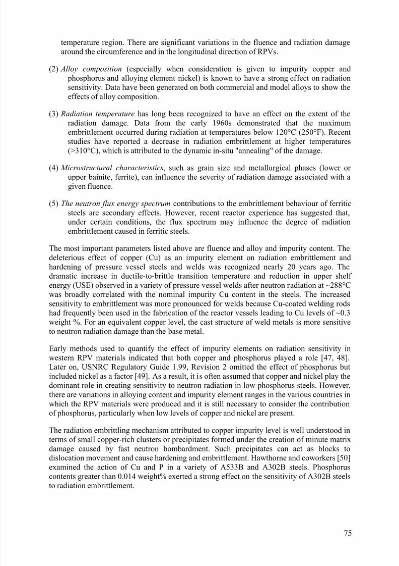
7/17/2019 IAEA 1556 Assessment and management of ageing of major nuclear power plant components important to safety …
http://slidepdf.com/reader/full/iaea-1556-assessment-and-management-of-ageing-of-major-nuclear-power-plant 85/215
temperature region. There are significant variations in the fluence and radiation damagearound the circumference and in the longitudinal direction of RPVs.
(2) Alloy composition (especially when consideration is given to impurity copper and phosphorus and alloying element nickel) is known to have a strong effect on radiationsensitivity. Data have been generated on both commercial and model alloys to show the
effects of alloy composition.(3) Radiation temperature has long been recognized to have an effect on the extent of the
radiation damage. Data from the early 1960s demonstrated that the maximumembrittlement occurred during radiation at temperatures below 120°C (250°F). Recentstudies have reported a decrease in radiation embrittlement at higher temperatures(>310°C), which is attributed to the dynamic in-situ "annealing" of the damage.
(4) Microstructural characteristics, such as grain size and metallurgical phases (lower orupper bainite, ferrite), can influence the severity of radiation damage associated with agiven fluence.
(5) The neutron flux energy spectrum contributions to the embrittlement behaviour of ferriticsteels are secondary effects. However, recent reactor experience has suggested that,under certain conditions, the flux spectrum may influence the degree of radiationembrittlement caused in ferritic steels.
The most important parameters listed above are fluence and alloy and impurity content. Thedeleterious effect of copper (Cu) as an impurity element on radiation embrittlement andhardening of pressure vessel steels and welds was recognized nearly 20 years ago. Thedramatic increase in ductile-to-brittle transition temperature and reduction in upper shelfenergy (USE) observed in a variety of pressure vessel welds after neutron radiation at ~288°C
was broadly correlated with the nominal impurity Cu content in the steels. The increasedsensitivity to embrittlement was more pronounced for welds because Cu-coated welding rodshad frequently been used in the fabrication of the reactor vessels leading to Cu levels of ~0.3weight %. For an equivalent copper level, the cast structure of weld metals is more sensitiveto neutron radiation damage than the base metal.
Early methods used to quantify the effect of impurity elements on radiation sensitivity inwestern RPV materials indicated that both copper and phosphorus played a role [47, 48].Later on, USNRC Regulatory Guide 1.99, Revision 2 omitted the effect of phosphorus butincluded nickel as a factor [49]. As a result, it is often assumed that copper and nickel play thedominant role in creating sensitivity to neutron radiation in low phosphorus steels. However,
there are variations in alloying content and impurity element ranges in the various countries inwhich the RPV materials were produced and it is still necessary to consider the contributionof phosphorus, particularly when low levels of copper and nickel are present.
The radiation embrittling mechanism attributed to copper impurity level is well understood interms of small copper-rich clusters or precipitates formed under the creation of minute matrixdamage caused by fast neutron bombardment. Such precipitates can act as blocks todislocation movement and cause hardening and embrittlement. Hawthorne and coworkers [50]examined the action of Cu and P in a variety of A533B and A302B steels. Phosphoruscontents greater than 0.014 weight% exerted a strong effect on the sensitivity of A302B steelsto radiation embrittlement.
75

7/17/2019 IAEA 1556 Assessment and management of ageing of major nuclear power plant components important to safety …
http://slidepdf.com/reader/full/iaea-1556-assessment-and-management-of-ageing-of-major-nuclear-power-plant 86/215
Unlike Cu and P, the role of nickel (Ni) in radiation hardening/embrittlement has been unclear.The contradictory reports concerning the influence of Ni in the embrittlement behaviour ofRPV steels indicated that its effect was a subtle one. The effect of Ni can be demonstratedqualitatively by studying the HY and A350LF steels (~3 weight % Ni). Although studies byLucas et al. [51] and Igata et al. [52] showed no effect of Ni on radiation embrittlement ofRPV steels, several other studies show a significant effect. In 1981, Guionnet et al. [53]
concluded that Ni was deleterious to the behaviour of A508 irradiated to a fluence of 5 × 10²³
n/m2 at 290°C. A pronounced Ni effect in increasing the radiation sensitivity of high Ni (0.7weight %) welds was reported by Hawthorne [54]. Similarly, Fisher and Buswell [55] notedthat high Ni steels (i.e., those containing >1% Ni) were much more sensitive to neutronradiation than steels containing <0.85% Ni. Soviet experience with chromium (Cr) and Ni
bearing RPV steels also indicated that Ni exerted a pronounced effect on embrittlement behaviour [56].
Odette and Lucas [57] examined the effect of Ni (0 to 1.7 weight %) on the hardening behaviour of A 533-B type steels as a function of neutron fluence, flux, temperature andmanganese and copper content. Irradiations at fluxes of 5 × 10¹⁵ and 5 × 10¹⁶ n/m2 / s gave
final fluences of 9 × 10²²
to 1.5 × 10²³
n/m2
(E>1 MeV). Low fluence irradiations were doneat 306°C and 326°C; the higher fluences were accumulated at 271°C to 288°C. The resultsindicated that Ni increased the sensitivity to radiation embrittlement in these materials, withincreasing fluence, lower flux levels, lower irradiation temperature and increased manganese(Mn) levels causing more damage. The synergisms and complex nature of the response of thealloys examined makes a complete interpretation of the mechanisms difficult.
Although the roles of Cu, P and Ni as promoters of radiation hardening and embrittlement arewell-recognized, the contribution of other elements such as manganese (Mn), molybdenum(Mo), Cr, arsenic (As) and tin (Sn), to the radiation induced behaviour of RPV steels has not
been unambiguously identified.
Significance for western PWR pressure vessels
A fluence value of 1 × 10²² n/m2 (E >1 MeV) is approximately the threshold for neutroninduced embrittlement of the ferritic steels used in western PWRs. Therefore, the beltlineregion is the region most likely to undergo significant changes in mechanical properties due toneutron radiation. Components made of materials such as Alloy 600 or Alloy 182 are lesssusceptible to neutron embrittlement. The following components are subjected to lifetimefluences less than 1 × 10²² n/m2 (E >1 MeV) or are made of materials not susceptible toneutron embrittlement:
• Core supports,• Nozzles,
• Head penetrations,
• Bottom head,
• Top head,
• Vessel flange,
• Closure studs,
• Safe ends.
76

7/17/2019 IAEA 1556 Assessment and management of ageing of major nuclear power plant components important to safety …
http://slidepdf.com/reader/full/iaea-1556-assessment-and-management-of-ageing-of-major-nuclear-power-plant 87/215
Therefore, neutron embrittlement is potentially significant only for that part of the RPV shell beltline region which is located in a high flux region.
4.1.2. Radiation embrittlement of WWER pressure vessels
Two different types of steels, 15Kh2MFAand 15Kh2NMFA in two qualities (-A or -AA)
were used to fabricate the WWER pressure vessels. These steels are affected by differentembrittlement mechanisms and behave differently from each other as discussed below.
The 15Kh2MFA type steel is used for the WWER-440 V-230 pressure vessels and the Loviisa pressure vessels. It has almost no nickel and so its behavior is controlled by its phosphorusand copper impurity content. Contrary to western practice, in which specifications strictlylimit the phosphorus content in both the base and weld metal, the original specifications usedin the CMEA countries imposed only very mild requirements on the phosphorus content,allowing as much as 0.040 weight %. The phosphorus content was originally not evenmeasured in the weld metal; it was measured only in the welding wires. The resulting
phosphorus contents in some RPVs are listed in Table 26 and are mostly close to or even
higher than the 0.040 weight % limit in the weld metal. The copper content in the 15Kh2MFAtype steel typically ranges from 0.15 and 0.20 weight % and so its effect on embrittlement issmall. Thus phosphorus is practically the only controlling impurity in the steel used for theWWER V-230 type of RPVs.
Phosphorus causes embrittlement because of thermal and radiation induced diffusion to andsegregation at the grain boundaries and also inside grains that precipitate together with otherelements like copper, manganese etc. However, intercrystalline (intergranular) fracture ofCharpy surveillance specimens is very rare, even after high neutron fluences. Most of theCharpy failures are transgranular failures. Therefore, the effects of the high phosphorussegregation in only partially understood.
The 15Kh2MFA vessels become, of course, very embrittled during radiation and most ofthem have been annealed in the last several years. Radiation embrittlement remains the mainconcern for these types of vessels.
The beltline regions of the WWER-440/V-213 pressure vessels were also manufactured from15Kh2MFA steel, but many of the V-213 pressure vessels have low phosphorous and coppercontents and are similar in impurity content to the WWER-1000 pressure vessels with strictrequirements on the residual element (Cu, P, As, Sn and Sb) content, i.e. their steel and weldsare of 15Kh2NMFAA quality. Thus, radiation embrittlement does not seem to be a limitingfactor for a 40 year vessel lifetime. Moreover, the degree of radiation embrittlement of the
WWER-440/V-213 pressure vessels is lower than that of the western PWR vessels made ofASME A 533-B material even though the V-213s are irradiated at a relatively lowtemperature, about 265°C. This is probably due to the higher structural stability of the15Kh2MFAA type steel, relative to the A 533-B steel, caused by the presence of vanadiumcarbides, which are very stable, together with the steel microstructure and the absence ofnickel.
77

7/17/2019 IAEA 1556 Assessment and management of ageing of major nuclear power plant components important to safety …
http://slidepdf.com/reader/full/iaea-1556-assessment-and-management-of-ageing-of-major-nuclear-power-plant 88/215
TABLE 26. COPPER AND PHOSPHORUS CONCENTRATIONS (WEIGHT %) IN THEBASE METAL AND WELD METAL OF WWER-440 RPVS
Plant Cladding Weld metal No. 4 Base metal
Cu P METHOD Cu P METHOD
KOLA 1 N 0.13
0.146
0.032
0.033
calc.
scrape inside
- 0.012 certif.
KOLA 2 N 0.154 0.0360.0375
calc.scrape inside
- 0.012 certif.
ARMENIA 1 N 0.16 0.030 scrape inside - 0.013 certif.
ARMENIA 2 Y - - - - - -
NOVOVORONEZH 3 N 0.15 0.031 template 0.16 0.012 template
NOVOVORONEZH 4 N 0.17 0.030 template - 0.011 certif.
KOZLODUY 1 N 0.12 0.05150.036
scrape insidecalc.
0.15 0.010 certif.
KOZLODUY 2 N 0.18 0.0360.0375
template 0.17 0.017 template
KOZLODUY 3 Y 0.20 0.036 certif. based ontest coupon
0.17 0.016 certif.
KOZLODUY 4 Y 0.04 0.021 certif. based ontest coupon
0.10 0.012 certif.
BOHUNICE 1 Y 0.150.103
0.0350.043
certif.scrape outside
0.130.091
0.0120.014
certif.scrape outside
BOHUNICE 2 Y 0.200.109
0.0360.026
certif.scrape outside
0.080.082
0.0100.010
certif.scrape outside
GREIFSWALD 1 N 0.1040.10
0.0340.043
scrape insidetemplate
0.170.18
0.0100.015
certif.template
GREIFSWALD 2 N 0.1570.15
0.0370.0320.036
certif.
scrape inside
- 0.012 certif.
GREIFSWALD 3 Y 0.12 0.035 certif. based ontest coupon
- 0.012 certif.
GREIFSWALD 4 Y 0.16 0.035 certif. based ontest coupon
0.12 0.016 certif.
The beltline regions of the WWER-1000 pressure vessels are fabricated from Type15Kh2NMFAA steel. This steel has almost no vanadium and much more nickel than the Type15Kh2MFAA material used for the WWER-440 vessels. As mentioned in Section 2, a nickelrather than vanadium alloy steel was chosen for the WWER-1000 vessels so that it would beeasier to weld the relatively large WWER-1000 forgings at lower pre-heating temperature,while still retaining the desired strength characteristics. The limits on the residual elementcontent for this steel are very strict (similar to 15Kh2MFAA type).
The nickel in the base metal was controlled to values between 1.00 and 1.50 weight %,
however, the nickel in the weld metal of many of the WWER-1000 RPVs is as high as 1.90
weight %. Thus, the nickel content in the weld metal is the controlling element for radiationembrittlement as impurity contents (Cu, P, As, Sn and Sb) are very low – see Table VII. The
78

7/17/2019 IAEA 1556 Assessment and management of ageing of major nuclear power plant components important to safety …
http://slidepdf.com/reader/full/iaea-1556-assessment-and-management-of-ageing-of-major-nuclear-power-plant 89/215
inlet water temperature of the WWER-1000 plants is higher than in the WWER-440 plants byabout 20°C (i.e. 288°C) and is similar to western PWR inlet water temperatures. Since theoperating temperatures and nickel contents are similar, the radiation embrittlement of the
beltline of the WWER-1000 vessels is somewhat comparable to the embrittlement of the beltline regions of the western vessels fabricated with A 533-B and A 508.
The radiation coefficient, AF, given in Ref. [36] and discussed in Section 3.4.4 of this report,was developed from weld metal data with a nickel content lower than 1.5 weight %.
Therefore, use of the standard values of these coefficients for determining the allowablefracture toughness of weld metal with a high nickel content (using the K IC curves for weldmetal from the Code) may not be conservative especially if weld metals also contain highcontent of manganese (approximately over 0.8 weight %). The analysis of data from WWER-1000 surveillance specimens investigation was performed. Comparison of these results withtemperature TK design prediction according to [36] is presented in figures 28 and 29.
0,0
10,0
20,0
30,0
40,0
50,0
60,0
70,0
80,0
90,0
100,0
0 5 10 15 20 25 30 35 40 45 50 55 60
Neutron fluence, Fx1022
, Neutron/m2
Т F ,
о С
Design prediction of
shift of TK
Fig. 28. Shift of ductile-to-brittle transition temperature T K of
weld metal due to irradiation.
79

7/17/2019 IAEA 1556 Assessment and management of ageing of major nuclear power plant components important to safety …
http://slidepdf.com/reader/full/iaea-1556-assessment-and-management-of-ageing-of-major-nuclear-power-plant 90/215
-40,0
-20,0
0,0
20,0
40,0
60,0
80,0
100,0
0 5 10 15 20 25 30 35 40 45 50 55 60
Neutron fluence, Fx10
22
, Neutron/m
2
Т к ,
о С
Design prediction of TK
Fig. 29. Ductile-to-brittle transition temperature T K of weld metal (absolute value).
As follows from Figure 29, real values of TK temperature do not exceed design predictions, but the question about the influence of nickel content on radiation embrittlement now is stillunder consideration.
Also, it was suspected that the data from the WWER-1000 design surveillance specimens programme (except the data from the specimens from the three ŠKODA made vessels) mightnot be representative of the radiation embrittlement of the beltline materials because thesurveillance specimens are located above the reactor core and the core barrel in a steep fluxgradient where their temperatures are at least 10°C higher than the temperature of the RPV
beltline region. Due to these reasons improvement of the surveillance programme wasrecognized to be necessary. This subject is discussed in greater detail in Section 6.
To summarize, the 15Kh2MFA weld metal in the WWER-440 V-230 pressure vessels is verysusceptible to radiation damage because of its low operating temperature and high phosphoruscontent. The Type 15Kh2MFAA material in the WWER-440 V-213 pressure vessels isrelatively resistant to radiation damage because of its good chemistry (lack of impurities) andvanadium carbides. However, this material is also exposed to relatively low operating
80

7/17/2019 IAEA 1556 Assessment and management of ageing of major nuclear power plant components important to safety …
http://slidepdf.com/reader/full/iaea-1556-assessment-and-management-of-ageing-of-major-nuclear-power-plant 91/215
temperatures where there will be more radiation damage than at higher temperatures. TheType 15Kh2NMFAA material used for the WWER-1000 pressure vessels sometimes containsrelatively high levels of nickel in the weld metal, but relatively low levels of copper and otherimpurities. Its radiation damage may be somewhat comparable to some of the materials usedin western PWR pressure vessels but in cases with high nickel content (over 1.5 weight %)and high manganese content (over 0.8 weight %) in welds it can be a limiting factor for the
RPV lifetime.
Significance for WWER pressure vessels
Radiation damage becomes significant at neutron fluences greater than 1 × 10²² n/m2 (E >0.5MeV). The design end-of-life neutron fluence for the beltline region of the WWER- 440/V-230 pressure vessels has been calculated to be to approximately 1.5 × 1024 n/m2 while for theV-213 type it is somewhat higher — up to 2.5 × 1024 n/m2. The actual RPV life depends verystrongly on the operation history and mitigation activities. Most of the V-230 plants usedummy elements in the periphery of the active core to decrease the neutron flux on the RPVwall; in other WWER reactors, a low leakage core (LLC) strategy has been implemented to
reduce the flux hence fluence.
Fig. 30. Transition temperature values as a function of operation time for Bohunice Unit 2.
The upper lines are the weld material and the lower lines are the base metal material.
Although the most irradiated part of the RPV is the base metal situated around the axial centreregion of the reactor core, the most degraded material in the WWER V-230 vessels is thecircumferential weld metal located in the lower part of the core, which is labelled the 0.1.4 or5/6 weld. Its neutron fluence reaches only about 70% of that of the maximum fluence in the
beltline region, but its embrittlement is much higher because of its high phosphorus content.This weld metal controls the vessel lifetime even after vessel annealing, as shown in Fig. 30.The circumferential weld at the top of the centre shell ring is subjected to much lowerfluences, its neutron fluence being equal to about 3% of the maximum fluence in the beltlineregion. Therefore, it is necessary to anneal only a small region around the most embrittled
weld to improve the state of the whole vessel and to extend its lifetime.
81

7/17/2019 IAEA 1556 Assessment and management of ageing of major nuclear power plant components important to safety …
http://slidepdf.com/reader/full/iaea-1556-assessment-and-management-of-ageing-of-major-nuclear-power-plant 92/215
In contrast to the embrittlement behaviour of the weld and base metals used in the V- 230s,there is no substantial difference between the embrittlement of the base and weld metals in theWWER-440/V-213 pressure vessels. The only difference is that the initial transitiontemperature of the weld metal is much higher than in the base metal. Thus, the weld metalslocated at 0.1.4 again control the vessel lifetime.
There is only a small difference between the fluences in the circumferential weld metalsituated in the lower part of the active core and the base metal exposed to the maximumfluences in the beltline region of the WWER-1000 pressure vessels. In this case, for weldmetals with nickel content lower than 1.5 weight %, there is no substantial difference in theembrittlement of the base and weld metal. However, weld metals with high nickel content (upto 1.9 weight %) and high manganese content (over 0.8 weight %) experience greaterembrittlement than the base metal. Thus, in most cases, the weld metals remain the controllingmaterials for the RPV embrittlement.
The IAEA conducted a coordination research programme (CRP) on the effects of Ni contenton radiation embrittlement of WWER-1000 RPVs (see 5.3.5).
4.2. THERMAL AGEING
4.2.1. Description of mechanism
Thermal ageing is a temperature, material state (microstructure) and time dependentdegradation mechanism. The material may lose ductility and become brittle because of verysmall microstructural changes in the form of precipitates coming out of solid solution. In thecase of RPV steel with impurity copper, the important precipitates are copper-rich (however,there could be other precipitates). The precipitates block dislocation movement therebycausing hardening and embrittlement. The impurity copper in RPV steel is initially trapped in
solution in a super-saturated state. With time at normal PWR operating temperatures(~290°C), it may be ejected to form stable precipitates as the alloy strives toward a morethermodynamically stable state, even if there is no radiation damage. As discussed in Section4.1, neutron-induced structural damage promotes the copper precipitation process.
The effects of long-term aging at temperatures up to 350°C on the ductile-to-brittle transitiontemperature of RPV steels have been summarized in a paper by Corwin et al. [58]. The workwas sponsored by the USNRC and performed at the Oak Ridge National Laboratory and theUniversity of California, Santa Barbara. Corwin et al. concluded that "most of the data fromthe literature suggest that there is no embrittiement in typical RPV steels at these temperaturesfor times as great as 100,000 h...."
Some of the more important data is discussed next. The reader is referred to the Corwin et al. paper for additional references and discussions. Data are available on the behaviour of A 302Grade B, A 533 Grade B and A 508 Class 2 and Class 3, and equivalent non-US steels.Limited thermal ageing studies by Potapovs and Hawthorne [59] for P-bearing A 302 Grade Bsteels at 290°C revealed no significant shift in the ductile to brittle transition temperature(decrease of 5 to 14°C). DeVan et al. [60] have reported that A 533 Grade B Class 1 platematerials from the Arkansas 1 reactor shifted -4 to 10°C after thermal ageing at 280°C for93,000 hours. A 508 Class 2 forging materials encapsulated outside the beltline region of theOconee Unit 3 reactor showed an increase of about 1°C after exposure to a temperature of282°C for 103,000 hours [60]. Also, weld metal specimens from the Arkansas 1 and Oconee
Unit 3 reactors showed changes in the ductile-to-brittle transition temperature of -8 to 0°C
82

7/17/2019 IAEA 1556 Assessment and management of ageing of major nuclear power plant components important to safety …
http://slidepdf.com/reader/full/iaea-1556-assessment-and-management-of-ageing-of-major-nuclear-power-plant 93/215
after exposure up to 103,000 hours at about 280°C [60]. The weld metal specimens weremade with Linde 80 MnMoNi weld wire typical of that used for submerged arc welds.
Fukakura et al. [61] studied the effect of thermal ageing on A 508 Class 3 steel and concludedthat after thermal ageing for 10,000 hours at temperatures of 350°C, 400°C and 450°C, theincrease in the nil-ductility transition temperature was small. The JIC and J-R resistance curves
also decreased somewhat as a result of thermal ageing. It appears that grain size may be animportant variable in assessing thermal ageing embrittlement. The effect of grain size onthermal ageing embrittlement may be due to grain boundary embrittlement by impuritysegregation (e.g. P) at the grain boundaries.
Three studies have been conducted in Germany of the effects of thermal ageing of low alloy pressure vessel steels. All the tests were conducted at temperatures typical of operatingtemperatures and for durations of 10,000 to 100,000 hours. All found negligible detrimentaleffects. In the first study, base, butt-weld heat-affected zone, and weld-simulated heat affectedzone 20 Mn Mo Ni 5 material was clamped to the main coolant lines of three NPPs for about60,000 hours (7 years). The ageing temperature was approximately 290°C (555°F). The
toughness transition temperature curves for these materials were unchanged at the end of theexposure period. In the second study, which was part of the German Component SafetyProgramme, base and heat-affected zone 20 Mn Mo Ni 5 and 2 Cr 37 material was placed in alaboratory furnace at 320°C (608°F) for up to 10 hours. Again, there were no significantchanges in the toughness transition temperature curves. In the third study, parts of theObrigheim main coolant line were removed after approximately 100,000 hours of operation atabout 285°C (545°F) and then destructively examined (tensile and Charpy testing). TheObrigheim main coolant line was fabricated from 2 Ni Mo Cr 37 material. The mechanicaltesting indicated that there had been no thermal embrittlement of this material during the100,000 hours of operation.
In contrast, Hasegawa et al. [62] observed some small shifts in the transition temperature forCu and P-bearing A 533-B steels after thermal ageing at temperatures near 300°C and amaximum shift at about 500°C, well beyond the operating temperature of PWRs. Similar
behaviour was reported for coarse-grain simulated and thermally aged heat-affected zones ofA 533-B steel by Druce et al. [63]. However, this ageing was associated with temperatureshigher than 400°C and with P segregation to the grain boundaries.
The 15Kh2MFA and 15KMMFAA steels used to fabricate the WWER-440 pressure vesselsalso do not appear to be susceptible to thermal ageing, even when they contain relatively high
phosphorous impurity levels. The results from the thermal ageing surveillance specimenslocated in the upper plenums of the WWER-440 V-213 pressure vessels and removed and
tested after 10 years at about 300°C indicate that the shift in the Charpy ductile to brittletransition temperature is small. These results are supported by Charpy ductile to brittletransition temperature measurements from RPV trepans removed from closed plants(Novovoronezh 1 and 2), as well as boat samples taken from operating plants. Laboratorytests carried out at 350°C for 10 hours also showed that the transition temperatures remainstable within the normal data scatter.
The type 15Kh2NMFA steel used to fabricate the WWER-1000 pressure vessels is slightlysusceptible (a shift in the ductile-brittle transition temperature of 10 to 20°C) to thermalageing at operating temperatures, due to the high nickel and low vanadium content of thismaterial. Even though the Standard [35] recommends that thermal ageing should not be taken
into account for this type of steel, the most recent results show some non-negligible shift thatshould be considered and incorporated into the Standard [64].
83

7/17/2019 IAEA 1556 Assessment and management of ageing of major nuclear power plant components important to safety …
http://slidepdf.com/reader/full/iaea-1556-assessment-and-management-of-ageing-of-major-nuclear-power-plant 94/215
4.2.2. Significance
Thermal ageing does not appear to be generic but depends on the heat treatment, chemicalcomposition and service time at temperature of the material. Microstructural aspects such asgrain size and the phases present may also be involved in the thermal ageing of low alloysteels. The experimental results discussed above show that the thermal ageing mechanism
should be classified as an insignificant degradation mechanism for PWR RPVs. In addition, itcan be argued that thermal ageing degradation is at least partly taken into account in theRT NDT shift prediction methodologies since all the PWR surveillance capsule specimens areirradiated at slightly higher temperatures than the RPV walls.
Thermal ageing does not appear to be significant for WWER type reactors, even for materialswith high phosphorous content. The results from the surveillance specimens after 10 years ofoperation at about 300°C as well as the results from testing of the trepans and boat samplesfrom components aged more than 15 years have not shown any substantial transitiontemperature increases.
4.3. TEMPER EMBRITTLEMENT
4.3.1. Description of mechanism
The term "temper embrittlement" has been traditionally used to describe the embrittlement ofstructural steels, mostly by impurity phosphorus concentrating at the grain boundaries.Temper embrittlement is found in quenched and tempered ferritic materials, especially when atempering temperature around 450-500°C is used. The role of phosphorus in the overallembrittlement of western-type RPV materials has been a subject of much discussion over theyears. The problems have been compounded by the lack of qualified data and the variation ofalloy compositions and irradiation conditions. However, the effect of phosphorus in weld
metals and the heat affected zones is of concern, particularly when a thermal annealing may be applied to restore toughness. The propensity of phosphorus to migrate to grain boundariesin the RPV materials and thereby cause embrittlement under certain thermal conditions should
be accounted for. The generation of a non-hardening embrittled condition is theoretically possible (called temper embrittlement) if phosphorus levels are high enough and the diffusion paths and thermal activation are available.
4.3.2. Significance
RPV steels with phosphorus content well above about 0.02 weight % may be susceptible totemper embrittlement during fabrication. However, the western RPV materials normally
contained less than 0.020 weight % phosphorus. Therefore, it is unlikely that any westernRPVs will exhibit temper embrittlement. If a 450°C thermal anneal of an irradiated RPV isrequired for recovery of the fracture toughness, the possibility of temper embrittlement should
be evaluated.
4.4. FATIGUE
4.4.1. Description of mechanism
Fatigue is the initiation and propagation of cracks under the influence of fluctuating or cyclicapplied stresses. The chief source of cyclic stresses are vibration and temperature fluctuations.As discussed previously, the PWR RPV is designed so that no subcomponent of the RPV isstressed above the allowable limits described in the ASME Boiler and Pressure Vessel Code,
84

7/17/2019 IAEA 1556 Assessment and management of ageing of major nuclear power plant components important to safety …
http://slidepdf.com/reader/full/iaea-1556-assessment-and-management-of-ageing-of-major-nuclear-power-plant 95/215
Section III (or equivalent national codes) during transient conditions and the allowable cyclicfluctuations do not violate Miner's fatigue rule. Once a crack is detected, it's behaviour undercyclic loading is analysed according to Section XI of the ASME Code or similar codes.
The RPV should be designed in such a way that no subcomponent is stressed above theallowable limit, which is a usage factor of one. Even if the usage factors go slightly above one,
fatigue cracks are not expected because the safety factors discussed in Section 3 are used inthe design.
4.4.2. Significance
Significance for western pressure vessels
The RPV closure studs have the highest usage factor of any the subcomponents. However, theusage factor for the RPV closure studs are of the order of 0.66 for the 40-year design life. Thehead penetrations for the control rod drives and the vent tubes have very low fatigue usagefactors. The RPV inlet and outlet nozzles also have relatively low fatigue usage factors.
Unless there is some condition that results in extreme vibration to any of the RPVsubcomponents, fatigue damage is considered an insignificant degradation mechanism in theassessment and management of the PWR pressure vessels.
Significance for WWER pressure vessels
From a fatigue point of view, the most important subcomponents of the WWER pressurevessels are the closure studs. The lifetime of the WWER-440 closure studs is limited to some15 years of operation, when the expected usage factor will reach one. However, there is littlechance of failure because these studs are tested every four years by ultrasonic and eddycurrent methods. Moreover, their exchange is a standard maintenance procedure, which is
planned in advance.The second most important WWER pressure vessel components are the primary nozzles,especially the cladding on their inner radius. However, the calculated usage factors for theselocations are less than one for the whole design lifetime. And again, these parts are includedin the ISI performed every four years when ultrasonic, eddy-current and dye-penetrantmethods are applied.
4.5. CORROSSION
Corrosion is the reaction of a substance with its environment that causes a detectable change
which can lead to deterioration in the function of the component or structure. In the presentcontext, the material is steel and the reaction is usually an electrochemical (wet) reaction. Theappearance of corrosion is governed by the so-called corrosion system consisting of the metaland the corrosive medium (the environment) with all the participating elements that caninfluence the electrochemical behaviour and the corrosion parameters. The variety of possiblechemical and physical variables leads to a large number of types of corrosion, which can besubdivided into:
- corrosion without mechanical loading (uniform corrosion and local corrosion attack,selective corrosion attack as e.g. intergranular corrosion)
- corrosion with mechanical loading (stress corrosion cracking, corrosion fatigue)
- flow assisted corrosion attack (erosion-corrosion, flow induced corrosion, cavitations).
85

7/17/2019 IAEA 1556 Assessment and management of ageing of major nuclear power plant components important to safety …
http://slidepdf.com/reader/full/iaea-1556-assessment-and-management-of-ageing-of-major-nuclear-power-plant 96/215
During the electrochemical processes, the metal ions dissolve in liquid electrolyte (anodicdissolution) and hydrogen is produced. This is the process of material loss and creation ofcorrosion products. When mechanical stresses or strains are also present, the anodicdissolution of the metal can be stimulated, protection layers (oxide layers) can rupture orhydrogen interaction with the metal (absorption) can be promoted which can producesecondary damage. The combined action of a corrosive environment and mechanical loading
can cause cracking even when no material degradation would occur under either the chemicalor the mechanical conditions alone.
Water chemistry control during operation, as well as during shutdown, is very important withrespect to avoiding corrosion problems. Thus the content of al additives has to be carefullymonitored and the ingress of impurities has to be strictly avoided, e.g. during stand still
periods and maintenance work. The water chemistry regimes which are used in the primarycoolant circuits of the various types of reactors and which have proven effective are presentedin Table 27.
86
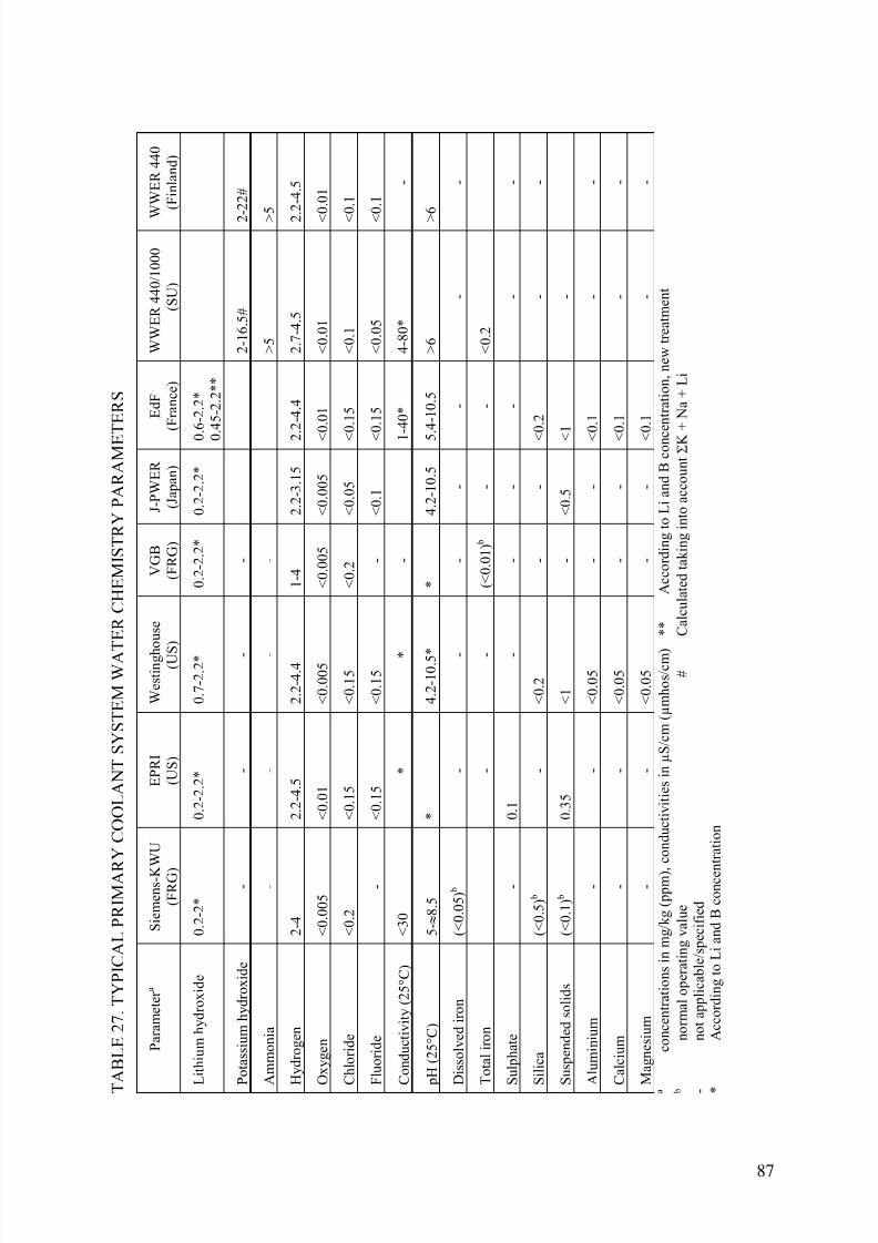
7/17/2019 IAEA 1556 Assessment and management of ageing of major nuclear power plant components important to safety …
http://slidepdf.com/reader/full/iaea-1556-assessment-and-management-of-ageing-of-major-nuclear-power-plant 97/215
T
A B L E 2 7 . T Y P I C A L P R I M A R
Y C O O L A N T S Y S T E M W A T E R C H E M I S T R Y P A R A M E T E R S
P a r a m e t e r a
S i e m e n s - K
W U
( F R G )
E P R I
( U S )
W e s t i n g h
o u s e
( U S
)
V G B
( F R G )
J - P W E R
( J a p a n )
E d F
( F r a n c e )
W W E R 4 4 0 / 1 0 0 0
( S U )
W
W E R 4 4 0
( F i n l a n d )
L i t h i u m h y d r o x i d e
0 . 2 - 2 *
0 . 2 - 2 . 2 *
0 . 7 - 2 . 2 *
0 . 2 - 2 . 2 *
0 . 2 - 2 . 2 *
0 . 6 - 2 . 2 *
0 . 4 5 - 2 . 2 * *
P o t a s s i u m h y d r o x i d e
-
-
-
-
2 - 1 6 . 5 #
2 - 2 2 #
A m m o n i a
-
-
-
-
> 5
>
5
H y d r o g e n
2 - 4
2 . 2 - 4 . 5
2 . 2 - 4 . 4
1 - 4
2 . 2 - 3 . 1 5
2 . 2 - 4 . 4
2 . 7 - 4 . 5
2 . 2 - 4 . 5
O x y g e n
< 0 . 0 0 5
< 0 . 0 1
< 0 . 0 0 5
< 0 . 0 0 5
< 0 . 0 0 5
< 0 . 0 1
< 0 . 0 1
<
0 . 0 1
C h l o r i d e
< 0 . 2
< 0 . 1 5
< 0 . 1 5
< 0 . 2
< 0 . 0 5
< 0 . 1 5
< 0 . 1
<
0 . 1
F l u o r i d e
-
< 0 . 1 5
< 0 . 1 5
-
< 0 . 1
< 0 . 1 5
< 0 . 0 5
<
0 . 1
C o n d u c t i v i t y ( 2 5 ° C )
< 3 0
*
*
-
1 - 4 0 *
4 - 8 0 *
-
p H ( 2 5 ° C )
5 - ≈ 8 . 5
*
4 . 2 - 1 0 . 5 *
*
4 . 2 - 1 0 . 5
5 . 4 - 1 0 . 5
> 6
>
6
D i s s o l v e d i r o n
( < 0 . 0 5 ) b
-
-
-
-
-
-
-
T o t a l i r o n
-
-
( < 0 . 0 1 ) b
-
-
< 0 . 2
S u l p h a t e
-
0 . 1
-
-
-
-
-
-
S i l i c a
( < 0 . 5 ) b
-
< 0 . 2
-
-
< 0 . 2
-
-
S u s p e n d e d s o l i d s
( < 0 . 1 ) b
0 . 3 5
< 1
-
< 0 . 5
< 1
-
A l u m i n i u m
-
-
< 0 . 0 5
-
-
< 0 . 1
-
-
C a l c i u m
-
-
< 0 . 0 5
-
-
< 0 . 1
-
-
M a g n e s i u m
-
-
< 0 . 0 5
-
-
< 0 . 1
-
-
a
c o n c e n t r a t i o n s i n m g / k g ( p p m ) , c o n d u c t i v i t i e s i n µ S / c m ( µ m h o s / c m ) * *
A c c o r d i n g t o L i a n d B c o n c
e n t r a t i o n , n e w t r e a t m e n t
b
n o r m a l o p e r a t i n g v a l u e
#
C a l c u l a t e d t a k i n g i n t o a c c o u n t Σ K
+ N a + L i
-
n o t a p p l i c a b l e / s p e c i f i e d
*
A c c o r d i n g t o L i a n d B c o n c e n t r a t i o n
87

7/17/2019 IAEA 1556 Assessment and management of ageing of major nuclear power plant components important to safety …
http://slidepdf.com/reader/full/iaea-1556-assessment-and-management-of-ageing-of-major-nuclear-power-plant 98/215
4.5.1. Primary water stress corrosion cracking (PWSCC)
4.5.1.1. PWR control rod drive mechanism (CRDM) nozzles
Many western PWRs have CRDM (control rod drive mechanisms) penetrations in the RPVhead made of stainless stain steel and Alloy 600. The lower portion of each penetration is
made of Alloy 600, a high nickel content material, and is attached to the inside surface of the pressure head with a partial-penetration weld. The weld and the CRDM nozzle wall above theweld are part of the primary coolant primary vessel boundary. The upper portion of eachCRDM penetration is made of stainless steel which is joined to the Alloy 600 material with adissimilar metal weldment and joined to the CRDM housing with a screw fitting and sealweld. A typical Westinghouse-type CRDM penetration is shown in Fig. 31. There aretypically 40 to 90 penetrations in a reactor pressure vessel depending on the plant size,distributed over each pressure vessel head as shown in Fig. 32. The CRDM penetration designand materials are essentially the same for all PWRs in Belgium, Brazil, China (includingTaiwan, China), France, Japan, Republic of Korea, South Africa, Spain, Sweden, Switzerland,and the United States. However, in Germany the only PWRs with Alloy 600 penetrations are
Obrigheim which is no longer in operation and Mülheim-Kärlich, which due to other reasonsnever went in operation.
Mechanism description
PWSCC requires the simultaneous presence of high tensile stresses, a corrosive environment(in this case, high temperature water) and a susceptible microstructure [65]. The PWSCCdamage rate increases as a function of stress to the power of 4 to 7, i.e.:
damage rate ∝ σ4 (38)
where
σ is the maximum principal tensile stress, which includes both applied and residual stresses.This correlation suggests that a 50% reduction in the effective stress will result in a 16-folddecrease in the damage rate and a corresponding increase in PWSCC initiation time.
PWSCC is also a thermally activated process that can be described by an Arrheniusrelationship of the form:
damage rate ∝ e-Q/RT (39)
where
Q is activation energy, R is universal gas constant and T is temperature. Various estimates forthe activation energy, Q, of Alloy 600 tube materials have been derived from laboratorystudies and field experience. The estimates range from 163 to 227 kJ/mole (39 to 65kcal/mole), with a best-estimate value of 209 kJ/mole (50 kcal/mole) (Ref. [65] and referencestherein). Estimates for the activation energy for Alloy 600 components fabricated from barmaterial may be different than those fabricated from tube materials. Both the initiation andgrowth of PWSCC are very sensitive to temperature. For example, a PWSCC initiation timewould typically be reduced by a factor of two for a 10°C (18°F) increase from an operatingtemperature of 315°C (600°F).
88
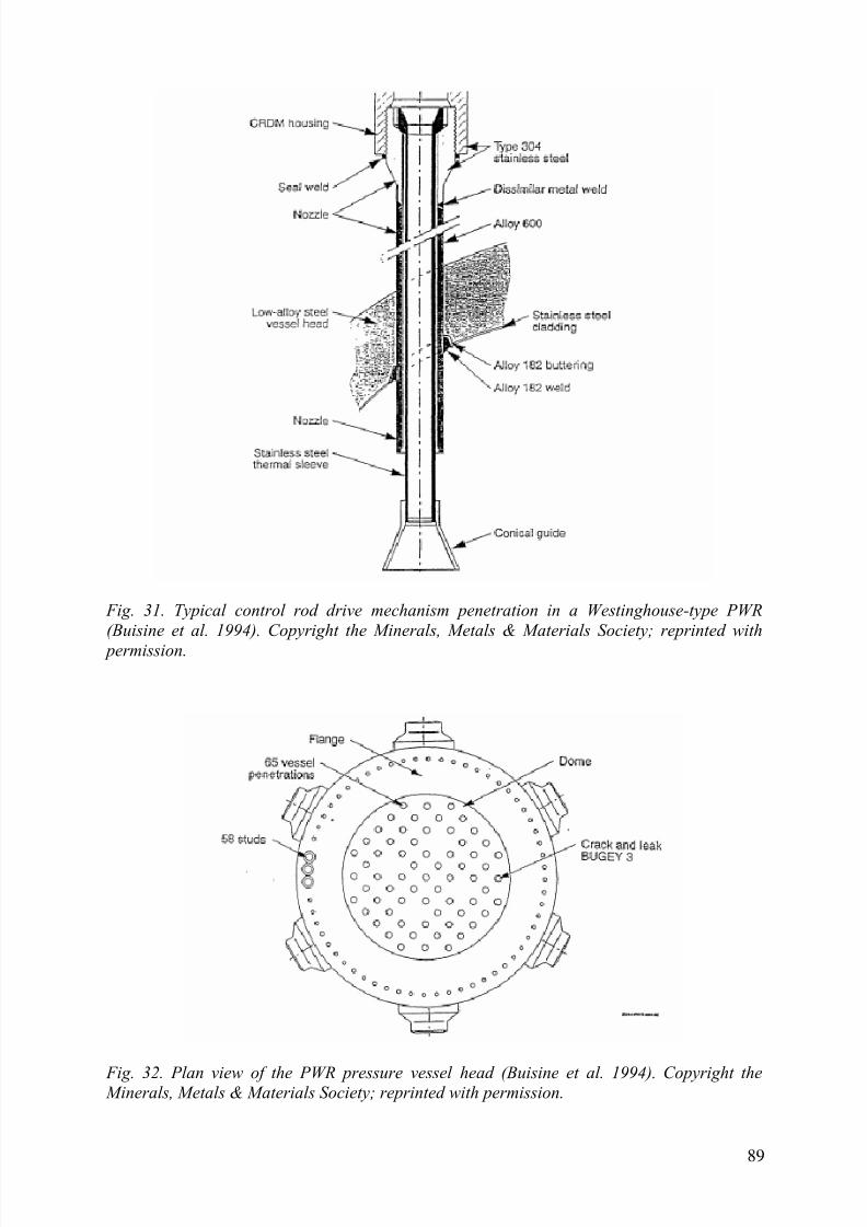
7/17/2019 IAEA 1556 Assessment and management of ageing of major nuclear power plant components important to safety …
http://slidepdf.com/reader/full/iaea-1556-assessment-and-management-of-ageing-of-major-nuclear-power-plant 99/215
Fig. 31. Typical control rod drive mechanism penetration in a Westinghouse-type PWR
(Buisine et al. 1994). Copyright the Minerals, Metals & Materials Society; reprinted with
permission.
Fig. 32. Plan view of the PWR pressure vessel head (Buisine et al. 1994). Copyright the Minerals, Metals & Materials Society; reprinted with permission.
89

7/17/2019 IAEA 1556 Assessment and management of ageing of major nuclear power plant components important to safety …
http://slidepdf.com/reader/full/iaea-1556-assessment-and-management-of-ageing-of-major-nuclear-power-plant 100/215
Field experience and research results show that the PWSCC resistance of Alloy 600 is highestwhen the grain boundaries are covered with continuous or semi continuous carbides. Forexample, the PWSCC initiation time increases by a factor of five as the grain boundarycarbide coverage increases from 0 to 100% [66]. The percentage of the grain boundariescovered with intergranular carbides depends on the material heat treatment temperature andtime, carbon content and grain size. High temperature heat treatments which put the carbides
back in solution result in good carbide coverage of the grain boundaries and a microstructurethat is more resistant to PWSCC. Also, larger grain material has less grain boundary area thansmall grain material, so it is easier to get complete coverage with larger grains.
Primary coolant chemistry has a secondary effect on the time of PWSCC initiation. However,increasing the hydrogen concentration in the primary coolant decreases the PWSCC initiationtime. Therefore, EPRI's PWR Primary Water Chemistry Guidelines [67] recommend that
plant operators maintain hydrogen concentrations in the range of 25 to 35 cm3/kg, which isnear the lower end of the typically used range of 25 to 50 cm3/kg.
Penetration fabrication and installation
The penetration material and the installation process can determine whether the penetrationsare susceptible to PWSCC or not. The penetrations in many Westinghouse plants, all B&W
plants, and several Combustion Engineering plants were fabricated from Alloy 600 pipes, aswere the penetrations in the Swedish plants. The penetrations in all French, Swiss and Belgian
plants and the remaining Westinghouse and Combustion Engineering plants were fabricatedfrom Alloy 600 bars. One difference in the bar materials is that the French, Swiss and Belgian
plants used forged bars whereas the Westinghouse and Combustion Engineering plantsgenerally used rolled bars. A machining process was used to fabricate the penetrations.Machining introduces a thin layer of cold-worked material on the machined surfaces. Theyield strength of the cold-worked material is higher than that of the base metal. In addition,
machining also introduces compressive residual stresses. The penetration material was usuallyheat treated in the temperature range of 870 to 980°C (1,600 to 1,800°F) for 90 minutes orlonger. One exception is the French PWRs, where the material was heat treated in thetemperature range of 710 to 860°C (1,310 to 1,580°F) if the yield strength exceeded 343 MPa(49.7 ksi). A higher heat treatment temperature results in lower yield strength and lowerresidual stresses. Also, a higher heat treatment temperature (above the solution temperature) isone of the parameters that can result in a more PWSCC resistant microstructure. The Alloy-600 penetrations at Obrigheim were stress relieved during fabrication, and this is probably thereason that cracks have not been detected in this material.
The penetrations are shrunk fit into the vessel head openings by dipping them into liquidnitrogen and quickly inserting them into the openings. When the penetration returns toambient temperature, a tight fit results. Then, the penetrations are attached to the bottom ofthe head with a partial penetration weld, shown in Fig. 31. These attachment welds are madewith multiple passes (up to an estimated 50 passes) of Alloy 182 weld metal. Due to thegeometry of the vessel head, the attachment welds are not axisymmetric, except the one forthe central penetration, and therefore, the amount of weld metal deposited around the
penetration is not uniform. The 180-degree location has a wider weld bead than the 0-degreelocation. Also, the average volume of weld metal deposited around the penetration variesfrom plant to plant. The standard minimum partial penetration weld size is given in Figure
NB-4244(d)-l(d) of Section III of the ASME Code. Some fabricators may have used larger
weld sizes to ensure that the minimum size was met. As their experience increased, thefabricators may have been able to use smaller weld sizes on later heads. In addition, the size
90

7/17/2019 IAEA 1556 Assessment and management of ageing of major nuclear power plant components important to safety …
http://slidepdf.com/reader/full/iaea-1556-assessment-and-management-of-ageing-of-major-nuclear-power-plant 101/215
requirements in the ASME Code were changed between the 1968 and 1971 editions to permitan alternate configuration for partial penetration weld connections. Use of the alternateconfiguration will reduce the depth of the weld groove by about 40% and the length of theweld leg (length of the weld in contact with the nozzle) by about 17%.
The weld metal shrinks as it cools and pulls the lower end of the penetration radially outward
(because of the difference in the axial location of the 0 and 180° weld metal), bending the penetration and ovalizing its cross-section at the weld region [68]. The ovality (the differencein major and minor diameters, as a percentage of the original diameter) can be as high as 2%in the penetration cross-section at the downhill location of the weld. A penetration with alarger setup angle or larger welds has more welding-induced deformation, that is, bending ofthe penetration and ovalization of its cross-section. The ovalized cross section has its majordiameter along the circumferential direction of the vessel head. The deformation also causesthe penetration above the weld to lose its interference fit with the head opening.
Residual stresses
The welding-induced residual stresses on the inside surface of the penetration have beenmeasured using a mockup of a typical CRDM penetration [69, 70]. As expected, themeasurements show that the highest welding-induced stresses on the inside surface are in the
peripheral penetrations, for which the setup angle is the largest. The stresses are highest at the0-degree location, toward the periphery of the vessel head. The circumferential stressesexceed the axial stresses by about a factor of 1.6. Stresses at the 180-degree location on
peripheral penetrations are lower, but the circumferential stress is still higher than the axialstress. As the setup angle decreases, the magnitude of the measured circumferential and axialstresses and the difference between them also reduce.
Axial tensile stresses are generally lower than hoop stresses; but, later than axial crack
initiation, they can initiate a circumferential crack on some parts of nozzles. However,complete circumferential through wall crack is an unlikely event because the axial stressesacross the wall thickness vary from tensile to compression and cannot support the growth of acircumferential crack in current license period.
Penetration environment
The penetration temperature is determined by the temperature of the coolant in the upperhead. Estimated head temperatures vary from 289 to 327°C (552 to 621°F). The penetrationtemperatures could be affected by the bypass of the vessel inlet flow into the upper head,which varies from an estimated 5% in some Westinghouse-designed plants to 0.5% in
Combustion Engineering-designed plants. Framatome is modifying the vessel internals toincrease the bypass flow in some of its plants. Lower penetration temperatures are beneficialin mitigating PWSCC. Measurements have been taken on some reactor pressure vessel headsto confirm differences between center and peripheral nozzles in cold domes (cold heads) andhot domes (hot heads), but the French field experience doesn't show any significantdifferences in initiation time for hot and cold domes. As will be discussed Section 5,Inspection and Monitoring Requirements and Technologies, Bamford and Hall [71] reportedthat there has been approximately 41 head penetrations in which pressure boundary leaks have
been discovered as of June 2004. Figure 1 of Bamford and Hall [71] paper provides the resultsfrom reactor vessel head penetration inspections. The Figure 1 of [71] has been reproduced asFigure 33 of this TECDOC. As may be seen in Figure 33, the experience in US plants has
been very strongly correlated to the time and temperature of service.
91

7/17/2019 IAEA 1556 Assessment and management of ageing of major nuclear power plant components important to safety …
http://slidepdf.com/reader/full/iaea-1556-assessment-and-management-of-ageing-of-major-nuclear-power-plant 102/215
Operating experience
A CRDM penetration began leaking in September 1991 at Bugey 3, a French PWR. The leakoccurred during a hydrotest (after 10 years of operation) conducted at a pressure of 20.7 MPa(3,000 psi) and about 80°C (175°F) and was detected with acoustic emission monitoringequipment [68]. The leak rate was about 0.7 L/h (0.003 gpm).
Subsequent inspection revealed that the leaking crack was axially oriented and located on thedownhill side at an elevation corresponding to the lowest portion of the partial penetrationweld attaching the penetration to the RPV head. Several other approximately axial (withinabout 15 degrees of being axial) cracks were also found on the inside surface of the
penetration at both the downhill and uphill locations. A sketch showing the crack locations isshown in Fig. 34. In addition to the leaking crack, there was another through-wall axial cracklocated at the counterbore and below the weld at the uphill location, shown in Fig. 34. Thiscrack is in the portion of the penetration wall that does not constitute a part of the primary
pressure boundary.
Fig. 33. Results of Reactor Vessel Head Penetration Inspections,Updated through 12/31/04, Compiled by Larry Mathews.
Destructive examination of the damaged penetration material revealed that a through-wallPWSCC crack was initiated on the inside surface (downhill location) at the upper corner ofthe counterbore; it was 25 mm (1.0 in.) long on the inside surface and 2 mm (0.08 in.) long onthe outside surface. The crack length was greater underneath the inside surface; its maximumvalue was 52 mm (2.0 in.) [72]. The crack also penetrated the Alloy 182 weld metal over a
length of about 15 mm (0.6 in.) and to a maximum depth of 2.7 mm (0.1 in.). Theexamination also revealed oxidation at the crack tip, which implies that the through-wall
92

7/17/2019 IAEA 1556 Assessment and management of ageing of major nuclear power plant components important to safety …
http://slidepdf.com/reader/full/iaea-1556-assessment-and-management-of-ageing-of-major-nuclear-power-plant 103/215
crack was present prior to the hydrotest [69]. In addition, there were no boric acid deposits onthe surface of the head opening, indicating that significant leakage did not occur duringoperation [68].
Fig. 34. Location of cracks on the Bugey 3 CRDM nozzle (Buisine 1994)
Copy tight the Minerals Metals &. Material Society reprinted with permission.
The destructive examination also revealed the presence of two circumferential cracks on theoutside surface of the penetration: one in the weld, which was found to be a hot crack
resulting from the original welding process; and one in the base metal, which was connectedto the axial through-wall crack. The crack in the base metal was on the downhill side justabove the weld, making an angle of 30 degrees with the horizontal plane. The crack was about3 mm long and 2.25 mm deep. Further examination verified that the crack was caused byPWSCC [73]. It appears that the primary coolant may have leaked through the axial crack intothe annular region between the nozzle wall and the vessel head and caused PWSCC on theoutside surface, or the circumferential crack in the base metal was part of the through-wallaxial crack.
After the leakage was detected at Bugey 3, the CRDM penetrations at plants in Belgium,Brazil, France, Japan, South Africa, Spain, Sweden, Switzerland and the USA were inspected.According to Thomas R. Mager [74] inspection results to April 30, 2002 showed that out of7,384 penetrations, 6,373 penetrations were inspected and 318 penetrations were identified ashaving indications (5%). The results of these inspections are summarized in Table 28 [74].Most of the indications were found in the French PWRs [75, 76], in part, because moreFrench penetrations have been inspected; however, indications were also found in Sweden,Switzerland and the USA. If the inspection results from France are excluded, the percentageof penetrations with indications in the remainder of the world is approximately 0.5%.
Most of the penetration cracks were short (less than 25 mm) and axial, making a small anglewith the vertical, initiated on the inside surface and located at either the uphill or downhill
93

7/17/2019 IAEA 1556 Assessment and management of ageing of major nuclear power plant components important to safety …
http://slidepdf.com/reader/full/iaea-1556-assessment-and-management-of-ageing-of-major-nuclear-power-plant 104/215
side of the peripheral penetrations and near the partial penetration weld. The maximum angleof inclination was about 30 degrees. The first circumferential indications where found at three
plants. These indications were on the outside surface of penetrations at Bugey 3, in theattachment weld at Ringhals 2 and at Zorita [77]. A few more penetrations have been foundwith circumferential cracks over the past few years. A total of 19 circumferential cracksnozzles above the weld or in the weld elevation zone were detected at Crystal River 3, Davis-
Besse, North Anna 2, and Oconee 2 and 3 [78]. An additional 16 circumferential cracks weredetected in nozzles below the weld. Cracks below the weld are not considered safetysignificant [78]. Today, 53 leaking penetrations (32 in the nozzles and 21 in the weld) have
been detected in the United States plus one in France and one in Japan. A few cracks werefound through wall located below the welds in the region of penetration that is not part of thereactor coolant pressure boundary [76,79].
TABLE 28. OPERATIONAL INFORMATION AND INSPECTION RESULTS FOR UNITEXAMINED
Country Plant Type UnitsInspected
K Hours Head Temp(˚F)
TotalPenetrations
PenetrationsInspected
Penetrationswith
IndicationsCPO 6 80-107 569-599 390 390 23
CPY 28 42-97 552 1820 1820 126
France
1300 MW 20 32-51 558-597 1542 1542 95
Sweden 3 Loop 3 75-115 580-606 195 190 8
Switzerland 2 Loop 2 148-154 575 72 72 2
2 Loop 7 105-108 590-599 276 243 0
3 Loop 7 99 610 455 398 0
Japan
4 Loop 3 46 590 229 193 0
2 Loop 2 115 588 98 98 0Belgium
3 Loop 5 60-120 554-603 337 337 6Spain 3 Loop 5 65-70 610 325 102 0
Brazil 2 Loop 1 25 NA 40 40 0
SouthAfrica
3 Loop 1 NA NA 65 65 6
Slovenia 2 Loop 1 NA NA 49 49 0
2 Loop 3 NA NA 49 49 3SouthKorea 3 Loop 2 NA NA 130 130 2
2 Loop 2 170 590 98 98 0
3 Loop 1 NA NA 65 20 12
UnitedStates
4 Loop 18 NA NA 1149 537 35
Totals 117 - - 7387 6373 318As of April 30 2002
CRDM penetration cracking that was probably caused by chemical attack due to intrusion ofdemineralizer resins containing sulphur into the reactor coolant system has occurred in the160-MW, one-loop Spanish PWR, Zorita. A total of 171 crack indications were found in 34 ofthe 37 Zorita penetrations [77, 80]. Most of the indications were axial and located in the freespan region of the penetrations rather than near the attachment welds. These indications werenot included in Table 28 because the cracking was not PWSCC and the Zorita waterchemistry excursion is not typical of what might occur in most PWRs.
94

7/17/2019 IAEA 1556 Assessment and management of ageing of major nuclear power plant components important to safety …
http://slidepdf.com/reader/full/iaea-1556-assessment-and-management-of-ageing-of-major-nuclear-power-plant 105/215
Operating e xperience in the United States of America
The susceptibility of head penetrations to PWSCC appears to be strongly linked to theoperating time and temperature of the reactor pressure vessel head. Problems related toPWSCC have therefore increased as plants have operated for longer periods of time.
G. White et al published a paper titled, "Summary of US PWR Reactor Vessel Head NozzleInspection Results" [78], which provides a summary of USA PWR plants head penetrationcracking as well as a summary of head penetration leakage. G. White et al reported that therewas a total of 144 penetrations with cracks in the tube or weld metal (81 tubes and 64 welds).G. White et al also reported 51 leaking penetrations (31 tubes and 20 welds).
As stated above, the susceptibility of reactor pressure vessel head penetrations to PWSCCappears to be strongly linked to operating time and temperature of the reactor pressure vesselhead. Problems related to PWSCC in the USA have therefore increased as plants haveoperated for longer periods of time. Inspections of the reactor pressure vessel head nozzles atthe Oconee Nuclear Station, Units 2 and 3, in early 2001 identified circumferential cracking
of the nozzles above the J-groove weld, which joins the nozzle to the reactor pressure vesselhead. Circumferential cracking above the J-groove weld is a safety concern because of the
possibility of a nozzle ejection if the circumferential cracking is not detected and repaired.
Section XI of the American Society of Mechanical Engineers Boiler and Pressure VesselCode (ASME Code), which is incorporated into NRC regulations by 10 C.F.R. 50.55a,“Codes and standards,” currently specifies that inspections of the RPV head need only includea visual check for leakage on the insulated surface or surrounding area. These inspections maynot detect small amounts of leakage from an RPV head penetration with cracks extendingthrough the nozzle or the J-groove weld. Such leakage can create an environment that leads tocircumferential cracks in RPV head penetration nozzles or corrosion of the RPV head. In
response to the inspection findings at Oconee and because existing requirements in the ASMECode and NRC regulations do not adequately address inspections of RPV head penetrationsfor degradation due to PWSCC, the NRC issued Bulletin 2001-01, “Circumferential Crackingof Reactor Pressure Vessel Head Penetration Nozzles,” dated August 3, 2001 [81]. Inresponse to the Bulletin, PWR Licensees provided their plans for inspecting RPV head
penetrations and the outside surface of the heads to determine whether any nozzles wereleaking.
In early March 2002, while conducting inspections of reactor pressure vessel head penetrations prompt by Bulletin 2001-1, FENOC the licensee for the Davis-Besse NuclearPower Station (Davis-Besse) identified a cavity in the reactor vessel head near the top of the
dome. The cavity was next to a leaking nozzle with a through-wall axial crack and was in anarea of reactor vessel head that the Licensee had left covered with boric acid deposits forseveral years. The cavity in the Davis-Besse reactor vessel head was 4-inches by 5-inchesdown to the 3/8-inch stainless steel reactor vessel head cladding. The cavity was due to boricacid wastage. FENOC used the Midland reactor pressure vessel head as a replacement head atDavis-Besse. Immediately following the discovery of the cavity in the reactor vessel head the
plant was not given approval to return to power until a NRC investigation of this incident wascompleted. FENOC did not receive approval from the NRC to return Davis-Besse to poweruntil early March 2004. On March 18, 2002, the NRC issued Bulletin 2002-01, "ReactorPressure Vessel Head Degradation and Reactor Coolant Pressure Boundary Integrity, whichrequested PWR Licensees to provide information on their reactor vessel heads and their boricacid inspection programmes. In their responses, the Licensees provided information about
95

7/17/2019 IAEA 1556 Assessment and management of ageing of major nuclear power plant components important to safety …
http://slidepdf.com/reader/full/iaea-1556-assessment-and-management-of-ageing-of-major-nuclear-power-plant 106/215
their boric acid inspection programmes and their inspections and assessments to ensure thattheir respective plant did not have reactor vessel head degradation like that identified atDavis-Besse. The NRC concluded that none of the 68 plants in the USA had boric acidwastage like the Davis-Besse plant.
The experience at Davis-Besse and the discovery of leaks and nozzle cracking at other plants
reinforced the need for more effective inspections of RPV head penetration nozzles. Theabsence of an effective inspection regime could, over time, result in unacceptablecircumferential cracks in RPV head penetration nozzles or in the degradation of the RPV head
by corrosion. These degradation mechanisms increase the probability of a more significantloss of reactor coolant pressure boundary through ejection of a nozzle or other rupture of theRPV head. The NRC issued Bulletin 2002-02 Reactor Pressure Vessel Head and Vessel HeadPenetration Nozzle Inspection Programs,” dated August 9, 2002, requesting that Licensees
provide information about their inspection programmes and any plans to supplement existingvisual inspections with additional measures (e.g. volumetric and surface examinations).Licensees responded to Bulletin 2002-02 with descriptions of their inspection plans for atleast the first re-fueling outage following the issuance of Bulletin 2002-02 or with a scheduleto submit such descriptions before the next re-fueling outage. Many of the Licensees'responses to Bulletin 2002-02 did not describe long-term inspection plans. Instead theLicensees stated that they would follow guidance being developed by the industry-sponsoredMaterials Reliability Program.
Inspections performed at several PWR plants in late 2002 found leakage and cracks in nozzlesor J-groove welds that have required repairs or prompted the replacement of the RPV head. Inaddition, as discussed in NRC Information Notice 2003-02, "Recent Experience with ReactorCoolant System Leakage and Boric Acid Corrosion," issued January 16, 2003, leakage hasrecently occurred at some plants from connections above the RPV head and has requiredadditional assessments and inspections to ensure that the leakage has not caused significant
degradation of RPV heads.
The operating history of PWRs supports a general correlation among certain operating parameters, including the length of time plants have been in operation, and the likelihood ofoccurrence of PWSCC of nickel-based alloys used in RPV head penetration nozzles. Bulletin2002-02 presented a three-tier categorization of susceptibility to RPV head penetration nozzledegradation based on reactor operating durations and temperatures. Licensees’ responses tothe Bulletin included an estimate of the effective degradation years (EDY) and the appropriatecategorization of each plant into one of the three susceptibility categories. Each Licensee
proposed an inspection plan for RPV head penetrations based upon the susceptibility todegradation via PWSCC (as represented by the value of EDY calculated for the facility). In
addition, recent operating experience has shown that, under certain conditions, leakage frommechanical and welded connections above the RPV head can lead to the degradation of thelow alloy steel head by boric acid corrosion.
The Licensees' actions to date in response to the NRC bulletins have provided reasonableassurance of adequate protection of public health and safety for the near term operating cycles,
but cannot be relied upon to do so for the entire interim period until NRC regulations arerevised. Additional periodic inspections of RPV heads and associated penetration nozzles atPWRs, as a function of the unit's susceptibility to PWSCC and as appropriate to address thediscovery of boron deposits, are necessary to provide reasonable assurance that plantoperations do not pose an undue risk to the public health and safety. Consequently, it was
necessary to establish a minimum set of RPV head inspection requirements, as a supplement
96

7/17/2019 IAEA 1556 Assessment and management of ageing of major nuclear power plant components important to safety …
http://slidepdf.com/reader/full/iaea-1556-assessment-and-management-of-ageing-of-major-nuclear-power-plant 107/215
to existing inspection and other requirements in the ASME Code and NRC regulations,through the issuance of an Order to PWR Licensees.
PWR Licenses were notified in a letter dated February 11, 2003 (NRC Order EA-03-009) thatthe NRC established interim inspection requirements for RPV heads at PWRs. The inspectionrequirements are discussed in Section 5.1.1 of this report. Following the issuing of NRC
Order EA-03-009, the ASME Code, Section XI published Code Case 694 which meets theintent of NRC Order EA-03-009. ASME Code, Section XI, Code Case 694 is also discussedin Section 5.1.1 of this document.
Operating experience in Japan
In may 2004, small boron deposit was found around one CRDM penetration and a thermocouple nozzle during a visual inspection of 70 CRDM penetration nozzles at Ohi Unit 3. (SeeFig. 35) It was concluded deposit around the CRDM nozzle was attributed to leak from the
penetration. The utility, Kansai Electric Power Company (KEPCO), investigated a root causeof this leakage and found that it was PWSCC at J-Weld. Grinding of the weld surface caused
high tensile stress.
Operating experience in Germany
No cases of PWSCC or boric acid corrosion have been reported at the CRDM penetrations inGerman PWR RPV. Nevertheless, as a result from the cases in Bugey and Davis-Besse,different inspections have been performed with different techniques on the CRDM
penetrations to verify the crack free status of the locations.
Fig .35. CRDM penetration leakage at Ohi #3 in Japan.
97

7/17/2019 IAEA 1556 Assessment and management of ageing of major nuclear power plant components important to safety …
http://slidepdf.com/reader/full/iaea-1556-assessment-and-management-of-ageing-of-major-nuclear-power-plant 108/215
4.5.1.2. PWR bottom-mounted instrumentation (BMI) nozzles
Operating e xperience in the USA
Most RPVs have penetrations in the lower head for in-core nuclear instrumentation. These penetrations are typically made of nickel-based Alloy 600 and are welded to the inside of the
RPV with nickel-based Alloy 82/182 materials.
In April 2003, small boron deposits around two of the 58 BMI penetrations (penetrations 1and 46) were identified in South Texas Project Unit 1 (STP Unit 1) [82]. This was the onlyevidence of BMI nozzle penetration leakage reported by a U. S. facility to date. The STP Unit1 BMI penetrations were constructed from drilled Alloy 600 bar stock and connected to thereactor vessel lower head by an Alloy 82/ 182 J- groove weld. The licensee subsequently
performed nondestructive examination which included ultrasonic test, visual, and eddycurrent testing. As a result of this testing the licensee identified three axially oriented cracklike indications in the penetration #1 nozzle wall and two axially oriented crack likeindications in the penetration #46 nozzle wall. One of the indications in penetration #1 was
characterized as an axial crack with a length of about 35.1 mm (1.38 inches), surface- breaking on the outside diameter (OD) of the nozzle above and below the J- groove weld, aswell as surface- breaking on the inside diameter (ID) of the nozzle. The other two indicationsin penetration #1 were characterized as being small, embedded cracks near the interface
between the nozzle wall and the root pass of the J- groove weld. One of the indications in penetration #46 was characterized as an axial crack with a length of about 24.9 mm (0.98inches), surface breaking on the OD of the nozzle above and below the J- groove weld. Theother indication in penetration #46 was characterized as an embedded crack having an axiallength of 24.1 mm (0.95 inches).
The results of the UT inspection identified other features within the BMI penetrations which
were deemed to be relevant by the licensee. UT reflectors were observed and characterized as“discontinuities” at the interface of the nozzle and the J- groove weld in all 58 of the STP Unit1 BMI penetrations. These discontinuities were particularly evident in seven penetrations,including penetrations #1 and #46. The discontinuities in penetrations #1 and #46 werelocated in the same general azimuthal locations as the crack like indications.
To further investigate the potential root causes of the STP Unit 1 BMI penetration cracking,the licensee attempted to cut material samples (boat sample) using electrical dischargemachining (EDM) tool, from penetrations #31 and #46 for destructive examination. Due tothe difficulties of the EDM cutting process, only one sample, from penetration #1, wassuccessfully removed and destructively evaluated. The penetration #1 boat sample was taken
from the same azimuthal location as the 35.1 mm (1.38 inches) flaw and was intended tosample the nozzle and J- groove weld material. The penetration #1 also was intended tocontain portions of the 35.1 mm (1.38 inches) flaw as well as one or more of the observed UTdiscontinuities at the nozzle- to- weld interface. Fig. 36, discussed in more detail below,
provides a composite overlay of the penetration 1 boat sample with the tube (nozzle) wall andthe penetration 1 J- groove weld.
98

7/17/2019 IAEA 1556 Assessment and management of ageing of major nuclear power plant components important to safety …
http://slidepdf.com/reader/full/iaea-1556-assessment-and-management-of-ageing-of-major-nuclear-power-plant 109/215
Fig. 36. Overlay of cross section of boat sample from STP Unit 1 penetration #1 with drawing
of penetration #1 tube and weld geometry.
The destructive examination of the STP Unit 1 penetration #1 boat sample provided the
following information:
(1) The axial crack in the penetration #1 tube wall was entirely intergranular in nature
and consistent with primary water stress corrosion cracking (PWSCC) as the
mechanism of crack propagation. Essentially no PWSCC of the J- groove weld
material was observed in the boat sample.(2) The UT discontinuity at the tube- to- weld interface, which was captured in the boat
sample ( the dark area in the boat sample in Fig. 36) was confirmed to be a weld
lack-of-fusion zone from initial fabrication. A weld material ligament of
approximately 2.0 mm (80 mils (0.080 inch)) separated the weld lack- of- fusion
zone from the surface of the J- groove weld. The length of the lack- of- fusion zone
in the circumferential direction was about 5.1 mm (0.2 inch). The axial PWSCC
crack in the tube wall was located at one end of the lack- of- fusion zone.
(3) A second crack like defect was observed in the weld material (the dark line in
Figure 36), running in the circumferential direction. The length of this defect was
about 5.1 mm (0.2 inch) consistent with the length of the lack-of-fusion zone. Thisdefect was completely through the 2.0 mm (80 mils) weld ligament and would have
permitted primary water to leak into the lack-of-fusion zone. The precise mechanism
for the initiation and propagation of this defect through the weld material could not
be determined from the boat sample. However, its location and size relative to the
associated lack-of-fusion zone suggest that the formation of this defect was related
to initial fabrication processes. Based on this information, and the results of the
NDE, the licensee concluded that the following scenario most likely explains the
PWSCC flaws observed at STP Unit 1:
(4) Initial fabrication of the STP Unit 1 BMI penetrations resulted in lack-of-fusion
zones between the nozzle (tube) and the J- groove weld. In addition, in penetrations#1 and #46, conditions existed from initial fabrication, which resulted in the
99

7/17/2019 IAEA 1556 Assessment and management of ageing of major nuclear power plant components important to safety …
http://slidepdf.com/reader/full/iaea-1556-assessment-and-management-of-ageing-of-major-nuclear-power-plant 110/215
formation of defects through the J- groove weld, subsequently allowing primarywater to flood the embedded lack- of- fusion zones early in its operating history.
(5) Primary water flooding of the embedded lack-of-fusion zones established conditions(i. e., a high- temperature, high- purity water environment, a susceptible material,and high local stresses) which are known to promote PWSCC.
(6) PWSCC flaws initiate “inside” the weld joint, adjacent to the lack- of- fusion zones,and propagate through the tube wall, eventually establishing a leakage path to theexterior of the reactor pressure vessel lower head.
In addition to the boat sample analysis discussed above, this scenario is supported by theobservation that the large, 24.1 mm (0.95 inches) flaw in penetration #46 was not, based on
NDE results, surface- breaking either on the ID of the nozzle wall or above the J- grooveweld. Assuming that the same mechanism was responsible for all of the flaws observed in theSTP Unit 1 BMI penetrations, this observation points toward a scenario that is not dependenton PWSCC initiation at a normally wetted surface.
Operating experience in France
The major fabrication difference between French and US manufacturing is the post weld heattreatment done in France in all cases (with the vessel heat treatment). Nevertheless, differentinspections have been done with different techniques (visual, die penetrant and Eddy Current)on the weld and the base metal inner surface: no crack has been encountered for themoment [83].
Operating experience in Japan
In January 2003, one small indication was detected at one BMI penetration nozzle as aresult of eddy current test of 50 BMI penetrations at Takahama Unit 1. The indication was
within the acceptance criteria (≤ 3mm depth). The utility of the unit concluded that it could possibly be initiation stage of SCC. The utility performed water jet peening on inner surfacesof the BMI penetration nozzles as a preventive measure.
Operating experience in Germany
In German PWR there are no penetrations through the RPV bottom head.
4.5.1.3. PWR nozzle safe ends
Operating e xperience in the USA
Many RPVs have RPV nozzle and the safe end that are welded together with nickel-basedAlloy 82/182 materials. As discussed in the previous sections, these materials are susceptibleto PWSCC.
"A" loop RCS hot leg pipe was observed at the V. C. Summer Nuclear Station [84].Ultrasonic testing (UT) and eddy current testing (ET) identified an axial crack-like indicationapproximately 68.6 mm (2.7 inches) long located approximately 7 degrees counterclockwisefrom top dead center of the first weld between the reactor vessel nozzle and the "A" loop hotleg piping approximately three feet from the reactor vessel. Based on the UT data, the axialcrack-like indication began at the inner diameter and shows evidence of complete through-
wall extension. Visual examination from the outer diameter identified a small "weep hole" in
100

7/17/2019 IAEA 1556 Assessment and management of ageing of major nuclear power plant components important to safety …
http://slidepdf.com/reader/full/iaea-1556-assessment-and-management-of-ageing-of-major-nuclear-power-plant 111/215
the center of the weld at approximately the same circumferential location as the UT and ETindications.
Based on non-destructive examination (UT, ET, and visual) results, the "A" loop hot leg weldwas cut out and destructively tested. The 68.6 mm (2.7 inches) long indication wasdetermined to be an axial crack approximately 63.5 mm (2.5 inches) long and almost through
wall which was caused by PWSCC. High tensile stresses were present in the weld as a resultof extensive weld repairs during original construction and these stresses were considered acontributing cause for the PWSCC. The extensive weld repairs complicated previous ISIs ofthe weld because weld roughness made it difficult to perform UT on portions of the weld. Inaddition to the axial crack, the licensee identified several other ET indications in the "A" loophot leg weld. The destructive examination of the "A" loop hot leg weld confirmed that anumber of the ET indications were PWSCC cracks. This is the only instance of PWSCC inreactor vessel nozzle to safe end welds observed, to date. Although the V.C. Summer reactorvessel is the only reactor vessel nozzle-to-safe-end weld to have PWSCC, there have been twoother instances of PWSCC in nozzle-to-safe-end welds in the reactor coolant system.PWSCC was observed during a re-fueling outage in 2003 at Three Mile Island Unit 1 in the
nozzle-to-safe-end weld connecting the steam generator “A” hot leg of the primary coolantloop to the pressurizer surge line. PWSCC was also observed at Palisades during a heat-upfollowing a re-fueling outage in September 1993 in the nozzle-to-safe-end weld heat affectedzone between the power operated relief valve (PORV) line and the PORV pressurizer nozzle.
Operating experience in France
Only 3 French plants have Alloy 182 safe end welds (only on RPV nozzles); they are postweld stress relieved with the RPV, and the basic ISI programme is applied for these welds,considering no specific sensitivity of these areas regarding PWSCC. No ISI has been done onthese (young) plants in the first five years of operation.
Operating experience in Germany
The design and/or material selection for the nozzle-to-safe-end weld is different in GermanPWR RPV. Two solutions have been applied: either the safe-end to nozzle weld is performedwith buttering and welding using austenitic welding material or alternatively the welds are
performed with nickel base alloy material 82. In any case, the material in contact with the primary water is either stainless steel or Alloy 82. Up to now no problems have beenencountered with this design
4.5.1.4. Other locations
Operating experience in France
Some repairs of cladding of nozzle bore (on 7 3-loop plants) have been done with Alloys 182.All of them have been inspected during the second 10-year shutdown and no crack has beenreported [83].
The radial keys that are welded on the RPV inner surface are Alloy 600 material welded withAlloy 182. This location is not normally a relevant location in term of PWSCC initiation,nevertheless an inspection tool is under development to make some compensatory inspectionson some plants [83].
Steam Generator partition plate (hot leg side) is considered as a possible precursor due tohigher temperature and no stress relief. 42 stub welds in the hot side and 26 in the cold sidehas been inspected and no crack was found [83].
Today, no crack in the weld metal (Alloys 182- 82) has been found, in any locations.
101

7/17/2019 IAEA 1556 Assessment and management of ageing of major nuclear power plant components important to safety …
http://slidepdf.com/reader/full/iaea-1556-assessment-and-management-of-ageing-of-major-nuclear-power-plant 112/215
4.5.1.5. Safety significance
The inspection results have shown that most of the crack are initiated first on the insidesurface of the penetration and have an axial orientation, circumferential cracks appears later infew cases. Crack growth analyses show that these cracks are not likely to lead to acatastrophic failure of the penetration, because Alloy 600 is very ductile and the critical flaw
size are large enough to previously detect a leak in normal operation.The safety significance of circumferential cracks initiated on the outside surface may also belimited because the crack growth rates are likely to be low. The circumferential crack has togrow through the thickness and around the circumference before the penetration can rupture.The results of one analysis show that such crack propagation would take much more than thecurrent license period [85]. Other analyses have shown that short circumferential cracks onthe outside surface are possible; however, these cracks are not expected to become through-wall and cause rupture because of the comprehensive axial stresses present in front of thecracks [86].
Limited field experience suggests that, during normal operation, leakage of the primary
coolant from a through-wall axial crack is unlikely because of the tight fit between the penetration and the reactor vessel head will prevent opening of the crack and will restrict theleakage. (Note that no boric acid deposits were detected at the Bugey 3 plant, where leakagewas detected only during a hydrotest; this means that little or no leakage took place duringoperation.) However, if a leak occurs it will be at least 9 years, according to one analysis,
before the boric acid corrosion of the vessel head could challenge the structural integrity ofthe head [87]. It is very unlikely that such leakage could remain undetected.
When considering the use of crack growth rates of a given crack, it must be realized that theFrench and the American growth rates are different. The American growth rates are muchfaster than the French crack growth rates. The American derived crack growth rates are those
developed by EPRI. The EPRI crack growth rates were experimentally developed by periodically loading and unloading the test specimen. By loading and unloading the specimencrack is extended by fatigue and the crack front becomes then a new crack. The France (EDF)utilizes constant loading of the test specimens without periodic fatigue at the crack tip. TheEDF crack growth rate is much slower than the crack growth rates reported by EPRI.
There has been little or no experience feedback on certain other Alloy-600 components suchas the radial keys, vent nozzles, or bottom head penetrations. Some investigations of the
bottom penetrations are still in progress, mainly in France and USA. The bottom penetrationsoperate at lower temperatures than the CRDM penetrations and are generally stress relieved,
but some have been installed without stress relief and were distorted during the fabrication
process. These penetrations may be susceptible to SCC.
In principle, the above statement would apply to the BMI at the South Texas Project Unit 1(STP Unit 1) indications/leakage. However, it was determined that the leakage at STP NuclearPower Station Unit 1 was not due to PWSCC. If circumferential cracking of BMI occurs, forwhatever reason, it can be considered safety significant because it would result in a smallLOCA and could extend to a large LOCA if not detected.
The PWR nozzle safe end cracking that occurred at the V.C. Summer Nuclear Station in theUSA and at Ringhals Units 3 & 4 in Sweden can only be considered safety significant if thecracking/leakage is not detected prior to crack growth to a critical size. The safe ends in both
the V.C. Summer Nuclear Station and the Ringhals Units 3 & 4 were unique in that the safeends were fabricated from Alloy 600 rather than stainless steel. In addition, leakage occurred
102

7/17/2019 IAEA 1556 Assessment and management of ageing of major nuclear power plant components important to safety …
http://slidepdf.com/reader/full/iaea-1556-assessment-and-management-of-ageing-of-major-nuclear-power-plant 113/215
at the V.C. Summer Nuclear Power Station but did not progress to leakage at Ringhals Units 3& 4. The crack-like indication was axial, thus unlikely to result in a double ended pipe break(large LOCA), but could result in a small LOCA. Use of Leak-Before-Break (LBB) analysiswould have predicted leakage of the V.C. Summer Nuclear Station axial crack like indication.However, if leakage or cracking is not detected prior to growth to a critical crack size, aLOCA may occur which is safety significant.
Finally, all the different locations with Alloy 600, Alloy 182 and Alloy 82 need a minimum ofinvestigation and evaluation to assure the susceptibility of the different locations to PWSCC(e.g. radial keys, Alloy 182/82 welds).
4.5.1.6. Stress corrosion cracking of WWER pressure vessel components
Nickel based alloys have not been used in the WWER pressure vessels. The cladding, penetrations and welded joints between the head materials and austenitic tubings (for controlrods instrumentation, etc.) are made of austenitic materials of the same type as the claddingitself, i.e. the first layer/bead on the ferritic material is Type 25/13 material and the upper
layers are stabilized Type 18/10 austenitic stainless steel.Consequently WWER plants are not concerned by PWSCC of Alloys 600 materials.
4.5.2. General corrosion and pitting on the inside surfaces
Corrosion can commonly lead to uniform material loss, shallow pit formation, pitting orselective attack at the surface. Often the metal is relatively uniformly removed. However,when there are inhomogeneities at the metal surface and/or local differences in theelectrochemical reactivity of the environment, the creation of local cells is possible whichcommonly results in local corrosion attack, causing shallow pit formation or severe pitting.Pitting of chromium or chromium nickel alloyed steels is mainly caused by the action ofchloride ions. Pitting is often combined with transgranular stress corrosion cracking (TGSCC)of austenitic stainless steel material. Such incidents occurred for example with the sealingsurfaces of the nozzle flanges (close to the O-ring) in some WWER pressure vessels. In thecase of selective corrosion, the attack is concentrated on distinct material phases or regionsalong the gram boundaries of the metal A well known type of selective corrosion is theintergranular corrosion of sensitized austenitic stainless steel, which in principle can beneglected in PWR pressure vessel environments due to the reducing atmosphere.
The interior of the western RPVs are clad with austenitic stainless steel that provides goodgeneral corrosion resistance in the PWR environment (the metal loss rate caused by uniform
corrosion attack is smaller than 5 μm per year). Even in the one known case where one regionof the RPV (the beltline region) was unclad, due to a poor cladding process, the generalcorrosion rate was so low that it has been concluded that general corrosion is not a significantfactor in western RPV service life.
Most of the WWER 440/V-213 and V-230 RPVs are protected against corrosion by arelatively thick (8 mm) austenitic stainless steel cladding, with stabilized austenitic materialused for the outer layers. However, there are some WWER 440/V-230 RPVs which do nothave their inside surfaces clad with stainless steel (see Table 29). These low alloy steelvessels are therefore exposed directly to the primary coolant. All unalloyed or low alloyedferritic steels are subject to the formation of a magnetite protection layer as a consequence of
the reaction between the water and the steel (iron) at operating temperature. Nevertheless,large scale surface corrosion and pitting has been observed in most of these vessels (in the
103

7/17/2019 IAEA 1556 Assessment and management of ageing of major nuclear power plant components important to safety …
http://slidepdf.com/reader/full/iaea-1556-assessment-and-management-of-ageing-of-major-nuclear-power-plant 114/215
core region and in the nozzle to safe-end zone). This corrosion was caused by the oxygen pick-up during shutdown periods which remained in the primary system for a period afterstartup.
Significance
As long as the water chemistry regime is controlled within its specified limits, general
corrosion, pitting and selective corrosion on the inside surface is not a severe matter ofconcern for the ageing management of the RPV. Care has to be taken to protect uncladsurfaces during shutdown periods and to use maintenance auxiliaries to avoid the ingress ofimpurities in unacceptable concentrations.
TABLE 29. WWER-440/V-230 RPVS
PLANT BOL CLADDED ANNEALED DUMMIES
KOLA 1 1973 N 1989 1985
KOLA 2 1974 N 1989 1985
ARMENIA 1a 1976 N 1988 NARMENIA 2a 1979 Y N N
NOVOVORONEZH 3 1971 N 1987,1991 N,LLCAA
NOVOVORONEZH 4 1972 N 1991 N,LLCAA
KOZLODUY 1 1974 N 1989 1987
KOZLODUY 2 1975 N 1992 1988
KOZLODUY 3 1980 Y 1989 1987
KOZLODUY 4 1982 Y N N, LLC 1986
BOHUNICE 1 1978 Y 1993 1992, LLC1983
BOHUNICE 2 1980 Y 1993 1985, LLC1984
GREIFSWALD 1B 1973 N 1988 1986
GREIFSWALD 2B 1974 N 1990 N
GREIFSWALD 3B 1977 Y 1990 1986
GREIFSWALD 4B 1977 Y 1990 1986
a shut down 1989 b shut down 1990LLCAA low leakage core after annealingLLC low leakage coreY yes N noBOL Beginning of operating life
104

7/17/2019 IAEA 1556 Assessment and management of ageing of major nuclear power plant components important to safety …
http://slidepdf.com/reader/full/iaea-1556-assessment-and-management-of-ageing-of-major-nuclear-power-plant 115/215
4.5.3. Boric acid corrosion of outer surfaces
IAEA-TECDOC-1120 described the mechanism and operating experience of boric acidcorrosion and concluded that boric acid leakage is not considered as a safety issue. Howeverthe Davis Besse case showed that boric acid corrosion can be a safety significant issue.
Mechanism
Leakage of primary coolant may cause boric acid corrosion (wastage) of RPV parts madefrom carbon steel or low-alloy steel materials and lead to loss of material. The primarycoolant contains boric acid and some lithium hydroxide in solution, and its pH at 25°C (77°F)varies over the range of 4.2 to 10.5. The boric acid in the leaking primary coolant may causewastage or general dissolution corrosion of carbon steel and low-alloy steel components. Thecorrosion rate appears to depend upon the pH of the solution, the solution temperature, andthe boric acid concentration in the solution. Some studies have shown that the corrosion ratesof the steel at pH values of 8 to 9.5 are six times those at pH values of 10.5 to 11 [88]. Astemperatures increase to the boiling point of water, the water evaporates, the solution
concentrates, and the corrosion rate increases at much faster rates. Concentrated boric acid ishighly corrosive at ~95°C (~200°F).
Operating experience
Davis Besse
In early March 2002, while conducting inspections of reactor vessel head penetrations prompted by Bulletin 2001-01, the Licensee for the Davis-Besse Nuclear Power Station(Davis-Besse) identified a cavity in the reactor vessel head near the top of the dome [89]. Thecavity was next to a leaking nozzle with a through-wall axial crack and was in an area of thereactor vessel head that the Licensee had left covered with boric acid deposits for severalyears. The cavity extended through the low alloy steel vessel head and terminated at thestainless steel clad which was welded to the inside surface of the RPV head. The cause of theleakage was a crack in one of the Alloy 600 head penetration tubes resulting in the primarycoolant being carried to the RPV head. Upon discovery of the waste at the Davis-Bessie RPVhead the plant was not permitted to return to power. FENOC used the head from the cancelledConsumer Power’s Midland plant. After being out of service for approximately 2 years, theDavis-Bessie plant returned to power in the spring of 2004.
Turkey Point Unit 4:
In 1987, the plant operating staff found over 230 kg (500 pounds) of boric acid crystals on the
RPV head. They also found crystals in the exhaust cooling ducts for the CRDMs. Afterremoving the boric acid and steam cleaning the head, the plant staff noted severe corrosion inseveral areas [90].
The cause of the boric acid buildup was a leak from a lower instrument tube seal (conoseal)onto one of the in core instrument tubes. The "small leak" was noted during an outage inAugust 1986 because of the buildup of some boric acid crystals. In October 1986, during anunrelated shutdown, the staff found about 0.03 m3 (one cubic foot) of boric acid crystals onthe head; they subsequently removed the crystals. In both cases, the staff deemed the leak rateacceptable for continued operation. The borated reactor coolant leaking from the conosealflowed down the head insulation and beneath the insulation to the exposed head. This caused
105

7/17/2019 IAEA 1556 Assessment and management of ageing of major nuclear power plant components important to safety …
http://slidepdf.com/reader/full/iaea-1556-assessment-and-management-of-ageing-of-major-nuclear-power-plant 116/215
damage to the head, the conoseal clamps and some of the head bolts. Three of the 58 headstuds were so corroded that the bolts and nuts had to be replaced.
Additionally, vapors containing bone acid had been borne into the CRDM cooling coils andducts and condensed there, forming crystals. The control rod drive cooling shroud supportwas also so severely corroded that it had to be replaced.
During extensive inspections of the entire head area, the plant staff found either heavydeposits and/or general corrosion in many areas. Several components had wasted away [90].Fig. 37 shows the corroded areas on the Turkey Point head.
Fig. 37. sketch of the Turkey Point Unit 4 vessel head showing the areas
affected by boric acid corrosion.
Salem Unit 2:
During an unplanned cold shutdown in 1987, the plant staff found boric acid crystals on aseam in the ventilation cowling around the head. An inspection team removed some of thecowling and insulation and discovered a pile of boric acid residue near the head. The size ofthe pile was about 0.9 × l.5 × 0.3 m. Pitting was found beneath the deposit. Nine pits rangedfrom 25 to 76 mm in diameter by 9 to 10 mm deep. The minimum thickness of the material inthese areas still exceeded the minimum required design thickness.
The boric acid buildup was attributed to a leak in a seal weld at the base of the threadedconnection for the thermocouple instrumentation Borated water had leaked onto the headfrom ventilation supports.
106

7/17/2019 IAEA 1556 Assessment and management of ageing of major nuclear power plant components important to safety …
http://slidepdf.com/reader/full/iaea-1556-assessment-and-management-of-ageing-of-major-nuclear-power-plant 117/215
Ringhals Unit 2:
The plant staff noted a somewhat higher leakage rate than usual from the primary systemduring the summer of 1985. The leakage rate was about 2-3 times higher than expected butwell within the limit of the technical specifications. Despite extensive searching, the staffcould not find any leaking valve and thus assumed that maintenance of the steam generator
had been less effective than usual and attributed the higher rate to steam generator leakage.
During startup after a shutdown in December 1985 for preventive steam generatormaintenance, inspection showed that the reactor flange was leaking. The head was lifted andthe reactor flange and head flange were cleaned and inspected. The reactor flange had someminor defects in the groove for the 0-rings. Four to six head studs had been affected by theleakage. The studs were cleaned and inspected.
Germany
Major inspections have been performed in German PWR RPV after the incident in Davis-
Besse. No cases of boric acid corrosion have been reported for German PWR RPVs up to now.
Significance
Field experience and test results indicate that the corrosion rates for carbon steels andlow-alloy steels exposed to primary coolant leakage are greater than previously estimated andcould be unacceptably high. The field experience is mainly associated with the carbon steeland low-alloy steel pressure boundary components such as closure bolting and carbon steelsafety valve bonnets. The related field experience with reactor pressure vessel head issummarized here. In one incident, leakage from the CRDM housing penetrated the reactorvessel head insulation at Salem Unit 2 and ran down along one side of the reactor vessel head.
Three reactor vessel head bolts were severely corroded and had to be replaced [91]. Inaddition, nine corrosion pits of 25 to 76 mm (1 to 3 inches) diameter and 9 to 10 mm (0.36 to0.4 inches) deep were found in the reactor vessel head [92]. Turkey Point Unit 4 personneldiscovered more than 227 kg (500 lb) of boric acid crystals on the reactor vessel head in 1987.The cause was a leak from a lower instrument tube seal (Conoseal) of one of the in-coreinstrument tubes [93, 94]. About 0.028m3 (one cubic foot) of boric acid crystals had beenremoved from the same area in 1986. Vapors containing water-soluble boric acid had been
borne into the upper CRDM area, and into the CRDM cooling coils and ducts. The CRDMcooling shroud support was severely corroded and required replacement. High carbon steelacid wastage was the cause of a cavity found in the First Energy Nuclear Operating Company(FENOC) Davis-Besse reactor. The boric acid wastage was through the reactor vessel head
down to the 3/8-inch (9.5 mm) stainless steel cladding. The cavity in the Davis-Bessie RPVhead was reported as 4 inches by 5 inches deep. Reference [95] reported carbon steel wastagerates as high as 4,800 mils/year at approximately 212 ºC. Dry boric acid crystals can result inwaste of carbon steel, however with humid conditions or leakage of primary coolant onto
boric acid crystals can result in much higher carbon steel wastage rates.
The observed boric acid corrosion rates are relatively high. Therefore, it is important to ensurethat adequate monitoring procedures are in place to detect boric acid leakage before it resultsin significant ageing of the reactor pressure vessel, such as wastage of low-alloy steel basemetal.
107

7/17/2019 IAEA 1556 Assessment and management of ageing of major nuclear power plant components important to safety …
http://slidepdf.com/reader/full/iaea-1556-assessment-and-management-of-ageing-of-major-nuclear-power-plant 118/215
4.6. WEAR
Wear is defined as the motion between two surfaces that results in the removal of materialsurface layers. Wear occurs in parts that experience intermittent relative motion. Wear mayoccur due to either flow induced vibration or displacement of adjacent parts. Incoreinstrumentation tubes (flux thimble tubes) in some Westinghouse plants have exhibited wear
due to flow induced vibration. However, wear is not considered to be a significant ageingmechanism for RPV, because the only location concerned is the RPV bolted flange, and thedegradation can be detected by visual inspection long before the effects of wear begin tocompromise the RPV structural integrity. All the other locations are analysed in the ReactorVessel Internals report [96].
108

7/17/2019 IAEA 1556 Assessment and management of ageing of major nuclear power plant components important to safety …
http://slidepdf.com/reader/full/iaea-1556-assessment-and-management-of-ageing-of-major-nuclear-power-plant 119/215
5. INSPECTION AND MONITORING REQUIREMENTS AND TECHNOLOGIES
5.1. NDE REQUIREMENTS
5.1.1. Requirements in the United States of America
Requirements for RPV head penetration nozzlesRPVs in the USA are inspected in accordance with Section XI of the ASME Code [17]. There
are three types of examinations used during ISIs: visual, surface and volumetric. The three
types of in-service inspections are a carry-over from the pre-service inspection (PSI) that are
required in Section III of the ASME Code [14]. Each NPP follows a pre-service and in-
service programme based on selected intervals throughout the design life of the plant. The in-
service category is described in Table IWB 2500-1 of Section XI of the ASME Code, which
details the inspection requirements. The ISI intervals are determined in accordance with the
schedule of Inspection Program A of IWA-2410, or optionally Inspection Program B of IWA-
2420. All shell, head, shell-to-flange, head-to-flange, nozzle-to-vessel welds and repair welds
(repair depth greater than 10% of wall thickness) in the beltline region must subjected to a
100% volumetric examination during the first inspection interval (over 3 to 10 years).
Successive inspection intervals also require 100% volumetric examination of all of these
welds. The nozzle inside radius sections must be subjected to volumetric examination during
each of the inspection intervals. The external surfaces of 25% of the partial-penetration nozzle
welds (CRDM and instrumentation nozzles) must have a visual examination during each
inspection interval (leading to total coverage of all nozzles). However, as discussed below, it
is expected that the external surfaces of all the partial-penetration nozzle welds of the CRDM
instrumentation nozzles as well as the nozzles themselves must have a volumetric
examination during each inspection interval.
Under consideration by Section XI of the ASME Code is the introduction of "Risk-Based-Inspection" of the RPV. Risk-Based-Inspection" is based on the used of probabilistic-risk
assessment in determining the areas to be inspected and the number of intervals."
As a result of leakage, cracks, corrosion identified in the reactor vessel head near the top of
the dome in Davis-Besse and the information received by the NRC from generic letters to
licensees, the NRC issued Order EA-03-009 on February 11, 2003. [97] (Generic letters and
information notices associated with this issue are discussed in section 4.5.1.1) In early 2003,
consideration in the NRC was given to deleting the term "Interim" from the order EA-03-009
and issue it as an Nuclear Regulatory Rule. While rulemaking was the most expeditious way
to codify the reactor pressure vessel head inspection requirements, it would not have been
completed in early 2006. However, the NRC commissioners have directed the NRC staff towait until publication of a Code Case of the ASME before starting the rulemaking process.
The ASME published Code Case 694 in 2005. The NRC Order EA-03-09 is now in the
rulemaking process. The NRC rulemaking on RPV heads and associates penetrations
inspections (Order EA-03-009) is now expected to be completed in February 2007. Once the
NRC Order EA-03-009 completes the rule making process, ASME Code Case 694 will
required each licensee to determine the required inspection(s) for each refueling outage at
their facility based on the susceptibility category of each reactor vessel head to PWSCC-
related degradation, as represented by a value of EDY for the end of each operating cycle,
using the following equation:
109

7/17/2019 IAEA 1556 Assessment and management of ageing of major nuclear power plant components important to safety …
http://slidepdf.com/reader/full/iaea-1556-assessment-and-management-of-ageing-of-major-nuclear-power-plant 120/215
∑= ⎭
⎬⎫
⎩⎨⎧
⎥⎦
⎤⎢⎣
⎡⎟
⎠
⎞⎜⎝
⎛ −−Δ=
n
j ref jhead
i j
T T R
Q EFPY EDY
1 ,
11exp (40)
where
EDY = total effective degradation years, normalized to areference temperature of 600° F
Δ EFPYj = operating time in years at T head,j
Qi = activation energy for crack initiation (50 kcal/mole) R = universal gas constant (1.103x10⁻³ kcal/mole °R)T head, j = 100% power head temperature during time period j (°R = °F + 459.67)T ref = reference temperature (600°F = 1059.67°R)n = number of different head temperatures during plant history.
This calculation is to be performed with best estimate values for each parameter at the end of
each operating cycle for the RPV head that will be in service during the subsequent operatingcycle. The calculated value of EDY shall determine the susceptibility category and theappropriate inspection for the RPV head during each refuelling outage.
The order EA-03-009 imposed additional inspection requirements. Licensees arerequired to address any findings from these inspections (i.e., perform analyses and repairs) inaccordance with existing requirements in the ASME Code and 10 C.F.R. 50.55a. AllLicensees were required to use the following criteria to assign the RPV head at their facility tothe appropriate PWSCC susceptibility category:
High (1) Plants with a calculated value of EDY greater than 12, OR
(2) Plants with an RPV head that has experienced cracking in a penetration nozzle or J-groove weld due to PWSCC.
Moderate Plants with a calculated value of EDY less than or equal to 12and greater than or equal to 8 AND no previous inspectionfindings requiring classification as High.
Low Plants with a calculated value of EDY less than 8 AND no previous inspection findings requiring classification as High.
All Licensees were required to perform inspections of the RPV head using the followingtechniques and frequencies:
For repaired RPV head penetration nozzles that establish a new pressure boundary, theultrasonic testing inspection shall include the weld and at least one inch above the weld in thenozzle base material. For RPV head penetration nozzles or J-groove welds repaired using aweld overlay, the overlay shall be examined by either ultrasonic, eddy current, or dye
penetrant testing in addition to the examinations required by (1)(b)(i) or (1)(b)(ii), below.
(1) For those plants in the High category, RPV head and head penetration nozzle inspectionswere required to be performed using the following techniques every refuelling outage.
(a) Bare metal visual examination of 100% of the RPV head surface
(including 360° around each RPV head penetration nozzle), and
110

7/17/2019 IAEA 1556 Assessment and management of ageing of major nuclear power plant components important to safety …
http://slidepdf.com/reader/full/iaea-1556-assessment-and-management-of-ageing-of-major-nuclear-power-plant 121/215
(b) Either:
(i) Ultrasonic testing of each RPV head penetration nozzle (i.e. nozzle basematerial) from two inches above the J-groove weld to the bottom of thenozzle and an assessment to determine if leakage has occurred into theinterference fit zone, or
(ii) Eddy current testing or dye penetrant testing of the wetted surface ofeach J-Groove weld and RPV head penetration nozzle base material to atleast two inches above the J-groove weld.
(2) For those plants in the Moderate category, RPV head and head penetration inspectionswere required to be performed such that at least the requirements of 2(a) or 2(b) are
performed each refuelling outage. In addition the requirements of 2(a) and 2(b) shall each be performed at least once over the course of every two refuelling outages.
(a) Bare metal visual examination of 100% of the RPV head surface(including 360° around each RPV head penetration nozzle).
(b) Either:(i) Ultrasonic testing of each RPV head penetration nozzle (i.e. nozzle basematerial) from two inches above the J-groove weld to the bottom of thenozzle and an assessment to determine
if leakage has occurred into the interference fit zone, or
(ii) Eddy current testing or dye penetrant testing of the wetted surface ofeach J-Groove weld and RPV head penetration nozzle base material to atleast two inches above the J-groove weld.
(3) For those plants in the Low category, RPV head and head penetration nozzle inspections
were required to be performed as follows. An inspection meeting the requirements of 3(a)must be completed at least every third refuelling outage or every five years, whicheveroccurs first. If an inspection meeting the requirements of 3(a) was not performed during therefuelling outage immediately preceding the issuance of the Order, the Licensee mustcomplete an inspection meeting the requirements of 3(a) within the first two refuellingoutages following issuance of the Order. The requirements of 3(b) must be completed at leastonce over the course of five years after the issuance of the Order and thereafter at least everyfour refuelling outages or every seven years, whichever occurs first.
(a) Bare metal visual examination of 100% of the RPV head surface
(including 360° around each RPV head penetration nozzle).
(b) Either:(i) Ultrasonic testing of each RPV head penetration nozzle (i.e. nozzle basematerial) from two (2) inches above the J-groove weld to the bottom of thenozzle and an assessment to determine
if leakage has occurred into the interference fit zone, or (ii) Eddy currenttesting or dye penetrant testing of the wetted surface of each J-Groove weldand RPV head penetration nozzle base material to at least two (2) inchesabove the J-groove weld.
During each refueling outage, visual inspections are required to be performed to identify
potential boric acid leaks from pressure-retaining components above the RPV head. For any plant with boron deposits on the surface of the RPV head or related insulation, discovered
111

7/17/2019 IAEA 1556 Assessment and management of ageing of major nuclear power plant components important to safety …
http://slidepdf.com/reader/full/iaea-1556-assessment-and-management-of-ageing-of-major-nuclear-power-plant 122/215
either during the inspections required by the Order or otherwise and regardless of the sourceof the deposit, before returning the plant to operation the licensee is required to performinspections of the affected RPV head surface and penetrations appropriate to the conditionsfound to verify the integrity of the affected area and penetrations.
5.1.2. Requirements in Germany
ISI in Germany dates back to the late 1960s, when a large research and development programme funded by the Federal Ministry for Research and Technology was launched. In1972, a draft version for the Inservice Inspection Guidelines [98] of the Reactor SafetyCommission was published and this document remained almost unchanged in the subsequentissues. This became the basis for the formulation of the German KTA 3201.4 Code [99],which today specifies the NDE requirements for ISI.
The inspection scope and the NDE-methods to be applied to a RPV are listed in Tables 30, 31and 32. The ISI includes all welds, the nozzle radii, the control rod ligaments in the top head,the studs, nuts and threaded stud boreholes. The inspection intervals for the RPV are four
years (for conventional vessels, it is five years); however, the scope of an inspection may besubdivided and each part carried out separately during the four year period, e.g., each year atthe refuelling outage.
The inspection technique usually used is UT. The tandem technique is required for wallthicknesses larger than 100 mm. The inspection method and techniques have to be chosen todetect all safety relevant flaws in the planes perpendicular to the main stresses, the planes
parallel to the fusion lines of the welds and the planes perpendicular to the welds.
TABLE 30. NON-DESTRUCTIVE IN-SERVICE INSPECTION ON THE REACTORPRESSURE VESSEL
112

7/17/2019 IAEA 1556 Assessment and management of ageing of major nuclear power plant components important to safety …
http://slidepdf.com/reader/full/iaea-1556-assessment-and-management-of-ageing-of-major-nuclear-power-plant 123/215
TABLE 31. NON-DESTRUCTIVE IN-SERVICE INSPECTION ON PRESSURE-RETAINING WALLS OF CONTROL ROD DRIVERS
TABLE 32 TYPE OF TESTS, TEST PROCEDURES AND TECHNIQUES
UT inspection sensitivity — detection level
The detection level is defined as the limit of the echo height which can be detected over the
noise observed when moving the probe (see Fig. 38). Therefore, it is mainly a function of theinspection technique and the data acquisition equipment should have little, if any, negativeinfluence.
UT inspection sensitivity — recording level for subsurface defects
The size of defects to be detected is not defined explicitly in the code; but implicitly theauthors had in mind that embedded flaws of 10 mm diameter should be detected in wallsgreater than 40 mm thick. Therefore, they defined the 10 mm diameter flat bottomed boreholeas the recording level for specular reflection, e.g., by the tandem technique, and a 3 mmdiameter flat bottom borehole as the recording level for detection using flaw tip scattering and
diffraction techniques. A comparison of these reflectors with the ASME Section XI recordinglevel sensitivity in terms of echo height is given in Fig. 39.
113

7/17/2019 IAEA 1556 Assessment and management of ageing of major nuclear power plant components important to safety …
http://slidepdf.com/reader/full/iaea-1556-assessment-and-management-of-ageing-of-major-nuclear-power-plant 124/215
UT inspection sensitivity — recording level for surface defects
The calibration and sensitivity settings for surface inspection have to be done with notches.The depth of these calibration notches depends on the wall thickness and is 3 mm for wallthicknesses larger than 40 mm. The notches must have reflecting planes perpendicular to thesurface: i.e. rectangular or triangular notches or spark eroded slots.
All indications with an echo height of the above mentioned notch echo, minus 6 dB or morehave to be recorded. The influence of the cladding or the structure on the signals has to beevaluated using the component and has to be considered during data acquisition and dataevaluation. For the commonly used 70° transmitter-receiver-longitudinal (TRL) wave-probe-technique, the echo height is comparable to a 6 mm diameter flat bottom borehole or more,and is near the echo height of a backwall. Since 1991, the recording level has been lowered 6
dB below the echo height of the notch, to give more distance to the backwall echo, but insome inspections from the outside, this level is also near to the noise from the cladding.
Fig. 38. Schematic diagram of the different amplitude levels of indicators. The upper sketch
displays the signal amplitude as function of time, the so called A-scan, the usual screen
picture from an UT – instrument. In most cases, only the high signal requires further
evaluation. The lower sketch displays the flaw, signal as function of the probe movement and
illustrates the detection level as defined by the surrounding noise signals. This is the relevant
level for the sensitivity of an) automated inspection technique.
114

7/17/2019 IAEA 1556 Assessment and management of ageing of major nuclear power plant components important to safety …
http://slidepdf.com/reader/full/iaea-1556-assessment-and-management-of-ageing-of-major-nuclear-power-plant 125/215
Fig. 39. Comparison of recording levels required by the ASME and KTA 3101.4 Codes for the
case of a pulse echo technique with a 45 degree angle and a I MHZ frequency. The KTA-
required recording level of a 3 mm flat bottom borehole (FBB) is constant over the wall
thickness. The echos from the cylindrical boreholes follow a less strong distance dependence
than do the echos from a FBB and therefore the recording level rises (the sensitivitydecreases) with an increasing sound path.
UT inspection sensitivity — evaluation level
It is the philosophy of KTA 3201.4 that important indications should be evaluated andcompared with earlier data to check on any possible growth of the flaws. Surface and nearsurface indications must be evaluated if the indication has an echo height 6 dB over therecording level or more, or if the indication has an echo height over the recording level andthe indication length is more than half the wall thickness, or more than 50 mm. The method toevaluate the indication length has to be agreed with the TÜV. Subsurface indications must be
evaluated if the same criteria are met, but the length of the reflector is measured by the lengthof the indication at -12 dB under the recording level.
Procedure for indications above evaluation level
The Code requires the analysis of indications above the evaluation level when they are foundfor the first time or if it is suspected that they are growing. Indications above the evaluationlevel must be compared with the results of the last inspection. If there is a change to a higheramplitude or a longer length beyond the usual tolerances, the results of all earlier inspectionsare compared to see if there has been a change in the course of the time. If there is evidence ofa new or growing indication, one has to analyze the data for evidence of the kind, position,
and size of the flaw. New measurements with specialized techniques may be necessary. If it isthereby confirmed that the defect is new or has grown, then it is necessary to find its root
115

7/17/2019 IAEA 1556 Assessment and management of ageing of major nuclear power plant components important to safety …
http://slidepdf.com/reader/full/iaea-1556-assessment-and-management-of-ageing-of-major-nuclear-power-plant 126/215
cause and prepare a safety analysis using, for example, the operation records. The safetyanalysis may include: fracture mechanics analysis, experimental investigations, andevaluations of the experience at other plants. The fracture mechanics analysis method(analysis of brittle fracture) applied for the RPV is dealt with in KTA 3201.2. (The ASME,Section XI, procedure could also be used). The safety factors and the crack growth velocityare usually taken from ASME Section XI.
The results of the safety analysis should determine whether the flaw can be accepted in thecomponent or not; there is no general acceptance level independent of the specificcircumstances.
As a result of the incidents in Bugey and Davis-Besse, many inspections have been performedto verify that no incidents are to be expected in German PWR RPVs, but no additionalrequirements due to PWSCC or boric acid corrosion have been stipulated.
5.1.3. Requirements in France
The requirements for the French ISI programmes are published in RSE-M [29]. The Coderequires periodic hydrotests with acoustic emission monitoring during the hydrotests, NDEduring the outages, a material surveillance programme, loose-parts (noise) monitoring duringoperation, leak detection during operation, and fatigue monitoring. The Code specifies acomplete programme including both the utility and regulatory agency inspections. Areas ofthe RPV that must be inspected are listed in Table 33 and include the beltline region of theshell, all the welds, the top and bottom heads, the nozzles and safe end welds, the
penetrations, the control rod drive housings, the studs, the threaded holes, and the supports.
One of the major differences between the French ISI programme and the programmes in othercountries is the hydrotesting. A hydrotest at 1.33 times the design pressure (22.4 MPa) is
required after the RPV fabrication is completed. A hydrotest at 1.2 times the design pressure(20.4 MPa) is then performed after every 10 years of operation. The 10-year internal testsmust be performed at a temperature of RT NDT + 12°C.
The NDE techniques which are used in France are also listed in Table 33 and include focusedunder water UT, radiography, visual examinations, tele-visual examinations under water, die-
penetrant tests, acoustic emission monitoring, and eddy- current testing (ECT). UT of thewelds generally covers the weld area plus about 50 mm of base metal on both sides of theweld. Base metal regions of the RPV shell subjected to fluences above 1022 n/m2 are alsoinspected with ultrasonic, focused on the first 25 mm from the inner surface.
116

7/17/2019 IAEA 1556 Assessment and management of ageing of major nuclear power plant components important to safety …
http://slidepdf.com/reader/full/iaea-1556-assessment-and-management-of-ageing-of-major-nuclear-power-plant 127/215
T A
B L E 3 3
I N S P E C T I O N T E C H N I Q U E S I N F R A N C E - S C O
P E A N D I N T E R V A L S F O R R
P V
A r e a t o b e
I n s p e c t e d
I n s p e c t i o n
M e t h o d / T e c h n i q
u
e
O r i e n t a t i o n o f
F l a w s
S c o p e o f I n s p e c t i o n s
I n s p e c t i o n I n t e r v a l s
C
i r c u m f e r e n t i a l w e l d s :
c o r e s h e l l s / s h e l l - f l a n g e /
n
o z z l e - s h e l l / s h e l l - b o t t o m
h
e a d
U n d e r w a t e r U T
l o n g i t u d i n a l /
t r a n s v e r s e
1 0 0 %
w e l d s a n d w e a r s u r f a c e a r e a s
E a c h C V ( a )
F
l a n g e - h e a d c i r c u m -
f e r e n t i a l w e l d
U T
L o n g i t u d i n a l /
t r a n s v e r s e
- -
B e t w e e n f i r s t a n d s e c o n d C V
U
n d e r c l a d i n n e r s u r f a c e
U n d e r w a t e r U T
L o n g i t u d i n a l /
t r a n s v e r s e
I r r a d
i a t e d a r e a f i r s t 3 0 m m f r o m t h e i n n e
r
s u r f a
c e
A f t e r 2 0 y e a r s
C
l a d d i n g s u r f a c e s
V i s u a l / t e l e v i s u a l
- -
A l l t h e i n n e r s u r f a c e
A f t e r 2 0 y e a r s
T
h r e a d e d s t u d b o r e h o l e s
T e l e v i s u
a l
- -
- -
I f s t u d d e t e r i o r a t i o n , e v e r y 2 y e a r s
L
i g a m e n t i n t h r e a d - h o l e
a r e a
U n d e r w a t e r U T
L o n g i t u d i n a l /
t r a n s v e r s e
- -
I f s t u d d e t e r i o r a t i o n , e v e r y 2 y e a r s
R
a d i a l k e y w e l d s
T e l e v i s u
a l
- -
- -
E a c h C V
C
R D M a n d v e n t
p
e n e t r a t i o n s
E d d y - c u
r r e n t ,
U T
- -
I n n e r s u r f a c e
E v e r y y e a r
S
t u d s
E d d y - c u
r r e n t
- -
- -
T h r e e t i m e s i n 1 0 y e a r s
N
u t s
E d d y - c u
r r e n t
- -
- -
T h r e e t i m e s i n 1 0 y e a r s
C
R D M p e n e t r a t i o n w e l d s ,
B
M I p e n e t r a t i o n w e l d s
T e l e v i s u
a l
+
a u s t i c e m
i s s i o n
- -
- -
- -
( a )
T h e f i r s t c o m p l e t e v i s i t ( C V ) i s a
f t e r t h e f i r s t h y d r o t e s t ; t h e s e c o n d C V i s b e f o r e 3 0 m o n t h s o f o p e r a t i o n ; t h e t h i r d i s b e f o r e 1 0 y e a r s o f o p e r a t i o n ; a n d t h e r e s t a r e
e v e r y 1 0 y e a r s .
117

7/17/2019 IAEA 1556 Assessment and management of ageing of major nuclear power plant components important to safety …
http://slidepdf.com/reader/full/iaea-1556-assessment-and-management-of-ageing-of-major-nuclear-power-plant 128/215
For vessel head penetrations, all the major techniques were studied (dye penetrant, visual,eddy current) with the difficulty connected to the sleeve [83]. The solution used was "eddycurrent sword probe" for crack initiation and "ultrasonic sword probe" qualified using "TimeOf Flight Diffraction Technique" (maximum thickness of two mm). A three mm surface
bricking crack was sized with a good accuracy using these techniques. Today 12 vessel headshave not been replaced, two of them have no indication, the others have some limiting
degradation. The frequency of the inspection is connected to crack height and shutdownfrequency, between every one to three years [83].
For all the other locations, an adapted sampling is used for NDE.
5.1.4. Requirements for WWERs
This subsection is partly revised.
The WWER RPV ISI in accordance with [33] is carried out at least every four years (30,000hours) of operation and includes NDE (visual, dye-penetrant, magnetic particle, ultrasonic and
eddy-current), surveillance specimen evaluation, and hydraulic testing. Parts and sections ofthe reactor to be inspected, locations, volume, and periodicity are specified in the procedure.A change to an eight-year inspection interval for examination of the RPV inner surface is nowunder consideration by the regulatory bodies in the Czech Republic, Hungary, and Slovakia
but all other type of inspections remains in their initial volume.
Examination of the RPV base and weld metal in the zones with stress concentrations or highneutron flux, the cladding/base metal interface, the nozzle transition areas, sealing surfaces,outer and inner surfaces of the vessel bottom and top heads, bolts, nuts, and threaded holes isobligatory. The inspections are carried out according to the requirements listed in Table 34. Aspecial shielded cabin is used at some NPPs for visual and dye-penetrant inspections from the
inside of the RPV, as well as for the repair of any defects. The ISI of the vessel head includesonly a visual inspection and also a dye-penetrant inspection of sealing surfaces, welds, andcladding, performed at the locations which are accessible. Ultrasonic inspection of thecircumferential weld is also performed.
The examination results are evaluated using PNAE G–7-010-89 [100]. These standards and procedures have been approved by the Russian regulatory body. Although they are notofficially accepted by all the safety authorities responsible for WWER ISIs, they have beenused in general at most of the WWER plants since no other procedure or standard for defectacceptance/ rejection was available, except in Hungary, the Czech Republic, and Slovakia - inthese countries national procedures were developed which have been now incorporated into
the VERLIFE procedure [42].The ultrasonic examination equipment is calibrated using a flat bottomed hole accordingPNAE G–7-010-89 [100]. However, the most recent inspections in some plants have been
performed using calibration methods similar to those used in the West. Regulatory bodies inall WWER countries now required full qualification procedure for the equipment, evaluationof results and personnel, principally in accordance with the ENIQ [101] (European Non-destructive Inspection Qualification) Group and/or the IAEA document [102] with somenational modifications.
118

7/17/2019 IAEA 1556 Assessment and management of ageing of major nuclear power plant components important to safety …
http://slidepdf.com/reader/full/iaea-1556-assessment-and-management-of-ageing-of-major-nuclear-power-plant 129/215
TABLE 34. WWER REQUIREMENTS FOR NDE
REACTOR TYPE
REACTOR
PART
WWER-440/V-230 WWER-440/V-213 WWER-1000/V-320
CYLINDRICALPART
COREBELTLINE
INSIDE OUTSIDE/INSIDE OUTSIDE/INSIDE
BOTTOM HEAD INSIDE/OUTSIDE INSIDE/OUTSIDE INSIDE/OUTSIDE
NOZZLE AREA INSIDE/OUTSIDE OUTSIDE/INSIDE OUTSIDE/INSIDE
SAFE-ENDS INSIDE1/OUTSIDE
INSIDE/OUTSIDE INSIDE/OUTSIDE
CLADDING INSIDE INSIDE INSIDE
5.1.5 Requirements and practices in Japan
The basic inspection requirements are given in the JEAC-4205 [103], the Japan ElectricAssociation Code for ISI of light water cooled nuclear power plant components and also inJSME Code on Fitness-for-Service for Nuclear Power Plants, JSME S NA1-2002 [104].
Requirements in them are same. Examination Categories B-A to B-D, B-F to B-H, B-J, B-N(in JSME Code JP-1), B-O and B-P (Section 2, Class 1 Components) prescribe the methods,inspection area and frequencies for the RPV ISI. The basic examination required is a periodicvolumetric examination of the reactor pressure vessel weld lines. The following volumetricinspections are required at every inspection interval (10 years): 7.5% of all core belt regionweld which receives neutron fluence ≤ 1023 n/m2 (E>1 MeV) and other pressure-retainingwelds than core belt region welds (i.e., shell, head and repair welds) in accordance withExamination Category B-A and B-B; all core belt region weld which receives neutron fluence> 1023 n/m2 (E>1 MeV), all head-to-flange weld, shell-to-flange weld and full-penetrationnozzle welds (i.e., nozzle-to vessel welds) in accordance with Examination Category B-A, B-C and B-D. From the 4th examination (after 30 years of operation), the examination interval
for Class 1 components becomes seven years.
119

7/17/2019 IAEA 1556 Assessment and management of ageing of major nuclear power plant components important to safety …
http://slidepdf.com/reader/full/iaea-1556-assessment-and-management-of-ageing-of-major-nuclear-power-plant 130/215
CRDM penetration inspection
For CRDM penetrations, the current codes [103, 104] require a visual test (VT-2) during theRPV leak test.
In December in 2003, NISA, Japanese regulatory body published a notification which
required the bare metal visual inspection of the RPV top and bottom heads. NISA alsorequired PWR utilities in to establish an inspection programme of RPV heads taking intoaccount the Davis Besse event and CRDM SCCs. The PWR utilities have produced a draft
programme for review by NISA.
5.2. NDE TECHNIQUES
5.2.1. Ultrasonic examination methods
Smooth, sharp-edged flaws oriented in a plane normal to the vessel surface and located in the beltline region near the cladding/base-metal interface are the most critical type of flaws because the material in that area of the RPV exhibits the highest degree of neutronembrittlement and corresponding high RT NDT and high tensile stresses (thermal) occur nearthe vessel inner surface during a PTS accident or a cooldown violating the P-T limits.
Such flaws are difficult to detect and size with an ultrasonic technique based on signal-amplitude alone, which was the technique originally developed for ISIs in the USA andelsewhere.
In the amplitude-based technique, the sensitivity setting of the ultrasonic equipment isreferenced to a distance-amplitude correction curve, which can be obtained from an ASMEreference block with one 3-mm (0.125-in.) side-drilled hole [105]. The ASME Section XIcode (1986 Edition) specifies an amplitude cut-off level of 20% the distance-amplitudecorrection; only defect indications that exceed that level are recorded. ASME Section XICode also specifies use of an additional scan angle of 70-degrees longitudinal wave to inspectclad-base metal interface regions [106, 107].
The amplitude-based technique uses the decibel-drop method to determine flaw sizes muchlarger than the width of the sound field [105, 108]. In the decibel-drop method, the transduceris positioned to obtain a maximum height for an echo from the defect, and then it is traverseduntil the height of the echo drops to a specified threshold (50% of the maximum height for the6-decibel-drop method). This position of the transducer is assumed to be over the edge of theflaw. Similarly, the transducer is moved in other directions from the maximum height position,and finally the flaw size is determined. A flaw size much smaller than the width of the soundfield can be determined by the 20-decibel-drop method (beam edge method) or by comparingthe amplitude of the reflection from the flaw with a range of reflection amplitudes fromvarious flat-bottomed holes in test blocks. The accuracy of flaw sizing by the amplitude-basedtechnique depends not only on the transducer sound field size, acoustic impedance differences
between the flaw and the surrounding material (that is, the ultrasonic reflectivity of the flaw)and the flaw size, but also on the orientation of the flaw, the surface condition and theultrasonic scattering properties of the flaw. This technique is effective in sizing a smooth, flatflaw that is at a right angle to the ultrasonic beam and away from the clad-metal interface, butit under sizes near-surface and other flaws. Cladding surface roughness also affects sizing ofthe flaws; it causes scattering of the ultrasound, which may result in under sizing of near-
surface flaws [109].
120

7/17/2019 IAEA 1556 Assessment and management of ageing of major nuclear power plant components important to safety …
http://slidepdf.com/reader/full/iaea-1556-assessment-and-management-of-ageing-of-major-nuclear-power-plant 131/215
Tip-diffraction techniques developed in the United Kingdom more accurately size undercladand embedded flaws. With one of the tip-diffraction techniques, the time-of-flight diffraction(TOFD) technique, the difference in the travel times of ultrasonic waves diffracted from eachof the flaw tips is measured to estimate the flaw size [110]. Examples of time-of-flightdiffraction are depicted in Fig. 40 [111]. The technique consists of a separate transmitter andreceiver oriented in opposite directions, as shown in Fig. 40(a). Two signals are present in the
absence of a crack, a direct lateral wave signal and a backwall reflection signal from theopposite surface. Diffraction occurs when the incoming sound beams impinges upon a finite planar reflector such as a crack. The diffracted sound energy from the end or "tip" of the crackacts as a point source and radiates a sound wave to the receiving transducer. The time ofarrival of this signal can then be used to pinpoint the tip of the crack and determine crackdepth. Figure 40(b) illustrates such a diffracted signal produced by the tip of a surface crack:note the presence of a backwall reflection signal and the absence of a lateral wave signal.
Although cracking on the inside surface is a primary concern, cracking on the outside (backwall) surface could also occur. As illustrated in Fig. 40(c), the presence of an outside surfacecrack will cause the loss of a backwall reflection signal, but the lateral wave and the diffracted
signal from the crack tip are present. In Fig. 40(d), two diffracted signals from the ends of anembedded crack are evident, and both a lateral wave and a backwall reflection signal are present.
Flaw orientation and roughness, which interfere with flaw sizing using amplitude-basedtechniques, have very little effect on flaw sizing with tip-diffraction techniques. Laboratorytest results, including the Programme for the Inspection of Steel Components II test results,show that the tip-diffraction techniques are the most accurate for sizing underclad andembedded flaws [108, 112]. One disadvantage of the time-of-flight diffraction method is thatthe diffracted crack tip signals are often small in amplitude and can easily be confused withgrain noise or other small amplitude reflectors. In addition, crack branches may interfere with
the interrogating sound beam or cause additional diffracted signals. These additional signalsmay cause cracks to be undersized.
Flaws located in the nozzle-to-shell welds are also of considerable interest in assessing RPVintegrity. The nozzle-to-shell welds can be ultrasonically inspected from the nozzle bore;however, sizing of the flaws is difficult when conventional (unfocused) transducers are used[108]. The main reason for this difficulty is the large distance between the nozzle bore andnozzle weld. At these distances, the ultrasonic beam of conventional transducers provides
poor resolution of flaws in the welds. A large-diameter, focused ultrasonic transducer produces a small diameter beam at the flaw location and can be used for accurate mapping offlaw edges. Laboratory results show that the large-diameter focused transducers are
substantially more accurate than unfocused transducers in sizing flaws in the nozzle-to-shellwelds [113].
121

7/17/2019 IAEA 1556 Assessment and management of ageing of major nuclear power plant components important to safety …
http://slidepdf.com/reader/full/iaea-1556-assessment-and-management-of-ageing-of-major-nuclear-power-plant 132/215
Fig. 40. Examples of time-of-flight diffraction (TOFD) signals (Pers-Anderson 1993)Copyright TRC, reprinted with permission.
Focused transducers are used commonly in France and Belgium, but infrequently in theUnited States. Examples of the applications of focused transducers are inspection of RPVwelds and heat-affected zones in Westinghouse 350-MWe and Framatome 900-MWe reactorsin Belgium and in a 660-MWe reactor at Krsko in Slovenia [114]. Also, a large-diameterfocused transducer was used to inspect the nozzle-to-vessel welds of the Ginna reactor vesselduring its second ISI interval [115]. This inspection with the focused transducer characterizedthe earlier detected ultrasonic indications as closely spaced slag inclusions; a conventionaltransducer was unable to resolve these closely spaced indications. Earlier, a focused
122

7/17/2019 IAEA 1556 Assessment and management of ageing of major nuclear power plant components important to safety …
http://slidepdf.com/reader/full/iaea-1556-assessment-and-management-of-ageing-of-major-nuclear-power-plant 133/215
transducer was used to characterize the flaws in the cladding under the head of the YankeeRowe RPV[116].
Ultrasonic examination methods based on a phased array technique have also been developedfor ISI of components which have complex geometries and have limited access and clearance.One such technique developed by Siemens has been used for inspection of the BWR
feedwater nozzle inner radius regions, nozzle bore and nozzle-to-vessel welds; the BWR bottom head ligaments; and the PWR closure head ligaments [117]. This technique has also been used for inspection of PWR feedwater nozzles inner radius regions.
A phased array transducer consists of multiple elements that can be controlled individually tocreate a variety of beam patterns. The use of multiple elements with a computer controlled
pulsing sequence results in the ability to steer and/or focus the sound beam. With anappropriate phase-shifting of the transducer elements, the focal length of the transducer can bechanged and the specimen can be scanned in depth. The transducer design can be tailored tothe needs of the specific examination. For example, the examination of a nozzle inner radiusregion employs a fixed incident angle with a variable skew angle whereas the vessel shell
welds require a fixed skew angle with a variable incident angle. Echoes received in manycross-sectional directions are stored during inspection and echo tomography utilizes thespatial relationships of the signals in order to enhance the signal to noise ratio. Thecombination of these modes allows a rapid and accurate analysis of the reflectors. Flaw sizingis typically done with a tip diffraction method [118].
Recently, the ASME Section XI Code has developed more stringent requirements fordemonstrating the performance of ultrasonic inspection procedures, equipment and personnelused to detect and size flaws at the susceptible sites in pressure vessels. The susceptible sitesinclude the clad-base metal interface, nozzle inside radius section, reactor vessel structuralwelds, nozzle-to-vessel welds and bolts and studs. These requirements are needed to ensure
that inspectors apply the appropriate ultrasonic inspection techniques in the field to correctlycharacterize the flaws at the susceptible sites in the vessel. These requirements are presentedin two appendices of ASME Section XI: Appendix VII, Qualification of NondestructiveExamination Personnel for Ultrasonic Examination; and Appendix VIII, PerformanceDemonstration for Ultrasonic Examination Systems. Implementation of Appendices VII andVIII will take several years. The enhanced inspection programme will provide more reliableISI data on US RPVs, which then may be used for the development of a plant-specific vesselflaw distribution or a generic flaw distribution more representative of operating PWR vesselsthan currently used distributions such as the Marshall distribution [119].
5.2.2. Acoustic emission monitoring
Acoustic emission methods may be used to monitor potential flaw growth in the beltlineregion welds and base metal if the outside surface of the vessel is accessible. Some PWRvessels are supported by neutron shield tanks, which will prevent access to the vessel outsidesurface.
An acoustic emission method for crack growth detection was tested at Watts Bar Unit 1during hot functional testing. A preloaded, precracked fracture specimen was placed in the
primary system to test the capability of the acoustic emission method to detect a signal duringreactor operation. The specimen was designed such that the system operating temperaturewould impose thermal loads and cause crack growth. The test results showed that the coolant
flow noise could be filtered out and that crack growth acoustic emission signals can bedetected under operating conditions [120]. Acoustic emission was also used to monitor
123

7/17/2019 IAEA 1556 Assessment and management of ageing of major nuclear power plant components important to safety …
http://slidepdf.com/reader/full/iaea-1556-assessment-and-management-of-ageing-of-major-nuclear-power-plant 134/215
possible crack growth during the 1987 hydro test of the High Flux Isotope Reactor located atthe Oak Ridge National Laboratory; no evidence of crack growth was detected [121].
Several significant steps have been taken to validate continuous, on-line acoustic emissionmonitoring in the field. Work on the application of the acoustic emission method at Watts BarUnit 1 has shown that it can be effectively used for in-service monitoring of crack growth in
thick wall, geometrically complicated components such as RPV nozzles [122].Continuous acoustic emission monitoring has also been used by the Pacific Northwest
National Laboratory to monitor a flaw indication in an inlet nozzle safe end weld at theLimerick Unit 1 reactor [123]. In addition, ASME Code Case N-471 has been developed andapproved, which provides for continuous on-line acoustic emission monitoring for growth ofknown flaws. The Code Case applies to components in which flaws exceeding the acceptanceevaluation of the flaws found the components acceptable for continued service according toASME Section XI, IWB-3132.4.
All of the WWER-440/V-213C and WWER-1000/V-320 RPVs manufactured at SKODA
Plzen were subjected to a hydraulic test in the shop with acoustic emission monitoring. Thesame acoustic monitoring techniques are also applied during the hydraulic tests at the plantsin the Czech Republic, Hungary and Slovakia.
5.2.3. Inspection of PWR CRDM penetrations
PWSCC in Alloy 600 CRDM penetrations in European PWRs has stimulated thedevelopment of special NDE techniques to detect and size the cracks in these penetrations.The primary challenge associated with the inspection is assessing the examination area. Withthe head removed and on its stand, the penetrations are physically accessible from theunderside of the head, but high radiation fields dictate the use of extensive shielding or
remotely operated inspection systems. In addition, direct access to the inside surface of mostCRDM penetrations is impeded by the stainless steel thermal sleeve. An air gap of onlyapproximately 3 to 4 mm (0.12 to 0.16 in.) between the sleeve and the nozzle inside surface isavailable for the access. Removal of the sleeve is time and dose intensive. Therefore,examination of the penetration with the sleeve in place is highly desirable. For penetrationswithout sleeves, examination is possible, and conventional techniques (visual, penetranttesting, ECT and UT) can be applied.
The current industry practice for examining CRDM penetrations for PWSCC on the insidediameter surface is to use ECT for detection; and UT for sizing the detected indications.Small-diameter ECT probes have been developed by several inspection vendors to inspect
penetrations with thermal sleeves. The probes are attached near the tip of the long thin (1.5mm) blade and are typically spring-loaded to maintain continuous contact with the penetrationinside surface. With these "gap scanners," cracks as shallow as 1 mm (0.04 in.) can bedetected. In addition, information on the crack length can be obtained more accurately, andsmall, closely spaced cracks can be resolved.
The primary physical limitation to this approach is that the gap can vary by as much as 30% because the penetrations might have deformed and the sleeves may not be centered [124]. Thedeformation includes ovalized nozzle cross sections and bending of the penetrations, asdiscussed in Section 4.5.1. This variation in the gap can prevent full inspection for the
peripheral nozzles with thermal sleeves. In addition, boric acid deposits in the gap can
obstruct access; however, this obstruction can be removed by rotating the thermal sleeve,which is freely hanging inside the penetration.
124

7/17/2019 IAEA 1556 Assessment and management of ageing of major nuclear power plant components important to safety …
http://slidepdf.com/reader/full/iaea-1556-assessment-and-management-of-ageing-of-major-nuclear-power-plant 135/215
Once a crack is detected, accurate crack sizing is important to determine if repair of the penetration is necessary. UT is the primary inspection method for sizing cracks. The mostwidely accepted UT method for sizing a crack in the CRDM penetrations is the crack-tipdiffraction or time-of-flight diffraction method discussed in Section 5.2.1 above. Low-profileUT probes which will fit in the gap between the penetration and thermal shield have beendeveloped for this purpose. Inspection of a penetration without a thermal sleeve is performed
using rotating ultrasonic time-of-flight probes. Rotating transducers may contain several setsof dual-element probes to optimize the sizing of different type of cracks, that is, isolated orcluster cracks and deep or shallow cracks. UT is also used to search for cracks on the
penetration outside surface. Because of the penetration wall thicknesses, the losses are toolarge for eddy-current techniques to be an effective means of detecting outside surface cracks.
5.3. RPV MATERIAL SURVEILLANCE PROGRAMMES
5.3.1. Requirements in the USA
Every PWR pressure vessel operating in the western world has an ongoing RPV material
radiation surveillance programme. To date, close to 30 surveillance capsules have beenremoved from their host RPV and tested. The results from these surveillance capsules have been used to develop heatup and cooldown curves and to analyse al potential or postulatedaccident or transient conditions.
Fracture toughness requirements
On 17 July 1973 the USNRC published Appendix G of 10 CFR Part 50, which delineatesrequirements for prevention of fracture of the ferntic materials in the primary coolant pressure
boundaries of the US NPPs, with emphasis on the RPV [21]. The significant points inAppendix G to 10 CFR Part 50 are:
(a) demonstrate compliance with the minimum fracture toughness requirements ofAppendix G, the ferritic materials must be tested in accordance with the ASME Code,Section III NB-2300 Drop weight tests (NB-2321 1) and Charpy V-notch tests (NB-2321 2) are used to define the reference nil-ductility transition temperature RT NDT(NB-2331a) Further, NB-2300 requires that the Charpy V-notch specimens be orientednormal to the main rolling or working direction of the material (NB-2322 2)
(b) The reactor vessel beltlme materials must have a minimum initial upper shelf energy(USE), as determined by Charpy V-notch tests on unirradiated specimens in accordancewith NB-2322 2 of the ASME Code of 102 J (75 ft-lbs.) unless it can be demonstrated
by data and analysis that lower values of upper shelf fracture energy are adequate.
10 CFR Part 50 Appendix G also limits the reactor vessel operation to only that service period during which the Charpy impact energy, as measured in the weakest direction, isabove 68 J (50 ft-lb) or 0.9 mm (35 mils) lateral expansion In the event that the RT NDT cannot be defined (Charpy impact energy drops below 68 J), the reactor vessel maycontinue to be operated provided the requirements listed below are satisfied.
- An essentially complete volumetric examination of the beltlme region of thereactor vessel including 100 % of any weldments shall be made in accordancewith the requirements of Section XI of the ASME Code.
125

7/17/2019 IAEA 1556 Assessment and management of ageing of major nuclear power plant components important to safety …
http://slidepdf.com/reader/full/iaea-1556-assessment-and-management-of-ageing-of-major-nuclear-power-plant 136/215
- Additional evidence of the changes in the fracture toughness of the beltlinematerials resulting from neutron radiation shall be obtained from results ofsupplemental tests, such as measurements of dynamic fracture toughness of the
beltline materials.
- A fracture analysis shall be performed that conservatively demonstrates the
existence of adequate margins for continued operation.Paragraph IV.A.1 of Appendix G to 10 CFR 50 states, "Reactor vessel beltline materialsmust have a Charpy USE of no less than 102 J (75 ft-lb) initially and must maintain aUSE throughout the life of the vessel of no less than 68 J (50 ft-lb) unless it isdemonstrated in a manner approved by the Director, Office of Nuclear ReactorRegulation, that lower values of USE will provide margins of safety against fractureequivalent to those required by Appendix G of the ASME Code." This allows licenseesto submit an USE equivalent margins analyses instead of performing the three taskscited here.
If the results of the above tasks do not indicate the existence of an adequate safetymargin, thermal annealing of the reactor vessel beltline region is required to recover thereactor vessel beltline material fracture toughness properties or the plant must beshutdown.
(c) calculated stress intensity factor (K I) shall be lower than the reference stress intensityfactors (K IR ) by the margins specified in Appendix G to the ASME Code. However, ifthere is no fuel in the reactor during the initial pre-operational hydrostatic pressure tests,the safety factor on K IM can be reduced from 1.5 to 1.0.
10 CFR Part 50 Appendix H, reactor vessel material surveillance programme
With the publication of Appendix G, "Fracture Toughness Requirements", the US NRC also published Appendix H, a set of rules for the reactor vessel material surveillance programmes[22]. The significant points given in Appendix H to 10 CFR Part 50 are:
(a) That part of the surveillance programme conducted with the first capsule withdrawalmust meet the requirements of ASTM E l85 that is current on the issue date of theASME Code to which the reactor vessel was purchased.
(b) Surveillance specimen capsules must be located near the inside vessel wall in the beltline region so that the specimen radiation history duplicates to the extent practicablewithin the physical constraints of the system, the neutron spectrum, temperature historyand maximum neutron fluence experienced by the reactor vessel inner wall.
(c) Surveillance capsule withdrawal schedule must be submitted to and be approved by the NRC prior to implementation.
(d) Each surveillance capsule withdrawal and the test results must be the subject of asummary report submitted to the NRC.
Regulatory Guide 1 99
Appendix G, "Fracture Toughness Requirements" and Appendix H, "Reactor Vessel Material
Surveillance Programme Requirements", necessitate the calculation of changes throughout theservice life in fracture toughness of reactor vessel materials caused by neutron radiation
126

7/17/2019 IAEA 1556 Assessment and management of ageing of major nuclear power plant components important to safety …
http://slidepdf.com/reader/full/iaea-1556-assessment-and-management-of-ageing-of-major-nuclear-power-plant 137/215
USNRC Regulatory Guide 1.99 [126, 127] describes general procedures acceptable to theUSNRC staff for calculating the effects of neutron radiation of the low-alloy steels currentlyused for light-water-cooled reactor vessels in the western world. As discussed in more detailin Section 6, the pertinent rules or guidelines are:
(a) The ART for each material in the beltline is given by the following expression
ART = Initial RT NDT + ∆RT NDT + Margin (40)
(b) ∆RT NDT is the mean value of the adjustment in reference temperature caused byradiation and is calculated as follows
∆RT NDT = (CF) f (0.28-0.10 log f) (41)
where CF is a chemical factor which is a function of the copper and nickel content, f is thefluence in 1023 n/m2 and ∆RT NDT has unit s of Fahrenheit degrees. Regulatory Guide 1.99Revision 2 presents the CF in tabular form for welds and base metal (plates and forgings). Ifmore than two credible surveillance capsule data are available, the CF should be calculated bycurve fitting. The neutron fluence f, is the fluence at any depth in the vessel wall. The fluencefactor, f (0.28-0.10 log f) is determined by calculation or from a figure presented in the regulatoryguide.
Regulatory Guide 1.99 Revision 0 and 1 [125, 126] considered the detrimental effect ofcopper and phosphorus. R.G. 1.99 Revision 2 introduced the CF and replaced the element
phosphorus with nickel.
Other regulatory guides
Regulatory Guide 1.43 [128] provides guidance to assure that stainless steel protectioncladding complies with ASME Section III and XI requirements to prevent underclad cracking.The presence of intergranular cracking in the base metal under the cladding is a possibility ina RPV.
Regulatory Guide 1.65 [129] provides guidance on vessel closure bolting materials andinspections PWR plants have closure bolts in compliance with ASME Section III and areinspected according to ASME Section XI. All studs are volumetrically examined and receivea surface examination during each 10 year inspection interval. Regulatory Guide 1.150 [130]
provides guidance on ultrasonic test procedures which supplement those provided in ASMESection XI. PWR procedures for inspection of vessels comply with this guidance.
5.3.2. Requirements in Germany
According to the stipulations in the Code, the radiation embrittlement can be neglected whenthe neutron fluences are lower than 1021 n/m2 (E >1 MeV). Since the maximum allowed RPVfast neutron fluence in Germany is limited to 1.1 × 10²³n/m2 (E > 1 MeV) and KTA 3203 isvalid for this fluence or lower values only, the number of radiation sets and the withdrawalschedule (relative to the RPV fluence) are fixed (two sets covering 50% and 100%,respectively, of the RPV design life fluence). KTA 3203 allows higher lead factors (>3) onthe radiation capsules. This ensures that the results for the first set of irradiated specimenswithdrawn at approximately 50% of the fluence predetermined for the vessel at end-of-life areavailable prior to the first in-service pressure test of the RPV. The surveillance specimens arelocated between the core barrel and RPV along the entire core length as shown in Fig. 41.
Each set has to contain 12 Charpy V-notch specimens and three tensile specimens from both base metals (the upper and lower ring forgings), and the weld metal and 12 Charpy V-notch
127

7/17/2019 IAEA 1556 Assessment and management of ageing of major nuclear power plant components important to safety …
http://slidepdf.com/reader/full/iaea-1556-assessment-and-management-of-ageing-of-major-nuclear-power-plant 138/215
specimens from one heat-affected zone. However, for end-of-life- fluences between 1.1 ×10²¹n/m2 and 1.1 × 10²²n/m2 (E>1 MeV), it is sufficient to implement 12 Charpy V - notchspecimens from one base metal and the weld metal set each. The specimen configuration andthe quantities of specimens are shown in Fig. 42. A sketch of the surveillance programmecapsules is shown in Fig. 43.
The differences between the surveillance programmes required by ASTM and KTA such as
the number of the specimen sets and the removal schedule, reserve material (an approximately1.5 m long section of the fabricated test coupon) instead of optional specimens in the standardcapsules, and the magnitude of the lead factor, are justified by the fact that the predictedtransition temperature shift does not exceed 40K, and a pre-irradiation nil-ductility transitiontemperature of <-12°C is required for the steels used in the beltline region of the RPV.
Fig.41. Locations of RPV surveillance specimens in Germany.
128

7/17/2019 IAEA 1556 Assessment and management of ageing of major nuclear power plant components important to safety …
http://slidepdf.com/reader/full/iaea-1556-assessment-and-management-of-ageing-of-major-nuclear-power-plant 139/215
Fig. 42. Configuration, types, and quantities of specimens used in the PRV surveillance
programme in Germany).
129

7/17/2019 IAEA 1556 Assessment and management of ageing of major nuclear power plant components important to safety …
http://slidepdf.com/reader/full/iaea-1556-assessment-and-management-of-ageing-of-major-nuclear-power-plant 140/215
Fig. 43. Irradiation capusles used in the RPV surveillance programme in Germany.
5.3.3. Requirements in France
The material surveillance programme specified in RSE-M [28] is similar to the U.S. programme discussed above. Capsules are regularly removed from the plants and thespecimens subjected to Charpy testing. The measured shifts in the Charpy nil-ductilitytransition temperatures are compared with the predicted values (Equation 27 in Subsection6.1.3). As discussed in Section 6.1, the anticipation factor is less than 3. However, all thedesign end-of-life (40 years) ΔRT NDT values are practically available for 3-loop plants and 4-loop 1300MWe plants. The results are compared with the predictions on more than 45 plantsto confirm the shift formula used for based metal and slightly change the formulae for welds.
130

7/17/2019 IAEA 1556 Assessment and management of ageing of major nuclear power plant components important to safety …
http://slidepdf.com/reader/full/iaea-1556-assessment-and-management-of-ageing-of-major-nuclear-power-plant 141/215
Mainly Charpy-V specimens are used for this comparison. The complementary pre-crackedspecimen are now under analysis to look at possible uses for new toughness evaluation, suchas "master curve" or similar methods.
In the same time, EDF started a new programme of capsule re-insertion in order to cover a possible extension of the initial design life to 60 years and to ensure a surveillance programme
covering all the life of each vessel.5.3.4. WWER material surveillance programme requirements
The requirements for the WWER material surveillance programmes are given in Ref. [32] andupdated in Ref. [33], but they were applied only to the WWER-440/V-213 and WWER-1000
NPPs. The oldest design type, the WWER-440/V-230, was not supplied with a materialsurveillance programme, even though, as was shown later, the materials used for these RPVsare more susceptible to radiation embrittlement than the materials used for the WWER-440/V-213 and WWER-1000 pressure vessels.
According to [131] WWER surveillance specimens must be removed from the RPV andtested at least six times during the pressure vessel design life. The first batch of specimens ofthe WWER-440/V-213 RPVs must be removed and tested after 1-year of reactor operation.The next three batches of specimens must be removed and tested within the first five years ofoperation. This schedule is based on the assumption that the neutron fluence on the RPV wallwill be greater than 1022n/m2 (E > 0.5 MeV) but less than 1023n/m2 during the first year ofoperation. A surveillance programme is not required when the end-of-life RPV fluence is lessthan 1022n/m2 (E > 0.5 MeV) and at the same time the RPV operating temperature is greaterthan 250°C.
The following material properties are measured after each removal:
- tensile properties (yield and ultimate strength and elongation)
- ductile-to-brittle transition temperature
- fracture toughness (or crack opening displacement).
The maximum allowable ductile-brittle transition temperature and the allowable fracturetoughness curves (K IC versus reference temperature) for various materials and operatingconditions were discussed in Section 3.4.4. There is no lower limit on the USE specified inthe WWER codes because experiments have shown that the USE will remain sufficiently highduring the expected RPV lifetimes. In the VERLIFE procedure [42] there is an additional
requirement for the Charpy upper shelf energy to be higher than 70 J.The WWER-440/V-213 pressure vessel radiation damage Standard Surveillance Programmesare characterized by the following features:
- Individual specimens were manufactured from either base metal, weld metal, or heataffected zone material. The base metal specimens were removed from the core beltlinering as it was cut to size during fabrication of the vessel. The weld metal and heataffected zone material were removed from welding coupons for welding joint No.0.1.4 (the circumferential weld in the lower part of the beltline region).
- Tensile, Charpy V-notch and pre-cracked Charpy (for static fracture toughness testing
– called COD type) type specimens were made from each of the three materials. Acomplete set of specimens includes 18 tensile specimens (6 of each of the 3 materials),
131

7/17/2019 IAEA 1556 Assessment and management of ageing of major nuclear power plant components important to safety …
http://slidepdf.com/reader/full/iaea-1556-assessment-and-management-of-ageing-of-major-nuclear-power-plant 142/215
36 Charpy V-notch specimens (12 of each of the three materials), and 36 pre-crackedCharpy specimens. There are a total of 90 surveillance specimens per set.
- The specimens are put into stainless steel containers, six tensile specimens or twoCharpy-type in one container as shown in Fig. 44.
- The containers are connected into chains, each chain consisting of 20 or 19 containers
which are then placed adjacent to the active core region.- Two chains hold one complete set of 90 specimens and contain all the aforementioned
specimen types and materials; the two chains are located symmetrically very close to acorner of the hexagon shaped active core and are removed at the same time.
- Six sets of specimens are located in each reactor, one set (two chains) at each corner ofthe hexagon core.
- The planned withdrawal interval of the individual sets is usually: 1, 3, 5 and 10 years(or 1, 2, 3, 5 and 10 years).
- Some of the containers are supplied with neutron fluence monitors and some are
supplied with diamond powder temperature monitors, but the diamond temperaturemonitors have been found to be unreliable. X-ray diffraction techniques were used todecode the diamond powder information.
- Additionally, in several RPVs (Loviisa, Bohunice and Kola) special measurements ofsurveillance specimens temperature were performed using thermocouples inserted inspecial surveillance chains. Results of these measurements showed that real specimentemperature is not higher than 5 to 8 °C over the inlet water temperature.
- The containers are located on the outer wall of the active core barrel, where a highlead factor, between 6 and 18, is obtained – see Fig.44. (The lead factor is the ratio ofthe neutron flux with energies > 0.5 MeV in the test specimens to the maximum
neutron flux on the inner surface of vessel wall.)- The length of the chain of 20 containers located in the active core region is about 2.4
m, a distance corresponding to a factor of about 10 between the maximum andminimum neutron flux. However, the containers with the Charpy V-notch specimensare all located in the centre (maximum flux) region.
In addition to the surveillance specimens for monitoring the radiation damage in the beltlinematerials, the WWER surveillance programmes include specimens for monitoring the thermalageing damage in the pressure vessel materials. Two complete sets of 90 surveillancespecimens (39 containers) are located well above the active core (virtually no damage fromneutron bombardment) in front of the upper (outlet) nozzle ring. These sets are usuallyremoved and tested after 5 and 10 (or 20) years of operation.
Since the WWER-440/V-213 Charpy specimens for monitoring radiation damage are locatedon the outer wall of the core barrel in the axial centre region of the core with lead factorsranging from 12 (base metal) to 18 (weld metal), the original radiation damage surveillance
programmes are now essentially finished in all the WWER-440/V-213 plants. (Irradiation fortimes longer than 5 years has no practical meaning as it represents more than 60 to 90 years ofoperation, a time much longer than the RPV design life.) At least four complete specimen setshave been removed and tested from each of the 18 WWER-440/V-213 reactors (six in Russia,two in Finland, four in Hungary, two and partially two others in the Slovak Republic and fourin the Czech Republic).
132

7/17/2019 IAEA 1556 Assessment and management of ageing of major nuclear power plant components important to safety …
http://slidepdf.com/reader/full/iaea-1556-assessment-and-management-of-ageing-of-major-nuclear-power-plant 143/215
Fig. 44. Typical distribution of neutron flux along irradiation chain with containers.
However, the radiation damage measured in these specimens may not accurately predict thedamage expected in the WWER-440 pressure vessels because the neutron flux in thespecimens was so much higher than the highest flux in the vessel walls (12 to 18 times).These problems have lead some of the WWER regulatory bodies to require supplementarysurveillance programmes designed to monitor the RPV material behavior and the neutron fluxand fluence throughout the plant life. In the Paks plant (Hungary), quasi-archive and referencematerial specimens are located in the usual locations, but removed and replaced every fouryears. Thus this programme serves to check the stability of irradiation conditions in the RPV
beltline during reactor operation without a standard surveillance programme. In the Bohunice(Slovak Republic) and Dukovany plants (Czech Republic), in Supplementary SurveillanceProgrammes, archive material specimens are located in relatively low flux positions on theoutside of the core barrel near the top and bottom of the core (with lead factors below five)and will be withdrawn and tested at periodic intervals during the remaining plant life.Additionally in Dukovany, specimens from cladding materials are irradiated, too. Some ofirradiated specimens within the Standard Surveillance Programme were annealed and putagain into this Supplementary Surveillance Programme for determination of re-embrittlementrate after annealing. Specimens are located in modified containers and reconstitutiontechniques of irradiated specimens is used – each container contains twelve inserts for eitherCharpy or pre-cracked Charpy type specimens with dimensions 10 × 10 × 14 mm – see Fig.45. Each of these containers is supplied by three sets of neutron fluence monitors – activationfoils and fission monitors for determination of the absolute value of neutron fluence in thecontainer and with wires (ring type and axial one) for relative determination of fluence in eachof specimens.
133

7/17/2019 IAEA 1556 Assessment and management of ageing of major nuclear power plant components important to safety …
http://slidepdf.com/reader/full/iaea-1556-assessment-and-management-of-ageing-of-major-nuclear-power-plant 144/215
Fig. 45. Scheme of a container from the Standard Surveillance Programme (left) and the
Supplementary Surveillance Programme (right).
RPVs in Mochovce NPP (Slovak Republic) are supplied, from the beginning of operation, byModified Surveillance Programme that is similar to Supplementary Surveillance Programmein Bohunice (Slovak Republic) using archive material from the original, not used StandardSurveillance Programme.
The number and type of surveillance specimens placed in the Standard SurveillanceProgrammes of WWER-1000 plants is similar to the number and type of specimens used inthe WWER-440/V-213 plants, but specimens for low-cycle fatigue are also included. Bothneutron embrittlement and thermal ageing specimens are placed in the WWER-1000 pressurevessels, and the same type of containers (shown in Fig. 46) are used. However, the locationsin which the WWER-1000 radiation embrittlement surveillance specimens are placed arequite different than the locations discussed above for the WWER-440 neutron radiationspecimens. The axial and radial locations of the WWER-1000 surveillance assemblies areshown in Fig. 47. The locations labeled 1M, 2M, etc. are where the thermal ageing sets are
placed, the locations labeled 1L, 2L, etc. are where the neutron radiation embrittlementspecimens are placed. The surveillance assemblies hold five containers stacked either one ortwo high (radiation embrittlement specimens) or five high (thermal ageing specimens) asshown in Fig. 48.
Since the neutron radiation embrittlement surveillance specimens are located above the core,they are in a relatively steep flux gradient in radial, circumferential as well as axial directionsas shown in Fig. 49. Also, the mean flux level at most their positions is approximately closeor lower than that on the RPV wall (a lead factor of less than 1.0) but the energy spectrum isdifferent. Additionally, neutron fluence monitors are located only in some of containerswhich, together with a low knowledge of neutron energy spectra in specimens locations,
create a large uncertainty in neutron fluence determination in individual specimens. Thus,additional methods, like gamma monitoring of each specimen together with large calculations
134

7/17/2019 IAEA 1556 Assessment and management of ageing of major nuclear power plant components important to safety …
http://slidepdf.com/reader/full/iaea-1556-assessment-and-management-of-ageing-of-major-nuclear-power-plant 145/215
and modelling have to be used for precision and determination of neutron fluence in eachspecimen. Moreover, existing flux gradients result in the fact that it is difficult to find asufficiently large set (12) of specimens for one test curve. In addition, the containers arelocated in outlet water and therefore the specimens are irradiated at least by 10 °C above thevessel wall temperature. (The specimen temperature is also monitored with diamond powder,
but, as mentioned above, this method has been found unsuitable.) Due to the high
temperatures and atypical flux, the use of these surveillance results for vessel radiationembrittlement assessment must be very carefully analysed before their use in RPV integrityand lifetime evaluation. The Russian WWER-1000 surveillance programme has beenmodified. Сhanges in the design of container and the container location inside the containerassembly have been made under the surveillance programme modification: the surveillance
programme modification improves the reliability of radiation embrittlement monitoring. Thesurveillance programme is representative in terms of irradiation temperature (irradiationtemperature does not exceed 300°C). 3-D neutron fluence calculations combined with g -activity measurements provide the correct assessment of neutron fluence for surveillancespecimens. Using the reconstitution technique provides the possibility to obtain the requirednumber of specimens irradiated at the same conditions and the possibility of manufacturing
new specimens for a direct fracture toughness assessment. The time schedule of specimenwithdrawal and testing was also modified. Recently, a modified surveillance programme has
been started in Kozloduy NPP (Bulgaria). One assembly with specimens from archivematerials was put into a similar position as standard ones but in a lower position (by about300 mm) to obtain a higher neutron flux. This container will serve for comparison of resultsfrom standard and this modified irradiation positions.
Fig. 46. Charpy and tensile material surveillance specimen containers used in the WWER-440/V-213 and WWER-1000 pressure vessels.
135

7/17/2019 IAEA 1556 Assessment and management of ageing of major nuclear power plant components important to safety …
http://slidepdf.com/reader/full/iaea-1556-assessment-and-management-of-ageing-of-major-nuclear-power-plant 146/215
Fig. 47 . Locations of the WWER-l000 pressure vessel material surveillance specimen
assemblies. The thermal ageing specimens are at IM, 2M, etc. and the neutron radiation
embrittlement specimens are at 1L, 21, etc.
136

7/17/2019 IAEA 1556 Assessment and management of ageing of major nuclear power plant components important to safety …
http://slidepdf.com/reader/full/iaea-1556-assessment-and-management-of-ageing-of-major-nuclear-power-plant 147/215
Fig. 48. WWER-1000 pressure vessel material surveillance specimen assemblies The
assemblies hold five of the containers shown in Fig. 36 at each axial elevation.
137

7/17/2019 IAEA 1556 Assessment and management of ageing of major nuclear power plant components important to safety …
http://slidepdf.com/reader/full/iaea-1556-assessment-and-management-of-ageing-of-major-nuclear-power-plant 148/215
F i g . 4 9 . A t y p i c a l n e u t r o n f l u x d i s t r i b u t i o n a t t h e l o c a t i o n s w h e r e t h e r a d i a t i o n d a m a g e s u r v e i l l a n c e s p e c i m e n s a r e p l a c e d i n t h e W W E R - 1 0 0 0
p r e s s
u r e , v e s s e l s .
138
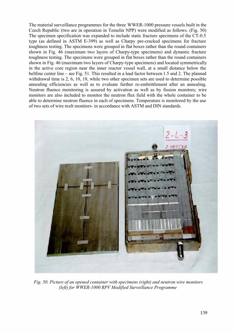
7/17/2019 IAEA 1556 Assessment and management of ageing of major nuclear power plant components important to safety …
http://slidepdf.com/reader/full/iaea-1556-assessment-and-management-of-ageing-of-major-nuclear-power-plant 149/215
The material surveillance programmes for the three WWER-1000 pressure vessels built in theCzech Republic (two are in operation in Temelin NPP) were modified as follows. (Fig. 50)The specimen specification was expanded to include static fracture specimens of the CT-0.5type (as defined in ASTM E-399) as well as Charpy pre-cracked specimens for fracturetoughness testing. The specimens were grouped in flat boxes rather than the round containersshown in Fig. 46 (maximum two layers of Charpy-type specimens) and dynamic fracture
toughness testing. The specimens were grouped in flat boxes rather than the round containersshown in Fig. 46 (maximum two layers of Charpy-type specimens) and located symmetricallyin the active core region near the inner reactor vessel wall, at a small distance below the
beltline center line – see Fig. 51. This resulted in a lead factor between 1.5 and 2. The plannedwithdrawal time is 2, 6, 10, 18, while two other specimen sets are used to determine possibleannealing efficiencies as well as to evaluate further re-embrittlement after an annealing.
Neutron fluence monitoring is assured by activation as well as by fission monitors; wiremonitors are also included to monitor the neutron flux field with the whole container to beable to determine neutron fluence in each of specimens. Temperature is monitored by the useof two sets of wire melt monitors- in accordance with ASTM and DIN standards.
Fig. 50. Picture of an opened container with specimens (right) and neutron wire monitors
(left) for WWER-1000 RPV Modified Surveillance Programme
139

7/17/2019 IAEA 1556 Assessment and management of ageing of major nuclear power plant components important to safety …
http://slidepdf.com/reader/full/iaea-1556-assessment-and-management-of-ageing-of-major-nuclear-power-plant 150/215
A new WWER-1000 surveillance programme was developed in Russia for new WWERs.Main features of this programme are the following:
- Surveillance specimens are compiled into flat containers;
- Irradiated container assemblies are located at the inner surface of RPV;
- Leading factor does not exceed 2;- Non-uniformity of neutron flax within container does not exceed 20%;
- Specimens for direct fracture toughness Determination are implemented(CT 0.5 specimens).
Fig. 51. New WWER surveillance programme.
140

7/17/2019 IAEA 1556 Assessment and management of ageing of major nuclear power plant components important to safety …
http://slidepdf.com/reader/full/iaea-1556-assessment-and-management-of-ageing-of-major-nuclear-power-plant 151/215
Destructive examinations
For some WWER-440 type 230 reactors, the initial ductile to brittle transition temperatureTk0, as well as the exact chemical composition (phosphorus and copper content) in the weldmetal was not measured. Thus, removing material (boat samples) from the pressure vessel is a
potential way to obtain these data. However, some problems are connected with such a
procedure, mainly:- it cannot be used for sampling a stainless steel clad vessel from the inside,
- the weld metal is usually covered by a protective surface layer of low-carbon steelelectrode material with a thickness up to 5 mm; the surface part of the sample,therefore, must not represent the real weld metal,
- sample dimensions are limited by the lowest allowable wall thickness; therefore,specimens for mechanical testing must be of a subsize type, thus necessitating thedevelopment of correlations between standard and subsize Charpy type specimens.
- sampling of the outer surface of the RPV is difficult because of the approximately 40
mm gap between the vessel and the water tank that provides biological shielding.The following activities were performed in Russia for WWER-440/230 RPVs irradiationembrittlement monitoring:
- taking boat samples (templates) and investigating materials with the use of sub-sizespecimens ;
- sampling and testing of trepans from Novovoronezh 2 (correlation between sub-sizeand standard Charpy results
- template irradiation in surveillance channels of WWER-440/213;
- development of new model of re-irradiation embrittlement.
The following problems were solved by using templates:
- Assessment of initial ductile-to-brittle transition temperature TK0
with the use of
special heat treatment (initial temperature TK0
was not determined by the
manufacturer );
- Determination of weld metal chemical composition (chemical composition was notdetermined by the manufacturer);
- Experimental determination of neutron fluence (validation of calculations);
- Determination of ductile-to-brittle transition temperature TK ( after annealing, currentvalue );
- Validation of annealing procedure ;
- Improvement of knowledge on re-embrittlement after annealing;
- Development of a new model of re-irradiation embrittlement (lateral shift approach).
Scheme of templates cut out from Novovoronezh-4 RPV is presented on Fig. 52.
141

7/17/2019 IAEA 1556 Assessment and management of ageing of major nuclear power plant components important to safety …
http://slidepdf.com/reader/full/iaea-1556-assessment-and-management-of-ageing-of-major-nuclear-power-plant 152/215
Fig. 52. Scheme of templets cut out from Novovoronezh-4 RPV.
The phosphorus contamination in the weld metal as well as the mechanical properties of theweld metal vary across the RPV wall thickness. (The phosphorus concentration is somewhathigher near the surface due to geometry and solidification effects.) Therefore, it is difficult todecide whether the surface samples provide a conservative or non-conservative estimate ofthe material properties across the vessel wall thickness. Nevertheless, boat samples have beenremoved from unclad vessel inner surfaces, namely in Kozloduy Units 1 and 2,
Novovoronezh Units 3 and 4, and Greifswald Units 1 and 2. The chemistry of the templatestaken from the inside surfaces of the Novovoronezh Unit 3 and Kozloduy Unit 2 RPVs didnot show any noticeable variation of chemical composition in the depth direction of the weld.Also, scrape samples were taken from the Kola Units 1 and 2 and Kozloduy Unit 1 RPVinside surfaces for chemical analysis. The measurements on these samples have been reportedto be reliable.
Scrapes for chemical analysis were also taken from the outside of the clad vessels at BohuniceUnits 1 and 2. However, due to a protective layer of undefined thickness, even a second andthird sampling in the same position might contain a small amount of the low carbon steelcover layer. Recently, small boat samples were also removed from the Bohunice outersurfaces. No samples were taken from other clad vessels of this type.
Sampling from the inside of unclad vessels is a very promising method for measuring theresidual transition temperature shift (ΔRT NDT) after annealing. Even though subsizespecimens must be used, the effectiveness of the annealing can be evaluated with a highdegree of reliability using correlations between subsized and normal specimens. This methodhas been used in several RPVs after annealing - e.g. Novovoronezh Units 3 and 4, KozloduyUnit 2, and Greifswald Units 1 and 2. The method has also been used for assessment of the re-embrittlement rate in service, for example, at Kozolduy Unit 1.
5.3.5 IAEA RPV surveillance database
The IAEA International Working Group on Lifetime Management of NPPs started thecreation of a worldwide database which would store the results from the RPV surveillance
programmes. The primary purpose shall be to collect all accessible data from these
142

7/17/2019 IAEA 1556 Assessment and management of ageing of major nuclear power plant components important to safety …
http://slidepdf.com/reader/full/iaea-1556-assessment-and-management-of-ageing-of-major-nuclear-power-plant 153/215
programmes and specimens and then perform a more general analysis of these results than can be performed using national (or utility) databases, only. The RPV fabrication techniques(including different source of metallic charges etc.) are slightly different in some countries,even though the manufacturing is performed according to the same standards and generalrequirements. As a result, vessels from each of the manufacturers represent a family, whichcan be slightly different from the others. Thus, results from one database may not be fully
applicable to RPVs from other manufacturers. Creation of this database started in 1996 underthe coordination of the aforementioned International Working Group on LifetimeManagement of Nuclear Power Plants. Up to now, results from surveillance programmes from10 countries are included in this database.
The first use of this database is included in the IAEA Co-ordinated Research Project (CRP)on “Evaluation of Radiation Damage of WWER RPV Using the IAEA Database on RPVMaterials” with the main goal to preparation of “Guidelines for Prediction of RadiationEmbrittlement of Operating WWER-440 Reactor Pressure Vessels”. [132]
Additionally, this database has also a second part that collects data from all IAEA Co-
ordinated Research Projects in the field of radiation damage in RPV materials, mainly:
- CRP-1 on "Irradiation Embrittlement of Reactor Pressure Vessel Steels" [133]
- CRP-2 on "Analysis of the Behaviour of Advanced Reactor Pressure Vessel Steelsunder Neutron Irradiation" [134]
- CRP-3 on “Optimising Reactor Pressure Vessel Surveillance Programmes and theirAnalysis” [135]
- CRP-4 on "Assuring Structural Integrity of Reactor Pressure Vessels" [136]
- CRP-5 on “Surveillance Programmes Results Application to RPV IntegrityAssessment” [137, 138]
- CRP on “Nickel Effects in Radiation Embrittlement of RPV Materials” [139]
- Round-robin Exercise (RRE) on “WWER-440 RPV Weld Metal IrradiationEmbrittlement, Annealing and Re-embrittlement”
Access to both parts of databases is controlled by agreement with the IAEA.
5.3.6 Requirements in Japan
Two relevant industrial technical standards, JEAC 4201-2000 and JEAC 4206-2000 were published in 1992 by the Japan Electric Association [140, 45].
JEAC 4201-2000 prescribes the reactor vessel material surveillance programme which is based on NRC 10 CFR Part 50 Appendix G (1995) and Appendix H (1995), and ASTME185-94; it also includes the Japanese embrittlement predictive equation which is mentionedin Section 6.1.5.
JEAC 4206-2000 provides experimental methods to confirm the integrity of nuclear power plant components against non-ductile failure. These methods include the linear elastic fracturemechanics analysis method and the PTS evaluation method. JEAC4206 is based on NRC 10
143

7/17/2019 IAEA 1556 Assessment and management of ageing of major nuclear power plant components important to safety …
http://slidepdf.com/reader/full/iaea-1556-assessment-and-management-of-ageing-of-major-nuclear-power-plant 154/215
CFR Part 50 Appendix G (1995) and Appendix H (1995), and the ASME Boiler and PressureVessel Code Section III.
5.4. TRANSIENT AND FATIGUE CYCLE MONITORING
5.4.1. Requirements in the USA
As discussed in Section 4.4, the only RPV components likely to experience significant fatiguedamage are the RPV studs. However, fatigue can become a significant degradationmechanism if indications or flaws are detected during the RPV ISI or if consideration is givento extending the operating life of the plant. In the former case, fatigue crack growth becomesimportant in the assessment and management of the ageing of PWR RPVs. In the latter case,fatigue cycles and loading to address Miner's Rule becomes important. In either case,transient and fatigue cycle monitoring is required..
5.4.2. Requirements in Germany
All German PWRs in operation are equipped with a fatigue monitoring system. On the basisof a plant specific weak point analysis of the NSSS, parameters to be monitored are definedand reported in a fatigue manual. Special emphasis is given to thermal loads such as thermalshocks, thermal stratification, and turbulent mixing phenomena which may occur very locally.These transients have been measured by means of special purpose instrumentation.(Thermocouples were installed on selected cross sections of interest.) In addition, global
parameters such as internal pressure, fluid temperature, mass flow, water level, etc., have beenmeasured via existing instrumentation and the data combined with the local parameters.
KTA 3201.4 contains requirements for recurring inspections. Parameters, which affect thefatigue life must be monitored and the resulting fatigue compared to the design margins.Sophisticated software packages are available to recognize fatigue relevant loadings and to
perform automatic fatigue evaluations. Thus the software tools not only satisfy the Coderequirements but establish a data base for a reliable evaluation of the fatigue status, end of life
predictions, or even life extension evaluations. Also, the German Reactor Safety Commissionrecommends that the fatigue status of every plant be updated after every 10 years of plantoperation. The fatigue status and forecast have to be reported within the safety status report to
be presented by the utility.
With respect to the RPV this means that the parameters to be monitored include: internal pressure, inlet and outlet loop temperature, and pressure vessel head temperatures at variouslocations on the outside surface. The reactor power is also monitored. In order to define the
actual service condition several other parameters are made available. Following this way, theRPV nozzles, the flange and bolt connections and the RPV head are also monitored.
5.4.3. French requirements and practices
Electricité de France (EDF) implemented a procedure called “transient bookkeeping” whenthey began operation of their first PWRs and now have a database covering more than 540reactor-years [141]. This procedure meets a regulatory requirement in the decree of February26, 1974 and has allowed EDF to confirm that their operating transients are less severe thantheir design transients. EDF is now studying an automatic device to book-keep complextransients in some nozzles (like charging line or steam generator feedwater nozzles); the
general book-keeping of transients, needed for RPV (and all class 1 components) fatigueevaluation, remains a manual procedure done by operators of each plant.
144

7/17/2019 IAEA 1556 Assessment and management of ageing of major nuclear power plant components important to safety …
http://slidepdf.com/reader/full/iaea-1556-assessment-and-management-of-ageing-of-major-nuclear-power-plant 155/215
Transient bookkeeping relies on the information collected by the units operating sensors: primary loop temperatures, primary and secondary pressures, auxiliary line temperatures, andin addition some logic signals (valve positions, etc.). Approximately 40 parameters aremeasured and recorded at a 4-loop PWR. Instrumentation has not been installed to measurelocal phenomena such as flow stratifications; however, transfer functions have beendeveloped to estimate the fatigue associated with such phenomena. The threshold values for
calculating fatigue usage are a change in:
- primary loop temperature: 5°C in 3 hours
- primary pressure: 1 MPa
- secondary pressure: 0.5 MPa
- auxiliary circuit temperature: 20° at 40°C/hour
These thresholds have been estimated very conservatively. The calculations show that for
transients equivalent to the detection threshold, the calculated stress variations are far belowthe endurance limit for the most heavily loaded areas of the main primary system [142].
When a transient is detected, the design Transient File is inspected to find “an enveloptransient,” i.e. a transient at least as severe in terms of its contribution to fatigue. It may ormay not be a transient of the same functional nature. In general, the operator looks for atransient of the same functional nature and then he checks the “envelope” character bycomparing the amplitudes and rate of change of the various parameters [143]. Should thisapproach fail, the operator will have to develop a new category for the transient file. Eachtransient event is added to the number of previous events and compared with the designlimits. Each year a balance sheet of all the transient consumptions is prepared to assure that
the overall fatigue usage is acceptable for all Class 1 components.
145

7/17/2019 IAEA 1556 Assessment and management of ageing of major nuclear power plant components important to safety …
http://slidepdf.com/reader/full/iaea-1556-assessment-and-management-of-ageing-of-major-nuclear-power-plant 156/215
6. AGEING ASSESSMENT METHOD
6.1. RADIATION EMBRITTLEMENT ASSESSMENT METHOD
6.1.1. Radiation embrittlement assessment methods in the USA
The rules for the assessment of radiation embrittlement in the USA are given in 10 CFR Part50, Appendices G and H. Appendix G [21, 22], “Fracture Toughness Requirements” specifiesfracture toughness requirements for ferritic materials in the RPV. Appendix H, “ ReactorVessel Material Surveillance Program Requirements”, provides the rules for monitoring thechanges in the fracture toughness properties of the RPV beltline materials due to irradiationembrittlement using a surveillance programme.
Appendix G refers to RT NDT, the nil-ductility temperature as the reference temperature of theRPV material for all conditions. The initial RT NDT for the unirradiated material is defined in
NB - 2331 of Section III of the ASME Code [7]. If the measured values (NDT by drop weighttest and the 50 ft-lbs (68 J) temperature) required to determine the initial RT NDT,
NUREG - 800, “Standard Review Plan” provides a method to for calculating an acceptableestimation of RT NDT.
As state above, Appendix H provides the rules for monitoring the changes in the fracturetoughness properties of the RPV beltline materials due to irradiation embrittlement using asurveillance programme. Appendix H refers to ASTM Standard E 185, ”Standard Practice forLight - Water Cooled Nuclear Power Reactor Vessels”. Appendix H requires that forsurveillance capsule withdrawal, the test procedures and reporting requirements must meet therequirements given in E 185 - 82 to the extent practicable. Recently, ASTM Committee E 10 -on Nuclear Technology and Applications published revisions to Standard E 185. A newstandard E 185, “Standard Practice for Design of Surveillance Programs for Light-Water
Moderated Nuclear Power Reactor Vessels” is now published in Volume 03.01, 2004 AnnualBook of ASTM Standards. E 185 - 04 covers procedures for designing a surveillance programme. A second standard, ASTM E 2215, “Standard Practice for the Evaluation ofSurveillance Capsules from Light-Water Moderated Nuclear Power Reactor Vessels”, is now
published in Volume 03.01, 2004 Annual Book of Standards. E 2215 - 04 provides the utilitythe option of performing fracture toughness testing in accordance with ASTM E 1820,“Standard Test Method for Measure of Fracture Toughness” and ASTM E 1921, “TestMethod for Determination of Reference Temperature, T0, for Ferritic Steels in the TransitionRange” [41].
General Criterion 31 of Appendix A to 10 CFR Part 50 requires that the NPP design reflect
the uncertainties in determining the effects of irradiation on material properties. Appendices Gand H which implement, in part Criterion 31, necessitate the calculation of changes in fracturetoughness of reactor vessel materials by radiation embrittlement throughout the service life.The calculation procedures to meet the intent of Criterion 31 are given in Regulatory Guide(R.G.) 1.99, Revision 2 [127]. Appendix G, 10 CFR Part 50 provides the calculation
procedures to estimate RTPTS throughout the service of the RPV. The calculation proceduresfor RTPTS are similar but are not the same calculation procedures given in R.G. 1.99,Revision 2.
In summary, radiation embrittlement assessment methods in the USA requires utilization of10 CFR Part 50 Appendices G and H, ASTM Standard 185 - 82, and R.G. 1.99 Revision 2.
146

7/17/2019 IAEA 1556 Assessment and management of ageing of major nuclear power plant components important to safety …
http://slidepdf.com/reader/full/iaea-1556-assessment-and-management-of-ageing-of-major-nuclear-power-plant 157/215
The RT NDT increases as the material is exposed to fast-neutron radiation. To find the mostlimiting RT NDT at any time period in the reactor’s life, the ΔRT NDT due to the radiationexposure associated with that time period must be added to the original unirradiated RT NDT.The extent of the shift in RT NDT is enhanced by certain chemical elements (such as copper andnickel) present in reactor vessel steels. Regulatory Guide 1.99, Revision 2 is used for thecalculation of RT NDT values in the beltline region as follows:
RT NDT = Initial RT NDT + ΔRT NDT + Margin (42)
The initial RT NDT is the reference temperature for the unirradiated material as defined in paragraph NB-2331 of Section III of the ASME Boiler and Pressure Vessel Code. If measuredvalues of initial RT NDT for the material in question are not available, generic mean values forthat class of material may be used if there are sufficient test results to establish a mean andstandard deviation for the class. The margin term accounts for the uncertainty in the initialRT NDT and scatter in the data used to estimate ΔRT NDT.
ΔRT NDT is the mean value of the adjustment in reference temperature caused by irradiationand should be calculated as follows:
ΔRT NDT = [CF]f (0.28-0.10 log f) (43)
where CF is a chemistry factor which is a function of copper and nickel content, f is thefluence in 1023n/m2, and ΔRT NDT has units of Fahrenheit degrees [127].
Master Curve methodology is gaining acceptance throughout the world as an alternative to theRG 1.99, Revision 2 and ASME Code methodology for determining the fracture toughness.However, the validity of the Master Curve methodology (ASTM E 1921) is now in question
based upon recent findings at the Oak Ridge National Laboratories (ORNL). The recentresults from ORNL are discussed at the end of this Section. In the Master Curve methodology
materials are tested in accordance with the test standard ASTM E 1921-97 [144]. This testmethod determines a reference temperature, T0, which characterizes the fracture toughness offerritic steels that experience onset of cleavage cracking at elastic, or elastic-plasticinstabilities. Since low alloy RPV steels behave in this manner, the Master Curvemethodology is applicable to low alloy RPV steels. ASME Code Cases N-629 and N-631define a reference temperature, RTTO, which may be used as an alternative to the indexingreference temperature , RT NDT. These code cases indicate define RTT0 as:
RTT0 = T0+35oF (44)
This relationship between RTTO and To value was proposed by the ASME task group in orderto maintain consistency with the ASME current licensing basis [145]. This 35ºF value was
determined as the appropriate add-on to be applied to make RTT0 an acceptable replacementof RT NDT. This value also adequately bounded the data from plate HSST02 that is the lowestdata in the original K IC ASME database.
The Master Curve methodology has been utilized in the USA to determine the Initial RT NDT and the ΔRT NDT. When the Master Curve methodology was utilized in RPV safetyassessments, additional margins were added to account for uncertainties between the materialthat was tested, the materials in the RPV and bias in the test data. The NRC evaluation ofthese uncertainties is described in a May 1, 2001 letter to M. Reddemann from J. G. Lamb(This document may be retrieved from the NRC Web-Site using ADAMS Accession No.ML011210180). J.G. Lamb’s letter discussed in part the determination of the Initial RT NDT and the ΔRT NDT of materials tested as part of the Kewaunee Nuclear Power Plant Surveillance
147

7/17/2019 IAEA 1556 Assessment and management of ageing of major nuclear power plant components important to safety …
http://slidepdf.com/reader/full/iaea-1556-assessment-and-management-of-ageing-of-major-nuclear-power-plant 158/215
Capsule Program. As part of the Kewaunee data and acquisition programme, a secondsurveillance capsule has been tested. The NRC is currently reviewing the new data and their
position on the uncertainties of use of the Master Curve methodology will be published in thenear future.
ORNL recently published two reports [146] and [147] that providing test results that showed
T0 obtained from testing of PCVN specimens versus T0 determined from 1 CT specimens hada disparity of 21 °C. Thus, the question of specimen size as well as geometry becomes anuncertainty.
6.1.2. Radiation embrittlement assessment methods in Germany
The German Nuclear Safety Standards KTA 3201.2 [148] and KTA 3203 [149] require thatthe USE must remain above 68 J (50 ft-lb) during operation. If a USE value of more than orequal to 68 J cannot be proven by the surveillance programme, further measures have to beundertaken to confirm the safety of the RPV. Such measures shall be defined in accordancewith the authorized expert.
The fracture toughness during operation is determined by use of the adjusted referencetemperature. The procedure to calculate the fracture toughness curve is given in the KTA3201.2. The determination of the adjusted reference temperature itself is described in the KTA3203. The adjusted reference temperature may be determined either according to the referencetemperature RT NDT concept or the Master Curve concept.
Up to a fluence of 1 × 10²³ n/m², a fixed value of 40 K may be used as adjusted referencetemperature for the materials where no data from surveillance sets are available. For fluencesof more than 1 x 10²³ n/m², the value for the limiting adjusted reference temperature given byKTA 3203 must be proven by surveillance data for all beltline materials from the sets as
required in KTA 3203 (see Fig. 41-43 in page 136-138).
6.1.3. Radiation embrittlement assessment methods in France
The French requirements are specified in the 1974 Order and the corresponding rules are presented in RCC-M “Design and Construction Rules for the Mechanical Components ofPWR Nuclear Islands” [24, 27] and RSE-M “In-service Inspection Rules for the MechanicalComponents of PWR Nuclear Islands” [28, 29] .
Using the surveillance programme results a new shift formula has been proposed for welded joins:
ΔRT NDT (°C) = (8+(24+1537(P-0.008)+238(Cu-0.08)+191 Ni2(Cu))f 0.35 for base metal (45a)
ΔRT NDT (°C) = (22+(13+823(P)+148(Cu-0.08)+157 Ni2(Cu))f 0.45 for welded joins (45b)
ΔRT NDT(°C)=(8+(24+1537(P-0.008)+238(Cu-0.08)+191 Ni2(Cu))f 0.35 (46)
where
P is the weight % phosphorus, Cu is the weight % copper, Ni is the weight % nickel, and f isfluence in 1023 n/m2. This equation was specifically developed for the French RPV materialand is based on a large number of measurements. Note that this formula is different from the
equation specified in USNRC Regulatory Guide 1.99, Rev. 2, and shown above as
148

7/17/2019 IAEA 1556 Assessment and management of ageing of major nuclear power plant components important to safety …
http://slidepdf.com/reader/full/iaea-1556-assessment-and-management-of-ageing-of-major-nuclear-power-plant 159/215
Equation 25. Changes in both base and weld metal reference nil-ductility transitiontemperatures calculated with Equation 46 are compared with measurements in Fig. 53. Onlyfour measured values of ΔRT NDT out of 150 measurements exceed the predicted values lessthan 10 °C, which suggest that the correlation is conservative.
Fig. 53 Comparison of measured and calculated RT NDT shifts in French RPV steel.
6.1.4. WWER radiation embrittlement assessment methods
Even though most of the WWER reactors, including the WWER-1000 and the WWER-440/V
213 types, have RPV surveillance specimen programmes, the Soviet Code [36] is based on
149

7/17/2019 IAEA 1556 Assessment and management of ageing of major nuclear power plant components important to safety …
http://slidepdf.com/reader/full/iaea-1556-assessment-and-management-of-ageing-of-major-nuclear-power-plant 160/215
calculations. The primary reason for this is because the Code was prepared for RPV design,rather than plant operation. The WWER design basis is discussed in Section 3.5 of this report.Section 3.5.3 discusses the stress analysis procedures including stress categories, stressintensity limits, areas of the RPV to be analysed, and stress analysis methods. Section 3.5.4discusses design and analysis against brittle fracture including the allowable fracturetoughness, postulated defects, stress intensity factors, and transition temperatures and
temperature shifts.
There is no valid procedure in Russian codes for the evaluation of surveillance specimen testdata and their application to RPV integrity.
The following approach is used in the: VERLIFE [42] Procedure:
Two equivalent approaches are given :
(a) based on the “Master Curve” approach
- transition temperature T0 is determined in accordance with the [144] for the fluenceas close to the calculated fluence for the RPV state under assessment,
- the standard deviation σ of the estimate of T0 is given by [144]:
σ1 = β / N0.5 (oC) (47)
Where
N = total number of specimens used to establish the value of T0,
β = + 18 oC.
T0 consider the scatter in the materials, another margin denoted in what follows ΔTM should be applied. If this value is not available the application of the following values issuggested
ΔTM = 10°C for the base material, (48)
ΔTM = 16°C for weld metals.
The resulting margin is:
σ=(σ12
+ΔTM2
)1/2
(49)
The reference temperature used in integrity evaluation, RT0, is defined as:
RT0 = T0 + σ (50)
(b) based on the transition temperature approach
- The change in the transition temperature is measured using both Charpy V-notchimpact and static fracture toughness tests. The shift in the transition temperature isthen compared to the value calculated using the AF coefficient in the code.
150

7/17/2019 IAEA 1556 Assessment and management of ageing of major nuclear power plant components important to safety …
http://slidepdf.com/reader/full/iaea-1556-assessment-and-management-of-ageing-of-major-nuclear-power-plant 161/215
- However, a new radiation embrittlement trend curve for a given RPV material can beconstructed if values from at least three different neutron fluences are obtained andstatistically evaluated. The mean trend curve should be vertically shifted upward bythe value of ΔTM in accordance with the relation (48). If any experimental pointexceeds this adjusted trend curve, the curve should be shifted further until it boundsall data. This upper boundary of the shifts is to be used in assessment of RPV
resistance against fast fracture.
- This overall approach is consistent with the definition of the AF coefficient as theupper bound value of the experimental data.
- Extrapolation can be performed only for fluences not exceeding the maximumexperimental value by a factor of two.
Within the IAEA CRP on “Surveillance Programmes Results Application to RPV IntegrityAssessment”, guidelines for evaluation of surveillance test data and their application toWWER-440 RPVs are under preparation.
6.1.5 Radiation embrittlement assessment methods in Japan
Japanese assessment methods are specified in JEAC4201-2000 [140].
The document provides the Japanese embrittlement predictive equation which is slightlydifferent from the equations provided in R.G. 1.99, Rev. 2 [127] because it takes into accountJapanese experimental data.
ΔRT NDT is calculated as follows:
ΔRT NDT = [CF]f (0.29-0.04 log f) for base metal (51)
[CF]=-16 + 1,210 × P + 215 × Cu+77√Cu × Ni
ΔRT NDT = [CF]f (0.25-0.10 log f) for weld metal (52)
[CF]=26 - 24 × Si - 61 × Ni + 301√Cu × Ni
where Cu, Ni, P and Si are contents of copper, nickel, phosphorus and silicone, and “f “is thefluence in 1023n/m2, and ΔRT NDT has units of Celsius degrees [140].
To calculate ΔRT NDT at any depth (e.g., at 1/4 or 3/4 of the wall thickness), the followingformula is used first to attenuate the fluence at the specific depth:
f = f 0 (e-.24a/25.4) (53)
where a (in mm) is the depth into the vessel wall measured from the vessel clad/base metalinterface and f 0 is the fluence at RPV inner surface. The resultant fluence is then put intoEquation (51) along with the chemistry factor to calculate ΔRT NDT at the specific depth.
6.2. THERMAL AGEING ASSESSMENT METHODS
As discussed in Section 4.2, there is no evidence of a significant change in theΔRT NDT due to thermal embrittlement. Therefore, we do not recommend the use of anythermal ageing assessment methods.
151
7/17/2019 IAEA 1556 Assessment and management of ageing of major nuclear power plant components important to safety …
http://slidepdf.com/reader/full/iaea-1556-assessment-and-management-of-ageing-of-major-nuclear-power-plant 162/215
6.3. FATIGUE ASSESSMENT METHODS
6.3.1. Fatigue assessment in the United States of America
Crack initiation
Crack initiation is estimated by determining the fatigue usage at a specific location whichresults from either actual or design-basis cyclic loads. The time-to-initiation can be predictedonly if the applied load sequences and recurrence frequencies are known. If the cyclingloading is random, estimates of time to initiation are uncertain.
For a fatigue life evaluation, the data needed are the amplitude and number of stress cyclesexperienced during a given operating period and the amplitude and number of cycles that leadto crack initiation in laboratory specimens. The sum of the ratios of these quantities gives thecumulative fatigue usage factor. The best source of information for the relatively newer US
plants is the certified stress report and the design specification. The certified stress reportgives the design-basis cumulative usage factors for vessel components and the Code
allowable number of cycles for prescribed events.The fatigue usage factor is defined according to ASME Code requirements. This value mustnot exceed 1.0 during the design life of the component. With the conservatism inherent to thiscalculation, it is presumed that fatigue crack initiation can be prevented by ensuring that thefatigue usage factors remain below the limit of 1.0. The ASME Code fatigue design curvesare based on data from smooth-bars tested at room temperature in air. The ASME Codeapplies a factor of 2 on strain range and a factor of 20 on the number of cycles to the smooth-
bar data. The factor of 20 on cycles was intended to account for data scatter, size effect,surface finish and moderate environmental effects. However, current testing of fatiguespecimens in reactor coolant environment indicates that the factor of 2 on strain and 20 on
cycling may not be sufficient for all loading conditions.
Cyclic crack growth
Once a crack has initiated, either by fatigue or some other mechanism such as SCC, continuedapplication of cyclic stresses can produce subcritical crack growth. The Paris crack growthrelationship is used to calculate crack growth:
da/dN = C(ΔK)n (54)
where
da/dN = fatigue crack growth rate (distance/cycle);
ΔK = stress intensity factor range = (K max - K min);
C, n = constants, related to material and environment; and
K max, K min = maximum and minimum stress intensity factors during theloading cycle
Crack growth rates, such as those in the ASME Code, are not constant for all ranges of ΔK.There are three regimes. These are: crack growth at low, medium, and high ΔK values. Atvery low ΔK values, the growth rate diminishes rapidly to vanishingly low levels. A threshold
stress intensity factor range (ΔK th) is defined as that below which fatigue damage is highlyunlikely.
152

7/17/2019 IAEA 1556 Assessment and management of ageing of major nuclear power plant components important to safety …
http://slidepdf.com/reader/full/iaea-1556-assessment-and-management-of-ageing-of-major-nuclear-power-plant 163/215
At the high end of the ΔK range, crack growth increases at a faster rate. This acceleration is partially a result of the increasing size of the plastic zone at the crack tip, which has the effectof increasing the effective stress intensity factor range (ΔK eff ). In addition, as the maximumapplied stress K max approaches the critical applied stress intensity (K c), local crack instabilitiesoccur with increasing frequency. Increasing the R ratio (K min/K max) causes an increase incyclic crack growth rate.
Knowing the history of stress cycle events in conjunction with the appropriate crack growthcorrelations allows the prediction of crack growth rate in components. Furthermore,information in Section XI of the ASME Code on crack initiation and crack arrest fracturetoughness of low alloy steel can be used to calculate the critical crack size of the component,and thus time to failure, or residual life.
The preceding discussions are strictly valid only for metallurgically large cracks (in theliterature, the minimum size of a metallurgically large crack ranges from approximately0.0025 to 0.18 mm (0.0001 to 0.005 in.)). For short cracks (i.e., crack sizes comparable to thesize of the high stress field at the tip of the stress raiser at the crack initiation site), the
applicability of analyses based on LEFM tends to break down in some instances. Variousattempts have been made to address the growth rates of short cracks, but a universallyapplicable treatment has yet to be established. However, the inspections conducted inaccordance with the ASME Code are sufficient to detect crack growth before the acceptancecriteria are reached.
It should be noted that for indications found and sized during ISIs such that crack growthevaluation is required, LEFM-based crack growth procedures are adequate and sufficient.Very short cracks for which LEFM-based procedures are not applicable are within acceptancecriteria limits for size.
The crack size at the end of a prescribed period of operation can be determined if the cyclicloading sequence is known and a crack growth curve (da/dN versus ΔK), such as that inASME Section XI, Article A4300, is available.
Fatigue damage management programmes
For component locations and parts with no history of fatigue damage, the current ASMECode Section III, Subsection NB-3000 fatigue design basis can be shown to remain validthroughout the design life; in this case, the original design-basis transients. The total usagefactor must be shown to be valid, in terms of the numbers and severity of the loads, for anyextended operation and the calculated fatigue usage factor, including any modifications to thedesign-basis transients to account for actual plant operating transients not enveloped by theoriginal design-basis transients, must be shown to be less than unity. The Section III,Subsection NB fatigue evaluation procedures remain valid for these calculations. If the
projected fatigue usage factor for the extended operation exceeds unity, detailed fatiguereanalysis considering actual plant operating transients, including partial cycle counting, inlieu of the original assumed design-basis transients, may be used. The fatigue usage factorlimit for this reanalysis remains unity. The Section III, Subsection NB evaluation proceduresremain valid for these calculations.
For component locations and parts with a history of fatigue damage, or as an alternative tothe analytical verification of the adequacy of the original fatigue design basis throughout thedesign life, an effective in-service examination programme for managing the effects of
potentially significant fatigue damage is needed. Formal inservice examination requirements
153

7/17/2019 IAEA 1556 Assessment and management of ageing of major nuclear power plant components important to safety …
http://slidepdf.com/reader/full/iaea-1556-assessment-and-management-of-ageing-of-major-nuclear-power-plant 164/215
are provided for each plant in its plant ISI and Inservice Testing programmes and arereferenced to an applicable edition of the ASME Code Section XI Rules for ISI of NuclearPower Plant Components. The plant ISI programme, including any commitments to enhancedor augmented inspections as the result of plant operating experience or regulatoryenforcement and any special reassessments of loading and material conditions, provides anacceptable basis for continued operation of a component. The intervals for these
examinations, and the requirements for expansion of the number of locations examined ifflaws are detected, assure that significant undetected fatigue degradation of components willnot occur.
Fatigue reanalysis
If the confirmation of the current fatigue design basis for an extended operation is to bedemonstrated, the procedure to be followed is similar to that used during the initial plantdesign. During the design of plant components, in accordance with NB-3000, a set ofdesign-basis transients was defined. These design-basis transients, as described bytemperature, pressure, flow rate, and number of occurrences, were intended to conservatively
represent all transients expected during the design life of the plant. The plant TechnicalSpecifications require that major cycles be tracked during service, relative to actual operatingtransients, to assure satisfaction of fatigue design requirements. However, since details of theTechnical Specification transient tracking requirements vary widely from plant to plant, thedemonstration that the design-basis transients remain valid for any extended operation, suchthat the numbers and severity of actual operating transients remain enveloped, is a plant-specific consideration. A variety of methods are available for this demonstration. Theseinclude regrouping of design-basis transients, taking credit for partial (versus full) cycletransients, use of actual plant transients rather than design-basis transients, or using a moresophisticated cycle monitoring programme.
The second step in the fatigue design basis confirmation process is demonstrating that thefatigue usage factor calculated for the most critical component location or part remains belowunity, as determined by the use of the confirmed design-basis transients extended through theoperation. The fatigue analysis procedures of NB-3000 remain valid for these calculations.The ASME Section III rules require that fatigue usage factors calculated for this extended
period remain below unity. If this criterion is satisfied, the component is presumed safe (i.e.,no fatigue cracks have been initiated).
For components with a reasonably high degree of design margin of safety with regard tofatigue limits, acceptable results for extended life can be demonstrated by conservativeevaluation. For more limiting components, a conservative approach may project cumulative
fatigue usage factors which approach or exceed a value of 1.0. Unless the excessiveconservatism can be removed, more frequent ISIs may be required or, in the worst case,replacement or refurbishment may be recommended far too prematurely.
One way to remove conservatism is to refine the fatigue analysis. The methodology can beenhanced from simple elastic calculations to elastic-plastic or even fully plastic approaches.The definition of loading cycles can also be refined, including regrouping of design basistransients. Credit can be taken for partial versus full design basis transients. Actual plantloading cycles can be used instead of originally assumed design loading cycles. Thesealternative techniques can be implemented in a manner that is consistent with the ASMECode to show that fatigue damage accumulation will remain within established limits for any
extended operation.
154

7/17/2019 IAEA 1556 Assessment and management of ageing of major nuclear power plant components important to safety …
http://slidepdf.com/reader/full/iaea-1556-assessment-and-management-of-ageing-of-major-nuclear-power-plant 165/215
Finally, if a refined fatigue analysis is unable to show that the component will remain withinthe established limits, the component can be examined for detectable fatigue damage andrepaired, refurbished or replaced as appropriate.
Section 6.3.1 of the previous TECDOC 1120 indicated that for components, locations and
parts with a history of fatigue damage, or as an alternative to the analytical verification of the
adequacy of the original fatigue design basis throughout the design life, an effective in-serviceexamination programme for managing the effects of potentially significant fatigue damage isneeded. The NRC has not endorsed this alternative for extended NPP operation.
Additionally, for extended NPP operation, the NRC requires license renewal applicants toevaluate a sample of critical components, using correlations developed from fatigue testing inreactor coolant environments. NUREG/CR-6260 [150] identifies the minimum number ofcomponents selected for evaluation. Formulas for calculating the environmental lifecorrection factors are contained in NUREG/CR-6583 [151] for carbon and low alloy steelsand in NUREG/CR-5704 [152] for austenitic stainless steels.
6.3.2.
Fatigue assessments in GermanyThe procedure as described in the ASME Code for the assessment of crack initiation andcyclic crack growth is basis for the relevant stipulations in the German KTA 3201.2 [148].
6.3.3. Fatigue assessments in France
The RCC-M general rules [24] and (S,N) fatigue curves are similar to the ASME Section IIIB3000 rules. However, some specific rules have been developed and incorporated into RCC-M to analyse crack-like defects (RCC-M Appendix ZD), studs (use of experimental results),and plastified areas by Ke optimization, which are not in the ASME Code.
6.3.4.
WWER fatigue assessments
Fatigue evaluations
The peak stresses are the main concern in the WWER fatigue evaluations. The Code givesspecific rules for fatigue calculations and design curves for different materials as well asfatigue strength reduction factors for welded joints and for some operational factors such asradiation and corrosion.
Two methods are allowed in the Code for determining the fatigue:
(a) design curves for a rough estimate,
(b) design formulae for more detailed calculations or when the design curves cannot besatisfied.
Generally, the following safety factors are used:
- pressure vessel materials:
nσ = 2,
n N = 10
- bolting materials:
nσ = 1.5,
n N = 3
155

7/17/2019 IAEA 1556 Assessment and management of ageing of major nuclear power plant components important to safety …
http://slidepdf.com/reader/full/iaea-1556-assessment-and-management-of-ageing-of-major-nuclear-power-plant 166/215
where the factor nσ is applied to the stress and the factor n N is applied to the number of cyclesin the same manner as in the ASME Code. It must be noted that design curves as well asdesign formulae were constructed as lower boundaries of existed experimental data obtainedduring Qualification Programmes of RPV materials. Moreover, the coefficients φw ≤1 areincorporated into the calculational formulas. These coefficients conservatively adjust theformulas for the effects of the welded joints on the fatigue life. The stress and number of
cycle factors listed above are lower for the bolting materials than for the pressure vesselmaterials because the bolting is changed out periodically. Also, bolting failure should result inleakage rather than rupture.
Cumulative usage factors D are calculated using linear Miner’s law; the maximum allowablevalue is equal to one.
6.3.5 Fatigue assessment in Japan
General requirement
The fatigue evaluation method and (S,N) fatigue curves stipulated in the METI notification
No.501 [43] and JSME Code and Standards “Code for Design and Construction”, JSMESNA2-2002 [44] are similar to the ASME Section III B3000 rules.
Environmental f atigue evaluation
In September 2000, Japanese regulatory body, MITI (current METI), published a notificationwhich required electric utilities to perform fatigue evaluation for the plant life managementevaluation taking into account environmental effect.
The parameter for evaluating environmental effects is the fatigue life reduction factor forenvironmental effects, Fen. Fen represents the reduction in fatigue life resulting from the high-
temperature water LWR environment. As shown in Equation 55 below, Fen is defined as thefatigue life obtained from fatigue tests under room temperature in air, divided by the fatiguelife obtained from fatigue tests under high-temperature LWR water conditions with the samestrain amplitude.
W
Aen N
NF = (55)
where, NA is fatigue life under room-temperature atmosphere and Nw is fatigue life underwater environment.
The cumulative usage factor allowing for environmental effects, UFen, can beexpressed by the following equation, using Fen.
∑=
×=n
1ien,i FU
i
enUF (56)
Where Ui and Fen,i represent the cumulative usage factor and fatigue life reduction factor forenvironmental effects, respectively, for the i-th load set pair (individual transient cycleevaluations) among the n-number of load set pairs (all evaluated transient cycles).
In the above equation, Fen is calculated according the following two Fen equations for carbon
steel/ low alloy steel and for austenitic stainless steel. They are provided in the MITIenvironmental fatigue evaluation guideline.
156

7/17/2019 IAEA 1556 Assessment and management of ageing of major nuclear power plant components important to safety …
http://slidepdf.com/reader/full/iaea-1556-assessment-and-management-of-ageing-of-major-nuclear-power-plant 167/215
Fen for carbon steel/ low alloy steel:
0.777S17.23S*
0.5ppm)(DO3)ln(0.5/0.0O*
0.03ppm)(DO0O*
0.5ppm)DO(0.03)ln(DO/0.03O*
)180(T0.216*T
)180(T0.7396-T0.00531T*
sec)/%0004.0()0004.0ln(*c)0.0004%/se(1.0%/sec)ln(*
sec)/%0.1(0*
where
**S)112.0*O*T199.0()Fln( en
+×=
>=
<=
≤≤=
<=
≥×=
<ε=ε ≥ε≥ε=ε
>ε=ε
ε××+××−=
℃
℃
&&
&&&
&&
&
(57)
Fen for austenitic stainless steel:
℃
℃℃
℃
c)0.0004%/se(0.0004*
0.4%/sec)ec(0.0004%/s*
0.4%/sec)(0.4*
)325(25.0
)325T(1000.053-T109.33P
)100(T04.0
)4.0/*ln(233.1)ln(
4-
<=
≤≤=
≥=
≥=
<<××=
≤=
×−=
ε ε
ε ε ε
ε ε
ε
&&
&&&
&&
&
T P
P
where
P F en
(58)
*ε & is strain rate-dependent parameter, T* is temperature-dependent factor and O*is dissolvedoxygen dependent factor.
The MITI environmental fatigue evaluation guideline mentions that these two equations wereacquired from experiment data of PWR coolant environment (DO≤0.005 ppm). Fen for BWRcoolant environment (DO>0.005 ppm) is under preparation. It is possible to apply the abovetwo Fen equations to BWR coolant environment but evaluation results could be a little tooconservative.
The MITI environmental fatigue evaluation guideline does not specify a detailed evaluation procedure for evaluating actual plant conditions. “Guidelines on Environmental FatigueEvaluation for LWR Component” [153] published by Thermal and Nuclear PowerEngineering Society in June 2002 provides a detailed procedure and specific and practicaltechniques. The document is used as a guidance documents for evaluating environmentalfatigue for LWR components.
6.4. ASSESSMENT METHODS FOR PWSCC OF ALLOY 600 COMPONENTS
6.4.1. PWSCC assessments in the USA
Section 6.4 of the previous TECDOC 1120 indicated PWSCC crack growth can be calculatedwith the following empirical equation developed by Scott [154]:
157

7/17/2019 IAEA 1556 Assessment and management of ageing of major nuclear power plant components important to safety …
http://slidepdf.com/reader/full/iaea-1556-assessment-and-management-of-ageing-of-major-nuclear-power-plant 168/215
da/dt = 2.56e-(33,000/RT) (K I - 9)1.16 (59)
where da/dt is the PWSCC growth rate, K I is a crack tip stress intensity factor in MPa m1/2, Tis temperature in degrees kelvin, and R is the universal gas constant. This model wasdeveloped by Scott using data obtained by Smialowski et al. of Ohio State University.
The EPRI PWR Materials Reliability Program (MRP) has compiled an extensive database ofcrack growth rates on thick-section Alloy 600 materials [155]. Using this data, the MRP,derived the following crack growth rate model at 325°C (617 ° F):
da/dt = 1.67 x 10⁻¹² (K I – 9)1.16 m/s (60)
The MRP and Scott curves are relatively in close agreement, with the Scott curves beinglower. It should be noted that the above equations imply a threshold for crackingsusceptibility, K ISCC = 9 MPa m1/2. This involves assumptions not currently substantiated byactual crack growth rate data for Alloy 600 materials, since no test results for thick-walledmaterials are available for K values less than about 15 MPa m1/2.
6.4.2. PWSCC assessment in France
Between 1991 and 1996, 52 vessel heads have been periodically inspected by contact eddycurrent [83]. 27 penetrations have been used to derive a crack growth law from 180 fieldcracks. [156]. Results are coming from hot dome at 300°C and cold dome at 290°C. Anactivation energy of 130 KJ/mole has been used. two laws are derived from this fieldexperience:
- mean curve at 290°C :
da/dt = 0.03 (K-9)0.52
(61)
- upper bound at 290°C :
da/dt = 0.3 (K-9)0.10 (62)
with da/dt in μm/h and K in MPa m0.5.
Fig. 54 presents the variation of crack growth rate with dome temperatures, the temperatureeffect of 30°C difference, is in the scatter band of the result data.
Fig. 55 presents a comparison of field data and laboratory results that confirm the validity ofour proposed equations.
A complementary programme is going on to evaluate the crack growth rate in weld material[83, 156].
158

7/17/2019 IAEA 1556 Assessment and management of ageing of major nuclear power plant components important to safety …
http://slidepdf.com/reader/full/iaea-1556-assessment-and-management-of-ageing-of-major-nuclear-power-plant 169/215
Fig. 54. Comparison of alloy 600 crack growth rate for hot and cold dome of similar plants
(reduced at 290°C with Q=130 KJ:mole).
A complementary programme is going on to evaluate the crack growth rate in weld material[156, 157].
Last results confirm that:
- alloy 182 is susceptible to stress corrosion cracking in PWR primary water, only if theapplied total stress exceeds the yield stress
- Fig. 56 presents results obtained under load control between 300 and 600 MPa at threedifferent temperatures (330°C, 350°C and 360°C). The results are presented in term oftrue stress versus time after conversion to the 325°C temperature using an activationenergy of 185 kJ/mole
- the stress corrosion cracking threshold is greater for alloy 182 than for alloy 600
- the stress relieve is an important beneficial aspect (all locations in French plantsexcept CRDM nozzle and SG stub weld)
- comparison of results on alloy 182 and alloy 600 shows:
o the same effects of parameters are observed for temperature, stress intensityfactor and cold work effects,
o specific effects have been observed on alloy 182 for heat treatment, dendriteorientation, heat to heat variation
- the crack growth rate obtains on alloy 182 is in the scatter band of results on alloy
600 and field data, see Fig. 57.
159

7/17/2019 IAEA 1556 Assessment and management of ageing of major nuclear power plant components important to safety …
http://slidepdf.com/reader/full/iaea-1556-assessment-and-management-of-ageing-of-major-nuclear-power-plant 170/215
Fig. 55. Comparison of field and laboratory crack growth rate data obtained on alloy 600
(reduced at 290°C with Q=130KJ:mole).
Fig. 56. Crack initiation time versus stress for alloy 182 at 325°C (Q=185kJ/mole).
160

7/17/2019 IAEA 1556 Assessment and management of ageing of major nuclear power plant components important to safety …
http://slidepdf.com/reader/full/iaea-1556-assessment-and-management-of-ageing-of-major-nuclear-power-plant 171/215
Fig. 57. Comparison of crack growth rates measured in alloys 182 and alloy 600.
6.5. ASSESSMENT METHODS FOR RPV CLOSURE HEAD STUD STRESS
CORROSION CRACKING
Once SCC is suspected, detection and sizing of any cracks are required for determining theeffects on the RPV closure head studs. ISI by volumetric means, such as ultrasonic testing
(UT) is the only way to size SCC indications. Visual examination or dye-penetrant methodsmay detect SCC flaws but these techniques can only measure the length of the flaw on thesurface.
Once flaws are detected and sized in RPV components such as closure head studs, analyticalevaluation utilizing fracture mechanics is required to predict life remaining after the initiationof the detected flaw. As with the age related degradation mechanism fatigue, the sub-criticalcrack growth must be determined to assess and manage SCC in RPV components.
As discussed in Section 3, the ASME Boiler and Pressure Vessel Code, Section XI, AppendixA provides an analytical technique for assessing crack growth during the application of cyclic
stresses. However, SCC being corrosion driven does not require cyclic loading for the SCCinitiation flaw to grow. Therefore, information is required in terms of delta "a" versus delta "t"(da/dt. change in crack length with time).
In summary, volumetric ISI in conjunction with an analytical evaluation is a requirement forthe assessment and management of SCC in the PWR RPV.
6.6. ASSESSMENT METHODS FOR BORIC ACID CORROSION
Section 6.6 of the previous IAEA-TECDOC-1120 indicated:
Boric acid corrosion due to leaking reactor coolant has resulted in wastage of the low alloysteels of the RPV flanges, top closure heads, and RPV studs at a rate of approximately
161

7/17/2019 IAEA 1556 Assessment and management of ageing of major nuclear power plant components important to safety …
http://slidepdf.com/reader/full/iaea-1556-assessment-and-management-of-ageing-of-major-nuclear-power-plant 172/215
25 mm/year. Once a boric acid leak is detected, the wastage level of the given ferritic steelcomponent must be determined. An assessment must be made to determine if the minimumdesign thicknesses for the given component have been violated. If the wasted componentdesign thickness is violated, refurbishment by welding may be required. If the component'sdesign thickness is marginal following detection of boric acid attack, an analytical evaluationis required to assess the component's "fit for service" status.
The rate of boric acid corrosion wastage of the low alloy steel is dependent upon thetemperature of the boric acid and the concentration of oxygen and corrosive elements in the
boric acid. EPRI in [158] reported corrosion rates for low alloy steel in oxygenated reactorcoolant at rates exceeding 25 mm/year.
6.7. FLAW ASSESSMENT METHODS
6.7.1. Flaw assessment methods in the USA
Article IWA-3000, "Standards for Examination Evaluation", requires evaluation of flaws
detected during the inservice examination. The acceptance standards for flaws detected duringthe ISI are given in IWB-3500, "Acceptance Standards'". Flaws that exceed the allowableindication standards of IWB-3500 can be analysed in accordance with Appendix A "Analysisof Flaws" [159] to determine their acceptability. Appendix A to Section XI uses a procedure
based upon the principles of LEFM for analysis of flaw indications detected during ISI. WhileSection III is a construction code, Section XI provides rules for the integrity of the structureduring its service life. The concepts introduced in Appendix G to Section III are carried overto Appendix A to Section XI. Figure 58 shows the functional organization of ASME SectionXI. The evaluation procedure can be summarized as follows: set up a simplified model of theobserved flaw, calculate stress intensity factors, determine appropriate material properties,determine critical flaw parameters and apply acceptability criteria to the critical flaw
parameters.
Fig. 58. Functional organization of ASME section XI in-service inspection documents.
162

7/17/2019 IAEA 1556 Assessment and management of ageing of major nuclear power plant components important to safety …
http://slidepdf.com/reader/full/iaea-1556-assessment-and-management-of-ageing-of-major-nuclear-power-plant 173/215
Models for flaw analysis are given in A-2000 of Appendix A. Definitions are given coveringflaw shape, proximity to closest flaw, orientation and flaw location to permit their applicationinto an analytical model for LEFM.
Methods for K I determination are given in A-3000 of Appendix A. Article A-3000 defineshow the applied stresses at the flaw location can be resolved into membrane and bending
stresses with respect to the wall thickness and presents a stress intensity factor expression forthe flaw model.
Article A-4000 defines the material properties in terms of the fracture toughness of the givenmaterial K IC and K Ia (it should be noted that K Ia is equivalent to K IR of Section III) and interms of the fatigue crack growth rate. As in Appendix G to Section III, the K IC and K Ia versustemperature curves are indexed using RT NDT. For materials that are subjected to radiation, thedegradation of the material fracture toughness due to the radiation must be accounted for. Thisis done through increasing RT NDT by the appropriate indications from standard Charpy impacttoughness tests on surveillance programme specimens.
An upper bound curve for fatigue crack growth data was measured on A 533 Grade B Class 1and A508 steels and included the effects of temperature, frequency of load application and the pressurized water environment.
Finally, Article A-5000 gives the guidelines for determining the critical flaw parameters. These parameters are used in judging the acceptability of the observed flaw:
af = the maximum size of the observed flaw due to fatigue crack growth,
acrit = the minimum critical size of the observed flaw under normal operating conditions,
ainit = the minimum critical size for initiation of non-arresting growth of the observed flawunder postulated accident conditions.
After these parameters are determined, they are compared to the acceptance criteria:
af < 0.1 acrit or af < 0.5ainit (63)
If these criteria are met, the observed flaw need not be repaired.
Evaluation of flaws in reactor pressure vessels with charpy upper-shelf energy (USE) less
than 68 J (50fi-lb)
As discussed in Section 3.2, Appendix G to 10 CFR Part 50, "Fracture ToughnessRequirements" [21], requires, in part, that reactor vessel beltline materials must maintain anUSE of no less than 68 J (50 ft-lbs), unless it is demonstrated in a manner approved by theUSNRC that the lower values of USE will provide margins of safety against fractureequivalent to those required by Appendix G to Section in of the ASME Code. In September1993, the USNRC published draft Regulatory Guide DG-1023, "Evaluation of ReactorPressure Vessels with Charpy Upper-Shelf Energy Less Than 50 ftlbs" [159]. This RegulatoryGuide provides criteria which are acceptable to the USNRC for demonstrating that themargins of safety against ductile fracture are equivalent to those in Appendix G to Section ofthe ASME Code. The acceptance criteria are to be satisfied for each category of the transients;namely, Levels A and B (normal and upset), Level C (emergency) and Level D (faulted)
conditions.
163

7/17/2019 IAEA 1556 Assessment and management of ageing of major nuclear power plant components important to safety …
http://slidepdf.com/reader/full/iaea-1556-assessment-and-management-of-ageing-of-major-nuclear-power-plant 174/215
Two criteria must be satisfied for Level A and B conditions, as described below for a postulated semi-elliptical surface flaw with a flaw depth to wall thickness ratio (a/t) equal to0.25, an aspect ratio or surface length to flaw depth of six to one and oriented along thematerial of concern. If the base metal is governing, the postulated flaw must be axiallyoriented. Smaller flaw sizes may be used on an individual case basis if a smaller size of theabove postulated flaw can be justified. The expected accumulation pressure is the maximum
pressure which satisfies the requirement of ASME Section III, NB-731l (b). The two criteriaare:
(1) The crack driving force must be shown to be less than the material toughness as given below:
Japplied<J0.1 (64)
where Japplied is the J-integral value calculated for the postulated flaw under pressure andthermal loading where the assumed pressure is 1.15 times expected accumulation
pressure, and with thermal loading using the plant specific heatup and cooldown
conditions. The parameter J0.1 is the J-integral characteristic of the material resistance toductile tearing (Jmaterial)> as usually denoted by a J-R curve, at a crack extension of 2.54mm (0.1 inch).
(2) The flaw must be stable under ductile crack growth as given below:
da
dJ
da
dJ material applied < (65)
(or with the load held constant, Japplied must equal Jmaterial) where Japplied is calculated forthe postulated flaw under pressure and thermal loading for all service Level A and Bconditions and the assumed pressure is 1.25 times expected accumulation pressure, witha thermal loading as defined above.
The J-integral resistance versus crack growth curve used should reflect a conservative boundrepresentative of the vessel material under evaluation.
For Level C conditions when the Charpy USE of any material is less than 68 J (50 ft-lb), postulate interior semi-elliptic surface flaws with their major axis oriented along the materialof concern and the flaw plane oriented in the radial direction. Postulate both interior axial andcircumferential flaws and use the toughness properties for the corresponding orientation.Consider surface flaws with depths up to one tenth the base metal wall thickness, plus the clad,
but with total depth not to exceed 25.4 m (1.0 inch) and with aspect ratios of six to onesurface length to flaw depth. Similar flaw sizes may be used on an individual case basis if asmaller size can be justified. For these evaluations, two criteria must be satisfied, as described
below:
(1) The crack driving force must be shown to be less than the material toughness as given below:
Japplied < J0.1 (66)
where Japplied
is the J-integral value calculated for the postulated flaw in the beltlineregion of the reactor vessel under the governing level C condition. J 0.1 is the J-integral
164
7/17/2019 IAEA 1556 Assessment and management of ageing of major nuclear power plant components important to safety …
http://slidepdf.com/reader/full/iaea-1556-assessment-and-management-of-ageing-of-major-nuclear-power-plant 175/215
characteristic of the material resistance to ductile tearing (Jmaterial), as usually denoted bya J-R curve test, at a crack extension of 2.54 mm (0. 1 inch).
(2) The flaw must also be stable under ductile crack growth as given below:
da
dJ
da
dJ material applied < (67)
(or with the load held constant, Japplied must equal Jmaterial) where Japplied is calculated forthe postulated flaw under the governing level C condition. The J-integral resistanceversus crack growth curve shall be a conservative representation of the vessel materialunder evaluation.
For Level D conditions when the Charpy USE of any material is less than 68 J (50 ft-lb), postulate interior semi-elliptic surface flaws with their major axis oriented along the weld ofconcern and the flaw plane oriented in the radial direction with aspect ratio of six to one.Postulate both interior axial and circumferential flaws and use the toughness properties for thecorresponding orientation. Consider postulated surface flaws with depths up to one tenth the
base metal wall thickness, plus the clad, but with total depth not to exceed 25.4 m (1.0 inch)and with aspect ratios of six to one surface length to depth. Smaller flaw sizes may be used onan individual case basis if a smaller size can be justified. For these evaluations, the followingcriterion must be met.
The postulated flaw must be stable under ductile crack growth as given below:
da
dJ
da
dJ material applied < (68)
(or with the load held constant, Japplied must equal Jmaterial) where Japplied is calculated forthe postulated flaw under the governing level D condition. The material property to beused for this assessment is the best estimate J-R curve.
6.7.2. Flaw assessment methods in Germany
Indications found during ISI have to be considered as being cracks and have to be evaluatedon basis of linier elastic fracture mechanics evaluations. Conservatively, the crack has to betreated as a surface crack with an aspect ratio of:
a/2c = 1/6 (69)
The maximum allowable defect size is defined by the criteria:
K Imax = K Ic/1.5 (70)
Elasto-plastic fracture mechanics approaches and other advanced methods are only appliedand accepted in individual cases. General stipulations for their implementation into the KTACode are under preparation. Specific requirements for vessels with a Charpy USE less than68J (50 ft-lb) are not presented, as there are no RPVs operating in Germany to which thiscriteria would apply within their design life.
165

7/17/2019 IAEA 1556 Assessment and management of ageing of major nuclear power plant components important to safety …
http://slidepdf.com/reader/full/iaea-1556-assessment-and-management-of-ageing-of-major-nuclear-power-plant 176/215
6.7.3. Flaw assessment methods in France
A complete set of rules has been developed and published in RSEM [29, 159] including flawgeometry standards, fatigue crack growth and rupture analysis guidelines, fracture mechanics
parameter evaluation guidelines, material properties, etc. All the acceptance criteria are basedon elasto-plastic fracture mechanic methods with specific safety factors for brittle and ductile
behaviour that are completely finalized. As an example, the proposed criteria for the end-of-life flaw are:
for Level A: T < RT NDT + 50°C K CP (1.2CA, 1.3af ) < K IC/1.5 (71)
T > RT NDT + 50°C J (1.2CA, 1.3af + ∆a) < J∆a/l.5
for Level C: T < RT NDT + 50°C K CP (1.1CC, af ) < K IC/1.4 (72)
T > RT NDT + 50°C J (l..lCC, af + ∆a) < J∆a/1.5
for Level D: T<RT NDT + 50°C K CP (CD, af ) < K IC/1.2 (73)
T > RTNDT + 50°C J (CD, af + ∆a) < J∆a/l .2
and a limited tearing crack growth or a crack arrest through thethickness of the vessel
where CA, CC and CD are the Level A, C and D loads; af is the end-of-life depth of the defect;
∆a is the stable tearing crack growth rate, K CP is the elastic stress intensity factor plus plastic zone correction factor; and J∆a is the toughness from the J resistance curve of thematerial.
6.7.4. WWER flaw assessment methods
Flaw assessment method is also described in the VERLIFE Procedure [42], Appendix X-XII.Schematization of the defects found during the ISI and calculation of the stress intensityfactors is performed in a manner which is similar to the Russian approach (Appendix X).Then, these sizes are compared with Tables of allowable defect sizes, given in Appendix XI.If flaws are larger than allowed in the Appendix XI, then their evaluation should be
performed. Then, only linear elastic fracture mechanics methods are applied with safetyfactors identical to the ASME Code, i.e.
na = 2 is applied to the depth a of schematised defect.
This defect is then extended by a value of potential crack growth as a result of repeatedloading and corrosion environment, if any.
Crack growth rates as a result of repeated loading can be calculated using the followingformulae:
Steels 15Kh2MFA and 15Kh2MFAA and their welding joints:
(a) air:
da/dN = 1.0 × 10⁻²¹ [Δ K I ]14.4 for Δ K I < 6.5 MPa.m0.5 (74)
166

7/17/2019 IAEA 1556 Assessment and management of ageing of major nuclear power plant components important to safety …
http://slidepdf.com/reader/full/iaea-1556-assessment-and-management-of-ageing-of-major-nuclear-power-plant 177/215
= 1.7 × 10⁻¹¹ [Δ K I ]2.66 for Δ K I > 6.5 MPa.m0.5 (75)
(b) water, R < 0.25:
da/ d N = 8.1 × 10⁻¹⁶ [Δ K I ]4.13 for Δ K I < 30 MPa.m0.5 (76)
= 1.1 × 10⁻¹¹ [Δ K I ]0.16 for Δ K I > 30 MPa.m0.5 (77)
(c) water, R > 0.65:
da/ d N = 3.0 × 10⁻¹⁴ [Δ K I ]9.26 for Δ K I < 7.4 MPa.m0.5 (78)
= 6.0 × 10⁻⁷ [Δ K I ]0.85 for Δ K I > 7.4 MPa.m0.5 (79)
Steels 15Kh2NMFA and 15Kh2NMFAA and their welding joints:
(a) air:
da/dN = 1.0 × 10⁻²¹ [Δ K I ]14.4 for Δ K I < 6.5 MPa.m0.5 (80)
= 1.7 × 10⁻¹¹ [Δ K I ]2.66 for Δ K I > 6.5 MPa.m0.5 (81)
(b) water, R < 0.25:
da/dN = 3.2 × 10⁻²² [Δ K I ]10.98 for Δ K I < 18 MPa.m0.5 (82)
= 3.0 × 10⁻¹⁴ [Δ K I ]4.62 for Δ K I > 18 MPa.m0.5 (83)
(c) water, R > 0.65:
da/dN = 2.1 × 10⁻¹⁹ [Δ K I ]11.61 for Δ K I < 12 MPa.m0.5 (84)
= 1.3 × 10⁻¹⁰ [Δ K I ]2.18 for Δ K I > 12 MPa.m0.5 (85)
Austenitic steels of 08Kh18N10T type and their welding joints:
(a) air:
da/ d N = 1.0 × 10⁻²¹ [Δ K I ]14.4 for Δ K I < 7.1 MPa.m0.5 (86)
= 1.1 × 10⁻¹⁰ [Δ K I ]2.51 for Δ K I > 7.1 MPa.m0.5 (87)
(b) water, R < 0.25:
da/ d N = 9.8 × 10⁻²¹ [Δ K I ]11.88 for Δ K I < 14 MPa.m0.5 (88)
= 4.7 × 10⁻⁹ [Δ K I ]1.68 for Δ K I > 14 MPa.m0.5 (89)
Final sizes of such defect are then compared with postulated defects used in the assessment ofRPV resistance against non-ductile failure. If such final size of the defect is smaller than the
postulated one, then the defect is allowable. If its size is larger, it is necessary to perform thewhole PTS calculations and evaluation but with this defect instead of postulated one.
167

7/17/2019 IAEA 1556 Assessment and management of ageing of major nuclear power plant components important to safety …
http://slidepdf.com/reader/full/iaea-1556-assessment-and-management-of-ageing-of-major-nuclear-power-plant 178/215
The entire ASME, Section XI approach is used in Finland for their defect allowabilityevaluations, except they use the WWER material data.
6.7.5. Flaw assessment methods in Japan
NISA endorsed the JSME Code on Fitness-for-Services for Nuclear Power Plants, JSME S
NA1-2002 [104] for flaw assessment. This JSME code is based on ASME Code Section XI.
168

7/17/2019 IAEA 1556 Assessment and management of ageing of major nuclear power plant components important to safety …
http://slidepdf.com/reader/full/iaea-1556-assessment-and-management-of-ageing-of-major-nuclear-power-plant 179/215
7. AGEING MITIGATION METHODS
Section 4 of this report describes the age related degradation mechanisms that could impairthe safety performance of an RPV during its service life. For four of these mechanisms(radiation embrittlement, fatigue, stress corrosion cracking and corrosion) mitigation methodsare available to control the rate of ageing degradation and/or to correct the effects of these
ageing mechanisms; thermal ageing and temper embrittlement are not addressed in thissection since they are considered not to be significant.
7.1. RADIATION EMBRITTLEMENT
The radiation embrittlement can be mitigated by either flux reductions (operational methodsaimed at managing ageing mechanism) or by thermal annealing of the RPV (maintenancemethod aimed at managing ageing effects). Flux reductions can be achieved by either fuelmanagement or shielding the RPV from neutron exposure.
Managing ageing mechanism
7.1.1.
Fuel management
The neutron flux (hence fluence) can be reduced by initiating a fuel management programmeearly in the life of a given plant. Such fuel management is carried out by implementing a lowneutron leakage core (LLC). A LLC is a core that utilizes either spent fuel elements ordummy (stainless steel) fuel elements on the periphery of the core which reflect neutrons backinto the core or absorb them rather than allowing them to bombard the RPV wall. LLCs canresult in a reduction in power and/or increase in cost to the NPP owner.
Most of the western PWRs and all of the WWER plants have implemented LLC management programmes using spent fuel elements on the periphery of the core, but generally only aftersome period of operation. LLCs have been effective in reducing the re-embrittlement of theWWER-440/V-230 RPVs after thermal annealing.
A more drastic reduction of neutron flux can be achieved by inserting shielding dummyelements into the periphery of an active core, for example into the corners of the WWERactive core hexagons. Dummy elements were inserted into most of the WWER- 440/V-230reactors in the middle of the 1980s. Dummy fuel elements were also used in some of theWWER-440/V-213 plants with RPVs with relatively high impurity content (e.g. Loviisa,Rovno). 32 dummy elements are usually inserted into the core periphery. They cause not onlya significant flux reduction but also a shifting of the maximum neutron flux by an angle ofabout 15° relative to both sides of the hexagon corners. Thus 12 new peak values of neutronflux are created on the pressure vessel wall. The original peak flux is decreased by a factor of4.5 and the "new" peak flux is decreased by a factor of close to 2.5 — see Fig. 59. Thus, thecumulative effect of flux reduction must be calculated for both locations. Again, this methodis most effective when applied during the first years of operation or just after a thermalannealing. The use of dummy elements usually results in a significantly different neutron
balance in the core. The radial gradient is increased and thus the power distribution isdisturbed in such a way that the peak power may exceed certain limits. Thus, a reduction inthe fuel cycle length or a reduction of the reactor output are often necessary.
169

7/17/2019 IAEA 1556 Assessment and management of ageing of major nuclear power plant components important to safety …
http://slidepdf.com/reader/full/iaea-1556-assessment-and-management-of-ageing-of-major-nuclear-power-plant 180/215
F i g . 5 9 .
W W E R F l u x d i s t r
i b u t i o n s i n l o w l e a k a g e c o r e s .
170

7/17/2019 IAEA 1556 Assessment and management of ageing of major nuclear power plant components important to safety …
http://slidepdf.com/reader/full/iaea-1556-assessment-and-management-of-ageing-of-major-nuclear-power-plant 181/215
7.1.2. RPV shielding
Flux (hence fluence) can also be reduced by further shielding the RPV wall from neutron bombardment. The reactor internals, the core barrel and thermal shield provides design basisshielding of the RPV. However, if it is judged that the design basis neutron exposure willresult in significant radiation damage such that limitations are placed on the heating up and
cooling down of the plant and/or accident conditions such as PTS becomes a potential safetyissue, additional shielding is required. Shielding of the RPV wall from neutron exposure can be accomplished by increasing the thickness of the thermal pads that exist on the thermalshield at locations where the fiuence is high or by placing shielding on the RPV wall. Thereare a number of alloys or elements that can provide shielding of the RPV wall by absorbingthe high energy neutrons. Probably, the most effective shielding material is tungsten.However, other materials such as Inconel, Zirconium oxide, stainless steel, Beryllium andTitanium Hydride should also be considered for RPV neutron shielding.
Managing ageing effects
7.1.3. Thermal annealing
Once a RPV is degraded by radiation embrittlement (e.g. significant increase in Charpyductile-brittle transition temperature or reduction of fracture toughness), thermal annealing ofthe RPV is the only way to recover the RPV material toughness properties. Thermal annealingis a method by which the RPV (with all internals removed) is heated up to some temperature
by use of an external heat source (electrical heaters, hot air), held for a given period andslowly cooled. The restoration of material toughness through post-irradiation thermalannealing treatment of RPVs has received considerable attention recently, due to the fact thata number of operating plants in the USA and elsewhere are approaching the PTS screeningcriteria during their normal license period, with several more approaching it during theirlicense renewal period.
Experience in the USA
Thermal annealing is not without precedent; in the mid-1960s, the US Army SM-1A reactorreached a point where thermal annealing of the RPV was required after only a few years ofoperation because of sensitive material and a low operating temperature of 220°C (430°F). Inthe early 1980s, the Westinghouse Electric Corporation performed a study to examine thefeasibility of thermal annealing of commercial RPVs and developed an optional, in situ,thermal annealing methodology that maximizes the fracture toughness recovery, minimizesre-exposure sensitivity and minimizes reactor downtime when thermal annealing becomesnecessary. It was concluded from this study that excellent recovery of all properties could beachieved by annealing at a temperature of some 450°C (850°F) or higher for 168 hours. Suchan annealing was predicted to result in a significant ductile-brittle transition temperaturerecovery. Further embrittlement under irradiation after the annealing was also predicted tocontinue at the rate that would have been expected had no annealing been performed. Systemlimitations were identified for both wet and dry annealing methods. Several drawbacks wereidentified for the lower temperature wet thermal annealing that reduced its practicality.Therefore, a conceptual dry procedure was developed for thermal annealing embrittled RPVs.A follow-up study for EPRI showed that applying this procedure to two different plantsresulted in acceptable stress, temperature and dimensions of the vessel and associatedcomponents.
171

7/17/2019 IAEA 1556 Assessment and management of ageing of major nuclear power plant components important to safety …
http://slidepdf.com/reader/full/iaea-1556-assessment-and-management-of-ageing-of-major-nuclear-power-plant 182/215
The surveillance materials were irradiated to fluences up to 3 × 10²³ n/m2 (neutrons withenergies less than 1 MeV) and at temperatures of about 290°C, which are typical of westernRPVs. A good recovery of all of the mechanical properties was observed when the thermalannealing temperature was about 450°C for about 168 hours (1 week). And, thereembrittlement rates upon subsequent re-irradiation were similar to the embrittlement ratesobserved prior to the thermal anneal. The dominant factors which influence the degree of
recovery of the properties of the irradiated RPV steels are the annealing temperature relativeto the irradiation (service) temperature, the time at the annealing temperature, the impurityand alloying element levels, and the type of product (plate, forging, weldment, etc.) [161].
In 1986, the ASTM published a guide for in-service annealing of water cooled nuclear reactorvessels [162] which basically follows procedures developed by Westinghouse.
The USNRC has issued revisions to 10 CFR 50.61 and 10 CFR 50 Appendices G and H, newsection 10 CFR 50.66 (the thermal annealing rule) and new Regulatory Guide 1.162 [163] toaddress RPV thermal annealing. The modification to 10 CFR 50.61 explicitly cites thermalannealing as a method for mitigating the effects of neutron irradiation, thereby reducing
RTPTS. The thermal annealing rule (10 CFR 50.66 ) addresses the critical engineering andmetallurgical aspects of thermal annealing. The Regulatory Guide 1.162 on thermal annealingdescribes the format and content of the required report for thermal annealing.
10 CFR 50.66 requires a thermal annealing report which must be submitted at least threeyears prior to the proposed date of the annealing operation. The content of the report mustinclude:
• Thermal annealing operating plan;
• An inspection and test programme to requalify the annealed RPV;
• A programme for demonstrating that the recovery of the fracture toughness and thereembrittlement rate are adequate to permit subsequent safe operation of the RPV forthe period specified in the application; and
• A safety evaluation identifying any unreviewed safety questions and technicalspecification changes.
The thermal annealing operating plan will provide the following:
• Background on the plant operation and surveillance programme results;
• Description of the RPV, including dimensions and beltline materials;
• Description of the equipment, components and structures that could be affected by theannealing operation to demonstrate that these will not be degraded by the annealingoperation;
• Results from thermal and stress analyses to establish time and temperature profiles ofthe vessel and attached piping, and to specify limiting conditions of temperature, stressand strain, and heatup and cooldown rates;
• Proposed specific annealing parameters, in particular the annealing temperature andtime, and heatup and cooldown rates, and the bounding time and temperature
172

7/17/2019 IAEA 1556 Assessment and management of ageing of major nuclear power plant components important to safety …
http://slidepdf.com/reader/full/iaea-1556-assessment-and-management-of-ageing-of-major-nuclear-power-plant 183/215
parameters that define the envelope of permissible annealing conditions to indicateconformance with the operating plan;
• Description of the methods, equipment, instrumentation and procedures proposed forthe annealing operation;
• As low as reasonably achievable (ALARA) considerations for occupational exposureduring the process; and
• Projected recovery and re-embrittlement trends for the RPV beltline materials.
Upon completion of the anneal and prior to restart of the NPP, licensee must certify to the NRC that the thermal annealing was performed in accordance with the approved applicationrequired by 10 CFR 50.66. The licensee's certification must establish the period for which theRPV will satisfy the requirements of 10 CFR 50.61 and Appendix G. The licensee must
provide:
• The post-anneal RTNDT and Charpy USE values of the RPV materials for use insubsequent reactor operation;
• The projected re-embrittlement trends for both RT NDT and Charpy USE; and
• The projected values of RTPTS and Charpy USE at the end of the proposed period ofoperation addressed in the application.
If the licensee cannot certify that the thermal annealing was performed in accordance with theapproved application, the licensee shall submit a justification for subsequent operation forapproval by the USNRC.
In 1994, the US Department of Energy (DOE) initiated a programme to demonstrate thefeasibility of thermal annealing western-type RPVs to temperatures of about 454° C (850°F)without causing structural damage to the vessel, piping, supports, or other major componentsof the NSSS. A team led by the Westinghouse Electric Corporation, and including ASME,EPRI, and certain US nuclear utilities, successfully performed a demonstration thermalannealing of the Marble Hill RPV as part of this programme. (Marble Hill is a Westinghousetype PWR which was nearly completed but never operated.)
WWER experience
A high radiation embrittlement rate was found in most of the WWER-440 /V-230 RPVs (andsome of the WWER-440/V-213 RPVs, e.g. Loviisa) at a point of time which was to late toensure the planned reactor lifetime, i.e. 30 years. The only mitigation method was found to bethermal annealing of the affected RPVs. Following the publication of the Westinghouseconceptual procedure for dry thermal annealing an embrittled RPV, the Russians (andrecently, the Czechs) undertook the thermal annealing of several highly irradiated WWER-440 RPVs. To date, at least 15 vessel thermal annealings have been realized. The WWERexperience, along with the results of relevant laboratory scale research with western RPVmaterial irradiated in materials test reactors and material removed from commercial RPVsurveillance programmes, are consistent and indicate that an annealing temperature at least150°C more than the irradiation temperature is required for at least 100 to 168 hours to obtain
a significant benefit. The selection of the temperature regime for annealing type 15Kh2MFA
173

7/17/2019 IAEA 1556 Assessment and management of ageing of major nuclear power plant components important to safety …
http://slidepdf.com/reader/full/iaea-1556-assessment-and-management-of-ageing-of-major-nuclear-power-plant 184/215
Fig. 60. Residual transition temperature shift as a function of phosphorus content in 15 Kh 2
MFA steel.
steel (and its weldments) was based on a large amount of experimental work, which has been
done by the various organizations involved, considering:
- optimization of the recovery of the ductile to brittle transition temperature shift, and;
- evaluation of margins against the occurrence of temper embnttlement of base and weldmetals.
An annealing regime with a temperature above 460°C (the latest version is 475°C) during ahold period of at least 10 hours (168 hours in previous annealings) results in acceptablemechanical property recovery and a residual embrittlement which does not depend on neutronfluence (in the studied range) but mainly on phosphorus concentration — see Fig 60. The data
available, obtained both from radiation experiments as well as from templates cut-out directlyfrom the vessels, indicate that the residual transition temperature shift, ΔTres is below + 20°Cfor steels with less than 0.04 mass % phosphorus. It appears that for these steels a margin of20°C conservatively covers the possible deviations. However, this cannot be claimed formaterial with larger phosphorus contents without further validation — see Fig 60.
An open question still remains concerning the so-called re-embrittlement rate, which is therate of radiation embrittlement after annealing. Two main models are used conservative andlateral shifts, respectively. Many results show that after annealing at temperatures not lowerthan 425°C, this re-embrittlement rate is well characterized by a "lateral shift" as is shown inFig 61.
174

7/17/2019 IAEA 1556 Assessment and management of ageing of major nuclear power plant components important to safety …
http://slidepdf.com/reader/full/iaea-1556-assessment-and-management-of-ageing-of-major-nuclear-power-plant 185/215
Fig. 61 Predicted vs. measured transition temperature shift due to re-irradiation up to three
cycles (anneal-irradiate) for 15Kh2MFA base and -weld metal T Irr = 260°C, T anneal = 425°C.
specimen size 5 × 5 × 27.5 mm. graph a) shows the conservative shift approach; graph b)
shows the lateral shift approach.
175

7/17/2019 IAEA 1556 Assessment and management of ageing of major nuclear power plant components important to safety …
http://slidepdf.com/reader/full/iaea-1556-assessment-and-management-of-ageing-of-major-nuclear-power-plant 186/215
The thermal annealing of a RPV requires the installation of monitoring and control devicesand the development of procedures. The transition region at high temperatures has to bedefined with respect to temperature limitations on specific components and limits on thesecondary stresses in those components. A special annealing device, consisting of electricalheaters divided into sections, is inserted into the empty RPV. These heaters are controlled bythermocouples on the inner RPV wall and the required temperature gradient in the azimuthal
as well as in the axial directions is achieved not only at the annealing temperature but alsoduring the slow prescribed cooldown rate. A mock-up experiment on a model RPV of realdimensions is sometimes necessary, for example such an experiment was conducted at theŠKODA plant as a necessary step before annealing the RPVs at Bohunice and more recentlyat Loviisa.
Depending on the presence of cladding (which limits access to the inner surface), two waysexist for determining the residual transition temperature shift after annealing, either:
- evaluation of delta Tres as a function of phosphorus content according to the existingdatabase. In this case the knowledge of the chemical composition and Tk0 is of
importance, or;
- evaluation of Tk after annealing by testing subsize Charpy specimens from templates cutfrom the inner surface. In this case, the use of a correlation between subsize andstandard specimens results is required.
Both methods have been used, but uncertainties remain.
The large uncertainties, considerable data scatter and lack of data on material irradiated atconditions close to that of the vessel wall could be resolved by further investigations ondecommissioned RPVs. The methodology for the Novovoronezh Unit 2 plant and others
could be complemented by investigations on the shutdown Greifswald plant, which is typicalof other WWER-440/V-230 plants in terms of operating conditions and material sensitivity toradiation embrittlement.
Instrumented hardness measurements on the cladding are recommended (they are realized inBohunice and Dukovany plants as a part of LSI) for the evaluation of mechanical propertiesof the cladding. Instrumented hardness measurement at the outer surface cannot lead to anaccurate assessment due to material uncertainties as discussed above.
7.2. STRESS CORROSION CRACKING OF CRDM PENETRATIONS
7.2.1. Coolant additives
The most promising coolant additive is zinc, which as been shown to reduce the radiationactivity of the primary coolant as well as increase the resistance of Alloy 600 material toPWSCC. The zinc interacts with chromium in the oxide film on the Alloy 600 componentsand forms a more protective (stable) oxide coating, which delays initiation of PWSCC [164].With the addition of 20 ppb of zinc, the PWSCC initiation time for Alloy 600 reverse U-bendspecimens is increased by a factor of 2.8, and, with 120 ppb of zinc, the initiation time isincreased by a factor of 10 [165]. With the addition of 20 ppb of zinc and a crack-tip stress
intensity in the range of 40 to 50 MPa m (36 to 45 ksi inch ) the PWSCC crack growthrates are reduced by about a factor of 3.3. EPRI and the Westinghouse Owners’ Group
implemented zinc addition in June 1994 at Farley Unit 2 for field demonstration. The durationof this demonstration is about 39 months [166]. The zinc is being added in the form of zinc
176

7/17/2019 IAEA 1556 Assessment and management of ageing of major nuclear power plant components important to safety …
http://slidepdf.com/reader/full/iaea-1556-assessment-and-management-of-ageing-of-major-nuclear-power-plant 187/215
acetate, which has a high solubility in the PWR coolant at operating temperature. Adding zincis expected to mitigate PWSCC in both new and old plants. However, it may take longer forzinc to be incorporated into the oxide film present in an older plant because the film is likelyto be thicker and more stable.
By the end of August 2003, there were 14 plants through out the world operating with zinc
addition to the primary coolant water. Table 35 identifies the 14 plants operating with zincaddition.
TABLE 35. PWR PLANTS OPERATING WITH ZINC ADDITIVE TO COOLANTWATER
Farley Unit 2 (10)*
Farley Unit 1 (16)
Diablo Canyon Unit 1 (9)
Diablo Canyon Unit 2 (9)
Palisades (14)
Brigham (28)
Bibles A (19)
Bibles B (17)
Angora Unit 2 (1)
Sequoia Unit 1 (12)
Sequoia Unit 2 (11)
Beaver Valley Unit 1 (15)
Callaway (13)
Ft. Calhoun (21)
*(first cycle of zinc addition)
7.2.2. Reduced upper head temperatures
The reactor upper head temperatures can be lowered somewhat by making minormodifications to the internals of certain RPVs to increase the bypass flow. This has been triedin France, but the results were not entirely satisfactory in terms of crack growth rate to ensure40 years of safe operation. Fig. 54 of paragraph 6.4.2 compares results of similar plants with
cold or hot dome with different operational temperatures.
177

7/17/2019 IAEA 1556 Assessment and management of ageing of major nuclear power plant components important to safety …
http://slidepdf.com/reader/full/iaea-1556-assessment-and-management-of-ageing-of-major-nuclear-power-plant 188/215
In Japan, the coolant temperature of the vessel head was lowered to the cold-leg temperature by increasing the bypass flow to the vessel head in 11 PWRs, which had enough margin in the primary coolant flow rate so as to increase the bypass flow to the vessel head.
7.2.3. Surface treatments
There are several different inside surface treatments being considered for mitigating Alloy600 CRDM nozzle cracking, including special grinding, nickel plating and peening. Grindingtechniques are being developed in France and Japan to remove the surface layer where cracksmight have initiated, but remain undetected, and then produce compressive stresses on theregenerated surface [167]. Nickel plating can protect the treated surfaces from the PWRcoolant, stop existing cracks from propagating and repair small cracks. Nickel plating has
been qualified for steam generator tubes and has been applied to about 1100 tubes in Belgiumand Sweden in the last 8 years. Al of these tubes, except for the first few, are still in service,whereas unplanted sister tubes are degrading [168]. The nickel plating does not providestructural strength for the CRDM nozzle. Peening with shot or other methods replaces hightensile residual stresses on the surface with compressive stresses. It has been used to prevent
PWSCC initiation in steam generator tubes. However, shot peening is not effective if cracksalready exist.
7.2.4. Stress improvement methods
Porowski et al. [169] have proposed a mechanical stress improvement method thatredistributes the residual stresses in the nozzle and produces a layer of compressive stresseson the inside surface of the nozzle. The method consists of applying a compressive axial loadat the nozzle ends, which are accessible. Analysis of the application of this method shows thatthe imposed axial compressive stresses interact with the residual tensile stresses on the insidesurface, and the resulting plastic flow removes the residual tensile stresses from the sites on
the nozzle inside surface near the partial penetration weld. The analysis results also show thatthe residual stresses on the inside surface are reduced, and the surface becomes near stress-free after removal of the applied axial load. This method has not been implemented on CRDM
but can be considered. It was implemented only some dissimilar metal welds.
7.2.5. Alloy 600 head penetration repairs
Two options exist for the repair of Alloy 600 RPV head penetrations which contain SCCs.The first method involves grinding out the SCC and filling the resulting cavity with a suitableweld metal. The welding process should be such that residual stresses are minimized.Following the welding process, grinding is again performed to contour the surface of the weld
repair to that of the head penetration. The weld filling material is usually Alloy 182.
The second method to repair head penetrations with stress corrosion cracks is to insert a thinliner (tube) of thermally treated Alloy 690 (TT) or austenitic stainless steel into the degradedhead penetration. The head penetration in question is then pressurized and the liner willexpand onto the head penetration tube and seal the crack.
EDF and FRAMATOME have developed some repair processes like grinding of the innersurface, with and without repair by welding. Repair by cutting and replacement of part of theCRDM nozzle has been studied. None of them has been used for the moment in France due todosimetry, the number of nozzles concerned and difficulties in repairing the downhill nozzles.
178

7/17/2019 IAEA 1556 Assessment and management of ageing of major nuclear power plant components important to safety …
http://slidepdf.com/reader/full/iaea-1556-assessment-and-management-of-ageing-of-major-nuclear-power-plant 189/215
7.2.6 Head penetration replacement
Head penetration replacement can take the form of either replacing the RPV closure head with
a new closure head or replacing each head penetration; the new head penetration should be
made from material other than Alloy 600. In several plants, where replacement of existing
RPV closure heads has occurred, thermally treated Alloy 690 has been chosen as the material
of construction for penetrations in replacing Alloy 600. Test results and limited fieldexperience associated with other Alloy 690 components exposed to PWR primary coolant
indicate that Alloy 690 material is not susceptible to PWSCC damage. In addition, new weld
materials, Alloy 52 and 152, have been used in place of Alloy 82 and 182. The new materials
have better resistance to PWSCC.
Based upon the fact that a large number of reactor pressure vessel head penetrations were
exhibiting PWSCC, 29 plants in the USA have elected to replace reactor vessel heads rather
than repair the damage penetrations (White el al). Table 36 presents the status as of
September 2003 of reactor pressure vessel head replacement in the USA. Recognizing that
Alloy 600 was susceptible to PWSCC, the replacement reactor pressure vessel heads utilized
Alloy 690 instead of Alloy 600. Alloy 690 is considered to be less susceptible to PWSCCthan Alloy 600. In the USA, over fifty percent of the operating PWR utilize Alloy 690 for
head penetrations.
EDF has decided to replace all the reactor vessel heads of the 50 plants concerned for
economical reasons: cost of inspection, cost and difficulties of repair, uncertainties on the
shutdown time of plant affected by degradation. To-day 41 reactor vessel heads has been
replaced with Alloy 690 penetrations. 9 others will be replaced in the next six to eight years in
order to finish all the replacements before 2010.
Currently there are 23 operating PWR plants in Japan. Of these twenty-three PWR plants, 22
of the plants had RPV heads with CRDM with Alloy 600 thermal treated (TT-600) and one plant has that with Alloy 690 thermal treated 690 (TT-690). Japanese PWR utilities addressed
the issue of RPV head penetration cracking in two ways. The first way is to lower the coolant
temperature in the RPV head for eleven of the 22 plants. The margin in primary coolant flow
rate was too small to increase the bypass flow to the RPV head in 11 plants to lower the
temperature in the head. The RPV heads for these 11 plants were replaced with new heads
that utilized Alloy 690 thermal treated (690-TT).
179

7/17/2019 IAEA 1556 Assessment and management of ageing of major nuclear power plant components important to safety …
http://slidepdf.com/reader/full/iaea-1556-assessment-and-management-of-ageing-of-major-nuclear-power-plant 190/215
TABLE 36 (WHITE ET AL.) ANNOUNCED HEAD REPLACEMENT PLANS AS OFSEPTEMBER 2003
Status Year No. Plant
1 Davis-Besse2 North Anna Unit 23 North Anna Unit 24 Oconee Unit 3
Already Replaced 2002
5 Surry Unit 16 Crystal River Unit 37 Ginna8 Oconee Unit 19 Surry Unit 2
2003
10 TMI Unit 111 Oconee Unit 212 Farley Unit 113 Kewaunee
2004
14 Turkey Point Unit 315 Millstone Unit 216 Point Beach Unit 217 Turkey Point Unit 418 ANO Unit 119 Farley Unit 220 Point Beach Unit 1
2005
21 H.B. Robinson Unit 222 St. Lucie Unit 223 Beaver Valley Unit 1
24 Calvert Cliffs Unit 125 St. Lucie Unit 126 Cook Unit 1
2006
27 Fort Calhoun28 Calvert Cliffs Unit 2
Replacing NextRefueling Outage
200729 Cook Unit 2
180

7/17/2019 IAEA 1556 Assessment and management of ageing of major nuclear power plant components important to safety …
http://slidepdf.com/reader/full/iaea-1556-assessment-and-management-of-ageing-of-major-nuclear-power-plant 191/215
8. REACTOR PRESSURE VESSEL AGEING MANAGEMENT PROGRAMME
A systematic reactor pressure vessel ageing management programme is needed at all nuclear
power plants to ensure the integrity of RPVs throughout their service life. IAEA-TECDOC-
1120 issued in 1999 identified radiation embrittlement as the only safety significant ageing
mechanism of concern for both the Western design reactor pressure vessels and the WWER
reactor pressure vessels. Operating experience accumulated since 1999 has shown that
PWSCC of Alloy 600 vessel penetrations, safe-ends and dissimilar metal welds and theassociated boric acid corrosion of low alloy vessel heads are also safety significant ageing
mechanisms as well as economic concerns for Western design RPVs. In addition,
environmental fatigue has been identified in Japan and USA as a safety significant ageing
mechanism that should be evaluated in connection with long term operation/ life extension of
NPPs. Other age-related mechanisms such as thermal ageing and temper embrittlement of the
reactor pressure vessel materials, while not considered safety significant by themselves, can
increase the safety significance of the radiation embrittlement of both the Western and
WWER reactor pressure vessels. Notable developments since the first issue of the TECDOC-
1120 include also implementation of the “Master Curve” methodology for safety assessment/
prediction of fracture toughness of WWER RPVs. The preceding sections of this report dealt
with important elements of an RPV ageing management programme whose objective is to
maintain the integrity of the RPV at an NPP throughout its service life. This section describes
how these elements are integrated within a plant specific RPV ageing management
programme utilizing a systematic ageing management process which is an adaptation of
Deming’s Plan-Do-Check-Act cycle to ageing management (Fig.62); it includes new ageing
management actions developed in response to significant operating events that have occurred
between 1995 and 2006. Such an ageing management programme should be implemented in
accordance with guidance prepared by an interdisciplinary RPV ageing management team
organized at a corporate or owners group level. For guidance on the organizational aspects of
a plant ageing management programme and interdisciplinary ageing management teams refer
to IAEA Safety Report “Implementation and Review of Nuclear Power Plant AgeingManagement Programme.”
A comprehensive understanding of an RPV, its ageing degradation, and the effects of the
degradation on the ability of the RPV to perform its design and safety functions is the
fundamental basis of an ageing management programme. This understanding is derived from
a knowledge of the design basis (including applicable codes, and regulatory requirements);
the design and fabrication (including the materials properties and specified service
conditions); the operation and maintenance history (including commissioning and
surveillance); the inspection results; and generic operating experience and research results.
Sections 1.1, 2, 3 and 4 contain information on important aspects of the understanding of
RPVs and their ageing.
In order to maintain the integrity of an RPV, it is necessary to control within defined limits
the age-related degradations of the RPV. Effective ageing degradation control is achieved
through the systematic ageing management process consisting of the following ageing
management tasks, based on understanding of RPV ageing:
- operation within operating guidelines aimed at minimizing the rate of degradation -
managing ageing mechanisms (Sections 8.1.3 and 7);
- inspection and monitoring consistent with requirements aimed at timely detection and
characterization of any degradation (Section 5);
181

7/17/2019 IAEA 1556 Assessment and management of ageing of major nuclear power plant components important to safety …
http://slidepdf.com/reader/full/iaea-1556-assessment-and-management-of-ageing-of-major-nuclear-power-plant 192/215
- assessment of the observed degradation in accordance with appropriate guidelines todetermine integrity (Section 6) and;
- maintenance (repair or parts replacement) to correct unacceptable degradation -managing ageing effects or a good time frame (Section 7).
An RPV ageing management programme co-ordinates programmes and activities contributingto the above ageing management tasks in order to detect and mitigate ageing degradation
before the RPV safety margins are compromised. This programme reflects the level ofunderstanding of the RPV ageing, the available technology, the regulatory/licensingrequirements, and plant life management considerations/objectives. Timely feedback ofexperience is essential in order to provide for ongoing improvement in the understanding ofthe RPV ageing degradation and in the effectiveness of the ageing management programme.The main features of an RPV ageing management programme, including the role andinterfaces of relevant programmes and activities in the ageing management process, areshown in Fig.62, and discussed in Section 8.1 below. Application guidance is provided in
Section 8.2.
182

7/17/2019 IAEA 1556 Assessment and management of ageing of major nuclear power plant components important to safety …
http://slidepdf.com/reader/full/iaea-1556-assessment-and-management-of-ageing-of-major-nuclear-power-plant 193/215
1. Understanding RPVAgeingKey to effective ageingmanagement:
• Materials and materialproperties
• Stressors and operatingconditions
• Ageing mechanisms
• Degradation sites
• Condition indicators
• Consequences of ageingdegradation and failures
under normal operating andDBE conditions
2. Coordination of RPVAgeing ManagementProgram (AMP)
Coordinating ageing managementactivities:
• Document regulatoryrequirements and safety criteria
• Document relevant activities
• Describe coordinationmechanism
• Optimize AMP based on currentunderstanding, periodic selfassessment and peer reviews
4. RPV Inspection, Monitoringand Assessments
Detecting & assessing ageing effects:
• Surveillance specimen programme• In service inspection (NDE)
• Monitoring pressure, temperature,power distribution, water chemistry
• Leakage monitoring
• Bare metal inspection of vessel head
• Assessment of:
− Radiation embrittlement− Flaw assessment− SCC of Alloy 600 components.− Fatigue usage− Thermal ageing
3. RPV Operation/Use • Managing ageing
mechanisms:Operation acc. toprocedures and tech.specifications
− water chemistry− heat up/cool down (P/T)− design transients
• Mitigation of radiationembrittlement
− fuel mgt. (LLC)− RPV wall shielding
• Mitigation of Alloy 600 SSC− zinc addition to primary
water
− lower vessel head temp. byincreasing flow from thecold leg
• Operating history− water chemistry− inadvertent cool down and
pressurization− inlet water temperature− transients (inadvertent
safety water injection, etc.)
5. RPV Maintenance
Managing ageing effects:
• Radiation embrittlement− thermal annealing
• SCC of Alloy 600 CRDMpenetrations
− penetration repair− RPV closure head
replacement
• Corrosion and pitting of flanges− grinding repair
• Wear of closure head studs andthreads
− repair by grinding andthreaded sleeves
Minimizeexpecteddegradation
Improve AMP
ACT DO
Mitigatedegradation
Fig. 62. Key elements of a PWR Pressure Vessel Ageing Management Programme utilizingthe systematic ageing management process.
CHECK
PLAN
183

7/17/2019 IAEA 1556 Assessment and management of ageing of major nuclear power plant components important to safety …
http://slidepdf.com/reader/full/iaea-1556-assessment-and-management-of-ageing-of-major-nuclear-power-plant 194/215
8.1. KEY ELEMENTS OF RPV AGEING MANAGEMENT PROGRAMME
8.1.1 Understanding RPV ageing
Understanding RPV ageing is the key to effective management of RPV ageing, i.e., it is the
key to: coordinating ageing management activities within a systematic ageing management
programme, managing ageing mechanisms through prudent operating procedures and practices (in accordance with procedures and technical specifications); detecting and
assessing ageing effects through effective inspection, monitoring, and assessment methods;
and managing ageing effects using proven maintenance methods. This understanding consists
of: a knowledge of RPV materials and material properties; stressors and operating conditions;
likely degradation sites and ageing mechanisms; condition indicators and data needed for
assessment and management of RPV ageing; and effects of ageing on safety margins.
The understanding of RPV ageing is derived from the RPV baseline data, the operating and
maintenance histories, and external experiences. This understanding should be updated on an
ongoing basis to provide a sound basis for the improvement of the ageing management
programme consistent with operating, inspection, monitoring, assessment and maintenancemethods and practices.
The RPV baseline data consists of the performance requirements, the design basis (including
codes, standards, regulatory requirements), the original design, the manufacturer’s data
(including materials data), and the commissioning data (including inaugural inspection data).
The RPV operating history includes the pressure-temperature records, system chemistry
records, records on material radiation embrittlement from the surveillance programme, and
the ISI results. The RPV maintenance history includes the inspection records and assessment
reports, design modifications, and type and timing of maintenance performed. Retrievable up-
to-date records of this information are needed for making comparisons with applicable
external experience.
External experience consists of the operating and maintenance experience of (a) RPVs of
similar design, materials of construction, and fabrication; (b) RPVs operated with similar
operating histories, even if the RPV designs are different; and (c) relevant research results. It
should be noted that effective comparisons or correlations with external experience require a
detailed knowledge of the RPV design and operation.
External experience can also be used when considering the most appropriate inspection
method, maintenance procedure and technology.
8.1.2 Coordination of RPV ageing management programme
Existing programmes relating to the management of RPV ageing include operations,
surveillance and maintenance programmes as well as operating experience feedback, research
and development and technical support programmes. Experience shows that ageing
management effectiveness can be improved by coordinating relevant programmes and
activities within an ageing management programme utilizing the systematic ageing
management process. Safety authorities increasingly require licensees to implement such
ageing management programmes for selected SSCs important to safety. The co-ordination of
an RPV ageing management programme includes the documentation of applicable regulatory
requirements and safety criteria, and of relevant programmes and activities and their
respective roles in the ageing management process as well as a description of mechanismsused for programme coordination and continuous improvement. The continuous ageing
184

7/17/2019 IAEA 1556 Assessment and management of ageing of major nuclear power plant components important to safety …
http://slidepdf.com/reader/full/iaea-1556-assessment-and-management-of-ageing-of-major-nuclear-power-plant 195/215
management programme improvement or optimization is based on current understanding ofRPV ageing and on results of periodic self-assessments and peer reviews.
8.1.3 RPV operation
NPP operation has a significant influence on the rate of degradation of plant systems,
structures and components. Exposure of RPV to operating conditions (e.g. temperature, pressure, fast neutron dose rate, water chemistry) outside prescribed operational limits couldlead to accelerated ageing and premature degradation. Since operating practices influenceRPV operating conditions, NPP operations staff has an important role within the ageingmanagement programme to minimize age related degradation of the RPV by maintainingoperating conditions within operational limits that are prescribed to avoid accelerated ageingof RPV components during operation. Examples of such operating practices are:
• fuel loading scheme to control the rate of radiation embrittlement,
• operation within the prescribed pressure and temperature range during start-up andshut-down to avoid a risk of over-pressure relating to the material fracture toughness,
• lower temperature of the vessel head by increasing the bypass flow from the cold leg tothe vessel head if there is a sufficient margin in the primary coolant flow rate (see Sec.7.2.2),
• Zinc addition to mitigate PWSCC of Alloy 600 components,
• defining appropriate operator actions for the case of a possible PTS event to avoidcritical transients,
• performing maintenance according to procedures designed to avoid contamination ofRPV components with boric acid or other reagents containing halogens,
• on-line monitoring and record keeping of operational data necessary for predictingageing degradation and defining appropriate ageing management actions.
Operation and maintenance in accordance with procedures of plant systems that influenceRPV operational conditions (not only the primary system but also the auxiliary systems likewater purification and injection systems), including the testing of the RPV and itscomponents, and record keeping of operational data (incl. transients) are essential for aneffective ageing management of the RPV and a possible plant life extension. Specificoperational actions used to manage RPV-significant ageing mechanisms are described inSection 7.
8.1.4 RPV inspection, monitoring and assessment
Inspection and monitoring
The RPV inspection and monitoring activities are designed to detect and characterizesignificant component degradation before the RPV safety margins are compromised. Togetherwith an understanding of the RPV ageing degradation, the results of the RPV inspections
provide a basis for decisions regarding the type and timing of maintenance actions anddecisions regarding changes in operating conditions to manage detected ageing effects.
Current inspection and monitoring requirements and techniques for RPVs are described inSection 5. Inspection and monitoring of RPV degradation falls in two categories: (1) inserviceinspection on different locations of the RPV and surveillance capsule testing, and (2)
185

7/17/2019 IAEA 1556 Assessment and management of ageing of major nuclear power plant components important to safety …
http://slidepdf.com/reader/full/iaea-1556-assessment-and-management-of-ageing-of-major-nuclear-power-plant 196/215
monitoring of pressures and temperatures, water chemistry, transients (relative to fatigue),RPV leakage, and power distributions. Results of the ISI are used for flaw toleranceassessments while the surveillance capsule test results are used as input for the assessment ofthe radiation embrittlement. Monitoring of the power distributions provides input to thecalculation of the RPV fluence from the neutron dosimeters encapsulated in the surveillancecapsules. Monitoring temperature and pressure also provides input for the assessment of
radiation embrittlement. Transient monitoring provides realistic values of thermal stresses asopposed to design basis thermal stress values for fatigue assessments. Finally, monitoring forleakage provides for the recognition of potential PTS transients or CRDM leakage.
It is important to know the accuracy, sensitivity, reliability and adequacy of the non-destructive methods used for the particular type of suspected degradation. The performance ofthe inspection methods must be demonstrated in order to rely on the results, particularly incases where the results are used in integrity assessments. Inspection methods capable ofdetecting and sizing expected degradation are therefore selected from those proven byrelevant operating experience.
All locations where Alloy 600 or Alloys 82 and 182 are utilized, especially locations that arenot stress relieved, should have attention.
Integrity assessment
The main safety function of an RPV is to act as a barrier between the radioactive primary sideand the non-radioactive outside environment. Safety margins are part of the design andlicensing requirements of a NPP to ensure the integrity of the RPV under both normal andaccident conditions. An integrity assessment is used to assess the capability of the RPV to
perform the required safety function, within the specified margins of safety, during the entireoperating interval until the next scheduled inspection.
Integrity assessments have used a variety of methods in response to the particular conditionsand circumstances present at the time of the assessment. Section 6 of this report describes theassessment methods used, including a Master Curve methodology which has been utilized asan alternative for WWER RPVs. Included in the RPV integrity assessments are radiationdamage trend curves for comparison with surveillance capsule test results to assess radiationembrittlement and utilization of the ISI results along with fatigue crack growth models andfracture mechanics technologies to assess the flaw tolerance of the RPV. In addition,assessments are required of other potential ageing related degradations that may have bothsafety and economic impact on the ageing management programme. These includeassessment of the fatigue usage factors utilizing information/data from the on-line transient
monitoring system, assessments of the stress corrosion cracking susceptibility of the Alloy600 components (including bottom mounted instrumentation nozzles and nozzle to safe endwelds), environmental fatigue assessments relating to NPP long term operation/life extension,and thermal ageing assessments.
8.1.5 RPV maintenance
Maintenance actions that can be used to manage ageing effects detected by inspection andmonitoring methods in different parts of an RPV are described in Section 7. Decisions on thetype and timing of the maintenance actions are based on an assessment of the observed ageingeffects, available decision criteria, and understanding of the applicable ageing mechanism(s),
and the effectiveness of available maintenance technologies.
186

7/17/2019 IAEA 1556 Assessment and management of ageing of major nuclear power plant components important to safety …
http://slidepdf.com/reader/full/iaea-1556-assessment-and-management-of-ageing-of-major-nuclear-power-plant 197/215
During an outage in which maintenance of the RPV is scheduled there are various options for
addressing materials degradation due to radiation:
• fuel management to decrease the rate of fluence on the RPV,
• installing shielding to either the reactor vessel wall or neutron pads, and
•
thermal annealing to recover the RPV materials fracture toughness.
Based upon the NDE of the top and bottom closure heads, a number of options are available
for addressing PWSCC:
• replacement of the top closure head with Alloy 690 instead of Alloy 600 penetrations
• repair of small flaws/cracks
• replacement of CRDM penetrations utilizing Alloy 690 instead of Alloy 600.
If flaws/cracks are observed during NDE of the bottom head, the penetrations can be repaired
or replaced.
Testing of the RPV surveillance capsules should be carried out in accordance with the
removal schedule given in the RPV Technical Specifications. Results from the testing of the
surveillance capsule specimens will provide guidance as to the implementation of the actions
provided above.
Maintenance of the surfaces of the closure flanges may be required if corrosion or pitting
occurs due to damaged O-rings. If corrosion or pitting is observed, the surfaces of the
closure flanges may be repaired by grinding off any corrosion products or pitting.
Wear of the closure head studs and threads is also occasionally observed. The degradation of
the closure studs and threads by wear requires that the closure holes be machined out and new
threaded sleeves be inserted into the stud holes. The maintenance of the closure head studs
and threads should be scheduled based on previous inspections for wear.
A re-insertion of complementary capsules will be an important action to follow radiation
embrittlement of material over the initial design life of 40 years to the expected life of 60
years.
8.2. APPLICATION GUIDANCE
The RPV ageing management programme should address both safety and reliability/
economic aspects of RPV ageing to ensure both the integrity and serviceability of the RPV
during its design life and any extended life. The following subsections provide guidance on
dealing with the relevant age related degradation mechanisms.
8.2.1 Reactor pressure vessel radiation embrittlement
Radiation embrittlement of the RPV is a safety concern. All RPV materials are radiation
embrittlement sensitive to some degree. The ageing management programme activities which
address radiation embrittlement can be identified as follows.
(a) Utilization of the radiation embrittlement databases/trend curves, to predict the degree of
radiation embrittlement for a given RPV.
187

7/17/2019 IAEA 1556 Assessment and management of ageing of major nuclear power plant components important to safety …
http://slidepdf.com/reader/full/iaea-1556-assessment-and-management-of-ageing-of-major-nuclear-power-plant 198/215
(b) Most, if not all of the operating plants today have a RPV Materials SurveillanceProgramme where RPV materials surveillance capsules are inserted into the vessel. TheWestern RPV surveillance capsules are located at the beltline regions of the RPVs,thereby providing a monitoring of the radiation sensitivity of the RPV materials. SomeWWER surveillance capsules are located outside of the beltline region, and therefore,require methodology to assess the radiation sensitivity of beltline materials from the data
obtained outside of the beltline region. The WWER-440 Type 230 plants were notsupplied with a RPV material surveillance programme. Also, a few Western RPVs dependon sister plants for their material surveillance data.
(c) Low leakage core (LLC) fuel management programme to reduce the rate of radiationembrittlement
(d) Additional RPV wall shielding to reduce the rate of radiation embrittlement.
(e) Application of thermal annealing of a reactor pressure vessel fabricated from radiationsensitive material is always an option. If the reactor pressure vessel materials are highly
sensitive to radiation damage, the ageing management programme should evaluate theresponse of the surveillance capsule materials to thermal annealing and develop a plan forthermal annealing the reactor pressure vessel.
8.2.2 Stress corrosion cracking of Alloy-600 components
The ageing degradation of the Alloy-600 RPV penetrations, especially the stress corrosioncracking of the CRDM penetrations discussed in Section 4.5.1, is both a safety and aneconomic concern. Therefore, the ageing management programme should address this issuefrom both an economic and safety perspective. The ageing management programme shouldinclude:
(a) An ISI programme for the Alloy-600 penetrations to ensure timely detection of any Alloy-600 penetration cracking. Such a programme should include NDE (UT, eddy current, ordye penetrant testing) appropriate to the susceptibility of a specific RPV head to PWSCCas well as bare metal visual examination of 100% of the head surface. RPV heads of highand medium susceptibility should be inspected during every refuelling outage. (For moredetails see Section 5.1 and 5.2.)
(b) A flaw evaluation handbook should be prepared if reportable indications are found thatexceed the given acceptance criteria identified by the ASME Code or other governingregulatory agency; or plant-specific criteria should be developed and documented in a
flaw evaluation handbook to determine if continued operation is acceptable or repair orreplacement is warranted.
(c) The ageing management programme should also have in place repair procedures and/orcontingency plans for reactor pressure vessel head replacement.
A similar process has been developed for all other alloy 600 locations, e.g. BMI, safe endwelds and radial keys.
8.2.3 Thermal ageing of reactor pressure vessel materials
As discussed in Section 4.2, thermal ageing of the RPV material is not considered to be asafety or economic concern since the available published data does not indicate a large
188

7/17/2019 IAEA 1556 Assessment and management of ageing of major nuclear power plant components important to safety …
http://slidepdf.com/reader/full/iaea-1556-assessment-and-management-of-ageing-of-major-nuclear-power-plant 199/215
increase in the NDTT or RT NDT. However, even a relatively small increase in the NDTT orRT NDT of 20°C may in combination with the irradiation damage at the beltline region of theRPV (measured by the radiation damage surveillance programme), it can be a safety issue if aflaw is located in a region outside of the beltline region and can be affected by life extensionto 60 years. Therefore, the ageing management programme should address thermal ageing asfollows:
(a) ISI of the regions outside the RPV beltline weld should be periodically carried out toensure timely detection of any flaws. Current inspection requirements only require thatweldments and a limited distance in the base metal be inspected. However, the criticallocation for flaw instability may not be in the region that is covered by the ISI. Therefore,the activities discussed below should be implemented.
(b) If a flaw (reportable indication exceeding ASME allowable) is detected during ISI, asdiscussed above, the flaw should be evaluated in accordance with the ASME Section XICode or the prevailing Code (like ASTM) or Regulatory Rules of the given country. Forflaws detected within the RPV beltline region, the effect of thermal ageing is accounted
for in the results from the post-irradiation testing of surveillance capsule specimens (notnecessary for 60 years of operation). For flaws detected in regions outside the RPV beltline, the effect of thermal ageing must be taken into consideration. An estimate of theincreasing RT NDT due to thermal ageing should be made from published data for thematerial of interest or if the given RPV surveillance programme contains thermal ageingspecimens outside the RPV, the results from the testing of these specimens should betaken into consideration. The increase in RT NDT from the above methods must be includedin the required fracture mechanics assessment of any flaws detected during the ISI.
8.2.4 Fatigue
The assessment in the ageing management programme of fatigue crack initiation caused bycyclic loadings should be carried out by either the use of delta stress (S) versus number ofcycles (N) curves given in the ASME Section III B3000 rules or similar curves in the givencountry’s code or regulatory rules. If a flaw is detected during ISI and the sizing is such that afracture mechanics analysis is required, fatigue crack growth of the flaw must be consideredaccording to the ASME code or the JSME code.
(a) Analytical Method — Miner’s Rule is an analytical method which can be used to assessthe possibility of fatigue crack initiation in RPVs. ASME Section III, NB-3222.4,
specifies the use of Miner’s Rule for calculating fatigue damage in structural components,as do the codes in a number of other countries. The use of Miner’s Rule requires that thecyclic stresses and the number of cycles are known. The cyclic stresses and number ofcycles are given in the RPV stress report. These values are determined from the NSSSvendor estimate of the type and number of transients. Use of Miner’s Rule results in thedetermination of a cumulative usage factor, U, which is the total number of expectedcycles at a given stress level divided by the allowable number of cycles at that stress level.The allowable number of cycles at any stress level can be determined from the stressversus number of cycles (S/N) design curve for the material of interest in the code. Whenmore than one stress level is expected (which is usually the case), the cumulative usagefactor is the summation of the ratio at each stress level. The cumulative usage factor shall
not exceed 1.0 for any part of the RPV, and cumulative usage factors should be calculatedfor all the key components of the RPV including the closure head, nozzles, penetrations,
189

7/17/2019 IAEA 1556 Assessment and management of ageing of major nuclear power plant components important to safety …
http://slidepdf.com/reader/full/iaea-1556-assessment-and-management-of-ageing-of-major-nuclear-power-plant 200/215
studs, and beltline region. In connection with NPP long term operation/ life extension,licensees in Japan and USA are required to perform environmental fatigue evaluation todetermine the reduction in fatigue life resulting from high temperature primary coolantenvironment.
(b) Transient Monitoring — The NSSS vendors’ input to the stress report as to the numberand type of transients can be overly conservative. Transient monitoring can be used to
obtain more accurate estimates of both the total number of cycles and the stress ranges.For RPVs that went into operation prior to installing a transient monitoring system, areview of past operating records must be made to determine the number and type oftransients prior to the installation of the monitors. Transient monitoring systems are a veryvaluable tool in determining the life of a RPV and should be part of the ageingmanagement programme.
(c) Evaluation of ISI Results — As discussed in Sections 3, 5 and 6 of this document, eachcountry has specific ISI requirements. If a flaw is detected in the RPV during ISI and ifthe size of the flaw requires that a fracture mechanics analysis be performed todemonstrate the integrity of the component, then a fatigue analysis must also be
performed. The fatigue analysis considers the growth of the flaw or crack in fracturemechanics terms using a correlation between the cyclic crack growth rate, da/dN, and thestress intensity range, ΔK. The growth of the flaw can be determined using themethodology given in Appendix A to ASME Section XI, or similar methodology likeASTM and the JSME code. Flaw Evaluation Handbooks can be obtained from the NSSSvendors that can be used as a plant specific tool to assess the growth of a flaw over thedesign life of the RPV, as well as to determine the critical flaw size for instability. Theageing management programme should include either a Flaw Evaluation Handbook or be
prepared to perform a fracture mechanics analysis if and when a flaw is detected duringISI.
(d) Microstructural Analysis of a Flaw — If a flaw is detected during ISI, considerationshould be given to removing the flaw by taking a boat sample that contains the flaw and
performing a microstructural analysis to determine if striations are evident on the surfaceof the flaw. Striations on the surface of a flaw means that the initiation of the flaw orgrowth was due to fatigue. If it is determined that a flaw was initiated by fatigue, then oneshould question the fatigue analysis performed prior to service. Removal of a flawfollowing ISI is not normally performed once a NPP has gone into operation becauseCode or Regulatory approved fracture mechanics methodologies are available to assessthe growth and critical size of flaws. However, the ageing management programme shouldconsider removal and metallographic evaluation as an option. If a flaw is removed for
microstructural assessment, care must be taken to minimize residual stresses resultingfrom a repair of the cavity.
8.2.5 Wear
Degradation due to wear may occur during maintenance operations concerned with openingand closing of the RPV head. Wear can occur in the filets of the RPV bolts (studs). And, theRPV O-ring and the surfaces of the RPV flanges may also be degraded or damaged during theopening and closing operations. The RPV bolts (studs), the surface of the flanges, and the O-ring should be inspected for evidence of degradation or wear. Corrosion visible on the outsideof the RPV due to reactor coolant leakage from the head bolts or studs, a damaged O-Ring or
scared flanges provides indication of such a wear/degradation. Visual inspection of
190

7/17/2019 IAEA 1556 Assessment and management of ageing of major nuclear power plant components important to safety …
http://slidepdf.com/reader/full/iaea-1556-assessment-and-management-of-ageing-of-major-nuclear-power-plant 201/215
components of the RPV that may be subjected to wear should be part of the ageingmanagement programme.
8.2.6 Boric acid corrosion
Boric acid corrosion due to leaking reactor coolant has resulted in wastage of the low alloy
steels of the RPV flanges, top closure heads, and RPV studs. Visual inspections should betherefore performed during each refuelling outage to identify potential boric acid leaks fromnot only the Alloy 600 penetrations but also from pressure retaining components above RPVhead. Once a boric acid leak is detected, the wastage level of affected ferritic steelcomponents must be determined.
191

7/17/2019 IAEA 1556 Assessment and management of ageing of major nuclear power plant components important to safety …
http://slidepdf.com/reader/full/iaea-1556-assessment-and-management-of-ageing-of-major-nuclear-power-plant 202/215

7/17/2019 IAEA 1556 Assessment and management of ageing of major nuclear power plant components important to safety …
http://slidepdf.com/reader/full/iaea-1556-assessment-and-management-of-ageing-of-major-nuclear-power-plant 203/215
REFERENCES
[1] INTERNATIONAL ATOMIC ENERGY AGENCY, Safety of Nuclear Power Plants:
Operation Safety Requiremnts, Safety Standards Series No. NS-R-2, IAEA, Vienna
(2000).
[2] INTERNATIONAL ATOMIC ENERGY AGENCY, Maintenance, Surveillance and
In-Service Inspection in Nuclear Power Plants Safety Guide, Safety Standards SeriesSafety Guide No. NS-G-2.6, IAEA, Vienna (2002).
[3] Annual Book of ASTM Standards, Section 1 — "Iron and Steel Products", Volume
01.04 — "Steel, Structural, Reinforcing, Pressure Vessel, Railway" (1989).
[4] AMERICAN SOCIETY OF MECHANICAL ENGINEERS, ASME Boiler and
Pressure Vessel Code, Section II, "Materials Specifications", Part A, "Ferrous
Materials", ASME, New York (2001).
[5] TENCKHOFF, E., ERVE, M., "Materials for Nuclear Power Plants in Western
Countries", in Sonderdruck aus Atomwirtschaft, Jahrgang XXXVII, Nr. 4, April 1992.
[6] GRIESBACH, T. J., Reactor Pressure Vessel Design and Fabrication, TR-101975-V6,
Electric Power Research Institute, Palo Alto, CA (1994).
[7]
AMERICAN SOCIETY OF MECHANICAL ENGINEERS, ASME Boiler andPressure Vessel Code, Section III, "Nuclear Power Plant Components", ASME, New
York (2004).
[8] NUCLEAR REGULATORY COMMISSION, Standard Review Plan for the Review
of Safety Analysis Reports for Nuclear Power Plants, LWR Edition, Section 5.3.3,
"Reactor Vessel Integrity", Rep. NUREG-0800, USNRC, Washington, DC (1981).
[9] NUCLEAR REGULATORY COMMISSION, Reactor Pressure Vessel Status Report,
Rep. NUREG-1511, USNRC, Washington, DC (1994).
[10] NUCLEAR REGULATORY COMMISSION, "Control of Stainless Steel Weld
Cladding of Low-Alloy Steel Components", USNRC Regulatory Guide 1.43,
Washington, DC (1973).
[11]
WHITMAN, D.G., et al., Technology of Steel Pressure Vessel for Water-Cooled Nuclear Reactors, ORNL-NSIC-21, Oak Ridge National Laboratory, Oak Ridge, TN
(1967).
[12]
GRIESBACH, T.J., SERVER, W.L., Reactor Vessel Embrittlement Management
Handbook, TR-101975-T2, Electric Power Research Institute, Palo Alto, CA (1993).
[13] ELECTRIC POWER RESEARCH INSTITUTE, White Paper on Reactor Vessel
Integrity Requirements for Level A and B Conditions, Rep. TR-100251, EPRI, Palo
Alto, CA (1993).
[14]
KANNINEN, M.F., CHELL, G.C., An Assessment of the Importance of Vessel
Cladding and Flaw Shape in the Analysis of Nuclear Reactor Pressure Vessel Integrity,
draft report provided to EPRI, June 1993.
[15]
AMERICAN SOCIETY OF MECHANICAL ENGINEERS, ASME Boiler and
Pressure Vessel Code, Section III, "Nuclear Power Plant Components", Appendix G,
"Protection Against Non-ductile Failure", ASME, New York (2004).
[16] Code of Federal Regulations, Part 10 — Energy, Office of the Federal Register,
National Archives and Records Administration, Washington, DC (1995).
[17]
AMERICAN SOCIETY OF MECHANICAL ENGINEERS, ASME Boiler and
Pressure Vessel Code, Section XI, Division 1, "Rules for Inservice Inspection of
Nuclear Power Plant Components", through July 1, 1995 Edition, ASME, New York.
[18] AMERICAN SOCIETY OF MECHANICAL ENGINEERS. ASME Boiler and
Pressure Vessel Code. Section I, "Power Boilers", ASME. New York (1965).
193

7/17/2019 IAEA 1556 Assessment and management of ageing of major nuclear power plant components important to safety …
http://slidepdf.com/reader/full/iaea-1556-assessment-and-management-of-ageing-of-major-nuclear-power-plant 204/215
[19]
AMERICAN SOCIETY OF MECHANICAL ENGINEERS. ASME Boiler and
Pressure Vessel Code, Section VIII, "Rules for Construction of Pressure Vessels —
Division 1", ASME, New York (1974).
[20]
Appendix A to 10 CFR Part 50 — "General Design Criteria for Nuclear Power
Plants", Office of the Federal Register, National Archives and Records
Administration, Washington, DC (1995).
[21]
Appendix G to CFR Part 50 — "Fracture Toughness Requirements", Office of theFederal Register, National Archives and Records Administration, Washington, DC
(1995).
[22] Appendix H to CFR Part 50 — "Reactor Vessel Material Surveillance Requirements",
Office of the Federal Register, National Archives and Records Administration,
Washington, DC (1995).
[23] NUCLEAR SAFETY STANDARDS COMMISSION, Safety Standards, KTA 3201.2
Components of the Reactor Coolant Pressure Boundary of Light Water Reactors; Part
2: Design and Analysis, KTA, Cologne (6/1996).
[24] ASSOCIATION FRAN£AISE POUR LES REGLES DE CONCEPTION ET DE
CONSTRUCTION DES MATERIELS DES CHAUDIERES ELECTRO-
NUCLEAIRES, Regles de conception et de construction des materiels mecaniques desilots nucleates PWR. RCC-M edition juin 1993 + addenda juin 1995, AFCEN, Paris
(1995).
[25] BAYLAC, G., GRANDEMANGE, J.M., “The French code RCC-M: Design and
construction rules for the mechanical components of PWR nuclear islands”. Nuclear
Engineering and Design 129 (1991) 239–254.
[26]
FAIDY, C, “The French Design Code: RCC-M status and ongoing developments.
pressure vessels and piping codes and standards” (Proc. ASME Pressure Vessel and
Piping Conf. Montreal, 1996), Vol. 2 ( ESSELMAN, T.C., et al., Eds) ASME, New
York (1996).
[27] RCC-M Code, 2000 edition, “Design and Construction Rules for Mechanical
Components of PWR Nuclear Island”, AFCEN, Paris (2000).[28] RSE-M Code, 1997 edition + addeddas, “Rules for In-Service Inspection for
Mechanical Components of PWR Nuclear Island”, AFCEN, Paris (1997).
[29] ASSOCIATION FRANGAISE POUR LES REGLES DE CONCEPTION ET DE
CONSTRUCTION DES MATERIELS DES CHAUDIERES ELECTRO-
NUCLEAIRES, “Regles de surveillance en exploitation des materiels mecaniques des
ilots nucleaires REP.” RSEM edition 1990 and 1996, AFCEN, Paris.
[30] FAIDY, C., “Parametric Studies on P-T curve for RSE-M Code”, ASME Pressure
Vessel and Piping Conference, Boston, August 2-5, (1999).
[31] BEZDIKIAN, G., NOINEREAU, D., FAIDY, C., TENON-MORIN, F.,
CHAMPIGNY, F., “PWR Vessel life management : French approach for IntegrityAssessment and Maintenance Strategy”, ASME Pressure Vessel and Piping
Conference, Vol. 365, p. 3–10, San Diego, July (1998).
[32] Rules for Design and Safe Operation of Components in NPPs, Test and Research
Reactors and Stations, Metallurgia, Moscow (1973).
[33]
Rules for Design and Safe Operation of Components and Piping of NPP. PNAE G-7-
008-89, Energoatomizdat, Moscow (1990).
[34] Rules for Design and Safe Operation of Components and Piping of NPP. PNAE G-7-
008-89, Energoatomizdat, Moscow (2000).
[35] Code for Strength Calculations of Components of Reactors, Steam Generators and
Piping of NPPs, Test and Research Reactors and Stations. Metallurgia. Moscow
(1973).
194

7/17/2019 IAEA 1556 Assessment and management of ageing of major nuclear power plant components important to safety …
http://slidepdf.com/reader/full/iaea-1556-assessment-and-management-of-ageing-of-major-nuclear-power-plant 205/215
[36]
Code for Strength Calculations of Components and Piping of Nuclear Power Plants.
Energoatomizdat, Moscow (1989).
[37] General Provisions on NP Safety Assurance (OPB-88.97.), NP-001-97,
Energoatomizdat, Moscow (1997).
[38] Procedure for determination of life time for nuclear reactor vessels during operation,
МРК-СХР-2000, St.-Petersburg-Moscow, 2000.
[39]
INTERNATIONAL ATOMIC ENERGY AGENCY, Guidelines on PressurizedThermal Shock Analysis for WWER Nuclear Power Plants, IAEA-BP-WWER-08,
Vienna (2001).
[40] Нормы расчёта на прочность оборудования и трубопроводов атомных
энергетических установок ПНАЭ Г-7-002-86, Москва, Энергоатомиздат, 1989.
Norms of strength calculations for equipment (components) and piping of nuclear
power installations (plants), PNAE G-7-002-086, Moscow, Energoatomisdat, 1989.
[41]
ASTM E1921, "Test Method for Determination of Reference Temperature, T0, for
Ferritic Steels in the Transition Range," ASTM, West Conshohocken, PA, (‘97
version published in 1998 and ‘02 version published in 2002).
[42] VERLIFE – “Unified Procedure for Lifetime Assessment of Components and Piping
in WWER NPPs”, prepared within the EU 5th Framework Programme, Rez, 2003[43]
Notification of Establishing Technical Standards on Structures etc., of Nuclear Power
Generation Facilities, Ministry of Economy and Industry Notification No. 501, Japan,
October 1980
[44] Japanese Society of Mechanical Engineers, JSME Codes for Nuclear Power
Generation Facilities, JSME S NC1-2001, Rules on Design and Construction for
Nuclear Power Plant, JSME Tokyo, August 2001
[45] Japanese Industrial Technical Standards: Test Methods to Confirm Fracture
Toughness of Nuclear Power Plant Components, JEAC 4206-2000, Japan Electric
Association, 2000.
[46] Japanese Industrial Technical Standards: Test Methods to Confirm Fracture
Toughness of Nuclear Power Plant Components, JEAC 4206-2003 Addendum, JapanElectric Association, 2003.
[47] NUCLEAR REGULATORY COMMISSION, Effects of Residual Elements on
Predicted Radiation Damage to Reactor Vessel Materials, Office of Standards
Development Regulatory Guide 1.99, USNRC, Washington, DC (1975).
[48]
NUCLEAR REGULATORY COMMISSION, Effects of Residual Elements on
Predicted Radiation Damage to Reactor Vessel Materials, Office of Standards
Development Regulatory Guide 1.99, Revision 1, USNRC, Washington, DC (1977).
[49] NUCLEAR REGULATORY COMMISSION, Radiation Embrittlement of Reactor
Vessel Materials, Office of Nuclear Regulatory Research Regulatory Guide 1.99,
Revision 2, USNRC, Washington, DC (1988).[50]
HAWTHORNE, J.R., "Exploratory studies of element interaction and composition
dependencies in radiation sensitivity development", Environmental Degradation of
Materials in Nuclear Power Systems—Water Reactors (ROBERTS, J.T.A., WEEKS,
J.R., THEUS, G.J., Eds) American Nuclear Society, La Grange Park, IL (1986) 361–
368.
[51] LUCAS, G.E., ODETTE, G.R., LOMBROZO, P.M., SHECKHERD, J.W., "Effects of
composition, microstructure, and temperature on irradiation hardening of pressure
vessel steels", Effects of Radiation on Materials, ASTM-STP 870 (GARNER, F.A.,
PERRIN, J.S., Eds) American Society for Testing and Materials, Philadelphia, PA
(1985) 900–930.
195

7/17/2019 IAEA 1556 Assessment and management of ageing of major nuclear power plant components important to safety …
http://slidepdf.com/reader/full/iaea-1556-assessment-and-management-of-ageing-of-major-nuclear-power-plant 206/215
[52]
IGATA, N., WATANABE, K., SATO, S., "The role of some alloying elements on
radiation hardening in pressure vessel steels", Effects of Radiation on Substructure and
Mechanical Properties of Metals and Alloys, ASTM-STP 529, American Society for
Testing and Materials, Philadelphia, PA (1973) 63–4.
[53] GUIONNET, C, et al., "Radiation Embrittlement of a PWR Vessel Steel: Effects of
Impurities and Nickel Content", Effects of Radiation on Materials (BRAGER, H.R.,
PERRIN, J.S., Eds), ASTM-STP 725, American Society for Testing and Materials,Philadelphia, PA (1981) 20–37.
[54]
HAWTHORNE, J.R., "Significance of nickel and copper content to radiation
sensitivity and postirradiation heat treatment recovery of reactor vessel steels", Effects
of Radiation on Materials (BRAGER, H.R., PERRIN, J.S., Eds), ASTM-STP 782,
American Society for Testing and Materials, Philadelphia, PA (1982) 375–391.
[55] FISHER, S. B., BUSWELL, J.T., Model for PWR Pressure Vessel Embrittlement, Int.
J. Pressure Vessels and Piping 27 2 (1987) 91–135.
[56] DA VIES, L.M., SQUIRES, R.L., "Comparison of mechanical test results from the
IAEA coordinated research programme and the surveillance dosimetry improvement
programme", Environmental Degradation of Materials in Nuclear Power Systems—
Water Reactors (ROBERTS, J.T.A., WEEKS, J.R., THEUS, G.J., Eds) American Nuclear Society, La Grange Park, IL (1986) 369-376.
[57] ODETTE, G.R., LUCAS, G.E., "The Effect of Nickel on Irradiation Hardening of
Pressure Vessel Steels", Effects of Radiation on Materials: ASTM-STP 1046
(PACKAN, N.H., STOLLER, R.E., KUMAR, A.S., Eds) American Society for
Testing and Materials, Philadelphia, PA (1990) 323–347.
[58]
CORWIN, W.R., et al., "Thermal embrittlement of reactor vessel steels" (Proc. 13th Int.
Conf. on Structural Mechanics in Reactor Technology (SMIRT 13) Porto Alegre,
Brazil), CONF-950804-30, Oak Ridge National Lab., TN (1995).
[59] POTAPOVS, U., HAWTHORNE, J.R., The Effect of Residual Elements on 500°F
Irradiation Response of Selected Pressure Vessel Steels and Weldments, Naval
Research Laboratory Rep. 6803 (1968).[60] DE VAN, M.J., et al., "Evaluation of Thermal-Aged Plates, Forgings, and Submerged-
Arc Weld Metals", Effects of Radiation on Materials, 6th Int. Symp. ASTM STP 1175
American Society for Testing and Materials, Philadelphia, PA (1993) 268-282.
[61] FUKAKURA, J., et al., Effect of thermal ageing on fracture toughness of RPV steel,
Nuclear Engineering and Design 14 (3) (1993) 423–429.
[62] HASEGAWA, ML, NAKAJMA, N., KUSUNOKI, N., SUZUKI, K., Effects of
Copper and Phosphorus on Temper Embrittlement of Manganese-Molybdenum-
Nickel Low Alloy Steel (ASTM A 533-B), Transaction of the Japan Institute of
Metals, 16 (10) (1975) 641–646.
[63]
DRUCE, S.G., GAGE, G., JORDAN, G., Effects of ageing on properties of pressurevessel steels, Acta Metallurgica, 34 4 (1986) 641–652.
[64] DRAGUNOV, Y.G., MAKSIMOV, Y.M., NIKTTENKO, M.P., "Problems in
Definition and Ensuring Resistance to Brittle Fracture in Reactor Pressure Vessels of
WWER/440 and WWER-1000 Reactors", paper presented at INTERATOMENERGO
Mtg. Cakovice, Czech Republic, Feb. 1994.
[65] SHAH, V.N., WARE, A.G., PORTER, A.M., Assessment of Pressurized Water
Reactor Control Rod Drive Mechanism Nozzle Cracking, Rep. NUREG/CR-6245,
USNRC, Washington, DC (1994).
196

7/17/2019 IAEA 1556 Assessment and management of ageing of major nuclear power plant components important to safety …
http://slidepdf.com/reader/full/iaea-1556-assessment-and-management-of-ageing-of-major-nuclear-power-plant 207/215
[66]
RAO, G.V., "Methodologies to assess PWSCC susceptibility of primary component
Alloy 600 locations in pressurized water reactors" (Proc. sixth Int. Symp. on
Environmental Degradations of Materials in Nuclear Power Systems-Water Reactors.
San Diego, 1993) (GOLD, R.E., SMENON, E.P., Eds), Minerals Metals & Materials
Society, Warrendale, PA (1993) 871–882.
[67]
ELECTRIC POWER RESEARCH INSTITUTE, PWR Primary Water Chemistry
Guidelines: Revision 2, EPRI NP-7077, EPRI, Palo Alto, CA (1990).[68] BUISINE, D., et al., "Stress corrosion cracking in the vessel closure head penetrations
of French PWRs" (Proc. sixth Int. Symp. on Environmental Degradations of Materials
in Nuclear Power Systems-Water Reactors, San Diego, 1993) (GOLD, R.E.,
SDVIENON, E.P., Eds), Minerals, Metals & Materials Society, Warrendale. PA
(1993) 845–853.
[69] HEDJJN, R, GASQUET, P., "Alloy 600 reactor vessel head penetration cracking: An
industrial challenge", Assuring Structural Integrity of Steel Reactor Pressure Boundary
Components, paper presented at 12th SMIRT Conference — Post- Conference
Seminar No. 2, Paris, August 1993.
[70] OTSUKA, E., "MHI program overview for Alloy 600 issue resolution" (Proc. 1992
EPRI Workshop on PWSCC of Alloy 600 in PWRs), TR-103345, Electric PowerResearch Institute, Palo Alto, CA (1994) G5-1 to G5-20.
[71] BAMFORD, W., HALL, J., “ CRACKING OF ALLOY 600 NOZZLES AND
WELDS IN PWRs: REVIEW OF CRACKING EVENTS AND REPAIR SERVICE
EXPERIENCE”, Proceedings of 12th International Conference on
ENVIRONMENTAL DEGRADATION of Materials in Nuclear Power Systems —
Water Reactors — The Minerals, Metals & Materials Society, 2005
[72] HUNT, E.S., GROSS, D.J., PWSCC of Alloy 600 Materials in PWR Primary System
Penetrations, EPRI TR-103696, EPRI TR-103345, Electric Power Research Institute,
Palo Alto, CA (1994).
[73] BALL, M.G., et al., RV Closure Head Penetration Alloy 60 PWSCC (Phase 2).
WCAP-13603, Addendum 1, A Westinghouse Owners Group Program Report,Westinghouse Electric Co., Pittsburgh, PA (1993).
[74] MAGER, T. R., Assessment and Management of Aging of Major Nuclear
Components Important to Safety: PWR CRDM Penetrations and RVI Baffle-Former
Bolts, Technical Meeting on Enhancing NPP safety, Performance and Life extension
through Effective Ageing Management, 24–26 June 2002, Vienna Austria.
[75] Alloy 600 RPV Head Penetration Primary Water Stress Corrosion Cracking, Nuclear
Energy Institute, Washington, DC (1996).
[76] BUISINE, D., et al., "Stress corrosion cracking in the vessel closure head penetrations
of French PWRs" (Proc. sixth Int. Symp. on Environmental Degradations of Materials
in Nuclear Power Systems-Water Reactors, San Diego, 1993) (GOLD. R.E.,SEMENON, E.P., Eds), Minerals, Metals & Materials Society, Warrendale, PA (1993)
845–853.
[77] "Zorita Finds Through-Wall Crack, Circumferential Crack Indications", Nucleonics
Week, 35 10 (1994).
[78]
WHITE, G., MATHEWS, L., and KING, C., “ Summary of US PWR Reactor Vessel
Head Nozzle Inspection Results”, Proceedings of the Conference on Vessel
Penetration Inspection, Crack Growth and Repair”, NUREG/CP-0191, September
2005, U.S. Nuclear Regulatory Commission, Washington , DC
[79] PICHON, C, BOUDOT, R., BENHAMOU, C., GELPI, A., Residual life assessment
of French PWR vessel head penetration through metallurgical analysis (Proc. ASME
Pressure Vessel and Piping Conference, Minneapolis 1994) (BAMFORD, W.H., et al.,Eds) American Society of Mechanical Engineers, New York (1994).
197

7/17/2019 IAEA 1556 Assessment and management of ageing of major nuclear power plant components important to safety …
http://slidepdf.com/reader/full/iaea-1556-assessment-and-management-of-ageing-of-major-nuclear-power-plant 208/215
[80]
Zorita Owner Resolved to Fix Some CRDM Adaptors, Plug Others, Nucleonics Week
35 (1994).
[81] US Nuclear Regulatory Commission, NRC Order EA-03-009, “Interim Inspection
Requirements for Reactor Pressure Vessel Heads at Pressurized Water Reactors,”
February 2003.
[82]
US Nuclear Regulatory Commission, NRC Information Notice 2003-11,
Supplement 1, “Leakage Found on Bottom-Mounted Instrumentation Nozzles,”January 2004
[83]
CHAMPIGNY, F., CHAPELIER, F., AMZALLAG, C., VAILLANT, F.,
"Maintenance strategy of Inconel Components in PWR Primary System in France,
NRC Conference, September 29–October 2nd, 2003.
[84] US Nuclear Regulatory Commission, NRC Information Notice 2000-17, Supplement
2, “Crack in Weld Area of Reactor Coolant System Hot Leg Piping at V. C. Summer,”
February 2001.
[85] C-E OWNERS GROUP, Safety Evaluation of the Potential for and Consequences of
Reactor Vessel Head Penetration Alloy 60 OD-Initiated Nozzle Cracking, Rep. CEN-
614, AB Combustion Engineering, Hartford, CT (1993).
[86]
BABCOCK & WILCOX, External Circumferential Crack Growth Analysis for B&WDesign Reactor Vessel Head Control Rod Drive Mechanism Nozzles, Rep. BAW-
10190, Rev. 1, B&W Nuclear Technologies (1994).
[87] C-E OWNERS GROUP, Safety Evaluation for and Consequences of Reactor Vessel
Head Penetration Alloy 60 ID-Initiated Nozzle Cracking, Rep. CEN-607, AB
Combustion Engineering, Hartford, CT (1993).
[88]
BERRY, W.E., 1971, “Corrosion in Nuclear Applications”, John Willey and Sons Inc.,
New York, p173–174.
[89] US Nuclear Regulatory Commission, NRC Bulletin 2002-02, “Reactor Pressure
Vessel Head and Vessel Head Penetration Nozzle Inspection Programs,” August 2002.
[90] ELECTRIC POWER RESEARCH INSTITUTE, Boric Acid Corrosion of Carbon and
Low-Alloy Steel Pressure-Boundary Components in PWRs, Rep. EPRI NP-5985,EPRI, Palo Alto, CA (1988).
[91] USNRC 1987b. "Degradation of Reactor Coolant System Pressure Boundary
Resulting from Boric Acid Corrosion," USNRC Information Notice 86-108,
Supplement 1, April 20.
[92]
USNRC 1987a. "Degradation of Reactor Coolant System Pressure Boundary
Resulting from Boric Acid Corrosion," USNRC Information Notice 86-108,
Supplement 2, November 19.
[93] O'NEILL, A. S., and J. F. HALL 1988. Boric Acid Corrosion of Carbon and Low
Alloy Steel Pressure Boundary Components in PWRs, EPRI NP 5985, Electric Power
Research Institute, Palo Alto.[94]
STOLLER (S. M. Stoller Corporation) 1988. "Boric Acid Corrosion of Carbon Steel
Components Weakness in Conoseal Installation Maintenance Procedures," Nuclear
Power Experience, PWR 2, VII, A, 568, p. 176.
[95] TOTH, G.D., and WHITE. D.D, WCAP-7693, “Corrosion of Carbon Steel in Aqueous
Boric Acid Solutions,” Westinghouse Nuclear Energy Systems, May 1971.
[96] INTERNATIONAL ATOMIC ENERGY AGENCY, Update of assessment and
management of ageing of major nuclear power components important to safety: PWR
vessel internals, IAEA-TECDOC-1556, IAEA, Vienna (2007)
[97] US Nuclear Regulatory Commission, NRC Order EA-03-009, “Interim Inspection
Requirements for Reactor Pressure Vessel Heads at Pressurized Water Reactors,”
February 2003.
198

7/17/2019 IAEA 1556 Assessment and management of ageing of major nuclear power plant components important to safety …
http://slidepdf.com/reader/full/iaea-1556-assessment-and-management-of-ageing-of-major-nuclear-power-plant 209/215
[98]
BUNDESMINISTERIUM DBS INNEN, RSK-Leitlinien fur Druckwasserreaktoren,
Vol. 3. Ausgabe, 14. Oktober 1981 (Reactor Saftey Commission: Guidelines for
Pressurized Water Reactors, Vol. 3. Revision: 14), Bonn (1981).
[99]
KERNTECHNISCHER AUSSCHUSS, Komponenten des Primarkreises von
Leichtwasserreaktoren, Teil 4: "Wiederkehrende Priifungen und
Betriebsiiberwachung", KTA 3201.4, Fassung 6/90 (Components of the Primary
Circuit of Light Water Reactors, Part 4: "In-service Inspection and OperationMonitoring", KTA 3201.4, Rev.: June 1990) KTA, Cologne (1990).
[100]
Welded joints and claddings, Inspections regulation. PNAE G–7-010-89, Moscow,
1991.
[101]
European methodology for qualification of non-destructive tests second issue, EUR
17299 EN, ENIQ.SC(96)2 (E970055/pl), European Commission DG Joint Research
Centre Institute for Advanced Materials, Petten Establishment Structural Components
Integrity Unit, Pettem Netherlands, 1997.
[102] INTERNATIONAL ATOMIC ENERGY AGENCY, Methodology for Qualification
of In-Service Inspection Systems for WWER Nuclear Power Plants, IAEA-EBP-
WWER-11, Vienna (1998).
[103]
Japanese Industrial Technical Standards: In-service Inspection of Light Water Cooled Nuclear Power Plant Components, JEAC 4205-2000, Japan Electric Association, 2000.
[104] Japanese Society of Mechanical Engineers, JSME Codes for Nuclear Power
Generation Facilities, JSME S NA1-2002, Rules on Fitness-for-Service for Nuclear
Power Plants, October 2002, JSME Tokyo.
[105] HALMSHAW, R., Non-destructive Testing, Edward Arnold Ltd., London and
Baltimore (1987).
[106] ASME Boiler and Pressure Vessel Code, Section XI, Rules for Inservice Inspection of
Nuclear Power Plant Components, IWA-2232 and Mandatory Appendix I. Ultrasonic
Examination. American Society of Mechanical Engineers, New York (1989).
[107] BUSH, S.H., "Impact of PISC H on ASME XI 'Rules for In-Service Inspection of
Nuclear Power Plant Components", Ultrasonic Inspection of Heavy Section SteelComponents: The PISC H Final Results (NICHOLS, R.W., CRUTZEN, S., Eds),
Elsevier Applied Science, London (1988) 617.
[108] WILLETTS, A.J., et al., Accuracy of Ultrasonic Flaw Sizing Technique for Reactor
Pressure Vessels, EPRI NP-6273, Electric Power Research Institute, Palo Alto. CA
(1989).
[109] TAYLOR, T., et. al., Detection of Small-Sized Near-Surface Under-Clad Cracks for
Reactor Pressure Vessels, Rep. NUREG/CR-2878, PNL-4373, USNRC. Washington.
DC (1983).
[110] SILK, M.G., et al., Reliability of Non-destructive Inspection: Assessing the
Assessment of Structures Under Stress, Adam Hilger, Bristol (1987) 69-70.[111]
PERS-ANDERSON, E., "PWR Vessel Head Penetration Inspections", Assuring
Structural Integrity of Steel Reactor Pressure Boundary Components, paper presented
at 12th SMIRT Conference- Post Conference Seminar No. 2, Paris, 23–25 August.
1993.
[112]
BROWNE, B., Zipscan 3 and TOFD Offer Improved Sizing Accuracy, Nuclear
Engineering International, October (1989) 24–26.
[113] CLAYTON, W.T., New Ultrasonic Flaw-Sizing Procedures, Nuclear Plant Journal.
November-December (1989) 72–77.
[114] Faster Work on Pressure Vessels, Nuclear Engineering International, October (1989)
26–27.
199

7/17/2019 IAEA 1556 Assessment and management of ageing of major nuclear power plant components important to safety …
http://slidepdf.com/reader/full/iaea-1556-assessment-and-management-of-ageing-of-major-nuclear-power-plant 210/215
[115]
STONE, R.M., et al., Operation of the EPRI Nondestructive Evaluation Center: 1988
Annual Report, Rep. EPRI NP-6565, Electric Power Research Institute, Palo Alto, CA
(1989)8-1 to 8–10.
[116]
Proceedings of the ACRS Subcommittee on Materials and Metallurgy, Ann Riley &
Associates, Washington, DC (1990).
[117]
RATHGEB, W., et al., "Recent applications of UT phased array techniques for
inservice inspection of primary components" (Proc. 11th Int. Conf. on NDE in the Nuclear and Pressure Vessel Industries, Albuquerque, New Mexico, USA. April 30-
May 2), ASM International (1992) 317–321.
[118] FISHER, E., et al., "A new approach for the inservice inspection of BWR reactor
pressure vessels" (Proc. 11th Int. Conf. on NDE in the Nuclear and Pressure Vessel
Industries, Albuquerque, New Mexico, USA, April 3–May 2), ASM International
(1992)87–91.
[119]
MARSHALL, W., Assessment of the Integrity of PWR Pressure Vessels, CBE, FRS,
CEGB/S/64, United Kingdom Atomic Energy Authority, London (1982).
[120] HUTTON, P.H., et al., Acoustic Emission Monitoring of Hot Functional Testing, Rep.
NUREG/CR-3693, PNL-5022, US Nuclear Regulatory Commission, Washington, DC
(1984).[121]
HUTTON, P.H., An Overview of Development and Application of Acoustic Emission
Methods in the United States, Nuclear Engineering and Design, 13 (1989), 59–69.
[122] HUTTON, P.H., et al., Acoustic Emission System Calibration at Watts Bar Unit 1
Nuclear Reactor, Rep. NUREG/CR-5144, PNL-6549, US Nuclear Regulatory
Commission, Washington, DC (1988).
[123]
DOCTOR, S.R., et al., "Advanced NDE technologies and characterization of RPV
flaw distribution" (Proc. 18th Water Reactor Safety Information Meeting, Rockville,
Maryland, October (1990), Rep. NUREG/CP-0114, Vol. 3 US Nuclear Regulatory
Commission, Washington, DC (1991) 137–156.
[124] SELBY, S.P., Brooks W.E., "CRDM Nozzle Inspection", Nuclear Plant Journal,
November-December (1992) 56–60.[125] NUCLEAR REGULATORY COMMISSION, Effects of Residual Elements on
Predicted Radiation Damage to Reactor Vessel Materials, Office of Standards
Development Regulatory Guide 1.99, USNRC, Washington, DC (1975).
[126] NUCLEAR REGULATORY COMMISSION, Effects of Residual Elements on
Predicted Radiation Damage to Reactor Vessel Materials, Office of Standards
Development Regulatory Guide 1.99, Revision 1, USNRC, Washington, DC (1977).
[127] NUCLEAR REGULATORY COMMISSION, Radiation Embrittlement of Reactor
Vessel Materials, Office of Nuclear Regulatory Research Regulatory Guide 1.99,
Revision 2, USNRC, Washington, DC (1988).
[128]
ATOMIC ENERGY COMMISSION, Control of Stainless Weld Cladding of Low-Alloy Steel Components, Regulatory Guide 1.43, USAEC, Washington, DC, May
1973.
[129] ATOMIC ENERGY COMMISSION, Materials and Inspections for Reactor Vessel
Closure Studs, Regulatory Guide 1.65, USAEC, Washington, DC, October 1973.
[130]
NUCLEAR REGULATORY COMMISSION, Ultrasonic Testing of Reactor Vessel
Weld During Preservice and Inservice Examinations, Revision 1, Regulatory Guide
1.150, USNRC, February 1983.
[131] General Provisions on NP Safety Assurance (OPB-88.97.), NP-001-97,
Energoatomizdat, Moscow (1997).
[132]
INTERNATIONAL ATOMIC ENERGY AGENCY, Guidelines for Prediction of
Irradiation Embrittlement of Operating WWER-440 Reactor Pressure Vessels, IAEA-TECDOC-1442, IAEA, Vienna (2005)
200

7/17/2019 IAEA 1556 Assessment and management of ageing of major nuclear power plant components important to safety …
http://slidepdf.com/reader/full/iaea-1556-assessment-and-management-of-ageing-of-major-nuclear-power-plant 211/215
[133]
INTERNATIONAL ATOMIC ENERGY AGENCY, Neutron Irradiation
Embrittlement of Reactor Pressure Vessel Steels, Technical Reports Series No. 163,
IAEA, Vienna, (1975)
[134]
INTERNATIONAL ATOMIC ENERGY AGENCY, Analysis of the Behaviour of
Advanced Pressure Vessel Steels under Neutron Irradiation, Technical Reports Series
No. 265, IAEA, Vienna, (1986).
[135]
INTERNATION ATOMIC ENERGY AGENCY, Reference Manual on the IAEAJRQ Correlation Monitor Steel for Irradiation Damage Studies, IAEA-TECDOC-1230,
IAEA, Vienna (2001).
[136] Assuring Structural Integrity of Reactor Pressure Vessels, Final Report of IAEA
Coordinated Research Project, (In final preparation).
[137] INTERNATION ATOMIC ENERGY AGENCY, Application of Surveillance
Programme Results to Reactor Pressure Vessel Integrity Assessment, IAEA-
TECDOC-1435, IAEA, Vienna (2005).
[138] INTERNATION ATOMIC ENERGY AGENCY, Guidelines for Application of the
Master Curve Approach to Reactor Pressure Vessel Integrity in Nuclear Power Plants,
Technical Report Series No. 429, IAEA, Vienna, (2005).
[139]
INTERNATION ATOMIC ENERGY AGENCY, Effects of Nickel on IrradiationEmbrittlement of Light Water Reactor Pressure Vessel Steels, IAEA-TECDOC-1441,
IAEA, Vienna, (2005).
[140] Japanese Industrial Technical Standards: The Reactor Vessel Material Surveillance
Test Methods, JEAC 4201-2000, Japan Electric Association, 2000.
[141] NOEL, R., MERCER, J.P., "Book-keeping of the operating transients in EDF plants"
(Proc. 6th Int. Conf. on Structural Mechanics in Reactor Technology Paris, 1981), Vol.
F, North Holland, Amsterdam (1981).
[142] SAVOLDELLI, D., FAIDY, C., Transient monitoring experience in French PWR
units (Proc. ASME Pressure Vessel and Piping Conf., Montreal, 1996) (KISISEL, I.T.,
PETERSON, D., SINNAPPAN, J., Eds), ASME, New York (1996).
[143]
KERGOAT, M., L'HUBY, Y., FAIDY, C, "Fatigue monitoring of PWR primary loopand unclassified transients" (Proc. ASME Pressure Vessel and Piping Conf.,
Minneapolis (1994) (PERMENJIAN, A.A., PETRINEC, J.N., Jr., WEINGART, L.J.
Eds), ASME, New York (1994).
[144] ASTM E 1921-97, “Standard Test Method for Determination of Reference
Temperature, To, for Ferritic Steels in the Transition Range”.
[145] R. G. LOTT, M. T. KIRK, C. C. KIM “Master Curve Strategies for RPV Assessment”,
WCAP-15075, November 1998.
[146] M.A. SOKOLOV AND R.K. NANSTAD, “An Evaluation of the Performance of
Precracked Charpy and Subsize Specimens in Determining TO,” ORNL/NRC/LTR-
04/10.[147]
R.K. NANSTAD, “Fracture Toughness Reference Temperature TO for HSSI Weld
72W,” ORNL/NRC/LTR-04/08.
[148] Safety Standards of the Nuclear Safety Standards Commission (KTA); KTA 3201.2
Components of the Reactor Coolant Pressure Boundary of Light Water Reactors; Part
2: Design and Analysis, Edition 06/1996
[149] Safety Standards of the Nuclear Safety Standards Commission (KTA); KTA 3203
Surveillance of the Irradiation Behaviour of Reactor Pressure Vessel Materials of
LWR Facilities, Edition 06/2001
[150] NUREG/CR-6260, Ware, A.G., Morton, D.K. and Nitzel, M.E. "Application of
NUREG/CR-5999 Interim Fatique Curves to Selected Nuclear Power Plant
Components", INEL-95/0045, Idaho National Engineering Laboratory, February 1995.
201

7/17/2019 IAEA 1556 Assessment and management of ageing of major nuclear power plant components important to safety …
http://slidepdf.com/reader/full/iaea-1556-assessment-and-management-of-ageing-of-major-nuclear-power-plant 212/215
[151]
Effects of LWR Coolant Environments on Fatigue Design Curves of Carbon and Low-
Alloy Steels, US NRC NUREG-CR 6583, February 1998
[152] Effects of LWR Coolant Environments on Fatigue Design Curves of Austenitic
Stainless Steels, US NRC NUREG CR-5704, April 1999
[153] Thermal and Nuclear Power Engineering Society, Guidelines on Environmental
Fatigue Evaluation for LWR Component, June 2002.
[154]
SCOTT, P.M., "An analysis of primary water stress corrosion cracking in PWR steamgenerators" (Proc. NEA/CSNI-UNIPEDE Specialists Meeting on Operating
Experience with Steam Generators, Brussels 1991). Paper 5.6, Rep.
NEA/CSNI/R(91)17, Nuclear Energy Agency, Paris (1991).
[155]
“Materials Reliability Program (MRP) Crack Growth Rates for Evaluating Primary
Water Stress Corrosion Cracking (PWSCC) of Thick-Wall Alloy 600 Materials
(MRP-55NP),” Revision 1, Non-Proprietary Version, EPRI, Palo Alto, CA: 2002,
1006695NP.
[156] F. VAILLANT and al., "Crack Growth Rate in Thick Materials of Alloy 600 and wel
metals of Alloy 182 in Laboratory Primary Water, Comparison with Field Experience",
Fontevraud V, 23–27 Septembre 2002, France
[157]
C. AMZALLAG and al., " Stress Corrosion Life Experience of 182 and 82 welds inFrench PWRs", Fontevraud V, 23–27 Septembre 2002, France.
[158] ”Boric Acid Corrosion Guidebook, Revision 1, Managing Boric Acid Corrosion Issues
at PWR Power Stations,” EPRI, Palo Alto, CA: November 2001, 1000975
[159] NUCLEAR REGULATORY COMMISSION, Evaluation of Reactor Pressure Vessels
with Charpy Upper-Shelf Energy Less than 50 Ft-Lb., Regulatory Guide 1.161,
USNRC, Washington, DC (1995).
[160] JOURNAL OFFICIEL DE LA REPUBLIQUE FRANCAISE. 12 mars 1974,
Appareils a pression de vapeur, Circuit primaire principal des chaudieres nucleaires a
eau, Arrete du 26 fevrier 1974.
[161] TIPPING. P., et al., Annealing for plant life management: hardness, tensile and
Charpy toughness properties of irradiated, annealed and re-irradiated mock-up lowalloy pressure vessel steel, Int. J. Pres. Ves. and Piping, 60 (1994) 217–222.
[162] AMERICAN SOCIETY FOR TESTING AND MATERIALS, Standard Guide for In-
Service Annealing of Light-Water Cooled Nuclear Reactor Vessels. E 509-86, ASTM,
Philadelphia, PA (1986).
[163]
NUCLEAR REGULATORY COMMISSION, Format and Content of Report for
Thermal Annealing of Reactor Pressure Vessels, USNRC Regulator}-Guide 1.162,
USNRC, Office of Nuclear Regulatory Research (1996).
[164] BYERS, W.A. JACKO, R.J., "The influence of zinc additions and PWR primary water
chemistry on surface films that form on nickel base alloys and stainless steels" (Proc.
6' Int. Symp. on Environmental Degradation of Materials in Nuclear Power Systems -Water Reactors, San Diego, 1993) (GOLD, R.E.. SIMENON, E.P. Eds) Minerals
Metals & Materials Society, Warrendale PA (1993) 837–844.
[165] GOLD. R.E., "Potential Benefits of Zinc Addition to PWR Coolant" (Proc. 1992 EPRI
Workshop on PWSCC of Alloy 600 in PWRs), TR-103345, Electric Power Research
Institute, Palo Alto, CA (1994) C4-1 to C4-10.
[166] BURNS. S.T., "Zinc addition to PWR coolant" (Proc. 1992 EPRI Workshop on
PWSCC of Alloy 60 in PWRs), EPRI TR-103345, Electric Power Research Institute.
Palo Alto, CA (1994) C5-1 to C5-6.
[167] BODSON, F., GAUSI, M., THOMAS, A., CRDM Penetration cracks — how the
French have methe challenge, Nucl. Eng. Int. (1994) 46-48.
202

7/17/2019 IAEA 1556 Assessment and management of ageing of major nuclear power plant components important to safety …
http://slidepdf.com/reader/full/iaea-1556-assessment-and-management-of-ageing-of-major-nuclear-power-plant 213/215
[168]
SNOW, F., "Alloy 600 nozzle repair and replacement methods and PWSCC remedies"
(Proc. 1992 EPRI Workshop on PWSCC of Alloy 600 in PWRs, TR-103345), Electric
Power Research Institute, Palo Alto, CA (1994) C2-1 to C2-18.
[169]
POROWSKI, J.S., et al., "Mitigation of Stress Corrosion Cracking in Inconel Reactor
CRD Nozzles", Assuring Structural Integrity of Steel Reactor Pressure Boundary
Components, 12th SMIRT Conference Seminar No. 2, Paris, August 23–25 1993.
203

7/17/2019 IAEA 1556 Assessment and management of ageing of major nuclear power plant components important to safety …
http://slidepdf.com/reader/full/iaea-1556-assessment-and-management-of-ageing-of-major-nuclear-power-plant 214/215

7/17/2019 IAEA 1556 Assessment and management of ageing of major nuclear power plant components important to safety …
http://slidepdf.com/reader/full/iaea-1556-assessment-and-management-of-ageing-of-major-nuclear-power-plant 215/215
CONTRIBUTORS TO DRAFTING AND REVIEW
Brumovsky, M. REZ, Czech Republic
Elliot, B. US NRC, United States of America
Faidy, C. EDF, France
Inagaki, T. International Atomic Energy Agency
Kastner, B. Framatome ANP, Germany
Mager, T.R. Westinghouse Electric Corporation, United States of America