IACS - Interpretations of the International …Page 4 IACS Int. 2016 LL40 Security of hatch covers...
115
INTERNATIONAL ASSOCIATION OF CLASSIFICATION SOCIETIES Interpretations of the International Convention on Load Lines, 1966
Transcript of IACS - Interpretations of the International …Page 4 IACS Int. 2016 LL40 Security of hatch covers...
INTERNATIONAL ASSOCIATION OF CLASSIFICATION SOCIETIES
Interpretations of the
International Convention onLoad Lines, 1966
Page 1 IACS Int. 2016
CONTENTS LL1 Application (Article (4)) Rev.1 July 2008 LL2 Depth for freeboard (Regulation 3(6)) Rev.1 July 2008 LL3 Superstructure (Regulation 3(10)(b)) Rev.1 July 2008 LL4 Details of marking (Regulation 8) Rev.1 July 2008 LL5 Doors (Regulation 12) Rev.1 July 2008 LL6 Hatchways closed by weather tight covers of steel or other equivalent material fitted with gaskets and clamping devices (Regulations 16 and 27(7)(c)) Rev.3 July 2008 LL7 Machinery space openings (Regulations 17(1), 26(1), 27(8) and 27(9)) Rev.2 July 2008 LL8 Miscellaneous openings in freeboard and superstructure decks (Regulation 18(2) and 18(3)) Rev.1 July 2008 LL9 Deleted LL10 Air pipes (Regulation 20) Rev.1 July 2008 LL11 Scuppers, inlets and discharges (Regulation 22(1)) Rev.3 July 2008 LL12 Side scuttles (Regulation 23) Del July 2008 LL13 Freeing ports (Regulation 24(1) and 24(5)) Rev.1 July 2008
Page 2 IACS Int. 2016
LL14 Protection of the crew (Regulation 25(2)) Corr.1 Oct 2015 LL15 Length of superstructure (Regulation 34(1) and (2)) Rev.3 July 2008 LL16 Sheer (Regulation 38) Rev.1 July 2008 LL17 Minimum bow height (Regulation 39(1) and (2)) Rev.1 July 2008 LL18 Freeboard tables (Regulation 28) Rev.1 July 2008 LL19 Form of certificates (Article 18) Rev.1 July 2008 LL20 Hatch beams and cover stiffeners of variable cross section (Regulations 15(4), 15(5), 15(6), 15(7) and 16) Rev.1 July 2008 LL21 Cargo ports or similar openings below the uppermost load line (Regulation 21(2)) Rev.1 July 2008 LL22 Position of the inboard end of discharges when timber freeboard is assigned (Regulation 22(1)) Rev.1 July 2008 LL23 Freeing arrangement (Regulations 26(5), 27(7) and 36(1)(e)) Rev.1 July 2008 LL24 Negative depth correction (Regulation 31(3)) Rev.1 July 2008 LL25 Effective length of raised quarterdeck (Regulation 35(4)) Rev.1 July 2008 LL26 Continuous hatchways as trunks (Regulation 36) Rev.2 July 2008
Page 3 IACS Int. 2016
LL27 Less than standard hatch coamings on trunks of less than standard height (Regulation 36(4)) Rev.1 July 2008 LL28 Deduction for superstructures and trunks (Regulations 37 and 38(12)) Rev.1 July 2008 LL29 Sheer credit for superimposed superstructures (Regulation 38(5), 38(7) and 38(12)) Rev.2 July 2008 LL30 Sheer allowance for excess height of superstructure (Regulations 38(7) and 38(12)) Rev.1 July 2008 LL31 Deduction for excess sheer (Regulation 38(15)) Rev.1 July 2008 LL32 Special requirements for vehicle ferries, ro-ro ships and other ships of similar type withdrawn Oct 2007 LL33 Timber freeboards for ships having reduced Type B freeboards assigned (Regulations 45(2) and 45(3)) Rev.1 July 2008 LL34 Freeboard for lighters and barges (Regulation 27(11) of 1966 ILLC) Corr.1 July 2008 LL35 Stowage of timber deck cargo on ships having timber freeboards assigned (Regulations 44 and 45) Corr.1 July 2008 LL36 Minimum wall thickness of pipes (Regulations 19, 20 and 22) Rev.2 July 2008 LL37 Superstructures with sloping end bulkheads (Regulations 34, 35 and 38(12)) Rev.2 July 2008 LL38 Bow height (Regulation 39(2)) Rev.2 July 2008 LL39 Structure of a lower freeboard deck (Regulation 3(9)) Rev.1 July 2008
Page 4 IACS Int. 2016
LL40 Security of hatch covers (Regulation 15(13)) Rev.2 July 2008 LL41 Trunks (Regulations 29, 36 and 38) Rev.1 July 2008 LL42 Access openings on barges (Regulation 27(11)) Rev.1 July 2008 LL43 Minimum bow height (Regulation 39) Rev.1 July 2008 LL44 Freeing ports (Regulation 24(3)) Rev.1 July 2008 LL45 Presentation of stability data (Regulation 10(2)) Rev.2 Aug 2008 LL46 Protection of openings in raised quarterdecks (Regulation 18(2) and Interpretation LL8) Rev.3 July 2008 LL47 Guard rails Rev.3 July 2008 LL48 Moulded depth (Regulation 3(5)(c) and 3(9)) and freeboard calculation (Regulation 40(1)) Rev.2 July 2008 LL49 Air pipe closing devices (Regulation 20) Rev.1 July 2008 LL50 Protection of crew (Load Line Convention Regulation 25(4), 26(2) and 27(7) and SOLAS II-1/3-3) Rev.5 July 2008 LL51 Freeboards greater than minimum (Regulation 2(5)) Rev.2 July 2008 LL52 Weathertight closing appliances for ventilators (Regulation 19(4)) Rev.1 July 2008 LL53 Treatment of moonpools Rev.1 July 2008
Page 5 IACS Int. 2016
LL54 Effective length of superstructures (Regulation 35(3)) Rev.1 July 2008 LL55 Least moulded depth for a ship with a rake of keel (Regulation 3(1)) Rev.1 July 2008 LL56 Block coefficient of a pontoon (Regulation 3(7)) Rev.1 July 2008 LL57 Block coefficient of a multi-hull craft (Regulation 3(7)) Rev.1 July 2008 LL58 Machinery space and emergency generator room ventilator coaming heights (Regulations 17(2), 19(3) and 19(4)) Rev.1 July 2008 LL59 Cargo manifold gutter bars - freeing arrangements and intact stability (ICLL Regulation 24(1)(g) and Regulation 26) Rev.1 Dec 2007 LL60 Freeing ports in way of wells in combination with open superstructures (Regulation 24(1) and 24(4)) Rev.1 July 2008 LL61 Method of correction for the effect of free surface of liquids in tanks (Regulation 10(2), UR L3 and UI LL45) Rev.1 July 2008 LL62 Side scuttles, windows and skylights (Regulation 23) Corr.1 Aug 2010 LL63 Treatment of steps and recesses in transverse subdivision bulkheads: IMO Res. A.320 (IX), paragraphs 12(d) and 12(e), and Regulation 27(12)(d) and (e), Revised 1988 ICLL (MSC.143(77)) Rev.2 July 2008 LL64 Non-weathertight hatch covers above superstructure deck (Load Line Convention 1966 Regulations 2(5) and 14(2)) Rev.5 July 2008
Page 6 IACS Int. 2016
LL65 Ships with assigned or reassigned reduced freeboards and intended to carry deck cargo (SOLAS, Chapter II-1, Regulation 4, footnotes .6 and .7) Rev.2 July 2008 LL66 Hatch cover stress/deflection calculation (Res. MSC.143(77), 2005 LL Protocol Regulation 16(5)(a) & (b)) Oct 2003 LL67 Endorsement of certificates with the date of completion of the survey on which they are based Rev.1 Nov 2005 LL68 Position of freeboard deck on float on/float off barge carriers (Regulation 3(9)) Rev.1 July 2008 LL69 Interpretation to 1966 ICLL Reg. 27 Rev.1 July 2008 LL70 Corrosion margin for hatch cover design Reg. 16 (5)(d), amendments to the Protocol of 1988 relating to the International Convention on Load Lines, 1966 (Res. MSC. 143(77)) Jan 2005 LL71 Similar stage of construction (1966 ILLC, Article 2(6)) (amended LL Protocol 1988, Regulation 2, paragraphs (7) and (8)) Rev.1 July 2008 LL72 Interpretation to ICLL Regulation 27 Sept 2005 LL73 LL74 Measurement of distances Aug 2008 LL75 Permeability of store space in the damage stability calculation (Regulation 27(3) & (8.d)) Rev.1 Mar 2009 LL76 Initial statutory surveys at new construction Deleted Jun 2016
Page 7 IACS Int. 2016
LL77 Application of load line requirements to conversions of single-hull oil tankers to double-hull oil tankers or bulk carriers Dec 2011 LL78 Keel laying date for fibre-reinforced plastic (FRP) craft Corr.1 Jan 2014 LL79 Continuous hatchways (Regulation 36(6)) July 2014 LL80 Unprotected openings Jun 2016

LL1
Page 1 of 1 IACS Int. 1968/Rev.1 2008
LL
(cont)
Application (Article (4))
Even where the increase in draught is only of the order of 1 in or 2 in there should be norelaxation from the condition that existing ships comply with all the requirements.
Footnote: This UI is also applicable to the revised Article 4 of the 1966 Convention asmodified by its 1988 Protocol.
LL1(1968)(Rev.1July 2008)
End ofDocument
LL2
Page 1 of 1 IACS Int. 1968/Rev.1 2008
LL
(cont)
Depth for freeboard (Regulation 3(6))
The correction for thickness of sheathing on the exposed freeboard deck T(L-S)/L isapplicable only when deck is completely sheathed between superstructures. In other casesthe correction should be Tl/L, where l = length of sheathed area which extends from side toside. Only wood sheathing should be considered.
Footnote: This UI is also applicable to Regulation 3(6) of the 1988 Protocol.
LL2(1968)(Rev.1July 2008)
End ofDocument
LL3
Page 1 of 1 IACS Int. 1968/Rev.1 2008
LL
(cont)
Superstructure (Regulation 3 (10)(b))
A bridge or poop shall not be regarded as enclosed unless access is provided for the crewstarting from any point on the uppermost complete exposed deck or higher to reachmachinery and other working spaces inside these superstructures by alternative means whichare available at all times when bulkhead openings are closed.
Footnote: This UI is also applicable to Regulation 3(10)(b) of the 1988 Protocol.
LL3(1968)(Rev.1July 2008)
End ofDocument

LL4
Page 1 of 1 IACS Int. 1968/Rev.1 2008
LL
(cont)
Details of marking (Regulation 8)
'Permanently marked' is considered to include welding of the marks on the sides of the shipprovided the usual precautions as to material, electrodes, etc. are observed.
Footnote: This UI is also applicable to Regulation 8 of the 1988 Protocol and the revised1988 Protocol.
LL4(1968)(Rev.1July 2008)
End ofDocument
LL5
Page 1 of 1 IACS Int. 1968/Rev.1 2008
LL
(cont)
Doors (Regulation 12)
(a) Doors should generally open outwards to provide additional security against theimpact of the sea. Doors which open inwards are to be especially approved.
(b) Portable sills should be avoided. However, in order to facilitate the loading/unloadingof heavy spare parts or similar, portable sills may be fitted on the following conditions:
(i) They must be installed before the ship leaves port.(ii) Sills are to be gasketed and fastened by closely spaced through bolts.(iii) Whenever the sills are replaced after removal, the weathertightness of the sills
and the related doors must be verified by hose testing. The dates of removal,replacing and hose testing shall be recorded in the ship's log book.
Footnotes:
1. This UI is also applicable to Regulation 12 of 1988 Protocol.
2. Paragraph (b)(iii) of this UI is also applicable to Regulation 12 of the revised 1988Protocol.
LL5(1968)(Rev.1July 2008)
End ofDocument

LL6
Page 1 of 1 IACS Int. 1968/Rev.3 2008
LL
(cont)
Hatchways closed by weather tight covers ofsteel or other equivalent material fitted withgaskets and clamping devices (Regulations 16and 27(7)(c))
Regulation 16:
Where hatchways are fitted with coamings of standard height, no extra strengthening (beyondwhat is required in the Load Line Convention) shall be required for covers loaded with cargo,even if dense cargo, provided the load does not exceed 1,75 ton/m2 (in position 1)*.
Regulation 27(7)(c):
No extra strengthening is recommended for hatchway covers on vessels* which are assignedfreeboards less than those based on Table B, except for flush hatchway covers which arefitted on the freeboard deck forward of the quarter length, in which case the section modulusand the moment of inertia shall be increased 15% over that required by Regulation 16.
*Bulk Carriers:For the hatch covers on Bulk Carriers, as defined in UR Z11.2.2, contracted for constructionon or after 1 July 1998, the hatch cover load and strength requirements are to be inaccordance with IACS Unified Requirement S21, “Evaluation of Scantlings of Hatch Covers ofBulk Carrier Cargo Holds”.
Note:
1. The “contracted for construction” date means the date on which the contract to build thevessel is signed between the prospective owner and the shipbuilder. For further detailsregarding the date of “contract for construction”, refer to IACS Procedural Requirement(PR) No. 29.
Footnote: This UI is also applicable to Regulations 16 and 27(8)(c) of the 1988 Protocol.
LL6(1968)(Rev.1May 1999)(Rev.2July 2004)(Rev.3July 2008)
End ofDocument
LL7
Page 1 of 1 IACS Int. 1968/Rev.2 2008
LL
(cont)
Machinery space openings(Regulations 17(1), 26(1), 27(8) and 27(9))
Where casings are not protected by other structures, double doors should be required fortype A or type B ships assigned freeboards less than those based on Table B. An inner sill of230 mm in conjunction with the outer sill of 600 mm is recommended.
Note: Changes introduced in Rev. 1 are to be uniformly implemented by IACS Members andAssociates from 1 January 2003.
Footnotes:
1. This UI is also applicable to Regulations 17(1), 26(1), 27(9) and 27(10) of the 1988Protocol;
2 “Based on Table B” means without any reduction in accordance with Regulation 27(8) or(9) of the 1966 ICLL or Regulation 27(9) or (10) of the 1988 Protocol.
LL7(1968)(Rev.1June2002)(Rev.2July 2008)
End ofDocument
LL8
Page 1 of 1 IACS Int. 1968/Rev.1 2008
LL
(cont)
Miscellaneous openings in freeboard andsuperstructure decks(Regulation 18(2) & 18(3))
1. Regulation 18(2):
(a) Only those doorways in deckhouses leading to or giving access to companionwaysleading below, need to be fitted with doors in accordance with Regulation 12.
(b) Alternatively, if stairways within a deckhouse are enclosed within properly constructedcompanionways fitted with doors complying with Regulation 12, the external door need not bewatertight.
(c) Where an opening in a superstructure deck or in the top of a deckhouse on thefreeboard deck which gives access to a space below the freeboard deck or to a space withinan enclosed superstructure is protected by a deckhouse, then it is considered that only thoseside scuttles fitted in spaces which give direct access to an open stairway need be fitted withdeadlights in accordance with Regulation 23. A cabin is considered to provide adequateprotection against the minimal account of water which will enter through a broken side scuttleglass fitted on the second tier.
2. Regulation 18(3):
In the application of Regulation 18 it is understood that:
(i) where access is provided from the deck as an alternative to access from the freeboarddeck in accordance with Regulation 3(10)(b) then the height of sills into a bridge or poopshould be 380 mm. The same consideration should apply to deckhouses on thefreeboard deck.
(ii) where access is not provided from above, the height of the sills to doorways in a poopbridge or deckhouse on the freeboard deck should be 600 mm.
(iii) where the closing appliances of access openings in superstructures and deckhouses arenot in accordance with Regulation 12, interior deck openings are to be consideredexposed, i.e. situated in the open deck.
Footnotes:
1. This UI is also applicable to Regulation 18(2) and 18(3) of the 1988 Protocol.
2. Paragraphs 1 (c) and 2 (ii) of this UI are also applicable to Regulation 18(2) and (6) of therevised 1988 Protocol respectively.
LL8(1968)(Rev.1July 2008)
End ofDocument
LL9
Page 1 of 1 IACS Int. 1968
LL
(cont)
DeletedLL9(1968)
End ofDocument
LL10
Page 1 of 1 IACS Int. 1968/Rev.1 2008
LL
(cont)
Air pipes (Regulation 20)
For ships assigned timber freeboards the air pipes should be provided with automatic closingappliances.
Footnote: This UI is also applicable to Regulation 20 of the 1988 Protocol.
LL10(1968)(Rev.1July 2008)
End ofDocument
LL11
Page 1 of 3 IACS Int. 1968/Rev.3 2008
LL11(cont)
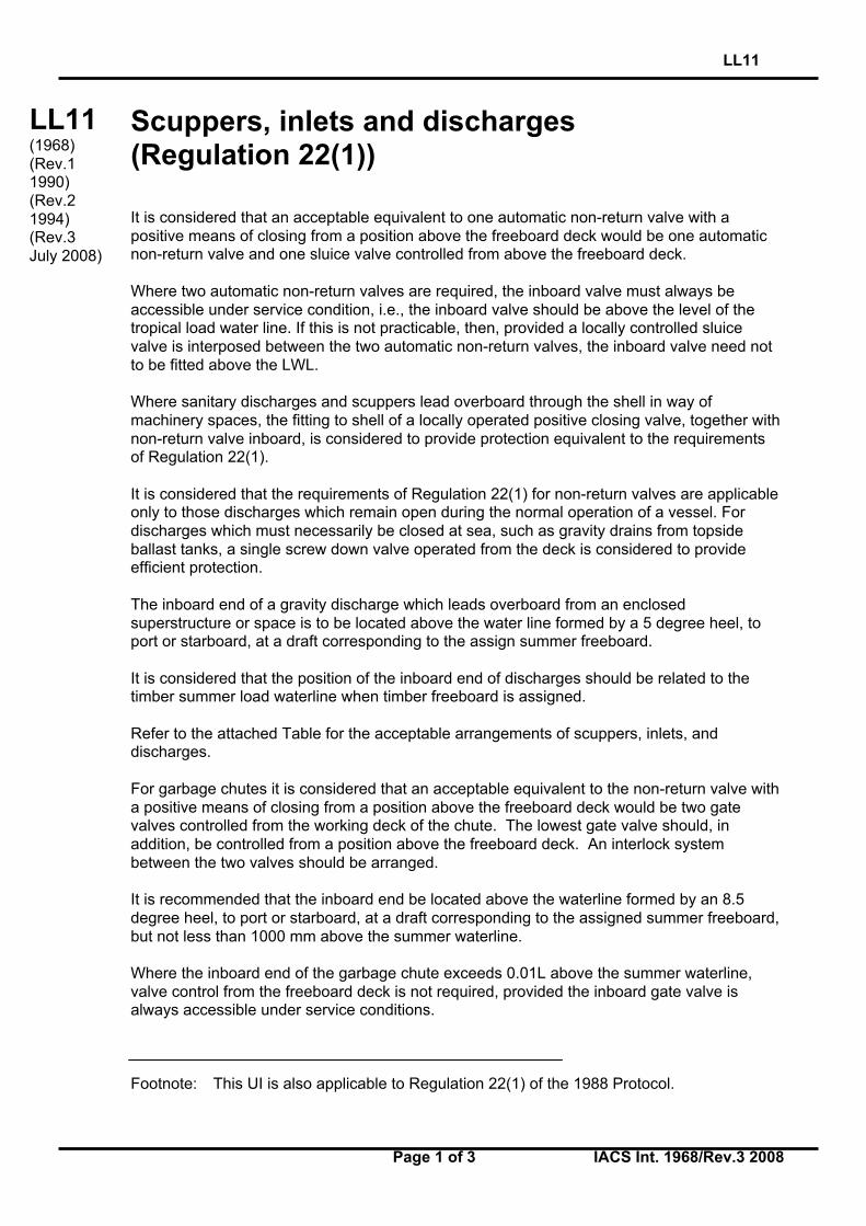
Scuppers, inlets and discharges(Regulation 22(1))
It is considered that an acceptable equivalent to one automatic non-return valve with apositive means of closing from a position above the freeboard deck would be one automaticnon-return valve and one sluice valve controlled from above the freeboard deck.
Where two automatic non-return valves are required, the inboard valve must always beaccessible under service condition, i.e., the inboard valve should be above the level of thetropical load water line. If this is not practicable, then, provided a locally controlled sluicevalve is interposed between the two automatic non-return valves, the inboard valve need notto be fitted above the LWL.
Where sanitary discharges and scuppers lead overboard through the shell in way ofmachinery spaces, the fitting to shell of a locally operated positive closing valve, together withnon-return valve inboard, is considered to provide protection equivalent to the requirementsof Regulation 22(1).
It is considered that the requirements of Regulation 22(1) for non-return valves are applicableonly to those discharges which remain open during the normal operation of a vessel. Fordischarges which must necessarily be closed at sea, such as gravity drains from topsideballast tanks, a single screw down valve operated from the deck is considered to provideefficient protection.
The inboard end of a gravity discharge which leads overboard from an enclosedsuperstructure or space is to be located above the water line formed by a 5 degree heel, toport or starboard, at a draft corresponding to the assign summer freeboard.
It is considered that the position of the inboard end of discharges should be related to thetimber summer load waterline when timber freeboard is assigned.
Refer to the attached Table for the acceptable arrangements of scuppers, inlets, anddischarges.
For garbage chutes it is considered that an acceptable equivalent to the non-return valve witha positive means of closing from a position above the freeboard deck would be two gatevalves controlled from the working deck of the chute. The lowest gate valve should, inaddition, be controlled from a position above the freeboard deck. An interlock systembetween the two valves should be arranged.
It is recommended that the inboard end be located above the waterline formed by an 8.5degree heel, to port or starboard, at a draft corresponding to the assigned summer freeboard,but not less than 1000 mm above the summer waterline.
Where the inboard end of the garbage chute exceeds 0.01L above the summer waterline,valve control from the freeboard deck is not required, provided the inboard gate valve isalways accessible under service conditions.
Footnote: This UI is also applicable to Regulation 22(1) of the 1988 Protocol.
LL11(1968)(Rev.11990)(Rev.21994)(Rev.3July 2008)
LL11
Page 2 of 3 IACS Int. 1968/Rev.3 2008
LL11(cont)
The distance between the two gate valves should be adequate to allow the smooth operationof the interlock system.
Alternatively, the upper gate valve may be replaced by a hinged weathertight cover at theinboard end of the chute together with a discharge flap which replaces the lower gate valve.
The cover and flap are to be arranged with an interlock so that the discharge flap cannot beoperated until the hopper cover is closed.
The chute is to be constructed of material of substantial thickness up to, and including, thecover.
The gate valve(s) controls and/or hinged cover are to be clearly marked: “Keep closed whennot in use”.
Where the inboard end of a garbage chute is below the margin line in a passenger ship, orthe critical (crucial) waterline of a cargo ship of more than 100 m in length then:
(i) the inboard end hinged cover/valve is to be watertight.
(ii) the valve is to be a screw-down non-return valve fitted in an easily accessible positionabove the deepest subdivision load line.
(iii) the screw-down non-return valve is to be controlled from a position above the bulkheaddeck and provided with open/shut indicators. The valve control is to be clearly marked:“Keep closed when not in use”.
Where plastic pipes are used for sanity discharges and scuppers, they are also subject to therequirements of the Table, and the valve at the shell is to be operated from outside the spacein which the valve is located.
Where such plastic pipes are located below the summer waterline (timber summer loadwaterline), the valve is to be operated from a position above the freeboard deck.
The portion of discharge line from the shell to the first valve as well as shell fittings and valvesshall be of steel, bronze or other approved ductile material.
The approval of plastic piping in any location will be subject to the consideration of strengthand fire hazards involved with special reference to penetrations through bulkheads, decks orother significant compartment boundaries.
Attention must also be paid to valid fire technical regulations.
LL11
Page 3 of 3 IACS Int. 1968/Rev.3 2008
LL11(cont)
End ofDocument
LL12
Page 1 of 1 IACS Int. 1968
LL
(cont)
Side scutters (Regulation 23)
Deleted (July 2008)
LL12(1968)
End ofDocument
LL13
Page 1 of 1 IACS Int. 1968/Rev.1 2008
LL
(cont)
Freeing ports (Regulation 24(1) and 24(5))
Regulation 24(1):
On a flush deck ship with a substantial deckhouse amidships it is considered that thedeckhouse provides sufficient break to form two wells and that each could be given therequired freeing port area based upon the length of the 'well'. It would not then be allowed tobase the area upon 0.7L.
In defining a substantial deckhouse it is suggested that the breadth of the deckhouse shouldbe at least 80% of the beam of the vessel, and that the passageways along the side of theship should not exceed 1.5 m (4.9 ft) in width.
Where a screen bulkhead is fitted completely across the vessel, at the forward end of amidship deck house, this would effectively divide the exposed deck into wells and nolimitation on the breadth of the deckhouse is considered necessary in this case.
It is considered that wells on raised quarterdecks should be treated as previously, i.e. asbeing on freeboard decks.
Regulation 24(5):
With zero or little sheer on the exposed freeboard deck or an exposed superstructure deck itis considered that the freeing port area should be spread along the length of the well.
Footnote: This UI is also applicable to Regulation 24(1) and 24(5) of the 1988 Protocol.
LL13(1968)(Rev.1July 2008)
End ofDocument
LL14
Page 1 of 1 IACS Int. 1968/Rev.1 2008/Corr.1 2015
LL (cont)
Protection of the crew (Regulation 25(2)) Regulation 25(2) (2) Efficient guard rails or bulwarks shall be fitted to all exposed parts of the freeboard and superstructure decks. The height of the bulwarks or guard rails shall be at least 1 metre (39 ½ inches) from the deck, provided that where this height would interfere with the normal operation of the ship, a lesser height may be approved if the Administration is satisfied that adequate protection is provided. Interpretation A guard rail should also be required for first tier deckhouses and for superstructures' ends. Footnote: This UI is also applicable to Regulation 25(2) of the 1988 Protocol.
LL14 (1968) (Rev.1 July 2008) (Corr.1 Oct 2015)
End of Document
LL15
Page 1 of 1 IACS Int. 1968/Rev.3 2008
LL
(cont)
Length of superstructure(Regulation 34(1) and 34(2))
Regulation 34(1):
Where a superstructure bulkhead is recessed, the effective length of the superstructure shallbe reduced by an amount equivalent in area to the area of the recess related to the breadthof the ship at the mid-length of the recess.
Where the recess is unsymmetrical about the centre line, the largest portion of the recessshall be considered as applying to both sides of the ship.
It is considered that such a recess need not be decked over.
Where a cargo hatchway, complying with the requirements of regulation 16 and having acoaming height that extends above the level of the superstructure deck, is fitted in the recessand covering the whole area of the recess, the hatchway may be taken into account asforming a part of the superstructure, and the effective length of the superstructure need notbe reduced by the amount equivalent in area to the area of the recess.
The hatchway coaming height shall be in accordance with Regulation 16(1), measured fromthe superstructure deck level.
Regulation 34(2):
Where there is an extension to a superstructure, which extension has a breadth on each sideof the centre line at least 30% of the breadth of the ship, the effective length of thesuperstructure may be increased by considering an equivalent superstructure bulkhead in theform of a parabola. This parabola should extend from the extension at the centre line andpass through the junction of the actual superstructure bulkhead with the sides of theextension and extend to the sides of the ship. This parabola should be completely containedwithin the boundary of the superstructure and its extensions.
If the superstructure is set-in from the side, up to the limit allowed under Regulation 3(10), theequivalent bulkhead should be calculated on the basis of the actual breadth of thesuperstructure (not the breadth of the ship).
Note: Changes introduced in Rev.2 (July 2003) are to be uniformly implemented by IACSMembers and Associates from 1 January 2004.
Footnotes:
1. This UI is also applicable to Regulation 34(1) and 34(2) of the 1988 Protocol.
2 Changes introduced in Rev.2 (July 2003) are also applicable to Regulation 34(1) of therevised 1988 Protocol.
LL15(1968)(Rev.11993)(Rev.2July 2003)(Rev.3July 2008)
End ofDocument
LL16
Page 1 of 1 IACS Int. 1968/Rev.1 2008
LL
(cont)
Sheer (Regulation 38)
Where the height of a superstructure is less than standard, paragraph 12 may be appliedexcept that the superstructure deck shall not be less than the minimum height of thesuperstructure above the virtual shear curve at any point.
For this purpose y shall be taken as the difference between the actual and minimum height ofthe superstructure at the end of sheer.
Footnote: This UI is also applicable to Regulation 38 of the 1988 Protocol.
LL16(1968)(Rev.1July 2008)
End ofDocument
LL17(cont)
LL17
Page 1 of 4 IACS Int. 1968/Rev.1 2008
Minimum bow height (Regulation 39(1) and39(2))When a ship built on or after 21 July 1968 is arranged to suit exceptional operationalrequirements such that the forecastle and/or sheer forward do not meet the provisions ofparagraphs (1) and (2) of Regulation 39 of the 1966 ICLL, the increase of calculated summerfreeboard may, with the concurrence of the Administration, be determined in the followingways.
Nomenclature
∆E0 ≥ 0 Bow height penalty
Smin = Hmin - fbds
HminMinimum bow height calculated according to paragraph (1) ofthis Regulation
fbds Summer freeboard
d ≤ 0.15L Extent of sheer (measured from FP)
lF ≤ 0.07L Mean covered length of forecastle
h Height of forecastle measured at FP from zero sheer line
SFP Actual sheer measured at FP
SBHD Actual sheer in way of forecastle bulkhead
2
min1 15.015.0
−=
LlL
SS F Theoretical sheer in way of forecastle bulkheadcorresponding to Smin
2
2 15.015.0
−=
LlL
hS F Theoretical sheer in way of forecastle bulkheadcorresponding to h
Note: This UI may also be applied to Regulation 39(1) and 39(2) of the 1988 Protocol andthe revised 1988 Protocol upon the special consideration by the Administration.
LL17(1968)(Corr.1996)(Corr.1June2006)(Corr.2Oct 2007)(Rev.1July 2008)
LL17(cont)
LL17
Page 2 of 4 IACS Int. 1968/Rev.1 2008
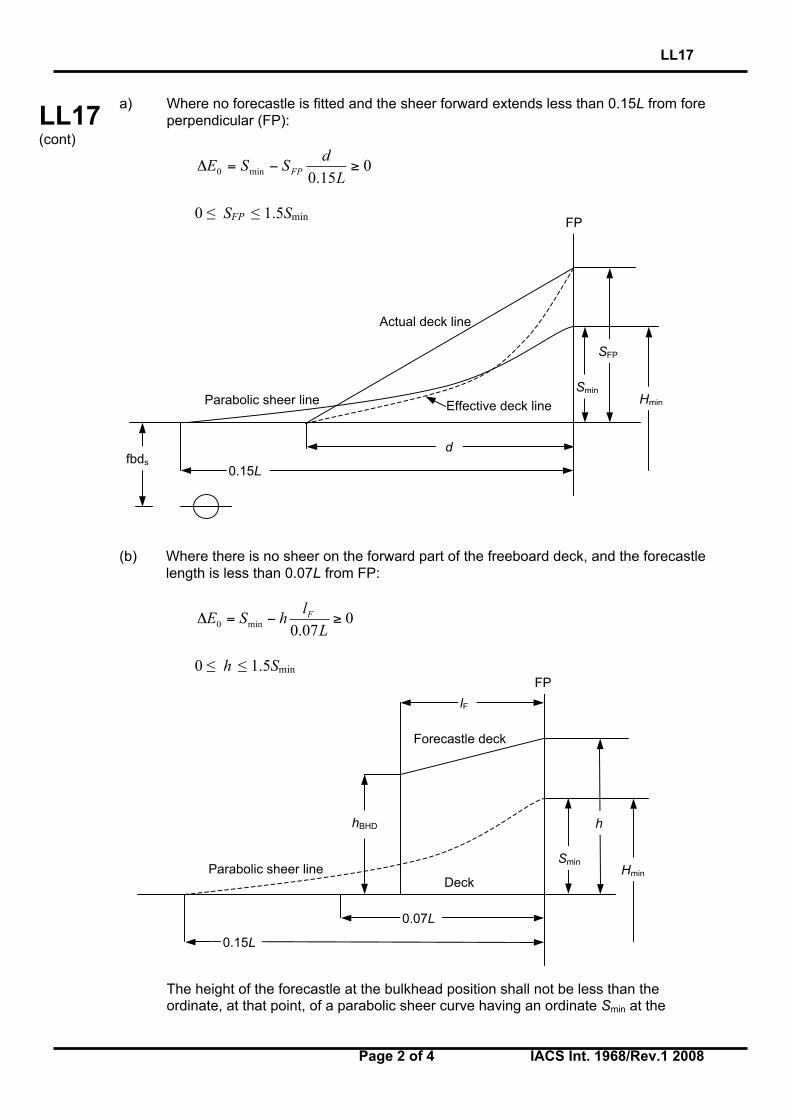
a) Where no forecastle is fitted and the sheer forward extends less than 0.15L from foreperpendicular (FP):
015.0min0 ≥−=ΔL
dSSE FP
0 ≤ SFP ≤ 1.5Smin
(b) Where there is no sheer on the forward part of the freeboard deck, and the forecastlelength is less than 0.07L from FP:
007.0min0 ≥−=ΔL
lhSE F
0 ≤ h ≤ 1.5Smin
The height of the forecastle at the bulkhead position shall not be less than theordinate, at that point, of a parabolic sheer curve having an ordinate Smin at the
Parabolic sheer line
Forecastle deck
lF
hBHD
SminHmin
h
0.15L
0.07L
Deck
FP
Actual deck line
Parabolic sheer line Effective deck line
fbds0.15L
SminHmin
SFP
d
FP
LL17(cont)
LL17
Page 3 of 4 IACS Int. 1968/Rev.1 2008
forward perpendicular and extending aft for a distance of 0.15L from the forwardperpendicular.
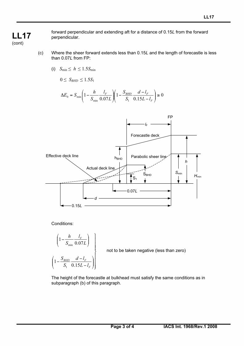
(c) Where the sheer forward extends less than 0.15L and the length of forecastle is lessthan 0.07L from FP:
(i) Smin ≤ h ≤ 1.5Smin
0 ≤ SBHD ≤ 1.5S1
015.0
107.0
11min
min0 ≥
−−
−
−=Δ
F
FBHDF
lLld
SS
Ll
Sh
SE
Conditions:
−−
−
−
F
FBHD
F
lLld
SS
Ll
Sh
15.01
07.01
1
min
not to be taken negative (less than zero)
The height of the forecastle at bulkhead must satisfy the same conditions as insubparagraph (b) of this paragraph.
Actual deck line
Forecastle deck
lF
hBHD
0.07L
SminHmin
h
FP
0.15L
Parabolic sheer line
S1
Effective deck line
SBHD
d
LL17(cont)
LL17
Page 4 of 4 IACS Int. 1968/Rev.1 2008
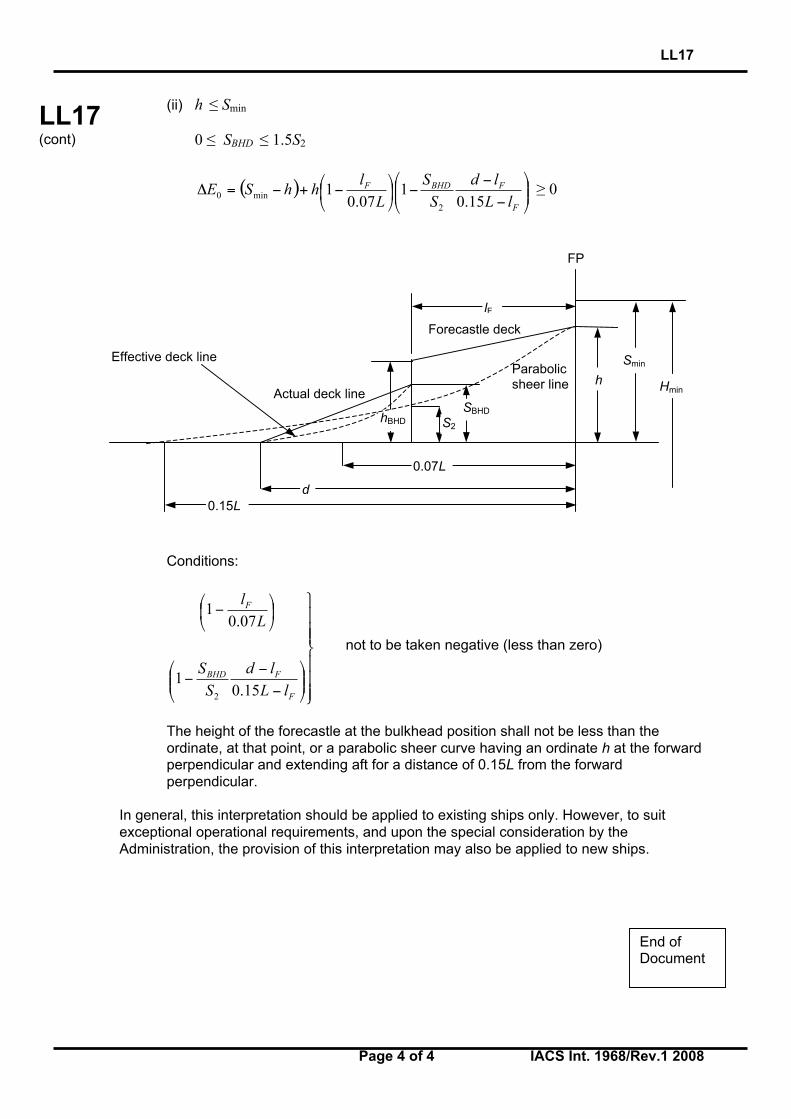
(ii) h ≤ Smin
0 ≤ SBHD ≤ 1.5S2
( )
−−
−
−+−=ΔF
FBHDF
lLld
SS
Ll
hhSE15.0
107.0
12
min0 ≥ 0
Conditions:
−−
−
−
F
FBHD
F
lLld
SS
Ll
15.01
07.01
2
not to be taken negative (less than zero)
The height of the forecastle at the bulkhead position shall not be less than theordinate, at that point, or a parabolic sheer curve having an ordinate h at the forwardperpendicular and extending aft for a distance of 0.15L from the forwardperpendicular.
In general, this interpretation should be applied to existing ships only. However, to suitexceptional operational requirements, and upon the special consideration by theAdministration, the provision of this interpretation may also be applied to new ships.
End ofDocument
Parabolicsheer line
S2
Actual deck line
FP
0.15L
SBHD
d
0.07L
Forecastle deck
lF
Effective deck line
h Hmin
Smin
hBHD
LL18
Page 1 of 1 IACS Int. 1968/Rev.1 2008
LL
(cont)
Freeboard tables (Regulation 28)
(a) Type A ships
(i) Freeboards for Type A ships with lengths between 365 m and 400 m shall be determinedby the following formula:
f = 221 + 16,10L - 0,02L2
where f is the freeboard in mmL is the length as defined in Regulation 3(1).
(ii) Freeboards for Type A ships with lengths of 400 m and above shall be the constantvalue, 3460 mm.
(b) Type B ships
(i) Freeboards for Type B ships with lengths between 365 m and 400 m shall be determinedby the following formula:
f = - 587 + 23L - 0,0188L2
where f is the freeboard in mmL is the length as defined in Regulation 3(1).
(ii) Freeboards for Type B ships with lengths of 400 m and above shall be the constantvalue, 5605 mm.
Footnote: This UI is also applicable to Regulation 28 of the 1988 Protocol and the revised1988 Protocol.
LL18(1968)(Rev.1July 2008)
End ofDocument
LL19
Page 1 of 1 IACS Int. 1972/Rev.1 2008
LL
(cont)
Form of certificates (Article 18)
It is recommended that the model form of certificates given in Annex III of the Load LineConvention should be strictly adhered to and any deviations from this pattern should beavoided.
Footnote: This UI is also applicable to Article 18 of the 1988 Protocol and the revised 1988Protocol.
LL19(1972)(Rev.1July 2008)
End ofDocument
LL20
Page 1 of 1 IACS Int. 1972/Rev.1 2008
LL
(cont)
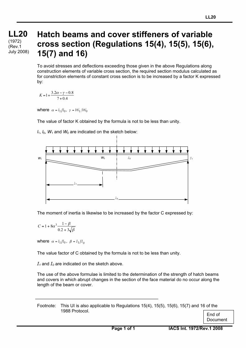
Hatch beams and cover stiffeners of variablecross section (Regulations 15(4), 15(5), 15(6),15(7) and 16)To avoid stresses and deflections exceeding those given in the above Regulations alongconstruction elements of variable cross section, the required section modulus calculated asfor constriction elements of constant cross section is to be increased by a factor K expressedby:
4.07
8.02.31
+
−−+=
γαK
where 0101 , WWll == γα
The value of factor K obtained by the formula is not to be less than unity.
l1, l0, W1 and W0 are indicated on the sketch below:
The moment of inertia is likewise to be increased by the factor C expressed by:
β
βα
32.0
181 3
+
−+=C
where 0101 , IIll == βα
The value factor of C obtained by the formula is not to be less than unity.
I1 and I0 are indicated on the sketch above.
The use of the above formulae is limited to the determination of the strength of hatch beamsand covers in which abrupt changes in the section of the face material do no occur along thelength of the beam or cover.
Footnote: This UI is also applicable to Regulations 15(4), 15(5), 15(6), 15(7) and 16 of the1988 Protocol.
l1
W0 I0
l0
I1W1
LL20(1972)(Rev.1July 2008)
End ofDocument
LL21
Page 1 of 1 IACS Int. 1972/Rev.1 2008
LL
(cont)
Cargo ports or similar openings below theuppermost load line (Regulation 21(2))
It is recommended that cargo ports or similar openings may be accepted submerged providedthe safety of the ship is in no way impaired. It is considered that the fitting of a second door ofequivalent strength and watertightness is one acceptable arrangement. In that case leakagedetection device should be provided in the compartment between the two doors. Further,drainage of this compartment to the bilges controlled by an easily accessible screw downvalve, should be arranged. The outer door should preferably open outwards.
Footnote: This UI is also applicable to Regulation 21(2) of the 1988 Protocol.
LL21(1972)(Rev.1July 2008)
End ofDocument
LL22
Page 1 of 1 IACS Int. 1972/Rev.1 2008
LL
(cont)
Position of the inboard end of discharges whentimber freeboard is assigned (Regulation 22(1))
It is considered that the position of the inboard end of discharges should be related to thetimber summer load waterline when timber freeboard is assigned.
Footnotes:
1. This UI is also applicable to Regulation 22(1) of the 1988 Protocol.
2. This UI is also applicable to Regulation 22-1 of the revised 1988 Protocol.
LL22(1972)(Rev.1July 2008)
End ofDocument
LL23
Page 1 of 1 IACS Int. 1972/Rev.1 2008
LL
(cont)
Freeing arrangement(Regulations 26(5), 27(7) and 36(1)(e))
1. Regulation 27(7): Freeing arrangements on ships having reduced B freeboardassigned and fitted with bulwarks on the freeboard deck
For Type B ships with freeboards reduced by not more than 60% of the difference between Band A tables there shall be freeing port area in the lower part of the bulwarks equal to at least25% of the total area of the bulkwarks. The upper edge of the sheer strake shall be kept aslow as possible.
2. Regulations 26(5) and 36(1)(e): Freeing arrangements for Type A ships and Type Bships with trunks
It is considered that a freeing port area, in the lower part of the bulwarks, of 33% of the totalarea of the bulwarks provides the 'other effective freeing arrangements' mentioned inRegulation 26(5), and may be considered equivalent to the 50% open rails in way of trunksrequired by Regulation 36(1)(e).
Footnotes:
1. This UI is also applicable to Regulations 26(5), 27(8) and 36(1)(e) of the 1988 Protocol.
2. Paragraph 1 of this UI is also applicable to Regulation 27(8) of the revised 1988 Protocol.
LL23(1972)(Rev.1July 2008)
End ofDocument

LL24
Page 1 of 1 IACS Int. 1972/Rev.1 2008
LL
(cont)
Negative depth correction (Regulation 31(3))
When the height of a superstructure, raised quarterdeck or trunk is less than thecorresponding standard height, it is recommended that the calculated reduction be correctedin the ratio of the height of the actual superstructure, raised quarterdeck or trunk to theapplicable standard height as defined in Regulation 33.
Footnote: This UI is also applicable to Regulation 31(3) of the 1988 Protocol and the revised1988 Protocol.
LL24(1972)(Rev.1July 2008)
End ofDocument
LL25
Page 1 of 1 IACS Int. 1972/Rev.1 2008
LL
(cont)
Effective length of raised quarterdeck(Regulation 35(4))
It is recommended that the maximum effective length of 0.6L of a raised quarterdeck which isstipulated by Regulation 35(4), is to be measured from the after perpendicular even where apoop is fitted in conjunction with the raised quarterdeck.
Footnote: This UI is also applicable to Regulation 35(4) of the 1988 Protocol.
LL25(1972)(Rev.1July 2008)
End ofDocument

LL26
Page 1 of 1 IACS Int. 1972/Rev.2 2008
LL
(cont)
Continuous hatchways as trunk (Regulation 36)
It is recommended that continuous hatchways may be treated as a trunk in the freeboardcomputation provided Regulation 36 is complied with in all respects.
The trunk deck stringer referred to in Regulation 36(1)(b) may be fitted outboard of the trunkside bulkhead in association with the following:
(i) The stringer so formed is to provide a clear walkway of at least 450 mm in width on eachside of the ship.
(ii) The stringer is to be of solid plate efficiently supported and stiffened.(iii) The stringer is to be as high above the freeboard deck as practicable. In the freeboard
calculation, the trunk height is to be reduced by at least 600 mm or by the actualdifference between the top of the trunk and the stinger, whichever is greater.
(iv) Hatch cover securing appliances are to be accessible from the stringer or walkway.(v) The breadth of the trunk is to be measured between the trunk side bulkheads.(vi) Regulation 36 is to be complied with in all other respects.
Footnote: This UI is also applicable to Regulation 36 of the 1988 Protocol.
LL26(1972)Rev.11983)(Rev.2July 2008)
End ofDocument
LL27
Page 1 of 1 IACS Int. 1972/Rev.1 2008
LL
(cont)
Less than standard hatch coamings on trunksof less than standard height (Regulation 36(4))
In the case where the trunk height is less than standard and the trunk hatch coamings arealso of less than standard height, or omitted entirely, doubt may arise whether the trunkhatchways are located in position 1 or position 2 and, consequently, about the reduction to bemade in the actual trunk height. It is considered that in these cases the reduction from theactual height of trunk on account of insufficient hatch coaming height shall be taken as thedifference between 600 mm and the actual height of coaming, or 600 mm if no hatchcoamings are fitted. Reduction in the actual height of trunk shall not be required in caseswhere only small hatches with less than standard height coamings are fitted in the trunk deckfor which dispensation from the requirement of standard coaming height may be given.
Footnote: This UI is applicable to Regulation 36(4) of the 1988 Protocol.
LL27(1972)(Rev.1July 2008)
End ofDocument
LL28
Page 1 of 1 IACS Int. 1972/Rev.1 2008
LL
(cont)
Deduction for superstructures and trunks(Regulations 37 and 38(12))
For the purpose of applying the table ‘Percentage of Deduction for Type B ships’ inRegulation 37(2) it is considered that any detached superstructure abaft midship whose afterbulkhead is located 0.05L or more forward of the after perpendicular may be treated as adetached bridge.
A superstructure whose after bulkhead is located within 0.05L from the after perpendicularshall not qualify as a detached bridge.
Any excess in the height of such a superstructure, which does not extend to the afterperpendicular, cannot be regarded as contributing to the sheer allowance contemplated inRegulation 38(12).
Footnote: This UI is applicable to Regulations 37 and 38(12) of the 1988 Protocol.
LL28(1972)(Rev.1July 2008)
End ofDocument

LL29
Page 1 of 2 IACS Req. 1972/Rev.2 2008
LL29(cont)
Sheer Credit for Superimposed Superstructures(Regulation 38(5), 38(7) and 38(12))
(a) Regulation 38(5): Superstructures superimposed on a complete superstructure.
In applying Regulation 38(5) (sheer on a complete superstructure ship) where there is anenclosed poop or forecastle superimposed on a complete superstructure, sheer credit shallbe allowed for such a poop or forecastle, according to the method of Regulation 38(12) asshown in Fig 1.
Fig. 1
(b) Regulation 38(7): Superstructures superimposed on a forecastle or poop (i.e. astepped forecastle or poop).
In applying Regulation 38(7) and 38(12) where a poop or forecastle consists of two layers,the method shown in Fig 2 shall be used:
Fig. 2
Footnote: This UI is applicable to Regulations 38(5), 38(7) and 38(12) of the 1988 Protocol.
LL29(1972)(Rev.11983)(Rev.2July 2008)

LL29
Page 2 of 2 IACS Req. 1972/Rev.2 2008
LL29(cont)
In the above the following definitions apply:
Z is as per Regulation 38(5).
Zv is the end ordinate of a virtual standard parabolic curve taken through the point "X". If Zv isgreater than (Z+h), the end ordinate shall be (Z+h), in which case point "X" shall bedisregarded and curve (2) not taken into account.
When the length of the first tier superstructure is greater than 0.5L, the virtual standardparabolic curve shall commence at amidships as indicated in Fig 1.
End ofDocument
LL30
Page 1 of 1 IACS Req. 1972/Rev.1 2008
A2(cont)
Sheer allowance for excess height ofsuperstructure (Regulations 38(7) and 38(12))
As Regulation 38(7) and (12) does not refer to a raised quarter deck it is recommended thatcredit under this paragraph be given for this type of superstructure only when the height ofthe raised quarterdeck is greater than the standard height of 'other superstructures' asdefined in Regulation 33, and only for the amount by which the actual height of the raisedquarterdeck exceeds that standard height.
Footnote: This UI is applicable to Regulations 38(7) and 38(12) of the 1988 Protocol.
LL30(1972)(Rev.1July 2008)
End ofDocument
LL31
Page 1 of 1 IACS Req. 1972/Rev.1 2008
A2(cont)
Deduction for excess sheer(Regulation 38(15))
Since no stipulation is made as to the height of the superstructure referred to in Regulation38(15), it is recommended that the height of this superstructure shall be related to itsstandard height. When the height of the superstructure or raised quarterdeck is less thanstandard, the reduction shall be in the ratio of the actual to the standard height thereof.
Footnote: This UI is applicable to Regulation 38(15) of the 1988 Protocol.
LL31(1972)(Rev.1July 2008)
End ofDocument
LL32
Page 1 of 1 IACS Req. 1972
A2(cont)
Special requirements for vehicle ferries,ro-ro ships and other ships of similar typeWithdrawn Oct 2007, re-categorised as UI SC220 (NEW Oct 2007)
LL32(1972)
End ofDocument
LL33
Page 1 of 1 IACS Int. 1972/Rev.1 2008
LL
(cont)
Timber freeboards for ships having reducedType B freeboards assigned (Regulations 45(2)and 45(3))
It is understood that some Administrations accept that timber freeboards may be assigned toships with reduced Type B freeboards, provided the timber freeboards are calculated on thebasis of the ordinary Type B freeboard.
It is recommended that Regulation 45(2) and (3) is interpreted or, if necessary, amendedsuch that the Timber Winter mark and/or the Timber Winter North Atlantic mark are placed atthe same level as the reduced Type B Winter mark when the computed Timber Winter markand/or the computed Timber Winter North Atlantic mark fall below the reduced Type B Wintermark.
Footnote: This UI is applicable to Regulations 45(2) and 45(3) of the 1988 Protocol.
LL33(1972)(Rev.1July 2008)
End ofDocument
LL34
Page 1 of 1 IACS Int. 1972 / Corr.1 2008
LL
(cont)
Freeboard for lighters and barges (Regulation27(11) of 1966 ILLC)
In applying Regulation 27(11) to deck cargo barges it is recommended that only Type Bfreeboard can be assigned, even if the barges possess the same integrity of exposed decksand equivalent safety against flooding as normal tank barges.
This view is taken as a result of the consideration that Type A freeboard can only be assignedto liquid cargo barges.
It is further concluded that deck cargo can only be carried on barges to which Type Bfreeboard is assigned.
LL34(1972)(Corr.1July 2008)
End ofDocument
LL35
Page 1 of 1 IACS Int. 1972/Corr.1 2008
LL
(cont)
Stowage of timber deck cargo on ships havingtimber freeboards assigned (Regulations 44and 45)
It is recommended that for the purpose of applying Regulation 45 the timber deck cargo shallextend as far outboard as possible due allowance being given for obstructions such as guardrails, stanchions, uprights, etc.
LL35(1972)(Corr.1July 2008)
End ofDocument
LL36
Page 1 of 1 IACS Int. 1975/Rev.2 2008
LL
(cont)
Minimum wall thickness of pipes (Regulations19, 20 and 22)
For pipes covered by the above Regulations the following minimum wall thicknesses arerecommended:
(a) (i) For scupper and discharge pipes, where substantial thickness is not required;and(ii) For venting pipes other than specified under (c):
- external diameter of pipes equal to or less than 155 mm: thickness not lessthan 4,5 mm
- external diameter of pipes equal to or more than 230 mm: thickness not lessthan 6,0 mm
intermediate sizes are to be determined by linear interpolation.
(b) For scupper and discharge pipes where substantial thickness is required:- external diameter of pipes equal to or less than 80 mm: thickness not less than 7,0
mm- external diameter of pipes 180 mm: thickness not less than 10,0 mm- external diameter of pipes equal to or more than 220 mm: thickness not less than
12,5 mmintermediate sizes are to be determined by linear interpolation.
(c) For venting pipes in position 1 and 2 leading to spaces below the freeboard deck or tospaces within enclosed superstructures:
- external diameter of pipes equal to or less than 80 mm: thickness not less than 6,0mm
- external diameter of pipes equal to or more than 165 mm: thickness not less than8,5 mm
intermediate sizes are to be determined by linear interpolation.
Footnotes:
1. This UI is also applicable to Regulations 19, 20 and 22 of the 1988 Protocol.
2. Paragraphs (a)(ii) and (c) are also applicable to Regulations 19 and 20 of the revised1988 Protocol.
LL36(1975)(Rev.11978)(Rev.2July 2008)
End ofDocument
LL37
Page 1 of 2 IACS Int. 1975/Rev.2 2008
LL37(cont)
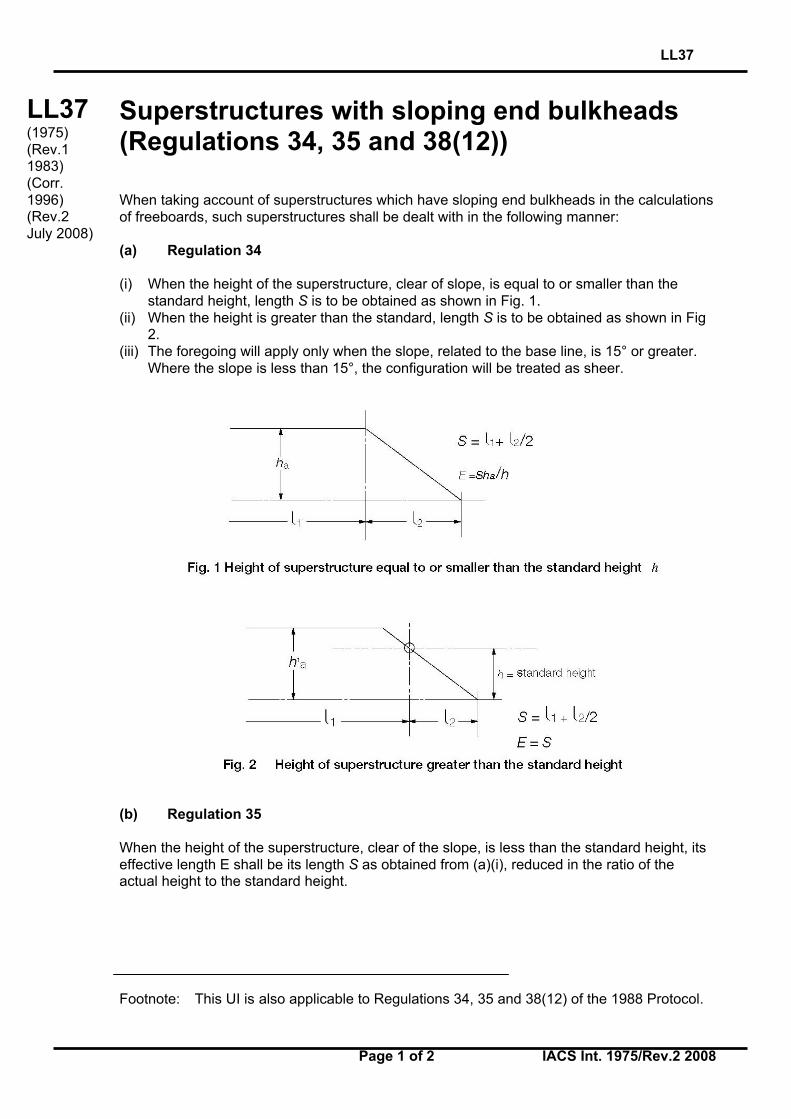
Superstructures with sloping end bulkheads(Regulations 34, 35 and 38(12))
When taking account of superstructures which have sloping end bulkheads in the calculationsof freeboards, such superstructures shall be dealt with in the following manner:
(a) Regulation 34
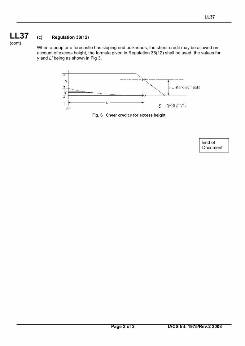
(i) When the height of the superstructure, clear of slope, is equal to or smaller than thestandard height, length S is to be obtained as shown in Fig. 1.
(ii) When the height is greater than the standard, length S is to be obtained as shown in Fig2.
(iii) The foregoing will apply only when the slope, related to the base line, is 15° or greater.Where the slope is less than 15°, the configuration will be treated as sheer.
(b) Regulation 35
When the height of the superstructure, clear of the slope, is less than the standard height, itseffective length E shall be its length S as obtained from (a)(i), reduced in the ratio of theactual height to the standard height.
Footnote: This UI is also applicable to Regulations 34, 35 and 38(12) of the 1988 Protocol.
LL37(1975)(Rev.11983)(Corr.1996)(Rev.2July 2008)
LL37
Page 2 of 2 IACS Int. 1975/Rev.2 2008
LL37(cont)
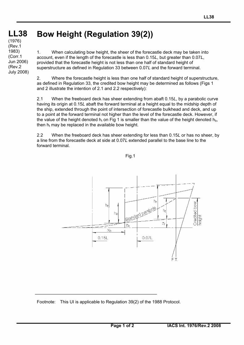
(c) Regulation 38(12)
When a poop or a forecastle has sloping end bulkheads, the sheer credit may be allowed onaccount of excess height, the formula given in Regulation 38(12) shall be used, the values fory and L’ being as shown in Fig 3.
End ofDocument
LL38
Page 1 of 2 IACS Int. 1976/Rev.2 2008
LL38(cont)
Bow Height (Regulation 39(2))
1. When calculating bow height, the sheer of the forecastle deck may be taken intoaccount, even if the length of the forecastle is less than 0.15L, but greater than 0.07L,provided that the forecastle height is not less than one half of standard height ofsuperstructure as defined in Regulation 33 between 0.07L and the forward terminal.
2. Where the forecastle height is less than one half of standard height of superstructure,as defined in Regulation 33, the credited bow height may be determined as follows (Figs 1and 2 illustrate the intention of 2.1 and 2.2 respectively):
2.1 When the freeboard deck has sheer extending from abaft 0.15L, by a parabolic curvehaving its origin at 0.15L abaft the forward terminal at a height equal to the midship depth ofthe ship, extended through the point of intersection of forecastle bulkhead and deck, and upto a point at the forward terminal not higher than the level of the forecastle deck. However, ifthe value of the height denoted ht on Fig 1 is smaller than the value of the height denoted hb,then ht may be replaced in the available bow height.
2.2 When the freeboard deck has sheer extending for less than 0.15L or has no sheer, bya line from the forecastle deck at side at 0.07L extended parallel to the base line to theforward terminal.
Fig.1
Footnote: This UI is applicable to Regulation 39(2) of the 1988 Protocol.
LL38(1976)(Rev.11983)(Corr.1Jun 2006)(Rev.2July 2008)
LL38
Page 2 of 2 IACS Int. 1976/Rev.2 2008
LL38(cont)
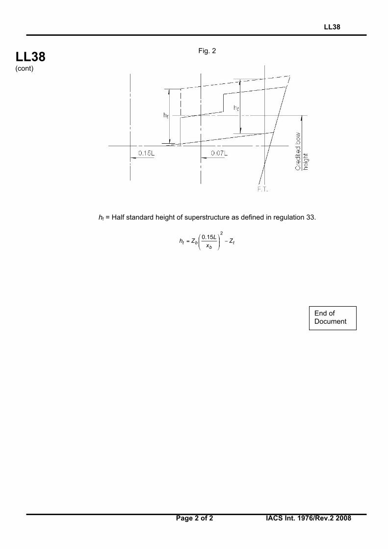
Fig. 2
hf = Half standard height of superstructure as defined in regulation 33.
tb
bt ZxL
Zh −
=
215.0
End ofDocument
LL39
Page 1 of 1 IACS Int. 1977/Rev.1 2008
LL
(cont)
Structure of a lower freeboard deck (Regulation3(9))
When a lower deck is designated as the freeboard deck, it shall be continuous in fore and aftdirection as well as athwartships. Such a freeboard deck as a minimum shall consist ofsuitable framed stringers at the ship sides and transversely at each watertight bulkhead whichextends to the upper deck, within cargo spaces. The width of these stringers shall not be lessthan can be conveniently fitted having regard to the structure and the operation of the ship.Any arrangement of stringers shall be such that structural requirements can also be met.
NOTE
Member Societies formulated this Interpretation in order to have a guide when judging whether astructure below the uppermost complete deck can be designated as a freeboard deck in terms ofRegulation 3(9) for the application of tonnage regulations. This was done, although it is obvious thatsuch a structure has no significance with regard to the philosophy of the Load Line Convention.
Nevertheless it is felt that it would be preferable if tonnage and load line matters could be clearlyseparated by deleting from the Load Line Convention the reference to a lower deck being designatedas the freeboard deck.
Footnote: This UI is also applicable to to Regulation 3(9) of the 1988 Protocol.
LL39(1977)(Rev.1July 2008)
End ofDocument
LL40
Page 1 of 1 IACS Int. 1977/Rev.2 2008
LL
(cont)
Security of hatch covers (Regulation 15(13))
Acceptable equivalent means to steel bars shall consist of devices and materials which willprovide strength equivalent to, and elasticity not greater than that of, steel.
Steel wire ropes cannot be regarded as satisfactory equivalent means.
Care is to be taken that tarpaulins are adequately protected from the possibility of damagearising from the use of securing devices which do not provide a flat bearing surface.
Footnotes:
1. This UI is also applicable to Regulation 15(13) of the 1988 Protocol.
2. This UI is also applicable to Regulation 15(12) of the revised 1988 Protocol.
LL40(1977)(Rev.11980)(Rev.2July 2008)
End ofDocument
LL41
Page 1 of 1 IACS Int. 1978/Rev.1 2008
LL
(cont)
Trunks (Regulations 29, 36 and 38)
(a) Where the length of a trunk, corrected for breadth and height as may be appropriate,can be included in the effective length used for calculating the correction for superstructuresin accordance with Regulation 37, it shall not be taken into account for calculating the totallength S for the purpose of sheer correction according to Regulation 38(13).
(b) The effective length of superstructures E which is used for calculating the freeboardcorrection according to Regulation 29 shall be determined excluding the length of trunks.
(c) The inclusion of a trunk in the calculation of freeboard need not prohibit the fitting ofopenings in the bulkheads of adjacent superstructures such as poops, bridges or forecastlesprovided there is no direct communication between the superstructure and the trunk.
(d) The sides of a trunk included in the calculations of freeboard shall be intact. Sidescuttles of the non-opening type and bolted manhole covers may be allowed.
Footnote: This UI is also applicable to Regulations 29, 36 and 38 of the 1988 Protocol.
LL41(1978)(Rev.1July 2008)
End ofDocument
LL42
Page 1 of 1 IACS Int. 1978/Rev.1 2008
LL
(cont)
Access openings on barges (Regulation 27(11))
(a) Since Regulation 27(11) does not contain any indication as to what size the term‘small access openings’ refers it is recommended that such openings should not be greaterthan 1,5 m2 where a freeboard reduction of 25% is granted.
(b) Access plates are considered as being equivalent to an intact deck for unmannedbarges, thereby allowing for a 25% reduction in freeboard, provided they are secured byclosely spaced bolts, their joining parts are properly gasketed and their arrangements, for allpractical purposes, have equivalent structural integrity and tightness as an intact deck.
Footnote: This UI is also applicable to Regulation 27(14)(c) of the 1988 Protocol and therevised 1988 Protocol.
LL42(1978)(Rev.1July 2008)
End ofDocument

LL43
Page 1 of 1 IACS Int. 1978/Rev.1 2008
LL
(cont)
Minimum bow height (Regulation 39)
On ships to which timber freeboards are assigned Regulation 39 should relate to the summerload waterline and not to the timber summer load waterline.
Footnote: This UI is also applicable to Regulation 39 of the 1988 Protocol.
LL43(1978)(Rev.1July 2008)
End ofDocument
LL44
Page 1 of 1 IACS Int. 1978/Rev.1 2008
LL
(cont)
Freeing ports (Regulation 24(3))
The effectiveness of the freeing area in bulwarks required by Regulation 24(1) and (2)depends on free flow across the deck of a ship. Where there is no free flow due to thepresence of a continuous trunk or hatchway coaming, the freeing area in bulwarks iscalculated in accordance with Regulation 24(3).
The free flow area on deck is the net area of gaps between hatchways, and betweenhatchways and superstructures and deck houses up to the actual height of the bulwark.
The freeing port area in bulwarks should be assessed in relation to the net flow area asfollows:
i. If the free flow area is not less that the freeing area calculated from Regulation 24(3) as ifthe hatchway coamings were continuous, then the minimum freeing port area calculatedfrom Regulation 24(1) and (2) should be deemed sufficient.
ii. If the free flow area is equal to, or less than the area calculated from Regulations 24(1)and (2), then the minimum freeing area in the bulwarks should be determined fromRegulation 24(3).
iii. If the free flow area is smaller than that calculated from Regulation 24(3), but greaterthan that calculated from Regulation 24(1) and (2), the minimum freeing area in thebulwark should be determined from the following formula:
F = F1 + F2 – fp (m2)
where F1 is the minimum freeing area calculated from Regulations 24(1) and (2),F2 is the minimum freeing area calculated from Regulation 24(3),fp is the total net area of passages and gaps between hatch ends and
superstructures or deckhouses up to the actual height of bulwark.
Footnote: This UI is also applicable to Regulation 24(3) of the 1988 Protocol.
LL44(1978)(Rev.1July 2008)
End ofDocument
LL45
Page 1 of 1 IACS Int. 1978/Rev.2 2008
LL45(cont)
Presentation of stability data (Regulation 10(2))
Regulation 10(2) of 1966 Convention and 1988 Protocol requires that:
"The master of every new ship which is not already provided with stability information underan international convention for the safety of life at sea in force shall be supplied with sufficientinformation in an approved form to give him guidance as to the stability of the ship undervarying conditions of service, and a copy shall be furnished to the Administration."
Regulation 10(2) of the revised 1988 Protocol requires that:
“Information shall be provided to the master in a form that is approved by the Administrationor a recognised organization. Stability information, and loading information also related toship strength when required under paragraph (1), shall be carried on board at all timestogether with evidence that the information has been approved by the Administration.”
Interpretation
To ensure that ships are provided with meaningful information which accords with the senseof Regulation 10(2) a document containing such information is to be prepared on the basis ofMSC Circular 920.
Additionally full details of the stability criteria appropriate to the ship under all anticipatedconditions of service shall be clearly stated in text supplemented as necessary by diagramsusing the nomenclature adopted in the document.
Where requirements for wind and/or wave forces and ice accretion are specified by theadministration full details are to be given.
Footnotes:
1. Rev.2 of this Unified Interpretation is to be applied by all Members and Associates onship with a contract for construction on or after 1 September 2008.
2. The “contracted for construction” date means the date on which the contract to build thevessel is signed between the prospective owner and the shipbuilder. For further detailsregarding the date of “contract for construction”, refer to IACS Procedural Requirement(PR) No. 29.
LL45(1978)(Rev.11984)(Rev.2Aug 2008)
End ofDocument
LL46
Page 1 of 1 IACS Int. 1979/Rev.3 2008
LL
(cont)
Protection of openings in raised quarterdecks(Regulation 18(2) and Interpretation LL8)
Regarding the requirement to protect openings in superstructures (Regulation 18(2)) it isconsidered that openings in the top of a deckhouse on a raised quarterdeck, or on the deck ofa superstructure or on the deck of a deckhouse of less than standard height, having a heightequal to or greater than the standard quarterdeck height are to be provided with anacceptable means of closing but need not be protected by an efficient deckhouse orcompanionway as defined in the regulation provided the height of the deckhouse is at leastthe height of superstructure.
Footnote: This UI is also applicable to Regulation 18(2) of the 1988 Protocol.
LL46(1979)(Rev.11980)(Rev.21997)(Rev.3July 2008)
End ofDocument
LL47
Page 1 of 2 IACS Int. 1979/Rev.3 2008
LL47(cont’d)
Guard Rails
Content
A. Guard Rails (Regulation 25(2) and (3) of 1966 ICLL and the 1988 Protocol)
B. Guard Rails (Regulation 25(3)(b) of the 1988 Protocol to the ICLL 1966 as amended byresolution MSC.143(77))
****A. Guard Rails (Regulation 25(2) and (3) of 1966 ICLL and the 1988 Protocol)
Regulation 25(2) and (3) of 1966 ICLL read:
(2) Efficient guard rails or bulwarks shall be fitted to all exposed parts of the freeboard andsuperstructure decks. The height of the bulwarks or guard rails shall be at least 1 m (39_inches) from the deck, provided that where this height would interfere with the normal operationof the ship, a lesser height may be approved if the Administration is satisfied that adequateprotection is provided.
(3) The opening below the lowest course of the guard rails shall not exceed 230 mm (9inches). The other courses shall be not more than 380 mm (15 inches) apart. In the case ofships with rounded gunwales the guard rail supports shall be placed on the flat of the deck.
Interpretation
(a) Fixed, removable or hinged stanchions shall be fitted about 1,5 m apart.
(b) At least every third stanchion shall be supported by a bracket or stay. In lieu of this, flatsteel stanchions shall be of increased breadth as given in Figure 1, and aligned withmember below deck unless the deck plating thickness exceeds 20 mm.
(c) Wire ropes may only be accepted in lieu of guard rails in special circumstances andthen only in limited lengths.
(d) Lengths of chain may only be accepted in lieu of guard rails if they are fitted betweentwo fixed stanchions and/or bulwarks.
(e) The openings between courses should be in accordance with Regulation 25(3) of theConvention.
Note:
1. Rev.2 was withdrawn in Nov 2006, to remove ambiguity in referencing relevant regulations.
2. Rev.2.1 of this UI is to be uniformly applied by IACS Societies to ships contracted forconstruction on or after 1 April 2007. However, Societies are not precluded from applying this UIbefore such date.
3. The “contracted for construction” date means the date on which the contract to build the vesselis signed between the prospective owner and the shipbuilder. For further details regarding thedate of “contract for construction”, refer to IACS Procedural Requirement (PR) No. 29.
LL47(1979)(Rev.11980)(Rev.2June2006)(Rev.2.1Oct 2006)(Corr.1Oct 2007)(Rev.3July 2008)
LL47
Page 2 of 2 IACS Int. 1979/Rev.3 2008
LL47(cont’d)
(f) Wires shall be made taut by means of turnbuckles.
(g) Removable or hinged stanchions shall be capable of being locked in the uprightposition.
****
B. Guard Rails (Regulation 25(3)(b) of the 1988 Protocol to the ICLL 1966 as amended by resolution MSC.143(77))
Regulation 25(3)(b) of the 1988 Protocol to the ICLL 1966 as amended by resolutionMSC.143(77) reads:
(b) At least every third stanchion shall be supported by a bracket or stay.
Interpretation
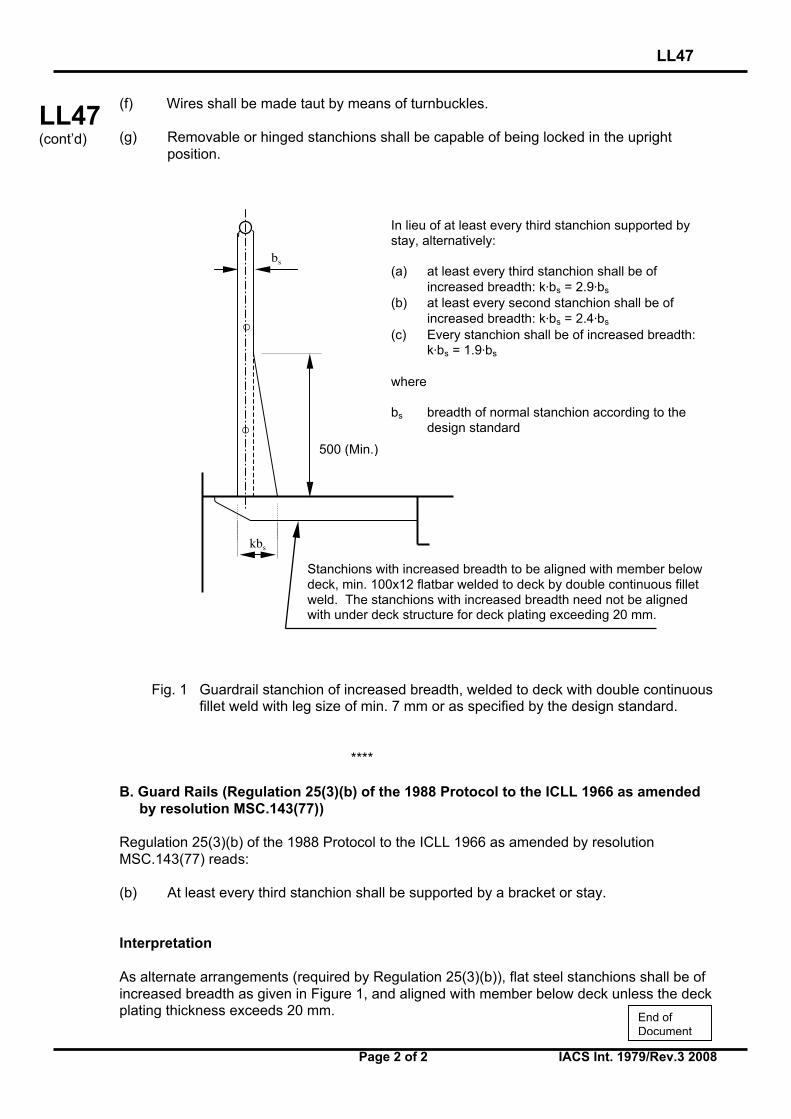
As alternate arrangements (required by Regulation 25(3)(b)), flat steel stanchions shall be ofincreased breadth as given in Figure 1, and aligned with member below deck unless the deckplating thickness exceeds 20 mm.
In lieu of at least every third stanchion supported bystay, alternatively:
(a) at least every third stanchion shall be ofincreased breadth: k⋅bs = 2.9⋅bs
(b) at least every second stanchion shall be ofincreased breadth: k⋅bs = 2.4⋅bs
(c) Every stanchion shall be of increased breadth:k⋅bs = 1.9⋅bs
where
bs breadth of normal stanchion according to thedesign standard
o
o
500 (Min.)
bs
kbs
Stanchions with increased breadth to be aligned with member belowdeck, min. 100x12 flatbar welded to deck by double continuous filletweld. The stanchions with increased breadth need not be alignedwith under deck structure for deck plating exceeding 20 mm.
Fig. 1 Guardrail stanchion of increased breadth, welded to deck with double continuousfillet weld with leg size of min. 7 mm or as specified by the design standard.
End ofDocument
LL48
Page 1 of 2 IACS Int. 1980/Rev.2 2008
LL48(cont)
Moulded Depth (Regulation 3(5)(c) and 3(9) andFreeboard Calculation (Regulation 40(1))
Discontinuous Freeboard Deck, Stepped Freeboard Deck.
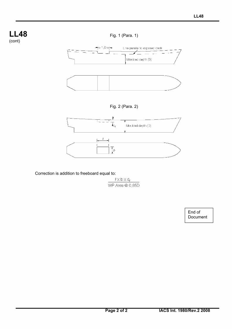
1. Where a step exists in the freeboard deck, creating a discontinuity extending over thefull breadth of the ship, and this step is in excess of one metre in length, Reg 3(9) shall apply.(Fig 1). A step one metre or less in length shall be treated as a recess in accordance withparagraph 2.
2. Where a recess is arranged in the freeboard deck, and this recess does not extend tothe side of the ship, the freeboard calculated without regard to the recess is to be correctedfor the consequent loss of buoyancy. The correction would be equal to the value obtained bydividing the volume of the recess by the waterplane area of the ship at 85% of the leastmoulded depth. (Fig 2).
2.1 The correction would be a straight addition to the freeboard obtained after all othercorrections have been applied, except bow height correction.
2.2 Where the freeboard, corrected for lost buoyancy as above, is greater than theminimum geometric freeboard determined on the basis of a moulded depth measured to thebottom of the recess, the latter value may be used.
3. Recesses in a second deck, designated as the freeboard deck, may be disregarded inthis Interpretation provided all openings in the weather deck are fitted with weathertightclosing appliances.
4. Due regard is to be given to the drainage of exposed recesses and to free surfaceeffects on stability.
5. This Interpretation is not intended to apply to dredgers, hopper barges or other similartypes of ships with large open holds, where each case would require individual consideration.
Footnotes:
1. This UI is also applicable to Regulations 3(5)(c), 3(9) and 40(1) of 1988 Protocol.
2 Paragraph 1 should be replaced with the following sentence: “A step one metre or less inlength shall be treated as a recess in accordance with Reg. 32-1.” when this UI applies tothe revised 1988 Protocol. Paragraphs from 2 to 5 are not applicable to the revised 1988Protocol.
LL48(1980)(Rev.11983)(Rev.2July 2008)
LL48
Page 2 of 2 IACS Int. 1980/Rev.2 2008
LL48(cont)
Fig. 1 (Para. 1)
Fig. 2 (Para. 2)
Correction is addition to freeboard equal to:
End ofDocument
LL49
Page 1 of 1 IACS Int. 1980/Rev.1 2008
LL
(cont)
Air pipe closing devices (Regulation 20)
Where required by Regulation 20 air pipe closing devices shall be weathertight. Closingdevices shall be automatic if, while the vessel is at its draught corresponding to summer loadline, the openings of air pipes to which these closures are fitted submerge at angles up to 40°or up to a lesser angle which may be agreed on the basis of stability requirements. Pressure-vacuum valves (PV valves) may, however, be accepted on tankers.
Wooden plugs and trailing canvas hoses shall not be accepted in position 1 and position 2.
NOTEThe Member Societies in formulating this interpretation realise that pressure-vacuum valves (PVvalves) presently installed on tankers do not theoretically provide complete watertightness. In view,however, of experience of this type of valve and the position in which they are normally fitted it wasconsidered they could be accepted.
Footnotes:
1. This UI is also applicable to Regulation 20 of 1988 Protocol.
2. The first and last sentences of this UI are also applicable to Reg.20(3) of the revised1988 Protocol.
LL49(1980)(Rev.1July 2008)
End ofDocument
LL50
Page 1 of 3 IACS Int. 1982/Rev.5 2008
LL50(cont)
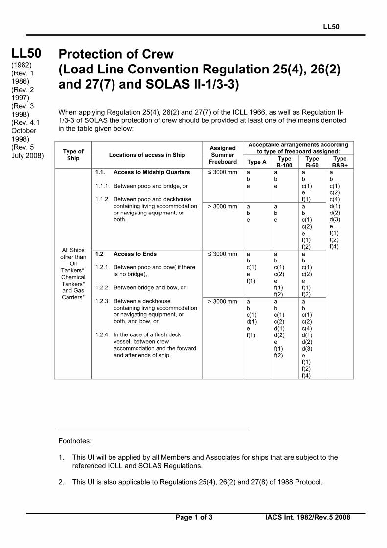
Protection of Crew(Load Line Convention Regulation 25(4), 26(2)and 27(7) and SOLAS II-1/3-3)
When applying Regulation 25(4), 26(2) and 27(7) of the ICLL 1966, as well as Regulation II-1/3-3 of SOLAS the protection of crew should be provided at least one of the means denotedin the table given below:
Acceptable arrangements accordingto type of freeboard assigned:Type of
ShipLocations of access in Ship
AssignedSummer
Freeboard Type ATypeB-100
TypeB-60
TypeB&B+
≤ 3000 mm abe
abe
abc(1)ef(1)
1.1. Access to Midship Quarters
1.1.1. Between poop and bridge, or
1.1.2. Between poop and deckhousecontaining living accommodationor navigating equipment, orboth.
> 3000 mm abe
abe
abc(1)c(2)ef(1)f(2)
≤ 3000 mm abc(1)ef(1)
abc(1)c(2)ef(1)f(2)
abc(1)c(2)ef(1)f(2)
All Shipsother than
OilTankers*,ChemicalTankers*and GasCarriers*
1.2 Access to Ends
1.2.1. Between poop and bow( if thereis no bridge),
1.2.2. Between bridge and bow, or
1.2.3. Between a deckhousecontaining living accommodationor navigating equipment, orboth, and bow, or
1.2.4. In the case of a flush deckvessel, between crewaccommodation and the forwardand after ends of ship.
> 3000 mm abc(1)d(1)ef(1)
abc(1)c(2)d(1)d(2)ef(1)f(2)
abc(1)c(2)c(4)d(1)d(2)d(3)ef(1)f(2)f(4)
abc(1)c(2)c(4)d(1)d(2)d(3)ef(1)f(2)f(4)
Footnotes:
1. This UI will be applied by all Members and Associates for ships that are subject to thereferenced ICLL and SOLAS Regulations.
2. This UI is also applicable to Regulations 25(4), 26(2) and 27(8) of 1988 Protocol.
LL50(1982)(Rev. 11986)(Rev. 21997)(Rev. 31998)(Rev. 4.1October1998)(Rev. 5July 2008)
LL50
Page 2 of 3 IACS Int. 1982/Rev.5 2008
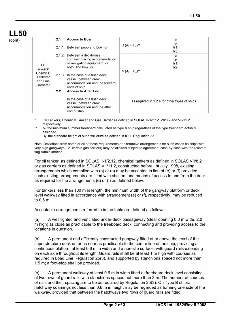
LL50(cont)
≤ (Af + Hs)**
ae
f(1)f(5)
2.1 Access to Bow
2.1.1. Between poop and bow, or
2.1.2. Between a deckhousecontaining living accommodationor navigating equipment, orboth, and bow, or
2.1.3. In the case of a flush deckvessel, between crewaccommodation and the forwardends of ship.
> (Af + Hs)**
ae
f(1)f(2)
OilTankers*,ChemicalTankers*and GasCarriers*
2.2 Access to After End
In the case of a flush deckvessel, between crewaccommodation and the afterend of ship
as required in 1.2.4 for other types of ships
* Oil Tankers, Chemical Tanker and Gas Carrier as defined in SOLAS II-1/2.12, VII/8.2 and VII/11.2respectively
** Af: the minimum summer freeboard calculated as type A ship regardless of the type freeboard actuallyassigned.Hs: the standard height of superstructure as defined in ICLL Regulation 33.
Note: Deviations from some or all of these requirements or alternative arrangements for such cases as ships withvery high gangways (i.e. certain gas carriers) may be allowed subject to agreement case-by-case with the relevantflag Administration.
For oil tanker, as defined in SOLAS II-1/2.12, chemical tankers as defined in SOLAS VII/8.2or gas carriers as defined in SOLAS VII/11.2, constructed before 1st July 1998, existingarrangements which complied with (b) or (c) may be accepted in lieu of (e) or (f) providedsuch existing arrangements are fitted with shelters and means of access to and from the deckas required for the arrangements (e) or (f) as defined below.
For tankers less than 100 m in length, the minimum width of the gangway platform or decklevel walkway fitted in accordance with arrangement (e) or (f), respectively, may be reducedto 0.6 m.
Acceptable arrangements referred to in the table are defined as follows:
(a) A well lighted and ventilated under-deck passageway (clear opening 0.8 m wide, 2.0m high) as close as practicable to the freeboard deck, connecting and providing access to thelocations in question.
(b) A permanent and efficiently constructed gangway fitted at or above the level of thesuperstructure deck on or as near as practicable to the centre line of the ship, providing acontinuous platform at least 0.6 m in width and a non-slip surface, with guard rails extendingon each side throughout its length. Guard rails shall be at least 1 m high with courses asrequired in Load Line Regulation 25(3), and supported by stanchions spaced not more than1.5 m; a foot-stop shall be provided.
(c) A permanent walkway at least 0.6 m in width fitted at freeboard deck level consistingof two rows of guard rails with stanchions spaced not more than 3 m. The number of coursesof rails and their spacing are to be as required by Regulation 25(3). On Type B ships,hatchway coamings not less than 0.6 m in height may be regarded as forming one side of thewalkway, provided that between the hatchways two rows of guard rails are fitted.
LL50
Page 3 of 3 IACS Int. 1982/Rev.5 2008
LL50(cont)
(d) A 10 mm minimum diameter wire rope lifeline supported by stanchions about 10 mapart, orA single hand rail or wire rope attached to hatch coamings, continued and adequatelysupported between hatchways.
(e) A permanent and efficiently constructed gangway fitted at or above the level of thesuperstructure deck on or as near as practicable to the centre line of the ship:- located so as not to hinder easy access across the working areas of the deck;- providing a continuous platform at least 1.0 m in width;- constructed of fire resistant and non-slip material;- fitted with guard rails extending on each side throughout its length; guard rails should be
at least 1.0 m high with courses as required by Regulation 25(3) and supported bystanchions spaced not more than 1.5 m;
- provided with a foot stop on each side;- having openings, with ladders where appropriate, to and from the deck. Openings should
not be more than 40 m apart;- having shelters of substantial construction set in way of the gangway at intervals not
exceeding 45 m if the length of the exposed deck to be traversed exceeds 70 m. Everysuch shelter should be capable of accommodating at least one person and be soconstructed as to afford weather protection on the forward, port and starboard sides.
(f) A permanent and efficiently constructed walkway fitted at freeboard deck level on oras near as practicable to the centre line of the ship having the same specifications as thosefor a permanent gangway listed in (e) except for foot-stops. On Type B ships (certified for thecarriage of liquids in bulk), with a combined height of hatch coaming and fitted hatch cover oftogether not less than 1m in height the hatchway coamings may be regarded as forming oneside of the walkway, provided that between the hatchways two rows of guard rails are fitted.
Alternative transverse locations for (c),(d) and (f) above, where appropriate:(1) At or near centre line of ship; or
Fitted on hatchways at or near centre line of ship.(2) Fitted on each side of the ship.(3) Fitted on one side of the ship, provision being made for fitting on either side.(4) Fitted on one side only.(5) Fitted on each side of the hatchways as near to the centre line as practicable.
Notes:1. In all cases where wire ropes are fitted, adequate devices are to be provided to ensure
their tautness.2. Wire ropes may only be accepted in lieu of guard rails in special circumstances and then
only in limited lengths.3. Lengths of chain may only be accepted in lieu of guard rails if fitted between two fixed
stanchions.4. Where stanchions are fitted, every 3rd stanchion is to be supported by a bracket or stay.5. Removable or hinged stanchions shall be capable of being locked in the upright position.6. A means of passage over obstructions, if any, such as pipes or other fittings of a
permanent nature, should be provided.7. Generally, the width of the gangway or deck-level walkway should not exceed 1.5 m.
End ofDocument
LL51
Page 1 of 1 IACS Int. 1983/Rev.2 2008
LL
(cont)
Freeboards greater than minimum (Regulation2(5))
Where freeboards are required to be increased, because of such consideration as strength(Regulation 1), location of shell doors (Regulation 21) or side scuttles (Regulation 23) or otherreasons then:
(a) the height of- door sills Regulation 12- hatchway coamings Regulation 15(1)- sills of machinery space openings Regulation 17- miscellaneous openings Regulation 18- ventilators Regulation 19- air pipes Regulation 20
(b) the scantlings of hatch covers Regulation 15 and 16,
(c) freeing arrangements Regulation 24 and means for protection of crew Regulation 25,
(d) windows and side scuttles
on the actual freeboard deck may be as required for a superstructure deck, provided thesummer freeboard is such that the resulting draught will not be greater than thatcorresponding to the minimum freeboard calculated from an assumed freeboard decksituated at a distance equal to a standard superstructure height below the actual freeboarddeck. Similar considerations may be given in cases of draught limitation on account of bowheight (Regulation 39).
Footnote: This UI is also applicable to Regulation 2(5) of 1988 Protocol.
LL51(1983)(Rev.11986)(Rev.2July 2008)
End ofDocument
LL52
Page 1 of 1 IACS Int. 1983/Rev.1 2008
LL
(cont)
Weathertight closing appliances for ventilators(Regulation 19(4))
Where required by Regulation 19, weathertight closing appliances for all ventilators inpositions 1 and 2 are to be of steel or other equivalent materials.
Wood plugs and canvas covers are not acceptable in these positions.
Footnote: This UI is also applicable to Regulation 19(4) of 1988 Protocol.
LL52(1983)(Rev.1July 2008)
End ofDocument
LL53
Page 1 of 1 IACS Int. 1987/Rev.1 2008
LL
(cont)
Treatment of moonpools
Where moonpools are arranged within the hull in open communication with the sea, thevolume of the moonpool should not be included in calculation of any hydrostatic properties.An addition should be made to the geometric freeboard, if the moonpool has a larger cross-sectional area above the waterline at 0,85D than below, corresponding to the lost buoyancy.This addition for the excess portion above 0,85D should be made as prescribed for recessesin LL 48/rev 1.
If an enclosed superstructure contains part of the moonpool, deduction should be made fromthe effective length of the superstructure.
Footnotes:
1. This UI is also applicable to 1988 Protocol.
2. The reference “LL 48/rev 1” should be replaced with “Reg.32-1” when this UI applies tothe revised 1988 Protocol.
LL53(1987)(Rev.1July 2008)
End ofDocument
LL54
Page 1 of 1 IACS Int. 1989/Rev.1 2008
LL
(cont)
Effective length of superstructures (Regulation35(3))
When calculating the freeboard for a ship with excessive sheer but without any superstructureat 0,2L amidships, the deduction for sheer per Regulation 38(15) is not to be granted.However, where a poop or forecastle of less than standard height is fitted, when applyingRegulation 35(3), credit may be given to the height of the poop or forecastle by increasing itby the difference between the actual and the standard sheer profiles.
When the height of the superstructure, clear of the slope, is less than the standard height, itseffective length E shall be its length S as obtained from (a)(i), reduced in the ratio of theactual height to the standard height.
Footnote: This UI is also applicable to Regulation 35(3) of the 1988 Protocol.
LL54(1989)(Rev.1July 2008)
End ofDocument
LL55
Page 1 of 1 IACS Int. 1993/Rev.1 2008
LL
(cont)
Least Moulded Depth for a Ship with a Rake ofKeel (Regulation 3(1))
For a ship with a rake of keel, least moulded depth, Dmld, is found by drawing a line parallel tothe keel line of the vessel (including skeg) tangent to the moulded sheer line of the freeboarddeck, as illustrated in the above sketch. The least moulded depth is the vertical distancemeasured from the top of the keel to the top of the freeboard deck beam at side at the pointof tangency.
Depth for freeboard, D, may then be found.
Footnote: This UI is also applicable to Regulation 3(1) of the 1988 Protocol.
LL55(1993)(Rev.1July 2008)
End ofDocument
LL56
Page 1 of 1 IACS Int. 1993/Rev.1 2008
LL
(cont)
Block Coefficient of a Pontoon (Regulation 3(7))
When calculating the block coefficient of a pontoon, according to the definition of Regulation3(7), the 96%-length, if applicable, shall be used disregarding the fact that this might lead to acoefficient greater than 1,0.
Footnote: This UI is also applicable to Regulation 3(7) of the 1988 Protocol.
LL56(1993)(Rev.1July 2008)
End ofDocument
LL57
Page 1 of 1 IACS Int. 1996/Rev.1 2008
LL
(cont)
Block Coefficient of a Multi-hull Craft(Regulation 3(7))
When calculating the block coefficient (Cb) of a multi-hull craft according to the definition ofRegulation 3(7), the full breadth (B) as defined in regulation 3(4) is to be used and not thebreadth of a single hull.
Footnote: This UI is also applicable to Regulation 3(7) of the 1988 Protocol.
LL57(1996)(Rev.1July 2008)
End ofDocument

LL58
Page 1 of 1 IACS Int. 1997/Rev.1 2008
LL
(cont)
Machinery space and emergency generatorroom ventilator coaming heights(Regulations 17(2), 19(3) and 19(4))
Regulation 17(2) requires that the coamings of machinery space ventilators situated inexposed positions on the freeboard and superstructure decks be as high above the deck as isreasonable and practicable.
In general, ventilators necessary to continuously supply the machinery space and, ondemand, immediately supply the emergency generator room should have coamings whichcomply with regulation 19(3), without having to fit weathertight closing appliances.
However, where due to vessel size and arrangement this is not practicable, lesser heights formachinery space and emergency generator room ventilator coamings may be accepted withprovision of weathertight closing appliances in accordance with regulation 19(4) incombination with other suitable arrangements to ensure an uninterrupted, adequate supply ofventilation to these spaces.
Footnote: This UI is also applicable to Regulations 17(2), 19(3) and 19(4) of the 1988Protocol.
LL58(1997)(Rev.1July 2008)
End ofDocument
LL59
Page 1 of 3 IACS Int. 1997/Rev.1 2007
LL59(cont)
Cargo manifold gutter bars - freeingarrangements and intact stability(ICLL Regulation 24(1)(g) and Regulation 26)
ICLL 1988, as amended by res. MSC.143(77), Regulation 24 Freeing Ports
(1)(g) Gutter bars greater than 300 mm in height fitted around the weather decks of tankersin way of cargo manifolds and cargo piping shall be treated as bulwarks. Freeing portsshall be arranged in accordance with this regulation. Closures attached to the freeingports for use during loading and discharge operations are to be arranged in such away that jamming cannot occur while at sea.
ICLL 1966, Regulation 26 Special Conditions of Assignment for Type "A" Ships
Machinery Casings
(1) Machinery casings on Type "A" ships as defined in Regulation 27 shall be protected by anenclosed poop or bridge of at least standard height, or by a deckhouse of equal height andequivalent strength, provided that machinery casings may be exposed if there are noopenings giving direct access from the freeboard deck to the machinery space. A doorcomplying with the requirements of Regulation 12 may, however, be permitted in themachinery casing, provided that it leads to a space or passageway which is as stronglyconstructed as the casing and is separated from the stairway to the engine room by a secondweathertight door of steel or other equivalent material.
Gangway and Access
(2) An efficiently constructed fore and aft permanent gangway of sufficient strength shall befitted on Type "A" ships at the level of the superstructure deck between the poop and themidship bridge or deckhouse where fitted, or equivalent means of access shall be provided tocarry out the purpose of the gangway, such as passages below deck. Elsewhere, and onType "A" ships without a midship bridge, arrangements to the satisfaction of theAdministration shall be provided to safeguard the crew in reaching all parts used in thenecessary work of the ship.
(3) Safe and satisfactory access from the gangway level shall be available between separatecrew accommodations and also between crew accommodations and the machinery space.
Hatchways
(4) Exposed hatchways on the freeboard and forecastle decks or on the tops of expansiontrunks on Type "A" ships shall be provided with efficient watertight covers of steel or otherequivalent material.
Note:
1. Rev.1 of this Unified Interpretation is to be uniformly implemented by all Members andAssociates from 1 July 2008, unless otherwise instructed by a Flag State.
LL59(1997)(Rev.1Dec 2007)
LL59
Page 2 of 3 IACS Int. 1997/Rev.1 2007
LL59(cont)
Freeing Arrangements
(5) Type "A" ships with bulwarks shall have open rails fitted for at least half the length of theexposed parts of the weather deck or other effective freeing arrangements. The upper edgeof the sheer strake shall be kept as low as practicable.
(6) Where superstructures are connected by trunks, open rails shall be fitted for the wholelength of the exposed parts of the freeboard deck.
ICLL 1988, Regulation 26 Special conditions of assignment for type 'A' ships
Machinery casings
(1) Machinery casings on type 'A' ships, as defined in regulation 27, shall be protected byone of the following arrangements:
(a) an enclosed poop or bridge of at least standard height; or
(b) a deckhouse of equal height and equivalent strength.
(2) Machinery casings may, however, be exposed if there are no openings giving directaccess from the freeboard deck to the machinery space. A door complying with therequirements of regulation 12 is acceptable in the machinery casing, provided that itleads to a space or passageway which is as strongly constructed as the casing and isseparated from the stairway to the engine-room by a second weathertight door ofsteel or other equivalent material.
Gangway and access
(3) A fore-and-aft permanent gangway, constructed in accordance with the provisions ofregulation 25-1(2)(e), shall be fitted on type 'A' ships at the level of the superstructuredeck between the poop and the midship bridge or deckhouse where fitted. Thearrangement contained in regulation 25-1(2)(a) is considered an equivalent means ofaccess to carry out the purpose of the gangway.
(4) Safe access from the gangway level shall be available between separate crewaccommodations and also between crew accommodations and the machinery space.
Hatchways
(5) Exposed hatchways on the freeboard and forecastle decks or on the tops ofexpansion trunks on type 'A' ships shall be provided with efficient watertight covers ofsteel or other equivalent material.
Freeing arrangements
(6) Type 'A' ships with bulwarks shall have open rails fitted for at least half the length ofthe weather deck or other equivalent freeing arrangements. A freeing port area, in thelower part of the bulwarks, of 33% of the total area of the bulwarks, is an acceptableequivalent freeing arrangement. The upper edge of the sheer strake shall be kept aslow as practicable.
(7) Where superstructures are connected by trunks, open rails shall be fitted for the wholelength of the exposed parts of the freeboard deck.
LL59
Page 3 of 3 IACS Int. 1997/Rev.1 2007
LL59(cont)
Interpretation
Where gutter bars are installed on the weather decks of tankers in way of cargo manifoldsand are extended aft as far as the after house front for the purpose of containing cargo spillson deck during loading and discharge operations, the free surface effects caused bycontainment of a cargo spill during liquid transfer operations or of boarding seas whileunderway require consideration with respect to the vessel’s available margin of positive initialstability (GMo).
Where the gutter bars installed are greater than 300 mm in height, they are to be treated asbulwarks according to the Load Line Convention with freeing ports arranged in accordancewith Regulation 24 and effective closures provided for use during loading and dischargeoperations. Attached closures are to be arranged in such a way that jamming cannot occurwhile at sea, ensuring that the freeing ports will remain fully effective.
On ships without deck camber, or where the height of the installed gutter bars exceeds thecamber, and for tankers having cargo tanks exceeding 60% of the vessel’s maximum beamat midships regardless of gutter bar height, gutter bars should not be accepted without anassessment of the initial stability (GMo) for compliance with the relevant intact stabilityrequirement taking into account the free surface effect caused by liquids contained by thegutter bars.
End ofDocument

LL60
Page 1 of 2 IACS Int. 1997/Rev.1 2008
LL60(cont)
Freeing ports in way of wells in combinationwith open superstructures(Regulation 24(1) and 24(4))
In the case of vessels having open superstructures on the freeboard or superstructure decks,which open to wells formed by bulwarks on the peripheries of the open decks, the conventionleaves to the satisfaction of the Administration how the freeing port areas for the open spaceswithin the superstructures are to be calculated.
Since water can enter only through the end bulkhead openings, the freeing port areas for theopen spaces within the superstructures should be a function of the breadth of the endopenings and the extent to which wells formed by the open decks and common spaces withinthe open superstructures are covered by the open superstructures.
To determine the minimum freeing port area on each side of the ship for the opensuperstructure (AS) and for the open well (AW), the following procedure is recommended:
1. Determine the total well length (lt) equal to the sum of the length of the open deckenclosed by bulwarks (lW) and the length of the common space within the opensuperstructure (lS).
2. To determine (AS):
2.1 Calculate the freeing port area (A) required for an open well of length lt in accordancewith regulation 24(1) with standard height bulwark assumed.
2.2 Multiply by the factor of 1.5 to correct for the absence of sheer, if applicable, inaccordance with regulation 24(2).
2.3 Multiply by the factor (bO/lt) to adjust the freeing port area for the breadth (bO) of theopenings in the end bulkhead of the enclosed superstructure. (Note: this cancels the ltterms from the calculation.)
2.4 To adjust the freeing port area for that part of the entire length of the well which isenclosed by the open superstructure, multiply by the factor:
1-(lW/lt)2
where lW and lt are defined in 1 above.
2.5 To adjust the freeing port area for the distance of the well deck above the freeboarddeck, multiply by the factor:
0.5 (hS/hW )
where hW is the distance of the well deck above the freeboard deck and hs is onestandard superstructure height.
Footnote: This UI is also applicable to Regulation 24(1) and 24(4) of the 1988 Protocol.
LL60(1997)(Corr.1April1998)(Rev.1July 2008)
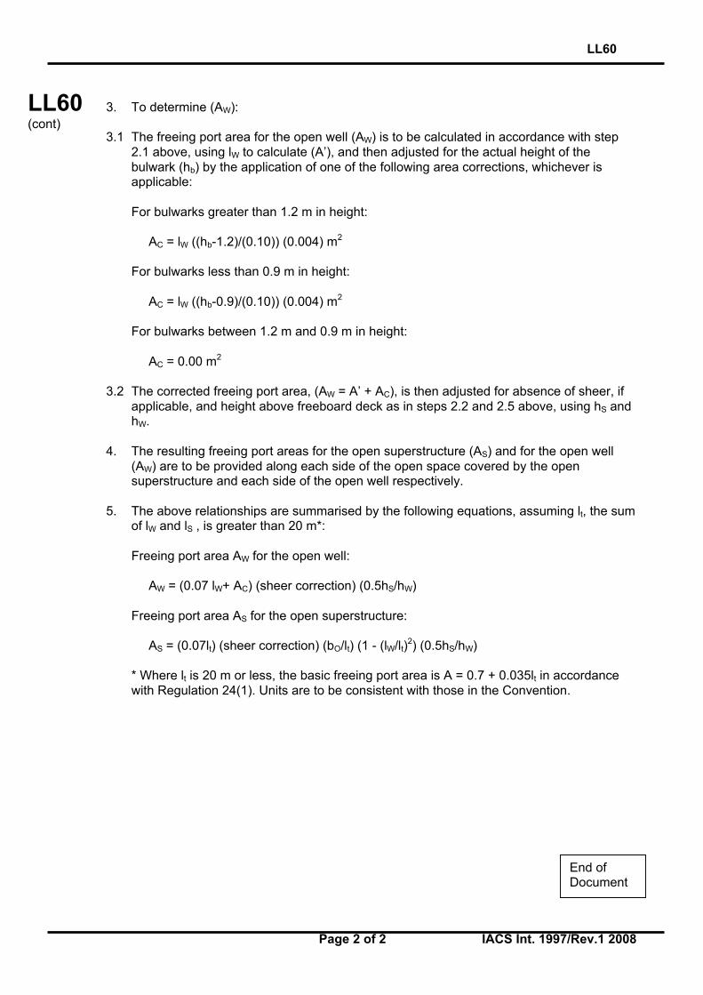
LL60
Page 2 of 2 IACS Int. 1997/Rev.1 2008
LL60(cont)
3. To determine (AW):
3.1 The freeing port area for the open well (AW) is to be calculated in accordance with step2.1 above, using lW to calculate (A’), and then adjusted for the actual height of thebulwark (hb) by the application of one of the following area corrections, whichever isapplicable:
For bulwarks greater than 1.2 m in height:
AC = lW ((hb-1.2)/(0.10)) (0.004) m2
For bulwarks less than 0.9 m in height:
AC = lW ((hb-0.9)/(0.10)) (0.004) m2
For bulwarks between 1.2 m and 0.9 m in height:
AC = 0.00 m2
3.2 The corrected freeing port area, (AW = A’ + AC), is then adjusted for absence of sheer, ifapplicable, and height above freeboard deck as in steps 2.2 and 2.5 above, using hS andhW.
4. The resulting freeing port areas for the open superstructure (AS) and for the open well(AW) are to be provided along each side of the open space covered by the opensuperstructure and each side of the open well respectively.
5. The above relationships are summarised by the following equations, assuming lt, the sumof lW and lS , is greater than 20 m*:
Freeing port area AW for the open well:
AW = (0.07 lW+ AC) (sheer correction) (0.5hS/hW)
Freeing port area AS for the open superstructure:
AS = (0.07lt) (sheer correction) (bO/lt) (1 - (lW/lt)2) (0.5hS/hW)
* Where lt is 20 m or less, the basic freeing port area is A = 0.7 + 0.035lt in accordancewith Regulation 24(1). Units are to be consistent with those in the Convention.
End ofDocument
LL61
Page 1 of 3 IACS Int. 1997/Rev.1 2008
LL61(cont)
Method of correction for the effect of freesurface of liquids in tanks (Regulation 10(2), URL3 and UI LL45)
1 For all loading conditions, the initial metacentric height and the righting lever curveshould be corrected for the effect of free surfaces of liquids in tanks.
2 Free surface effects will exist whenever the filling level in a tank is less than 100% andgreater than 0%. Where the total free surface effects of nominally full (i.e. 98% or above)tanks is small in relation to the metacentric height of the vessel, with the agreement of theadministration the effects for such tanks may be ignored. Free surface effects should beconsidered whenever the filling level in a tank is less than 98%.
3 Tanks which are taken into consideration when determining the free surfacecorrection may be in one of two categories:
3.1 Tanks with filling levels fixed (e.g. liquid cargo, water ballast). The free surfacecorrection should be determined for the actual filling level to be used in each tank.
3.2 Tanks with filling levels variable (e.g. consumable liquids such as fuel oil, diesel oil,and fresh water, and also liquid cargo and water ballast during liquid transfer operations).Except as permitted in 5 and 6, the free surface correction should be the maximum valueattainable between the filling limits envisaged for each tank, consistent with any operatinginstructions.
4 In calculating the free surface effects in tanks containing consumable liquids, it shouldbe assumed that for each type of liquid at least one transverse pair or a single centreline tankhas a free surface and the tank or combination of tanks taken into account should be thosewhere the effect of free surfaces is the greatest.
5 Where water ballast tanks, including anti-rolling tanks and anti-heeling tanks, are to befilled or discharged during the course of a voyage, the free surface effects should becalculated to take account of the most onerous transitory stage relating to such operations.
6 For vessels engaged in liquid transfer operations, the free surface corrections at anystage of the liquid transfer operations may be determined in accordance with the filling levelin each tank at that stage of the transfer operation.
7 The corrections to the initial metacentric height and to the righting lever curve shouldbe addressed separately as follows:
7.1 In determining the correction to initial metacentric height, the transverse moments ofinertia of the tanks should be calculated at 0 degrees angle of heel according to thecategories indicated in 3.
Footnote: This UI is also applicable to Regulation 10(2) of the 1988 Protocol and the revised1988 Protocol.
LL61(1997)(Rev.1July 2008)
LL61
Page 2 of 3 IACS Int. 1997/Rev.1 2008
LL61(cont)
7.2 The righting lever curve may be corrected by any of the following methods subject tothe agreement of the Administration:
.1 Correction based on the actual moment of fluid transfer for each angle of heelcalculated.
.2 Correction based on the moment of inertia, calculated at 0 degrees angle of heel,modified at each angle of heel calculated, (i.e.: GG1sinθ).
.3 Correction based on the summation of Mfs values for all tanks taken intoconsideration, see 8.
With the exception of item 7.2.3 above, corrections may be calculated according to thecategories indicated in 3.
Whichever method is selected for correcting the righting lever curve, only that method shouldbe presented in the vessel's stability booklet. However, where an alternative method isdescribed for use in manually calculating loading conditions, an explanation of the differenceswhich may be found in the results, as well as an example correction for each alternative,should be included.
8 The values of Mfs for each tank may be derived from the formula:
δρkvbMfs =
where:
Mfs is the free surface moment at any inclination in metre-tonnesv is the tank total capacity in cubic metresb is the tank maximum breadth in metresρ is the mass density of liquid in the tank in tonnes/cubic metreδ is equal to v/blh (the tank block coefficient)h is the tank maximum height in metresl is the tank maximum length in metresk is the dimensionless coefficient to be determined from the following table according to
the ratio b/h. The intermediate values are determined by interpolation.
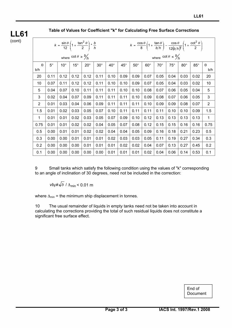
LL61
Page 3 of 3 IACS Int. 1997/Rev.1 2008
LL61(cont)
Table of Values for Coefficient "k" for Calculating Free Surface Corrections
h
bk *
2
tan1
12
sin 2
+=
θθ
( )
+−
+=
2
cot1
12
costan1
8
cos 2
2
θθθθ
hbhbk
where hb≥θcot where h
b≤θcot
θb/h
5° 10° 15° 20° 30° 40° 45° 50° 60° 70° 75° 80° 85° θb/h
20 0.11 0.12 0.12 0.12 0.11 0.10 0.09 0.09 0.07 0.05 0.04 0.03 0.02 20
10 0.07 0.11 0.12 0.12 0.11 0.10 0.10 0.09 0.07 0.05 0.04 0.03 0.02 10
5 0.04 0.07 0.10 0.11 0.11 0.11 0.10 0.10 0.08 0.07 0.06 0.05 0.04 5
3 0.02 0.04 0.07 0.09 0.11 0.11 0.11 0.10 0.09 0.08 0.07 0.06 0.05 3
2 0.01 0.03 0.04 0.06 0.09 0.11 0.11 0.11 0.10 0.09 0.09 0.08 0.07 2
1.5 0.01 0.02 0.03 0.05 0.07 0.10 0.11 0.11 0.11 0.11 0.10 0.10 0.09 1.5
1 0.01 0.01 0.02 0.03 0.05 0.07 0.09 0.10 0.12 0.13 0.13 0.13 0.13 1
0.75 0.01 0.01 0.02 0.02 0.04 0.05 0.07 0.08 0.12 0.15 0.15 0.16 0.16 0.75
0.5 0.00 0.01 0.01 0.02 0.02 0.04 0.04 0.05 0.09 0.16 0.18 0.21 0.23 0.5
0.3 0.00 0.00 0.01 0.01 0.01 0.02 0.03 0.03 0.05 0.11 0.19 0.27 0.34 0.3
0.2 0.00 0.00 0.00 0.01 0.01 0.01 0.02 0.02 0.04 0.07 0.13 0.27 0.45 0.2
0.1 0.00 0.00 0.00 0.00 0.00 0.01 0.01 0.01 0.02 0.04 0.06 0.14 0.53 0.1
9 Small tanks which satisfy the following condition using the values of "k" correspondingto an angle of inclination of 30 degrees, need not be included in the correction:
min/ Δδρkvb < 0.01 m
where Δmin = the minimum ship displacement in tonnes.
10 The usual remainder of liquids in empty tanks need not be taken into account incalculating the corrections providing the total of such residual liquids does not constitute asignificant free surface effect.
End ofDocument
LL62
Page 1 of 2 IACS Int. 1997/Rev.1 2008
LL62 (cont)
Side Scuttles, Windows and Skylights (Regulation 23) (1) Side scuttles and windows together with their glasses, deadlights1 and storm covers, if fitted, shall be of approved design and substantial construction in accordance with, or equivalent to, recognised national or international standards. Non-metallic frames are not acceptable. (2) Side scuttles are defined as being round, or oval, openings with an area not exceeding 0.16 square metres. Round or oval openings having areas exceeding 0.16 square metres shall be treated as windows. (3) Windows are defined as being rectangular openings generally, having a radius at each corner relative to the window size in accordance with recognised national or international standards, and round, or oval, openings with an area exceeding 0.16 square metres. (4) Side scuttles to the following spaces shall be fitted with efficient hinged inside deadlights: (a) spaces below freeboard deck (b) spaces within the first tier of enclosed superstructures (c) first tier deckhouses on the freeboard deck protecting openings leading below or
considered buoyant in stability calculations. The deadlights shall be capable of being effectively closed and secured watertight if fitted below freeboard deck and weathertight if fitted above. (5) Side scuttles shall not be fitted in such a position that their sills are below a line drawn parallel to the freeboard deck at side and having its lowest point 2.5 percent of the breadth B, or 500 mm, whichever is the greatest distance, above the summer load line (or timber summer load line if assigned). (6) Side scuttles shall be of the non-opening type in ships subject to damage stability regulations, if calculations indicate that they would become immersed by any intermediate stage of flooding or the final equilibrium waterplane in any required damage case. (7) Windows shall not be fitted below the freeboard deck, in the first tier end bulkheads or sides of enclosed superstructures and in first tier deckhouses2 considered buoyant in the stability calculations or protecting openings leading below. _____________________________ 1 ‘Deadlights’, in accordance with recognised standards, are fitted to the inside of windows and side scuttles while ‘storm covers’, of comparable specifications to deadlights, are fitted to the outside of windows, where accessible, and may be hinged or portable. 2 Two members reserved their position for those cases where this first tier is not considered buoyant, provided efficient deadlights are fitted. Footnotes: 1. This UI is also applicable to Regulation 23 of the 1988 Protocol. 2. Paragraph 7 of this UI is applicable to Reg. 23(7)(c) of the revised 1988 Protocol. 3. Paragraph 11 of this UI is applicable to Reg. 23(11) of the revised 1988 Protocol.
LL62 (1997) (Rev.1 July 2008) (Corr.1 Aug 2010)
IACS Int. 1997/Corr.1 2010

LL62
Page 2 of 2 IACS Int. 1997/Rev.1 2008
LL62 (cont)
(8) Side scuttles and windows at the side shell in the second tier, protecting direct access below or considered buoyant in the stability calculations, shall be provided with efficient hinged inside deadlights capable of being effectively closed and secured weathertight. (9) Side scuttles and windows set inboard from the side shell in the second tier, protecting direct access below to spaces listed in paragraph (4), shall be provided with either efficient hinged inside deadlights or, where they are accessible, permanently attached external storm covers of approved design and of substantial construction and capable of being effectively closed and secured weathertight. (10) Cabin bulkheads and doors in the second tier separating side scuttles and windows from a direct access leading below may be accepted in place of deadlights or storm covers fitted to the side scuttles and windows. (11) Deckhouses situated on a raised quarter deck or on the deck of a superstructure of less than standard height or on the deck of a deckhouse of less than standard height, may be regarded as being in the second tier as far as the provision of deadlights is concerned, provided the height of the raised quarter deck, superstructure or deckhouse is equal to, or greater than, the standard quarter deck height. (12) Fixed or opening skylights shall have glass thickness appropriate to their size and position as required for side scuttles and windows. Skylight glasses in any position shall be protected from mechanical damage and where fitted in positions 1 or 2, shall be provided with robust deadlights or storm covers permanently attached.
End of Document

LL63
Page 1 of 3 IACS Int. 1998/Rev.2 2008
LL63(cont)
Treatment of steps and recesses in transversesubdivision bulkheads: IMO Res. A.320 (IX),paragraphs 12(d) and 12(e), and Regulation27(12)(d) and (e), Revised 1988 ICLL (MSC.143(77))
Regulation 27, paragraphs 12(d) of 1988 ICLL as amended by Res. MSC.143(77) reads:“Except where otherwise required by paragraph (10)(a), the flooding shall be confined to asingle compartment between adjacent transverse bulkheads, provided that the innerlongitudinal boundary of the compartment is not in a position within the transverse extent ofassumed damage. Transverse boundary bulkheads of wing tanks, which do not extend overthe full breadth of the ship shall be assumed not to be damaged, provided that they extendbeyond the transverse extent of assumed damage prescribed in subparagraph (b). If in atransverse bulkhead there are steps or recesses of not more than 3 m in length, locatedwithin the transverse extent of assumed damage as defined in subparagraph (b), suchtransverse bulkhead may be considered intact and the adjacent compartment may befloodable singly. If, however, within the transverse extent of assumed damage there is a stepor recess of more than 3 m in length in a transverse bulkhead, the two compartmentsadjacent to this bulkhead shall be considered as flooded. The step formed by the afterpeakbulkhead and the afterpeak tank top shall not be regarded as a step for the purpose of thisregulation.”
Regulation 27, paragraphs 12(e) of 1988 ICLL as amended by Res. MSC.143(77) reads:“Where a main transverse bulkhead is located within the transverse extent of assumeddamage and is stepped in way of a double bottom or side tank by more than 3 m, the doublebottom or side tanks adjacent to the stepped portion of the main transverse bulkhead shall beconsidered as flooded simultaneously. If this side tank has openings into one or severalholds, such as grain feeding holes, such hold or holds shall be considered as floodedsimultaneously. Similarly, in a ship designed for the carriage of fluid cargoes, if a side tankhas openings into adjacent compartments, such adjacent compartments shall be consideredas empty and as being flooded simultaneously. This provision is applicable even where suchopenings are fitted with closing appliances, except in the case of sluice valves fitted inbulkheads between tanks and where the valves are controlled from the deck. Manhole coverswith closely spaced bolts are considered equivalent to the unpierced bulkhead, except in thecase of openings in topside tanks making the topside tanks common to the holds.”
Notes:
1. This UI shall be uniformly implemented by all IACS Members and Associates to shipscontracted for construction after 1 January 1999.
2. The “contracted for construction” date means the date on which the contract to build thevessel is signed between the prospective owner and the shipbuilder. For further detailsregarding the date of “contract for construction”, refer to IACS Procedural Requirement(PR) No. 29.
3. Longitudinal distance of 3.0(m) referred in sub-item (a) and figures 1 to 4 should bereplaced with 3.05(m), when this interpretation applies to Res. A.320.
Footnote: This UI is also applicable to Regulation 27(12)(d) and (e) of the 1988 Protocol.
LL63(July1998)(Rev.1July 2004)(Rev.2July 2008)
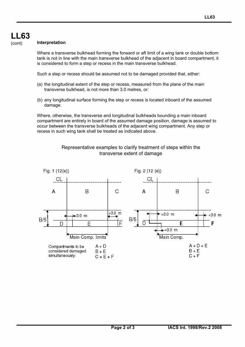
LL63
Page 2 of 3 IACS Int. 1998/Rev.2 2008
LL63(cont) Interpretation
Where a transverse bulkhead forming the forward or aft limit of a wing tank or double bottomtank is not in line with the main transverse bulkhead of the adjacent in board compartment, itis considered to form a step or recess in the main transverse bulkhead.
Such a step or recess should be assumed not to be damaged provided that, either:
(a) the longitudinal extent of the step or recess, measured from the plane of the maintransverse bulkhead, is not more than 3.0 metres, or:
(b) any longitudinal surface forming the step or recess is located inboard of the assumeddamage.
Where, otherwise, the transverse and longitudinal bulkheads bounding a main inboardcompartment are entirely in board of the assumed damage position, damage is assumed tooccur between the transverse bulkheads of the adjacent wing compartment. Any step orrecess in such wing tank shall be treated as indicated above.
Representative examples to clarify treatment of steps within thetransverse extent of damage
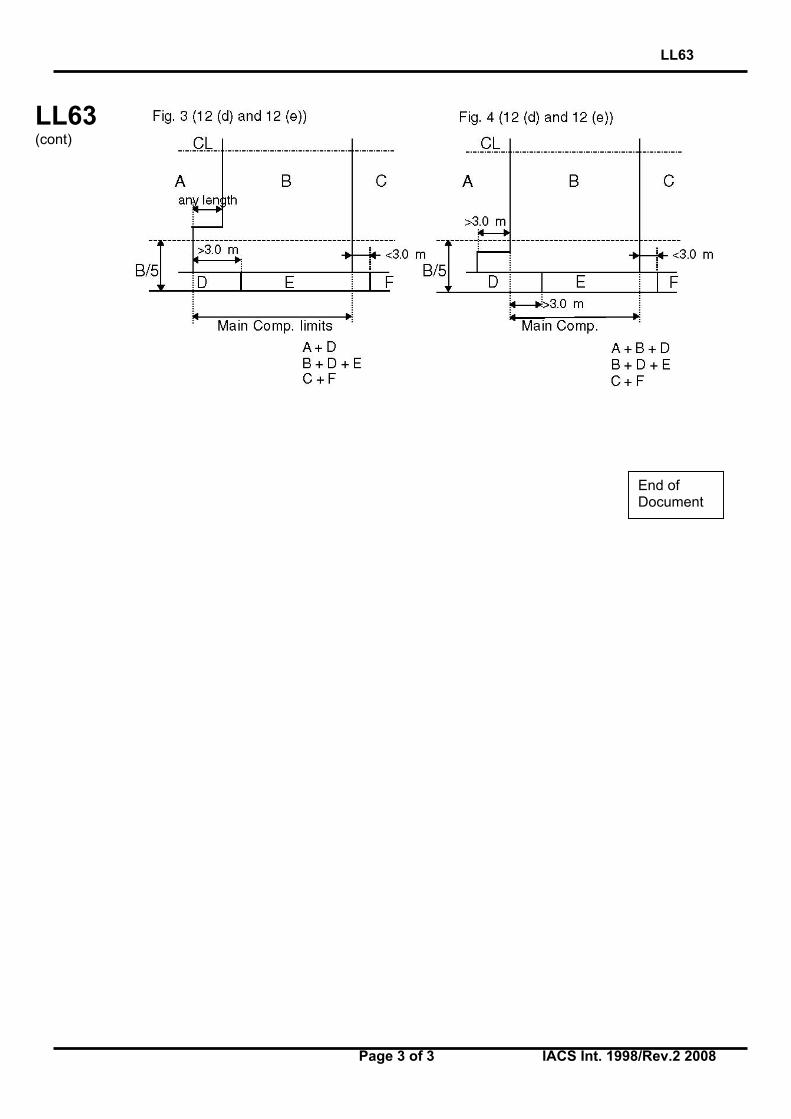
LL63
Page 3 of 3 IACS Int. 1998/Rev.2 2008
LL63(cont)
End ofDocument
LL64
Page 1 of 2 IACS Int. 1998/Rev.5 2008
LL64(cont)
Non-weathertight hatch covers abovesuperstructure deck(Load Line Convention 1966 Regulations 2(5)and 14(2))
The requirements for coaming height and weathertightness of hatch covers located above thesuperstructure deck are left to the satisfaction of the flag Administration by Regulations 2(5)and 14(2) of the Load Line Convention. Exposed coamings and hatch covers situated abovethe second tier of the superstructure, or equivalent, or above the third tier, or equivalent, inthe forward quarter of the ship's length, may be regarded to be above the superstructure deckin the application of 14(2). Non-weathertight covers in these locations may be acceptedsubject to the approval of the flag Administration and conditional upon the following:
1. Their acceptance should be limited to use on container ships.
2. They may be fitted to hatchways located on weatherdecks which are at least twostandard superstructure heights above an actual freeboard deck or an assumed freeboarddeck from which a freeboard can be calculated which will result in a draught not less than thatcorresponding to the freeboard actually assigned. Where any part of a hatchway is forward ofa point located one quarter of the ship's length (0.25L) from the forward perpendicular, thathatchway is to be located on a weatherdeck at least three standard superstructure heightsabove the actual or assumed freeboard deck. It is to be noted that the assumed freeboarddeck is used only for the purpose of measuring the height of the deck on which thehatchways are situated and may be an imaginary, or virtual deck and in this case is not to beused for the actual assignment of freeboard. The vessels freeboard is to be assigned from anactual deck, designated as the freeboard deck, which is to be determined in accordance withthe Convention and LL39.
3. The hatchway coamings should be not less than 600 mm in height.
4. The non-weathertight gaps between hatch cover panels should be considered asunprotected openings with respect to the requirements of intact and damage stabilitycalculations. They should be as small as possible commensurate with the capacity of thebilge system and expected water ingress, and the capacity and operational effectiveness ofthe fire-fighting system and, generally, should not exceed 50 mm.
Notes:
1. This Unified Interpretation is to be uniformly implemented by all Members and Associatesfrom 1 July 1999, unless otherwise instructed by a Flag State.
2. Changes introduced in Rev.3 are to be uniformly implemented by IACS Members andAssociates from 1 January 2002.
3. Changes introduced in Rev.4 are to be uniformly implemented by IACS Members andAssociate from 1 January 2006.
Footnote: This UI is also applicable to Regulations 2(5) and 14(2) of the 1988 Protocol andthe revised 1988 Protocol.
LL64(December1998)(Rev.1,March1999)(Rev.2June 2000)(Rev.3 July2001)(Rev.4 July2005)(Rev.5 July2008)
LL64
Page 2 of 2 IACS Int. 1998/Rev.5 2008
LL64(cont)
5. Labyrinths, gutter bars, or equivalents should be fitted proximate to the edges of eachpanel in way of the gaps to minimise the amount of water that can enter the container holdfrom the top surface of each panel.
6. Scantlings of the hatch cover panels are to be equivalent to those for weathertightcovers and in accordance with the applicable requirements of UR S21 and UI LL70. Thedetails on the securing arrangements to the vessel’s support structure and coamings areprovided in IACS Recommendation No. 14.
7. Bilge alarms should be provided in each hold fitted with non-weathertight covers.
End ofDocument
LL65
Page 1 of 1 IACS Int. 2000/Rev.2 2008
LL65(cont)
Ships with assigned or reassigned reducedfreeboards and intended to carry deck cargo(SOLAS, Chapter II-1, Regulation 4, footnotes .6 and .7)
“Cargo ships shown to comply with the following regulations may be excluded from theapplication of part B-1:
.6 Damage stability requirements of regulation 27 of the 1966 Load Lines Convention asapplied in compliance with resolutions A.320(IX) and A.514(13), provided that in the case ofcargo ships to which regulation 27(9) applies, main transverse watertight bulkheads, to beconsidered effective, are spaced according to paragraph (12)(f) of resolution A.320(IX),except ships intended for the carriage of deck cargo; and
.7 Damage stability requirements of regulation 27 of the 1988 Load Lines Protocol, exceptships intended for the carriage of deck cargo”.
General:
1. This UI pertains to ships intended to carry deck cargo and assigned or reassignedreduced freeboards in accordance with Regulation 27 of the International Conventionon Load Lines, 1966 (ICLL 1966) or the ICLL 1966 as amended by the 1988 Protocol.
2. In .6 and .7 of the footnotes to SOLAS Chapter II-1, Regulation 4, ships shown tocomply with ICLL 1966 Regulation 27 as applied in compliance with IMO Res. A.320and A.514, may be excluded from the application of SOLAS Chapter II-1 Part B-1,except if they carry deck cargo.
3. Therefore ships identified in item 1), above, shall:
a) according to the assigned reduced freeboards, comply with damage stabilityrequirements of Regulation 27 of ICLL 1966 and the 1988 Protocol to the ICLL1966; and
b) according to the intended deck cargo capacity, be provided with the limitingGM or KG curve required by SOLAS Chapter II-1, Regulation 5-1.4 incompliance with the probabilistic damage stability analysis of SOLAS ChapterII-1 Part B-1.
4. The KG used for demonstrating compliance with the criteria in 3 a) shall be the sameas that used for the criteria in 3 b) at the deepest subdivision load line.
Notes:
1. This UI LL 65 is to be uniformly implemented by IACS Members and Associatesfrom 1 July 2001.
2. Revision 1 is to be uniformly implemented by IACS Members and Associates from1 January 2009.
Footnote: This UI is also applicable to the revised 1988 Protocol.
LL65(June2000)(Rev.1June2007)(Rev.2July 2008)
End ofDocument
Hatch Cover Stress/Deflection Calculation(Res. MSC.143(77), 2005 LL Protocol Regulation 16(5) (a) & (b))
Regulation 16 Hatchways closed by weathertight covers of steel or other equivalent materials
Hatch cover minimum design loads
(5) All hatch covers shall be designed such that:
(a) the product of the maximum stress determined in accordance with the above loads and the factor of 1.25 does not exceed the minimum upper yield point strength of the material in tension and the critical buckling strength in compression;
(b) the deflection is limited to not more than 0.0056 times the span,
Interpretation
In the calculation of stress and deflection from the prescribed mass per unit area, thedesign pressure is to be determined by using a vertical acceleration equal to 1.0g.
Note: This UI LL 66 is to be uniformly implemented by IACS Members and Associates from 1 January 2005.
LL66(Oct2003)
LL66
IACS Interpretations 2003
▼▼
66-1

Endorsement of Certificates with the Date of Completion of the Survey on which theyare Based
“Resolutions MSC.170(79), MSC.171(79), MSC.172(79), MSC.174(79) throughMSC.179(79) and MSC.181(79) through MSC.187(79) require that the identifiedcertificates include the statement:
"Completion date of the survey on which this certificate is based: dd/mm/yyyy".
Interpretation
For application of the above resolutions, the following IACS UnifiedInterpretation applies:
The “Completion date of the survey on which this certificate is based”, is the date ofthe last initial/renewal survey visit on which all statutory and class items, required tobe surveyed, have been surveyed (regardless if they were found satisfactory or withminor deficiency).
Note:
1. This UI is to be uniformly implemented by IACS Members and Associates from 1 March 2004.
2. Revision 1 of this UI is to be uniformly implemented by IACS Members and Associates from 1 July 2006.
SC183(Nov 2003)(Rev.1, Nov.2005)
LL67(Nov 2003)(Rev.1, Nov.2005)
MPC10(Nov 2003)(Rev.1, Nov.2005)
LL67
IACS Interpretations 2003/Rev.1 200567-1
▼▼
LL68
Page 1 of 1 IACS Int. 2004/Rev.1 2008
LL
(cont)
Position of Freeboard Deck on Float On/FloatOff Barge Carriers(Regulation 3(9))
Reg.3(9):“Freeboard Deck. The freeboard deck is normally the uppermost complete deck exposed toweather and sea, which has permanent means of closing all openings in the weather partthereof, and below which all openings in the sides of the ship are fitted with permanentmeans of watertight closing. In a ship having a discontinuous freeboard deck, the lowest lineof the exposed deck and the continuation of that line parallel to the upper part of the deck istaken as the freeboard deck. At the option of the owner and subject to the approval of theAdministration, a lower deck may be designated as the freeboard deck provided it is acomplete and permanent deck continuous in fore and aft direction at least between themachinery space and peak bulkheads and continuous athwartships. When this lower deck isstepped the lowest line of the deck and the continuation of that line parallel to the upper partof the deck is taken as the freeboard deck. When a lower deck is designated as the freeboarddeck, that part of the hull which extends above the freeboard deck is treated as asuperstructure so far as concerns the application of the conditions of assignment and thecalculation of freeboard. It is from this deck that the freeboard is calculated.”
Interpretation:
1. Float On/Float Off Barge Carriers are designed to be ballasted such that the bottom oftheir cargo space(s) (well deck) submerges below the waterline to allow barges beingfloated in and out.
2. If such a ship is fitted with weathertight closures for the cargo space(s) and awatertight enclosure at the stern, the uppermost complete deck may be taken as thefreeboard deck.
3. If such a ship is not fitted with weathertight closures for the cargo space(s) or awatertight enclosure at the stern, the well deck shall be taken as the freeboard deck,while buoyant spaces above may be considered as superstructures in accordancewith UI LL 15 or 88 Prot. Reg. 34(1).
4. If such a ship is not fitted with weathertight closures for the cargo space(s) but has awatertight enclosure at the stern, the uppermost complete deck may be taken as thefreeboard deck provided that:
- the structure of the freeboard deck complies with the requirements of LL39;- the calculated freeboard is corrected for any missing buoyancy above the well
deck in accordance with LL48, and- a satisfactory safety level at the resulting draught is demonstrated according to
alternative concepts.
Note: This UI is to be uniformly implemented by IACS Members and Associates from 1 April2005.
Footnote: This UI is also applicable to to Regulation 3(9) of the 1988 Protocol and therevised 1988 Protocol.
LL68(May2004)(Rev.1July 2008)
End ofDocument
LL69
Page 1 of 2 IACS Int. 2004/Rev.1 2008
LL69 (cont)
Interpretation to 1966 ICLL Reg. 27
Reg.27 of ICLL 1966: IMO Res. A.320 paragraph 12:
“Damage Assumptions
(12) The following principles regarding the character of the assumed damage apply:
(a) The vertical extent of damage in all cases is assumed to be from the base line upwardswithout limit.
(b) The transverse extent of damage is equal to B/5 or 11.5 metres (37.7 feet), which ever isthe lesser, measured inboard from the side of the ship perpendicularly to the centre lineat the level of the summer load water line.
(c) If damage of a lesser extent than specified in sub paragraphs (a) and (b) of thisparagraph results in a more severe condition, such lesser extent shall be assumed.
(d) Except where otherwise required by paragraph (10)(a) the flooding shall be confined to asingle compartment between adjacent transverse bulkheads provided the innerlongitudinal boundary of the compartment is not in a position within the transverse extentof assumed damage. Transverse boundary bulkheads of wing tanks, which do not extendover the full breadth of the ship shall be assumed not to be damaged, provided theyextend beyond the transverse extent of assumed damage prescribed in sub paragraph(b) of this paragraph.
If in a transverse bulkhead there are steps or recesses of not more than 3.05 metres (10feet) in length located within the transverse extent of assumed damage as defined insub-paragraph (b) of this paragraph, such transverse bulkhead may be considered intactand the adjacent compartment may be floodable singly. If, however, within the transverseextent of assumed damage there is a step or recess of more than 3.05 metres (10 feet)in length in a transverse bulkhead, the two compartments adjacent to this bulkhead shallbe considered as flooded. The step formed by the after peak bulkhead and the after peaktank top shall not be regarded as a step for the purpose of this Regulation.
Notes:
1. This UI is to be uniformly implemented by IACS Members and Associates from 1 April2005.
2. The distance of 3.05 m referred in this UI should be replaced with 3.00 m, when thisinterpretation applies to the 1988 Protocol and the revised 1988 Protocol.
LL69(May2004)(Rev.1July 2008)

LL69
Page 2 of 2 IACS Int. 2004/Rev.1 2008
LL69 (cont)
(e) Where a main transverse bulkhead is located within the transverse extent of assumeddamage and is stepped in way of a double bottom or side tank by more than 3.05 metres(10 feet), the double bottom or side tanks adjacent to the stepped portion of the maintransverse bulkhead shall be considered as flooded simultaneously. If this side tank hasopenings into one or several holds, such as grain feeding holes, such hold or holds shallbe considered as flooded simultaneously. Similarly in a ship designed for the carriage offluid cargoes, if a side tank has openings into adjacent compartments, such adjacentcompartments shall be considered as empty and flooded simultaneously. This provisionis applicable even where such openings are fitted with closing appliances, except in thecase of sluice valves fitted in bulkheads between tanks and where the valves arecontrolled from the deck. Manhole covers with closely spaced belts are consideredequivalent to the unpierced bulkhead except in the case of openings in topside tanksmaking the topside tanks common to the holds.
(f) Where the flooding of any two adjacent fore and aft compartments is envisaged maintransverse watertight bulkheads shall be spaced at least 1/3L2/3 or 14.5 metres (0.495L2/3
or 47.6 feet), whichever is the lesser, in order to be considered effective. Wheretransverse bulkheads are spaced at a lesser distance, one or more of these bulkheadsshall be assumed as non-existent in order to achieve the minimum spacing betweenbulkheads.”
Interpretation:
Treatment of the volume of the forecastle, which is located over the foremost cargo hold fordamage stability calculation in accordance with Reg.27 of ICLL 1966: IMO Res. A.320paragraph 12.
In the case where the forecastle overlaps foremost cargo hold, provided the forecastlebulkhead is not more than 3.05 m aft of the forward bulkhead of the hold and the deckforming the step in way is watertight, then the bulkhead will be considered as continuous andnot subject to damage.
End ofDocument
Corrosion Margin for Hatch Cover DesignReg. 16 (5)(d), amendments to the Protocol of 1988 relating to the InternationalConvention on Load Lines, 1966 (Res. MSC. 143(77))
Regulation 16 (5) (d) reads:
Hatchways closed by weathertight covers of steel or other equivalent material
All hatch covers shall be designed such that:
(a) the product of the maximum stress determined in accordance with the above loads and the factor of 1.25 does not exceed the minimum upper yield point strength of the material in tension and the critical buckling strength in compression;
(b) the deflection is limited to not more that 0.0056 times the span;
(c) steel plating forming the tops of covers is not less in thickness that 1% of the spacing of stiffeners or 6 mm if that be greater; and
(d) an appropriate corrosion margin is incorporated.
Interpretation
The “appropriate corrosion margin” for hatch covers of cargo holds in position 1 and 2and above, defined as the corrosion addition ts which is to be added to the netthickness tnet required by (a), (b) and (c) is:
1. for Bulk Carriers, Ore Carriers and Combination Carriers, as defined in UR Z11.2:
- single skin hatch covers, a corrosion addition ts = 2.0 mm for all plating and stiffeners;
- double skin hatch covers, a corrosion addition ts = 2.0 mm for top and bottomplating and ts = 1.5 mm for the internal structure.
2. for other vessels:
- single skin hatch covers, a corrosion addition ts = 2.0i) mm for all plating and stiffeners;
- double skin hatch covers, a corrosion addition ts = 1.5i) mm for top and bottom plating and ts = 1.0 mm for the internal structure.
i) Corrosion addition ts = 1.0 mm for the hatch covers in way of cellular cargo holds intended for containers.
LL70(Jan2005)
LL70
IACS Interpretations 200570-1
The above corrosion margins have been defined based on the assumption thatcorrosion protection and renewals as given in UR S21.6.1 is complied with for all shiptypes subject to regulation 16 (5) (d) of the 1988 Load Line Protocol.
For corrosion addition ts = 1.0 mm it is assumed that the thickness for steel renewal istnet and the thickness for coating or annual gauging is tnet + 0,5 mm.
Note: This UI LL70 is to be uniformly implemented by IACS Members and Associates on ships constructed (i.e. keel laid) from 1st January 2005.
END
LL70(C’td)
LL70
70-2
IACS Interpretations 2005
Page 1 of 3
“FAQ”
(Note: This paper is prepared by IACS for external use. 16 August 2005).
Hatch Cover Design for General Cargo Ships and
Container Ships
Question 1
Bulk Carriers
IACS S21 Rev.3 (April 2003) entered into force on 1 January 2004, and applies to ships contracted for construction on or after 1 January 2004.
When the bulk carrier hatch covers are designed according to IACS S21 Rev.3 (April 2003), do they also fulfil the MSC.143 (77) Annex 3 – Regulation 16 requirements?
Answer It is confirmed that when bulk carrier hatch covers are designed according to IACS UR S21 Rev.3 (April 2003), they also fulfil the MSC.143 (77) Annex 3 - Regulation 16 requirements. Question 2
Container Carriers and General Cargo Ships
In Resolution MSC.143 (77) Annex 3 (Adopted on 5 June 2003) – Regulation 16 (5)(d), it is stated that “an appropriate corrosion margin is incorporated’.
Can the same corrosion margin as for the conventional 1.75t/m2 weather
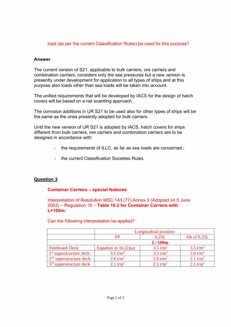
Page 2 of 3
load (as per the current Classification Rules) be used for this purpose?
Answer The current version of S21, applicable to bulk carriers, ore carriers and combination carriers, considers only the sea pressures but a new version is presently under development for application to all types of ships and at this purpose also loads other than sea loads will be taken into account. The unified requirements that will be developed by IACS for the design of hatch covers will be based on a net scantling approach. The corrosion additions in UR S21 to be used also for other types of ships will be the same as the ones presently adopted for bulk carriers. Until the new version of UR S21 is adopted by IACS, hatch covers for ships different from bulk carriers, ore carriers and combination carriers are to be designed in accordance with:
- the requirements of ILLC, as far as sea loads are concerned ;
- the current Classification Societies Rules. Question 3
Container Carriers – special features
Interpretation of Resolution MSC.143 (77) Annex 3 (Adopted on 5 June 2003) – Regulation 16 – Table 16.2 for Container Carriers with L>100m: Can the following interpretation be applied?
Longitudinal position
FP 0.25L Aft of 0.25L L>100m
Freeboard Deck Equation in 16 (2)(a) 3.5 t/m2 3.5 t/m2 1st superstructure deck 3.5 t/m2 3.5 t/m2 2.6 t/m2 2nd superstructure deck 2.6 t/m2 2.6 t/m2 2.1 t/m2 3rd superstructure deck 2.1 t/m2 2.1 t/m2 2.1 t/m2
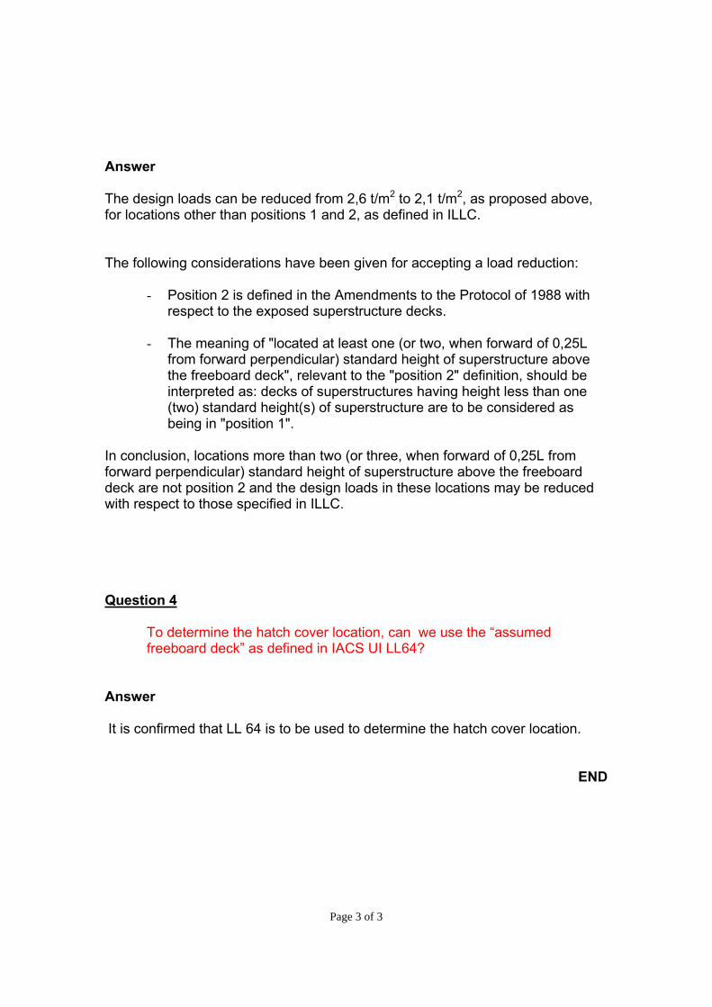
Page 3 of 3
Answer The design loads can be reduced from 2,6 t/m2 to 2,1 t/m2, as proposed above, for locations other than positions 1 and 2, as defined in ILLC. The following considerations have been given for accepting a load reduction:
- Position 2 is defined in the Amendments to the Protocol of 1988 with respect to the exposed superstructure decks.
- The meaning of "located at least one (or two, when forward of 0,25L
from forward perpendicular) standard height of superstructure above the freeboard deck", relevant to the "position 2" definition, should be interpreted as: decks of superstructures having height less than one (two) standard height(s) of superstructure are to be considered as being in "position 1".
In conclusion, locations more than two (or three, when forward of 0,25L from forward perpendicular) standard height of superstructure above the freeboard deck are not position 2 and the design loads in these locations may be reduced with respect to those specified in ILLC. Question 4
To determine the hatch cover location, can we use the “assumed freeboard deck” as defined in IACS UI LL64?
Answer It is confirmed that LL 64 is to be used to determine the hatch cover location.
END
LL71
Page 1 of 1 IACS Int. 2005/Rev.1 2008
LL
(cont)
Similar stage of construction(1966 ILLC, Article 2(6))(amended LL Protocol 1988, regulation 2, paragraphs (7) and (8))
1966 ILLC, Article 2(6):
New ship means a ship the keel of which is laid, or which is at a similar stage of construction,on or after the date of coming into force of the present Convention for each ContractingGovernment.
Amended 1988 LL Protocol, regulation 2, paragraphs (7) and (8):
(7) Unless expressly provided otherwise, the regulations of this Annex shall apply to shipsthe keels of which are laid or which are at a similar stage of construction on or after 1January 2005.
(8) For ships the keels of which are laid or which are at a similar stage of construction before1 January 2005, the Administration shall ensure that the requirements which areapplicable under the International Convention on Load Lines, 1966, as modified by theProtocol of 1988 relating thereto, adopted by the International Conference onHarmonized System of Survey and Certification, 1988, are complied with.
Interpretation:
The term “similar stage of construction” means the stage at which:
- construction identifiable with a specific ship begins; and
- assembly of that ship has commenced comprising at least 50 tonnes or one per cent ofthe estimated mass of all structural material, whichever is less.
Note: This UI LL71 is to be uniformly implemented by IACS Members and Associate from 1July 2005.
Footnote: This UI is also applicable to Article 2(6) of the 1988 Protocol and the revised 1988Protocol.
LL71(April2005)(Rev.1July 2008)
End ofDocument
Interpretation to ICLL Regulation 27
Regulation
Regulation 27(3) reads:
A type "A" ship, if over 150 m in length, and designed to have empty compartmentswhen loaded to her summer load water line, shall be able to withstand the flooding ofany one of these empty compartments at an assumed permeability of 0.95, and remainafloat in a condition of equilibrium considered to be satisfactory by the Administration.In such a ship, if over 225 m in length, the machinery space shall be treated as afloodable compartment but with a permeability of 0,85.
Interpretation
Members apply resolution A.320(IX) when certifying ships of non 1988 Protocol Partiesunder regulations 27(3) of the 1966 ICCL.
Note:This UI is to be uniformly implemented by IACS Members and Associates to shipsconstructed on or after 1 January 2006.
▼
LL72(Sept 2005)
▼
IACS Interpretations 2005 72-1
LL72
LL74
Page 1 of 1 IACS Int. 2008
SC
(cont)
Measurement of Distances
Several IMO instruments (e.g., ICLL, SOLAS and MARPOL Conventions, the IBC Code andthe IGC Code, etc.) require distances to be measured such as tank length, height, width, ship(or subdivision or waterline) length, etc..
Interpretation
Unless explicitly stipulated otherwise in the text of the regulations in SOLAS, Load Line andMARPOL Conventions and any of their mandatory Codes, distances are to be measured byusing moulded dimensions.
Note:
This Unified Interpretation is to be uniformly implemented by IACS Societies from 1 April2009.
SC224(Aug 2008)
LL74(Aug 2008)
MPC95(Aug 2008)
End ofDocument
LL75
Page 1 of 1 IACS Int. 2008/Rev.1 2009
SC
(cont)
Permeability of Store Space in the DamageStability Calculation(Regulation 27(3) & (8.d))
Regulation
1. Reg.27(3) of 1988 protocol of 1966 ICLL and its amendment MSC.143(77) reads:
“(3) A type ‘A’ ship, if over 150 m in length, to which a freeboard less than type ‘B’has been assigned, when loaded in accordance with the requirements of paragraph(11), shall be able to withstand the flooding of any compartment or compartments,with an assumed permeability of 0.95, consequent upon the damage assumptionsspecified in paragraph (12), and shall remain afloat in a satisfactory condition ofequilibrium, as specified in paragraph (13). In such a ship, the machinery space shallbe treated as a floodable compartment, but with a permeability of 0.85.”
2. Reg.27(8.d) of 1988 protocol of 1966 ICLL and its amendment MSC.143(77) reads:
“the ship, when loaded in accordance with the requirements of paragraph (11), shallbe able to withstand the flooding of any compartment or compartments, with anassumed permeability of 0.95, consequent upon the damage assumptions specified inparagraph (12), and shall remain afloat in a satisfactory condition of equilibrium, asspecified in paragraph (13). In such a ship, if over 150 m in length, the machineryspace shall be treated as a floodable compartment, but with a permeability of 0.85.”
Interpretation
The permeability assumed in the damage stability calculation for the flooding of any storespace shall be 0.95 under 1988 Protocol of 1966 ICLL.
Note:
1. This Unified Interpretation is to be uniformly implemented by IACS Members andAssociates for ships contracted for construction on or after 1 July 2009.
2. The “contracted for construction” date means the date on which the contract to buildthe vessel is signed between the prospective owner and the shipbuilder. For furtherdetails regarding the date of “contract for construction”, refer to IACS ProceduralRequirement (PR) No. 29.
LL75(Sept2008)(Rev.1Mar 2009)
End ofDocument

SC234, LL76 and MPC96
Page 1 of 1 IACS Int. 2009/Rev.2 2014
SC234 (cont)
LL76 (cont)
MPC96 (cont)
SC234 (Apr 2009) (Corr.1 Jul 2010) (Rev.1 Feb 2014) (Rev.2 Dec 2014)
LL76 (Apr 2009) (Corr.1 Jul 2010) (Rev.1 Feb 2014) (Rev.2 Dec 2014)
MPC96 (Apr 2009) (Corr.1 Jul 2010) (Rev.1 Feb 2014) (Rev.2 Dec 2014)
Initial Statutory Surveys at New Construction Deleted June 2016.
End of Document
LL77
Page 1 of 2 IACS Int. 2011
LL77(cont)
Application of Load Line Requirements toConversions of Single-hull Oil Tankers toDouble-hull Oil Tankers or Bulk Carriers
Article 10 - Repairs, alterations and modifications
(1) A ship which undergoes repairs, alterations, modifications and outfitting related theretoshall continue to comply with at least the requirements previously applicable to the ship. Anexisting ship in such a case shall not, as a rule, comply to a lesser extent with therequirements for a new ship than it did before.
(2) Repairs, alterations and modifications of a major character and outfitting related theretoshould meet the requirements for a new ship in so far as the administration deemsreasonable and practicable.
Interpretation
1 For single-hull oil tankers converted to double-hull oil tankers:
1.1 The ship should meet the requirements of the regulations contained in chapter III(Freeboards) of Annex I of the Load Line Convention in effect at the date of conversion. Incases where there are no changes to the parameters which result in a change of theminimum freeboard*1, and where there is no decrease in magnitude of freeboard assignedafter conversion, using the Convention previously applicable to the ship in determining anychange or decrease as mentioned above, the converted ship should continue to comply withat least the requirements previously applicable to the ship.
1.2 Any structure and/or equipment such as doors, hatches, and cable lockers, etc., whichis newly added, replaced, or modified is to comply with the requirements of the regulationscontained in chapter II (Conditions of assignment of freeboard) of Annex I of the Conventionin effect at the date of conversion.
2 For single-hull oil tankers converted to bulk carriers:
2.1 Any such conversion should be regarded as a modification of a major character and theship should meet all the requirements of the regulations annexed to the Convention (includingregulation 39) in effect at the date of conversion; and
2.2 Notwithstanding the above, the requirements of the regulations contained in chapter II(Conditions of assignment of freeboard) of Annex I of the Convention in effect at the date ofconversion, should be applied only to the structure and/or equipment, which is newly added,replaced, or modified.
Note
This UI is to be uniformly implemented by IACS Societies to conversions which occur (asdefined in paragraph 3) on or after 1 January 2013.
LL77(Nov2011)
LL77(Dec2011)

LL77
Page 2 of 2 IACS Int. 2011
LL77(cont)
3 The date on which a conversion occurs for the purposes of determining the applicabilityof requirements for ships constructed on or after the date on which any relevant amendmentsenters into force should be:
3.1 the date on which the contract is placed for the conversion; or
3.2 in the absence of a contract, the date on which the work identifiable with the specificconversion begins; or
3.3 the completion date of the conversion*2, if that occurs more than 3 years after the datespecified in subparagraph 3.1 above or 30 months after the date specified in subparagraph3.2 above, either as applicable.
Footnote:
*1 “which result in a change of the minimum freeboard” should be understood as “which are used indetermining the minimum freeboard even though the minimum freeboard has no change in fact”.
*2 Where the completion date of the conversion has been subject to delay beyond the period referred to inparagraph 3.3 above due to unforeseen circumstances beyond the control of the builder and the owner, the otherdates referred to in paragraph 3.1 or 3.2 above, if applicable, may be accepted by the Administration in lieu of thecompletion date of the conversion in accordance with MSC-MEPC.1/Circ.1247.
End ofDocument
MPC104, LL78 and HSC9
Page 1 of 1 IACS Int. 2013/Corr.1 2014
SC260(cont)
MPC104(cont)
LL78(cont)
MLC1(cont)
HSC9(cont)
Keel Laying Date for Fibre-Reinforced Plastic(FRP) Craft
Interpretation
For the purposes of the application of the IMO Conventions and Codes (PerformanceStandards, Technical Standards, Resolutions and Circulars) for Fibre-Reinforced Plastic(FRP) Craft, the term “the keels of which are laid or which are at a similar stage ofconstruction” should be interpreted as the date that the first structural reinforcement of thecomplete thickness of the approved hull laminate schedule is laid either in or on the mould.
NOTE
1. This UI is to be uniformly implemented by IACS Societies from 1 January 2014.
MPC104(Mar2013)(Corr.1Jan 2014)
LL78(Mar2013)(Corr.1Jan 2014)
HSC9(Mar2013)(Corr.1Jan 2014)
End ofDocument
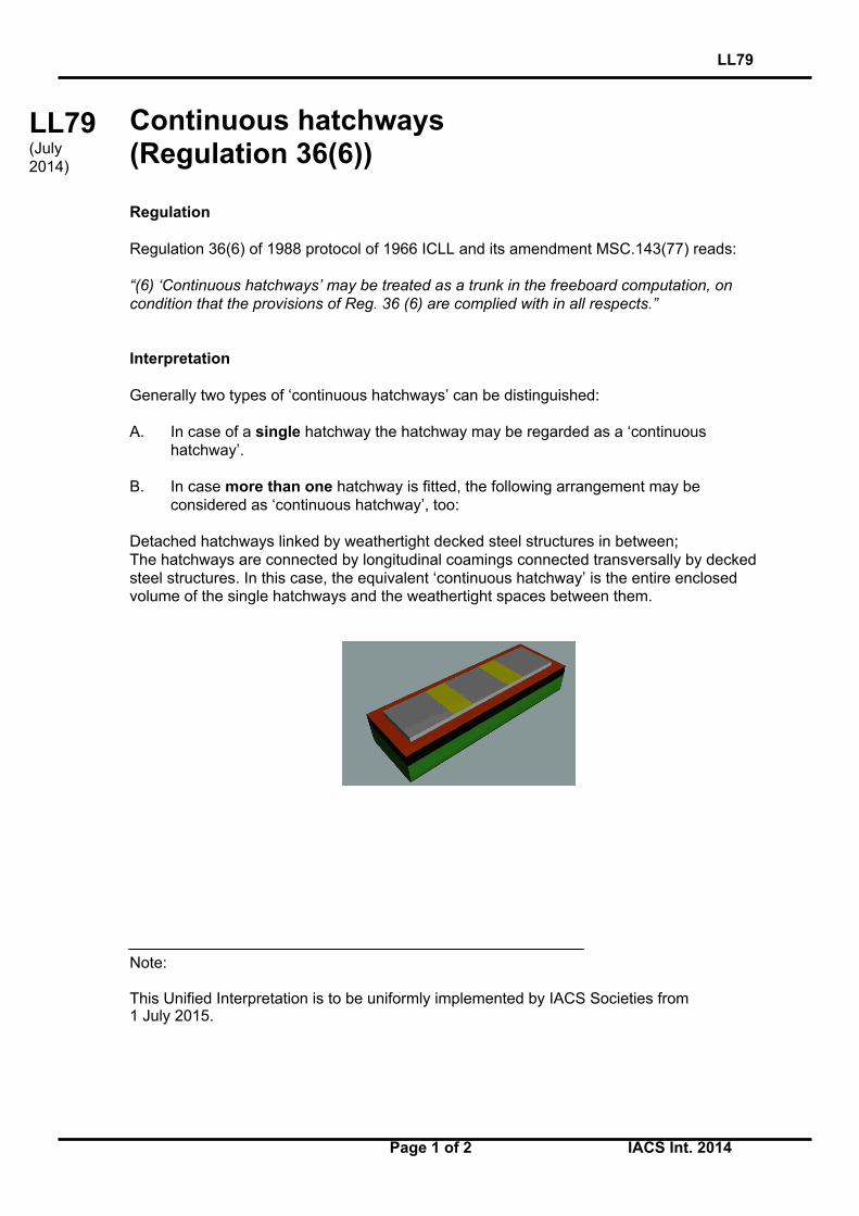
LL79
Page 1 of 2 IACS Int. 2014
LL79(cont)
Continuous hatchways(Regulation 36(6))
Regulation
Regulation 36(6) of 1988 protocol of 1966 ICLL and its amendment MSC.143(77) reads:
“(6) ‘Continuous hatchways’ may be treated as a trunk in the freeboard computation, oncondition that the provisions of Reg. 36 (6) are complied with in all respects.”
Interpretation
Generally two types of ‘continuous hatchways’ can be distinguished:
A. In case of a single hatchway the hatchway may be regarded as a ‘continuous hatchway’.
B. In case more than one hatchway is fitted, the following arrangement may be considered as ‘continuous hatchway’, too:
Detached hatchways linked by weathertight decked steel structures in between;The hatchways are connected by longitudinal coamings connected transversally by deckedsteel structures. In this case, the equivalent ‘continuous hatchway’ is the entire enclosedvolume of the single hatchways and the weathertight spaces between them.
Note:
This Unified Interpretation is to be uniformly implemented by IACS Societies from1 July 2015.
LL79(July2014)
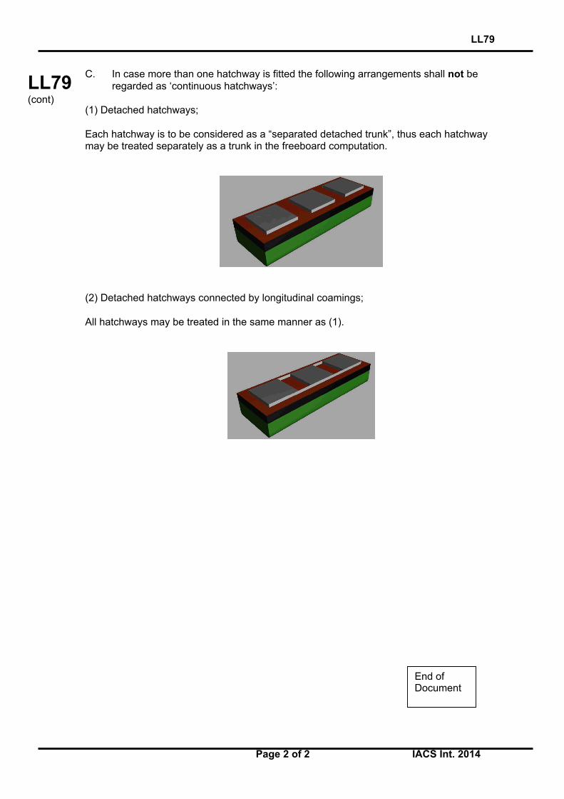
LL79
Page 2 of 2 IACS Int. 2014
LL79(cont)
C. In case more than one hatchway is fitted the following arrangements shall not be regarded as ‘continuous hatchways’:
(1) Detached hatchways;
Each hatchway is to be considered as a “separated detached trunk”, thus each hatchwaymay be treated separately as a trunk in the freeboard computation.
(2) Detached hatchways connected by longitudinal coamings;
All hatchways may be treated in the same manner as (1).
End ofDocument
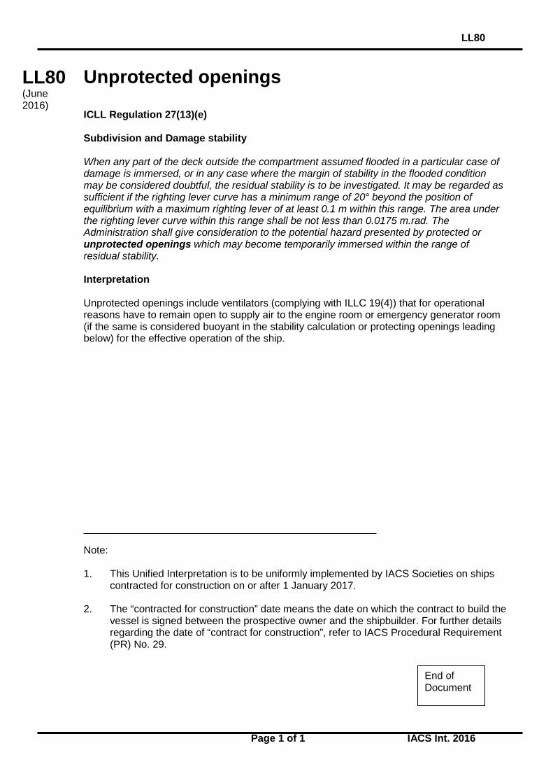
LL80
Page 1 of 1 IACS Int. 2016
LL 80 (cont)
Unprotected openings ICLL Regulation 27(13)(e) Subdivision and Damage stability When any part of the deck outside the compartment assumed flooded in a particular case of damage is immersed, or in any case where the margin of stability in the flooded condition may be considered doubtful, the residual stability is to be investigated. It may be regarded as sufficient if the righting lever curve has a minimum range of 20° beyond the position of equilibrium with a maximum righting lever of at least 0.1 m within this range. The area under the righting lever curve within this range shall be not less than 0.0175 m.rad. The Administration shall give consideration to the potential hazard presented by protected or unprotected openings which may become temporarily immersed within the range of residual stability. Interpretation Unprotected openings include ventilators (complying with ILLC 19(4)) that for operational reasons have to remain open to supply air to the engine room or emergency generator room (if the same is considered buoyant in the stability calculation or protecting openings leading below) for the effective operation of the ship. Note: 1. This Unified Interpretation is to be uniformly implemented by IACS Societies on ships
contracted for construction on or after 1 January 2017. 2. The “contracted for construction” date means the date on which the contract to build the
vessel is signed between the prospective owner and the shipbuilder. For further details regarding the date of “contract for construction”, refer to IACS Procedural Requirement (PR) No. 29.
LL80 (June 2016)
End of Document


![Iacs Standard[1]](https://static.fdocuments.in/doc/165x107/54774576b4af9f76108b46d1/iacs-standard1.jpg)