i3500 Crane information center - RW SALES & · PDF fileof the crane manufacturer’s...
75
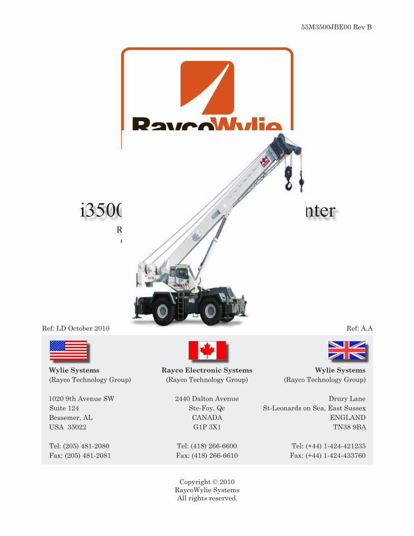
Instruction Manual i3500 Crane information center Rated Capacity Indicator System for Telescopic Cranes Pressure Sensing, Multi-Point Version Copyright © 2010 RaycoWylie Systems All rights reserved. Ref: LD October 2010 Ref: A.A Wylie Systems (Rayco Technology Group) 1020 9th Avenue SW Suite 124 Bessemer, AL USA 35022 Tel: (205) 481-2080 Fax: (205) 481-2081 Rayco Electronic Systems (Rayco Technology Group) 2440 Dalton Avenue Ste-Foy, Qc CANADA G1P 3X1 Tel: (418) 266-6600 Fax: (418) 266-6610 Wylie Systems (Rayco Technology Group) Drury Lane St-Leonards on Sea, East Sussex ENGLAND TN38 9BA Tel: (+44) 1-424-421235 Fax: (+44) 1-424-433760 55M3500JBE00 Rev B
Transcript of i3500 Crane information center - RW SALES & · PDF fileof the crane manufacturer’s...
Instruction Manual
i3500 Crane information centerRated Capacity Indicator System for Telescopic Cranes Pressure Sensing, Multi-Point Version
Copyright © 2010RaycoWylie SystemsAll rights reserved.
Ref: LD October 2010 Ref: A.A
Wylie Systems(Rayco Technology Group)
1020 9th Avenue SWSuite 124Bessemer, ALUSA 35022
Tel: (205) 481-2080Fax: (205) 481-2081
Rayco Electronic Systems(Rayco Technology Group)
2440 Dalton AvenueSte-Foy, QcCANADAG1P 3X1
Tel: (418) 266-6600Fax: (418) 266-6610
Wylie Systems(Rayco Technology Group)
Drury LaneSt-Leonards on Sea, East Sussex
ENGLANDTN38 9BA
Tel: (+44) 1-424-421235Fax: (+44) 1-424-433760
55M3500JBE00 Rev B

This page has been intentionally left blank

This page has been intentionally left blank

i3500 Introduction
4Telescopic Cranes Pressure Sensing Instruction Manual
EC Declaration of Conformity
Product type:
Authorised Representative:
Is in conformity with:
i3500 Rated Capacity Indicator
Wylie SystemsDrury LaneSt Leonards-on-seaEast Sussex , United KingdomTN38 9BA
The provisions of the Machinery Directive (Directive 2006/42/EC)The provisions of the Electromagnetic compatibility Directive (Directive 2004/108/EC)
This conformity is supposed referring to the following standards, documents and requirements:
EN 13000 Cranes – Mobile Cranes EN 12077-2 Cranes Safety, limiting and indicating devicesEN 954-1 Safety and related parts of control systems.
Category 2 EN 60204-32 Safety of machinery. Electrical equipment of machine
Requirement for hoisting machineEN 61000-6-2 Electromagnetic compatibility - immunity EN 61000-6-4 Electromagnetic compatibility - emission
For and on behalf of Wylie Systems, a division of RaycoWylie Systems:
………………………………………………Luc PatryRaycoWylie Quality & Certification ManagerDecember 23, 2009
This document is also the certificate of origin. The product is manufactured in more than one country and all European Union import duties and taxes have been paid in the United Kingdom.
www.raycowylie.com
Rayco Wylie Systems
ISO9001:2008 FM 33972
Manufacturer :Rayco Electronic Systems2440 Av DaltonQuébec, PQ, CanadaG1P 3X1
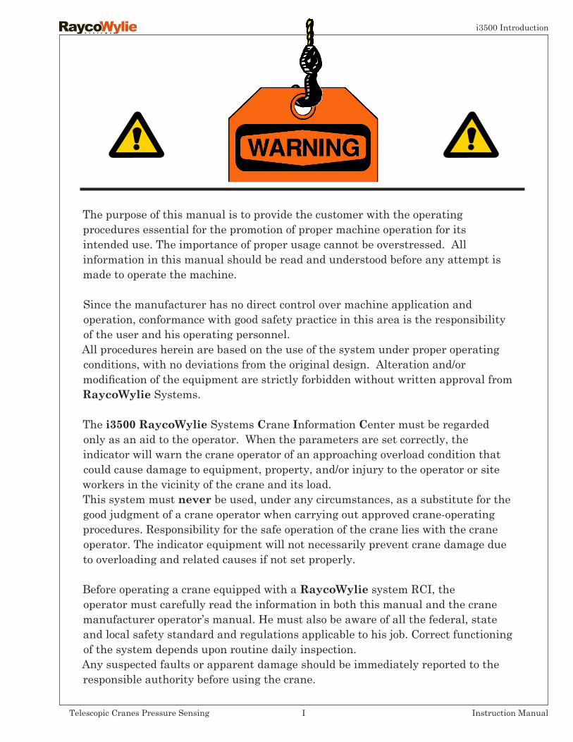
The purpose of this manual is to provide the customer with the operating procedures essential for the promotion of proper machine operation for its intended use. The importance of proper usage cannot be overstressed. All information in this manual should be read and understood before any attempt is made to operate the machine.
Since the manufacturer has no direct control over machine application and operation, conformance with good safety practice in this area is the responsibility of the user and his operating personnel.All procedures herein are based on the use of the system under proper operating conditions, with no deviations from the original design. Alteration and/or modification of the equipment are strictly forbidden without written approval from RaycoWylie Systems.
The i3500 RaycoWylie Systems Crane Information Center must be regarded only as an aid to the operator. When the parameters are set correctly, the indicator will warn the crane operator of an approaching overload condition that could cause damage to equipment, property, and/or injury to the operator or site workers in the vicinity of the crane and its load.This system must never be used, under any circumstances, as a substitute for the good judgment of a crane operator when carrying out approved crane-operating procedures. Responsibility for the safe operation of the crane lies with the crane operator. The indicator equipment will not necessarily prevent crane damage due to overloading and related causes if not set properly.
Before operating a crane equipped with a RaycoWylie system RCI, the operator must carefully read the information in both this manual and the crane manufacturer operator’s manual. He must also be aware of all the federal, state and local safety standard and regulations applicable to his job. Correct functioning of the system depends upon routine daily inspection.Any suspected faults or apparent damage should be immediately reported to the responsible authority before using the crane.
i3500 Introduction
ITelescopic Cranes Pressure Sensing Instruction Manual
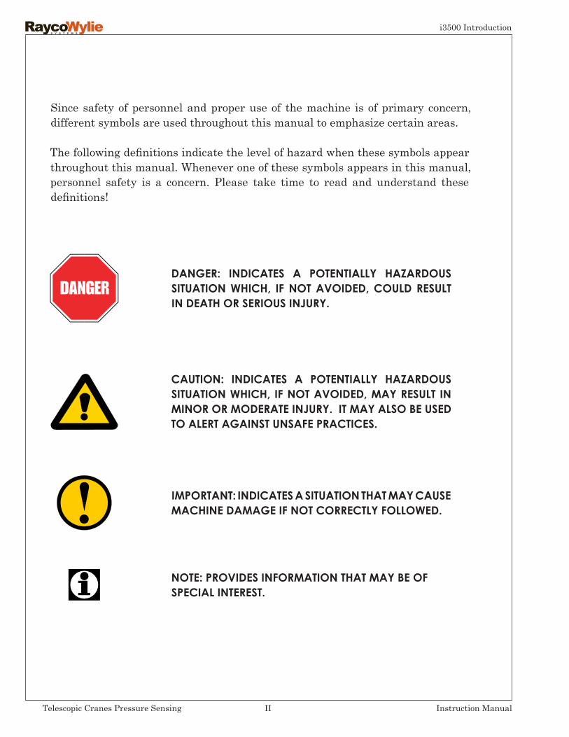
Since safety of personnel and proper use of the machine is of primary concern, different symbols are used throughout this manual to emphasize certain areas.
The following definitions indicate the level of hazard when these symbols appear throughout this manual. Whenever one of these symbols appears in this manual, personnel safety is a concern. Please take time to read and understand these definitions!
NOTE: PROVIDES INFORMATION THAT MAY BE OF SPECIAL INTEREST.
DANGER: INDICATES A POTENTIALLY HAZARDOUS SITUATION WHICH, IF NOT AVOIDED, COULD RESULT IN DEATH OR SERIOUS INJURY.
CAUTION: INDICATES A POTENTIALLY HAZARDOUS SITUATION WHICH, IF NOT AVOIDED, MAY RESULT IN MINOR OR MODERATE INJURY. IT MAY ALSO BE USED TO ALERT AGAINST UNSAFE PRACTICES.
IMPORTANT: INDICATES A SITUATION THAT MAY CAUSE MACHINE DAMAGE IF NOT CORRECTLY FOLLOWED.
i3500 Introduction
IITelescopic Cranes Pressure Sensing Instruction Manual

TABLE OF CONTENTS
EC Declaration of conformityWarnings
1- GENERAL DESCRIPTION OF THE SYSTEM 1.1 Introduction page 4 1.2 Personnelqualification page4 1.3 Intented use of the I3500 System page 4 1.4 Brief description of the I3500 System page 5 1.5 Typical Components Location & Description page 9 1.6 Block Diagram page 10 1.7 Technical Data page 11 2- DETAILED DESCRIPTION OF THE DISPLAY UNIT 2.1 Normal Mode Display (default screen) page 12 2.2 Display Buttons Location and Purpose page 13 2.3 Warning Lights and Indicators Location page 15 2.4 Warning Lights and Indicators Detailed Description page 16
3- INSTALLATION & CALIBRATION 4- OPERATING INSTRUCTIONS 4.1 Safety Instructions page 19 4.2 Residual Risks page 20 4.3 Power On page 21 4.3 Systemconfiguration page21 4.4.1- Duty Number Selection page 22 4.4.2- Hoist Selection page 24 4.4.3- Parts of Line Selection page 25 4.4.4- System Test page 27 4.4.5-SystemConfigurationInformationScreen page28 4.4.6- System Setup page 29
i3500 Introduction
1Telescopic Cranes Pressure Sensing Instruction Manual
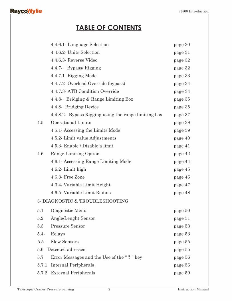
TABLE OF CONTENTS
4.4.6.1- Language Selection page 30 4.4.6.2- Units Selection page 31 4.4.6.3- Reverse Video page 32 4.4.7- Bypass/ Rigging page 32 4.4.7.1- Rigging Mode page 33 4.4.7.2- Overload Override (bypass) page 34 4.4.7.3- ATB Condition Override page 34 4.4.8- Bridging & Range Limiting Box page 35 4.4.8- Bridging Device page 35 4.4.8.2- Bypass Rigging using the range limiting box page 37 4.5 Operational Limits page 38 4.5.1- Accessing the Limits Mode page 39 4.5.2- Limit value Adjustments page 40 4.5.3- Enable / Disable a limit page 41 4.6 Range Limiting Option page 42 4.6.1- Accessing Range Limiting Mode page 44 4.6.2- Limit high page 45 4.6.3- Free Zone page 46 4.6.4- Variable Limit Height page 47 4.6.5- Variable Limit Radius page 48
5- DIAGNOSTIC & TROUBLESHOOTING
5.1 Diagnostic Menu page 50 5.2 Angle/Lenght Sensor page 51 5.3 Pressure Sensor page 53 5.4- Relays page 53 5.5 Slew Sensors page 55 5.6 Detected adresses page 55 5.7 Error Messages and the Use of the ‘‘ ? ’’ key page 56 5.7.1 Internal Peripherals page 56 5.7.2 External Peripherals page 59
i3500 Introduction
2Telescopic Cranes Pressure Sensing Instruction Manual

6- INSPECTION TESTING & MAINTENANCE
6.1- Frequent Inspections page 63 6.2- Periodical Inspections page 63 6.3- Rated Load test page 64 6.4- Maintenance page 65 6.5- Maintenance Procedure page 66 6.6- Adjustements & Repairs page 67
i3500 Introduction
3Telescopic Cranes Pressure Sensing Instruction Manual

-1-
General Description of the System
This manual contains Operation, Troubleshooting and Maintenance information for the i3500 system. When using i3500 system, always observe the safety rules and regulations applicable in the country of operation to reduce the risk of personal injury or damage to the equipment. Each safety instruction throughout this manual must be taken into consideration when using the i3500 system. The information contained in this manual will enable qualified personnel to properly operate and efficiently perform maintenance.
1.2 Personnelqualification
1.3 Intended use
The i3500 system shall be operated only by personnel without limitations in the physical abilities of the upper limbs and no visual or hearing impairment, who have completed all operator trainee qualification requirements and have read and fully understood the instructions in this manual. Operator requirements shall include: demonstrating the ability to read, write and comprehend and use arithmetics and read and understand the load / capacity charts in the language of the crane manufacturer’s operating instruction materials. Maintenance of the system is intended only for fully qualified and trained personnel for this task.
The i3500 system is intended to provide a valuable aid to the crane operator by indicating all relevant parameters typically shown on the duty chart of the crane. The i3500 system shall prevent the crane from supporting a load outside the limits of the permitted radii and outside the loads shown and described on the rated capacity chart or the permissible working load of the ropes when set and operated correctly.
1.1 Introduction
i3500 Introduction
4Telescopic Cranes Pressure Sensing Instruction Manual

i3500 Introduction
5Telescopic Cranes Pressure Sensing Instruction Manual
The i3500 is a computerized crane monitoring system, designed as an operator aid. It comprises sensors fitted to the crane and a display located in the cabin of the crane. This version measures the boom cylinder pressure, the boom angle and length, and it indicates safe or critical conditions, while performing an authorized lift of loads. Optional sensors may also be fitted to monitor the slew angle and the rotation of the hoist drum to provide some extra information to the operator.All the sensors are linked through a single CANbus (Controlled Area Network). The pressure sensors provide electrical signals that are proportional to the actual pressures in the hydraulic boom cylinder system of the crane. An inclinometer provides a signal that is proportional to the boom angle and a reeling drum provides a signal that is proportional to the boom extension. The radius and the load are calculated from these signals with the dimensional crane data preprogrammed in the i3500 system.During operation the load lifted by the crane is calculated from the measured boom cylinder pressure and is automatically compared with corresponding data related to the maximum permissible crane loading.The actual load is expressed as a percentage of the permitted load (% SWL). If this percentage exceeds a preset value, alarms and safety functions are activated. The values of the hook load, the permissible load, the main boom angle and the radius are displayed in a digital form on a graphic liquid crystal display (LCD).If the additional sensors are fitted, then some information about the current slew angle and the hook height will also be available. The required crane duty charts are stored in a non-volatile memory and canonlybemodifiedwiththe approval of the crane manufacturer. The calculated crane parameters and calibration data are stored in an additional non-volatile memory. The calibration of the system is performed only with the use of known loads, boom angles, and other pre-determined data.
Audible alarms
An intermittent buzzer located in the i35000 system display warns the crane operator to take specific course of actions at the approach of the rated capacity. The threshold of the approach alarm has been fixed at 95% of the rated capacity. The buzzer will alert in a continuous way when the rated capacity is reached or exceeded (≥ 100%). Personnel in the danger zone are warned by an external buzzer so that they can get out danger when the rated capacity limiter is activated or overridden. (Continues on next page).
1.4 Brief description of the i3500 System

i3500 Introduction
6Telescopic Cranes Pressure Sensing Instruction Manual
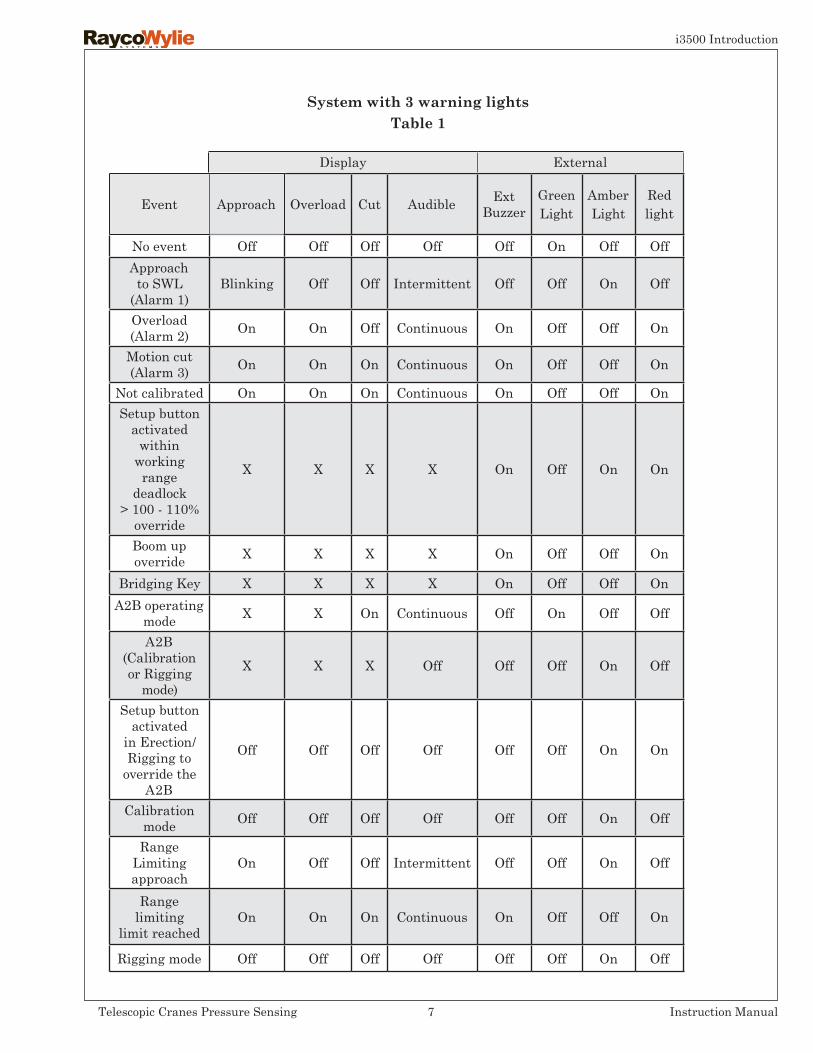
The crane operator will also be warned by the audible alarm when the operational limits or the range limiting function is activated and a selected limit is reached. See Table (1) for more details on audible signal operation.
Visual alarms
The display of the i3500 system has been equipped with up to 3 warning lights to warn the operator and signal for a specific course of action. A yellow light will blink along with the audible alarm at the threshold point of the approach alarm (at 95%) of the rated capacity (100%).
A red light will illuminate when the rated capacity has been reached or exceeded. An additional red light will also turn on when the rated capacity limiter is activated (Cut Off).
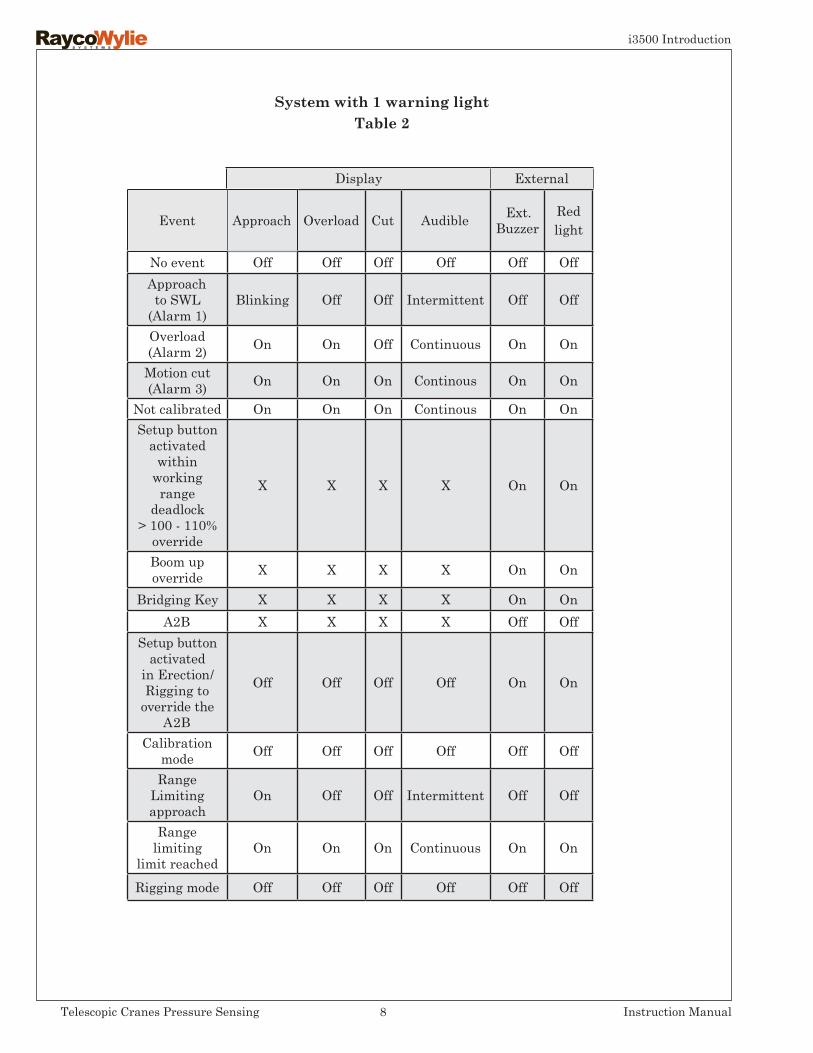
External visual alarms are also provided with the external audible alarm to warn the personnel in the danger zone so that they can be aware of the danger when the rated capacity limiter is activated or overridden. Note that depending on system configuration, your system may be equipped with one or with three external lights. See tables 1 and 2 for external visual alarm operation.
When wearing ear protection safety devices or if using music earphones during crane operations, make sure that they will not impair your ability to hear the audible warning signals while operating the i3500 system.
i3500 Introduction
7Telescopic Cranes Pressure Sensing Instruction Manual
Event Approach Overload Cut Audible ExtBuzzer
GreenLight
AmberLight
Red light
No event Off Off Off Off Off On Off OffApproachto SWL
(Alarm 1)Blinking Off Off Intermittent Off Off On Off
Overload(Alarm 2) On On Off Continuous On Off Off On
Motion cut(Alarm 3) On On On Continuous On Off Off On
Not calibrated On On On Continuous On Off Off OnSetup button
activated within
working range
deadlock> 100 - 110%
override
X X X X On Off On On
Boom upoverride X X X X On Off Off On
Bridging Key X X X X On Off Off OnA2B operating
mode X X On Continuous Off On Off Off
A2B (Calibration or Rigging
mode)X X X Off Off Off On Off
Setup buttonactivated
in Erection/Rigging to
override the A2B
Off Off Off Off Off Off On On
Calibration mode Off Off Off Off Off Off On Off
Range Limiting approach
On Off Off Intermittent Off Off On Off
Range limiting
limit reachedOn On On Continuous On Off Off On
Rigging mode Off Off Off Off Off Off On Off
Display External
Systemwith3warninglightsTable 1
i3500 Introduction
8Telescopic Cranes Pressure Sensing Instruction Manual
Event Approach Overload Cut Audible Ext.Buzzer
Red light
No event Off Off Off Off Off OffApproachto SWL
(Alarm 1)Blinking Off Off Intermittent Off Off
Overload(Alarm 2) On On Off Continuous On On
Motion cut(Alarm 3) On On On Continous On On
Not calibrated On On On Continous On OnSetup button
activated within
working range
deadlock> 100 - 110%
override
X X X X On On
Boom upoverride X X X X On On
Bridging Key X X X X On OnA2B X X X X Off Off
Setup buttonactivated
in Erection/Rigging to
override the A2B
Off Off Off Off On On
Calibration mode Off Off Off Off Off Off
Range Limiting approach
On Off Off Intermittent Off Off
Range limiting
limit reachedOn On On Continuous On On
Rigging mode Off Off Off Off Off Off
Display External
Systemwith1warninglightTable 2
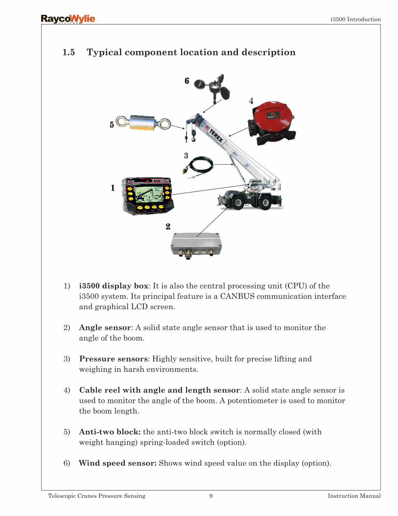
1.5 Typical component location and description
1) i3500 display box: It is also the central processing unit (CPU) of the i3500 system. Its principal feature is a CANBUS communication interface and graphical LCD screen.
2) Angle sensor: A solid state angle sensor that is used to monitor the angle of the boom.
3) Pressure sensors: Highly sensitive, built for precise lifting and weighing in harsh environments.
4) Cablereelwithangleandlengthsensor: A solid state angle sensor is used to monitor the angle of the boom. A potentiometer is used to monitor the boom length.
5) Anti-twoblock:the anti-two block switch is normally closed (with weight hanging) spring-loaded switch (option).
6) Windspeedsensor:Shows wind speed value on the display (option).
i3500 Introduction
9Telescopic Cranes Pressure Sensing Instruction Manual
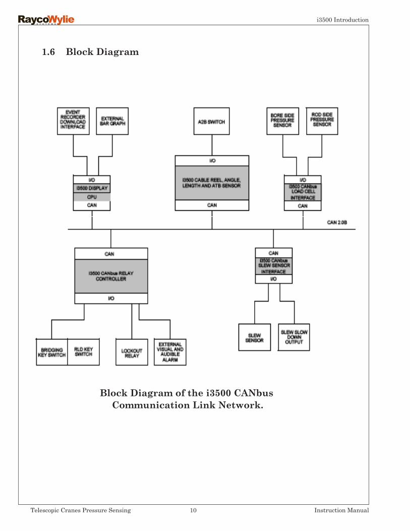
1.6 BlockDiagram
BlockDiagramofthei3500CANbusCommunicationLinkNetwork.
i3500 Introduction
10Telescopic Cranes Pressure Sensing Instruction Manual
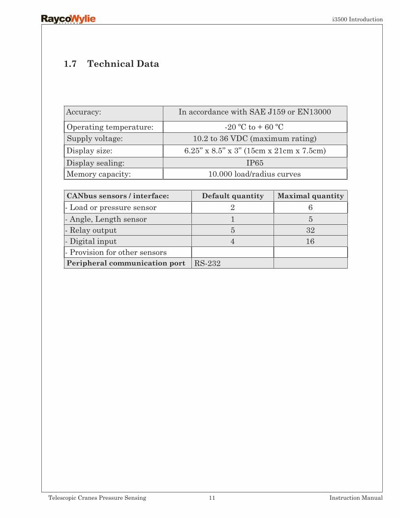
1.7 TechnicalData
Accuracy: In accordance with SAE J159 or EN13000
Operating temperature: -20 ºC to + 60 ºCSupply voltage: 10.2 to 36 VDC (maximum rating)Display size: 6.25’’ x 8.5’’ x 3’’ (15cm x 21cm x 7.5cm)Display sealing: IP65Memory capacity: 10.000 load/radius curves
CANbussensors/interface: Defaultquantity Maximal quantity- Load or pressure sensor 2 6- Angle, Length sensor 1 5- Relay output 5 32- Digital input 4 16- Provision for other sensorsPeripheral communication port RS-232
i3500 Introduction
11Telescopic Cranes Pressure Sensing Instruction Manual
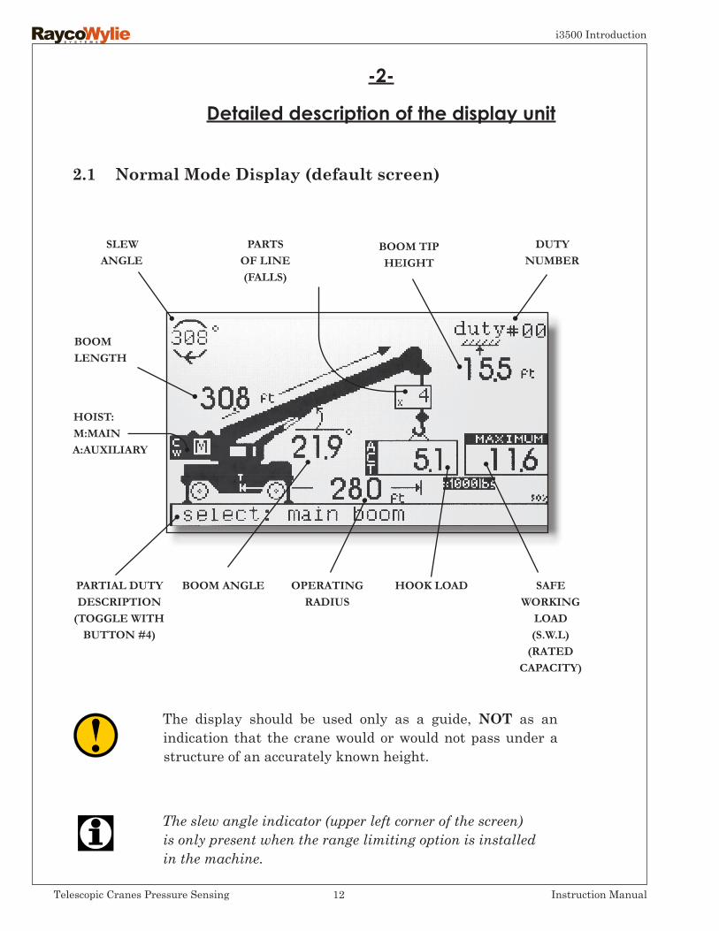
2.1 NormalModeDisplay(defaultscreen)
DUTY NUMBER
SLEW ANGLE
PARTIAL DUTY DESCRIPTION
(TOGGLE WITH BUTTON #4)
HOIST: M:MAIN A:AUXILIARY
PARTS OF LINE (FALLS)
OPERATING RADIUS
BOOMLENGTH
SAFEWORKING
LOAD (S.W.L)
(RATED CAPACITY)
HOOK LOAD
BOOM TIP HEIGHT
BOOM ANGLE
-2-
Detailed description of the display unit
The display should be used only as a guide, NOT as an indication that the crane would or would not pass under a structure of an accurately known height.
The slew angle indicator (upper left corner of the screen)is only present when the range limiting option is installedin the machine.
i3500 Introduction
12Telescopic Cranes Pressure Sensing Instruction Manual

2.2 DisplayButtonsLocationandPurpose
i3500 DISPLAY BOX OVERVIEW
OPERATINGBUTTONS
INTERNALBUZER
GRAPHICALDISPLAY
WARNINGLIGHTS
OPERATING BUTTONS PRESENTATION
MODEBUTTONShows system’s modes. Press this button to chooseone of these operating modes:-Normal mode-System Set Up mode-Diagnostic mode-Calibration mode (password protected).
HOIST/SCROLLUPBUTTONShows hoist menu for selection of the hoist currently in use. Also used to scroll up through options or to increase adjustable values.
PARTS/SCROLLDOWNBUTTONShows parts of line (falls) menu for selection of the number of parts currently in use. Also used to scroll down through options or to decrease adjustable values.
i3500 Introduction
13Telescopic Cranes Pressure Sensing Instruction Manual
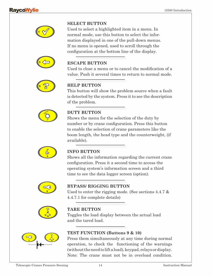
HELPBUTTONThis button will show the problem source when a fault is detected by the system. Press it to see the description of the problem.
DUTYBUTTONShows the menu for the selection of the duty by number or by crane configuration. Press this button to enable the selection of crane parameters like the boom length, the head type and the counterweight, (if available).
INFOBUTTONShows all the information regarding the current crane configuration. Press it a second time to access the operating system’s information screen and a third time to see the data logger screen (option).
BYPASS/RIGGINGBUTTONUsed to enter the rigging mode. (See sections 4.4.7 & 4.4.7.1 for complete details)
TAREBUTTONToggles the load display between the actual loadand the tared load.
SELECTBUTTONUsed to select a highlighted item in a menu. In normal mode, use this button to select the infor-mation displayed in one of the pull-down menus. If no menu is opened, used to scroll through the configuration at the bottom line of the display.
ESCAPEBUTTONUsed to close a menu or to cancel the modification of a value. Push it several times to return to normal mode.
TESTFUNCTION(Buttons9&10)Press them simultaneously at any time during normal operation, to check the functioning of the warnings (without the need to lift a load), keypad, relays or display. Note: The crane must not be in overload condition.
i3500 Introduction
14Telescopic Cranes Pressure Sensing Instruction Manual

2.2 Warning Lights and Indicators Location
PRESET LIMIT(S) REACHED
TWO-BLOCK CONDITION DETECTED
RATED CAPACITY LIMITED BY THE
HOIST ROPE
MOTIONCUT
(RED LIGHT)
OVERLOADWARNING
(RED LIGHT)
APPROACHWARNING(YELLOW LIGHT)
i3500 Introduction
15Telescopic Cranes Pressure Sensing Instruction Manual

2.3 WarningLightsandIndicatorsDetailedDescription
The approach warning light blinks when the load on the hook is between 90% and 99.9% of the rated capacity (adjustable value; EN13000:2010: 90% and 97.5% ). This is accompanied by an audible warning device that is fitted inside the display unit. This light (yellow in color) will also flash on and off if you are approaching within 5 units (feet, meters or degrees) of a predetermined limit (set in the limits setting mode).
The motion cut warning light (red in color) illuminates at or above 100.1% of the rated capacity. This is usually associated with, for example, booming down, telescoping out or hoisting up. The exact operation is specific to the crane model.
The overload warning light (red in color) illuminates at or above 100% of the rated capacity. This light will also turn on if you are reaching a predetermined limit (set in the limits setting mode).
Operate with caution !The crane is working near its maximum operating capacity.
The crane’s maximum capacity has been reached or exceeded.
The crane has exceeded safe operational ratings and is now in an unsafe condition. Hoist up, telescope out and boom down functions will be stopped if a motion cut solenoid is connected to the system.
i3500 Introduction
16Telescopic Cranes Pressure Sensing Instruction Manual
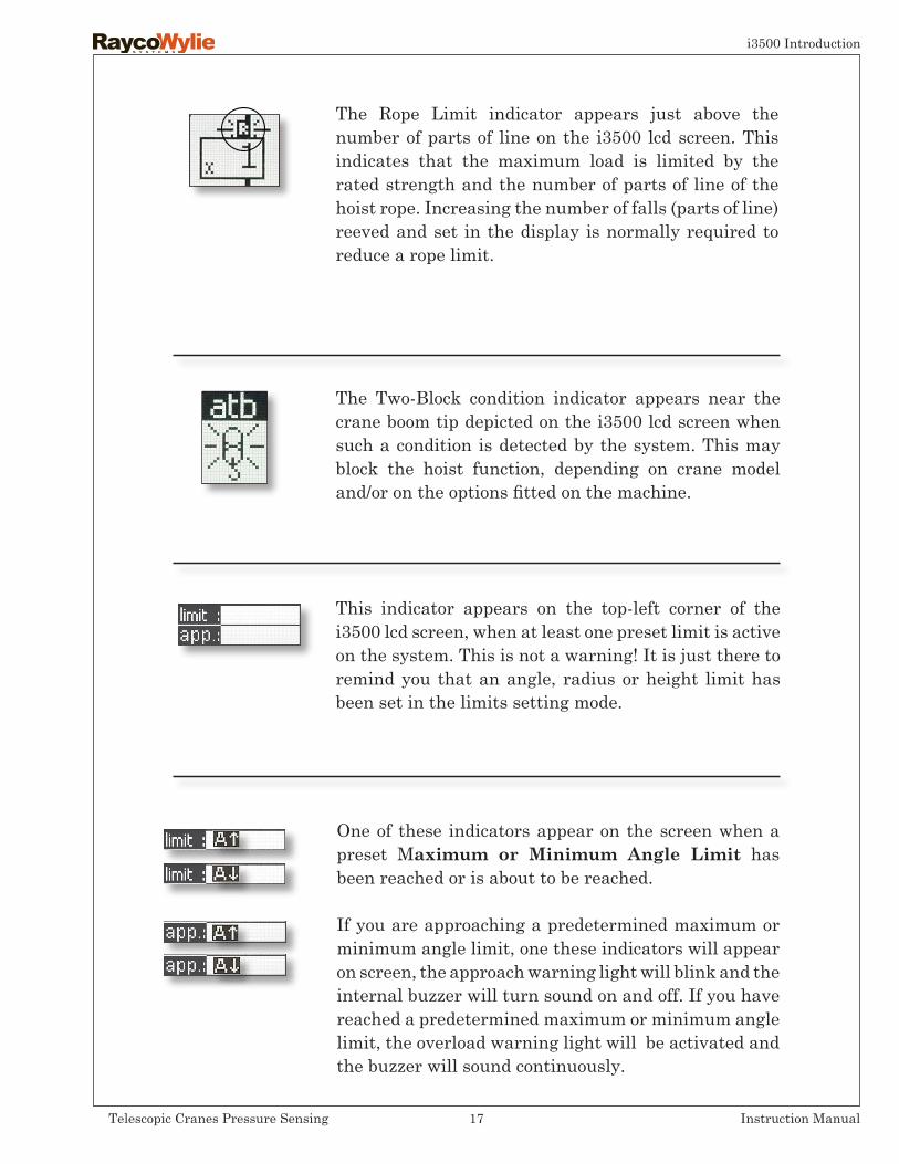
The Two-Block condition indicator appears near the crane boom tip depicted on the i3500 lcd screen when such a condition is detected by the system. This may block the hoist function, depending on crane model and/or on the options fitted on the machine.
This indicator appears on the top-left corner of the i3500 lcd screen, when at least one preset limit is active on the system. This is not a warning! It is just there to remind you that an angle, radius or height limit has been set in the limits setting mode.
The Rope Limit indicator appears just above the number of parts of line on the i3500 lcd screen. This indicates that the maximum load is limited by the rated strength and the number of parts of line of the hoist rope. Increasing the number of falls (parts of line) reeved and set in the display is normally required to reduce a rope limit.
One of these indicators appear on the screen when a preset Maximum or Minimum Angle Limit has been reached or is about to be reached.
If you are approaching a predetermined maximum or minimum angle limit, one these indicators will appear on screen, the approach warning light will blink and the internal buzzer will turn sound on and off. If you have reached a predetermined maximum or minimum angle limit, the overload warning light will be activated and the buzzer will sound continuously.
i3500 Introduction
17Telescopic Cranes Pressure Sensing Instruction Manual

The zones where the system will warn the operator that a Preset Limit is being approached can be changed as required. By default these values are set to: 5 degrees for a min/max angle limit and 2 feet or meters (depending on the units set at calibration) for a height or radius limit.
In some systems, Limits values are not active when electric power is first applied to the i3500 and they are automatically disabled if electric power is removed.
Reaching an operator’s Preset Limit (set in the Limits Setting Mode) will not result in crane motion cut-off.
This indicator appears on the screen when a preset Maximum Radius Limit has been reached or is about to be reached.
If you are approaching a predetermined maximum radius limit, this indicator will appear on the screen, the approach warning light will blink and the internal buzzer will turn sound on and off. If you have reached a predetermined maximum radius limit, the overload warning light will light up and the buzzer will sound continuously.
This indicator appears on the screen when a preset Maximum Height Limit has been reached or is about to be reached.
If you are approaching a predetermined maximum height limit, this indicator will appear on the screen, the approach warning light will blink and the internal buzzer will sound on and off. If you have reached a predetermined maximum height limit, the overload warning light will light up and the buzzer will sound continuously.
i3500 Introduction
18Telescopic Cranes Pressure Sensing Instruction Manual

-3-
Installation & Calibration
Installation of the i3500 system shall be performed by a qualified technician. Furthermore, calibration of the i3500 system must be performed by a RaycoWylie certified technician. The RaycoWylie technician will perform a complete and structured verification of the whole system before beginning the system’s calibration.
Failure to calibrate the system properly can result in overloading of the crane risking machine breakage or tipping that could result in serious injury or death. Always refer to a RaycoWylie certified technician to calibrate your system.
Installation and calibration manuals are available at RaycoWylie upon request. Please note that the installation and calibration instructions have intentionally not been included in this instruction manual.
19Telescopic Cranes Pressure Sensing Instruction Manual
i3500 Operation
-4-
Operating Instructions
4.1 SafetyInstructions:
When operating the i3500 system, always observe the safety rules and regulations applicable in the country of operation to reduce the risk of personal injury or damage to the equipment. Read the following safety instructions before attempting to operate this system.
1. The i3500 Rated Capacity Indicator must be properly set-up according to the crane’s configuration and operating work site situation. Wrong Set-up can cause the i3500 indicator system to show unreliable information which may result in hazardous conditions arising such as an overload.
2. The i3500 system is purely an aid to the operator. Responsibility for the safe operation of the crane lies with the crane operator. The i3500 system will not necessarily prevent crane damage due to overloading and/or other related causes.

20Telescopic Cranes Pressure Sensing Instruction Manual
i3500 Operation
3. Proper functioning of the equipment is dependent upon proper daily inspections and compliance to the operating instructions described in this manual.
4. During normal operation, the rated capacity of a crane should not be
exceeded. Therefore the overload indication should not be used as a normal operating feature.
5. The crane should be operated at all times in such a way that the crane’s motion occurs smoothly and at a safe speed.
6. In order to have the proper rated capacity and radius, the system must be configured properly. Failure to properly configure the system can result in machine breakage or tipping which could lead to serious injury or death.
7. The operator must verify the crane configurations and number of parts of line for each available hoist every time he/she enters the crane and every time the crane is rigged.
Note: each hoist has its own configuration set-up kept in memory and simply by changing the hoist from main to auxiliary the configuration and number of parts of line will change to suit.
4.2 ResidualRisks
In spite of the application of all relevant safety regulations and the imple-mentation of safety devices, certain residual risks cannot be avoided:
• Risks caused by no indication of malfunction of the output relays avoiding cut off motion to operate in overload conditions, causing machine breakage or tipping that could result in injury or death.
Improper configuration of the i3500 system may also cause a ‘‘Zero Capacity’’ if no chart is found to match the configuration set by the operator.
21Telescopic Cranes Pressure Sensing Instruction Manual
i3500 Operation
• The system gives no indication of the presence of power lines in the crane working area, causing the risk of operating the crane in the proximity of power lines that could result in injury or death.
• The system gives no indication whether the outriggers have been fully extended, causing the risk of machine breakage or tipping that could result in injury or death.
• The system gives no indication of the crane level, causing risk of machine breakage or tipping that could result in injury or death.
• System gives no indication of poor ground stability causing risk of machine breakage or tipping that could result in injury or death.
Switch on the electric power (i.e.: crane key switch) to the i3500 system. The indicator will perform a “Self-test” during which time (approx. 10 sec.) the audible alarm will sound, the approach, overload and motion cut lights will illuminate and the display will show the RaycoWylie’s logo. Subsequently, the i3500 system goes into normal operating mode as shown in Section 2.1 “i3500 normal mode display” of this manual. The normal mode screen allows you to visualize the Hook load, Rated capacity, Radius, Boom angle, Hoist used, the Parts of line, etc.
4.3 PowerOn
4.2 ResidualRisks(cont’d)

DutybuttonUsed for duty number selection.
Parts/ScrolldownbuttonUsed for parts of line (falls) selection.
The system configuration is done using the following three key buttons:
Hoist/Scroll up buttonUsed for hoist selection
4.4 SystemConfiguration
4.4.1DutyNumberSelection
Carefully read and understand these instructions before selecting a duty number. Selecting the wrong duty number can result in overloading of the crane risking machine breakage or tipping that could result in serious injury or death. Never select a duty number if you have any doubts, instead seek the advice of a qualified technician. Make sure that the duty number displayed in the normal mode screen matches the current configuration of the machine.
22Telescopic Cranes Pressure Sensing Instruction Manual
i3500 Operation

4.4.1DutyNumberSelection(cont’d)
Press the Duty button (7) to select a unique duty number (code) that includes all the configuration details such as boom/jib, counterweight, outrigger-/crawler/tyres, hoist etc. The duty number sets all of the machine parameters in one setting except the parts of line in use. Refer to the laminated i3500 duty selection table* supplied with your system for more details.* This document is a plasticized sheet of paper and it must be stored in the operator’s cab for duty selection purpose.
In case of need of assistance, contact RaycoWylie with the serial number of your system for technical advice.
The current duty number is displayed in the upper right corner of the normal display and additional configuration information can be seen by pressing Info button (8).
*Change is not permitted with a load suspended*
Duty number menu(b)(a)
Fig 1
23Telescopic Cranes Pressure Sensing Instruction Manual
i3500 Operation
Here you can input a specific duty number in the i3500 system. For example, if you know that the duty number 57 represents your crane rigged with a 100 ft boom length, outriggers extended and with a 40 ft jib at 10°, it would be more convenient to enter the number 57 instead of having to choose each correct parameters individually. Look up the crane duty number to be used on the i3500 duty list. The currently selected duty number is displayed in the upper right corner of the display (see Fig. 1, b).
or
or
1) Press the Dutybutton (7) to display the duty menu Note: the duty number should be already highlighted
2) Press Selectbutton(4) to enter the duty number menu.
3) Press Scroll UporDown button to highlight the desired number for the first digit (see fig.1, a)
4) Push Selectbutton(4) to confirm your choice.
5) Scroll UporDown to highlight the desired number for the second digit.
6) Press Selectbutton(4) to confirm your choice.
7) Repeat steps 5 and 6 for the last two digits.
Changing the crane configuration bythe duty number
4.4.1DutyNumberSelection(cont’d)
The duty number is a four digit entry. Add leading zeros (0) before the desirednumber as necessary. Example: duty#65 = 0065, duty#8 = 0008.
24Telescopic Cranes Pressure Sensing Instruction Manual
i3500 Operation
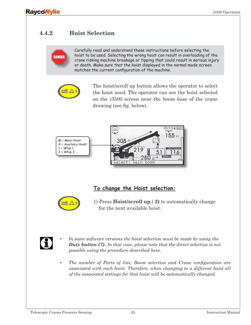
4.4.2 Hoist Selection
The hoist/scroll up button allows the operator to select the hoist used. The operator can see the hoist selected on the i3500 screen near the boom base of the crane drawing (see fig. below).
M = Main HoistA = Auxiliary Hoist1 = Whip 12 = Whip 2
To change the Hoist selection:
1) Press Hoist/scroll up (2) to automatically change for the next available hoist.
Carefully read and understand these instructions before selecting the hoist to be used. Selecting the wrong hoist can result in overloading of the crane risking machine breakage or tipping that could result in serious injury or death. Make sure that the hoist displayed in the normal mode screen matches the current configuration of the machine.
• In some software versions the hoist selection must be made by using the Duty button (7). In that case, please note that the direct selection is not possible using the procedure described here.
• The number of Parts of line, Boom selection and Crane configuration are associated with each hoist. Therefore, when changing to a different hoist all of the associated settings for that hoist will be automatically changed.
25Telescopic Cranes Pressure Sensing Instruction Manual
i3500 Operation

4.4.3 Parts of Line Selection
Parts/Scrolldownbutton(3)This button allows the operator to select the number of parts of line used.
The operator can see the current number of parts selected just above the hook on the on the i3500 screen.
Parts of Line
SelectionMenu
To change the parts of line selection:
1) Press the Parts/Scrolldownbutton (3) to display the parts of line selection menu.
2) Scroll up or down with buttons(2) & (3) to highlight the desired number of parts of line.
3) Push Select button(4)to confirm your choice.
Carefully read and understand these instructions before selecting the Parts of line used. Selecting the wrong Parts of line can result in overloading the rope risking breakage that could result in serious injury or death. Make sure that the Parts of line displayed in the normal mode screen matches the current configuration of the machine.
26Telescopic Cranes Pressure Sensing Instruction Manual
i3500 Operation
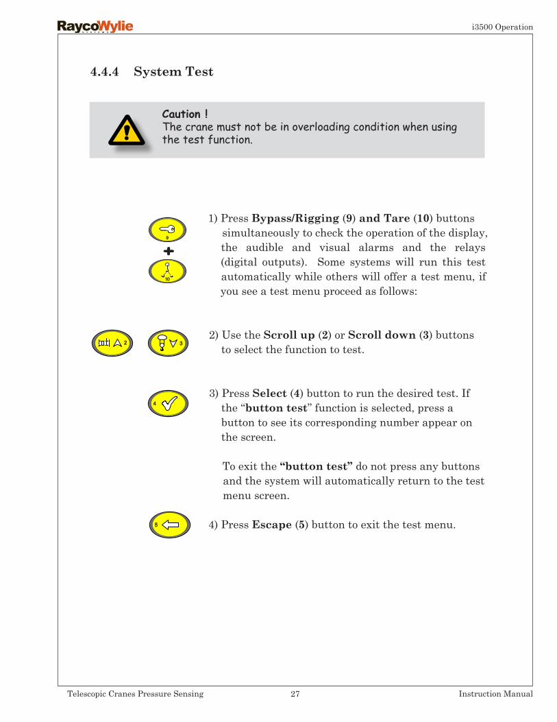
4.4.4 System Test
1) Press Bypass/Rigging (9) and Tare (10) buttonssimultaneously to check the operation of the display, the audible and visual alarms and the relays (digital outputs). Some systems will run this test automatically while others will offer a test menu, if you see a test menu proceed as follows:
2) Use the Scroll up (2) orScrolldown(3) buttons to select the function to test.
3) Press Select (4) button to run the desired test. If the ‘‘button test’’ function is selected, press a button to see its corresponding number appear on the screen.
To exit the ‘‘buttontest’’ do not press any buttons and the system will automatically return to the test menu screen.
4) Press Escape (5) button to exit the test menu.
Caution !The crane must not be in overloading condition when using the test function.
27Telescopic Cranes Pressure Sensing Instruction Manual
i3500 Operation
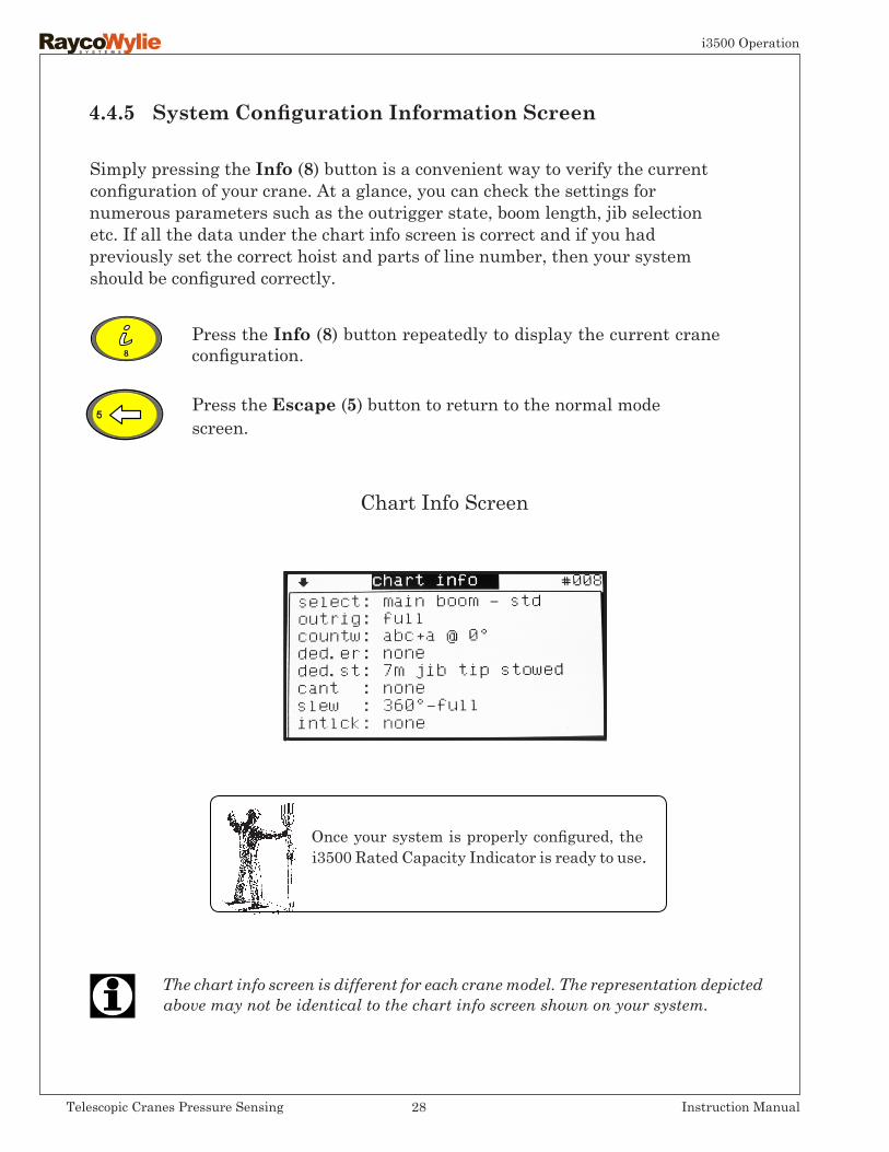
Simply pressing the Info (8) button is a convenient way to verify the current configuration of your crane. At a glance, you can check the settings for numerous parameters such as the outrigger state, boom length, jib selection etc. If all the data under the chart info screen is correct and if you had previously set the correct hoist and parts of line number, then your system should be configured correctly.
Chart Info Screen
Once your system is properly configured, the i3500 Rated Capacity Indicator is ready to use.
4.4.5SystemConfigurationInformationScreen
The chart info screen is different for each crane model. The representation depicted above may not be identical to the chart info screen shown on your system.
Press the Info (8) button repeatedly to display the current crane configuration.
Press the Escape (5) button to return to the normal mode screen.
28Telescopic Cranes Pressure Sensing Instruction Manual
i3500 Operation
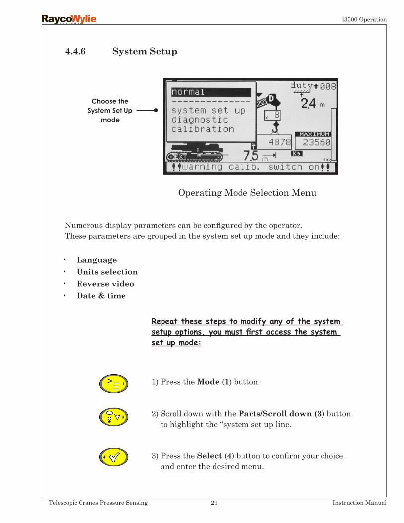
Numerous display parameters can be configured by the operator.These parameters are grouped in the system set up mode and they include:
• Language• Unitsselection• Reverse video• Date&time
4.4.6 System Setup
Repeat these steps to modify any of the system setup options, you must first access the system set up mode:
1) Press the Mode (1) button.
2) Scroll down with the Parts/Scrolldown(3) button to highlight the ‘‘system set up line.
3) Press the Select (4) button to confirm your choice and enter the desired menu.
Operating Mode Selection Menu
Choose theSystem Set Up
mode
29Telescopic Cranes Pressure Sensing Instruction Manual
i3500 Operation

4.4.6.1 Language Selection
All of the i3500’s text messages can be displayed in multiple languages: English (default), as specified in the menu order.
To change the language proceed as follows:
1) Repeat steps 1 to 3 of the preceding section (system setup options section). Select language.
2) The language line should be highlighted on the display by now. If not, scroll up or down with the Hoist/Scroll up (2) or Parts/Scrolldown(3) buttons to highlight the desired language.
3) Press Select (4) button to confirm your choice.
or
30Telescopic Cranes Pressure Sensing Instruction Manual
i3500 Operation
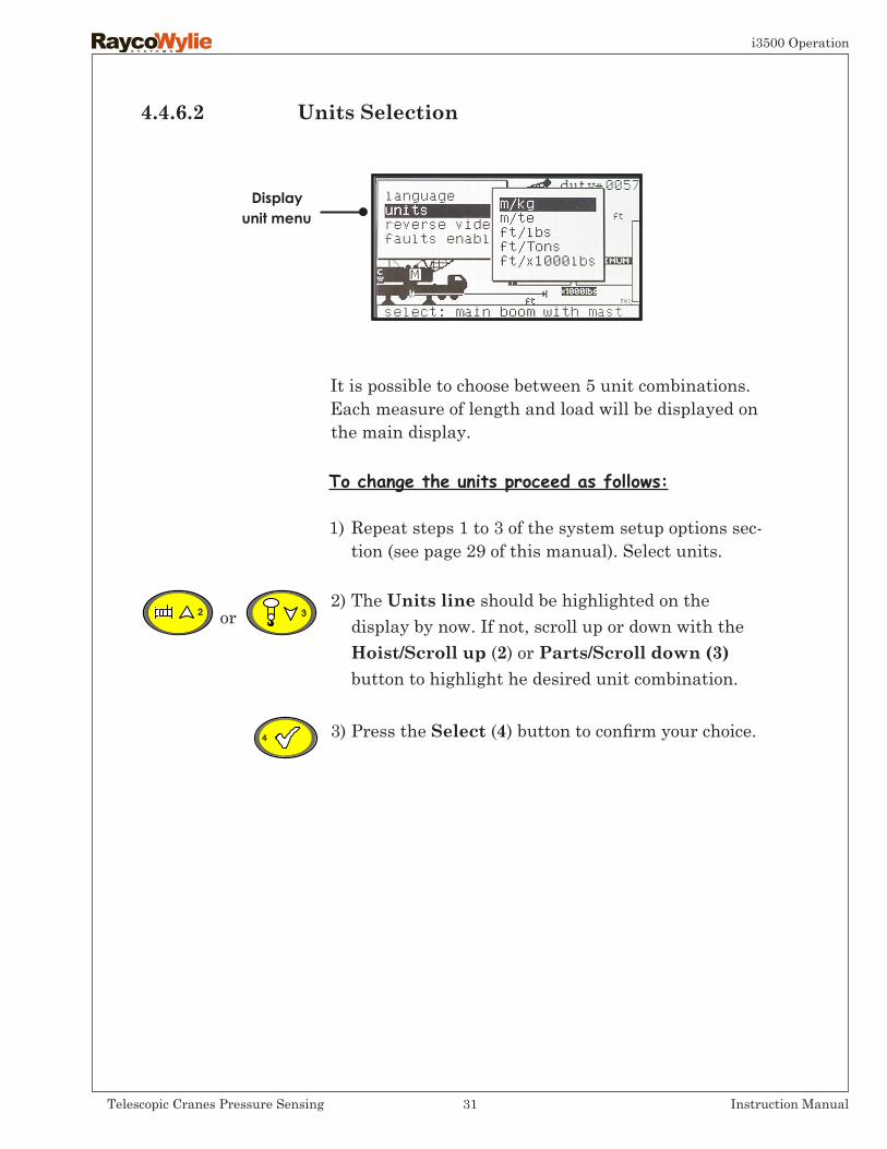
4.4.6.2 UnitsSelection
It is possible to choose between 5 unit combinations.Each measure of length and load will be displayed on the main display.
To change the units proceed as follows:
1) Repeat steps 1 to 3 of the system setup options sec- tion (see page 29 of this manual). Select units.
2) The Unitsline should be highlighted on the display by now. If not, scroll up or down with the Hoist/Scroll up (2) or Parts/Scrolldown(3) button to highlight he desired unit combination.
3) Press the Select (4) button to confirm your choice.
or
Displayunit menu
31Telescopic Cranes Pressure Sensing Instruction Manual
i3500 Operation
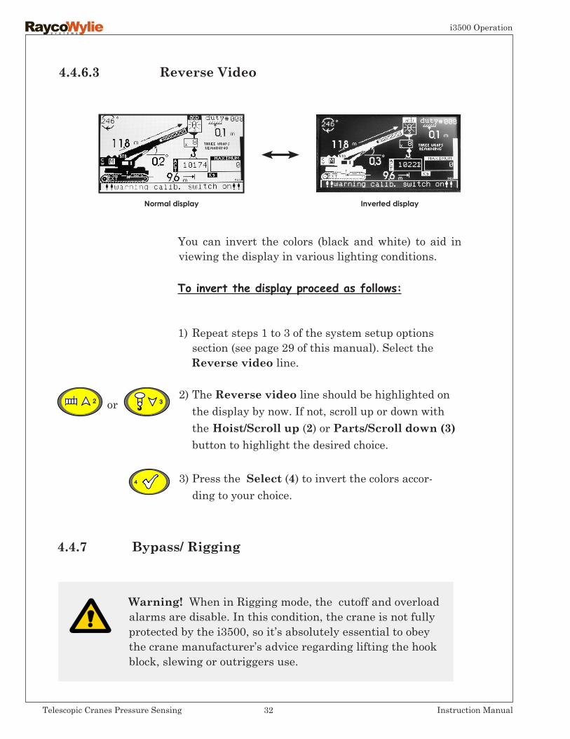
4.4.6.3 Reverse Video
You can invert the colors (black and white) to aid in viewing the display in various lighting conditions.
To invert the display proceed as follows:
1) Repeat steps 1 to 3 of the system setup options section (see page 29 of this manual). Select the Reverse video line.
2) The Reverse video line should be highlighted on the display by now. If not, scroll up or down with the Hoist/Scroll up (2) or Parts/Scrolldown(3) button to highlight the desired choice.
3) Press the Select (4) to invert the colors accor- ding to your choice.
or
Normal display Inverted display
4.4.7 Bypass/ Rigging
Warning! When in Rigging mode, the cutoff and overload alarms are disable. In this condition, the crane is not fully protected by the i3500, so it’s absolutely essential to obey the crane manufacturer’s advice regarding lifting the hook block, slewing or outriggers use.
32Telescopic Cranes Pressure Sensing Instruction Manual
i3500 Operation

4.4.7Bypass/Rigging (cont’d)
4.4.7.1 RiggingMode(Maintenance/ErectionMode)
It is often necessary with many cranes, when stowing or erecting the machine to go outside the working ‘‘envelope’’ for which the crane manufacturer provides ratings. For example, the boom stowed position may be outside the maximum load radius or minimum boom angle specified on any load chart. For this reason, RaycoWylie systems provide a Maintenance/ Erection mode, where the boom may be lowered to or raised from the horizontal position without the external alarm continuously sounding or the motion cut (if fitted) operating.
Itisimportanttonotethefollowingpointswheninriggingmode:
• There are No lock-outs (except for the ATB)• The ATB switch is still monitored.• No audible alarms• The Amber Light is on• The speeds of the movement are not limited. • A flashing rigging message is shown on the display. • The rigging mode can be accessed when the SWL is zero.
The rigging mode isautomaticallyexitedwhen:
• The system is powered off or
• The SWL is greater than zero.
The Bypass/Rigging (9) button will be used to access the following functions: To access the Rigging Mode, to override an Overload Condition and to override an ATB condition. The operator can override the system (lockout) in the event of an emer-gency by pressing the Bypass / Rigging button. The Bypass/Rigging button must be pushed again after 15 seconds.
33Telescopic Cranes Pressure Sensing Instruction Manual
i3500 Operation
4.4.7.2 OverloadOverride(Bypass)
4.4.7.3 ATBConditionOverride(Bypass)
When overriding the lock-outs during an overload condition, the speeds of the movements are limited to 15% (25% on some machines) of the permissible working speed for the corresponding load case. The external alarm and the external amber and red warning lights are activated. Also, the override message flashes on the display.
The overload condition can be overridden when:
• The load is above or equal to 100% SWL and• The load is below 110% SWL and• A valid duty is selected and the capacity is greater than 0; and• There are no faulty sensors.
Theoverrideisautomaticallycancelledwhen:
• The load exceeds 110% SWL or• The load is below 100% SWL or• The bypass button is pressed a second time or• The control levers are in neutral position for more than 10s. or• There is a faulty sensor; or• At engine stop or• An ATB condition occurs or• The RCI/LMI resets.
AnATBconditioncanbeoverriddenwhen:
• The system is in rigging mode and• There is an ATB condition (A2B)
• TheATBoverrideisautomaticallycancelledwhen:
• - The bypass button is released; or• - The ATB condition is cleared; or• - The Rigging mode is exited.
34Telescopic Cranes Pressure Sensing Instruction Manual
i3500 Operation
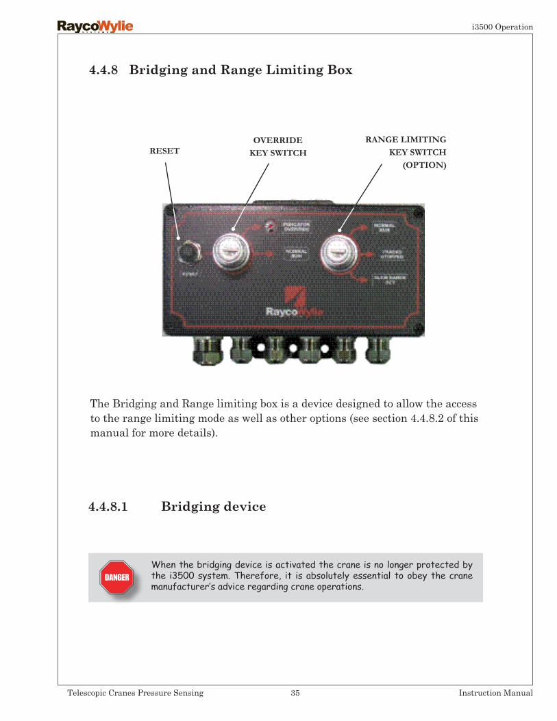
The Bridging and Range limiting box is a device designed to allow the access to the range limiting mode as well as other options (see section 4.4.8.2 of this manual for more details).
4.4.8 Bridging and Range Limiting Box
4.4.8.1 Bridging device
When the bridging device is activated the crane is no longer protected by the i3500 system. Therefore, it is absolutely essential to obey the crane manufacturer’s advice regarding crane operations.
35Telescopic Cranes Pressure Sensing Instruction Manual
i3500 Operation
RANGE LIMITINGKEY SWITCH
(OPTION)RESET
OVERRIDEKEY SWITCH

A bridging device is an embedded electronic mechanism designed to be used in case of system component failure or in case of emergency. This safety feature can be accessed through a two-position momentary key switch. A Reset Button and a Status Led are also provided. (See fig. on section 4.4.8 on page 35). A bridging device may be provided if it’s located outside of the crane operator’s cab and it’s under lock and key and it resets automatically at engine stop not later than 30 min.
Upon activation of the bridging device, the speed of all movements increasing the loading condition is fixed at 15% max (25% in some machines) of the permissible working speed for the corresponding load case.
Furthermore, when the bridging device is enabled, the external alarm and the external warning red light are activated. An override message flashes on the system display.
Thebridgingisactivatedwhen:
• The momentary switch is turned to the “Indicator override” position.
Thebridgingiscancelledwhen:
• The reset button is pressed or• The engine stops or• The bridging is active for more than 30 min.
4.4.8.1 Bridgingdevice(cont’d)
36Telescopic Cranes Pressure Sensing Instruction Manual
i3500 Operation
4.4.8.2 Bypass / Rigging operation (UsingtheBridgingandRangelimitingbox)
(Refertosection4.4.8ofthismanual)
Resetbutton:Press and release the Reset button to cancel the override.
OverrideKeySwitch
Generaloverride:Turn the override key switch to the ‘‘Indicator override’’ position and release for a complete override. The override indicator will be activated.
RangeLimitingKeySwitch
NormalRunposition:Normal mode. The system works without a programmed limit.
SlewRangeSetposition:
This switch position allows access to the Range-limiting mode (refer to section 4.6 of this manual).
Tracksstoppedposition: This switch position locks the machine tracks in place to stop it from moving when one or several limits have been pro-grammed in the system.
This added safety feature is available in option.
37Telescopic Cranes Pressure Sensing Instruction Manual
i3500 Operation
4.5 Operational Limits Setting
In the Operational Limits Setting Mode, the operator can set and activate/deactivate four (4) operational limits in addition to those automatically provided by the i3500 RCI system. These are as follows:
1) The Minimum Boom Angle Limit.2) The Maximum Boom Angle limit.3) The Maximum Boom Tip Height Limit.4) The Maximum Operating Radius Limit.
Carefully read and understand these instructions before setting the Operational Limits. Setting the wrong Operational Limits can result in accidentally running into obstacles which could lead to serious injury or death.
Important:PleasenotethatifyourmachineisequippedwiththeRangelimitingkeyswitchoption,theOperationalLimitssettingmodewillNotbeavailableforselection(refertosection4.4.8ofthismanualformoredetails).
38Telescopic Cranes Pressure Sensing Instruction Manual
i3500 Operation

4.5.1 Accessing the Operational Limits Setting Mode
1) Press the Mode button (1) to display the mode selection menu.
2) Press Parts/Scrolldown (3) button once to highlight the limits setting mode.
3) Press Select (4)button to enter the limits setting menu.
Limits setting Menu
Please note that limits are not active* when power is first applied to the i3500 system and they are automatically disabled if power is removed.
* Depending on software version, in some systems the limits will be kept active even if power is cut.
39Telescopic Cranes Pressure Sensing Instruction Manual
i3500 Operation

4.5.2 Limit Value Adjustment
1) Access the Operational limiting mode (refer to section 4.5.1 for more details).
2) Use the Hoist/Scroll up (2) and Parts/Scroll down(3) buttons to highlight the limit you want to edit.
3) Press Select (4) button to confirm your choice.
4) Press the Hoist/Scroll up (2) and Down (3) button to select the desired value for this particular limit.
5) Press Select (4) button to confirm the selected value.
6) Press Escape(5) button to return to the normal operating mode.
or
or
40Telescopic Cranes Pressure Sensing Instruction Manual
i3500 Operation
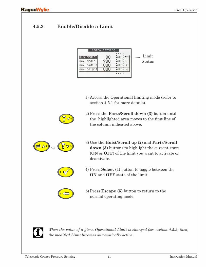
4.5.3 Enable/DisableaLimit
When the value of a given Operational Limit is changed (see section 4.5.2) then, the modified Limit becomes automatically active.
1) Access the Operational limiting mode (refer to section 4.5.1 for more details).
2) Press the Parts/Scrolldown(3) button until the highlighted area moves to the first line of the column indicated above.
3) Use the Hoist/Scroll up (2) and Parts/Scroll down(3)buttons to highlight the current state (ON or OFF) of the limit you want to activate or deactivate.
4) Press Select (4) button to toggle between the ON and OFF state of the limit.
5) Press Escape(5) button to return to the normal operating mode.
or
LimitStatus
41Telescopic Cranes Pressure Sensing Instruction Manual
i3500 Operation
4.6 Range Limiting Option
Carefully read and understand these instructions before setting the Operational Range Limits. Setting the wrong Operational Range Limits can result in accidentally running into obstacles which could lead to serious injury or death.
The Operational Range Limits settings must be reprogrammed everytime the crane is moved.
RaycoWylie recognizes that operating cranes in proximity to power lines or equipment is an extremely hazardous practice that requires extra precautions. It is therefore essential to operate the crane outside the minimum clearances allowed in such a way that there is no possibility of the crane, load line or load becoming a conductive path, to avoid the risk of being electrocuted. The crane shall not be used to handle material stored under electrical power lines unless any combination of boom, load, load line, or machine cannot enter the prohibited zone. The range limiting option provided by the i3500 system shall not be used to delimit the prohibited zone. Refer to federal, state, local safety standards and regulations applicable in your country regarding operating cranes in proximity to power lines.
Crane travel is prohibited when Range Limiting is activated.
42Telescopic Cranes Pressure Sensing Instruction Manual
i3500 Operation

4.6 RangeLimitingOption(cont’d)
RANGE LIMITING WARNINGS:
CUT-OFF CONDITION
LIMIT REACHED
APPROACH WARNING OF THE LIMIT
Shows which zone is programmed:limit high (roof)variable limit heightvariable limit radiusfree zone (two walls)
Shows which limit is reached:
RADIUS
HEIGHT
WALL
Menuoptions:
When the system is equipped with the Range Limiting key switch option, the system automatically selects the Range Limiting mode as the only possible choice. In that case, the following menu options* are offered:
• High Limit• Free Zone• Variable Limit Height• Variable Limit Radius
* In most systems, only one menu option can be chosen at the time; however, this may vary depending on software version.
43Telescopic Cranes Pressure Sensing Instruction Manual
i3500 Operation
4.6.1 Accessing Range Limiting Mode
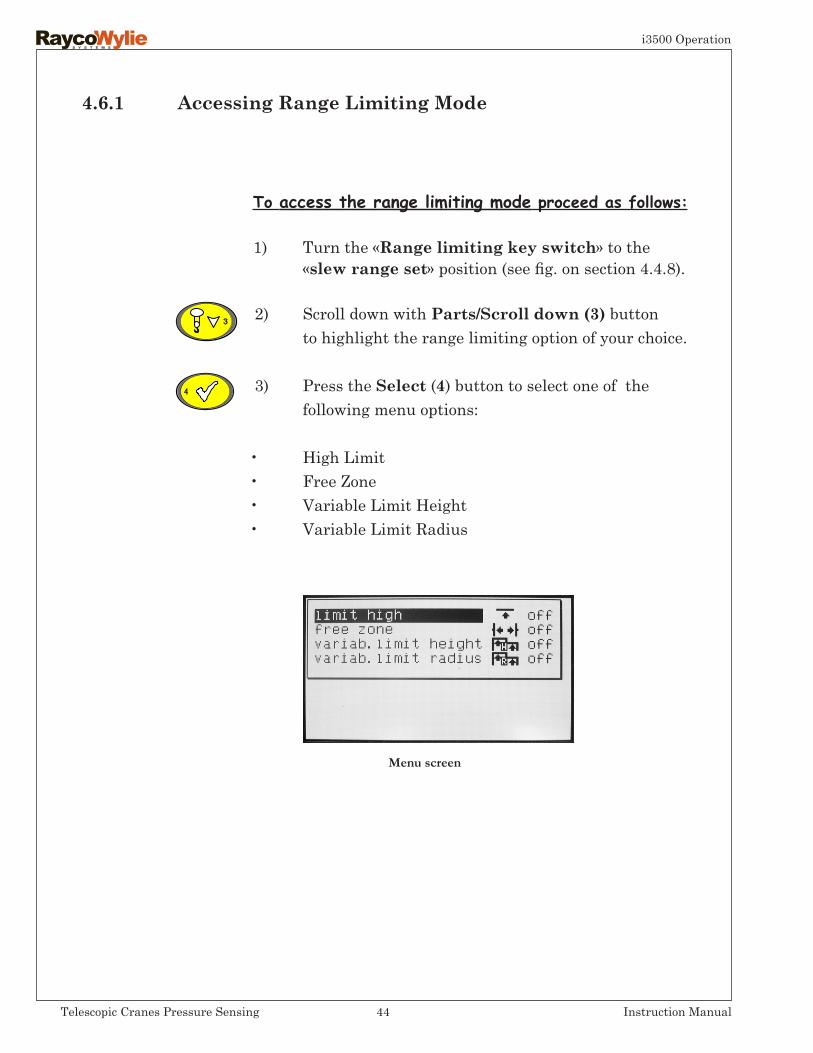
To access the range limiting mode proceed as follows:
1) Turn the «Rangelimitingkeyswitch» to the «slewrangeset» position (see fig. on section 4.4.8).
2) Scroll down with Parts/Scrolldown(3) button to highlight the range limiting option of your choice.
3) Press the Select (4) button to select one of the following menu options:
• High Limit• Free Zone• Variable Limit Height• Variable Limit Radius
Menu screen
44Telescopic Cranes Pressure Sensing Instruction Manual
i3500 Operation
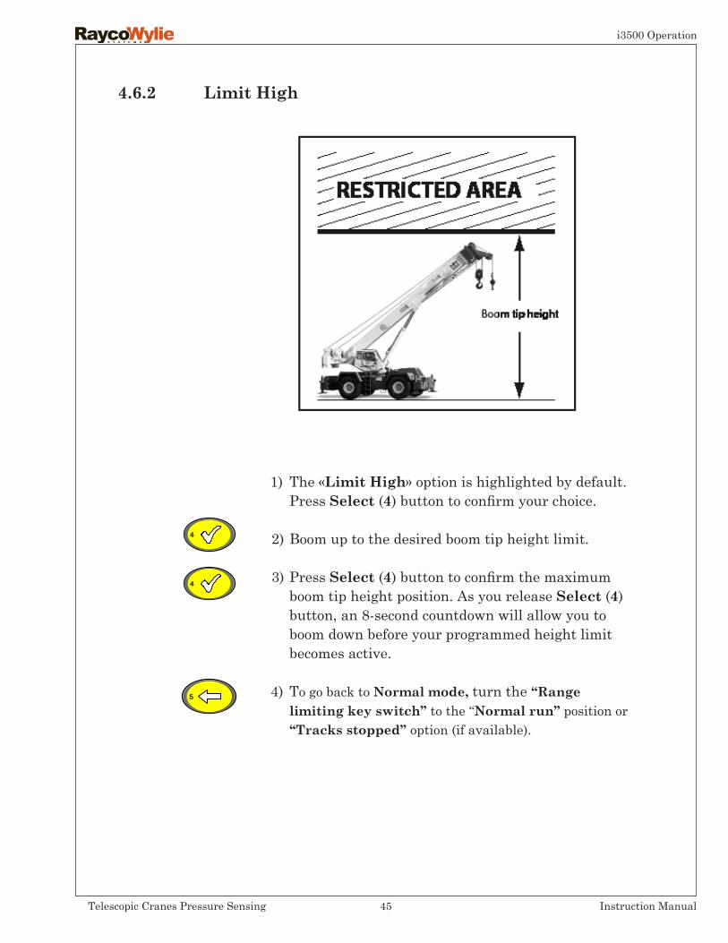
4.6.2 Limit High
1) The «Limit High» option is highlighted by default. Press Select (4) button to confirm your choice.
2) Boom up to the desired boom tip height limit.
3) Press Select (4) button to confirm the maximum boom tip height position. As you release Select (4) button, an 8-second countdown will allow you to boom down before your programmed height limit becomes active.
4) To go back to Normal mode, turn the ‘‘Range limitingkeyswitch’’to the ‘‘Normalrun’’ position or ‘‘Tracksstopped’’option (if available).
45Telescopic Cranes Pressure Sensing Instruction Manual
i3500 Operation

VIEW FROM TOP
First wall
Second wall
4.6.3 Free Zone
1) Access the Range limiting main screen menu (see page 44).
2) Use the Parts/Scrolldown(3) button to highlight ‘‘Freezone’’ and press Select (4) button to confirm your choice.
3) Rotate the crane to the first limit position (first wall). Press Select (4) button to confirm that this will be the position of the first wall.
4) Rotate the crane to the second limit position (second wall). Press Select (4) button to confirm that this will be the position of the second wall. As you release Select (4) button, an 8-second countdown will allow you to rotate the crane between the two walls before your programmed free zone limit becomes active.
5) To go back to Normal mode, turn the ‘‘Range limiting keyswitch’’to the ‘‘Normalrun’’ position or ‘‘Tracks Stopped’’option (if available).
46Telescopic Cranes Pressure Sensing Instruction Manual
i3500 Operation
46
47Telescopic Cranes Pressure Sensing Instruction Manual
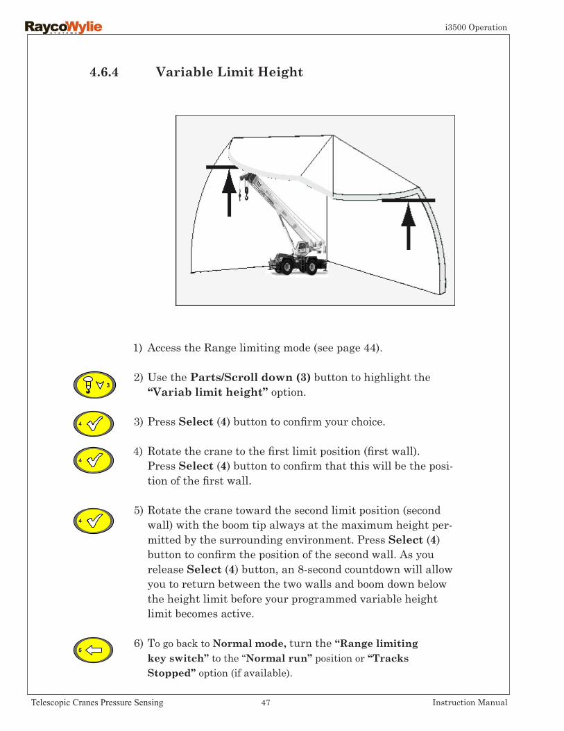
1) Access the Range limiting mode (see page 44).
2) Use the Parts/Scrolldown(3) button to highlight the ‘‘Variablimitheight’’option.
3) Press Select (4) button to confirm your choice.
4) Rotate the crane to the first limit position (first wall). Press Select (4) button to confirm that this will be the posi- tion of the first wall.
5) Rotate the crane toward the second limit position (second wall) with the boom tip always at the maximum height per- mitted by the surrounding environment. Press Select (4) button to confirm the position of the second wall. As you release Select (4) button, an 8-second countdown will allow you to return between the two walls and boom down below the height limit before your programmed variable height limit becomes active.
6) To go back to Normal mode, turn the ‘‘Range limiting keyswitch’’to the ‘‘Normalrun’’ position or ‘‘Tracks Stopped’’option (if available).
4.6.4 Variable Limit Height
i3500 Operation

1) Access the Range limiting mode (see page 44).
2) Use the Parts/Scrolldown(3) button to highlight the ‘‘Variablimitradius’’option.
3) Press Select (4) button to confirm your choice.
4) Rotate the crane to the first limit position (first wall). Press Select (4) button to confirm that this will be the posi- tion of the first wall.
5) Rotate the crane toward the second limit position (second wall) with the boom tip always at the maximum radius per- mitted by the surrounding environment. Press Select (4) button to confirm the position of the second wall. As you release Select (4) button, an 8 second countdown will allow you to return between the two walls and boom up within the allowed radius limit before your programmed variable radius limit becomes active.
6) To go back to Normal mode, turn the ‘‘Range limiting keyswitch’’to the ‘‘Normalrun’’ position or ‘‘Tracks Stopped’’option (if available).
4.6.5 Variable Limit Radius
48Telescopic Cranes Pressure Sensing Instruction Manual
i3500 Troubleshooting

This page has been intentionally left blank
49Telescopic Cranes Pressure Sensing Instruction Manual
i3500 Troubleshooting

This section provides technical troubleshooting support. It will address most frequently asked questions that repair personnel may have when installing, repairing or performing maintenance on the i3500 system.
5.0 Diagnostic&Troubleshooting
5.1 DiagnosticMenu
A diagnostic menu provides information on the sys-tems status and the state of all connected sensors.To access the diagnostic menu:
Press Mode (1) button
Use the Hoist/Scroll up (2) or Parts/Scrolldown(3) button to highlight your the diagnostic option.
Press Select (4) button to enter the diagnostic menu.
or
The information provided by the diagnostic menu has been divided into sev-eral menu pages. Each page applies to one type of sensor at the time or one particular type of information. The different menu pages available are: angle/length, load, relay, general info (for a specific type of calibration e.g. telescopic multi-point), rotation as well as the addresses of all sensors detected by the i3500 system. Regardless of system configuration, a minimum of three menu pages are always provided: angle/length, general info and detected addresses. Additional pages are optional and are only shown if one or more sensors are enabled (refer to the option enable/disable I/O in the calibration menu). The use of the Scroll Up/Down arrow buttons will allow the user to scroll in the menu. When pressing simultaneously on the Scroll Upor Down arrow button and the key, the display will move from one page to the next. Pressing the key will show calibration details and also the original software version of the highlighted sensor.
Warning! Troubleshooting shall be performed by a qualified technician or by an operator with assistance of a RaycoWylie Service technician.
• This feature is not available for all sensors.
• Pressing the Escape button takes you to the previous menu or exits the diagnostic mode.
50Telescopic Cranes Pressure Sensing Instruction Manual
i3500 Troubleshooting

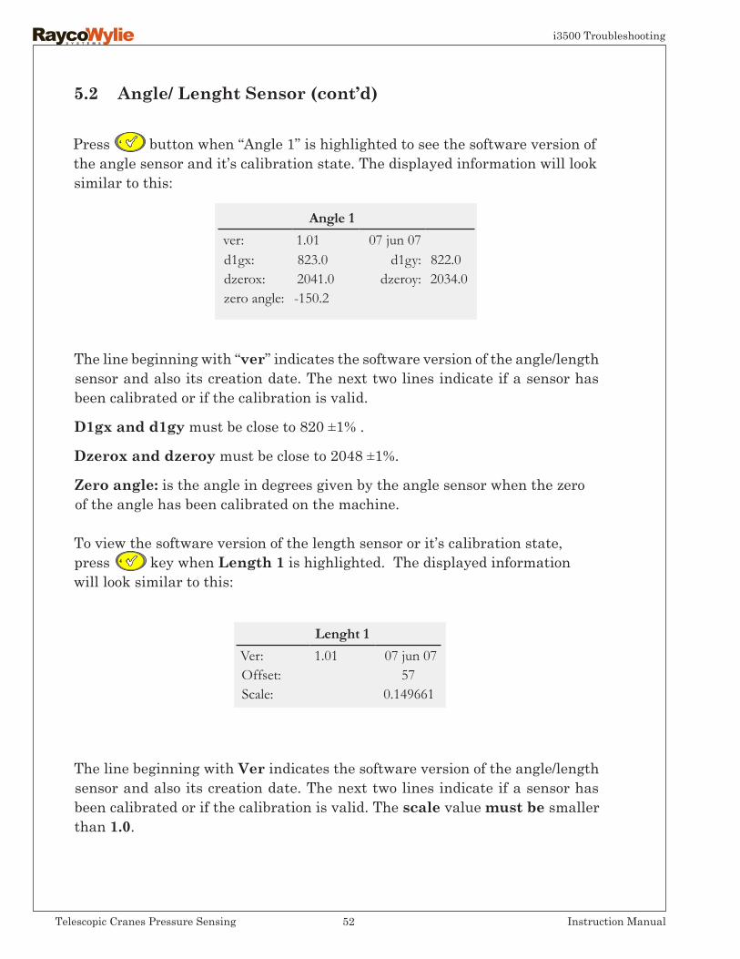
Some applications have more than one angle or length sensor. In this case, all of the angle sensors are listed first then length sensors will follow. The first angle sensor to be listed is the one installed closest to the main boom base.
Referring to the example above for the Angle 1 sensor:Values Ain 1 and Ain 2 vary depending on the inclinometers in the X and in Yaxes that are used to calculate the angle. These values are normally between 1200 and 2900 bits.Dr+:represents the D.C voltage level of excitation on the angle/ length card and must be close to 5.00 Volts.
When the multiple reel option is required every angle/length card has an ATB option that can be activated by dip switch # 4. For the angle/length card, which is not monitoring the ATB, N/A is shown under a2b instead of 0 or 1, indicating that it’s not available on this card.Value 0 represents a safe condition while value 1 will represent a two-block condition.
As shown on the above table, for the length 1 sensor, the value ain1 represents the boom extension value in bits. It may vary between around 50 and 975 bits. The length 1 sensor ain2 value is reserved for future expansion.
sensor ain 1 ain 2 dr + a2bAngle 1: 1428 1503 4.99 0Length 1: 203 N/A 4.99 0
In the diagnostic menu, this is the typical displayed information:
5.2 Angle/ Lenght Sensor
Angle 1 and Length 1 sensors are physically located on the sameelectronic board.
51Telescopic Cranes Pressure Sensing Instruction Manual
i3500 Troubleshooting
5.2 Angle/LenghtSensor(cont’d)
The line beginning with “ver” indicates the software version of the angle/length sensor and also its creation date. The next two lines indicate if a sensor has been calibrated or if the calibration is valid.
D1gxandd1gy must be close to 820 ±1% .
Dzeroxanddzeroy must be close to 2048 ±1%.
Zeroangle: is the angle in degrees given by the angle sensor when the zero of the angle has been calibrated on the machine.
To view the software version of the length sensor or it’s calibration state, press key when Length 1 is highlighted. The displayed information will look similar to this:
The line beginning with Ver indicates the software version of the angle/length sensor and also its creation date. The next two lines indicate if a sensor has been calibrated or if the calibration is valid. The scale value must be smaller than 1.0.
Lenght 1 Ver: 1.01 07 jun 07Offset: 57Scale: 0.149661
Press button when “Angle 1” is highlighted to see the software version of the angle sensor and it’s calibration state. The displayed information will look similar to this:
Angle 1 ver: 1.01 07 jun 07d1gx: 823.0 d1gy: 822.0dzerox: 2041.0 dzeroy: 2034.0zero angle: -150.2
52Telescopic Cranes Pressure Sensing Instruction Manual
i3500 Troubleshooting

Load 1 Ver: 1.01 07 jun 07Offset: 373Scale: 0.1421131
P1 and P2 values indicate the state of proximity sensors (prox 1 and prox 2).P1 and P2 are used to detect target for the rope direction sensor option, this option is not available for the telescopic crane pressure sensing, multi-point version. To know the software version of a pressure sensor or its calibration state, press when load 1 is highlighted. The displayed information will look similar to this:
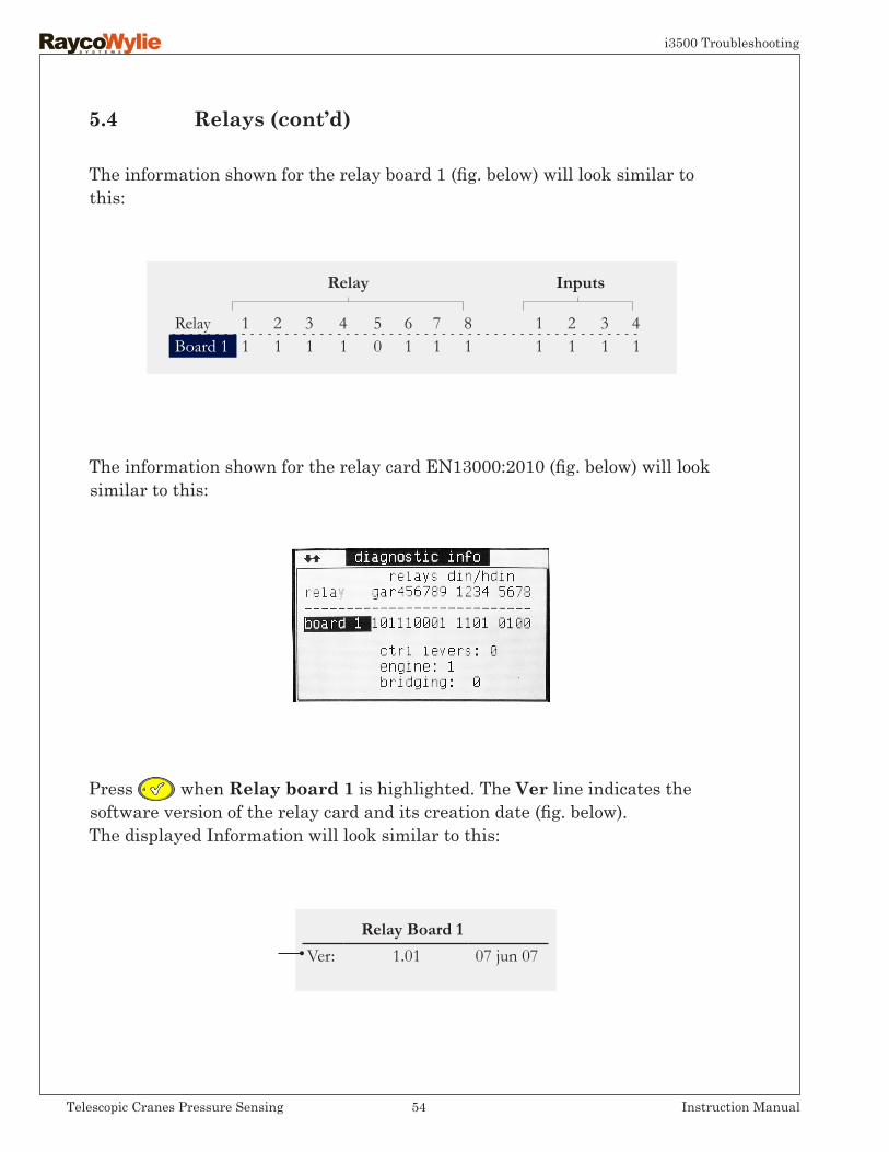
The information shown for the relay cards is divided into two blocks:The Relay block represents the individual state of every relay. Value “0” indicates that the relay coil is energized whereas “1” indicates that it’s not energized. The Inputs block represents the state of the 4 DIN inputs. Value
“0” represents an active input. A maximum of 4 relay cards can be installed.
The line beginning with Ver indicates the software version of the pressure sensor and its creation date. The next two lines indicate if a sensor has been calibrated or if the calibration is valid. The scale value must be smaller than 1.0.
The ain value represents cylinder pressure measured in bits by the pressure sensor. It can reach a maximum of 4095 bits. The Dr + column is a regulated D.C. voltage level for the excitation of the pressure sensor and must be close to 5.00 VDC.
5.3 Pressure Sensors
Sensor ain dr+ p1 p2Load 1 1325 4.96 1 1Load 2 1109 4.98 1 1
5.4 Relays
53Telescopic Cranes Pressure Sensing Instruction Manual
i3500 Troubleshooting
5.4 Relays(cont’d)
The information shown for the relay card EN13000:2010 (fig. below) will look similar to this:
The information shown for the relay board 1 (fig. below) will look similar to this:
Press when Relay board 1 is highlighted. The Ver line indicates the software version of the relay card and its creation date (fig. below).The displayed Information will look similar to this:
Relay Board 1 Ver: 1.01 07 jun 07
Relay 1 2 3 4 5 6 7 8 1 2 3 4Board 1 1 1 1 1 0 1 1 1 1 1 1 1
Relay Inputs
54Telescopic Cranes Pressure Sensing Instruction Manual
i3500 Troubleshooting

5.5 SlewSensors(rotation option)
5.6 Detectedaddresses:
The Ver line indicates the software version of the rotation interface and its creation date (see fig. above).
rot: Represents the rotation pointer and varies from 0° to 359° (Azimut)
zero pos.: Represents an offset value between the absolute zero and the relatif zero establish at the moment of calibration .
rot. dir.: Represents the rotation sense.
encodertype:Represents the type of sensor.
This menu page provides the sensor addresses on the CANnetwork detected by the i3500 system. Addresses remain in memory as long as the system is powered even if a sensor stops communicating.
The displayed information will look similar to this:
Note: The informa-tion depicted here may differ depen-ding on the rota-tion sensor used.
Consult the i3500 Calibration Manual to view additional Diagnostic Menu pages with information related to internal calibration parameters.
55Telescopic Cranes Pressure Sensing Instruction Manual
i3500 Troubleshooting
During start up and other operation processes, the i3500 system analyses all interactions between internal peripherals (memories, controllers, extension cards, etc.) and also external ones (physical cards linked to the Canbus network)
If you have any questions or need technical assistance, please contact our Technical Service Department at RaycoWylie.
5.7 ErrorMessagesandtheuseofthe key
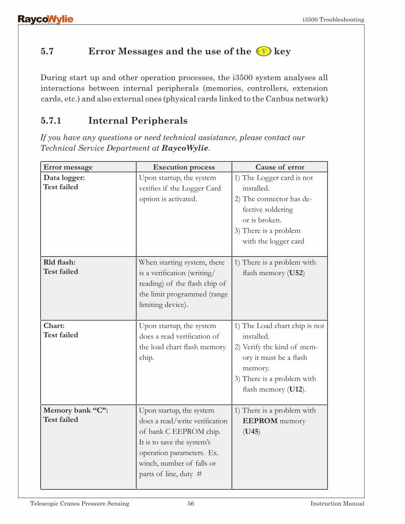
5.7.1 Internal Peripherals
Error message Execution process Cause of errorData logger:Test failed
Upon startup, the system verifies if the Logger Cardoption is activated.
1) The Logger card is not installed.2) The connector has de- fective soldering or is broken.3) There is a problem with the logger card
Rld flash:Test failed
When starting system, thereis a verification (writing/reading) of the flash chip of the limit programmed (range limiting device).
1) There is a problem with flash memory (U52)
Chart:Test failed
Upon startup, the system does a read verification of the load chart flash memory chip.
1) The Load chart chip is not installed.2) Verify the kind of mem- ory it must be a flash memory.3) There is a problem with flash memory (U12).
Memory bank ‘‘C”:Test failed
Upon startup, the system does a read/write verification of bank C EEPROM chip. It is to save the system’s operation parameters. Ex. winch, number of falls or parts of line, duty #
1) There is a problem with EEPROM memory (U45)
56Telescopic Cranes Pressure Sensing Instruction Manual
i3500 Troubleshooting

5.7.1 InternalPeripherals(cont’d)
Error message Execution process Cause of errorClock: Test failed
The Logger option must be activated. The System regularly verifies if the seconds are moving. If time does not change then there is a problem.
1) Verify if the black plastic cap is installed on the logger card (contains battery and crystal).2) There is a problem with the logger card.
Memory bank “A”:Test failed
Upon startup, the system does a read verification of bank A EEPROM chip. It’s used to save the calibration data.
1) There is a problem with memory EEPROM (U44).
RAM:Test failed
Upon startup, the system does a read/write verification of RAM chip. This is a volatile memory.
1) There is a problem with RAM memory (U3). With Logger option, the cause is RAM memory (U5). - if system is behaving strangely, - if system initializes often during operation mode, - if system never starts.
Not calibrated There is no calibration for the selected duty.
1) The calibration must be done.
General failure orCANbus
Can Bus controller verification.
1) There is a problem with CANbus controller, either SJA1000 or MCP2515 (U29).
Multi-languagesnot supp.
Verification of programmed load chart in the system. Must be multi-languages. This option can support up to 10 languages.
1) The programmed load- chart is not compatible.
57Telescopic Cranes Pressure Sensing Instruction Manual
i3500 Troubleshooting
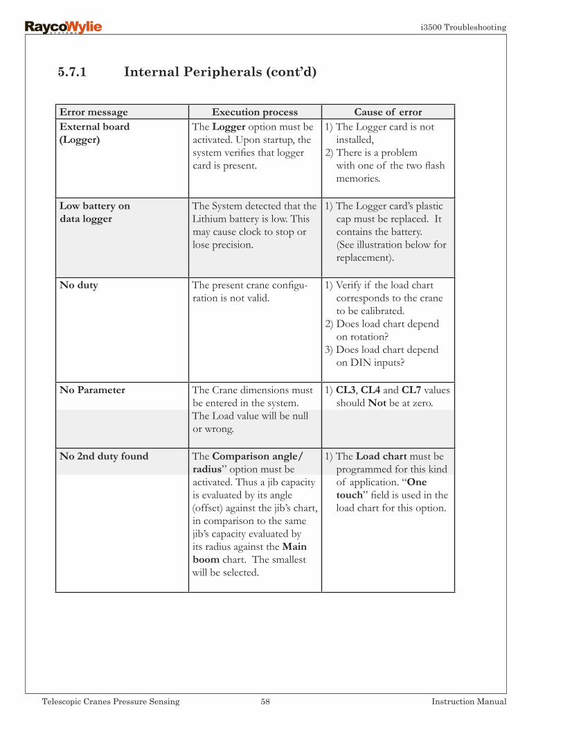
Error message Execution process Cause of errorExternal board(Logger)
The Logger option must be activated. Upon startup, the system verifies that logger card is present.
1) The Logger card is not installed,2) There is a problem with one of the two flash memories.
Low battery ondata logger
The System detected that the Lithium battery is low. This may cause clock to stop or lose precision.
1) The Logger card’s plastic cap must be replaced. It contains the battery. (See illustration below for replacement).
No duty The present crane configu-ration is not valid.
1) Verify if the load chart corresponds to the crane to be calibrated.2) Does load chart depend on rotation?3) Does load chart depend on DIN inputs?
No Parameter The Crane dimensions must be entered in the system. The Load value will be null or wrong.
1) CL3, CL4 and CL7 values should Not be at zero.
No 2nd duty found The Comparison angle/radius” option must be activated. Thus a jib capacity is evaluated by its angle (offset) against the jib’s chart, in comparison to the same jib’s capacity evaluated by its radius against the Main boom chart. The smallest will be selected.
1) The Load chart must be programmed for this kind of application. “One touch” field is used in the load chart for this option.
5.7.1 InternalPeripherals(cont’d)
58Telescopic Cranes Pressure Sensing Instruction Manual
i3500 Troubleshooting
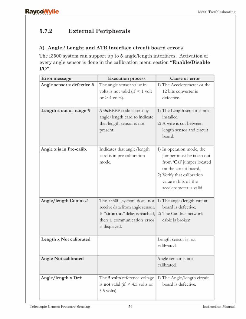
Error message Execution process Cause of errorAngle sensor x defective # The angle sensor value in
volts is not valid (if < 1 volt or > 4 volts).
1) The Accelerometer or the 12 bits converter is defective.
Length x out of range # A 0xFFFF code is sent by angle/length card to indicate that length sensor is not present.
1) The Length sensor is not installed2) A wire is cut between length sensor and circuit board.
Angle x is in Pre-calib. Indicates that angle/length card is in pre-calibration mode.
1) In operation mode, the jumper must be taken out from ‘Cal’ jumper located on the circuit board.2) Verify that calibration value in bits of the accelerometer is valid.
Angle/length Comm # The i3500 system does not receive data from angle sensor. If ‘‘time out’’ delay is reached, then a communication error is displayed.
1) The angle/length circuit board is defective,2) The Can bus network cable is broken.
Length x Not calibrated Length sensor is not calibrated.
Angle Not calibrated Angle sensor is not calibrated.
Angle/length x Dr+ The 5 volts reference voltage is not valid (if < 4.5 volts or 5.5 volts).
1) The Angle/length circuit board is defective.
The i3500 system can support up to 5 angle/length interfaces. Activation of every angle sensor is done in the calibration menu section ‘‘Enable/DisableI/O’’.
A) Angle / Lenght and ATB interface circuit board errors
5.7.2 External Peripherals
59Telescopic Cranes Pressure Sensing Instruction Manual
i3500 Troubleshooting

Error message Execution process Cause of errorload x out of range The Angle sensor value in
bits is not valid(if < 150 or > 3935).
load x out not calibrated The Load sensor is not cali-brated.
load x Dr+ The 5 volts reference voltage is not valid (if < 4.5volts or > 5.5 volts).
The Load card is defective.
load x Communication The i3500 system does not receive data from pressure sensor. If “time out” delay is reached, then a communication error is displayed.
1) The Load card is defective,2) The Can Bus network cable is broken.
Error message Execution process Cause of errorrelay xCommunication
i3500 system does not receive data from relay card. If “time out” delay is reached, then a commu-nication error is displayed.
1) The Relay card is defective,2) The Can Bus network cable is broken.
The i3500 system can support up to 4 load circuit boards. Activation of every load sensor is done in the calibration menu section ‘‘Enable/DisableI/O’’.
The i3500 system can support up to 4 relay cards. Activation of every relay card is done in the calibration menu section “I/O activate/deactivate”.
B)Loadinterfacecircuitboarderrors
C)Relay and digital input interface board errors
There is no automatic test for the relay contacts on the relay circuit board. Therefore, if a relay becomes defective there may not be a warning. Periodically, the operator should test the lockout system.
60Telescopic Cranes Pressure Sensing Instruction Manual
i3500 Troubleshooting

Error message Execution process Cause of errorCant x Not Cal An appropriate, analogical
sensor is not calibratedAn appropriate, analogical sensor is not calibrated
Generic Dr + The 5 volts reference voltage is not valid (if < 4.5 volts or > 5.5 volts).
1) The Generic card is defective.
GenericCommunication
The i3500 system does not receive data from generic card. If “time out” delay is reached, then a communication error is displayed.
1) The Generic card is defective.2) The Can Bus network cable is broken.
Load xCommunication
The i3500 system does not receive data from pressure sensor. If “time out” delay is reached, then a communication error is displayed.
1) The Relay card is defective2) The Can Bus network cable is broken.
The i3500 system can support up to 4 generic cards: One for wind speed, one for inclination level, one for absolute rotation and another one for analogical output. Activation of every generic card is done in the calibration menu section ‘‘Enable/DisableI/O’’.
D)Genericinterfaceboarderrors
Relative rotationThe i3500 system can support only one (1) rotation card. There are two differ-ent kinds: a relative one and an absolute one. Activation of rotation card is done in the calibration menu section ‘‘Enable/DisableI/O’’.
E)Rotationinterfaceboarderrors
Error message Execution process Cause of errorLoad encoder cable A GND wire indicates
that the cable between the encoder and the rotation card is not cut. If the cable breaks, this wire will become open. Then the rotation card will send an error message to the i3500 system
1) Replace cable between encoder and rotation card.
Encoder ratio No ratio has been entered. 1) Put a different value than 0.
Encoder prox. position. Proximity is not detected in configured position by i3500 system.
1) The Proximity is defective.
61Telescopic Cranes Pressure Sensing Instruction Manual
i3500 Troubleshooting
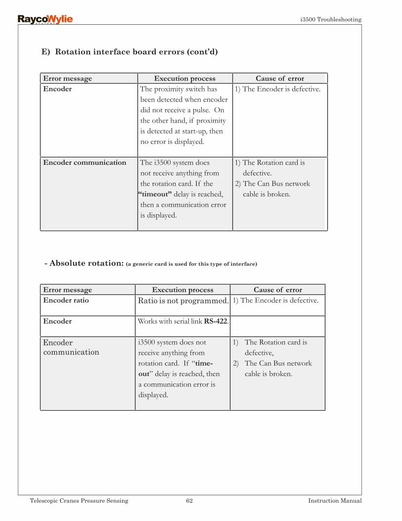
E)Rotationinterfaceboarderrors(cont’d)
-Absoluterotation:(agenericcardisusedforthistypeofinterface)
Error message Execution process Cause of errorEncoder The proximity switch has
been detected when encoder did not receive a pulse. On the other hand, if proximity is detected at start-up, then no error is displayed.
1) The Encoder is defective.
Encoder communication The i3500 system does not receive anything from the rotation card. If the
“timeout” delay is reached, then a communication error is displayed.
1) The Rotation card is defective.2) The Can Bus network cable is broken.
Error message Execution process Cause of errorEncoder ratio Ratio is not programmed. 1) The Encoder is defective.
Encoder Works with serial link RS-422.
Encodercommunication
i3500 system does not receive anything from rotation card. If “time- out” delay is reached, then a communication error is displayed.
1) The Rotation card is defective,2) The Can Bus network cable is broken.
62Telescopic Cranes Pressure Sensing Instruction Manual
i3500 Troubleshooting

Inspect at regular intervals the following:
• All cables for cuts or damage as well as all connectors for corroded contacts. • The attachment of the cable reel at the end of the boom.• The plunger of the ATB switch for excessive corrosion.• Excessive wear of brushes in the reeling drum.• Evidence of leakage at the pressure transducer connection.• Functionality of the bridging device.• Operation of the lockout relays.
6.2 Periodicalinspections(every6months)
-6-
Inspection, Testing & Maintenance
• At system power up, check if all alarm lights are on, buzzer sounds and lockout are activated.
• Verify that the system has been properly configured.• Verify the accuracy of the clock.• Verify that no error has been detected by the system.• Verify the weight of the hook block (must be consistent with last check).• Verify the radius according to the boom selection. The displayed radius
must be between 0 and 10% greater than the actual radius or in accordance with current regulations.
• Verify that the capacity displayed conforms to the capacity chart of the crane manufacturer.
• Verify the functionality of the ATB if fitted.
6.1 FrequentInspections(Atthebeginningofeachshift duringwhichacraneisused)
Warning! Any deficiencies shall be examined and a decision must be made as to whether they constitute a hazard before using the machine.
63Telescopic Cranes Pressure Sensing Instruction Manual
i3500 Maintenance
• Position and level the machine.• Testing personnel must be a qualified person for the crane and the i3500’s
system.• The crane and the system must be configured properly.• The load chart must be respected.• A known weight accurate to ± 1% and equal to the maximum capacity at
near maximum radius should be used to test the alarm and the accuracy of load indication.
• Another known weight accurate to ± 1% and equal to the maximum capacity at near minimum radius should be used to test the alarm and the accuracy of load indication.
• Rig with enough parts of line to lift a large weight.• Measure and record the radius and the hook weight.• Note the displayed radius, length, hook weight, parts of line and capacity
on the i3500 display unit.• Lift the large weight.• Record the actual weight with the hook and rigging attachment.• Note the average, the low and the high value.• Perform a hoist up and stop and note the same data.• Note the actual and displayed radius.• Lower the load. • RaycoWylie recommends as a good practice that all test records are
signed and dated, and that a copy of the latest test be available at all times.
6.3 Rated Load Test
64Telescopic Cranes Pressure Sensing Instruction Manual
i3500 Maintenance
Preventive maintenance
• Your i3500 system has been designed to operate over long periods of time with minimum maintenance. However, continuous satisfactory operation depends upon system’s care and cleaning.
• To clean the display’s surface, use mild soap or mild window cleaners and a clean soft cloth.
• Replace all cables showing cut or damage or corroded connector contacts.
• Replace reeling drum’s brushes if they show excessive wear.
• Replace ATB switch if the plunger shows excessive corrosion.
6.4 Maintenance
Replacement parts must be obtained from RaycoWylie as original parts, unless approved and authorized as an equivalent by a Service technician of RaycoWylie.
• To keep the waterproofness of the i3500’s display the back cover must be tighten following an X pattern.
• Your i3500 system requires no additional lubrication.
Important: If condensation appears in the screen of the display unit, open the cover in a dry place and let it air dry for a day.
Important: Do not use pressure steam on the i3500 display box, junction boxes, angle sensor, load cells or on any connectors. This could result in moisture in the connectors and can cause eventual sensor failure.
65Telescopic Cranes Pressure Sensing Instruction Manual
i3500 Maintenance

• Place crane where it will cause the least interference with other equipment or operations in the area.
• Set all controls in the off position and ensure all operating features are secured from inadvertent motion.
• Render starting means inoperative.
• Lower the boom to the ground, if possible, or otherwise secure against dropping.
• Lower the load block to the ground or otherwise secure against dropping.
• Relieve hydraulic oil pressure from all hydraulic circuits before loosening or removing hydraulic components.
• “Warning” or “Out of Order” signs shall be placed on the crane controls and be removed only by authorized personnel.
• After adjustments and repair have been made, the crane shall not be re- turned to service until all guards have been reinstalled, trapped air removed from the hydraulic system and safety devices reactivated. The instructions shall be provided by the crane manufacturer for the removal of air from hydraulic circuits.
6.5 Maintenance procedure
Before adjustments and repairs are started on a crane, the following precautions shall be taken as applicable:
66Telescopic Cranes Pressure Sensing Instruction Manual
i3500 Maintenance

6.6 Adjustments and Repairs
• Adjustment shall be made within RaycoWylie’s specified tolerance to maintain the correct functioning of all components.
• Should you need replacement parts for maintenance and repairs on our equipments, please contact our Service Department at RaycoWylie.
• Any hazardous conditions disclosed by the inspection requirements shall be corrected before operation of the crane is resumed.
Important: Adjustments and repairs shall be done only by qualified personnel.
If you have any questions or need technical assistance, please contact our Technical Service Department at RaycoWylie quoting the infor-mation found on the serial number label of your i3500 system.
67Telescopic Cranes Pressure Sensing Instruction Manual
i3500 Maintenance

68Telescopic Cranes Pressure Sensing Instruction Manual
i3500 Maintenance
This page has been intentionally left blank

Notes
69Telescopic Cranes Pressure Sensing Instruction Manual
i3500 Maintenance