I2c interfacing raspberry pi to arduino
20
Connecting Raspberry Pi to Arduino using I2C Raspberry Pi This work is licensed under the Creative Commons Attribution- ShareAlike 4.0 International License. To view a copy of this license, visit http://creativecommons.org/licenses/b y-sa/4.0/. Revision 2 Companion Github
-
Upload
mike-ochtman -
Category
Devices & Hardware
-
view
5.825 -
download
1
Transcript of I2c interfacing raspberry pi to arduino
Connecting Raspberry Pi to
Arduino using I2C
Raspberry Pi
This work is licensed under the Creative Commons Attribution-ShareAlike 4.0 International License. To view a copy of this license, visit http://creativecommons.org/licenses/by-sa/4.0/.
Revision 2
Companion Github

What is I2C?
The Inter-IC Bus (I-IC or I2C) standard defines the hardware and electrical characteristics of the interface between nearby devices using only two wires (and a third for ground reference).
SMBus was introduced by Intel as a tight subset of I2C, strictly defining the interface between devices.
It is commonly used in televisions, computer components, and many ADC and DAC and GPS devices.
The Raspberry Pi most commonly uses an SMBus implementation in Python 2.x, and this is what we will concentrate on in this document.

Connecting DevicesIdentify SDA, SCL, and GND pins on both Raspberry Pi and the Arduino.Connect SDA to SDA, SCL to SCL, and GND to GND between the two devices.
It is possible to connect the two devices directly to one another without a level shifter, but it is not best practice. I2C levels for a low signal is 0.3Vcc and for a high, 0.7Vcc. With the Raspberry Pi being a 3.3V device and the Arduino requiring 5V for Vcc, a logic level 'high' coming from the 3.3V Raspberry Pi is slightly below the 0.7*5= 3.5V required for a definite logic 'high' in the Arduino.
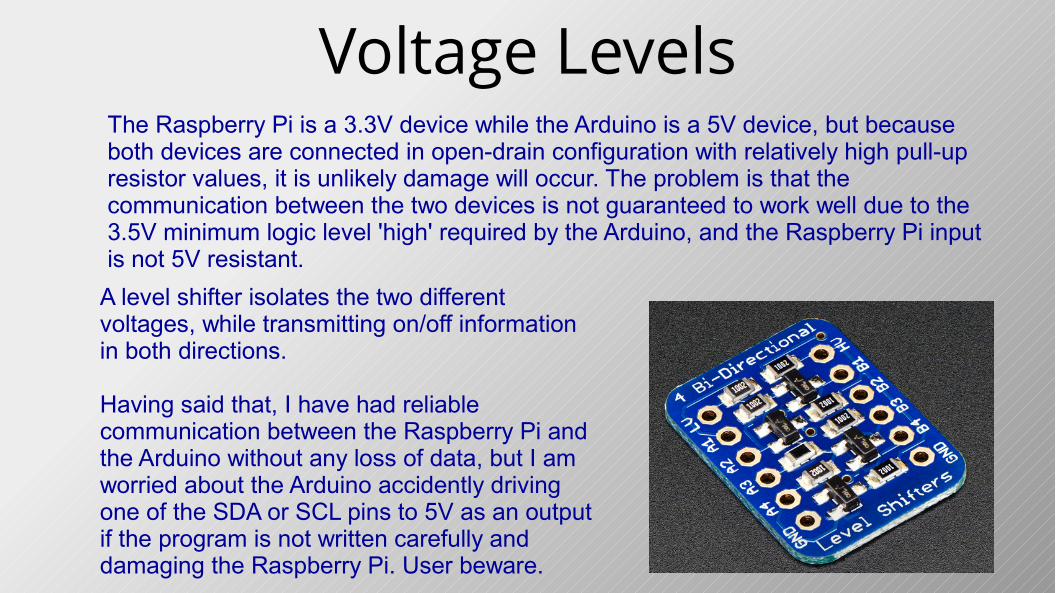
Voltage LevelsThe Raspberry Pi is a 3.3V device while the Arduino is a 5V device, but because both devices are connected in open-drain configuration with relatively high pull-up resistor values, it is unlikely damage will occur. The problem is that the communication between the two devices is not guaranteed to work well due to the 3.5V minimum logic level 'high' required by the Arduino, and the Raspberry Pi input is not 5V resistant.
A level shifter isolates the two different voltages, while transmitting on/off information in both directions.
Having said that, I have had reliable communication between the Raspberry Pi and the Arduino without any loss of data, but I am worried about the Arduino accidently driving one of the SDA or SCL pins to 5V as an output if the program is not written carefully and damaging the Raspberry Pi. User beware.

I2C Level ShifterThis rather complicated-looking circuit creates a bi-directional bus that can automatically translate 3.3V bus signals into 5V signals and vice versa at full bus speed. This is one of the simplest and cheapest level shifters and can easily be built on a breadboard or soldered in a few minutes on any of the prototyping stripboards available.
On the next slide, we look at this circuit in detail

The Level ShifterIsolating one of the two identical bus lines, we find an enhancement-mode n-channel MOSFET the star of the show. It's Gate is tied directly to the low-voltage Vcc. A pull-up resistor connects the High voltage side to the Drain, and another pulls the Source up to the Low voltage side.S1 and S2 simulate the Open-Drain connection that drives the bus at the microcontroller.
With both switches open, Gate and Source are at the same potential so the transistor is turned off. Both sides are pulled up to their respective Vcc.
With S1 closed and S1 open, the source is pulled down to 0V, taking Vgs (Gate-Source Voltage) above the threshold and turning the transistor on hard. This pulls the Drain side down to 0V as well.
With S2 closed and S1 open, Drain is pulled to 0V and the internal diode is forward-biased by the 3.3V, dropping the source to around 0.6V. This is enough to pull Vgs again beyond the threshold, opening the transistor and dragging the bus down to 0V.
With both switches closed, both sides will be at 0V.
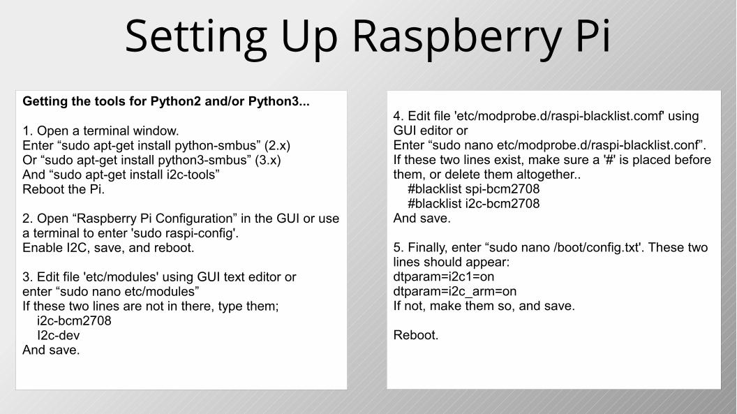
Setting Up Raspberry PiGetting the tools for Python2 and/or Python3...
1. Open a terminal window.Enter “sudo apt-get install python-smbus” (2.x)Or “sudo apt-get install python3-smbus” (3.x)And “sudo apt-get install i2c-tools”Reboot the Pi.
2. Open “Raspberry Pi Configuration” in the GUI or use a terminal to enter 'sudo raspi-config'.Enable I2C, save, and reboot.
3. Edit file 'etc/modules' using GUI text editor or enter “sudo nano etc/modules”If these two lines are not in there, type them; i2c-bcm2708 I2c-devAnd save.
4. Edit file 'etc/modprobe.d/raspi-blacklist.comf' using GUI editor orEnter “sudo nano etc/modprobe.d/raspi-blacklist.conf”.If these two lines exist, make sure a '#' is placed before them, or delete them altogether.. #blacklist spi-bcm2708 #blacklist i2c-bcm2708And save.
5. Finally, enter “sudo nano /boot/config.txt'. These two lines should appear:dtparam=i2c1=ondtparam=i2c_arm=onIf not, make them so, and save.
Reboot.
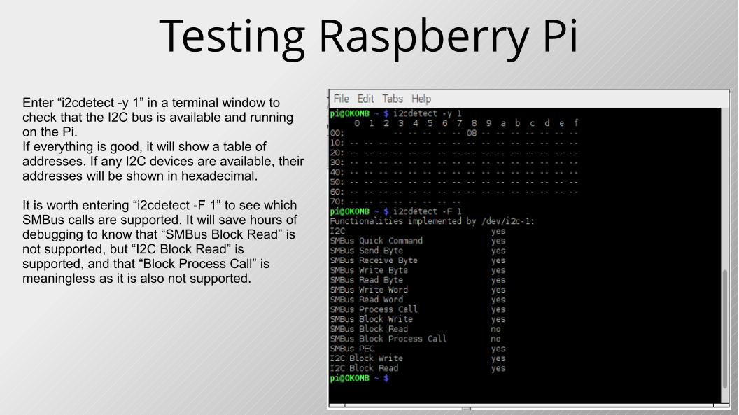
Testing Raspberry PiEnter “i2cdetect -y 1” in a terminal window to check that the I2C bus is available and running on the Pi.If everything is good, it will show a table of addresses. If any I2C devices are available, their addresses will be shown in hexadecimal.
It is worth entering “i2cdetect -F 1” to see which SMBus calls are supported. It will save hours of debugging to know that “SMBus Block Read” is not supported, but “I2C Block Read” is supported, and that “Block Process Call” is meaningless as it is also not supported.
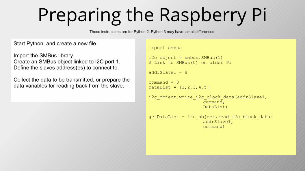
Preparing the Raspberry PiStart Python, and create a new file.
Import the SMBus library.Create an SMBus object linked to I2C port 1.Define the slaves address(es) to connect to.
Collect the data to be transmitted, or prepare the data variables for reading back from the slave.
These instructions are for Python 2. Python 3 may have small differences.
import smbus
i2c_object = smbus.SMBus(1)# Link to SMBus(0) on older Pi
addrSlave1 = 8
command = 0dataList = [1,2,3,4,5]
i2c_object.write_i2c_block_data(addrSlave1,command,DataList)
getDataList = i2c_object.read_i2c_block_data(addrSlave1,command)
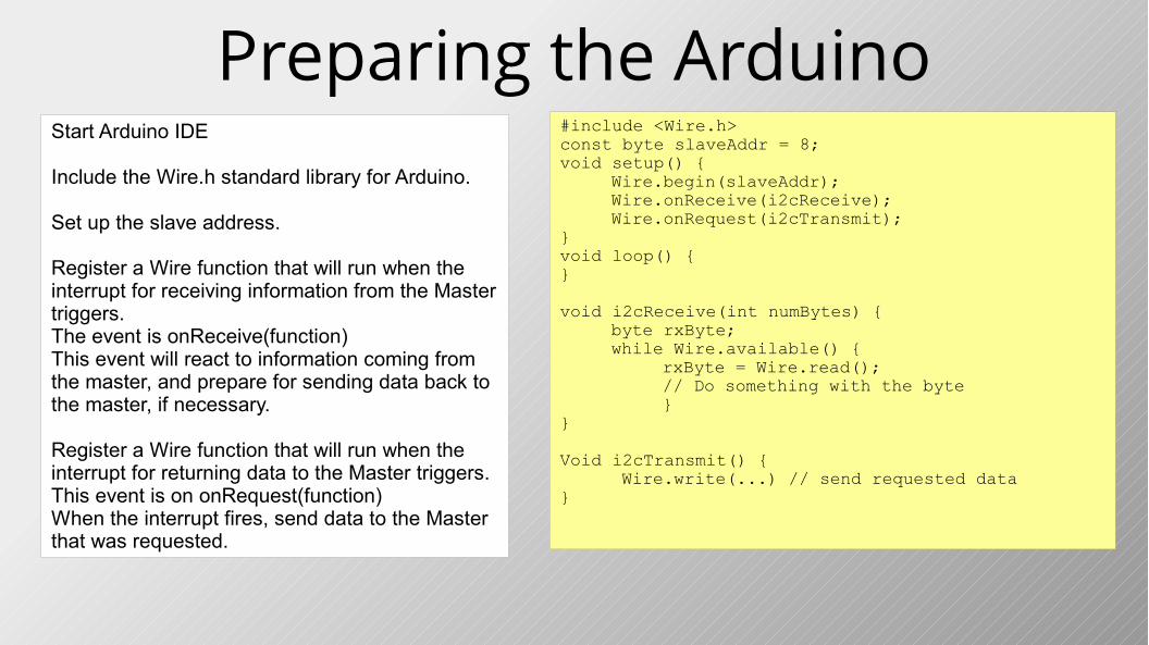
Preparing the ArduinoStart Arduino IDE
Include the Wire.h standard library for Arduino.
Set up the slave address.
Register a Wire function that will run when the interrupt for receiving information from the Master triggers.The event is onReceive(function)This event will react to information coming from the master, and prepare for sending data back to the master, if necessary.
Register a Wire function that will run when the interrupt for returning data to the Master triggers.This event is on onRequest(function)When the interrupt fires, send data to the Master that was requested.
#include <Wire.h>const byte slaveAddr = 8;void setup() {
Wire.begin(slaveAddr);Wire.onReceive(i2cReceive);Wire.onRequest(i2cTransmit);
}void loop() {}
void i2cReceive(int numBytes) {byte rxByte;while Wire.available() {
rxByte = Wire.read();// Do something with the byte}
}
Void i2cTransmit() { Wire.write(...) // send requested data
}
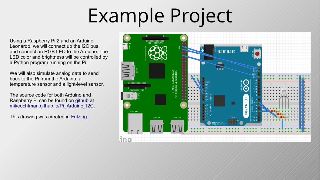
Example ProjectUsing a Raspberry Pi 2 and an Arduino Leonardo, we will connect up the I2C bus, and connect an RGB LED to the Arduino. The LED color and brightness will be controlled by a Python program running on the Pi.
We will also simulate analog data to send back to the Pi from the Arduino, a temperature sensor and a light-level sensor.
The source code for both Arduino and Raspberry Pi can be found on github at mikeochtman.github.io/Pi_Arduino_I2C.
This drawing was created in Fritzing.
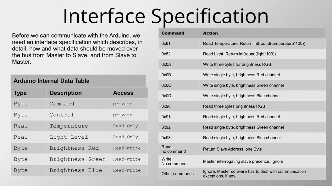
Interface SpecificationBefore we can communicate with the Arduino, we need an interface specification which describes, in detail, how and what data should be moved over the bus from Master to Slave, and from Slave to Master.
Type Description Access
Byte Command private
Byte Control private
Real Temperature Read Only
Real Light Level Read Only
Byte Brightness Red Read/Write
Byte Brightness Green Read/Write
Byte Brightness Blue Read/Write
Arduino Internal Data Table
Command Action
0x81 Read Temperature. Return int(round(temperature*100))
0x82 Read Light. Return int(round(light*100))
0x0A Write three bytes for brightness RGB
0x0B Write single byte, brightness Red channel
0x0C Write single byte, brightness Green channel
0x0D Write single byte, brightness Blue channel
0x90 Read three bytes brightness RGB
0x91 Read single byte, brightness Red channel
0x92 Read single byte, brightness Green channel
0x93 Read single byte, brightness Blue channel
Read, no command Return Slave Address, one Byte
Write,No command
Master interrogating slave presence. Ignore
Other commands Ignore. Master software has to deal with communication exceptions, if any.
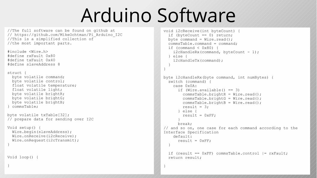
Arduino Software//The full software can be found on github at// https://github.com/MikeOchtman/Pi_Arduino_I2C//This is a simplified collection of //the most important parts.
#include <Wire.h>#define rxFault 0x80#define txFault 0x40#define slaveAddress 8
struct { byte volatile command; byte volatile control; float volatile temperature; float volatile light; byte volatile brightR; byte volatile brightG; byte volatile brightB;} commsTable;
byte volatile txTable[32]; // prepare data for sending over I2C
Void setup() { Wire.begin(slaveAddress); Wire.onReceive(i2cReceive); Wire.onRequest(i2cTransmit); }
Void loop() {
}
void i2cReceive(int byteCount) { if (byteCount == 0) return; byte command = Wire.read(); commsTable.command = command; if (command < 0x80) { i2cHandleRx(command, byteCount - 1); } else { i2cHandleTx(command); }}
byte i2cHandleRx(byte command, int numBytes) { switch (command) { case 0x0A: if (Wire.available() == 3) commsTable.brightR = Wire.read(); commsTable.brightG = Wire.read(); commsTable.brightB = Wire.read(); result = 3; } else { result = 0xFF; } break;// and so on, one case for each command according to the Interface Specification default: result = 0xFF; }
if (result == 0xFF) commsTable.control |= rxFault; return result;
}
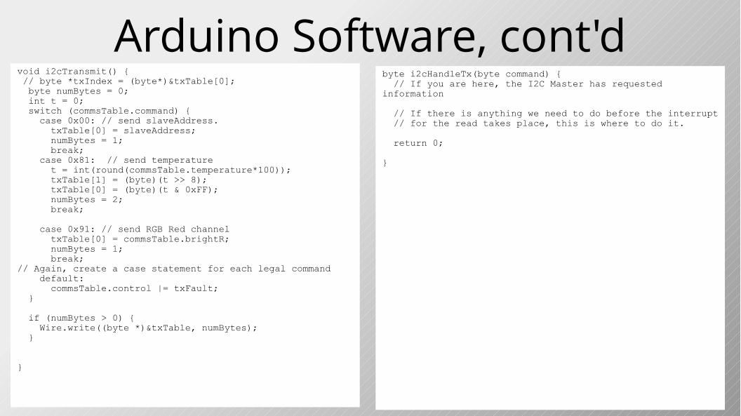
Arduino Software, cont'dbyte i2cHandleTx(byte command) { // If you are here, the I2C Master has requested information
// If there is anything we need to do before the interrupt // for the read takes place, this is where to do it.
return 0;
}
void i2cTransmit() { // byte *txIndex = (byte*)&txTable[0]; byte numBytes = 0; int t = 0; switch (commsTable.command) { case 0x00: // send slaveAddress. txTable[0] = slaveAddress; numBytes = 1; break; case 0x81: // send temperature t = int(round(commsTable.temperature*100)); txTable[1] = (byte)(t >> 8); txTable[0] = (byte)(t & 0xFF); numBytes = 2; break;
case 0x91: // send RGB Red channel txTable[0] = commsTable.brightR; numBytes = 1; break;// Again, create a case statement for each legal command default: commsTable.control |= txFault; }
if (numBytes > 0) { Wire.write((byte *)&txTable, numBytes); }
}
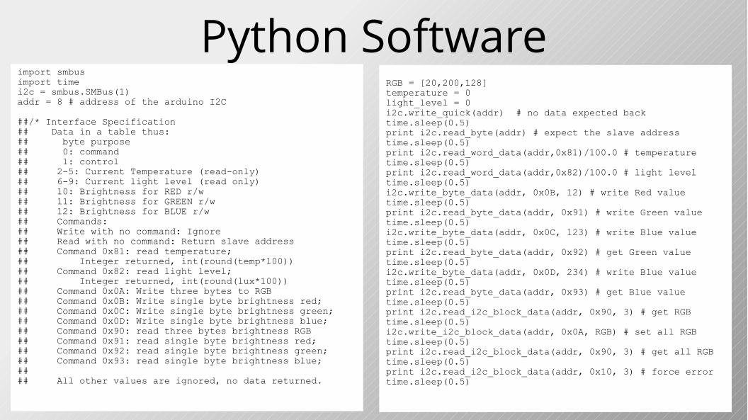
Python Softwareimport smbusimport timei2c = smbus.SMBus(1)addr = 8 # address of the arduino I2C
##/* Interface Specification## Data in a table thus:## byte purpose## 0: command## 1: control## 2-5: Current Temperature (read-only)## 6-9: Current light level (read only)## 10: Brightness for RED r/w## 11: Brightness for GREEN r/w## 12: Brightness for BLUE r/w## Commands:## Write with no command: Ignore## Read with no command: Return slave address## Command 0x81: read temperature; ## Integer returned, int(round(temp*100))## Command 0x82: read light level;## Integer returned, int(round(lux*100))## Command 0x0A: Write three bytes to RGB## Command 0x0B: Write single byte brightness red;## Command 0x0C: Write single byte brightness green;## Command 0x0D: Write single byte brightness blue;## Command 0x90: read three bytes brightness RGB## Command 0x91: read single byte brightness red;## Command 0x92: read single byte brightness green;## Command 0x93: read single byte brightness blue;#### All other values are ignored, no data returned.
RGB = [20,200,128]temperature = 0light_level = 0i2c.write_quick(addr) # no data expected backtime.sleep(0.5)print i2c.read_byte(addr) # expect the slave addresstime.sleep(0.5)print i2c.read_word_data(addr,0x81)/100.0 # temperaturetime.sleep(0.5)print i2c.read_word_data(addr,0x82)/100.0 # light leveltime.sleep(0.5)i2c.write_byte_data(addr, 0x0B, 12) # write Red valuetime.sleep(0.5)print i2c.read_byte_data(addr, 0x91) # write Green valuetime.sleep(0.5)i2c.write_byte_data(addr, 0x0C, 123) # write Blue valuetime.sleep(0.5)print i2c.read_byte_data(addr, 0x92) # get Green valuetime.sleep(0.5)i2c.write_byte_data(addr, 0x0D, 234) # write Blue valuetime.sleep(0.5)print i2c.read_byte_data(addr, 0x93) # get Blue valuetime.sleep(0.5)print i2c.read_i2c_block_data(addr, 0x90, 3) # get RGBtime.sleep(0.5)i2c.write_i2c_block_data(addr, 0x0A, RGB) # set all RGBtime.sleep(0.5)print i2c.read_i2c_block_data(addr, 0x90, 3) # get all RGBtime.sleep(0.5)print i2c.read_i2c_block_data(addr, 0x10, 3) # force errortime.sleep(0.5)
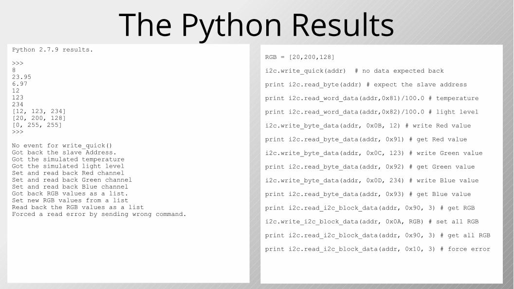
The Python ResultsPython 2.7.9 results.
>>> 823.956.9712123234[12, 123, 234][20, 200, 128][0, 255, 255]>>>
No event for write_quick()Got back the slave Address.Got the simulated temperatureGot the simulated light levelSet and read back Red channelSet and read back Green channelSet and read back Blue channelGot back RGB values as a list.Set new RGB values from a listRead back the RGB values as a listForced a read error by sending wrong command.
RGB = [20,200,128]
i2c.write_quick(addr) # no data expected back print i2c.read_byte(addr) # expect the slave address print i2c.read_word_data(addr,0x81)/100.0 # temperature print i2c.read_word_data(addr,0x82)/100.0 # light level i2c.write_byte_data(addr, 0x0B, 12) # write Red value print i2c.read_byte_data(addr, 0x91) # get Red value i2c.write_byte_data(addr, 0x0C, 123) # write Green value print i2c.read_byte_data(addr, 0x92) # get Green value i2c.write_byte_data(addr, 0x0D, 234) # write Blue value print i2c.read_byte_data(addr, 0x93) # get Blue value print i2c.read_i2c_block_data(addr, 0x90, 3) # get RGB i2c.write_i2c_block_data(addr, 0x0A, RGB) # set all RGB print i2c.read_i2c_block_data(addr, 0x90, 3) # get all RGB print i2c.read_i2c_block_data(addr, 0x10, 3) # force error
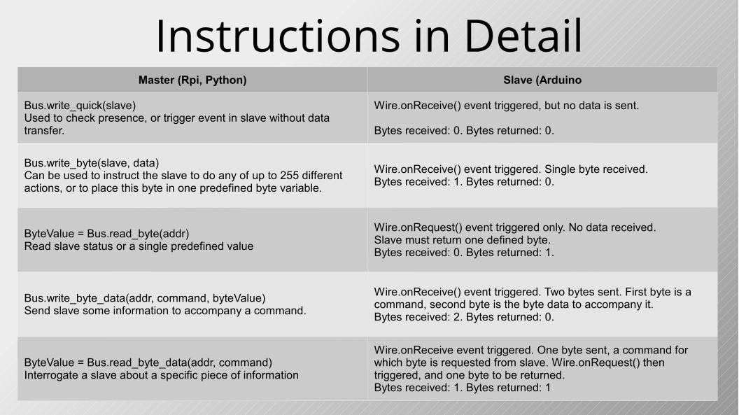
Instructions in DetailMaster (Rpi, Python) Slave (Arduino
Bus.write_quick(slave)Used to check presence, or trigger event in slave without data transfer.
Wire.onReceive() event triggered, but no data is sent.
Bytes received: 0. Bytes returned: 0.
Bus.write_byte(slave, data)Can be used to instruct the slave to do any of up to 255 different actions, or to place this byte in one predefined byte variable.
Wire.onReceive() event triggered. Single byte received.Bytes received: 1. Bytes returned: 0.
ByteValue = Bus.read_byte(addr)Read slave status or a single predefined value
Wire.onRequest() event triggered only. No data received.Slave must return one defined byte.Bytes received: 0. Bytes returned: 1.
Bus.write_byte_data(addr, command, byteValue)Send slave some information to accompany a command.
Wire.onReceive() event triggered. Two bytes sent. First byte is a command, second byte is the byte data to accompany it.Bytes received: 2. Bytes returned: 0.
ByteValue = Bus.read_byte_data(addr, command)Interrogate a slave about a specific piece of information
Wire.onReceive event triggered. One byte sent, a command for which byte is requested from slave. Wire.onRequest() then triggered, and one byte to be returned.Bytes received: 1. Bytes returned: 1
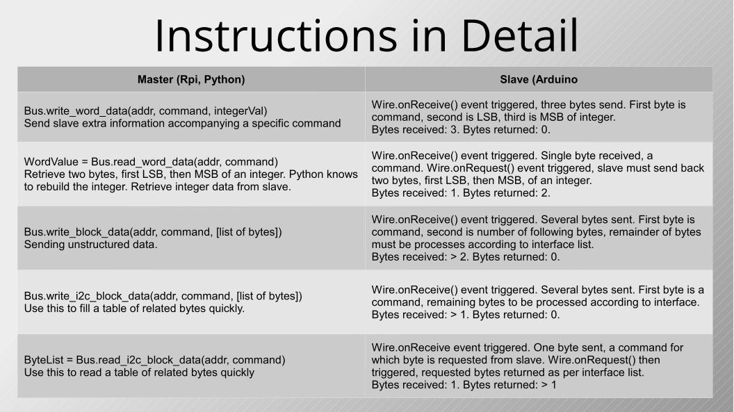
Instructions in DetailMaster (Rpi, Python) Slave (Arduino
Bus.write_word_data(addr, command, integerVal)Send slave extra information accompanying a specific command
Wire.onReceive() event triggered, three bytes send. First byte is command, second is LSB, third is MSB of integer.Bytes received: 3. Bytes returned: 0.
WordValue = Bus.read_word_data(addr, command)Retrieve two bytes, first LSB, then MSB of an integer. Python knows to rebuild the integer. Retrieve integer data from slave.
Wire.onReceive() event triggered. Single byte received, a command. Wire.onRequest() event triggered, slave must send back two bytes, first LSB, then MSB, of an integer.Bytes received: 1. Bytes returned: 2.
Bus.write_block_data(addr, command, [list of bytes])Sending unstructured data.
Wire.onReceive() event triggered. Several bytes sent. First byte is command, second is number of following bytes, remainder of bytes must be processes according to interface list.Bytes received: > 2. Bytes returned: 0.
Bus.write_i2c_block_data(addr, command, [list of bytes])Use this to fill a table of related bytes quickly.
Wire.onReceive() event triggered. Several bytes sent. First byte is a command, remaining bytes to be processed according to interface.Bytes received: > 1. Bytes returned: 0.
ByteList = Bus.read_i2c_block_data(addr, command)Use this to read a table of related bytes quickly
Wire.onReceive event triggered. One byte sent, a command for which byte is requested from slave. Wire.onRequest() then triggered, requested bytes returned as per interface list.Bytes received: 1. Bytes returned: > 1
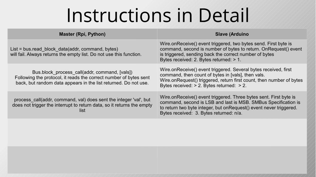
Instructions in DetailMaster (Rpi, Python) Slave (Arduino
List = bus.read_block_data(addr, command, bytes)will fail. Always returns the empty list. Do not use this function.
Wire.onReceive() event triggered, two bytes send. First byte is command, second is number of bytes to return. OnRequest() event is triggered, sending back the correct number of bytesBytes received: 2. Bytes returned: > 1.
Bus.block_process_call(addr, command, [vals])Following the protocol, it reads the correct number of bytes sent back, but random data appears in the list returned. Do not use.
Wire.onReceive() event triggered. Several bytes received, first command, then count of bytes in [vals], then vals.Wire.onRequest() triggered, return first count, then number of bytesBytes received: > 2. Bytes returned: > 2.
process_call(addr, command, val) does sent the integer 'val', but does not trigger the interrupt to return data, so it returns the empty
list
Wire.onReceive() event triggered. Three bytes sent. First byte is command, second is LSB and last is MSB. SMBus Specification is to return two byte integer, but onRequest() event never triggered.Bytes received: 3. Bytes returned: n/a.
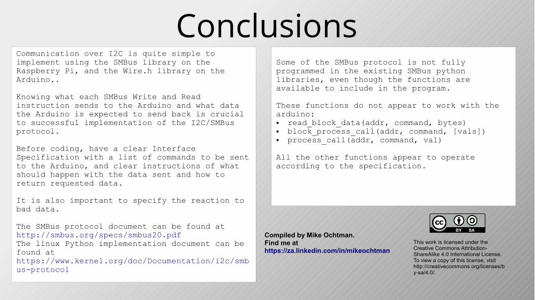
ConclusionsCommunication over I2C is quite simple to implement using the SMBus library on the Raspberry Pi, and the Wire.h library on the Arduino..
Knowing what each SMBus Write and Read instruction sends to the Arduino and what data the Arduino is expected to send back is crucial to successful implementation of the I2C/SMBus protocol.
Before coding, have a clear Interface Specification with a list of commands to be sent to the Arduino, and clear instructions of what should happen with the data sent and how to return requested data.
It is also important to specify the reaction to bad data.
The SMBus protocol document can be found at http://smbus.org/specs/smbus20.pdf The linux Python implementation document can be found at https://www.kernel.org/doc/Documentation/i2c/smbus-protocol
Some of the SMBus protocol is not fully programmed in the existing SMBus python libraries, even though the functions are available to include in the program.
These functions do not appear to work with the arduino: ● read_block_data(addr, command, bytes)● block_process_call(addr, command, [vals])● process_call(addr, command, val) All the other functions appear to operate according to the specification.
This work is licensed under the Creative Commons Attribution-ShareAlike 4.0 International License. To view a copy of this license, visit http://creativecommons.org/licenses/by-sa/4.0/.
Compiled by Mike Ochtman.Find me at https://za.linkedin.com/in/mikeochtman