I11111 111111ll111 Ill11 Ill11 IIIII IIIII Ill11 Ill11 ...I11111 111111ll111 Ill11 Ill11 IIIII IIIII...
15
I11111 111111 l l 111 I l l 11 I l l 11 IIIII IIIII I l l 11 I l l 11 IIIII 11111 11 l l 11111111111111 US006100976A United States Patent [19] [ill Patent Number: 6,100,976 Ackerson [45] Date of Patent: Aug. 8,2000 METHOD AND APPARATUS FOR FIBER OPTIC MULTIPLE SCATTERING SUPPRESSION Inventor: Bruce J. Ackerson, Stillwater, Okla. Assignee: The Board of Regents for Oklahoma State University, Stillwater, Okla. Appl. No.: 091157,733 Filed: Sep. 21, 1998 Related U.S. Application Data Provisional application No. 601059,619, Sep. 23, 1997. Int. Cl? ..................................................... GOlN 15/02 U.S. C1. ........................... 3561336; 3561338; 3561343 Field of Search ..................................... 3561335, 336, 3561338, 322, 341; GOlN 15/02 References Cited 4,676,641 4,854,705 5,090,808 5,155,549 5,396,333 5,502,561 5,513,004 5,621,523 U.S. PATENT DOCUMENTS 611987 Bott ......................................... 3561336 811989 Bachalo .................................. 3561336 211992 Ishikawa et al. ....................... 3561336 311995 Aleshin et al. . 311996 Hutchins et al. . 411996 Naqwi et al. . 411997 Oobayashi et al. . OTHER PUBLICATIONS 1011992 Dhadwal . Nobbmann et al, Multiple-scattering suppression: cross correlation with tilted single mode fibers, Applied Optics, vo1.36, No. 30, Oct. 1997. Ackerson, B.J., R.L. Dougherty, N.M. Reguigui, and U. Nobbmann: “Correlation Transfer: Application of Radiative Transfer Solution Methods to Photon Correlation Prob- lems”, Journal of Thermophysics and Heat Transfer, vol. 6, No. 4, 0ct.-Dec. 1992, pp. 577-588. Brown, R.G.W.: “Dynamic light scattering using monomode optical fibers”, Applied Optics, vol. 26, Nov. 15, 1987, pp. __ 4846-485 1. 16.. INDEX MATCHING VAl - R Fl-IE LENS e 14 Dhont, J.K.G. and C.G. de Kruif “Scattered light intensity cross correlation. I. Theory”, J. Chem. Phys., vol. 79, No. 4, Durian, D.J., D.A. Weitz, and D.J. Pine; “Multiple Light- Scattering Probes of Foam Structure and Dynamics”, Sci- ence, vol. 252, May 1991, pp. 686-688. Lock, James A,: “Role of multiple scattering in cross-cor- related light scattering with a single laser beam”, Applied Optics, vol. 36, No. 30, Oct. 20, 1997, pp. 7559-7570. Mandel, L. and E. Wolf. Optical coherence and quantum optics. Cambridge University Press, pp.188-193, 428-429. Meyer, W.V., D.S. Cannell, A.E. Smart, T.W. Taylor and P. Tin: “Multiple-scattering suppression by cross correlation”, Applied Optics, vol. 36, No. 30, Oct. 20, 1997, pp. Phillies, G.D.J.: “Suppression of multiple scattering effects in quasielastic light scattering by homodyne cross-correla- tion techniques”, J. Chem. Phys., vol. 74, No. 1, Jan. 1, AUg. 15, 1983, pp. 1658-1663. 7551-7570. 1981, pp. 260-262. (List continued on next page.) Primary Examinerqobert H. Kim Assistant ExaminerAayla Lauchman Attorney, Agent, or Firmqellers, Snider, Blankenship, Bailey & Tippens, P.C. [571 ABSTRACT The instant invention provides a method and apparatus for use in laser induced dynamic light scattering which attenu- ates the multiple scattering component in favor of the single scattering component. The preferred apparatus utilizes two light detectors that are spatially and/or angularly separated and which simultaneously record the speckle pattern from a single sample. The recorded patterns from the two detectors are then cross correlated in time to produce one point on a composite singleimultiple scattering function curve. By col- lecting and analyzing cross correlation measurements that have been taken at a plurality of different spatialiangular positions, the signal representative of single scattering may be differentiated from the signal representative of multiple scattering, and a near optimum detector separation angle for use in taking future measurements may be determined. 18 Claims, 4 Drawing Sheets 20 - , ‘41 I I GRIN LENS https://ntrs.nasa.gov/search.jsp?R=20080004059 2020-06-16T22:04:05+00:00Z
Transcript of I11111 111111ll111 Ill11 Ill11 IIIII IIIII Ill11 Ill11 ...I11111 111111ll111 Ill11 Ill11 IIIII IIIII...

I11111 111111ll111 Ill11 Ill11 IIIII IIIII Ill11 Ill11 IIIII 11111 11ll11111111111111 US006100976A
United States Patent [19] [ i l l Patent Number: 6,100,976 Ackerson [45] Date of Patent: Aug. 8,2000
METHOD AND APPARATUS FOR FIBER OPTIC MULTIPLE SCATTERING SUPPRESSION
Inventor: Bruce J. Ackerson, Stillwater, Okla.
Assignee: The Board of Regents for Oklahoma State University, Stillwater, Okla.
Appl. No.: 091157,733
Filed: Sep. 21, 1998
Related U.S. Application Data Provisional application No. 601059,619, Sep. 23, 1997.
Int. Cl? ..................................................... GOlN 15/02 U.S. C1. ........................... 3561336; 3561338; 3561343 Field of Search ..................................... 3561335, 336,
3561338, 322, 341; GOlN 15/02
References Cited
4,676,641 4,854,705 5,090,808 5,155,549 5,396,333 5,502,561 5,513,004 5,621,523
U.S. PATENT DOCUMENTS
611987 Bott ......................................... 3561336 811989 Bachalo .................................. 3561336 211992 Ishikawa et al. ....................... 3561336
311995 Aleshin et al. . 311996 Hutchins et al. . 411996 Naqwi et al. . 411997 Oobayashi et al. .
OTHER PUBLICATIONS
1011992 Dhadwal .
Nobbmann et al, Multiple-scattering suppression: cross correlation with tilted single mode fibers, Applied Optics, vo1.36, No. 30, Oct. 1997. Ackerson, B.J., R.L. Dougherty, N.M. Reguigui, and U. Nobbmann: “Correlation Transfer: Application of Radiative Transfer Solution Methods to Photon Correlation Prob- lems”, Journal of Thermophysics and Heat Transfer, vol. 6, No. 4, 0ct.-Dec. 1992, pp. 577-588. Brown, R.G.W.: “Dynamic light scattering using monomode optical fibers”, Applied Optics, vol. 26, Nov. 15, 1987, pp. _ _ 4846-485 1.
16..
INDEX MATCHING VAl -R
Fl-IE
LENS e 14
Dhont, J.K.G. and C.G. de Kruif “Scattered light intensity cross correlation. I. Theory”, J . Chem. Phys., vol. 79, No. 4,
Durian, D.J., D.A. Weitz, and D.J. Pine; “Multiple Light- Scattering Probes of Foam Structure and Dynamics”, Sci- ence, vol. 252, May 1991, pp. 686-688. Lock, James A,: “Role of multiple scattering in cross-cor- related light scattering with a single laser beam”, Applied Optics, vol. 36, No. 30, Oct. 20, 1997, pp. 7559-7570. Mandel, L. and E. Wolf. Optical coherence and quantum optics. Cambridge University Press, pp.188-193, 428-429. Meyer, W.V., D.S. Cannell, A.E. Smart, T.W. Taylor and P. Tin: “Multiple-scattering suppression by cross correlation”, Applied Optics, vol. 36, No. 30, Oct. 20, 1997, pp.
Phillies, G.D.J.: “Suppression of multiple scattering effects in quasielastic light scattering by homodyne cross-correla- tion techniques”, J . Chem. Phys., vol. 74, No. 1, Jan. 1,
AUg. 15, 1983, pp. 1658-1663.
7551-7570.
1981, pp. 260-262.
(List continued on next page.)
Primary Examinerqobert H. Kim Assistant ExaminerAayla Lauchman Attorney, Agent, or Firmqel le rs , Snider, Blankenship, Bailey & Tippens, P.C.
[571 ABSTRACT
The instant invention provides a method and apparatus for use in laser induced dynamic light scattering which attenu- ates the multiple scattering component in favor of the single scattering component. The preferred apparatus utilizes two light detectors that are spatially and/or angularly separated and which simultaneously record the speckle pattern from a single sample. The recorded patterns from the two detectors are then cross correlated in time to produce one point on a composite singleimultiple scattering function curve. By col- lecting and analyzing cross correlation measurements that have been taken at a plurality of different spatialiangular positions, the signal representative of single scattering may be differentiated from the signal representative of multiple scattering, and a near optimum detector separation angle for use in taking future measurements may be determined.
18 Claims, 4 Drawing Sheets
20
- , ‘41 I I GRIN LENS
https://ntrs.nasa.gov/search.jsp?R=20080004059 2020-06-16T22:04:05+00:00Z

6,100,976 Page 2
OTHER PUBLICATIONS
Phillies, G.D.J.: “Experimental demonstration of mul- tiple-scattering suppression in quasielastic-light-scattering spectroscopy by homodyne coincidence techniques”, Physi- cal Review, vol. 24, No. 4, Oct. 1981, pp. 1939-1943.
RiCka, J.: Dynamic light scattering with single-mode and multimode receivers, Applied Optics, vol. 32, No. 15, May
Segrb, P.N., W. Van Megen, P.N. Pusey, K. Schatzel and W. Peters: “Twosolour dynamic light scattering”, Journal of Modern Optics, vol. 42, No. 9, 1995, pp. 1929-1952.
20, 1993, pp. 2860-2875.
Stieber, F. and W. Richtering: “Fiber-Optic-Dynami- c-Light-Scattering and Two-Color-Cross-Correlation Studies of Turbid, Concentrated, Sterically Stabilized Poly- styrene Latex”, Langmuir, vol. 11, No. 12, 1995, pp. 47244727. Weitz, D.A. and D.J. Pine: “Diffusing-wave spectroscopy”, Dynamic Light Scattering, pp. 652-720. Wiese H. and D. Horn: “Single-mode fibers in fiber-ptic quasielastic light scattering: A study of the dynamics of concentrated latex dispersions”, J. Chem., Phys., vol. 94, No. 10, May 15, 1991, pp. 6429-6443. Berne, B.J., and R. Pecora; Dynamic Light Scattering, Wiley, New York, 1976, pp. 1-90.
U S . Patent Aug. 8,2000 Sheet 1 of 4 6,100,976
U S . Patent Aug. 8,2000 Sheet 2 of 4 6,100,976
U S . Patent Aug. 8,2000
0 1
x
Sheet 3 of 4
h! 2 8 B N >-
6,100,976
U S . Patent Aug. 8,2000 Sheet 4 of 4 6,100,976
r: 0
N 8
5 * I o
0 (0
0 7
0 0 0 u) d e3 cv 0
[ UIU] m a w
6,100,976 1 2
METHOD AND APPARATUS FOR FIBER OPTIC MULTIPLE SCATTERING
SUPPRESSION
RELATED APPLICATIONS
tiple scattering sample. One such scheme is a fiber semi- backscattering technique that utilizes scattered photons from a small overlap region between an input and a detecting fiber [5]. In this approach, most of the scattering paths within the
s sample volume involve only single collisions with particles. However, this method does not yield a systematic way of determining the degree of single scattering for different samples. Additionally, in some cases the solution, or the
i o (because the fiber may need to be inserted into the sample
This application claims the benefit of U.S. Provisional Application No. 601059,619, which application was filed
disclosure of which is incorporated herein by reference. with the Patent and Trademark Office On Sep' 23, 1997, the particles present therein, can coat the detecting fiber
STATEMENT REGARDING FEDERALLY SPONSORED RESEARCH
during measurement), thereby corrupting the received sig- nal.
The other approach focuses on multiple scattering elimi- nation by cross correlating the signal of two different inti-
NASA and Grant 15 dent wave lengths at the same scattered wave vector for each [6, 71 and is based on the multiple scattering elimination methods of Phillies [S, 9,101. Two-Color-Cross-Correlation detects only true single scattering. A drawback of this technique is that it requires extensive careful alignment of
20 two input laser beams and two detectors. Additionally, the turbidity of the sample must be small enough to still exhibit significant single scattering. Thus, the technique is limited to small scattering concentrations that can be increased slightly by reducing the sample dimensions.
It is accordingly an object of the present invention to
It is a related object to provide an efficient means of suppressing the multiple scattering contribution from an illuminated turbid media so that true single scattering data
It is another object that the invention be cost effective from an equipment requirement standpoint, utilizing a single laser input beam and readily available component parts.
Before proceeding to a description of the instant invention, however, it should be noted and remembered that the description of the invention which fo~~ows, together with the accompanying drawings, should not be construed as limiting the invention to the examples (or preferred
Dynamic light scattering exploits the time dependent 4o embodiments) shown and described. This is so because those skilled in the art to which the invention pertains will be able to devise other forms of this invention within the ambit of the appended claims.
This invention was made with Government support under
NSF. The Government contract Number NAG3-1624 awarded Number DMR-9501865 awarded has certain rights in this invention.
BACKGROUND OF THE INVENTION
FIELD OF THE INVENTION
This invention relates generally to determining the physi- cal properties of materials through the use of dynamic light scattering, and, more specifically, to a technique for detect- ing and evaluating singly scattered speckle in concentrated 25 solutions by suppressing the multiply scattered contribution. analyze the single scattering of light in turbid media,
BACKGROUND
When light impinges on matter, a portion of that light is scattered or reflected away. The frequency shifts, the angular 30 may be obtained and evaluated. distribution, the polarization, and the intensity of the scat- tered light are determined by the size, shape, and molecular interactions of the particles in the scattering material. Thus, from the light-scattering characteristics of a given system it 35
is possible, with the aid of electrodynamics and the theory of time-dependent statistical mechanics, to obtain informa- tion about the structure and molecular dynamics of the scattering medium.
coherence loss of scattered light to explore the movement of the scatterers. Its applications range from measurements of molecules or particles smaller than the wavelength of the probing light [l] to the much larger structures of, for example, foam [2]. Small scatterers are easily analyzed through the single scattering of photons. Single scattering occurs when each molecule or particle is exposed to essen- tially the same incident light as occurs in relatively dilute solutions.
Diffusing Wave Spectroscopy [3] and Correlation Trans- fer Theory [4] make the investigation of more concentrated colloidal samples possible. Both theories, however, presume a knowledge of the single scattering correlation function. This function is often unknown in practical multiple scat-
..
SUMMARY OF THE INVENTION 4s
Broadly speaking, the instant invention provides a method and apparatus for estimating single scattering functions - particularly in concentrated solutions. The instant method utilizes two light detectors that are spatially and/or angularly
50 separated and which simultaneously record the speckle pattern from a single sample. The recorded patterns from the two detectors are then cross correlated at zero-lag to produce one point on a composite singleimultiple scattering function (SIN) curve. By collecting and analyzing cross correlation
tering applications, where the incident light may not equally 5s measurements that have been taken at a plurality of different expose all particles or where certain particles may be spatialiangular positions, the signal representative of single exposed to light scattered by other particles. Further, even scattering may be differentiated from the signal representa- though an equivalent single scattering decay time can be tive of multiple scattering, and a near optimum detector obtained by using the transmitted intensity relative to a angle for use in taking future measurements may be deter- known optical thickness reference, where the standard func- 60 mined. tional form for the single scattering correlation function as By way of general background, when a laser beam is an exponential is known, the form of the mean square directed into a scattering medium and reflects from a surface displacement must still be assumed. It would therefore be a speckle pattern is often observed, This complex pattern very useful to measure the single scattering contribution results from interference of electromagnetic radiation which inside a multiple scattering sample. 65 originated from a coherent source but which has followed
Heretofore, two different schemes have been available for different paths in reflecting or scattering to the detector. At extracting some single scattering information from a mul- some points, the total field reflecting from the surface will
6,100,976 3
add constructively and be bright, while at other points the total field will add destructively and be dark. If the laser beam is focused to a small region on the reflecting surface, the speckle size typically increases in dimension at the detector. This diffraction effect is analogous to that observed in single slit diffraction, where the diffraction pattern width increases as the slit width decreases. Further, the single scattered light, arising as it does within the laser beam, will tend to originate from a smaller region than the multiple scattered light which tends to be diffused throughout the sample. For this reason, at the detector the single scattered light will have a broad speckle field compared to the multiple scattered speckle.
Turning now to a discussion of various aspects of the instant invention, according to one preferred embodiment there is provided a method, whereby it is possible to identify and separate the contribution of the multiple scattered light from the single scattered light based on the properties of the respective speckles. Since the single scattering speckle (which arises from inside of the incident laser beam) is correlated over a wider angular or spatial range than is the multiple scattering speckle (which might potentially origi- nate from anywhere within the sample), by using two detectors with an appropriately selected spatial (or angular) separation, it is possible to detect the single scattered speckle and attenuate or exclude the multiple scattered speckle contribution. At each angular setting, the light intensities received within the two detectors are cross correlated in time to produce a single numerical value for that detector angle. By collecting cross correlations at a number of different detector angles, a profile is created that can be used to determine the angular ranges over which multiple and single scattering predominate. From the individual cross correla- tions and the ensemble of angle and cross correlation pairs, it is additionally possible to estimate the optimum (or near optimum) detector angle to use in collecting future observations, as well as a variety of other useful quantities that pertain to the particles of the laser-illuminated sample.
A preferred apparatus for use with the instant invention suppresses multiple light scattering by using two slightly- tilted detectors that are directed toward the same sample volume which has been illuminated by a narrow laser beam. Further, a mechanism is provided whereby the angle between the two detectors may be continuously adjusted so as to give readings at any selected separating angle. The apparatus further preferably utilizes single-mode fiber optic fibers as detectors, single mode fibers being almost ideal for use in detecting dynamic light scattering in dilute suspen- sions. Additionally, optical fiber GRIN (i.e., graded index) lenses are preferably used on the ends of the monomode fibers to improve the performance of the invention.
As another preferred embodiment of the instant invention, there is provided an apparatus substantially as described above, but wherein a polarizing filter is placed between the sample and the detectors. In the preferred embodiment, the polarizing filter is placed in one of two orientations with respect to the incident laser beam’s polarization plane: it is either oriented to have the same polarization (parallel) or or ien ted to have a perpendicular po lar iza t ion (perpendicular). Although both polarization components show multiple scattering contributions, only the parallel component contains evidence of the single scattering signal. Thus, the orientation of the polarizer may be used as part of a preferred embodiment to increase the signal-to-noise ratio and eliminate some of the multiple scattering in the received signal.
According to still another preferred embodiment, the collected ensemble of angleicross correlation pairs can be
4 used with numerical curve fitting routines to provide an estimate of, by way of example, a two-cumulant represen- tation of the time decay of the intensity correlation function and, thus, an estimate of the particle size. When applied to
s the polarization embodiment of the instant invention, the curve fitting results for the two polarization components support the theory which calls for larger single scattering speckles in the parallel component, and smaller multiple scattering speckles in both the parallel and perpendicular
Finally, in another preferred embodiment the methods described previously are extended to much higher concen- trations by detecting the scattering from particles close to the sample boundaries. When the instant apparatus detects the
1s particles close to the boundaries of the sample container, there is no limit on the applicable optical thickness except for the exponential decay of intensity. There are always some multiple scattering contributions present that lead to some non-exponentiality. The main decay, though, is sur-
20 prisingly accurate and can be used to measure the particle sizes of concentrated samples with ease.
Abetter understanding of the present invention, its several aspects, and its objects and advantages will become apparent to those skilled in the art from the following detailed
2s description, taken in conjunction with the attached drawings, wherein there is shown and described the preferred embodi- ment of the invention, simply by way of illustration of the best mode contemplated for carrying out the invention.
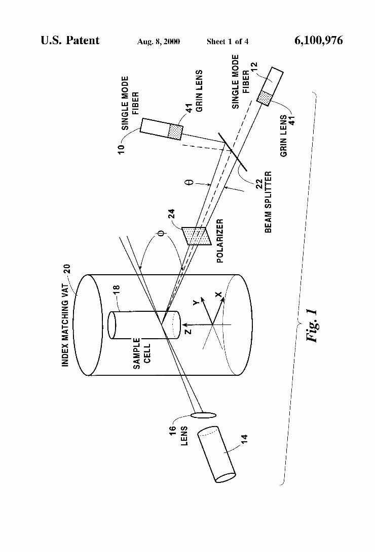
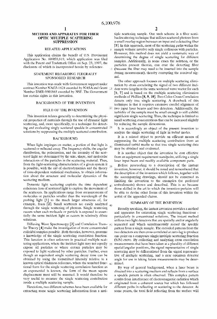
BRIEF DESCRIPTION OF THE DRAWINGS FIG. 1 is a diagram of an experimental setup for the
preferred fiber optic multiple scattering suppression tech- nique.
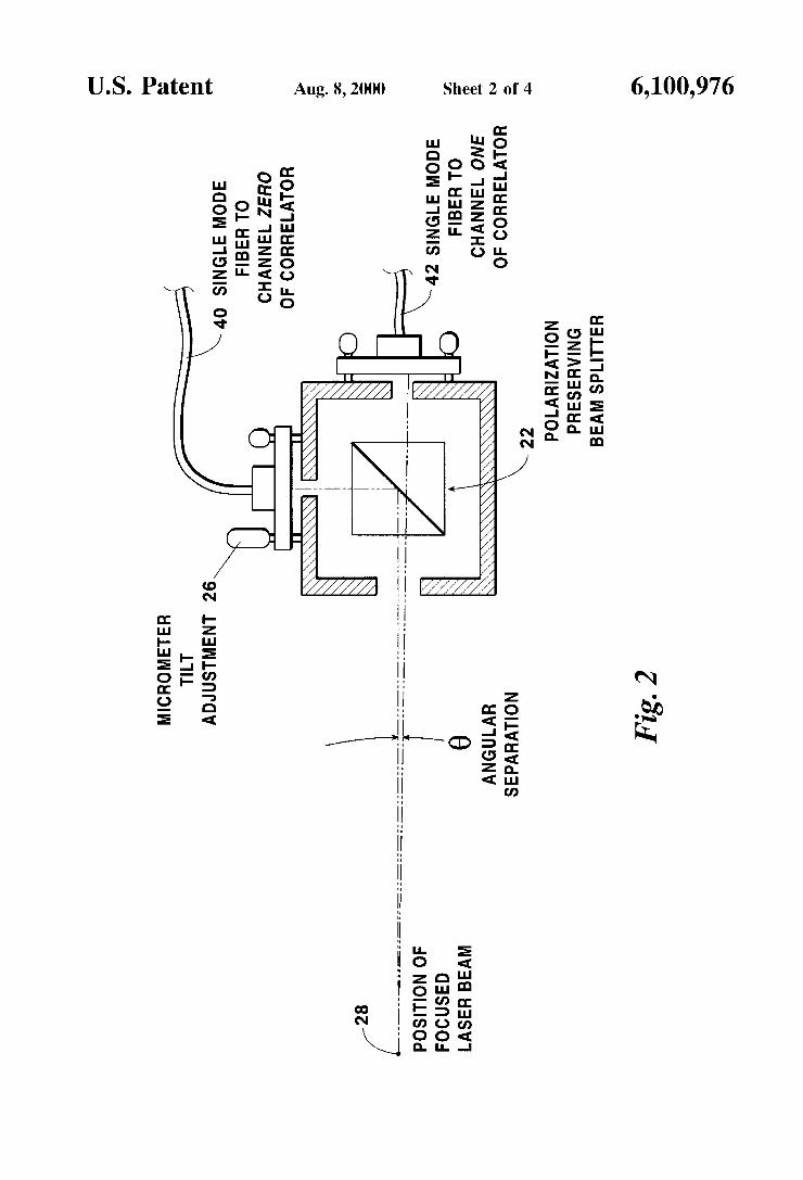
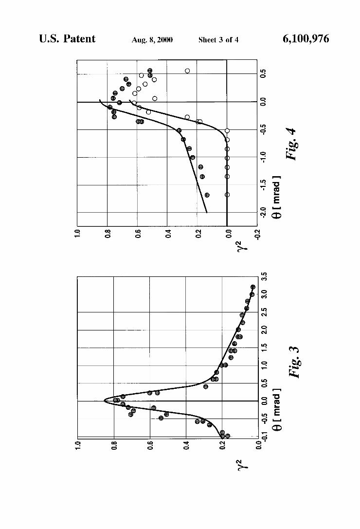
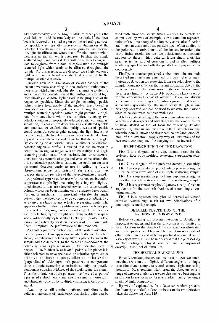
FIG. 2 is a diagram of the preferred detecting assembly. FIG. 3 is a representative plot of intercept versus angular
tilt for the cross correlation of a multiple scattering sample. FIG. 4 is a representative plot of intercept versus angular
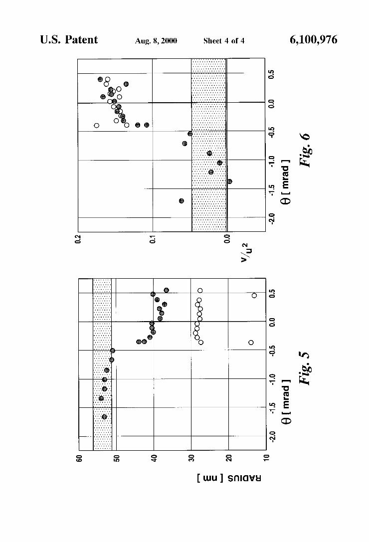
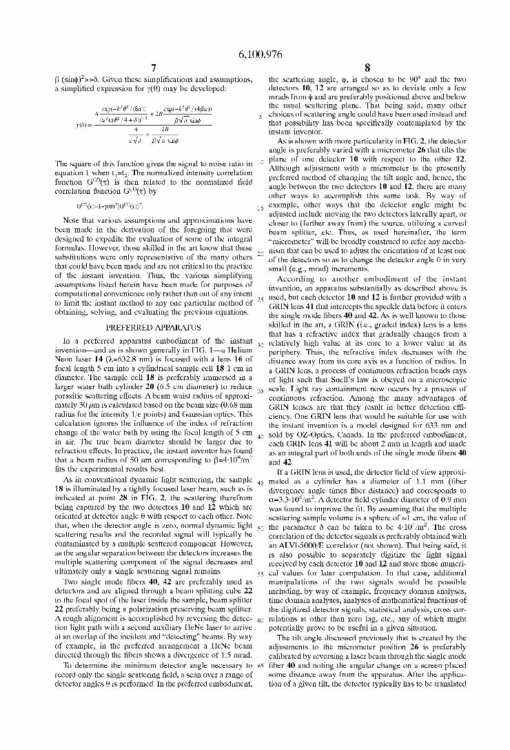
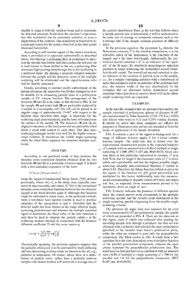
tilt for the two polarizations of a multiple scattering sample. FIG. 5 is a representative plot of particle size (nm) versus
40 angular tilt for the two polarizations of a non-single scat- tering sample.
FIG. 6 is a representative plot of normalized second cumulant versus angular tilt for two polarizations of a non-single scattering sample.
DETAILED DESCRIPTION OF THE PREFERRED EMBODIMENT
Before explaining the present invention in detail, it is important to understand that the invention is not limited in
50 its application to the details of the construction illustrated and the steps described herein. The invention is capable of other embodiments and of being practiced or carried out in a variety of ways. It is to be understood that the phraseology and terminology employed herein are for the purpose of
THEORETICAL BACKGROUND Broadly speaking, the instant invention utilizes two detec-
tors that are aimed at slightly different angles at a single 60 laser-illuminated sample to record scattered light emanating
therefrom. Measurements taken from the detectors over a range of detector angles are used to determine a best angular separation to use so as to observe predominantly the single scattered light component.
By way of explanation, for a Gaussian random process, the intensity correlation function between the two detectors takes the following form [15]:
i o components.
30
35
4s
5s description and not of limitation.
65

5 6,100,976
6 - - - - - - <I( r l,tl)~( r z,tz)>=<~( r l,tl)><~( r z , tz )>[~+~y( r 1, r z,tl-tz)l~~. (I) The beam splitter 22 was used for purposes of convenience
only, and it is not a requirement of the instant invention that the detectors 10 and 12 be so oriented. The net effect, In this equation, the function ye) is the second order
complex degree of coherence, and I ( I , t) is the light
intensity at the point ((<.>”) indicates that a tirne average or expected value is to be taken of the argument (or an ensemble average for a stationary process). In typical dynamic light scattering applications, there is a single detector ( r 1= r 2) and the time dependence of the (auto) correlation function carries
purposes of the instant invention is the signal-to-noise ratio or the complex degree of coherence when t,=t,, for a similar signal measured by two detectors oriented at slightly differ-
scattering volume are spatially uncorrelated, then the van Cittert-Zernike theorem in the far field limit gives [16]:
however, is to obtain signals from the detectors that are at time t, The bracket notation (i,e,, 5 comparable to those that would have been obtained if the
detectors had both been directly aimed at the sample 18. Finally, in the text that follows the detectors will be spoken of as though they are both Pointed directly toward the sample 18, but those skilled in the art will understand that
IO mirrors, beam splitters, etc. make it possible to position the
The input laser 14 is preferably positioned in the xy-plane at an angle 4 (the “traditional” scattering angle) with respect to the x-axis. For 4=90 degrees, the incident beam is thus
angle 4, i.e., theta is the angular separation of the unit
vectors s and s 2, which unit vectors lie in the x-z plane. Because 4, which is usually about 1 radian, is typically
much larger than 8, which is preferably measured in milli- 2o radians, the magnitude of the scattering wave vector is well
approximated by the standard expression:
+
+ +
the desired information, However, of particular interest for detectors lo and l2 in any arbitrary Orientation.
ent angles, If intensities originating at different regions in the parallel to the y-axis, and the x-axis preferably bisects the
+ +
p ) e x p [ - i + l -;z) .:1d3~1 Y ( & , k 0 ) =
S/(i‘)d3 r‘
q=4nn sin(@/Z)/h, In the previous equation, k=2xn/h is the wave vector of
the elastically scattered radiation having wavelength h in the 25 where “n” is the refractive index of the fluid suspension. The field of view of detector 10 is, thus, approximated by the
medium with refractive index n. The unit vectors s and following “gaussian tube,,: s point from an origin in the scattering volume to the two
been extended from a two dimensional surface integral to a 30 three dimensional volume integral to accommodate scat- tered light coming from a three dimensional volume. The
light intensity I( r ‘)is determined by the overlap of the
volume, and the field of view of the detectors. Aphase factor
no contribution to Iy( r 1,r2,0)12, the quantity measured in the preferred embodiment of the instant invention.
+
+
detector positions. Note that the previous integration has Il(x,y,z)=exp(-a(y’+(z cos (e/z)-x sin (ei2))’)).
Here 1 / 6 is the radius of the l ie point for the intensity if the field of view is uniformly illuminated. The field of view for detector 12 is similarly approximated by: +
incident beam, the multiple scattering within the sample 35
has been ignored in the above expression because it makes
IZ(x,y,z)=exp(-a(y’+(z cos(8/2)+x sin(ei2))’)).
The incident beam intensity is approximated by +
I~~(x,y,z)=Bexp(-B(z’+(x sin(@)+y cos(@))’)),
FIG. 1 shows a preferred two-detector scattering geom- 40 where the maximum intensity on-axis is given by the etry for use with the instant invention, wherein the scattering angle 4 has been selected to be about equal to ninety degrees
parameter “B”. The multiple scattered intensity is assumed to be uniformly distributed with magnitude “A” and it is
and the incident beam lies in the xy plane, Note that the further assumed to be incoherent with respect to the incident geometry illustrated in that figure-including the choice of beam at the Same location. This simply means that the a particular value for the parameter +is just one of many 45 incident and multiple scattered intensities are added that could be used and it is well within the ability of those together, rather than adding their field amplitudes and squar- skilled in the art to devise other arrangements, The two ing the result. Finally, the finite size of the sample 18 is detectors 10, 12 in FIG. 1 are preferably oriented in the represented by a Gaussian cutoff function: xz-plane and each forms an (extremely) small (e.g., mrad) angle 812 with respect to the x-axis. That being said, it is not SO essential to the operation of the instant invention that the detectors be oriented in any particular plane nor set at any particular scattering angle 4. It is anticipated, though, that generally the detectors and sample detection volume will be aligned in a plane which contains a direction that is perpen- ss d F 1 ? h r O ) =
dicular to the direction of the incident beam. The single
scattered speckle in these directions. It is required, though, that the two detectors 10 and 12 be aimed toward the sample in such a way that they detect substantially the same portion 60 of the scattered field and that the angle between their Assuming a small focused laser beam and an intermediate respective lines-of-sight be very small. detection width and a large sample volume, then the param-
Further note in FIG. 1 that, strictly speaking, the detectors eters 0, a, and 6 will be assumed to have the following 10 and 12 are not both aimed directly at the sample, but relationship: fl>>a>>G. Further, since the angle between the rather a beam splitter 22 allows detector 10 to be aimed in 65 detectors, 8 , is extremely small, the standard substitutions a direction that is roughly transverse to the direction in sin(8)-8 and cos(8)-l may be used. It is also fair to assume which detector 12 is aimed and still detect the scattered field. that $>>e which leads, in turn, to the inequality:
IgC(x,y, z)=exp (-2S(x’+y’+z’)).
Combining these factors together as they occur in the preferred measurement geometry yields:
scattered speckle is elongated to the multiple ~eXP(-E2~Zsin(e!2)d(1-, Y . Z)IZ(x, Y . Z)Igc@ Y . Z)(A + Iss(x3 Y . Z))d3r
~ I I ( x , Y . z)~z(x , Y . Z I I ~ A ~ , Y . z)(A + I&, Y . z))d3r
6,100,976 7 8
fl (sin$)’>>6. Given these simplifications and assumptions, a simplified expression for y(0) may be developed:
exp(-k2B2 / (Su)) exp(-k2B2 / (4pu)) A + 2B
(u2(us2 14 + 6))”2 pv’Fsin4 A 2B m =
The square of this function gives the signal to noise ratio in equation 1 when t,=t,. The normalized intensity correlation function G(’)(.c) is then related to the normalized field correlation function G(’)(.c) by
G(~)(T)=~+~(~)~(G(~)(T))~.
Note that various assumptions and approximations have been made in the derivation of the foregoing that were designed to expedite the evaluation of some of the integral formulas. However, those skilled in the art know that these substitutions were only representative of the many others that could have been made and are not critical to the practice of the instant invention. Thus, the various simplifying assumptions listed herein have been made for purposes of computational convenience only rather than out of any intent to limit the instant method to any one particular method of obtaining, solving, and evaluating the previous equations.
PREFERRED APPARATUS
In a preferred apparatus embodiment of the instant invention-and as is shown generally in FIG. 1-a Helium Neon laser 14 (h=632.8 nm) is focused with a lens 16 of focal length 5 cm into a cylindrical sample cell 18 1 cm in diameter. The sample cell 18 is preferably immersed in a larger water bath cylinder 20 (6.5 cm diameter) to reduce parasitic scattering effects. A beam waist radius of approxi- mately 30pm is calculated based on the beam size (0.68 mm radius for the intensity l ie points) and Gaussian optics. This calculation ignores the influence of the index of refraction change of the water bath by using the focal length of 5 cm in air. The true beam diameter should be larger due to refraction effects. In practice, the instant inventor has found that a beam radius of 50 pm corresponding to fl=4.10s/m2 fits the experimental results best.
As in conventional dynamic light scattering, the sample 18 is illuminated by a tightly focused laser beam, such as is indicated at point 28 in FIG. 2, the scattering therefrom being captured by the two detectors 10 and 12 which are oriented at detector angle 0 with respect to each other. Note that, when the detector angle is zero, normal dynamic light scattering results and the recorded signal will typically be contaminated by a multiple scattered component. However, as the angular separation between the detectors increases the multiple scattering component of the signal decreases and ultimately only a single scattering signal remains.
Two single mode fibers 40, 42 are preferably used as detectors and are aligned through a beam splitting cube 22 to the focal spot of the laser inside the sample, beam splitter 22 preferably being a polarization preserving beam splitter. A rough alignment is accomplished by reversing the detec- tion light path with a second auxiliary HeNe laser to arrive at an overlap of the incident and “detecting” beams. By way of example, in the preferred arrangement a HeNe beam directed through the fibers shows a divergence of 1.5 mrad.
To determine the minimum detector angle necessary to record only the single scattering field, a scan over a range of detector angles 0 is performed. In the preferred embodiment;
the scattering angle, $, is chosen to be 90” and the two detectors 10, 12 are arranged so as to deviate only a few mrads from $ and are preferably positioned above and below the usual scattering plane. That being said, many other
5 choices of scattering angle could have been used instead and that possibility has been specifically contemplated by the instant inventor.
As is shown with more particularity in FIG. 2, the detector angle is preferably varied with a micrometer 26 that tilts the plane of one detector 10 with respect to the other 12. Although adjustment with a micrometer is the presently preferred method of changing the tilt angle and, hence, the angle between the two detectors 10 and 12, there are many other ways to accomplish this same task. By way of example, other ways that the detector angle might be adjusted include moving the two detectors laterally apart, or closer to (farther away from) the source, utilizing a curved beam splitter, etc. Thus, as used hereinafter, the term “micrometer” will be broadly construed to refer any mecha-
2o nism that can be used to adjust the orientation of at least one of the detectors so as to change the detector angle 0 in very small (e.g., mrad) increments.
According to another embodiment of the instant invention, an apparatus substantially as described above is
25 used, but each detector 10 and 12 is further provided with a GRIN lens 41 that intercepts the speckle data before it enters the single mode fibers 40 and 42. As is well known to those skilled in the art, a GRIN (i.e., graded index) lens is a lens that has a refractive index that gradually changes from a
30 relatively high value at its core to a lower value at its periphery. Thus, the refractive index decreases with the distance away from its core axis as a function of radius. In a GRIN lens, a process of continuous refraction bends rays of light such that Snell’s law is obeyed on a microscopic
35 scale. Light ray containment now occurs by a process of continuous refraction. Among the many advantages of GRIN lenses are that they result in better detection effi- ciency. One GRIN lens that would be suitable for use with the instant invention is a model designed for 633 nm and
40 sold by OZ-Optics, Canada. In the preferred embodiment, each GRIN lens 41 will be about 2 mm in length and made as an integral part of both ends of the single mode fibers 40 and 42.
If a GRIN lens is used, the detector field of view approxi- 45 mated as a cylinder has a diameter of 1.1 mm (fiber
divergence angle times fiber distance) and corresponds to a=3.3.106/m2. A detector field cylinder diameter of 0.9 mm was found to improve the fit. By assuming that the multiple scattering sample volume is a sphere of -1 cm, the value of
50 the parameter 6 can be taken to be 4.104/m2. The cross correlation of the detector signals is preferably obtained with an ALV1-5000/E correlator (not shown). That being said, it is also possible to separately digitize the light signal received by each detector 10 and 12 and store those numeri-
5s cal values for later computation. In that case, additional manipulations of the two signals would be possible including, by way of example, frequency domain analyses, time domain analyses, analyses of mathematical functions of the digitized detector signals, statistical analysis, cross cor-
60 relations at other than zero lag, etc., any of which might potentially prove to be useful in a given situation.
The tilt angle discussed previously that is created by the adjustments to the micrometer position 26 is preferably calibrated by reversing a laser beam through the single mode
65 fiber 40 and noting the angular change on a screen placed some distance away from the apparatus. After the applica- tion of a given tilt, the detector typically has to be translated
6,100,976 9
slightly to align it with the incident beam and to maximize the detected intercept. It has been the inventor’s experience that this translation can be extremely sensitive to even a slight touch of the controls. This sensitivity is believed to be a principal reason for the scatter observed in the data points discussed hereinafter.
According to still another aspect of the instant invention, there is provided an to apparatus substantially as described above, but wherein a polarizing filter is positioned to inter- cept the speckle data before that data reaches the detector. As is well known to those skilled in the art, a polarizing filter attenuates light passing therethrough that is not oscillating in a preferred plane. By placing a properly oriented polarizer between the sample and the detectors, some of the multiple scattering will be eliminated and the signal-to-noise ratio will be thereby increased.
Finally, according to another useful embodiment of the instant invention, the apparatus was further arranged so as to be suitable for to measuring particle sizes in a polystyrene sample of 2% volume fraction. The arrangement of the detectors 10 and 12 is the same as that shown in FIG. 1, but the sample 18 and water bath 20 are preferably replaced by a sample in a rectangular cell. The cell can be placed in an angular range of approximately 15-60’ with respect to the incident laser direction (this angle is important for the scattering angle determination), and the laser is focused near the surface of the sample 18. The detectors 10 and 12 are aligned to measure at the focal point and are preferably tilted about 1 mrad with respect to each other. This skin layer scattering technique works very well for the highly concen- trated volumes. It maximizes the visible single scattering while the tilted fibers suppress the attendant multiple scat- tering.
ANALYSIS
According to one preferred mode of data analysis, the intensity cross correlation function obtained from the two detectors 10 and 12 at a particular d etector angle 8’ is fitted with a two-cumulant expansion of the form
G ( Z ) ( ~ ) = l + ~ Z ( B ’ ) e ~ p ( - Z ~ + Z ~ z )
using the signal-to-background fitting factor y’(8’) defined previously, where -c=t,-t, is the delay time, typically mea- sured in microseconds, and where G(’)(.c) is the normalized intensity cross correlation function between the two detector signals at the fixed detector angle 8. Although this function might be estimated in many ways, in the preferred embodi- ment a non-linear least squares routine is used to produce estimates of the parameters u and v. Provided that the detector angle has been chosen in the range wherein single scattering predominates and wherein the multiply scattered signal is attenuated, the fitted value of the first cumulant u may then be used to estimate the particle radius r in the scattering medium through its connection with the Einstein diffusion coefficient D and the wave vector q:
Theoretically speaking, the previous equation requires that the particles whose size is to be estimated be freely diffusing and non-interacting as those terms are known in the art, e.g., particles in suspension. Of course, where there is a distri- bution of particle sizes-rather than a perfectly uniform sample-the instant method will return the z-average size of
10 the particle distribution Thus, in the text that follows when a sample particle size is determined, it will be understood to be some sort of average or composite measure such as the z-average size if the sample contains particles of different
In the previous equation, the parameter k, denotes the Boltzmann constant, T is the absolute temperature, n is the refractive index of the suspension, q the viscosity of the sample and h the laser wavelength. Additionally, the nor-
i o malized second cumulant v/u2 is an indicator of the “qual- ity” of the fit since, for absolutely monodisperse spherical particles in single scattering, the normalized second cumu- lant should vanish. The normalized second cumulant is also an indicator of the variance of particle sizes in the sample,
is i.e., for a sample containing particles with a distribution of sizes, this parameter can be an indicator of the polydispersity (i.e., the relative width of the size distribution). In the examples that are discussed below, normalized second cumulant values less then or equal to about 0.05 in the dilute
s sizes.
20 single scattering limit are expected.
EXAMPLES
In the specific examples that are presented hereinafter, the sample consisted of polystyrene spheres of diameter 0.107
25 pm manufactured by Duke Scientific (5.6% CV, Lot 16203) and diluted with water to 0.15 and 0.25% volume fraction. It should be noted that these examples are offered for purposes of illustration only and are not intended to limit the scope of application of the instant invention.
FIG. 3 contains a plot of the signal-to-background for a range of different detector angles 8 for a lower volume fraction sample. The solid line that is drawn over the experimental measurement points is the expected behavior
35 of a sample with an assumed ratio (AB) of multiple to single scattering of 1:600. (PST 0.107 pm, @=0.0015). Great care was taken in this particular experiment to measure y2 near 8=0. Note that for larger 8 the measured value of y2 is more stable and reproducible and that the highest possible single
4o scattering intensity auto-correlation function y2 occurs at about 0.85. Therefore the fitting function (which is given by the square of the function for y(8) given previously) was multiplied by this factor. Additionally, note that measure- ments corresponding to negative values of 8 were also taken
45 and that, as expected, those measurements proved to by symmetric about an angle of zero.
FIG. 3 clearly indicates the presence of different speckle sizes: the central narrow peak corresponds to the multiple scattering speckle and the broader peak underneath is the
50 single scattering speckle originating from the smaller single scattering volume.
The previous tilt angle scan was repeated for an even more concentrated 0.107 pm polystyrene sample, the results of which are presented in FIG. 4. There are two data sets in
ss this figure, each of which was collected after passing the incoming speckle data through a polarizer: one data set was obtained with a polarizer that selected the same polarization (parallel) as the incident laser beam’s polarization plane, while the other set oriented to pass only the perpendicular
60 component. The filled circles in FIG. 4 result from a two cumulant fit to the time dependent cross correlation function of the parallel polarization component, whereas the open circles represent the perpendicular polarization data. The solid lines on that plot have been calculated with an assumed
65 ratio (AB) of multiple to single scattering of 1:700 for the parallel and 1:0 for the perpendicular component. (PST 0.107 pm, @=0.0025).
30
6,100,976 11
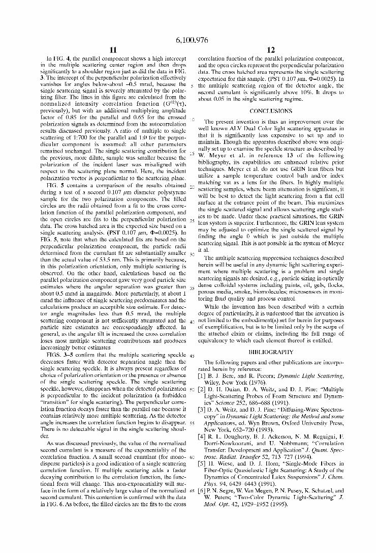
In FIG. 4, the parallel component shows a high intercept in the multiple scattering center region and then drops significantly to a shoulder region just as did the data in FIG. 3. The intercept of the perpendicular polarization effectively vanishes for angles below-about -0.5 mrad, because the single scattering signal is severely attenuated by the polar- izing filter. The lines in this figure are calculated from the normalized intensity correlation function (G(’)(T), previously), but with an additional multiplying amplitude factor of 0.85 for the parallel and 0.65 for the crossed polarization signals as determined from the autocorrelation results discussed previously. A ratio of multiple to single scattering of 1:700 for the parallel and 1:0 for the perpen- dicular component is assumed: all other parameters remained unchanged. The single scattering contribution for the previous, more dilute, sample was smaller because the polarization of the incident laser was misaligned with respect to the scattering plane normal. Here, the incident polarization vector is perpendicular to the scattering plane.
FIG. 5 contains a comparison of the results obtained during a test of a second 0.107 pm diameter polystyrene sample for the two polarization components. The filled circles are the radii obtained from a fit to the cross corre- lation function of the parallel polarization component, and the open circles are fits to the perpendicular polarization data. The cross hatched area is the expected size based on a single scattering analysis. (PST 0.107 pm, @=0.0025). In FIG. 5, note that when the calculated fits are based on the perpendicular polarization component, the particle radii determined from the cumulant fit are substantially smaller than the actual value of 53.5 nm. This is primarily because, in this polarization orientation, only multiple scattering is observed. On the other hand, calculations based on the parallel polarization component gave very good particle size estimates where the angular separation was greater than about 0.5 mrad in magnitude. More particularly, at about 1 mrad the influence of single scattering predominates and the calculations produce an acceptible size estimate. For detec- tor angle magnitudes less than 0.5 mrad, the multiple scattering component is not sufficiently attenuated and the particle size estimates are correspondingly affected. In general, as the angular tilt is increased the cross correlation loses most multiple scattering contributions and produces increasingly better estimates.
FIGS. 3-5 confirm that the multiple scattering speckle decreases faster with detector separation angle then the single scattering speckle. It is always present regardless of choice of polarization orientation or the presence or absence of the single scattering speckle. The single scattering speckle, however, disappears when the detected polarization is perpendicular to the incident polarization (a forbidden “transition” for single scattering). The perpendicular corre- lation function decays faster than the parallel one because it contains relatively more multiple scattering. As the detector angle increases the correlation function begins to disappear. There is no detectable signal in the single scattering shoul- der.
As was discussed previously, the value of the normalized second cumulant is a measure of the exponentiality of the correlation function. A small second cumulant (for mono- disperse particles) is a good indication of a single scattering correlation function. If multiple scattering adds a faster decaying contribution to the correlation function, the func- tional form will change. This non-exponentiality will sur- face in the form of a relatively large value of the normalized second cumulant. This contention is confirmed with the data in FIG. 6. As before, the filled circles are the fits to the cross
12 correlation function of the parallel polarization component, and the open circles represent the perpendicular polarization data. The cross hatched area represents the single scattering expectation for this sample. (PST 0.107 pm, @=0.0025). In
s the multiple scattering region of the detector angle, the second cumulant is significantly above 10%. It drops to about 0.05 in the single scattering regime.
CONCLUSIONS lo The present invention is thus an improvement over the
well known ALV Dual Color light scattering apparatus in that it is significantly less expensive to set up and to maintain. Though the apparatus described above was origi- nally set up to examine the speckle structure as described by W. Meyer et al. in reference 13 of the following bibliography, its capabilities are enhanced relative prior techniques. Meyer et al. do not use GRIN lens fibers but utilize a sample temperature control bath and/or index matching vat as a lens for the fibers. In highly multiple
2o scattering samples, where beam attenuation is significant, it will be best to detect the light scattering from a flat cell surface at the entrance point of the beam. This maximizes the single scattered signal and allows scattering angle stud- ies to be made. Under these practical situations, the GRIN
2s lens system is superior. Furthermore, the GRIN lens system may be adjusted to optimize the single scattered signal by finding the angle 0 which is just outside the multiple scattering signal. This is not possible in the system of Meyer it al.
The multiple scattering suppression techniques described herein will be useful in any dynamic light scattering experi- ment where multiple scattering is a problem and single scattering signals are desired, e.g., particle sizing in optically
3s dense colloidal systems including paints, oil, gels, flocks, porous media, smoke, biomolecules; microsensors in moni- toring fluid quality and process control.
While the invention has been described with a certain degree of particularity, it is understood that the invention is
4o not limited to the embodiment(s) set for herein for purposes of exemplification, but is to be limited only by the scope of the attached claim or claims, including the full range of equivalency to which each element thereof is entitled.
30
BIBLIOGRAPHY 4s
The following papers and other publications are incorpo- rated herein by reference: [l] B. J. Bere, and R. Pecora; Dynamic Light Scattering,
Wiley, New York (1976). SO [2] D. H. Duian, D. A. Weitz, and D. J. Pine; “Multiple
Light-Scattering Probes of Foam Structure and Dynam- ics” Science 252, 686-688 (1991).
[3] D. A. Weitz, and D. J. Pine; “Diffusing-Wave Spectros- copy” in Dynamic Light Scattering: the Method and some Applications, ed. Wyn Brown, Oxford University Press, New York, 652-720 (1993).
[4] R. L. Dougherty, B. J. Ackerson, N. M. Reguigui, F. Dorri-Nowkoorani, and U. Nobbmann; “Correlation Transfer: Development and Application” J . Quant. Spec- trosc. Radiat. Transfer 52, 713-727 (1994).
[5] H. Wiese, and D. J. Horn; “Single-Mode Fibers in Fiber-optic Quasielastic Light Scattering: A Study of the Dynamics of Concentrated Latex Suspensions” J . Chem. Phys. 94, 6429-6443 (1991).
65 [6] P. N. Segre, W. Van Megen, P. N. Pusey, K. Schatzel, and W. Peters; “Two-Color Dynamic Light-Scattering’’ J. Mod. Opt. 42, 1929-1952 (1995).
ss
60
6,100,976 13 14
[7] F. Stieber, and W. Richtering; “Fiber-Optic-Dynamic- Light-Scattering and Two-Color-Cross-Correlation Stud- ies of Turbid, Concentrated, Sterically Stabilized Poly- styrene Latex” Langmuir 11, 4724-4727 (1995).
[8] G. D. J. Phillies; “Suppression of Multiple-Scattering 5 Effects in Quasielastic-Light-Scattering Spectroscopy by Homodyne Cross-Correlation Techniques”, J . Chem. Phys. 74, 26CL262 (1981).
[91 G. D. J. Phillies; ‘‘Experimental em on strati on of Multiple-Scattering Suppression in Quasielastic-Light- Scattering Spectroscopy by Homodyne Coincidence Techniques”, Phys. Rev. A 24, 1939-1943 (1981).
[lo] J. K. G. Dhont, C. G. de Kruif; “Scattered light intensity cross correlation. I. Theory”, J . Chem. Phys. 79, 1658-1663 (1983).
[ll] R. G. W. Brown; “Dynamic Light Scattering using Mo no-Mode Optical Fibers” Appl. Opt. 26, 4846-4851 (1 987).
[ 121 J. Ricka; “Dynamic Light Scattering with Single-Mode and Multimode Receivers” Appl. Opt. 32, 2860-2875 (1993).
[13] W. V. Meyer, D. S. Cannell, A. E. Smart, T. W. Taylor, and P. Tin; “Suppression of Multiple Scattering using a Single Beam Cross-Correlation Method” in Light Scat-
forming an intensity cross correlation value, and, wherein step (f) includes the step o f (fl) determining an estimate of the particle size using
any intensity cross correlation values so calculated. 3. A method according to claim 1, wherein step (f)
(fl) selecting a particular first detector signal from among said plurality of first detector signals,
(f2) selecting a corresponding second detector signal from among said corresponding plurality of second detector signals,
(f3) cross correlating said selected first detector signal and said selected second detector signal, thereby producing an intensity cross correlation value,
(f4) performing steps (fl) to (f3) for a plurality of different particular first detector signals and corresponding sec- ond detector signals, thereby producing a plurality of intensity cross correlation values, and,
(f5) determining an estimate of the particle size using said plurality of intensity cross correlation values.
4. A method of determining a particle size using dynamic light scattering according to claim 3, wherein step (f5) includes the steps of
includes the steps of
2o
tering and Photon Correlation Spectroscopy ed. E. R. Pike and J. B. Abiss, NATO AS1 Series, Kluwer 2s Publishers, Dordrecht (1997).
[ 141 J. A. Lock; “The Role of Multiple Scattering in Cross- Correlated Light Scattering Employing a Single Laser Beam”, submitted to Appl. Opt. (1997).
[15] L. Mandel, and E. Wolf; Optical Coherence and Quan- 30 turn Optics, Cambridge University Press, New York (1994), p. 428.
[16] L. Mandel, and E. Wolf; Optical Coherence and Quan- tum Optics, Cambridge University Press, New York
[17] W. V. Meyer, D. S. Cannell, A. E. Smart, T. W. Taylor, and P. Tin; “Multiple-scattering suppression by cross correlation”, Applied Optics, 36, 7751-7558 (1997). What is claimed is: 1. A method of determining a particle size using dynamic 40
(1994), p. 188ff. 3s
light scattering, wherein is provided a sample containing a plurality of particles, comprising the steps of
(1) determining from said plurality of intensity cross correlation values a particular detector angle, whereat the multiply scattered signal is attenuated with respect to the singly scattered signal,
(2) orienting said first detector so as to detect a portion of the speckle field,
(3) orienting said second detector so as to detect substan- tially a same portion of the speckle field, said second detector being aligned at said particular detector angle with respect to said first detector,
(4) simultaneously detecting the speckle field within said first detector and said second detector, thereby creating a first detector signal and a second detector signal,
(5) cross correlating said first detector signal and said second detector signal, thereby producing a cross cor- relation function, and,
(6) determining an estimate of the particles size using at least a portion of said cross correlation function.
5 . A method of determining a particle size using dynamic - - - . (a) directing a laser light beam at the sample, thereby
creating a speckle field containing at least a multiply scattered signal and a singly scattered signal;
(b) orienting a first detector so as to detect a predeter- mined portion of the speckle field;
(c) orienting a second detector so as to detect substantially the same predetermined portion of the speckle field, so said second detector being aligned at a predetermined small angle with respect to said first detector;
(d) simultaneously detecting the predetermined portion of the speckle field within said first detector and said second detector, thereby creating a first detector signal ss and a corresponding second detector signal;
(e) performing steps (b) to (d) at a plurality of different predetermined small angles, thereby producing a plu- rality of first detector signals and a corresponding plurality of second detector signals; and,
(f) determining an estimate of the particle size using said plurality of first detector signals and said corresponding plurality of second detector signals.
2. A method according to claim 1, wherein step (d)
(dl) calculating a cross correlation between said first detector signal and said second detector signal, thereby
light scattering according to claim 1, wherein step (f) includes the steps of
(fl) determining from said plurality of first detector signals and said corresponding plurality of second detector signals a particular detector angle, whereat the multiply scattered signal is attenuated with respect to the singly scattered signal,
(f2) orienting said first detector so as to detect a portion of the speckle field,
(f3) orienting said second detector so as to detect sub- stantially a same portion of the speckle field, said second detector being aligned at said particular detector angle with respect to said first detector,
(f4) simultaneously detecting the speckle field within said first detector and said second detector, thereby creating a first detector signal and a second detector signal,
(f5) cross correlating said first detector signal and said second detector signal, thereby producing a cross cor- relation function, and,
(f6) determining an estimate of the particles size using at least said cross correlation function.
6. Amethod of attenuating multiple scattering in dynamic light scattering measurements, wherein is provided a sample containing particles, comprising the steps of
4s
60
includes the step of 65

6,100,976 15
(a) directing a laser light beam at the sample, thereby creating a speckle field having a multiple scattering component and a single scattering component;
(b) orienting a first detector to detect a predetermined portion of the speckle field;
(c) orienting a second detector to detect substantially a same predetermined portion of the speckle field, said second detector being aligned at a predetermined small angle with respect to said first detector;
(d) simultaneously detecting the predetermined portion of the speckle field within said first detector and said second detector, thereby creating a first detector signal and a second detector signal;
(e) cross correlating said first detector signal and said second detector signal, thereby producing an intensity cross correlation value;
( f ) performing steps (b) to (e) at a plurality of different predetermined small angles, thereby producing a plu- rality of intensity cross correlation values; and,
(g) determining from said plurality of intensity cross correlation values an optimizing detector angle between said first detector and said second detector, whereat said multiple scattering component is attenu- ated and whereat said single scattering component predominates.
7. Amethod of attenuating multiple scattering in dynamic light scattering measurements according to claim 6, com- prising the further steps of
(h) orienting said first detector to detect a particular portion of the speckle field;
(i) orienting said second detector to detect substantially a same particular portion of the speckle field, said second detector being aligned at said optimizing detector angle with respect to said first detector; and,
('j) simultaneously detecting the particular portion of the speckle field within said first detector and said second detector, thereby creating a first optimizing detector signal and a second optimizing detector signal at said optimizing detector angle.
8. Amethod of attenuating multiple scattering in dynamic light scattering measurements according to claim 7, com- prising the further steps of
(k) determining an estimate of a size of said plurality of particles from said first optimizing detector signal and said second optimizing detector signal.
9. Amethod of attenuating multiple scattering in dynamic light scattering measurements according to claim 8, wherein said particles are contained in a fluid suspension, wherein step (k) includes the steps of
(kl) cross correlating said first optimizing detector signal and said second optimizing detector signal, thereby producing an optimizing intensity cross correlation function,
(k2) solving the following equation containing parameters u and v for at least the parameter u,
G ( Z ) ( ~ ) = l + y Z ( B ' ) e ~ p ( - 2 ~ + 2 ~ z )
where, y'(0') is a signal-to-background fitting factor at said optimizing detector angle, where z is a delay time, where G(')(z) is said optimizing intensity cross correlation function, and where 0' is said optimizing detector angle, and,
S
10
1s
20
2s
30
3s
40
4s
so
5s
60
65
16 (k3) solving the following equation for the parameter r,
where r is an estimate of said size of said particles, where k, is Boltzmann's constant, where Tis an absolute temperature, where n is a refractive index of said fluid suspension, where q is a viscosity of the sample, where h is a laser wavelength of said laser beam, and where (I is said optimizing detector angle.
10. A method of determining particle size in a sample, wherein is provided said optimizing detector angle of claim 6 step (g), and wherein is provided a new sample, compris- ing:
(a) directing a laser light beam at the new sample, thereby creating a new speckle field having a new multiple scattering component and a new single scattering com- ponent;
(b) orienting a first detector to detect a predetermined portion of the new speckle field;
(c) orienting a second detector to detect substantially a same predetermined portion of the new speckle field, said second detector being aligned at approximately said optimized detector angle with respect to said first detector;
(d) simultaneously detecting the predetermined portion of the new speckle field within said first detector and said second detector, thereby creating a first detector signal and a second detector signal;
(e) cross correlating said first detector signal and said second detector signal, thereby producing a new inten- sity cross correlation value;
( f ) determining a particle size of the new sample using at least said new intensity cross correlation value.
11. A method of attenuating multiple scattering in dynamic light scattering measurements, wherein is provided a sample containing particles, comprising the steps of
(a) directing a laser light beam at the sample, thereby creating a speckle field having a multiple scattering component and a single scattering component;
(b) orienting a first detector to detect a predetermined portion of the speckle field;
(c) orienting a second detector to detect substantially a same predetermined portion of the speckle field, said second detector being aligned at a predetermined small angle with respect to said first detector;
(d) simultaneously detecting the predetermined portion of the speckle field within said first detector and said second detector, thereby creating a first detector signal and a corresponding second detector signal;
(e) performing steps (b) to (d) at a plurality of different predetermined small angles, thereby producing a plu- rality of first detector signals and a corresponding plurality of second detector signals; and,
(h) determining from said plurality first detector signals and said corresponding plurality of second detector signals an optimizing detector angle between said first detector and said second detector, whereat said multiple scattering component is attenuated and whereat said single scattering component predominates.
12. An apparatus for suppressing multiple scattering, wherein is provided a sample containing particles, compris- ing:
6,100,976 17 18
(a) a lasing apparatus, said lasing apparatus for producing a laser beam directed at the sample, thereby creating a speckle field signal when so directed;
(b) a first detector positionable to detect at least a portion of the saeckle field so created, said first detector 5 ing:
(e) a polarizing lens between the sample and said first and second detectors, said first and second detectors detect- ing the speckle field through said polarizing lens.
16. An apparatus according to claim 12, further compris-
generating a first electronic signal representative of any speckle field so detected;
(c) a second detector positionable at a predetermined small angle with respect to said first detector and detecting substantially a same said at least a portion of lo the speckle field so created, said second detector gen- erating a second electronic signal representative of any speckle field so detected; and,
(d) a mechanism for varying said predetermined angle 1s between said first detector and said second detector in approximately mrad increments.
13, An apparatus according to claim 12, wherein said mechanism for varying said predetermined angle between said first detector and said second detector is a micrometer. 2o
14, An apparatus according to claim 12, further compris- ing:
(e) a correlator, said correlator being in electronic com- munication with said first detector and with said second detector, and said correlator cross correlating said first electronic signal with said second electronic signal, thereby producing at least a cross correlated intensity value.
17. An apparatus according to claim 12 wherein said first detector is a first single-mode optical
fiber, said first single-mode optical fiber having a forward terminus positionable to detect at least a por- tion of the speckle field, and wherein said second detector is a second single-mode optical fiber, said second single-mode optical fiber being positionable to detect substantially a same said at least a portion of the speckle field.
18. An aaaaratus according to claim 17 wherein said _ _ - (e) a beam splitter positionable between the sample and forward terminus of said first single-mode optical fiber
said first and second detectors, said first and second further includes a GRIN lens and wherein said forward detectors detecting the speckle field through said beam 2s terminus of said second single-mode optical fiber further splitter. includes a GRIN lens.
15. An apparatus according to claim 12, further compris- ing: * * * * *