I/^~ W~e report results with an all-solid-state radiometer ... · RPG Radiometer-physics GmbH ......
18
Page 706 Third International Symposium on Space Terahertz Technology ALL-SOLID-STATE RADIOMETERS FOR ENVIRONMENTAL STUDIES TO 700 GHZ Ralph, Rudiger and Peter Zimmermann N93*"27»O^ : RPG Radiometer-physics GmbH 5309 Meckenheim, Germany ABSTRACT /^~~ I We report results with an all-solid-state radiometer for measurements of j the CIO molecule at 649 GHz. The project is part of a program to provide low-noise, low-weight, low-power radiometers for space operation, and special effort has been expended on the development of high-efficiency solid-state frequency multipliers and Schottky-barrier mixers with low local oscillator power requirements. The best measured system noise temperature was 1750 K with the mixer and preamplifier cooled to 77 K. The mixer diode was easily pumped into sa- turation, indicating that the design has excellent prospects of opera- ting at higher frequencies - our present design goal being 1 THz. We com- ment on the principal design features of such systems and will report on stratospheric measurements performed with this system. INTRODUCTION All solid-state radiometers in the frequency range 60-560 GHz have been reported |j"] , [2] , [s] , [4] , and the measured parameters for the highest frequency receivers are tabulated in Figure 1. The ever-increasing https://ntrs.nasa.gov/search.jsp?R=19930018595 2018-11-08T09:14:30+00:00Z
Transcript of I/^~ W~e report results with an all-solid-state radiometer ... · RPG Radiometer-physics GmbH ......

Page 706 Third International Symposium on Space Terahertz Technology
ALL-SOLID-STATE RADIOMETERS FOR ENVIRONMENTAL STUDIES TO 700 GHZ
Ralph, Rudiger and Peter Zimmermann N93*"27»O^:
RPG Radiometer-physics GmbH
5309 Meckenheim, Germany
ABSTRACT
/̂ ~~I We report results with an all-solid-state radiometer for measurements ofj
the CIO molecule at 649 GHz. The project is part of a program to provide
low-noise, low-weight, low-power radiometers for space operation, and
special effort has been expended on the development of high-efficiency
solid-state frequency multipliers and Schottky-barrier mixers with low
local oscillator power requirements.
The best measured system noise temperature was 1750 K with the mixer and
preamplifier cooled to 77 K. The mixer diode was easily pumped into sa-
turation, indicating that the design has excellent prospects of opera-
ting at higher frequencies - our present design goal being 1 THz. We com-
ment on the principal design features of such systems and will report on
stratospheric measurements performed with this system.
INTRODUCTION
All solid-state radiometers in the frequency range 60-560 GHz have been
reported |j"] , [2] , [s] , [4] , and the measured parameters for the
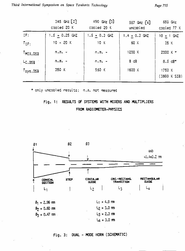
highest frequency receivers are tabulated in Figure 1. The ever-increasing
https://ntrs.nasa.gov/search.jsp?R=19930018595 2018-11-08T09:14:30+00:00Z

Third International Symposium on Space Terahertz Technology page
importance of atmospheric investigations in the higher sub-millimeter
wavelength-range has led to a consolidated program to reach 1 THz with
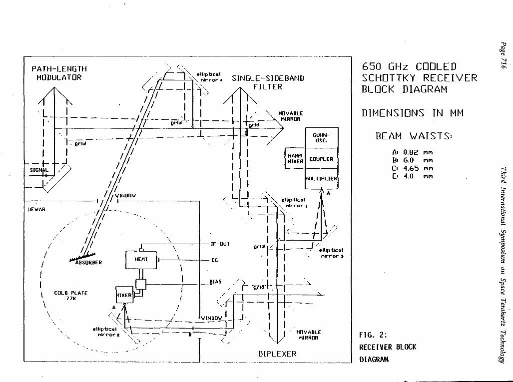
such instruments. To this end a radiometer (s.- Fig.2) has been construc-
ted for the detection of the CIO molecule at 649 GHz; this is the sub-
ject of this paper.
The three principal sections of the system are the optics, the all solid-
state local oscillator and the low-noise mixer-preamplifier.
QUASI-OPTICS
At frequencies above 200 GHz the losses of waveguide components are too
high for sensitive radiometers, and quasi-optical systems become increa-
singly compact. The prime component requirements for coupling the anten-
na and local oscillator into the mixer are high efficiency feed-horns,
precisely machined ofset-mirrors and low-loss wire grids for polarising
couplers and filters. All mirrors are ellipsoids, whilst grids comprise
20 um diameter tungsten wire with 50 um spacings (between centres).
For IF bandwidths Af/f <_ 0.5 the Martin-Puplett coupler is preferred.
Figure 2 shows the total front-end schematic, including a single-side-
band filter and path-length modulator (from University of Bremen, to be
reported at this conference). The quasi-optical' beams, beam-waist loca-
tions and sizes are also shown. The feedhorns in this receiver are dual-
mode horns as shown schematically in Figure 3 £5"] . These horns have been
measured at lower frequencies and have in all cases symmetrical near gaus-
sian beam-patterns, to at least -15 dB. The losses of the optics plus feed-
horns were measured by connecting the output of the frequency multiplier
Page 708 Third International Symposium on Space Terahertz Technology
direct ly to the mixer, and then feeding the l.o. to the mixer via the
two horns and the quasi-optics: the loss was around 1 dB.
LOCAL OSCILLATOR
The local oscillator power requirement for a mixer depends strongly on the
diode quality and on the mixer mount- and coupling-losses between source
and mixer. Particularly in the submillimeter-range these parameters are not
easy to determine. By extrapolating from lower submillimeter-wavelength, we
estimate the l.o. power requirement to be in the range 100 uW to 1 mW for a
cooled mixer. The requirement was to build an all solid-state source for la-
ter space application.
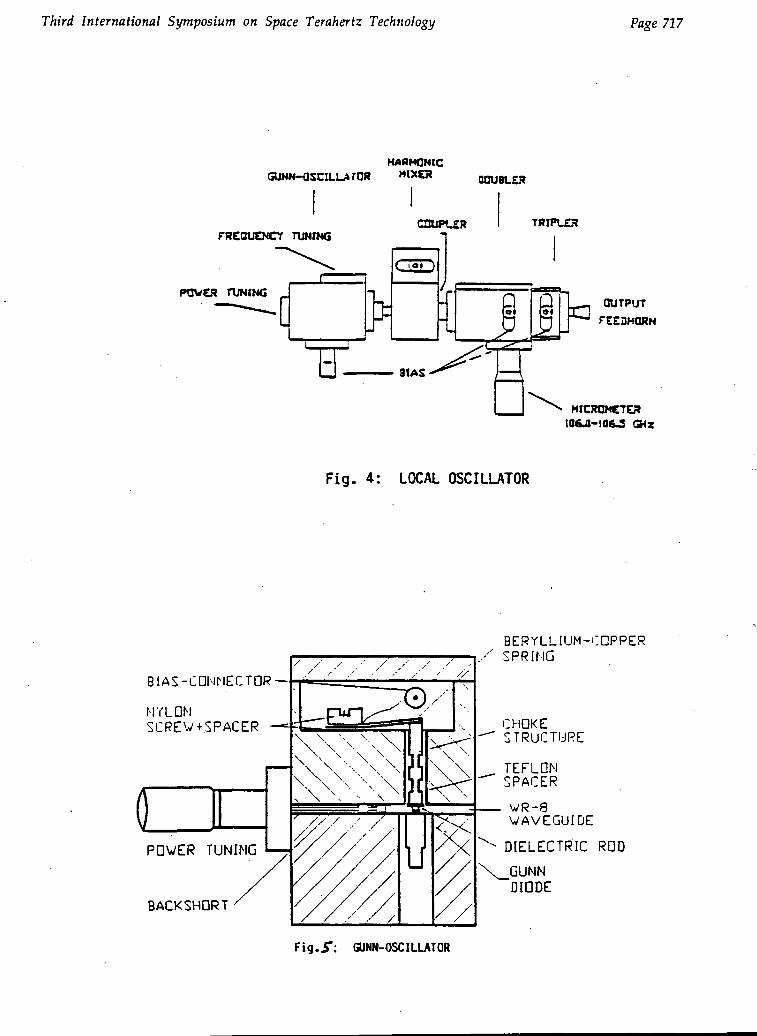
In this paper the source comprises a Gunn oscillator, a waveguide cross-
coupler plus harmonic mixer, a waveguide frequency doubler and tripler. All
components are directly connected together, to reduce losses (Figure 4).
(a) Gunn-Oscillator
A Varian InP Gunn diode is mounted into a WR-8 waveguide (Figure 5). Bias
is supplied to the diode via a coaxial low-pass filter held by teflon spacers.
The frequency is pretuned by a cap-resonator, fine adjustment over several
GHz being provided by a dielectric tuning rod sliding under the cap. A wave-
guide back-short allows adjusting for maximum power. The power output is
shown in Figure 6.
Third International Symposium on Space Terahertz Technology Page 709
(b) Frequency Multiplier
There are several possibilities of attaining power at 650 GHz from a solid
source followed by a multiplier. Gunn oscillators deliver output power up
to 50 mW at frequencies up to 115 GHz. For this reason a sixtupler seems a
natural choice. Though we build one with -TOO uW output power, it was very dif-
ficult to tune, as several idlers had to be optimised simultaneously. The
better choice is a doubler-tripler or tripler-doubler combination, where
each stage can be developed separately. Calculations using the program by
Siegel et al. [6]] showed that the doubler-tripler combination should re-
sult in higher efficiency; hence this combination was chosen.
To facilitate easy system construction and testing, especially for the case
of cascaded multiplication stages, Radiometer-physics developed in 1987
"in-line" waveguide frequency multipliers (Figure 7). This means, that input-
and output-waveguide are in-line, compared to the standard crossguide-type
structure.
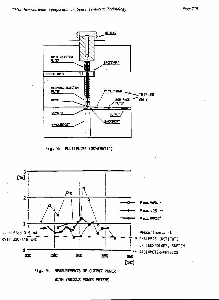
A schematic for both multipliers is shown in Figure 8. Input power is coup-
led from the input waveguide via a probe and coaxial filter to the diode
which is part of the last section of this filter. The filter is of the low-
pass Tchebycheff-type and has been modelled a lower frequencies. Probe and
diode are located in the bend of input- and output-waveguides respectively.
The DOUBLER input waveguide dimensions are 2.0x1.0 mm, which are tapered to
2.0x0.5 mm at the probe. The dimensions of the output waveguide are 0.6x0.3 mm
Backshorts are provided for tuning. The diode is a 6P4 from University of
Virginia, with the following DC-parameters Rs =.12 ohm , Cj = 18 fF,
•Vbr = 20 V. It is contacted by a whisker of length '0.3 mm and diameter 25 urn.
Page 710 Third International Symposium on Space Terahertz Technology
.With 50 mW input signal an efficiency of 20% was achieved, compared with a
theoretical efficiency of 37%. Power was measured with a Hughes Thermistor
mount at the input. Output power was measured with an Anritsu power head
140-220 GHz with a tapered transition to match the input waveguide of the
multiplier
The TRIPLER input and output waveguide dimensions are 0.6x0.3 mm and
0.4x0.2 mm respectively. It operates with a diode 2T2 again from University
of Virginia. Its DC-characteristics are Cj = 6.0 fF, Rs = 12 ohm, Vbr = -11V.
The whisker is 0.2 mm long, with 12 gm diameter. An important feature of
the tripler is the idler tuning circuit in form of a stub waveguide with a
moving short. The output waveguide contains a short section of reduced-width
waveguide to prevent idler propagation to the output. Low frequency model-
ling was important in attaining optimum waveguide dimensions. The output po-
wer achieved was 300 uW, which means an efficiency of 3% compared to 17% the-
oretical.
The measurement of output power in the range 600-700 GHz is not trivial, and
caution should be taken in specifying power at such high frequencies - in
particular the power standards should be quoted. In our case relative mea-
surements were performed using the same Anritsu thermistor power-head as
for the doubler, with appropiate waveguide transitions. The absolute power
output was then measured with the Queen Mary College acoustic calorimeter
at 624 GHz, where an absolute calibration exists: this showed that the ab-
solute power from the l.o. input is about three times greater than the.An-
ritsu reading. Hence to a first approximation we can multiply all Anritsu
readings by factor 3. Absolute measurements were also performed at 690 GHz
with a similar frequency multiplier chain, whereby 30 uW were measured with
the Anritsu head and 90 uW with the QMC instrument - once again a factor 3.

Third International Symposium on Space Terahertz Technology Page 711
It is relevant to draw attention to the problems arising due to using
different lower frequency thermistor heads, this is illustrated in
Figure 10 for three measurements from a 345 GHz frequency multiplier. -
To show the possibilities of achieving l.o. power from solid-state sour-
ces in the submm-range we have included Figure 10.
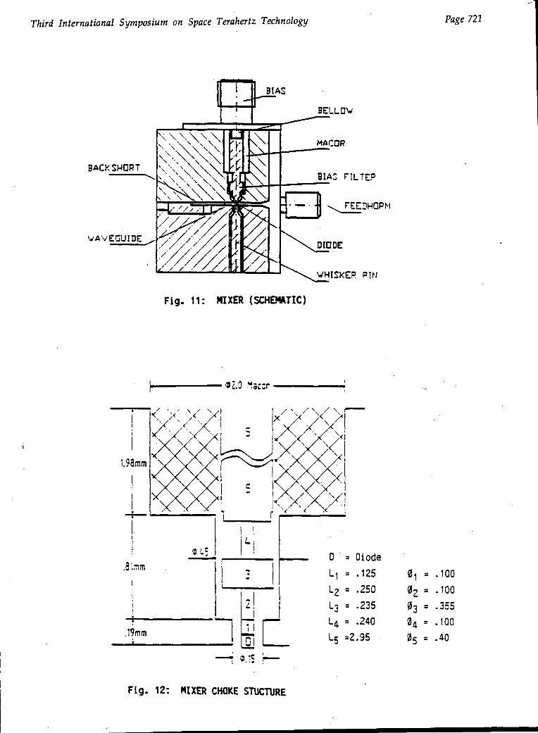
MIXER
The mixer is shown schematically in Figure 11. The dual-mode horn is identi-
cal to that used for the l.o. output. The waveguide dimensions are 0.6x0.2 mm
and the contacting back-short is gold-plated beryllium-copper. The diode
chip (type 1T6 from the University of Virginia) is mounted on the coaxial
choke structure, as shown in Figure 12. The chip is turned down to a cylin-
drical form and gold plated on the cylindrical surface, so that the chip is
also the first choke-section. It is seen that the choke is supported by a.
Macor disc: the dimensions of this disc are important for obtaining a broad
i.f. bandwidth. The calculated impedance of the choke is shown in Figure 14
from d.c. to 1100 GHz. Figure 15 shows the measured output impedance of the
mixer across the i.f. band 9-11 GHz, without and with an i.f. matching trans-
former
The 1T6 diode has the following d.c.-characteristics: Rs =-30 ohm
Cjo = 0-35 fF, Vbr = -6 V. The whisker is of gold-plated phosphorbronze,
diameter 7 urn; the total whisker length is 0.2 mm, and includes a loop to
take up slight changes in waveguide and choke dimensions on cooling the
mixer to 77 K. To test that there was adequate l.o. power the diode was
biased at room-temperature to 0.86 V, whereby the diode drew a current of
Page 712 Third International Symposium on Space Terahertz Technology
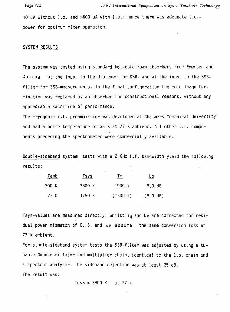
10 pA without l.o. and >600 uA with l.o.: hence there was adequate l.o.-
power for optimum mixer operation.
SYSTEM RESULTS
The system was tested using standard hot-cold foam absorbers from Emerson and
Cuming at the input to the diplexer for DSB- and at the input to the SSB-
filter for SSB-measurements. In the final configuration the cold image ter-
mination was replaced by an absorber for constructional reasons, without any
appreciable sacrifice of performance.
The cryogenic i.f. preamplifier was developed at Chalmers Technical University
and had a noise temperature of 35 K at 77 K ambient. All other i.f. compo-
nents preceding the spectrometer were commercially available.
Double-sideband system tests with a 2 GHz i.f. bandwidth yield the following
results:
Tamb Tsys Tm l_o
300 K 3800 K 1900 K 8.0 dB
77 K 1750 K (1500 K) (8.0 dB)
Tsys-values are measured directly, whilst TM and L^ are corrected for resi-
dual power mismatch of 0.15, and we assume the same conversion loss at
77 K ambient.
For single-sideband system tests the SSB-filter was adjusted by using a tu-
nable Gunn-oscillator and multiplier chain, identical to the l.o. chain and
a spectrum analyzer. The sideband rejection was at least 25 dB.
The result was:
Tusb = 3800 K at 77 K

Third International Symposium on Space Terahertz Technology PaZe 713
Mere than adequate l.o. power was available to reach minimum Tsys. It
was noted that the noise temperature was fairly insensitive to changes
in diode current in the range 400-800 uA.
The system has been flown on an aircraft contracted by the University
of Bremen. A first uncorrected result shows the CIO line in Fig. 15.
PROSPECTS
It appears reasonable to expect spaceborne all-solid-state radiometer system
to be feasible at least to 1 THz, using only waveguide techniques. Calcula-
tions using the computer model of Siegel and Kerr yield l.o. output powers
of 360 uW at 1 THz; taking into account losses this still implies that suf-
ficient l.o. power will be available at 1 THz to pump a Schottky-barrier
mixer diode; such a development program has commenced at Radiometer-physics.
Since completing the 650 GHz system new Schottky-barrier mixer diodes have
been reported [7l , Csl . Hence, with improvements in multiplier- and
mixer-technology it should be possible to operate such systems at even higher
frequencies.
ACKNOWLEDGEMENT
The authors express their thanks to:
Dr. Nett from University of Bremen and Dr. Albinson from Chalmers Institute
of Technology, Sweden for their helpful collaboration
Dr. Th. Crowe from University of Virginia for providing the excellent Scfiottky
barrier diodes
Dr. E. Armandillo for support under ESA contract: "Limb Sounder critical Re-
ceiver Technologies for Remote Sensing of the Atmosphere".
Mr. P. Leipold of Radiometer-physics for his indefatigable support

Page 714 • Third International Symposium on Space Terahertz Technology
R E F E R E N C E S
1 P. Hartogh, G.K. Hartmann, P. Zimmermann"Simultaneous Water Vapour and Ozone Measurements with Mlllimeterwavesin the Stratosphere and Mesophere". IGRASS 3.-6. Juni Helsinki, 1991
2 F. Lewen, University of Cologne, private Communication
3 J. Hernichel, R. Schieder, J. Stutzki, B. Vowinkel, G. Winnewisser, P. Zimmermanr"A 492 GHz Cooled Schottky Receiver for Radio-Astronomy"Proceeding of Third Intern. Symposium on Space Terahertz Technology,March 24-26, 1992, Michigan
4 R. Zimmermann, Ra. Zimmermann, P. Zimmermann"All Solid-State Radiometer at 557 GHz", 21st European Microwave ConferenceStuttgart 1991
5 M.H. Picket, J.C. Hardy, J. Farhoomand"Characterisation of a Dual Mode Horn for Submillimeter Wavelengths",IEEE, MTT-32, 1984 (936-937)
(
6 P.H. Siegel, A. R. Kerr, W. Hwang"Topics in the optimisation of millimeter-wave mixers."NASA Techn. Paper 2287, March 1984
7 N. Keen, A. Grub, H. Hartnagel, J. Freyer, H. Grote, Rii. Zimmermann"New Submillimeter-Wave Schottky-Barrier Mixer, Diodes: First Results"Revised late Paper, Stuttgart
8 T.W. Crowe, W.C.B. Peatmann"GaAs Schottky Diodes for Mixing Applications byond 1 THz"Proc. 2nd International Symposium on Space Terahertz Technology, Jet.Propulsion Lab., Febr. 1991 (323-339)
Third International Symposium on Space Terahertz Technology Page 715
345 GHz 12] 490 GHz [3] 557 GHZ [4] 650 GHz
cooled 20 :< cooled 20 :< uncooled cooled 77 :<
IF:
TIF:
TMIX,DS3
LC,OS3
Tsys,OS3
1.5 * 0.25 GHZ
10 - 20 :<
n.m. -
350 !<
1.5 ^ 0.3 GHZ
10 K
550 <
1.4 ^ Q.3 GHZ
60 K
1200 :<
8 dB
1600 K
10 i 1 GHZ
35 K
2000 '< *
8.3 dB*
1750 <
(3800 < S33)
* only uncooled results; n..n. not measured
Fig. 1: RESULTS OF SYSTEM WITH MIXERS AND MULTIPLIERS
FROM RADIOMETER-PHYSICS
4 CONICAL1 SECTION
axb
=0.4x0.2 m
CIRCULARGUIDE
CBC.-fl£CTANG.TRANSITION
RECTANGULARGUIDE
L2
01 = 2.96 inn02 = 0.60 irm03 = 0.47 mn
LI = 4.9 mn
L£ = 3.0 nra13 = 2.3 urn14 = 3.0 mn
Fig. 3: DUAL - MODE HORN (SCHEMATIC)
Page 716T
hird International
Symposium
on
Space Terahertz
Technology
c*u
D>y*i
n u
2;
o*g
u
<>• 2;
N ^
QX
H-
LD i- :̂
nu
o x
nin
u _
jsD
(/) CQ
MMMENSIONS
c eE
E
e\jCD O \D
O">
e\j in
U
j25m
cvj >
<
• U
J
Oto
o
<M
LU
•—
u. as
a
1_l
UJ
a_
-T/v.
u U
'v-. ' £
Third International Symposium on Space Terahertz Technology Page 717
HARMONICGUNNH3SClLL-»raR M'XG* DOUBLES
C3UPT_£R TRIPVE3FREQUENCY TUNING
raven TUNINGOUTPUT
• MICSOMCTER106JJ-106J GHz
Fig. 4: LOCAL OSCILLATOR
BI A S - C O N N E C T O R —
NYLDNSCREW +.SPACER
POWER TUNING
BACKSHORT
BERYLLIUM-COPPERSPRING
CHOKESTRUCTURE
TEFLONSPACER
. WR-8W A V E G U I D E
D I E L E C T R I C ROD
_GUNNDIODE
Fig.5": GUNN-OSCILLATOR

Page 718Third International Symposium on Space Terahertz Technology
40 -Li i •I !—
I 98 100 102 104 106 108
Fig. 6: GUNN OSCILLATOROUTPUT POWER
FREO.GHz
[NPWAVE
1
STAGEi
OUTPUTTUNING
STAGES
OUTPUTTUNING
UT-GUIDE
r
rt̂
*
.
INPUTTUNING
INPUTTUNING
OUTPUT- •WAVEGUIDE
Fig. 7: ARRANGEMENT OF WAVEGUIDES
FOR IN-LINE MULTIPLIERS
Third International Symposium on Space Terahertz Technology Page 719
N
INPUT REJECTIONRUTS*
V
MP-JT
HARKONC REJECTONR.TS3
OIOOE
WHSKES
OL£3 1JMNC.TRIPLER
Fig. 8: MULTIPLIER (SCHEMATIC)
^* I
specified 0.5 mWover 330-345"W
323 130 340 350
Pcut MRS
36Q
Measurements at:* CHALMERS INSTITUTE
OF TECHNOLOGY, SWEDEN
RADIOMETER-PHYSICS
Fig. 9: MEASUREMENTS OF OUTPUT POWER
WITH VARIOUS POWER METERS

Page 720 Third International Symposium on Space Terahertz Technology
iOmW
5mW
1m W
5(%W
100|iWr-
50|iW
hI
r
RADIOMETER
PHYSICS
MULTIPLIER
DATA
10jiW
a $
x2x3
* x6* x3x2® x2x3
$
c
* • *
RESISTIVEMJLTTPUCATJONQM.Y
200 300 400 500 600 700 GHzFig. 10 POWER OUTPUTS FROM VARIOUS MULTIPLIERS
Third International Symposium on Space Terahertz Technology Page 721
BELLOV
BACKSHORT
FEEDHQPM
WAVEGUIDE
Fig. 11: MIXER (SCHEMATIC)
.19mm •! r~ L4= •ml Ls -2.
D = Diode
= .125
L2 = .250
L3 = .235
= .240
95
03 =
04 =
05 =
.100
.100
.355
.100
.40
Fig. 12: MIXER CHOICE STUCTURE

Page 722 Third International Symposium on Space Terahertz Technology
Fig. 13: MIXER CHOKE RF-IMPEDANCE
Fig. 14: MIXER IF-IMPEDANCE 9-11 GHZ
A: before B: after matching

Third
International Symposium
on
Space Terahertz
Technology
Page 723
L
VI
qo"CD
qcd
J o
J O
r T
J O
O
Ho <i>-, CN
03
LUO.
LUOLOO)