
i PROCESS DAMPING TECHNIQUE FOR ALUMINIUM ALLOY...
24
i PROCESS DAMPING TECHNIQUE FOR ALUMINIUM ALLOY AT LOW SPEED MACHINING MOHD AZFADIR BIN MAT DAUD Thesis submitted in partial fulfilment of the requirements for the award of Bachelor of Mechanical Engineering Faculty of Mechanical Engineering UNIVERSITI MALAYSIA PAHANG JUNE 2012
Transcript of i PROCESS DAMPING TECHNIQUE FOR ALUMINIUM ALLOY...

i
PROCESS DAMPING TECHNIQUE FOR ALUMINIUM
ALLOY AT LOW SPEED MACHINING
MOHD AZFADIR BIN MAT DAUD
Thesis submitted in partial fulfilment of the requirements
for the award of Bachelor of Mechanical Engineering
Faculty of Mechanical Engineering
UNIVERSITI MALAYSIA PAHANG
JUNE 2012
vii
ABSTRACT
This thesis investigated the process damping performance of tools when machining
aluminium alloy at low speed. The objective of this thesis is to prepare the aluminum
alloy workpiece for cutting experiment. Second objective of this project is machining
the aluminium alloy workpiece with process damping technique which is using high
axial depth of cut and low radial depth of cut. The third objective is to compare
process damping performance between three different helix tools. The thesis
implants process damping techniques to investigate the fatigue process damping
performance between tool types. All tools used in this project are uniform helix tools
which represent by solid carbide tool, high speed steel coated tool and solid carbide
coated tool. By performing machining which is milling process on CNC Haas VF6
vertical milling machine, data for process damping performance is recorded. From
the data, process damping wavelength will be calculated for the comparison of
performance. The result obtained indicated that the solid carbide tool have the lowest
process damping wavelength while high speed steel coated tool have higher process
damping wavelength than solid carbide coated tool. The highest process damping
wavelength goes to solid carbide coated tool. As a conclusion, solid carbide coated
gave the best performance of machining aluminium alloy at low speed.
viii
ABSTRAK
Tesis ini berkaitan dengan prestasi proses redaman untuk alat apabila pemesinan aloi
aluminium pada kelajuan rendah di lakukan. Objektif tesis ini adalah menyediakan
bahan kerja aluminium aloi untuk eksperimen memotong. Objektif kedua ialah
memesin bahan kerja aluminium aloi dengan teknis proses redaman yang
menggunakan nilai tinggi bagi kedalaman paksi kedalaman dipotong dan nilai rendah
dalam jejari kedalaman pemotongan. Objektif ketiga ialah untuk membandingkan
prestasi proses redaman antara tiga alat helix yang berbeza.Implan tesis memproses
teknik redaman adalah untuk menyiasat prestasi proses redaman lesu antara jenis
alat. Semua alat yang digunakan dalam projek ini adalah jenis helix seragam yang
diwakili oleh alat karbida pepejal,alat keluli bersalut berkelajuan tinggi dan alat
karbida pepejal bersalut. Dengan melakukan pemesinan yang merupakan proses
penggilingan menggunakan mesin Komputer Kawalan Berangka Haas VF6, data
untuk prestasi proses redaman direkodkan. Daripada data yang didapati, panjang
gelombang proses redaman akan dikira untuk membandingkan prestasi proses
redaman. Keputusan yang diperolehi menunjukkan bahawa alat karbida pepejal
mempunyai panjang gelombang proses redaman yang terendah manakala alat keluli
berkelajuan tinggi mempunyai panjang gelombang proses redaman yang lebih tinggi.
Panjang gelombang proses redaman yang tertinggi didapati oleh alat karbida pepejal
bersalut. Keputusan menyimpulkan bahawa alat karbida pepejal bersalut memberikan
prestasi terbaik dalam pemesinan aluminium aloi pada kelajuan rendah.
ix
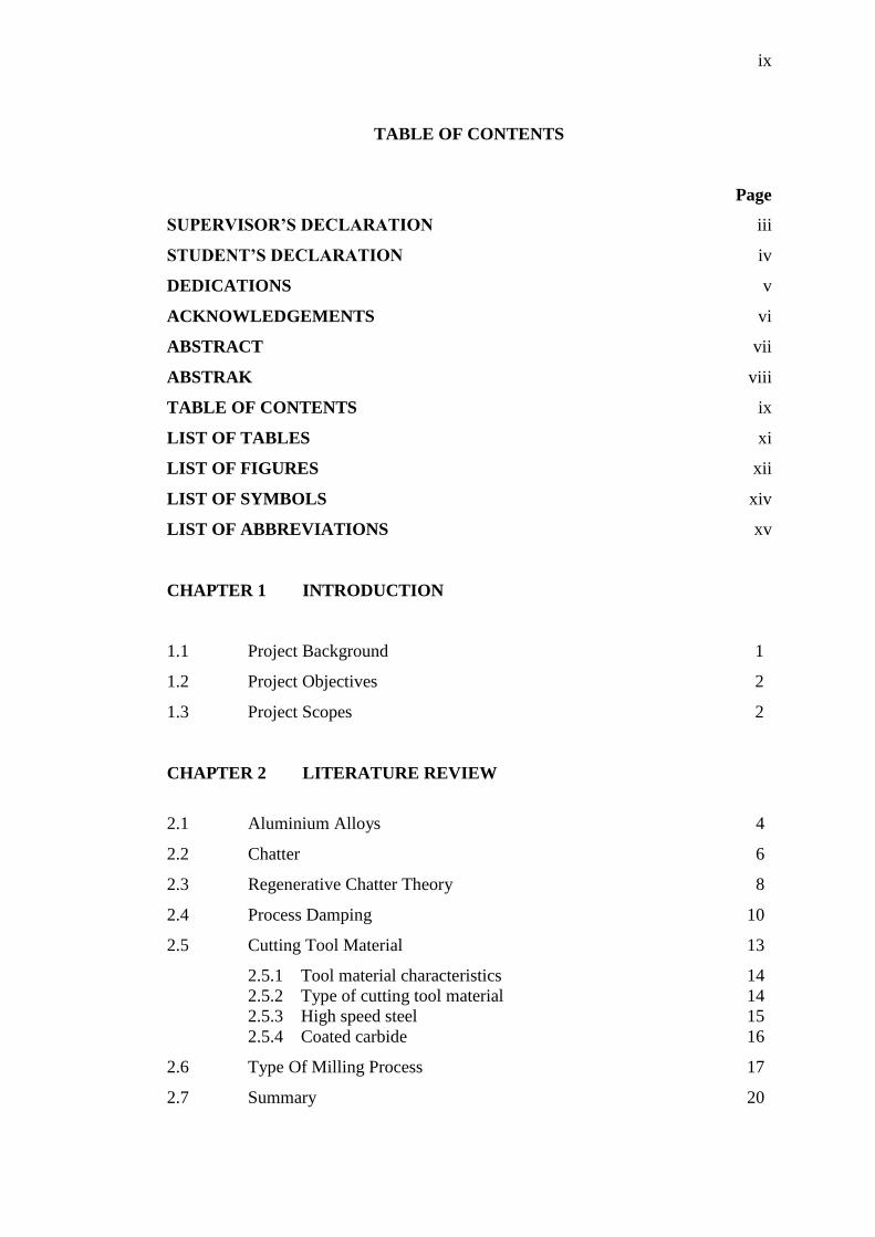
TABLE OF CONTENTS
Page
SUPERVISOR’S DECLARATION iii
STUDENT’S DECLARATION iv
DEDICATIONS v
ACKNOWLEDGEMENTS vi
ABSTRACT vii
ABSTRAK viii
TABLE OF CONTENTS ix
LIST OF TABLES xi
LIST OF FIGURES xii
LIST OF SYMBOLS xiv
LIST OF ABBREVIATIONS xv
CHAPTER 1 INTRODUCTION
1.1 Project Background 1
1.2 Project Objectives 2
1.3 Project Scopes 2
CHAPTER 2 LITERATURE REVIEW
2.1 Aluminium Alloys 4
2.2 Chatter 6
2.3 Regenerative Chatter Theory 8
2.4
2.5
Process Damping
Cutting Tool Material
10
13
2.5.1 Tool material characteristics 14
2.5.2 Type of cutting tool material 14
2.5.3 High speed steel 15
2.5.4 Coated carbide 16
2.6
2.7
Type Of Milling Process
Summary
17
20
1 × ENTER (1.5 line spacing)
x
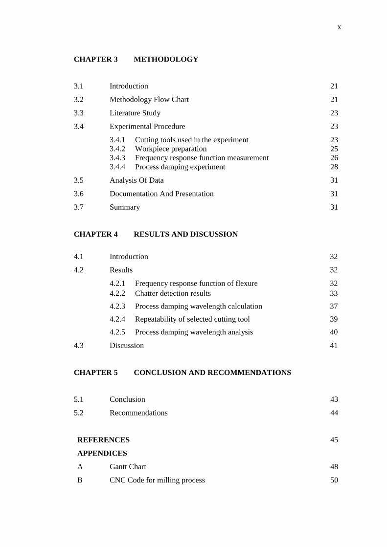
CHAPTER 3 METHODOLOGY
3.1 Introduction 21
3.2 Methodology Flow Chart 21
3.3 Literature Study 23
3.4 Experimental Procedure 23
3.4.1 Cutting tools used in the experiment 23
3.4.2 Workpiece preparation 25
3.4.3 Frequency response function measurement 26
3.4.4 Process damping experiment 28
3.5
3.6
3.7
Analysis Of Data
Documentation And Presentation
Summary
31
31
31
CHAPTER 4 RESULTS AND DISCUSSION
4.1 Introduction 32
4.2 Results 32
4.2.1 Frequency response function of flexure 32
4.2.2 Chatter detection results 33
4.2.3 Process damping wavelength calculation 37
4.2.4 Repeatability of selected cutting tool 39
4.2.5 Process damping wavelength analysis 40
4.3 Discussion 41
CHAPTER 5 CONCLUSION AND RECOMMENDATIONS
5.1 Conclusion 43
5.2 Recommendations 44
REFERENCES
45
APPENDICES
A Gantt Chart 48
B CNC Code for milling process 50
xi
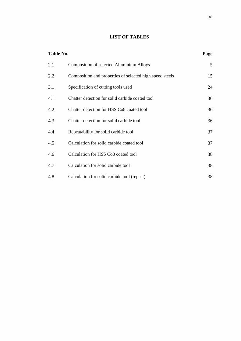
LIST OF TABLES
Table No. Page
2.1 Composition of selected Aluminium Alloys 5
2.2 Composition and properties of selected high speed steels 15
3.1 Specification of cutting tools used 24
4.1 Chatter detection for solid carbide coated tool 36
4.2 Chatter detection for HSS Co8 coated tool 36
4.3 Chatter detection for solid carbide tool 36
4.4 Repeatability for solid carbide tool 37
4.5 Calculation for solid carbide coated tool 37
4.6 Calculation for HSS Co8 coated tool 38
4.7 Calculation for solid carbide tool 38
4.8 Calculation for solid carbide tool (repeat) 38
xii
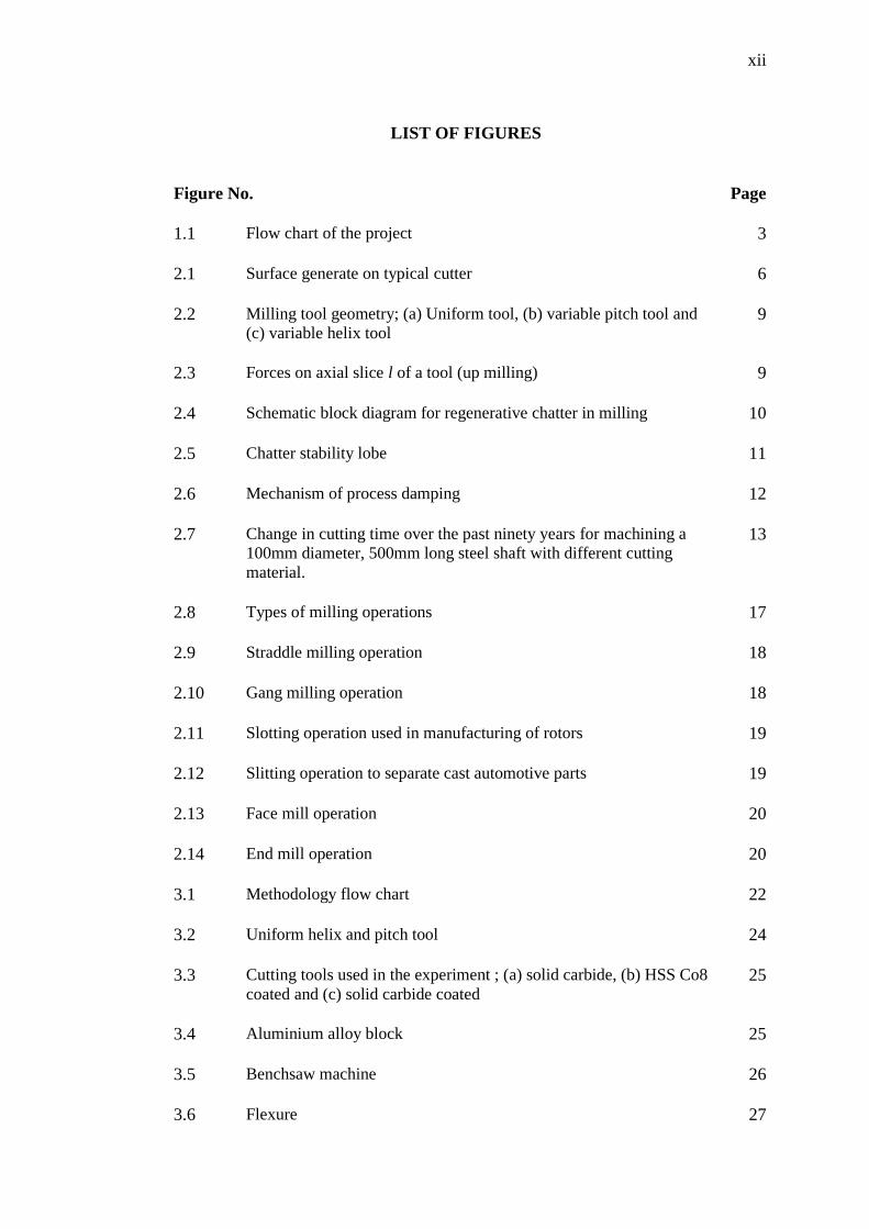
LIST OF FIGURES
Figure No. Page
1.1 Flow chart of the project 3
2.1 Surface generate on typical cutter 6
2.2 Milling tool geometry; (a) Uniform tool, (b) variable pitch tool and
(c) variable helix tool 9
2.3 Forces on axial slice l of a tool (up milling) 9
2.4 Schematic block diagram for regenerative chatter in milling 10
2.5 Chatter stability lobe 11
2.6 Mechanism of process damping 12
2.7 Change in cutting time over the past ninety years for machining a
100mm diameter, 500mm long steel shaft with different cutting
material.
13
2.8 Types of milling operations 17
2.9 Straddle milling operation 18
2.10 Gang milling operation 18
2.11 Slotting operation used in manufacturing of rotors 19
2.12 Slitting operation to separate cast automotive parts 19
2.13 Face mill operation 20
2.14 End mill operation 20
3.1 Methodology flow chart 22
3.2 Uniform helix and pitch tool 24
3.3 Cutting tools used in the experiment ; (a) solid carbide, (b) HSS Co8
coated and (c) solid carbide coated 25
3.4 Aluminium alloy block 25
3.5 Benchsaw machine 26
3.6 Flexure 27

xiii
3.7 Bruel&Kjaer model type 7539A 5/1 channel 27
3.8 2302-10 Meggit hammer 27
3.9 Bruel& Kjaer 4507B accelerometer 27
3.10 CNC Haas VF6 vertical milling machine 29
3.11 Machining apparatus and position of workpiece 29
3.12 Schematic diagram of the cutting procedure 30
3.13 PCB 352C33 accelerometer 30
3.14 Hi-Speed USB Carrier NI USB-9162 30
4.1 Frequency response function of the flexure 33
4.2 Stable condition with n=1414 rpm and f=566 mm/min; (a)
acceleration amplitude and (b) frequency domain graph 33
4.3 Stable condition with n=2278 rpm and f=911 mm/min(a)
acceleration amplitude and (b) frequency domain graph 34
4.4 Stable condition with n=4885 rpm and f=1953 mm/min; (a)
acceleration amplitude and (b) frequency domain graph 34
4.5 Chatter detection at n=5373 rpm and f=2149 mm/min; (a)
acceleration amplitude and (b) frequency domain graph 35
4.6 Repeatability test on tool 3(regular solid carbide) 39
4.7 Comparison of process damping wavelength for each tool 40

xiv
LIST OF SYMBOLS
λc Process damping wavelength
Maximum chip thickness
Feed per tooth
µ Micro
γ Relief angle
xv
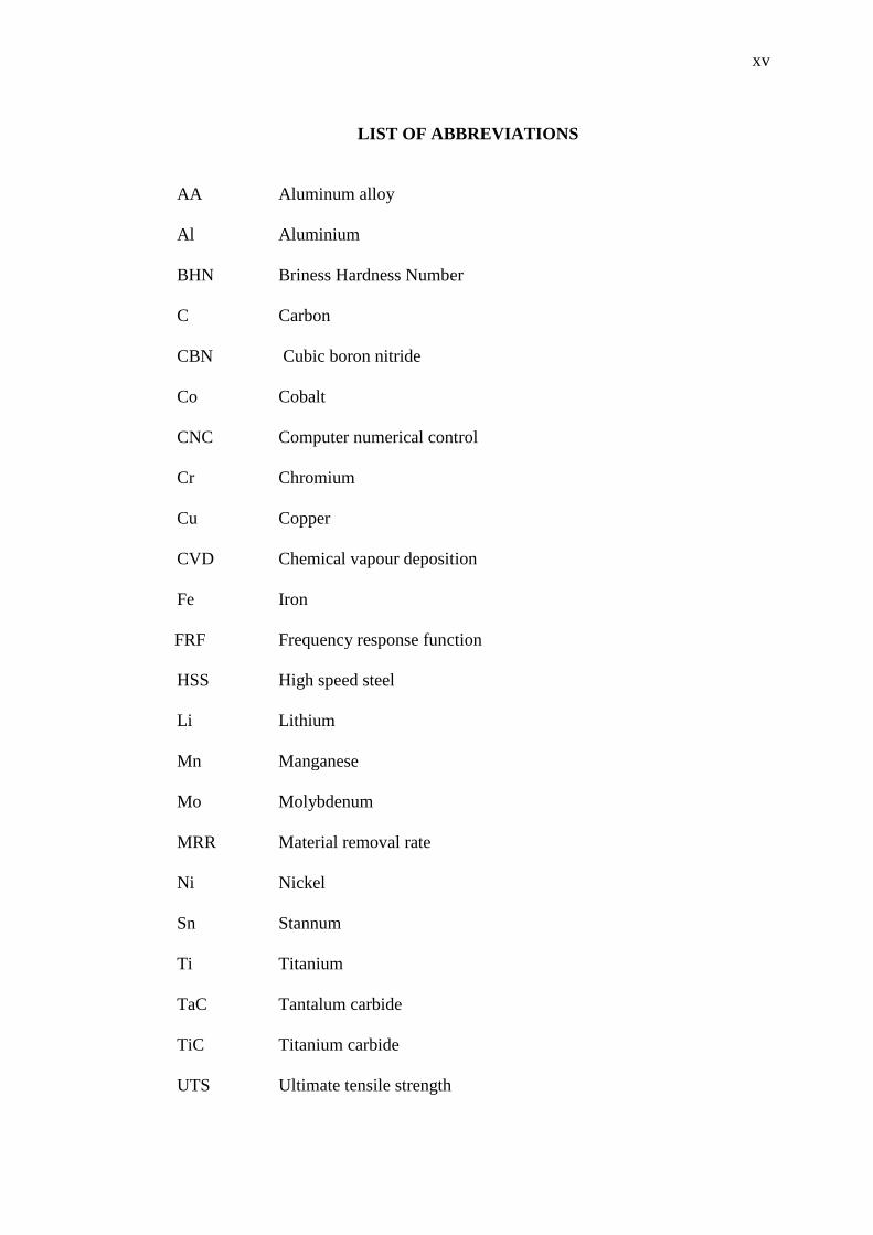
LIST OF ABBREVIATIONS
AA Aluminum alloy
Al Aluminium
BHN Briness Hardness Number
C Carbon
CBN Cubic boron nitride
Co Cobalt
CNC Computer numerical control
Cr Chromium
Cu Copper
CVD Chemical vapour deposition
Fe Iron
FRF Frequency response function
HSS High speed steel
Li Lithium
Mn Manganese
Mo Molybdenum
MRR Material removal rate
Ni Nickel
Sn Stannum
Ti Titanium
TaC Tantalum carbide
TiC Titanium carbide
UTS Ultimate tensile strength

xvi
V Vanadium
W Tungsten
WC Tungsten carbide
Zn Zinc
Zr Zirconium
1
CHAPTER 1
INTRODUCTION
1.1 PROJECT BACKGROUND
Aluminium alloy is a silverish white metal that is very light compared to
other metals such as brass, nickel, steel and copper. It has a very strong corrosion
resistance and also a good electrical conductivity. Furthermore, aluminium alloy is
having good machinability as it can be turned, milled and bored in the machining
process. Aluminium alloy have been the prime material of construction for the
aircraft industry for making aircraft airframes. Besides that, it’s also widely used in
sports equipment and also for high pressure gas cylinders. The costs of aluminium
alloy are relatively low compared to titanium alloy. So, in this project, technique to
machine this aluminium alloy is done to investigate the process damping
performance between different tool types.
A good machinability is one of the characteristics or the advantage of
aluminium alloy. In milling process chatter can still be occur and gives bad surface
finish to the machined surface. Chatter is one problem that needs to be overcome as
it can damage the tools and the machines itself. Process damping performance for
tools when milling this material will be observed. At low cutting speed process the
damping process will occur. The process damping region can be known by observing
chatter stability diagram
Therefore, in this project, frequency response of function is initially
determined for the flexural system of single degree of freedom. Low radial and high
depths of cut are used as cutting process for achieving damping behaviour at low
2
speed. Chatter frequency and surface speed is use to determine process damping
performance. A regular milling tool performance which is regular solid carbide is
compared with solid carbide coated tool and High Speed Steel (HSS) coated tool.
1.2 PROJECT OBJECTIVES
These are the objective of this research:
i. To prepare Aluminium Alloy workpiece.
ii. To machining Aluminium Alloy using uniform helix milling tools with
process damping technique.
iii. To compare process damping performance between three different helix
milling tools.
1.3 PROJECT SCOPES
The project needs to prepare workpiece of the material which is Aluminium
Alloy. The flexural holds the workpiece also need to be done. Then, the frequency
response of the flexural should be determined. When machining Aluminium Alloy
using CNC milling machine, it needs to use low radial and high axial depth of cut.
Cutting tools for the machining process should be varying in type which are regular
solid carbide tool and coated tools. Process damping performance between the tools
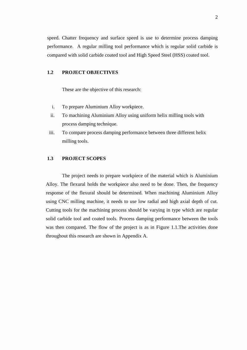
was then compared. The flow of the project is as in Figure 1.1.The activities done
throughout this research are shown in Appendix A.
3
Figure 1.1: Flow chart of the project
YES
Finish
Methodology
Determining all research requirement
Literature review
Objectives, scopes and
background of research
Start
Machining/ experiment
Discussion and conclusion of the research
NO
Project presentation
Submission of FYP report
Result analysis
4
CHAPTER 2
LITERATURE REVIEW
2.1 ALUMINIUM ALLOYS
Aluminium alloy are categorized in two types which is cast alloys and
wrought alloys. Cast alloys is the alloy that solidified from liquid and used without
any mechanical processing while wrought alloy is involving mechanical processing.
Their identification and designations are referred to Aluminium Association. This
association divide these alloys into different nomenclatures. Two-and three-digit
numbers are used for castings whereas four-digit designations are used for wrought
alloys.
Aluminium with additives among Cu, Mn, Si, Mg, Mg+Si, Zn and Cu+Li are
normally applied. Based on these, the 2xxx (Al-Cu) ,the 6xxx (Al-Mg-Si) and the
7xxx (Al-Zn) alloys are strengthened by aging or precipitation hardening process, to
strength levels corresponding to those of low strength alloy steels up to 100ksi UTS
and 90-95 ksi yield strength. The highest strengths results in the Al-Zn alloy such as
AA 7075 in the age hardened tempers T4 or T6. Therefore, the 7xxx series alloy has
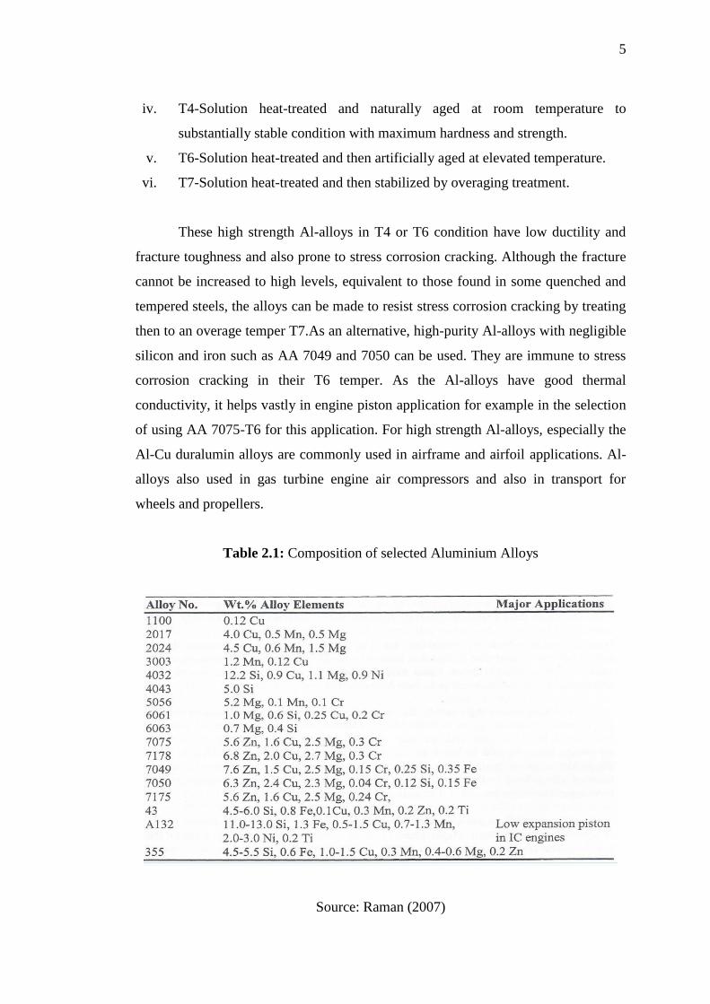
been designated as high strength Al-alloys. The compositions and temper
designations for aluminium alloy are shown in Table 2.1. The temper designation for
aluminium alloys are stated as follows:
i. F-As fabricated, O-Annealed, H-Strain hardened, W-Solution heat-treated.
ii. T- Thremally-treated to produce stable tempers other than F, O and H.
iii. T2-Annealed (for cast product only)
5
iv. T4-Solution heat-treated and naturally aged at room temperature to
substantially stable condition with maximum hardness and strength.
v. T6-Solution heat-treated and then artificially aged at elevated temperature.
vi. T7-Solution heat-treated and then stabilized by overaging treatment.
These high strength Al-alloys in T4 or T6 condition have low ductility and
fracture toughness and also prone to stress corrosion cracking. Although the fracture
cannot be increased to high levels, equivalent to those found in some quenched and
tempered steels, the alloys can be made to resist stress corrosion cracking by treating
then to an overage temper T7.As an alternative, high-purity Al-alloys with negligible
silicon and iron such as AA 7049 and 7050 can be used. They are immune to stress
corrosion cracking in their T6 temper. As the Al-alloys have good thermal
conductivity, it helps vastly in engine piston application for example in the selection
of using AA 7075-T6 for this application. For high strength Al-alloys, especially the
Al-Cu duralumin alloys are commonly used in airframe and airfoil applications. Al-
alloys also used in gas turbine engine air compressors and also in transport for
wheels and propellers.
Table 2.1: Composition of selected Aluminium Alloys
Source: Raman (2007)

6
2.2 CHATTER
Chatter is produced from self-excited vibration during cutting resulting in
high amplitude unstable motion. Self-excited vibrations are based on regeneration of
the waviness of the surface generated in subsequent cuts. These subsequent cuts are
produced by adjacent teeth of the cutter as seen in Figure 2.1. Every cutter removes
the material from an undulated surface left by the previous cutter, and leaves behind
another undulated surface which becomes the source of self-excitation. It has been
shown that at a given speed, increasing the cutter diameter causes the drillstring to
transform from a stable system, where vibrations tend to die out, to a system where
vibrations build up over time (chatter) until they reach saturation. Saturation can be
caused by process nonlinearities such as the cutter jumping out of the cut.
Figure 2.1: Surface generate on typical cutter
Source: Eslayed et al. (1994)

7
Referring to Figure 2.1, the cutting force can be written as (Zamudio, 1988),
(2.1)
where;
b = width of cut (m)
= cutting stiffness of rock formation (N/m2)
C = average feed per cutter blade (m)
X = magnitude of current surface undulation (m)
= magnitude of previous surface undulation (m)
Since C is constant, the variable part of the force causing the vibration is;
(2.2)
This is a simplified form of the force, where is a real number and the
effect of process damping is not included. (Xo-X) is the change in surface position
between current and previous cuts. The effect of process damping on the force was
considered by many investigators to be included in the imaginary component of one
of the parameters affecting the cutting force. These parameters are referred to as
dynamic cutting force coefficients (DCFCs) by Tlusty (1978) and Das and Tobias
(1967).
Basically in theory, the stability boundary is then independent of the feed rate
despite the influence of the feed rate on the mean chip thickness. Apparently, in real
process the empirical cutting stiffness Ks, changes with the feed rate so that the feed
rate does have some influenced on the overall stability.
The feed rate is better express in term of the maximum chip thickness, ;
8
√
(
)
(2.3)
From the equation above, r is the radial immersion of the tool, and D is the
tool diameter, fpt represents feed per tooth which is related to the machining feed rate
f, number of teeth m, and spindle speed n .This is shown in the equation 2.4:
(2.4)
When a high depth of cut are used at low cutting speed, it will results that the
chatter stability will be dominated by process damping effects .Low radial immersion
function to reduce the total machining forces and improve the tool life. This approach
will be employed in the present study in order to determine the process damping
wavelength, λc under different tools types.
2.3 REGENERATIVE CHATTER THEORY
Regenerative chatter is a self-excited vibration that can occur during milling
and other machining processes. It leads to a poor surface finish, premature tool wear,
and potential damage to the machine or tool. Variable pitch and variable helix
milling tools have been previously proposed to avoid the onset of regenerative
chatter.
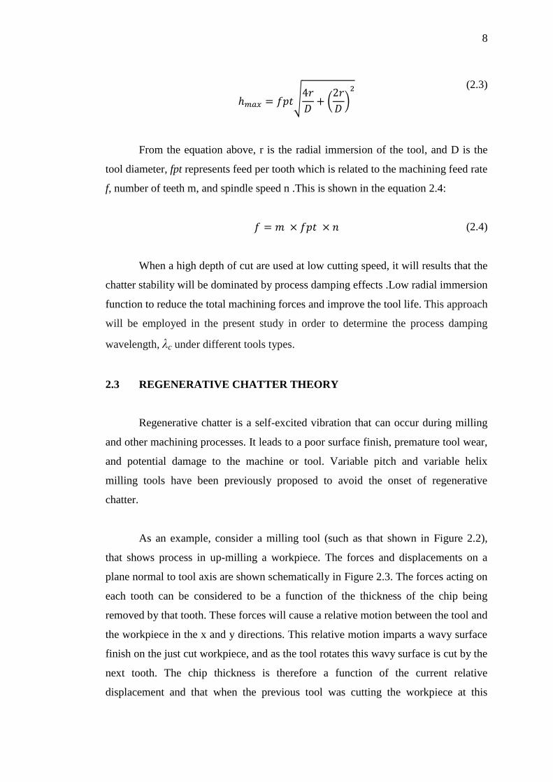
As an example, consider a milling tool (such as that shown in Figure 2.2),
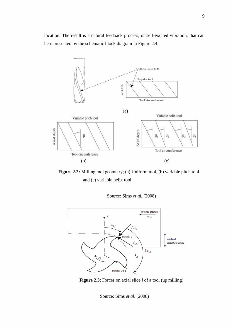
that shows process in up-milling a workpiece. The forces and displacements on a
plane normal to tool axis are shown schematically in Figure 2.3. The forces acting on
each tooth can be considered to be a function of the thickness of the chip being
removed by that tooth. These forces will cause a relative motion between the tool and
the workpiece in the x and y directions. This relative motion imparts a wavy surface
finish on the just cut workpiece, and as the tool rotates this wavy surface is cut by the
next tooth. The chip thickness is therefore a function of the current relative
displacement and that when the previous tool was cutting the workpiece at this
9
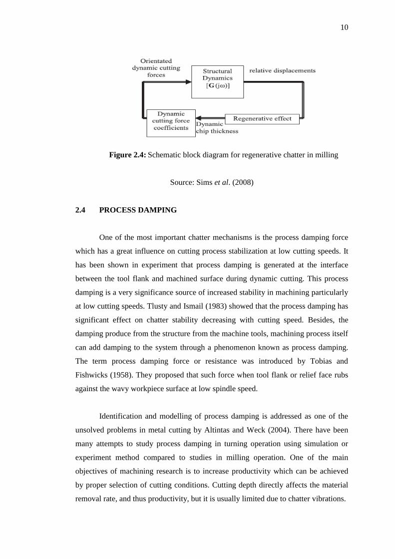
location. The result is a natural feedback process, or self-excited vibration, that can
be represented by the schematic block diagram in Figure 2.4.
(a)
(b)
(c)
Figure 2.2: Milling tool geometry; (a) Uniform tool, (b) variable pitch tool
and (c) variable helix tool
Source: Sims et al. (2008)
Figure 2.3: Forces on axial slice l of a tool (up milling)
Source: Sims et al. (2008)
10
Figure 2.4: Schematic block diagram for regenerative chatter in milling
Source: Sims et al. (2008)
2.4 PROCESS DAMPING
One of the most important chatter mechanisms is the process damping force
which has a great influence on cutting process stabilization at low cutting speeds. It
has been shown in experiment that process damping is generated at the interface
between the tool flank and machined surface during dynamic cutting. This process
damping is a very significance source of increased stability in machining particularly
at low cutting speeds. Tlusty and Ismail (1983) showed that the process damping has
significant effect on chatter stability decreasing with cutting speed. Besides, the
damping produce from the structure from the machine tools, machining process itself
can add damping to the system through a phenomenon known as process damping.
The term process damping force or resistance was introduced by Tobias and
Fishwicks (1958). They proposed that such force when tool flank or relief face rubs
against the wavy workpiece surface at low spindle speed.
Identification and modelling of process damping is addressed as one of the
unsolved problems in metal cutting by Altintas and Weck (2004). There have been
many attempts to study process damping in turning operation using simulation or
experiment method compared to studies in milling operation. One of the main
objectives of machining research is to increase productivity which can be achieved
by proper selection of cutting conditions. Cutting depth directly affects the material
removal rate, and thus productivity, but it is usually limited due to chatter vibrations.
11
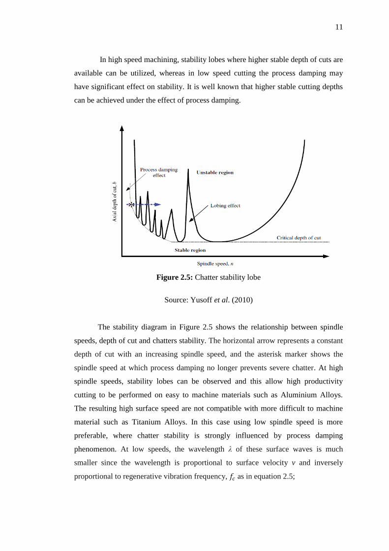
In high speed machining, stability lobes where higher stable depth of cuts are
available can be utilized, whereas in low speed cutting the process damping may
have significant effect on stability. It is well known that higher stable cutting depths
can be achieved under the effect of process damping.
Figure 2.5: Chatter stability lobe
Source: Yusoff et al. (2010)
The stability diagram in Figure 2.5 shows the relationship between spindle
speeds, depth of cut and chatters stability. The horizontal arrow represents a constant
depth of cut with an increasing spindle speed, and the asterisk marker shows the
spindle speed at which process damping no longer prevents severe chatter. At high
spindle speeds, stability lobes can be observed and this allow high productivity
cutting to be performed on easy to machine materials such as Aluminium Alloys.
The resulting high surface speed are not compatible with more difficult to machine
material such as Titanium Alloys. In this case using low spindle speed is more
preferable, where chatter stability is strongly influenced by process damping
phenomenon. At low speeds, the wavelength λ of these surface waves is much
smaller since the wavelength is proportional to surface velocity v and inversely
proportional to regenerative vibration frequency, as in equation 2.5;
12
(2.5)
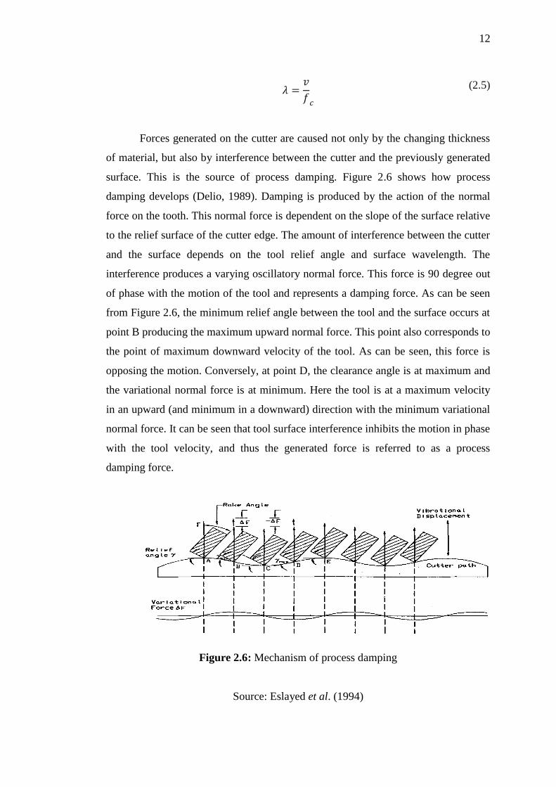
Forces generated on the cutter are caused not only by the changing thickness
of material, but also by interference between the cutter and the previously generated
surface. This is the source of process damping. Figure 2.6 shows how process
damping develops (Delio, 1989). Damping is produced by the action of the normal
force on the tooth. This normal force is dependent on the slope of the surface relative
to the relief surface of the cutter edge. The amount of interference between the cutter
and the surface depends on the tool relief angle and surface wavelength. The
interference produces a varying oscillatory normal force. This force is 90 degree out
of phase with the motion of the tool and represents a damping force. As can be seen
from Figure 2.6, the minimum relief angle between the tool and the surface occurs at
point B producing the maximum upward normal force. This point also corresponds to
the point of maximum downward velocity of the tool. As can be seen, this force is
opposing the motion. Conversely, at point D, the clearance angle is at maximum and
the variational normal force is at minimum. Here the tool is at a maximum velocity
in an upward (and minimum in a downward) direction with the minimum variational
normal force. It can be seen that tool surface interference inhibits the motion in phase
with the tool velocity, and thus the generated force is referred to as a process
damping force.
Figure 2.6: Mechanism of process damping
Source: Eslayed et al. (1994)
13
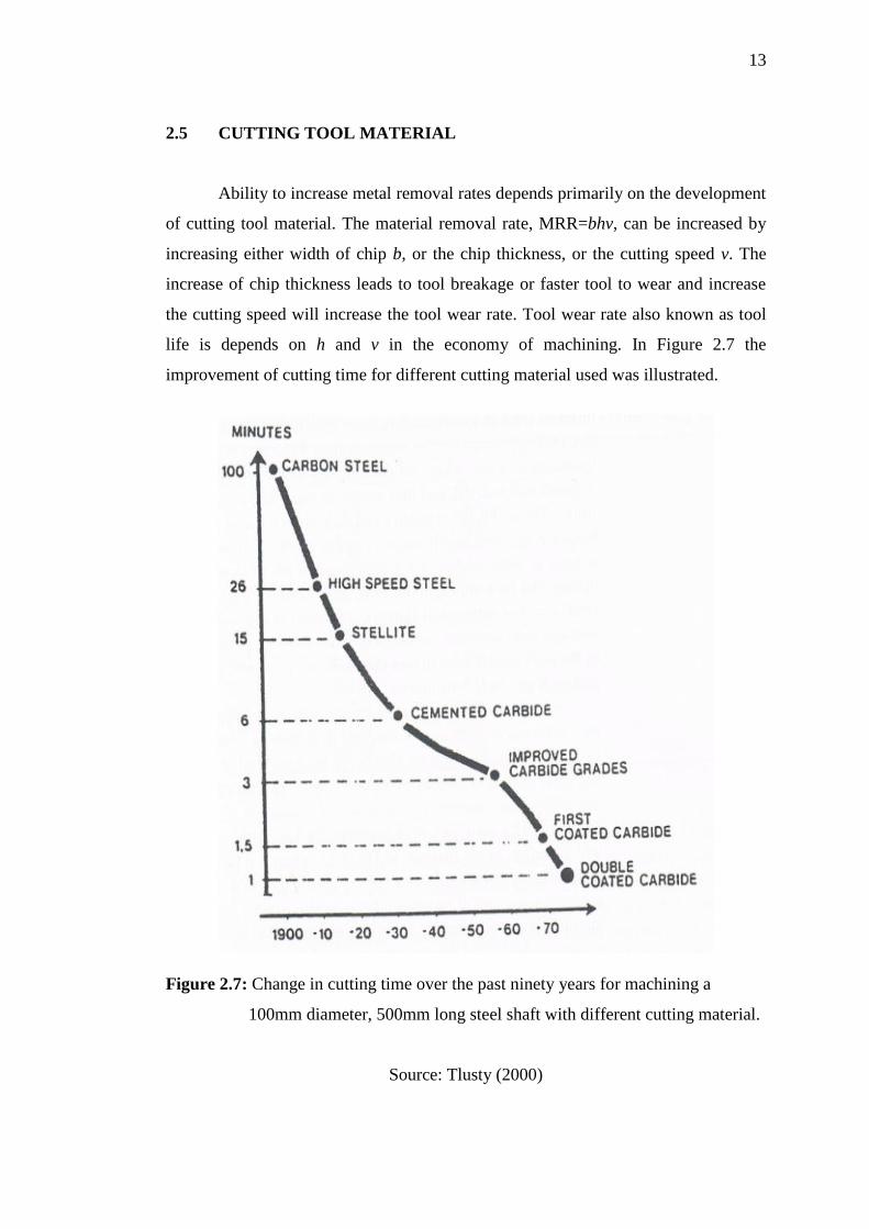
2.5 CUTTING TOOL MATERIAL
Ability to increase metal removal rates depends primarily on the development
of cutting tool material. The material removal rate, MRR=bhv, can be increased by
increasing either width of chip b, or the chip thickness, or the cutting speed v. The
increase of chip thickness leads to tool breakage or faster tool to wear and increase
the cutting speed will increase the tool wear rate. Tool wear rate also known as tool
life is depends on h and v in the economy of machining. In Figure 2.7 the
improvement of cutting time for different cutting material used was illustrated.
Figure 2.7: Change in cutting time over the past ninety years for machining a
100mm diameter, 500mm long steel shaft with different cutting material.
Source: Tlusty (2000)