¦ï* OÜ/@'qrð î¥ ×Ëîò=ÒL - ETSI · ETSI TS 101 377-5-1V1.1.1 (2001-03) Technical...
22
ETSI TS 101 377-5-1 V1.1.1 (2001-03) Technical Specification GEO-Mobile Radio Interface Specifications; Part 5: Radio interface physical layer specifications; Sub-part 1: Physical Layer on the Radio Path; GMR-2 05.001
Transcript of ¦ï* OÜ/@'qrð î¥ ×Ëîò=ÒL - ETSI · ETSI TS 101 377-5-1V1.1.1 (2001-03) Technical...
ETSI TS 101 377-5-1 V1.1.1 (2001-03)Technical Specification
GEO-Mobile Radio Interface Specifications;Part 5: Radio interface physical layer specifications;
Sub-part 1: Physical Layer on the Radio Path;GMR-2 05.001
ETSI
ETSI TS 101 377-5-1 V1.1.1 (2001-03)2GMR-2 05.001
ReferenceDTS/SES-002-05001
KeywordsGMR, GSM, GSO, interface, MES, mobile, MSS,
path, radio, satellite, S-PCN
ETSI
650 Route des LuciolesF-06921 Sophia Antipolis Cedex - FRANCE
Tel.: +33 4 92 94 42 00 Fax: +33 4 93 65 47 16
Siret N° 348 623 562 00017 - NAF 742 CAssociation à but non lucratif enregistrée à laSous-Préfecture de Grasse (06) N° 7803/88
Important notice
Individual copies of the present document can be downloaded from:http://www.etsi.org
The present document may be made available in more than one electronic version or in print. In any case of existing orperceived difference in contents between such versions, the reference version is the Portable Document Format (PDF).
In case of dispute, the reference shall be the printing on ETSI printers of the PDF version kept on a specific network drivewithin ETSI Secretariat.
Users of the present document should be aware that the document may be subject to revision or change of status.Information on the current status of this and other ETSI documents is available at http://www.etsi.org/tb/status/
If you find errors in the present document, send your comment to:[email protected]
Copyright Notification
No part may be reproduced except as authorized by written permission.The copyright and the foregoing restriction extend to reproduction in all media.
© European Telecommunications Standards Institute 2001.All rights reserved.
ETSI
ETSI TS 101 377-5-1 V1.1.1 (2001-03)3GMR-2 05.001
Contents
Intellectual Property Rights ..........................................................................................................................4
Foreword......................................................................................................................................................6
Introduction..................................................................................................................................................7
1 Scope..................................................................................................................................................8
2 References ..........................................................................................................................................8
3 Abbreviations .....................................................................................................................................9
4 Set of channels....................................................................................................................................94.1 Satellite Traffic Channels (S-TCH).............................................................................................................. 94.1.1 Speech Traffic Channel.......................................................................................................................... 94.1.2 Data Traffic Channels .......................................................................................................................... 104.2 Satellite Control Channels (S-CCH)........................................................................................................... 104.2.1 Satellite Broadcast Control Channel (S-BCCH) .................................................................................... 104.2.2 Satellite Common Control Channel (S-CCCH) ..................................................................................... 104.2.3 Satellite Dedicated Control Channels.................................................................................................... 104.2.3.1 Satellite Standalone Dedicated Control Channel (S-SDCCH)........................................................... 114.2.3.2 Satellite Associated Control Channel (S-ACCH) ............................................................................. 11
5 Reference configuration....................................................................................................................12
6 Block structures ................................................................................................................................13
7 Multiple access and timeslot structure...............................................................................................137.1 Hyperframes, superframes and multiframes ............................................................................................... 147.2 Timeslots and Bursts ................................................................................................................................. 157.3 Channel Organization................................................................................................................................ 15
8 Coding and interleaving ....................................................................................................................16
9 Modulation .......................................................................................................................................18
10 Transmission and reception...............................................................................................................18
11 Other Layer 1 Functions ...................................................................................................................19
Annex A (informative): Reference configuration.............................................................................20
Annex B (informative): Relations between specifications................................................................21
History .......................................................................................................................................................22
ETSI
ETSI TS 101 377-5-1 V1.1.1 (2001-03)4GMR-2 05.001
Intellectual Property RightsThe information pertaining to essential IPRs is publicly available for ETSI members and non-members, and can befound in ETSI SR 000 314: "Intellectual Property Rights (IPRs); Essential, or potentially Essential, IPRs notified toETSI in respect of ETSI standards", which is available from the ETSI Secretariat. Latest updates are available on theETSI Web server (http://www.etsi.org/ipr).
The attention of ETSI has been drawn to the Intellectual Property Rights (IPRs) listed below which are, or may be, ormay become, Essential to the present document. The IPR owner has undertaken to grant irrevocable licences, on fair,reasonable and non-discriminatory terms and conditions under these IPRs pursuant to the ETSI IPR Policy. Furtherdetails pertaining to these IPRs can be obtained directly from the IPR owner.
The present IPR information has been submitted to ETSI and pursuant to the ETSI IPR Policy, no investigation,including IPR searches, has been carried out by ETSI. No guarantee can be given as to the existence of other IPRs notreferenced in ETSI SR 000 314 (or the updates on the ETSI Web server) which are, or may be, or may become,essential to the present document.
IPRs:
Project Company Title Country ofOrigin
Patent n° CountriesApplicable
TS 101 377 V1.1.1 Digital VoiceSystems Inc
US US 5,715,365 US
TS 101 377 V1.1.1 Digital VoiceSystems Inc
US US 5,754,974 US
TS 101 377 V1.1.1 Digital VoiceSystems Inc
US US 5,226,084 US
TS 101 377 V1.1.1 Digital VoiceSystems Inc
US US 5,701,390 US
TS 101 377 V1.1.1 Digital VoiceSystems Inc
US US 5,826,222 US
IPR Owner: Digital Voice Systems IncOne Van de Graaff Drive Burlington,MA 01803USA
Contact: John C. HardwickTel.: +1 781 270 1030Fax: +1 781 270 0166
Project Company Title Country ofOrigin
Patent n° CountriesApplicable
TS 101 377 V1.1.1 Ericsson MobileCommunication
Improvements in, or in relationto, equalisers
GB GB 2 215 567 GB
TS 101 377 V1.1.1 Ericsson MobileCommunication
Power Booster GB GB 2 251 768 GB
TS 101 377 V1.1.1 Ericsson MobileCommunication
Receiver Gain GB GB 2 233 846 GB
TS 101 377 V1.1.1 Ericsson MobileCommunication
Transmitter Power Control forRadio Telephone System
GB GB 2 233 517 GB
IPR Owner: Ericsson Mobile Communications (UK) LimitedThe Keytech Centre, Ashwood WayBasingstokeHampshire RG23 8BGUnited Kingdom
Contact: John WatsonTel.: +44 1256 864 821

ETSI
ETSI TS 101 377-5-1 V1.1.1 (2001-03)5GMR-2 05.001
Project Company Title Country ofOrigin
Patent n° CountriesApplicable
TS 101 377 V1.1.1 Hughes NetworkSystems
US Pending US
IPR Owner: Hughes Network Systems11717 Exploration LaneGermantown, Maryland 20876USA
Contact: John T. WhelanTel: +1 301 428 7172Fax: +1 301 428 2802
Project Company Title Country ofOrigin
Patent n° CountriesApplicable
TS 101 377 V1.1.1 Lockheed MartinGlobalTelecommunic. Inc
2.4-to-3 KBPS Rate AdaptationApparatus for Use inNarrowband Data andFacsimile CommunicationSystems
US US 6,108,348 US
TS 101 377 V1.1.1 Lockheed MartinGlobalTelecommunic. Inc
Cellular Spacecraft TDMACommunications System withCall Interrupt Coding Systemfor Maximizing TrafficThroughputCellular SpacecraftTDMA CommunicationsSystem with Call InterruptCoding System for MaximizingTraffic Throughput
US US 5,717,686 US
TS 101 377 V1.1.1 Lockheed MartinGlobalTelecommunic. Inc
Enhanced Access Burst forRandom Access Channels inTDMA Mobile Satellite System
US US 5,875,182
TS 101 377 V1.1.1 Lockheed MartinGlobalTelecommunic. Inc
Spacecraft CellularCommunication System
US US 5,974,314 US
TS 101 377 V1.1.1 Lockheed MartinGlobalTelecommunic. Inc
Spacecraft CellularCommunication System
US US 5,974,315 US
TS 101 377 V1.1.1 Lockheed MartinGlobalTelecommunic. Inc
Spacecraft CellularCommunication System withMutual Offset High-arginForward Control Signals
US US 6,072,985 US
TS 101 377 V1.1.1 Lockheed MartinGlobalTelecommunic. Inc
Spacecraft CellularCommunication System withSpot Beam Pairing forReduced Updates
US US 6,118,998 US
IPR Owner: Lockheed Martin Global Telecommunications, Inc.900 Forge RoadNorristown, PA. 19403USA
Contact: R.F. FrancioseTel.: +1 610 354 2535Fax: +1 610 354 7244
ETSI
ETSI TS 101 377-5-1 V1.1.1 (2001-03)6GMR-2 05.001
ForewordThis Technical Specification (TS) has been produced by ETSI Technical Committee Satellite Earth Stations andSystems (SES).
The contents of the present document are subject to continuing work within TC-SES and may change following formalTC-SES approval. Should TC-SES modify the contents of the present document it will then be republished by ETSIwith an identifying change of release date and an increase in version number as follows:
Version 1.m.n
where:
- the third digit (n) is incremented when editorial only changes have been incorporated in the specification;
- the second digit (m) is incremented for all other types of changes, i.e. technical enhancements, corrections,updates, etc.
The present document is part 5, sub-part 1 of a multi-part deliverable covering the GEO-Mobile Radio InterfaceSpecifications, as identified below:
Part 1: "General specifications";
Part 2: "Service specifications";
Part 3: "Network specifications";
Part 4: "Radio interface protocol specifications";
Part 5: "Radio interface physical layer specifications";
Sub-part 1: "Physical Layer on the Radio Path; GMR-2 05.001";
Sub-part 2: "Multiplexing and Multiple Access on the Radio Path; GMR-2 05.002";
Sub-part 3: "Channel Coding; GMR-2 05.003";
Sub-part 4: "Modulation; GMR-2 05.004";
Sub-part 5: "Radio Transmission and Reception; GMR-2 05.005";
Sub-part 6: "Radio Subsystem Link Control; GMR-2 05.008";
Sub-part 7: "Radio Subsystem Synchronization; GMR-2 05.010";
Part 6: "Speech coding specifications".

ETSI
ETSI TS 101 377-5-1 V1.1.1 (2001-03)7GMR-2 05.001
IntroductionGMR stands for GEO (Geostationary Earth Orbit) Mobile Radio interface, which is used for mobile satellite services(MSS) utilizing geostationary satellite(s). GMR is derived from the terrestrial digital cellular standard GSM andsupports access to GSM core networks.
Due to the differences between terrestrial and satellite channels, some modifications to the GSM standard are necessary.Some GSM specifications are directly applicable, whereas others are applicable with modifications. Similarly, someGSM specifications do not apply, while some GMR specifications have no corresponding GSM specification.
Since GMR is derived from GSM, the organization of the GMR specifications closely follows that of GSM. The GMRnumbers have been designed to correspond to the GSM numbering system. All GMR specifications are allocated aunique GMR number as follows:
GMR-n xx.zyy
where:
- xx.0yy (z = 0) is used for GMR specifications that have a corresponding GSM specification. In this case, thenumbers xx and yy correspond to the GSM numbering scheme.
- xx.2yy (z = 2) is used for GMR specifications that do not correspond to a GSM specification. In this case,only the number xx corresponds to the GSM numbering scheme and the number yy is allocated by GMR.
- n denotes the first (n = 1) or second (n = 2) family of GMR specifications.
A GMR system is defined by the combination of a family of GMR specifications and GSM specifications as follows:
• If a GMR specification exists it takes precedence over the corresponding GSM specification (if any). Thisprecedence rule applies to any references in the corresponding GSM specifications.
NOTE: Any references to GSM specifications within the GMR specifications are not subject to this precedencerule. For example, a GMR specification may contain specific references to the corresponding GSMspecification.
• If a GMR specification does not exist, the corresponding GSM specification may or may not apply. Theapplicability of the GSM specifications is defined in GMR-n 01.201.
ETSI
ETSI TS 101 377-5-1 V1.1.1 (2001-03)8GMR-2 05.001
1 ScopeThe present document is an introduction to the 05-series of the GMR-2 technical specifications for the system. Itconsists of a general description of the organization of the physical layer with reference to the technical specificationswhere each part is specified in detail. It introduces furthermore, the reference configuration that will be used throughoutthis series of technical specifications.
Operating frequencies for the GMR-2 Ground Terminal (Gateway or NCC) -to-Satellite Terminal (ST) uplink/downlinkare not specified, however, for ease of understanding, the present document describes the requirements for a GMR-2Ground Terminal-to-Satellite Terminal uplink/downlink operating in the 3 000 MHz/6 000 MHz C-Band.
2 ReferencesThe following documents contain provisions which, through reference in this text, constitute provisions of the presentdocument.
• References are either specific (identified by date of publication and/or edition number or version number) ornon-specific.
• For a specific reference, subsequent revisions do not apply.
• For a non-specific reference, the latest version applies.
[1] GMR-2 01.004 (ETSI TS 101 377-1-1): "GEO-Mobile Radio Interface Specifications;Part 1: General specifications; Sub-part 1: Abbreviations and Acronyms; GMR-2 01.004".
[2] GMR-2 03.003 (ETSI TS 101 377-3-3): "GEO-Mobile Radio Interface Specifications;Part 3: Network specifications; Sub-part 3: Numbering, Addressing and Identification; GMR-203.003".
[3] GMR-2 03.020 (ETSI TS 101 377-3-10): "GEO-Mobile Radio Interface Specifications;Part 3: Network specifications; Sub-part 10: Security related Network Functions; GMR-2 03.020".
[4] GMR-2 03.022 (ETSI TS 101 377-3-11): "GEO-Mobile Radio Interface Specifications;Part 3: Network specifications; Sub-part 11: Functions Related to Mobile Earth Station (MES) inidle Mode; GMR-2 03.022".
[5] GMR-2 04.003 (ETSI TS 101 377-4-2): "GEO-Mobile Radio Interface Specifications;Part 4: Radio interface protocol specifications; Sub-part 2: GMR-2 Mobile Earth Station-NetworkInterface; Channel Structures and Access capabilities; GMR-2 04.003".
[6] GMR-2 04.008 (ETSI TS 101 377-4-7): "GEO-Mobile Radio Interface Specifications;Part 4: Radio interface protocol specifications; Sub-part 7: Mobile radio interface Layer 3Specifications; GMR-2 04.008".
[7] GMR-2 04.021 (ETSI TS 101 377-4-10): "GEO-Mobile Radio Interface Specifications;Part 4: Radio interface protocol specifications; Sub-part 10: Rate Adaptation on the Mobile earthStation (MES)- Gateway System Interface. GMR-2 04.021".
[8] GMR-2 05.002 (ETSI TS 101 377-5-2): "GEO-Mobile Radio Interface Specifications;Part 5: Radio interface physical layer specifications; Sub-part 2: Multiplexing and Multiple Accesson the Radio Path; GMR-2 05.002".
[9] GMR-2 05.003 (ETSI TS 101 377-5-3): "GEO-Mobile Radio Interface Specifications;Part 5: Radio interface physical layer specifications; Sub-part 3: Channel Coding. GMR-2 05.003".
[10] GMR-2 05.004 (ETSI TS 101 377-5-4): "GEO-Mobile Radio Interface Specifications;Part 5: Radio interface physical layer specifications; Sub-part 4: Modulation; GMR-2 05.004".

ETSI
ETSI TS 101 377-5-1 V1.1.1 (2001-03)9GMR-2 05.001
[11] GMR-2 05.005 (ETSI TS 101 377-5-5): "GEO-Mobile Radio Interface Specifications;Part 5: Radio interface physical layer specifications; Sub-part 5: Radio Transmission andReception; GMR-2 05.005".
[12] GMR-2 05.008 (ETSI TS 101 377-5-6): "GEO-Mobile Radio Interface Specifications;Part 5: Radio interface physical layer specifications; Sub-part 6: Radio Subsystem Link Control;GMR-2 05.008".
[13] GMR-2 05.010 (ETSI TS 101 377-5-7): "GEO-Mobile Radio Interface Specifications;Part 5: Radio interface physical layer specifications; Sub-part 7: Radio SubsystemSynchronization; GMR-2 05.010".
[14] ANSI/IEEE Std. 149-1979: "Standard Test Procedure for Antennas".
3 AbbreviationsFor the purposes of the present document, the abbreviations given in GMR-2 01.004 [1] apply.
4 Set of channelsThe radio subsystem provides a certain number of logical channels that can be separated into two categories accordingto GMR-2 04.003 [5]:
Satellite Traffic Channels (S-TCH) and Satellite Control Channels (S-CCH).
4.1 Satellite Traffic Channels (S-TCH)The Satellite Traffic Channels (S-TCH) are intended to carry two types of user information streams: encoded speechand data. Four types of Satellite mode traffic channels are defined:
a) Full Rate Traffic Channel (S-TCH/F). This channel carries information at a gross rate of 24 kbps.
b) Half Rate Traffic Channel (S-TCH/H). This channel carries information at a gross rate of 12 kbps.
c) Quarter Rate Traffic Channel (S-TCH/Q). This channel carries information at a gross rate of 6 kbps.
d) Eighth Rate Traffic Channel (S-TCH/E). This channel carries information at a gross rate of 3 kbps.
For the purpose of this series of technical specifications, the specific traffic channel available in the categories of speechand user data are defined in the following clauses:
4.1.1 Speech Traffic Channel
The following traffic channels are defined to carry encoded speech:
a) Satellite half-rate traffic channel for enhanced speech (S-TCH/HES);
b) Satellite half-rate traffic channel for robust speech (S-TCH/HRS);
c) Satellite quarter-rate traffic channel for basic speech (S-TCH/QBS);
d) Satellite eighth-rate traffic channel for low-rate speech (S-TCH/ELS).
NOTE: The full-rate traffic channel defined in GSM is not used for speech over the satellite.

ETSI
ETSI TS 101 377-5-1 V1.1.1 (2001-03)10GMR-2 05.001
4.1.2 Data Traffic Channels
The following traffic channels are defined to carry user data:
a) Satellite full-rate traffic channel for 9,6 kbps user data (S-TCH/F9.6);
b) Satellite half-rate traffic channel for 4,8 kbps user data (S-TCH/H4.8);
c) Satellite half-rate robust traffic channel for 2,4 kbps user data (S-TCH/HR2.4);
d) Satellite quarter-rate traffic channel for 2,4 kbps user data (S-TCH/Q2.4).
NOTE: The eighth-rate traffic channel, as defined above for speech, is not used for data over the satellite.
4.2 Satellite Control Channels (S-CCH)The Signalling Channels can be sub-divided into:
a) S-BCCH (Satellite Broadcast Control Channel);
b) S-CCCH (Satellite Common Control Channel);
c) S-DCCH (Satellite Dedicated Control Channel).
Satellite dedicated control channels include standalone and associated control channels. An associated control channelis always allocated in conjunction with a S-TCH. Two types of ACCH are defined: continuous stream (slow ACCH orS-SACCH) and burst stealing mode (fast ACCH or S-FACCH). For the purpose of this series of technicalspecifications, the satellite signalling channels are distinguished in the following clauses.
4.2.1 Satellite Broadcast Control Channel (S-BCCH)
The following satellite broadcast control channels are provided:
a) Satellite Synchronization Channel (S-SCH);
b) Satellite Broadcast Control Channel (S-BCCH);
c) Satellite High Margin Synchronization Channel (S-HMSCH));
d) Satellite High Margin Broadcast Control Channel (S-HBCCH);
e) Satellite Beam Broadcast Channel (S-BBCH) (Option currently not supported by GMR-2 system).
4.2.2 Satellite Common Control Channel (S-CCCH)
The following satellite common control channels are provided:
a) Satellite High Penetration Alerting Channel (S-HPACH);
b) Satellite Paging Channel (S-PCH);
c) Satellite Random Access Channel (S-RACH);
d) Satellite Access Grant Channel (S-AGCH);
e) Satellite Robust Paging Channel (S-PCH/R) (Currently not supported by GMR-2 system);
f) Satellite Robust Access Grant Channel (S-AGCH/R) (Currently not supported by GMR-2 system).
4.2.3 Satellite Dedicated Control Channels
The dedicated control channels include two types: standalone dedicated and associated control channels. These typesare defined in the following clauses.

ETSI
ETSI TS 101 377-5-1 V1.1.1 (2001-03)11GMR-2 05.001
4.2.3.1 Satellite Standalone Dedicated Control Channel (S-SDCCH)
a) Satellite Half Rate Robust Standalone Dedicated Control Channel (S-SDCCH/HR).
b) Satellite Quarter Rate Standalone Dedicated Control Channel (S-SDCCH/Q).
c) Satellite Eighth Rate Standalone Dedicated Control Channel (S-SDCCH/E).
4.2.3.2 Satellite Associated Control Channel (S-ACCH)
The associated control channels are divided into two groups Fast Associated and Slow Associated:
Fast Associated Control Channels:
a) Satellite S-TCH/HRS Fast Associated Control Channel (S-FACCH/HRS);
b) Satellite S-TCH/HES Fast Associated Control Channel (S-FACCH/HES);
c) Satellite S-TCH/QBS Fast Associated Control Channel (S-FACCH/QBS);
d) Satellite S-TCH/ELS Fast associated Control Channel (S-FACCH/ELS);
e) Satellite S-TCH/Q2.4 Fast Associated Control Channel (S-FACCH/Q2.4);
f) Satellite S-TCH/HR2.4 Fast Associated Control Channel (S-FACCH/HR2.4);
g) Satellite S-TCH/H4.8 Fast Associated Control Channel (S-FACCH/H4.8);
h Satellite S-TCH/F9.6 Fast associated Control Channel (S-FACCH/F9.6).
Slow Associated Control Channels:
a) Satellite Slow, S-TCH/F Associated Control Channel (S-SACCH/TF);
b) Satellite Slow, S-TCH/H Associated Control Channel (S-SACCH/TH);
c) Satellite Slow, S-TCH/HR Associated Control Channel (S-SACCH/THR);
d) Satellite Slow, S-SDCCH/HR Associated Control Channel (S-SACCH/CHR);
e) Satellite Slow, S-SDCCH/Q Associated Control Channel (S-SACCH/CQ);
f) Satellite Slow, S-TCH/Q Associated Control Channel (S-SACCH/TQ);
g) Satellite Slow, S-TCH/E Associated Control Channel (S-SACCH/TE);
h) Satellite Slow, S-SDCCH/E Associated Control Channel (S-SACCH/CE).
The logical channels mentioned above are mapped on physical channels that are described in this set of technicalspecifications. The different physical channels provide for the transmission of information pertaining to higher layersaccording to a block structure.

ETSI
ETSI TS 101 377-5-1 V1.1.1 (2001-03)12GMR-2 05.001
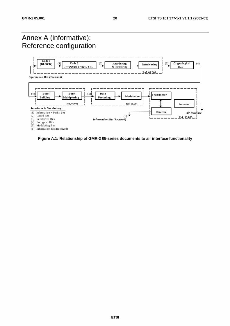
5 Reference configurationFor the purpose of elaborating the physical layer specification, a reference configuration of the transmission chain isused as shown in annex A. This reference configuration also indicates which parts are dealt with in details in whichtechnical specification. It shall be noted that only the transmission part is specified, the receiver being specified only viathe overall performance requirements. With reference to this configuration, the technical specifications in the 05-seriesaddress the following functional units:
1) GMR-2 05.002 [8]: Multiplexing and multiple access on the radio path;
2) GMR-2 05.003 [9]: Channel coding;
3) GMR-2 05.004 [10]: Modulation;
4) GMR-2 05.005 [11]: Radio transmission and reception.
This reference configuration defines also a number of points of vocabulary in relation to the name of bits at differentlevels in the configuration. It must be outlined, in the case of the encrypted bits, that they are named only with respect totheir position after the encryption unit, and not to the fact that they pertain to a flow of information that is actuallyencrypted.
ETSI
ETSI TS 101 377-5-1 V1.1.1 (2001-03)13GMR-2 05.001
6 Block structuresTable 6.1: Channel block structures
Type of Channel Net Bit Rate(kbit/s)
Block Length (bits) Block Recurrence(ms)
(S-TCH/HES) Reserved Reserved Reserved(S-TCH/HRS) 3,6 72 20(S-TCH/QBS) 3,6 72 20(S-TCH/ELS) Reserved Reserved Reserved(S-TCH/F9.6) Reserved Reserved Reserved(S-TCH/H4.8) Reserved Reserved Reserved
(S-TCH/HR2.4) (Note 2) 3 30 10(S-TCH/Q2.4) 3 30 10
(S-SDCCH/HR) Reserved Reserved Reserved(S-SDCCH/Q) Reserved Reserved Reserved(S-SDCCH/E) 0,766 6 184 240
(S-FACCH/HES) Reserved Reserved Reserved(S-FACCH/HRS) 1,533 3 184 120
(S-FACCH/HR2.4) (Note 2) 1,533 3 184 120(S-FACCH/QBS) 1,533 3 184 120(S-FACCH/Q2.4) 1,533 3 184 120(S-FACCH/ELS) Reserved Reserved Reserved(S-FACCH/H4.8) Reserved Reserved Reserved(S-FACCH/F9.6) Reserved Reserved Reserved(S-SACCH/TF) 0,383 3 184 480(S-SACCH/TH) 0,383 3 184 480
(S-SACCH/THR) 0,383 3 184 480(S-SACCH/TQ) 0,191 7 184 960(S-SACCH/TE) 0,095 83 184 1 920
(S-SACCH/CHR) Reserved Reserved Reserved(S-SACCH/CQ) Reserved Reserved Reserved(S-SACCH/CE) 0,095 83 184 1 920
(S-BCCH) 0,390 8 184 6 120/13(S-HBCCH) 0,015 3 194 165 240/13(S-HMSCH) 0,314 4 148 6 120/13(S-RACH) r × 0,059 5 (Note 1) 28 61 20/13(S-PCH) n × 0,390 8 (Note 1) 184 6 120/13
(S-AGCH) p × 0,390 8 (Note 1) 184 6 120/13(S-HPACH) (IMSI) 0,112 6 53 6 120/13
(S-HPACH) (TMSI) (Note 2) 0,063 7 30 6 120/13(S-SCH) 0,053 1 25 6 120/13
(S-BBCH) (Note 2) 0,007 24 184 330 480/13(S-PCH/R) Reserved Reserved Reserved
(S-AGCH/R) Reserved Reserved ReservedNOTE 1: n, p, and r refer to the total number of blocks per recurrence period.NOTE 2: Implementation of this channel is optional.
7 Multiple access and timeslot structureThe access scheme is a combination of Frequency Division Multiple Access (FDMA) and Time Division MultipleAccess (TDMA) with eight in the forward direction or two in the return direction full rate physical channels per carrier.The carrier separation is 200 kHz in the forward direction and 50 kHz in the return. A physical channel is thereforedefined as a sequence of TDMA frames, a time slot number, and an FDMA carrier frequency.
In the forward direction the basic radio resource is a time slot lasting ≈ 576,9 µs (15/26 ms) and transmittinginformation at a modulation (burst) rate of ≈ 270,833 kbit/s (1625/6 kbit/s). In the return direction the basic radioresource is a time slot lasting ≈ 2,3 ms (60/26 ms) and transmitting information at a modulation rate of ≈ 67,708 kbit/s(1 625/24 kbit/s). The time slot duration, including guard time, is 156,25 bit durations.
ETSI
ETSI TS 101 377-5-1 V1.1.1 (2001-03)14GMR-2 05.001
We shall describe successively the time frame structures, the time slot structures and the channel organization. Theappropriate specifications will be found in GMR-2 05.002 [8] (Multiplexing and Multiple Access).
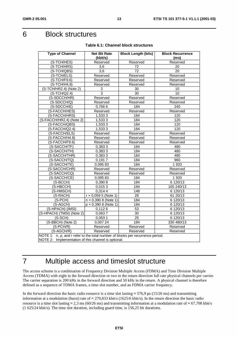
7.1 Hyperframes, superframes and multiframesA diagrammatic representation of all the time frame structures is shown in figure 7.1.1. The longest recurrent timeperiod of the structure is called hyperframe and has a duration of 3h 28 min 53 sec 760 ms (or 12 533,76 sec). TheTDMA frames are numbered modulo this hyperframe (TDMA frame number, or FN, from 0 to 2 715 647). This longperiod is needed to support cryptographic mechanisms defined in GMR-2 03.020 [3].
One hyperframe is subdivided in 2 048 superframes which have a duration of 6,12 seconds. The superframe is the leastcommon multiple of the time frame structures. The superframe is itself subdivided into multiframes: two types ofmultiframes exist in the system:
1) A 26-frame multiframe (51 per superframe) with a duration of 120 ms, comprising 26 TDMA frames. Thismultiframe is used to carry S-TCH (and S-SACCH/T), S-FACCH and S-SDCCH (and S-SACCH/C);
2) A 51-frame multiframe (26 per superframe) with a duration of ≈ 235,4 ms (3 060/13 ms), comprising 51 TDMAframes. This multiframe is used to carry S-BCCH, S-AGCH, S-PCH, S-RACH, S-HPACH, S-HBCCH,S-HMSCH, S-AGCH/R, S-PCH/R, S-BBCH, and S-SCH.
A TDMA frame, comprising eight time slots has a duration of ≈ 4,62 ms (60/13 ms).
0 1 2 3 4 5 6 2 042 2 043 2 0442 045 2 046 2 047
1 hyperframe = 2 048 superframes = 2 715 648 TDMA frames (3h 28mn 53s 760ms)
1 superframe = 1 326 TDMA frames (6,12 s)(= 51 (26-frame) multiframes or 26 (51-frame) multiframes)
0 1 2 3 47 48 49 500 1 24 25
0 1 2 3 4 22 23 24 25
1 (26-frame) multiframe = 26 TDMA frames (120 ms) 1 multiframe = 51 TDMA frames (3 060/13ms)
0 1 2 3 46 47 48 49 50
0 1 2 3 4 5 6 7
Return: 1 TDMA frame = 2 time slots (120/26 or 4,615 ms)
TB3
Encrypted bits60
Training Sequence22
Encrypted bits60
TB3
GP8,25
TB3
TB3
GP8,25
TB3
Encoded bits39
Synchronization Sequence64
Encoded bits39
TB3
GP8,25
Normal Burst156,25 Bits
Extended Guard Bits1-8 Return Frame Periods
Normal Burst (NB)
High Margin Burst (HB)
Synchronization Burst (SB)
Access Burst (AB)
(TB: Tail bits - GP: Guard period)
1 time slot = 156,25 bit durations (15/26 or 60/26 msec)(1 bit duration = 48/13 or 192/13 us)
1 2
Forward: 1 TDMA frame = 8 time slots (120/26 or 4,615 ms)
14-bit IDEncoded bits
64Encoded bits
64
FTCB Burst156,25 Bits
Figure 7.1.1: Timeframe Structure and Bursts
ETSI
ETSI TS 101 377-5-1 V1.1.1 (2001-03)15GMR-2 05.001
7.2 Timeslots and BurstsThe time slot is a time interval of ≈ 576,9 µs (15/26 ms), that is 156,25 bit durations, and its physical content is called a"burst". The burst rate in the forward direction is ≈ 270,833 kbit/s (1 625/6 kbit/s) and is ≈ 67,708 kbit/s(1 625/24 kbit/s) for the return. Six different types of bursts exist in the system:
1) Normal burst (NB): this burst is used to carry information on traffic and some control channels. It contains twopackets of 60 bits data surrounding a 22 bit training (synchronization) sequence. Three tail bits are added to eachside and include a guard time of 8,25 bit durations (≈ 30,46 µs).
2) Synchronization Burst (SB): this burst is used for time synchronization of the mobile. It contains a long trainingsequence and carries the information of the TDMA frame number (FN) and Gateway Identity Code. It containstwo packets of 39 bits data surrounding a 64 bit training (synchronization) sequence. Three tail bits are added toeach side and includes a guard time of 8,25 bit durations. The repetition of synchronization bursts is also namedsynchronization channel (S-SCH).
3) Access Burst (AB): this burst is used for random access by the Mobile Earth Station (MES). It is actuallycomposed of two bursts: the Normal burst (item 1.) and the Frequency and Time Correction burst (item 6). Italso contains an extended guard period of up to 16 return time slots (i.e., 8 return frame periods).
4) High Margin Burst (HB): this burst is used to carry the information of either the S-HPACH or the S-HBCCH. Itconsists of two 64 bit information packets surrounding a 14 bit midamble. Three tail bits are added to each sideand includes a guard time of 8,25 bit durations.
5) High Margin Burst (HB) or M-Sequence Burst (HDB or HMB): this burst is used to carry a known pattern ofbits for the S-HMSCH. It consists of 148 bits based on a defined pattern (either a dotting sequence or an M-sequence) and a guard time of 8,25 bit durations.
6) Frequency and Time Correction Burst (FTCB): This burst is used for the initial new channel transmission fromboth the MES and the Gateway.
A diagram of these bursts appears in figure 7.1.1. The HDB, HMB, and FTCB bursts correspond to a sequence of a142-bit designated bit pattern, surrounded by 3 tail bits on either side, and with an 8,25 bit guard band.
NOTE: For additional information on High Margin Burst (HB) and M-Sequence Burst (HDB or HMB) refer tothe figures in GMR-2 05.002 [8] clauses 7.2.9 and 7.2.10 respectively.
7.3 Channel OrganizationThe channel organization for the S-TCH's, S-SDCCH's, S-FACCH's, S-SACCH/C's, and S-SACCH/T's uses a 26-frameMultiframe and is 120 ms in duration. Twenty-four of these TDMA frames are used for traffic and two are used for in-band signalling (S-SACCH). The S-FACCH is transmitted by preempting information bits of the S-TCH bursts thatsupport speech (see GMR-2 05.003 [9]).
The Multiframe for the control channels is 3 060/13 ms in duration and consists of 51 TDMA frames. A TDMA framefor both Traffic and Control is 120/26 ms in duration.
In the forward direction the TDMA frame consists of 8 time slots (burst periods). In the return, it consists of two timeslots. It is organized as described in GMR-2 05.002 [8].
ETSI
ETSI TS 101 377-5-1 V1.1.1 (2001-03)16GMR-2 05.001
8 Coding and interleavingA brief description of the coding schemes that are used for the logical channels mentioned in clause 4 is provided intable 6.1. For these channels the following operations are performed:
1) external coding (block coding);
2) internal coding (convolutional coding);
3) interleaving.
Coding for the basic voice channel (S-TCH/QBS) is based on a rate 1/2, 64-state punctured convolutional code withgenerator polynomials, as specified in GMR-2 05.003 [9]. Coding for the robust voice channel (S-TCH/HRS) is basedon a rate 1/4, 64-state punctured convolutional code with generator polynomials, as specified in GMR-2 05.003 [9]. Theassociated and dedicated signalling channels (S-SACCH, S-FACCH, and S-SDCCH) are coded with a rate 1/2, 64-stateconvolutional code along with a Fire Code with generator polynomials, as specified in GMR-2 05.003 [9]. Robustversions of these channels use a 1/4-rate code. The data (and fax) channels (S-TCH/Q2.4) are coded with a rate 1/2,64-state convolutional code with generator polynomials, as specified in GMR-2 05.003 [9]. Robust versions of thesechannels (S-TCH/HR2.4) use a 1/4-rate code.
The information bits in the other control channels (S-BCCH, S-AGCH, S-PCH) are coded with a rate 1/2, 16-stateConvolutional code and a Fire Code with generator polynomials, as specified in GMR-2 05.003 [9]. The S-SCHchannel is coded with a rate 1/2, 16-state Convolutional code, as specified in GMR-2 05.003 [9]. The S-RACH channelis coded with a rate 1/3, 64-state Convolutional Code, as specified in GMR-2 05.002 [8]. The S-HPACH and S-HBCCHchannel are coded with a rate 1/2, 16-state Convolutional code, and a Walsh code, as specified in GMR-2 05.003 [9].
Interleaving dimensions for the communications channels are indicated in table 8.1.

ETSI
ETSI TS 101 377-5-1 V1.1.1 (2001-03)17GMR-2 05.001
Table 8.1: Coding and interleaving
Type of Channel Bits/Block Data +Parity + Tail
Convolutional CodeRate
Coded Bits PerBlock
Interleaving Depth
(S-TCH/HES) Reserved Reserved Reserved Reserved(S-TCH/HRS)Class I & IIClass III
78(12 + 33) + (6 + 0) + 0
27 + 0 + 01/4 (w/ 18 punc)
Repeat
24018654
6 Bursts
(S-TCH/QBS)Class I & IIClass III
78(12 + 33) + (6 + 0) + 0
27 + 0 + 01/2 (w/ 9 punc)
-
1209327
3 Bursts
(S-TCH/ELS) Reserved Reserved Reserved Reserved(S-TCH/F9.6) Reserved Reserved Reserved Reserved(S-TCH/H4.8) Reserved Reserved Reserved Reserved(S-TCH/HR2.4) (Note) 8 × 30 + 0 + 6 1/4 (w/ 24 punc) 960 22 Bursts(S-TCH/Q2.4) 8 × 30 + 0 + 6 1/2 (w/ 12 punc) 480 11 Bursts(S-SDCCH/HR) Reserved Reserved Reserved Reserved(S-SDCCH/Q) Reserved Reserved Reserved Reserved(S-SDCCH/E) 184 + 40 + 4 × 6 1/2 w/ 4 punc 480 4 Bursts(S-FACCH/HES) Reserved Reserved Reserved Reserved(S-FACCH/HRS) 184 + 40 + 4 × 6 1/4 (w/ 8 punc) 960 12 Bursts(S-FACCH/HR2.4) (Note) 184 + 40 + 4 × 6 1/2 (w/ 8 punc) 960 22 Bursts(S-FACCH/QBS) 184 + 40 + 4 × 6 1/2 (w/ 4 punc) 480 6 Bursts(S-FACCH/Q2.4) 184 + 40 + 4 × 6 1/2 (w/ 4 punc) 480 11 Bursts(S-FACCH/ELS) Reserved Reserved Reserved Reserved(S-FACCH/H4.8) Reserved Reserved Reserved Reserved(S-FACCH/F9.6) Reserved Reserved Reserved Reserved(S-SACCH/TF) 184 + 40 + 4 × 6 1/2 w/ 4 punc 480 4 Bursts(S-SACCH/TH) 184 + 40 + 4 × 6 1/2 w/ 4 punc 480 4 Bursts(S-SACCH/THR) 184 + 40 + 4 × 6 1/4 w/ 8 punc 960 8 Bursts(S-SACCH/TQ) 184 + 40 + 4 × 6 1/2 w/ 4 punc 480 4 Bursts(S-SACCH/TE) 184 + 40 + 4 × 6 1/2 w/ 4 punc 480 4 Bursts(S-SACCH/CHR) Reserved Reserved Reserved Reserved(S-SACCH/CQ) Reserved Reserved Reserved Reserved(S-SACCH/CE) 184 + 40 + 6 1/2 480 4 Bursts(S-BCCH) 184 + 40 + 4 1/2 456 4 Bursts(S-HBCCH) 194
10 + 4184 + 40
4 × (56 + 6 + 4)
1/2 & Walsh
1/2 & Walsh
28/7 × 128
4 × [(133/7) × 128]
81 Bursts4 Bursts
4 × 19 Bursts(S-RACH) 28 + 6 + 6 1/3 120 N/A(S-PCH) 184 + 40 + 4 1/2 456 4 Bursts(S-AGCH) 184 + 40 + 4 1/2 456 4 Bursts(S-HPACH) (IMSI) 53 + 5 + 0
10 + 448 + 4
1/2 & Walsh1/2 & Walsh
133/7 × 12828/7 × 128105/7 × 128
19 Bursts4 Bursts15 Bursts
(S-HPACH) (TMSI) (Note) 30 + 4 + 010 + 424 + 4
1/2 & Walsh1/2 & Walsh
133/7 × 12828/7 × 12856/7 × 128
12 Bursts4 Bursts8 Bursts
(S-SCH) 25 + 10 + 4 1/2 78 N/A(S-BBCH) (Note) Refer to
GMR-2 05.00 [9]Refer to
GMR-2 05.003 [9]Refer to
GMR-2 05.003 [9]Refer to
GMR-2 05.003 [9](S-PCH/R) Reserved Reserved Reserved Reserved(S-AGCH/R) Reserved Reserved Reserved ReservedNOTE: Implementation of this channel is optional
ETSI
ETSI TS 101 377-5-1 V1.1.1 (2001-03)18GMR-2 05.001
9 ModulationIn the forward direction (Ground Station-to-MES) the modulation is filtered OQPSK (Offset Quadrature Phase ShiftKeying). The filtering characteristic is a square root raised cosine with a rolloff of 0,35. In the return direction(MESto-Ground Station) the modulation is GMSK (Gaussian Minimum Shift Keying) with a BT of 0,3. GMSK isprecoded in the same manner as specified in standard GSM. In single hop MES-to-MES links, MESs will transmitGMSK as in the case of MES-to-Ground Station modulation. In single hop MES-to-MES links, the MESs will receiveGMSK for the S-TCH and S-FACCH as in the case of MES-to-Ground Station modulation, and OQPSK for theS-SACCH as in the case of Ground Station-to-MES modulation.
As mentioned previously the modulation rate is ≈ 270,83 kbit/s (1 625/6 kbit/s) in the forward direction (MES receive)and ≈ 67,708 kbit/s (1 625/24 kbit/s) in the return (MES transmit). This scheme is specified in detail inGMR-2 05.004 [10] (Modulation and Demodulation).
10 Transmission and receptionThe modulated stream is then transmitted on a radio frequency carrier. The frequency bands and channel arrangementare as follows:
L-band Frequencies: Forward D/L: 1 525,0 MHz to 1 559,0 MHz Right Hand Circular Polarization, as definedby ANSI/IEEE Std. 149-1979 [14]Return U/L: 1 626,5 MHz to 1 660,5 MHz Right Hand Circular Polarization, as defined byANSI/IEEE Std. 149-1979 [14]
C-band Frequencies: Forward U/L: 6 425,0 MHz to 6 725,0 MHz Linear Horizontal Polarization, as defined byANSI/IEEE Std. 149-1979 [14]Return D/L: 3 400,0 to 3 700,0 MHz Linear Vertical Polarization, as defined by IEEE Std.149-1979 [14]
The carrier spacing is 200 kHz on the forward link. The carrier spacing is 50 kHz on the return link.
The carrier frequency is designated by the absolute radio frequency channel number (ARFCN) defined as nL for the L-Band channels and can be defined as nC for feeder link operation at C-Band. In addition, for the return links thedefinition of the carrier frequency also requires specification of the TN (Time slot Number). Therefore, if we call Fl(n)the frequency of the carrier n in the lower band, Fu(n) the corresponding frequency value in the upper band, and FO thefrequency offset, we have:
a) L-Band User-Satellite Links:FlL(nL) = 1 525,1 + nL × 0,2 for 0 < nL < 169, FO = 0FlL(nL) = 1 525,1 + nL × 0,2 + 0,075 for 0 < nL < 168, FO = 1FuL(nL,TN) = FlL(nL) + 101,425 + (TN modulo 4) × 0,05
b) As an example, for C-Band Ground-Satellite Links:FuC(nc) = 6 425,1 + nc × 0,2 for 0 < nc < 1 499FlC(nc,k) = FuC(nC) - 3 025,075 + (TN modulo 4) × 0,05
Frequencies are in MHz.
The output powers for each transmitter and the corresponding G/T at each receiver is specified in GMR-2 05.005 [11].
The specific RF channels, together with the requirements on the transmitter and the receiver will be found inGMR-2 05.005 [11] (Transmission and Reception). The requirements on the overall transmission quality together withthe measurement conditions are also in GMR-2 05.005 [11].
ETSI
ETSI TS 101 377-5-1 V1.1.1 (2001-03)19GMR-2 05.001
11 Other Layer 1 FunctionsThe transmission involves other functions. These functions may necessitate the handling of specific protocols betweenthe Gateway and MES. Relevant topics for these cases are:
1) The power control mechanisms which adjust the output level of the Mobile Earth Station (and of the Gateway) inorder to ensure that the required quality is achieved with the least possible radiated power. Power levels withsteps have been defined for that purpose as described in GMR-2 05.008 [12] (Radio Subsystem Link Control)and GMR-2 05.005 [11] (Transmission and Reception).
2) The synchronization of the receiver with regards to frequency and time (time acquisition and time framealignment). The synchronization problems are described in GMR-2 05.010 [13] (Synchronization Aspects).
3) The measurements and sub-procedures used in the first selection or reselection of a satellite spotbeam by a MESare specified in GMR-2 05.008 [12] (Radio Subsystem Link Control). The overall selection and reselectionprocedures, together with the idle mode activities of a mobile are defined in GMR-2 03.022 [4] (FunctionsRelated to MES in Idle Mode).
ETSI
ETSI TS 101 377-5-1 V1.1.1 (2001-03)20GMR-2 05.001
Annex A (informative):Reference configuration
Code 1(BLOCK) Code 2
(CONVOLUTIONAL)Reordering
& PuncturingInterleaving Cryptological
Unit
Ref. 05.003
Information Bits (Transmit)
BurstBuilding
BurstMultiplexing
DataPrecoding Modulation
Transmitter
Receiver
AntennaRef. 05.002 Ref. 05.004
Ref. 05.005
Air Interface
Information Bits (Received)
(1) (2) (3) (4)
(4) (5)
(6)
Interfaces & Vocabulary
(1) Information + Parity Bits(2) Coded Bits(3) Interleaved Bits(4) Encrypted Bits(5) Modulating Bits(6) Information Bits (received)
Figure A.1: Relationship of GMR-2 05-series documents to air interface functionality

ETSI
ETSI TS 101 377-5-1 V1.1.1 (2001-03)21GMR-2 05.001
Annex B (informative):Relations between specifications
Layer 3 protocols04.007 & 04.008
Layer 2 protocols04.005 & 04.006
Encryption03.020
ChannelCoder/Decoder/Interleaver
05.003
SpeechCoder/Decoder
06.001
Link Control
03.022 & 05.008
Layer 1 Protocols04.004
MultiplexingMultiple Access
05.002Modulation
05.004
Transmitterand Receiver
05.005
Synchronization05.010
To All Blocks
Figure B.1: Relationship of GMR-2 05-series documents to other air interface
ETSI
ETSI TS 101 377-5-1 V1.1.1 (2001-03)22GMR-2 05.001
History
Document history
V1.1.1 March 2001 Publication


![ETSI Plugtests Test Plan V1.0.0 (2017-02) · ... Architectural Framework". [NFV003] ETSI GS NFV 003: ... Interface and Information Model Specification". [IFA006] ETSI GS NFV-IFA 006:](https://static.fdocuments.in/doc/165x107/5b22cf767f8b9ac4748b456b/etsi-plugtests-test-plan-v100-2017-02-architectural-framework-nfv003.jpg)