I N S T A L L A T I O N / O P E R A T I O N M A N U A L M O D E L L A 4 0 0€¦ · ·...
44
I N S T A L L A T I O N / O P E R A T I O N M A N U A L MODEL LA400 MEDIUM DUTY SWING GATE OPERATOR Serial # Primary Arm Serial # Secondary Arm Serial # Control Box Installation Date 2 YEAR WARRANTY Radio Receiver Built on Board 315MHz
Transcript of I N S T A L L A T I O N / O P E R A T I O N M A N U A L M O D E L L A 4 0 0€¦ · ·...

I N S T A L L A T I O N / O P E R A T I O N M A N U A L
M O D E L L A 4 0 0M E D I U M D U T Y S W I N G G A T E O P E R A T O R
Serial # Primary Arm
Serial # Secondary Arm
Serial # Control Box
Installation Date
2 Y E A R W A R R A N T Y
Radio ReceiverBuilt on Board
315MHz

Loop Inputs . . . . . . . . . . . . . . . . . . . . . . . . . . . . . . . . . . . . . . . .31Photo/Edge Inputs (P6-7-8 and 9) . . . . . . . . . . . . . . . . . . . . . . .32Safety Accessories for Secondary Entrapment Protection . . . . .33
Operation 34Reset Button . . . . . . . . . . . . . . . . . . . . . . . . . . . . . . . . . . . . . . .34Remote Control . . . . . . . . . . . . . . . . . . . . . . . . . . . . . . . . . . . . .34Manual Release . . . . . . . . . . . . . . . . . . . . . . . . . . . . . . . . . . . . .34
Maintenance 35-36Battery Replacement . . . . . . . . . . . . . . . . . . . . . . . . . . . . . . . . .36
Basic Control Board Layout 37Wiring Diagram 38Troubleshooting 39-40Repair Parts 41-42LA400 Swing Gate Accessories 43Warranty Policy and Service 44
When you see these Safety Symbols and Signal Words on thefollowing pages, they will alert you to the possibility of seriousinjury or death if you do not comply with the warnings thataccompany them. The hazard may come from somethingmechanical or from electric shock. Read the warnings carefully.When you see this Signal Word on the following pages, it willalert you to the possibility of damage to your gate and/or the gateoperator if you do not comply with the cautionary statements thataccompany it. Read them carefully.
Mechanical
Electrical
ATTENTION
AVERTISSEMENT AVERTISSEMENT
AVERTISSEMENT
WARNINGWARNING
CAUTION
WARNING
WARNING
PRECAUCIÓN ADVERTENCIA
ADVERTENCIAADVERTENCIA
ATTENTION
AVERTISSEMENT AVERTISSEMENT
AVERTISSEMENT
WARNING
CAUTIONCAUTION
WARNING
WARNING
PRECAUCIÓN ADVERTENCIA
ADVERTENCIAADVERTENCIA
IMPORTANT NOTE• BEFORE attempting to install, operate or maintain the operator,
you must read and fully understand this manual and follow allsafety instructions.
• DO NOT attempt repair or service of your commercial door andgate operator unless you are an Authorized Service Technician.ATTENTION
AVERTISSEMENT AVERTISSEMENT
AVERTISSEMENT
WARNING
CAUTION
WARNINGWARNING
WARNING
PRECAUCIÓN ADVERTENCIA
ADVERTENCIAADVERTENCIA
TOOLS NEEDED FOR INSTALLATIONDuring assembly, installation and adjustment of the operator thetools listed below will be needed.• Wrench or Socket Set• Phillips Head Screwdriver• C Clamps• Level• Small Screwdriver• T25 Torx Head Screwdriver
TABLE OF CONTENTS
INTRODUCTION
Introduction 2-5Carton Inventory . . . . . . . . . . . . . . . . . . . . . . . . . . . . . . . . . . . . .3Additional Items Needed for Installation . . . . . . . . . . . . . . . . . . .3Operator Dimensions and Specifications . . . . . . . . . . . . . . . . . . .3UL325 Classifications . . . . . . . . . . . . . . . . . . . . . . . . . . . . . . . . . .4Safety Installation Information . . . . . . . . . . . . . . . . . . . . . . . . . . .5
Overview of Typical Installation 6-10Left-Hand Gate . . . . . . . . . . . . . . . . . . . . . . . . . . . . . . . . . . . . . . .6Right-Hand Gate . . . . . . . . . . . . . . . . . . . . . . . . . . . . . . . . . . . . . .6Dual Gate . . . . . . . . . . . . . . . . . . . . . . . . . . . . . . . . . . . . . . . . . . .7Safety Precautions for Swing and Ornamental “Grill Type Gates” . . . . . . . . . . . . . . . . . . . . . . . . . . .8Warning Sign Placement . . . . . . . . . . . . . . . . . . . . . . . . . . . . . . .8Before Installation Check Your Gate . . . . . . . . . . . . . . . . . . . . . . .9Mounting Options . . . . . . . . . . . . . . . . . . . . . . . . . . . . . . . . . . .10
Installation 11-18Step 1: Manual Release . . . . . . . . . . . . . . . . . . . . . . . . . . . . . . .11Step 2A: Determine Position of the Pull-to-Open Bracket . . . . .12Step 2B: Determine Position of the “Optional” Push-to-Open Bracket (Not Provided) . . . . . . . . . . . . . . . . . . . .12Step 3: Determine Mounting Location . . . . . . . . . . . . . . . . . . . .13Step 4: Assemble Gate Post Bracket (Pull-to-Open) . . . . . . . . . .13Step 5: Attach Bracket to Arm . . . . . . . . . . . . . . . . . . . . . . . . . .14Step 6: Position Operator on Gate . . . . . . . . . . . . . . . . . . . . . . .14Step 7: Test Gate Travel . . . . . . . . . . . . . . . . . . . . . . . . . . . . . . .15Step 8: Secure Gate Post Bracket to Gate Post . . . . . . . . . . . . .16Step 9: Secure Gate Bracket to Gate . . . . . . . . . . . . . . . . . . . . . .16Step 10: Warning Sign Placement . . . . . . . . . . . . . . . . . . . . . . .17Step 11: Open the Control Box . . . . . . . . . . . . . . . . . . . . . . . . . .18Step 12: Select Mounting Holes . . . . . . . . . . . . . . . . . . . . . . . . .18Step 13: Mount Control Box . . . . . . . . . . . . . . . . . . . . . . . . . . . .18
Motor Wiring 19-20Step 1: Watertight Connector Nut . . . . . . . . . . . . . . . . . . . . . . .19Step 2: Insert Operator Cable . . . . . . . . . . . . . . . . . . . . . . . . . . .19Step 3: Connect Operator to Control Board . . . . . . . . . . . . . . . .20
Power Wiring 21-22Connect Transformer to Control Board . . . . . . . . . . . . . . . . . . .21Earth Ground Rod Installation (Optional) . . . . . . . . . . . . . . . . . .22
Control Wiring 23Adjusting/Running the Operator 24-26Step 1: Set Dip Switch . . . . . . . . . . . . . . . . . . . . . . . . . . . . . . . .24Step 2: Program Limits . . . . . . . . . . . . . . . . . . . . . . . . . . . . . . .25Step 3: Set Force/Bi-part/Timer . . . . . . . . . . . . . . . . . . . . . . . . .26
Optional Control and Safety Device Wiring 27-33To Add or Reprogram a Remote Control . . . . . . . . . . . . . . . . . .27Dip Switch Settings . . . . . . . . . . . . . . . . . . . . . . . . . . . . . . . . . .28Wire Stop Button (Optional) . . . . . . . . . . . . . . . . . . . . . . . . . . . .29
2
3
HARDWARE KIT
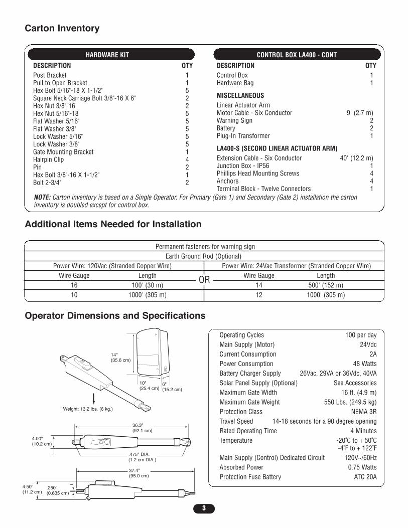
DESCRIPTION QTYPost Bracket 1Pull to Open Bracket 1Hex Bolt 5/16"-18 X 1-1/2" 5Square Neck Carriage Bolt 3/8"-16 X 6" 2Hex Nut 3/8"-16 2Hex Nut 5/16"-18 5Flat Washer 5/16" 5Flat Washer 3/8" 5Lock Washer 5/16" 5Lock Washer 3/8" 5Gate Mounting Bracket 1Hairpin Clip 4Pin 2Hex Bolt 3/8"-16 X 1-1/2" 1Bolt 2-3/4" 2
CONTROL BOX LA400 - CONT
DESCRIPTION QTYControl Box 1Hardware Bag 1
MISCELLANEOUSLinear Actuator ArmMotor Cable - Six Conductor 9' (2.7 m)Warning Sign 2Battery 2Plug-In Transformer 1
LA400-S (SECOND LINEAR ACTUATOR ARM)Extension Cable - Six Conductor 40' (12.2 m)Junction Box - IP56 1Phillips Head Mounting Screws 4Anchors 4Terminal Block - Twelve Connectors 1
NOTE: Carton inventory is based on a Single Operator. For Primary (Gate 1) and Secondary (Gate 2) installation the cartoninventory is doubled except for control box.
Operating Cycles 100 per dayMain Supply (Motor) 24VdcCurrent Consumption 2APower Consumption 48 WattsBattery Charger Supply 26Vac, 29VA or 36Vdc, 40VASolar Panel Supply (Optional) See AccessoriesMaximum Gate Width 16 ft. (4.9 m)Maximum Gate Weight 550 Lbs. (249.5 kg)Protection Class NEMA 3RTravel Speed 14-18 seconds for a 90 degree openingRated Operating Time 4 MinutesTemperature -20˚C to + 50˚C
-4˚F to + 122˚FMain Supply (Control) Dedicated Circuit 120V~/60HzAbsorbed Power 0.75 WattsProtection Fuse Battery ATC 20A
Permanent fasteners for warning signEarth Ground Rod (Optional)
Power Wire: 120Vac (Stranded Copper Wire) Power Wire: 24Vac Transformer (Stranded Copper Wire)Wire Gauge Length Wire Gauge Length
16 100' (30 m) 14 500' (152 m)10 1000' (305 m) 12 1000' (305 m)
OR
36.3"(92.1 cm)
.475" DIA.(1.2 cm DIA.)
4.50"(11.2 cm)
.250"(0.635 cm)
37.4"(95.0 cm)
4.00"(10.2 cm)
Weight: 13.2 lbs. (6 kg.)
Operator Dimensions and Specifications
Additional Items Needed for Installation
Carton Inventory
10"(25.4 cm)
14"(35.6 cm)
6"(15.2 cm)

4
UL325 Model ClassificationsThe LA400 is intended for use with vehicular swing gates. The operator can be used in Class I, Class II and Class III applications.
CLASS I – RESIDENTIAL VEHICULAR GATE OPERATORA vehicular gate operator (or system) intended for use in a home of one-to four single family dwelling, ora garage or parking area associated therewith.
CLASS II – COMMERCIAL/GENERAL ACCESS VEHICULAR GATE OPERATORA vehicular gate operator (or system) intended for use in a commercial location or building such as amulti-family housing unit (five or more single family units) hotel, garages, retail store or other buildingservicing the general public.
CLASS III – INDUSTRIAL/LIMITED ACCESS VEHICULAR GATE OPERATORA vehicular gate operator (or system) intended for use in a industrial location or building such as afactory or loading dock area or other locations not intended to service the general public.
SAFETY ACCESSORY SELECTIONAll UL325 compliant LiftMaster gate operators will accept externalentrapment protection devices to protect people from motorizedgate systems. UL325 requires that the type of entrapmentprotection correctly matches each gate application. Below are thefour types of entrapment protection systems recognized byUL325 for use on this operator.
ENTRAPMENT PROTECTION TYPESType A: Inherent obstruction sensing system, self-contained
within the operator. This system must sense and initiatethe reverse of the gate within two seconds of contactwith a solid object.
Type B1: Connections provided for a non-contact device, such as a photoelectric eye can be used as a secondaryprotection.
Type B2: Connections provided for a contact sensor. A contactdevice such as a gate edge can be used for secondaryprotection.
Type E: Built-in audio alarm. Examples include sirens, horns or buzzers.
NOTE: UL requires that all installations musthave warning signs placed in plain view onboth sides of the gate to warn pedestrians ofthe dangers of motorized gate systems.
UL325 ENTRAPMENT PROTECTIONREQUIREMENTS
The chart above illustrates the entrapment protectionrequirements for each of the three UL325 classes.In order to complete a proper installation you must satisfy theentrapment protection chart shown above. That means thatthe installation must have one primary means of entrapmentprotection and one independent secondary means ofentrapment protection. Both primary and secondaryentrapment protection methods must be designed, arrangedor configured to protect against entrapments in both the openand close directions of gate travel.For Example: For a slide gate system that is installed on a single-family residence (UL325 Class I) you must provide thefollowing: As your primary type of entrapment protection youmust provide Type A inherent (built into the operator)entrapment sensing and at least one of the following as yoursecondary entrapment protection: Type B1- Non-contactsensors such as photoelectric eyes, Type B2- Contact sensorssuch as gate edges.
Primary Type
ClassI and II
Class III A, B1 or B2 A, B1,B2 or E
A, B1 orB2A
UL325 Swing and Gate BarrierInstallation (Arm) Operator
Secondary Type
Moving Gate Can CauseInjury or Death
KEEP CLEAR! Gate may move at anytime without prior warning.
Do not let children operate the gate orplay in the gate area.This entrance is for vehicles only.Pedestrians must use separate entrance
Gate Operator Entrapment Protection
Class

5
Safety Installation Information1. Vehicular gate systems provide convenience and security. Gate systems are comprised of many component parts. The gate operator is only
one component. Each gate system is specifically designed for an individual application.2. Gate operating system designers, installers and users must take into account the possible hazards associated with each individual application.
Improperly designed, installed or maintained systems can create risks for the user as well as the bystander. Gate systems design andinstallation must reduce public exposure to potential hazards.
3. A gate operator can create high levels of force in its function as a component part of a gate system. Therefore, safety features must beincorporated into every design. Specific safety features include:• Gate Edges • Guards for Exposed Rollers • Photoelectric Sensors• Screen Mesh • Vertical Posts • Instructional and Precautionary Signage
4. Install the gate operator only when:a. The operator is appropriate for the construction and the usage class of the gate.b. All openings of a horizontal slide gate are guarded or screened from the bottom of the gate to a minimum of 4' (1.2 m) above the ground to
prevent a 2-1/4" (6 cm) diameter sphere from passing through the openings anywhere in the gate, and in that portion of the adjacent fencethat the gate covers in the open position.
c. All exposed pinch points are eliminated or guarded, and guarding is supplied for exposed rollers.5. The operator is intended for installation only on gates used for vehicles. Pedestrians must be supplied with a separate access opening. The
pedestrian access opening shall be designed to promote pedestrian usage. Locate the gate such that persons will not come in contact with thevehicular gate during the entire path of travel of the vehicular gate.
6. The gate must be installed in a location so that enough clearance is supplied between the gate and adjacent structures when opening andclosing to reduce the risk of entrapment. Swinging gates shall not open into public access areas.
7. The gate must be properly installed and work freely in both directions prior to the installation of the gate operator.8. Controls intended for user activation must be located at least six feet (6') away from any moving part of the gate and where the user is
prevented from reaching over, under, around or through the gate to operate the controls. Outdoor or easily accessible controls shall have asecurity feature to prevent unauthorized use.
9. The Stop and/or Reset (if provided separately) must be located in the line-of-sight of the gate. Activation of the reset control shall not cause theoperator to start.
10. A minimum of two (2) WARNING SIGNS shall be installed, one on each side of the gate where easily visible.11. For a gate operator utilizing a non-contact sensor:
a. Reference owner’s manual regarding placement of non-contact sensor for each type of application.b. Care shall be exercised to reduce the risk of nuisance tripping, such as when a vehicle trips the sensor while the gate is still moving.c. One or more non-contact sensors shall be located where the risk of entrapment or obstruction exists, such as the perimeter reachable by a
moving gate or barrier.12. For a gate operator utilizing a contact sensor such as an edge sensor:
a. One or more contact sensors shall be located where the risk of entrapment or obstruction exists, such as at the leading edge, trailing edgeand post mounted both inside and outside of a vehicular horizontal slide gate.
b. One or more contact sensors shall be located at the bottom edge of a vehicular vertical lift gate.c. A hard wired contact sensor shall be located and its wiring arranged so the communication between the sensor and the gate operator is not
subject to mechanical damage.d. A wireless contact sensor such as the one that transmits radio frequency (RF) signals to the gate operator for entrapment protection
functions shall be located where the transmission of the signals are not obstructed or impeded by building structures, natural landscaping orsimilar obstruction. A wireless contact sensor shall function under the intended end-use conditions.
e. One or more contact sensors shall be located on the inside and outside leading edge of a swing gate. Additionally, if the bottom edge of aswing gate is greater than 6" (152 mm) above the ground at any point in its arc of travel, one or more contact sensors shall be located onthe bottom edge.
f. One or more contact sensors shall be located at the bottom edge of a vertical barrier (arm).

6
Outside Property
Inside Property
Direction of
Gate ravel
Moving Gate Can Cause
Injury or Death
KEEP CLEAR! Gate may move at any
time without prior warning.
Do not let children operate the gate or
play in the gate area.
This entrance is for vehicles only
Pedestrians must use separate entrance
T
Moving Gate Can Cause
Injury or Death
KEEP CLEAR! Gate may move at any
time without prior warning.
Do not let children operate the gate or
play in the gate area.
This entrance is for vehicles only
Pedestrians must use separate entrance
OVERVIEW OF TYPICALINSTALLATION
NOTE: One or more non-contact sensors shall be located where the risk of entrapment or obstruction exists at either theopening or closing direction. Care shall be exercised to reduce the risk of nuisance tripping, such as when a vehicle, tripsthe sensor while the gate is still moving.
To prevent SERIOUS INJURY or DEATH; one or more non-contact sensors shall be located where the risk ofentrapment or obstruction exists.
ATTENTION
AVERTISSEMENT AVERTISSEMENT
AVERTISSEMENT
WARNINGWARNING
CAUTION
WARNING
WARNING
PRECAUCIÓN ADVERTENCIA
ADVERTENCIAADVERTENCIA
Control Boxwith Batteries
Antenna
Warning Sign
Hinge
Post Bracket
Operator
Gate Bracket
Entrapment Sensors
Power Cable
PVC Conduit (not provided) toprotect the power cable and lowvoltage wire from lawn mowersand string trimmers.
Left-Hand Gate
Right-Hand GateWarning Sign
Hinge
Antenna
Control Boxwith Batteries
Power Cable
Operator
Post Bracket
PVC Conduit (not provided) toprotect the power cable andlow voltage wire from lawnmowers and string trimmers.
Gate Bracket
Entrapment Sensors

7
Outside Property
Inside Property
Moving Gate Can Cause
Injury or Death
KEEP CLEAR! Gate may move at any
time without prior warning.
Do not let children operate the gate or
play in the gate area.
This entrance is for vehicles only
Pedestrians must use separate entrance
Direction of
Gate 1 ravel
T
Direction of
Gate 2 ravel
T
Dual Gate Typical Installation
Entrapment Sensors
Entrapment Sensors
Warning Sign
Control Boxwith Batteries
Antenna
Hinge
Post Bracket
Power Cable
PVC Conduit (not provided) toprotect the power cable andlow voltage wire from lawnmowers and string trimmers.
Gate Bracket
Gate 1
Gate 2
Junction Box
Extension Cable

8
Moving Gate Can CauseInjury or Death
KEEP CLEAR! Gate may move at anytime without prior warning.
Do not let children operate the gate orplay in the gate area.This entrance is for vehicles only.Pedestrians must use separate entrance
To prevent SERIOUS INJURY or DEATH from a moving gate:• Install warning signs on EACH side of gate in PLAIN VIEW.• Permanently secure each warning sign in a suitable manner
using fastening holes.
ATTENTION
AVERTISSEMENT AVERTISSEMENT
AVERTISSEMENT
WARNINGWARNING
CAUTION
WARNING
WARNING
PRECAUCIÓN ADVERTENCIA
ADVERTENCIAADVERTENCIA
To prevent SERIOUS INJURY or DEATH from a moving gate:• Entrapment protection devices MUST be installed to protect
anyone who may come near a moving gate.• Locate entrapment protection devices to protect in BOTH the
open and close gate cycles.• Locate entrapment protection devices to protect between
moving gate and RIGID objects, such as posts.• A swinging gate shall NOT open into public access ways.
ATTENTION
AVERTISSEMENT AVERTISSEMENT
AVERTISSEMENT
WARNINGWARNING
CAUTION
WARNING
WARNING
PRECAUCIÓN ADVERTENCIA
ADVERTENCIAADVERTENCIA
Warning Sign Placement
Safety Precautions for Swing and Ornamental “Grill Type Gates”
9
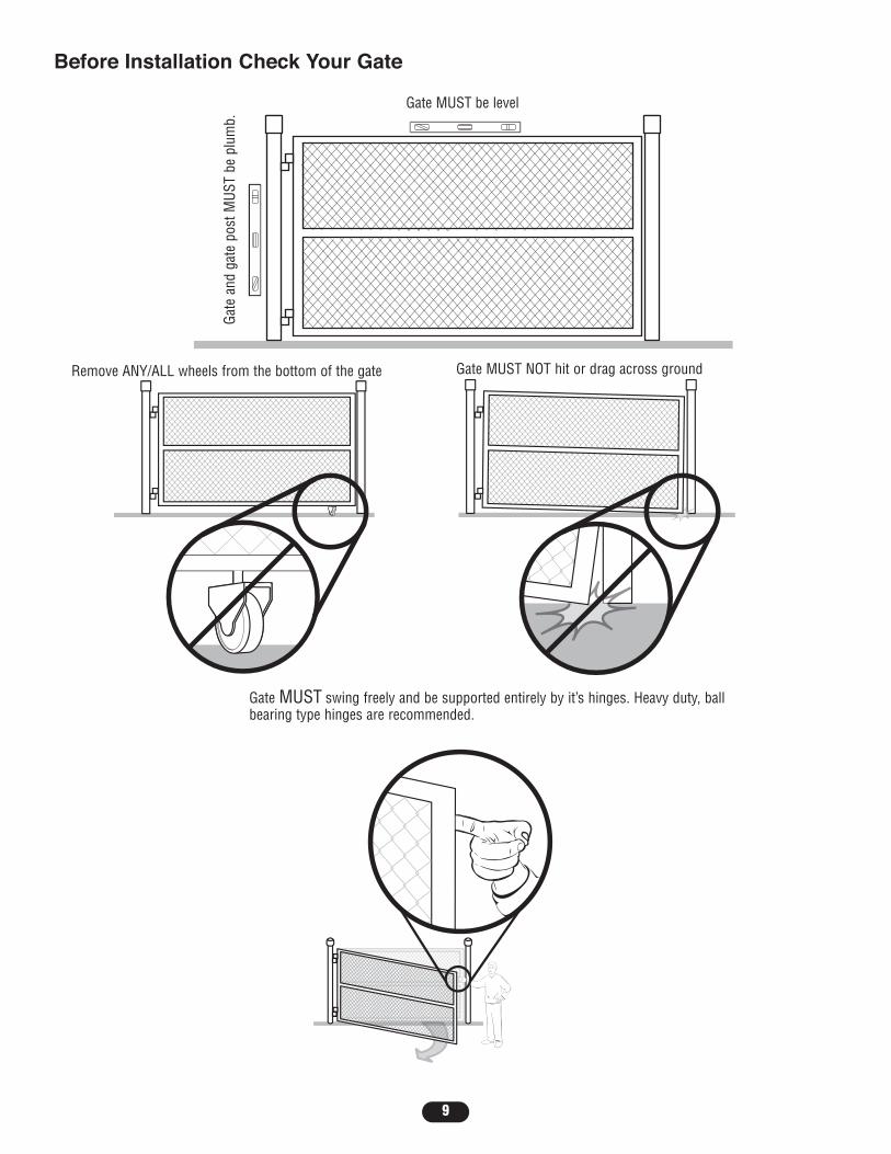
Before Installation Check Your Gate
Gate MUST swing freely and be supported entirely by it’s hinges. Heavy duty, ballbearing type hinges are recommended.
Remove ANY/ALL wheels from the bottom of the gate Gate MUST NOT hit or drag across ground
Gate MUST be level
Gate
and
gat
e po
st M
UST
be p
lum
b.

10
Mounting OptionsMounting locations vary depending on type and style of your gate. Minimum distance from the ground should not be lessthan 4" from the bottom of the gate operator arm.
Recommended:= Gate post bracket mounting locations = Gate bracket mount locations
Optional:= Gate post bracket mounting locations = Gate bracket mount locations

INSTALLATION
11
Step 1: Manual ReleaseInsert the key into the lock and turn counter-clockwise 180°. Turn the release lever counter-clockwise 180°. The operator isin manual mode.
Release Lever

12
Step 2A: Determine Position of the Pull-to-Open BracketThe Pull-To-Open bracket can be assembled to work on a Left-Hand or a Right-Hand gate. Review the gate types belowand select the type of installation you will require.NOTE: If the Pull-To-Open bracket is not assembled correctly you will damage the operator.
Step 2B: Determine Position of the “Optional” Push-to-Open Bracket (Not provided. See Accessories.)The Push-To-Open bracket can be assembled to work on a Left-Hand or a Right-Hand gate. Review the gate types belowand select the type of installation you will require.
Right-Hand GateLeft-Hand Gate
Right-Hand GateLeft-Hand Gate
Left-Hand Gate Right-Hand Gate
Right-Hand GateLeft-Hand Gate
13
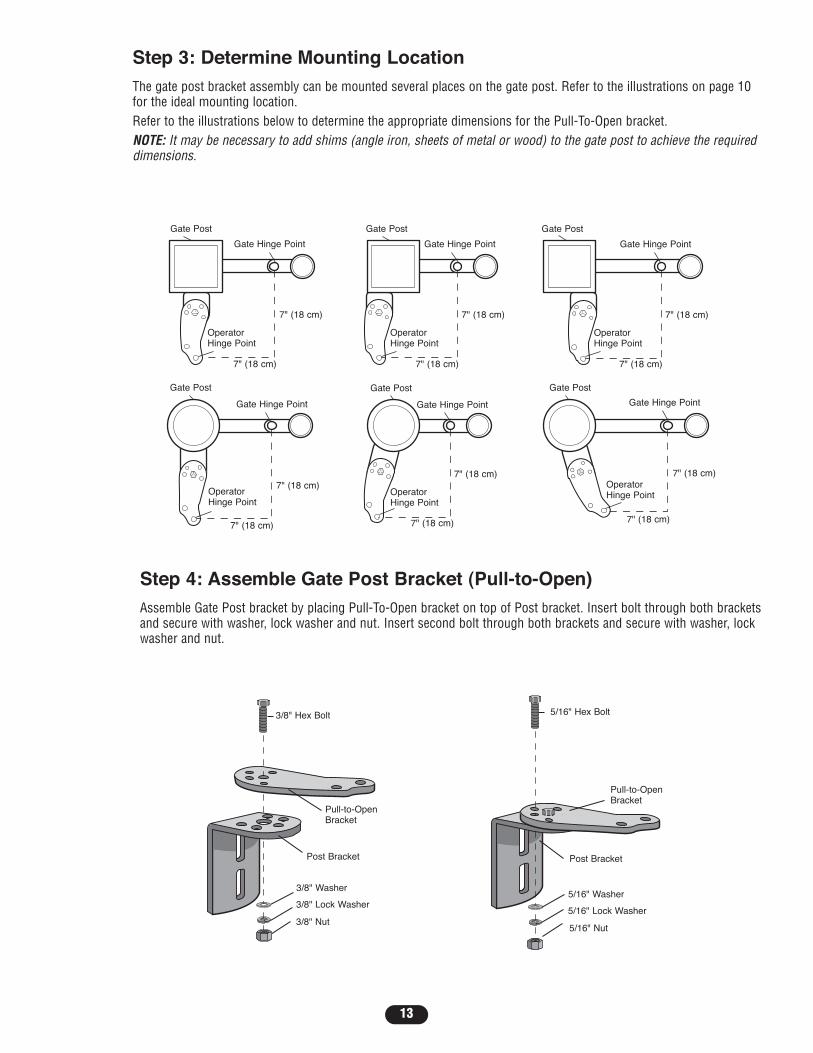
Step 4: Assemble Gate Post Bracket (Pull-to-Open)Assemble Gate Post bracket by placing Pull-To-Open bracket on top of Post bracket. Insert bolt through both bracketsand secure with washer, lock washer and nut. Insert second bolt through both brackets and secure with washer, lockwasher and nut.
3/8" Hex Bolt
Pull-to-Open Bracket
Post Bracket
3/8" Washer
3/8" Lock Washer
3/8" Nut
Pull-to-Open Bracket
5/16" Hex Bolt
Post Bracket
5/16" Washer
5/16" Lock Washer
5/16" Nut
Step 3: Determine Mounting LocationThe gate post bracket assembly can be mounted several places on the gate post. Refer to the illustrations on page 10for the ideal mounting location.Refer to the illustrations below to determine the appropriate dimensions for the Pull-To-Open bracket.NOTE: It may be necessary to add shims (angle iron, sheets of metal or wood) to the gate post to achieve the requireddimensions.
Gate Post
Gate Hinge Point
7" (18 cm)
OperatorHinge Point
7" (18 cm)
Gate Post
Gate Hinge Point
7" (18 cm)
OperatorHinge Point
7" (18 cm)
Gate Post
Gate Hinge Point
7" (18 cm)
OperatorHinge Point
7" (18 cm)
Gate Post
Gate Hinge Point
7" (18 cm)OperatorHinge Point
7" (18 cm)
Gate Post
Gate Hinge Point
7" (18 cm)
OperatorHinge Point
7" (18 cm)
Gate Post
Gate Hinge Point
7" (18 cm)OperatorHinge Point
7" (18 cm)

14
NOTE: All the illustrations on the following pages display a typical Left-Hand Gate installation.
Step 5: Attach Brackets to ArmAttach gate post bracket to arm using hex bolt and lock nut with nylon insert. Attach gate bracket to arm using pin andhairpin clip.
Step 6: Position Operator on GateThe gate post bracket assembly can be mounted several places on the gate post. Refer to the illustrations on page 10for mounting options.Place opener arm against gate post at the desired vertical position and temporarily secure Gate Post bracket with C-clamp. Arm must be level.
Open gate to desired open position (no greater than 100°) and hold arm against gate. Mark mounting holes on gatefor reference.Temporarily secure the gate bracket using a C-clamp.
Hex Bolt
Gate PostBracket
Pin
Gate Bracket
HairpinClip
HairpinClip

15
NOTE: If gate does not open and close completely adjust the position of the gate bracket and mark new mounting holes.
Ensure that the arm does not bind against the pull-to-open bracket.
Step 7: Test Gate TravelManually open and close the gate.
Ensure that the piston does not bottom out.
Do not allow piston to fully extendor fully retract.
1/2" (1.3 cm)
1/2" (1.3 cm)
16
OR
OR
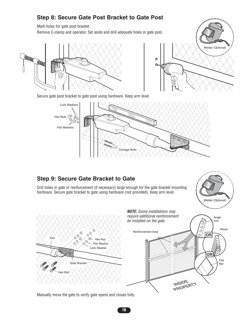
Step 8: Secure Gate Post Bracket to Gate PostMark holes for gate post bracket.Remove C-clamp and operator. Set aside and drill adequate holes in gate post.
Secure gate post bracket to gate post using hardware. Keep arm level.
Step 9: Secure Gate Bracket to GateDrill holes in gate or reinforcement (if necessary) large enough for the gate bracket mountinghardware. Secure gate bracket to gate using hardware (not provided). Keep arm level.
NOTE: Some installations mayrequire additional reinforcementbe installed on the gate.
Manually move the gate to verify gate opens and closes fully.
Carriage Bolts
Lock Washers
Hex Nuts
Flat Washers
Hex Nut
Flat Washer
Lock Washer
Gate Bracket
Hex Bolt
Arm
AngleIron
Wood
FlatBar
Reinforcement Area
Welder (Optional)
Welder (Optional)
17
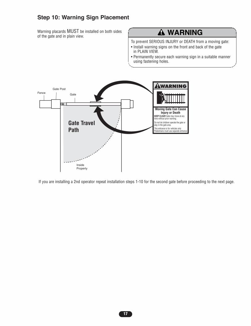
If you are installing a 2nd operator repeat installation steps 1-10 for the second gate before proceeding to the next page.
Step 10: Warning Sign Placement
Moving Gate Can CauseInjury or Death
KEEP CLEAR! Gate may move at anytime without prior warning.
Do not let children operate the gate orplay in the gate area.This entrance is for vehicles onlyPedestrians must use separate entrance
Warning placards MUST be installed on both sidesof the gate and in plain view.
To prevent SERIOUS INJURY or DEATH from a moving gate:• Install warning signs on the front and back of the gate
in PLAIN VIEW.• Permanently secure each warning sign in a suitable manner
using fastening holes.
WARNING
CAUTION WARNING
WARNING
FenceGate Post
Gate
InsideProperty
Gate TravelPath

18
Z22
R91
CLOSEEDGE
R94
R92
R93
R1
R2
Z1
K5
K6
K2
F3
10A 32V
D1Ø
OPEN EDGE/PHOTO
OPENPHOTO
CLOSEPHOTO
R227
R2Ø7
Z2Ø
R223
P1
Z9
Z8
F2
F6
D4
D2
R9
C64JMPR1
R224
U4
CONTROLINPUTS
OPEN
SINGLE BUTTON
RESET
STOP
SHADOW
INTERRUPT
CHGROVLD
COM
COM
COM
FUSEOPEN
LOOPINPUTS
POWER
BATT 1BATT 2
F1 20A 32V
R35
D9
Z3
Z4
U3
D1
D27
F5
C11
C13
C12
D15C2R4
R1Ø1
R1ØØ
R9Ø
Q9K1
R196
Q22
D8K3
K4
D21
D22 C4
ACCESSORYOVLD
D6
JMPR2
MOV1MOV2
DB1U2
Z12
24 VAC/SOLARINPUT
GATE 2
ACCESSORYPOWER
MAGLOCK
ALARM
GATE 1
C
C
NC
NO
NO
GRN
WHT
YEL
BLU
RED
BRN
GRN
WHT
YEL
BLU
RED
BRNF4
10A 32V
F7
24V
COMOVLD
TIMERRUNNING
GATE 2
SETOPENLIMIT
SETCLOSELIMIT
LEARNLIMITS
DIAGNOSTIC
GATE 1
J4
SINGLEBUTTONFORCE
BIPARTDELAY
TIMER TOCLOSE
MIN MAX OFF MAX OFF MAX
L1
Ø14GPØ89ØEØ14LGØ89ØEØ14SKØ89ØE
P2
J1
J19
S1
SAVEMAGLOCKMODEEDGEPHOTO
OFFOFF
SINGLENONO
ONONDUALNCNC
LEARNXMITTER
S8 1 2 3 4 5ON
2
1
SWITCHED ACCESSORY
POWER
24V
OVLD
Step 12: Select Mounting HolesSelect holes to be used for mounting and knock out using a screwdriver and hammer.
Knock Outs
Knock Outs
Knock OutsKnock Outs
Step 13: Mount Control BoxSecure control box to mounting surface (post, wall, column, etc.) using appropriate hardware.
Screws (4)
NOTE: It is recommended that the control box be mounted within 3' (.9 m) of Gate 1 or Gate 2.
Step 11: Open the Control BoxRemove screws and open the control box.
Knock Outs
Square GatePost
Screw
Round GatePost
Lock Washer(Not Provided)
U Bolt(Not Provided)
Washer(Not Provided)
Hex Nut(Not Provided)
19
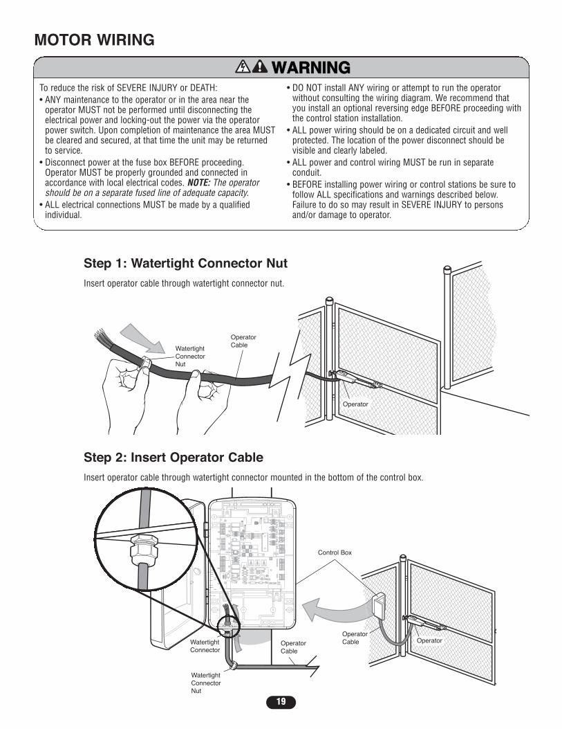
To reduce the risk of SEVERE INJURY or DEATH:• ANY maintenance to the operator or in the area near the
operator MUST not be performed until disconnecting theelectrical power and locking-out the power via the operatorpower switch. Upon completion of maintenance the area MUSTbe cleared and secured, at that time the unit may be returnedto service.
• Disconnect power at the fuse box BEFORE proceeding.Operator MUST be properly grounded and connected inaccordance with local electrical codes. NOTE: The operatorshould be on a separate fused line of adequate capacity.
• ALL electrical connections MUST be made by a qualifiedindividual.
• DO NOT install ANY wiring or attempt to run the operatorwithout consulting the wiring diagram. We recommend thatyou install an optional reversing edge BEFORE proceeding withthe control station installation.
• ALL power wiring should be on a dedicated circuit and wellprotected. The location of the power disconnect should bevisible and clearly labeled.
• ALL power and control wiring MUST be run in separateconduit.
• BEFORE installing power wiring or control stations be sure tofollow ALL specifications and warnings described below.Failure to do so may result in SEVERE INJURY to personsand/or damage to operator.
ATTENTION
AVERTISSEMENT AVERTISSEMENT
AVERTISSEMENT
WARNING
CAUTION
WARNING
WARNINGWARNING
PRECAUCIÓN ADVERTENCIA
ADVERTENCIAADVERTENCIA
MOTOR WIRING
Z22
R91
CLOSEEDGE
R94
R92
R93
L1
R1
R2
Z1
K5
K6
K2
F3
10A 32V
D1Ø
OPEN EDGE/PHOTO
OPENPHOTO
CLOSEPHOTO
R227
R2Ø7
Z2Ø
R223
P1
Z9
Z8
F2
F6
D4
D2
R9
C64JMPR1
R224
U4
CONTROLINPUTS
FORCETIMER TO
CLOSE
OFF MAX
OPEN
SINGLE BUTTON
RESET
STOP
SHADOW
INTERRUPT
CHGROVLD
COM
COM
COM
FUSEOPEN
LOOPINPUTS
POWER
BATT 1BATT 2
F1 20A 32V
R35
D9
Z3
Z4
U3
D1
D27
F5
C11
C13
C12
D15C2R4
R1Ø1
R1ØØ
R9Ø
Q9K1
R196
Q22
D8K3
K4
D21
D22 C4
ACCESSORYOVLD
D6
JMPR2
MOV1MOV2
DB1U2
Z12
24 VAC/SOLARINPUT
GATE 2
ACCESSORYPOWER
MAGLOCK
ALARM
GATE 1
C
C
NC
NO
NO
GRN
WHT
YEL
BLU
RED
BRN
GRN
WHT
YEL
BLU
RED
BRNF4
10A 32V
F7
24V
COMOVLD
TIMERRUNNING
GATE 2
SETOPENLIMIT
SETCLOSELIMIT
LEARNLIMITS
DIAGNOSTIC
GATE 1
J4
LEARNXMITTER
MAGLOCKON OFF
L1L1
Ø14GP14GPØ8989ØEØ14LG14LGØ8989ØEØ14SK14SKØ8989ØE
P2P2
J1J1
J19J19
S1S1
SAVEMAGLOCKMODEEDGEPHOTO
OFFOFF
SINGLENONO
ONONDUALNCNC
LEARNLEARNXMITTERXMITTER
S8S8 1 2 3 4 51 2 3 4 5
ON
2
1
24V
Step 2: Insert Operator CableInsert operator cable through watertight connector mounted in the bottom of the control box.
L1
Ø14GPØ89ØEØ14LGØ89ØEØ14SKØ89ØE
P2
J1
J19
S1
LEARNXMITTER
S8 1 2 3 4 5ON
2
1
Step 1: Watertight Connector NutInsert operator cable through watertight connector nut.
L1
Ø14GPØ89ØEØ14LGØ89ØEØ14SKØ89ØE
P2
J1
J19
S1
LEARNXMITTER
S8 1 2 3 4 5ON
2
1
WatertightConnectorNut
OperatorCable
Operator
Control Box
OperatorOperatorCableOperator
Cable
WatertightConnectorNut
WatertightConnector

20
Step 3: Connect Operator to Control BoardExtend cable and wires to “Gate 1” connector for single gate arm installation and connect as shown. Repeatfor “Gate 2” connector and connect as shown.
Z22
R91
CLOSEEDGE
R94
R92
R93
R1
R2
Z1
K5
K6
K2
F3
10A 32V
D1Ø
OPEN EDGE/PHOTO
OPENPHOTO
CLOSEPHOTO
R227
R2Ø7
Z2Ø
R223
P1
Z9
Z8
F2
F6
D4
D2
R9
C64JMPR1
R224
U4
CONTROLINPUTS
OPEN
SINGLE BUTTON
RESET
STOP
SHADOW
INTERRUPT
CHGROVLD
COM
COM
COM
FUSEOPEN
LOOPINPUTS
POWER
BATT 1BATT 2
F1 20A 32V
R35
D9
Z3
Z4
U3
D1
D27
F5
C11
C13
C12
D15C2R4
R1Ø1
R1ØØ
R9Ø
Q9K1
R196
Q22
D8K3
K4
D21
D22 C4
ACCESSORYOVLD
D6
JMPR2
MOV1MOV2
DB1U2
Z12
24 VAC/SOLARINPUT
GATE 2
ACCESSORYPOWER
MAGLOCK
ALARM
GATE 1
C
C
NC
NO
NO
GRN
WHT
YEL
BLU
RED
BRN
GRN
WHT
YEL
BLU
RED
BRNF4
10A 32V
F7
24V
COMOVLD
TIMERRUNNING
GATE 2
SETOPENLIMIT
SETCLOSELIMIT
LEARNLIMITS
DIAGNOSTIC
GATE 1
J4
R1Z1
K2K2
F3F3
10A 32V
D1Ø
R9Ø
QK1Z12
ACCESSORYPOWER
GATE 1
C
NC
GRN
WHT
YEL
BLU
RED
BRN
GRN
BRN
24V
Brown
Green
White
Yellow
Blue
Red
L1L1
Ø14GP14GPØ8989ØEØ14LG14LGØ8989ØEØ14SK14SKØ8989ØE
P2P2
J1J1
J19J19
S1S1
SAVEMAGLOCKMODEEDGEPHOTO
OFFOFF
SINGLENONO
ONONDUALNCNC
LEARNLEARNXMITTERXMITTER
S8S8 1 2 3 4 51 2 3 4 5
ON
2
1
SWITCHEDACCESSORY
POWER
24V
OVLD
Z1
K2
F3
GATE 2
NC
GRN
WHT
YEL
BLU
RED
BRNBrown
Green
White
Yellow
Blue
Red
ACCESSORYPOWER
24V
D15C2R4 R196
10A 32V
NOTE: Wire connectors can beremoved to simplify wiring.
L1
Ø14GPØ89ØEØ14LGØ89ØEØ14SKØ89ØE
P2
J1
J19
S1
LEARNXMITTER
S8 1 2 3 4 5ON
2
1
AUTO
CAL
LEX
IT 2
CO
M
EXIT
1
HOUSE TELCO
NOTE: Never allow operator cable to drag on ground.
Gate 2
Gate 1
Control Box
OperatorCable “Gate 2”
OperatorCable “Gate 1” Watertight
ConnectorNut
Control Box
OperatorCable
Operator
OffOff
Off
Off
OnOn
OnOnOnOn
Off
OffOff
OffOffOff OnOn Of
fOff
Off
Off LA400
MainRoom
Eug. Dept.Manu. 1 Rm
Main Dept.Manu. 2 Rm
Air (1)Conditioner
Air (2)Conditioner
ConferenceRoom 1
ConferenceRm 2, 3
Refer.Bus 1, 2, 3
ConferenceRoom 2
Comp.Serve 2
Comp.Serve 1
Bathroon.
Z22
R91
CLOSEEDGE
R94
R92
R93
R1
R2
Z1
K5
K6
K2
F3
10A 32V
D1Ø
OPEN EDGE/PHOTO
OPENPHOTO
CLOSEPHOTO
R227
R2Ø7
Z2Ø
R223
P1
Z9
Z8
F2
F6
D4
D2
R9
C64JMPR1
R224
U4
CONTROLINPUTS
CHGROVLD
FUSEOPEN
R35
D9
Z3
Z4
U3
D1
D27
F5
C11
C13
C12
D15C2R4
R1Ø1
R1ØØ
R9Ø
Q9K1
R196
Q22
D8K3
K4
D21
D22 C4
ACCESSORYOVLD
D6
JMPR2
MOV1MOV2
DB1U2
Z12
24 VAC/SOLARINPUT
GATE 2
ACCESSORYPOWER
MAGLOCK
ALARM
GATE 1
C
C
NC
NO
NO
GRN
WHT
YEL
BLU
RED
BRN
GRN
WHT
YEL
BLU
RED
BRNF4
10A 32V
F7
24V
TIMERRUNNING
GATE 2
SETOPENLIMIT
SETCLOSELIMIT
LEARNLIMITS
DIAGNOSTIC
GATE 1
J4
L1L1
Ø14GP14GPØ8989ØEØ14LG14LGØ8989ØEØ14SK14SKØ8989ØE
P2P2
J1J1
J19J19
S1S1
SAVEMAGLOCKMODEEDGEPHOTO
OFFOFF
SINGLENONO
ONONDUALNCNC
LEARNLEARNXMITTERXMITTER
S8S8 1 2 3 4 51 2 3 4 5
ON
2
1
SWITCHEDACCESSORY
POWER
24V
21
Off
Off
On
OnOn
OffOff
Off On Off
Off
L1
Ø14GPØ89ØEØ14LGØ89ØEØ14SKØ89ØE
P2
J1
J19
S1
LEARNXMITTER
S8 1 2 3 4 5ON
2
1
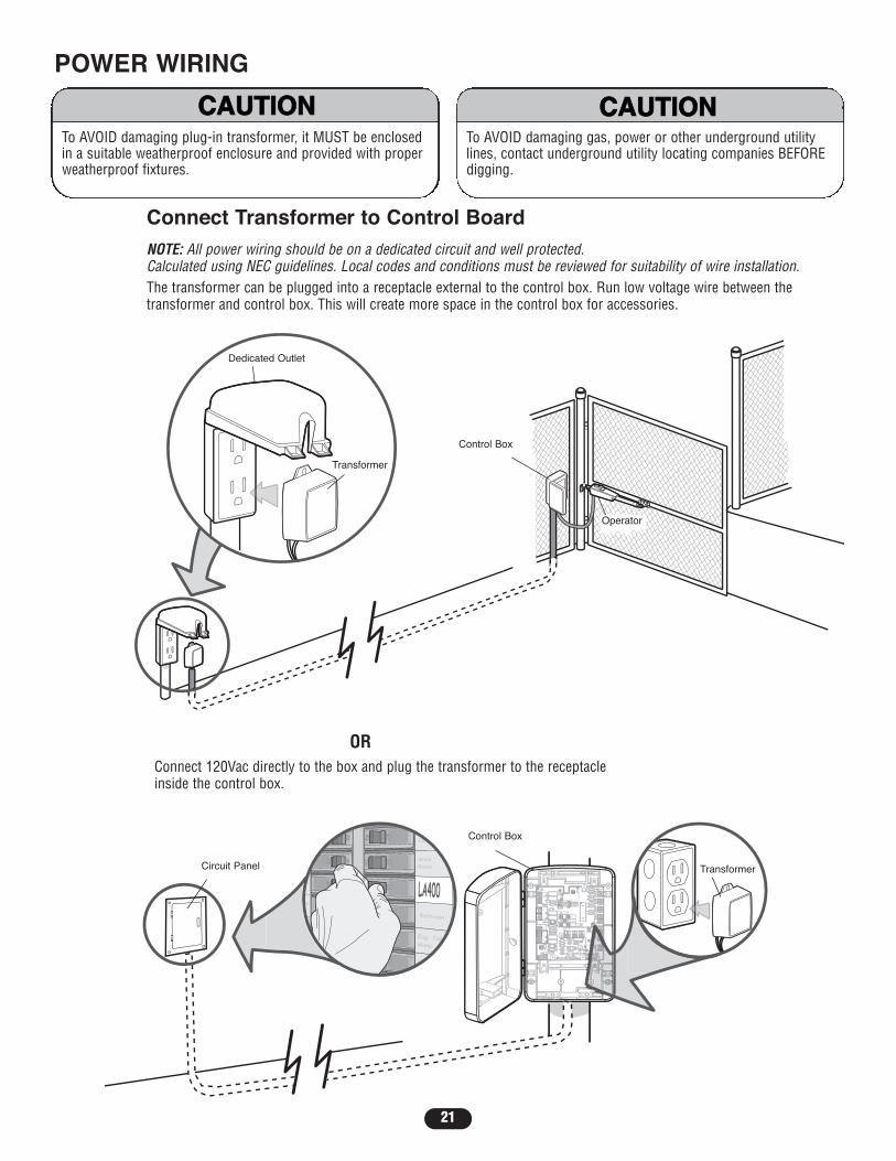
Connect Transformer to Control BoardNOTE: All power wiring should be on a dedicated circuit and well protected.Calculated using NEC guidelines. Local codes and conditions must be reviewed for suitability of wire installation.The transformer can be plugged into a receptacle external to the control box. Run low voltage wire between thetransformer and control box. This will create more space in the control box for accessories.
POWER WIRING
ORConnect 120Vac directly to the box and plug the transformer to the receptacleinside the control box.
To AVOID damaging gas, power or other underground utilitylines, contact underground utility locating companies BEFOREdigging.
ATTENTION
AVERTISSEMENT AVERTISSEMENT
AVERTISSEMENT
WARNING
CAUTIONCAUTION
WARNING
WARNING
PRECAUCIÓN ADVERTENCIA
ADVERTENCIAADVERTENCIA
To AVOID damaging plug-in transformer, it MUST be enclosedin a suitable weatherproof enclosure and provided with properweatherproof fixtures.
ATTENTION
AVERTISSEMENT AVERTISSEMENT
AVERTISSEMENT
WARNING
CAUTIONCAUTION
WARNING
WARNING
PRECAUCIÓN ADVERTENCIA
ADVERTENCIAADVERTENCIA
Control Box
Operator
Dedicated Outlet
Transformer
Control Box
TransformerCircuit Panel

22
EARTH GROUND RODINSTALLATION (OPTIONAL)NOTE: For proper operation, do not connect theearth ground rod to the green screw on the outletplate.1. Install earth ground rod within 3' (0.9 m) of the
operator. 2. Disconnect and remove the green/yellow ground wire connected to the screw terminal of the control board.3. Attach earth ground rod wire to the screw terminal of the control board marked . Ensure the power wiring ground
connection remains securely connected to the green screw on the outlet plate.
FUSEOPEN
Z1
FUSEOPEN
Z3D27
R4
GATE 2
ACCESSORYPOWER
MAGLOCK
ALARM
GATE 1
J4
Z22
R91
CLOSEEDGE
R92
L1
R1
R2
Z1K5
K2
F3
10A 32V
D1Ø
OPEN EDGE/PHOTO
OPENPHOTO
POWER
R227
R2Ø7
Z2Ø
R223
P1
Z9
F2
F6
D4
D2
R9
C64JMPR1
R224
U4
J19
SINGLEBUTTON
CONTROLINPUTS
FORCETIMER TO
CLOSE
OFF MAX
OPEN
SINGLE BUTTON
RESET
STOP
SHADOW
INTERRUPT
CHGROVLD
COM
COM
COM
FUSEOPEN
LOOPINPUTS
POWER
BATT 1BATT 2
F1 20A 32V
R35
D9
Z3
Z4
U3
D1
D27
F5
C11
C13
C12
D15C2
R1Ø1
R1ØØ
R9Ø
Q9K1
R196
Q22
D8K3
K4
D21
D22 C4
ACCESSORYOVLD
D6
JMPR2
MOV1MOV2
DB1U2
Z12
24 VAC/SOLARINPUT
ACCESSORYPOWER
C
C
NC
NO
GATE 1
GATE 2
NO
GRN
WHT
YEL
BLU
RED
BLU
GRN
BRN
GRN
WHT
YEL
BLU
RED
BRN
F4
10A 32V
F7
24V
TIMERRUNNING
GATE 2
SETOPENLIMIT
SETCLOSELIMIT
LEARNLIMITS
DIAGNOSTIC
GATE 1
LEARNXMITTER
2
L1
Ø14GPØ89ØEØ14LGØ89ØEØ14SKØ89ØE
P2
J1
J19
S1
SAVEMAGLOCKMODEEDGEPHOTO
OFFOFF
SINGLENONO
ONONDUALNCNC
LEARNXMITTER
S8 1 2 3 4 5ON
2
1
CONTROLINPUTS
OPEN
SINGLE BUTTON
RESET
STOP
COM
COMPOWER
24V
C2R4
24 VAC/SOLARINPUT
J4
Ground Screw
Control Box
12 Gauge Wire
Earth GroundInstallation (Optional)
3' (0.9 m)
8' (2.4 m)
To AVOID damaging gas, power or other underground utilitylines, contact underground utility locating companies BEFOREdigging.
ATTENTION
AVERTISSEMENT AVERTISSEMENT
AVERTISSEMENT
WARNING
CAUTIONCAUTION
WARNING
WARNING
PRECAUCIÓN ADVERTENCIA
ADVERTENCIAADVERTENCIA

23
MOV2
24 VAC/SOLARINPUT
J4
Z22
R91
CLOSEEDGE
R92
L1
R1
R2
Z1K5
K2
F3
10A 32V
D1Ø
OPEN EDGE/PHOTO
OPENPHOTO
POWER
R227
R2Ø7
Z2Ø
R223
P1
Z9
F2
F6
D4
D2
R9
C64JMPR1
R224
U4
J19
SINGLEBUTTON
CONTROLINPUTS
FORCETIMER TO
CLOSE
OFF MAX
OPEN
SINGLE BUTTON
RESET
STOP
SHADOW
INTERRUPT
CHGROVLD
COM
COM
COM
FUSEOPEN
LOOPINPUTS
POWER
BATT 1BATT 2
F1 20A 32V
R35
D9
Z3
Z4
U3
D1
D27
F5
C11
C13
C12
D15C2
R1Ø1
R1ØØ
R9Ø
Q9K1
R196
Q22
D8K3
K4
D21
D22 C4
ACCESSORYOVLD
D6
JMPR2
MOV1MOV2
DB1U2
Z12
24 VAC/SOLARINPUT
ACCESSORYPOWER
C
C
NC
NO
GATE 1
GATE 2
NO
GRN
WHT
YEL
BLU
RED
BLU
GRN
BRN
GRN
WHT
YEL
BLU
RED
BRN
F4
10A 32V
F7
24V
TIMERRUNNING
GATE 2
SETOPENLIMIT
SETCLOSELIMIT
LEARNLIMITS
DIAGNOSTIC
GATE 1
LEARNXMITTER
2
L1
Ø14GPØ89ØEØ14LGØ89ØEØ14SKØ89ØE
P2
J1
J19
S1
SAVEMAGLOCKMODEEDGEPHOTO
OFFOFF
SINGLENONO
ONONDUALNCNC
LEARNXMITTER
S8 1 2 3 4 5ON
2
1
CONTROLINPUTS
OPEN
SINGLE BUTTON
RESET
STOP
COM
COMPOWER
24V
BATT 1
BATT1 Connector
BATT2 Connector
CONTROL WIRINGTo reduce the risk of FIRE or INJURY to persons use ONLYLiftMaster part #K74-30762 for replacement batteries.
ATTENTION
AVERTISSEMENT AVERTISSEMENT
AVERTISSEMENT
WARNING
CAUTIONCAUTION
WARNING
WARNING
PRECAUCIÓN ADVERTENCIA
ADVERTENCIAADVERTENCIACHARGINGThe 24Vac input can accept a charging transformer (26Vac, 29VAor 36Vdc, 40VA).
SOLAR PANEL KITOptional Liftmaster solar panel(s) kit may be used to charge thebatteries. (See Accessories)
OR
USE DEDICATED CIRCUIT
BATTERYThe main source of power for the operator is thebatteries. The batteries can be charged in circuit byusing a charging transformer or solar panels.

24
OFFOFF
SINGLENONO
ONONDUALNCNC
1 2 3 4 5ON
1 2 3 4 5ON
OFFOFF
SINGLENONO
ONONDUALNCNC
CLOSEEDGE
OPENPHOTO
GATE1
LEARNLIMITS
SETCLOSELIMIT
SETOPENLIMIT
GATE 2
OPEN/EGEPHOTO
CLOSEPHOTO
L1L1
Ø14GPØ89ØEØ14LGØ89ØEØ14SKØ89ØE
P2P2
J1J1
J19J19
S1
SAVEMAGLOCKMODEEDGEPHOTO
OFFOFF
SINGLENONO
ONONDUALNCNC
LEARNXMITTER
S8S8 1 2 3 4 5ON
2
1
S1
SAVEMAGLOCKMODEEDGEPHOTO
OFFOFF
SINGLENONO
ONONDUALNCNC
1 2 3 4 5ON
SWITCHEDACCESSORY
POWER
24V
OVLD
GATE 1 GATE 1 AND GATE 2
FACTORY DEFAULT SHOWN
ADJUSTING / RUNNING THE OPERATORStep 1: Set Dip Switch1. The Save switch must be set to the OFF position prior to programming or changing the switches. 2. Set switch to Single for single gate installation. For Dual (Gate 1 and 2) installation set switch on Dual.NOTE: Save switch must be in the OFF position prior to programming or changing switches for the change to be saved.
25
CLOSEEDGE
OPENPHOTO
GATE1
LEARNLIMITS
SETCLOSELIMIT
SETOPENLIMIT
GATE 2
OPEN/EGEPHOTO
CLOSEPHOTO
FORCE
GATE 2
SETOPENLIMIT
SETCLOSELIMIT
LEARNLIMITS
DIAGNOSTIC
GATE 1
L1L1
Ø14GP14GPØ8989ØEØ14LG14LGØ8989ØEØ14SK14SKØ8989ØE
P2P2
J1J1
J19J19
S1S1
SAVEMAGLOCKMODEEDGEPHOTO
OFFOFF
SINGLENONO
ONONDUALNCNC
LEARNLEARNXMITTERXMITTER
S8S8 1 2 3 4 51 2 3 4 5
ON
2
1
SWITCHEDACCESSORY
POWER
24V
OVLD
FORCE
GATE 2
SETOPENLIMIT
SETCLOSELIMIT
LEARNLIMITS
DIAGNOSTIC
GATE 1
NT
ENT
FORCE
GATE 2
SETOPENLIMIT
SETCLOSELIMIT
LEARNLIMITS
DIAGNOSTIC
GATE 1
FORCE
GATE 2
SETOPENLIMIT
SETCLOSELIMIT
LEARNLIMITS
DIAGNOSTIC
GATE 1
CS
CLOL
FORCE
GATE 2
SETOPENLIMIT
SETCLOSELIMIT
LEARNLIMITS
DIAGNOSTIC
GATE 1
FORCE
GATE 2
SETOPENLIMIT
SETCLOSELIMIT
LEARNLIMITS
DIAGNOSTIC
GATE 1
FORCE
GATE 2
SETOPENLIMIT
SETCLOSELIMIT
LEARNLIMITS
DIAGNOSTIC
GATE 1
S1
SAVEMAGLOCKMODEEDGEPHOTO
OFFOFF
SINGLENONO
ONONDUALNCNC
1 2 3 4 5ON
SINGLEBUTTON
O
SINGLE B
SINGLEBUTTON
FORCE
GATE 2
SETOPENLIMIT
SETCLOSELIMIT
LEARNLIMITS
DIAGNOSTIC
GATE 1
CS
CLL
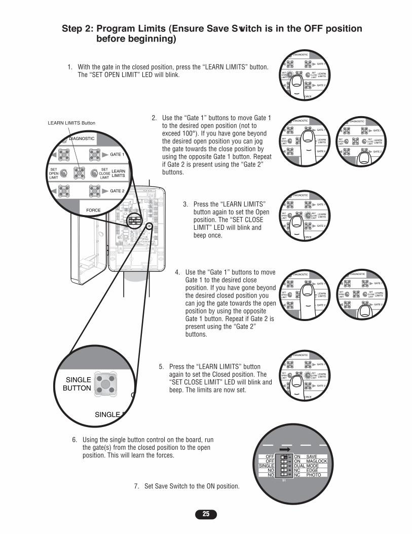
Step 2: Program Limits (Ensure Save Switch is in the OFF positionbefore beginning)
1. With the gate in the closed position, press the “LEARN LIMITS” button.The “SET OPEN LIMIT” LED will blink.
2. Use the “Gate 1” buttons to move Gate 1to the desired open position (not toexceed 100°). If you have gone beyondthe desired open position you can jogthe gate towards the close position byusing the opposite Gate 1 button. Repeatif Gate 2 is present using the “Gate 2”buttons.
3. Press the “LEARN LIMITS”button again to set the Openposition. The “SET CLOSELIMIT” LED will blink andbeep once.
4. Use the “Gate 1” buttons to moveGate 1 to the desired closeposition. If you have gone beyondthe desired closed position youcan jog the gate towards the openposition by using the oppositeGate 1 button. Repeat if Gate 2 ispresent using the “Gate 2”buttons.
5. Press the “LEARN LIMITS” buttonagain to set the Closed position. The“SET CLOSE LIMIT” LED will blink andbeep. The limits are now set.
6. Using the single button control on the board, runthe gate(s) from the closed position to the openposition. This will learn the forces.
7. Set Save Switch to the ON position.
LEARN LIMITS Button
26
CLOSEEDGE
OPENPHOTO
SETSETOPENOPENLIMITLIMIT
FORCETIMER TO
CLOSE
OPEN/EGEPHOTO
CLOSEPHOTO
Z9
Z8
FORCETIMER TO
CLOSE
OFF MAXMIN MAX
BI-PARTDELAY
OFF MAX
L1L1
Ø14GP14GPØ8989ØEØ14LG14LGØ8989ØEØ14SK14SKØ8989ØE
P2P2
J1J1
J19J19
S1S1
SAVEMAGLOCKMODEEDGEPHOTO
OFFOFF
SINGLENONO
ONONDUALNCNC
LEARNLEARNXMITTERXMITTER
S8S8 1 2 3 4 51 2 3 4 5
ON
2
1
BIPARTDELAY
SWITCHEDACCESSORY
POWER
24V
OVLD
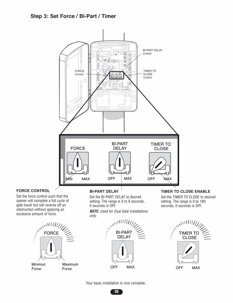
TIMER TO CLOSE ENABLESet the TIMER TO CLOSE to desiredsetting. The range is 0 to 180seconds, 0 seconds is OFF.
FORCE CONTROLSet the force control such that theopener will complete a full cycle ofgate travel but will reverse off anobstruction without applying anexcessive amount of force.
Step 3: Set Force / Bi-Part / Timer
SETOPENLIMIT
MinimunForce
MaximumForce
FORCE
L1
Ø14GPØ89ØEØ14LGØ89ØEØ14SKØ89ØE
P2
J1
J19
S1
LEARNXMITTER
S8 1 2 3 4 5ON
2
1
SETOPENLIMIT
TIMER TO CLOSE
OFF MAX
L1
Ø14GPØ89ØEØ14LGØ89ØEØ14SKØ89ØE
P2
J1
J19
S1
LEARNXMITTER
S8 1 2 3 4 5ON
2
1
SETOPENLIMIT
L1
Ø14GPØ89ØEØ14LGØ89ØEØ14SKØ89ØE
P2
J1
J19
S1
LEARNXMITTER
S8 1 2 3 4 5ON
2
1
BI-PARTDELAY
OFF MAX
BI-PART DELAYSet the BI-PART DELAY to desiredsetting. The range is 0 to 8 seconds, 0 seconds is OFF.NOTE: Used for Dual Gate installationsonly.
Your basic installation is now complete.
FORCEControl
TIMER TOCLOSEControl
BI-PART DELAYControl

27
To Add or Reprogram a Remote Control1. Press and release “LEARN XMITTER” button (LED will light up).2. Press and hold remote button, the LED will flash, alarm will beep twice and the LED will go out.3. Repeat steps 1 and 2 until all remote controls are programmed (50 remote controls maximum).NOTE: For highest level of security, we recommend the 315 MHz, Security✚® line of products. Refer to Accessories.
NOTICE: To comply with FCC and or Industry Canada (IC) rules, adjustment or modifications of thisreceiver and/or transmitter are prohibited, except for changing the code setting or replacing thebattery. THERE ARE NO OTHER USER SERVICEABLE PARTS.Tested to Comply with FCC Standards FOR HOME OR OFFICE USE. Operation is subject to thefollowing two conditions: (1) this device may not cause harmful interference, and (2) this devicemust accept any interference received, including interference that may cause undesired operation.
CLOSEEDGE
OPENPHOTO
OPEN/EGEPHOTO
CLOSEPHOTO
R1
LEARNXMITTER
L1L1
Ø14GP14GPØ8989ØEØ14LG14LGØ8989ØEØ14SK14SKØ8989ØE
P2P2
J1J1
J19J19
S1S1
SAVEMAGLOCKMODEEDGEPHOTO
OFFOFF
SINGLENONO
ONONDUALNCNC
LEARNXMITTER
S8 1 2 3 4 51 2 3 4 5
ON
2
1
SWITCHEDACCESSORY
POWER
24V
OVLD
L1
Ø14GPØ89ØEØ14LGØ89ØEØ14SKØ89ØE
P2
J1
J19
S1
1 2 3 4 5ON
To Erase All CodesTo deactivate any unwanted remote controls, firsterase all codes:Press and hold the “LEARN XMITTER” button onlogic board until the learn indicator light goes out(approximately 6 seconds). All previous codes arenow erased. Reprogram each remote control orkeyless entry you wish to use.
OPTIONAL CONTROL AND SAFETY DEVICES
Remote Control“LEARN XMITTER” Button
OFFOFF
SINGLEEDGE NO
ONONDUALNC
OFFOFF
SINGLE
EYE NO
ONONDUAL
NC
ONMAG DELAYOFF
OFFMAG DELAY
ON
ONONDUALNCNC
OFFOFF
SINGLENONO
1 2 3 4 5ON
1 2 3 4 5ON
1 2 3 4 5ON
1 2 3 4 5ON
1 2 3 4 5ON
1 2 3 4 5ON
SAVEOFF
1 2 3 4 5ON
1 2 3 4 5ON
SAVEON
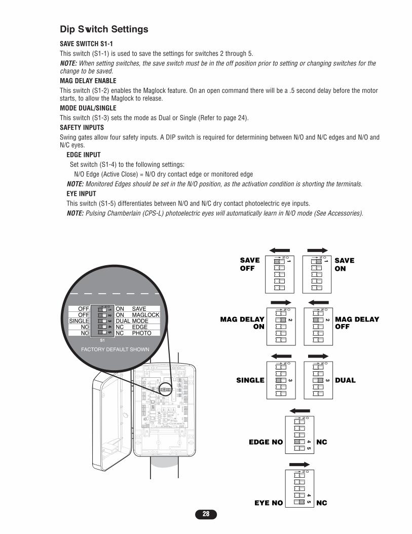
Dip Switch SettingsSAVE SWITCH S1-1This switch (S1-1) is used to save the settings for switches 2 through 5.NOTE: When setting switches, the save switch must be in the off position prior to setting or changing switches for thechange to be saved.MAG DELAY ENABLEThis switch (S1-2) enables the Maglock feature. On an open command there will be a .5 second delay before the motorstarts, to allow the Maglock to release.MODE DUAL/SINGLEThis switch (S1-3) sets the mode as Dual or Single (Refer to page 24). SAFETY INPUTSSwing gates allow four safety inputs. A DIP switch is required for determining between N/O and N/C edges and N/O andN/C eyes.
EDGE INPUTSet switch (S1-4) to the following settings:
N/O Edge (Active Close) = N/O dry contact edge or monitored edgeNOTE: Monitored Edges should be set in the N/O position, as the activation condition is shorting the terminals.EYE INPUTThis switch (S1-5) differentiates between N/O and N/C dry contact photoelectric eye inputs. NOTE: Pulsing Chamberlain (CPS-L) photoelectric eyes will automatically learn in N/O mode (See Accessories).
CLOSEEDGE
OPENPHOTO
GATE1
LEARNLIMITS
SETCLOSELIMIT
SETOPENLIMIT
GATE 2
OPEN/EGEPHOTO
CLOSEPHOTO
L1L1
Ø14GPØ89ØEØ14LGØ89ØEØ14SKØ89ØE
P2P2
J1J1
J19J19
S1
SAVEMAGLOCKMODEEDGEPHOTO
OFFOFF
SINGLENONO
ONONDUALNCNC
LEARNXMITTER
S8S8 1 2 3 4 5ON
2
1
S1
SAVEMAGLOCKMODEEDGEPHOTO
OFFOFF
SINGLENONO
ONONDUALNCNC
1 2 3 4 5ON
SWITCHEDACCESSORY
POWER
24V
OVLD
FACTORY DEFAULT SHOWN
28

29
Z22
R91
CLOSEEDGE
R92
L1
R1
R2
Z1K5
K2
F3
10A 32V
D1Ø
OPEN EDGE/PHOTO
OPENPHOTO
POWER
R227
R2Ø7
Z2Ø
R223
P1
Z9
F2
F6
D4
D2
R9
C64JMPR1
R224
U4
J19
SINGLEBUTTON
CONTROLINPUTS
FORCETIMER TO
CLOSE
OFF MAX
OPEN
SINGLE BUTTON
RESET
STOP
SHADOW
INTERRUPT
CHGROVLD
COM
COM
COM
FUSEOPEN
LOOPINPUTS
POWER
BATT 1BATT 2
F1 20A 32V
R35
D9
Z3
Z4
U3
D1
D27
F5
C11
C13
C12
D15C2
R1Ø1
R1ØØ
R9Ø
Q9K1
R196
Q22
D8K3
K4
D21
D22 C4
ACCESSORYOVLD
D6
JMPR2
MOV1MOV2
DB1U2
Z12
24 VAC/SOLARINPUT
ACCESSORYPOWER
C
C
NC
NO
GATE 1
GATE 2
NO
GRN
WHT
YEL
BLU
RED
BLU
GRN
BRN
GRN
WHT
YEL
BLU
RED
BRN
F4
10A 32V
F7
24V
TIMERRUNNING
GATE 2
SETOPENLIMIT
SETCLOSELIMIT
LEARNLIMITS
DIAGNOSTIC
GATE 1
LEARNXMITTER
2
L1
Ø14GPØ89ØEØ14LGØ89ØEØ14SKØ89ØE
P2
J1
J19
S1
SAVEMAGLOCKMODEEDGEPHOTO
OFFOFF
SINGLENONO
ONONDUALNCNC
LEARNXMITTER
S8 1 2 3 4 5ON
2
1
CONTROLINPUTS
OPEN
SINGLE BUTTON
RESET
STOP
COM
COMPOWER
COM
COM
CONTROLINPUTS
OPEN
SINGLE BUTTON
RESET
STOP
POWER
SWITCHEDACCESSORY
POWER
24V
OVLD
Wire Stop Button (Optional)A jumper wire is factory installed between the stop and common input.Stop (N/C) - Stop only (does not reset alarm).NOTE: Stop jumper is required for normal operation (the Stop LED will be lit except when the control board goes intoSleep Mode). Remove only if remotely mounted Stop button is added.

30
Z22
R91
CLOSEEDGE
R92
L1
R1
R2
Z1K5
K2
F3
10A 32V
D1Ø
OPEN EDGE/PHOTO
OPENPHOTO
POWER
R227
R2Ø7
Z2Ø
R223
P1
Z9
F2
F6
D4
D2
R9
C64JMPR1
R224
U4
J19
SINGLEBUTTON
CONTROLINPUTS
FORCETIMER TO
CLOSE
OFF MAX
OPEN
SINGLE BUTTON
RESET
STOP
SHADOW
INTERRUPT
CHGROVLD
COM
COM
COM
FUSEOPEN
LOOPINPUTS
POWER
BATT 1BATT 2
F1 20A 32V
R35
D9
Z3
Z4
U3
D1
D27
F5
C11
C13
C12
D15C2
R1Ø1
R1ØØ
R9Ø
Q9K1
R196
Q22
D8K3
K4
D21
D22 C4
ACCESSORYOVLD
D6
JMPR2
MOV1MOV2
DB1U2
Z12
24 VAC/SOLARINPUT
ACCESSORYPOWER
C
C
NC
NO
GATE 1
GATE 2
NO
GRN
WHT
YEL
BLU
RED
BLU
GRN
BRN
GRN
WHT
YEL
BLU
RED
BRN
F4
10A 32V
F7
24V
TIMERRUNNING
GATE 2
SETOPENLIMIT
SETCLOSELIMIT
LEARNLIMITS
DIAGNOSTIC
GATE 1
LEARNXMITTER
2
L1
Ø14GPØ89ØEØ14LGØ89ØEØ14SKØ89ØE
P2
J1
J19
S1
SAVEMAGLOCKMODEEDGEPHOTO
OFFOFF
SINGLENONO
ONONDUALNCNC
LEARNXMITTER
S8 1 2 3 4 5ON
2
1
CONTROLINPUTS
OPEN
SINGLE BUTTON
RESET
STOP
COM
COMPOWER
COM
COM
CONTROLINPUTS
OPEN
SINGLE BUTTON
RESET
STOP
POWER
24V
OPENOpens only or reverses a closing gate.
SBC (SINGLE BUTTON CONTROL) INPUTThis input will command the gate to OPEN / STOP / CLOSE / STOP in sequence.
RESET CONTROL INPUTThe control box has a factory installed internal reset button. These terminals are intended for use with a single resetbutton that is installed within line of sight of the gate. This input functions to reset the alarms. This input will NOT stopthe gate.NOTE: All Control Inputs must be Normally Open (N.O.) dry contact type.
OPEN
COMMON
SINGLEBUTTON
COMMON
COMMON
RESET
AND/OR
AND/OR
FREQ
PRESENCERELAY 2
SENS
FREQMADE IN USA
EXIT LOOP
OPEN INPUT AND EXIT LOOPThese terminals are intended for use as a general open control. Accessories such astelephone entry systems, radio receivers (open only applications), exit loop detectors,keypads and 7-day timers may be wired to this input.

31
SHADOW
INTERRUPT
CHGROVLD
COM
FUSEOPEN
LOOPINPUTS
BATT 1BATT 2
F1 20A 32V
Z22
R91
CLOSEEDGE
R92
L1
R1
R2
Z1K5
K2
F3
10A 32V
D1Ø
OPEN EDGE/PHOTO
OPENPHOTO
POWER
R227
R2Ø7
Z2Ø
R223
P1
Z9
F2
F6
D4
D2
R9
C64JMPR1
R224
U4
J19
SINGLEBUTTON
CONTROLINPUTS
FORCETIMER TO
CLOSE
OFF MAX
OPEN
SINGLE BUTTON
RESET
STOP
SHADOW
INTERRUPT
CHGROVLD
COM
COM
COM
FUSEOPEN
LOOPINPUTS
POWER
BATT 1BATT 2
F1 20A 32V
R35
D9
Z3
Z4
U3
D1
D27
F5
C11
C13
C12
D15C2
R1Ø1
R1ØØ
R9Ø
Q9K1
R196
Q22
D8K3
K4
D21
D22 C4
ACCESSORYOVLD
D6
JMPR2
MOV1MOV2
DB1U2
Z12
24 VAC/SOLARINPUT
ACCESSORYPOWER
C
C
NC
NO
GATE 1
GATE 2
NO
GRN
WHT
YEL
BLU
RED
BLU
GRN
BRN
GRN
WHT
YEL
BLU
RED
BRN
F4
10A 32V
F7
24V
TIMERRUNNING
GATE 2
SETOPENLIMIT
SETCLOSELIMIT
LEARNLIMITS
DIAGNOSTIC
GATE 1
LEARNXMITTER
2
L1
Ø14GPØ89ØEØ14LGØ89ØEØ14SKØ89ØE
P2
J1
J19
S1
SAVEMAGLOCKMODEEDGEPHOTO
OFFOFF
SINGLENONO
ONONDUALNCNC
LEARNXMITTER
S8 1 2 3 4 5ON
2
1
CONTROLINPUTS
OPEN
SINGLE BUTTON
RESET
STOP
COM
COMPOWER
COM
LOOPINPUTS
FREQ
PRESENCERELAY 2
SENS
FREQMADE IN USA
24V
Loop InputsShadow Loop Input Terminal and CommonThis input protects cars by preventing the gate from moving off of the open or close limit when the shadow loop inputis active.NOTE: Shadow Loop is disabled when gate is moving.Interrupt Loop Input Terminal and CommonThis input functions to reverse a closing gate to the open limit. Latching this input will reset the timer to close.
NOTE: Additional enclosure required. Refer toloop detector manufacturer instructions forconnections.
NORMALLY OPENSHADOW LOOP
NORMALLY OPENINTERRUPT LOOP
COMMON LOOP
32
CLOSEEDGE
OPEN EDGEPHOTO
OPENPHOTO
CLOSEPHOTO
Z22
R91
CLOSEEDGE
R92
L1
R1
R2
Z1K5
K2
F3
10A 32V
D1Ø
OPEN EDGE/PHOTO
OPENPHOTO
POWER
R227
R2Ø7
Z2Ø
R223
P1
Z9
F2
F6
D4
D2
R9
C64JMPR1
R224
U4
J19
SINGLEBUTTON
CONTROLINPUTS
FORCETIMER TO
CLOSE
OFF MAX
OPEN
SINGLE BUTTON
RESET
STOP
SHADOW
INTERRUPT
CHGROVLD
COM
COM
COM
FUSEOPEN
LOOPINPUTS
POWER
BATT 1BATT 2
F1 20A 32V
R35
D9
Z3
Z4
U3
D1
D27
F5
C11
C13
C12
D15C2
R1Ø1
R1ØØ
R9Ø
Q9K1
R196
Q22
D8K3
K4
D21
D22 C4
ACCESSORYOVLD
D6
JMPR2
MOV1MOV2
DB1U2
Z12
24 VAC/SOLARINPUT
ACCESSORYPOWER
C
C
NC
NO
GATE 1
GATE 2
NO
GRN
WHT
YEL
BLU
RED
BLU
GRN
BRN
GRN
WHT
YEL
BLU
RED
BRN
F4
10A 32V
F7
24V
TIMERRUNNING
GATE 2
SETOPENLIMIT
SETCLOSELIMIT
LEARNLIMITS
DIAGNOSTIC
GATE 1
LEARNXMITTER
2
L1
Ø14GPØ89ØEØ14LGØ89ØEØ14SKØ89ØE
P2
J1
J19
S1
SAVEMAGLOCKMODEEDGEPHOTO
OFFOFF
SINGLENONO
ONONDUALNCNC
LEARNXMITTER
S8 1 2 3 4 5ON
2
1
CONTROLINPUTS
OPEN
SINGLE BUTTON
RESET
STOP
COM
COMPOWER
COM
LOOPINPUTS
CLOSEEDGE
OPEN EDGE/PHOTO
OPENPHOTO
CLOSEPHOTO
24V
OVLD
SWITCHEDACCESSORY
POWER
BROWN
BLUE
BROWN
BLUE
BR
OW
N
BLU
E
BR
OW
N
BLU
EB
RO
WN
BR
O
WN
BLUE
BLUE
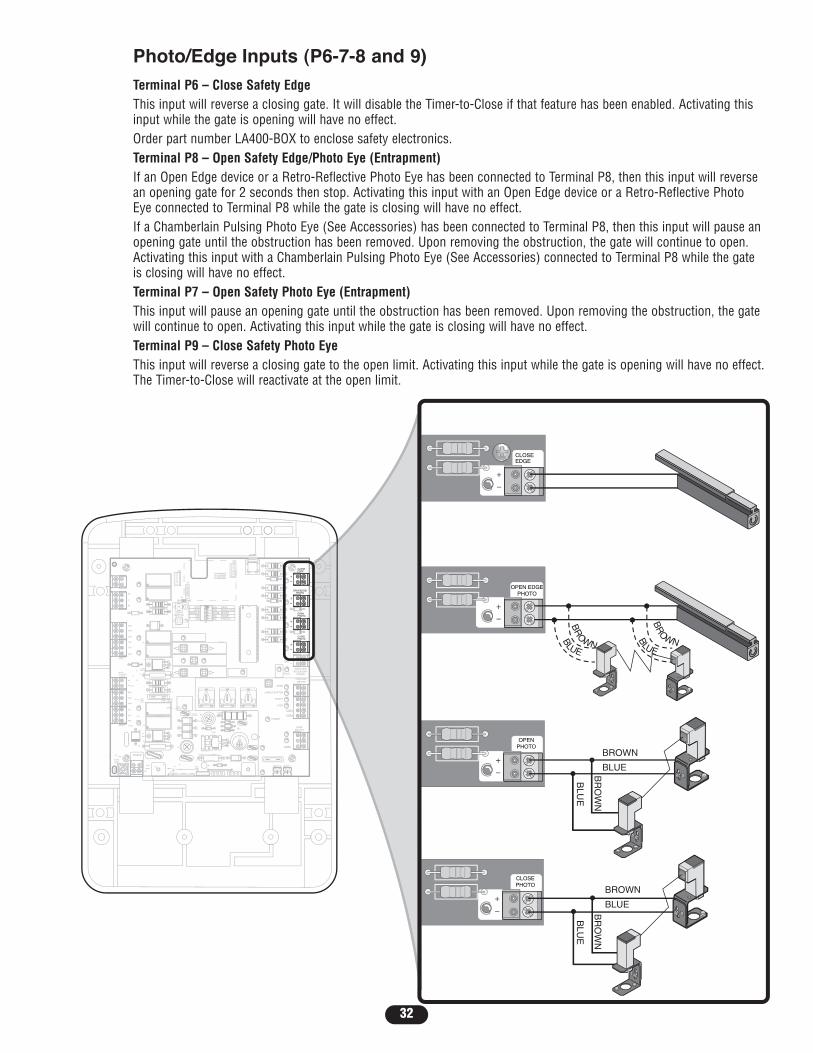
Photo/Edge Inputs (P6-7-8 and 9)Terminal P6 – Close Safety EdgeThis input will reverse a closing gate. It will disable the Timer-to-Close if that feature has been enabled. Activating thisinput while the gate is opening will have no effect.Order part number LA400-BOX to enclose safety electronics.Terminal P8 – Open Safety Edge/Photo Eye (Entrapment)If an Open Edge device or a Retro-Reflective Photo Eye has been connected to Terminal P8, then this input will reversean opening gate for 2 seconds then stop. Activating this input with an Open Edge device or a Retro-Reflective PhotoEye connected to Terminal P8 while the gate is closing will have no effect.If a Chamberlain Pulsing Photo Eye (See Accessories) has been connected to Terminal P8, then this input will pause anopening gate until the obstruction has been removed. Upon removing the obstruction, the gate will continue to open.Activating this input with a Chamberlain Pulsing Photo Eye (See Accessories) connected to Terminal P8 while the gateis closing will have no effect.Terminal P7 – Open Safety Photo Eye (Entrapment)This input will pause an opening gate until the obstruction has been removed. Upon removing the obstruction, the gatewill continue to open. Activating this input while the gate is closing will have no effect.Terminal P9 – Close Safety Photo EyeThis input will reverse a closing gate to the open limit. Activating this input while the gate is opening will have no effect.The Timer-to-Close will reactivate at the open limit.

PHOTO-ELECTRIC CONTROLS
MODEL DESCRIPTION VOLTAGECPS-LN4
CPS-RN4
SENSING EDGES
MODEL DESCRIPTIONG65MG0204
G65MG0205
G65MGR205
G65MGS205
33
Z22
R91
CLOSEEDGE
R94
R92
R93
L1
R1
R2
Z1
K5
Ø14GPØ89ØEØ14LGØ89ØEØ14SKØ89ØE
K6
K2
F3
10A 32V
D1Ø
OPEN EDGE/PHOTO
OPENPHOTO
CLOSEPHOTO
J18
R227
R2Ø7
Z2Ø
R223
P1
Z9
Z8
F2
F6
D4
D2
R9
C64JMPR1
R224
U4
P2
J1
J19
SINGLEBUTTON
CONTROLINPUTS
FORCEBIPARTDELAY
TIMER TOCLOSE
MIN MAX OFF MAX OFF MAX
OPEN
SINGLE BUTTON
RESET
STOP
SHADOW
S1
INTERRUPT
CHGROVLD
COM
COM
COM
FUSEOPEN
LOOPINPUTS
POWER
BATT 1BATT 2
F1 20A 32V
R35
D9
Z3
Z4
U3
D1
D27
F5
C11
C13
C12
D15C2R4
R1Ø1
R1ØØ
R9Ø
Q9K1
R196
Q22
D8K3
K4
D21
D22 C4
ACCESSORYOVLD
D6
JMPR2
MOV1MOV2
DB1U2
Z12
24 VAC/SOLARINPUT
GATE 2
ACCESSORYPOWER
MAGLOCK
ALARM
GATE 1
C
C
NC
NO
NO
GRN
WHT
YEL
BLU
RED
BRN
GRN
WHT
YEL
BLU
RED
BRNF4
10A 32V
F7
24V
24V
COMOVLD
OVLD
SWITCHEDACCESSORY
POWERTIMER
RUNNINGGATE 2
SETOPENLIMIT
SETCLOSELIMIT
LEARNLIMITS
DIAGNOSTIC
GATE 1
J4
SAVEMAGLOCKMODEEDGEPHOTO
OFFOFF
SINGLENONO
ONONDUALNCNC
LEARNXMITTER
S8 1 2 3 4 5ON
2
1
Emitter, receiver and mounting brackets - 30' (9 m) Ranges
Emitter with reflector and mounting brackets
+24Vdc
Miller MG020 2-wire electric edge for gates. Sensitized on three sides. (Requires mounting channel.PIN:G65ME120C5)
Miller MG020 2-wire electric edge for gates. Sensitized on three sides. (Requires mounting channel.PIN:G65ME120C5)
Miller MGR20 2-wire electric edge in 5' (1.5 m) lengths for 2" (5 cm) round post.
Miller MGR20 2-wire electric edge in 5' (1.5 m) lengths for 2" (5 cm) square post.
Safety Accessories for Secondary Entrapment ProtectionThe following devices are acceptable for Safety Accessories for secondary entrapment protection. These devices havebeen tested with the LA400 to meet the requirements of UL325 and UL991.
AccessoryPower
Maglock(optional)
Fault Alarm
Solenoid Lock(optional)
MaglockWhen enabled, the maglock output is activated (energized) while the gateis in motion.
Auxiliary Output Power for Optional Devices(2) +24Vdc Outputs have been provided for optional devices
+24Vdc
* Provides 24VDC. Do not exceed 500MA with 115Vacpower supply or 300MA with 24Vac power supply.
*
*

34
OPERATIONReset ButtonThe reset button is located on the outside of the control box and serves several functions.Obstruction/Entrapment ResetIf gate encounters two consecutive obstructions, the control system will go into an entrapment alarm condition and thecontrol board will require resetting. This is achieved by simply pushing the “Reset Button” located on the outside of thecontrol box.Party Mode (Timer Defeat - Hold Open)When the “Timer to Close” feature is activated for normal daily operation andyou wish to leave the gate(s) in the open postion for any extended period oftime you can activate the “Party Mode” by pushing the “Reset Button” locatedon the outside of the electrical box. To exit this mode, simply give the gate(s)a command to run by using the remote control. This will close the gate(s) andreturn the operator to normal operation.
Remote ControlOnce the remote control has been programmed unit will operate as follows:When gate is in the closed position, activation of the remote control button will open the gate. During the open cycleanother activation of the remote control will stop the gate and the next activation of the remote control will close the gate.When the gate is in the open position, activation of the remote controlbutton will close the gate. During the close cycle another activation of theremote control will stop the gate and the next activation of the remotecontrol will open the gate.
Manual ReleaseThe drive mechanism can be released. The gate can then be operated manually (power failure). With a new drivemechanism, the release action may sometimes feel stiff/jerky. This is normal and has no effect on function.Release1. Insert the key into the lock.2. Turn the key counter-clockwise 180°.3. Turn the release lever counter-clockwise 180°.4. Done! Operator is in manual mode.
Engage1. Turn the release lever clockwise 180°. This engages the motor.2. Turn the key clockwise 180°. This locks the release lever.3. Remove the key and store in a safe place.4. Done! Back in automatic mode.
RESET
RESET
L1
Ø14GPØ89ØEØ14LGØ89ØEØ14SKØ89ØE
P2
J1
J19
S1
1 2 3 4 5ON
Control Box ResetButton
35
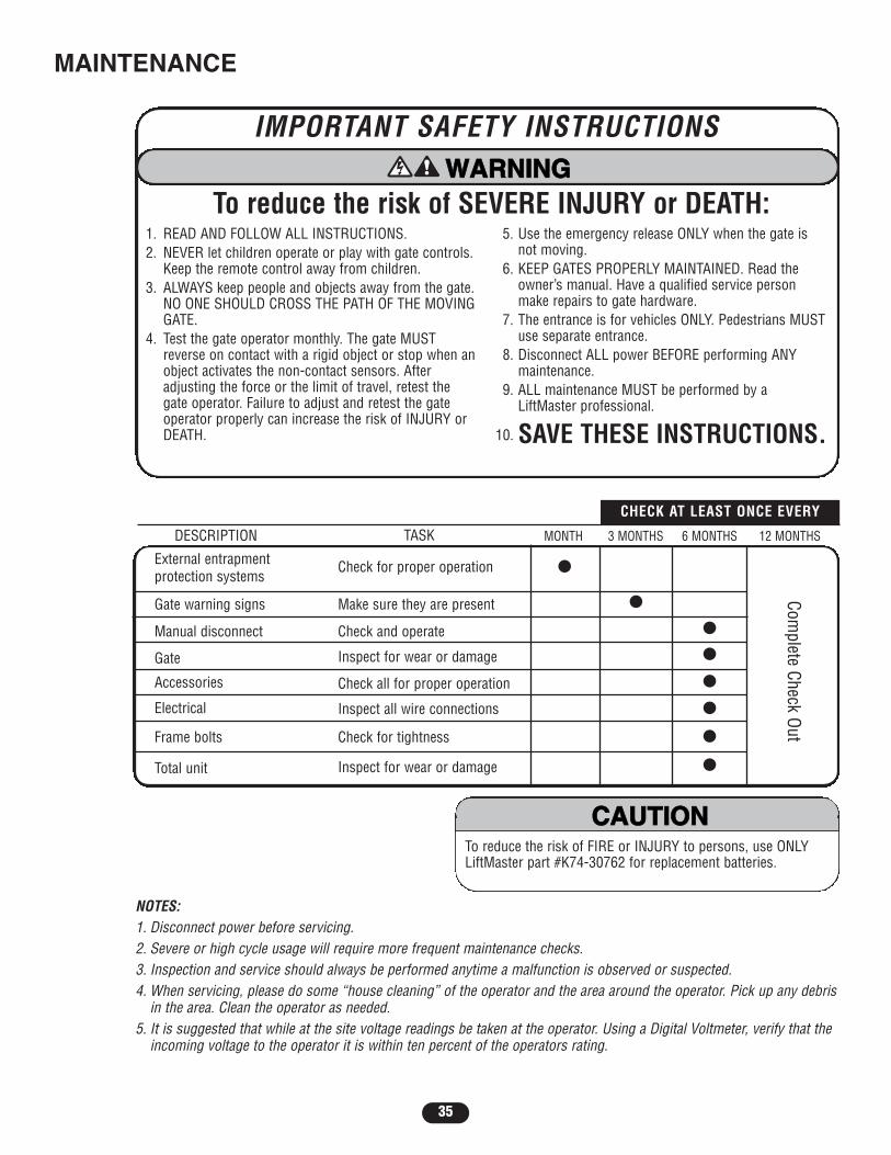
External entrapmentprotection systems
Check for proper operation
Gate warning signs ●Make sure they are present
Manual disconnect ●Check and operate
Gate ●Inspect for wear or damage
Accessories ●Check all for proper operation
Electrical ●Inspect all wire connections
Frame bolts ●Check for tightness
Total unit ●Inspect for wear or damage
6 MONTHS3 MONTHS 12 MONTHSTASK
CHECK AT LEAST ONCE EVERY
Complete Check Out
NOTES:1. Disconnect power before servicing.2. Severe or high cycle usage will require more frequent maintenance checks.3. Inspection and service should always be performed anytime a malfunction is observed or suspected.4. When servicing, please do some “house cleaning” of the operator and the area around the operator. Pick up any debris
in the area. Clean the operator as needed.5. It is suggested that while at the site voltage readings be taken at the operator. Using a Digital Voltmeter, verify that the
incoming voltage to the operator it is within ten percent of the operators rating.
DESCRIPTION
IMPORTANT SAFETY INSTRUCTIONS
To reduce the risk of SEVERE INJURY or DEATH:1. READ AND FOLLOW ALL INSTRUCTIONS.2. NEVER let children operate or play with gate controls.
Keep the remote control away from children.3. ALWAYS keep people and objects away from the gate.
NO ONE SHOULD CROSS THE PATH OF THE MOVINGGATE.
4. Test the gate operator monthly. The gate MUSTreverse on contact with a rigid object or stop when anobject activates the non-contact sensors. Afteradjusting the force or the limit of travel, retest thegate operator. Failure to adjust and retest the gateoperator properly can increase the risk of INJURY orDEATH.
5. Use the emergency release ONLY when the gate isnot moving.
6. KEEP GATES PROPERLY MAINTAINED. Read theowner’s manual. Have a qualified service personmake repairs to gate hardware.
7. The entrance is for vehicles ONLY. Pedestrians MUSTuse separate entrance.
8. Disconnect ALL power BEFORE performing ANYmaintenance.
9. ALL maintenance MUST be performed by aLiftMaster professional.
10. SAVE THESE INSTRUCTIONS.ATTENTION
AVERTISSEMENT AVERTISSEMENT
AVERTISSEMENT
WARNING
CAUTION
WARNING
WARNINGWARNING
PRECAUCIÓN ADVERTENCIA
ADVERTENCIAADVERTENCIA
MONTH
●
To reduce the risk of FIRE or INJURY to persons, use ONLYLiftMaster part #K74-30762 for replacement batteries.
ATTENTION
AVERTISSEMENT AVERTISSEMENT
AVERTISSEMENT
WARNING
CAUTIONCAUTION
WARNING
WARNING
PRECAUCIÓN ADVERTENCIA
ADVERTENCIAADVERTENCIA
MAINTENANCE
36
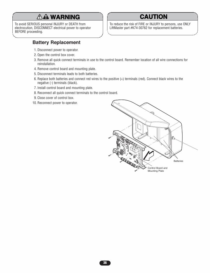
Battery Replacement1. Disconnect power to operator.2. Open the control box cover.3. Remove all quick connect terminals in use to the control board. Remember location of all wire connections for
reinstallation.4. Remove control board and mounting plate.5. Disconnect terminals leads to both batteries.6. Replace both batteries and connect red wires to the positive (+) terminals (red). Connect black wires to the
negative (-) terminals (black).7. Install control board and mounting plate.8. Reconnect all quick connect terminals to the control board.9. Close cover of control box.
10. Reconnect power to operator.
To avoid SERIOUS personal INJURY or DEATH fromelectrocution, DISCONNECT electrical power to operatorBEFORE proceeding.
ATTENTION
AVERTISSEMENT AVERTISSEMENT
AVERTISSEMENT
WARNING
CAUTION
WARNING
WARNINGWARNING
PRECAUCIÓN ADVERTENCIA
ADVERTENCIAADVERTENCIA
To reduce the risk of FIRE or INJURY to persons, use ONLYLiftMaster part #K74-30762 for replacement batteries.
ATTENTION
AVERTISSEMENT AVERTISSEMENT
AVERTISSEMENT
WARNING
CAUTIONCAUTION
WARNING
WARNING
PRECAUCIÓN ADVERTENCIA
ADVERTENCIAADVERTENCIABatteries
Control Board andMounting Plate

37
Z22
R91
CLOSEEDGE
R94
R92
R93
L1
R1
R2
Z1
K5
Ø14GPØ89ØE Ø14LGØ89ØE Ø14SKØ89ØE
K6
K2
F3
10A 32V
D1Ø
OPEN EDGE/PHOTO
OPENPHOTO
CLOSEPHOTO
J18
R227
R2Ø7
Z2 Ø
R223
P1
Z9
Z8
F2
F6
D4
D2
R9
C64 JMPR1
R224
U4
P2
J1
J19
SINGLEBUTTON
CONTROLINPUTS
FORCEBIPARTDELAY
TIMER TOCLOSE
MIN MAX OFF MAX OFF MAX
OPEN
SINGLE BUTTON
RESET
STOP
SHADOW
S1
INTERRUPT
CHGROVLD
COM
COM
COM
FUSEOPEN
LOOPINPUTS
POWER
BATT 1BATT 2
F1 20A 32V
R35
D9
Z3
Z4
U3
D1
D27
F5
C11
C13
C12
D15 C2 R4
R1Ø1
R1ØØ
R9Ø
Q9 K1
R196
Q22
D8 K3
K4
D21
D22 C4
ACCESSORYOVLD
D6
JMPR2
MOV1 MOV2
DB1 U2
Z12
24 VAC/SOLARINPUT
GATE 2
ACCESSORYPOWER
MAGLOCK
ALARM
GATE 1
C
C
NC
NO
NO
GRN
WHT
YEL
BLU
RED
BRN
GRN
WHT
YEL
BLU
RED
BRNF4
10A 32V
F7
24V
24V
COMOVLD
OVLD
SWITCHEDACCESSORY
POWERTIMER
RUNNINGGATE 2
SETOPENLIMIT
SETCLOSELIMIT
LEARNLIMITS
DIAGNOSTIC
GATE 1
J4
SAVEMAGLOCKMODEEDGEPHOTO
OFFOFF
SINGLENONO
ONONDUALNCNC
LEARNXMITTER
S8 1 2 3 4 5 ON
2
1
14
13
12
20
11*
10
2
3
5
4
6*
22
7
8
18
17 26 19 1
9 23 24 25 15 16
21
ITEM DESCRIPTION FUNCTION1 Connector P1 Antenna Input2 Connector P6 Close Edge3 Connector P8 Open Edge/Photo4 Connector P7 Open Photo5 Connector P9 Close Photo6 Connector P12 Switched Accessory Power*7 Connector P10 Control Inputs8 Connector P11 Loop Inputs9 Connector P5 24Vac/Solar Input10 Connector P16 Gate 211 Connector P13 Accessory Power*12 Connector P17 Gate 113 Connector P14 Maglock/Solenoid
*See page 40 for max current draw
ITEM DESCRIPTION FUNCTION14 Connector P15 Alarm15 Connector Battery 116 Connector Battery 217 Dip Switch S118 Pushbutton Learn Xmitter - Program Remote19 Pushbuttons Gate 1 - Jog Learn Limit20 Pushbutton Learn Limits21 Pushbuttons Gate 2 - Jog Learn Limit22 Pushbutton Single Button23 Potentiometer Force24 Potentiometer Bi-Part Delay25 Potentiometer Timer to Close26 Connector Receiver
BASIC CONTROL BOARD LAYOUT
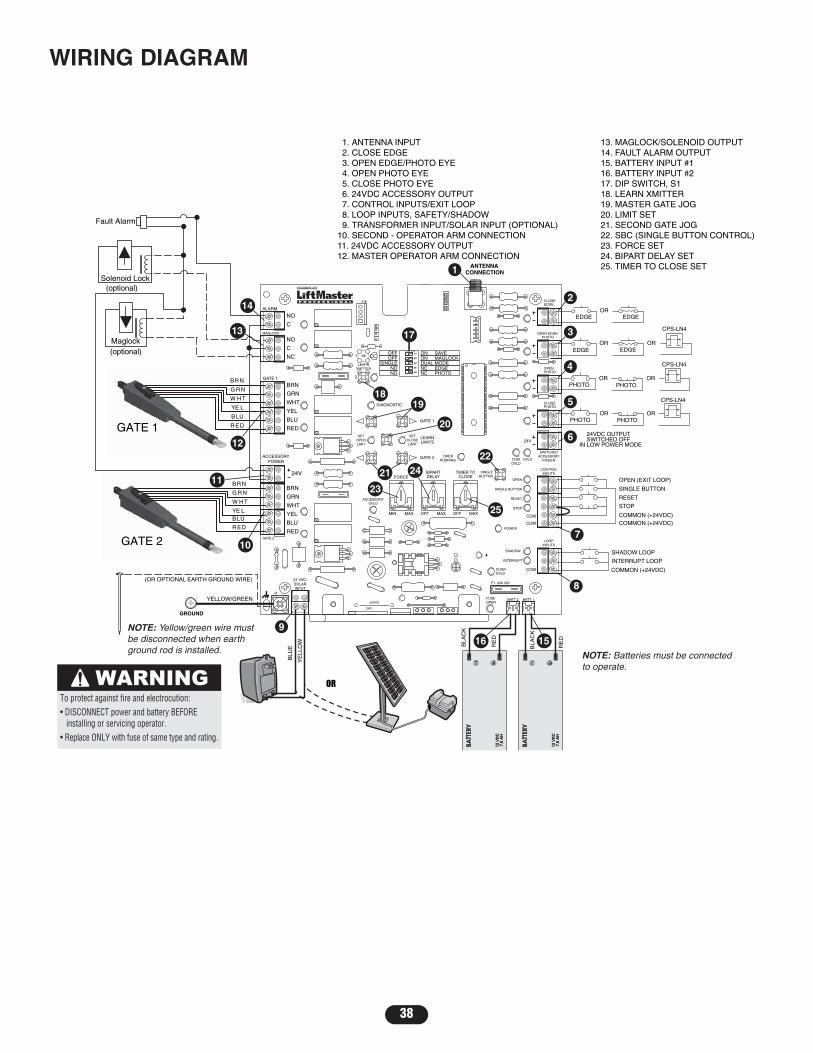
38
Z22
R91
CLOSEEDGE
R94
R92
R93
L1
R1
R2
Z1
K5
K2
F3
10A 32V
D1ÿ
OPEN EDGE/PHOTO
OPENPHOTO
CLOSEPHOTO
J18
R227
R2ÿ 7
Z2ÿ
R223
P1
Z9
Z8
F2
F6
D4
D2
R9
C64JMPR1
R224
U4
P2
J1
J19
SINGLEBUTTON
CONTROLINPUTS
FORCEBIPARTDELAY
TIMER TOCLOSE
MIN MAX OFF MAX OFF MAX
OPEN
SINGLE BUTTON
RESET
STOP
SHADOW
S1
INTERRUPT
CHGROVLD
COM
COM
COM
FUSEOPEN
LOOPINPUTS
POWER
BATT 1BATT 2
F1 20A 32V
R35
D9
Z3
Z4
U3
D1
D27
F5
C11
C13
C12
D15C2R4
R1ÿ 1
R1ÿÿ
R9ÿ
Q9K1
R196
Q22
D8K3
K4
D21
D22 C4
ACCESSORYOVLD
D6
D6
JMPR2JMPR2
MOV1MOV2
DB1DB1U2
Z12
24 VAC/SOLARINPUT
GATE 2
MAGLOCK
ALARM
C
C
NC
NO
NO
GRN
WHT
YEL
BLU
RED
BRN
GRN
WHT
YEL
BLU
RED
BRNF4
10A 32V
F7
24V
24V
COMOVLD
OVLD
SWITCHEDACCESSORY
POWERTIMER
RUNNINGGATE 2
SETOPENLIMIT
SETCLOSELIMIT
LEARNLIMITS
DIAGNOSTIC
GATE 1
J4
SAVEMAGLOCKMODEEDGEPHOTO
OFFOFF
SINGLENONO
ONONDUALNCNC
LEARNXMITTER
S8
1 2 3 4 5ON
2
1
(optional)
Fault Alarm
Solenoid Lock
Maglock(optional)
ANTENNACONNECTION
YELLOW/GREEN
(OR OPTIONAL EARTH GROUND WIRE)
GROUND
G R N
W H T
YE L
BLU
R ED
BR N
GATE 1
G R N
W H T
YE LBLU
R ED
BR N
K6
EDGE EDGEOR
EDGE EDGEOR OR
PHOTO PHOTOOR OR
OR ORPHOTO PHOTO
CPS-LN4
24VDC OUTPUTSWITCHED OFF
IN LOW POWER MODE
OPEN (EXIT LOOP)
SINGLE BUTTON
RESET
STOP
COMMON (+24VDC)COMMON (+24VDC)
SHADOW LOOP
INTERRUPT LOOP
COMMON (+24VDC)
GATE 2
OR
RE
D
BLA
CK
RE
D
BLA
CK
BLU
E
YE
LLO
W
GATE 1
ACCESSORYPOWER
1. ANTENNA INPUT 2. CLOSE EDGE 3. OPEN EDGE/PHOTO EYE 4. OPEN PHOTO EYE 5. CLOSE PHOTO EYE 6. 24VDC ACCESSORY OUTPUT 7. CONTROL INPUTS/EXIT LOOP 8. LOOP INPUTS, SAFETY/SHADOW 9. TRANSFORMER INPUT/SOLAR INPUT (OPTIONAL)10. SECOND - OPERATOR ARM CONNECTION11. 24VDC ACCESSORY OUTPUT12. MASTER OPERATOR ARM CONNECTION
13. MAGLOCK/SOLENOID OUTPUT14. FAULT ALARM OUTPUT15. BATTERY INPUT #116. BATTERY INPUT #217. DIP SWITCH, S118. LEARN XMITTER19. MASTER GATE JOG20. LIMIT SET21. SECOND GATE JOG22. SBC (SINGLE BUTTON CONTROL)23. FORCE SET24. BIPART DELAY SET25. TIMER TO CLOSE SET
7
8
15
2
3
4
5
6
1
16
23
24
25
9
21
20
19
10
11
12
18
14
22
13 17
NOTE: Batteries must be connectedto operate.
NOTE: Yellow/green wire mustbe disconnected when earthground rod is installed.
To protect against fire and electrocution:• DISCONNECT power and battery BEFORE installing or servicing operator.• Replace ONLY with fuse of same type and rating.
CPS-LN4
CPS-LN4
WIRING DIAGRAM

39
OPERATOR IS DEADNo LED lights are on.
OPERATOR DOES NOTRUNUnit does not respond toany commands.
MOTOR DOES NOT RUNRelays “click” when radioor SBC signal is given, butthe operator does notmove.
GATE STOPS ANDREVERSES(Force Reversal)
RPM REVERSAL
GATE STOPSGate starts to run, thenstops and does notreverse.
GATE OPENS BUT DOESNOT CLOSE
Audible beeps (3 times)when command is given.
GATE’S DO NOTOPEN/CLOSE IN SYNC
GATE DOES NOTAUTOMATICALLY CLOSEAuto Close Timer notclosing gate.
ACCESSORY DEVICE NOTWORKING PROPERLY
1) No voltage to board. ➤ Battery must be >23V, AC or Solar needs to be connected.2) Bad control board. ➤ Replace control board.
1) Low/disconnected battery. ➤ Voltage must be >23V at battery connection.2) Remote not programmed. ➤ See Programming Remote instructions.3) STOP connection loose/disconnected. ➤ Check STOP connections.4) Constant Open Command ➤ Clear all Open/Safety devices from obstruction.
(Check LED’s).5) Limits not programmed correctly. ➤ See Programming Limits instructions.6) Bad control board. ➤ Replace control board.
1) Low Battery. ➤ Voltage must be >23V at battery connection.2) Cable wiring between control box and ➤ Check wiring on control board to arm, replace wire if needed.
operator arm disconnected or loose.3) Batteries not connected. ➤ Connect batteries.4) Bad motor. ➤ Replace motor.5) Bad control board. ➤ Replace control board.
1) Low battery. ➤ Voltage must be >23V at battery connection.2) Gate met an obstruction. ➤ Clear gate from obstruction.
1) Constant Open Command ➤ Clear all Open/Safety devices from obstruction.(Check LED’s).
2) Timer to Close not set. ➤ See Timer to Close section for adjustment instructions.3) Accessory device wired to Open Only ➤ Rewire desired accessory device to Single Button Input.
command.
FAULT POSSIBLE CAUSE FIX
TROUBLESHOOTING
1) Obstructed Arm (bottoms out). ➤ Check for obstruction on arm, verify arm is not bottomed out.2) Bad RPM Sensor. ➤ Replace arm.3) Too much mA pulled off board. ➤ Move accessories to separate power source. Use reference chart on
next page to determine max mA draw for circuit board.
1) Battery Low >23.5V ➤ Operator will resume normal operation once battery voltage reaches 24V.
1) Bi-Part Delay not set. ➤ See Bi-Part Delay section for adjustment instructions.2) Limits not programmed correctly. ➤ See Programming Limits section for instructions.3) Incorrect Arm Installation ➤ See Installation section for instructions.
1) Timer to Close not turned on. ➤ See Timer to Close section for instructions.2) Gate has opened on Obstruction ➤ Check DIAG code, clear obstruction.
Reversal.3) Operator in “Party Mode”. ➤ Use Remote/SBC to resume normal operation.4) Constant Open Command ➤ Clear all Open/Safety devices from obstruction.
(Check LED’s).
1) Gate met an obstruction. ➤ Clear gate from obstruction.2) Force set too low. ➤ See Force Adjustment section.3) Bad gate hardware. ➤ Service/replace gate hardware.4) Incorrect Arm installation. ➤ See Installation section of operator arm.
1) Not installed properly. ➤ Check for proper installation of accessory.2) Enabling Switch not turned on. ➤ Turn applicable switches on.3) Loose/disconnected wires. ➤ Check proper installation of wires.4) Bad accessory device ➤ Replace accessory device.

40
DIAGNOSTIC CODES
# OF BLINKS MEANING1 No Stop Switch Connected2 Gate 1 Arm Disengaged3 Gate 2 Arm Disengaged4 Both Gate Arms Disengaged5 RPM Reversal6 Force Reversal7 Processor Reset8 ROM Check Failed9 RAM Check Failed10 EEPROM Check Failed - Reset Limits
MAX CURRENT DRAW115 power to control box - 500mA accessory power, 150mA switched
accessory power.
24V power to control box depending on wire gauge and distance - 300mAaccessory power, 75mA switched accessory power.
Solar power to control box - 0mA accessory, 50mA switched accessorypower.

41
8
2 7
4 6
5
3
1
Refer to the parts lists below for replacement parts available for your operator. If optional modifications and/oraccessories are included with your operator, certain components may be added or removed from these lists.
CONTROL BOX LA400-CONT
ITEM PART # DESCRIPTION QTY1 K001A6039 Control Board 12 K75-15480 Control Box & Cover
with Gasket 13 K75-30764 Control Board Bracket 14 K23-19380 Reset Switch 15 K74-19499 Antenna 16 K74-30762 Battery 27 K74-30763 Transformer 18 K76-19446 Alarm 1
Not Shown K74-30941 ATC Fuse Kit Includes20 Amp (1), 15 Amp (2)
K001A5747-2 390 MHz Receiver ModuleK001A5747 315 MHz Receiver Module
REPAIR PARTS

42
1
2
3
4
ACTUATOR ARM KITS
ITEM PART # DESCRIPTION QTY1234
Not Shown
Release LeverMotor with Limit Switch HarnessRear ConnectorCable 24V with ConnectorRelease KeyHardware BagComplete With: Gate bracket, Postbracket, Extension bracket and Hardware
111111
41ASWG-442SA41ASWG-438SA41ASWG-0014SA41ASWG-48941ASWG-0119K77-19130

OPEN OPEN
43
1-Button Station:Steel enclosure wired station will allow fora Open, Close, Stop command of the gate.
377LM
02101
370LM
373LM
Gate Solenoid Lock:Heavy all steel construction. Failsafe operationkeeps gate locked if power is lost. Can bewelded onto gate or post. 24Vdc operation,solenoid-activated release. Can be released in case of an emergency. Requires separatepower supply (Model ARMPS).
GC824-12
LM202 Vehicle Detecting Driveway Probe:One piece outdoor buried vehicle motiondetector with sensing probe is housed in asmall relay type housing. Provides for free exit.
SOLKIT12V (Single Panel)SOLKIT12V-2P (Two Panels):Kit contains: Battery management module,outdoor battery case (battery not included),solar panel(s). When power is not close by,solar may be the right option. For moreinformation, please contact customer serviceor see pre-sale solar application guide.
SOLKIT12V
3-Button SECURITY✚® RemoteControl :Includes visor clip.
SECURITY✚® Keyless Entry :Enables homeowner to operate gate by enteringa password on a specially designed keyboard.Also can add a temporary password for visitorsor service persons. This temporary passwordcan be limited to a programmable number ofhours or entries.
3-Button Mini-Remote Controlwith SECURITY✚® :With key ring and fastening strip.
OPEN
OPEN OPEN
OPEN
OPEN
OPEN
OPEN
OPEN
86LM Remote Antenna Mounting Kit:Kit contains antenna bracket and 15' (4.6 m)of cable. Recommended for increasing theeffective range of remote controls.
GC838 Magnetic Gate Lock:Incredible 1,200 Lb. holding force. Operates on 12 or 24Vdc. Low power consumption.Universal mounting holes for ease ofinstallation. Automatically releases when power is lost. Requires separate power supply(Model ARMPS).
50-19509 6" Post Mounting Kit for control box
50-19511 4" Post Mounting Kit for control box
50-19512 2 1/2" Post Mounting Kit for control box
50-19503 Push to Open BracketUsed to allow the gate operator topush the gate open.
OPEN
LA400 SWING GATE ACCESSORIES
GCPSN4
CPS-LN4
Commercial Protector System®:Maximum range is 45' 24V. Includes mountinghardware and electrical interface box.
Commercial Protector System® (DirectConnect):Maximum range is 45' 24V. Includes mountinghardware.

HOW TO ORDER REPAIR PARTSOUR LARGE SERVICE ORGANIZATION
SPANS AMERICAFOR INSTALLATION AND SERVICE INFORMATION,
CALL OUR TOLL FREE NUMBER
1-800-528-2806
www.liftmaster.com
WHEN ORDERING REPAIR PARTSPLEASE SUPPLY THE FOLLOWING INFORMATION:PART NUMBER DESCRIPTION MODEL NUMBER
ADDRESS ORDER TO:
THE CHAMBERLAIN GROUP, INC.Technical Support Group
6050 S. Country Club RoadTucson, AZ 85706
© 2008, The Chamberlain Group, Inc.01-19244E All Rights Reserved
LIFTMASTER® TWO YEAR LIMITED WARRANTYThe Chamberlain Group, Inc. warrants to the first purchaser of this product, for the structure in which this product is originallyinstalled, that it is free from defect in materials and/or workmanship for a period of two years from the date of purchase. The properoperation of this product is dependent on your compliance with the instructions regarding installation, operation, maintenance andtesting. Failure to comply strictly with those instructions will void this limited warranty in its entirety.If, during the limited warranty period, this product appears to contain a defect covered by this limited warranty, call 1-800-528-2806,toll free, before dismantling this product. Then send this product, pre-paid and insured, to our service center for warranty repair. Youwill be advised of shipping instructions when you call. Please include a brief description of the problem and a dated proof-of-purchasereceipt with any product returned for warranty repair. Products returned to Seller for warranty repair, which upon receipt by Seller areconfirmed to be defective and covered by this limited warranty, will be repaired or replaced (at Seller’s sole option) at no cost to youand returned pre-paid. Defective parts will be repaired or replaced with new or factory-rebuilt parts at Seller’s sole option.ALL IMPLIED WARRANTIES FOR THE PRODUCT, INCLUDING BUT NOT LIMITED TO ANY IMPLIED WARRANTIES OFMERCHANTABILITY AND FITNESS FOR A PARTICULAR PURPOSE, ARE LIMITED IN DURATION TO THE TWO YEAR LIMITEDWARRANTY PERIOD SET FORTH ABOVE, AND NO IMPLIED WARRANTIES WILL EXIST OR APPLY AFTER SUCH PERIOD. SomeStates do not allow limitations on how long an implied warranty lasts, so the above limitation may not apply to you. THIS LIMITEDWARRANTY DOES NOT COVER NON-DEFECT DAMAGE, DAMAGE CAUSED BY IMPROPER INSTALLATION, OPERATION OR CARE(INCLUDING, BUT NOT LIMITED TO ABUSE, MISUSE, FAILURE TO PROVIDE REASONABLE AND NECESSARY MAINTENANCE,UNAUTHORIZED REPAIRS OR ANY ALTERATIONS TO THIS PRODUCT), LABOR CHARGES FOR REINSTALLING A REPAIRED ORREPLACED UNIT, OR REPLACEMENT OF BATTERIES.THIS LIMITED WARRANTY DOES NOT COVER ANY PROBLEMS WITH, OR RELATING TO, THE GARAGE DOOR OR GARAGE DOORHARDWARE, INCLUDING BUT NOT LIMITED TO THE DOOR SPRINGS, DOOR ROLLERS, DOOR ALIGNMENT OR HINGES. THISLIMITED WARRANTY ALSO DOES NOT COVER ANY PROBLEMS CAUSED BY INTERFERENCE. ANY SERVICE CALL THATDETERMINES THE PROBLEM HAS BEEN CAUSED BY ANY OF THESE ITEMS COULD RESULT IN A FEE TO YOU. UNDER NO CIRCUMSTANCES SHALL SELLER BE LIABLE FOR CONSEQUENTIAL, INCIDENTAL OR SPECIAL DAMAGES ARISING INCONNECTION WITH USE, OR INABILITY TO USE, THIS PRODUCT. IN NO EVENT SHALL SELLER’S LIABILITY FOR BREACH OFWARRANTY, BREACH OF CONTRACT, NEGLIGENCE OR STRICT LIABILITY EXCEED THE COST OF THE PRODUCT COVERED HEREBY.NO PERSON IS AUTHORIZED TO ASSUME FOR US ANY OTHER LIABILITY IN CONNECTION WITH THE SALE OF THIS PRODUCT.Some states do not allow the exclusion or limitation of consequential, incidental or special damages, so the above limitation orexclusion may not apply to you. This limited warranty gives you specific legal rights, and you may also have other rights which varyfrom state to state.
WARRANTY POLICY AND SERVICE