i MASSAHIUSETTS INSTITUTE i! Multivehicle Simulation ...
39
AASSACHU TSEI-S IN TITUT i i NOV 13 2008 i! Multivehicle Simulation System by Greg H. Belote MASSAHIUSETTS INSTITUTE OF TECHNOLOCy j NOV 13 2008 LIBRARIES Submitted to the Department of Electrical Engineering and Computer Science in partial fulfillment of the requirements for the degree of Master of Engineering in Computer Science and Engineering at the MASSACHUSETTS INSTITUTE OF TECHNOLOGY June 2008 @ Massachusetts Institute of Technology 2008. All rights reserved. I A u thor .......... ............... .-........ ....................... Department of Electrical Engineering and Computer Science May 23, 2008 Certified by............... John J. Leonard Professor Thesis Supervisor Accepted by..... ( Arthur C. Smith Chairman, Department Committee on Graduate Theses ARCHIVES
Transcript of i MASSAHIUSETTS INSTITUTE i! Multivehicle Simulation ...

AASSACHU TSEI-S IN TITUT i
i NOV 13 2008i!Multivehicle Simulation System
by
Greg H. Belote
MASSAHIUSETTS INSTITUTEOF TECHNOLOCy j
NOV 13 2008LIBRARIES
Submitted to the Department of Electrical Engineering and ComputerScience
in partial fulfillment of the requirements for the degree of
Master of Engineering in Computer Science and Engineering
at the
MASSACHUSETTS INSTITUTE OF TECHNOLOGY
June 2008
@ Massachusetts Institute of Technology 2008. All rights reserved.
I
A u thor .......... ............... .-........ .......................Department of Electrical Engineering and Computer Science
May 23, 2008
Certified by...............John J. Leonard
ProfessorThesis Supervisor
Accepted by..... (Arthur C. Smith
Chairman, Department Committee on Graduate Theses
ARCHIVES


Multivehicle Simulation System
by
Greg H. Belote
Submitted to the Department of Electrical Engineering and Computer Scienceon May 23, 2008, in partial fulfillment of the
requirements for the degree ofMaster of Engineering in Computer Science and Engineering
Abstract
In this thesis, we designed and implemented a simulator that supports multiple robotswithin a dynamic environment. The goal of this tool is to provide a testing environ-ment for navigational robots that run on the MOOS platform. The simulator iswritten in C++ and utilizes several open source libraries to create a virtual world forrobots to interact with by faking sensor information.
A design goal of this thesis has been to make the simulator versatile enough to beuseful for a variety of robots, from land to marine. Such a tool is valuable in researchbecause the cost of developing a custom simulator can consume too many man-hours.Reducing this cost by creating a generic and customizable simulator has been themain motivation behind this thesis. It has also been one of the major challengesbehind the project.
Thesis Supervisor: John J. LeonardTitle: Professor


Acknowledgments
I would like to thank John Leonard for taking me in and for his support in my project.
I would also like to thank my friends and family for their support throughout the
years.
Finally I would like to thank the open source community for providing such a
wonderful collection of software and tools that I use every day.


Contents
1 Introduction 11
1.1 M otivation . . . . . . . . . . . . . . . . . . . . . . . . . . . . . . . . . 11
1.1.1 Cooperative Navigation ..................... 12
1.2 M O O S . . . . . . . . . . . . . . . . . . . . . . . . . . . . . . . . . . . 13
1.3 Related W ork ............................... 13
1.3.1 MOOS Simulators ........................ 13
1.3.2 Player Project ........................... 14
1.3.3 CARM EN ............................. 14
1.4 Sum m ary ................................. 14
2 Design and Implementation 17
2.1 Visualization ............... ............. ... 18
2.2 Physics . . . . . . . . . . . . . . . . . . . . . . . . . . . . . . . . .. . 19
2.2.1 PartFactory ............................ 19
2.2.2 PhysicsController ......................... 20
2.3 Robot and Device Representation . . . . . . . . . . . . . . . . . . . . 20
2.3.1 Wheel/Motor Device ........... ...... ..... .. 22
2.3.2 Laser Rangefinder ......................... .22
2.3.3 Swarm Position Sensor ...................... .23
2.4 MOOS Integration ........... ......... ....... . 23
2.5 Configuration ....................... . ...... . 25
2.5.1 Parsing . . . . . . . . . . . . . . . . . . . . . . . . . . . . . . 26
7

3 Conceptual Design
3.1 World Configuration v2.0 ...
3.1.1 Robot configuration..
3.1.2 Active objects .....
3.1.3 Terrain..........
3.1.4 Noise Injection . . . .
3.2 Additional Devices ......
3.2.1 Acoustic Modem . . .
3.2.2 Bumper sensors . ...
3.2.3 Inertial sensors . ...
3.2.4 GPS sensor ......
3.3 Underwater mode .......
3.3.1 Naive underwater mode
3.3.2
3.4 ODE
3.4.1
Simulated buoyancy/drag underwater mode
Optimization ..................
Time control .................
4 Conclusions
4.1 Summary ......................
4.2 Applications . . . . . . ..................
4.2.1 Multi-vehicle cooperative land navigation . .
4.2.2 Multi-vehicle cooperative underwater navigation
4.2.3 Long term SLAM in a dynamic environment .
4.2.4 Ranger underwater robot .............
A Sample Configuration File
. . . . . . ... . .
.. ... . .... . .. .
.. .. . . . . . . .
...........
. . . . . . . . . . .
...........
. . . . . . . . . . .
. . . . . . . . . . .
. . . . . . . . . . .
...........
...........
. . . . . . . . . . .
29
29
29
30
30
30
30
31
31
31
31
32
32
32
33
34
List of Figures
1-1 Land robot sensing nearby objects. . ................... 12
1-2 Multiple surface robots cooperatively navigate with underwater robots.
[11] . . . . . . . . . . . . . . . . . . . . . . . . . . . . ... .. . . . . . . 13
2-1 Back-end overview. ............................ 17
2-2 Example scenegraph tree. (a) is a the scenegraph representation of (b). 19
2-3 Diagram of a Part. ............................ 20
2-4 Flow of information. ........................... 21
2-5 Structure of a robot and the components that define it. ......... 22
2-6 The MOOSAdapter creates an internal CMOOSApp that communi-
cates with the MOOSDB. ........................ 23
2-7 Sequence diagram of the creation of a MOOS Adapter. ........ . 24
2-8 Sequence diagram of message publishing via notify. .......... 26
2-9 Sequence diagram of message retrieval via getMail. .......... . 27
2-10 The world builder takes a configuration file as input and generates
objects in the world. ........................... 28


Chapter 1
Introduction
This thesis presents the initial design for a versatile simulation tool for robotic sys-
tems. Originally it began as a widely scoped project to connect virtual machines
running robot code to a flexible simulator engine, but gradually the focus narrowed
to become a simulator for MOOS-powered robots. It creates a dynamic physics en-
vironment and models sensor data to present a world that appears real from the
perspective of the robot. The design goal of this system is to create a simulation
framework that provides a transparent environment for the robot, while being mod-
ular enough to be useful for multiple research projects.
It uses the OpenDynamics Engine [131 for the back-end physics representation,
Simple DirectMedia Layer [3] for user event handling, and OpenGL [2] for rendering.
1.1 Motivation
Some challenges in robotic research include dealing with faulty hardware, running
potentially costly (in time, money, and personnel) experimentation, and being unable
to observe/interact with the robot while in it's environment.
The use of simulation can improve the productivity of a researcher/developer.
It circumvents the need for an actual robot, allowing for more parallelism between
colleagues. It also provides a more controlled environment, something not always
available in the real world.

Figure 1-1: Land robot sensing nearby objects.
It's not always worthwhile for a research team to develop a simulator-there may
not be enough time or manpower available for it's design and implementation. Simu-
lators are notorious for being too idealistic, which can make them mostly useless for
late-stage development and thus not worth the development cost to produce.
The motivation of this project is to create a useful simulation tool that can be
used for a variety of robotic research projects with minimal cost of use.
1.1.1 Cooperative Navigation
In the field of multivehicle, cooperative navigation there is a need for good simulation
tools. This is especially true for marine robotics, where the cost of experiments are
high and often behavior cannot be fully observed.
One research project explores the use of multiple surface vehicles assisting an
underwater robot navigate. Underwater navigation is difficult because there does not
exist a practical technology for using GPS underwater. With the added complexity of
water currents causing the robot to drift it is difficult for robots to localize themselves.
Figure 1-2 illustrates one solution. Two surface robots use GPS to compute their
location and broadcast this information using an acoustic modem. Robots under
water can then triangulate their location relative to the surface robots,

Figure 1-2: Multiple surface robots cooperatively navigate with underwater robots.
[11]
1.2 MOOS
The Mission Oriented Operation Suite [12] is a software library designed for mo-
bile robotic research. It offers an array of tools for multi-platform communication,
navigation and path planning, mission task management, and mission logging and
playback. It is useful for collaboration between researchers because it allows for the
development of software modules without the need to share source code. Rather every
research group uses the same core MOOS library. This helps each group to develop
concurrently by reducing errors related to module dependency and integration.
1.3 Related Work
1.3.1 MOOS Simulators
Some tools already exist for simulating robots that use MOOS, such as iMarineSim
[5] and iRobotSim [6]. iMarineSim is a simple underwater vehicle simulator that
generates robot position information using old position values and integrating with
actuator values (rudder, thrust, and elevator). The implementation is simple and it is

helpful for some experiments in navigation. iRobotSim is a similar simulator except
for land robotics. Given the previous position and actuator values, it will compute a
new position and broadcast over MOOS.
1.3.2 Player Project
The Player Project [4] is an open source project for research robotics. It supports
multiple 2d and 3d land robots along with sensors such as sonar, laser rangefinders,
pan-tilt-zoom cameras, and odometry with network device interface.
At the beginning of the project we considered the use of Player and Gazebo [4] as
a back-end simulation engine. The main reason we choose not to do this was because
we wanted a simulator that could eventually support underwater robots, but Gazebo
is exclusively land-based. Additionally we needed the flexibility to simulate acoustic
modems, which isn't supported either. Minor reasons include the desire to integrate
MOOS into the simulator and to potentially support communications with a virtual
machine, which may require more flexibility within the engine than available.
1.3.3 CARMEN
CARMEN [1] is the Carnegie Mellon Robot Navigation Toolkit and is an open-source
suite of software for mobile robot control. Like MOOS it provides tools for robot
control, logging, obstacle avoidance, localization, path planning, and mapping. How-
ever it is written in C (and has Java bindings) and uses a different mechanism for
intermodule communication. Built into CARMEN is a robot and sensor simulator
for 2d robotics.
1.4 Summary
This thesis presents the conceptual design and initial implementation of a flexible and
powerful multiple vehicle simulation environment to support research in cooperative
navigation and autonomy for marine and land robots using MOOS.

Chapter 2 describes the current state of the project, it's design, and how the mod-
ules are implemented. Chapter 3 discusses the conceptual design of where we want
the project to go, and a variety of modifications and extensions to the functional-
ity. Chapter 4 summarizes this paper and describes ways that the simulator can be
applied to existing robotic research.

Chapter 2
Design and Implementation
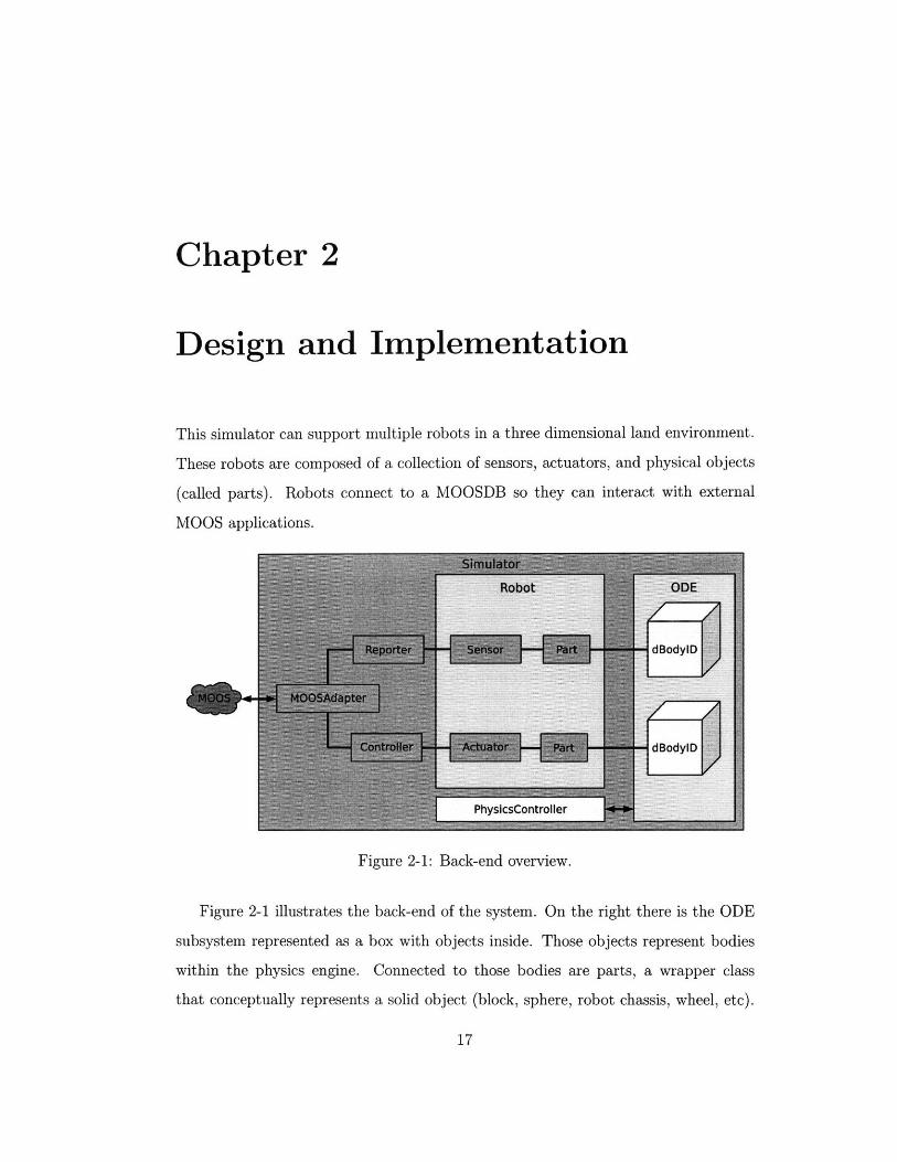
This simulator can support multiple robots in a three dimensional land environment.
These robots are composed of a collection of sensors, actuators, and physical objects
(called parts). Robots connect to a MOOSDB so they can interact with external
MOOS applications.
Figure 2-1: Back-end overview.
Figure 2-1 illustrates the back-end of the system. On the right there is the ODE
subsystem represented as a box with objects inside. Those objects represent bodies
within the physics engine. Connected to those bodies are parts, a wrapper class
that conceptually represents a solid object (block, sphere, robot chassis, wheel, etc).

Sensors and actuators are usually connected to parts so they can interact with the
world. A robot is defined as a collection of sensors, actuators, and parts.
Sensors and actuators are connected to reporters and controllers, whose responsi-
bility is to handle communication with MOOS via the MOOSAdapter. The MOOSAdapter
is connected externally to a MOOS community.
The PhysicsController interacts with ODE for updates and custom collision de-
tection handling.
2.1 Visualization
The simulator's visualizer uses a scene graph model to render the virtual world. A
scene graph is a tree-like directional graph of nodes, where each node represents a
step in the rendering process. During while rendering the graph is traversed starting
at the root. Each node can apply operations to screen, some change the state for
child nodes (like matrix transforms). Figure 2-2 shows an example scene graph (a)
and an example rendering (b). The renderer starts at the root node (i) and walks the
tree. Nodes are numbered with roman numerals in order they are traversed.
When most physical objects (such as a block) are built, they will attach nodes to
the rendering tree that render the particular component.
For example, the SimplePartFactory (which is an object responsible for building
basic shapes) will generate physical shapes within ODE and create nodes to render
these shapes. It attaches two nodes to the rendering tree--one node applies a trans-
form matrix based on the object's position in the world, and the other will draw the
shape as if it were located at the origin.
The tree is stored in a RenderModel object stored within the RenderController.
The controller is responsible for managing the updating and rendering of the tree. At
the root of the tree is a Camera node, which has several different modes of viewing.

(a) (b)Figure 2-2: Example scenegraph tree. (a) is a the scenegraph representation of (b).
2.2 Physics
Physics simulation is handled by the ODE library almost entirely. The exception is
collision handling; there are special objects that use collision callbacks to produce
sensor information.
There are two important classes that wrap ODE for other modules: Part and
PhysicsController. A Part object serves as a handle to a physical object and connects
it to a rendering node for visualization. The PhysicsController handles updating of
the world and custom collision handing.
Figure 2-3 illustrates a Part object. It is connected to a body within the ODE
subsystem and a Node within the rendering subsystem.
2.2.1 PartFactory
We decouple the construction of Parts from other modules in the simulator with the
PartFactory. A PartFactory is based on the Abstract Factory design pattern [8].
The factory can generate basic shapes, such as spheres and boxes, and the style of

Figure 2-3: Diagram of a Part.
visualization depends on the factory implementation.
Constructing a Part involves creating geoms and bodies within ODE and attachingNodes to the scene graph.
2.2.2 PhysicsController
The PhysicsController functions as a placeholder for ODE handles, controller forphysics updating, and special collision handling dispatching.
The OpenDynamics Engine allows for user callback functions to be called that help
resolve potential collisions within the world, and these callbacks can notify ODE about
how to handle the potential collision. Such a system is very useful for implementing
sensors. For example the laser rangefinder is able to record laser travel distances with
the location of the collision point and tell ODE to allow the laser to pass through
that object, all using the callback interface.
To register a callback a CollideCallback object should be set as the user data
for geom with dGeomSetData. Whenever that geom intersects another geom, the
PhysicsController will call a collide method within CollideCallback.
2.3 Robot and Device Representation
A robot consists of physical parts (a chassis and wheels, for instance) and a collection
of devices (actuators and sensors). During construction, a generic Robot class is

created and sensors, actuators, and parts are attached to the robot.
Sensors and actuators handle the interaction with the physics subsystem, while
SensorReporters and ActuatorControllers handle message generation and parsing.
Analogous to the Model-Controller-View paradigm, sensors/actuators act as models,
reporters act as viewers, and controllers act as controllers. For each Sensor and
Actuator there exist implementations of SensorReporter and ActuatorController that
interact with MOOS via the MOOSAdapter object (see 2.4).
Figure 2-4 illustrates a generic control loop for the robot. Messages from the
MOOS realm come in and are stored in the MOOSAdapter. An ActuatorController
can get these messages, parse them, and send commands to an Actuator (such as
a motor), the Actuator translates the command into operations within the physics
package. ODE processes a step in the physics simulation and sensors read information
from the world. The SensorReporter gets sensor data from the Sensor object and
converts it into a MOOS message. This message is then sent to the MOOSAdapter
which will then publish the message to the MOOSDB.
SensorReporter MOOSAdapter ActuatorController
Sensor physics Actuator
Figure 2-4: Flow of information.
Figure 2-5 shows object containment. A Robot object contains zero or more parts,
sensors, and actuators. Some sensors and actuators are anchored to parts. SensorRe-
porters are each connected to one Sensor (as ActuatorControllers are to Actuators).
SensorReporters and ActuatorControllers are also connected to a MOOSAdapter.

•--B
las 0+ B
has 1 Bhas 1 B
I I
Figure 2-5: Structure of a robot and the components that define it.
2.3.1 Wheel/Motor Device
There is a fairly simple implementation for motor controlled wheels and a differential
drive train. ODE allows the user to create joints that connect object bodies in the
simulated world, and there exist special joints that function as motors. A Wheel ob-
ject wraps this functionality and provides an interface to set wheel velocities and read
wheel positions. This is then used by a DifferentialDriveTrain object to control two
wheels that can be driven with an interface that allows thrust and rudder velocities
to be set. An Odometry object can be attached to the two wheels in the drive train
in order to produce estimated X,Y,O coordinates, similar to an odometry system that
counts wheel ticks.
2.3.2 Laser Rangefinder
This device is implemented by creating rays and testing their closest intersection. An
array of rays are attached to a base object, and then collision callbacks are set for the
physics engine to call whenever a ray intersects another object. Within this callback
the rangefinder will record which ray collided and record the closest intersection.
Once the physics updating is complete, the rangefinder will generate an array of
I/

distances for that world snapshot. This can then be used to render the device and
report a LASERRANGE message to MOOS.
2.3.3 Swarm Position Sensor
The swarm position sensor is a device that reports the relative and absolute positions
of each other robot in the world. This device was written for use on cooperative
navigation between multiple robots.
2.4 MOOS Integration
We integrate the MOOS communication system directly into the simulator with the
MOOSAdapter class. The MOOSAdapter creates an internal MOOS application
(subclass of CMOOSApp) that connects externally to MOOS (see Figure 2-6). Re-
quests to the MOOSAdapter for sending and getting MOOS messages are forwarded
to the internal app for handling.
MOOS Realm Simulator Realm
Figure 2-6: The MOOSAdapter creates an internal CMOOSApp that communicates
with the MOOSDB.
Due to the need for CMOOSApp to take control and run it's own event loop, the
internal MOOS app is run within it's own thread.
Upon creation it uses pthreads [7] to create a new thread and hand control to the
Run method inherited from CMOOSApp. Figure 2-7 illustrates the creation process
with a sequence diagram. Since a MOOS app must register to message channels
during setup, the MOOSAdapter doesn't connect until start is called. During the
II
I
III

period before start, objects can ask the MOOSAdapter to register to a given channel
by calling subscribe and passing the channel name. The adapter will place the name
on a queue, and will subscribe when connecting to the server.
When start is called the adapter forwards the request to the internal app, which
creates a new thread using the pthreads library. The new thread calls dispatch in
the internal app, which will then call Run (a CMOOSApp method) on itself. Run
will seize control of the thread and not return until the app is terminated.
subscribe
Figure 2-7: Sequence diagram of the creation of a MOOS Adapter.
To prevent race conditions mutex locks are used to handle data passing between
the MOOS and simulator threads. To minimize blocking time locks are only held
for quick copying of information, allowing the bulk of the task to be done while the
thread is not holding any locks.
Two important methods in MOOSAdapter are notify and getMail. Notify works
the same way as CMOOSApp::Notify-the caller passes a MOOS message name (such
as LASERRANGE) and data for that message (either a double or a string). The app
then sends this message to the MOOSDB to broadcast to all subscribers to messages
that share the given message name. See Figure 2-8 for a sequence diagram.
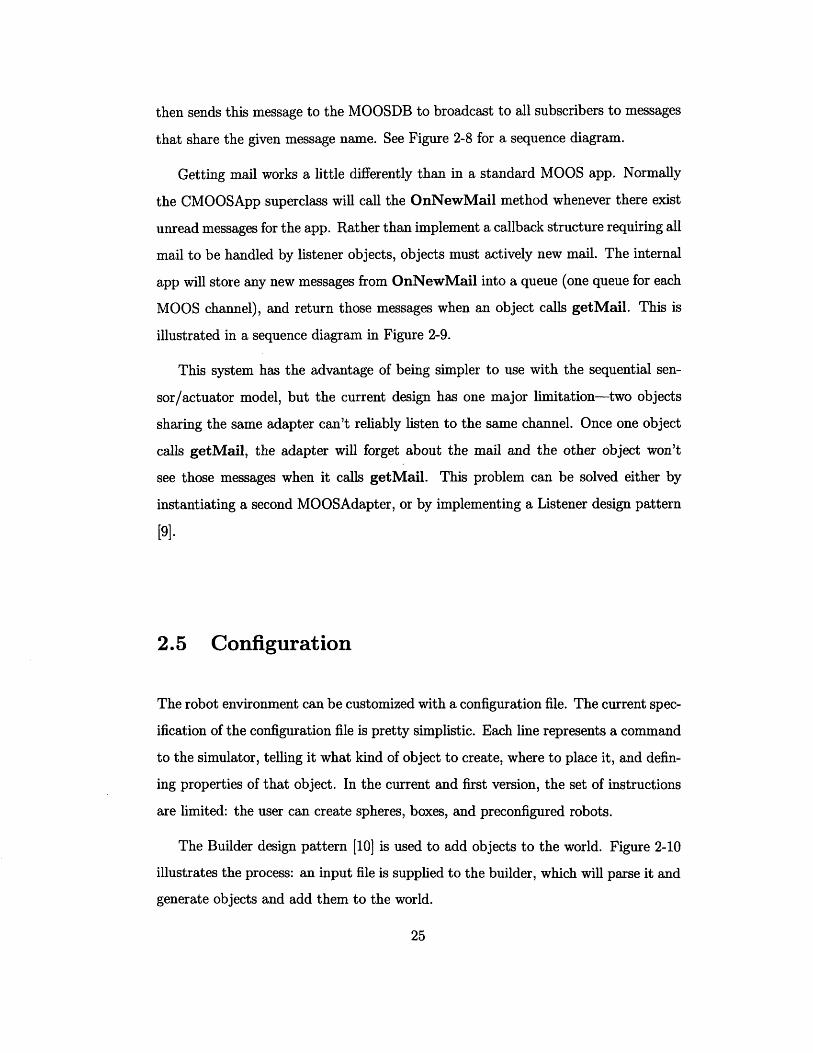
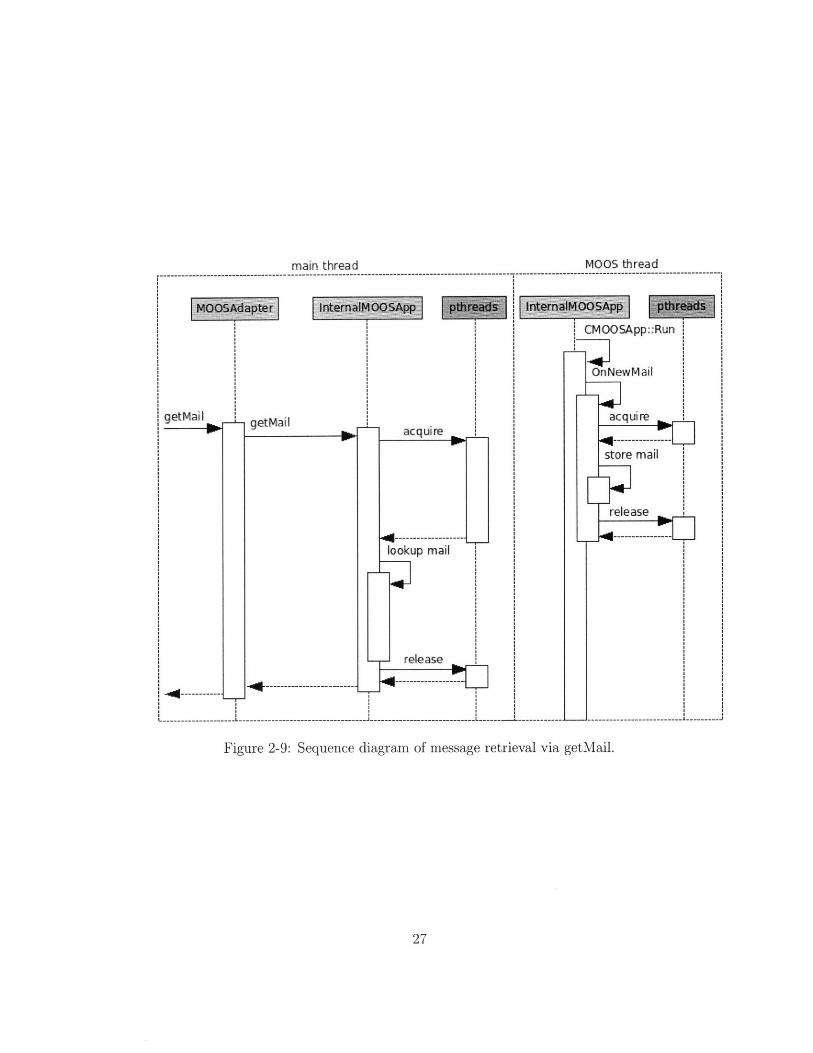
Getting mail works a little differently than in a standard MOOS app. Normally
the CMOOSApp superclass will call the OnNewMail method whenever there exist
unread messages for the app. Rather than implement a callback structure requiring all
mail to be handled by listener objects, objects must actively new mail. The internal
app will store any new messages from OnNewMail into a queue (one queue for each
MOOS channel), and return those messages when an object calls getMail. This is
illustrated in a sequence diagram in Figure 2-9.
This system has the advantage of being simpler to use with the sequential sen-
sor/actuator model, but the current design has one major limitation-two objects
sharing the same adapter can't reliably listen to the same channel. Once one object
calls getMail, the adapter will forget about the mail and the other object won't
see those messages when it calls getMail. This problem can be solved either by
instantiating a second MOOSAdapter, or by implementing a Listener design pattern
[9].
2.5 Configuration
The robot environment can be customized with a configuration file. The current spec-
ification of the configuration file is pretty simplistic. Each line represents a command
to the simulator, telling it what kind of object to create, where to place it, and defin-
ing properties of that object. In the current and first version, the set of instructions
are limited: the user can create spheres, boxes, and preconfigured robots.
The Builder design pattern [10] is used to add objects to the world. Figure 2-10
illustrates the process: an input file is supplied to the builder, which will parse it and
generate objects and add them to the world.

SensorReporter MOOSAdapter
:notify:notify
Figure 2-8: Sequence diagram of message publishing via notify.
2.5.1 Parsing
Using the standard C++ string stream library, a basic parser will iterate over every
line in the config file. For each line the parser will examine the first non-whitespace
character. If one does not exist (empty line) or it is a pound (#), the line is ig-
nored. Otherwise it will compare the first word (string preceding the next whitespace
character) with know commands, and dispatch to the appropriate command handler.
See Appendix A (Page 37) for an example.
: InternalMOOSApp : pthreadst
main thread
Figure 2-9: Sequence diagram of message retrieval via getMail.
MOOS thread
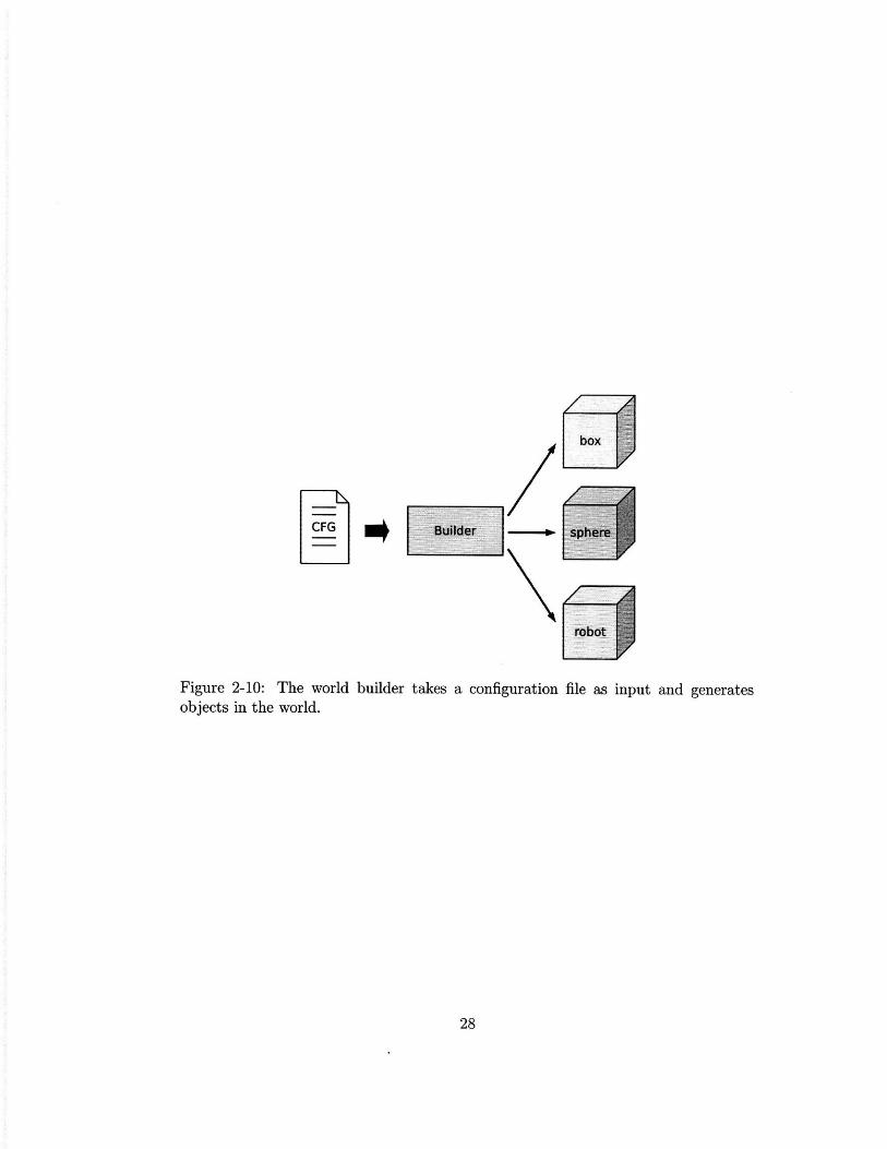
CFG
Figure 2-10: The world builder takes a configuration file as input and generatesobjects in the world.

Chapter 3
Conceptual Design
The previous chapter has described the basic functionality that has been implemented
and tested. This chapter presents the conceptual design of modules whose function-
ality is not yet implemented.
3.1 World Configuration v2.0
The current world configuration language is limited. While the language is sufficient
for placing simple objects in a world, extending the current parser to support more
complicated expressions will allow for more sophisticated experiments.
A new system should allow the user to do more than place pregenerated objects.
It should allow the setting of global parameters (such as global position for GPS) and
the creation of custom objects (such as an office chair).
XML is a powerful option for defining a world because of it's capabilities and
growing popularity.
3.1.1 Robot configuration
With the current system only robots defined within the source code can exist. There
is no real need for this, and it's a barrier for users with a robot whose shape does not
match what is hard-coded within the simulator.

XML can be used to describe the physical form of the robot, how it's parts are con-
nected, and even define it's sensors and actuators. A well designed and implemented
configuration system can be very powerful here.
3.1.2 Active objects
Another extension of the configuration system is to create active objects-things that
move around and the world based on pre-defined behavior. A basic class of active
objects are scripted active objects. They are configured to move at specific times or
when certain events occur.
3.1.3 Terrain
Currently the world is limited to existing on a completely flat, homogeneous surface
that extends forever in all directions. Such a limitation becomes significant when
dealing with robots that must traverse non-trivial terrain.
Currently the ground is represented as an infinite plane body within ODE. This
could easily be replaced with a mesh grid whose shape is defined by a configuration
file.
3.1.4 Noise Injection
Noise injection is another feature that belongs in the new configuration system. Cur-
rently sensors generate perfect information. By injecting random noise into a mea-
surement the simulator can better model the world. The user should be able to specify
the properties of this random noise distribution within the configuration file.
3.2 Additional Devices
Devices (sensors and actuators) are the heart of the simulator; they provide the main
functionality that make this a useful tool. The design of the system is around building

a library of sensors and actuators, and listed here are some that would be a valuable
addition.
3.2.1 Acoustic Modem
One non-trivial device that would be useful for an underwater simulator is the ability
to simulate an acoustic modem that takes into account range and perhaps even trans-
fer rate. The design we have for the modem is to create a special Unix file (device
or pipe) that any process can read and write do, but would be connected within the
simulator to a Modem object. The Modem object would then compute what other
Modem objects are in range -and listening on the same channel, then write to the
receiving modem's file descriptor data read from the first.
3.2.2 Bumper sensors
Bumpers are a very common and important sensor in robotics. To implement bumpers,
all that needs to be done is create a special physics object and connect to a callback
routine similar to the lasers in the laser rangefinder.
We'd like to create a sensor object that connects to one (or more) ODE geometry
object(s), allowing flexibility to create bumpers of many shapes.
3.2.3 Inertial sensors
Some robotic systems rely on inertial sensors like accelerometers and gyroscopes. The
implementation of an inertial sensor is straightforward in this system-request inertial
data for an ODE body during each physics update frame.
3.2.4 GPS sensor
A GPS sensor is a valuable sensor to have on almost any robot, and it should have
a place within this simulator environment. The implementation is straightforward-
request the absolute position of an object within ODE and compute the simulated

latitude and longitude. For this to work properly the user needs to be able to map a
point within the environment to a simulated latitude/longitude, which can be done
by adding an additional command (such as ANCHOR_GPS).
3.3 Underwater mode
The simulator lacks an underwater mode. There have been two ways we've been
considering implementing this feature, one naive and one that attempts to simulate
drag and buoyancy.
3.3.1 Naive underwater mode
The naive underwater mode would function similarly to iMarineSim: assume each
robot is floating in space and create actuators that push it around. This can be
accomplished by adding a configuration in the physics controller to disable gravity
and to add propeller actuators that control thrust, rudder, and elevation of the robot.
Such an implementation would be relatively simple to integrate into the simulator.
3.3.2 Simulated buoyancy/drag underwater mode
Buoyancy can be approximated by computing density using volume and mass. Dur-
ing each physics update the PhysicsController could apply a vertical force to each
object for buoyancy, assuming that object is under water. In order to prevent the
situation where objects bounce at the water's surface, immersion percentage should
be considered in the buoyancy calculation. Otherwise objects will oscillate at the
threshold of being "in" and "out" of water, since the buoyancy force will oscillate
from 100% to 0%.
Drag can be approximated with a drag coefficient, a velocity vector, and a cross-
sectional area of an object. The latter requires auxiliary code to be added.

3.4 ODE Optimization
There are a few optimizations that can be made to how we use ODE in order to
speed up the simulator. One performance bottleneck occurs when multiple laser
rangefinders are intersecting each other, and those rangefinders have a large number
of lasers (180, for instance).
The problem is that the collision detector must resolve n2 potential collisions (for
n lasers). Currently each laser is placed in the same Simple Space. A Space is an ODE
term for a 3d container where objects can exist. A Simple Space is an implementation
that performs a naive collision detection algorithm: it examines every possible pair
of objects for intersection. There exist other implementations such as a QuadTree
Space and Hash Space, both perform than O(n2) time (with rare exception).
Spaces can be nested within each other, allowing for further performance opti-
mizations. Doing this allows ODE to perform collision culling, reducing the number
of potential collision pairs. Placing each laser rangefinder (and it's set of laser rays)
within it's own space should improve performance. This does not reduce the prob-
lem of two close laser rangefinders facing each other: very little (if any) culling will
happen.
The use of category and collide bitfields can help performance. This feature of
ODE allows the us to define what can collide with what. So for instance we could
implement glass blocks that allow the laser rangefinder to see through them. The
use of category/collide bitfields can be used to prevent laser rangefinder spaces from
testing collisions, thus dealing with the case defined above.
Another way performance can be improved is with use of a faster world stepping
method. Currently dWorldStep is used for advancing the simulation forward by a
fixed amount of time, which consumes cubic time and quadratic memory. There are
faster but less accurate methods, such as dQuickStep and dFastStepl. Both allow the
user to trade speed for accuracy by defining iterations per step, resulting in a time
of O(N * m) where N is the number of iterations and m is the number of degrees of
freedom removed from the system. It should be noted that the use of a less accurate

world step routine can cause unexpected issues if some ODE global parameters are
not properly tuned.
3.4.1 Time control
Another feature is adding the ability to change the speed of time within the simulator.
Time control would be implemented within the event loop manager, by either skipping
physics updating (for pausing) or changing the way it synchronizes with real time (for
slowing down and speeding up). Unfortunately the ability to rewind would require
a large overhaul of the system, basically requiring the ability to reverse actions or
store a snapshot of the entire world state within ODE, as well as sensor and actuator
states.
Chapter 4
Conclusions
4.1 Summary
The simulation described in this thesis is a functional tool for testing multiple robots
within a land environment. This initial implementation is a starting point for a larger
and more versatile simulator that may become a valuable tool in research robotics.
This paper has outlined the project and it's direction for the future.
4.2 Applications
There are several specific applications that the simulator has been designed for.
4.2.1 Multi-vehicle cooperative land navigation
The simulator is designed to be used to simulate multiple land robots equipped with
only GPS and wireless modems to cooperatively navigate in an unknown environment.
It is assumed that two robots are equipped with GPS while the third is not, and robots
can determine the relative position of the others and transmit their coordinates.
This task can be accomplished by using the SwarmPositionSensor sensor, which
will sense the relative and absolute position of other robots in the swarm. The simu-
lator cheats a little in that it doesn't manage wireless communication over a modem

(assumes infinite broadcast radius) and that it doesn't compute GPS coordinates for
the robot but rather notifies it of absolute local coordinates.
4.2.2 Multi-vehicle cooperative underwater navigation
This application is very similar to the previously mentioned, except it takes place in
an underwater environment. The simulator currently lacks an underwater mode.
4.2.3 Long term SLAM in a dynamic environment
One project this simulator could be used for is a robot with a dynamically changing
environment for a long period of time. This application would require the development
of a dynamically reconfigurable world (such as scriptable objects) as well as a non-
MOOS method of communication.
4.2.4 Ranger underwater robot
With the addition of an underwater mode and a non-MOOS communication infras-
tructure, this simulator could be used with the Ranger project which requires devices
such as a GPS, sonar rangefinder, and inertial sensors.

Appendix A
Sample Configuration File
# Sample config script for setup
# This structure isn 't intended to be the long-term specification for the
# config , just an easy-to-implement format for the time being.
# command: CREATEROBOT
# syntax: CREATEROBOT <type> <x> <y> <theta> <moosFile>
# <types>: Type of robot to construct. Valid types: erl
# <x>: Starting X coordinate, in meters
# <y>: Starting Y coordinate, in meters
# <theta>: Start direction , in degrees [currently ignored]
# <moosFile>: MOOS config file for this robot , should be file path
CREATEROBOT erl 0 0 0 robol .moos
CREATE-ROBOT erl 4 4 0 robo2.moos
# command: CREATEBLOCK
# syntax: CREATEBLOCK <mass> <length> <width> <height> <x> <y> <theta>
# <mass>: Mass of block
# <length >: Length of block, in meters
# <width>: Width of block, in meters
# <height >: Height of block, in meters
# <x>: Starting X coordinate, in meters
# <y>: Starting Y coordinate, in meters

# <theta>:
# make walls
CREATEBLOCK
CREATEBI)LOCK
CREATEFBLOCK
CREATE.BLOCK
# make random
CREATE.BLOCK
Starting direction of block, in degrees [currently ignored
50 1
50 1
50 68.9
50 68.9
block
50 1 1
35 0 0
-35 0 0
4 0 -34.5
4 0 34.5
5 4 1 0
# command: CREATE-SPHERE
# syntax: CREATESPHERE <mass> <radius> <x> <y>
# <mass>:
# <radius >:
# <x>:
# <y>:
Mass of sphere
Radius of the sphere, in meters
Starting X coordinate , in meters
Starting Y coordinate , in meters
CREATESPHERE 25 1 -4 -4

Bibliography
[1] Carmen: Robot Navigation Toolkit. Website. http://carmen. sourceforge.net/.
[2] OpenGL. Website. http://www. opengl. org.
[3] Simple DirectMedia Layer. Website. http: //www. libsdl. org".
[4] The Player Project. Website. http://playerstage. sourceforge .net/.
[5] Michael R. Benjamin, Henrik Schmidt, and John Leonard. A Guide to theIvP Helm for Autonomous Vehicle Control, 2007. http://oceanai.mit. edu/mikerb/software/releases/ivputils_.DecO03_07_1235. pdf.
[6] M. Bosse, P. Newman, J. Leonard, and S. Teller. Simultaneous localization andmap building in large-scale cyclic environments using the Atlas framework. Int.J. Robotics Research, 23(12):1113-1139, December 2004.
[7] Ralf S. Engelschall. GNU Portable Threads. Website, 1999-2006. http://www.gnu. org/software/pth/.
[8] E. Gamma, R. Helm, R. Johnson, and J. Vlissides. Design Patterns: Elementsof Reusable Object-Oriented Software, pages 87-95. Addison-Wesley, 1995.
[9] E. Gamma, R. Helm, R. Johnson, and J. Vlissides. Design Patterns: Elementsof Reusable Object-Oriented Software, pages 293-302. Addison-Wesley, 1995.
[10] E. Gamma, R. Helm, R. Johnson, and J. Vlissides. Design Patterns: Elementsof Reusable Object-Oriented Software, pages 97-106. Addison-Wesley, 1995.
[11] John J. Leonard, Alexander Bahr, Joseph Curcio, and Andrew Patrikalakis.Towards Cooperative Navigation of Autonomous Underwater Vehicles and Au-tonomous Surface Vehicles.
[12] Paul Newman. Under the Hood of the MOOS Communications API. Web-site, 2007. http://www. robotics. ox. ac. uk/~pnewman/MOOSDocumentation/CommsArchitecture/latex/CommsArchitecture.pdf.
[13] Russell Smith. OpenDynamics Engine. Website, 2006. http: //www. ode. org/.