I lllm a - California Public Utilities...
26
I lllm a ENGINEERING a crest company Beta Engineering Telephone 318-487-9599 4725 Hwy 28 E Facsimile 318-442-1741 Pineville, LA 71360 www.BetaEngineering.com Engineering, Procurement & Construction of High Voltage Power Systems SUNCREST SUBSTATION SAN DIEGO GAS & ELECTRIC CO. BETA PROJECT NO. B537 GROUND GRID DESIGN BETA DOCUMENT NO. B537-GD REVISION 3 OCTOBER 21, 2011 I Designed by: ÿ'ÿ'ÿ" I Checked by: ÿ/ÿ [// Approved by:
Transcript of I lllm a - California Public Utilities...

I lllm aENGINEERING
a crest company
Beta Engineering Telephone 318-487-95994725 Hwy 28 E Facsimile 318-442-1741
Pineville, LA 71360 www.BetaEngineering.com
Engineering, Procurement & Construction of High Voltage Power Systems
SUNCREST SUBSTATIONSAN DIEGO GAS & ELECTRIC CO.
BETA PROJECT NO. B537
GROUND GRID DESIGN
BETA DOCUMENT NO. B537-GDREVISION 3
OCTOBER 21, 2011
I Designed by: ÿ'ÿ'ÿ" I Checked by: ÿ/ÿ [// Approved by:
TABLE OF CONTENTS
Grid Metrics & Design Results ............................................................................................................ 1-2 Touch/Step Calculations & Soil Resistivity Summary ........................................................................ 3-4 Traverse Results & Grounding Summary for 40kA Fault ................................................................... 5-6 Safety Report ........................................................................................................................................ 7-8 Ampacity Report 4/0 AWG ................................................................................................................. 9-10 Ampacity Report 500 MCM ................................................................................................................ 11-12 Plan View for Suncrest Substation Ground Grid ................................................................................. 13-14 User-Defined Touch Voltages for Suncrest Substation Ground Grid .................................................. 15-16 Safety-Limit Touch Voltages for Suncrest Substation Ground Grid ................................................... 17-18 User-Defined Step Voltages for Suncrest Substation Ground Grid ..................................................... 19-20 Safety-Limit Step Voltages for Suncrest Substation Ground Grid ...................................................... 21-22 Scalar Potential Profile for Suncrest Substation Ground Grid ............................................................. 23-24

Section Divider
This page intentionally left blank
1
B537 Suncrest Substation
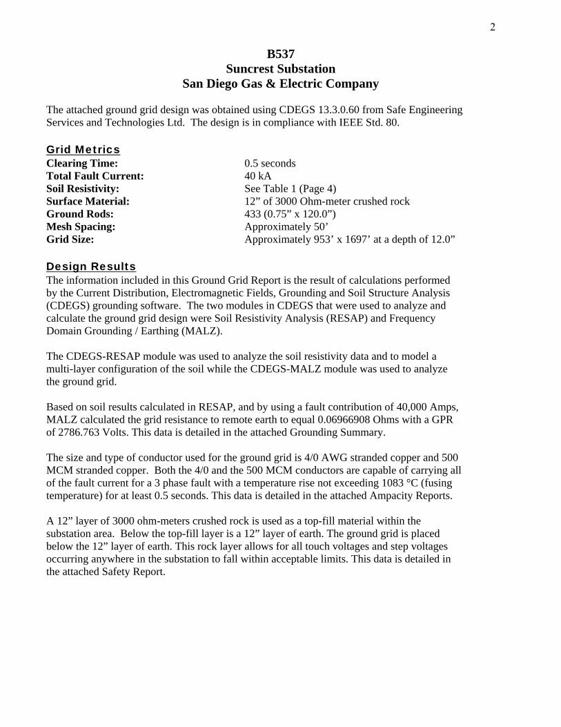
San Diego Gas & Electric Company The attached ground grid design was obtained using CDEGS 13.3.0.60 from Safe Engineering Services and Technologies Ltd. The design is in compliance with IEEE Std. 80. Grid Metrics Clearing Time: 0.5 seconds Total Fault Current: 40 kA Soil Resistivity: See Table 1 (Page 4) Surface Material: 12” of 3000 Ohm-meter crushed rock Ground Rods: 433 (0.75” x 120.0”) Mesh Spacing: Approximately 50’ Grid Size: Approximately 953’ x 1697’ at a depth of 12.0” Design Results The information included in this Ground Grid Report is the result of calculations performed by the Current Distribution, Electromagnetic Fields, Grounding and Soil Structure Analysis (CDEGS) grounding software. The two modules in CDEGS that were used to analyze and calculate the ground grid design were Soil Resistivity Analysis (RESAP) and Frequency Domain Grounding / Earthing (MALZ). The CDEGS-RESAP module was used to analyze the soil resistivity data and to model a multi-layer configuration of the soil while the CDEGS-MALZ module was used to analyze the ground grid. Based on soil results calculated in RESAP, and by using a fault contribution of 40,000 Amps, MALZ calculated the grid resistance to remote earth to equal 0.06966908 Ohms with a GPR of 2786.763 Volts. This data is detailed in the attached Grounding Summary. The size and type of conductor used for the ground grid is 4/0 AWG stranded copper and 500 MCM stranded copper. Both the 4/0 and the 500 MCM conductors are capable of carrying all of the fault current for a 3 phase fault with a temperature rise not exceeding 1083 °C (fusing temperature) for at least 0.5 seconds. This data is detailed in the attached Ampacity Reports. A 12” layer of 3000 ohm-meters crushed rock is used as a top-fill material within the substation area. Below the top-fill layer is a 12” layer of earth. The ground grid is placed below the 12” layer of earth. This rock layer allows for all touch voltages and step voltages occurring anywhere in the substation to fall within acceptable limits. This data is detailed in the attached Safety Report.
2

Section Divider
This page intentionally left blank
3

Substation Ground Grid Touch and Step Calculations The ground grid is expected to produce a maximum mesh potential rise in the center of each of the corner meshes, which is less than the acceptable touch voltage limit. Also, the expected step voltage is less than the acceptable step voltage limit. All plots attached at the end of this report confirm that all expected touch voltages within the substation are less than the maximum allowable 804.9 Volts. In addition, all step voltages within the aforementioned area are less than the maximum allowable 2751.5 Volts. Acceptable Touch Voltage Limit = 804.9 Volts (for a 0.5 second clearing time) Acceptable Step Voltage Limit = 2751.5 Volts (for a 0.5 second clearing time) Soil Resistivity Summary Three soil traverses were taken at the Suncrest Substation. After modeling each of the three traverses in RESAP, it was determined that the resistivity modeled by traverse 1 would be used to perform the calculations for the ground grid design.
*The Apparent Resistance measurements were entered into the CDEGS/RESAP module for the Traverse 1. Based on these inputs, the CDEGS/RESAP module calculated the number, the thickness, and the resistivity of the soil layers. The output for the traverse is shown on the following page.
Uniform Pin Spacing Apparent Resistance (Ohm)
D (ft.)
T1 (Northeast to Southwest)
T3 (East to West)
T4 (North to South)
0.5 27.89 61.25 15.91 1.0 18.73 25.02 12.71 1.5 15.15 21.54 0.2433 2.0 9.463 16.78 4.995 3.0 3.416 10.60 7.708 5.0 2.616 7.443 3.125 7.0 1.716 6.779 1.447 10.0 1.056 5.785 1.198 15.0 1.773 4.673 1.038 20.0 0.5155 3.983 0.9335 30.0 0.3620 3.020 0.7451 45.0 0.5406 2.092 0.6081 70.0 0.4649 1.310 0.4801 100.0 0.3228 1.185 0.4987 150.0 0.2203 1.172 0.4027 200.0 0.1824 1.285 0.3107 300.0 0.3143 450.0 0.2806 600.0 0.1716
Table 1 – Apparent Resistance Measurements
4

Section Divider
This page intentionally left blank
5
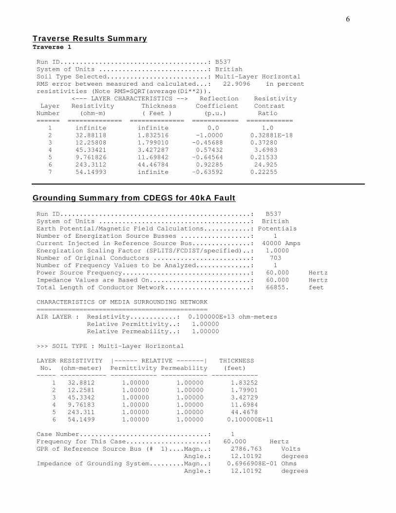
Traverse Results Summary Traverse 1 Run ID......................................: B537 System of Units ............................: British Soil Type Selected..........................: Multi-Layer Horizontal RMS error between measured and calculated...: 22.9096 in percent resistivities (Note RMS=SQRT(average(Di**2)). <--- LAYER CHARACTERISTICS --> Reflection Resistivity Layer Resistivity Thickness Coefficient Contrast Number (ohm-m) ( Feet ) (p.u.) Ratio ====== ============== ============== ============ ============ 1 infinite infinite 0.0 1.0 2 32.88118 1.832516 -1.0000 0.32881E-18 3 12.25808 1.799010 -0.45688 0.37280 4 45.33421 3.427287 0.57432 3.6983 5 9.761826 11.69842 -0.64564 0.21533 6 243.3112 44.46784 0.92285 24.925 7 54.14993 infinite -0.63592 0.22255
Grounding Summary from CDEGS for 40kA Fault
Run ID.................................................: B537 System of Units .......................................: British Earth Potential/Magnetic Field Calculations............: Potentials Number of Energization Source Busses ..................: 1 Current Injected in Reference Source Bus...............: 40000 Amps Energization Scaling Factor (SPLITS/FCDIST/specified)..: 1.0000 Number of Original Conductors .........................: 703 Number of Frequency Values to be Analyzed..............: 1 Power Source Frequency.................................: 60.000 Hertz Impedance Values are Based On..........................: 60.000 Hertz Total Length of Conductor Network......................: 66855. feet CHARACTERISTICS OF MEDIA SURROUNDING NETWORK ============================================ AIR LAYER : Resistivity............: 0.100000E+13 ohm-meters Relative Permittivity..: 1.00000 Relative Permeability..: 1.00000 >>> SOIL TYPE : Multi-Layer Horizontal LAYER RESISTIVITY |------ RELATIVE -------| THICKNESS No. (ohm-meter) Permittivity Permeability (feet) ----- ------------ ------------ ------------ ------------ 1 32.8812 1.00000 1.00000 1.83252 2 12.2581 1.00000 1.00000 1.79901 3 45.3342 1.00000 1.00000 3.42729 4 9.76183 1.00000 1.00000 11.6984 5 243.311 1.00000 1.00000 44.4678 6 54.1499 1.00000 1.00000 0.100000E+11 Case Number.................................: 1 Frequency for This Case.....................: 60.000 Hertz GPR of Reference Source Bus (# 1)....Magn..: 2786.763 Volts Angle.: 12.10192 degrees Impedance of Grounding System.........Magn..: 0.6966908E-01 Ohms Angle.: 12.10192 degrees
6

Section Divider
This page intentionally left blank
7

Safety Report from CDEGS
System Frequency............................(Hertz).: 60.000 System X/R..........................................: 20.000 Surface Layer Thickness.....................( in ).: 12.000 Number of Surface Layer Resistivities...............: 2 Starting Surface Layer Resistivity..........(ohm-m).: NONE Incremental Surface Layer Resistivity.......(ohm-m).: 3000.0 Equivalent Sub-Surface Layer Resistivity....(ohm-m).: 32.881 Body Resistance Calculation..........: IEEE Std.80-2000 Fibrillation Current Calculation.....: IEEE Std.80-2000 (50kg) Foot Resistance Calculation..........: IEEE Std.80-2000 User Defined Extra Foot Resistance: 0.0000 ohms ============================================================================== | Fault Clearing Time ( sec)| 0.250 | 0.350 | 0.500 | +----------------------------+---------------+---------------+---------------+ | Decrement Factor | 1.101 | 1.073 | 1.052 | | Fibrillation Current (amps)| 0.232 | 0.196 | 0.164 | | Body Resistance (ohms)| 1000.00 | 1000.00 | 1000.00 | ============================================================================== ========================================================================== | SURFACE | FAULT CLEARING TIME | | | LAYER |-----------------+-----------------+-----------------| | | RESIST- | 0.250 sec. | 0.350 sec. | 0.500 sec. | FOOT | | IVITY |-----------------|-----------------|-----------------| RESIST-| | (OHM-M) | STEP | TOUCH | STEP | TOUCH | STEP | TOUCH | ANCE: | | | VOLTAGE| VOLTAGE| VOLTAGE| VOLTAGE| VOLTAGE| VOLTAGE| 1 FOOT | | | (VOLTS)| (VOLTS)| (VOLTS)| (VOLTS)| (VOLTS)| (VOLTS)| (OHMS) | ========================================================================== | NONE | 254.0| 221.5| 220.3| 192.1| 188.0| 164.0| 102.8| |---------+--------+--------+--------+--------+--------+--------+--------+ | 3000.0| 3717.0| 1087.3| 3223.1| 942.8| 2751.5| 804.9| 8319.8| |---------+--------+--------+--------+--------+--------+--------+--------+ * NOTE * Listed values account for short duration asymmetric waveform
decrement factor listed at the top of each column.
8

Section Divider
This page intentionally left blank
9

Ampacity Report from CDEGS
*CDEGS Conductor Ampacity Calculation (per IEEE Standard 80)
*Ampacity report performed for the 4/0 AWG (ground grid).
Computation Results
Ampacity (RMS): 43.7344 kA, if no dc offset 41.5839 kA, with maximum dc offset
Input Data
Maximum Fault Duration: 0.5 s
Ambient Temperature: 20 °C
Maximum Allowable Temperature: 1083 °C (Fusing Temperature)
Conductor Size: 4/0 AWG Conductor Type: Copper, annealed soft drawn (100% conductivity)
Decrement Factor: 1.0517 X/R: 20 Frequency: 60 Hz
Material Constants of Conductor
Name: Copper, annealed soft drawn (100% conductivity)
Reference Temperature for Material Constants: 20.0000 °C
Thermal Coefficient of Resistivity at Reference Temperature: 0.00393 1/ °C
Fusing Temperature of Conductor: 1083.0000 °C
Resistivity of Conductor at Reference Temperature: 1.7200 μΩ⋅cm Thermal Capacity per Unit Volume: 3.4200 J/cm³ · °C
10

Section Divider
This page intentionally left blank
11
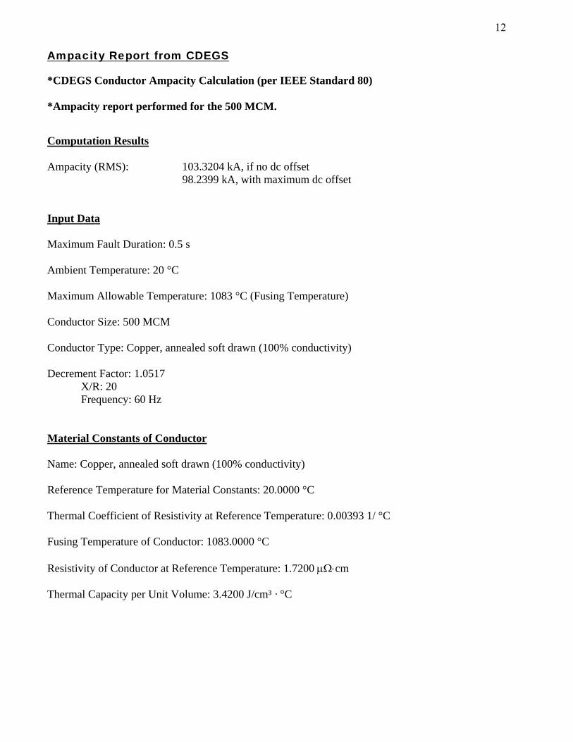
Ampacity Report from CDEGS
*CDEGS Conductor Ampacity Calculation (per IEEE Standard 80)
*Ampacity report performed for the 500 MCM.
Computation Results
Ampacity (RMS): 103.3204 kA, if no dc offset 98.2399 kA, with maximum dc offset
Input Data
Maximum Fault Duration: 0.5 s
Ambient Temperature: 20 °C
Maximum Allowable Temperature: 1083 °C (Fusing Temperature)
Conductor Size: 500 MCM Conductor Type: Copper, annealed soft drawn (100% conductivity)
Decrement Factor: 1.0517 X/R: 20 Frequency: 60 Hz
Material Constants of Conductor
Name: Copper, annealed soft drawn (100% conductivity)
Reference Temperature for Material Constants: 20.0000 °C
Thermal Coefficient of Resistivity at Reference Temperature: 0.00393 1/ °C
Fusing Temperature of Conductor: 1083.0000 °C
Resistivity of Conductor at Reference Temperature: 1.7200 μΩ⋅cm Thermal Capacity per Unit Volume: 3.4200 J/cm³ · °C
12

Section Divider
This page intentionally left blank
13

Plan View for Suncrest Substation Ground Grid
B537
GRO
UND
GRI
D P
LAN
VIE
W [
ID:B
537
@ f=
60.0
000
Hz ]
14

Section Divider
This page intentionally left blank
15
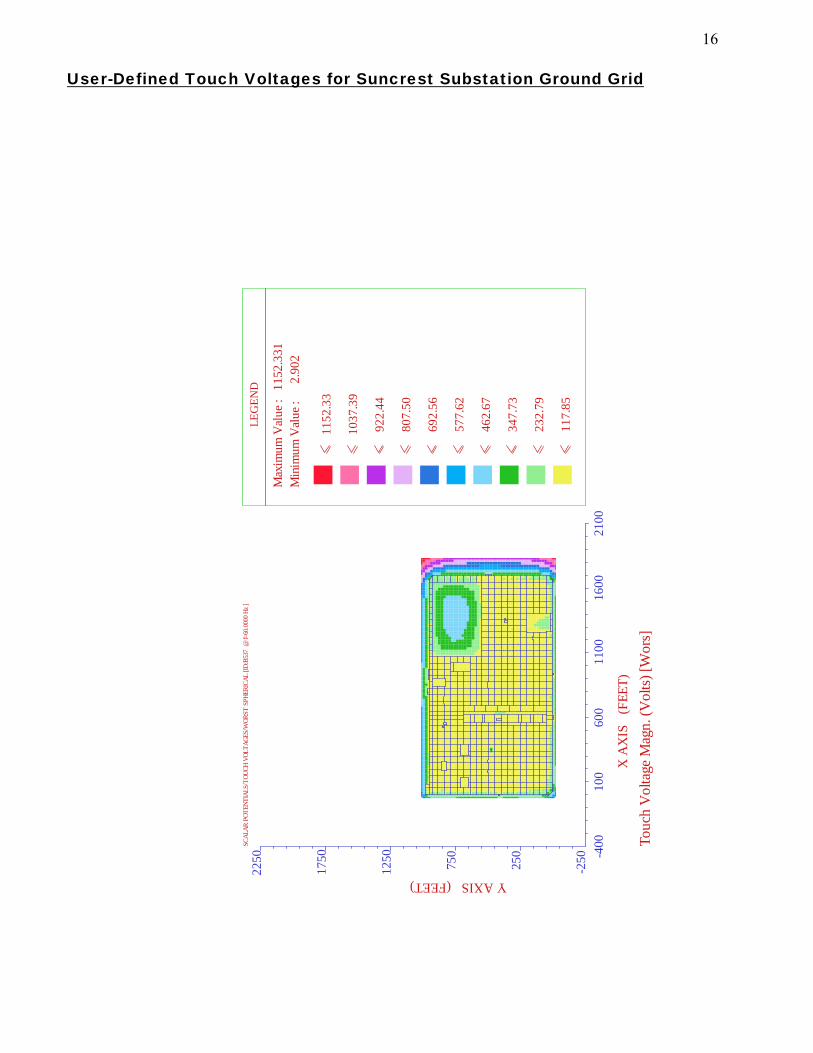
User-Defined Touch Voltages for Suncrest Substation Ground Grid
-400
100
600
1100
1600
2100
X A
XIS
(F
EET)
-250250
750
1250
1750
2250
Y AXIS (FEET)
Touc
h V
olta
ge M
agn.
(Vol
ts) [
Wor
s]
SCAL
AR P
OTEN
TIAL
S/TO
UCH
VOLT
AGES
/WOR
ST S
PHER
ICAL
[ID:
B537
@ f=
60.0
000
Hz ]
LEG
END
Max
imum
Val
ue :
115
2.33
1
M
inim
um V
alue
:
2.9
02
115
2.33
103
7.39
922
.44
807
.50
692
.56
577
.62
462
.67
347
.73
232
.79
117
.85
16

Section Divider
This page intentionally left blank
17
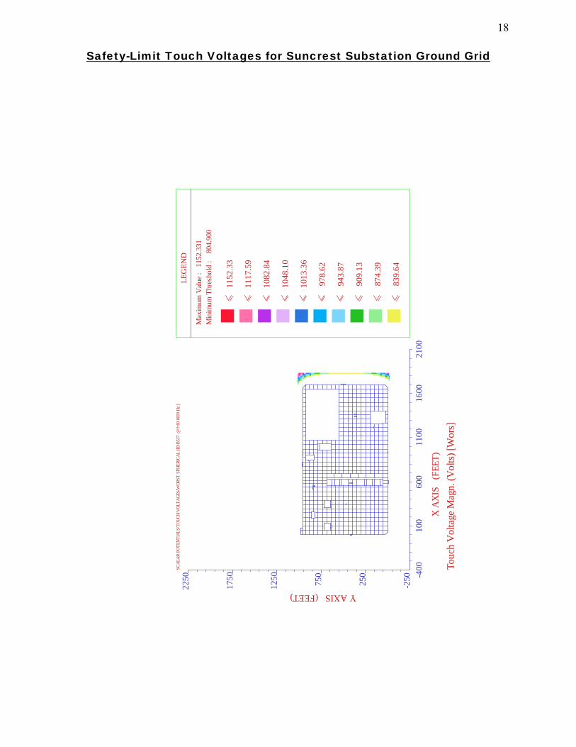
Safety-Limit Touch Voltages for Suncrest Substation Ground Grid
-400
100
600
1100
1600
2100
X A
XIS
(F
EET)
-250250
750
1250
1750
2250
Y AXIS (FEET)
Touc
h V
olta
ge M
agn.
(Vol
ts) [
Wor
s]
SCAL
AR P
OTEN
TIAL
S/TO
UCH
VOLT
AGES
/WOR
ST S
PHER
ICAL
[ID:
B537
@ f=
60.0
000
Hz ]
LEG
END
Max
imum
Valu
e :
115
2.33
1
M
inim
um T
hres
hold
:
804.
900
115
2.33
111
7.59
108
2.84
104
8.10
101
3.36
978
.62
943
.87
909
.13
874
.39
839
.64
18

Section Divider
This page intentionally left blank
19
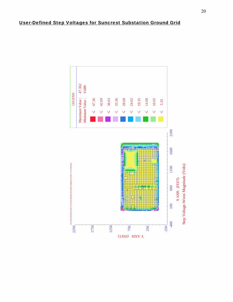
User-Defined Step Voltages for Suncrest Substation Ground Grid
-400
100
600
1100
1600
2100
X AX
IS
(FEE
T)
-250250
750
1250
1750
2250
Y AXIS (FEET)
Step
Vol
tage
-Wor
st M
agni
tude
(Vol
ts)
SCAL
AR P
OTEN
TIAL
S/STE
P VO
LTAG
ES (S
PHER
ICAL
)/WOR
ST SP
HERI
CAL
[ID:B
537
@ f=
60.00
00 H
z ]
LEG
END
Max
imum
Val
ue :
4
7.36
2
M
inim
um V
alue
:
0.6
80
47
.36
42
.69
38
.03
33
.36
28
.69
24
.02
19
.35
14
.68
10
.02
5
.35
20

Section Divider
This page intentionally left blank
21
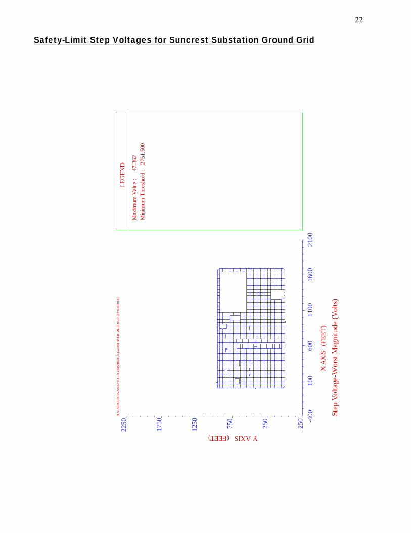
Safety-Limit Step Voltages for Suncrest Substation Ground Grid
-400
100
600
1100
1600
2100
X AX
IS
(FEE
T)
-250250
750
1250
1750
2250
Y AXIS (FEET)
Step
Vol
tage
-Wor
st M
agni
tude
(Vol
ts)
SCAL
AR P
OTEN
TIAL
S/STE
P VO
LTAG
ES (S
PHER
ICAL
)/WOR
ST SP
HERI
CAL
[ID:B
537
@ f=
60.00
00 H
z ]
LEG
END
Max
imum
Valu
e :
47
.362
M
inim
um T
hres
hold
: 2
751.
500
22
Section Divider
This page intentionally left blank
23

Scalar Potential Profile for Suncrest Substation Ground Grid
-400
100
600
1100
1600
2100
X A
XIS
(F
EET)
-250250
750
1250
1750
2250
Y AXIS (FEET)
Pote
ntia
l Pro
file
Mag
nitu
de (V
olts)
SCAL
AR P
OTE
NTI
ALS/
SCAL
AR P
OTE
NTI
ALS
[ID
:B53
7 @
f=60
.000
0 Hz
] L
EGEN
D
Max
imum
Val
ue :
269
0.29
5
M
inim
um V
alue
: 1
352.
121
269
0.29
255
6.48
242
2.66
228
8.84
215
5.03
202
1.21
188
7.39
175
3.57
161
9.76
148
5.94
24