I lllllll llll llill lllll lllll lllll lllll llll llll ... Heport t.\D==-A244 009 I lllllll llll...
38
' '!.: .' Final Heport t.\D==-A244 009 I lllllll llll llill lllll lllll lllll lllll llll llll USATHAMA U.S. Army Toxic and Hazardous Materials Agency ECONOMIC EVALUATION OF PROPELLANT REUSE/RECOVERY TECHNOLOGY (TASK ORDER N0.10) December 1988 Contract No. DAAK11-85-D-0008 Prepared by: Arthur D. Little, Inc. Acorn Park Cambridge, Massachusetts 02140-2390 Prepared for: U.S. Army Toxic and Hazardous Materials Agency Process Development Branch 'Aberdeen Proving Ground, MD 21010-5401 DISTRIBUTION UNLIMITED 000554
Transcript of I lllllll llll llill lllll lllll lllll lllll llll llll ... Heport t.\D==-A244 009 I lllllll llll...
' '!.: .'
Final Heport
t.\D==-A244 009 I lllllll llll llill lllll lllll lllll lllll llll llll
USATHAMA U.S. Army Toxic and Hazardous Materials Agency
ECONOMIC EVALUATION OF PROPELLANT REUSE/RECOVERY
TECHNOLOGY (TASK ORDER N0.10)
December 1988 Contract No. DAAK11-85-D-0008
Prepared by:
Arthur D. Little, Inc. Acorn Park
Cambridge, Massachusetts 02140-2390
Prepared for:
U.S. Army Toxic and Hazardous Materials Agency
Process Development Branch 'Aberdeen Proving Ground, MD 21010-5401
DISTRIBUTION UNLIMITED
000554

..
The views, opinions, and/or findings contained in this report should not be construed as an official Department of the Army position, policy, or decision, unless so designated by other documentation.
The use of trade names in this report does not constitute an official endorsement or approval of the use of such commercial products. This report may not be cited for purposes of advertisement.
II
I
I I I
I I I I I
I I I I
000555

Economic Evaluation of Propellant Reuse/Recovery Technology
(Task Order Number 10)
Final Report
A.A. Balasco Program Manager
R.F. Machacek - Task Leader R.C. Bowen C.A. Jake (RAAP) L.L. Smith (RAAP) Principal Investigators
Distribution Unlimited
Jt. Arthur D. Little, Inc.
Final Report to United States Army Toxic and Hazardous Materials Agency December 1988
- - .. ---1,7'. •• • :'{.
•Y9 t ' .,. .t
· .11.•,. • 'J·1 c:'l
; 4 ~,·.~:.4• al~, ....
I.· ' t .J•..J, ~ U•,
... ~ : ' .,.... ~ .
<..' ~ ..
,t\-\ .
Contract No. DAAK11-85-D-0008 Reference 54150
91-18801 I llllll lllll lllll lllll lllll lllll lllll llll 111:
000556

List of Tables
List of Figures
EXECUTIVE SUMMARY
1.0 INTRODUCTION
1.1 Background 1.2 Objective 1.3 Scope of Work
TABLE OF CONTENTS
2.0 WASTE PROPELLANT RECYCLING OPTIONS
2.1 Introduction 2.2 Resolvation Processes 2.3 Solvent Extraction Processes
3.0 ECONOMIC ANALYSIS
3.1 Introduction 3.2 Resolvation Process Cost Estimates 3.3 Discussion About Solvent Extraction Costs
4.0 CONCLUSIONS AND RECOMMENDATIONS
5.0 REFERENCES
APPENDIX A
'lrtlur D Little
i
ii
iii
ES-1
1-1
1-1 1-2 1-2
2-1
2-1 2-1 2-5
3-1
3-1 3-1 3-10
4-1
5-1
A-1
000557
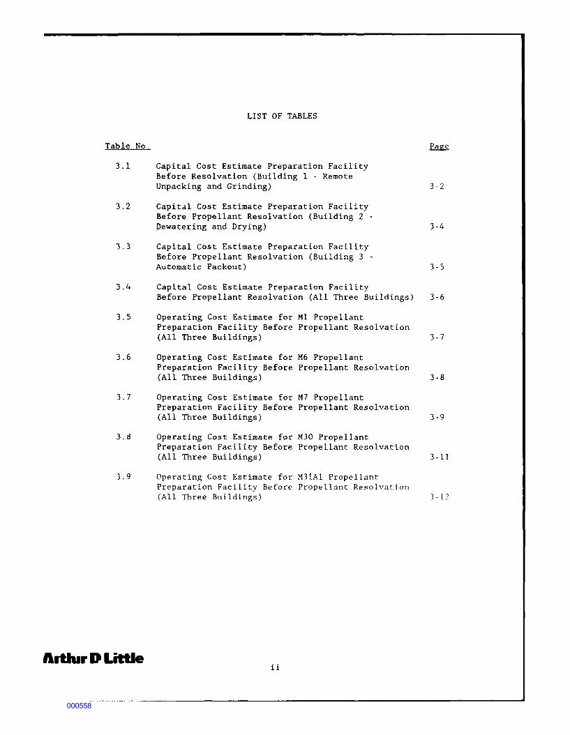
Table No.
3.1
3.2
3.3
3.4
3.5
3.6
3.7
3.8
3.9
llltlur D Little
LIST OF TABLES
Capital Cost Estimate Preparation Facility Before Resolvation (Building 1 - Remote Unpacking and Grinding)
Capital Cost Estimate Preparation Facility Before Propellant Resolvation (Building 2 -Dewatering and Drying)
Capital Cost Estimate Preparation Facility Before Propellant Resolvation (Building 3 -Automatic Packout)
Capital Cost Estimate Preparation Facility Before Propellant Resolvation (All Three Buildings)
Operating Cost Estimate for Ml Propellant Preparation Facility Before Propellant Resolvation (All Three Buildings)
Operating Cost Estimate for M6 Propellant Preparation Facility Before Propellant Resolvation (All Three Buildings)
Operating Cost Estimate for M7 Propellant Preparation Facility Before Propellant Resolvation (All Three Buildings)
Operating Cost Estimate for M30 Propellant Preparation Facility Before Propellant Resolvation (All Three Buildings)
Operating Cost Estimate for M31Al Propellant Preparation Facility Before Propellant Resolvatinn (All Three Buildings)
ii
3-2
3-4
3-5
3-6
3-7
3-8
3-9
3-11
3 - 12
000558

LIST OF FIGURES
Figure No. Page
2.1 Schematic Flow Diagram for Propellant Grinding (Building 1) 2-2
2.2 Schematic Flow Diagram for Propellant Grinding (Building 2) 2-3
2.3 Schematic Flow Diagram for Propellant Grinding (Building 3) 2-4
Artlur D Little iii
000559

EXECUTIVE SUMMARY
This report presents an economic evaluation of two reclamation/reuse options for solvent-based obsolete and unserviceable propellants: (1) resolvation/reuse of propellants; and (2) reclamation/reuse of selected propellant ingredients via solvent extraction. Both of these options were r~cently investigated to determine their technical feasibility under a previous task [Task Order No. 7 under U.S. Army Toxic and Hazardous Materials Agency (USATHAMA) Contract No. DAAKll-85-0-0008] and detailed in a report (USATHAMA Reference No. AMXTH-TE-CR-88026, August 1988) entitled "Propellant Reuse/Recovery Technology" prepared by Arthur D. Little, Inc.
According to the Environmental Conference Proceedings of the "Hazardous Waste Minimization Interactive Workshop" sponsored by the U.S. Army Material Command (AMC) in November 1987, the demilitarization inventory contained 158,000 metric tons of obsolete conventional propellants in 1987 with a projected growth to 249,000 metric tons by 1993. All of the propellants in this demilitarization inventory are potential candidates for reclamation/reuse.
The incentive for considering reuse options center both on the cost savings for: (a) not having to incinerate the obsolete propellants: and (b) avoiding the purchasing of new raw materials for new propellants. The two reclamation/reuse options we considered were:
• resolvation of the obsolete propell "nts to produce the equivalent single-, double-, or triple-based new propellants; and
• solvent extraction of the obsolete propellants to separate and recover individual ingredients in the propellants.
Of the two options, the resolvation of obsolete propellants provides the greatest savings by reclaiming and, therefore, taking credit for the entire mix ot ingredients in the original propellant formulation. In contrast, solvent extraction reclaims only selected ingredients. Consequently, one should probnbly consider employing solvent extraction only on chemically off-specification propellants. a much smaller category of propellants than those in the demilitarization inventory. As a result. it was decided to concentrate on the laq~<"1·.
demilitarization inventory and focus our economic evaluation on reclaiming/reusing five representative propellants via resolvatio11:
• Ml propellant (single-based):
• M6 propellant (single-based);
• M7 propellant (double-based stick);
• M30 propellant (triple-based); and
• M31Al propellant (triple-based).
Artlur D Little ES-1
000560

Another reason for not devtloping capital and operating cost estimates for the solvent extraction reclamation/reuse processes is that they are in an earlier stage of development than the resolvation process. In addition, the solvent used in the bench-scale solvent extraction tests, methylene chloride, has been classified as both carcinogenic and mutantigenic to human health. Consequently, one should exercise great caution before considering the use of this solvent. As an alternative, one might investigate the use of a safer solvent such as supercritical carbon dioxide.
Capital and annual operating costs were developed for a plant to grind the obsolete propellants under water, then dry the propellant, and finally pack the propellant prior to resolvation. This plant, with a design capacity to process 3 million pounds per year (1,500 tons per year) of obsolete propellant, would have a total installed equipment cost of $5.8 million. The annual net operating savings from this plant range from a low of $3.0 million from processing only single-based Ml propellant to a high of $7.4 million processing only triple-based M31Al propellant. The payback periods on invested capital range from a high of 1.9 years for Ml propellant to a low of 0.8 year for M31Al.
If one were to estimate the capital investment for the solvent extraction processes, one would have to start (as with the resolvation process) with a $5.8 million capital cost for a plant to grind the unserviceable propellants. One has, in addition, the capital investments for the solvent extraction processes since it can not use any existing facilities. Consequently, the higher investments for the solvent extraction process would appear to limit its applicability to only chemically off-specification propellants.
ArtlurDLittle ES-2
000561

1 . 0 INTRODUCTION
1.1 BACKGROUND
The Department of the Army (DA), as the single service manager of the Department of Defense (DOD) ammunition, is responsible for the disposal of obsolete and unserviceable propellants. In recent years, disposal of propellant munitions has become increasingly complicated due to heightened environmental awareness and resulting legislation. Until the early 1970's, munitions were disposed of by open sea dumping. However, the Marine Protection, Research and Sanctuaries Act of 1972 was passed" ... to prevent or strictly limit the dumping into ocean waters of any material that would adversely affect human health, welfare or amenities, or the marine environment, ecological systems, or economic potentialities." (1) In particular, the act restricted ocean disposal of DOD materiel, and as a result, open field burning and detonation became the dominant methods of destroying obsolete or unserviceable propellant munitions. However, even these practices are now subject to increasing restrictions from environmental regulations.
The regulations promulgated under the Resource Conservation and Recovery Act (RCRA), as amended in 1984, prohibit open burning of hazardous waste, " ... except for the open burning and detonation of waste explosives. Waste explosives include waste which has the potential to detonate and bulk military propellants which cannot be disposed of through other modes of treatment." (2) While the current Federal regulations exempt military materiel from such controls and allow disposal of these items by open field burning and detonation, the future may bring increased environmental restriction in the form of new Federal regulations.
It must be noted that state and local governments are allowed to impose restriction on hazardous waste disposal that are more stringent than the Federal regulations. Such future restrictions could pctentially affect open denotation at many U.S. Army installations. Some states or localities may refrain from issuing environmental permits for open burning and open detonation; this has already been the case at two Arm\· installations: Hawthorne Army Ammunition Plant (Hawthorne, Nevada) and Lexington Blue Grass Army Depot (Lexington, Kentucky). (3) The future method of destruction of propellants will be controlled incineration.
The intent of RCRA, however, is to promote a reduction in hazardous waste through increased recovery of useful resources, while ensuring that any necessary hazardous waste disposal operations are environmentally sound. Thus, the recovery of obsolete and unserviceable propellants is consistent with the intent of RCRA, and may be an attractive alternative to thermal treatment of these items. The Army has adopted this philosophy and has given top priority to recovery and reuse of obsolete and unserviceable propellants. (4,5)
ArtJur D Little 1-1
000562

1. 2 OBJECTIVE
The objective of this task was to evaluate the economic feasibility of reclaiming and reusing propellants from obsolete and unserviceable munitions. This involved developing both capital and operating costs for the reprocessing (reclamation/reuse) of several types of propellants. The net credit for reprocessing the propellant(s) included the credit for the savings on new raw mciterials and the savings from avoiding costs of incinerating the obsolete propellant(s) minus the operating costs of grinding the obsolete propellant(s).
1.3 SCOPE OF WORK
Under Contract No. DAAKll-85-0-0008, with the U.S. Army Toxic and Hazardous Materials Agency (USATHAMA), Process Development Branch, Arthur D. Little, Inc. was issued Task Order No. 10 entitled "Computerization and Application of a Standard Cost Evaluation Method." We based our work on the bench-scale studies carried out at Radford Army Ammunition Plant (RAAP) on grinding, drying and packing obsolete propellants and either resolvating them or recovering the raw materials by solvent extraction. The report entitled "Propellant Reuse/Recovery Technology" (6) presents the results of these tests. We also used the costs of equipment for processing developed by Radford Army Ammunition Plant personnel (7). With this information, we have developed budgetary (± 40%) estimates of the total capital investment for the grinding of the propellants and the operating costs of the processing of the propellants.
'1rtlur D Little 1-2
000563

2.0 WASTE PROPELLANT RECYCLING OPTIONS
2.1 INTRODUCTION
There are two major approaches to the reclamation/reuse of obsolete and unserviceable propellant munitions:
• resolvation of the obsolete propellants to produce the equivalent single-, double-, or triple-based new propellants; and
• solvent extraction of the obsolete propellants to separate and recover individual ingredients.
The following two sections describe each process and indicates the major processing steps. Section 2.2 describes the resolvation processes for the five propellants investigated and the plant to reprocess these propellants. The resolvation of any of the five propellants evaluated involve grinding it under water, drying it, and packing it into drums. One may produce new propellant by resolvating the ground propellant in an existing propellant production line. Section 2.3 describes both the solvent extraction processes for the same five propellants and the limitations of these processes.
2.2 RESOLVATION PROCESSES
The resolvation process will use existing production lines for the extrusion of the new propellants. The only additional step necessary for this reclamation operation is the grinding of the obsolete propellant. For obvious safety considerations, the propellant must be ground under water, then dried and finally repacked into drums for storage. From storage, the drums of ground propellant would be sent to the production lines.
The grinding operation is the same for all the different types of propellants and can be carried out in the same grinding equipment. The production rate is also the same for all types of propellants. namely 500 pounds per hour. In actu~l operation, however, one would have to carefully clean the grindi~6· drying and packing equipment and replace the grinding water befor~ processing a new type of propellant. It might be desirable, thP~efore, to have dedicated grinding lines for an~ of the largest quantj -Y propellants.
Figures 2.1, 2.2 and 2.3 present schematic flow diagrams of the eq~ipment necessary for the grinding operations. To limit the quantit~ of propellant in a single building, we have placed the operations into three separate buildings. In the first building, shown schematically in Figure 2.1, remote unpacking of drums of obsolete propellant, checking for any stray metal, and then grinding of the propellant as a water slurry in a knife grinder is carried out. In Figure 2.2 for the second building, screening of the ground propellant slurry on a Sweco screen, drying of it in a Wolverine drier, and placing of the dried
lrtlurDLittle 2-1
000564

FIGURE 2.1
SCHEMATIC FLOW DIAGRAM FOR PROPELLANT GRINDING
<BUILDING 1)
Water Spray
Recycle Water from Sweco®
Separator
Remote Unpacking
Conveyor
Metal Detector
Grinder
Surge Tank
Source: Hercules Aerospace Co. (RAAP)
Arthll' D Little 2-2
000565

FIGURE 2.2
SCHEMATIC FLOW DIAGRAM FOR PROPELLANT GRINDING
(BUILDING 21
Sweco® Separator
____ _. Recycle \"later to Grinder
Propellant
Wolverine® Drier
Di.·mr Hopper
Air Conveyor
Source: Hercules Aerospace Co. (RAAP)
Artlur D LittJe 2-3
000566

FIGURE 2.3
SCHEMATIC FLOW DIAGRAM FOR PROPELLANT GRINDING
<BUil DING 31
Cyclone St)parator
Feed Hopper
Metal Detector
Weigh Loader and Lid Sealer
Palletizer
Drummed Ground
Propellant to Existing
Production
Source: Hercules Aerospace Co. (RAAP)
Artlur D Little 2-4
000567

propellant into an air conveyor to be sent to the third building takes place. In Figure 2.3 for the third building, the recovering of the propellant in a cyclone separator, checking for metal again, and weighing and loading of drums of ground propellant is carried out. ~e
have based the estimates of capital costs shown in Section 3.2 on the installed costs of the equipment shown in Figures 2.1, 2.2 and 2.3.
2.3 SOLVENT EXTRACTION PROCESSES
Any of the solvent extraction processes will require grinding of the unserviceable propellant in equipment identical to that used to grind the propellant for resolvation. Thus the equipment shown in the previously cited Figures 2.1, 2.2 and 2.3 will also be required for the solvent extraction processes. In addition, to this grinding equipment, solvent extraction equipment is also required. The type and complexit:; of the solvent extraction equipment will vary depending on whether one extracts single-, double-, or triple-based propellants. The more complex propellants such as the double- or triple-based types will require more processing steps to separate the individual ingredients before their reuse than the single-based type. A separate extraction plant will have to be built and dedicated to each type of propellant.
Since the bench-scale tests employed a solvent, methylene chloride, that should not be used for worker safety reasons, further bench-scale tests need to be performed. These tests need to be performed before one develops any designs or prepares any associated cost estimates. The only general comments one can make is that any solvent extraction process by its nature will be more complex and costly than resolvation. The more costly nature of any solvent extraction processes will limit their applicability to propellants that can not be processed by resolvation, i.e., chemically off-specification propellants.
Artlur D Little 2-5
000568

3.0 ECONOMIC ANALYSIS
3.1 INTRODUCTION
This economic evaluation of reclamation/reuse options for obsolete and unserviceable propellants addresses two fundamental issues:
• USATHAMA currently has no comprehensive capital and operating cost data base for the reuse/recovery of obsolete and unserviceable propellants; and
• The economic attractiveness of the concept of reusing propellants must be established to support management decisions regarding future expenditures for research and development of these technologies.
To assist in addressing these issues, this report provides budgetary capital and operating costs for the resolvation of five propellants discussed in Section 3.2. In Section 3.3, the report discusses the economics of solvent extraction processes, to the extent practicable, and the need for further research studies to help define these processes before additional costing can be performed.
3.2 RESOLVATION PROCESS COST ESTIMATES
As was discussed in Section 2.2, the only new equipment for the resolvation of propellants w0uld be for the actual grinding of the obsolete propellant. After the grinding, one could use the ground obsolete propellant as feed to an existing production line. The equipment for grinding is the same for all five propellants, and thus one estimate for capital investment is valid for each type of propellant. We have divided the grinding operations into three separate buildings to minimize the total amount of propellant (for safety considerations) in any one building.
The equipment, which would be housed in the first building, includes a trolley conveyor, a barrel dumper, a vibratory conveyor, a metal detector, a slurry knife grinder and a ground propellant slurry tank. The equipment is sized to handle 1,000 pounds per hour of propellant for flexibility while the typical throughput will average 500 pounds per hour. The equipment costs are budgetary in nature and have an uncertainty of plus or minus 40%. As is shown in Table 3.1, the purchased equipment in the first building totals $405 thousand. Addin~
in as a percentage of the equipment cost; installation labor at 25%. piping at 30%, electrical at 20%, and spare parts at 2%, the total direct cost amounts to $775 thousand. Adding in the engineering and supervision, overhead and fee, and the contingency as indicated in Table 3.1, the total capital investment amounts to $1.0 million.
The equipment for the second building includes a Sweco® separator, a vibratory conveyor, a Wolverine® drier and an air conveyor that total $1.35 million. The costly items of equipment are the Wolverine® drier
ArtlurDLittJe ~l
000569

Table 3.1
Capital Cost Estimate for Preparation Facility Before Propellant Resolvation
(Building 1 - Remote Unpacking and Grinding)
Equipment Item Quantity
Trolley Conveyor System 1 Dump Hopper, Stainless Steel 1 Vibratory Feeder 1 Vibratory Conveyor 1 Metal Detector 1 Grinder Feed Hopper 1 Grinder 1 Slurry Tank 1 Slurry Pump and Piping 1
• SUBTOTAL EQUIPMENT COST
Installation Labor Piping Electrical Instrumentation Spare Parts
0 TOTAL DIRECT COST
Engineering and Supervision @ 8% Contractor's Overhead and Fee @ 15%
• TOTAL DIRECT AND INDIRECT COST
Contingency @ 10%
• TOTAL CAPITAL INVESTMENT
Source: Hercules Aerospace Company (RAAP) and Arthur D. Little, Inc.
Artlur D Little 3-2
$
$
$
$
Total Cost
($ , 000)
35 5
25 25
5 5
265 25 ] 5
405
100 120
60 80 10
775
60 115
950
() -.)
1,045
000570

and the custom fabricated air conveyor at over $600 thousand each. Adding in all the factored costs as ~e did in the previous cited Table 3.1, we see in Table 3.2 a total capital investment of $3.5 million for the second building.
The equipment for the third building includes a cyclone separator, a metal detector, a weigh loader and a lid sealer, a roller conveyor, a palletizer and another roller conveyor at a total cost of $475 thousand. Adding the factored installation costs, one sees in Table 3.3 a total capital investment of $1.2 million for the third building. To find the total capital investment for all three buildings, Table 3.4 presents a total capital investment of $5.8 million.
One of the reasons for the large uncertainty in the capital investments is that one needs a total systems hazards analysis to ensure that the proposed facilities provide adequate safety to personnel and property. One must assess the potential hazards and ensure that all equipment and subsequent operations meet acceptable safety criteria provided in DARCOMR-385-3 and Supplement 1, "Hazards Analysis for Facilities, Equipment and Process Development." Since many of the operations proposed in the facilities already exist at Radford AAP, one may use previous system safety study findings where applicable. Where systems design and operation or modifications preclude use of existing hazards assessments, then one must identify potential hazards and assess them quantitatively to eliminate or control potential hazards to an acceptable level.
If one looks at the operating costs for grinding the propellants and at the savings resulting from recycling the obsolete propellants, one can estimate the net operating credit. For the single-based propellant Ml. there is a net operating cost (Table 3.5) for grinding of $1.52 million per year. One requires an additional expenditure of $0.6 million for replacement solvents and ingredients for the new propellant. Offsetting these costs are a credit of $3.75 million for avoided new raw materials and a credit of $1.38 million for avoided incineration of the obsolete propellant resulting in a net operating credit of $3.0 million per year.
In Table 3.6, for the single-based propellant M6. a slightly higher ne~ credit for recovery of $3.9 million per year is realized. This slightly higher net credit is caused solely by the larger credit for the avoided raw materials for the M6 propellant compared to the ~l propellant.
For the double-based propellant, M7, one has an even higher net credit for recovery of $7.0 million per year. The larger credit, shown in Table 3.7, is due to a number of factors. The replacement ingredients cost less; there is a credit for avoided labor for nitroglycerin blending; and a larger credit for avoiding more costly raw materials. A trend can be realized that the more complex the propellant, the greater the net credit for its resolvation into a new propellant.
Artlur D Little 3-3
000571

Table 3 .2
Capital Cost Estimate for Preparation Facility Before Propellant Resolvation
(Building 2 - Dewatering and Drying)
Equipment Item Quantity
Swecc® Separator 1 Feed Hopper 1 Vibratory Conveyor 1 Wolverine® Drier with Steam Heater 1 Dump Hopper 1 Air Conveyor 1
• SUBTOTAL EQUIPMENT COST
Installation Labor Piping Electrical Instrumentation Spare Parts
o TOTAL DIRECT COST
Engineering and Supervision @ 8% Contractor.'s Overhead and Fee @ 15%
• TOTAL DIRECT AND INDIRECT COST
Contingency G 10%
o TOTAL CAPITAL INVESTMENT
Source: Hercules Aerospace Company (RAAP) and Arthur D. Little, Inc.
Artlur D Little 3-4
$
$
$
$
Total Cost
($ '000)
15 5
20 660
5 645
1,350
340 405 200 270
30
2,595
210 390
3,195
320
3,515
000572

Table 3.3
Capital Cost Estimate for Preparation Facility Before Propellant Resolvation
(Building 3 - Automatic Packout)
Equipment Item Quantity
Cyclone Separator with Bag Filter 1 Feed Hopper 1 Metal Detector 1 Weigh loader and Lid Sealer 1 Powered Roller Conveyor 1 Palletizer with Telescoping Roller
Conveyor and Pallet Stacker 1 Powered Roller Conveyor System 1
• SUBTOTAL EQUIPMENT COST
Installation Labor Costs Piping Electrical Instrumentation Spare Parts
• TOTAL DIRECT COST
Engineering and Supervision @ 8% Contractor's Overhead and FPe @ 15%
e TOTAL DIRECT AND INDIRECT COST
Contingency @ 10%
o TOTAL CAPITAL INVESTMENT
Source: Hercules Aerospace Company (RAAP) and Arthur D. Little, Inc.
Artlur D Little 3-5
$
$
$
$
Total Cost
($ '000)
10 5
10 260
15
75 100
475
120 145
70 95 10
915
75 140
1.130
110
1,240
000573
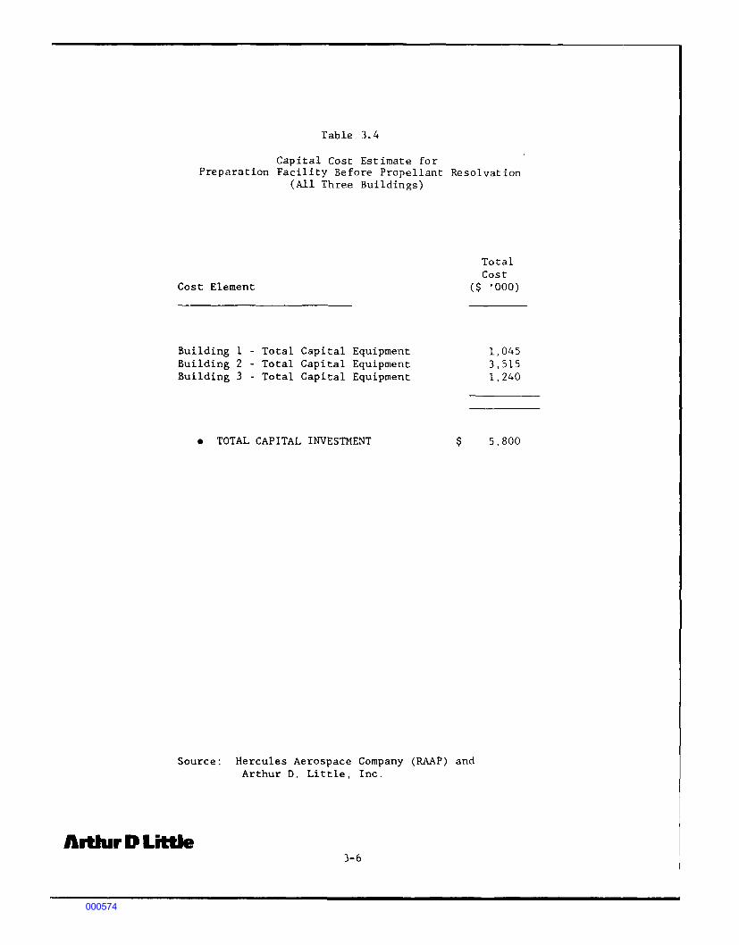
Table 3. 4
Capital Cost Estimate for Preparation Facility Before Propellant Resolvation
(All Three Buildings)
Total Cost
Cost Element ( $ , 000)
Building 1 - Total Capital Equipment Building 2 - Total Capital Equipment Building 3 - Total Capital Equipment
• TOTAL CAPITAL INVESTMENT $
Source: Hercules Aerospace Company (RAAP) and Arthur D. Little, Inc.
Artlur D Little 3-6
1,045 3,515 1,240
5,800
000574

Table 3. 5
Operating Cost Estimate for Ml Propellant Preparation Facility Before Propellant Resolvation
(All Three Buildings)
Basis: 24 Hour Long Stream Day 250 Stream Days Per Year 12,000 Pounds Processed Per Stream Day
Operating Item
Labor Fringe and Holidays
Utilities
Unit Units Required
Manhours 33,900 55% of Labor
Maintenance 4% of Total (Labor and Materials) Capital Investment
General and Adminstrative 72% of Labor and Overhead Maintenance
• NET TOTAL OPERATING COST
Replacement Propellent Ingredients
Credit for Avoiding New Raw Materials
Credit for Avoiding Incineration
Million Lbs
Million Lbs
3.00
3.00
• ~ET CREDIT FOR RECOVERY OF PROPELLENT
Source: Hercules Aerospace Company (RAAP) and Arthur D. Little, Inc.
Artlur D Little 3-7
Cost per Unit
$10.80
($1,250,000)
($460,000)
Total Cost
($'000)
365 200
150
230
575
$1,520
600
3,750)
1,380)
($3,010)
000575
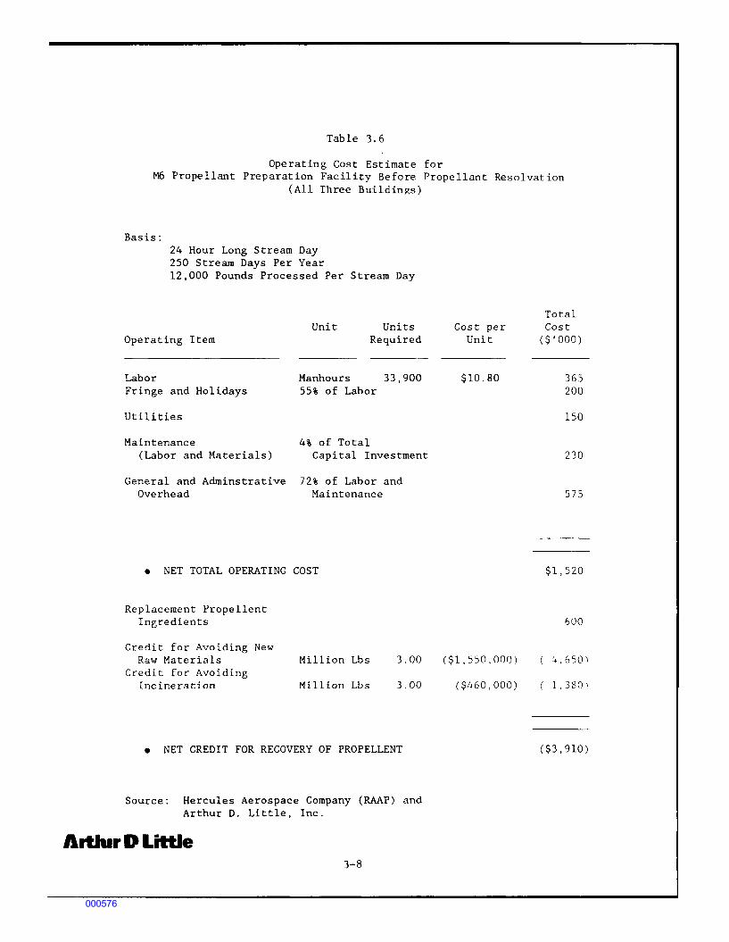
Table 3. 6
Operating Cost Estimate for M6 Propellant Preparation Facility Before Propellant Resolvation
(All Three Buildings)
Basis: 24 Hour Long Stream Day 250 Stream Days Per Year 12,000 Pounds Processed Per Stream Day
Operating Item
Labor Fringe and Holidays
Utilities
Unit Units Required
Manhours 33,900 55% of Labor
Maintenance 4% of Total (Labor and Materials) Capital Investment
General and Adminstrative 72% of Labor and Overhead Maintenance
• NET TOTAL OPERATING COST
Replacement Propellent Ingredients
Credit for Avoiding New Raw Materials
Credit for Avoiding Incineration
Million Lbs
Million Lbs
3.00
3.00
• NET CREDIT FOR RECOVERY OF PROPELLENT
Source: Hercules Aerospace Company (RAAP) and Arthur D. Little, Inc.
Artlur D Little 3-8
Cost per Unit
$10.80
($1,550,000)
($460.000)
Total Cost
($'000)
365 200
150
230
575
$1,520
600
'i.650)
1. 380)
($3,910)
000576

Table 3. 7
Operating Cost Estimate for M7 Propellant Preparation Facility Before Propellant Resolvation
(All Three Buildings)
Basis: 24 Hour Long Stream Day 250 Stream Days Per Year 12,000 Pounds Processed Per Stream Day
Unit Operating Item
Units Required
Labor Manhours 33,900 Fringe and Holidays 55% of Labor
Utilities
Maintenance 4% of Total (Labor and Materials) Capital Investment
General and Adminstrative 72% of Labor and Overhead Maintenance
o NET TOTAL OPERATING COST
Replacement Propellent Tne,redi2nts
Credit for Avoiding Labor in Nitroglycerine Blending
Credit for Avoiding New Raw Materials Million Lbs
Credit for Avoiding Incineration Million Lbs
3.00
3.00
o NET CREDIT FOR RECOVERY OF PROPELLENT
Source: Hercules Aerospace Company (RAAP) and Arthur D. Little, Inc.
Artlur D Little 3-9
Cost per Unit
$10.80
($2,220,000)
($460,000)
Total Cost
($'000)
365 200
150
230
575
$1,520
120
( 57111
1,380)
($6,970)
000577

In Table 3.8, a net credit of $6.4 million per year is realized for resolvation of the triple-based propellant M30. In Table 3.9, it is evident that the largest net savings is for the triple-based propellant M31Al, a savings of $7.4 million per year. The triple-based propellants require less grinding than the other propellants and have lower operating costs for grinding. They also have the largest credits for avoiding very expensive raw materials. Resolvating the more complex propellants offers the greatest cost savings, but all propellants provide an attractive net operating credit.
The payback periods for the capital investment range from the longest of 1.9 years for the single-based Ml propellant to the shortest of 0.8 years for the triple-based M31Al propellant. All of the payback periods are highly attractive with the shorter paybacks for the more complex double- and triple-based propellants.
3.3 DISCUSSION ABOUT SOLVENT EXTRACTION COSTS
With any solvent extraction process, the unserviceable propellant will have to be ground in the same equipment as for the resolvation process discussed in Section 3.2. Thus, all of the capital costs associated with the grinding equipment would apply to any solvent extraction process. Also, the operating costs for grinding would apply as shown in the net total operating cost line in the previously cited Tables 3.5 to 3.9. However, there would be additional costs for the solvent extraction processes to cecover the individual ingredients in the propellants. All these additional capital and operating costs for the solvent extraction processes would decrease the overall attractiveness of solvent extraction as compared to resolvation.
Since we do not have well-defined processes or solvents identified. it is not possible to develop total capital or operating costs for the solvent extraction options at this time. It is obvious, however, that for the more complex propellants, one would require a more complicated process for separation of the ingredients which would result in more expensive equipment. In all cases, solvent extraction options would b~ less attractive than the corresponrilng resolvation option. Thus. chemically off-specification propellants would be the primary candidat0 for solvent extraction since these propellants can not be recovered b~ the less expensive resolvation option.
ArtlurDLiH:Je 3-10
000578

Table 3. 8
Operating Cost Estimate for M30 Propellant Preparation Facility Be fore Propellant Re sol vat ion
(All Three Buildings)
Basis: 24 Hour Long Stream Day 250 Stream Days Per Year 12,000 Pounds Processed Per Stream Day
Operating Item
Labor Fringe and Holidays
Utilities
Maintenance (Labor and Materials)
Unit Units Required
Manhours 25,200 55% of Labor
4% of Total Capital Investment
General and Adminstrative 72% of Labor and Overhead Maintenance
o NET TOTAL OPERATING COST
Replacement Propellent Ingredients
Credit for Avoiding New Raw Materials
Credit for Avoiding Incineration
Million Lbs
Million Lbs
3.00
3.00
o NET CREDIT FOR RECOVERY OF PROPELLENT
Source: Hercules Aerospace Company (RAAP) and Arthur D. Little, Inc.
Artlur D Little 3-11
Cost per Unit
$10.80
($2,210,000)
($'~60,000)
Total Cost
($'000)
270 150
150
230
470
$1. 270
390
l, 38()\
($6,350)
000579

l I I I I I
I
I I
Table 3.9
Operating Cost Estimate for M31Al Propellant Preparation Facility Before Propellant Resolvation
(All Three Buildings)
Basis: 24 Hour Long Stream Day 250 Stream Days Per Year 12,000 Pounds Processed Per Stream Day
Operating Item
Labor Fringe and Holidays
Utilities
Unit Units Required
Manhours 1 ~, L•J1•
55% of l.~hor
Maintenance 4% of Tota~ (Labor and Materials) Capital Investment
General and Adminstrative 72% of Labor and Overhead Maintenance
• NET TOTAL OPERATING COST
Replacement Propellent Ingredients
Credit for Avoiding New Raw Materials
Credit for Avoiding Incineration
Million Lbs
Mill ion Lbs
3.00
3.00
o NET CREDIT FOR RECOVERY OF PROPELLENT
Source: Hercules Aerospace Company (RAAP) and Arthur D. Little, Inc.
Artlur D Little 3-12
Cost per Unit
$10.80
($2 .1~so. oom
($460,000)
Total Cost
($'000)
195 llO
150
230
385
$1,070
300
( 7,3501
l,38Cll
($7,360)
000580

4.0 CONCLUSIONS AND RECOMMENDATIONS
The major conclusion of this report on reclamation/reuse of obsolete propellants is that resolvation is a very economically attractive option for reuse of obsolete propellants. The capital investment for the grinding of the obsolere propellant is $5.8 million, and one can use existing production li11es for the resolvation without any further capital investment. The capital investment produces a net operating credit ranging form $3.0 million to $7.5 million per year and attractive payback periods ranging from the longest of 1.9 years to shortest of 0.8 year.
We recommend that the U.S. Army proceed with a detailed design and costing study of the grinding process in preparation for the potential construction and operation of a facility at Radford AAP. We suggest Radford as the site of this facility, because it has the only operating production lines that could conveniently resolvate the ground obsolete propellant.
The major conclusion on the solvent extraction processes is that they require further bench-scale testing with a less hazardous solvent such as supercritical carbon dioxide. Without these tests, one can not develop meaningful budgetary capital investment cost estimates. However, it is clear that more capital equipment will be required for solvent extraction than that for resolvation; consequently, the capital costs for solvent extraction will be higher than for resolvation. This will most likely limit the use of any solvent extraction process to recovery of only chemically off-specification propellants.
Consequently, we recommend that the U.S. Army consider funding further bench-scale testing of solvent extraction processes for chemically off-specification propellants, but only after carefully evaluating the need for such, depending on both the actual and anticipated generation of such off-specification propellants.
ArtlurDLittle 4-1
000581

l I
5.0 REFERENCES
1. "Marine Protection, Research and Sanctuaries Act of 1972," enacted by P.L. 92-532, October 23, 1972, 86 Stat. 1052; 33 U.S.C. 1401 et. ~; Amended by P.L. 93-254, March 22, 1974; P.L. 93-472, October 26, 1974; P.L. 94-62, July 25, 1975; P.L. 94-326, June 30, 1976; P.L. 95-153, November 4, 1977; P.L. 96-332, August 29, 1980; P.L. 96-381, October 6, 1980; P.L. 96-470, October 19, 1980; P.L. 96-572, December 22, 1980; P.L. 97-16, June 23, 1981; P.L. 97-109, December 26, 1981; P.L. 97-375, December 21, 1982; P.L. 97-424, January 6, 1983; P.L. 98-498, October 19, 1984.
2. "Resource Conservation and Recovery Act, Part 265, Interim Status Standards for Owners and Operators of Hazardous Waste Treatment, Storage and Disposal Faciliti.es, Subpart P, Thermal Treatment, Section 265.382, Open Burning, Waste Explosive," 40 CFR 265, 45 FR 33232, May 19, 1980, Effective November 19, 1980; Revised as shown in 40 CFR, July 1, 1982; Amended by 47 FR 30447, July 13, 1982; 47 FR 32349, July 26, 1982, Effective January 26, 1983; 47 FR 44938, October 12, 1982; 48 FR 2511, January 19, 1983; 48 FR 3981, January 28, 1983; 48 FR 14153, April l, 1983; 48 FR 30115, June 30, 1983; 48 FR 52720, November 22, 1983; 49 FR 46095, November 21, 1984; 50 FR 661, January 4, 1985, Effective July 5, 1985; 50 FR 1999, January 14, 1985, Effective July 15, 1985; 50 FR 4513, January 31, 1985; 50 FR 16048, April 23, 1985, Effective October 23, 1985; 50 FR 18374, April 30, 1985, Effective June 14, 1985; 50 FR 28742, July 15, 1985.
3. Zaugg, M. M., Ammunition Equipment Directorate, Tooele Army Depot, Tooele, Utah, Personal Communication with Arthur D. Little, Inc., Cambridge, Massaschusetts, January 15, 1986.
4. "Hazardous Waste Management," Personal Communication, Headquarters. U.S. Army Materiel Development and Readiness Command, DRClS-S letter, 30 November 1979.
5. ''Efficient Use of Resources," Personal Communication. Headquarters. U.S. Army Materiel Development and Readiness Command, DRCCP letter. 4 June 1981.
6. Propellant Reuse/Recovery Technology (Task Order No. 7) CSATHA.'~\
Report No. AMXTH-TE-CR-88026, prepared by Arthur D. Little, Inc. under Contract No. DAAKll-85-0-0008, August 1988.
7. "Cost Estimating Information on a Conceptual Propellent Resolvation Preparation Facility," Radford Army Ammunition Plant Memorandum by J. F. Cross, September 14, 1988.
Artlur D Little 5-1
000582

APPENDIX A
A description of and the associated costs for the equipment necessary for the grinding operation of a conceptual propellant resolvation facility are presented in this Appendix. This information was provided by Hercules Aerospace Co. (RAAP).
~l
000583

ltdl'I
A
'!" N
8
c
Table I. Potential e<1Jipnent for conceptual propellant resolvation preparation facility
I U~" J VI U
Building I - Ren-ote Unpacking and Grinding (Building Size -5092 ft2; Process flow rate - 1100 lb propellant/h)
fguipnent
Trolley Conveyor System
DlJlll Hopper
Vibratory Feeder
Current value, 1a,b
36,560
1,875
25,845
Description
System contains the fol lowing for explosionproof sen ice:
a. Drive unit assenbly - 1500 lb capacity for speeds of 2 to 10 ft per min CO!Jlllete with:
I . Worm reducer 2. link belt 3. Motor - 3 hp 4. Chain drive 5. Drive guard 6. Coup I ing(s) 7. Drive sprocket
b. Screw take-up 90° traction wheels (2) and turns (2)
c. Stainless steel track and chain d. Anti-backup and anti-runaway devices e. Trolleys (39) with attactvnents f. Electric re1T0te speed and indicator controls
Hopper and appendages are 304 stainless steel that ~ets Hercules Incorporated weld specifications for explosive service. Size is 42-in. dia. inlet and 20-in. dia. exit. Equipnent was custom fabricated for process.
Model No. f P-2480S: 1/4 in. 316 stainless steel with I-hp rrotor. Feeder is a vibrating type of conveyor designed to regulate the flow of material from a hopper. Trough is constructe1 in a single section with the drive firmly attached. Entire machine is suspended from or supported by low frequency isolation springs. Size is 12-ft long by 10-in. high to acc~date dUIT{> hopper.
Manufacturer
Material Handling Systems Inc., Atlanta, GA Now: FMC Corp., Material
Handling Systems Div. Colmar, PA
American Sheet Metal, Inc. Doraville, GA Now: General Metals, Inc.
Electromate Corp. Jacksonvi I le, FL
Carrier Vibrating fquipnent, Inc., Louisville, KY Now: Rexnord, Inc., Conveying
fquipnent Operation Milwaukee, WI
000584

> I
w
Item
D
E
f
G
H
Page 2 of 8
Table I. Ccon1)
Building I - Rerrote Unpacking and Grinding (Building Size -5092 f1l; Process flow rate - I 100 lb propellan1/h)
fguirrent
Vibratory Conveyor
Metal Detector
Grinder feed hopper
Grinder
S furry ~ank
Current value, ia,b
25,170
3,975
1,875
267,410
25,200
Description
Model No. SSD-24BOF: 1/4 in. 316 stainless steel - 33 ft 2 in. with 2-hp !T()tor. The complete conveyor is 40-ft long and 2-ft wide having a 1° slope decline capable of producing a dynamic reaction with a horizontal CCJrll>Onent of ± 2204 lb and a vertical CCXll>Qnent of ± 1276 lb. CCXflXlnent parts are 1wo gates, drive, belt guard, and fiberglass flat leaf.
Hodel is a standard series detector for tra1r4> ~tal with an electrom3gnetic conveyor-type rectangular coil (8-1/2 in. wide by 6-in. high coi I opening) for feed rate of 15 to 600 ft per minute.
Hopper and appendages are 316 stainless steel that ~ets Hercules Incorporated weld specifications for explosive service. Size is 23-3/4 in. dia. inlet and 21-in. dia. exit. Equip:rent was custom fabricated for process.
Knife grinder wi1h cutting charrber having rotating and stationary knives with sized screen in bottom discharge section for particle size reduction. Grinding of propellants is accomplished underwater. Maximum propellant and water feed rates are 1100 lb/hand 3300 lb/h, respectively. All equip:rent is rated for explosion-proof service. Model No. 14-(Sf stainless steel Hog. Motor requir~nt is 150-hp.
Tank is 304 stainless steel that ~ets Hercules Incorporated weld specifications for explosive service. Tank capacity is 1700 gal. Tank is 8-ft high by 6-ft dia. Tank has agitator driven by 15-hp motor to keep propellant and water as a slurry.
Manufacturer
Carrier Vibrating Equip:rent, Inc., Louisvi lie, KY Now: Rexnord, Inc., Conveying
fquip:rent Operation Milwaukee, WI
ITT Industrial Automation Systems Now: ITT Power Systems Corp.
Ga I ion, OH
.American Sheet Metal, Inc. Doraville, GA Now: General Metals, Inc.
flectrom3te Corp. Jacksonville, fl
Mitts & Merrill, Inc. Saginaw, Ml Now: Mitts & Merri I I Products
Div., Carthage Machine Co. Carthage, NY
.American Sheet Metal, Inc. Doravi I le, GA Now: General Metals, Inc.
flectrom3te Corp. Jack\>onville, Fl
000585

- ._. '-' - ___. ~ ~ - - Page } of 8
Table I. (cont)
Building I - RemJte Unpacking and Grinding (Building Size -5092 ft2 process flow rate - 1100 lb propellant/h)
Item
~ ~
£guiprent
Slurry Pllll> and piping
Current va I ue, $a,b
16, I 55c
Description
Model No. 2-VRG-200: capable of >BO grin for a total head of 76 ft. 2-in. horizontal p~ with II-in. irrveller for various speeds and and 20-hp rrntor for explosion-proof service. rrrn - 1600; frame - 215-T; Type - TEFC; voltage - 230/460/360. Piping requirement is -250-ft 304 stainless steel schedule 40 3-in. dia. pipe.
Manufacturer
The Galigher Co. Jersey City, NJ Now: BG A International
Salt lake City, UT
000586

-
> I ~
- - - - - - - - Page 4 of 8
Table I. (cont)
Building 2 - Dewatering and Drying (Building Size -2560 ft2; Process flow rate - 1000 lb propellant/h)
Item Eguipnent
J Swecoe separatord
I( Feed hopper
L Vibratory conveyor
M Wolverine8 dryer with steam heater
N D~ hopper
Current value, ia,b
n,615
4,440C
21,260
659, 595e
3,7ooc
Description
Swecoe Vibro-fnergy separator Hodel No. A-10-8 containing 48-in. ~creen (150 mesh, 0.0041-in. wire dia., 0.0026-in. wire opening), leveling separator, and l'l()tor, ground, and spout connections, uses 2-1/2 hp explosion-proof l'l()tor.
Custom-fabricated isometric design of aluminum; 3 ft 6 in. by -6 in. opening, horizontal retraction 234°, vertical retraction 90°; welded according to Hercules Incorporated specifications.
Custom-fabricated of aluminum; 2 ft 6 in. by 4 ft 9 in. welded according to Hercules I ncorpora·ied specifications.
165 ft2 jet zone dryer consisting of 4 l'l()dules: first m:x1ule is 2 ~ 15 ft for r81'1()ving unbound l'l()isture from propellant that could be present; last 3 m:x1ules are 1-1/2 x 30 ft for drying; propellant bed depth is I to 2 in. Each l'l()dule contains 2 fans (2400 cfm max), supply air unit is balanced with the fans. Seven cyclone participators are present throughout 165 ft2 train. Construction is 304 stainless steel meeting Hercules Incorporated explosive service and die checked welds. Temperature requirement is 140°f for drying nitroglycerin (NG) containing propellants (40\ NG). Heat is serviced by steam.
Custom-fabricated of standard design having 30 in. opening of alllninum welded according to Hercules Incorporated specifications.
Manufacturer
Sweco, Inc. Los Angeles, CA Now: Emerson Electric Co./
Sweco Inc. Los Angeles, CA
Wolverine Corporation Merrimac, MA
Wolverine Corporation Merrimac, HA
Wolverine Corpordtion Herr i mac , HA
Wolverine Corporation Merrimac, HA
000587
-
> I
O'
Item
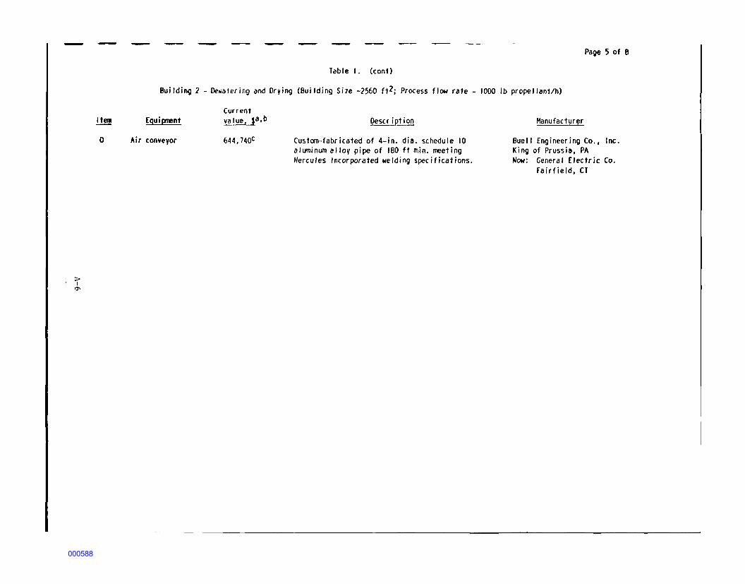
0
Page 5 of 8
Table I. (con1)
Building 2 - Dewafering and Drying (Building Size ~2560 f12; Process flow rate - 1000 lb propellant/h)
fguiirrent
Air conveyor
Current value, ia,b
644, 74oc
Oescr i pt ion
Custom-fabricated of 4-in. dia. schedule 10 aluminum allov pipe of 180 ft min. meeting Hercules Incorporated welding specifications.
Manufacturer
Buel I fngineering Co., Inc. King of Prussia, PA Now: General f lectric Co.
Fairfield, CT
000588
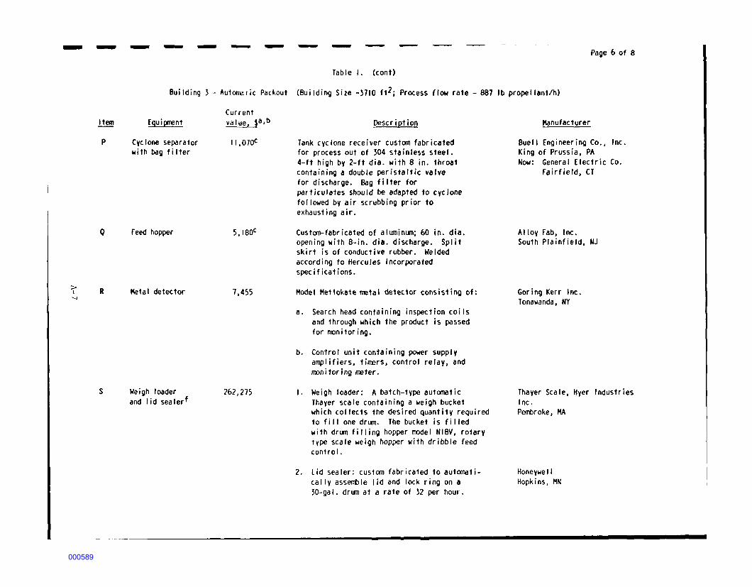
__ .._. ______ _ Page 6 of 8
Table I. (cont)
Building 3 - Autom:1 ic Packout (Building Size -3710 ft2; Process flow rate - 887 lb propel lant/h)
> I
--.J
Item
p
Q
R
s
fgui(J!lent
Cyclone separator with bag filter
feed hopper
Metal detector
Weigh loader and I id sea lerf
Current value, ia,b
11,070c
5, IBQC
7,455
262,275
Description
Tank cyclone receiver custom fabricated for process out of 304 stainless steel. 4-ft high by 2-ft dia. with 8 in. throat containing a double peristaltic valve for discharge. Bag filter for particulates should be adapted to cyclone followed by air scrubbing prior to exhausting air.
Custom-fabricated of aluminlJll; 60 in. dia. opening with 8-in. dia. discharge. Split skirt is of conductive rubber. Welded according to Hercules Incorporated specifications.
Hodel Metlokate metal detector consisting of:
a. Search head containing inspection coils and through which the product is passed for m:rn i tori ng.
b. Control unit containing power supply amplifiers, timers, control relay, and m:>nitoring rreter.
I. Weigh loader: A batch-type automatic Thayer scale containing a weigh bucket which collects the desired quantity required to fill one drln'!. The bucket is filled with drum filling hopper m:>del Nl8V, rotary 1ype scale weigh hopper with dribble feed control.
2. Lid sealer: custom fabricated to automatically assent>le lid and lock ring on a 30-gal. drllll at a rate of 32 per hour.
Hanuf acturer
Buell fngineering Co., Inc. King of Prussia, PA Now: General Electric Co.
Fairfield, CT
Alloy Fab, Inc. South Plainfield, NJ
Goring Kerr Inc. Tonawanda, NY
Thayer Scale, Hyer Industries Inc. Pent>roke, MA
Honeywel I Hopkins, MN
000589
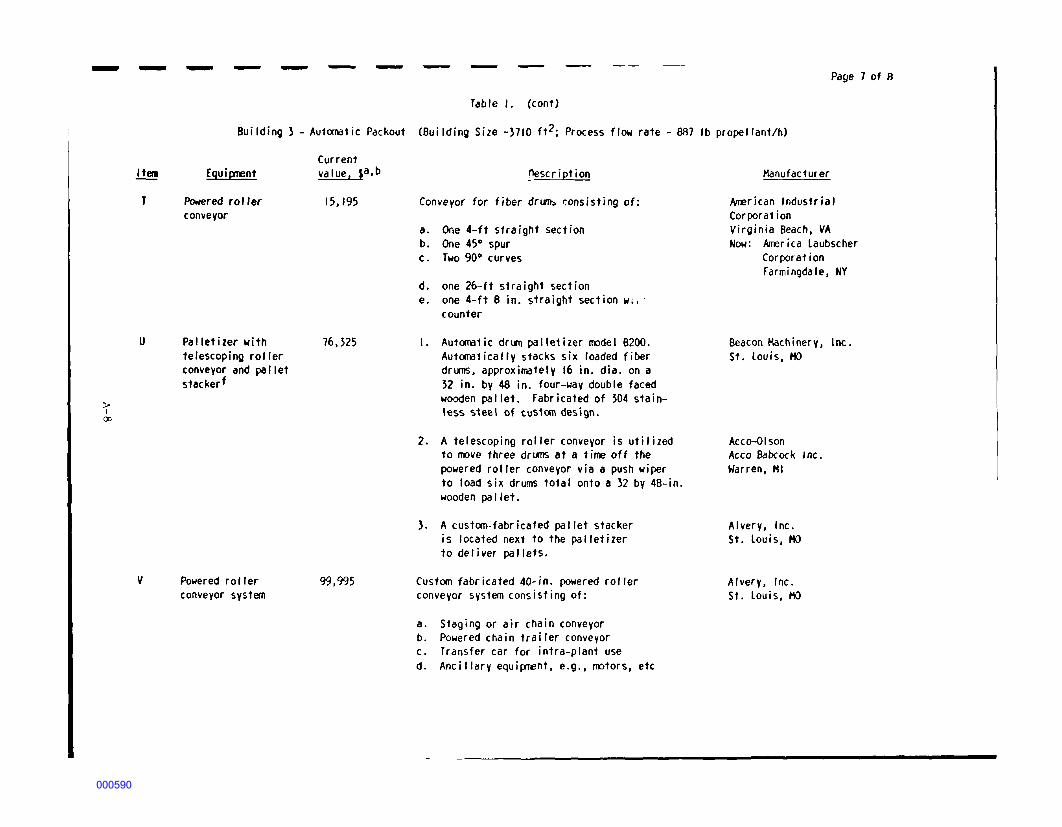
- - - - - - - - - Page 7 of R
Table I. (cont}
Building 3 - Automatic Packout CBui lding Size -3710 ft2; Process flow rate - 887 lb propellant/h)
> I
00
Item
T
u
v
fguipnent
Powered roller conveyor
Pal letizer with telescoping roller conveyor and pa I let stackerf
Powered roller conveyor system
Current value, $a,b
15, 195
76,325
99,995
pescription
Conveyor for fiber drUIJb ~onsisting of:
a. One 4-ft straight section b. One 45° spur c. Two 90° curves
d. one 26-ft straight section e. one 4-ft 8 in. straight section w1, •
counter
I. Aut~1ic dru:n palle1izer m::idel B200. Aut~fically stacks six loaded fiber drlJTIS, approximately 16 in. dia. on a 32 in. by 48 in. four-way double faced wooden pallet. Fabricated of 304 stainless s1eel of cus1om design.
2. A telescoping roller conveyor is utilized to rrove three drllTtS at a time off the powered roller conveyor via a push wiper to load six drums total onto a 32 by 48-in. wooden pallet.
3. A custom-fabricated pallet stacker is located next to the palletizer to deliver pallets.
Custom fabricated 40-in. powered roller conveyor system consisting of:
a. Staging or air chain conveyor b. Powered chain trailer conveyor c. Transfer car for intra-plant use d. Ancillary equii;rnent, e.g., ITJ'.)tors, etc
Manufacturer
~rican Industrial Corporation Virginia Beach, VA Now: Alrerica Laubscher
Corporation Farmingdale, NY
Beacon Machinery, Inc. St. Louis, HO
Acco-Olson Acco Babcock Inc. Warren, HI
Alvery, Inc. St. Louis, HO
Alvery, Inc. St. Louis, HO
000590

------ - - - -- - Page 8 of 8
;p. I
'°
a
b
c
d
e
f
g
Calculated us•ng Cf plant cost indexes, "fconomic Indicators•" Chemical Engineering, Vol. 95, No. 10, p. 9, Julv 18, 1988.
If project 1ni3terial is purchased at RAAP, an additional 20.831 overhead cost is required per the 88 Change I Proposal.
Calculated using Cf plant cost indexes, "fconomic Indicators," Chemical fngireering, Vol. 95, No. 10, p. 9, July 18, 1988 and Peters, Max S. and Turrrerhaus, Klaus 0., Plant Design and Economics for Chemical Engineers, 3rd fd., McGraw-Hill Book C°"l)any, New York, NY e 1980.
Another Hercules Incorporated facility uses a Baker-Perkins pusher-type centrifuge for dewatering.
Based on drying double-base flake propellant in a Wolverinee dryer at another Hercules Incorporated facility.
lid sealer is not in continuous operation during packout; current method is manual operation.
Palletizer has a pallet magazine which is loaded manually with a capacity for about 4 h of operation.
000591