I! ll - DeRamp.comderamp.com/downloads/floppy_drives/teac/TEAC FD-55GFR.pdfThe FDD is equipped with...
52
1-1. GENERAL This SPECIFICATION provides a description for the TEAC FD-55GFR, 5.25", high/nor:nal densities, double sided mini flexible disk drive (hereinafter referred to as the FDD) . Table 100 shows the ou::line of the FDD. Model name ! FD-SSGFR-440 I FD-55GFR-540 TEAC P/N 19307273-40 19307274-40 I 19307275-40 Safety stanC.21rd on label - UL I u· .., & CSA Unformatted data capacity I! l. 6M/l. OM bytes Track density I! 96tpi Head load mechanism ll Not equipped (CSS) Front bezel shape I\ TEAC s;:andard Front lever shape Ji TE.ll.C standard Bezel & lever color Ji Black LED indicator color II Red Pop-up mechanism \i Not equipped Shield cover Ii Not equipped Frame ground terminal 11 Fas ton 187 tab " Input . ' S-1.gnc.....i.. tezminator Ii 330)1 ± 5% on IC socke;: Cus-:omer selectable .straps II DO 'V D3, uo, Ul, IU, ir RY, DC2, LG, _.., ;o..,, L.t., I/II/IS I FG Refer to item 1-11. Strap setting _ ... shipment I! Dl, Ul, DC2, -II I FG G.'" Other optional functions II Not equipped & mechanism (Table 100) Specification outline - 101 -
Transcript of I! ll - DeRamp.comderamp.com/downloads/floppy_drives/teac/TEAC FD-55GFR.pdfThe FDD is equipped with...

1-1. GENERAL
This SPECIFICATION provides a description for the TEAC FD-55GFR, 5.25",
high/nor:nal densities, double sided mini flexible disk drive (hereinafter
referred to as the FDD) . Table 100 shows the ou::line of the FDD.
Model name ! FD-55GFR-3~0 FD-SSGFR-440 I FD-55GFR-540
TEAC P/N ~ 19307273-40 19307274-40 I 19307275-40
Safety stanC.21rd on label ~ - UL I u· .., & CSA
Unformatted data capacity I! l. 6M/l. OM bytes
Track density I! 96tpi
Head load mechanism ll Not equipped (CSS)
Front bezel shape I\ TEAC s;:andard
Front lever shape Ji TE.ll.C standard
Bezel & lever color Ji Black
LED indicator color II Red
Pop-up mechanism \i Not equipped
Shield cover Ii Not equipped
Frame ground terminal 11 Fas ton 187 tab "
Input . ' S-1.gnc.....i.. tezminator Ii 330)1 ± 5% on IC socke;:
Cus-:omer selectable .straps II DO 'V D3, uo, Ul, IU, ir RY, DC2, LG, _..,
;o..,, L.t.,
I/II/IS I FG Refer to item 1-11.
Strap setting _ ...
shipment I! Dl, Ul, DC2, -II I FG G.'"
Other optional functions
II Not equipped
& mechanism
(Table 100) Specification outline
- 101 -

The FDD is equipped with an input signal for switching high/normal
densities on the terminal No,2 of the signal interface connector.
When the high density mode is designated, the FDD operates like
conventional 8 inch, double sided double density FDD in data capacity
and data transfer rate with high density mini flexible disk.
When the normal density is designated, the FDD operates like conventional
5.25", 96tpi, double sided FDD. It can read and write the data of 5.25",
96tpi, single/double sided flexible disks, and it can also read the data
of conventional 5.25", 48tpi, single/double sided disks.
For the normal density mode, two disk rotational speeds are offered for
selection using internal switching strap (short bar). One is 300rpm
which is 1:urrently used in 5.25" FDDs and the other is 360rpm which is
the same speed as in high density mode.(also the same as in 8" FDDs).
Table 101 shows the summary of the FDD performance.
Speed mode Density mode Unformatted Disk rotation Data transfer data capacity speed rate/sec
Dual speed High 1.6M ·bytes 360rptn SOOK bits
Normal l.OM ·bytes 300rprn 250K bits
Single speed High 1.6M bytes .360rptn SOOK bits
Normal l.OM bytes 360rprn 300K bits
(Table 101)-Performance summary
1-2.-DISK
130mm (5.25 inch) ·soft sectored high density flexible disks (for high
.density mode) or l30rrun (5.25 inch) soft sectored normal density flexible
disks (for normal density .mode) which are mutually agreed between the
customer and ~-C~
Since it is impossible for the FDD to identify which type of disks is
installed, it is required for the host controller to provide some
control such as detection of sector identifier or previous designation of
the density.
- 10:: -
) ./
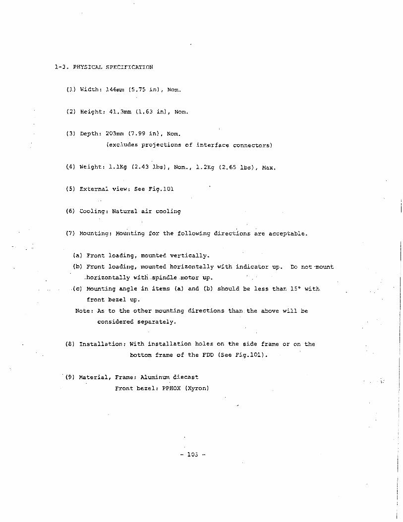
l-3. PHYSICAL SPECIFICATION
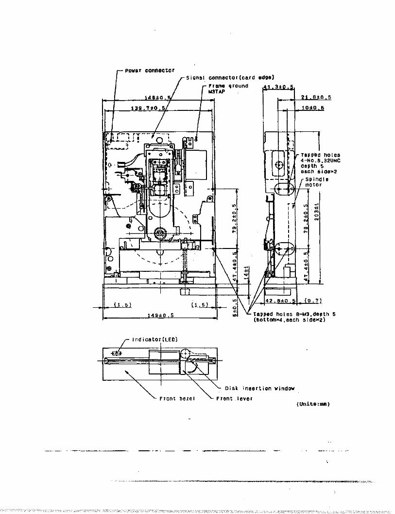
(l) Width: l46mm (5.75 in), Norn.
(2) Height: 41.3mm (l.63 in), Norn.
(3) Depth: 203mm (7.99 in), Norn.
(excludes projections of interface connectors)
(.4) Weight: l.lKg (2.43 lbs), Norn., l.2Kg (2.65 lbs), Max.
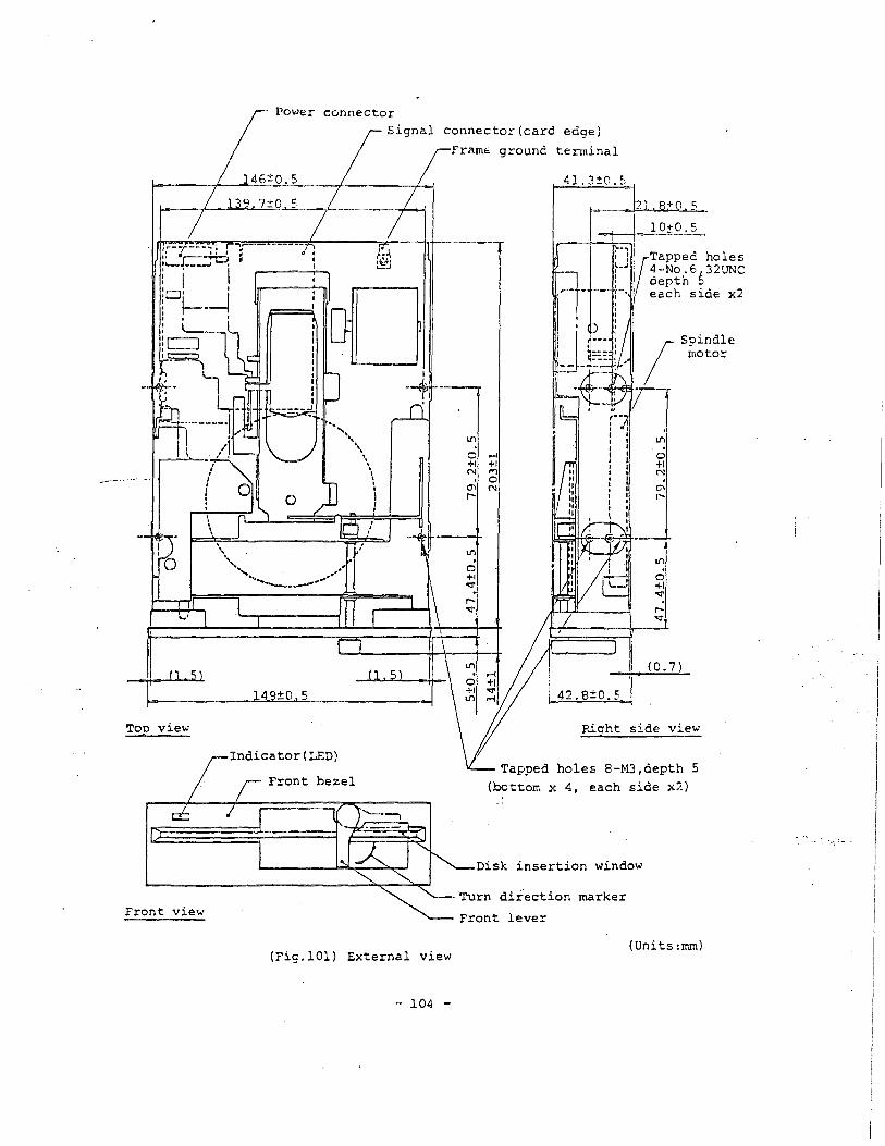
(5) External view: See Fig.101
(6) Cooling: Natural air cooling
(7) Mounting: Mounting for the following directions are acceptable.
(a) Front loading, mounted vertically.
(b) Front loading, mounted horizontally with indicator up. Do not-mount
.horizontally witn ---Spindle._motor up~
.(c) Mounting angle in items (a) and (b) should be less than 15° with
front bezel up.
Note: As to the-other-mounting directions than the above will be
considered separately.
(8) Installation: With installation holes on the side frame or on the
bottom frame of the FDD (See Fig.101).
· (9) Material, Frame: Aluminum diecast
Front bezel: PPHOX (Xyron)
- 103 -
-----·.
0
....
Top view
Front view
\ \
Power connector
Signal connector(card edge)
146±0.5
39.7±0 5
49±0.5
Indicator(LED)
Front bezel
(Fig.101) External view
- 104 -
framE ground terminal
Lil
0 +I N
Cf\
"'
~
+I ,.., 0 N
41.3±0.5
2' 8±0 5
• I I 10±0.5 .----.,,.--...,
/ "l (Tapped holes ~-"' 4-No.6 32UNC i depth 5 ,~ each side x2
! Spindle
motor
~-ef...,---.-
Lil . 0 +1 N
C)'\
"'
Lil
0 +I "</'
"' _____ __::i
(0.7)
42. 8±0. s.
P.icrht side view
Tapped holes 8-M3,depth 5 (bottom x 4, each side x2)
Disk insertion window
marker
Front lever
(Units:mm)

1-4. REQUIRED POWER
The following specifications are applicable at the power connector of
the FDD.
(l) OC+l2V
(a) Voltage tolerance
Read/write operation: Less than ±5%
Others Less than ±10%
(b) Allowable ripple voltage: Less than 200rnVp-p (including noise)
(c) Operating current consumption
Typical average: 0.22A
(using a disk of typical running torque)
Maximum average: Less than 0.54A
(using a disk of maximum running torque)
Peak:. Les<; than .LOA c400msec I Max. at spindle motor start)
(d) Waiting current consumption (spi~dle 1I1otor off)
Typical: 0.03A
Maximum: -0.04A.
(2) OC+5V
(a) Voltage tolerance: ±5%
(b) Allowable ripple voltage: Less than lOOrnVp-p (including noise)
(c) Operating current consumption
Typical average: 0.30A
Maximum average: Less than 0.38A
Peak: Less than 0.46A
(d) Waiting current consumption
Typical: 0.23A
Maximum: Less than 0.2BA
(3) Power consumption
- 105 -

(a) Typical at operating: 4.lW
(b) Typical at waiting: l.SW
(4) Power on sequence
Not specified (refer to Note below}. Since the FDD is equipped with
power reset circuit, disk and data on the disk will not be damaged by
power on or off.
,,....------~~--..__,_..../
Note: If +12V power is turned on more than 320msec after the +SV pewer,
auto-recalibration might not be executed. In such a case,' execute
ordinary recalibrate operation by commands from host side after
turning on both powers.
(5) Power reset time in FDD: Less than 400msec,
1-5. ENVIRONMENTAL CONDITIONS
'(1) Ambient temperature
Inc~uding general power resetting of internal
circuit and auto-recalibration.
(a)--Operating-: -;ii-oc-'V -46-oc _{4~°F 'V 115°F)
(b) Storage: -22°-C 'V 60°C (-8°F 'V 140°F)
(c) Transportation: -40°C 'V 65°C t-40°F 'V 149°F)
(2) Temperature gradient
(a) -operating: Less than 15°C (27°F) per hour
(b) Transportation and storage: Less than 30°C (54°F) per hour
_(3) Relative humidity
(a) Operating: 20% 'V 80% (no condensation)
- 106 -
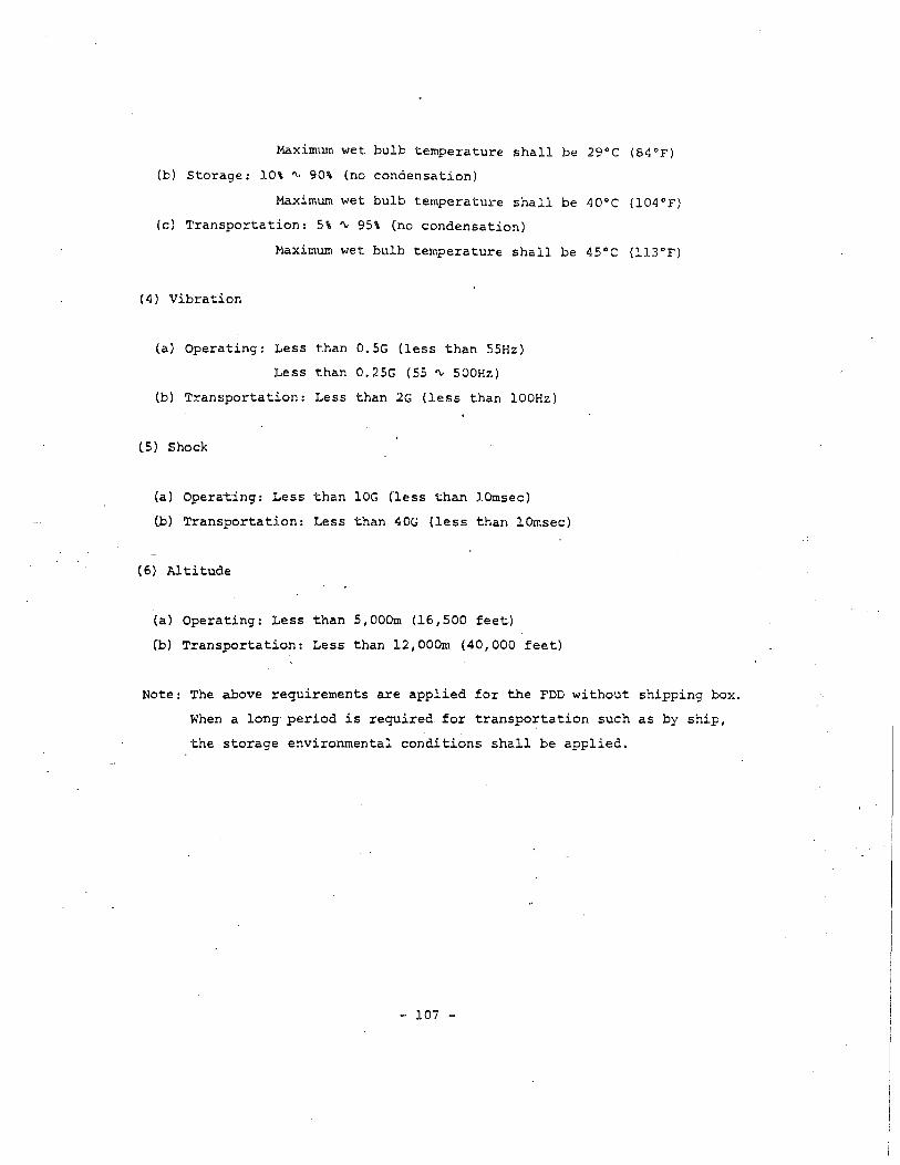
Maximum wet bulb temperature shall be 29°C (84°F)
(b) Storage: 10\ ~ 90\ (no condensation)
Maximum wet bulb temperature shall be 40°C (104°F)
(c) Transportation: 5\ ~ 95\ (no condensation)
Maximum wet bulb temperature shall be 45°C (ll3°F)
( 4) Vibration
(a) Operating: Less than 0.5G (less than 55Hz)
Less than 0.25G (55 ~ 500Hz)
(b) Transportation: Less than 2G (less than lOOHz)
lS) Shock
(a) Operating: Less than lOG (less than lOmsec)
(b) Transportation: Less than 40G (less than lOmsec)
(6) Altitude
(a) Operating: Less than 5,000m (16,500 feet)
(b) Transportation-: Less than 12,000m (40,000 feet)
Note: The-above requirements are applied for the FDD-without shipping box.
When a long period is required £or transportation such as by ship,
the storage environmental conditions shall be applied.
- 107 -

1-6. OPERATIONAL OIARACTERISTICS
(1) Data capacity
Recording method FM MFM
Data transfer rate (K bits/sec) 250 500
Tracks/disk 154 (160) 154 (160)
Innermost track''bit density (bpi) 4,823 (4,935) 9,646 (9 ,870)
Innermost track flux density (frpi) 9,646 (9 ,870) 9,646 (9 ,970)
Unformatted K bytes/track 5.208 10.416
K bytes/disk 802 1,604
26 sectors K bytes/sector 0.128 0.256
F Data 0 /track K bytes/track 3.328 6.656
capacity r m
K bytes/disk 512.5 (532.5) 1,025.0 (l,065.0)
a K bytes/sector 0.256 0.516 15 sectors
t /track K bytes/track 3.840 7.680
t e K bytes/disk 591.4 (614.4) 1,182.7 (1,228.8) d
K bytes/sector 0.512 1.024 8 sectors /track K bytes/track 4 .096 _8 .192
K bytes/disk 630.8 (655.4) l- -261. 6 •• .1 (l,310.7)
Note: Up to 80 cylinders are available for the FDD. The figures in the blackets are for 80 cylinder's operation (160 tracks).
(Table 102) High density mode data capacity
- 108 -
,,. '.
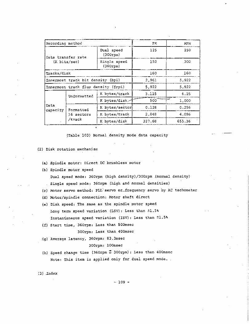
Recording method FM
Dual speed 125
Data transfer rate (300rpm)
{K bits/sec) Single speed 150 (360rprn)
Tracks/disk 160
Innermost track bit density (bpi) 2,961
Innermost track flux density (frpi) 5,922
Unformatted K bytes/track 3.125
K bytes/disk./ - 5oci_, -'
Data K bytes/sector! 0.128
capacity Formatted 16 sectors K
' bytes/trac~ 2.048
/track K bytes/disk 327.68
(Table 103) Normal density mode data capacity
(2) Disk rotation mechanism
_(a) _spindle motor: Direct OC b:r:ushless motor
(b) Spindle motor speed
MFM
250
300
160
5,922
5,922
6.25
1,000
0.256
4.096
655.36
Dual speed modec: 360rpm (high density)/300rpm (normal density)
Single speed mode: 360rpm (high and normal densities)
(c) Motor servo method: PLI/ servo_or--±r.equency servo by AC tachometer
(d) Motor/spindle connection: Motor shaft direct
(e) Disk speed: The same as the spindle motor speed
Long term speed variation (LSV): Less than ±l.5%
Instantsneous speed variation (ISV): Less than ±l.5%
(f) Start time, 360rpm: Less than SOOmsec
300rpm: Less than 400msec
~(g)--Av-era-ge latency, 360rpm: 83. 3msec
300rprn: lOOmsec
(h) Speed change time (360rprn t 300rpm): Less than 400msec
Note: This i tern is applied only for dual speed mode. .
(3) .Index
- 109 -

(a) Number of index: l per disk revolution
(b) Detection method: LED and photo-transistor
(c) Detection cycle, 360rpm: l66.7msec ±1.5%
300rpm: 200msec ±l.5%
(d) Index burst detection timing tolerance (with specified test disk)
360rpm: ±l65µsec, Max.
300rpm: ±200µsec, Max.
(4) Track construction
(a) Track density: 96tpi
(b) Number of cylinders. high density· mode: 77 (80) cylinders
normal density mode: 80 cylinders
(c) Number 0£ tracks, high density mode: 154 (160) tracks
normal density mode: 160 tracks
(d) Outermost track radius (track 00): Side 0 57.150mrn (2.2500 in)
Side l 55.033rnrn (2.1667 in)
(e) Innermost track radius
For 77 cylinders (track 76): Side 0 -37. 042mrn (l.4583 in)
Side l 34.925mrn (l. 3750 in)
For 80 cylinders (track 79)~ Side 0 36.248mrn (l .4271 in)
Side l 34.13lmrn (l.3~38 in)
(f) -Po-sitioning---accura-cy: Le-s-s--than ±20µm, with -speci-fied test disk
(Track 32, 23 ± 2-<>c, 40 rv 60%RH)
(5) Magnetic head
(a) Magnetic head: Flexure supported read/write head with tunnel erase,
2 sets.
(b) Effective track width: O.J.5-5 ± O.OlSJ!\Ill __ (0.0061. ± 0.0006 in)
(c) Read/write-erase gap spacing: 0.585rnrn (0.0230 in), Norn.
(d) Read/write gap azimuth: 0° _± J.8', with specified test disk.
(6) Track seek mechanism
.. 110 -
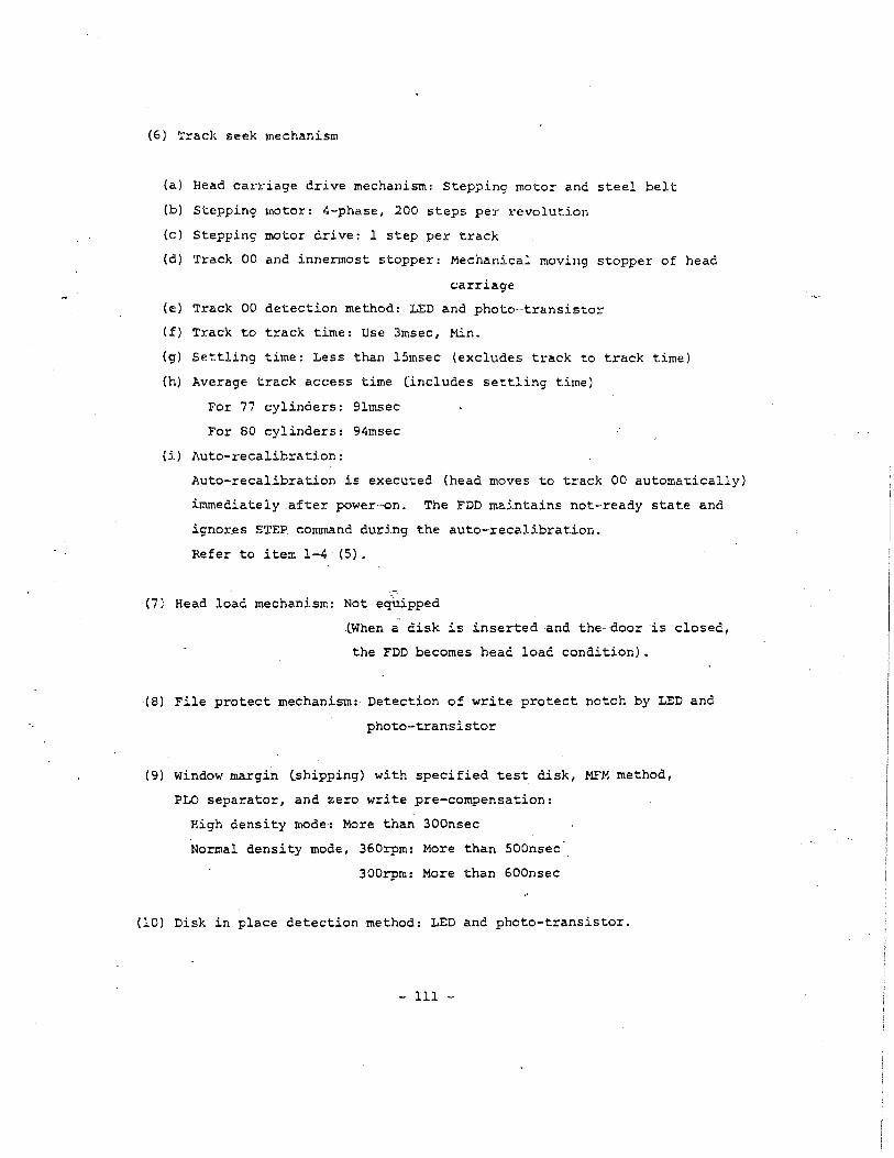
(6) Track seek mechanism
(a) Head carriage drive mechanism: Stepping motor and steel belt
(b) Stepping motor: 4-phase, 200 steps per revolution
(c) Stepping motor drive: l step per track
(d) Track 00 and innermost stopper: Mechanical moving stopper of head
carriage
(e) Track 00 detection method: LED and photo-transistor
(f) Track to track time: Use 3msec, Min.
{g) Settling time: Less than 15msec (excludes track to track time)
(h) Average track access time (includes settling time)
For 77 cylinders: 9lmsec
For 80 cylinders: 94msec
{i) Auto-recalibration:
Auto-recalibration is executed (head moves to track 00 automatically)
immediately after power-on. The FDD maintains not-ready state and
ignor~s STEP command during the auto-recalibration.
Refer to item 1-4 (5).
(7) Head load mechanism: Not equipped
(When a disk i~ inserted ~nd the-door is closed,
the FDD becomes head load condition).
(8) -File protect mechanism: Detection of write protect notch by LED and
photo-transistor
(9) Window margin (shipping) with specified test disk, MFM method,
PLO separator, and zero write pre-compensation:
High density mode: More than 300nsec
Normal density-mode, 360:rpm: More than SOOnsec
300rpm: More than 600nsec
(10) Disk in place detection method: LED and photo-transistor.
- 111 -

1-7. RELIABILITY
( 1) MTBF: 10, 000 power on hours or more (for typical usage).
(2) MTTR: 30 minutes
(3) Design component life: 5 years
(4) Preventive maintenance: Not required (for typical usage)
(5) Error rates
(a) Soft read error: 1 per 109 bits (up to 2 retries)
(b) Hard re~ bits
(c) Seek error: 1 per 106 seeks
(6) Safety standard: Complying with UL, CSA
warning: EMl/RF! countermeasure
This FDD generates and uses radio frequency energy. If the FDD (including the interface cable and connector) i.s used··wi thout shielding, it may cause interference to radio and television reception around it. Be -"Sure to install .this FDD in the equipment which is designed
--for effective EMl/RF! countermeasure.
This FDD ins.t.a.lled in a .:;pecific equipment has been type tested and found to comply with the limits for a Class B computing device in accordance with the specifications in Subpart J of Part 15 of FCC Rules, which are designed to provide reasonable protection against such lnterlerence in a residential installation.
-However, there ~s-no--guarantee -that interference will not occur in a particular installation. If_ the equipment_with this.FDD does cause interference to radio. cor .television ~eception.1--which can be determined
--.0y turning the equipment off and on, the user is encouraged to try to correct the interference by one or more of the following measure.
a) Reorient the receiving antena.
b) Relocate the equipment-with respect to the receiver.
c) Move the equipment away from the receiver.
d) Plug the equipment into a different outlet so that the equipment and -the receiver are on different branch circuits.
- 112 -
i --1
I

1-8. SIGNAL INTERFACE
1-8-1. Electrical Characteristics
(1) Interface driver/receiver: See Fig.102.
(2) Electrical characteristics
The following specifications are applicable at the signal connector of
the FDD.
(a) Input signal
LOW level (TRUE): OV ~ O.SV
Terminator current: 5.25 x l,000
_T_e_rm_i_n_a_t_o_r_r_e_s-'-"i_s_t_o_r_v_a_l_u_e_ mA' Max·
Receiver current: 0.4mA, Max.
HIGH level (FALSE): 2.SV ~ 5.25V
(b) output signal
LOW level (TRUE): OV ~ 0.4V
Driver~ink current capability: 48mA, Max.
HIGH level (FALSE): 5.25V, Max.
(depending on host side terminator)
(3) Terminator
(a) Resistor value: See Table 100 in item 1-1.
(b) Terminator for DRIVE SELECT 0 ~ 3 input signals:
A terminator resistor is mounted on the PCB with soldering joint.
(c) Terminator for other input signals:
A resistor network is mounted on IC socket on the PCB.
(d) Shipping condition
All of the terminator resistors are mounted.
- 113 -
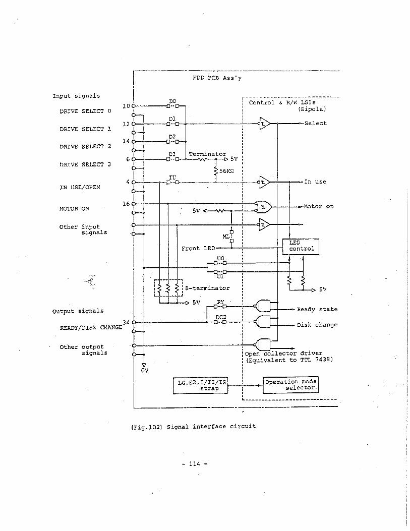
Input signals
DRIVE SELECT
DRIVE SELECT
DRIVE SELECT
DRIVE SELECT
IN USE/OPEN
MOTOR ON
Other input signals
Output signals
Other output signals
0
l
2
3
,- FDD PCB Ass'y I
I DO r---------------------------100 D··
: Control & R/W LSis l (Bipola)
12
14
6
4
16
I
I
I
I I
ov
I I I -o-_,.. _______ _:.•---eu>-------select
D-----i\A,f>.----0 5 v
56Krl
-o------>-----:.--.ci u >--+----In use
Front LED---~.._-!.,-------1-~ I
~I~
LED cont.rel
r --- -- . ., ' I I I .__ -- --
I
: a-terminator I
_J ----1> 5V
I I
: Open collector : (Ecruivalent to I -I I I I
driver TTL 7438)
, LG,E2,I/II/IS~-"'-: __ ~operation mode L _____ ~:·P L_ ___________ ::~~:-t~:-:_-_-_-_--_
(Fig.102) Signal interface circuit
- 114 -

1-8-2. Signal Connector and Cable
(1) Signal connector
(a) FDD side connector: Card edge of the main PCBA
(b) Pin numbers & pin pitch: 34 pins, 2.54mm (O.l in) pitch
(17 pins on both sides, even number pins are bottom side of the FDD)
{c) Polarizing key location: Between pins 4 and 6
(d) Card edge dimensions: See Fig.103
/~rface connections: See Table 102
, {f) Cable side matched connector:
3M, Scotchflex ribbon connector, P/N 3463-0001
or AMP, thin leaf connector, P/N 583717-5 and contactor P/N 1-583616-1
or equivalent.
{ 2) -Maximum interface cable length:
For the. multiplex connection by daisy chaining, the total-cable-length
should -be less ·than as -fol1ows:
e.g.: 3m, Max. for 330rl terminator, 1..Sm, Max. for lKn terminator
' .. ,, 0.91 Key slot
I I I I - - - - -
-f - - - --
- - .
·If\ . Pin 2-
.-1 -Pi r- .-1 - n 34
I I I
' I I I
2.4 I 2.54 I I I ' ""I
1.4 2.4 I
45.44
(Units: mm) Notes: 1. PCB thickness: l.6mm, Nam.
-2. _The figure shows bottom view of the FDD.
(Fig.103) Card edge dimensions of signal connector
- 115 -
/ I \
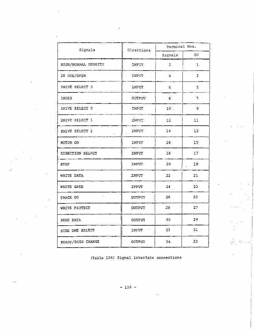
Terminal Nos. Signals Directions
Signals ov
HIGH/NORMAL DENSITY INPUT 2 1
IN USE/OPEN INPUT 4 3
DRIVE SELECT 3 INPUT 6 5
INDEX OUTPUT 8 7
DRIVE SELECT 0 INPUT 10 9
DRIVE SELECT 1 I INPUT 12 . 11
DRIVE SELECT 2 INPUT 14 13
.MOTOR ON I INPUT 16 15
DIRECTION SELECT I INPUT 18 17
STEP ..
INPUT 20 19
WRITE DATA I _INPUT 22 21
WRITE GATE INPUT 24 23
TRACK 00 I OUTPUT 26 25
WRITE PROTECT OUTPUT 2B 27
READ DATA I OUTPUT 30 29
SIDE ONE SELECT INPUT 32 31
READY/DISK CHANGE OUTPUT 34_ _33_
(Table 104) Signal interface connections
- 116 -

1-8-3. Input/Output Signals
In the following, input signals are those transmitted to the FDD
while output signals are those transmitted from the FDD.
Refer to item 1-12 as to the relation between input signals and
operating conditions of the front bezel indicator and spindle motor.
LOW level of the signals is TRUE.
(l) DRIVE SELECT 0 ~ 3 input signals
(a) Signals of four lines to select a specific FDD for operating in
multiplex control by daisy chaining.
(b) Only the DRIVE SELECT signal of the same number as of on-state strap
among DO~ D3 straps is effective.
(c) All the input/output signals except "for the MOTOR ON, IN USE, and
BIGH/NORMAL DENSITY signals are effective when this signal is
~ffectively received.
(d) The-time required to make each input or output signal effective after
the transmission-of this signal is ~.Sµsec, Max. including delay.time
through the. interfacP. -cable.
(2) MOTOR ON input signal
(a) Level signal to rotate the spindle motor.
(b) The spindle motor reaches to the rated rotational speed within SOOmsec
(.at 360rpm) or 400msec Cat 300rpm) after this signal changes to TRUE.
(c) Rotational speed is switched between 360rpm and 300rpm according to
the HIGH/NORMAL DENSITY signal only when the dual speed mode is
selected. Refer to items 1-11 and 1-12-3.
(3) DIRECTION SELECT input signal
(a) Level signal to define the moving direction of the head when the STEP
line is pulsed.
- 117 -
.,..··
i I
.l ./
(b) Step-out (moving away from the center of the disk) is defined as HIGH
level of this signal. Conversely, step-in (moving toward the center
of the disk) is defined as LOW level of this signal.
(4) STEP input signal
(a) Pulse signal to move the head. The pulse width shall be more than
0.8µsec and the head moves one track space per one pulse.
(b) The access motion (head seek operation) is initiated at the trailing
edge of a STEP pulse. For the subsequent motion in the same direction,
the pulses should be input with an interval of more than 3msec, while
the pulses should be input with an interval of more than lOmsec for
a direction change.
(c) This signal is ineffective when the WRITE PROTECT signal is FALSE and
the WRITE GATE signal is TRUE.
Also this signal is ineffective when the TRACK 00 signal is TRUE and
the DIRECTION SELECT signal is HIGH level (step-out).
(d) This signal shall be input according to the timing in Fig.104.
(5) WRITE GATE input signal
(a) -Level signal to era-s-e the written data and to enable the writing of
_new _data~
(b) The FDD is set to write mode when the following logical expression is
satisfied.
WR'.ITE GATE * DRIVE SELECT * WRITE PROTECT
(c) This signal should be made TRUE after satisfying all of the following
conditions.
i) The FDD is in ready-state (refer to item (13)).
However, the host controller can ignore this item since the INDEX
and the READ DATA pulses Qre output only when the FDD is in ready
state.
ii) More than l8msec after the effective receival of the final STEP
pulse.
- 118 -
iii) More than lOOµsec after the level change of the SIDE ONE SELECT
signal.
iv) More than 400msec after the level change of the HIGH/NORMAL DENSITY
signal.
(This item is applied only to the dual speed mode).
(d) None of the following operation should be done for at least 590µsec
(at 360rpm) or lmsec (at 300rprn) after this signal is changed to
FALSE.
i) Make a motor-on command FALSE.
ii) Make the DRIVE SELECT signal FALSE.
iii) Start the head seek operation by the STEP pulse.
iv) Change the level of the ~IDE ONE SELECT signal.
v) Change the level of the HIGH/NORMAL DENSITY signal.
(This item is applied only to the dual speed mode).
(6) WRITE DATA input signal
(a) Pulse signal to designate the contents of data to be written on a
disk. The pulse width should be 0.07 "'l.lµsec {at high density mode)
or 0.07 "'2.lµsec (at nonnal density mode) and the leading edge of the
pulse is used.
(b) This signal is ineffective -while either of the following condition is
-.sati.sfied~
i) The WRITE GATE signal is FALSE.
ii) The WRITE PROTECT signal is TRUE.
(c) This signal shall be input according to the timing in Fig.105.
(7) SIDE ONE SELECT input signal
(a) Level _signal to designate -which side of a double sided disk is--used .for
reading or writing.
(b) When this signal is HIGH level, the magnetic head on the side 0 surface
of the disk is selected, while the magnetic head on the side l surface
is selected when this signal is LOW level.
- 119 -
(c) The :READ DATA pulse on a selected surface is valid more than lOOµsec
after the change of this signal level.
(d) Write operation {the WRITE GATE signal is TRUE) on a selected surface
shall be started rnore than lOOµsec after the change of this signal
level.
(e) When the other side of a disk is selected after the completion of a
write operation, the level of this signal shall be switched more than
590µsec (at 360rprn) or lrnsec (at300rprn) after making the WRITE GATE
signal F.ALSE.
(8) IN USE/OPEN input signal
This signal is effective only when the IU strap is on-state. Refer to
item 1-11.
{a) Level signal to indicate that all of the daisy chained FDDs are in
use condition under the--control of the host system. Refer to i tern
1-12.
(b) When the 10 strap is off-state, only the terminator is connected to
pin 4 of the signal interface connector.and the input circuit becomes
open condition.. _Refer to Fig .·102.
- 120 -

(9) TRACK 00 output signal
(a) Level signal to indicate that the head is on track 00 (the outermost
track).
(b) This signal is valid more than 2.Bmsec after the effective receival
of the STEP pulse.
(10) INDEX output signal
~-------./
(a) Pulse signal to indicate the start point of a track,..~nd one INDEX
pulse per one disk revolution is 9utput.
(b) INDEX pulse is output when the following logical expression is
satisfied.
Index hole detection * DRIVE SELECT * Ready state * Seek-complete
Notes: l. Eeek-complete means the state that more than lSmsec through
17msec has been passed after the trailing edge of the final
STEP pulse'.
2. Refer to item 1-11 "E2 strap" as to the output condition
change of the INDEX pulse.
(c) Fig.106 shows the timing of this signal. Leading edge of the-pulse
shall be used as the reference and all the output pulses are valid.
(11) READ DATA output signal
{a) Pulse signal for the read data from a disk composing clock bits and
data bits together.
(b) Fig.107 shows the timing for this signal. Leading edge of the pulse
shall be used as the reference.
{c) READ DATA pulse is output when the following logical expression is
satisfied.
Read data detection * DRIVE SELECT * Ready state * Write operation
* Seek-complete
Notes: 1. Seek-complete means the state that lSmsec through 17rnsec
has been passed after the trailing edge of the final STEP
pulse.
- 121 -

2. Write operation means the state that the WRITE GATE signal
is FALSE and more than the erase delay time (lmsec, Max. at
300rpm or 590µsec, Max. at 360rpm), has been passed after
the WRITE GATE signal changed to FALSE.
3. Refer to item 1-11 "E2 strap" as to the output condition
change of the READ DATA pulse.
(d) Output pulse is valid when all of the following conditions are
satisfied.
i) More than lBmsec after the effective receival of the final STEP
pulse.
ii) .More than 590µsec (at 360rpm) or lmsec (at 300rpm) after the
WRITE GATE signal becomes FALSE.
iii) .More than lOOµsec after the level change of the SIDE ONE SELECT
signal •.
vi) More than 400msec after the level change of the HIGH/NOR.t.JAL
DENSITY signal.
(This ±tern cis applied only-to the -dual -speed mode).
(12) WRITE PROTECT output signal
(a) Level signal to indicate that the write enable notch of the disk
is masked.
-ch) When this signaT is TRUE, the data on the disk are_protected from
erasing and writing of new data is inhibited.
(13) READY/DISK CHANGE output signal
This signal has either READY or DISK CHANGE function by selecting the
RY/DC2 strap. Refer to Fig.102 and items 1-11 and 1-12-3.
(l3-l) When READY function is selected:
(a) Level signal to indicate that the FDD is in ready state.
(b) The FDD goes to the ready state when all of the following conditions
are satisfied.
- 122 -
i) The FDD is powered on and a disk is installed.
ii) A motor-on command from the host side is TRUE and 500msec has been
passed.
iii) The disk rotates at more than 80% of the rated speed and two INDEX
pulses have been counted.
iv) INDEX pulse width is less than 13rnsec.
(c) The FDD goes to the ready state within 730rnsec (at 360rpm) or within
800msec (at 300rpm) after making a motor-on command TRUE. 510rnsec,
approx. in average.
(d) The ready state .is reset within 0.3rnsec after changing the level of
a motor-on command to FALSE.
(e) INDEX and READ DATA output signals maintain FALSE while the FDD is
not in the ready state.
(f) When the dual .speed ll\Ode is .selected with the :r strap being on-state,
the FDD is reset to not-ready state within 30µsec after the level
change of the HIGH/NORMAL DENSITY input signal. If a motor-on command
maintains TRUE at that time, the FDD returns-to ready state within
600msec again.
(g) When the single speed mode is selected or~when the dual speed mode -.. ~.
:is selec'ted with the IS strap being on-state, -FDD maintains the
ready state with no relation to the ~evel change-of the HIGH/NORMAL
DENSITY input signal. Refer to i terns l-11 and 1-12-~.
(13-2) When DISK CHANGE function is selected:
(a) Level signal to indicate that an installed disk is removed
ldisk change state).
(b) This signal goes to TRUE when either of the following conditions are
satisfied.
i) Power on.
ii) Disk is removed.
(c) This signal returns to FALSE when both o( the following conditions
are satisfied.
i) Disk is installed.
ii) A STEP pulse is received when the DRIVE SELECT signal (selected
- 123 -
by DO ~ D3 straps) is TRUE.
(14) HIGH/NORMAL DENSITY input signal
(a) Level signal to switch the operation mode of the FDD.
(b) When the LG strap is on-state, the LOW level of this signal
designates the high density mode, while the HIGH level designates the
nonnal density mode.
(c) When the LG strap is o_;J~~e-LOW.,.,l.evel of this signal
designates the norma.1' density mode, while the HIGH level designates
the high density mode.
(d) If the dual speed mode.is selected, disk rotation speed is switched
between 360rpm (high density mode) and 300rpm (normal density mode)
according to this signal level.
(e) If the single speed mode is selected, disk rotation spe€d is fixed
to 360rpm independent of this signal level.
- 124 -

Note: Treatment of not-used signals
If some of the provided input/output signals are not necessary for
your application, keep them open or connect appropriate pull-up
resistor (more than 1500 for an FDD output signal) at the host side.
- 125 -

WRITE GATE __j Ste];l-QJ.lt
I~ DIRECTION SELECT I Steo-in ___ .J --STEP
t
t
5 s Min. 5µs
3ms Min.
t= o.avs,Min. tl= 590µs, Min. (360rpm)
lms,Min. (300rprn)
WRITE GATE
-WRITE~~DATA
Magnetization on disk
Density & Disk
High,360rpm
Normal, 360rpm
Nonnal,300rprn
(Fig.104) STEP timing
---"'o_ _o ____ ...;l _-'""'o __
t2
t3 t tS 5 I * * * *
*:±0.5%
Speed t2 t3 t4 t5
0. 07-vl. lµs 4µs,Max. 2µs,Norn. 3µs,Nol:\.
0. 07""~. lµs -6-:/µ s, Max. 3;3us,Norn. Sus,Nom.
0.07-v2.lµs 8µs,Max. 4µs., Norn. 6us,Nom. -
(Fig.105) WRITE DATA timing (MFM method)
- 126 -
Min.
t6
4us,Norn
6.7µs,Nom.
Bµs,Norn.
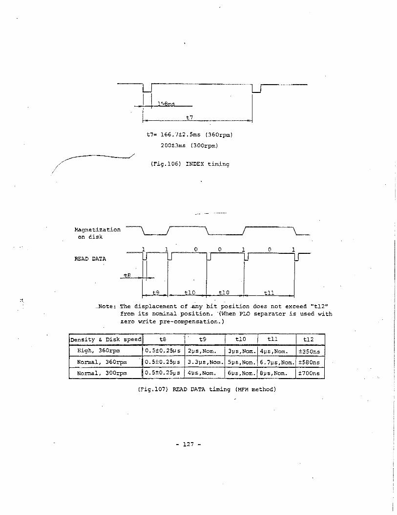
I I l'\.Sms
t7= 166.7±2.Sms (360rpm)
200±3ms (300rpm)
(Fig.106) INDEX timing
.Magnetization -----, / \,__. _ __,
on disk
\ ____ __,/ \_
,.._ _ __,1 .-----o-.., .,._o ___ _,1 ___ 0 ___ ~1
READ DATA
8
9 tlO tlO tll
-Note-: The displacement of any bit position does not exceed "tl2" from its nominal _position. -(when PLO separator is used with zero write pre-compensation.)
Density & Disk speed tB t9 tlO tll tl2
High, 360rpm 0.5±0.25µs 2µs,Nom. 3µs,Norn. 4µs,Nom. ±350ns
Normal, 360rpm 0. 5±0. 25µ s 3.3µs,Nom. 5µs,Nom. 6.7µs,Nom. ±580ns
Nomal, 300rpm 0. 5±0. 25µ s 4µs,Nom. 6µs,Nom. Sµs,Nom. ±700ns
(Fig.107) READ DATA timing (MFM method)
- 127 -

1-9. POWER INTERFACE
Refer to item 1-4 for power requirements.
(l) Power connector
(a) FDD side connector: AMP, Mate-N-Lock connector, P/N 172349-1
or equivalent
(b) Pin numbers: 4 pins
(c) Protection method ~or mis-connection: Mechanical protection by the
shape of the connector housing.
(d) Pin location: See Fig.108
(e) Power interface connections: See Table 105
(f) Cable side matched connector: AMP, P/N 1-480424-0 and pins 60617-1,
or 60619-1,
or equivalent
(2) Power cable
Any appropriate cables taking the maximum power consumption of the FDD
and the power voltage at the connector into.consideration will be
acceptable.
PCBA .
~ li ~"~ ~ ~ )[1-:---Power connector
4 3 2 l ------Terminal Nos.
· (Fig.108) Power connector pin location (rear -view)
- 128 -
.,._ ..

Voltage Terminal Nos.
OC+l2V l
ov 2
ov 3
OC+SV 4
(Table 105) Power interface connections
- 129 -

1-10. FRAME GROUNDING
(1) Frame grounding
(a) The FDD frame is electrically connected to DC OV by FG strap on the
main PCBA. (See Fig .109).
(b) The FDD is shipped with the FG strap set to on-state.
(c) Insulation resistance between the frame and DC OV is more than 150Kll
at DC 150V, if the FG strap is set to off-state.
(2) Frame ground terminal (back side of the FDD)
(a) FDD side tenninal: AMP Fasten l87 tab P/N 61761-2
or equivalent
(b) ~able _side-matched terminal: AMP P/N 60972-2 or 61697-1
or equivalent
connector (OV)
L_ ground terminal
PCBA mounting screw
(Fig.109) Frame ground internal connection
- 130 -
·.· :·

l-11. CUSTOMER SELECTABLE STRAPS
All the straps are mounted on the main PCBA of the FDD. Insertion of
a short bar onto the post pin is defined as the on-state of the strap.
Fig.110 shows the assignment of the straps on the PCBA.
I~IS ~II
LG lo-ol
·E2 lo-ol
0 0 0 0 D D I f I t I I
D 0 0 O D D
r9JDC2
IUs-D l9J .ML 0-0
RY 0-0 .
(Fig .110) Assignment of straps
(1) Straps setting at shipment
See Table 100 in i tern 1-1.
(a) In the multiplex control by daisy chaining, these straps designate
the address of the FDD.
(b) By the combination with the DRIVE SELECl' 0 ~ 3 signals, four addresses
of 0 through 3 can be designated. Refer to Fig.102 and item l-8-3 (1) •
. Never designate nore than 2 FDDs to a same address.
(3) UO and Ul straps
(a) Straps to select the turn-on condition of the front bezel indicator.
- 131 -
,. ./

(b) Five turn-on conditions can be selected including the IU strap in
item (4). Refer to item 1-12-1.
(4) IU strap
(a) Strap to make the signal interface terminal 4 be used for the IN USE
input signal.
(b) When this strap is off-state the input circuit is open and the IN USE
input signal is ineffective. Refer to Fig.102.
(5) ML strap
{a) Strap to select the rotational condition of the spindle motor by
an external command.
(b) When this strap is off-state, the spindle motor rotates only -by the
MOTOR ON input signal.
(c) When this strap is on-state, the spindle motor rotates by either ~f
the following conditions. (Refer to -item 1-12-2).
i) .While the MOTOR ON input signal is TRUE.
ii) Whil~ the front bezel indicator turns on.
(6) RY and DC2 straps
(a) Straps to select the function of the READY/DISK CHANGE output signal
· (signal interface terminal 34).
(b) When the RY strap is on-state, the signal of terminal 34 functions as
the READY signal, while it functions as the DISK CHANGE signal when
the DC2 strap is on-state. Refer to item l-8-3 (13).
(7) LG strap
(a) Strap to select the meaning of the HIGH/NORMAL DENSITY input signal
level.
(b) When this strap is on-state, the LOW level of the HIGH/NORMAL DENSITY
- 132 -

signal designates the high density mode.
(c) When this strap is off-state, the LOW level of the HIGH/NORMAL DENSITY
signal designates the normal density mode.
(8) I/II/IS straps
(a) Straps to select the speed mode of the FDD.
(b) When the I strap is on-state, the dual speed mode is designated.
Disk rotational speed is switched between 360rpm for the high density
mode and 300rpm for the normal density mode according to the
HIGH/NORMAL DENSITY signal. Also the ready state is reset once
synchronizing with the HIGH/NORMAL DENSITY signal. Refer to item
1-8-3 (13-l).
(c) When the II strap is on-state, the single speed mode is designated.
Disk rotation speed is fixed to 360rpm independent of the HIGH/NORMAL
DENSITY signal.
(d) When the IS strap is-on-state, the dual speed mode is selected like
item (b). Eowever, the FDD maintains the ready state with no relation
to the HIGH/NORMAL DENSITY signal .
. (e) One of the I/II/IS straps should be set to on-state.
(9) E2 strap
(a) Strap to-select the output condition-of the INDEX-and-the- READ DATA
pulses.
(b) When this strap is off-.sta te, these pulses are output as in i terns
1-8-3 (10) and (11).
(c) When this strap is set to on-state, output conditions are changed to
the following logical expression (not gated with seek-complete).
1NDEX: Index hole detection * DRIVE SELECT * Ready state
READ DATA: Read data detection * DRIVE SELEC~ * Ready state
* Write operation
(10) FG strap
- 133 -

(a) Strap to connect the FDD frame electrically to DC OV.
(b) Refer to item 1-10 as to the details.
- 134 -
· ... :;~~
1-12. OPERATIONAL CONDITIONS
1-12-1. Front Bezel Indicator
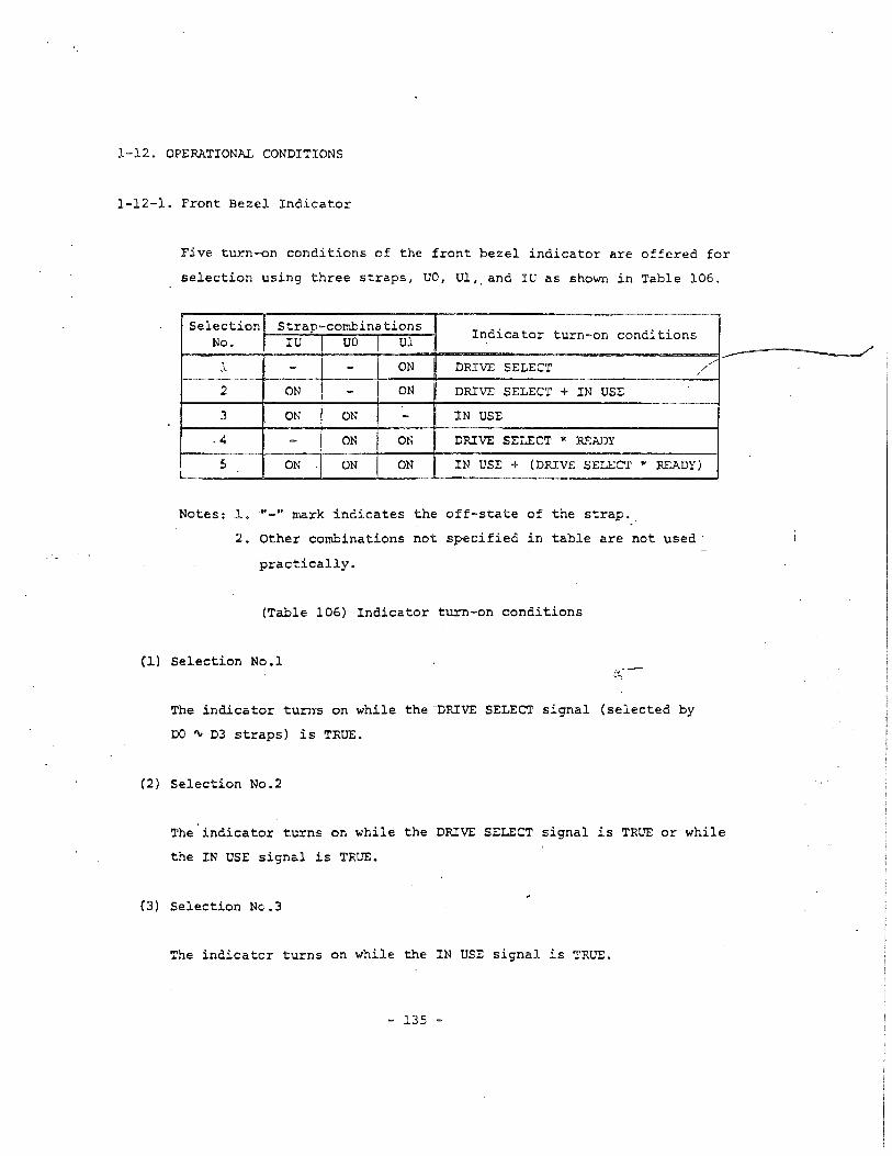
Five turn-on conditions of the front bezel indicator are offered for
selection using three straps, UO, Ul,, and IU as shown in Table 106.
Selection Strap-combinations Indicator turn-on conditions No. IU uo Ul
l - - ON DRIVE SELECT /
2 ON - ON DRIVE SELECT + IN USE
3 ON ON - !N USE
.4 - ON ON DRIVE SELECT * READY
5 ON ON ON I
IN USE + (DRIVE SELECT * READY)
Notes: J.. "-" mark indicates the off-state of the strap ..
2. Othe~ combinations -not specified in table are not used ·
practically.
(Tabl~ 106) Indicator turn-on conditions
(1) Selection No.l
~he indicator turns on while the DRIVE SELECT signal (selected by
DO ~ D3 straps) is TRUE.
(2) Selection No.2
/
The indicator turns on while the DRIVE SELECT signal is TRUE or while
the IN USE signal is TRUE.
(3) Selection Nc.3
The indicator turns on while the IN USE signal is TRUE.
- 135 -

(4) Selection No.4
The indicator turns on while the DRIVE SELECT signal is TRUE and the
FDD is in ready state (refer to item l-8-3 (13)).
(5) Selection No.5
The indicator turns on in the condition cf item (3) or (4).
- 136 -

1-12-2. Spindle M::ltor
The spindle motor starts rotation in either of the following conditions
(1) and (2).
(1) Rotation by a command from the host side
Either one of the following conditions can be selected by the ML strap.
(a) Selection l: Off-state of ML strap
The spindle motor rotates while the following logical expression is
satisfied.
MOTOR ON ~ Disk installed
(b) Selection 2: On-state of ML strap
The spindle motor rotates while the following logical expression is
satisfied.
(MOTOR ON + Front bezel LED on) * Disk installed
Note that the Selection Nos.4 and 5 of the turn-on conditions of the • -P,.~·
£rent.bezel indicator (refer to item 1-12-1) cannot be used for this
purpose.
-(2) Automatic _rotation-by the __internal-circuit of the FDD
(a) Automatic rotation by the internal circuit will start when a disk
is inserted into the front bezel.
(b) Automatic rotation will stop under one of the following conditions.
i) When the front lever is closed, disk starts rotation, and the FDD
goes to ready state. The READY signal maintains FALSE.
ii) When a disk is removed.
iii) In a rare case, when a disk is inserted at the index hole
position and the front lever is not closed for 8.7 seconds, approx.
- 137 -
,. /

l-12-3. Operation Mode
Following operation modes are offered for selection using three strap
blocks, LG, I/II/IS, and RY/DC2 as shown in Table 107.
Three strap blocks operate independently each other.
Strap blocks ON Operation modes
LG LG LOW level of HIGH/NORMAL DENSITY signal designates high density mode.
- LOW level of HIGH/NOR"1AL DENSITY -~gnat.es. normal density mode (write current is reduced).
I/II/IS I Dual speed mode is selected. ·Ready state is reset synchronizing with HIGH/NORMAL DENSITY signal. 360rpm: High density, 300rpm: Normal density
n Single speed mode is selected. 360rpm: High/normal densities
IS Dual speed mode is selected. Ready state ..
maintains TRUE independently of HIGH/NORMAL DENSITY signal. 360rpm: High density, 300rpm: Normal density
RY/DC2 RY READY output is selected for ·signal interface terminal 34.
DC2 DISK CHANGE output is selected for signal interface terminal 34.
(Table 107) Selection of operation mode
- 138 -
/

Otn'LIIIE
This 8pecifica~ion provides
Inormal d~itiea, double
referred to 8S the FDD).
a description for the TEAC FD-55GPft, 5.25·, high
sided .ini flexible disk drive (hereinafter
Mod.l n_e FD-SSGFR-7149 FD-SSGFR-7193 FD-SSGFIl.-7220
TEAC PIN 19307671-49 19307671-93 19307672-20
Bezel , lever color Gray (PC-AT) Beiqe (PS2) Black
Safety .ta~rd on label UL& CSA
Unformatted data capacity 1.6M/1M bytes
Track density 96tpi
Head load mechanism Not equipped. (eSS)
Front bezel shape TEAC standard
Front lever shape TEAe standard
~ED indicator color Green
Pop-up mechanism Not equipped.
Shield cover Not equipped.
Input signal terminator ikQ ± 5', unremovable
Customer selectable straps DO-D3, UO, Ul, IU, RYIDC, LG. £2, I
Strap setting at delivery Di, De
Other optional fu.nction Not elluipped.

PHYSICAL SPECIFICATION
(2) Height: 41.Jgm (1.63 in), NOm.
(3) Depth: 203ma (7.99 in), NGa.
(excludes proj.~ions of interface co~eC~r8)
(4) Weight: 1.00kg (2.20 lbs), MO.., 1.lOkg (2.43 lbsl, Max.
(5 I External view: SM Fig.1.
(6) COoling, Natural air cooling
(7) Mounting, Mounting for the following directions are acceptable.
(a) Fron~ loading, mounted vertieally.
(b) Front loading, mounted hori:loontally with spindle motor down.
(el Mounting angle in items (a) and (b) should be less than lS~ with front
bezel up.
Note: As to the other mounting direc~ions than the above will be consid
ered separately.
(SI Installation: with installation holes on the frame of the FDD.
Refer to Fig.l.
(9) Material of frame: Aluminum diecaat
(10) Material of front be.el: PPHOX (Xyron)
........-----.----------- .......'...--_...~._~.. ,_<__,.•~,.""""~d...,,"'_'"
pover connector
.......'"<>
'"
0.7
.....
10000 I;
21.B±0 5
I
"
B±O
Tappea no I es4-NO.5.32UNCdeptn 5e&cll EiieJ8)C2
Spindlemotor
--#......~--.-
Tapped noleS B-M3.depth 5(oottom-4,each sloew2}
<>...'"'"..
connector (co.rd edge)Prante qraundN3TAP
49000.5
1.5
Indicator(LED}
Front bezel
Disk insertion Yind~
front level(UnitC:lUl)
._---_._-- _ ... _-- - - - ---------
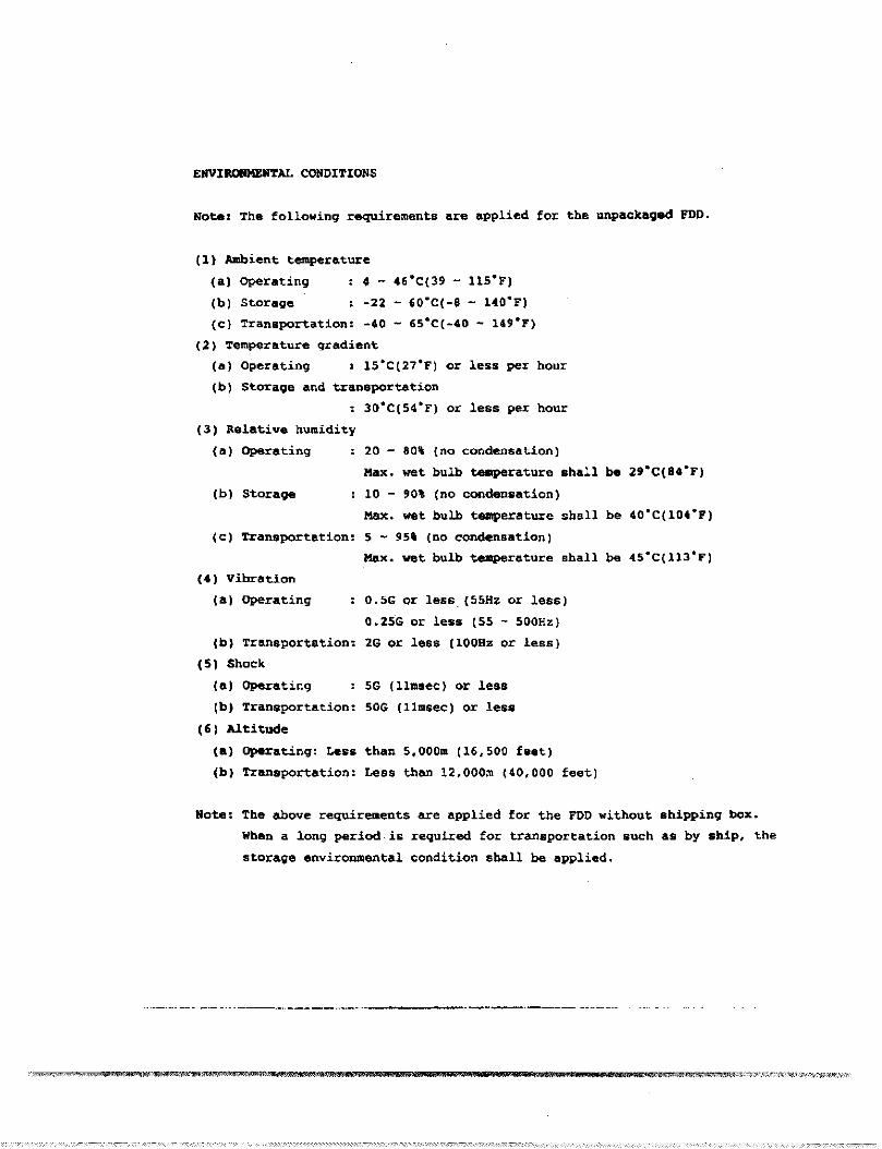
EIIVIROIIMEIITAL CONDITIONS
Note: The following requirements are applied for the unpackaged FDO.
(1) Amb'ent temperature
(al Operating • - C6'C(39 - 11S'F)
(b) Storage -22 - 60'C(-8 - lCO'F)
(e} Transportation: -40 - 6S·C(-40 - 149-F)
(2) Temperature gradient
(a) Operating : lS·C(27·F) or less per hour
(b) Storage and transportation
30·C(S4·F) or less per hour
(31 aelative humidity
(al Operating
(b) StoraQEI
(e) Transportation:
20 - 80% (no condensation)
Max. wet bulb temperature shall b. 29'C(8C'F)
10 - 90\ (no condensation)
Max. wet bulb temperature shall be CO'C(lOt'F)
5 ~ 95' (no condensation)
Max. wet bulb temperature shall be 4S'C(113'F)
O.5G Qr less, (55H~ or less)
0.2SG or less (55 - 500Hz)
2G or less (100Hz or less)
SG (llmsec) or less
SOG (llmsec) or less
(4) Vibrl'Jtion
(a) Operating
(bl Transportation:
(5) Shock
(al Operating
(b) Transportation:
(6) Altitude
(a) Operating: Less than
(b I Transportation: Less
S,OOOm (16,500 faat)
than l2.000m (40,000 feet)
Note: The above requirements are applied for the roo without shipping box.
When a long period.is required for transportation such as by ship, ~he
storage environmental condition shAll be applied •
..._._.. --- _.- _..._-_.._-----_.._---'-_._-_._--- -_ .._....
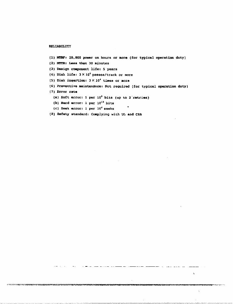
error: 1 per 10' bits (up to 2·ret.ries)
error: 1 per 101:1 bits
error: 1 per 10' seeks
stllndard:. Complying with UL and CSA
RELIABILI:rY
(1) _. ~O.OOO power on hours or more (for typical operation duty)
(2) HTTR: Less than 30 minutes
(3) Design c~Dent life' $ years
(4) Disk life t 3 X 10' passes/track or more
(S) Disk inllertion. 3 X 10' ti....s or lIore
(6) Preventive lISinten$nce, Not required (for typical operation duty)
(7) Error rate
(aJ Soft
(b) Hard
(eJ Seek
(81 Safety
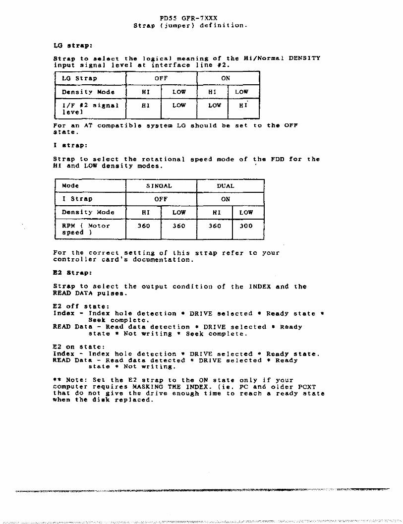
FD55 GFR-7XXXStra~ (jumper) definition.
LG strap:
Strap to select the logical meaning of the Hi/Normal DENSITYinput signal level at interface line '2.
LQ Strap OFF ON
Density Mode HI LOW HI LOW
IIF '2 sisnal HI LOW LOW HIlevel
For an AT compatible system LG should be set to the OFFstate.
I strap:
Strap to select the rotational speed mode of the FDD for theHI and LOW density modes.
Wode SINOAL DUAL
I Strap OFF ON
Density Mode HI LOW HI LOW
RPM ( Motor 360 360 360 300speed )
For the correct setting of this strap refer to yourcontroller card's documentation.
82 Strap:
Strap to select the output condition of the INDEX and theREAD DATA pulses.
E2 off state:Index - Index hole detection * DRIVE selected * ReadY state *
Seek complete.READ Data - Read data detection * DRIVE selected * Ready
state * Not writing * Seek complete.
E2 on state:Index - Index hole detection * DRIVE selected * Ready state.READ Data - Read data detected * DRIVE selected * Ready
state * Not writing.
** Note: Set the E2 strap to the ON state only if yourcomputer requires MASKING THE INDEX. (ie. PC and older PCXTthat do not give the drive enough time to reach a ready statewhen the di.k replaced.
,
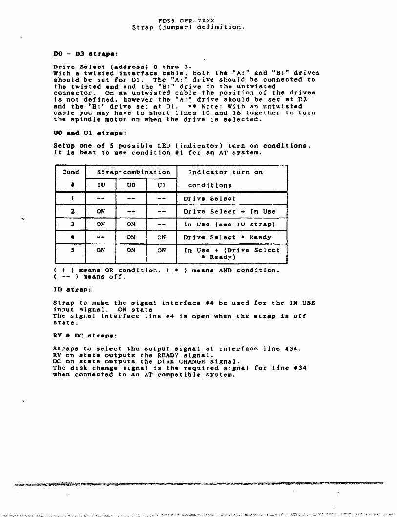
FDSS GFR-7XXXStrap (jumper) definition.
DO - D3 straps:
Drive Select (address) 0 thru J.With a twisted interface cable, both the "A:" and "8:" drivesshould be set for 01. The "A'" drive should be connected tothe twisted end and the "B:" drive to the untwistedconnector. On an untwisted cable the position of the drivesis not defined. bowever tbe "A:" drive should be set at D2and the "B:" drive set at 01. .* Note: With an untwistedcable you may have to short lines 10 and 16 together to turnthe spindle motor on when the drive is selected.
UO and Ul strapS:
Setup one of S possible LED (indicator) turn on conditione.It is best to use condition '1 for an AT system.
Cond Strap-combination Indicator turn en
• IV VO VI conditions
1 -- -- -- Drive Select
2 ON -- -- Drive Select .. In Use
3 ON ON -- In Usc (see IU strap)
4 -- ON ON Drive Select • Ready
S ON ON ON In Use .. (Drive Select
* Ready)
( + ) means OR condition. ( • ) means AND condition.( -- ) means off.
IU strap:
Strep to make the sisnel interfece '4 be used for the IN USEinput signal. ON stateThe signal interface line #4 is open when the strap is offstate.
RY ., DC straps:
Straps to select the output silnal &t interface line '34.RYan state outputs the READY signal.DC on stale outputs the DISK CHANGE signal.The disk chanae sianal is the required sillnal for line .34when connected to an AT compatible system.

FDS5 GFR-7XXX series FDDStrap {jumper) definition
> Strap (jumper) location on the printed circuit board.
PCBA
34
••
.,..~ ..
l~
<o[a al, la al
..~,. 'a _I
• ~ (I. VI
~1 2 3 "
(±)POWER
CONNECTOR
I-I~~~_ 2
INTERFACE CONNECTOR
> The factory strap (jumper) settings are:
D1 - Drive Select #1DC - Disk change signal output at line #34
This configuration will enable the drive to worl...as either an -A:- drive or a -B:- drive.
If the INTERFACE cable has a twist at the end.
> Power connector: #1 - 12 vdc#2 & #3 - Ovdc, ground#4 - 5 vdc
-------------------------

TEAC FD-55 Series51,4" 1.2 MB Floppy Disk Drive
hstallation Guide
S~'diskcl1c
lnsertiOD windowLever
Your FD-55 package includes:
o FD-SS floppy disk driveo Installation guide

Introdnction
Thank you fur purchasing thc TEAC FD-55 Series 1.2 MB floppy diskdrive. This product is intended for use in lBM@PClXT/AT@andcompatible computers.
This quality drive will provide trouble-free operation for your computer system if properly installed. PLEASE READ THE ENTIREINSTALLATION GUIDE THOROUGHLY BEFORE YOU BEGINTHE INSTALLATION. If you have questions or comments on theinstallation, please call TEAC Technical Support Center at thetelephone number listed on the back page of this Guide.
Tools You May Need
Depending on the design of your computer, you may need the followingtools to complete the installation.
~ a flat blade screwdriver \'\ ~\~ a Phillips screw.driver \' • ", '\ \~ needle-nosed phers, .,
Handling the FD-SS Series S'A" Drive
Your FD-55 series drive must be handled with care. Avoid applyingundue force or abnormal strain to the spindle motor. stepping motor orprinted circuit board. Avoid placing your fingers on the printedcircuit board. it is best to hold the FD-55 by the diecast frame. asindicated by the arrows in figure A.
Figure A
1
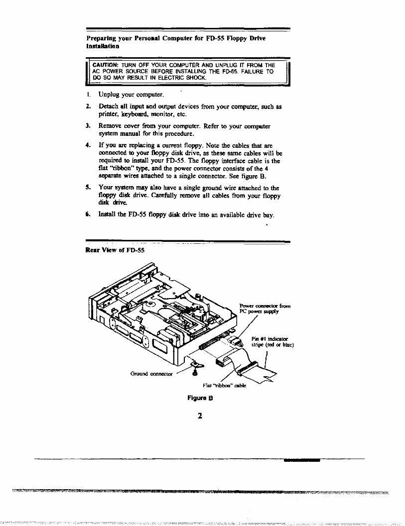
Preparing your Perso..1 Computer for FD-SS Floppy DrlveInstallation
CAIITIDN: TURN OFF YOUR COMPUTER AND UNPLUG IT FROM THEAC POWER SOURCE BEFORE INSTALLING THE F[).55. FAILURE TO00 SO MAY RESULT IN ELECTRIC SHOCK.
I. Unplug yuur computer.
1. Detach all input and output devices from your computer, such asprinter, keyboard, monitor. etc.
3. Remove cover from your computer. Refer to your computersystem manual for this procedure.
4. If you are replacing a current floppy. Note the cables that areconnected to your floppy disk drive, as these same cables will berequired to install your fD-SS. The floppy interface cable is theflat ''ribbon'' type, and the power connector consiats of the 4separate wires attached to a single connector. See figure B.
5, Your system may also have a single ground wire attached to thefloppy disk drive. Carefully remove all cables from your floppydisk cnve.
6, Install the FD-SS floppy disk drive into an available drive bay.
Rear View of FD-SS
Flat "ribbon" cable
Figure B
2

Configuring for A: or B: drive
Using an standard IBM PC compatible cable with a twist at tlte endconnector (figure C) and tlte factory default stnp settings (shown infigure D).
8) To configure as your A: drive connect tlte FD-SS floppy drive toConnedor A: on the flat "ribbon" cable. Connedor A: is the endconnector of the cable as shown in the sketch.
b) To configure as your B: drive connect the FD-SS floppy drive toConnector B: on the nat "ribbon" cable. Connector B: is themiddle connector of the cable as shown in the sketch.
c) Verify jumpers are set as indicated in figure D.
d) Connect the ground cable if your system requires it.
IIF Cabl<Couodar D:
Pint!
Pin '34
Figure C
Note: Be sue to make the correct changes to the CMOS BIOS setup8fter y08 install you FD-55.
FD-55 Jumper MatriI
Factory defaults are shaded.
Ju"'J"'T ...IRlack
Figure 0
LG[!'I!]I E.!I!.l
01
"~"". @..fOTiTill!.1.!l!JD UOU1
3

Notes on Installing Your FD-SS
Slide drive into any available bay.
Locate your system's floppy drive ribbon cable. The cable may bekeyed to assist with alignment. If yours is not keyed, it should beattached so that the color strip (red or blue) faces tbe power connectorlocated on the rear of the FD-55 drive. This is Pin l.
l. Re-attacb power connector.
2. Replace the cover.
3. Re-attacb all input and output devices.
4. Plug in computer.
Attaching Moundng RaUl, If required
Your system mayor may not require mounting rails to inslall theFD-55 floppy drive.
Ifrails are required, use ralls from disk drive that Is beingreplaced, or contact your local distributor and/or TEAC partsdepartment (ext. 840) for mounting ralls.
The tapered end of cacb rail, when mounted. should point toward theback of the FD-55 floppy drive as sbown in figure E.
Note: Each rail is marked on the inside surfilce witb "R" indicating tberigbt rail, or "L" for the left rail.
(L = Left)
/"When altaching rails, place5CmV1 through the bottomhok; ofeach set ofho1ell 00the rail (Some rails may haveoolyme hole per locatiOl1.)
Attach mounting rail tothe bottom hole on eachside of the FD-SS Drive(4 place.).
Figure E
4
Tapen:d elldtowards n:.- ofFD-SS Drive
"-Anochpo_
"" connectorFla. ribhoo _<OOIIedor attache. here

Trouble Shooting
Symptom Solution
Indicator light never turns on Make sure that the interface cablewhen executing READ or WRITE. and power cable are properly
connected and drive address strapis set oom:ctIy.
Indicator light comes on as soon The ribbon cable may be reversed.as power is applied and stays on. Check pin III orientation.
Drive type mismatch during boot. ChecI< CMOS setup for correctdrive type. If the indicatoc comeson, check for head recalibrarion toTrade 00; if it doesn't, drive maybe malfunctioning.
Invalid media oc Track 00 bad Attempted to focrnat an lIDwhen fonnatting. diskette to 360K or DO diskette 10
1.2 MD. Drive is not properly setin CMOS setup. Or controller cardis not confJgUred correctly. ChecI<setup by refaring to controllerdocumentation.
The same direclory is displayed Controller card is not receivingfor different diskettes. disk change signal. Check the
drive for the correct disk changestrap setting, Pin #34 on theribbon cable is brok..,. Or diskdrive is malfunctioning.
Drive not ready error reading No diskette inserted in the drive ordrive X. molor not spinning. Drive may
need service.
General failure ClTor reading DisI<ette not formatted. Drive outdrive X, of alignment. LD or ND disk
fonnatted 10 1.2 MD. lID diskfonnatted for 360K. Use correctdisk.
Sectoc not found error. Head seek error or drive out ofa1igrunent.
TEAC Tech Support: To have installation guides, specificationsheets, and other product information taxed to you, 7 days a week,14 Ius. a day, call our Fax 00 Demand Line at 323-727-7629.
TEAC America, Inc, 7733 Telegraph Rd., Montebello, CA 90640323'-726-0303 ext 860
"1BM PClXT/AT _ ~~ ofI~ BUIi_ M.-.. CcIp.
4mll1ll1
-
5