I L CHPOU IL xMarEu993 UPE I G
44
~-- --——! I LNCH-POUND I i .........–.——---i ?! IL- S-7394%+ x-MarEu993 SUPERSEDING RIL-P-13949G 11 February 1987 MILITARY SPECIFICATION SHEET, PRINTED UIRING BOARD GENERAL This specification is ments and Agencies 1. sCOPE SPECIFICATION FOR approved for use by all Depart- of the Department of Defense. 1.1 Statement of scope. This specification establishes the general rquireaents for fully cured metal clad or unclad Laminates and prepreg to be used primarily for the fabrication of printed wiring for electrical and electronic circuits (see 3.1 and 6.1). For the purposes of this apeoif ication, the tera “laminate” ui 11 be used hereaf tar to denote meta 1 cUM or uncld Laainatadbase mteria L and the tern “reinforced” or “rein fore-ant” will denote the medib to which resin is applied, such as woven or nmuoven fabric. 1.2 Classification. 1.2.1 TYW c!esignat ion. 1.2.1.1 LaIninate (reinforced or nonreinforcd, metal clad or unclad). The type designation for Laminates shall be in the follouing fora, and as specified (sea 3.1 and 6.2). Grade of pits and dents, class of thi ckneos tolermoes, and cLess of bow md twist are process par~ers mrael ty dictated by the printed wiring manufacturing process. Unless deaify crest raints dictate, these velues sML 1 not be incldsd on the master drawings, but ehatl mLy be specified end ucad in procurement specifications by the printed wiring board sumufacturer. M asterisk $hmL 1 be used to rapLace each digit on the aaster drawing. Base inateria L (1.2.1.1.1) ~ I 11111 Base Mterial thickness (1.2.1.1.2) ~ 11111 Type and uei~t of metallic foil (1.2.1.1.3) ~ /1{{ Ill Grade of pits ● nd dents (1.2.1.1.4) I II CLmss of thickness toLerance (1 .2.1.1 .5) I class of bou and twist (1.2.1.1.6) i Beneficial ~ts (raommuhtions, additions, deLetiau) end my pmrtirmt’ darn-which may b i I of use in iqroving this dmmant should be eddresaed to: Comander, US Army Research Laboratory [ ATTN: AMSRL-EP-RD, Fort Fhrmcuth, NJ 07703-56LM by using the Standardi ration Document \ Improvement Proposat (DD Form 1426) appearing at the and of this document or by letter. I I I AftSC WA DISTRIBUTION STATEMENT A. Approved for pubL ic release; distribution is unlimited. FSC 5998 Downloaded from http://www.everyspec.com
Transcript of I L CHPOU IL xMarEu993 UPE I G

~-- --——!
I LNCH-POUND Ii.........–.——---i
?!IL- S-7394%+
x-MarEu993SUPERSEDINGRIL-P-13949G11 February 1987
MILITARY SPECIFICATION
SHEET, PRINTED UIRING BOARDGENERAL
This specification isments and Agencies
1. sCOPE
SPECIFICATION FOR
approved for use by all Depart-of the Department of Defense.
1.1 Statement of scope. This specification establishes the general rquireaents for fully cured metalclad or unclad Laminates and prepreg to be used primarily for the fabrication of printed wiring forelectrical and electronic circuits (see 3.1 and 6.1). For the purposes of this apeoif ication, the tera“laminate” ui 11 be used hereaf tar to denote meta 1 cUM or uncld Laainatadbasemteria L and the tern“reinforced” or “rein fore-ant” will denote the medib to which resin is applied, such as woven or nmuovenfabric.
1.2 Classification.
1.2.1 TYW c!esignat ion.
1.2.1.1 LaIninate (reinforced or nonreinforcd, metal clad or unclad). The type designation for Laminatesshall be in the follouing fora, and as specified (sea 3.1 and 6.2). Grade of pits and dents, class ofthi ckneos tolermoes, and cLess of bow md twist are process par~ers mrael ty dictated by the printedwiring manufacturing process. Unless deaify crest raints dictate, these velues sML 1 not be incldsd on themaster drawings, but ehatl mLy be specified end ucad in procurement specifications by the printed wiringboard sumufacturer. M asterisk $hmL 1 be used to rapLace each digit on the aaster drawing.
Base inateria L (1.2.1.1.1) ~ I 11111Base Mterial thickness (1.2.1.1.2) ~ 11111Type and uei~t of metallic foil (1.2.1.1.3) ~ /1{{
IllGrade of pits ●nd dents (1.2.1.1.4) I
IICLmss of thickness toLerance (1 .2.1.1 .5) Iclass of bou and twist (1.2.1.1.6)
i Beneficial ~ts (raommuhtions, additions, deLetiau) end my pmrtirmt’ darn-which may b iI of use in iqroving this dmmant should be eddresaed to: Comander, US Army Research Laboratory [
ATTN: AMSRL-EP-RD, Fort Fhrmcuth, NJ 07703-56LM by using the Standardi ration Document\ Improvement Proposat (DD Form 1426) appearing at the and of this document or by letter. II I
AftSC WADISTRIBUTION STATEMENT A. Approved for pubL ic release; distribution is unlimited.
FSC 5998
Downloaded from http://www.everyspec.com

ttlL-S-13949H
1.2.1 .1.1 Base aaterial. The base meteria~ 1s ~oentlf~eo by three Letters. The first Letter *=L1represent the relnforcaaent msteria{ (see 1.2.1.1.1.1), the second the resin systes (see 1.2.1.1.1.2), andthe third letter representing specia( consideratifx (see 1.2.1.1.1.3). If the third Letter is not N or p,then the second and third Letter must represent the same resin system (see 1 .2.1.1.1 .3). UnLess otherwisespecified (see 6.2), II(L base materials shal 1 be the natural coior of tne resin system.
1 .2,1.1.1.1 Reinforcement eeterial. The reinforcement material shell be identified as fol~ous:
A- Armmid, woven.B- Aramid, nonvoven.G - E-glass, woven.N - E-glass, nOWOven-
c- Polyester, nonvoven.Q - Quartz, woven.
?.2.1 .1.1.2 Resin system. Unless otherwise specified, the resin system shal( be identified as fol(ovs:
B - E$IOXY, rmn-ft~ MeiStUit, hot strength ret~ti~.C - Cyenete ester, thee raaistust.F and H - -y, ft~ P={$tfi.1 - Potyimide, high taqwature.H- EmoxY. fLeae maiatant, hot ,atwtgth wentia.PdT -R, X, end
1.2.1 .1.1.3folkus:
N-P-K-
L-H-
G-
T-
J-
For
For
Polytetreflouroethy lene, fLem msistmt.Y - Polytetraf lwroethylene, f Lme resi stent, for ●f crouave applications.
Special consideration. Unless otheruise specified, the special consideration shalt be as
natural color of resin syetm.coloring agent or opacif ier added To r~$in. Systm.natural coLor of resin ●yatem F with a glass transition t&asmture ~tuaan 71WC - l~Cwhich is forulsted ant%rely of epomy resin(s) unedified for gsneral purpose or miffed for
stl-$mai Ceaistmoa. 4
For natural color of resin systea I with ● qtaaa tmnaition tqmture greeter than 250*C.For wloring agentor opecifier added to resin cystea F ulth a glem transition teapeNWMbetween IIO”C and 150”c and uhich is formulated entirely of epoxy resin(s) unmodified for generalpurpose or modified for chemical resistance.For natura~ color of resin systee F with, a glass transition temperature betueen 150”C and ~“C●nd ~ich is formulated entirely of epoxy resin(s) ●ither aodifi~ or unacdified for hight~rature integrity d wide operational latitude.For natural color of resin systaa F ui th a 9Lass transition temperature between 170*C ad ZO*Cml vhich is formulated of epoxy resin(s) blended with nonepoxy resin(s) for high teaparatumintegrity and wide operatimel latitude.For natural resin systea I with a glass transition tespereture betveen 2W°C and 2S0°C and vhichis forwi Lated of po’Lyimicie resin(sj unmodified, aodified or blended with nonpotyiaide resin(s)for wide operational latitude.
1.2.7.1.2 Base material thickness (nominal) (see fiuure 1). The specified nomina( base aeteriaLthickness shall be identified by a fixed field of four digits that indicate the thickness of the basematerial in ten-t housandths of ●n inch. For ex~te, 0300 represents a noainal base mterial thickness of.@O ind (0.76 m). The lrninate thickneaa does -t inchxie the thickness of any aetal cladding.
1.2.1 .1.3 MetaL cladding. The type ●d nminal veight or thickness of the aetallic cladding shell beidentified by five eheractare. w first - fourth chrettera shell designate the type of aeto(liccladding and the eeti and fifth charmctare tilt dadgnate the matinal *@It *’tiickne$s. The tittrdcharacter shell be ● simt mrk (“/”). For single sicid p-et, the fourti and fifth ckractare shaLl be“00” . For exampLe, “cH/Dl” designates 0.S0 ozfftz copper, drum side out, on one side and 1 oz/ftl copper,drum side out (double treated), on the other side. Laminate that is unclad on both sides uou(d bedesignated 00/00.
2
Downloaded from http://www.everyspec.com

t
I
I
t II
L?Y
3
Downloaded from http://www.everyspec.com

1.2. i.l.3. i Tyve of copper fol L. Tne type of Lapper foi 1 used fur the uIetathe following letters:
A - Copper, wrought, rolled (l PC-!IF-l SO, grade 5)B- copoer, rolled (treated).C - Copper, elect redeposited (I Pc-MF-150, grade 1).D - Cower, elect redeposited, doubl-e treat (l PC-t4~-”5C, graoe 1).G - Copper, ●lectrode~sited, high ductlllty (l PC-HF-l SD, grade .?).H - Copper, elect rodeposlted, high temperature elongation (l Pf..-H150,O, grade 3)J - Copper, elect redeposited, annealed (lPC-HF-150, grade 4).K- Copper, wrought, light cold rol Led (IPC-tlF-150, grade 6).L - Copper, wrought, mneatsd (IPC-HF-150, grade 7).1! - copper, wrought, rolled, 10U temperature annealable (XPC-FIF-150, grade 8).P- fmpper, electrodeposited, high taaperature ●legation, double treat (IPC-HF-150, grade 3).
1 .2.1.1.3.2 Other metel foil. The type of metal foi~, other thm cmwr, used for the ~tallic claddingis identified by the folloving letters:
u- Aluminua.v - Copper invar ccpper.N - Nickel.O - Unchd.
1.2.1 .1.3.3 Noeinal weight or thickness of aetal foil. The nominal weight of copper foil used for themetallic cladding shall be designated by ●ither a elpha or n-ric character, depending on the desirednoatnal weight in ounces per square foot (oz/ftz). The designator shall use the actual ntir for ~inalweights of 1 ozlftz through 9 oz/ftz and the following letters for aetal foil under 1 oz/ft2. For anyweight in oz/ftz not expressed (e. g., 10 oz/ftz copper foil) by a single digit designator. All thicknessesshall be designated by an “X”.
E - 0.125 ozlftaQ - 0.25 ozlftaT - 0.375 OzlttzH -0.50 oz/ft~2H - 0.75 Ozlftzu - unclad (no aetallic cladding).X - weight not expressad by a single digit designator or any thickness.
1 .2.1.1,4 Grade of vits and dents. The grade of pits and dents is identified as either grade A, B, C, orD (see 3.7.1 .1).
1 .2.1.1.5 Class of thickness tolerance. The class of thickness to~erance is identified as either class1, 2, 3, 6, or 5 (see 3.5.2.1).
1.2.1 .1.6 Class of band twist. The class of bou and twist is identified by either class C or X.Class C is applicable to laminate with a thickness of .020 inch (0.51 mm) or greater, while ClaSs Xindicates bov and twist requirements are not applicable (sea 3.7.2).
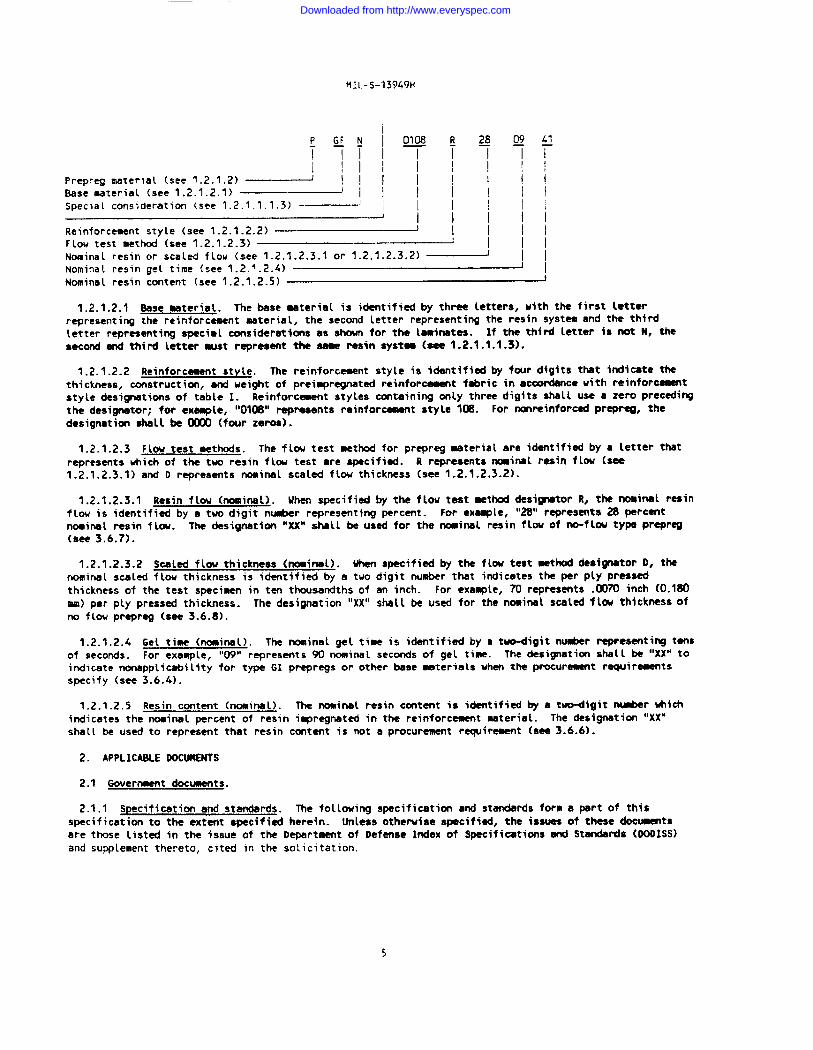
1.2.1.2 Prer2ra9 (reinforced and nonreinforced). The type designation for prepreg shall be in thefollowing form, end as specified (see 3.1 and 6.2). Prepreg aaterial is distinguished from laminate by theletter “P”, designating the construction as a resin preimpregnated reinforcement, folloved by the base
aaterial designator. The reinforce~t, noainal resin flou, noninel scaled flov thickness, noainal geltime, ❑nd nominal resin content are process parameters norually dictated by the printed wiringmanufacturing process. Unless design constraints dictate, these va[ues shall not be inc(uded on the misterdrawings, but shall only be speclfled and used in procur~t spacificatmts by the printed wiri~ boardmanufacturer. h asterisk shall be used to replace each digit on tlw aaster drawing.
L
Downloaded from http://www.everyspec.com
HIL-S-13%9H
yy~olAJ8;y Qf’~
~ ~1Ill I 1 I
Prepreg material (see 1.2.1.2) ~ !~~l!li!Base aeterial (see 1.2.1.2.1) ~ I I I IISpecial consideration (see 1.2.1.1.1.3) --- i II
I I I (i)Reinforcement style (see 1.2.1.2.2) ~ 11~~Flow test method (see 1.2.1.2.3)Noainal resin or scaled flow (see 1.2.1 .2.3.1 or 1.2.1.2.3.2) ~ IINominat resin geL time (see 1.2.1.2.4) — INominal resin content (see 1.2.1.2.5) J
1.2.1 .2.1 8ese material. The base material is identified by three Letters, uith the first letterrepresenting the reinforcement aaterial, the second letter representing the resin systes and the thirdLetter representing special considerations as shown for the Lmminetes. If the third letter is not N, thesecond and third letter nust represent ttsa aaaa resin aystee(sea1.2.1.1.1.3).
1.2.1 .2.2 Reinforceeant style. The reinforcasant style is idantiflad by four dtgits that indicate thethickness, construction, ad weight of preiepregnetad reinforcement fabric in accordance with reinforceasntstyle designations of table 1. Reinforcement styles containing only three digits shalt use a zero precdingt~ desjgnetor; f~ ex~le, ltol~g’ qs~nts reinfor~t style 108. For -minforc~ PraPW/ the
designation shall be OWO (four zeros).
1.2.1 .2.3 Flow test methods. The flow test mthod for preprag material are identified by a letter thatrepresents uhich of the two resin flow test ●re specified. R represents noainel resin flou (see1.2.1.2.3.1) and D represents nominal scaled flow thickness (see 1.2.1.2.3.2).
1.2.1 .2.3.1 Resin flow (nominal). When specified by the flow test eathd designator R, the nominal resinflow is identified by a two digit n-r representing percmt. For enasple, “28” rSPeSS!WS ~ wrc~tnoainal resin flow. lha designation “XX” shell beusad for thertminel resin flouof no-flwtypa preprag(S@? 3.6.7).
1.2.1 .2.3.2 Scaled flow thickness (nosinel). Wan specified by the flow teat eethod deaignetor D, thenominal scaled flou thickness is identified by a two digit number that indicates the per ply pressedthickness of the test spacinen in ten thousandths of an inch. For ●xample, 70 represents .0070 inch (0.180W) per ply pressed thickness. The designation “XX” sheLl be used for the nosinel scaled flou thickness ofno flou pr-qrag (see 3.6.8).
1.2.1 .2.4 Get time (nominal). The nominal gel time is identified by a ttiigit nu&ar representing tensof seconds. For exaxpte, “09” represents 90 nominal seconds of gel time. The designation shatl be “XX” toindicate nonapplicebility for type GI prapregs or other base materials when the procuramsnt raquiraeentsspecify (see 3.6.4).
1.2.1 .2,5 Resin content (nominal). The nominal resin contsmt is identified by a tvo-digit number vhichindicates the nominal percent of resin impregnated in the reinforcassent aaterial. The designation “XX”shall be used to represent that resin content is not a procurement requirement (see 3.6.6).
2. APPLICABLE DOCMENTS
2.1 Government documents.
2.1.1 Specification and standards. The following specification and standards form a pert of thisspecification to the extant specified herein. ihsless otherviae specified, the issues of these documantaare those listed in the issue of the Deperteant of Defense Index of Specifications end Standards (OODISS)and supplement thereto, cited in the solicitation.
5
Downloaded from http://www.everyspec.com

MIL-S-13949H
sPELIF 1LATION
MILITARY
MIL-F-~L256 - Flux, So(der?ng, Liquid (Rosin -se)
SIANDARDS
HILITARY
HIL-STD-13G - identification Marking of US Nilitary Property.HXL-STD-202 - Test Methods for E(?ctronic and Electrical Cc%wponant Parts.FIIL-STD-45662 - Calibration Systems Requirements.
(See s~lament 1 for list of associated specifications. )
2.1.2 Other Government documents, drawings, and publications. l%a follwing other Government documents,drawings, and pubticmtions form e pert of this doument to the extant epeci?isd herein. Unless otharuimaspecified, the issues ●re those cited in the solicitation.
SD-6 - Provisions 6overning Qualification.
(Unless otharvise indicated, copiasof federal and ailitary specifications, standards, and hmdbooks ●reavailable from the Standardization Document Order Desk, Suilding 4D, 700 Robins Avmnue, Philadelphia, PA19’TII-5094. )
Nandbook N4/N8 - Commercial and Government Entity (CAGE).
(Application for copies shoutd be addressed to Oefense Logistics Services Center, ATTN: OLSC-JBOA,Fedmral Canter, 74 U. Umshingta, Battle Creak, tll 49X7 -3084.)
2.2 I@n-6overnment publications. W following documents form a part of this specification to the extentspecified herein. Unless othervise specified, the issues of the docmta vhich am 000 adoptedshall bethose listed in the issue of the DODISS cited in the solicitation. Unless otherwise specified, the i ssussof documents not listed in the DODISS shall be the iSSUS of the non-Government documents which is currant onthe date of the solicitation.
AMERICAN SOCIETY FOR TESTING AND MATERIALS
0150-74 - AC Loss Characteristics and Dielectric Constant (Permittivity) of Solid ElectricalInsulating Materials.
(Applicatim for copies should be addressad to the American Society for Testing and Materials, 1916 RaceStreet, Philadelphia, PA 19103. )
THE INSTITUTE FOR INTERCWNECTING AND PACKAGING ELECTRONIC CIRCUITS (I PC)
IPC-T-50 - Terms and Definitions.IPC-EG-140 - specification for Finishd Fabric Uoven from “E” Glass for Printed Bosrds.IPC-A-142 - Specification for Finished Fabric Uoven from Aramid for Printd Wards.IPC-HF-150 - ?latmt Foi[ for Printed Uiring Applications.IPC-TM-650 - Test MmthodsManual.IPC-S4304 - Soldermbi Lity Test ?h?thods for Printed Uiring Boards.
(Application for copies should be addressed to the Institute for Intarconnacting and PackagingElectronics Circuits, 7380 North L$nooLn Ave, Lincolnwod, IL ~.)
6
Downloaded from http://www.everyspec.com

MI L- S-13949H
(hor+overrnsent standards and otner publ 1 cations a~e nomel Ly awal Labk f ron the organl zaI ions thatprepare or distribute the documents. These documents also may be available in or through libraries orother informational services. )
2.3 Order of wecedence. In the ●vent of .s conflict betveen the text of this specification and thereferences cited herein (except for associated detai 1 specifications, specification sheets or MSstandards), the text of this specification shall take precedence. Mothing in this specification, houever,shall supersede applicable laws and regulations unless a specific exenption has been obtained.
3. REQUIREMENTS
3.1 ~cification sheets. The individual product requirements shall be as specified herein and inaccordance with the applicable specification sheata. Where there ia no apacfficathn sheet available, theindividual requirements shall be as specified in complementary docuaents such as government drawings orordering date sheets (see 6.2). In the event of any conflict betveen requirements of this specification andthe specification sheets, or complementary document, the Latter sha(l govern.
3.2 Qualification. I_aainate and prepreg furniahai under this specification shall be pruiucta Aich arequalified for tisting on the ~L%ablequmlified products tist (W%) @ the time set fcu opanhg of bide(SSe 6.3).
3.2.1 Certificate of conforamnce. All lots Leaving the aanufecturera plmt for any reason shalt beac~ied by a cartificata of conformance. This certificateof conformance shall include but isnotlimitadto the following:
a. Original signature of the coapany official signing the certificate of conformance.
b. The coapanyofficial’s title.
c. Date of original aignmture.
d. The full military specification *r (with revision level and amandamt) and the associated●ilitary specification sheet number (with revision leveL).
e. lhe full military type designation (proper government designation).
f. The complete qualificatiwt reference number (QRN) as aasignad by the qualifying activity.
Each manufacturer shall aaintain e listing of c~ny personnel authorized to sign the certificate ofumforrnoeon behalf of the prioary otfictal md have it ●vailable f@r govarnDM t Fw$au p request.
3.2.2 Authorization to conduct qualification testinq r~uirments. In addition to the requirementsspecified “in SD-6, avery coaparsy requesting authorization @o conduct qualification testing shall insure thatthe foil-ing it- are m file within the qualifying activity:
a. Revision end amendments (if any) of military specification in question.
b. Date of company copy of SD-6 with cc+tfirmation that ell test reports will be prepared in accordancewith SD-6. “ ‘-
c. Date and ravision of NIL-STD-4%62.
d. List of authorized distributors (?IIL-S-13%9 on(y).
(1) Distributor’s revisiom and eeendmsnt (if applicable) of d
(2) Date of distributor’s SD-6.
(3) Date of distributor’s MIL-STD-45662.
ftary spee ficathn.
e. Representative copy of certificate of conformance to be used or in use.
7
Downloaded from http://www.everyspec.com

MI L-S-13949H
f. DESC form 36 {test equipment list).
g. DESC Form 695 (cross reference to MIL-STDA5662).
h. 9uallty ●scurance manual cmtaining the follwlng:
(1) lnc Luding o~anizationat chart.
(2) Including process flw diagram.
(3) Internal audits in accordance with SD-6.
i. CAGE (Contractor and Government Entity) 4 (when applicable).
1. Nine digit zip code (USA only).
k. Naae of current qualifying activity aanager.
1. Rti for a~l test parsorwd (cartifioation of trainhg inchdiw copies of training reowda).
The qualifying activity wi 11 not provide a RPL listing unless all of these items are current and on filewithin DESC-EQ.
3.2.3 Authorized distributors. Every manufacturer shal 1 be completely responsible for ansuri~ that thefollowing procedures are properly folloued:
a. Each coqany on the QPL shall furnish a list to the qualifying activity of those cowaniesuhich they have authorized to distribute their product. This list shall lnCIUdS as a mlniaua:
(1) Naae and address (including nine digit zip code in the United States of Aaerica).
(2) Tclaphone nuabw and point of contact.
(3) Added value functions performed, if any.
b. The manufacturer shall perform audits of their authorized distributors on a ●iniaua of a 1 yearcycle to asaure c~liance to the r~iremants as outlined herein. Partiwlar ~sis shall beplaced on the following iteas:
(1)
(2)
(3)
(4)
(5)
(6)
(7)
(8)
(9)
A system uhartby tk manufacwrer can ansure that the distributor aeintains traceability andprevents intermixing of comercial and QPL certified praduct.
Record ke+ing (dowaan t control), master f i lea, oertif icate of oonf~ca, ●tc. F8Ci lityprocedures she 11 be in place and objective ●violence that they are being used by distributorpersonnel.
Uritten and signed requirements for handling (M’L aateriels agred to between the manufacturerand distributor.
Calibration of applicable equipaent necessary for storage, measuring or disposition of QPLaaterials.
Product aarking requiraaents.
Wed areas to store discrepant QPL products.
Environmental control areas.
Internal audits by the authorized distributor in place (see SD-6).
DI sposi t ion of custoaer returns.
8
Downloaded from http://www.everyspec.com

IIIL-S-:3Q49H
c. Copies of the first aanurtacturer audit reau{Ts sme~l be sent to bESC 8Long u~th ●ny coroectlueactlorm taken if they uere needed. The qualifying mctivi ty reserves the right to require sore orbetter corrective actions if it is deemed necessary. Subsequent audit resu Lts shall be aeintaindby the manufacturer on file for government inspection for a minimum of 3 caLendar years fr- the(ast ckty of the audit.
d. A. 1 authorized distributors shalt be aonitord by their associated manufacturer and must be tlstedon the manufacturer’s Authorized Distributor List (ADL). This List sheli be maintained by themanufacturer with a current copy on file with the qualifying activity. The List sha 1 L have enorlginel signature by the appropriate aenufacturer’s represents.tlve, of ficia L tlt Le, and the date ofthe signature. Additional Ly, these authorized distributors sha L L be subject to DESC audit withmanufacturer not if i eetion. Shoutd any ~lient authorized distributor be aeintmined on themanufacturer’s AOL, this shaLL be grourds for removal of the manufacturer fros the QPL.
3.2.3.1 Certificate of conformance for authorized distributors. Whenever QPL product Leaves theauthorized distributors faci Lity, the authorized distributor shatl inc Lude their M certificate ofconformance in addttion to a copy of the one supplied froa the origina L manufacturer. The authorizeddi stributor’s certificate of conformance shal 1 inc Lude:
a.
b.
c.
d.
e.
f.
9-
h.
i.
Authorized distributor’s name and addNtSS.
~ end address of their cust-r.
FuLL government designation.
Ful 1 QRN for sash government designet ion.
Quantity and size of panels in the shipment.
Type and complexity of aateriat (e. g., GF, GI, prepreg, doubLe or sing Le sided, etc.).
*r of tots and Lot date codes.
Typas of added value parforaed, if any.
Original signature , of ficiaL titte and date of signature.
Copies of aLt appropriate documentation must be on file at the authorized distributor’s facility forgovernment review for a miniaum of 3 calendar years from the date of original signature certification.
NOTE: Should the manufacturer be remved f roa the OPL, suspended, or placd on “Stop shi~t/stopproduction” for any reason, the authorized distributors shatl a Lao be placed on the same status end wi 11remain that way unt i L the manufacturer’s prob Lem is reso Lved. The manufacturer shal L be responsible fornotifying each of its authorized distributors for changes in their status within 24 hours of their becomingauare of a prob Lem existing and a copy of that notification she LL be foruarded to the qualifying activity.
3.3 Terms and definitions. For the purposes of this specification, the terms and definitions of IPC-T-50and those contained herein and in the associated specification sheet shal L appLy. The Government qualifyingactivity shal L interpret the definitions of 6.4 for use wherever pertinent.
3.3.1 Authorized distributors. For the purposes of this specification, the definition of an authorizeddistributor sha LL be “Anyone authorized by the senufacturer to distribute the manufacturer’s product. ”
3.4 Material. The material shal L be as specifial herein. Nouever, when a definite aateriaL is notspecified, a ~terial shat L be USM which wi 11 enab Le the lamnate or prepreg to seet tha perforaencerequirements of this specification. Acceptance or approva L of any constituent materiat sha Ll not beconstrued as a guaranty of the acceptance of the finished product.
9
Downloaded from http://www.everyspec.com

3.4.:fabrics
t!l L-s-13949d
Relnforent mater iai. UnLeAs ~lt=rdlse +ec~fied Lsee 3.1), construct lo:l of the reir, forccmectshal [ be in accordance with table 1. All other properties of applicable reinforcement fabric shall
be in accordance with 3.6.3. The reinforcement fabric shell be ckanad and treat~ with a finish which willproduce the required performance characteristics of the laminate and prepreg in this s~cification (see6.2r)
3. 4,2 Resin $ysten. The resin syst~ms LI!Wd to prchce lauiir,atf and arepreg under this Speclflcat ionshall be as speclfled in 1.2. 1.1.1.2 or the lndivldua L specification sheet. Tne c~itlen of any lasrlnate
or prepreg represented by the aenufacturer’s designation or type number shall be within the fol LowingLtsritations:
a. The absolute aaount of any coaponent material (resin coq=xition, curing agent, opacifier, fireresistant additive, etc. ) aay be varied within a total aaount of i2.5 percmt by veight of thatf=w=t Wterial.
b. The chemical species of a cotorfng or tinting meteria( may be changed if the color or tint is notsubstantially changed, ●nd if the absolute amount of the coloring or tinting aaterial is not changedby sore than *2.5 percent.
c. There shall be no additions or deletions to the c~sitlon.
The manufacturer’s desi~t ion or typs nuaber sha 11 rmt be i ncLuded on thebe specified and used in ●cquisition documents by the printed wiring bard
3.4.3 c omer foi 1. Copper foil shall be in accordance with IPC-MF-150.weight shall be class I for types C, D, G, H, and J and class II for typestable II, unless otherwise specified (see 6.2).
aaster drawings,manufacturer.
The copper foi 1
but shsll OIlty
toLerance byA, B, K, L, and H as specified in
3.4.4 Reinforced Laminate. The reinforced laminates shal 1 cmsi st of one or sore layers ofreinforcesmnt, preimpregnated with the applicable resin system vhi ch may be overlayed with aetal foi 1 on oneor both sides and bonded together and processed to aeet the requi resents of this specification. Unlessotherwise specified (see 3.1 ), or when double-sided clad laminate is to be used ●s a singLe-sidad Laminate,the doubh-sidad cLad Lasinate sha Ll have ● ninimua base thickness of .W35 inch (0.090 aa), and shal 1 havetwo layers of reinforcement f~ric minima.
3.4.5 Prepreg. Prepreg shal L consist of a layer of reinforcement, impregnated with ● resin systea (ace1.2.1.2.2) and the polymer advanced to a B-stage (seaicured)herein and the specification sheet (see 3.1).
, and shall aaet the requirements specified
3.4.6 Color. Color shal L be as specified by the procuring activity (see 6.2). If the color is notspecified, the Laainate or prspreg shal L be furnished in natura L color. Natura 1 is the color produced bythe natura L, undyed reinforceamt and resin systew used.
10
Downloaded from http://www.everyspec.com

NIL-S-13949P
TABLE 1. Relnforcemenl material construction tharacturistics.
I I j/ I Prepreg selection data IlFabric j Fabric -I range I Style I Thickness I Thread count *3 I12/1 I (inches) ~/ I (UXF per inch)
~~
lG111061.@3121 56 X 56 I
I(glass)l 1070 I .0014 [ 64)X35I g/ I 107 I .0015
1
64)41X35] 1080 I .0020 / 60X47
I 11081.0022 I 60~/x47~l
II 2112 { :W& I 40X39
IG21112 I 4og/x39glI (glass) ~ 2113 I.-1 60x56ls/~:yl.flHOl mx64
I I .0032 / 6ogfx64gf
I I 2125 I .0035 40X39I 1125 I .0039 I 4ogf x39
i I 2116 I .W16 I 60X58
I I 116 I .0038 I 60~/x5BQ/
I 116751.00401 40x32
I I 2119 I .0034 I 60X46
I I 119 .0038 1 54g/x50gf
I I 2165 1:~1 60x52
I [ 1165
1~1[ G3 I 1528 I .0065 ~ 42g/x32gfI (glass)l 7637 [ .(XJ89 44x22l&[76421.a)99 i 42X20
/ 11201 .0040[ 34X34lAll~l:~ 60X60I Araaidl 177 / 70X70I 2/]3080630Ml &2 I 60X60
I I I 34x34I 3511 I .CW I 33 x 33
/I Q fl/1 503 I .0030 I 50X40I Quartzl 525 I .0030 I 50 x 50
i~~/ G.esad on finished goods state in which heat-clean&~1
Extent of qualific&ion rely.
I (not for Derforaance requi resmts )Ueight ~/ I Resin content I Moainat thickness
*5 percent I rarge noainal I ra~e cured S/
I as received I0.56 I 70-80 I .0012 - .00220.73 I 70Z; 80 I .0015 - .00251.05 I I 7/
2.052.102.302.402.432.60
1
50-65 {.0030-.004050-65 I .0030 -.004050-65 1.0030 -.(XI4O50-65 1. OmO-.oo4o50-65 ~.oa50 :.0&50-65 . .
1 ,
6.m [ 35-50 /.0062-.00755.95 I 35;,50 \.0fM2-.w7s7.m I 7}
6.70 i ~1 i ‘~1
1.70 jQ/ [ 50-65 I .00420.80 ~f I 55-70 I .(E20.93 Q/ I 50-65 I .00230.90 ~i J 50-65 1.0020l.w Q/ I 55-70 I.O(MOI.n ~/ 1 55-70 ~ .CKMO
1 ,
3.3ol& I 40-60 1.00502.00 Q/ I 40-60 ~ .0030
1.,q ad finishing have been appiied.
Tolerance is @ percent on fabric ranges GI and S2, toterance is i’10 percent on all other fabricranges.Weight is in ounoes per square yard.These values should not be ued for mqutation of dielectric thickness in board design or layout.Reinforcement material shell be made froa E-glass f i laaent (see IPC-EG-140).General ly not avai Lable for use as preprag.Threads (or yarns) are eultistrand (or plied).Reinforcement material shal 1 be made from araaid fibers (see IPC-A-142).Height tolerance is *IO percent.Reinforcement material shall be made from quartz fibers.
11
Downloaded from http://www.everyspec.com

3.5
Weightdesignator
~QTHH1234567
/ Derived by 14.8.1.2.2.
Dimensions.
NominalweightOzlft: .
0.7460.2630.3500.50.75I.m2.003.004.005.006.(KI7.00
ji ght test
tli L- S-1394YH
TABLE 11. COW? r th~ckness and tolerance.
IHeight tolerance I Nominal thicknessby percent t II
~I CLesS 11 I inches (microns)———...-._-_
.mo2
.mo4
.0005
.0007
.ano
.m14
.0028
.0042
.m%
.0070
.0084
.0098
(5.0)(9.0)
(12.0)(17.5)(2s.0)(35.0)(m.o)
(105.0)(140.0)(175.0)(210.0)(265 . O)
}Thickness tolerance I(approximately 10 I
Iinche: (mic-oqs~ (.._———
I
/!
. mO07 (1.75) I
.Ooofo (2.5)
.oOo14 (3.5) 1
.W02EI (7.0) I
.00042 (10.5)
.00056 (14.0) /
.00070 (17.5).mo84 (21 .0) I.00098 (24.5)
I 1 I Isathod2.2.12 of IPC-TW650 or by microsection in ac~rdance with
3.5.1 Luigth end width.
3.5.1.1 Lasqth anduidth of reinforced {~inate sheets, Panels, andssrepreg sheets. Unless otheruisespecified (see 6.2), the manufacturers’ standard sizes shall be accept~la. Standard size laminetas frauhich speciaans hava bacn out for tests required by this specification shall be acoaptoble, unlessparticular diamsims are specified (~ 6.2). The permissible variatims from the specified Length orwidth shall be as Spacifiad in tabLe 11X. Mjaoust edges shall be perpendicular within .003 inch (0.08 M)per inch for laminate and .005 inch (0.13 aa) par inch for prepreg.
3.5.1.2 Lano th and width of continuous 1ength reinforced laaimtes. Unless otherwise specified (sea6.2), the aanuf ●ctur.rs’ swndard ●i me shat L be ac_Le. The tolerance for length and width of standardsizes wil L be *.25 ind (6.4 m) per 12 inches of length or width.
3.5.1.3 Uidth of prepraq rolls. Unless otherwise specified (see 6.2), rol Ls sha LL be supp Lied in themanufacturers’ standard widths +1 .WO, -.5LKI Inch (+25 .40, -12.70 d ( inside of se Lvedge).
TABLE 111. Peraiasible variation in tam th or uidt
I I Permissible variation in Length or width
I (*inch)I Rateria[ ~ Pane 1 size
I Lass than I 12t024 ; ~end
I \ 12 inches I inches
i laminates j .031(0 .79 M) j .063(1 .60 dj. m(3.18 SIW
[ Prepreg 1.063(1.61 mm) 1.125(3.18 mm)l.188(4.78 WI
AL 1 sheetsizes
0.0, -0.0
u/A
12
Downloaded from http://www.everyspec.com

HIL-S-13949H
TABLE IV. Thlcknessi and tolerances for Laelnates. II
I Nominal thickness ~ Class 1I
! of laminates I ( reinforced)I without cladding II (Inches)
I II .Ooloto .LX)45 I *(X)IOI .oo46to.a)65 I MIO15I .00Mto .0120 [ ioo20j .0121 to .M99 I s0025[.0200 to .0309 ~ Ml&l[ .C1310 to .CM09I .0410 to .0659 [ *W75J .0660 to .1009 / *mmI ,Iolo to .1409 ( *0120I .1410 to .2500 i *0220
Class 2‘reinforced)
-7KIOloiaY15*0020
@050:0070
siM20
Class 3 ~/reinforced)
m?*ool oHIOls
*0040N1050
C lass 4(for GR,GX, and GY)
*alo75 ~/*m oas
*aJ30@s
Iclass 5 ~/ I
( relnf~
.0005
.mo?
.Cmo
.0075
.0020
.W30
.W30
.0040
.(Y350
.W
—1.Ced)
-J.Ocrlo 1.0012 I.Ools I.0020 I.0025 ].0035 I.0035.0045 I.0055.0W5 I
—i
1/ Toleranoa value i a daterainad by the nominal baas thickness (less cladding). Tolermnce isapplied over the base plus cLa&ling with no additional toLerance for cladding thickness●llowed. Tolerance of class 5 aaterials is applied to the base thickness (see figure 1).
& k tighter toterancea ere evai LabLe only through product selectionm aoataetarialtypes .
~/ For = base material types, Laeinates belou certain base thickness ere not covered by thisspacifioation, e.g., types 61, 6X, and 6Y are not coverd under .OIO inch (0.25 n) corethickness and core thickness under .~5 inch (O. 090 am) are not currently covered for MYdouble sided laminate.
3.6 Preoraq characteristics. Uhen testad for properties in 3.6.1 through 3.6.10, the raqui~ts shallbe listed as specified in table I and the individual specification sheet for preprag. When teats areperf omed by the procuring activity, prepreg should be proper lY stored (see 3.6.1) and should & tested essoon es possible after receipt (rmt to exceed 10 days).
3.6.1 Shelf life. Unless otherwise specified, prepreg supplied shall be capable of meting therequirements specified herein for not Less than 6 months after recaipt of shipment when stored at a saxiaustemperature of 4.5”( (40° F) and not less than 3 -ths after receipt of shipment utsen stored at a reletivehumdity batwaem 30 end 50 par-t and a aaxiaua teaparatu~ of 21.1°C (70”F) (sea 6.9).
3.6.2 Presence of dicwxlirnide crystals. Wan tested in accordance with 4.8.2.1, there shell be nopresence of crystalline ewwtuma in the fom of clusters or flakes. Individual, scattered “dicy” crystalsstill not be cause for rejacticm.
3.6.3 uOven rein forcmt, thread count, and fabric weitit. Uhan testad in accordance with 4.8.2.2, therequirmts for thread ommt, and ftiic wei#tt shall be *S spacifid (see table 1) ●ti cannot be used todetermine properties for PTFE based laminates (grede GP, GR, GX, GT or GY), or any aramid reinforcedlaminate or prepreg.
3.6.4 Gel tiaa. then tested in accordance with 4.6.2.3, the gal time shall Confom to the Ixminal tiaaas specified (aaa 1.2.1.2.4, 6.2, and 6.71).
3.6.5 votatfk! content. Wan tested in eo oordance with 4.8.2.4, the voletf Le content shall not begraater than the property values shows in the spacif i cat ion sheet for praprag (see 3.1).
3.6.6 Resin content.
3.6.6.1 Resin content (by treated ueight). Wan testad in accordance with 4.8.2.5.1, the nominalpercentage (see 1.2,1 .2.5) of resin content shall be within the range indicated In table 1 for the specif ledreinforcement sty le, and the actual resin percent shall not vary more than 5 percent from the nominal (see6.2).
13
Downloaded from http://www.everyspec.com

3.6. b.2 iie.s)lI contenl (t,y hur(. ou:) e*c,ep; GP GR, &x, GT, GY, AF, Al, or El:. Uhen tested 1P ac:ordm:ewith 4.8.2.5.2, the nominal percentage (sac 1.2.1.2.5) of resin content shall be within the range indicatdin table I for the specified reinforcement style, and the actua( resin percent shall not vary more than 5percent from the nominal (see 6.2).
3.6.7 Resin flow. UhM tested in accordance with 4.8.2.6.1, the percentage of resin flow shalt not varymore than *5 percent from the nominal percentage (see 6.2).
3.6.7.1 Resin flou/”no-ftcw” resin. Uhen tested In accordance with 4.8.2.6.1.1, the diaaeter of theclearance hole shall not be reduced less than .010 inch (0.25 ❑M) nor more than .060 inch (1 .52 ●m). Thisuatue shalt represent 2 percent resin flow.
3.6.8 Scaled flow thicknass. Uhen tested in accordance with 4.8.2.6.2, the nominal prepreg thickness perply sh.sl 1 be within the r- of the s~cif id glass reinforcaaent styte listed in tebLe I end the tolerancespecified on the pmcureasnt document by the printad wiring board mmufacturer.
3.6.9 Electrical strength. Uhen tested in accordance with 4.8.2.7.1, the ●inimum electrical strength(perpendicular to lnirntions, short time) shall be 8s specified (see 3.1).
3.6.10 Peraittivity and Loss tangent. Uhen prepared in accordance with 4.8.2 .?.2, and tested inaccordance with 4.8.3.13, mexiwa permittiwity and Loss tangmt at the specified test frequency (see 3.1)shal L be as specified (aae 3.1).
3.6.11 Cheaical reaistmce (K S= ified, see 6.2). W tested inaccmdence with 4.8.2.8, themaximum absorption of methylene chloride shall be as specified (see 6.2).
3.6.12 FLauebi Lity (uhen xcj fied. a? 3,1~. Uhen tested in accordance uith 4.8.2.9, the nmxiaum burnLength total end individual bum times s~ll be as spec~fied (see 3.1).
3.7 Characteristics of Laminates,
3.7.1 Hetal clmd laminate characteristics.
3.7.1.1 Surface finish of metel-clad surfacea.
3.7.1 .1.1 Pits and dents. Grade of pits and dents shall be es specified (see 1.2.1 and 6.2).Examination and deterainmtion of point count for pitcanddemts ehaLl be in ●ccordance with4.8.3.1.Requirements for pits and dents do not apply to copper that has bean treated on both sides.
a. Grade A. The total point count shml( be less then 30 for any 12-by-12 inch area (eee note).
b. Grade B. The total point count shal L be less than 6 for any 12-by-12 inch area. There shall be nopits or dents with tha longest diaensi~ greater than .015 inch (0.38 m). Pits with the Ltmgeatdimension greater then .005 inch (0.13 mm) shall not exceed three in any sqwre toot (pmels onty)(see note).
c. Grade C. The total point count sha Ll be less than 100 for any 12-by-12 inch area (see note).
d. Grade 0. The total point count ahalL be less than 18 for my 12-by-12 inch area (sss note).
NOTE : The producibility of printed wiring boards ~ using Leeinates with dagreee of pita end dents iasignificantly influenced by the meta L pattern and the process mad by the ~acturer to prodce theprinted wiring boards. Unless desi~ constraints dictate, this grade shal L mt be included on the resterdrawings, but shal L onlyba ~cified and used in pmcuraamt specifications by the printed wiring boardmanufacturer.
3,7.1 .1.2 Urink Les. There shall be no meta L-cLad wrinkles as seen under norma L or corrected 20/20vision.
14
Downloaded from http://www.everyspec.com

P!lL- S-139L”H
3.7.1 .1.3 Scratches. When tested In accordance wtth 4.6.3.2, scratches on either panets or sneets lessthan 5 percent of the maiml foil thickness in depth and Less then 4 inches Long are permitted. Scratchesthat are greater than 20 percent of the nominal foil thickness in depth are not permitted on ●ither panelsor sheets. Scratches betueen the tvo ranges previwsly indicat~ (5 to 20 percent) on ●ither panels orsheets shall be Limited to no more than 5 scratches per square foot +nside the working area of ●ither panelsor sheets. W working area is considered the area inside a 1 inch border of panels or sheets.
3.7,1.1 .& Solclerabi lity. Uhen laminates are tested as specified in 4.8.3.3, the metal -ctad surfacesshal 1 not exhibit nonwetting, nor greater than 5 percent dewetting.
3.7.1 .1.5 Metal surfaces processebility. bthen specimens are etched as specified in 4.7.1.3.2, the metalcladding shall be readi~) reizouab~e, as determined by examination o f laminate pane~s (see 4.8.3.4) to beused for other testing (see 4.8.3.6.2). Metal cladding surface discolorations or protective coating whichAversely affects printed wi ring board fabrication ehal L be redi Ly reeovable by standard cheaical cleeningprocesses.
For etched test specimens the metat cladding surface sha~ 1 be readily removable when etched in accordancewith 4-7.1.3.2. There shel 1 be not BOre tkn me pieca of residual metal per 5 quera feet of surfaceexamined and this piece may not have an area greater than that of a circle .CD5 (0.13 m) (.000018 squareinch) in diemeter. The etched test specimens shell meet the rquiraments specified in 3.7.1.2.
3.7.1.2 @pearmce of base material after metal reaoval. FoLLowing eetal remove L as specified in4.7.1.3.2, the base aeterial sIML1 be inspected in ●ccordance with 4.8.3.4.
3.7.1 .2.1 Surface and subsurface ime rfect ions. Surface end subwrface imperfections (such as weavetexture, resin starvation, scorching, voids, opaque foreign inclusions, foreign -tter, inclusions) shel Lbe accaptabte providing:
a. The reinforcement fiber is not cut or exposed.
b. The imperfections are nonconductive.
c. The imperf ●ct ions do not propagate as a resu~t of therms 1 stress test.
d. The voids are no greater than .CQ3 inch (0.08 m) in the Longest dimsnsims. Surfoce voids shallnot occur in void clusters with more than three adjacent voids in an . 12S-inch (3.18 am) diameterwide circle.
●✎ The foreign inclusions are translucent.
f. The opaque foreign inclusions are no greater than .020 inch (0.51 mm) in the Longest dieension andoccur no more frequently than two spots per 144 square inch.
3.7.2 80U and twist. This requirement does not apply to double-sided laminate with unqua L cladding of 3oz/ft ? ( .0042 inch (0.110 mm)) or greater betwean the two sides, or singLe sided aetal clad leminete that iscWI with 4 oz/ftl (.0056 inch (0.140 m)) or greater on a single side (see table V). Single sided metalclad Laminates shal L not be aachanically deforoed or bent to reduce or rae bw and twist.
3.7.2.1 Sheets and pane 1s with twth dimensions 12 inches or greater. when eeesurad as specified in4.8.3.5.1, the bow and twist of watal clad leainetes shal L not exceed that shovn in table V. Percentage ofbow is given in teras of the lateral dieansions ( Length end width) of the tested apacimsn, ●nd percentage oftwist is given in terms of the diagonal dimension.
3.7.2.2 Panels with one or both dimensions under 12 inches. I/MI measured as specified in 4.8.3.5.2, thebow and twist of mstal clad Laminates shal 1 not exceed that shown in table V.
3.7.3 Therma L stress. Uhen specimens are tested as specified in 4.8.3.6, neither the etched surface northe originetly unclad surface, if ●pplicable, shell show charring, wrface cont~ination, Loss of surfaceresin, softening, delamination, crazing, inter laminar blistering, or weave exposure. In addition,metal-clad specimns shall show no blistering or delamination of the metal foi 1.
15
Downloaded from http://www.everyspec.com

PIL-’; -1!?L?II
Fleas les shat L ue I>C~ gl ea; e: Ltta(l .J2J !Dci”, :2.51 mm ..I: ,r., une c? -C: CII C-. and trerc :w! : :tr PC w~$ ‘t~al’.two measles per each side of 2 x 2 specimen. NO laminates voids shalt be greater than .003 inch (0.08 mm)
3.7 6 Pee( strenqth. Uhen specimens are tested as specified in 6.8.3.7, 4.8.3.7.1, 4.8.3.7.2, or4.8.3.7.3, the average peel strength for each cLad side of ●ach specimen shal~ meet or exceed the m~nimumvalue specified (see 3.1). No indiv~dual va~ue of the values included In the calculation of the averageVW: streng:h shall. b more than 1-1/? ownds per Jo.:t (ess than ?t?e fpeclfled m+rimm value.
3.7.5 Volume res~stivlty and surtace resls.tlvlty. Uhen speclfnecs are ●xposed to the environmentalconditions and tested as specified In 4.8.3.8, the min~mum volume ~es?stlvity and surface resist lvity foreach specimen shal: be as specified (see 3.1).
TA8L.E V. Permissible bov and twist, all foi L weiohts. ~f
I Thickness I Test specimen I maximum variation (percent) for Class C laminate II inches ~ max dimension I Sinqle sided ! Double sidedI (see table IV) I (inches) ! All types 2/ I All Other types I TYpes GP, GR, GT, W GYI
I I I I I II .02~to .0309 I 8or less j 2.0 j 1.0 ! I
8 to 12 2.0 1.5 iI .0310to .0659 I 8or less I 1.S [ 0.5 I 3.0
I 8 to 12 1.5 1.0 3.0I .0660 and over I 12 or less I 1.0 I 0.5 I ?.5 /
~/ Unless otherwise specified (see 3.1).~/ Not applicable for types GP, GR, GT, GX, and GY.
3.7.6 Dimensional stability. When specimens are tested as specified in 4.8.3.9, the average of theabsolute value of change in each direction shalt meet the mmKiaua value specified (sss 3.1). IMeaaothervise specified, class A shal~ be in effect (see 3.1 and 6.2).
3.7.7 Uater absorption. When spec?mens are tested as specified in 4.8.3,10, the average maximum waterabsorption sha LL be as specified (see 3.1).
3.7.8 Dielectric breakdown (pmral Lel to laminations). Uhen specimens are tested as specified in4.8.3.11, the dielectric breakdoun shal L be as specified (see 3.1).
3.7.9 Electrical strenqth (perpendicular to Laminations). When specimens are tested in accordance with4.8.3.12, the average minimum electrical strength (perpendicular to Laminations) shs IL be as specified (see3.1).
3.7.10 Permittivity and loss tanqent. Uhen tested in &ccordance with 4.8.3.13, the permittivlty and losstangent shall be as specified (see 3.1).
3.7.11 Q (resonance) (uhen specified, see 3.1). Uhen specimens are tested as specified in 4.8.3.14, theaverage ●inimum 9 dtall be as specifid (see 3.1).
3.7.12 Flexural strenath. Uhen specimens are tested as specified in 4.8.3.15, the average minimumfLexural strength aha~l be as apeclfiad (see 3.1).
3.7. !2.1 Flexural str asmath at ●levated tempe rature (vtm specified, see 3.1). Uheri specimens are testedas specified in 4.8.3.15.1, the average minimum flexural strength at elevated temperature shell be asspecified (see 3.1).
3.7.13 Arc resistance. When speclmans are tested as specified in 4.8.3.16, the average ●~nimum arcresistance sha Ll be as specified (see 3.1).
3.7.14 Flammability (vhen specified, sae 3.11. Uhen specimens are tested as specifi~ in 4.8.3.17, themaximum burn Length, tota L and individual burn times sha(l be as specified (see 3.1).
3.7.15 Funqus resistance. Uhen specimens are tested as specified In 4.8.3.18, the base matt?ria[ sha(~resist the growth of fungi and sha(~ have a visual rating cf “O”.
Downloaded from http://www.everyspec.com

HIL-S-13949H
3.7.16 Chem~ca: resistance (tihen Speclf led, see 3.1 and b. Z). Uhen tesled in accordance ti:th ~.d.~.’ts,the maximum absorption of methytene ch~oride she~l be as specified (see 3.1 and 6.2).
3.7.17 Pressure vessel thermal stress (when specified, see 6.2) . Uhen specimens are tested as specifiedin 4.8.3.20, the performance rating shall meet the va~ue specified (see 6.2).
3.7,18 Glass transition temernture (Tq) (Men $p~clfled, see 3.1 and 6.2). Uhen spec~mens are tested asspecified in 4.8.3.21, the Tg shall meet the values specified (see 3.1 and 6.2).
3.7.19 Averaqe coefficient of thermal expansion (CTE) (when specified, see 3.1 and 6.2). When specinensare tested as specified in 4.8.3.22, the CTE shall meet the values specified (see 3.1 and 6.2).
3.8 Narkinq. Laminate and prepreg sheets shal~ have a label attached to the package. Preprq rollsshall have a label securely attached to the compatible protective bag enveloping the roll and the two labels(one each) attached to the inside surface of the care aandrel at both ends. All Lebats shatl be inaccordance uith MIL-STD-130, with the military specification -r, type designation, the manufacturer’sswrce code (CAGE), and the lot nunber (see 1.2.1.1 or 1.2.1.2). In addition, prepreg Labels shalt bemarked with the date of i~regnation. All labels shell be of such a character as to reaain securelyaffixed and legible tiring normal handling.
Each full-size laainete sheet aha~t be aerked. Location of aarking and type of marking shall be asspecified in the drawing data. The ●xact information in the aarking shall be sufficient to aaintaintraceability within the printed wiring board manufacturer’s facilities.
Cut-to-size panels of laminate shell be marked as specified in the ordering data. Uhen eppLiceble, the needfor marking, end Location of the marking, the information presant~ in the marking, and the type of markingshe LL be specified. Types of acceptable markings are:
A- Ink of noncorrosive types that shall remain legibLe during noraaL handling, but readity reaovabLeprior to fabrication uhi ch wi 1 L not af feet the physica L electrical properties of the laminate.
8- LabeLs that cart be of a character that remain secureLy affixed and Legible during normal handling.
c- A meta L emboss ing stamp.
3.9 UorkmenshiQ. Printed wiring board matarial shall be manufactured and processed in accordance withthe rqui raaents of this specification. All printed wiring Lmard materia L shal L be uniform in qua Lity andfree of defects which aay affect fabrication, Life or serviceabi Lity, in excess of those aL lowed in thisspecification. The laminates sha Ll be free of wrinkles or erackc. The prepreg sheets shal 1 be free fromtears and the prepreg rdLs sheLL be % percent free froa tears. UnLess otheruise specified, there shaLlbe two spLi ces (no cutouts) aL Lowed for prepreg rol Ls per every 100 yards of prepreg and the spLice shel Lbe clear(y marked.
3.10 Letters of interpretation and poLicy. Letters of interpretation end poLicy shat L be approved inwriting by the preparing activity. ALL letters of interpretation end Pot icy applicable to HIL-S-13949 andits associated specification sheets written prior to the current date of that particular document are nuLland void. ALL subsequent Letters of interpretation and poLicy Letters are va Lid onLy unt i L the nextdocuaent action.
4. QUALI W ASSURANCE PROVISIONS
4.1 Respon sibi Lity for inspection and facilities audit. The Manufacturer is responsible for theperformance of all inspactial raquiraaents as specified herein, and any additional inspactia requirenantaof the specification sheet (see 3.1), or the associated acquisition docwmt. TW mwfacturer nay use hisown or any other suitable facilities which has been approved and certified (granted Laboratory suitabi Lity)by the qualifying activity for the performance of the tests or inspectitm requirements specified herein.The Government or the acqui ring activity or his LOWL government inspector reserves the right to witness orperform any of the in~ctions set forth herein or in the specification sheet or acquisition docuaent a n d toaudit the data resu Lting f mm the manufacturer Is performance of these inspections to assure suppLies andservices conform to the prescribed rqui rements.
Audits of an authorized cJi$tr~butor wi L1 be conducted at the discretion of the qualifying activity.
‘1?
Downloaded from http://www.everyspec.com

MI L- S-!396W
4.1.’1 Respons lblllty tor coaptmnce. ALL item shetl aeet 8LL requ~roments oi aectims 3 ●d 5. Theinspection set forth in this specification shell becoae a pert of the aenufacturer’s overall inspectionsysten or quality program. The absence of any inspection rquireaents herein or in the specification sheetshal 1 not relieve the manufacturer of the res~nsibi lity of ensuring that all products or supplies submittedto the Government for ●cceptance comply with al 1 requi resents of the contract. Saapling Inspect Ion, as ~rtof manufacturing operations, is an acceptable prect ice to ascertain confo~ce to requirements, houwer,this does not authorize submission of known defective material, either indicated or actual, nor does itcommit the Government to accept defective material.
4.1.2 Test ~uim t and ins~ction facility or test Laboratory. The manufacturer shel L establish andmaintain test and measuring equipaant and inspection facilities of requird accuracy, que Lity and quantityto permit performance of the required inspections. All teet quipaent shall b listed on a DESC Form 36 oraa rquired by the qualifying ●ctivity. A non-Sovernaent test laboratory for qualification testing, qualityconformance inspection or scr-ing ahal L be required to aaintain its quipaant in proper calibration toassure accuracy of teat results. Records of this calibration shalL be maintained and * evai LtiLe toauthorized Government representative(e) wfwnever requested. The ●stabli shaent end maintenance of acalibration system to control the accuracy of the aeasurtng and test equipmant shel 1 be in accordance withMIL-STD-45662. DESC Form 6% shal 1 be uaad to cross reference ktuean RI L-STD-45662 requi r~ts and ths~ny ’s =libration systee. The qualifying act i vi ty reserves the right to @ate or iaprove/chenga therequired cross reference form. The use of a non-Government lalmratory is for an established perid, and is
subject to a 2-year periodic r-audit by ths Defense Electronic St@ply Center (DESC) Dayton, Ohio.
4.2 Classification of inwactiona. The inspections specified herain are classified as follow:
a. l$eterials inspection (see 4.3).
b. Qualification inspection (sea 4.5).
c. Quality -formsnce inspection (sss 4.6).
4.3 Materials inspec tion. Materials inspection shall consist of certification su~rted by verifyingdata, uhan specified (sea 6.2), that the asterials listed in table VI, used in fabricating the eetaL-cLadLaainetes, are in accordmce with the applicable referenced speci f i cat im or raqui reoents prior to suchfabricating. This verifying data is required for qualification.
TABLE VI. ftaterials ina~ctica.
I lRquiranent I Applicable II Raterial I paragraph I specif i cation I
~~1
I Reinforcement cloth [ 3.4.1 I /lResin I 3.6.2 II Copper foi 1 I 3.4.3 I IPC-PFF-150 IlPigaent or dye ~/ I 3.4.6 I I
II Verification of pigment or dye type, if present.
4.4 Inspection conditions. Unless otherwise specified herein, all inspections shall be perforasd inaccordance with the test conditions specified in the “GENERAL REGUIREHENTS” of HIL-STD-202.
4.5 rNa Lification inspac tion. CIualiiication inspection aheLl be performed at a laboratory acceptable tothe Government (see 6.3) on ~le units prttduced with ~ipaent und procedures normally used inproduct im.
4.5.1 Samle size. Sm@e sheets shal 1 be selected from norme 1 product ion for each asnufacturers’ brandunder a type (and, for prepreg, a ~inal cured thickness) for which qualification is sought. The nuaber ofspecimens required per sheet and their conditioning shall be as specified in 4.7.1. The nueber of speciaens(see table VII) required for the individual test methods shall be cut fro+s the sheets and inspected asspecified (see 4.5.2). The inspections requiring the fu(( sheet shall be performed before the sheet IS cutInto smaller specimens.
18
Downloaded from http://www.everyspec.com

4.5.2 Inspect Ion rouzlne. The sample shalispec i men Is to bs used for more than one test,
MIL-S-l~?4~h
De subjected to the Inspections spac]f ied. bitten znethe order of testing sha LL be as specified in table VII.
4 .5,2.7 Test rermrt format. All test reports subsvtted to the qualifying activity shali be submittedentlre(y In the English language and conform to the lnforsat!on rewired and format shown in the “TESTREP~RT1l ~ectioo of SD-6. The test report shall be verified by the appropriate Government Quality AssuranceRePre:>entatlve or Na~io-siL G+uaL’,fvlr!cj Acti,lty prior TC hauing the orlgiral submitted to the qual:fylrgactivity. Companies in countries without an international Standardization Agreement (lSA) must have aLlgroup C and qua~iflcation testing done within the continental Unitd States at a OESC approwl Independenttesting Laboratory. These companies must have the testing laboratory they are using prepare their portionof the test re~rt in the SD-6 required format and submit the final document back to the company in time forcombination with the group A and B testing summary with aubndtte{ of the entire package to the qualifyingactivity prior to expiration of the grace period. Actual test data shall be mintained in a raadllyaccessible locatiom at the manufacturer’s fsscility for a ainiaua of 3 calender years from the retentismreporting date. The act~l test data smL( be compiled in such a manner that a person inexperienced uithcompany policies and procedures will be able to ●asily understand what information the data is attempting toconvey. All failures will be prominently marked for easy idantfficetion and the corrective actions taken bythe coapany shall be attached to the failed data. Reports arriving at theqtalifying ●ctivity without theproper for=t will be rejected without reviav and steps uill be initiated for possible removal from the *L.
4.5.3 Extent of qualification.
6. S.3.1 Lamneta. Extant of qualification for Laminates ●hatl be in ●ccordmce with table VIII.
4.5.3.2 Prepreg. Extent of qualtficaticm for preprags shell be in accordance with table IX.
4.5.4 Failures. One or more failures shall be cause for refusal to grant qualification approval.Failure criteria for specimens shall be as specified in the applicable aethod paragraph or requirementparagraph.
4.5.5 Retention of flus lification. Retention of qualification iS 00nSldeWd to be an integral part of thequal~fication process and as such all provisions ●stablished in SD-6 shatl apply. To retain qualification,the QPL manufacturer shall forward at 12-month intervals, as established by the qualifying ●ctivity, usingthe format specified in 4.5.2.1, a report containing the following items listed belov:
a. A summary of prtiucts manufactured each aonth.
b. A summary of the resuLts of retention testing in the SD-6 test report foraat.
c. The nwtbar end types of failures experienced ●nd corrective actions.
d. Representative samples (at least 10 radoa samples ~/) of each products final certificate ofconformance, and representative samptes (at least one from each vendor) of the certificate ofconformences from the various vendors with hom the ~pany purchases raw materials and with whomoutside calibration is done.
●. A sumary of the nu~r and types of interna L audits performed at the manufacturing plant ●nd ●teach Authorized Distributor faci Lity.
f. At least 10 random s~les of certificates of conformance from each Authorized Distributor. II
j/ If the maximum number of certificates of conformance signed is Less than 10, then all that have beensigned sha~[ he suhnittec,
19
Downloaded from http://www.everyspec.com

PIIL-s-139L9H
in SOOltlm to the above, the eenufacturer shaLL suoelt an ouora Ll certifiwte of amforma= uhich narrantsthat all aspects of manufacture to this specification and latest amendment have been met and a aeparetecertificate of conformance from each authorized distributor warranting they also have aet SI1[ requiredspecification items. The qualifying activity reserves the right to require any or all parts of theretention data be sent to thee at any tiae, ●ither via written or telephornc ~i~titm uithout priornotice te the capany. lk aswwfacturer sheLl aubeit an updated version of their authorized distributorlist.
Actual test data for groups B and C, shall be supp{iad when rquested by the qualifying activity. It shaltbe aaintainad at the aenufacturer’s foci Lity for govemeant review for 3 cabmdar years f roa the retentiondate assigned by the qualifying activity, _ies having plants both within the continental United Statesand off shors shell estab(fah ona of theircontinental Unitad States plants as a aain one and shall retainccpies of retention data from all off shore plant foci lities for Government reviau. For tompanies havtngonly a selea office in the continantol Wited Statea, the sales office shall aaintain these test records andmay be euditad by the qualifying ●ctivity.
Retention of qualification ●xtanairn shell be as that ●houn on the ~L. For exeaple, if production of GMoccurred duri~ ● ~ting *riod * 99 was not producd, retentia of ~lifi~kn vilL be extashd toGO and requaLif ioetion wi 11 not be necessary as tong as SH production aeets tho raquiraaants of thisparagraph.
Fai lure to subait the report within 60 days after the end of each 12-aonth period eay result in loss ofqualification for tha product. In additim to the periodic aubeiaaion of inspection data, the QPLmanufacturer shall itiiately notify the qualifying activity at any time during the 12-aonth period thatthe inspection data indicatea fai Lure of the qualified product to meet the r~uiraants of thisspecification.
4.5.5.1 Ilodification Qf aua lified DfOdUCtS. No modifications of the composition of any qualified productshall be mde without requalification, ●xcept within the following limitations:
a. The absolute eaount of ●ny coapcmmt mterial (resin coapoaition, curing agent, opacifier, fireresistant additive, etc. ) aay be varied within a totaL umunt of 2.5 percent of that ~t-oriot.
b. The chenical species of a coloring material my be changed if the color is not substantially changed,and if the absolute enount of the coloring saterial is not changed by -e than 2.5 percent.
c. There shall be no additions or deletions to the composition.
The qualif i ad product manufacturer remains reapmsible for cat inuing to meet aL 1 raquireoants of thespecification under which the acxiified product was originally qualified.
4.6 Quality conforamce in soect im. -lies or defects tinted on panels or sheets (or both) defined inall inspection tables shall & necordad end the p-r corrective ●ction shall be initiatad-
4.6.1 Inspection of product for delivery. Inspection of product for det i very shal 1 consist of groups Aand B
4.6.’
a.
b.
c.
nspect ions.
.1 Xnsoecticm lot. h inspection lot ahaLl aaet the following:
Ladnete, group A. An inepecticm lot shall meet the following criteria: The aeterial shall becovered by a single specification sheet, aaaa type daai~tion so far ●s practicable, uui of ferwxifor inspection et one time.
Laainete, group B. An inspection lot for group 8 inspections shell be one press load or 200 sheets,whichever is greater (the 2W sheets aha~l be f roe consecutive prea$ loads).
Prepreg. An inspection lot for prepregs shot 1 be 250 yards or one rol 1 which ever is greater in
accordance with 4.6.1.2.1.2.
20
Downloaded from http://www.everyspec.com

.——.
.—— —.
?lIL-s-13949H-———————— ——.. ——- ———— —— ———— ——— —. — ——
x X%xx%xx %x XXxx
x Xxxx xxx xxx xx Xxxx
-———— ———— ———— ——— ——— ———— ———— ——— ——.— —
x x%x%x x xxx
9.
.—. ———e —.————-————————————— —— —
.
Downloaded from http://www.everyspec.com

.———.
MI L-S-13949H
————— .—— ——— ——— ——— ——— -
xx xxx x xx
.——. ——— —— —— ——— —
\ml
x x% XXxx xx %x
,——————— ———— ———— ———— —-
%
-———— ————— ———— ———— ———.
-———.—— ——————-————— ———
Lv>0
Downloaded from http://www.everyspec.com

TAEILE VIII. Extent of quallf i cation, lamlna~es.
] prQDerty ! Qualified I Extended to iI I I II Base material type I GF* GFN II I GW I GBNI 1 GI* GIN /
I GRN GPN 1“\ I GXN 6TN I\ (NN GTN and 6XN ~
ii Nominal base thickness i Thickest over .020 inch j bun to .020 inch iI lThinnest below .020 inchl Up to .199 inch I[ I I II Metal cladding i DcnMe I Single end uncled I~ I
I I Ii Type of chdding i Any copper I All copper I
II I I II Noein.eL copper foil I 1I weight I Any copper weight ~ All greater copper weights ~
I For exaaple:
I I I ~I I 0.25 oz/ft’ 0.25 ozlftz end greaterI I I i
i 0.5 OzIft’ I 0.5 ozlft2 and greeter iI I I
1.0 Ozlftz 1.0 ozfftl and areater II I I
6redaof pits end dents I 8 A, C, D I
i Class of bou end twist i Any I All i
23
Downloaded from http://www.everyspec.com

fl iL- S- i 394Qti
I I II Property Qua Llfled Extended to
I ti BaBematerlat type PGF* PGEN
I any PGF* , at ~ PGFNany PGl* a~~ PGIN
1I Reinforcement style ] Any ranqe G? Al 1 range GI
I I Any ranqe G2 AL1 ranqe G2 1
I I AnY rafust 63 1 All ranee (33 II i w ramw A All range A II Any range Q I
IAll range 9
II Moalnal resin flov and \
II
~ Melnat scaled f Lou Any All /I II Gal tiae
I IAny All I
I I~ Resin cmtent Any All I
I I II Class of thickness I I I[ tolerance Any All II I I II Fmgus I bmlnates le*s than I Laainates over .020 inch I
.020 inch and rmmreg II I I II Fl~lLity I < .020 inch .020 inch and over I
2 .020 Inch I Preprao
4.6.1.2 GrcuP A in apaction. Group A inspection shalt cmsist of the inspections specified in tabte X.
k.6.1 .2.7 SLiw o~M.
4.6.1 .2.1.1 Laainate. Statistical sa~ling shall be in accordance with table XI. No failures shall beallou~. Ikaauraments -y be perforaad ●t bient conditims.
4.6.7.2.1.2 Prepreq rolls and sheets. One yard at the beginning of each roll and avery 250 linear yardincrement thereafter. For runs less than 250 yards, a s~le sha( L be taken at the beginning and at theend of the roll. If a roll is not divisible by 250, then saeples shall be taken at the beginning, at 250yard increments and at the end. If the prepreg is cut into sheets, the saae rules apply regardless of sheatsize. Samples shall be retained for group B inspections. Exaaples are ●s follows:
a. A 300 yard roll vould require
b. A 500 yard roll would require
c. A 600 yard rol[ would require
three sasples, at the beginning, at 250, and 3CXI
three sa@ples, at the beginning, at 250, and 500
four samples, at the beginning, at 250, 500, and
yard points.
yard points.
600 yard points.
d. A IOOU yard roll would rquire five ~las, at the beginning, at 250, SW, 750, and IMO yardpoints.
4.6.1 .2.2 Defect+. For statistical QLing, if an inspactim Lot is rejected, the cmtractor w screenout the defects and resubait for reinspectim. Such lots shal 1 be separated f roe uninspected lots and shaL (be clear(y identifid as lots that need reinspection. The screenl ng process sha( L not count as thereinspactlon. For 100 percent inspection, defects shatl be removed from the Lot and shall not be shippedwith the lot.
4.6.1.3 Group B inspection. Group B inspection shal( consist of the inspections specified In tabie X11No fal Lures shall be allowed.
24
Downloaded from http://www.everyspec.com

H:!. -S-13?4W
1
iiv
———______ —_—— ———
&0*
25
Downloaded from http://www.everyspec.com

MIL-S-13%9H
———————————— ———— ———————————— ———————————. —
1!a L
..-L ; .:
“ h$i % xxx x%x% xx
:
x
w 0.—————————— ———. ———— ————————— ———— ————;J –;
:% g’ \(-UI
~ iq
% x%x %x% %Xx% x%x%
—— ————————— ————————————— ————— ————————
48 Xxxx xxx x&&——— .—— —————————————————————= ——— ——————
Gl” 1 [
——. —
8.-
——— -—————— ———— —————
I
:1 kl
26
Downloaded from http://www.everyspec.com

tlIL-S-13949H
4.6.1 .3.1 Saupllng plan.
4.6.1 .3.1.1 Laminate. The sa~le sha Ll consist of two randoaly selectd sheets (as pressed) ●inimum.
4.6.1 .3.1.2 Preprq ro~ls and sheets. The samples pulled for group A inspection shall be used for groupB inspection.
4.6.1 .3.2 Rejected lots. If an inspection lot of prepreg is rejected, the previous continuous lot (rolt)shak~ also be rejectd, the contractor may screen out the defects and resubmit for reinspection. If an
inspection tot of laminates is rejected, the contractor may screen out defects and resubait forreinspection. Such lots shall be separate from new Lots and shell be clearly identified as rejected lots.
4.6.1 .3.3 Disposition of sa8pLe units. Sample sheets which have beem puLLed for group B inspection ●ndhave pussed gtwp B inspection shall be held for group C inspection.
4.6.2 Periodic inspection. Periodic inspection shal 1 consist of group C. Except vhere the results ofthese inspections show nonconptiance with the applicable raquireaants (see 4.6.2.1 .4), de Livery of productswhich have passed groups A and B shal L not be deLayed pending the results of these periodic inspectiats.Resu Lts of group C shal 1 appty for all lots shipped untl 1 the next periodic inspection (group C).
4.6.2.1 Gr oup C inspection. Group C inspection shall consist of the inspections specified in table XIII.Group C inspection shal 1 be made on sawle sheets selected froa inspection lots which have passed the groupsA and B inspection. One month Ly group C arxl one quarterly group C every 12 aonths shall be parforaad at ●
DESC approved Laboratory.
4.6.2.1.1 Samolinia D lan. SaapLe sheets shsl L be selected froa the first lot and thence froa eachsampling period’s production of sheets covered by a single specification sheet and thickness range inaccordance with table XIV or tab Le XV. Sample sheets selected sha L 1 be representative of production asapplicable to sheet thickness and metal cladding.
4.6.2.1.2 Defects. If the number of defects exceed the number al Lowed in table XIV or table XV, thesamle shall be considered to have fai Led.
4.6.2.1.3 Disrmsition of sample units. Unless otherwise specified (see 6.2), aaapLe sheets froa whichspaciaens have been cut and have passed aL 1 the group C inspection My be del iverad on a contract or order,if the lot is accepted (see 3.5.1).
4.6.2.1.4 thCMP Liance. If a sample fai 1s to pass group C inspection, the manufacturer shaLl notify thequalifying activity and the cognizant inspection activity of such fai Lure and take corrective action on thernterials or processes, or both, as warranted, and on al 1 uni ta of product which can be corrected and whichwere manufactured under essentia 1 ly the same conditions, with ●ssentially the same materials, processes,●tc. , and which are considered subject to the same fai lure. Acceptance and shipment of the product shal L bediscontinued unti 1 corrective action, acceptable to the qualifying activity has been taken. After thecorrective action has been taken, group C inspection sha LL be repeated on additional sampLe units (allinspections, or the inspection which the original s~le failed, at the option of the qualifying activity).Groups A aM B inspection may be reinstituted; however, final acceptmce and shipment shall be withheldunt i 1 the group C inspection have shown that the corrective action was successful. In the event of fai lureafter reinspection, information concerning the failure shall be furnished to the cognizant inspectionactivity and the qualifying ●ctivity.
4.6.3 Inspection of packaqinq. The inspection of the preservation, packing, and container marking shallbe in accordance with the requirements of section 5.
Downloaded from http://www.everyspec.com

u
-———-
tilL-S-13949H
———.———.—.——————.——— ——
.————
x %x xx% xx % x
—————————————— ————————
x xxx%% xxx%% x
,. ——. ———_— ——— ——— ———__— —
% x
.—— — ————— ———— ———— ———— ——
-——— ———————— ———— ———————
x xx x
x xx x xxx x
-———— ———— ———————— ———— —.
x x XXX*
-——— ———— ———— ————— —————-
4m
:1nF
ke**
i.1-
.
28
Downloaded from http://www.everyspec.com

HIL-S-?3949H
TABLE XIV. Sampllnq Phsn for QIVUP C inspection (Laminat*).
! I I 1I Total number of sheets I I iI producsd during each I Sanple [ Acceptance II sampling pe riod size number
I I I }[ 100 or less 12 [ : I] 101 to1,000 inclusive \I 1,001 to 10,OCKl inclusive ~ ~ ~ 2I 10,001 or more 8 3 I
TABLE XV. Sampling ptan for qroup C ins~ect ion (preprea)
I I I Ii Total linear yardage i~/1
I produced during each I SMPle [ Acceptance~
~ Samling period size number II I I
i 8Wor kss 12 I : II 8m to 22,000 ill II 22,0000r more 2 I
~/ Each sample shall be 2 linear yards.
4.7 Nethods of inspection. The aathods of inspection shall be as specified herein.
4.7.1 specimens.
4.7.1.1 Number The number of apeciaens from ●ach sample sheet shal~ be as specified in table VII,qualificati=~ing. Uhen more than one conditioning procedure is specified for a particular test, therider of specimens to be inspected shall be qually divided among the conditioning procedures specified.
4.7.1.2 Form and dimensions. Form and dimnsions of specimens shall be as described in the applicabletest method and table VII.
4.7.3.3 Preps ration. Specimens shall be cut, sawed, or mwhined fma the sample sheet using themanufacturer’s racomand ad technique. A width of nt least 1 inch from the edge shall not be used forSpecimsrls . Wan applicable, the direction of grain, lengthwise and crosswise shall be clearly defined.further prepwation shall be as defirmxi in the test method.
4,7.1 .3.1 Tolerances. Tolerances on speciaen thickness shall be in accordance with table IV, unlessotherwise spacifiad, ether diaension$ shell be *5 percent.
4.7.1 .3.2 Etchinq p recess and ●tchent removal for c oppar foil specimens (see 3.7.1.1.5). Unlassotherwise specified, any standard pmcadure may be used. However, aethod 2.3.6, 2.3.7 or 2.3.7.1 inaccordance with IPC-TFI-650 shall be used a s a referee. Thi$ process leaves the binding layer, which MYhave been used between the foil ad the base material, intact on the faces of the speciaans.
4.7.1.4 Conditioning. Specimens shalt be conditioned before test, as specified (eae 3.1).
4.7.1 .4.1 Desi~nati(m. % type of cmditioning rquired shall be designated as follows:
Condition A - As received; no special conditioning.
Condition C - Humidity conditioning.
29
Downloaded from http://www.everyspec.com

MIL-S-13949H
Conditior, D -
Condition E -
Condition F -
Condition des -
hwtersion conditioning in distilled water.
l~rature conditioning.
In accordance with IPC-TN-650, method, 2.6.3 cLass 3. Measurements shall be made athigh humidity.
Desiccation cortditioninu; coollna over silica ael or calcium chlorlde in-.at 23° C *5° C for 16 to 20 hours .-
4.7.1 .4.2 Procedure. The conditioning procedure required , with the exception of conditionsshall be indicatad by the follwing c~ination of sytils.
a. A capital letter indicating the type of conditioning.
b. A number indicating in hours the duration of the conditioning.
c. A nuaber lndicet~ng in degrees centigrade the conditioning teapsrature.
d. A nusber indicating relative humidity, whenever retetive hwidity is controlled.
The ntirs shall be separated froa each other by a slant aark, and froa the capital letter by
a desiccator
A and ales,
a dash. Asequence of cmditions shall be denoted by the use of a PLUS (+) sign betvaen successive conditions.
4.7.1 .4.3 Conditioning tolerances and testi~ i nf ormst i on - Unless otherwise specified (see 3.1),conditicming tolerances and additional testing information shall be as specified in table XVI.
4.7.2 Prope rty values. When speciaens are tested as specified herein, and in the applicablespecification sheet (see 3.1), the values obtained frw a set of specimens for a specific property shell beaveraged and that average she 11 conf ora to the specified requirements except those for therms 1 stress (see3.7.3), peel strength (see 3.7.4) and voluae resistivity and surface resistivity (see 3.7.5).
TABLE XVI. Conditioning tolerances and teat ina information.
I I I IConditioning tolerances Test inq conditions I
I Conditioning [ I Iprocedure Time I Tempe:ture~Humidity ~ Remarks I
I I II I
Ic (Pm tewratm ~ -O&:5 itiefinite! 5 I 5 II
I and humidity) I /I I I I 1 II C (elevated teaper- I -O, +2 hour I 2 I 2 ITest shall be de in the humidity II ature and huaidity) I I chadser. Forced air shall be used.
I I I I IID (rooa temperature) ~ -O, +1/2 hour I 5 I 5 I Start test within 1 ●inute after II / I I I removing specimen froa vatar. After I
I I I I i~rsion conditioning, surtace voter I
I I I Ishal( be reaoved by wiping theID (elevated teaper- I -O, +2 hour I 2 I 5 I apeciaen with a da- cloth, folhved II ature) by wiping with ● dry Cloth. I
I I I I~E (1OV tqrature) J -O, +6 ●inutes ~ 2 I 5 I$tut tast immediately after the II I Icycling has bem completed. II E (high tasparature) ~ -O, +6 ●inutas ~ 2 I 5 IFor t-ts at ●levetad temperature I
I I tests shal 1 be aade at the
I I I I lwnditionitm taape rature. II I IIF I In accordance with IPC-TII-650, method 2.6.3. Heasureisents shall be made at I
high humidity after 1.5 hours minimum at the 2S°C portim of the final CYCLC. j
30
Downloaded from http://www.everyspec.com

HIL-S-13949H
4.8 lest methoos.
4.8.1 Visual and dimmsimal inspections. laminates and prepregs shel 1 be ●xamined to verify that thematerial, dimensions, uniformity, marking, and workmanship are in mccotiance with the appLiMbLerequiremisnts (see 3.1, 3.&, 3.5; ”3.8 and-3.9).
4.8. 1.1 D~mensions (see 3.5).
4.8,1 .1.1 Lena th and width. The maximum and minimum Length and width she 11 be determined to the nearest.05 inch (1.3 mm) for standard size sheets and to the nearest .005 inch (0.13 mm) for cut-to-size panels.
4.8.1 2 Base mate~iel thickness (see fiqure 1) A([ measurements shal~ be made to the nearest .0(?01 inch(0.000 ma) for bases under .020 inch (0.51 se) and to the nearest .- inch (0.010 d for bases .020 inch(0.51 mm) end greater.
4.8.1 .2.1 Ctass 1-4 mater ia~s. For class 1-4 materials, thickness shal( be detersnined using standardcalipers with an accuracy of .0001 inch (0.000 aa) or equivalent mechanical device. For coqsreaaib~ basamaterial typea GP, GR, GT, GX md GY, the thickness shall be determined with a load of 25 02 Lbe/in uhan ●
precision of .0002 inch (0. OIOm) or greater is required and in accordance with IPC-W50, method 2.1.6.
4.8.1 .2.2 Claae 5 aaterials. For class 5 materials, thickness shell be deteminad by microeactlm inaccordance with IPC-TH-650, aethod 2.1.1. Three microsections sha Ll be done on each spaciaen. Eachmicrosection shall be Located at independent corners of the speciaen and no closer than 1 inch from anyedge. The beae aeteria L thickness shall be measured in accordance with figure 1 and teka at the closestpoint between aatal cLeddings.
L.8.2 Preprag i nspactiona.
4.8.2.1 Presence of dicyand iaaide crystals (see 3.6.2). W presence of dicyendi~ide crystals aheLL bemeasured as specified in IPC-TM-650, method 2.1.10.
4.8.2.2 UOven reinforcement, thread cwnt, and fabric weight (see 3.6.3). The thread count, and fabricweight sheLl be measured as specified in I PC-TM-650, methods 2.1.7 and 2.3.12 respectively.
&.8.2.3 Get tiae (see 3.6.4). Gel time shall be measured as specified in IPC-TR-650, aethod 2.3.18.
4.8.2.4 Volatile Content (see 3.6.5). VoLat i le content shel 1 be aeasured in accordance with IPC-TM-650,method 2.3.19, ●xcept that the circulating ai r oven shal L be 225° C *2° C for 30 ●inutes $1 minute only forthe base aaterial types GIL and GIN polyiaide. All other base aaterial types, including GXJ pdyimide, thecirculating air ov&’ shall be 163° C * 2_.8°C for 15 minutes *I ainute. -
4.8.2.5 Resin content.
4.8.2.5.1 Resin cmtent (by treated weiqht) (see 3.6.6.1). Resin content by treatadmeasur~ as specified in IK-TM-650, method 2.3.16.1.
weight shaLL be
4.8.2.5.2 Resin content (bv burn out) (see 3.6.6.2). The final weight ~tained in 4.8.2.4 ahelL be usedas the initial veight for this teat. Resin content shel 1 be aeaeured in accordance with IPC-TM-650, method2.3.16. The referee test aethod wi L 1 be the burn-out method in accordance with IPc-TPI-650, aettmd 2.3.16.
4.8.2.6 FLsm teat aetlda.
4.8.2.6.1 Resin flou (s 3,6.7). Resin f Lou shal L be meaaured in accordance with IPC-TM-650, aethod2.3.17.
4.8.2 .6.1.1 Resin fLw/”rm ftou” resin (ace 3.6.7.1). Resin fLw “no flov” resinaccordance with IPc-TM-650, aethod 2.3.17.2.
4.8.2 .6.2 Scaled fku thickness (see 3.6.8). Scaled flow per ply thickness shallwith IPC-TM-650, method 2.4.38.
shall be aeesurad in
be teated in accordance
31
Downloaded from http://www.everyspec.com

t t : L - S - 1 3 9 4 ? t {
L . t I . 2 .? S l a n o a r d test s pec Itner Tor ele:rr!~bk s[~enq~rl, permlttlv]ty em LL~ss ittl)qef)t u : [Jreflreg ElOs
cut two squares of mater~al 12 Inches by 12 inches. Cut the squares not c ~ o s e r t h a n 1 i n c h f r om a n y e d g e o fthe roll or sheet as supplied. All lmse particles and projecting fibers shall be raaovad froa the squares.The two squares sha[ 1 be placed one on top ot the other and laminated in accordance with the vendor’ $recommended press cyclt. The specimen sha~ 1 t h e n b e remved from the press and coobed to mm t mo e r . s t u r e .T h e o u t e r 1 i n c h o f t h e s p e c i me n s h a ~ l b e c u t o f f . This standard test specisten shall be used to determinee~ectr ical strength, perrnlttivlty and Loss tangent.
4.0.2 .7.7 Electrical atrenq th (Se 3.6.9). Three 4-inch square speciasens shal 1 be cut f roe the specimenprepared to determine electrical strength (ace 4. 8.2.7), and then prepared and tested in accordance with4.8.3. ?2.
b.8.2.7.2 Permittivity and loss tangent (see 3.6.10). Specimens permittivity shetl be punched froa thespeciaan prepared to determine loss tangent (4.8.2.7), and then prapard and tested in accordance with4.8.3.73.
4.8.2.8 Chemical resistance (see 3.6.11). Chemical resistance shell be measured in accordance withIPC-T7H50, test aethod 2.3.4.2.
4.8.2.9 Fla~ility (ass 3.6.12). A total of six speciaens shal 1 be prepared in accordance withIPC-TM-650, aethcd 2.3.9. The aandacturer may aeke the prep~ into leas than .020 inch (0.51 m) thicklaminate for this test.
4.8.3 Metal clad or reclad lainate inspections.
4.8.3.1 Pita and dents (see 3.7.1.1.1). Pits and dents shell be located visually using 20/20 vision onthe as received aa~le sheet. The longest diaension of each defect located shell be measured with asuitabte reticle on the ❑inimum 4X magnifier , with referee inspectims at 10X. The exterior 1 inch borderof full size sheets md .25 inch (6.4 mm) border of cut panels shall be excluded fma the inspections.
4.8.3 .1.1 Point systas for pits and dents. The point systea shel L be as follows:
Longest dimamion (inch) Point value
.(X)5 to. OIOinc Luaive ---- ---------- 1
.011to.020 inclusive ---- ---------- 2
.021 to.030incksive ----- --------- 4
.031 to.040inc Lusive ----- --------- 7Ov*r .040 --------- ----------- 30
4.8.3.2 Scratches (see 3.7.1.1.3). Scratches s-hall be ■easured in accordance with IPC-TH-650, method2.1.9.
4.8.3.3 Solderabi Lity (see 3.7.1,1.4). Specimens shall be tested in accordance with IPC-S-804. Prior totesting, speciaens sha Ll be cleaned as foLlovs: Specimens 3- by 3-inch thickness, shell be cut, wiped withiaopropy[ alcoho L and i~raed in a 20 percent by voluae solution of hydrochloric acid, technical grade,22°F ~, maintained at 7(I”F ilO”F for a period of 1S seconds. TIW apecitis shall be rinsed with a coldwater spray rinse for 5 seconds and blown dry with filtered, oi~ free, coqresaad air.
4.8.3.4 Metal surfaces processability (ace 3.7.1.1.5). Prior to etching speciaans shall be tested inaccordance with I PC-TM-650, metbd 2.3.1.1. For this teat, etching of panels in accordance with 4.7.1 .3.2is aiendatory. Etched laminate panels shell be ●xamined by norael or mrrected 20/20 vision for unetchedresidual aetal. The number of pieces of residual metal shell be determined, and the area of each pieceshel[ be determined using minimum 4X magnification with a suitable reticle, with referee Inspections at IOX.
4.8.3.4.1 Visual inape ction for subsurface laps rfections (see 3.7.1.2). After testing for etchcharacteristics of metal clad surfaces (see 4,8.3.4), the ●tched panels sha[l be inspected to verify thatno subsurface imperfections in excess of those allowed in 3.7.1.2 are present. The panels shal L beinspected using an optical apparatus or aid u h l c h provides a ●lnimum ~nification of 4X. Refereemagnification shall be accomplished at IOX.
32
Downloaded from http://www.everyspec.com

tll L- S-139L9H
4.6.3.5 fiowmd twist (see 3.7.2).
4.8.3.5.1 Sheets and pa nels with both dimensions 12 inches or greater. fabricate a 12- by 12-inchspecimm from a sheet or panel in a manner that will not iapart additional bou or twist to the specimen.(For example, when shearing, test specimen sheared edges sha~ 1 be those on the shear deck side of each cut. )The bow and twist shall be measured in accordance with IPC-W50, method 2.6.22.
4.8.3 .5.2 Panels with one or both dimensions under 12 inches. If both dimensions are under 12 inches,
use an as-received panel as the test specimen. If one dimension is wer 1 2 i n c h e s , c u t b a c k to 12 inches asdescribed in 4.8.3.5.1. The bou and twist shal L be measured in accordance with [PC-TN-650, method 2.4.22.
4.8.3.6 Thermat stress (see 3.7,3~4
4.8.3.6.1 Preps ration of unetched s~cimens. The apacimans should not be prepared by ahaaring orblanki~ since this wi~l ceuse delamination ●long the edges, which wi 11 aanife8t Itself due to the the-lstresses introduced in the solder float (see 4.8.3 .6.3c). The edges sha 11 be cteanad and smoothed by lightabrasion or other suitable means. The metaL surface of the unetchad specimens she 11 be cleaned by 1 ightabrasion, or other suitable method, and fluxed with rosin flux conforming to type R, RIL-F-142S6. Fortwo-sided clad laminates, separate specimens ahat L be prepared for each side.
4.8.3.6.2 P racnration of ●tched spec imans. ~iaans shall betakan frmstchad~ts (aaa 4.8.3.4).specimens shall be fhxed uith rosin flux conforming to type R, NIL-F-I=.
4 . 8 . 3 . 6 . 3 Procacbre. specimens shall be stressed In ●ccordance with the follouing procadun:
a. Dry specimens in an ●ir-circulating oven maintained between 121-C (2SO”F) and 149°C (300aF) for 6hours, ●inimum.
b. Place speci-s in a desiccator and allow to cool to room teqwature.
c . Each specimen shall be removed from the desiccator and within 10 minutes floated for 10 +1, -Oseconds on the surface of a aohier bth maintained ●t ~°C *DC CSWF *1 O’’F), aaasumd 1 inchbelou the surface. The specimens ahal 1 be held in int hate contact with the aoLder surfwe andagi tatad by gent Le dounwrd pressure using tongs or equivalent.
NOTE : Laminates under .020 inch (0.51 am) thick ore prone to bowing or curting upon contact with solder.The fotlouing handling instructions apply:
( 1 ) For e t c h e d s p e c i me n s , mo u n t each apeci@n to a 3 - b y 3-inch piece of corrugated cardboard usingstap Les.
(2) For tmetchad single-clad speciaarts, mount each specimen to a 3- by 3-inch piece of corrugatedcardboard by slipping two opposite edges into sLits cut paralle L and 1.50 inch (38.1 m) apart
in the cerdboard.
(3) Ihtatchd doubLe-elmd spaeimsns including those of maquak cbsdding th+cknemaaa, do not requireammting.
d. 71sa apaciaana shall be raaoved froa t!ha bath and ●llouod to cod to mom tqrature. lkmmtadspeciaans may be removed from the supporting cardboard.
e . The etched specimens shal L be examined by normal or corrected 20/20 vision with backlighting
mm for dagradatiti (see 3.7.3).
f. Aa a raferae, the ●tched or unatched spacfaans sha[l than be ●icrosactimad in ●ccordance withIPC-~, method 2.1.1 (exctpt there ●re no @atmd-through holes). lha ●icfosectiona shall beexamined for unacceptable degradation (see 3.7.3), and laninate voids. laminate voids greater than.W3 inch (0.08 am) are rajects. The aicrosactions ●haLl be examined at a magnification of IOOX.Referee inspections shalt be accomplished at a magnification at 200X. Automatic (gar@ mounting)❑icrosectioning techniques say be used.
33
Downloaded from http://www.everyspec.com

MIL-S-13949H
4.8.3.7 PeeL str enqth (see 3.7. k). For qualification testing, the spacieen shaLl be in accordance uithfigure 2. For quality conforaence testing the specieen shall be prepared by etching af?d the line widthsshall be as shoun in figure 2 (nail heeds on Line optional). All foi L ueights her 1 oz/ftl asy be platedup to 1 oz/ftz, but the peel strength shell be inspected using the values of the origina L foil veight.
4.8.3 .7.1 Peel strerq th after themal stress. The peal strength she~l & inspected in accordance withI PC-TM-650, method 2.4.8.
4.8.3. ?.2 PeeL s~renoth at elevoted teepe rature. The peel strength shell be inspected in accordance withIPC-TH-650, eethod 2.4.8.2 or 2.4.8.3.
4,8.3 .?.3 Peel str enqth after empoaure to process solutions. T h e p e e l s t r e n g t h shall be inspected inaccordance with IPC-TN-650, eethod 2.4.8.
4.8.3.7.4 Peel str ength ●s received. The peal ●trangth ●s received hell be inspected in accordance withIPC-TH-650, eethod 2.4.8.
4.8.3.8 vohae reatativ+ty @nd w r’fete me $Sthdty ceee3.7.5~. voluae reaisttviry md surfaceresist ivity shall be meaaured in accayiance with lPC-TM-650, aethod2. S.17.1
4.8.3.9 J)ieensiml st*l 1. tv (see 3 .7.6). The teat for diaensionel atebiLity shell be perfornd inacwrdence with IPC-TPI-650, a&od 2.4.39.
4.8.3.10 Uater eborption (08s 3.7.7). ?he aetal foil shall be co@etely reaoved by etching asspecified in 4.7.1.3.2. Speciaens shall then be tested in a c c o r d a n c e with IPc-TM-650, method 2.6.2.1.
4.8.3.11 Dielectric breakdovn (parallel to laminations) (3.7.8).
4.8.3 .11.1 step- by-step test. The ste@y-atap test shalt be perf~ in acco~ce vith IPC-TM450,method 2.5.6.
4.8.3.12 glectricul str~ ( Clemd iculer to lmirteticms) (3 7,91 Electrical strength (perpendicdarto laminations ahelL beaeesturad.M ●ccodenoe uiti lPC-llt-650, s&hod”2.5.6.2.
4 . 8 . 3 . 1 3 Pernittivity and loss tam t (we3.7.lo~. Accurnte determination of peraittivity and losstangmt requires the prqer use of aethods qqmapriate to the base aateria L type. Limitations of epeciasncapacitance and a Lou 10SS tangent of the base materia L dictate the selection of nethod. The standardreference for t h e theory and practice of dielectric loss ●easurements is ASTM D 150, which provides theneeded data for corrections necessary for euch phemoma ee feinging, * corrections, etc.
4.8.3 .13.1 Measurement of base aisteria L type s GR, GX, ISnd GY at x-band freauency. The perdtt ivity andLoss ta~t of base aeterial types GR, G)(, d 6Y shell be aaaeured in acc.ordmce uith IPC-TM450, aetkxi
2.5.5.5.
4,8.3 .13.2 8ase material tm s other than GR, GX. end GY, .020 inch (0. S1 M) and over in thickness. Thepermittivity and 10ss tmgant shalt be aaaaurui ia a e c o dmc a with IPC-TM450, aetbd 2.5.5.2- Otherequivalent methods my be used if they give resu Lts of acceptable a c c u r a c y .
4.8,3 .13.3 ?repreg H h9e aateial t mea otltar thm W, 6L d GY, Ma then . inch (0.51 @ int h i c k n e s s . Prepreg ad base aeterial types otlwr * m, 6X, and 6Y less thm .020inch (0.51 @ inthickness eheLl be aemurai in ●ccordance uith IPC-TM-650, aethod 2.5. S.3.
4.8.3.14 Q (reaonan ce) (3.7.11). The Q shell be aeasured in ac~rdmcc vtth IPC-~, ~ 2.5.2B.
4.8.3.1S Fliexural st~ (aas3,7.12). The me t a l claddtng of the epeoiaens shell & oowkmLy r-b y e t c h i ~ in accordama uith 4.7.1.3.2. The epeciams elnll be tasted in accordance uith Bstkd 2.6.4 ofIPc-TH-650 uith the specimen dimensions and test spins a n d s p e e d s a s s h own In tti~e XVII.
34
Downloaded from http://www.everyspec.com

125
MI L- S-l3949H
,032 f.005
.(M5
.032
.125
.250
.437
.562
.750
.9371.0621.2501.4371.5621.7502.m3.000
0?30.813.186.35
11.1014.2719.0523.&J26.9731.7536.5039.6744.4550.8076.20
z .000
I.250
T YP
f
I
I
I
I
- .7504
--J— .937—
—1.062
—’”2501— l.437—
i
T
—’”241.750
-1]z .000
~TES :1. Dimensions are in inches.2. Metric equivalents are given for general information only,
fIGURE 2. Specimen form and dimensions for pee(-strenqth test.
3 5
Downloaded from http://www.everyspec.com

M I L - S - 1 3 9 4 9H
t e s t s p a n s a n d sDe e d s
I I Specimen dimensions I
I Nominal thickness width I Lenothi (inches) i (inches) i (in~hes)
I It up to .0309 II .0310 to .0409 I 1.00 I 2.50I .0410 to .0659 I 1.00 / ;.:I .0640to .1009 I I.wI ,1010 to .14LW I I.al I &:ooI .1410 tO .zsm .50 5.00
TestSpaninches)
.625I.0001.5002. OCXI30CKJ-
~1speed I
tin/min)l
I
.020 I
.030 I
.040 I
.050 f
al
4.8.3 .15.1 Flexural atramt h at elevated taapa rature (see 3.7.12.1). The aetal cladding of the epaciaansshall be completely removed by etching in accordance with 4.7.1 .3.2 and cut with the Lmgth directim, cutwith the grain of the laaimte. 71ta spaciaans shall be conditioned as specified (see 3.1) and tested inaccordance with aathod 2.4.4.1 of XPC-TR-6S0 ●t ●levated temperature ●s specified (see 3.1).
4.8.3.16 Arc resistance (see 3.7.13). The aetal cladding of the spaciaans shall be completely rawvad byetching as specified in 4.7.1.3.2. End point or failure occurs when a conducting path is formed across thesurface ●nd the arc disappears into the aaterial. Speciaens shall be tested in a c c o r d a n c e uith IPC-TR-650,aethod 2.5.1.
4.8.3.17 Fla*i LitY (sea 3.7.14~. The aatal cladding of the L=inatad spaciaans shall be c~Letelyread by ●tching in accordance with 4.7.1.3.2.
4.8.3 .77.1 Method for laminates and rxwsprag under .020 inch (0.51 ma). A tota( of six specisms shaL{prepared for test ing in accordance with IPC-TM-650, aathod 2.3.9 for f l-i Li ty.
4.8.3 .17.2 Method for Laminates .020 inch (0.51 rn) and areater. A totaL of ten spaciaans shall beprepared for testing in accordance with IPC-TW650, aethod 2.3.10.
be
4.8.3.18 Funaus resistance (see 3.7.15). Speciastw shall be tested in accordance with IPC-TM-650, aethod2.6.1.
4.8.3.19 Chaaical resistance (sea 3.7.16). Cheai w 1 resistance shal 1 be aeasured in accordance withIPC-TH-650, method 2.3.4.3.
4.8.3.20 Pressure vessel theraal stress (see 3.7.17). The pressure vessel therms 1 stress shal 1 be testadin accordance with IPC-TM-650, aethod 2.6.16.
4.8.3.21 Glass transition teapa rature (la) (see 3.7.18). The glass transition temperature shall bemeasured in accordance with IPC-TM-650, method 2.4.24 or method 2.4.25 as applicable.
4.8.3.22 Averaqe coefficient of theraal expansion (CTE) (see 3.7.19). T h e CTE shall be measured inaccordance with IPC-T?)-650, method 2.4.41 or method 2.4.41.1 as appli cabLe.
36
Downloaded from http://www.everyspec.com

M I L - S - 1 3 9 L 9H
5. PACKAGING.
5.1 Preservation. Unless otherwise specified in the contract (see 6.2), clean and dry metal-c ledl am i n a t e s shal 1 be Interleaved with noncorrosive sheets to prevent abrasion. Unless othervise specified in
the contract (see 6.2), prepreg shall be unit packed and seaied in polyethy Laoe begs in a namer that uiLlafford adequate protection against moisture, deterioration, and physical damage during shipment andstorage. The unit p a c k s shall be In a manner that M I ! L afford adequate protection against corrosicn,soisture, deterioration, and physical damage during shipment from the supply source to the first receivingactivity. This may conform to the manufacturer’s industrial (coaaerciaL) practice vhan such aeets therequirements specified herein. The unit contractor shall be as specified in 5.2.
5.2 Packin~. The Laminate and prepreg shall be packed in ~hipping containers in a manner that witlafford adequate protection against daaege during direct shipaent from the supply source to the firstreceiving activity. These packs shall conform to the applicable carrier rules and regulations and aay bethe contractor’s commercial practice if these requiraaants ●re wet.
5.3 tlarkinq. In addition to any special marktng required on the purchase order (see 6.2), ●ach unit packand exterior container shall be earkad with the foLLoving inforastion (when applicable):
a.
b.
c.
d.
e.
f.
().
h.
i.
j.
k.
Specification nuabar and type of meteriaL.
Menufscturer’s aateria L designation/type number and lot nuabar.
Quantity, unit of issue, ●n d rol L or sheet dieansions.
Gross weight and cube. ~1
Date packed. ~/
Contract nuebar.
Manufacturer’s naae and address.
Name and address of recipient. ~r
Cloth batch nuaber and contractor’s designation. ~/
Resin batch nuder d contractor’s designation. ~/
Date of manufacture prapreg ●nd mnufacturar’s re~ storage coalitions (see 3.6.1). ~i
5.4 General. Exterior containers shall be of a minimum tare and cube ccewistent with the protectionrequired and contain equat quantities of identical item to the greatest extent practicable.
6. NOTES
(This section contains information of a general or ●xplanatory nature that nay be heLpfuL, but is notaandatory. )
6.1 Intended use. The printed wiring materials inc Luded herein have c-inations of electrical andmechenica( properties suitable for various miLitary printed wiring requireaants as indicated in theapplicable +ecificatiom sheet. lhstal-clad laminates suppLiad in accordance with this specification areintawlacl to be used prinarily for the fabrication of rigid wLtilayar, rigid flex mci printed wiring bomdsfor electrical and etectmnic circuits. Prepreg suppLied in accordance with this specification ●reintendad to be used for bonding the individual layers of aulti Layer printed wiring boards together.
~/ Requ)red for shlpplng containers on~~~/ Required for prepreg only.
37
Downloaded from http://www.everyspec.com

H I L - S - 1 3 9 4 9H
6.2 Orderl nQ data. Acquisition documents shou~d specify the follouing:
a.
b
c.
d.
e.
f.
9.
h.
i.
].
k.
1.
m.
n.
o.
P.
q.
r.
s.
t.
u.
v.
v.
x.
Y.
z.
T i t l e , mmb e r , and date of this specification.
Applicable specification sheet (see mpptenmt 1).
CwpLcte type ckeslgnation (see 1.2.1).
Color of base material, if required (see 3.4.6).
Sheet or roll dimmsions, if other than thet specified in 3.5.
Allowable splices or cutouts on rolls, if other then that specified in 3.5.1.3.
If discoloration of the clad surface is not ~rmiasible (see 3.7.1.1 .6).
Type of metal cladding, if other than that specified in 3.4.3.
Surface finish, if other than that specified in 3.7.1.
Dielectric constant (see 3.1, 3.6.10, d 3.7.10) and tolerance required.
Materiala certification data, if required (sea 4.3).
One hundred percent inspection of permittivity and Loss tangent, if required (see table XII) .
Gel time ui th toLermce.
Inspection of packaging (ace 4.6-3).
Preservation, if other than that apacified (see 5.1).
Special aerking, location and type (e. g., sheet ~ra - troceabi5.3).
ity), if required (sea 3.8 and
Disposition of sanpt.e sheets, if other than that specified in 4.6.1.3.3, 4.6.2.1,4, and 4.6.2.2.3.
Ge n e r i c gLass cloth finish and/or request for glass cloth finish identification, if required.
Class of diamaimel stability, if other than cbss A (see 3.1 and 3.7.6).
Noninal resin content (Bee 3.6.6).
Prepreg thickness (as recei veal), if requi red.
Reinforcement style.
Nominat resin flow or scale flov.
Ctii cal resistance.
Pressure veeseL.
Glasa Wwrmitiontemperature(T9).
38
Downloaded from http://www.everyspec.com

Pll L-s-13949H
6.3 Qua Llflcatlon. Ulth respect to prwiucts requiring qua Llficet}on, awards wii L be maoe on~y for such
products as have, prior to the tise set for ~ning of bids, been tested and approved for inclusi~ in t h ea p p l i c a b l e qualified products list whethar or not such products have actually been so listed by that date.The a t t e n t i o n o f t h e c o n t r a c t o r i s c d l k d t o t h i s r e q u i r eme n t , a n d ma n u f a c t u r e r s are urged to a r r a n g e t oh a v e t h e products that they propse to offer to the Federal Government tested for qualification, In orderthat t h e y ma y b e e l i g i b l e t o be awarded contracts for the products covered by this specification. Theactlvlty respomiib[e f o r tne q u a k l f i e d p r o d u c t s L i s t 1 s t h e US Army Research LobOratory, A?TN: AMSRL-SP-ROft. Honmouth, NJ ~3-5&31; however, information pertaining to qualification of products may be obtainedfrom the Defense Electronics Supply Center (DESC-E), 150? Uilmingtlm Pike, Dayton, OH 45444-5270.
6.4 Terms ●nd definitions. Terns and definitions shall be as specified herein a n d IPC-T-50. In theevent of conf Lict, XPC-T-50 shall govern.
6.4.1 ~. The fill consists of the threads of the reinforcing glass fabric that run crosswise in thebasic roll of glass fabric when woven or processed. Sometimes also called woof. The resulting laminate isusually not as strong in the fil L direction as in the warp direction.
6.4.2 Metal foil. Metal foil is a very thin sheet of metal.
6.4.3 Averaoa coefficient of theraaL axpen sicm (CTE), Coefficient of thermal expansion is the witchange in dimension of a material, for a unit change in temperature.
6.4.4 Minimum average thi cknass. The ●inimum average thickness is the thinnest permissible thickness.It is based on the arithmetic average of several thickness measurements wtwm the ●inimm individualthickness rquiramant is specified.
6.4.5 Dimensional instability. Dimensional instability is a processing induced physicaL change indinension of ●tched rneta L clad laminates.
6.4.6 Plied yarn. Plied yarn is a yarn formed by twisting two or more single yarna in one operation.
6.4.7 UtmrD (fabric). The warp consists of the threads of the reinforcing glass f&ric that rm in themachine or rolled direction of the basic roll of glass fabric when woven or processd.
6.4.8 Aramid. Aramid for reinforcement for laminates end prepregs are wholly linear aromatic polyimidepolymers. —
6.4.9 Quartz. Quartz fibers are based on a crystalline fora of silica generally of mch higher puritythen the composition in E-Glass. Because of its crystalline nature it has a sruch higher operatingtemperature range and a such lower coefficient of thermal expenakxt than E-Glass.
6.5 Sheets Sheets are the standard size sheet produced by the individual manufacturer in his normalproduct~~fore being cut to customers dimensions.
6.6 80W and twist. Uhen the laminate does not contain reinforcement such as glass fabric end is
flexibLe, and when sheets are copper-clad om one side o n ly , the bow or twist is excessive, as indicated by apronounced tendency to curL.
6.7 Lot identification nutir. The lot identificatia ntir is ●stablished by the manufacturer top e r m i t traceability of individual sheets with regards to major production operations such as press Load,treater run, end raw materials.
6.8 Punching. Contractors should make aveilable all necessary information on their materiels which theydesignate as punchable, such as , recommended temperatures, minfwe hole size, tooLs, etc. If punching isthe method to be usd, care must be taken to assure that ● suitile aaterial is s~cifiad end that the bestpinching practice is espLoyad.
39
Downloaded from http://www.everyspec.com

—
o.Y Hanollnq and stowqe.
6.9.1 Prepreq. If improperly hand(ed or stored, prapreg is vary susceptible to damage. During hand Lingand storage adequate packaging support should be provided for both rolled and sheeted asterial in order top r e v e n t c r e a s i ~ , c r a z i n g , o r w r i n k l i n g o f t h e ma t e r i a l . P r e p r a g u i t L a t s o r b mo~sturc when ●xposed in anuncontrolled environment which can render the aaterial unusable as bonding material. Moisture acts as .splasticizer to prepreg causing Laminate voiding d u e t o h i g h e r t h a n n o r ma [ resin tlows d u r i n g l am i n a t i o n .T h e r e f o r e , prepreg shcwtd be protected by aoisture proof bags at all times prior to use. For storage knger
than 30 days, prepreg should be stored at 5°C *2° C (40” F *5° F) at less than 50 percent relative Iwmidlty.P r e p r e g s t o r e d u n d e r t h e s e conditions should be stabilized withwt opening the moisture proof bag a Hinimumof 4 hours prior to processing. For storage less than 30 days, prepreg ray be stored in a contrott~environment of 2U° C *2° C (6S” F ●5°F) at 40 ●IO percent relative humidity, AI SO, pmpreg should be storedin the absence of a catatytic environment (such as UV light or excessive radiation). For a r a a i d f i b e r sc o n s u l t t h e manufacturer.
6.9.2 lletal clad laminates. Metal clad laminates should be stored flet in a cool d r y e n v i r o nme n t . F!etatclad base materials should be supported over their entire surface area to prevent bow and twist. Aleo, thecorners should be protected to prevent criqring. Singte sided metal clad base =aterials we moresusceptible to noisture absorption then double sickd laminates when in storage. Floiature absorption couldbe the cause of rnteriat defects during processing if the aoisture is not rwed by baking prior toprocessing.
6.10 Superseded specifications. superseded specifications and base msterial types are listed in tableXVII1. For exaqle: l! IL-P-13%9E/4 type FL6F aaterial and MIL-P-55617B, type TL6F material are MUincorporated into one specificaticm sheet flIL-P-13949/4, type GF with the thickness differentiated by thetype designation. FIIL-G-55636E, types PC - GE , PC-GF, and PC-GI are nou HIL-P-13949/11, /12, and /13,respectively (see table XVIII).
TABLE XVIII. ~ eq uivalants in superseded specifications.
I I I I II tlIL-P-13949F PIIL-P-13949E HIL-P-55617B
1t! IL-G-55636B j
1 I Ij MIL-P-13949/2 GB ] FIIL-P-13949/2 FLGB i --- j --- jI NIL-P-13949/3 GE I MIL-P-13949/3 FLGE I TL GE ~ --- \I FIIL-P-13949/4 GF I RIL-P-13949/4 FLGF I TL GF --- II MIL-P-13949/5 GH I MIL-P-13949/5 FLGH I --- I --- II HIL-P-13949/6 GP ] HIL-P-13949/6 FLGP I --- I ---I MIL-P-13%9/7 GR I MIL-P-13949/7 FLGR I --- I --- II FIIL-P-1394918 GT [ NIL-P-13%9/8 FLGT I --- I --- II MIL-P-13949/9 GX I HIL-P-13949/9 FLGX I --- I --- II HIL-P-1396911DGI j MIL-P-13949/10 FLGI [ TL GII MIL-P-13949/11 PCGEI --- I --- ~ PC--;E /I HIL-P-13949/12 PCGFI --- I --- I PCGF [I HIL-P-13949/13 PcGII -– I --- I PC Gl
I FIIL-P-13949/14 GY --- --- --- }
6.10.1 Supersession data.
6.10.1.1 Pr~rq. Preprag type designations prior to 11 February 1987 (Ref. Rev G FIIL-P-13%9) uere fornominal resin flov only. In addition, tk following information applies:
OLD (superseded) I NEW (SUPS rsading)PC-GF- ~M I PGF~
PC-GI~**=~ I PGI~**~etc . . . . . . letc, . . . . .
6 . 1 0 . 1 . 2 COCW r f o i l d e s l cma t o r s . The letter “H” was previously designated as letter “A” intll L-P-’l3949F .
4 0
Downloaded from http://www.everyspec.com

N I L - S - 1 3 9 4 9H
6.11 Gel tiste. The nominal gel t I me and tolerance are a process parameter to be estabL i shed by theprinted wiring board manufacturer to coincide with t h e ma n u f a c t u r i n g p r o c e s s necessary to ■eet themechanical and electrical design requirements. A tolerance of i15 percent is considered reasonable andshall be used unless another specific tolerance is specified on the acquisition document by the printedwiring board manufacturer.
6 . 1 2 D i me n s i o n a l stabl Lity. T h e dimensiomt stabi!lty, or MMXISIUM x and Y a x i s dimensional change ininches per inch, of laminates during testing and the manufacturing process is greatly dependent on thereinforcement selection used to achieve the nomiml base thickness. The reinforcement setection shall bemade in agreement betveen the meta[ clad laminate manufacturer and the printed wi ring board manufacturer sothat the printed wiring board mnuf acturer aey take into considerate ion the opportunity to compensate themanutactur ing artuork to accommodate changes in X and Y dimensions. Dimensional stabi lity values morestringent than class B may not be obtainable and shall only be specified on the procur-t specificationsby the printed wi ring board asnufacturer in agreement with the metal clad laminate manufacturer.
6.13 Neu specification sheet. A new specification sheet may be written by supplying the following:
a. A proposed specification sheet (see an existing specification sheet).
b. The cliff ●rence(s) between the proposal and existing spscif i cat ion sheets, uhy are they necessary,and how are they better.
c. A list of DOD contracts or systems, in which the proposed specification sheet asterial has beanused .
This inforaetion shal L be forwarded to: Commander, US Army Research laboratory, ATTN: ANSRL-EP-RD, Fort?lonmouth, NJ 07703-5dOl and the Defense ELect ronics Supply Center, ATTN: DESC-E, Dayton, ON 45444-5270.
6.14 Subject term (key word) listinq.
Diaensionml stabilityGel timeGlass t rensi t ion temperatureLaminateMetal cladReinforcementResin cent entRasin systae
6.15 Chenqes from previous issue. Asterisks are not used in this revision to Identify changas withrespect to the previws issue, due to the ●xtensiveness of the changes.
CONCLUDING MATERIAL
Custodians:Aray - ERNavy - ECAir Force - 85
Review activities:Army - AR, FIXNavy - AS, OS, SNAir Force - 11, 85NSA - S5DU - ES
Preparing activity:Army - ER
Agent :DLA - ES
(Project 5998-0024)
User activities:Army - AT, MENauy - MCAir Force - 19
41
Downloaded from http://www.everyspec.com

Downloaded from http://www.everyspec.com

STAND~DIZATION DOCM~ IKPROW~m PROMS-—. -d
IWmtucwltts
1. The preparing acttuity must co#ett blocks 1, 2, 3, and 8. In block 1, teth the docu-t number and reuls ton
(etter should be given.
2. The submitter of this form must coaplete blocks ~, 5, 6, and 7.
3. The preparing actjvity wst provirlc e repty within 30 days froa receipt of the form.
NO. i:: This form ISSy not be used to request copies of docu~ts, nor to request waivers, or clarifi~tion of
requirements on currwt contracts. c~ts suhitt$d on this fora do not constitute or iaply authorization to
waive any portion of the refer~ced ~c-nt(s~ Or to asmd contractual r~irmts.
_sHEET, PRINTED UIRIffi BOARD, GENERAL SPECIFICATIW FOR. .
f. IIATURE OF cMAWE (Identify pa~~ tn&ier mtd inclda pmpoad reurite, if poasibte. Attuh extrasheetsasmxded.)
8. PUEPARMK ACTIV~
a. NAME b. TELEPNONE ( lnc Lude fir- Cede)(1) coswrcial {2) AUTOVON
Ic. ADDRESS (Include Zip Code) IIF ml M NOT RECIWE A REPLY MITHIU 45 MYS, cUNTAm:De f e n s e Qu a l i t y a n d S t a n d a r d i z a t i m O f f i c e5 2 0 3 Leesburg Pike, Suite 1403, Falls Church, VA 22W1-3tiTelephone (703) 756-2W AUTOVON 289-W
I1 I i
DD ?’om 1426,OCT 89 P r e v i o u s e d i t i cm a r e o b s o l e t e 1 9 8 / 2 9 0
Downloaded from http://www.everyspec.com

Downloaded from http://www.everyspec.com


![Map Edition - University of Texas at Austin · Il I I I I I Il I I I I I I I I Il I I Il Il I Il I I I I I I Il I I I I I I Ill 643014324319 NO. J632X2636 3-7000]. Enviar otras Release](https://static.fdocuments.in/doc/165x107/5f4ec45e1f1cd207f01c7b39/map-edition-university-of-texas-at-austin-il-i-i-i-i-i-il-i-i-i-i-i-i-i-i-il-i.jpg)