I. Iriarte, E. Otaola, D. Culla, I. Iglesias, J. Lasa and ...
10
© IEEE I. Iriarte, E. Otaola, D. Culla, I. Iglesias, J. Lasa and B. Sierra, "Modeling and control of an overactuated aerial vehicle with four tiltable quadrotors attached by means of passive universal joints," 2020 International Conference on Unmanned Aircraft Systems (ICUAS), Athens, Greece, 2020, pp. 1748-1756, doi: 10.1109/ICUAS48674.2020.9213848. https://doi.org/10.1109/icuas48674.2020.9213848
Transcript of I. Iriarte, E. Otaola, D. Culla, I. Iglesias, J. Lasa and ...

© IEEE
I. Iriarte, E. Otaola, D. Culla, I. Iglesias, J. Lasa and B. Sierra, "Modeling and control of
an overactuated aerial vehicle with four tiltable quadrotors attached by means of
passive universal joints," 2020 International Conference on Unmanned Aircraft Systems
(ICUAS), Athens, Greece, 2020, pp. 1748-1756, doi:
10.1109/ICUAS48674.2020.9213848.
https://doi.org/10.1109/icuas48674.2020.9213848

Modeling and control of an overactuated aerial vehicle with fourtiltable quadrotors attached by means of passive universal joints
Imanol Iriarte*, Erlantz Otaola*, David Culla*, Inaki Iglesias*,Joseba Lasa* and Basilio Sierra**
Abstract— We present a novel overactuated aerial vehiclebased on four quadrotors connected to an airframe by meansof passive universal joints. The proposed architecture allows toindependently control the six degrees of freedom of the airframewithout having fixed propellers at inefficient configurations ormaking use of dedicated rotor tilting actuators. After derivingthe dynamic equations that describe its motion, we proposea linear control strategy that is able to successfully decouplerotation and translation, relying exclusively on on-board sen-sors. A prototype is built and preliminary experimental resultsdemonstrate that the concept is feasible.
Video: https://youtu.be/9ASP3FyhCJw.
I. INTRODUCTION
Multirotor aerial vehicles are receiving increasing atten-tion, not only from the research community, but also fromthe industry and the wide public. Their ability to reach theskies with no need of infrastructure, high maneuverabilityand lower cost, noise, emissions and complexity than conven-tional helicopters has made them useful in applications suchas search and rescue operations, infrastructure inspection,traffic monitoring, agriculture or filming. While most of thesetasks exclusively make use of the sensing capabilities of thevehicles, physical interaction of aerial vehicles with theirenvironment and with humans is currently being investigatedin fields like aerial manipulation (see [1] and [2]) and itcould broaden the scope of this technology to activities suchas work in hazardous conditions, natural disaster cleanup,remote infrastructure maintenance, pick and place operationsor even last-mile logistics and human transportation.
Parallel axis multirotors, where all the rotors are alignedin the same direction, have been useful in many applicationsbecause they are mechanically simple and maximize theamount of thrust generated along a single direction, increas-ing payload and flight time. However, parallel axis multiro-tors are underactuated vehicles: they can not simultaneouslygenerate forces and torques in the three spatial dimensions,which makes it impossible to independently control their sixdegrees of freedom. This lack of maneuverability becomes astrong handicap when complex interaction with the environ-ment is required.
*The authors are with the Tecnalia Electric Aircraft Lab,Tecnalia Research and Innovation, Paseo Mikeletegi 7, 20009Donostia-San Sebastian, Spain. {imanol.iriarte,erlantz.otaola, david.culla, inaki.iglesias,joseba.lasa}@tecnalia.com
**The author is with the Robotics and Autonomous Systems Group(RSAIT), University of the Basque Country (UPV-EHU), Manuel Lardizabal1, 20018 Donostia-San Sebastian, Spain. [email protected]
This research was supported by the ELKARTEK 2018 program of theBasque Government, grant agreement No. KK-2018/00082.
Fig. 1. Render of the proposed architecture: four quadrotors connected toan airframe by means of passive universal joints.
A. Related work
Underactuation has frequently been tackled by attachingcomplex mechanisms such as gimbals, robotic arms orparallel manipulation systems to parallel axis multirotors[3]–[7]. Such a strategy increases the weight and generatesa complex control problem, because the dynamics of thevehicle are coupled with those of the mechanism. Anotherway of overcoming underactuation involves designing newmultirotor architectures, which can be classified accordingto their propeller tilting mechanism in the following threegroups: fixed tilting, active tilting and passive tilting.
In the first group, overactuation is achieved by attachingrotors to an airframe with a fixed tilting angle. For instance,in [8]–[12], some hexarotors are presented and in [13] onewith variable pitch propellers is proposed. In [14], a passiverobotic arm is attached to a fixed tilting hexarotor, enablingmanipulation with reduced system complexity and weight.The octorotors designed in [15] and [16] have half of thepropellers arranged in the horizontal plane and another set offour smaller propellers located perpendicularly to that plane,to exert forces in the two remaining directions. The authorsof [17] design a novel multirotor architecture by solving atechnical optimization problem. Similarly, in [18] and [19],vehicle topology is optimized to achieve omnidirectionalforce and torque exertion by means of bidirectional pro-pellers and [20] studies the theoretical conditions to developomnidirectional vehicles based on unidirectional propellerswith fixed tilting. The same approach can be applied tothe collaborative transportation of objects: while attaching

several quadrotors to a given payload in the same planeleads to underactuated dynamics [21], the introduction offixed tilting angles makes the system overactuated [22].Fixed tilting angle multirotors are mechanically simple buttend to be energetically inefficient because part of the thrustproduced by propellers is lost generating internal forces.
The second group includes vehicles in which dedicatedactuators are used to control the tilting of the rotors. In [23],a trirotor with active tilting of two of its rotors is presented:even if still underactuated, it can control one degree offreedom more than parallel axis trirotors. An aerial vehiclebased on two coaxial counter-rotating propellers and a set ofthree ducted fans whose tilting angle is actively controlledis described in [24]. The hexarotor presented in [25] uses asingle actuator to simultaneously modify the tilting angle ofall propellers, varying from an underactuated configurationto a maximally actuated one. A more complex setup, wherethe tilting of each propeller is independently controlled, isapplied to a quadrotor in [26] and [27] and to an hexarotorin [28]. The authors of [29] propose a vehicle in which twotilting angles are independently controlled for each propeller.Similarly, in [30] and [31] only two actuators are used tosimultaneously control the two tilting angles of all propellers.Active tilting multirotors can avoid some of the inefficienciesof fixed tilting angle multirotors by better aligning thrust, butat the cost of increased system complexity and weight, dueto the addition of extra actuators.
Eventually, passive tiliting multirotors are vehicles withthe ability to orientate their rotors without making use ofdedicated tilting actuators. This can be achieved throughcollaborative setups, where multiple underactuated vehiclesare attached to a single body via passive mechanisms likecables [32]–[36], rigid rods [37], [38] or spherical joints[39], [40]. These modular architectures can control propellerorientation to align all the thrust along the desired directionand avoid inefficient internal forces. Besides, the absenceof dedicated rotor tilting actuators reduces vehicle weight,complexity, energy consumption and probability of failure.
Spherical joints allow three rotational degrees of freedombetween the bodies they connect and, ideally, they exclu-sively transmit forces, thus, spherically joined quadrotorsact as orientable thrust generators. However, in order toorientate a vector in space, two rotational degrees of freedomare enough. Hence, we propose an architecture based onuniversal joints (see Figure 1). Universal joints only allowtwo rotational degrees of freedom and they transmit forceand torque, turning the quadrotors into orientable thrust andtorque generators. Each universal joint has one degree offreedom less to control and it provides one control variablemore than a spherical joint, reducing the complexity of thecontrol problem.
B. Contributions
This paper makes the following contributions:• Introduction of what, to our knowledge, is the first
overactuated aerial vehicle based on multiple quadrotorsconnected to an airframe by means of universal joints.
xE yE
zE
E
xB yB
zB
B
Q1
x1
y1
z1
Q2
x2
y2
z2
Q3
x3
y3
z3
Q4
x4
y4
z4
Fig. 2. System architecture and frames of reference.
• Derivation with the Newton-Euler method of the dy-namic equations that describe the vehicle’s motion.
• Description of a linear control strategy that is able tosuccessfully decouple rotation and translation, relyingexclusively on on-board sensors.
• Presentation of preliminary experimental results thatshow the feasibility of the concept.
C. Structure
This document is structured as follows: section II derivesthe equations of motion of the system, section III describesthe adopted control strategy, section IV presents some ex-perimental results and section V discusses the conclusionsof this paper and future research topics.
II. SYSTEM MODELING
A. Notation
All along this paper vectors will be denoted by lowercasebold letters (e.g. a) and matrices by uppercase bold letters(e.g. A). Vector a expressed in a frame of reference FXis denoted as {a}X , matrix A expressed in frame FX isdenoted as [A]X . {a}X can be transformed into frame ofreference FY left multiplying it with rotation matrix YRX
{a}Y = YRX {a}X . (1)
The whole system can be mathematically represented asa rigid solid linked by means of universal joints to fourquadrotors. In order to describe its motion, six frames ofreference will be used: Earth FE(E, xE , yE , zE), inertial;Body FB(B, xB , yB , zB), attached to the center of mass ofthe platform; and Quadrotor FQi(Qi, xi , yi , zi), i = 1 . . . 4,attached to the center of mass of each quadrotor, which isassumed to exactly coincide with the center of rotation ofthe universal joint (see Figure 2).
Let the translational position of the center of mass ex-pressed in FE be {r}E = {rX, rY, rZ}T
E and the rotationalspeed expressed in FB {ω}B = {ωx, ωy, ωz}T
B. The airframe
attitude with respect to Earth is defined by the ZYX Tait-Bryan angles: yaw (ψ), pitch (θ) and roll (φ), η = {φ, θ, ψ}T.This orientation can be represented as a rotation matrix,

−zB
zi
xByB=yJi
zB
xJi=xi
zJi
θJi
θJi
yi
zi
φJi
φJi
Body θJi−−−−−→yB=yJi
JointφJi−−−−−→
xJi=xiQuadcopter i
Fig. 3. Mathematical representation of the universal joint: only two degreesof freedom between the connected bodies are allowed: rotations φJi andθJi.
obtained from the multiplication of three basic rotationmatrices [41]
ERB =
cθcψ sφsθcψ − cφsψ cφsθcψ + sφsψcθsψ sφsθsψ + cφcψ cφsθsψ − sφcψ−sθ sφcθ cφcθ
, (2)
where sθ and cθ denote sin θ and cos θ respectively andsimilarly for φ and ψ. The rotational speed expressed inFB is related to the time derivative of the Tait-Bryan anglesη = {φ, θ, ψ}T by [42]:
{ω}B =
1 0 −sθ0 cφ sφcθ0 −sφ cφcθ
η (3)
Each quadrotor’s position with respect to the Body isdefined by vector {li}B = {lxi, lyi, lzi}T
B and its angularvelocity by {ωi}Qi =
{ωxi, ωyi, ωzi
}TQi
. Universal jointsonly allow two rotational degrees of freedom (θJi and φJi)between the bodies they connect (see Figure 3).
Hence, the orientation of each quadrotor with respectto Body can be expressed by means of rotation matrixBRQi(ηJi), being ηJi = {φJi, θJi, 0}T the relative Tait-Bryan angles or, equivalently, with Earth referenced anglesηi = {φi, θi, ψi}T, satisfying that
ERQi(ηi) =ERB(η)
BRQi(ηJi). (4)
The vehicle has total mass m. The airframe’s inertia isIB∈ R3×3, the quadrotors’ inertia (quadrotor frame andpropellers) is denoted by IQ∈ R3×3 and the propellers’inertia by IP∈ R3×3.
Rotational speed of propeller j = 1 . . . 4 from quadrotori = 1 . . . 4 is denoted as nij . Each propeller’s position withrespect to Qi is determined by vector dij∈ R3×1 of modulusd and it produces a force f ij∈ R3×1 and a torque τ ij∈ R3×1
along the zi direction.It is convenient to make a variable transformation between
the forces and torques produced by propellers and variablesuhi, h = 1, . . . , 4, named control actions (see Figure 4),
yi
zi
τi1τi3
τi2
τi4
f i1
f i2
f i3
f i4Qixi
zi
u1i
u4i
u2i
u3i
Fig. 4. Variable transformation: the forces and torques produced by eachpropeller are replaced by quadrotor thrust and roll, pitch and yaw torques.
where u1i represents the total thrust of the i-th quadrotor,u2i the roll torque, u3i the pitch torque and u4i the yawtorque.
u1i = (fi1 + fi2 + fi3 + fi4)
u2i = (fi1 + fi2 − fi3 − fi4)√
22 d
u3i = (fi2 + fi3 − fi1 − fi4)√
22 d
u4i = −τi1 + τi2 − τi3 + τi4
(5)
B. Simplifying assumptions
In order to keep the dynamic model of the systemtractable, some simplifications will be considered:• Each quadrotor’s center of mass coincides with the
rotational center of the universal joint.• All quadrotors are assumed to have identical physical
parameters.• All the bodies are considered rigid.• It is assumed that φJi and θJi are small and never reach
saturation of the universal joint.• The system is symmetric and propellers are represented
as flat, uniform discs. Thus, inertia tensors of airframe,quadrotor and propeller are assumed diagonal whenreferenced to their center of mass and expressed in theirfixed frame of reference.
• The thrust force and the reaction torque of a propellerare proportional to its angular velocity squared andtransitory dynamics are neglected
fij = kfn2ij (6)
τij = kτn2ij . (7)
Hence, the control actions can be expressed as a func-tion of the propeller angular speeds
u1i
u2i
u3i
u4i
=
kf kf kf kf√2
2 dkf√
22 dkf −
√2
2 dkf −√
22 dkf√
22 dkf
√2
2 dkf −√
22 dkf −
√2
2 dkf−kτ kτ −kτ kτ
n2i1
n2i2
n2i3
n2i4
(8)
• Aerodynamic drag forces and torques are neglected.• Interfering air flows are not considered.
C. Equations of motion
The proposed architecture has fourteen degrees of free-dom and its motion can be fully described by means ofthree translational coordinates (xE , yE , zE), three airframerotational coordinates (φ, θ, ψ) and eight quadrotor angularcoordinates (φi, θi), i = 1, . . . , 4.
The Newton-Euler procedure is followed to model thedynamics of the system. Unlike spherical joints, universal

joints block relative yaw (ψJi=0) by means of constrainttorque τJ i along the zJi axis (see Figure 3)
{τJ i}B = {τJ isθJi , 0, τJ icθJi}TB (9)
{−τJ i}Qi = {0,−τJ isφJi ,−τJ icφJi}TQi . (10)
1) Translational dynamics: Neglecting aerodynamic drag,the forces acting on the system are u1i and gravity (mg).Applying Newton’s second law leads to
mr =
4∑i=1
u1i + mg, (11)
which can be expressed in FE as
m {r}E =
4∑i=1
ERQi {u1i}Qi + m {g}E (12)
and can be expanded to
mrX =∑4i=1(cφisθicψi + sφisψi)u1i
mrY =∑4i=1(cφisθisψi − sφicψi)u1i
mrZ =∑4i=1(cφicθi)u1i −mg
(13)
2) Airframe angular dynamics: Being the airframe a rigidbody, Euler’s second law of motion leads to the followingset of equations
IBω + ω × IBω =
4∑i=1
(τJ i + li × u1i) (14)
which can be expressed in FB as[IB]B{ω}B + {ω}B ×
[IB]B{ω}B (15)
=
4∑i=1
({τJ i}B + {li}B × BRQi {u1i}Qi
)and BRQi can be determined with Equation 4. Let thefollowing scalars be defined as
αxi = −sθ−θicφiαyi = sφcθcφicθi − cφsφi + sφsθcφisθi (16)αzi = cφcθcφicθi + sφsφi + cφsθcφisθi
such that αxiu1i is the projection of u1i in xB and similarlyfor the rest of axis. Then, the expansion of Equation 15 is
IBxxωx =(IByy − IBzz
)ωyωz
+∑4i=1 (τJ isθJi + (lyiαzi − lziαyi)u1i)
IByyωy =(IBzz − IBxx
)ωxωz
+∑4i=1 ((lziαxi − lxiαzi)u1i)
IBzzωz =(IBxx − IByy
)ωxωy
+∑4i=1 (τJ icθJi + (lxiαyi − lyiαxi)u1i)
(17)
3) Quadrotor angular dynamics: Dynamic modeling ofquadrotors has been widely discussed in the literature anda detailed analysis can be found in [41]. For notationalconvenience, let the added propeller speed be
nΣi =
4∑j=1
(−1)j+1nj . (18)
Taking into account that IQxx = IQyy, the differential equa-tions describing the angular motion of the quadrotors in FQibecome
IQxxωxi =(IQyy − IQzz
)ωyiωzi − IPzzωyinΣi + u2i
IQyyωyi =(IQzz − IQxx
)ωxiωzi + IPzzωxinΣi + u3i − τJ isφJi
IQzzωzi = u4i − τJ icφJi
(19)
4) Whole vehicle dynamics: Universal joints constrain therotational motion of the bodies they connect by imposing thecondition of no yaw between them
ψJi=0; ψJi=0; ψJi=0 (20)
Due to the assumption that φJi and θJi are small, thiscondition can be approximated to
ωzi ' ωz. (21)
For the same reason, in order eliminate constraint torques andobtain a compact model of the system, it can be assumed that
τJ isθJi ' 0
τJ isφJi ' 0 (22)τJ i (cθJi − cφJi) ' 0.
At this point it is useful to define forces a1, a2, a3 andtorques a4, a5, a6, named central control actions. Theyrepresent the controllable forces and torques that are requiredto independently act on the six degrees of freedom of theairframe, as depicted in Figure 5:
a1 =∑4i=1 cφisθiu1i
a2 =∑4i=1−sφiu1i
a3 =∑4i=1 cφicθiu1i
a4 =∑4i=1 (lyiαzi − lziαyi)u1i
a5 =∑4i=1 (lziαxi − lxiαzi)u1i
a6 =∑4i=1 (u4i + (lxiαyi − lyiαxi)u1i)
(23)
Hence, defining system inertia
ISzz = IBzz + 4IQzz +
4∑i=1
mi(l2xi + l2yi) (24)

a1 a2
x y
z
a3
a4 a5
a6
Fig. 5. The six central control actions and the control strategy.
and making use of Equation 3 to determine the Tait-Bryanangles, the equations of motion of the system are:
mrX = cψa1 − sψa2
mrY = sψa1 + cψa2
mrZ = a3 −mg
IBxxωx =(IByy − IBzz
)ωyωz + a4
IByyωy =(IBzz − IBxx
)ωxωz + a5
ISzzωz =(IBxx − IByy
)ωxωy + a6
IQxxωxi =(IQyy − IQzz
)ωyiωzi − IPzzωyinΣi + u2i
IQyyωyi =(IQzz − IQxx
)ωxiωzi + IPzzωxinΣi + u3i
φ = ωx +sφsθ
cθωy +
cφsθcθωz
θ = cφωy − sφωz
ψ =sφωy+cφωz
cθ
φi = ωxi +sφi sθi
cθiωyi +
cφi sθicθi
ωzi
θi = cφiωyi − sφiωzi
(25)
for i = 1, . . . , 4.Equations 8, 23 and 25 constitute a dynamic model of the
system that take as input sixteen motor speeds nij(t) and,for given initial conditions, fully specify the motion of thesystem with the adopted simplifications.
III. CONTROL
Throughout the remaining sections subscript {·}r and{·}m will denote a reference and a measurement signalrespectively.
Although, due to its overactuated and nonlinear nature,the system is suitable for the development of nonlinear andoptimization-based controllers, in this paper a linear controlarchitecture will be presented, demonstrating that a PIDbased algorithm is enough to control the system along simpletrajectories.
A. Control architecture
The here described aerial vehicle has a distributed na-ture: actuators and sensors required for its stabilizationare spread along the plant. A question that arises in thiskind of systems is whether to centralize or decentralize theinformation processing (i.e. the control). In this paper, acentralized hierarchical control has been adopted: a centralcontroller coordinates four peripheral controllers, which sendreferences to a total of sixteen Electronic Speed Controllers(ESC), as depicted in Figure 6. The communication betweencontrollers is unidirectional and it is done by means of PulseWidth Modulation (PWM) signals.
Both the central and the peripheral controllers run amodified version of the PX4 middleware [43] and they areequipped with an Inertial Measurement Unit (IMU) thatmeasures translational acceleration and rotational speeds, aswell as a magnetometer and a barometer. Besides, the centralcontroller is connected to a LIDAR Lite v3 distance sensorand an optical flow camera [44]. Making use of an ExtendedKalman Filter, the sensor information is fused to estimatethe position and orientation of the airframe and the fourperipheral quadrotors.
B. Central control
The central controller receives the desired trajectory asa set of airframe poses (rX,r, rY,r, rZ,r, φr, θr, ψr) and itmust compute required forces and torques (a1,...,6) to ensuregood tracking. In order to do so, one nested PID loop isimplemented for each degree of freedom.
rx,r = kp,rx(rx,r − rx,m)ry,r = kp,ry (ry,r − ry,m)ωxr = kp,φ (φr − φm)ωyr = kp,θ (θr − θm)ωzr = kp,ψ (ψr − ψm)a1 = kp,vx(rx,r − rx,m) + ki,vx
∫(rx,r − rx,m)dt
kd,vxd(rx,r − rx,m)/dta2 = kp,vy (ry,r − ry,m) + ki,vy
∫(ry,r − ry,m)dt
kd,vyd(ry,r − ry,m)/dta3 = kp,z(rz,r − rz,m) + ki,z
∫(rz,r − rz,m)dt
a4 = kp,ωx(ωxr − ωxm) + ki,ωx
∫(ωxr − ωxm)dt
a5 = kp,ωy(ωyr − ωym) + ki,ωy
∫(ωyr − ωym)dt
a6 = kp,ωz(ωzr − ωzm) + ki,ωz
∫(ωzr − ωzm)dt
(26)
where
rx = rXcψ + rYsψ ry = −rXsψ + rYcψ rz = rZrx = rXcψ + rYsψ ry = −rXsψ + rYcψ rz = rZ
(27)
It is important to remark that it is also possible to semi-manually control the aerial vehicle by means of an RCtransmitter. The only modification to the control algorithm isthe substitution of the commanded pose with the followinginputs: a1, a2, a3, φr, θr, ωzr. Thus, translational motion isdirectly controlled by the human pilot and the central con-troller is responsible of maintaining the desired values ofpitch, roll and yaw rate.
Once the desired forces and moments are computed, theymust be transformed into appropriate commands for the

IntegratedSensors
ExternalSensors
PositionControl
AttitudeControl
Control
SensorFusion
TrajectoryPlanning
CentralController
Controlallocation
rX,r, rY,r, rZ,r, φr, θr, ψr
IntegratedSensors
SensorFusion
AttitudeControl Mixer
Peripheral Controller 1 ESC 1nij,r
ESC 2ESC 3ESC 4
u1i, u4i, φi,r, θi,r
IntegratedSensors
SensorFusion
AttitudeControl Mixer
Peripheral Controller 2 ESC 5ESC 6ESC 7ESC 8
IntegratedSensors
SensorFusion
AttitudeControl Mixer
Peripheral Controller 3 ESC 9ESC 10ESC 11ESC 12
IntegratedSensors
SensorFusion
AttitudeControl Mixer
Peripheral Controller 4 ESC 13ESC 14ESC 15ESC 16
Fig. 6. Diagram of the control architecture. Sensing, information processing and actuation is distributed along the system. The control happens ina hierarchical way: in order to follow a given trajectory (rX,r, rY,r, rZ,r, φr, θr, ψr) the central controller computes the reference of the peripheralcontrollers (u1i, u4i, φi,r, θi,r) and these compute the reference of the Electronic Speed Controllers (ESC) (nij,r) which directly act on the system.
quadrotors. However, Equation 23 shows that there are manydifferent ways of affecting each control action and that theyare nonlinearly coupled. Thus, a control allocation rule isrequired to translate a1,...,6 into u1i, u4i, φi,r and θi,r.
C. Central control allocation
For the sake of simplicity, the space of possible controllaws will be limited by establishing that quadrotors will notmake use of their torque generating capacity,
u4i=0. (28)
In practice, the torques transmitted by quadrotors to theairframe will not be zero due to nonidealities and unmodeleddynamics but they can be treated as disturbances.
Hence, the control allocation strategy will consist in con-veniently modifying u1i, i = 1, . . . , 4 to achieve the desireda3, a4 and a5 and varying φi and θi, i = 1, . . . , 4 to affecta1, a2 and a6. The control effort is equally distributed amongthe quadrotors as depicted in Figure 5:
u11
u12
u13
u14
=
β γ −γβ γ γβ −γ γβ −γ −γ
a3
a4
a5
(29)
φ1,r
φ2,r
φ3,r
φ4,r
θ1,r
θ2,r
θ3,r
θ4,r
=
0 −δ −ε0 −δ ε0 −δ ε0 −δ −εδ 0 −εδ 0 −εδ 0 εδ 0 ε
a1
a2
a6
(30)
where β, γ, δ and ε are proportionality gains.
D. Peripheral control
The task of the peripheral controller is to follow thereferences (φr and θr) commanded by the central one. Inorder to do so, it makes use of the following cascadecontrollers:ωxi,r = kp,φi (φi,r − φi,m)ωyi,r = kp,θi (θi,r − θi,m)
u2i = kp,ωxi(ωxi,r − ωxi,m) + ki,ωxi
∫(ωxi,r − ωxi,m)dt
+kd,ωxid(ωxi,r − ωxi,m)/dtu3i = kp,ωyi
(ωyi,r − ωyi,m) + ki,ωyi
∫(ωyi,r − ωyi,m)dt
+kd,ωyid(ωyi,r − ωyi,m)/dt
(31)
Peripheral control allocation is done by what is knownas the Mixer: the algorithm that, taking the desired uhicomputes, with Equation 8, the required motor angular speedreferences nij,r, which are commanded to the ESCs.
IV. EXPERIMENTAL RESULTS
The following section presents some preliminary experi-mental results that show the capabilities of the architecture.
A. Experimental setup
A prototype of dimensions 1.6 × 2.16 × 1.2 m was builtto test the proposed vehicle architecture (see Figure 7).It consists of five Pixhawk 4 controllers, sixteen T-motorALPHA-40A LV ESCs, sixteen T-motor U3 700 KV motorsand sixteen T-motor 13×4.4 propellers. The power trainmakes use of four Turnigy 5.0 6S batteries and the controlis powered independently by means of a Turnigy 5.0 2Sbattery. The mechanical structure is based on carbon fibertubes, aluminum parts and 3D printed plastic parts, and thetotal vehicle weight is 28.6 kg.
The control algorithm runs at a sample time of 5ms andall controller gains are chosen on a trial and error basis.As a general rule, first, inner control loops are stabilizedby means of proportional gains, then outer loops. Once thesystem is stable, integral terms are introduced to compensatefor stationary-state errors and then derivatives are introduced
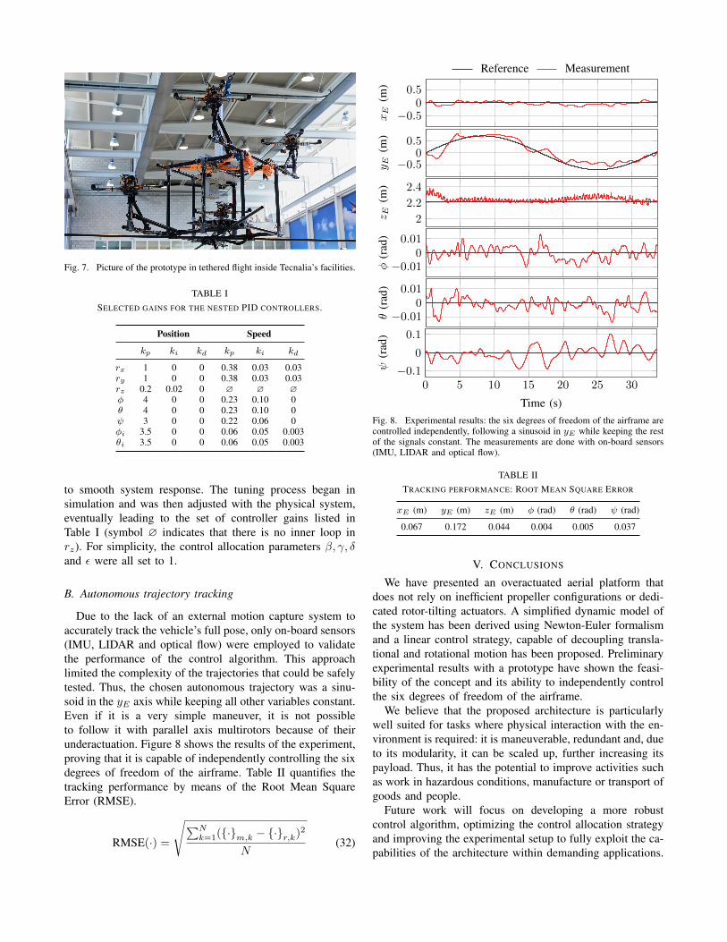
Fig. 7. Picture of the prototype in tethered flight inside Tecnalia’s facilities.
TABLE ISELECTED GAINS FOR THE NESTED PID CONTROLLERS.
Position Speed
kp ki kd kp ki kd
rx 1 0 0 0.38 0.03 0.03ry 1 0 0 0.38 0.03 0.03rz 0.2 0.02 0 ∅ ∅ ∅φ 4 0 0 0.23 0.10 0θ 4 0 0 0.23 0.10 0ψ 3 0 0 0.22 0.06 0φi 3.5 0 0 0.06 0.05 0.003θi 3.5 0 0 0.06 0.05 0.003
to smooth system response. The tuning process began insimulation and was then adjusted with the physical system,eventually leading to the set of controller gains listed inTable I (symbol ∅ indicates that there is no inner loop inrz). For simplicity, the control allocation parameters β, γ, δand ε were all set to 1.
B. Autonomous trajectory tracking
Due to the lack of an external motion capture system toaccurately track the vehicle’s full pose, only on-board sensors(IMU, LIDAR and optical flow) were employed to validatethe performance of the control algorithm. This approachlimited the complexity of the trajectories that could be safelytested. Thus, the chosen autonomous trajectory was a sinu-soid in the yE axis while keeping all other variables constant.Even if it is a very simple maneuver, it is not possibleto follow it with parallel axis multirotors because of theirunderactuation. Figure 8 shows the results of the experiment,proving that it is capable of independently controlling the sixdegrees of freedom of the airframe. Table II quantifies thetracking performance by means of the Root Mean SquareError (RMSE).
RMSE(·) =
√∑Nk=1({·}m,k − {·}r,k)2
N(32)
Reference Measurement
−0.50
0.5
xE
(m)
−0.50
0.5
y E(m
)
2
2.2
2.4
z E(m
)
−0.010
0.01
φ(r
ad
)
−0.010
0.01
θ(r
ad
)0 5 10 15 20 25 30
−0.1
0
0.1
Time (s)
ψ(r
ad
)
Fig. 8. Experimental results: the six degrees of freedom of the airframe arecontrolled independently, following a sinusoid in yE while keeping the restof the signals constant. The measurements are done with on-board sensors(IMU, LIDAR and optical flow).
TABLE IITRACKING PERFORMANCE: ROOT MEAN SQUARE ERROR
xE (m) yE (m) zE (m) φ (rad) θ (rad) ψ (rad)
0.067 0.172 0.044 0.004 0.005 0.037
V. CONCLUSIONS
We have presented an overactuated aerial platform thatdoes not rely on inefficient propeller configurations or dedi-cated rotor-tilting actuators. A simplified dynamic model ofthe system has been derived using Newton-Euler formalismand a linear control strategy, capable of decoupling transla-tional and rotational motion has been proposed. Preliminaryexperimental results with a prototype have shown the feasi-bility of the concept and its ability to independently controlthe six degrees of freedom of the airframe.
We believe that the proposed architecture is particularlywell suited for tasks where physical interaction with the en-vironment is required: it is maneuverable, redundant and, dueto its modularity, it can be scaled up, further increasing itspayload. Thus, it has the potential to improve activities suchas work in hazardous conditions, manufacture or transport ofgoods and people.
Future work will focus on developing a more robustcontrol algorithm, optimizing the control allocation strategyand improving the experimental setup to fully exploit the ca-pabilities of the architecture within demanding applications.

ACKNOWLEDGMENT
The authors would like to thank the following peoplefor their contributions and support (in alphabetic order):Leire Abad, Inigo Eguizabal, Jose Ramon Garcıa, EduardoGuzman, Mikel Lizeaga, Arkaitz Oyarzabal, Alexandre Paris,Andres Sierra, Tim Smithers and Haritz Vallejo.
REFERENCES
[1] H. Bonyan Khamseh, F. Janabi-Sharifi, and A. Abdessameud,“Aerial manipulation-a literature survey,” Robotics and AutonomousSystems, vol. 107, pp. 221–235, Sep 2018. [Online]. Available:https://doi.org/10.1016/j.robot.2018.06.012
[2] F. Ruggiero, V. Lippiello, and A. Ollero, “Aerial manipulation:A literature review,” IEEE Robotics and Automation Letters,vol. 3, no. 3, pp. 1957–1964, Jul 2018. [Online]. Available:http://doi.org/10.1109/LRA.2018.2808541
[3] A. Jimenez-Cano, J. Martin, G. Heredia, A. Ollero, and R. Cano,“Control of an aerial robot with multi-link arm for assemblytasks,” in 2013 IEEE International Conference on Robotics andAutomation. IEEE, 2013, pp. 4916–4921. [Online]. Available:http://doi.org/10.1109/icra.2013.6631279
[4] T. W. Danko and P. Y. Oh, “Design and control of a hyper-redundantmanipulator for mobile manipulating unmanned aerial vehicles,”Journal of Intelligent & Robotic Systems, vol. 73, no. 1-4, pp. 709–723,2014. [Online]. Available: https://doi.org/10.1007/s10846-013-9935-2
[5] T. W. Danko, K. P. Chaney, and P. Y. Oh, “A parallel manipulator formobile manipulating uavs,” in 2015 IEEE international conferenceon technologies for practical robot applications (TePRA). IEEE,2015, pp. 1–6. [Online]. Available: http://doi.org/10.1109/tepra.2015.7219682
[6] F. Ruggiero, M. A. Trujillo, R. Cano, H. Ascorbe, A. Viguria,C. Perez, V. Lippiello, A. Ollero, and B. Siciliano, “A multilayercontrol for multirotor uavs equipped with a servo robot arm,” in2015 IEEE international conference on robotics and automation(ICRA). IEEE, 2015, pp. 4014–4020. [Online]. Available: http://doi.org/10.1109/icra.2015.7139760
[7] A. Suarez, A. Jimenez-Cano, V. Vega, G. Heredia, A. Rodriguez-Castano, and A. Ollero, “Lightweight and human-size dual armaerial manipulator,” in 2017 International Conference on UnmannedAircraft Systems (ICUAS). IEEE, 2017, pp. 1778–1784. [Online].Available: http://doi.org/10.1109/icuas.2017.7991357
[8] B. Crowther, A. Lanzon, M. Maya-Gonzalez, and D. Langkamp,“Kinematic analysis and control design for a nonplanar multirotorvehicle,” Journal of Guidance, Control, and Dynamics, vol. 34, no. 4,pp. 1157–1171, 2011. [Online]. Available: http://doi.org/10.2514/1.51186
[9] G. Jiang and R. Voyles, “Hexrotor uav platform enabling dextrousinteraction with structures-flight test,” in 2013 IEEE internationalsymposium on safety, security, and rescue robotics (SSRR). IEEE,2013, pp. 1–6. [Online]. Available: http://doi.org/10.1109/ssrr.2013.6719377
[10] S. Rajappa, M. Ryll, H. H. Bulthoff, and A. Franchi, “Modeling,control and design optimization for a fully-actuated hexarotor aerialvehicle with tilted propellers,” in 2015 IEEE international conferenceon robotics and automation (ICRA). IEEE, 2015, pp. 4006–4013.[Online]. Available: http://doi.org/10.1109/icra.2015.7139759
[11] P. Roque and R. Ventura, “Space cobot: Modular design of anholonomic aerial robot for indoor microgravity environments,” in2016 IEEE/RSJ International Conference on Intelligent Robots andSystems (IROS). IEEE, 2016, pp. 4383–4390. [Online]. Available:http://doi.org/10.1109/iros.2016.7759645
[12] M. Ryll, G. Muscio, F. Pierri, E. Cataldi, G. Antonelli, F. Caccavale,and A. Franchi, “6d physical interaction with a fully actuatedaerial robot,” in 2017 IEEE International Conference on Roboticsand Automation (ICRA). IEEE, 2017, pp. 5190–5195. [Online].Available: http://doi.org/10.1109/icra.2017.7989608
[13] E. Kaufman, K. Caldwell, D. Lee, and T. Lee, “Design anddevelopment of a free-floating hexrotor uav for 6-dof maneuvers,” in2014 IEEE Aerospace Conference. IEEE, 2014, pp. 1–10. [Online].Available: http://doi.org/10.1109/aero.2014.6836427
[14] N. Staub, D. Bicego, Q. Sable, V. Arellano, S. Mishra, andA. Franchi, “Towards a flying assistant paradigm: The othex,” in2018 IEEE International Conference on Robotics and Automation(ICRA). IEEE, 2018, pp. 6997–7002. [Online]. Available: http://doi.org/10.1109/icra.2018.8460877
[15] H. Romero, S. Salazar, and R. Lozano, “Real-time stabilizationof an eight-rotor uav using optical flow,” IEEE Transactions onRobotics, vol. 25, no. 4, pp. 809–817, 2009. [Online]. Available:http://doi.org/10.1109/TRO.2009.2018972
[16] F. von Frankenberg and S. B. Nokleby, “Inclined landing testing ofan omni-directional unmanned aerial vehicle,” Transactions of theCanadian Society for Mechanical Engineering, vol. 42, no. 1, pp. 61–70, 2018. [Online]. Available: http://doi.org/10.1139/tcsme-2017-0008
[17] A. Nikou, G. C. Gavridis, and K. J. Kyriakopoulos, “Mechanicaldesign, modelling and control of a novel aerial manipulator,” in2015 IEEE International Conference on Robotics and Automation(ICRA). IEEE, 2015, pp. 4698–4703. [Online]. Available: http://doi.org/10.1109/icra.2015.7139851
[18] D. Brescianini and R. D’Andrea, “An omni-directional multirotorvehicle,” Mechatronics, vol. 55, pp. 76–93, 2018. [Online]. Available:http://doi.org/10.1016/j.mechatronics.2018.08.005
[19] S. Park, J. Lee, J. Ahn, M. Kim, J. Her, G.-H. Yang, and D. Lee,“Odar: Aerial manipulation platform enabling omnidirectionalwrench generation,” IEEE/ASME Transactions on mechatronics,vol. 23, no. 4, pp. 1907–1918, 2018. [Online]. Available: http://doi.org/10.1109/tmech.2018.2848255
[20] M. Tognon and A. Franchi, “Omnidirectional aerial vehicles withunidirectional thrusters: Theory, optimal design, and control,” IEEERobotics and Automation Letters, vol. 3, no. 3, pp. 2277–2282, 2018.
[21] D. Mellinger, M. Shomin, N. Michael, and V. Kumar, CooperativeGrasping and Transport Using Multiple Quadrotors, ser. SpringerTracts in Advanced Robotics. Springer Berlin Heidelberg, 2013,vol. 83, ch. chapter 39, pp. 545–558. [Online]. Available:http://doi.org/10.1007/978-3-642-32723-0 39
[22] Y. H. Tan, S. Lai, K. Wang, and B. M. Chen, “Cooperative control ofmultiple unmanned aerial systems for heavy duty carrying,” AnnualReviews in Control, vol. 46, pp. 44 – 57, 2018. [Online]. Available:http://doi.org/10.1016/j.arcontrol.2018.07.001
[23] C. Papachristos, K. Alexis, and A. Tzes, “Efficient force exertion foraerial robotic manipulation: Exploiting the thrust-vectoring authorityof a tri-tiltrotor uav,” in 2014 IEEE international conference onrobotics and automation (ICRA). IEEE, 2014, pp. 4500–4505.[Online]. Available: http://doi.org/10.1109/icra.2014.6907516
[24] Y. Long and D. J. Cappelleri, “Omnicopter: A novel overactuatedmicro aerial vehicle,” in Advances in Mechanisms, Robotics andDesign Education and Research. Springer, 2013, pp. 215–226.[Online]. Available: http://doi.org/10.1007/978-3-319-00398-6 16
[25] M. Ryll, D. Bicego, and A. Franchi, “Modeling and control offast-hex: A fully-actuated by synchronized-tilting hexarotor,” in2016 IEEE/RSJ International Conference on Intelligent Robots andSystems (IROS). IEEE, 2016, pp. 1689–1694. [Online]. Available:http://doi.org/10.1109/iros.2016.7759271
[26] M. Ryll, H. H. Bulthoff, and P. R. Giordano, “A noveloveractuated quadrotor unmanned aerial vehicle: Modeling, control,and experimental validation,” IEEE Transactions on Control SystemsTechnology, vol. 23, no. 2, pp. 540–556, 2015. [Online]. Available:http://doi.org/10.1109/tcst.2014.2330999
[27] A. Oosedo, S. Abiko, S. Narasaki, A. Kuno, A. Konno, andM. Uchiyama, “Flight control systems of a quad tilt rotor unmannedaerial vehicle for a large attitude change,” in 2015 IEEE InternationalConference on Robotics and Automation (ICRA). IEEE, 2015,pp. 2326–2331. [Online]. Available: http://doi.org/10.1109/icra.2015.7139508
[28] M. Kamel, S. Verling, O. Elkhatib, C. Sprecher, P. Wulkop, Z. Taylor,R. Siegwart, and I. Gilitschenski, “The voliro omniorientationalhexacopter: An agile and maneuverable tiltable-rotor aerial vehicle,”IEEE Robotics & Automation Magazine, vol. 25, no. 4, pp. 34–44, Dec2018. [Online]. Available: http://doi.org/10.1109/mra.2018.2866758
[29] P. Segui-Gasco, Y. Al-Rihani, H.-S. Shin, and A. Savvaris, “A novelactuation concept for a multi rotor uav,” Journal of Intelligent &Robotic Systems, vol. 74, no. 1-2, pp. 173–191, 2014. [Online].Available: https://doi.org/10.1007/s10846-013-9987-3
[30] M. Odelga, P. Stegagno, and H. H. Bulthoff, “A fully actuatedquadrotor uav with a propeller tilting mechanism: Modeling andcontrol,” in 2016 IEEE international conference on advanced

intelligent mechatronics (AIM). IEEE, 2016, pp. 306–311. [Online].Available: http://doi.org/10.1109/aim.2016.7576784
[31] M. Nigro, F. Pierri, and F. Caccavale, “Preliminary design,modeling and control of a fully actuated quadrotor uav,” in2019 International Conference on Unmanned Aircraft Systems(ICUAS). IEEE, 2019, pp. 1108–1116. [Online]. Available: http://doi.org/10.1109/icuas.2019.8798092
[32] N. Michael, J. Fink, and V. Kumar, “Cooperative manipulationand transportation with aerial robots,” Autonomous Robots, vol. 30,no. 1, pp. 73–86, 2011. [Online]. Available: http://doi.org/10.1007/s10514-010-9205-0
[33] R. Ritz, M. W. Muller, M. Hehn, and R. D’Andrea, “Cooperativequadrocopter ball throwing and catching,” in 2012 IEEE/RSJInternational Conference on Intelligent Robots and Systems. IEEE,2012, pp. 4972–4978. [Online]. Available: http://doi.org/10.1109/iros.2012.6385963
[34] K. Sreenath and V. Kumar, “Dynamics, control and planning forcooperative manipulation of payloads suspended by cables frommultiple quadrotor robots,” Proceedings of the Robotics: Science andSystems Conference (RSS), vol. 1, no. r2, p. r3, 2013. [Online].Available: http://doi.org/10.15607/rss.2013.ix.011
[35] M. Manubens Ferriol, D. Devaurs, L. Ros Giralt, and J. Cortes,“Motion planning for 6d manipulation with aerial towed-cablesystems,” in Proceedings of the Robotics: Science and SystemsConference (RSS), 2013. [Online]. Available: http://doi.org/10.15607/rss.2013.ix.028
[36] M. Gassner, T. Cieslewski, and D. Scaramuzza, “Dynamiccollaboration without communication: Vision-based cable-suspendedload transport with two quadrotors,” in 2017 IEEE InternationalConference on Robotics and Automation (ICRA). IEEE, 2017,pp. 5196–5202. [Online]. Available: http://doi.org/10.1109/icra.2017.7989609
[37] T. Lee, K. Sreenath, and V. Kumar, “Geometric control of cooperatingmultiple quadrotor uavs with a suspended payload,” in 52nd IEEEConference on Decision and Control, Dec 2013, pp. 5510–5515.[Online]. Available: http://doi.org/10.1109/cdc.2013.6760757
[38] D. Six, S. Briot, A. Chriette, and P. Martinet, “The kinematics,dynamics and control of a flying parallel robot with three quadrotors,”IEEE Robotics and Automation Letters, vol. 3, no. 1, pp. 559–566, Jan2018. [Online]. Available: http://doi.org/10.1109/lra.2017.2774920
[39] H.-N. Nguyen, S. Park, J. Park, and D. Lee, “A novel robotic platformfor aerial manipulation using quadrotors as rotating thrust generators,”IEEE Transactions on Robotics, vol. 34, no. 2, pp. 353–369, Apr2018. [Online]. Available: http://doi.org/10.1109/tro.2018.2791604
[40] A. Tagliabue, M. Kamel, R. Siegwart, and J. Nieto, “Robustcollaborative object transportation using multiple mavs,” TheInternational Journal of Robotics Research, vol. 38, no. 9, pp.1020–1044, Aug 2019. [Online]. Available: http://doi.org/10.1177/0278364919854131
[41] S. Bouabdallah, “Design and control of quadrotors with applicationto autonomous flying,” Ph.D. dissertation, Ecole PolytechniqueFederale de Lausanne (EPFL), Lausanne, 2007. [Online]. Available:http://doi.org/10.5075/epfl-thesis-3727
[42] B. Etkin and L. D. Reid, Dynamics of flight. Wiley New York, 1959,vol. 2.
[43] L. Meier, D. Honegger, and M. Pollefeys, “Px4: A node-basedmultithreaded open source robotics framework for deeply embeddedplatforms,” in 2015 IEEE International Conference on Robotics andAutomation (ICRA), May 2015, pp. 6235–6240. [Online]. Available:http://doi.org/10.1109/icra.2015.7140074
[44] D. Honegger, L. Meier, P. Tanskanen, and M. Pollefeys, “An opensource and open hardware embedded metric optical flow cmos camerafor indoor and outdoor applications,” in 2013 IEEE InternationalConference on Robotics and Automation (ICRA), May 2013, pp. 1736–1741. [Online]. Available: http://doi.org/10.1109/icra.2013.6630805