I .~I GEOLOŠKI ZAVOD SLOVENIJE ~.Dimičeva ulica … · Gen-Energija,d.o.o. Consortium partners:...
62
GEOLOŠKI ZAVOD SLOVENIJE ulica 14,1001 Ljubljana GeolS Geotechnical, Geological, and Seismological (GG&S) Evaluations for the New Nuclear Power Plant at the Krško Site (NPP Krško II) Paleoseismological trenches on the libna Hill Revision 1 UUBUANA, April 2011
Transcript of I .~I GEOLOŠKI ZAVOD SLOVENIJE ~.Dimičeva ulica … · Gen-Energija,d.o.o. Consortium partners:...

I.~I GEOLOŠKI ZAVOD SLOVENIJE~. Dimičeva ulica 14,1001 Ljubljana
GeolS
Geotechnical, Geological, and Seismological (GG&S) Evaluations for
the New Nuclear Power Plant at the Krško Site (NPP Krško II)
Paleoseismological trenches on the libna Hill
Revision 1
UUBUANA, April 2011

Project :
Phase:
Contraet :
Investor:
Geotec hnkal, Geo logical, a nd Setsmolog tca l (GG&S) Evalua uons tor the New Nuclea r Powe r Pla nt a t the Krško Site INPP Kr~ ko It)
Geotechnical, Geological, and Seismological (GG&S)Evaluations for the New Nuclear Power Plant at the
Krško Site (NPP Krško II)
IS!, Addendum 1
Consortium agreement 1130-167/07, Addendum 1
Gen-Energija, d.o.o.
Consortium partners :
Responsible for Consortiumleader BRGM. Project leader:
Responsible fo r task leaderGeoZS. Director:
Report/task
Responsible:
Reviewer:
Approbation :
Arch . No. GeoZS:
Place and date:
GeoZS
BRGM
IRSN
BRGM, GeoZS, IRSN, ZAG
Behrooz Bazargan Sabet
Marko Komac
Miloš Bavec
Monique Terrier
Stephane Baize
J-II-30d/ b6b-4/ 3-d
Ljubljana, April zo". 2012
Paleoseismological surv ey on Ule Libna Hill 1

(,potechfllc al, Geologrcal, and Seurnolcg. ca t (GG& SI I valu auo ns IOf the New Nuctear Powe r Plan t al th e Kri ko 51te (NPP Krško II I
Baize Stephane IRSN
Bavec Miloš GeoZS
Jomard Herve IRSN
Contributors : Milan ič Blaž GeoZS
Mišič M iha GeoZS
Poljak Marijan GeoZS
Rižnar Igor Consultant
Skaberne Dragomir GeoZS
KEY WORDS : NPP Krško II. paleoseismology. trench. Libna fault. Libna Hill
Paleoseism ological survey on the Libna Hill 2

Geo technkal, Geotog tcal. and Seumologtcal (GG&S) Evaluatlonl for the New Nuclear Power Piani at the Kriko SIle (NPP Krlko II)
Lis t of Contents
1 SUMMARY 5
2 INTRODUCTION 6
3 TRENCHES ON LIBNA 8
3.1 TRENCH 1 , 11
3.2 TRENCH 2 12
3.2 .1 Generaloverview of findings in trench 2 12
3.2.2 Detailed description and sedimentological interpretation of sedimentary units 16
3.2.3 Age dating of sediments 29
3.2.4 Deformation pattern in Trench 2 and tectonic interpretation 34
3.2.5 Evaluation of displacement along the Libna fault from findings in and near trench 2.38
3.3 TRENCH 3 , 40
3.3.1 Generaloverview of findings in trench 3 40
3.3.2 Description and interpretation of main sedimentary units 42
3.3.3 Structural observations 48
3.4 Analysis of granulometric, mineralogical and chemical composition of sediments in
Trenches 2 and 3 49
3.4.1 Overview of laboratory results and the statistical (cluster) analysis 49
3.4.2 Conclusions from analyz ing the mineralogical, granulometric and geochemical
composition of sediments 53
4 POTENTlAL IMPLlCATIONS OF NEW FINDINGS FOR SEISMIC HAZARDAND CAPABLE FAULT
ISSUES 55
4.1 LIBNA FAULTAS A CAPABLE FAULT 55
4.2 LIBNA FAULTAS A SECONDARY STRUCTURE, ACTIVATED BYA NEARBY SEISMIC SOURCE? 56
4.3 LIBNA FAULTAS A SOURCE IN SEISMIC MOTION CALCULATION? 56
4.4 ADDRESSING THE AMBIGUITIES 57
5 CONCLUSIONS 58
6 REFERENCES , 59
Paleoseismo logica l sur vey on the Libna Hill 3

Geotechmcal, Geolo gical. and SeI!.mologicaI IGG&SI Evaluat ions for the New Nudear Power Plant at the Krško Sit e (NPP Krško II)
List of Appe ndi ces
Appendix 1 External expert report Daniela Pantosti
Appendix 2 Archeology report S. Porenta & M. Novšak; Arhej d.o .o.
Appendix 3 Archeology supplement report T. Verbič & S. Porenta; Arhej d.o.o.
Appendix 4 Displacement modeling Branko Mušič; Gearh d.o.o.
Appendix 5Mineralogy, Geochemisty in
D. Skaberne & M. Mišič, GeolSGranulometry data
Appendix 6 14C dating report R.E. Hatfield & D. Hood; Beta Analytic
Appendix 7 Luminescence dat ing report F. Preusser; Stockholm University
Appendix 8 Comments on ESR dating resultsP. Voinchet; Museurn national d'Histoire
naturelIe, Paris
Paleoseismological survey on the Libn a Hill 4

Geotechncal. Geolo gical. and Seismclogfcal (GG&Sj Evaluanons for the New Nuclear Pow er Plant at th e Krško Site INPP Krško II)
1 SUMMARY
Three paleoseismological trenches were excavated within the zone of the Libna fault in fali 2010. Thezone of Libna fault was interpreted to be between 150 and 200 m wide.
Selection of the sites on the Libna Hill was made upon significant geophysical campaign and a seriesof test pits.
Two of the three trenches were logged and interpreted in detail. One trench (trench #1) collapsedduring the excavation. After the collapse the geometry of the other two trench walls was changed bybuilding horizontal steps into the walls to avoid collapsing.
Trench #2 showed the most significant results, while trench #3 provided certain important additionalinformation. Bulk of most important information is therefore summarized in the chapter"Dejormation pattern in Trench 2 and tectonic interpretation"
General stratigraphy of the trenched area is (from oldest to youngest): Badenian (Lithotamnian)limestone, " residual day" on the Badenian limestone, Plioquaternary gravel and sand, Plioquaternarysilt, colluvium (at places) and modern soil.
ln trench #2 it is interpreted that a dextral stri ke slip fault with certain vertical component is present.The general strike of the fault is NW-SE and the dip of striae indicates that the slip varies from O· to30· SE.
ln trench #2, two main fault zones are observed along with an anastomosing system ofaccompanying fractures that cover the whole logged length of the trench (app. 26 m) and mostprobably extends also outside the trench toward ENE.
The Plioquaternary series is displaced in trench #2 and the displacement is significant.
Continuation of deformation upward into younger sediments in t rench #2 (dated by archeologicalfindings) is less obvious and several interpretations are presented in the report. In trench #3 thedeformation does not propagate into the Plioquaternary succession but stops underneath.
The evaluation of displacement was only possible by combining results of additional geophysicalsurvey (GPR and ERT) and observations in trench, and this was only possible along one of the twofault zones in trench #2. This displacement is evaluated to several meters (less than 10 ml. Fulldisplacement along the Libna fault is larger and distributed among other fault planes.
According to the current tectonic model , the potential displacement is not distributed evenly alongthe whole length of the Libna fault . It is concentrated mostly to differential folding along the Libnaantidine and most deformation should be taken up the re (on the Libna ant idine) .
ESR and OSL dates were obtained for the terrestrial Plioquaternary series during the course of th isproject that are surprisingly low (210.000 to 130.000 B.P.) for Globoko format ion compared to theestimate of 1 - 2 million years before this project. At this stage, we cannot apply these age dates intothe regional geological model (also outs ide Krško basin) so we decided to wait with furtherapplication until they are praven by independent analyses.
Paleose ismological survey on the Libna Hill 5

Geot echn cal. Geological, and Sefsmo logtcal (GG&S) Evaluaucns for the New Nuclear Power Plant at the Kr1ko Site (NPP Krika II)
2 INTRODUCTION
Through Phase I of the project Geotechnical, Geological, and Seismological (GG&S) Evaluations forthe New Nuclear Power Plant at the Krško Site (NPP Krško II), a series of evidences was obtainedindicating that the Libna fault, a NW-SE trending strike-slip fault near the proposed sites for the NPPmay be a capable fault (Fig. 1). The surveying described in this report followed a series of focusedpaleoseismological actions taken between 2008 and 2010 (described in the Phase 1 Geology report;Bavec, ed., 2010). The paleoseismological survey on the Libna hill is a contractual task controlled bythe Addendum 1 to the main contact between GEN energija d.o.o. and the Consortium (BRGM,GeoZS, IRSN, ZAG).
Fig . 1 . Loco ti on oj tr enches on the Libno /fill w i th respect to the Libno f oult (t wo lin es indico te the
opp roxim o ted widt h of th e f ou lt zo ne) and the tw o proposed si tes. The tren ch a t Sta r i Grad (repor ted
in 20(8) i~ 0 150 sho w n.
ln 2008, the first paleoseismological trench was excavated in the Sava alluvial plain across thewestern boundary of the geophysical anomaly band that is interpreted to be the Libna fault imprint.This trench crossed a segment of NW-SE strike-slip fault cutting the Pontian silts, but the expressionof the fault in recent deposits was questionable. In deta il, it has only been possible to observe anambiguous step in the interface between Pontian silts and Holocene Sava alluvium, at the location ofthe fault zone in Pontian units. A set of linear "negative" imprints with individuallengths of 10-15 cmwere also observed along this step, and it was suggested that these could have been generated bypebbles scratching the slickenside during a faulting event. A possibility of faulting activity duringrecent time has then been pointed out. However, no recent deformation was univocally interpretedand no deformation was observed propagating within the fluvial sediments (only 400 years oldthere). Because of this ambiguity of interpretation, together with the very young age of the upperfluvial sediments, it was then decided to perform additional investigations where the fault wassuspected to cut older sediments in the Libna Hill.
Revision 1 of the report as presented here is taking into account 1) findings of the revision providedby GEN Energija (Technical report Designation TP-012, Revision 1 Comments on GG&S
Paleoseismological survey on the Libna Hill 6

Geot ec hnk al, Geolog jcal, and Seu mologtcal (GG& S) Eveluauons for the New Nuclea r Powe r Pia ni al the Krško Site (NPP Krško II)
"Paleoseismologi cal trenches on the Libna Hill " Report), dated 19.12.2011,2) independent review ofPaul C. Rizzo Associates (Final Report; Independent technical review of the paleoseismolog icaltrenches on the Libna hill report), dated January si" 2012 and 3) f ind ings of t he review meeting inOrleans, F. on December 13-14th , 2011 as documented in Minutes of meet ing: Status and proposedactivities on Libna geological feature.
Paleoseismological survey on the Lib na Hill 7

Geotec hnk al. Geologtcal. and Seu mological (GG& S) Evaluatio ns for the New Nudear Power Plant at the Krško Sile (NPP Krško II)
3 TRENCHES ON LIBNA
Technical information and the team
Afte r significant geophysical campaigns on the Libna hill and logging of several test pits, three trenchsites were finally selected (Fig. 2): two trenches were excavated on the western edge of the Libnafault zone (trenches #1 and #2) where the geophysical signal of deformation was shown as mostprominent, and one inside the Libna fault zone (trench #3). Trench #1 was dug first, butunfortunately collapsed a few hours after because of slope instability angle and poor soil conditions .To enable further work and primarily for safety reasons, the geometry of other two trenches wasadopted by int roducing a step in their vertical walls . Trench #3 was then successfully excavated in theBadenian limestone and its residual clay, with two non-deformed superficial layers of colluvium andPlioquaternary silt with pebbles, overlying it. Tectonic deformation observed in trench 3 was minorcompared to the trench #2.
Fig. 2. LocotlolJ oj trenciics on the Libno hill wi th t espect to opproximoted ouiei boundories oj thewides t , ib no [o ul! ro ne .
Trench #2 gave t he most signif icant results with respect to the initial objective, which was primarilyto validate or not the post-Plioquaternary activ ity of the Libna fault. Post-Plioquaternary activity ofthe Libna fault was proven.
Paleoseismologica l sur vey on the Libna Hill 8

Geot echnk al, Geolo gjcal, and Seismological (GG&S) Evaluanons for the New Nuctea r Power Plant at t he Kri ko Site (NPP Krško II)
Corner coordinates Orientation ElevationLenght (m) (azimuth°) Depth (m) [Iowest-
1 2 3 4 highest (m))
15°31'01.62" 15°31'01.68" 15°30'59.84" 15°30'59.90Trench 1 13+37' 60 3,5 - 4,0 278 284
45°57'05 .93" 45°57'05.88" 45°57'04 .89" 45°57'04.84"
15°30'57.37" 15°30' 57.46" 15°30'55.11" 15°30' 55.12"Trench 2 37,3 65 76 85 1,6 - 4,0 309 315
45°57'08.93" 45°57'0 8.80" 45°57' 08.46" 45°57'08.33"
15°31'04.18" 15°31'04.28" 15°31'03.22" 15°31'03.25"Trench 3 24 56 1,6 - 3,8 289 294
45°57' 07 .05" 45°57' 06.94" 45°57'06.61 " 45°57' 00.04"
, excaval ed befor e collapse+planned
Table 1. Technical deta ils of th e trenches
Trenches were logged and interpreted by GeoZS (Dragomir Skaberne, Igor Rižnar, Blaž Milanič, MilošBavec) and IRSN (Stephane Baize, Herve Jomard) and with assistance of students of geology at theUniversity of Ljubljana (Klemen Černič, Rok Brajkovič, Dejan Emeršič, Domen Bajec, Anže Merkelj) .Responsible for this task is M. Bavec, GeoZS who also edited the report . The report is written by thewhole professional part of the team .
Excavation started on zs" Sept . 2010 with trench #1, which collapsed the same day. Excavation fortrench 3 was done on 7th and s" Oct; gridding, logging and sampling lasted unt il 14th Oct, .2010.Trench2 was excavated between n " and ia" of Oct. 2010. Gridding, logging and sampling was donebetwee n iz" and 22nd Oct. 2010. The first findings have shown potential high importance of resultsthus Daniela Pantosti (INGV Rome) was invited in the power of invited External Expert. Shejoined theteam for the last two days in field and has reported her conclusions based on her field observations(Appendix 1). After initial interpretations were made, the team revisited the site for additionallogging and sampl ing on 24th and zs" Nov. 2010.
Exact position of tren ches is presented in Table 1 and in Fig. 3.
Paleoseismological survey on the Libn a Hill 9

Geot echnical, Geolo gical, and Selsrnclo glcal (GG&SI Evaluat ions for the New Nuclear Power Plant al the Krik a Sile IN PP Kd ko II)
Fig . 3. Exa ct loco t io n of trell !Jf S 0 11 ti le Libno !J ill und qeoni etric det oils.
During the course of excavation of the trench #2, archeological remains were discovered . The
National Agency for Cultural Heritage (Zavod za varovanje kulturne dediščineSlovenije) was informedand protective archeological excavations were ordered. Archeological excavations were conducted
by Arhej d.o.o and were lead by Matjaž Novšak and Andrej Porenta. The same company wasconsulted also regarding the finding of the silex artefact in the trench and regarding the archeological
interpretation of the interface between the "cultural" and "geologic" layers . Archeological report isappended (Appendices 2 and 3).
Additional geophysical survey was ordered after first observations were gathered, to help evaluatingdisplacement along the fault. It was conducted by Gearh d.o.o. and lead by Branko Mušič (Appendix4).
This report presents the joined interpretation of the working group.
At the end of this report (section 5) the Consortium proposes further actions for c1arification ofactivity and geometry of the Libna fault.
Paleoseism ological survey on the Libna Hill 10

Gectechmcal, Geological, and Seumc loglcet (GG&S) Evaluat tcns for the New Nuclear Power Piani at the Kriko SIle INPP kriko Il)
3.1 TRENCH 1
Trench 1 was planned to be excavated along the trace of the most prominent geophysicaly observeddeformation (as well as trench 2) across a relatively steep slope. Unfortunately, by excavation theslope instability was initiated and the trench collapsed and was not logged (Fig. 4)
Fig. 4. tni ti ot i on oj excovo tio n in tre ncb #1 (lejt) and th e co llapse oj the wa ll that sto pped the works
(r igh t). Not e the contact of PI,Q sed irnen ts w i t l : Bod enian timestone on the ri ght oia ure
Paleose ismol ogical survey on the Libna Hill 11

Geotechntcel, Geolog. cal. and Sersmclogrcal (GG&5) Ivaluations for the New Nuclear Power Plant at the Krško Site (NPP Kri ko II)
3.2 TRENCH 2
3.2.1 Generaloverview of findings in trench 2
Trench 2 can be described as the juxtaposition of 3 blocks separated by 2 main fault zones (Fig. 4). Inthe western side of the Trench, the fault zone 1 (FZ1) separates the Badenian limestone and its"residual clay" from the major mass of brown Plioquaternary silts (Fig. 5; Fig. 6) laying above thePlioquaternary (PI,Q) gravel and sand. To the east, the brown silts are in tectonic contact with thegravel and sand (fault zone 2, FZ2). The section is topped by a modern soH layer (including thearcheologicallayer) which seems undeformed by the post-Plioquaternary faults .
FigA . t rencb 2 dur ing cleaning and ex tro cuon oj m eteot ic wa ter . Fault zones Fll and Fl 2 are
m or ked.
One can observe a large amount of deformation features in the trench walls and floors, withfractures, fissures (filled with silt) and faults with apparent displacements. Vertical and horizontalsections present in the fault zone 1 (FZ1) area show that deformation is distributed along manyfractures that juxtapose many blocks of silts, c1ays and PIQ gravels. This great number of tectoniclenses suggests that the cumulative displacement is substantial (more than just a few meters) . Thesecond fault zone separates the silts, from the weathered gravel and sand, and coincides with thethickening of the modern soil, and the location of an iren-age house discovered during the trenchanalysis. Faults and fractures are generally subvertical, or steeply dipping to the ENE. Together withthe main faults, the secondary network of fractures forms an anastomosing system. In addition, thestratigraphic conditions in the trench do not allow direct estimation of the offset along the faults (FZ1and FZ2) . Namely, the base of the (PI,Q) silt in the structural block between the fault zones (FZ1 andFZ2) is not known and the silt there is much thicker than in the easternmost block, where the base of
PaleoseismologicaJ survey on the Libna Hill 12

Geo techn cal, Geological, and Setsrnologica l (GG&S)Evaluation! for the New NucJear Power Plantal the Krško Site INPP Krško JI}
the silt is observed. All these observations, together with the finding of a gently dipping striation onthe fault planes indicate that deformation is associated with dextral strike-slip movements (with anon-negligible vertical component) along the general strike of the Libna fault (NW - SE).
A general observation is that faults and fractures cross all the series (Limestone, PIQgravels and silts)up to the soil interface which seems to be undeformed.
Fig. 5 : The two f au Jt zones expos ed in the Trench 112; [ioc tures ond f oult p lones are underlined by red
[Iogs . To the lej t, Fll bet» een the limestone with tile "residuai lov" (l ight) an d th e bro wn sitts (left)
is mode of vor io us lenses (th e m ost prominent is the red on e, at th e bo ttom oj the ttench, which
involves the pebb les oj the Plio quate rna ry gra vel and sond). To the ri ght, FZ2 between Plioq ua ternary
gravel and sond (lejt) ond bro wn s/li s (r ight) is 0 150 mode oj var iou s st ronds with lorge vor io ti on in
suike.
It is important to underiine that the most significant fault plane within FZ2 ends beneath the Iren-agesoil with soil infiltrations downward into the fault gouge. The infiltration can be interpreted as aninfill of an open crack, which could have been formed during adeformation event. In strike-slip"environment", the identification of deformation events (like earthquakes) is not an easy task.Classical criteria such as "fracture upward terminations" beneath success ive laminations,"unconformities" or even "colluvial wedges" (see Mac (alpini 2009 for a synthesis) were notobserved here. Some authors (e.g. Lienkaemper and Williams, 2007) also define fissure fills asfeatures unique to coseismic displacements. However, if the observed infiltration features wereindeed opening of fault plane and fissures with soil infiltration (V-shaped cracks) it would suggestthat coseismic deformation could have occurred on these faults during or just after the soil
Paleoseismological survey on the Libna Hill 13

Geo techmcal. Gl'ological, and Sebmologrcal (GG&SI Evakratro r u to r t he New Nuclear Powe r Piani at t he Kri ko Sile (NPP K r ~k o III
formation . The presence of such open cracks near the soil base, not erased by the pre-archeologicalerosion period (ie. during glacial period) would also indicate that the observed deformations arequite young (post glacial period) . At least two "non-seismic" interpretations of V-shaped cracksgenesis are also possible of which the following cannot be rejected by our findings: 1) opening ofcracks due to mass movement (the modern surface is inclined at about 10°) and 2) desiccation . Aplausible interpretation of soil infiltration is also infiltration of fault gouge by bioturbat ion for whichno open cracks are needed or simply alterat ion of fault gauge by water inf ilt rat ion. For discussion onthese interpretations see section 3.2.4. of th is report .
Our primary position based on the data presented in this report is that the significant deformationends in the stratigraphic unit called here the Plioquaternary silt and that the deformation does notpropagate into historic layers above. The age of the last deformation is thus controlled by the age ofthe PIOsilt (younger than PIOsilt and older than the Hallstatt culture). A further alternative, which isnot definitely demonstrated, favors a tectonic (also coseismic) interpretation of the modern soilinfiltration into the fault gouges, which dates the latest deformation to Holocene. This interpretationis presented by the consulted external expert Daniela Pantosti (Appendix 1).
Another impacting difference in potential interpretation is related to the genesis of the whole (or apart of the) silt unit (called here the Plioquaternary silt) as colluvial and to the position of the silexartefact within this siIt. According to interpretation of D. Pantosti (Annex 1), the silt mav be colluvialthus the silex artefact (200.000 to 2.500 Be) mav have been deposited within the colluvium(synchronous with deposition) and thus predates the deformation along the fault . This interpretationis not well demonstrated as to begin with, the silt is definitely of fluvial origin (except possibly theupper 10-20 cm). There are other possible interpretations of the artifact position sueh as infiltrationinto a crack that has not been opened coseismically, or the one suggested by the archeologicalexpert that the artefact could have been pushed downward into the silt by bioturbation (seeAppendix 2) or by other means (for discussion on artifact position see section 3.2.4).
Paleoseismological survey on the Libna Hill 14

Geotc chmcal. Geolo g-cal, an d Seisrnc togtcal (GG&S) Evaluallons for the New Nuc~ar Pow er Pbnt at the Krno SitE' (NP P Krško II)
Archeoloqical houseOSL F: 1)4 1 11 Il.OSLO 10101U1l.l
A WSW
Q·E
• c·o
C 1. · • .,h
.~ F'l:- _
tOS l. F . ,O!l.O ... 0 ....
Fault zone 1
Bnck fragment
00,5 1 2 3 4 m! I I I I
Sati
SIli
Fault zone 2
sanos
gravels_ reSldual 'd ay'
lithotamnlanlImestone
.. arcneotoqrcal toot
bod. fragments
oxydrsed pebblesand Fe-Mn con crenons
samples
mtractasts•faun plane
_ brecc,a
•• OSL and C 14 date.
......
ground surtace--- Interface solVPho-Q uaternary
dltfuse So
mass-v e SOSO
-- hydromorphrc mottling
-- T,ench Slep
H
G
FENE
possib ie faullsecondary faut!or fraeture
-- mainfaull- - taul1wrth apparen t
ma/or offset
STEP MOSAIC
so-- lauIIA & flKIul
.•
Irorth
. ~7~8~9,30
FLOOR MOSAIC
Fig, 6 The log of Trench
Paleoseismological survey on the Libna Hill 15

Geo techmc al, Geolo g.cal.• md Sersmolog tca l (GG&SI Evalua tron s fO I the New Nuclear Power Plant al th e K r~ko Site INPP Kd ko II)
The absolute age dates for the PIQ series (the Globoko aloformation) were obtained after severalpast attempts for the first time within this project (and for the first time in the region) and areunexpected. ESR (from the Globoko locality but for the same geologic aloformation) and OSL dates
(from the trench) coincide relatively well and estimate the age at around 210.000 and 130.000 yearsBP respectively . A leap from previous age est imates (ranging from 0.3 to 5 million years; e.g. Swan etal., 2004) and by most authors to between 1 and 2 million; e.g. Šikic et al., 1979; Verbič, 2004) is
enormous and we cannot fit these new age estimates into the regional geological interpretations. Forthat, we are using the new age dates more as one of options and not as solid facto The age - datingresults are discussed in section 3.2.3 of this report.
The displacement along the fault was evaluated solely by amodel, based on bedding plane
orientation in trench and on the geophysical evaluation of continuation of the Iithological unitsoutside the trench. The piercing points for such an evaluation were not found within the trench at
both sides of the fault, and further excavation was not possible due to archeological protection of thearea. Cumulative displacement along one of the two fault zones (the one with enough "geophysical
contrast": FZ 2; maybe the one with less displacement accumulated) is estimated at the order ofmagnitude of several meters (less than 10 ml.
The SW wall of the trench 2 was logged in deta il, while opposite wall was used for gathering
additional information. The floor and the "step" (created to enable stability of wall) of the trench
were also logged (Fig. 6).
3.2.2 Detailed description and sedimentological interpretation of sedimentary units
Three main sedimentary sequences are outlined in trench2. The oldest and lowermost sequenceconsists of the Badenian limestone ove ria in by the "residual day". The middle and most prominent
sequence consist of gravel, sand and silt of the Plioquaternary age. The most recent sequence is a soilof the Holocene age. Badenian limestone, overIain by the "residual day" is in the fault contact withthe Plioquaternary silt but the Holocene soil forms a cap covering the "residual day" andPlioquaternary gravel, sand and silt.
3.2.2.1 The Lithotamnian limestone - Badenian
Lithotamnian limestone of the Badenian age crops out at the WSW side of the trench 2 against FZ1and continues to the west in the Libna hill. It is the oldest formation observed in the trenches. In the
trench 2, it was exposed in the thickness of up to 2.5 m. This homogenous limestone is in tectoniccontact with the brown silt of the Plioquaternary age at the 5.6 to 6.0 m (FZ1). It appears affected byshearing and it is intensely weathered and covered by a thick sedimentary cover of red silty day(referred to as the "residual day") in the western most part of the trench. The latter is eroded at theWSW side of the trench (outside the logged section), and the limestone is covered there only by
modern soil (Fig. 7;).
Paleoseismologtcal survey on the Libna Hill 16

e eo tec bnc af. Geological, and Selsmologi caI IGG&S) Evalua uon s for the New Nudear Power Plant at tM Kri ka Site (NPP Krike II)
Fig 7 Badenittn iimes ton I!> (Over Jby th e • i esiduot etov" , wil i/ a l l ik W5 W t ip (tr en cl. bac k, be ilInd
ti le ma n] of the trendi i t is covered cm /v IJy (1 r cen t soil.
Macroscopically, the limestone is described as white Lithotamnian bindstone and calcarenite withfragments of bivalves, bryozoans and foraminifers encrusted by red algae (Lithotamnian) that mayform rhodolites. The limestone is also intensively karstified forming very uneven corroded surfacewith deep indentations also filled by the "residual day" (Fig. 8).
Fig . 8 . 7he Litho tha m nia n limeston e is m ass/ve, jracture d, weo thered and int ensivelv korstijieo. The
co n tact w it h tt ie rresiduo ! cloy" is vet y uneven and cor roded . There are isotatetl corrodeti !ragment s
oj timesu»: in the ' resuiuo! clov" the 5W wall oj I h u ench, bet w een o p. 1-8 n i.
3.2.2.2 The "residual day"
The massive silty day referred here to as "residual day" is Iying above the karstified surface of theLithotamnian limestone and is overIain by soil (Fig. 8). It is up to 1 m thic k and is eroded in the WSWend of the trench (Fig. 7). The color of the " residual day" is light brown to brown (5YR4-5/6) . It
Paleoseismological survey on the Libna Hill 17

Geotechmcal, Geolo g.cal. and Setsrnolcgtcal (GG&S) Evaluanons for the New Nuc lear Power Plani at th e Kri ko Site (NPP I(rl ko Il)
consists on average 81 % silt, 18 % clay and 1 % sand grain size fraction (Appendix 5). According tothese data the clay should in fact be named silt but is kept here with quotation marks for easier
divis ion with other Iithologic units in the trench. Its mineralogical composition is: quartz 10 %,plagioclase 2 %, muscovite/illite 55 %, chlorite 28 % and goethite 6 % (Appendix 5). Muscovite is
weathered to less well crystallized illite.
Sedimentological interpretation: The " residual clav" is interpreted as paleosoil - chromic (brown)cambisol developed on the Lithotamnian limestone during its exposure and before deposition of thePlioquaternary sediments. The presence of allochtonous, most probably aeolian maternal, as known
in many soils of "terra rosa" in the Mediterranean region is described in section 3.4.1.
3.2.2.3 The gravel and sand o/the Globoko Formation - Plioquaternary
Gravels with lenses of sand occupy most of the trench 2 between 18 and 31 m. The gravels areoveriain by brown silt. At 18 rn, the gravels are in a tectonic contact with the brown silt (Fig. 6).
Gravely and sandy Iithofacies are forming about 3.7 m thick sequence in which five sedimentary unitswere ident if ied (Fig. 9).
lig . :J l iJe su cccssion of UII'/S 7, .J, 3 a nd 4. II !r OCIIJII' JI/led LJ y s/lt l il tne uppc : iioh ! siao l he _~ VV w el l
of tl i(' tre ncli, U /(l I lI i '-! 2;; /I ! .
The colors of these gravely lithofacies are mostly pale to moderate yellowish orange (lOYRs-6/6).Their texture is grain-supported containing 70 to 80 % of pebbles and 20·30 % of sandy-muddy
Paleoseismologica l survey on the Libna Hill 18

Geo tecb mcel, Geolog tcal, a nd Sersmologjca l (GG&S) fvatuations for the New Nude.ar Power Plant at the KrUtOSIte (NPP Kriko II)
matrix. (Percents are given as an area, not weight estimation.) Pebbles are predominantly poorlysorted and well rounded. The composition of the pebbles is given qualitatively, not quantitatively.There are only pebbles of non carbonate composition. Lithic pebbles are prevailing over quartz ones.The lithic pebbles are: siliciclastics (red to violet sandstone and siltstone, brown sandstone, siltstoneand rare quartz conglomeratesJ, volcanic rocks and tuffs (mostly reddish and green) and cherts. Thesiliciclastic and tuff pebbles are mostly very weathered and can easily disintegrate. In some unitslarger (up to 40 cm) sandy and silty intraclasts are present (rip-up clasts).
Unit 1 was observed in the lowermost part of the trench between 21.2 mand 25.4 m in the thicknessof up to 45 cm. It consists of massive, sandy gravel (SG/m) lithofacies with about 70 % pebbles and30% sandy-muddy matrix. The pebble sizes are 30 (2-150) mm (mean(min-max)). There are someintraclasts of sand and silt up to 40 cm across. The sandy-muddy matrix consists of 48 % sand and 52% mud. It contains 68 % quartz, 2 % plagioclase, 2 % microcline, 17 % muscovite/illite, 8 % chloriteand 2 % goethite.
Unit 2 - massive sandy gravel to gravel (SG -G/m) Iithofacies with lenses of sand - overlies with sharpcontact the unit 1 and was traced between 20.8 mand 31.0 m. It is up to 75 cm thick. The sandygravel to gravel contains 70-80 % pebbles and 20-30 % sandy-muddy matrix. The pebble sizes are 1520 (2-60) mm. The sandy-muddy matrix contains 52 % sand and 48 % mud that is composed of 61 %quartz, 2 % plagioclase, 2 % microcline, 20 % muscovite/illite, 13 % chlorite and 2 % goethite. Themassive sandy gravel to gravel lithofacies is interbedded with lenses of medium sand that are up toapp. 1.5 m long and up to 25 cm thick . They are concentrated between 26.6 mand 28.8 rn, wherethey are dissected by faults. It contains about 1 % of quartz pebbles of sizes between 2 and 30 mmmostly concentrated in a thin bed.
Unit 3 overlays the unit 2 with a sharp contact. lts upper boundary with unit 4 is erosional (Fig. 9).The thickness of the Unit 3 varies from Oto 40 cm and is thinning to the WSW. In the Trench 2 it wastraced from 20.3 m to 31.5 m. Unit 3 consists of a massive medium sand (mS/m) lithofacies with app.1 % of quartz pebbles of 2 to 20 mm in grain size. It consists of 66 % pebbles and sand, 28 % silt and 6% clay (Appendix 5). The mean grain size is 0.27 mm. Sand is composed of 58 % quartz, 2 %plagioclase, 3 % microcline, 25 % muscovite/i1lite, 9 % chlorite and 2 % goethite (Appendix 5). Theunit 3 is in a lateral contact with the unit 2 and is cut by a fault at 26.6 m. Between 23.0 mand 26.6m the Unit 3 is nearly horizontal but between 20.3 and 23.0 m it is inclined for about 10° to the WSWand completely eroded between 21.8 and 22.4 m (Fig. 10).
Fig . 10. Unit 3 is nearl y hori zontal in the ENE
po t : und bec otnes inclined [Ol obo n 1O~ 10 theWSW direction . It is com ole te iv ero ded in th e
WSW pa r t of th e Trencb 2. The SW wall of the
t rendi, be twee n 21 -24 m .
Unit 4 has erosive lower and upper boundary. The unit can be followed from 20.3 m to 26.6 m and isup to 40 cm thick . It thins to the WSW, but to the ENE it is completely eroded. Unit 4 consists of
Paleoseism ological survey on the Libna Hill 19

Geotechnkal, Geological, and Selsmologtcal (GG&S) Evaluattcns for the New Nuclear Power Plant at the Krško Sile (NPP Krško II)
massive, sandy gravel to gravel (SG-G/m) Iithofacies. It consists of 70-80 % pebbles and 20-30 %sandy-muddy matrix. The pebble sizes are 15-20 (2-70) mm.
Unit 5 has erosive lower contact and overlays unit 3 in the ENE part, and Unit 4 in the middle part ofthe Trench2, respectively. The contact of the Unit 5 with the overlying silt of the Globoko Formationis normal and distinct and can be traced from the ENE part of the trench until 18th m, where it endsup against the fault. Unit 5 is in lateral tectonic contact with the stratigraphically younger silt of theGloboko Formation there (Fig. 11). The Unit 5 is up to 180 cm thick and is formed by a massive, sandygravel to gravel (SG-G/m). It consists of 70-80 % pebbles and 20-30 % sandy-muddy matrix. Thepebble sizes are 30 (2-150) mm. It contains sandy and silty intraclasts up to 20 cm in size (Fig. 12).Larger clasts are oriented parallel (long axis) to the lower bedd ing plane in the lower part of the Unit(Fig. 13). The sandy-muddy matrix contains 55 % sand and 45 % mud composed of 59 % quartz, 3 %plagioclase, 2 % microcline, 22 % muscovite/illite, 11 % chlorite and 3 % goethite. The lower erosivecontact with the Units 3 and 4 is nearly horizontal from 23.0 to the ENE end of the trench andinclined 15° to the WSW from 23.0 to 20.3 m. In the upper 10 to 20 cm of the Unit 5 there is about 30% of black pebbles coated and impregnated by Fe-Mn oxide and hydroxides (Fig. 14).
Fig. 1 ] . 7he norm al and distin ct uppe: contoct bet ween the unit 5 an d ove rloying silt of the GlobokoFo rmo tion on i: tot ero! o [out! con tact (F?2) between ti If' I n . The lower port of th e unit 6 iius: obove thetopmost dosheo line) is the horizon rich in blOCK Fe-Mn nodules and pebbies. Note the cbonq e of dipbe twe 11 the unlts .Angulo! unronlo rm iues' ef (JW sedimen tttrv orig in - cross sirotijicot ioo are(om nlOn in ~,IIc11 sedim en to rv en viro n ment, lVI Ii iI' IIJrlilJUll Qn (15 · to Ole WSWj Oj obsc uied 10{{lII1O"011
in silt is oj tecionic ot iqin.
Paleosersmologrcal survey on the Libna Hill 20

Geo tec hntcal, Geolo gical, and Setsmol ogfca l (GG&S) Evakranons for the New Nuclear Power Plant al the Krika SIte (NPP Krika II)
Fig. 12 TIlE.' unit 5 conta ins arn on g o ther pebbles also sondy ond sil ty int roctosts in th e lo wer port. The
SW wall oj the trencti, arou nd 23 m.
Fig. 13 Lorger elas ts are oriented w i th long axis pa ral/e l to the lo wer beddin g plane in th e lower port
of th e Uni t 5. A [ra ctu re jiI/ed by si lt . The NE wa ll of ti le Trend i 2, around 22 m.
Fig. 14 The norma l uoper contac t between the Unit 5 and the o verloying si l t of the Globoko Form ation
(lejt) . Bloc k pebbies cooted an d im orequ oted by Fe-Ivin ox ide and hydraxides are oresent ln the
uppei m osi POl t oj the unit 5 (r ight) whik: in the io wer port of the sil t o lovci w ith black Fe-Ivln nodu!e
and pebbies is o do m inont [eoture . The SW wall of th e uencb , around 18 m.
Sedimentological interpretation: Sedimentological interpretation of the Units 1 to 5 is presentedalong with interpretation of the silt of the Globoko formation at the end of the next subchapter.
Paleoseism ological survey on the Libna Hill 21

Geotechmcal, Geologtcal, And Sersmclog ica l (GG&S) Evalualion!! tor the New Nud ear Power Plant at the Krško Site (NPP Krško II)
3.2.2.4 Silt o/the Globoko Formation - Plioquaternary
Silt of the Globoko Formation normally overlays the Unit 5 between 18.0 and 24.6 m. At 18.0 m it isin tectonic contact with the Unit 5 along the FZ2 (Fig. 11), and at about 6.0 m (Fig. 15) it is in tectoniccontact with the Badenian Lithotamnian limestone along the FZ1.
Fig. ] 5 : I ne upper por t of the Plio ouoterno rv siits in the F11 area (Jouit str ands are under line d IJV red
[to qs], inc'udiru; the positio n of the M ousterien too l (whit e /l og)
The Silt is covered by modern soil. Thickness of the (PIQ) Silt Unit is about 8.0 m. It contains inaverage 83 % silt, 10 % clay and 7 % sand and pebbles ((Appendix 5) and consists of 43 % quartz, 5 %plagioclase, 5 % microcline, 33 % muscovite/illite, 12 % chiorite, and 2 % goethite (Appendix 5).Predominant color is moderate yellowish brown (10YR5/4). It is massive to obscurely laminated, andincludes two horizons with numerous black Fe-Mn oxide nodules and mottles in the lower part (Fig14). The obscured lamination and horizons with numerous black Fe-Mn oxide nodules and mottlesshows 15° inclination to the WSW. The most prominent is 50 to 70 cm thick lower horizon overlyingthe Unit 5 (Fig. 14). It contains up to 30 % of black Fe-Mn oxide nodules and pebbles in the lower partbut their quantity diminishes upward. Black Fe-Mn oxide nodules and pebbles are 15 (2-100) mm insize. Beside black pebbles it contains also quartz and lithic pebbles. About 90 cm up the sequencethere is the second, less distinet horizon with the black Fe-Mn oxide nodules and mottles about 50cm thick (Fig. 16). The silt is marmorized (Fig. 17) about 1.5 m in depth, most prominently along theolder roots bioturbations that are nearly vertical and is bioturbated by modern roots . worms andmoles under the modern soil (Fig. 18). In many cases the modern bioturbation follows the preexisting one or runs along tectonic fractures (Fig. 18, 19). Near the contact with the Badenian
Paleoseis mologlca l s urvey on the LIbna Hill 22

Geotechnk al, Geo logical. and Setsmologica l (GG&S) Evalualions for the New Nude-ar Powe r Plant at the Kriko Sile (NPP Krik a 11)
limestone (7.8-8.8 m) the tectonic inclusion of the red " residual day" and the Plioquaternary gravel isfound at the bottorn of the trench (Fig. 5).
Fig. 16 The mossive to obscurei y Iomino ted silt w ith the upper boriron contoining block Fe-M n
noduies and mottles. Ihos e are more fr equent in the upper then in the lowet port. The NE wall of thetrench, between 13.5-15.5 rn.
Asilex artefact, possibly being used as (man-made) silex-tool was found included in the uppermostpart of the SiIt Unit , and the silty matrix drapes it (Fig.20). According to the archeological expertise(Appendix 2a), the artifact is poorly shaped, and cannot be dated precisely. Such artifacts can dateanywhere within the Mousterien (Paleolithic; between 200.000 and 30.000 years b.c.) and can befollowed up to the Eneolithic (2.500 years b.c.). lts position in the sedimentary success ion isdiscussed in section 3.2.4.
Paleoseismological sur vey on the Libna Hill 23

Geotechmcat, Geol ogical, and Sei5mological(GG&S) Evajuanons for the New Nuclear Power Plant at the Kriko Sile (NPP Kriko II)
Fig. 17 . Tecuinico ll» [racuned, biotu rbot ed e nd niortnorired sitt IJI](/er the modern soil. The SW wall ofthe ttench, between 8.5-10 .5 m .
Fig. 18. The m odern root s bioturbotion. In the upp et lejt side it [ollows (J fi ll of tectonic[rocture. TI /('SVI wall of the ttencn at about 7 m .
Paleoseismological su rvey on the Libna Hill 24

Georechnical, Geologtcal, and Setsmological (GG&S) Evaluations for the New Nud tar Power Plant ar the Krlko Site (NPP Krlko II)
Fig. 19. In ploees modern biotutbation [ollows the older ane or o tectonic fra eture.
Fig. 20. The artijact [oun d 80 cm below the overiovinq Holocene soil with/IJ the Pliaq unt ernn ry silt.Lejt : uosition with reqord to the tretu h grid. Righ t.' tbe ortifoc t.
Sedimentological interpretation of the Plioquaternary succession (altogether): sediments of the
Globoko Formation outcropping in the Trench 2 are divided into two lithologic and genetie units.
Paleoseismo logical sur vey on the Libna Hill 25

e eotecbnc ar, Geologjcal. and Seu mologica l (GG&S) Evaluanons for the New Nudear Power Plant at the Krsko Site tN PP Kd ko II)
The gravel and sand of the Globoko Formation (described here as units 1 to 5) are interpreted asfluvial deposits of high energy, predominantly coarse-grained bed load braided stream. The units 1, 2and 3 are most probably a part of a composed longitudinal to traverse bar formed by falling flowregime connected to a dropping of water level in a stream. The Units 4 and 5 are interpreted asgravel bars and bed forms cannot be interpreted in more details .
According to the facies, the massive Silt unit with poorly expressed lamination is clearly continentaland a general opinion is shared inside the team, stating that it has been deposited by fluvialprocesses and corresponds to overbank sediments. The reason is that macroscopically similar faciesare present as (thinner though) interbeds in the Plioquaternary fluvial gravels at the Globokoreference outcrop.
Sedimentological data (field observations and granulometry + chemistry + mineralogy) convergetoward interpreting the fluvial origin of the silt although rejection of colluvial origin is not possiblewithout any ambiguity.
One of allogen ic processes of extrabasinal origin such as tectonic, eustacy or climate change (orpossibly also an intrabasinal autogenic sedimentary processes) probably caused an avulsion of thestream from the place under consideration. The area became an alluvial flood plain on which the SiltUnit of the Globoko formation was formed. In the meantime, during a depositional hlatus , thepedogenic processes under an influence of a high ground-water level left their im print in theuppermost part of the Unit S in a form of black pebbles - pebbles coated and/or impregnated by FeMn oxide and hydroxides. After some time, floods of adistal stream began to deposit silt that nowforms the Silt Unit of the Globoko Formation. The rate of silt sedimentation was low so that itallowed continuation of the same type of pedogenic processes forming the lowermost silty part ofthe Globoko Formation, the horizons with black Fe-Mn nodules, pebbles and mottles, interpreted aspseudogley horizons. The rest of the flood plain silty deposits were also strongly influenced bypedogenic processes, but only the enes in the lower part of the silt succession seen in the Trench 2lasted long enough to produ ce the second (upper) distinct pedogenic pseudogley horizons.
The interpretation of the silt being fluvial overbank sediment is supported by field sedimentologicalobservations, and converge with the synthesis of mineralogical, geochemical and granulometricanalyses (Appendix 5). The uppermost 10 to 30 cm of the succession lack conclusive evidence offluvial sedimentation thus there is a possibility that in this part the silt has been reworked on slopeand deposited as colluvium.
3.2.2.5 Holocene soil
The Holocene soil overlays the uneven, wavy erosive surface of the described lithological units :Lithotamnian limestone, "residual clay" r gravels, sand and silt of the Globoko formation, and isdeveloped along the whole length of the trench. In the WSW direction up to 13 mwhere inclinationof relief is steeper (app. 20°) the soil is thinner (10-20 cm) and is thickening to the ENE where theslope becomes more gentie (app. 5°-10°), and reaches the greatest thickness of nearly 1 m on a flatplatform that has been occupied by the iron-age dwellings (Hallstatt culture, ca.SOO-800 years Be).The soil is dark yellowish brown (10YR4/2) silt with some organic matter (0.63 % TOTIC, samplesL2/114, L2/11S) and in average of 83 % silt, 8 % clay and 9 % sand and gravel (Appendix S). It containsin average 42 % quartz, 7 % plagioclase, 4 % microcline, 31 % muscovite/illite, 14 % chlorite and 3 %goethite . The "pebbles" belong mostly to the Lithotamnian limestone, pottery ceramic or brickfragments, some other Iithics and quartz. They are concentrated in the soil on a platform that hasbeen occupied in iron-age and is most reworked by human activity (Fig. 21). Archeological findingsfrom the soil horizon are described in two archeological reports (Appendices 2 and 3).
Paleoseism ologi cal survey on the Libna Hill 26

Geotechn ical, Geologtcal, and Seismolcgic al {GG&SlEvaluattcns foe the New Nuclear Power Plant &\ the Kr!k o Sit e (NPP Kriko II)
Apart from the fact that the interface between the Holocene soll and the underlying ( PI,Q) silt is
being uneven, an important piece of observation is also that the soll appears to be infiltrated into the
fissures in the strata below; even more so when we notice that the infiltrations are most prominent
in (above) the fault zones (Fig. 22).
An analysis of the distribution of the total carbon (TOT/C) content in these joints infills (and in PI,Q
silt, in soil and "residual day") was performed (Appendix 5). The equal TOC % in the very-superficial
part of cracks (O to 15 cm below the interface) and Holocene soil validated the interpretation based
on macroscopic observation, stating that the "superficial V-shape cracks" of the fault-zone 2 are
probably caused by a re-opening of pre-existing fractures where Holocene soil has fallen inside. The
results of this analysis show also that infiltration is not limited only to the upper part of the faults but
reaches app. 1,5 m in depth. The high correlation Pearson coefficient (0.88) between TOTjC content
in the joints infill and the depth under the soli-sediment interface supports the hypothesis of
contamination of some soil material into joints infill at depth (Figs . 22, 36, 37).
Possible interpretations of th is phenomenon are described in the section Deformotion pattern andtectonic interpretation.
Fig. 2] . tlmes tone jroqme nt s are concen tt oted in the Holocene soii on o flot platform tnot has beenoccup ied by the iron -oq e tiouses and are m ost probably reworketl by hum an octivity. The NE wa ll of
the tren ch, be tween opp. 21 -24 m .
Paleo seismological survey on the Libna Hill 27

Geote chn-cal, Geolog tcal, and Seismological (GG&S) Evaluatlonstor the New Nuclear Power Plantat the K,lko Site (NPPKr1koII)
Fig. 22. trfitt rotion oj "bio k ' so il a t th e top oj the tren ch sect ion, in con tin uo tion oj j oult s and
j roc tur es (red orro ws) in the Fll area . Ptopoq a t io n of jo 1111 s III [ile brown 511ts ' up to the Hotocene
soil interjoce wi th so il lnf ihrotion is sho w n vertic o l secti on on d cleoned hori zo nt al sec ti on ot th
m ode rn sol! int erface is 0 150 sho wn .
Paleoseismological sur vey on the Libna Hill 28

Geotechnkal, Geolo gjcal, and SeismologicaIIGG&S) Evakrat rons for the New Ncclear Powe r Plant cli (he Krika Site INPP Krika II)
Sedimentological interpretation of the Holocene soll, This unit of blackish clayey silt lies above thebrown silts due to an erosion interface, which is in direct relation with the current morphology, and isthus attributed to the Holocene. The soil is composed of organic matter, clay and a few scatteredelements (Iithics, Badenian limestone fragments, pottery, brick fragments, etc). The interface withthe lower (PI,Q) silt is clearly strongly reworked by human activity (mix of upper organic soil andlower silty pseudogley horizons), especially where the two stone houses were excavated. Holocenesoil and its basal interface are not deformed. The soil infiltration into the underlying silt unit isdiscussed in section Deformation pattern and tectonic interpretation.
3.2.3 Age dating of sediments
3.2.3.1 Overview and the results
13 samples altogether were selected for absolute age dating of which only 7 were successfully dated .2 samples (of 5 sent) were dated by 14C at Beta analytic (Appendix 6) and 5 samples (of 6 sent) weredated by OSL by Frank Preusser, University of Bern and Stockholm University (Appendix 7). None ofthe ESR samples from trenches were dated since we learned after submission that the laboratorythat promised the service has no sufficient capacity.
Samples from Trench 2 were appropriate for OSL dating and were datable. According to thelaboratory report (Appendix 7) there is no major methodological doubts about reliability of results,especially for the sample L2/1O (Table 2). The age of the Plioquaternary sand is thus estimated byOSL roughly at around 130.000 - 140.000 years b.p.
The 2 samples dated by 14C yielded expected results (Table 2). In the first case (L2/2) the age is out ofthe method range while the second sample (L2/1) was obviously a modern root and was dated asmodern .
Beside the trench samples, we received a set of 3 ESR absolute dates (Appendix 8) of samples fromthe Globoko open pit (a typical Plioquaternary fluvial succession along with one ESR date from thePlioquaternary sand taken from the borehole ES-1 (Bavec, ed., 2010) at a depth of 58,70-58,90 m(Table 2) at the time of reporting. Given the hypothesis that the sediments of our main concern inthe Trench 2 belong to the same Plioquaternary Globoko formation, we use these results asvalid alsofor the age determination of the Trench 2 sediment at this stage. The age for samples G 4-2, ES 1-3and G 8-2 that were evaluated by the laboratory as more reliable (Appendix 8) is around 200.000years b.p.. The ESR dating was done by Pierre Voinchet, Museurn national d'Histoire naturelIe, Paris.
OSl age (ka b.p.)Sample material site location of sample
Quartz Feldspar
l2!10 sand Trench 2 PIQsand layer ; 2 m below surface 140 ± 14 134 ± 11
l2!12 siIt Trench 2 »PIQ overbank« ; 1,7 m below surface > 80 139 ± 11
l2!101 siIt Trench 2 »PIQ overbank«; 60 cm below surface > 80 --
l2!102 siIt Trench 2 »PIQ overbank«; 2,7 m below surface > 80 --l2!103 siIt Trench 2 »PIQ overbank«; 70 cm below surface > 80 --
Sample material site location of sample ESR age (ka b.p.)
G4-2 silty sand Globoko pit »PIQ overbank«11 m below surface 190 ± 28
ES 1-3 sand ES-1 borehole »PIQ overbank«1.85 m below surface 204 ± 31
G11 silty sand Globoko pit »PIQ overbank«5 m below surface 540 ± 81 *G 8-2 sand Globoko pit »PIQ sand«? m below surface 211 ± 32
Paleoseismological survey on the Libna Hill 29

Geot ecbmcal, Geclo grcet, and Seumologrcal (GG&S) Evalua ncns for th e New Nud ea, Powe r Plan i et tbe Kri ka Site (NPP Krško II)
Sample material sitelocation of sample 14Cage(ka b.p.)
L2/1 charcoal Trench 2 »PIQ overbank«1.65 m below surface recentl2/2 charcoal Trench 2 »PIQ overbank«1.85 m below surface over 43kal2/3 charcoal Trench 2 »PIQ overbank«2,30 m below surface not datableL2/105 charcoal Trench 2 »PIQ overbank«1.10 m below surface not datableL2/106 charcoal Trench 2 »PIQ overbank«0,75 m below surface not datable*Evaluated by the laboratory as less rel iable
Ta ble 2. Age dates from, or reloted to treucb 2 at Libno. Top: OSI do ies from trench 2. Middle: ESR
dotes f rom the Piioc uotertuu v fluv iol succession t the Globoko inin e open pit. Bottom . 14C dates from
trench 2.
The results are not consistent w ith understanding (inciud ing published works) of the age of thePlioquaternary sediments as it was interpreted prior to this project. There are evidences that do notconverge with Globoko formation being as young as shown by the cur rent absolute age, but all arenon-conciusive:
• The pebbles are heavily weathered compared to any other known Quaternary aloformationin the region.
• Bulk lit ho logic compos ition does not resemble any known modern or Quaternarysedimentary hinterland. Namely, in the Pleistocene and Holocene Sava gravels, thecarbonate pebbles account for 60 to 95 % of the sedimentary mass, whereas in thePlioquaternary the carbonate pebbles are not present at all. The non-carbonate conte nt ofthe Quaternary (Sava River deposits) is identical to the Plioquaternary.
• The Plioquaternary sediments can be found up to app. 440 m (e.g. Premru, 1983) above thepresent course of the Sava River - the most probable t ransport media of the Plioquaternarysediments. On the other hand any Quaternary gravel aloformation can be only found as highas 120 m above Sava (e.g. Grad & Ferjančič, 1974) and even this only at the Alpine foothillswhe re vertical displacements are known to be highest in Slovenia (e.g. Rižnar et al., 2005) .
• Production of the carbonate pebbles/gravel in upper Sava river is known to be at least 284±32 ka old (Bavec et al., 2008), and ever since the sediment is Iithologically identical (ef.Verbič, 2004). Hence the PI,Q pebbles/gravel should be older.
• In Krško basin, the relief of the Globoko formation is significant. Verbič 2004 reports mostext reme values at 250 m between the upper aloformat ion boundaries on libna and inBorehole Mi-2, and as much as 350 m at its lower boundaries. As the borehole log mav beincomplete we prefer using the t ilt of the exposed lower boundary of the format ion forrelative comparison . It is estimated by field mapping at up to 8° at both flanks of the Krškosyncline .
The age of Plioquaternary sediments/ Globoko aloformation is thus further discussed in section3.2.3.2 below .
3.2.3.2 Discussion on the dating o/the Plioquaternary sediments
The ESR and OSl age-dating with in th is project for the Globoko format ion ("PIQ gravel ") yielded agesat the range of roughly 130 - 210 ka b.p., wh ich was very much unexpected. Finally, and with respectto what was previously published, we suggest 3 alternat ives for the PIQ age estimation :
Paleoseismological surv ey on the Libna Hi ll 30

Gec technfcal. Geological, and Seisrno fogrcal {GG&Sl Evahrau on s for the New NLJc!eJr Powe r Plant at the Krško Site (NPPKrško II)
• The "absolute age date option", following the ESR OSL dates (see above) and the possiblesynchronicity of the artifact in the silty part of the formation, placing the age of formation at130 - 210 ka b.p.. Caution: there are some methodological limits to the used methods (ESR,OSL, see below), and some alternatives to explain the location of the artefact, explaining thatit is not in a "depositional" (original) position (see section 3.2.4).
• The "modeled option" based on modeled extrapolation of the fluvial aloformatians'geometry in Krško basin back in time. The modeled ages span between 620 ka and 3 Ma .Caution: this estimate is rough and based on many assumptions (see below).
• The "published option", following the previous publications. We approximate the age of PIOdeposits based on previous published data at around 2 Ma. Caution: this estimate is basedon approximation and on certain unverifiable stratigraphic assumptions (see below).
Up to now, we consider not to have enough conclusive arguments to favour any of these 3 options.
An extensive and multi-method campaign of datings is required to conclude as there is no known
single absolute dating method that would guarantee reliable age dating of the deformed
sediments in trench on Libna and consequently the age of deformation.
1) The "absolute age date option"
Regardless of the doubts and a relatively large age-span when the two combined, we should be
aware of the fact that the results of ESR (around 200.000 years b.p .; Globoko) and OSL (around
130.000 - 140.000 years b.p.; Libna, Trench 2) coincide well. In fact, they coincide extremely well ,
taken that by now we have been estimating the age of Plioquaternary with a precision at the order of
magnitude of millions of years. In addition, we have to note again, that laboratories in both cases did
not report any processing doubts even after a thorough in-person discussion (with OSL lab).
However, in spite of luminescence dating being more and more widely used, one should be well
aware of the fact that it is stili an experimental method. The method is stili being developed in its
basic constituents and there are stili numerous examples of severe errors in age determination.
Generally, when problems have been reported, the ages are underestimated especially at ages
higher than 70 ka (e.g. Lai, 2010; Lowick & Preusser, 2010; Lowick et al., 2010a; Lowick et al., 2010b).
Even more so it is true for ESR, but we used all that is available at the moment. Cosmogenic dating
mav be the only remaining option but is also related with unacceptable amount of uncertainty at
investigated locations.
Important outcome of this dating is that if these ages are correct, it will be easy to re-check them by
a series of OSL dates from the Globoko pit at anytime in the future.
2) The "modeled option"
To independently test the diverging age estimates, we modeled the age of PIOby using presumption
of quasi-continuous deformation pattern from the beginning of deposition of Globoko formation
until recent. Results are variable but stili consistent enough to argue against the very young ages
given by OSL and ESR. Definitions and absolute age-dates of aloformatians are taken from work of
Verbič (2004).
Elevation of upper surface. A diagram is constructed with the aloformatians' upper topographic
surfaces max. elevation in the Krško Basin, plotted against the age of the gravels. Vrbina
aloformation (age=O; max. elev.:155 ml, Drnovo aloformation (16 - 18 ka; max. elev.:160 m) and
Brežice aloformation (117-145 ka; max. elev.:185 m) were taken into account. Their elevation vs. age
Paleoseismological survey on the Libna Hill 31

Geo te chnicel, Geo log.cal. and Seumclogtca l (GG& SI Ivahranoru for the New Nuclear Power Plant at the Krško Site (NPP Kr!k.o II)
plots were extrapolated to the elevation of the Globoko aloformation (PI,O age 7; max elev.:350 ml .
It must be stressed, that 1) The assessment by the extrapolation considers not only tectonic uplift,
but the sum of all processes involved (tectonics, sedimentation, erosion diagenesis, subsidence)
which is true for all the gravel s considered in the study, 2) Assumption is made based on elevation of
northernmost exposure of PIO lower boundary that the vert ical movement is un iform at the scale of
the study and that there is no different ial block movements, 3) Input age dates are a rough estimate
of various absolute age dates as approximated by Verbič (2004), 4) If results of the st ili developing
luminescence dating are doubtful today, it even mo re so applies for the results that date nearly 10
years in the past. For the latter reasons alone thi s age estimates can be taken in the sense of
estimation the order of magnitude and not as real brackets of age span. Different comb inations of
the extrapolated data gave the PI,O age between 624 and 983 ka (Fig. 23).
Vrbln si formstlon
~ ~h(m)~~~~~~j 3!Qjlil 165 ml'l 1
ol!!ii 155m
l"~ Om ~~~ -'-- ---'- _
age (k8)
rig . J 3. Ag e estim oti on oj the Glo bo ko 010101l71017on (PI,O fi l o vc i) besed oo extrap oltn ion oj the m ax.
eievotion oj the O and PI,O gro vcls. Input age do/es orc cl 10 uQh estima te oj vorious obso lute age
to tes U5 uPlJluxlIlIu rcd b )' venu č ,.20Utl J.
Tilt of aloformation. The Vrbina , and Drnovo aloformations are horizontal (not tecton ically inclined)
in the KK basin. The Brežice aloformation upper surface (117-145 ka) is tilted towards the KK syncline
axis. Verbič (1995; 2004; 2005) reported the inclination of the upper surface of the Brežice
aloformation on the Brežice terrace in the southern flank of the Krško syncline at 0,38°. In the
northern flank of the syncline, the upper surface of the Brežice aloformation between Dolenja vas
and KK-1 borehole is inclined 185 mrad or 1,060° (Verbič, 1995). The base of PI,O on the other hand
is tilted up to 8° to the axis of the Krško syncline in both f1anks. The modeled age obtained by th is
method ranges from 883 ka to 3Ma (Fig. 24) and is driven also by assumpt ion that upper and lower
surfaces of each aloformation are paralle l.
Paleosetsmological survey on the LIbna Hil l 32

Geote cbmcal, ae ologtcal, and Seornotogical (GG&S) EvaluatioN for the New Nuclear Power Plant at the Kliko Sile (NPP KrIko II)
age (ka)
Globoko alofonnation
~:
#~\ ()~
,~~
CD
"'"<')coco
Br lce aloforlnatlon (N f1ank)1.060' -l-4-~"-------=":"":::;;::":"::""=':''::'':''::'':':':';'::':';'::-'-'-'~=';'=''''B=-režice alofonna ion - S f1ank
0.38· -k2tr:======±=================I::====-
Fig. 24. Age estimo tion oj the P/,O bosed on extropototion oj the max. inciinotior, oj the Oand PI, O
qrove ls.
3) The "published option"
Before this study, we had no reliable absolute age dates available from the Plioquaternary successionin Slovenia nor were we aware of any comparative age date from the region . In the year 2000, the Tldating of the Plioquaternary sediments from the Globoko open pit (Bavec, 2000) gave the firstestimate of absolute age by now. The minimum age of sediment was estimated at 306.000 years ±20. It has to be stressed that this estimate was largely driven by the capability of the dating methodin the year 2000 (very early stages of the luminescence dating on sediments). Thus this result wasused only as the estimate of minimum age by now and by no means the estimate of age. In ourGeology report (Bavec, ed., 2010) we used the Verbič's (2004) estimate where the Plioquaternary isestimated to 1 - 2 Ma, which is an estimate that is widely used based on convergence of thefollowing indirect evidence.
By now, the age of the PIQ succession of the Globoko Plioquaternary aloformation was bracketed byits stratigraphic position between the youngest underlying Miocene (Pontian) formation and theoldest known overlaying Mid-Pleistocene gravel of the Brežice aloformation (e.g. Verbič, 2004). Theyoungest underlying Miocene silt was dated at Upper Pontian (after Piller et al., 2007; Le. UpperPannonian after newer divisions; discussed in the Geology report: Bavec, ed., 2010; pg. 163), whichdate to app. 5.5 Ma b.p., and the oldest overlying fluvial aloformation that was dated by Verbič
(2004) at 117 and 145 ka, respectively. As Verbič's dates also rely on luminescence dating, theremarks noted above in the "absolute age date option" (see above) apply also here. In addition onehas to note that direct superposition of the Brežice aloformation over the Globoko Plioquaternaryaloformation was never directly observed in field .
Authors of the Basic geological map [Šikic et al., 1979) state that this PIQ succession is synchronouswith the "Upper Paludina Beds", based on spatial relations and paleontological evidence. The datingthen was done on paleontological inventory in the vicinity of Zagreb so we can not relate it to Krškobasin with absolute certainty. Nevertheless, the spatial relation of the "Paludina lake" toward the SEwith the Globoko formation as the remnant of the river that was feeding it, fits well. This would also
Paleoseismological survey on the Libna Hill 33

Geotechnk al, Geot ogrca š, and Seb mo tog jcal (GG&S) I va juauon s for t he-New Nuclear Power Plant at the K r~ko Site (NPP Krško Il)
put the age of the Globoko formation very roughly (l) to at least around 2 Ma (Levantian -7Villafranchian -7 transition of Pliocene to Pleistocene; Šikic et al., 1979; Raklc et al., 2002), which isalso our estimate for the "published option" as whole.
3.2.4 Deformation pattern in Trench 2 and tectonic interpretation
Three structural blocks are separated by 2 main fault zones in the Trench 2 (Fig. 6). In the westernside of the Trench, the fault zone 1 (FZ1) separates the Lithotamnian limestone of Badenian age andits "residual clay" from the major mass of the brown Plioquaternary silts (Fig. 5) that strat igraphicallylie above the Plioquaternary gravel and sand (PI,O). To the east, the brown silts are in tectoniccontact with the gravel and sand (fault zone 2, FZ2) . The section is topped by a rnodern soil layer(including an archeological layer) which seems non-deformed by the post-Plioquaternary faults.Individual fractures are generally suh-vertical, and their strike is extremely variable. In very general,the strike of fractures varies around the general strike of the Libna Fault (mostly between Nl30· - N170·) and around N230· which could be interpreted in the sense of Riedel system of the fault zone inNW-SE direction . The network of secondary structures along with the main ones produce a wideanastomozing zone of deformation (Fig. 25.) that probably extends further in the unexcavated parts.As mentioned by Lienkaemper and Williams (2007), multiple fault traces close to the surface andcomplex branching pattern leading to an anastomosing geometry are common features associatedwith coseismic ruptures of arecurrent character. This mayaiso be due to the effect of the "freesurface" during fault propagation.
Two alternative interpretations of what caused deformation observed in trench 2 were discussedduring the survey: 1) the karstic collapse and 2) slope movement (such as landslide) . The followingobservations speak against these alternative interpretations :
• The general deformation pattern is consistent and coincides well with the interpretedoblique dextral strike slip movement along a fault plane in NW-SE direction (the strikedirection of Libna fault) .
• The orientation of striae is also consistent and also coincides with the fault strike.• All observation is consistent with predominant horizontal displacement as opposite to
vert ical displacement due to karstic collapse that was observed in trench 3.
• In the direction parallel to prevailing deformation pattern, the trench is situated at the verycrest of the hill so interpretation of displacement in the direction of observed planes due tolandslide seems to be less probable also from geomorphic perspective. On the other hand, indirection perpendicular to prevailing deformation pattern the trench lays on a significantslope. In spite that, there is no sliding planes developed indicating significant slopemovement in that direction.
Paleoseismological survey on the Libna Hill 34

Geotec hnk a l, Geclcgjcal, and Seis.mo logica l IGG&S) I valuat ions for the New Nuclea r Power Plani al tht- Kriko Site (NPP Krik o II)
Fig. 25. Ttench j700r in ti le [o ul i zone 2 (FZ 2) shQ\v iny the tectonic contac t betweeu PI,O grave l (upper
port of the picture] and the PI,O si lt i lower po rt) . No l e th e onos to mozing polt em of th e dejormotion .
A vie v to ENE
The Badenian limestone is affected by shearing. In the overlying "residual clay" the deformation isnot visible .
The Plioquaternary gravel and sand unit is dissected by vertical fractures and faults. In the easternside of the Trench, bedding tends to be horizontal, but it is substantially tilted to the west close toFZ2, against the brown silts. We notice a clear progressive unconformity inside the unit (see Fig. 11),for instance very clear between the basal Unit 1 with sand layers and the topmost unit 4 and furtherup against the overlaying silt which includes some rare bedding . This unconformity can correspond toa sedimentary structure because it is a common feature observed in high-energy continentaldeposits, and especially in the Globoko formation. Notwithstanding this hypothesis, its collocationwith one of the main fault zone and with bed dips increasing faultward is an out standing fact thatmav suggest also a genetic link to faulting.
The Plioquaternary silt is also tectonically deformed . The struct ural deformation pattern progressesupward from the PI,O gravel and sand into the silt without anotable change. Horizontal or gentlydipping horizontal str iat ions (O· to 30·) are recognized on several fault planes with in the PI,Osediments (Fig. 26), clearly supporting our inte rpretation of this , being a strike slip fault (with a nonnegligible vertical component) and proving the fault activity after deposition of the (PI,O) silt .
Paleoseismological sur vey on the Libna Hill 35

Geo te cbmcal. Geologtcal, a nd Sersmo logic al (GG&S) EvaluaUons Ior tbe New Nucjear Powe r Plani at 'he Kdk o Sile (NPP Kl i ko II)
Fig. 26. iiorizontoi 01111 gently (Iipping s ttia tio ns (ne found wit liin the Plioquotemory SU ( CP S.\1011 (fouit
plon e Ni3S. 5'i F (lll71 , luf1ge 3/ S. d . ,Ira'j
A man-made silex artifact was discovered , included in the uppermost part of the PI,Q silt unit andthe silty matrix drapes it (Fig. 20). According to the archeological expertise (Appendix 3). the artifaetis dated to between Mousterien (300.000 to 20.000 years b.c.) and the Neolithic (2.500 b.c.). As thePI,Qsilt unit is definitely faulted, two important questions arise from that : how old is the artifact, andwhen was it deposited to the current location (how and when did it get there)? It is positioned withinthe main tectonic zone (FZ1) 80 cm below the archeological surface, meaning it could be there due tolate (Mousterien or later) transportation by tectonic displacement.
Several other interpretations of position of artifact within the PIQfluvial silt were discussed:
• the human activity that produced the silex artefaet is isochronous with the silt (either thisformation is colluvial orfluvial), (also in Appendices 1 and 3)
• bioturbation mav be the cause of a deep infiltration (also in Appendix 3),• human activity isochronous with deposition of the (uppermost) silt (also in Appendix 2a)
• infiltration into desiccation or slope movement-related cracks,
• artifact was dragged down from surface by excavator during trenching.
The external expert D. Pantosti interprets that either the tool is in its initial depositional location, orit has been dragged down by event(s) related to faulting (then tectonic displacement is postMousterien, and in accordance with absolute datings implications).
The Holocene soil does not exhibit any c1ear sign of tectonic deformation and the interface with theunderlying silt is not displaced. This observation is both geological as well as archeological (Appendix3).
Yet again, there are several observations that mayaiso lead to a conclusion that the fault at this sitehas experienced tectonic displacement after (or during) the area was inhabited during the Hallstatt,ca. 500-800 years Be.
The Holocene / pre-Holocene interface has a mean slope of 23%, from 30% in the first 13 upslopemeters, to 14% in the last 7 down-slope meters . Along the interface of the Holocene soil with theunderlying silt, a "Iarge-wavelength" kink that disturbs the regular decrease in slope is observed. Twoflat platforms (one in each side of the trench) have been occupied by the Hallstatt houses where theinterface is c1early strongly reworked by human activity (mix of upper organic soil and lower silty
Paleoseismological survey on the Libna Hill 36
Geo rechnical, Geolo glcal, and Setsrnclo gical (GG&S) Evaluat to ns for the New Nuclear Pow er Plant al the Krl ko Site IN PP Kriko Il)
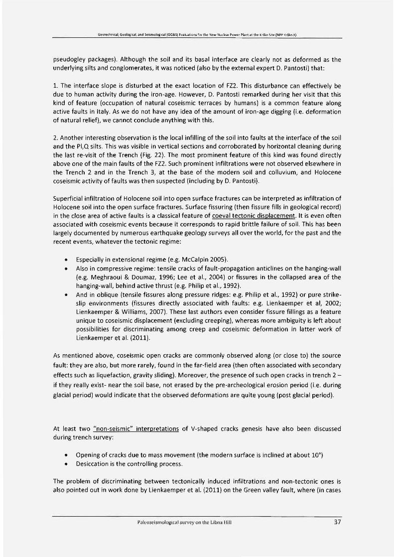
pseudogley packages). Although the soil and its basal interface are c1early not as deformed as theunderlying silts and conglomerates, it was noticed (also by the external expert D. Pantosti) that:
1. The interface slope is disturbed at the exact location of FZ2. This disturbance can effectively bedue to human activity during the iren-age. However, D. Pantosti remarked during her visit that thiskind of feature (occupation of natural coseismic terraces by humans) is a common feature alongactive faults in Italy. As we do not have any idea of the amount of Iren-age digging (i.e. deformationof natural relief), we cannot conclude anything with this.
2. Another interesting observation is the local infilling of the soil into faults at the interface of the soiland the PI,Q silts. This was visible in vertical sections and corroborated by horizontal c1eaning duringthe last re-visit of the Trench (Fig. 22). The most prominent feature of this kind was found directlyabove one of the main faults of the FZ2. Such prominent infiltrations were not observed elsewhere inthe Trench 2 and in the Trench 3, at the base of the modern soil and colluvium, and Holocenecoseismic activity of faults was then suspected (including by D. Pantosti).
Superficial infiltration of Holocene soil into open surface fractures can be interpreted as infiltration ofHolocene soil into the open surface fractures. Surface fissuring (then fissure fills in geological record)in the close area of active faults is a classical feature of coeval tectonic displacement. It is even oftenassociated with coseismic events because it corresponds to rapid brittie failure of soil. This has beenlargely documented by numerous earthquake geology surveys all over the world, for the past and therecent events, whatever the tectonic regime :
• Especially in extensional regime (e.g. McCalpin 2005).• Also in compressive regime: tensile cracks of fault-propagation anticlines on the hanging-wall
(e.g. Meghraoui & Doumaz, 1996; Lee et al., 2004) or fissures in the collapsed area of thehanging-wall, behind active thrust (e.g. Philip et al., 1992).
• And in oblique (tensile fissures along pressure ridges: e.g. Philip et al., 1992) or pure strikeslip environments (fissures directly associated with faults : e.g. Lienkaemper et al, 2002;Lienkaemper & Williams, 2007). These last authors even consider fissure fillings as a featureunique to coseismic displacement (excluding creeping), whereas more ambiguity is left aboutpossibilities for discriminating among creep and coseismic deformation in latter work ofLienkaemper et al. (2011).
As mentioned above, coseismic open cracks are commonly observed along (or close to) the source
fault: they are also, but more rarely , found in the far-field area (then often associated with secondary
effects such as liquefaction, gravity sliding) . Moreover, the presence of such open cracks in trench 2
if they really exist- near the soil base, not erased by the pre-archeological erosion period (i.e. during
glacial period) would indicate that the observed deformations are quite young (post glacial period).
At least two "non-seismic" interpretations of V-shaped cracks genesis have also been discussedduring trench survey:
• Opening of cracks due to mass movement (the modern surface is inclined at about 100)• Desiccation is the controlling process.
The problem of discriminating between tectonically induced infiltrations and non-tectonic ones isalso pointed out in work done by Lienkaemper et al. (2011) on the Green valley fault, where (in cases
Paleoseismological survey on the Libna Hill 37

Geotecbnka l, Geologtcel, and Selsmolcgrcal (GG& S) Evaluanons for the New Nuclear Power Plant at the Krško Site (NPP Kr\ ko II)
similar to ones found in trench 2) the authors hesitated in discriminating between the tectonic andnon-tectonic origin of fissure infills and sand-filled cracks.
Infiltration of modern soil solely in the upper part of faults mav thus be an evidence of fault openingduring a tectonic event (along Libna fault or along an associated fault like Orlica and Artiče faults),during Holocene. To support this interpretation the analysis of the distribution of the total carbon(TaTIC) content in the PI,Qsilt, soil, "residual clay", and joints infill was performed (Appendix 5). Theresult was sought through corroboration of these results with other analytical results (describedabove) yet no conclusive result was obtained, except for the fact that infiltration is not limited only tothe upper part of the faults but reaches app. 1,5 in depth. The high correlation Pearson coefficient(0.88) between TaTic conte nt in the joints infill and the depth under the soil-sediment interfacesupports the hypothesis of infiltration of some soil material into joints infill (Figs. 22, 40, 41).
Field observations show that the material in joints infill is softer; less compacted and couldconsequently be more porous and permeable than the surrounding sediment. Lowered Eh due topercolating water caused color changes in the neighboring sediment (Fig. 37). From that we concludethat water percolates preferably along joints and the increased TaTic content mayaiso origin formpurely "non-tectonic" processes. It is also seen that modern plant roots in both trenches preferablyfollow the joints (Fig. 18, 19, 37) as they prefer softer joint infill material to harder surroundingsediment (not exclusively, though) . The root bioturbation made joints progressively more permeable .However, in conclusion we can say that this analysis cannot prove or reject the hypothesis oninfiltration of the modern soil in the uppermost part of the joins (faults) caused by opening duringHolocene tectonic/seismic event.
3.2.5 Evaluation of displacement along the Libna fault from findings in and near trench 2
Displacement along the NE branch of the fault (FZ 2) is assessed from observations in the Trench andsupported by additional geophysical interpretation (Appendix 4) to be at the order of magnitude ofseveral meters (less than 10 m in the horizontal direction) (Fig. 27). From the trench log it isinterpreted that the main branch mav be the SW (FZ 1) and from the regional geophysics we mavsuspect that there mav be even more deformation accumulated along the whole width of the Libnafault outside the two fault zones mentioned here. Then, Trench 2 alone does not allow estimatingthe total displacement associated to this fault.
According to the current tectonic model (Bavec, ed., 2010), the potential displacement is notdistributed evenly along the whole length of the Libna fault. It is supposed to be concentrated mostlyto differential folding along the Libna fault thus and most deformation should be taken up on theLibna anticline.
Paleoseismological survey on the Libna Hill 38

Geote cbmcal, Geological, and Seismolog tcal (GG&S) EvakJations.for the New Nudear Power Plant at the Krlko SIte INPP Krl ko II)
Fig. 2 7. Disp/ocem en t es/imate o/ang th e Fl2 is bos ed on dip and thickn ess oj the lo vers in the tren ch,
an d th e com bino ti on of GPR and elec tr ic resistivitv survey oj the neorby area.
Paleosei sm ological survey on the Libna Hill 39
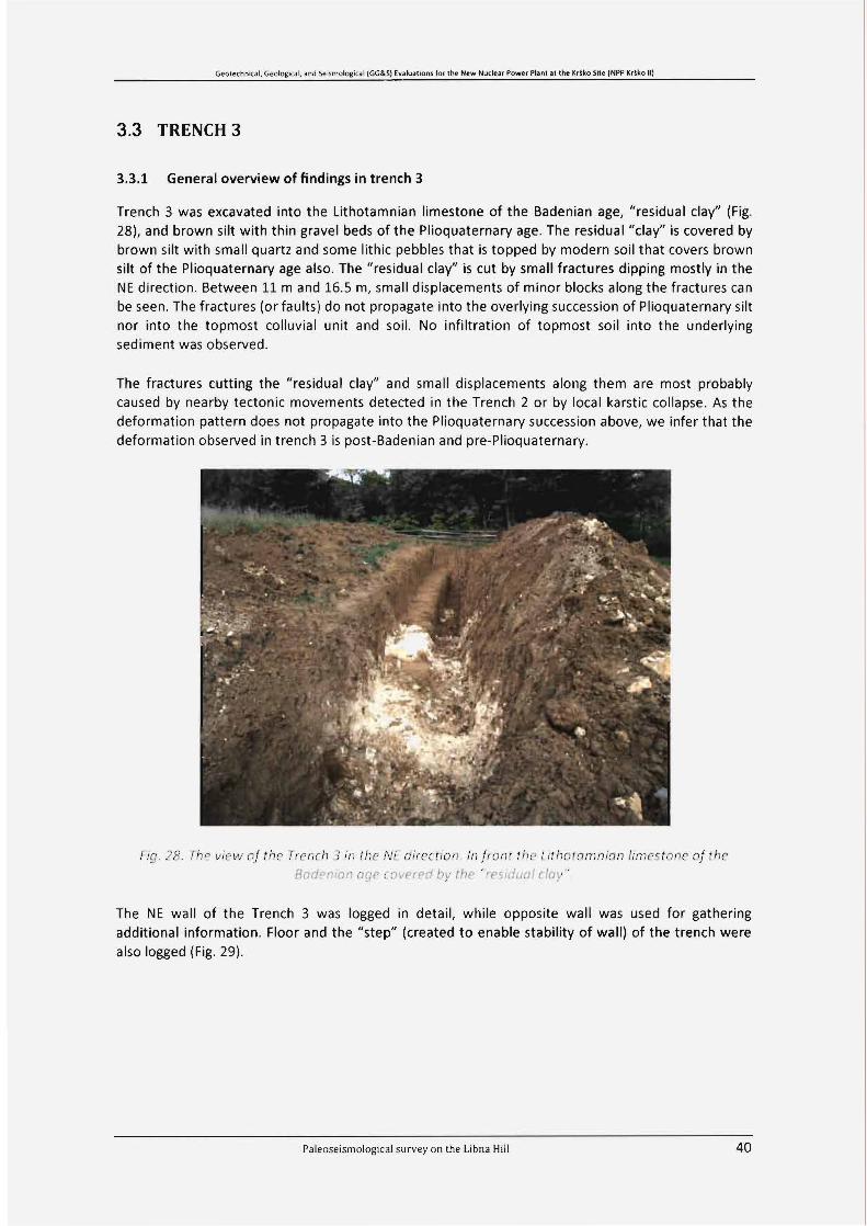
Geo techmcal, Geclo grcal. and Sei!lmological IGG&S) Evakranons for the New Nuclear Power Plant al the K, ~ko Site (NPP Kr1ko II)
3.3 TRENCH 3
3.3.1 Generaloverview of ftndings in trench 3
Trench 3 was excavated into the Lithotamnian limestone of the Badenian age, "residual clay" (Fig.28), and brown silt with thin gravel beds of the Plioquaternary age. The residual "clay" is covered bybrown silt with small quartz and some lithic pebbles that is topped by modern soil that covers brownsilt of the Plioquaternary age also. The "residual clay" is cut by small fractures dipping mostly in theNE direction. Between 11 mand 16.5 m, small displacements of minor blocks along the fractures canbe seen. The fractures (or faults) do not propagate into the overlying succession of Plioquaternary siltnor into the topmost colluvial unit and soil. No infiltration of topmost soil into the underlyingsediment was observed .
The fractures cutting the "res idual clay" and small displacements along them are most probablycaused by nearby tectonic movements detected in the Trench 2 or by local karstic collapse. As thedeformation pattern does not propagate into the Plioquaternary succession above, we infer that thedeformation observed in trench 3 is post-Badenian and pre-Plioquaternary.
Fio , )H 7he view of thr I rcn cb 3 in thr NE direction. In [iont the t itbo tom nion timeston e of theBod enion oge :. :w ('r r d bv the 'Or Silil/ul etov"
The NE wall of the Trench 3 was logged in detail, while opposite wall was used for gatheringadditional information. Floor and the "step" (created to enable stability of wall) of the trench werealso logged (Fig. 29).
Paleose ismological sur vey on the Libna Hill 40

Geo techn k al. Geologrcal , And Sersmotogi cal (GG&S) Evaluatlons for the New Nc cle ar Power Plant at the I(ru,:o Srte (NPP K' ~lco III
NE56"
sw23e"
Irsneh step
fraeture
faull
Qroundsur1ace
sou Iower tnter1ace
l ; ." samples
"
"",1
sili wIth sandy gravel Pla
resldual 'eJay" WIth pebbles
_ res jdual 'day'" Mn ex>'or8d
"
residua l 'd ay' with sili
_ residua l 'c1ay'- LlthoIarmian I.mestone
wall eollapse
"
Fig. 29, The log of tren er. 3.
Paleoseismological survey on the Libn a Hill 41

Gec tecb nk a l, Gectogical. and Seismologtca! (GG&S) Evaluanons for the New Nuclear Power Plant at the Krško Site (NPP Krško II)
3.3.2 Description and interpretation of main sedimentary units
3.3.2.1 The Lithotamnian limestone - Badenian
The Lithotamnian limestone of the Badenian age crops out mostly in the SW part of the Trench 3 andis covered by the "residual day". The Lithotamnian limestone was examined only macroscopically. Itis white, has bindstone and calcarenite structure and among other fossils, contains mostly fragmentsof bivalves, bryozoans and foraminifers encrusted by rhodolites forming red algae (Lithotamnian)(Fig. 30). The Lithotamnian limestone is massive, fractured, weathered and intensively karstified inthe upper contact with the "residual day", forming very uneven, corroded surface with up to 80 cmdeep indentations filled by "residual day". Isolated fragments of very fractured and corrodedlimestone are found in the "residual day" (Fig. 31) (Fig. 32).
rig .30 The Lithotomnian limes/one b in dsi one
Fig. 3 1. In tensivel » kcust ,jied Boder.io n limeston e, JOI nii ru; vel ji u c even , con odeti SUI[o ce inden tat ions
tl/lr>rll.JV 'tIP/es/rluul day ' Til. /IJE w oll o] the trea t u, 14-221r1
Paleoseismological survey on the Libna Hill 42

Geo tech nical, Geo logical, and Seisrnolo gtcal (GG&S)Ivahranons for the New Nudear Power Piani et the Krško Sile (NPP Kriko II)
Fig. 32 tnte nsivelv fra tutea b lock of limes/on e in the " resid uoi etov
3.3.2.2 The "residual day"
The "residual day" lays on the karstified surface of the Badenian Lithotamnian limestone and isoveriaid mostly by up to 1.7 m thick brown silt with small pebbles. The light brown (5YR5/6)"residual day" is mostly massive, somewhere laminated. The laminas are discontinuous, limited inlength, and marked by color differentiations caused by different FeO(OH) concentrations (Fig. 33) orsilt laminas (Fig. 34). Silty patches (ghost sand clasts) of irregular shape and size are unevenlydisposed in the "residual day" (Fig. 35). Smaller silty patches are concentrated in the upper part ofthe "residual day" under brown silt with small pebbles too. The "residual day" is locally marmorisedand contains dark grey patches, most probably colored by Mn oxides and hydroxides.
The "residual day" consists on average of 79 % silt, 20 % day and 1 % sand grain size fraction and hasa main grain size of 0.013 mm . The "residual day" should be named the residual silt according tothese data. In order to distinguish it from the other Iithologic units we refer to it as "residual day".Mineralogical composition is: 17 % quartz, 2 % plagioclase, 43 % muscovite/iIIite, 13 % chiorite, 19 %kaolinite and 7 % goethite (Appendix 5). Muscovite is weathered to poorly crystallized illite.
The silty patches (ghost dasts) contain on average 67 % silt, 23 % sand, 10 % day and are composedof 58 % quartz, 3 % plagioclase, 3 % microcline, 29 % muscovite/illite, 4 % chiorite, 1 % kaolinite, and2 % goethite.
The "residual day" is cut by a network of fractures dipping mostly in the NE direction. The "residualday" is more pale or even grey (N7 - 5B7/1) (Fig. 36, 37) along the colored fractures. Modern rootsfollow the fractures in some places. Between 11 mand 16.5 m. Minor displacements of small blockscan be seen along the fractures (faults) (Fig. 33, 34). Small patches placed along the fractures areconstituted by silt (Fig. 38) containing 90 % silt 3% sand.
Paleoseismological survey on the Libna Hill 43

Geo techruca l, Geolo grcal, and Seumologtcal (GG&S) Evakrat ions tor the New Nuclear Powe-r Plant at the Krika Site (NPP Kd ko Il)
Fig. 33. Laminas marked by co lor diff erentiations co used by diJfe re n t FeO(OH) co ncentra ti ons are cut
by j ro ctures (!o ul ls) o long w hich small blocks are disp loced. The NE wall oj the tre ncti ol 12.8 ol.
Fig. 34 PnI! 0 / (lip ' rOlounl cio}, ' w ll h lir Iwn ltlos ais« cted (]11(1 Ol p!O( (>() ohJ!I('/ sn ui tte: !rCJCfUf("_
The NE wall of tile tren cti 0112.3 m
Palcoseismological survey on the Libna Hill 44

Geo tecbnkal, Geo togical, and Seismologlcal (GG&S)EvakJationsfor tbe New Nuclear Power Piani al the Kriko Site (NPPKrlko II)
Fig. 35. The si lty potclies - qbo: ciosts and weothered lim es /one in Ule "tesiduot [ lav" The NE wall
of the trench at 7.3 m .
Fig. 36 A net O} d ,iJerentlv stickiru; jra ctures olong w Il/eh the "resid ual cia}," is more pale co torea o'even gree nish grey. 7he fra etures dip m ost/y to the NE. St ep of the trencb from 3 rn to 4 171 .
Paleoseismological sur vey on the Libna Hill 45
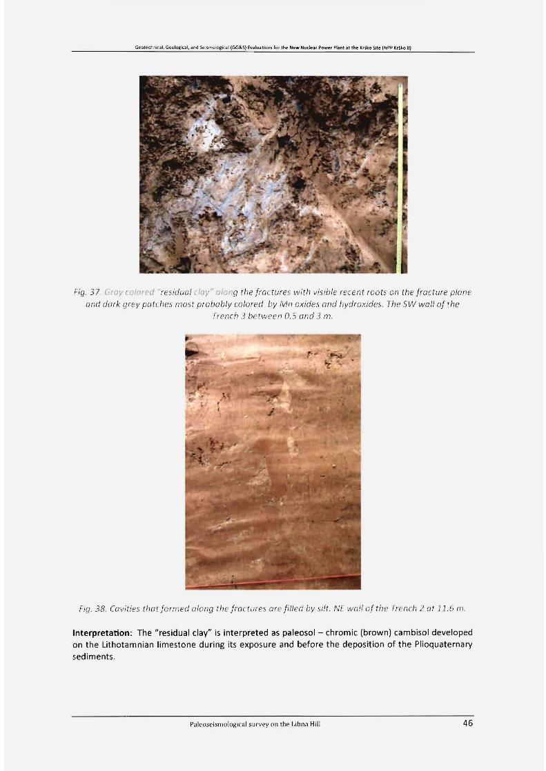
Geotechmc at, Geological, and Setsmclo gjcal (GG&S)Evakrat ions for the New Nud ear Power Piani at the Kriko Sile (NPP Kriko U)
Fig. 37 Gro}' cotored residuo! l lov" atoiu; the [roctures with visihle recent toots on the fro cture pleme
and dark grey potches most probab lv colored bv M I/ oxities aneJ bvdroxides. The SW wa lJ of the
Trench 3 between 0.5 and 3 1'1'1.
!-ig. 38. Covities thot [ort ned oton t; til e [roc tur es are [illed lJy sil i . NE wo lJ of the Trench 2 at j j .ri 1/ 1.
Interpretation: The "residual day" is interpreted as paleosol - chromic (brown) cambisol developedon the Lithotamnian limestone during its exposure and before the deposition of the Plioquaternarysediments.
Paleoseism ological survey on the Libna Hill 46
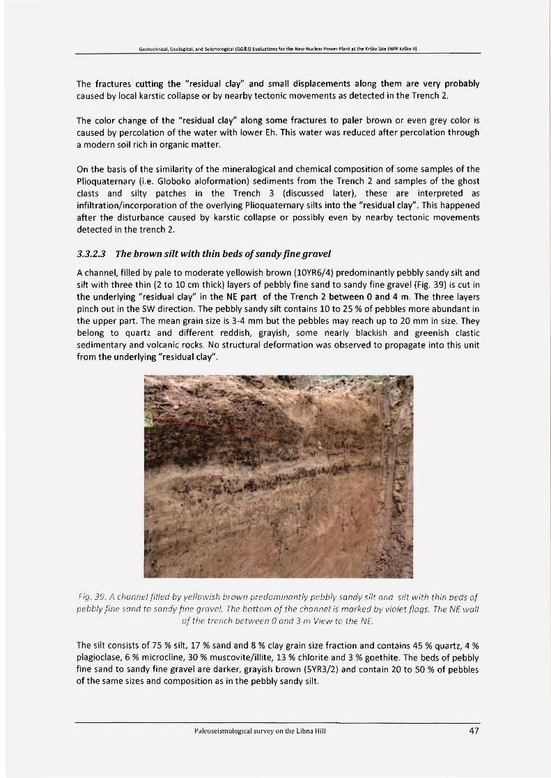
Geotechnkal, Geologic.al, and Seisrnolc glcel (GG&S) Evaluatrons tor the New Nuclear Power Plant at the Krno Site (NPP Kdko II)
The fractures cutting the "residual day" and small displacements along them are very probablycaused by local karstic collapse or by nearby tectonic movements as detected in the Trench 2.
The color change of the "residual day" along some fractures to paler brown or even grey color iscaused by percolation of the water with lower Eh. This water was reduced after percolation througha modern soil rich in organic matter.
On the basis of the similarity of the mineralogical and chemical composition of some samples of thePlioquaternary (Le. Globoko aloformation) sediments from the Trench 2 and samples of the ghostclasts and silty patches in the Trench 3 (discussed later), these are interpreted asinfiltration/incorporation of the overlying Plioquaternary silts into the "residual day" . This happenedafter the disturbance caused by karstic collapse or possibly even by nearby tectonic movementsdetected in the trench 2.
3.3.2.3 The brown silt with thin beds ofsandy fine gravel
A channel, filled by pale to moderate yellowish brown (lOYR6/4) predominantly pebbly sandy silt andsilt with three thin (2 to 10 cm thick) layers of pebbly fine sand to sandy fine gravel (Fig. 39) is cut inthe underlying "residual day" in the NE part of the Trench 2 between O and 4 m. The three layerspinch out in the SW direction. The pebbly sandy silt contains 10 to 25 % of pebbles more abundant inthe upper part . The mean grain size is 3-4 mm but the pebbles mav reach up to 20 mm in size. Theybelong to quartz and different reddish, grayish, some nearly blackish and greenish dasticsedimentary and volcanic rocks. No structural deformation was observed to propagate into this unitfrom the underlying "residual day".
Fig . 39. A cha nnel iiI/ed by vellowish brown pr ed om inon t lv pebbl» sa nd )! si lt and sitt w it h thin beds of
pe bbl» [in e sond to sand)! tin e gra vel . The bo ttom of th e channel is marked bv viol et flog s. The NE w al/
o/ t he trench between O (]nd 3 nJ View to th e NE.
The silt consists of 75 % silt, 17 % sand and 8 % clay grain size fraction and contains 45 % quartz, 4 %plagiaclase, 6 % microcline, 30 % muscovite/iIIite, 13 % chlorite and 3 % goethite. The beds of pebblyfine sand to sandy fine gravel are darker, grayish brown (5YR3/2) and contain 20 to 50 % of pebblesof the same sizes and composition as in the pebbly sandy silt.
Pale oseismological sur vey on th e Libna Hill 47

Geotechncal, Geolo gtcel, and Senmologtcal (GG&S) Evatuano ns for the New Nuclear Pow er Plant at t he Krško SIte (NPP Kri ka II)
Interpretation : By checking surroundings of the trench we found outcrops of the Plioquaternary (Le.Globoko aloFm) sediments a few meters above the upper level of the trench 3. According to this factthe inf ill of the erosive channel is interpreted as beginning of the deposition of the Plioquaternarysediments. This interpretation is also supported by cluster analysis of mineral composition andcombination of mineral and chemical composition of all samples analyzed from the Trenches 2 and 3(Appendix 5).
3.3.2.4 Brown silt with pebbles
The brown (sYRs/6) silt with pebbles is the same color as the underlying "residual day" and hasundulated lower contact .It is Oto 1.2 m thick and is the thickest in the SW part of the trench 3.Thebrown silt is missing between 16 and 17 m. The silt with pebbles contains less than 5 % of pebbles,mainly 2-5 mm grain size that are represented mostly by quartz and less abundant other Iithicpebbles. Their composition is very similar to the composition of the pebbles in the overlyingPlioquaternary sediments . No structural deformation is observed in this unit.
Interpretation: The brown silt with small pebbles is interpreted as a colluvial deposit of the "residualday" and of the overlying Plioquaternary sediments, mostly pebbles.
3.3.2.5 The modern soil
The modern soil covers the brown silt with small pebbles, the brown silt with thin beds of sandy finegravel of the Plioquaternary age and (only in the length of one meter) the "residual day". During theexcavation of the Trench 3 it was removed for safety reasons (to avoid collapse) and will not beanalyzed in more detail. No structural deformation is observed in this unit. The interface with theunderlying sediment was thoroughly checked for possible downward infiltrations (such as observedin trench 2).
3.3.3 Structural observations
The "residual day" is cut by a network of fraetures dipping mostly in the NE direction but with asignificant variability. The fractures are of limited extend and amount of displacement is rarelyobservable. However, some minor normal displacements (at the range of centimeters) of smallblocks can be seen along some faults at the base of the section (Fig. 33, 34), along fault planes withchanging dip angle (Iistric pattern sometimes) . The general pattern of the section, with karstic cavesat the base of a formation affected by faulting with a normal and sometimes "Iistric" pattern, suggestthat gravitational displacements of karstic origin occurred there yet we cannot exdude possiblerelation to tectonic displacement observed in trench 2.
The silty patches (sand dasts) and silt infill of joints induded within the "residual day" mass arecompositionally similar to some samples of PIQ gravel matrix or PIQ sand from the trench 2 and PIQsilt from trench3 (Append ix 5). This lead us to an interpretation that the silty patches (sand dasts)and silt infill of pores (joint) in the " residual day" from the trench 3 are products of infiltration/indusion of the overlying "Globoko" silts into the "residual day", following subsidence beneath thetrench floor by (endo)karstic phenomenon or possibly tectonic movement.
The fraetures and faults do not propagate into the overlying succession of topmost colluvial unit andsoil. No infiltration of topmost soil into the underlying sediment was observed. The deformation alsodoes not propagate into the Plioquaternary succession above, thus we infer that the deformationobserved in trench 3 is post-Badenian (significantly younger of Badenian as the deformed residualday needed time to be formed) and pre-Plioquaternary.
Paleos eismolog ica l survey on the Libn a Hill 48

Geo tec hn kal, Geolo gtce l. and Seismclcgfce l (GG&S) Evaluano ns fo r the New Nuclear Pow er Plan t al the Krško Srte (NPP Krško Il)
3.4 Analysis of granulometric, mineralogical and chemical composition ofsediments in Trenches 2 and 3
3.4.1 Overview of laboratory results and the statistical (cluster) analysis
After the initial interpretations some important questions arose regarding the composition andgenesis of the materials observed. The main purpose of the grain size, mineral and chemical analyseswas to characterize/discriminate of sedimentary units and to analyze the material of joints infill. Allthe details of these analyses are presented as appendix S to this report and only the overview andconclusions are presented here.
It has to be noted that the statistical analysis presented here can only be used as an aid and not asconclusive evidence. The number of analyzed samples may be relatively high for a usualpaleoseismological trench but stili low for a firm statistical analysis.
From the grain size data it can be concluded that most of the samples (34) are granulometricalyc1assified as silt , even those c1assified as residual c1ay (for readability the name "residual c1ay" is keptin this report) in the field . For the residual material of the Badenian limestone it is very unusual tocontain so high portion of silt fraction. The presence of allochtonous, very probable aeolian maternal,as known in many soils of "terra rosa" in the Mediterranean region is suspected. Grain sizedistributions of the PI,O overbank silt and material of joints infill from the T2 are nearly identical,except for the sample of joint infill in FZ2, app. 2 m below surface (L2/27A) that is coarser grained(sandy). Beside the last mentioned sample, five more samples are coarser grained as well: samplesL2/27A and L3/3S are classified as sandy silt; sample L2/10A as silty medium grained sand; samplesL2/2SG, L2/M2 as muddy gravel and sample L2/Ml as gravely muddy sand.
By mineral composition the analyzed samples can be grouped into five c1usters. The largest cluster 1includes majority of samples of the PI,OsiIt, joints (faults) infill and soil. Only one reddish joint infill inthe PI,O sand (Unit 4) is c1assified in the cluster 2 together with samples of "residual clav" and withthe red tectonic jens from the T2. In the cluster 3, samples of "residual c1ay" are grouped includinggrey joint infill within "residual c1ay" from the 13. Samples of silty patches (sand c1asts) in the"residual c1ay" from the 13 and a sample of the PI,O silt from the T2 are enclosed in cluster 4 whilecluster Sincludes samples of gravel matrix, PI,Osand from the T2 and silty joint infill in the "residualc1ay" from the 13.
Very similar group ing of the samples characterized by combining mineral and chemical compositionwas achieved with solution of 7 c1usters by k-mean cluster analysis. Two samples are outstanding andoccupy their own c1usters. The most outstanding is sample of joint infill L2/27A (cluster 4) and to aless degree a sample of PI,O sand L2/10A (cluster 6). Comparing grouping of samples based onmineral composition with grouping based on mineral and chemical composition combined, one cansee that the chemical composition causes the difference. Chemical composition (mostly conte nt ofBa and Th) discriminated in 7-c1uster solution also between c1usters 2 and 3, which are the mostsimilar to each other of all. Cluster 2 encompasses mostly samples of joints (faults) infill and PI,Osiltsfrom the upper step of the T2 while samples from cluster 3 are taken from the PI,O silt from thelower step of the T2, and the Holocene soil. Higher conte nt of Th in Cluster 2, and higher conte nt ofBa in cluster 3 is observed. In the 4 and 6 k-mean solution both c1usters are united (Appendix S). Thesamples of joints (faults) infill from the T2 are not differentiated, but it is obvious that the L2/C3sample (the reddish joint infill in the PI,O sand) differs from the others. The cluster S enclosessamples of silty patches (sand c1asts), silt infill of pores (joints), PI,Osilt from the 13 and gravel matrixfrom the T2. It is interesting that in all cases of cluster analysis samples of silty patches (sand c1asts)and silt infill of joints in the "residual c1ay" from the 13 are c1ustered with some samples of gravel
Paleosei sm ological su rv ey on the Libna Hill 49

Geot ec hmcal. Ge o togkal , a nd Seisrno fogical (GG&SJ Evalu a uo ns fo r the New Nuclea r Pow er Plant at the Krik a Sn e INPP Kd ko III
matrix or PI,Q sand from the T2 and PI,Q silt from 13 (Appendix 5). This leads us to an interpretationthat the silty patches (sand c1asts) and silt infill of pores (joint) in the "residual c1ay" from the 13represent products of infiltration of the overlying PI,Q silts into the "residual c1ay" after disturbancecaused by nearby tectonic movements detected in the Trench 2. The silt laminas in the "residualclav" bounded by fractures mayaiso be interpreted that way. Samples of "residual clav" from 12 andthe ones from the reddish tectonic lens from the fault zone 1 form cluster 7. Samples of "residualc1ay" from the 13 with the grey joint infiII are joined in cluster 1. Note that (L3/34Z) sample of greyjoint infill is c1assified in the 4 and 5 cluster solution together with other samples of joints infill andPI,Qsilts from the upper step of the T2.
Possibility of the Holocene soil infiltrat ion into some jo ints was tested at the IRSN laboratory byadditionally analyzing total carbon (TC) and totalorganic carbon (TaC) in 21 samples. The depthunder the soil-sediment interface (Depth), average (TOT/C) of (TC) analyzed by IRSN and (TOT_C)analyzed by ACME is given ln the Table 4. Comparison of the data of TOT/C and TC from bothlaboratories detected significant difference in five of analyzed samples. Among others, differenceswere within the declared analytical error. TC and TaC chemical analysis showed that nearly allcarbon is in fact organic carbon (TaC). This is also supported by the mineralogical analysis as nocarbonate minerals were found within the analyzed samples .
The k-mean cluster analyses with solut ion of 7 c1usters were run only on the chemical compositiondata analyzed by ACME. The analysis of variance shows that TOT/C is among 17 statistical nonsignificant (p<O.OS) variables . In other words, variances of TOT/C are larger within c1usters thenbetween c1usters. It is also interesting that samples of the Holocene soil, the joints infill from the T2just under the soil, and the grey joint infill (L3/34Z) in the "residual c1ay" from the 13 form their owncluster 1 (Table 3).
Paleoseismological survey on the Libn a Hill 50

Geo tec hnkal. Geoto gjcal, and Seu mclogtca l (GG&S) Evakranons for the New Nucle ar Powe r Plant at the Krško SIte (NPP Kriko Il)
Sample lith./locat. Cluster Distance Case_No
L2/112 joint 1 3,90 18
L2/113 joint 1 3,52 19
L2/114 soil 1 5,92 20
L2/115 soil 1 4,52 21
L2/116 joint 1 4,89 22
l3/34Z joint 1 8,65 26
L2/26A PIQsilt up 2 6,06 9
l2/Cl joint 2 5,85 10
L2/C3 joint 2 8,29 11
L2/C5 joint 2 5,00 12
L2/2SG matrix 2 10,20 15
l3/30 joint 2 6,17 23
L3/36 PIQsilt 2 10,44 28
l2/20 PIOsilt low 3 4,76 5
L2/12A PIOsilt low 3 5,96 6
l2/22A PIOsilt low 3 3,36 7
L2/23A PIQsilt up 3 5,93 8
l2/28A PIOsilt low 3 3,85 14
L2/GMU matrix 3 5,31 16
L2/104 PIOsilt up 3 7,27 17
L2/27A joint 4 0,00 13
L2/10A PIOsand 5 10,71 1
L3/35 sand c\ast 5 10,71 27
l3/31 Resid_Bad 6 5,38 24
L3/340 Resid_Bad 6 5,38 25
l2/15A Resid_Bad 7 5,10 2
L2/16A Resid_Bad 7 4,10 3
l2/18A red tet lens 7 8,56 4
Table 3: Cluste r rnem bers (sampl es) dejined by chernical cornposition and th eir distances from th e
cluste r cente rs
The samples from the T2 in the cluster 1 have also the highest concentrations of TOT/C of allanalyzed samples. Higher concentration of TOT/C than the average for the PIOsilt is detected also inthe reddish joints infill (samples: L2/C3, 105 cm below the modern soil; L2/C5, 225 cm below themodern soil). Plot of TOT/C versus depth was constructed for 24 analyzed samples (Fig. 40). The totalcarbon (TOTIC, which is mostly organic carbon) infiltration along the joins is supported by the scatterplots TOT/Cversus Depth (Fig. 41) and high (0.88) correlation Pearson coefficient.
Paleoseismological survey on the Libna Hill 51

Geotechmc al. Geolog ical, and Seu mologica l (GG&S) [ valuatlons for the New Nudear Power Plant at the Krika Sne (NPP Krika II)
r
50
• L2/24A2/2GA • ) /23 . L2/104•• L ~ , A
L2/25A
L2/ 22,\
~. l 2 /1 2 AL2/21A • L2/ 20
• • L2/C4 U / e 5L2/U . L2/ 27 A
2/C I• • U / 2SA
. L2/ 15A
• L2/IGA• l 2/C3
L2/115•• 12/l14• . l 2/ 1J 2
L2/11 G . l 2/1 13
• R (' ~ ld BJd
• red tcct 10 1 s
_ Ioml
. ~od
. P IQ ~ l l l
0.80.60.4
• L}f ISA
0 .2
o
-50
-100
Eus: -150OOQIO
-200
-250
-300
·350
O
TOT/(%
{ig , 40 Scotter p lo t oj th e TOTjC (%) con ten t in the PIQ ovet bank silt, Ho locen e oii rr esiduo ! etov
und joints in/ill versus th e dep t ]! be low m ode m suil of th e 24 on otvzed sompies.
Paleose ismological survey on the Lihna Hill 52

Geo technk al, Geological, and Seismo logjcal (GG&SIEvaluatians for the-New Nuclear Powe-rPlant at the-Kriko Site INPPKrIka II)
50
O
·50
E · 100us:-Q.~
O ·150
·200
·250
·30 0
• • [ 2/ C4L2/ a " l2/ 27A
/ L2!Cl
•
• • L2 !1122/116 . L2/1l3
• L2/ C3
/
_ joint
l 2/C5-o 0.1 0.2 0. 3 0 .'1 0.5 0.6 0.7 0,8 0.9
TOT/C %
Fig. 41 Scatter plot of th e TOTj C (%) con ten t in the join ts infill ver sus th e dep th below m odern sai/ of 9
ano /yzed sornp /es and their corre to tio n [D epth = -338,11+432,84'x }.
3.4.2 Conclusions from analyzing the mineralogical, granulometric and geochemical compositionof sediments
Two hypotheses were discussed within the team over the genesis of the PI,O silt. One interpretedPIO silt as an alluvial overbank flood plain sediment that was modified by pedogenic and otherprocesses or as being of colluvial origin. On the basis of field observations we support the firsthypothesis , but with laboratory analyses presented here we cannot prove or reject none of the twohypotheses.
The mineralogical and chemical composition of all the PI,Osamples is in full correlation with the grainsize of analyzed samples: gravel matrix groups together, sand groups together and silts groupstogether, respectively. However, two of the main questions asked in this analysis were: 1) is the siltcolluvium and/or 2) is the silt differentiated into two parts, e.g. into lower overbank deposit, andoverlying colluvial cover. In this respect we have to mention a slight differentiation among those siltsamples that lay less than 1 m below the Holocene soil, and those that lay deeper. Namely in one ofthe cluster solutions of chemical analyses, differentiation among the two was identified based mostlyon (small) differences in content of Ba and Th (see above and Appendix 5).
The silty patches (sand c1asts) and silt inf ill of joints in the "residual c1ay" from the Trench 3 arecomposit ionally similar to some samples of PIOgravel matrix or PI,Osand from the Trench 2 and PI,Osilt from the Trench 3.
Grain size dist ributions are nearly ident ical in the PIO silt and in the silt in the jo ints inf ill, except forthe (L2/27A) sample of joint infill from FZ 1, app. 2m below the modern soil that is coarser grained
Paleoseismological survey on the Libna Hill 53

Geo tech nicel. Geologrcal. and Seurnclogrca l (GG&Sl Iveluanons for the New Nucle.ar Power Plant at th (" Kr-iko Sile (NPP Kri ko Il )
(sandy). It is outstanding also in the mineralogical and chemical composition. However, most of thejoints infill silt samples have nearly the same mineral composition as the PIQsilt, matrix of gravely siltand the Holocene soil. The mineralogical composition of the red tectonic lens (L2/17A, L2/18A) andjoint infill (L2/C3) is closer to the "residual clav" of the Trench 2.
The mineralogical and chemical composition similarity between the PIQ silt and the Holocene soil isnot surprising as the PIQsilt was obviously parent material for the soil.
Distribution of the total carbon (TaTIC) content in the PIQ silt, soil, "residual clav" and joints infillversus depth under the soil-sediment interface (Depth) and the scatter plot of the TaTIC conte nt inthe joints infill versus the depth under the soil-sediment interface were used to test the hypothesisof possibility of modern soil infiltration into some joints infill at depth (Fig. 41). The high correlationPearson coefficient (0.88) between TaTiC content in the joints infill and the depth under the soilsediment interface supports the hypothesis of infiltration of some soil material into joints infill.According to field observations, plant root bioturbation, and color changes it is obvious that waterpercolates along joints. After water percolate through soil its Eh is getting lowe r that influences theneighbor sediment (color changes), infiltration of some material from the soil above can be expected.However, this analysis cannot prove or reject the hypothesis on infiltration of modern soil in theuppermost part of the joins (faults) caused by opening during Holocene tectonic event.
The "residual clav" on the Badenian limestone mineralogicaly and chemically slightly differs amongthe trenches 2 and 3. The main difference is in the content of kaolin ite. It is present only in the"residual clav" in the Trench 3.
The color of the "residual clav" changes from moderate brown to paler brown or even greyalongjoints. We interpret that this is caused by percolation of water with lower Eh along joints. This waterwas reduced after percolation through amodem soil. The mineralogical composition of these jointsinfill did not change and is very similar to the " residual clav", but some slight changes in chemicalcomposition are observed .
It is unusual that the residual material of the Badenian limestone contains so large portion of siltfraction . We suspect the presence of allochtonous, very probable aeolian matemal, as it is known inmany soils of "terra rossa" in the Mediterranean region.
Paleos eismo log ica l sur vey o n the Libna Hill 54

Geotechnkal, Geclogjcal , and Setsmologica l (GG&S) Evaleauora for the New Nuclear Power Ptant at t he Kri ke Site (NPP Krike Il)
4 POTENTIAL IMPLICATIONS OF NEW FINDINGS FOR SEISMICHAZARD AND CAPABLE FAULT ISSUES
From observations on the Libna fault, the following issue arise that implies a need for furtherdarifications:
• The Libna fault mayaiso be described as a capable fault and additional data and/or analysisare required because some important issues for the assessment of the potential impacts ofthe fault are stili open. Should the Libna fault be considered a seismic source in seismichazard assessment?
4.1 LIBNA FAULT AS A CAPABLE FAULT
Libna fault is not an important structural element of the Krško basin. Moreover, from its geomorphicexpression and its mapped length, it seems unlikely that it is a fault that is capable of generatingearthquakes large enough to produce surface fault rupture. However, recent findings in the trench#2 at the Libna Hill indicate that the Libna fault mav be described as capable if capability is defined inline with Safety guide SSG-9 (IAEA, 2010; where capability is not necessarily related to earthquakeson the fault of concern) and if the lower age-estimates of PI,Q formation are taken as relevant;because:
• The geologic buildup of the Libna hill is affected by strike -slip faulting, induding deformationof the Globoko PIQgravels and the overlying silts. Deformation is significant.
• The trench survey revealed a structural pattern in PIQ sediments (muitipie fault traces doseto the surface, complex branching pattern leading to an anastomosing geometry) that mavbe indicative of coseismic and recurrent displacements.
• One of more plausible interpretations is also that the observations are consistent with PostMousterien fault ing on FZ1 (if indusion of the Mousterien tool in the silty formation andwithin the FZ1 is interpreted as coeval) and also with Holocene coseismic deformation (ifopen cracks in FZ2 infilled by the organic soil are interpreted as coseismic).
The map locates the inferred capable fault inside the Sava plain into app. 200 m wide band, with itsaxis at only 250 meters and 500 meters (approximately) east of the eastern and western site fences,respectively. The capable fault then is not exactly crossing the eastern site project. Following the NRCregulation, we recommend investigating thoroughly especially nature and amount of displacement(kinematics, slip per event and cumulated sllp), slip rate, estimation of recurrence interval andelapsed time since last event. Considering the strike-slip kinematics of the fault, we are aware thatsome of these tasks will be difficult to investigate and the results mav not be condusive, especiallythe data dealing with fault displacement and the age of the sediments .
We suggest that the location and geometry of faults along with the details of the spatial pattern ofthe fault zone (which mav be important as they mav define the part icular locations where faultdisplacement mav be expected) should be re-addressed. This latter topic is here particularlysignificant because of the short distance between the fault and the sites.
Paleoseism ological survey on the Libna Hill 55
Geot ecbrucal. Geolo gtcal, and Setsrnolo grcal (GG&S) Ivalua non s for the New Nuclear Power Plant at t he Krsko $It(' IN PP Kri ka II)
4.2 LIBNA FAULT AS A SECONDARY STRUCTURE, ACTIVATED BYA NEARBYSEISMIC SOURCE?
The external expert Daniela Pantosti suggests that the observed infiltrations of soil into theunderlying sediment are infill of open cracks (see the trench 2 part of the report and Appendix 1),and that they could be secondary coseismic features due to a seismic event generated by anothernearby fault. Additional actions are required to explore this possibility, the known fault sources thatcould be such "primary structures" are the Grlica and Artiče faults . The structural relat ion betweenthe Libna fault and th is nearby source fault (referring to the point (c) of the IAEA regulation guide)should then be explored.
4.3 LIBNA FAULT AS A SOURCE IN SEISMIC MOTION CALCULATION?
The Libna fault has so far been excluded from the seismogenic sources in PSHA, because there wasno c1ustering of seismicity around it and its geometry could not have been associated with M>6events, which are already included in the background seismicity. This position was based on theknown length of the Libna fault (5 km) with its northern termination against the Grlica fault, and thesouthern termination underneath the Quaternary infill of the Krško basin against the inferred seriesof the so called "Balaton" faults , the latter being based on the geophysical data and the overalltectonic model.
From the new observations in the trench, we can argue that the width of the deformed zone is about30 meters and it mayaiso be larger, according to its "geophysical signature " (200 m.). According toscale relations (Scholz, 1997; Childs et al., 2009), such a large deformed zone mav be associated witha cumulated slip ranging between 30 and 300 m. By applying another scale relation betweencumulated slip and length of fault (Kim & Sanderson, 2005), the theoretical range of such a faultlength should then be between 3 and 30 km. The conclusion from these relations is that the Libnafault length of 5 km is completely consistent with the available data, but a scenario with a longerfault is also possible (see the paragraph below).
Considering that the Libna fault is an active fault (affecting Plioquaternary and potentially also morerecent layers), we conclude that the scenario with a 10 km long fault (continuation int o the Gorjancimts. into Malence fault and ending against the Čatež - Brvi structural zone; see Geology report of thisproject; Bavec, ed., 2010) cannot be conclusively discarded Thus, a consideration has to be made if itshould be included in seismotecton ic models in the lack of any discarding data, to comply with thephilosophy of a conservative approach . The importance (weight) of such an option should then ofcourse account for discarding the current tectonic model. However, we do not see the potentialsolution in simply adding the Libna fault into the current seismotectonic model as an option withsignificant probability. If attempts will be made in that direction, it should also be considered that thewhole set of faults belonging to the same group as Libna (Sromljica, Močnik 1&2, Gabrnica, Trsnjak,Dramlja ...) acts as a set of seismic sources of scattered seismicity, or a new tectonic andseismotectonic model will have to be built.
A possible solution to better constrain the geometry of the Libna fault south of its currenttermination is bya series of high resolution seismic lines across the continuation of its known trace .
ln case of re-addressing the current tectonic model by additional investigations on the Libna fault ,also a possibility of investigating its potential continuation across the Grlica fault should beconsidered . Current tectonic model (based on the regional geological knowledge and in this
Paleoseism ological survey on the Libna Hill 56

Gectechn ical. Geologrcal. and Setsrnological (GG&SI Evalua no ns for the New Nuclear Pow er Plan t at the Krško Site (NPP Krško II)
particular part on the 1:5.000 non-reviewed manuscript geologic map) does not support such asolution, however the small alluvial plane disables the direct observations at the contact of the twofaults.
4.4 ADDRESSING THE AMBIGUITIES
As previously mentioned with we recommend investigating the site vicinity for the capable fault issueeven if conclusive results cannot be guaranteed beforehand.
1. In order to further assess the fault slip rate, we propose to continue the electrical mappingaround trench 2 on the Libna hill. This approach gave encouraging results in 2009 and it willavoid to further excavation in the archeologically protected area.
2. We propose new trench(es) at the Libna foothills (not archeologically protected). With newtrench(es) across Libna fault, we mav hope to :
a. Evaluate the activity of the fault in young colluvial deposits . By trenching, in thelower terrace that lies above the Sava plain, we mav get the opportunity of cuttingsuch young colluvium and to validate (or not) the different interpretations arisingfrom the trench 2. The 2009 geophysical campaign (Mušič, 2009) revealed apotentially interesting site for trenching across the fault, with a clear NW-SE electricanomaly in the continuation of the trench 2 fault segment at the lowermost terracesin the southern foothills of the Libna hill.
b. Examine the coseismic or aseismic character of the fault. It has not been completelypossible in the excavated trench and there is no guarantee that new trenches willhelp but, as mentioned by Mc Calpin (2009), "the degree to which coseismic foult slipcan be distinguished from interseismic slip (creep) depends not only on the proportionof coseismic (morphogenic) to nonseismic slip but (as with the preservation of allpaleoseismic evidence) on the relative rates of local processes." So, two trenches in avery close perimeter can give drastically different information (e.g. Baize et al.,2010).
3. Concerning the potential continuation of the fault, we suggest to perform new highresolution seismic survey south of the Sava river (southern continuation of the Libna fault)and to carry out a morphotectonic analysis north of the Orlica fault (northern continuation) .
4. There is no known absolute dating method that would guarantee (reliable) precise age datingof the deformed sediments in trench 2 on Libna and consequently the age of deformation.The age of deformation mav be better constrained though if addressed by an extensivedating campaign in the Krško basin; dating all terrestrial formations; from PI,Qto most recentones by application of all available dating methods (u-series, cosmogenic nuclides exposuredating, OSL and ESR burial dating , radiocarbon ...).
As said, the tasks listed above are extensive and the results mav not be conclusive. For that, aconsideration can be made by the client to first evaluate a potential impact of the fault to thesite by application of Probabilistic fault displacement hazard analysis (PFDHA) and only thento take a final decision on further field investigations.
Paleoseism ological survey on the Libna Hill 57
Geote chmcal. Geologcal. and Sersrnolcg tcal (GG&S) Evaluancns for the New Nuclear Powe r Pian i at the Krško SIte INPP Krlko III
5 CONCLUSIONS
The investigations performed by the consortium on the Libna fault, located near the two potentialNPP II sites, show:
• The geologic buildup of the Libna hill is affected by strike-slip faulting, including deformation ofthe Globoko PI,Qgravels and the overlying silts. Deformation is significant.
• In lack of more constraining age - dates and other geologic information, the Libna fault should beconsidered capable if capability is defined in line with Safety guide SSG-9 (IAEA, 2010; thatdefines the recent activity of the fault by investigating its past activity as far back as to Plioceneand does not condition capability with seismic potential of the fault.)
• The structural pattern observed in the PIQsediments mayaiso be indicative of coseismic andrecurrent displacements.
Results were not conclusive regarding two topies:
• The data does not allow distinguishing between the two alternative interpretations of theobserved features in the trenches: the aseismic and the coseismic one.
• Comparison of various age dates of the Plio-Quaternary sediments in the area gives inconsistentresults, which sheds doubts about the age of displacement along the Libna fault .
Additional investigations and analysis proposed in this report mav lead to a better assessment of thepotential impact of displacement along the Libna fault.
Concerning the assessment of the potential impact of the Libna fault to the two potential sites ofconcern the consortium has not found agreement on the consequences of the findings .
Paleoseismological survey on the Libna Hill 58

Geotechmcal. Geological , and Seismo logical (GG&S) Evaleanons for the New Nuclear Power Plant at the Kr!ko SIte (NPP Krške II)
6 REFERENCES
Baize et al. 2010: Paleoearthquake evidences along the Pallatanga Fault (Ecuador), a segment of theDolores- Guayaquil-Megashear. ESC 32nd General Assembly, Montpellier (France), 6-7 september.
Bavec, M. 2000: Poročilo o določanju starosti kvartarnih sedimentov v Krški kotlini z metodotermoluminescence (Tl) in optično stimulirane luminescence (OSL) . Projektna naloga: Neotektonskeraziskave na območju JE Krško. Naročnik Uprava RS za jedrsko varnost. - Tipkano poročilo. Geološki
zavod Slovenije.
Bavec, M. (ed.) 2008: Paleoseismological investigations of the Libna fault. Trench in Stari Grad. Project report for Geotechnical, Geological, and Seismological (GG&S) Evaluations for the NewNuclear Power Plant at the Krško Site (NPP Krško II); tasks 4.3.1.c, 4.3.1.c1, 4.3.1.d; 22pp, 5
appendices .
Bavec, M., Rižnar, l ., Jež, J., Novak, M. 2008: Geološka spremljava v okviru varstva naravne dediščine strukturno tektonske značilnosti na območju trase in spremljajočih objektov na AC Vrba - Črnivec
(Peračica) . ) - Tipkano poročilo, 64 str. Geološki zavod Slovenije.
Bavec, M . (ed.) 2010 : Geotechnical, geological and seismological (GG&S) evaluations for the newnuclear power plant at the Krško site (NPP Krško II), Geology : phase 1 : revision 1. ljubljana :Geological Survey of Slovenia, 2010.178 pp .
Childs et al. 2009: A geometric model of fault zone and fault rock thickness variations. Journal ofStructural Geology, 31,117-127.
Grad, K., Ferjančič, L., 1974: Osnovna geološka karta SFRJ, list Kranj, 1:100.000. Zvezni geološki zavod,
Beograd
IAEA 2003 : Site Evaluation for Nuclear Installations", IAEA SAFETY STANDARDS SERIES, SAFETYREQUIREMENTS No. NS-R-3, Vienna, INTERNATIONALATOMIC ENERGY AGENCY.
IAEA 2010: Seismic Hazards in Site Evaluation for Nuclear Installations", IAEA SAFETY STANDARDSSERIES, Specific Safety Guide No. SSG-9, Vienna, INTERNATIONAL ATOMIC ENERGY AGENCY.
Kim and Sanderson . 2005: The relationsh ip between displacement and length of faults: areview.Earth-Science Reviews, 68, 317-334.
l.ai, Z. P. 2010: Chronology and the upper dating limit for loess samples from luochuan section in theChinese loess Plateau using quartz OSl SAR protocol. - Journal of Asian Earth Sciences 37 (2010)176-185.
lee, J. C, Rubin, C, Mueller, K., Chen, Y. G., Chan, Y. C, Sieh, K., Chu, H. T., and Chen, W. S. 2004.Quantitative analysis of movement along an earthquake thrust scarp: A case study of averticalexposure of the 1999 surface rupture of the Chelungpu fault at Wufeng, western Taiwan. J. AsianEarth ScL 23, 263-273.
Lienkaemper, J. J., Dawson, T. E., Personlus, S. F., Seitz, G. G., Reidy, L. M ., and Schwartz, D. P. 2002 . Arecord of large earthquakes on the southern Hayward fault for the past 500 years. Bull. Seis. Soc. Am.92(7) , 2637-2658.
Paleosei sm ological su rvey on the Libna Hill 59

Geo techmcal, Geologkal, and Setsmclogical (GG&S) Evalua non s for the New Nude ar Power Plant al the Krško Site fNPP K r ~ ko II)
Lienkaemper and Williams 2007. A record of large earthquakes on the southern Hayward fault forthe past 1800 years. Bull. Seis. Soc. Am., 97, 1803-1819.
Lienkaemper, J.J., Sickler, R.R., Brown, J. and Baldwin, J.N. 2011: A Record of Large Earthquakes onthe Green Valley Fault for the Past Millennium. - Bull. Seis. Soc. Am., Submitted;ftp:!/ehzftp.wr.usgs.gov/jlienk/gvf/BSSA-D-11-00nnn-esu pp/BSSA-D-11-00nnn-esupp.html.
Lowick, S. E., Preusser, F. and Winkle, A. G. 2010: Investigating quartz optically stimulatedluminescence doseeresponse curves at high doses. - Radiation Measurements 45, 975-984.
Lowick, S. E., Preusser, F., Pini, R. and Ravazzi, C 201Ob: Underestirnatlon of fine grain quartz OSLdating towards the Eemian: Comparison with palynostratigraphy from Azzano Decimo, northeasternItaly. - Quaternary Geochronology 5, 583-590
Lowick, S. E. and Preusser, F. 2011: Investigating age underestimation in the high dose region ofoptically stimulated luminescence using fine grain quartz. - Quaternary Geochronology 6, 33-41.
McCalpin, J. P. (2005a). Late Quaternary activity of the Pajarito fault, Rio Grande rift of northern NewMexico, USA. Tectonophys. 408, 213-236.
McCalpin. 2009: Paleoseismology. Academic Press, 629 pages.
Meghraou i and Doumaz 1996. Earthquake -induced flooding and paleoseismicity of the El Asnam(Algeria) fault -related fold . J. Geophys. Res., 101, 17,617 -17,644.
Miall. 1977: Areview of the braided river depositional environment : Earth Science Review, 13, 1-62.
Mušič 2009: Report on ground penetrating radar and resistivity survey. Libna, Oct. 2009. - Internalreport, Gearh d.o.o
Philip, H., Rogozhin, E., Cisternas, A., Bousquet, J. C, Borisov, B., and Karakhanian, A. (1992) . TheArmenian earthquake of 1988 December 7: Faulting and folding, neotectonics and paleoseismicity .Geophys. J. Int. 110, 141-158.
PilIer, W.E., Mathias Harzhauser, M . and Mandič, 0 .2007: Miocene Central Paratethys stratigraphycurrent status and future directions. Stratigraphy, 7,151-168.
Premru, U., 1983: Osnovna geološka karta SFRJ, list Ljubljana, 1:100.000. Zvezni geološki zavod,Beograd
Rakic, M., P. Steji č , P. and Simonovi č , S. 2002: Palaeogeography of Southeasteren Part of PannonianBasin During Pliocene and Quaternary. - Geologica Charpatica 53, Special Issue. Proceedings of XVI I.Congress of Carpathian-Balkan Geological Association Bratislava.
Rižnar, I., Koler, B. & Bavec, M. 2005: Identifikacija potencialno aktivnih struktur vzdolž reke Save napodlagi topografskih podatkov in podatkov nivelmanskega vlaka. (Ident ification of potentially activestructures along the Sava River using topographic, and leveling line data) . - Geologija 48/1, 107-116,Ljubljana.
Scholz. 1997: Scaling properties of faults and their populations. Int . J. Rock Mech . & Min . Sci, 34, 3-4.
Paleoseism ological survey on the Libna Hill 60
Geotecbrncal. Geologtcal, and Setsmclogtcal (GG&Sj Evaluanons for the New Nucfear Power Plant at the Krško SIte (NPP Krško II)
Swan, H. B., Hanson, K.L., Poljak, M., Živčič, M. & Gosar, A. 2004: Revised Seismotectonic Model ofthe Krško Basin, Part 1, PRS-NEK 2.7.1 rev. 1. prepared for Nuclear Power Plant Krško, Vrbina 12,Krško, Slovenia; by Geomatrix Consultants, Inc, Oakland, California, USA; in cooperation withUniversity of Ljubljana, Faculty of Civil and Geodetie Engineering Institute of Structural Engineering,Environmental Agency of the Republic of Slovenia, Office of Seismology; and Geological Survey ofSlovenia .
Šikic, K., Baseh, O., Šimunič, A., 1979: Tumač za list Zagreb L 33-78. Osnovna geološka karta SFRJ1:100.000. Savezni geološki zavod, Beograd.
Verbič, T., 1995, Kvartarni sedimenti v vzhodnem delu Krške kotline: Unpublished report, št. dok.ŠGGS7, 248 p.
Verbič, T. 2004: Stratigrafija kvartarja in neotektonika vzhodnega dela Krške kotline. 1. del:stratigrafija. (Quaternary stratigraphy and neotectonics of the Eastern Krško Basin. Part 1:Stratigraphy). - Razprave IV Razreda SAZU XLV-3, 171-225, Ljubljana (Abstract in English).
Verbič, T., 2005: Stratigrafija kvartarja in neotektonika vzhodnega dela Krške kotline. 2. del:neotektonika. (Quaternary stratigraphy and neotectonics of the eastern Krško basin. Part 2:Neotectonics.) - Razprave IV. Razreda Sazu, vol. XLVI-1, 171-216, Uubljana (Abstract in English).
Wells and Coppersmith 1994: New empirical relationships among magnitude, rupture length, rupturewidth, rupture area and surface displacement. Bull. Seism. Soc. America, 84, 974-1002.
Paleoseismological survey on the Libna Hill 61


![GENEZA LEŽIŠTA LJUBIJA - pmf.unizg.hr1].pdf · Geološki položaj (I) After Pamic (1998) Ophiolites associated with genetically related sedimentary formations - open Tethys Sedimentary,](https://static.fdocuments.in/doc/165x107/5e188ca0f33cac47a06af0ca/geneza-leita-ljubija-pmfunizghr-1pdf-geoloki-poloaj-i-after-pamic.jpg)