i i ’ :, ‘ * ‘ , .,‘ . , - Digital Library/67531/metadc60453/m2/1/high... · General Motors...
20
J Ai ,_. ! (LT. \ ~ r \, ” i i ’ :, ‘* ‘ , / .,‘ . , .. , i ;_ ,’ \ - \ -, ,’
Transcript of i i ’ :, ‘ * ‘ , .,‘ . , - Digital Library/67531/metadc60453/m2/1/high... · General Motors...

J Ai ,_.
! (LT. \ ~ r \, ” i i ’
:, ‘* ‘,
/ .,‘. ,
.. ,
i ;_
,’
\
-
\ -, ,’
TECH LIBRARY KAFB, Nn;r
Ilnlllu~l~Illl~ll~ll~lull~llll lllA3&3
REPORT 1092
FLIGHT INVESTIGATION OF THE EFFECT OF CONTROL CENTERING SPRINGS ON THE APPARENT SPIRAL
STABILITY OF A PERSONAL-OWNER AIRPLANE
By JOHN P. CAMPBELL, PAUL A. HUNTER, DONALD E. HEWES. and JAMES B. WHITTEN
Langley Aeronautical Laboratory Langley Field, Va.
- I
National Advisory Committee for Aeronautics Beadquurters, 1724 F Street NW., Washington 25, D. C.
Created by act of Congress approved March 3, 1915, for the supervision and direction of the scientific study of the problems of flight (U. S. Code, title 50, sec. 151). Its membership was increased from 12 to 15 by act approved March 2,1929, and to 17 by act approved May 25,1948. The members are appointed by the President, and serve as such without compensation.
JEROME C. HUNSAKER, SC. D., Massachusetts Institute of Technology, Chairman
ALEXANDER WETMORE, SC. D., Secretary, Smithsonian Institution, Vice Chairman
ALLEN V. ASTJN, PH. D., Director, National Bureau of Standards. DETLEV W. BRONK, PH. D., President, Johns Hopkins Univer-
sity. THOMAS S. COMBS, Rear Admiral, United States Navy, Chief of
Bureau of Aeronautics. LAURENCE C. CRAIGIE, Lieutenant General, United States Air
Force, Deputy Chief of Staff (Development). HON. THOMAS W. S. DAVIS, Assistant Secretary of Commerce. JAMES H. DOOLITTLE, SC. D., Vice President, Shell Oil Co. MATTHIAS B. GARDNER, Vice Admiral, United States Navy,
Deputy Chief of Naval Operations (Air). R. M. HAZEN, B. S., Director of Engineering, Allison Division,
General Motors Corp.
WILLIAM LITTLEWOOD, M. E., Vice President, Engineering, American Airlines, Inc.
HON. DONALD W. NYROP, Chairman, Civil Aeronautics Board. DONALD L. PUTT, Major General, United States Air Force,
Vice Commander, Air Research and Development Command. ARTHUR E. RAYMOND, SC. D., Vice President, Engineering,
Douglas Aircraft Co., Inc. FRANCIS W. REICHELDERFER, SC. D., Chief, United States
Weather Bureau. HON. WALTER G. WHITMAN, Chairman, Research and Develop-
ment Board, Department of Defense. THEODORE e. WRIGHT, SC. D., Vice President for Research,
Cornell University.
HUGH L. DRYDEN, PH. D., Director JOHN F. VICTORY, LL. D., Executive Secretary
JOHN W. CROWLEY, JR., B. S., Associate Director for Research E. H. CHAMBERLIN, Executive Ojicer
HENRY J. E. REID, D. Eng., Director, Langley Aeronautical Laboratory, Langley Field, Va.
SMITH J. DEFRANCE, LL. D., Director, Ames Aeronautical Laboratory, Moffett Field, Calif.
EDWARD R. SHARP, SC. D., Director, Lewis Flight Propulsion Laboratory, Cleveland Airport, Cleveland, Ohio
LANGLEY AERONAUTICAL LABORATORY, Langley Field Va.
AMES AERONAUTICAL LABORATORY, Moffett Field, Calif.
LEWIS FLIGHT PROPULSION LABORATQRY, Cleveland Airport, Cleveland, Ohio
Conduct, under unified control, for all agencies, of scientific research on the fundamental problems of jlight
II

REPORT 1092
FLIGHT INVESTIGATION OF THE EFFECT OF CONTROL CENTERING SPRINGS ON THE APPARENT SPIRAL STABILITY OF A PERSONAL-OWNER AIRPLANE l
By JOHN P. CAMPBELL, PAUL A. HUNTER, DONALD E. HEWES, and JANES B. WHITTEN
.
SUMMARY
A sight investigation has been conducted on a typical high- wing personal-owner airplane to determine the eJect of control centering springs on apparent spiral stability. Apparent spiral stability is the term used herein to described the spiraling tend- encies qf an airplane in uncontrolled flight as ajected both by the true spiral stability of the perfectly trimmed airplane and by out-of-trim control settings. Centering springs were used in both the aileron and rudder control systems to provide both a positive centering action and a means of trimming the airplane. The springs were preloaded so that when they were moved through neutral they produced a nonlinear force gradient su$icient to overcome the friction in the control system and to produce the forces required to hold the control sztrface at the proper setting for trim. The aileron and rudder control surfaces did not have trim tabs that could be adjusted in sight.
Although the airplane was shown to be spirally stable at air- speeds above approximately 90 miles per hour with the controls held in the trim position, it appeared to be spirally unstable with controls free and with the centering springs disengaged because of the moments produced by out-of-trim control positions. After an abrupt rudder kick and release with the centering springs disengaged, the airplane appeared to diverge in the direction of the rudder kick because friction prevented the rudder from centering. With the centering springs engaged to hold the controls in the exact trim positions, however, the airplane quickly returned to straight and level flight after a rudder kick and would$y ‘(hands of’ for inde$nite periods of time without getting into a dangerous attitude, at least, in the smooth or moderately rough air in which all the tests were made. An indication that the airplane might not jty satisfactorily “hands of7 in very rough air, however, was obtained from results of attempted recoveries from large angles of bank with the elevator f ree. These results showed that, because of the eject of airspeed on lateral and directional trim, satisfactory recoveries could be obtained only by keeping the airspeed essentially constant. These results also indicate that in order to get completely satis-
factory results with control centering springs it till probably be necessary to minimize lateral-directional trim chtinges due to changes in airspeed, power, and fuel loading and to increase the
true spiral stability of the airplane. The eject of the centering springs on the aileron control-force characteristics was not con- sidered objectionable by the pilots since the breakout force (friction plus spring preload) was relatively small (approx. 3.5-lb wheel force). The rudder force characteristics, however, were considered objectionable because the excessive friction in the rudder control system required the use of a large preload and consequently resulted in a large breakout force (approx. 22-lb pedal force).
INTRODUCTION
During the last few years there has been an increasing amount of interest in improving the spiral stability of personal-owner aircraft. One goal has been to have the air- plane fly “hands off” for reasonable periods of time without large changes in heading so that the pilot is not required to control the airplane continually and can devote adequate time to navigation problems. Another goal has been to have the airplane fly safely “hands off” for indefinite periods so that when the pilot is caught in “blind-flying” conditions, he can safely release the controls and will not have to depend on his sense of orientation to keep the airplane in a safe attitude. The unreliabilit,y of the pilot’s sense of orienta- tion is demonstrated very clearly in the flight test results reported in reference 1.
A recent study by the National Advisory Committee for Aeronautics to determine how the spiral stability of personal- owner airplanes can be improved (reference 2) has made clearer a point which has been recognized for some time- that many light airplanes (particularly high-wing designs) are inherently spirally stable in the cruising condition even though they do seem to show unstable spiral tendencies in flight. The two reasons for this apparent spiral instability are: First, a lack of means of trimming the airplane in flight makes it impossible for many light airplanes to ever be perfectly trimmed for straight wing-level flight; and, second, whether or not the airplane has means for trimming, the friction usually present in most light-airplane control systems makes maintaining the same trimmed condition indefinitely difEicult or even impossible because friction prevents the control surface from centering after a deflection.
1 Supersedes NACA TN 2413, “Flight Investfgstion of the Effect of Control Centering Springs on the Apparent Spiral Stability of a Personal-Ommer Airplane” by John P. Campbell, Paul A. Hunter, Donald E. Hems, and James B. Whitten. 1961.
1

2 REPORT 1092-NATIONAL ADVISORY COMMITTEE FOR AERONAUTICS
Therefore, if an inherentily spirally stable light airplane (most high-wing designs and probably low-wing designs with adequate wing dihedral) is provided with means for trimming the ailerons and rudder and if the friction in the control system is reduced to an extremely low value, the airplane might fly itself satisfactorily. One of the greatest difficulties appears to be the reduction of the control-syst;em friction to a negligible amount, because even a small amount of friction will cause trouble. One method suggested in reference 2 for obviating the requirement for negligible friction is to use preloaded control centering springs that have a nonlinear force gradient through neutral deflection and, thereby, provide a positive centering action despite friction in the control system. (See fig. 1.) Centering springs of this type also afford a simple m.eans of trimming the airplane since enough additional preload can be provided to product the forces required to hold the surface at the proper setting for trim. If the additional preload required for trimming is large, however, the control forces are likely to be objection- ably high.
In order to determine the effect on apparent spiral stability of a centering device of this type, a flight investigation has been made with a typical high-wing personal-owner airplane equipped with centering springs in both the aileron and rudder control systems. Flight tests were made with the aileron and rudder springs both engaged, with each spring engaged singly, and with both springs disengaged. Records were obtained of the uncontrolled lateral motions of the airplane starting from straight and level flight and from turns and also following abrupt rudder kicks. Most of the flights were made at speeds from 140 to 150 miles per hour, but a few flights were made at 120 and 90 miles per hour. The theoretical spiral stability of the airplane was calculated for correlation with the flight test results.
Control defleciion
FIGURE I.-Variation of spring centering force with control deflection for B positive-action control centering spring. (Spring rreload must be ureatar than static friction in control system.)
SYMBOLS
All force and moment coefficients are referred to the stability system of axes with the origin at the center of gravity of the airplane. b S‘
wing span, feet wing area, square feet
P mass density of air, slugs per cubic foot TI indicated airspeed, miles per hour unless other-
wise noted
P dynamic pressure, pounds per square foot p;
* V expressed in ft/sec >
6 (Y
Y P
* angle of heading relative to initial heading at
1’
deflection of control surface, degrees angle of attack of longitudinal reference axis,
degrees angle of attack of principal longitudinal axis ol
inertia, degrees flight-path angle, degrees angle of sideslip, positive in sideslip to right,
radians angle of bank relative to horizon, positive to
right, degrees
beginning of flight record, positive to right, degrees
rolling angular velocity, radians per second yawing angular velocity, radians per second lift coefficient (Lift/@) lateral-force coefficient (Lateral force/q& rolling-moment coefficient (Rolling momeni/qSb) yawing-momentcoefficient (YawingmomentlqSb)

EFFECT OF CONTROL CENTERING SPRINGS ON APPARENT SPIRAL STABILITY 3
m lb
k x0
k 20
mass, slugs relative denGty coefficient based on wing span
(mlpsb) radius of gyration about principal longitudinal
axis, feet radius of gyration about principal vertical axis,
feet Kx,-.. .:. ...- -. nondimensional ,radius of-gyration. about longi-
tudinal stability axis k 2 k 2 --$- cos2 7 +A sin2 7 b2
KZ nondimensional radius of gyration about vertical __- stability axis k 2 -?o k 2
62- cos2 7j +-$ sin2 9 > K xz nondimensional product-of-inertia paramctel
T,, t&e’ for spiral mode to’ tls.mp to one-half amplitude, seconds
Subscripts: a aileron 7 rudder P elcvatol
APPARATUS AIRPLANE
Flight tests were conducted on the personal-owner airplane shown in the photograph, figure 2, and in the three-view drawing, figure 3. Table I presents dimensional data fol the airplane. The aileron control system is the cable type with needle-bearing pulleys for low system friction. The rudder control system consists of a combination of cables and push-pull rods. The aileron and rudder control surfaces did not havn trim tabs that could be adjusted in flight.
The forces in the aileron and rudder control systems pro- duced by the combined efl’ects of friction and the centering devices are shown in figure 4. This figure consists of a plot of the variation in pedal and wheel forces with control- surface deflection with the centering springs engaged. Since the values presented were obtained by averaging several calibrations that were not in very goocl agreement, they arc considered only approximate values. The friction force was assumed to be one-half the difference (near neutral position)
FIOURE Z.-Test airplane.
between the forces measured with the control moving away from neutral and toward neutral. The spring preload .was obt*ained by subtracting the friction force from the breakout force (the force required to deflect the control from the neu- tral position).
INSTRUMENTATION
Standard NACA instrumentation was provided to measure airspeed, control positions, angle of bank, and change in hcacling. The change in heading was obtained from a stand- ard directional gyroscope which was modified to permit recording of heading on flm. Airspeed as used in this report is indicated airspeed as obtained by measuring pressures from a total-pressure tube and a swivel static tube mounted on a $-chord boom ahead of the wing leading edge. Eleva- tor angles were measured with respect to the thrust axis and rudcler angles were measured with respect to the fin.
CENTERING DEVICES
A sketch showing the location of the centering devices relative to the control system of the airplane is shown in figure 5. This arrangement was designed so that the in- stallation of the centering springs could be made with a minimum of alterations to the existing structure and contr,ol system. The aileron cent,ering device was located in the
FIOURE 3.-Three-view drawing of test airplane.

4 REPORT 1092-NATIONAL ADVISORY COMMITTEE FOR AERONAUTICS
TABLE I.-DIMENSIONAL DATA FOR TEST AIRPLANE Designgrossweight,Ib _____ -_---__--_-----_--_---------- 3,350 Horsepower (at22OOrpm) ____ -_-_-_- __-_____--__ - _______ 240 Propeller diameter, ft ____________ -__-----___----__---____ 7. 75 Over-alllength,ft _____________ --___-_-___--- ______ -__-__ 27.10 Wing :
Area (including fuselage), sq ft----- _---___-_---____-__ 218. 13 Span,ft_------------------------------------------- 36.17 Dihedral,deg---_----------------------------------- 0.7 Aspectratio---------------------------------------- 6. 00 Taperratio----------------------------------------- 0. 62 Mean aerodynamic chord, ft---- - _ _ _ _ _ _ _ _ _ _ _ _ _ _ _ _ _ _ _ _ _ 6. 30 Incidence,deg_______--_---------------------------- 1.0 Washout,deg-_------------------------------------- 1.5 Airfoilsection ____ ----__-_---__---___---------- NACA 2412 Flaparea,sqft------------------------------------- 8. 68 Aileronare?, sq ft _____ - _____ --___----_------__--____ 12. 32 Flap deflection, deg
Down_-__------------------------------------- 45 Aileron deflection, deg
up---------------------.-.---------.-----.-.-- ;; Down__________---.-.---.-.-----.---.-------.--
Horizontal tail: Aspectratio---------------.-.-.---.-----.---.------ 3. 16 Totalarea, sqft ____ ---__-_---_-----_----------- ____ 35.20 Stabilizerarea, sqft_--------------------- ____ --- _.__ 19.79 Tailincidence,deg----------.--- ______ --~_._--.-___ -4 Elevatorarea (lesstab), sqft------------ ___.._. - ___._ 14.66 Elevatortabarea,sqft---------- _____ - _._.... - _.____ 0. 75 Airfoilsection ________ - _.___ --._-_----_~-----._ NACA 0006 Elevator deflection, deg
up____________-------~-------------------~---- 31. 5 Down____----------------.-----.-------.-.---- 13. 5
Elevator tab deflection, deg Up__________-----------------------.-.------~- 12 Down _____ -_---__-----_--- ____ --- _____ ----___- 31
Vertical tail: Aspectratio_--------------------------------------- 0. 88 Totalarea, sqft___-------------- ____ -----___------_ 16.55 Finarea,sqft-----------------------------.-------- 8. 78 Rudder area, sq ft ________ __. _ -_. _ ~-- - ____ - - - -. _. . . - _ 7. 77 Airfoilsection ____ --___--- ____ --- ____ --- _____ -- NACA 0006 Rudder deflection, deg
Right____---------------------.---------------- 21 Left--------------------.----..-.-..----.-...-- 21
Taillength (c.g. to rudder hinge; approx.), ft,----_------ 18. 33 Fin offset, deg-__----------------------.---.------- 0
cabin within reach of the pilot SO that it could be operated manually. Since the rudder system was such as to make installation of the centering springs in the cabin impractical, the rudder centering device was located in the rear of the fuselage. Operation of the rudder device was achieved by means of an electrical actuator controlled by switches mounted on the instrument panel.
The same basic centering unit was used in both the rudder and aileron centering devices. This centering unit, which is shown in figures 6 and 7, consists of a cylindrical barrel en- closing two preloaded compression springs and a shaft passing lengthwise through the center of the barrel. A shoulder is on the shaft and a corresponding shoulder is on the inside of the barrel at its midlength. A flat circular pickup ring under the end of each spring is forced against
I I I I I I I I I St&c Sorina Breakout
friction p;eloab force Pedol force, lb 10.0 12.0 22.0 Wheel force, lb 1.5 2.0 3.5
- Control moving from neutral
60 z .P a40
e 20 2 .5 0
j 20 I
-40 I ,A /-
% -16O 30 20 IO 0 IO 20 30
Left Right
3 20 60 40 20 20 40 60
Left s Right
FIGURE I.-Approximate values of friction, centering spring, and breakout forces in aileron and rudder control systems with centering devices engaged. Forces produced by aero- dynamic hinge moments are not included.
both shoulders with a force equal to the preload of the spring. The shaft cannot move relative to the barrel without moving one of the pickup rings and consequently compressing the corresponding spring. Inasmuch as the spring being com- pressed is originally under a preload, a force greater than this preload must be applied before the shaft can be moved. The spring not being compressed by movement of the shaft, is retained in its original position by the shoulder of the bar- rel. When the force applied to displace the shaft is removed, the compression load of the spring forces the shaft back to its original position relative to the barrel.
The application of this device to the rudder control system is shown in figure 6. The barrel is connected to the rudder control horn and the shaft which extends through the oppo- site end of the barrel is connected to the electrical actuator which is in turn connected to a rigid member of the fuselage frame. When the device is disengaged, movement of the rudder causes the shaft to slide freely forward and rearward within the actuator. When the centering device is engaged, however, this forward and rearward movement of the shaft is restrained by a key that is pulled downward into a groove on the shaft by one of the solenoids. (See sketches at bottom of fig. 6.) To engage the centering device, the pilot energizes the lower solenoid and then uses the rudder pedals to move

_.. . .~ -. _.-- ---:..
EFFECT OF CONTROL CENTERING SPRINGS ON 4PPARENT SPIRAL STABILITY 5
FIGURE 6.-Locntlon of the centering devices relative to the control system.
the shaft until the key is pulled into place when the key and groove are alined. Movement of the rudder causes only the barrel to be moved forward and rearward while the shaft remains fixed. The centering action results from the spring forces which oppose the relative movement of the barrel and the shaft. Trimming of the rudder with the centering device engaged is accomplished by changing the length of the actuator shaft by means of a motor-driven jackscrew., The device is disengaged by means of the other solenoid which pulls the key upward out of the groove. (See fig. 6.)
The application of the centering device to the aileron control system is shown in figure 7. In this ca.se the barrel is fixed rigidly to the control column and the shaft is connected to the aileron cable which runs ,along the column. The shoulder on the shaft extends through the side of the barrel and forms a yoke. Attached to this yoke is the locking arm through which the control cable passes. The original turnbuckle barrel on the control cable was replaced with a modified barrel which was smooth and cylindrical so that it would slide freely through the hole in the locking arm without
catching or binding. When the centering device is dis- engaged, movement of the ailerons causes the cable and the turnbuckle barrel to move freely through the locking arm. The centering device is engaged by pushing the locking pin of the locking arm through the hole in the turnbuckle barrel. (See sketches at bottom of fig. 7.) The shaft is thus linked into the aileron system and aileron centering is provided by the spring forces opposing relative movement of the shaft and barrel. Trimming of the ailerons with the centering device engaged is accomplished by moving the locking arm relative to the shaft yoke by means of the manually operated jack- screw which connects the yoke and the locking arm. (See sketch at the left of fig. 7.)
Since the control centering devices were designed to be used in the research investigation only and to require as little modification as possible to the airplane structure, they do not necessarily represent devices that would be used in a practical application for light airplanes. Simplification of the installation would be possible by providing manual oper- ation of a rudder centering device located in the cockpit, by

6 REPORT 1092-NATIONAL tiDVISORY COMMITTEE FOR AERONAUTICS
/-Rudder horn
Fuselage bulkheod
Actuator shaft--7Y-----
L- Key ond groove (see sketch below)
---Enclosed electric motor
Disengoged
:-Shaft ;-Shaft Bottom solenoid energized
FIC,IJRE B.-Rudder centering device.
doing away with the disengaging feature which might bc considered unnecessary, by using a single spring rather than the double springs, and by designing the centering devices as an integral part of the control system. Of course, if the play in the control system is large, both the aileron and rudder centering devices should probably be located at the control surfaces rather than near the pilot. Complication would result from this arrangement inasmuch as the controls for the centering devices would have to be operated remotely.
1’ /-Rudder horn
TESTS
Several different types of tests were made to determine the apparent spiral stability and the true spiral stability of the airplane. Most of the tests were initiated at altitudes be- tween 4,000 and 5,000 feet, but in tests which ended in spiral dives the altitude decreased rapidly during the tests. All results were obtained in flights in which the air was smooth or moderately rough.

-. --
7 EFFECT OF CONTROL CENTERING SPRINGS ON APPARENT SPIRAL STABILITY
Cable- and turnbuckle barrel
Trim knob --*
Control column--..
Aileron cable---
Trim knob--
-Locking orm--=
Section A-A (shows locking orm displaced for trimming)
rings
turnbuckle barrel
--Trim knob
\ ‘L- Locking pin
Di Engoged
-__.--- Hole in turnbuckle barrel--.
FIGURE 7.-Aileron centering device.
228733-53-2
h

8 REPORT 1092-NkTIONAL ADVISORY COMMITTEE FOR AERONAUTICS
Records of the motions of the test airplane starting from steady wing-level flight at approximately 140 miles per hour were obtained with the aileron and rudder centering springs disengaged and with the elevator free. Similar records were obtained with the wheel free but with the control column used to move the elevator so as to hold the airspeed essen- tially constant. Recovery records of this type were also obtained with the aileron and rudder centering springs engaged singly and in combination with the elevator free. Records of the motions following an abrupt rudder kick and release at approximately 145 miles per hour with the elevator free were obtained with the centering springs both engaged and disengaged. Recoveries from turns in which the angle of bank was as large as 60° were recorded with both centering springs engaged and with the elevator usecl to hold the air- speed approximately constant at 150 miles per hour. Similar recoveries were recorded at airspeeds of 120 and 90 miles per hour. Recoveries from banked turns with both centering springs engaged and with elevator free were also attempted with an airspeed of 150 miles per hour at the beginning of the maneuver. In order to obtain a direct indication of the effect of airspeed on lateral trim, tests were also made at airspeeds .of 140 and 160 miles per hour with the airplane trimmed laterally for ati airspeed of 150 miles per hour.
RESULTS AND DISCUSSION
The results of the investigation have bee& divided into three main categories: first, results which show the effect of control centering springs on the apparent spiral stability of the airplane; second, results which show the true spiral stability of the airplane at various constant airspeeds with the centering springs engaged; and, third, results which show the effects of changes in airspeed on lateral trim and consequently on the apparent spiral stability. In addition, results are presented which show the effect of centering springs on control forces.
EFFECT OF CONTROL CENTERING SPRINGS ON APPARENT SPIRAL STABILITY
The effect of control centering springs on the apparent spiral stability of the airplane is shown by the flight test. results present,ecl in figures 8 and 9. Motions of the air- plane starting from steady wing-level flight at, approximately 140 miles per hour with the centering springs disengaged and with the aileron and rudder springs engaged singly and in combination are shown in figure 8. Two or three flight records arc presented for each condition. Mo Cons following an abrupt rudder kick and release at approximat,ely 145 miles per hour with the springs disengaged and with both springs engaged are shown in figure 9. Two of the principal causes of apparent spiral instability-lack of a means of trimming the airplane and friction in the control system-are illus- tra,ted in these two figures. The effect of the control centering springs in correcting these deficiencies is also shown.
A’ /’ /
- ,’
1201 ’ ’ ’ ’ 1 ’ 1 ’ 1 ’ 1 0 4 8 12 16 20 2khk-52
Time, set
(a) 4ileron and rudder springs disengaged. Elevator free. FIGURE E.-Motions of the airplane with aileron and rudder controls released starting from
steady wing-level flight at approximately 140 miles per hour. Results of several flight records are shown.
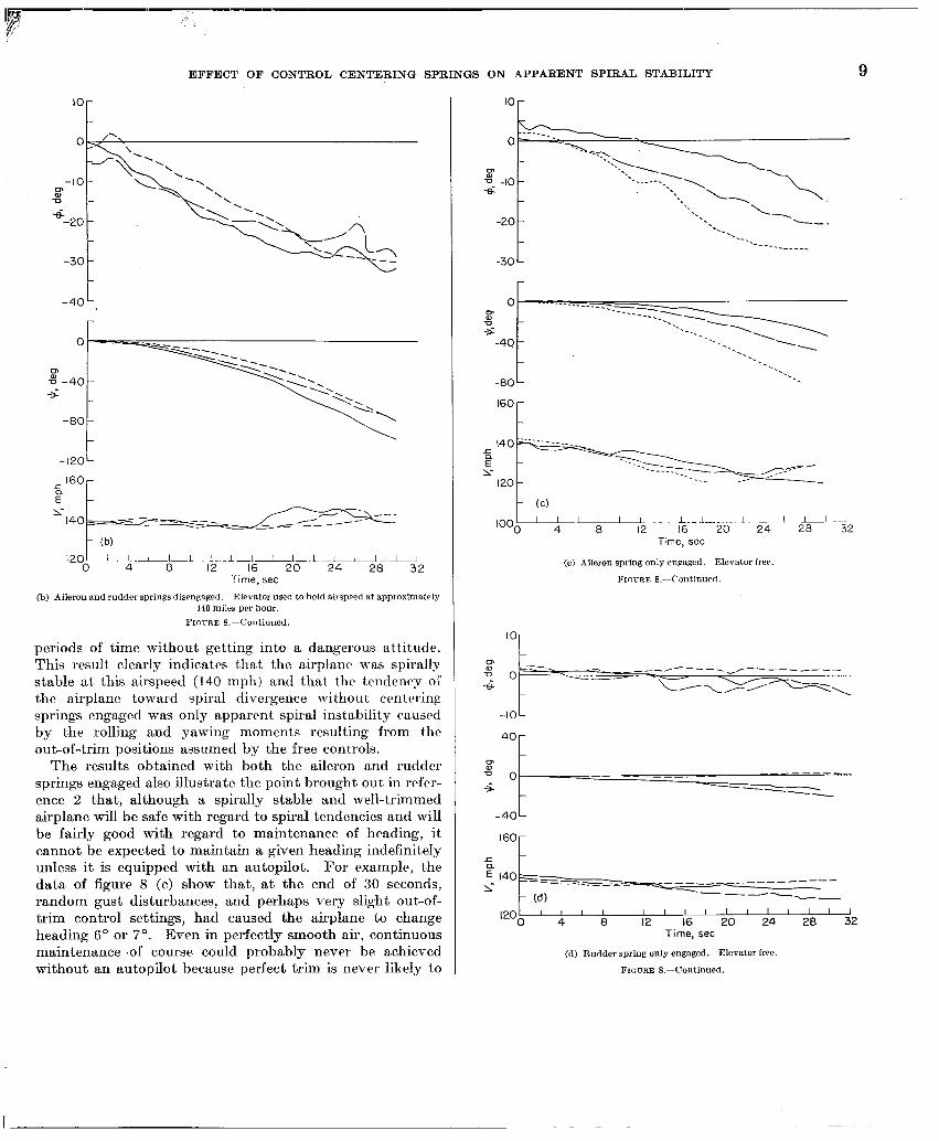
Effect of centering springs on lateral trim.-The data of figure 8 (a) for the airplane with the centering springs dis- engaged and the elevator free show that the uncontrolled motion was a spiral to the left and tha.t at the end of about 30 seconds a bank angle of about 20” or 30’ was reached. This apparent spiral instability was not reduced when the pilot controlled the elevator to keep the airspeed approxi- mately constant at 140 miles per hour. (See fig. 8 (b).) The data of figures 8 (c) and 8 (d) show that engaging only the aileron centering springs provided no substantial im- provement in the uncontrolled motions but that engaging only t.lie rudder centering springs almost entirely eliminated the spiral tendencies of the airplane. For this airplane, thcrc’fore, the most important out-of-trim moments with controls free were apparently produced by the rudder. With both the aileron and rudder springs engaged (fig. 8 (e)) the uncontrolled motion of the airplane was slightly better than that obtained with only the rudder springs engaged, at least with regard to the change in heading.
In these flights with both the rudder and aileron springs engaged the airplane would fly “hands off” for indefinite
EFFECT OF CONTROL CENTERING SPRINGS ON APPARENT SPIRAL STABILITY
-80 -
t (b)
‘200L’ - 1L’-L L- _l-lI.Lii-l-iJ
4 8 12 16 20 24 28 32 Time, set
(b) Aileron and rudder springs disengaged. Elevator used to hold airspeed at approximately 140 miles per hour.
FIO~ZE 8.-Continued.
periods of time without getting into a dangerous attitude. This result clearly indicates that the airplane was spirally stable at this airspeed (140 mph) and that the tendency ol the airplane toward spiral divergence without crntcrinp springs engaged was only apparent spiral inatabilit,y caused by the rolling and yawing moments resulting from the out-of-trim positions aasumecl by the free controls.
The results obtained with both the aileron and rudder springs engaged also illustrate the point brought out in rcfer- ence 2 that, although a spirally stable ancl well-trimmed airplane will be safe with regard to spiral tendencies and will be fairly good with regard to maintenance of heading, it cannot be expected to maintain a given heading inclefinitely unless it is equipped with an autopilot. For example, the data of figure 8 (e) show that, at the end of 30 seconds, random gust disturbances, and perhaps very slight out-of- trim control settings, had caused the airplane to change heading 6’ or 7’. Even in perfectly smooth air, continuous maintenance .of course could probably never be achieved without an autopilot because perfect trim is never likely to
IO r
160
F
lOOk III -1 L.-l-..!._ 1~ I ! I 0 4 8 12 16 20 24 28 32
Time, set
(c) Aileron spring only eng:agod. Elevator free.
FIGURE S.--Continued.
-lOL 40 r
z? = o- ------ s --B ---
-4oL
160 r
- (d) . . ,201 ’ ’ ’ ’ ’ ’ ’ ’ ’ ’ ’ ’ ’ ’ ’ ’
0 4 8 12 16 20 24 28 32 Time, set
(d) Rudder spring only engaged. Elevator free.
FIGURE O.-Continued.

10 REPORT 1092-NATIONAL ADVISORY COMMITTEE FOR AERONAUTICS
.c ~4O~--------- -- z -
- (4
100 ’ ’ ’ ’ ’ ’ ’ ’ ’ ’ I ’ ’ ’ I I
0 4 8 12 16 20 24 28 32 Time, set
(e) Aileron and rudder springs engaged. Elevator free. FIGURE S.-Concluded.
be obtained in practice. The deviations in heading caused by slight unavoidable out-of-trim moments can, of course, be reduced by increasing the true spiral stability of the airplane as pointed out in reference 2. The apparent spiral stability can also be improved by minimizing the lateral trim changes caused by changes in airspeed, power, and fuel loading. The effect of airspeed on lateral trim for the test airplane is dis- cussed in a subsequent section.
Effect of centering springs in overcoming friction-The data of figure 9 illustrate clearly the effect of the centering springs in eliminating the detrimental effects of friction on the uncontrolled motion of the airplane after a rudder kick and release. The curves of figure 9 (a) show that with the center- ing springs disengaged the rudder did not return to the original position after being deflected and released. This failure of the rudder to return to the original position is attributed mainly to the friction in the rudder control system, but, for one direction of rudder deflection, it could be partly caused by the tendency of the rudder to float at some angle other than that requirccl for trim. The yawing moments resulting from this out-of-trim rudder position caused the airplane to go into a spiral dive to the right after a right rudder kick and to the left after a left rudder kick. The in- creasing airspeed obtained in the spiral dive made it necessary for the pilot to terminate each test after a short time t.o prevent csccssive airspeeds from being reached.
2 i
c I3 -Right rudder kick --Left rudder kick
s
j:
-\ -20 ‘\
.----
t ‘\
\ -80 \
180 r \
I I I I I I I I I I I I I I 0 8 16 24 32 40 48 56
Time, set
(a) Aileron and rudder centering springs disengaged. FIGURE 9.-Motions following abrupt rudder kick and release. Elevator free. I’=145 miles
per hour (approx.) at start of maneuver.
The results presented in figure 9 (b) for the airplane with the centering springs engaged show that the rudder returned to the original position after being deflected and released and that the subsequent motions of the airplane were greatly different from those obtained with centering springs dis- engaged. The airplane recoverecl quickly from the relatively small angles of bank reached during the rudder kicks with the springs engaged and then appeared to be capable of main- taming an essentially wing-level attitude for an indefinite

EFFECT OF CONTROL CENTERING SPRINGS ON APPARENT SPIRAL STABILITY 11
2- i .P a
m
-Right rudder kick - -Left rudder kick
c - ? -_----- 1140 -- 0.9
o- 3; ’ 4’0 ’ 4i3 ’ 5’6 ’ $4 ’ i2 ’ do ’ Sk ’ 46 Time, set
(b) Aileron and rudder centering springs engaged. FIGURE O.-Concluded.
period. The airspeed varied only slightly during these tests and the changes in heading were relatively small compared with those which occurred when the centering springs were disengaged. The asymmetry of the curves for heading ($) in figure 9 (b) indicates that the airplane was not trimmed for straight flight but rather for a flat left turn when these records were obtained. TRUE SPIRAL STABILITY OF THE AIRPLANE WITH CONTROL CENTERING
SPRINGS ENGAGED
The results of the flight tests made to determine the true spiral stability of the airplane with the centering springs en- gaged and with the elevator used to hold the airspeed ap- proximately constant are presented in figures 10 and 11. The motions of the airplane during recoveries from various angles of bank up to 60” at an airspeed of 150 miles per hour are shown in figure 10. Similar records of recoveries from bank angles of loo or less at airspeeds of 120 and 90 miles per hour are presented in figure 11. The time required for the bank angle to decrease to one-half amplitude was determined from the average of the recoveries from both right and left bank angles.
The data of figure 10 indicate that the anplane had a moderate amount of spiral stability at 150 miles per hour since recoveries to an almost wing-level attitude from angles of bank as large as 60” were effected in approximately I min- ute. The average time required for the bank angle to de- crease to one-half amplitude appears from the records to be about 15 or 20 seconds.
The data of figure 11 show that as the airspeed was reduced the spiral stability decreased. The results of figure 11 (a) indicate that the airplane was still spirally stable at 120 miles per hour but that the time required for the angle of bank to decrease to one-half amplitude (25 or 30 set) was somewhat greater than that for 150 miles per hour. The pilot reported that the rapid recovery to a wing-level atti- tude near the end of the test that started with a 4O left bank was caused by a gust and was thus not. a true indication of the spiral stability of the airplane at this airspeed. The data of figure 11 (b) indicate that a definite reduction in spiral stability occurred when the airspeed was reduced to 90 miles per hour. These results do not show conclusively whethel the airplane was stable or unstable at this airspeed, but they
IP -~ --.--.

. . . . _--
REPORT 1092-NATIONAL ADVISORY COMMITTEE FOR AERONAUTICS
-- 160- ----
__--
--- -160 (b) --------- I I I I I I I I I I I I I I I-l-l-i-LI II
0 8 16 24 32 40 48 56 64 72 80 88 Time, set
(a) Initial bank angles less than 30’. (b) Initial bank angles greater than 30’. (Note change in vertical scale.)
FIGUBE lO.-Recovery from banked turns with aileron and rudder controls released. Aileron and rudder springs engaged. Elevator used to hold airspeed at approximately 150 miles per hour. Results of several flight records are shown.
do indicate that, since the degree of stability or instability was evidently slight, the airplane could be considered about neutrally stable.
A comparison of the measured and calculated spiral sta- bility of the airplane is presented in figure 12 in terms of the reciprocal of the time to damp to one-half amplitude for the spiral mode. The calculations were made by the method described in reference 3. The mass and aerodynamic param- eters used in the calculations are given in table II. The stability derivatives were estimated by the methods described in reference 3 and an approximate check of the derivatives Cns and C,, was obtained from flight test data on the airplane.
-20
80
I:
Time, set
D-8O - $
\ \
3 \ -120 - \
\
- (b) ‘1 -160 ’ ’ ’ ’ ’ ’ ’ ’ ’ ’ ’ ’ ’ ’ ’ ’
0 8 16 24 32 40 48’ 56 64 Time, set
(a) V=1!20 miles per hour (approx.). (b) V=90 miles per hour (appros.).
FIGURE Il.-Effect of airspeed on the recovery from banked turns with aileron and rudder controls released. Aileron and rudder springs engaged. Elevator used to hold airspeed approximately constant at values given. Results of several flight records are shown.
The data of figure 12 indicate that the measured spiral stability was somewhat greater than the calculated stability at all airspeeds and that the measured variation in stability with airspeed was greater than the calculated variation. The experimentally determined values are in qualitative agree- ment with the theoretical values in showing a reduction in spiral stability with decreasing airspeed. The failure to obtain better quantitative agreement can be attributed partly to possible inaccuracies in the estimation of some of the stability derivatives and partly to the lack of good quantita- tive experimental data, particularly at 120 and 90 miles per hour.

EFFECT OF CONTROL CENTERING SPRINGS ON APPARENT SPIRAL STABILITY 13
.08- - Experimental - -- Theoretic01
‘- ” /- ‘I
---- -
Tv2
t -.04[ I I I I I I , I
160 140 120 100 80 V, mph
FIGURE 12.-Comparison of experiments1 and theoretical velues of the reeiprocnl of the time to damp to one-half amplitude for the spiral mode.
TABLE II.-MASS AND AERODYNAMIC PARAMETERS USED IN SPIRAL-STABILITY CALCULATIONS
[The parameters y, CP,, and Cr, were assumed to he zero]
Parnmeter
C‘...------..---.-..........- 0.2G 0.40 0.71 .. a,deg 0.8 2. ti G. 5 ......................... n,deg .......................... -1.2 0. G rcxa 0.0% .......................... 0.0110 0.0110 I@ __ 0.0230 .......................... 0.0230 0.0230 Krz _ ......................... -0.OQO2 0. cm1 0. amI9 p* .......................... 5.80 5.80 5.80 c”8--...................-~ ..... 0.05 0.05 0.05 C,s-....................-...- .. -0.07 -0.07 -0.07 cyg.................-...~..- ... -0.28 -0.28 -0.28 C”, .................. ~._ ..-_ -0.042 .. -0.013 -0.023 CI,. .............. _. ... _. - _ _. -0.43 -0.43 -0.43 C”, ................... ._..-_ ._ -0.104 -0.102 -0.109 c+ .. ................... _ _ _ 0. 07 0. 09 O.lG
EFFECTS OF CHANGES IN AIRSPEED ON LATERAL TRIM AND APPARENT SPIRAL STABILITY
The motions of the airplane during recovery from banked turns with the centering springs engaged but with the eleva- tor free are shown in figure 13. Thcsc records were obtained under the same conditions as those of figure 10 except that the elevator was free in this case; whereas, the elevator was used to hold the airspeed constant in the t.ests recorded in figure 10. The results of figure 13 show that when the eleva- tor was free the airspeed varied greatly during the recoveries from the banked turns and the motions of the airplane were entirely different from those shown in figure 10. A compari- son of the results of figures 13 (a), 13 (b), and 13 (c) with those of figures 13 (d) and 13 (e) shows that the recoveries
-80 ” ” ” 1 ” ” ” ! ” ” ”
240 8 16 24 0 8 16 24 Time, set Time, set Time, set
(n) Initial bank angle (b) Initial bank angle (c) Initial bank angle approximately 30’ right. npproximntely 30” right. approximately 20° right.
I? I~UTRE l3.-Attempted recovery from banked turns with aileron and rudder controls re- leased. Aileron and rudder springs engaged. Elevator free. I’=150 miles per hour (approx.) at start of each record.
from right banked turns were greatly different from the recoveries from left banked turns when the elevator was free; whereas all the recoveries were quite similar when the airspeed was held constant. (See fig. 10.)
The results of figure 13 can be explained more clearly by first considering the results of figures 14 and 15, which show the effects of airspeed on lateral trim. The data of figure 14 show the aileron, rudder, and elevator deflections required to trim the airplane in level flight at various airspeeds. These data show that the change in aileron trim with airspeed was slight but that a sizable change in rudder trim was required with changes in airspeed. The c.hange in the required rudder trim was such that more left rudder was required with in- creasing airspeed. Or, expressed differently, the required trim change was such that increases in airspeed with the rudder held fixed would cause the airplane to be out of trim to the right. This effect is illustrated by the flight records presented in figure 15. All these records were obtained with the centering springs engaged and with the airplane trimmed laterally and directionally for an airspeed of 150 miles per hour. When the airspeed was held at 150 miles per hour, the> airplane maintained an essentially wing-level attitude; but when the elevator setting and power were varied to increase or decrease the airspeed, the airplane started a gentle spiral to the right or left. At an airspeed of 160 miles per hour a steady right turn at 20’ bank was reached and at 140 miles per hour a steady left turn at loo bank was reached. The data of figure 14 indicate that these turns were produced by out- of-trim rudder settings of less than O.l” in each direction.
-- , I , I . , . . , . m . , , , , , . . . -,-,-,,-,,-11-1.11.1 I.111 11.1, I_. . . ..---m..- m.--. - -.--. . m. . ,s-. . . . --_ . ..- ‘.-__ -..

14 REPORT 1092- NATIONAL ADVISORY COMMITTEE FOR AERONAUTICS
r -80
r 0 z i
-80
-480 t
al7 013 d Cd) 2
II,,,,, 1 I I I I II I I I I I I II I ! 0 20 40 60 80 100 120 140 160 180 200 220 240
Time, set
9 8 2 IF--/ , (e)
0 8 I6 Time, set
(d) Initial bank angle approximately 40’ left. (Note change in Scales.) Froum 13.-Concluded.
(e) Initial bank angle approximately 60’ left.
The critical nature of the lateral and directional trim problem is apparent from these results.
The data of figures 14 and 15 can now be used to explain the results presented in figure 13. The records presented in figures 13 (a), 13 (b), and 13 (c) for attempted recoveries from banked turns to the right with elevator free indicate that the airplane had little or no tendency to recover from the turn; that is, the bank angle remained approximately constant. In all these tests the pilot had to terminate the test after only a very short time to prevent excessive air- speeds from being reached. The failure to recover from these right turns is. attributed to the out-of-trim moments to the right caused by the increasing airspeed. These moments opposed and were apparently about equal to t,he restoring moments produced by the inherent spiral stabilit,y of the airplane.
The records presented in figures 13 (d) and 13 (e) for re- coveries from banked turns to the left with elevator free show that initially the airspeed increased and the airplane
mcovered rapidly toward a -wing-level attitude. In these cases the out-of-trim moments to the right caused by in- creased airspeed apparently reinforced the restoring moments to the right produced by spiral stability so that rapid.recov- eries were obtained. The recoveries were not considered satisfactory, however, because in one case (fig. 13 (d)) a virtually undamped longitudinal-lateral oscillation was ob- tained and in the other case (fig. 13 (e)) the pilot had to stop the recovery before 0’ bank was reached because the air- speed became excessive.
The flight record presented in figure 13 (d) is particularly interesting in that it shows the interaction of the longitudinal and lateral motions of the airplane. The period of the motion (appros. 55 set) appears to be about the same as that of the phugoid or long-period longitudinal oscillation which is usually a rather lightly damped motion. The fiuctuations in airspeed during the longitudinal oscillation apparently produced out-of-trim moments alternately to tlw right and left which caused the airplane to roll back and

EFFECT OF CONTROL CENTERING SPRINGS, ON APPARENT SPIRAL STABILITY 15
L: mph FKURE 14.-Variation with airspeed of the control-surface deflections required for trim
forth between about 0’ and 20’ left bank with the same 55-second period and to have similar periodic changes in heading. Since the oscillation in bank would, in turn, be expected to cause changes in airspeed (increased airspeed with increased bank angle) and since a certain amount of lag is inherent in these interactions between airspeed and bank angle, it does not appear surprising that the undamped longitudinal-lateral oscillation occurred.
All the records of figure 13 show that the free elevator generally tended to float to a lower setting with increasing airspeed, an indication that the stick-free longitudinal stability was less than the stick-fixed longitudinal stability. This change in elevator position with airspeed aggravated the tendency of the airplane to increase airspeed in the turn. No flights were made in which an attempt was made to hold the elevator fixed during recoveries from banked turns, but it is believed that such recoveries would be better than those obtained with elevator free. Therefore, it appears that control centering springs in the elevator system might provide some improvement in the apparent spiral stabilit*y. Even tiith the elevator fixed, however, the airspeed will vary during recoveries from banked turns so that the use of elevator centering springs should not be expected to lead to recoveries as good as those obtained with the airspeed held constant. If elevator centering springs are used, considera- tion should be given to possible detrimental effects of such springs on the elevator control-force characteristics.
Although all the flight tests were made in smooth or On the basis of- the results of this investigation, it appears moderately rough air, an indication of the apparent spiral that the changes in lateral and directional trim produced by
Approxtmote values of IS mph
80- --- 140
-\
\ I ,,,,I, I I II I I~IIII I I I I II
16 24 32 40Timz~se$6 64 72 80 88 96 #
FIGURE K-Effect on the lateral motions 01 increasing or decreasing the airspeed from thn airspeed at which the airplane is trimmed laterally and directionally (150 mph). Aileron and rudder springs engaged. Elevator used to hold airspeed approximately constant at values shown.
stability characteristics of the airplane in very rough air can probably be obtained from the data presented in figures 10 and 13. These results indicate that recovery from the large angles of bank that are likely to be produced by large gust disturbances will probably not be satisfactory unless the airspeed is held essentially constant by use of the elevator. Therefore, the previously mentioned results which indicated that the airplane with both centering springs engaged would fly “hands off” for indefinite periods of time without getting into a dangerous attitude might not apply to flights in very rough air.

16 REPORT 1092-NATIONAL ADVISORY COMMITTEE FOR AERONAUTICS
changes in airspeed, power, and fuel loading must be mirii- mized before completely satisfactory results can be expected from control centering springs. For the best results it appears, also, that the true spiral stability should be greater than that for the test airplane since very small out-of-trim deflections were shown to produce rather large angles of bank. The determination of what constitutes satisfactory apparent and true spiral stability was considered beyond the scope of this investigation, which was concerned primarily with whether control centering springs could make the appar&t s$%l stability as good as the true spiral stability. Some indication of the improvement in spiral stability that will result from various modifications to the airplane can be obtained from the methods and data presented in reference 2.
EFFECT OF CENTERING SPRINGS ON CONTROL FORCES
The nonlinear force variation provided by the positivc- action preloaded centering springs (fig. 1) caused a corrc- sponding nonlinear variation of control forces when the ccn- tering springs were engaged. This nonlinearity caused a noticeable “bump” in the control forces as the controls were moved through the neutral position and caused an increase in the breakout control force required to deflect the control from the centered position. (See fig. 4.) In the case of the ailerons, the static friction was fairly small (about l&lb wheel force) so that the spring preload used was not sufficient to make the “bump” or the increased breakout force (about S.&lb wheel force) objectionable to the pilots. In the case of the rudder, however, the static friction was large (about IO-lb pedal force) and the spring preload required. was correspondingly large so that the breakout force was about 22 pounds. Since this increase in rudder breakout force increased the diaculty of making smoothly coordinated turns with the airplane, the rudder control-force charactcr- istics were not considered entirely satisfactory by the pilots.
Since the breakout control force required to deflect the centrals from the centered position is a function of the static friction and the spring preload and since the spring preload required is in turn a function of the static friction, it is apparent that the static friction in the control system must be kept small to avoid objectionably large breakout control forces. Revision of the rudder control system of the test airplane to reduce the static friction was considered beyond the scope of the present investigation. It is felt, however, that if this friction were substantially reduced, the resulting reduction in spring preload required and, hence, in the breakout force would probably eliminate the objec- tions to the rudder control-force characteristics of the test airplane.
Use of the centering springs as a means for trimming the controls requires an additional amount of preload to provide
the forces necessary to hold the controls in the desired trim positions. If this additional preload required for trimming is large, the control forces are likely to be objectionably high. In addition, when the centering springs are used for trimming, the breakout forces become unsymmetrical; and if a large preload is required for trimming, this asymmetry is likely to be objectionable.
In the present tests, the preload in the rudder centering device was sufficient at cruising speeds to trim the airplane in wing-level flight . Although, as pointed out previously, the breakout forces were objectionably high, the asymmetry in the breakout forces was not considered objectionable. The rudder deflection, and hence the rudder force, required for trim increased with decreasing airspeed (fig. 14), however, so that the rudder preload was inadequate at the lower airspeeds. In order to trim at these lower airspeeds it was nctiessary to use aileron trim together with the maximum available rudder trim and to fly in a slightly banked attitude rather than with the wings level. Since the rudder preload required at cruising speeds resulted in excessive breakout forces, it is apparent that the increase in preload required for satisfactory rudder trim at the lower airspeeds would result in even more objectionable rudder breakout forces. This increase in the preload required for trim would prob- ably also make the asymmetry of the breakout forces objectionable.
Another factor which must be considered in designing for satisfactory control-force characteristics with preloaded centering springs is the variation of spring force with control deflection. In this connection, one important design param- eter is the ratio of the spring deflection required to produce the desired preload to the total spring deflection resulting from full control deflection. Small values of this ratio are likely to produce excessively large control forces. If the ratio is large, however, the increase in the control forces caused by the centering springs will probably not be objectionable provided, of course, that the preload is not very large. It appears therefore that the use of a spring that must be almost fully compressed to produce the desired preload will probably result in the most satisfactory control- force characteristics.
For some airplanes, particularly those that have large amounts of friction in the control system and hence require centering springs with large amounts of preload, some pro- vision might be desirable for disengaging the centering devices at take-off and landing and during extensive maneu- vering or acrobatics. The most satisfactory installations will probably be obtained, however, when the friction in the control system is reduced enough to permit the use of permanently engaged centering devices.
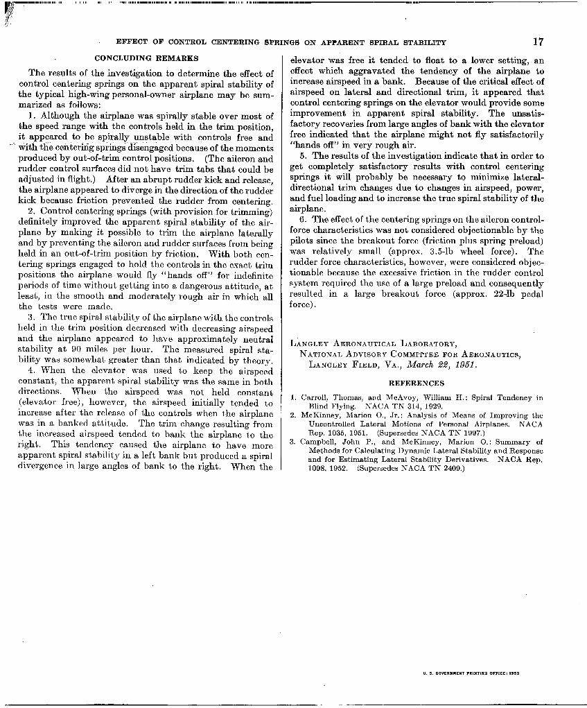
EFFECT OF CONTROL CENTERING SPRINGS ON APPARENT SPIRAL STABILITY 17 CONCLUDING REMARKS
The results of the investigation to’determine the effect of control centering springs on the apparent spiral stability of the typical high-wing personal-owner airplane may be sum- marized as follows:
1. Although the airplane was spirally stable over most of the speed range with the controls held in the trim position, it appeared to be spirally unstable with controks free and
’ tiith the centering springs’disengaged because of the moments produced by out-of-trim control positions. (The aileron and rudder control surfaces did not have trim tabs that could be adjusted in flight.) After an abrupt rudder kick and release, the airplane appeared to diverge in the direction of the rudder kick because friction prevented the rudder from centering.
2. Control centering springs (with provision for trimming) definitely improved the apparent spiral stability of the air- plane by making it possible to trim the airplane laterally and by preventing the aileron and rudder surfaces from b&g held in an out-of-trim position by friction. With both ccn- tering springs engaged to hold the controls in the exact trim positions the airplane would fly ‘Lhands off” for indefinite periods of time without getting into a dangerous attitude, at least, in the smooth and moderately rough air in which 0.11 the tests were made.
3. The true spiral stability of the airplane with the controls held in the trim position decreased with decreasing airspeed and the airplanc appeared to have approximately neutral stability at 90 miles per hour. The measured spiral sta- bility was somewhat greater than that indicated by theory.
4. When the elevator was used t,o keep the airspeed constant, the apparent spiral stability was the same in both directions. When the airspeed was not held constant (elevator free), however, the airspeed initially tended to increase after the release of the controls when the airplane was in a banked attitude. The trim change resulting from the increased airspeed tended to bank the airplane to the right. This tendency caused the airplane to have more apparent spiral stability in a left bank but produced a spiral divergence in large angles of bank to the right. When the
elevator was free it tended to float to a lower setting, an effect which aggravated the tendency of the airplane to increase airspeed in a bank. Because of the critical effect of airspeed on lateral and directional trim, it appeared that control centering springs on the elevator would provide some improvement in apparent spiral stability. The unsatis- factory recoveries from large angles of bank with the elevator free indicated that the airplane might not fly satisfactorily “hands off” in very rough air.
5. The results of the investigation indicate that in order to get completely satisfactory results with control centering springs it will probably be necessary to minimize lateral- directional trim changes due to changes in airspeed, power, and fuel loading and to increase the true spiral stability of the airplane.
6. The effect of the centering springs on the aileron control- force characteristics was not considered objectionable by the pilots since the breakout force (friction plus spring preload) was relatively small (approx. 3.5-lb wheel force). The rudder force characteristics, however, were considered objec- tionable because the excessive friction in the rudder control system required the use of a large preload and consequently resulted in a large breakout force (approx. 2%lb pedal force).
LANGLEY AERONAUTICAL LABORATORY, NATIONAL ADVISORY COMMITTEE FOR AERONAUTICS,
LANGLEY FIELD, VA., March %?, 195i.
REFERENCES
1. Carroll, Thomas, and McAvoy, William H.: Spiral Tendency in Blind Flying. NACA TN 314, 1929.
2. McKinney, Marion O., Jr.: Analysis of Means of Improving the Uncontrolled Lateral Motions of Personal Airplanes. NACA Rep. 1035, 1951. (Supersedes NACA TN 1997.)
3. Campbell, John P., and McKinncy, Marion 0.: Summary of Methods for Calculating Dynamic Lateral Stability and Response and for Estimating Lateral Stability Derivatives. NACA Rep. 1098, 1952. (Supersedes NACA TN 2409.)