I GIIIIIIlID I - NASA
194
i I I I I I I i I I ! I | /, .... : .... i / !, j., , J l l I TRZK203768CK [ FEASIBILITY STUDY AND DESIGN CONCEPT FOR THE COM/_UTER-CONTROLLED LAUNCH SET GD[C-BTD65-127 CONTRACT NAS3-3232 30 August 1965 Approved_. L. Newman Ass't. Chief Engineer Guidance and Control GIIIIIIlID IBmNmWmJl_l.. I_YNAMICm I CONVAII_ il,t_ b
Transcript of I GIIIIIIlID I - NASA

i
I
I
II
II
iI
I!I
| /,
.... : .... i / !,
j., ,
J
l
l
I
TRZK203768CK [
FEASIBILITY STUDY AND
DESIGN CONCEPT FOR THE
COM/_UTER-CONTROLLED
LAUNCH SET
GD[C-BTD65-127
CONTRACT NAS3-3232
30 August 1965
Approved_. L. Newman
Ass't. Chief Engineer
Guidance and Control
GIIIIIIlIDIBmNmWmJl_l.. I_YNAMICm I CONVAII_
il,t_
b

GD IC-BTD65-127
FOREWORD
This report was written in accordance with the requirements of Change Orders 361
and 589 to contract NAS3-3232.
One section of this report documents the results of a study performed to investigate
the feasibility of using a Scientific Data Systems (type 910 or 930) computer to auto-
matically checkout and calibrate the Centaur guidance system. During the study
certain functions were demonstrated on a guidance system using the autopilot ATE-2
test set (located in San Diego) which contains an SDS 910 computer. The results of
this work are included herein. This portion of the work was performed under Contract
NAS3-3232, Change Order 361. This document is the final report required by Change
Order 361 and completes the General Dynamics/Convair effort.
After the receipt of C.O. 361, but prior to the completion of the study, NASA
authorized (via Change Order 589) Convair to proceed with the task of designing a
Computer-Controlled La_unch Set (CCLS). As a result, this report also contains a
detailed design concept for the CCLS, and is more complete than the feasibility study
alone would have been. Sections on guidance/autopilot and autopilot checkout and
launch are included for completeness.
Coordination with NASA/LeRC and Honeywell was maintained throughout the study so
_ their feelings and requirements could be integrate_! in, n the conclusions and
recommendations as fully as possible.
o°°
111

GD 1C-BTD65-127
A design concept for the Computer-Controlled Launch Set (CCLS) is described herein.
The CCLS consists of an ATE-2230 Automatic Test Set, a DD-10 Display System,
and auxiliary electronics used to directly interface the ATE-2230 with the guidance
system.
The heart of the ATE-2230 is an SDS 930 computer - a high speed, low cost, general
puu_pose digital computer confignred _dth 12,288 words of core storage. A priority
interrupt system which is capable of suspending execution of the in-process program
when guidance system or ex_ernal timing signals demand immediate processing is
provided, tn addition, standard input/output devices, including a magnetic tape unit,
a disc file storage unit, a teletypewriter, a card reader, and a paper tape reader and
punch are provided. In addition, the ATE-2230 includes digital-to-analog and analog-
to-digital converters to allow the computer to process and control analog signals, as
well as digital logic circuitry to allow both single- and 24-bit information to be
processed into or out of the computer.
The display system outputs alphanumeric status and control information on the face of
a cathode ray tube. This information allows the operator to be completely informed of
system test status, and provides him with the capability of manually executing control
of the test, when he so desires, by entering commands via the display keyboard.
The auxiliary electronics will:
a. Signal condition the analog and digital simms o_ginat_,g in the guidance system
so they will be acceptable to the computer input circuitry.
b. Contain the digital buffer circuits that store digital information until the computer
is ready to accept it.
c. Provide the power and control circuitry so that the gu_ance system can be turned
on and sequenced through the checkout and launch operations.
The concept of CCLS testing is to checkout and launch the guidance system employing
a philosophy similar to the one being used at present, in that the tests which will be
conducted, and the manner in which they will be conducted will not be changed. A
ground computer rather than the airborne computer will control the tests, thereby
providing automatic data reduction, considerably increased monitoring, and more
flexible control capabilities.
The test concept and portions of the design concept were demonstrated using the auto-
pilot checkout SDS 910 computer in San Diego. Communication with the airborne
computer and platform gimbal coarse alignment control were given special emphasis.
V

Section
3
GD]C-BTD65-127
TABLE OF CONTEN_rs
INTRODUCTION ............
I.I
1.2
1.2.1
1.2.2
1.2.3
1.3
Types of Computer-Controlled Checkout ....
Ground Computer Requirements .......
General Requirements of the Centaur Program . .
Functional Requirements .........
Computer-Controlled Launch Set ......
Study Work Plan and Final Report Structure . .
TECHNqQUE OF COMPL_ER-CONTROLLED CHECKOUT
2.1
2.1.1
2.1.2
2.2
2.2.1
2.2.2
2.2.3
2.2.4
2.2.5
2.2.6
2.2.7
2.2.8
2.3
2.4
2.4.1
2.4.2
2.5
2.5.1
2.5.2
The Logic of Man-Machine Decision .....
The Control ProgTam ...........
Displays ...........
Computer-Controlled Guidance Checkout ....
Routine Data Logging Technique ........
Electrical Interface ...........
Guidance System Power Control ........
System Functional Testing .........
Airborne Computer Operations .......
Coarse Alignment ...........
Optical Azimuth Alignment ........
C alibration .............
Computer-Controlled Autopilot Checkout ....
Computer-Controlled Guidanee/Autopilot Checkout . .
Integrated Test ............
FACT Test, Tanking Test, and Composite Readiness
Test ................
Computer-Controlled Guidance Launch Countdown . .
Guidance Launch Ladder Using the CCLS .....
Guidance Redline and Parameter Philosophy Using the
CCLS ...............
MANAGEMENT PLAN
3.1
3.1.1
3.1.2
3.2
Organization and Description of the Engineering Task .
Hardware Section ............
Software Section ...........
Control, Release, and Documentation of CCLS Computer
Programs .............
vii
Page
1-1
1-3
1-4
1-4
1-5
1-8
1-11
2-1
2-1
2-2
2-3
2-4
2-4
2-5
2-6
2-6
2-7
2-22
2-24
2-26
2-26
2-27
2-28
2-28
2-28
2-29
2-30
3-1
3-1
3-1
3-3
3-4

Section
GD[C-BTD65-127
TABLE OF CONTENTS, Contd
3.3
3.4
Control and Release of the CCLS Configuration . .
Compatability of the Hardware and Software, Preflight
and Inflight, Airborne and Ground Equipment . . .
3.5 ETR Procedures ............
3.6 Continuous Parts Support and Maintenance . . .
3.7 Failure Analysis ............
3.8 Program Implementation Schedule .......
IMPLEMENTATION OF COMPUTER-CONTROLLED CHECKOUT
4.1
4.1.1
4.1.2
4.1.3
4.2
4.2.1
4.2.2
4.3
4.3.1
4.3.2
4.3.3
4.3.4
4.3.5
4.3.6
4..3.7
4.4
4.4.1
4.4.2
4.4.3
4.5
4.5.1
4.5.2
4.5.3
4.5.4
4.6
4.7
4.7.1
4.7.2
The Executive Control Technique ......
Example of Executive Control ........
Out-of-Tolerance Data Handling .......
Format of the Display ..........
Programming Languages .........
Assembly and Compiling .........
Development of Operational ATE-2230 Programs . .
The ATE-2230 ............
Priority Interrupt System .........
Single Bit Input and Output ..........
Parallel (24 Bit} Input or Output .......
Data Multiplex System ..........
Display System ............
Digital-to-Analog Converters ........
Time-Multiplexed Communication Channels ....
CCLS Validation ............
SDS Computer and Standard Input/Output Unit
Validation ..............
System Input/Output Validation .......
Guidance Umbilical Line Validation ......
Electrical Interface ...........
Analog Voltage Measurements ........
AC Signal Measurement ..........
Digital Signal Processing .........
MGS Relay Control ...........
Installation of the CCLS at ETR .......
System Calibration ...........
MUSRA by Azimuth Alignment Technique .....
MUSRA by 45-Degree Offset Drift Off-Level ....
viii
Page
3-6
3-7
3-7
3-7
3-8
3-8
4-1
4-1
4-2
4-3
4-5
4-5
4-8
4-13
4-13
4-13
4-14
4-15
4-15
4-18
4-21
4-21
4-24
4-25
4-25
4-29
4-29
4-40
4-64
4-71
4-86
4-90
4-94
4-95
4-98

GDIC-BTD65-127
Section
6
Appendix
A
B
TABLE OF CONTENTS, Contd
Accelerometer Input Axis Misalignment by 45-Degree
Offset from Level ...........
Summary of Calibration Without Optics .....
THE FEASIBILITY DEMONSTRATION ......
5.1
5.2
5.2.1
5.2.2
5.3
5.4
5.4.1
5.4.2
5.4.3
5.4.4
5.5.1
5.5.2
5.5.3
Feasibility Study Ground Rules .......
Power Control ............
Computer Power Control ..........
Airborne Computer Reinitialization ......
Computer Functional Test ........
Ground to Naxqga_ion Computer Communication . . .
Loading SDS Memory _dth Data for Communication . .
Data Communication to the Airborne Computer o . .
Data Readout from the Airborne Computer .....
Display of Data ............
Gimbal Coarse .A2ign__ment..........
Problem Definition ..........
Gimbal Torquing Software .........
Gimbal Torquing Hardware .........
REFERENCES .
BEST COMMERCIAL PRACTICE DRAWINGS ......
PRECISION" DC SIGNAL MONITORING CIRCUIT DESIGN
ix
Page
4-99
4-100
5-1
5-1
5-2
5-3
5-3
5-5
5-7
5-8
5-9
5-9
5-9
5-9
5-10
5-11
5-14
6-1

Figure
1-1
2-1
2-2
2-3
2-4
2-5
2-6
2-7
3-1
3-2
3-3
4-1
4-2
4-3
4-4
4-5
4-6
4-7
4-10
4-11
4-12
GDIC-BTD65-127
LIST OF ILLUSTRATIONS
Computer-Controlled Launch Set ..........
Mode Selection Routine in Airborne Computer ......
Airborne Computer Communication Program Flow Diagram . .
Temporary Storage Calibration Program Functional Flow . . .
Temporary Storage Final Align Program Functional Flow . . .
Airborne Computer Functional Testing Flow Diagram . . .
CCLS Gimbai __tignrnent Control Diagram ........
Manual GSE Optical Alignment Equipment Location .....
Electronic Circuit Design Flow Chart .........
Software Section Operation Flow Chart ........
Preliminary CCLS Schedale ...........
Data Display -- Preliminary Sectionalization of the Display Face .
Second Path to Memory Display and Analog Data Handling . . .
General Configuration for Analog Signal Measurement ....
Multiplexer Input Configuration .........
Grounding for Analog Signal Monitoring ........
Monitoring Circuitry for a Typical TCA Output ......
Monitoring Circuitry for Accelerometer Modulator Coil
Excitation .................
+35 VDC Monitoring Circuit ............
Monitoring Circuitry for Gimbals 1, 2, 3, and 4 Servo Motor
Signals ..................
Monitoring Circuitry for Gyro Torque Signal .......
Monitoring Circuitry for Gimbal No. 4 Caging Relay Signal
Conditioner Signal ..............
Monitoring Circuitry for Phase-Sensitive Power Demodulator
Signal Conditioner Signal ............
Page
1-9
2-9
2-11
2-13
2-14
2-17
2-23
2-25
3-2
3-5
3-9
4-6
4-16
4-41
4-42
4-43
4-46
4-49
4-51
4-52
4-54
4-55
4-56
xi

GD[C-BTD65-127
Figure
4-13
4-14
4-15
4-16
4-17
4-18
4-19
4-20
4-21
4-22
4-23
4-24
4-25
4-26
4-27
4-28
4-29
4-30
4-31
4-32
4-33
4-34
4-35
4-36
LIST OF ILLUSTRATIONS, Contd
Monitoring Circuitry for U, V, W Gyro Torque Signal
Conditioner Signals ..............
Monitoring Circuitry for Signal Conditioner U, V, W Steering
Signals .................
Monitoring Circuitry for Signal Conditioner X, Y Steering
Signals ..................
Monitoring Circuitry for Signal Conditioner Gimbal 1, 2, 3, 4
Demodulator Outputs ............
Guidance System Prime-Power-Fail Detector Circuit . . •
Input Waveform to Schmitt Trigger ........
Power-Fail-Circuit Timing Diagram ........
Computer Input/Output Block Diagram .......
Delta-V Counter Synchronization Logic and Timing ....
Delta-V Counter Logic Block Diagram .......
Missing-Bit Monitoring Logic ..........
Excess-Bit Monitoring Logic ..........
Excess Limit Cycle Monitoring Logic ........
Input/Output of Mode Line Buffer .........
Parallel Mode-Line Output Buffer Logic • • .....
Countdown Time Decoder Input/Output Block Diagram . . .
Single Decade Decoder Logic ..........
Countdown-Time Decoder Block Diagram ......
Telemetry Buffer Input/Output Block Diagram .....
Launch-On-Time Decoder Input/Output Diagram ....
Launch-On-Time Decoder Logic Block Diagram ....
CCLS Relay Configurations ...........
Proposed CCLS Installation in Complex 36 Basement . • .
CCLS Interface ..............
xii
Page
4-58
4-60
4-61
• 4-63
• 4-67
• 4-68
• 4-70
• 4-72
• 4-73
• 4-74
• 4-75
• 4-76
• 4-77
• 4-78
• 4-79
• 4-80
• 4-82
• 4-83
• 4-84
• 4-85
• 4-87
• 4-88
• 4-91
• 4-93

I
!!
I
II
lIiI
I
I
I
III
!Il
Figure
4-37
4-38
4-39
5-1
5-2
5-3
5-4
5-5
5-6
5-7
B-1
B-2
B-3
GDIC-BTD65-127
LL_T OF ILLUSTRATIONS, Contd
Platform Orientation for MUSRA Evaluation Using Azimuth
Alignment Technique .............
Platform Orientations for MUSRA Evaluation Using 45-Degree
Offset, Drift Off-Level Technique ........
Platform Orientation for Accelerometer Input Axis Misalign-
merit Evaluation .............
Airborne Computer Power Turn-On .........
Airborne Computer Functional Testing ........
Manual GSE Coarse Aligrm_ent Loop Configuration ....
ATE-2 GimbaI Alignment Control Diagram ......
Coarse a_d Fine Align Mode Control Program Block Diagram .
Gimbal Alignment Control Program Block Diagram ....
Gimbal Torquing Output, T}-pical Channel .......
DC Signal Monitoring Circuit Configuration ......
Simplified DC Signal Monitoring Circuit .....
Simplified DC Signal Monitoring Circuit (For Capacitor Value
Derivation) ................
Page
4-95
4-98
4-99
5-4
5-6
5-10
5-12
5-13
5-15
5-16
B-1
B-2
B-5
I xiii

GDIC-BTD65-127
LIST OF TABLES
Table
2-1
4-1
4-2
4-3
4-4
4-5
4-6
4-7
4-8
4-9
4-10
4-11
4-12
4-13
4-14
4-15
4-16
4-17
4-18
4-19
Gimbal Loop Gains and Damping .........
Program Status Information Typical Display ......
Programming Language Development Status .....
A Symbol Source and Object Program ........
Display Selection Summary . .........
CCLS Interface Summary ............
Parameter Values for Torquing Potentiometer Excitation
Measurement ..............
Parameter Values for Gyro Pattern Field Supply
Measurement ...............
Parameter Values for Gy _n _n_ _cce!erometer Temperature
Control Amplifier Measurements .........
Parameter Values for TCA Heater Supply Measurement . .
Parameter Values for Accelerometer Modulator Coil
Excitation Measurement ..........
Parameter Values for +28VDC Supply Measurement . . .
Parameter Values for +35VDC Supply Measurement . . .
Parameter Values for Gimbals 1, 2, 3, and 4 Servo Motor
Measurements ..............
Parameter Values for Gyro Torque Signal Measurement .
Parameter Values for Gimbal 4 Cage Signal Conditioner
Signal Measurement ............
Parameter Values for Phase-Sensitive Power Demodulator
Measurements .............
Parameter Values for U, V, W Gyro Torque Signal Conditioner
Signal Measurements
Parameter Values for Steering Input Measurements . • •
Parameter Values for Signal Conditioner X, Y Steering Signal
Measurements ..............
XV
Page
2-23
4-7
4-8
4-10
4-20
4-30
4-45
4-46
4-47
4-48
4-49
4-50
4-51
4-53
4-54
4-56
4-57
4-58
4-60
4-62

GDIC-BTD65-127
Table
4-20
4-21
4-22
4-23
5-1
5-2
LIST OF TABLES, Contd
Parameter Values for Signal Conditioner Demodulator Output
Measurements .......
Countdown Time Decoder Input Data ........
BCD Countdown Register Output Data ........
Latching Relay Truth Table ...........
SDS Data Input Format ............
Communication Display Format ..........
Pag......._e
4-63
4-80
4-81
4-88
5-8
5-9
xvi

i
i
lII
II
I,I
II
III
II
I!
A_
ABM
AC
A/D
AMP
ATE
ATOLL
AVE
BCP
CCCB
CCLS
CIC
C.O.
c/o
CPS
CRT
CW
C K
_K
DC
DDI
DE L
DMC
DRM
DSC
DSIF
DVM
GD 1C-BTD65-127
DEFIAqTION OF SYMBOLS
Airborne
Advanced Bill of Materials
Alternating Current
Atlas-Centaur
Analog-to-Digital
Ampere
Amplifier
Automatic Test Equipment
Acceptance, Test, or Launch Language
Average
Best Commercial Practice
Centaur Change Control Board
Computer-Controlled Launch Set
Change Identification Control Number
Change Order
Checkout
Cycles Per Second
Cathode-Ray Tube
Clockwise
Clock Time or Clock Pulse
Nonclock Time
Direct Current
Data Display, Inc. (Division of Control Data, Inc. )
Deliver
Data Multiplex Channel
Drawing Room Manual
Data Subchannel
Deep Space Information Facility
Digital Voltmeter
xvii

D 1. • .D 3, d 4...d19
EAC
EID
ENA
EOM
ET
ETR
FACT
FORTRAN
GD IC
GERB
GOAS
GMT
GSE
g
G1, G2,...G4
HLT
H202
INFO
i/o
J
J41
JPL
KCPS
LeRC
LLIM
GD IC-BTD65-127
DEFINITION OF SYMBOLS, Contd
Inertial Component Calibration Coefficients
Error Analysis Committee
End Item Description
Coordinate System East-North-Azimuth
Energize Output Module
Elapsed Time
Eastern Test Range
Flight Acceptance Composite Test
Formula Translation, an Automatic Programming System
Convair Division of General Dynamics
Guidance Equation Review Board
Guidance Optical Alignment Shelter
Greenwich Mean Time
Ground Support Equipment
Local Gravity
Airborne Guidance Computer Discretes
Halt
Hydrogen Peroxide
Information
Input/Output
Launch-Day Dependent Constant
J-Constant Relating Launch-Window Start Time to LOT Time
Job Parts List
Kilocycles Per Second
Lewis Research Center
Lower In-Tolerance Limit
ooo
XVlll
il
I
III
II
II
I
II
l
III

!
I
ilIII
If
II
!i
l
!
!!
!U
i
IIIIIi
LOCP
LOT
L1, L2, . . . L16
MAM
MAR
MECO
MESA
MFD
MGS
MONO
MPS
MICROSEC
MSFC
MUIA
MUSRA
MUX
Mn
M0. •. M4, _/I1. • ._I4
NASA
N°C.
N.O.
ORD
OSP
OTC
PERT
PIN
PIP
GD IC-BTD65-127
DEFLNITION OF SYMBOLS, Contd
Local Optical Control Panel
Launch On Time
Airborne Guidance Computer Discretes
Multiple Access to Memory
Memory-Address Register
Main Engine Cutoff
Mesa Scientific Corporation
Manufactured
Missile Oaidanee System
Monostable Multixdbrator
Manufacturing Process Specification
Microsecond
Marshall Space Flight Center
Input Axis Mass-Unbalance
Spin Reference Axis Mass-Unbalance
Multiplexer
Airborne Guidance Computer Serial Scan Flip-Flop
Mode Control Lines
National Aeronautics and Space Administration
Normally Closed
Normally Open
Order
Outside Source Procurement
Out-of-Tolerance Condition
Program Evaluation Review Technique
Parallel Input
Product Improvement Plan
xix

PC)
POR
POT
PPS
PWR
PZE
QTY
RC
RCA
REF
RL&R
ROCP
RS
RT
_T
RTi
SCATE
SC
SCD
SCR
SDS
SIG
SKS
SMRD
SPEC
S_
s_
GD IC-BTD65-127
DEFINITION OF SYMBOLS, Contd
Purchase Order
Purchase Order Recquisition
Parallel Output
Pulse Per Second
Power
Programmed Zero
Quantity
Resistance-Capacitance Network
Radio Corporation of America
Reference
Remote Load and Read
Remote Optical Control Panel
Reset-Set
Logic Timing Signal
Logic Timing Signal
Logic Timing Signal
Self-Calibration, Alignment, and Testing
Stromberg-Carlson
Specification Control Drawing
Single Character Register
Scientific Data Systems, Inc.
Signal
Skip if Signal Not Set
Spin Motor Rotation Detector
Specification
Sector Alpha
Sector Beta
I
-.|
I
I
I
1
I
!i
I
I
I
I
I
I
I
I
I
I

I
T
TB
TCA
T/M
TMCC
Tff
T_
UAR
ULIM
U, V,W
V
VAC
VDC
Vcyu, Vcrv, Vcyw
WAR
WCR
A
k
P
¢
36A, 36B
GD[C-BTD65-127
DEFINITION OF SYMBOLS, Contd
Time
Terminal Board
Temperature Control Amplifier
Telemetry
Time-Multiplexed Communication Channel
Track Alpha
Track Beta
Real-Time-Accumulation Sigmator Cell
Unit-Address Register
Upper In-Tolerance Limit
Mutually Orthogonal Axes of an Inertial Coordinate System
Velocity
Volts, Alternating Current
Volts, Direct Current
Velocity Accumulation Sigmator Cells
Word-Assembly Register
Word-Count Register
Resolver Output
Rate of Resolver Output
Azimuth Alignment Angle
Incremental Change
Local Geodetic Latitude
Accelerometer Input Axis Misalignment Angle
Displacement Angle
Earth Rotation Rate
Ohm
Gyro Torquing Rate
Pads A and B, respectively, of Launch Complex 36
xxi

II
II
I
IIIi
IIII
I
II
III
GDIC-BTD65-127
SECTION 1
_TRODUCTION
On 19 February 1965, Change Order 361 was sent to General Dynamics/Convair by the
National Aeronautics and Space Administration, Lewis Research Center. This change
order directed GD/C to "conduct a study to investigate and evaluate the use of the
existing Scientific Data Systems Computer (presently used for autopilot checkout) for
automatically checking out and calibrating the Centaur Guidance System." It was
decided that the study would consist of two phases: 1) definition of a design concept to
be employed for a guidance checkout computer, and 2) a feasibility demonstration on
the autopitot checkout computer test set (ATE-2) to verify interface compatibility.
Change Order 361 was an outgrowth of discussions held over the previous months
between NASA and GD/C, culminating with the AC-5 design review held at GD/C in
January. of 1965. The discussion at the review established the need for a device that
would make additional permanent storage locations available to the inflight airborne
guidance computer program, since (at that time) there was only one unused permanent
storage word location in the AC-5 computer program.
The airborne guidance computer contains 2816 word locations available for program-
ming in its permanent storage section. Of these, the combined AC-5 preflight and
inflight programs allocated 1176 cells for preflight and 1639 cells for inflight use.
Utilization of a ground computer to perform the preflight functions would free a large
percentage of the 1176 locations for use by the inflight program. The availability of
additional locations for use by the inflight equations offers several advantages (besides
the obvious one of assuring adequate storage space for the inflight equations): ease of
programming, self-check features, and the possibility of reducing Centaur weight.
_nen a program is written for a computer that uses a drum for storage (as is the
case with the airborne computer), compute cycle time must often be wasted since the
computer cannot randomly input to particular storage locations, but must instead wait
until the drum turns to an unused location. As more locations become available for
use, i.e., when there are more free locations, the task becomes correspondingly
simpler since the programmer can space his program in a more optimum manner.
These additional spare storage locations could allow hardware improvements to be
made: 1) delete the inflight torquing of the platform gyros (Reference 1), 2) delete
the autopilot timers (use a computer-controlled sequencer) (Reference 2), and 3)
simplify the Atlas autopilot (Reference 2). The gyro torquing function could be replaced
by mathematically compensating the inflight equations for gyro drift. The timing
function of the Centaur autopilot timers could be accomplished by the Centaur guidance
1-1

GDIC-BTD65-127
computer. Booster steering, presently done by the Atlas autopilot, could be accom-
plished by the guidance system and neither the autopilot displacement gyros nor timer
would be required. These three simplifications alone could significantly increase
Centaur flight success probability.
The additional storage could also allow the airborne guidance program to be more
reliable. Reasonableness criteria could now be applied to input data and critical cal-
culation results. Then if a momentary failure occurs in the computer, the guidance
data and equations have a better chance of recovering without affecting the mission.
There are several factors, other than increasing the availability of airborne computer
storage locations, which make a ground computer desirable for checkout and launch.
Two major factors are: 1) a computer will perform the checkout function more thor-
ougbly than the present equipment, and 2) the chance for operator error can be
drastically reduced. The present guidance GSE uses a recorder, a voltmeter, a
counter, and some special circuitry for monitoring system performance. Continuous
monitoring is possible only for selected inputs, and only within the capability of the
above equipment and operator. All of the data taken must be analyzed by a human
operator with the attendant chance for error. Since a ground computer would monitor
a large number of inputs continuously without operator analysis, it would be possible
to do a more thorough job than is presently accomplished.
A ground computer is more flexible than manually-operated, relay-mechanized GSE.
When there are event sequencing changes, programming changes alone are required.
For example, a change was recently made to the present guidance GSE because the
discrete used to indicate flight mode acceptance by the airborne system was changed
to a different discrete. This change would not have affected any hardware if a ground
computer were being used; a program change alone would have resulted. To keep the
system flexible, the electrical interface between the ground computer and the guidance
system will be via a patchboard. This will allow changes to be accomplished in a
simple manner, since the patchboard can be used to connect the new (or different type)
signals to the appropriate input device (sense switch or analog-to-digital converter).
This type of flexibility has the advantage of allowing quick reaction to changes since
only a program and documentation change must be processed through the change
control cycle.
In addition to the advantages of flexibility and capability mentioned above, a properly
designed ground computer checkout system should be more reliable than a manual GSE.
This is because the design problems, which are usually solved in the field for special
purpose GSE, will already have been found in the computer, which is standard and is
in production. Also, the overall design concept may actually be simpler (digital
circuitry vs. analog). Further, although many circuit boards are used in the computer,
only a few basic circuits are actually employed.
1-2

GDtC-BTD65-127
i
I
I
I
I
I
I
i
I
I
i
I
t
,t
l
I
I
I. 1 TYPES OF COMPUTER-CONTROLLED CHECKOL_r. Once a decision has been
reached to use a computer for ground checkout, the method of implementation must be
chosen. Two basic methods are possible: I) the ground computer can control a set of
GSE, which in turn controls the airborne hardware, or 2) the ground computer can
control the airborne hardware, interfacing directly with the airborne system. Although
the first method has some historical appeal, it was found that the second method would
be more flexible and reliable, primarily because the interface between the computer
system and the airborne hardware would be far less complex. Whenthe interface is
directly with the airborne system, most of the special purpose circuitry and special
purpose design that exists in manually-controlled GSE can be deleted (the only excep-
tion usually being high frequency response systems}. This special purpose circuitry is
the portion of the manual GSE which is most unreliable, since it is a one-of-a-kind
design that has its ovv-n special problems, wbAch are generally not found until experi-
ence is accumulated on the equipment. This contrasts with general purpose computer
circuitry, which is produced for all the customers of the computer manufacturer. The
fact that the computer system is a collection of off-the-shelf production equipment
means that most of the design problems will have been solved before the computer getsto the launch site.
Another advantage of interfacing directly with the airborne system is that changes to
concept or interface are far more easily mechanized. For example, consideration is
now being given to torquing the g3_os to coarse a!ig_a the Centaur guidance platform
(at present coarse alignment is accomplished by torquing the gimbals themselves).
By interfacing directly with the airborne system, the change to gyro torquing for
coarse alignment can be easily made since the mechanization of either technique using
the Computer-Controlled Launch Set (CCLS) would use a digital-to-analog converter.
Patchboard changes, gain changes, and interconnections would be the only hardware
changes required to mechanize gyro torquing for coarse alignment.
Another example of an advantage of interfacing directly with the airborne system is
the easing of the problem of monitoring analog voltages and of making changes to limits
or signal characteristics. With the computer interfacing the airborne hardware directly,
one analog-to-digital converter (with suitable multiplexing) can monitor every analog
voltage in the system, thereby replacing all the recorders, demodulators, and volt-
meters performing the same function.
On the other hand, one advantage of having the computer control a set of GSE which,
in turn controls the airborne equipment is that the operator can control the system
without operating the computer. However, it was felt that this did not offset the ad-
vantages gained by having a simple interface. It is recommended that the design contain
this type of manual control only as an emergency provision. The following ground rule
will apply: regardless of the method by which the computer controls the airborne
equipment, the hardware shall allow the operator to turn off the airborne equipment if
the ground computer fails for any reason.
1-3

GDIC-BTD65-127
For these reasons it was decided to plan the system with the CCLS interfacing directly
with the airborne hardware with a minimum of special purpose equipment. Having
made this decision it is possible to delineate some of the basic requirements for the
system.
1.2 GROUND COMPUTER REQUIREMENTS. The ground computer basic require-
ments can be divided into two different types: those which are general in nature and
come about due to Centaur Program objectives (such as reliability), and those which
result from a specific hardware functional interface. The general requirements will
be considered first, then the detailed airborne interface will be reviewed; finally, a
machine configuration will be described which best satisfies the stated requirements.
1.2.1 General Requirements of the Centaur Program. The Centaur Program places
the following general requirements on the CCLS:
a. The total system should be designed with reliability in mind from the start. A
proven, off-the-shelf computer having field usage history should be chosen. The
computer must have been designed using acceptable components (silicon transistors
for example), and the circuit design must have been accomplished using reliable
design practices.
Do The system should use time sharing of hardware if it simplifies the configuration.
For example, a multiplexer which allows the majority of the analog input data to
be sampled by a single analog-to-digital converter is desirable.
c. The system design concept employed should be based on fail-safe concepts;
airborne equipment damage should not occur as a result of single ground
equipment failures.
d. The interface between the computer and the airborne equipment should be kept as
simple as possible so that proven, off-the-shelf subsystems are used insofar as
possible - the use of special purpose circuitry should be minimized.
e. Any circuitry designed especially for the launch set interface should be designed
using worst-case techniques and should use high reliability components.
f. The computer system must be capable of checking out the guidance system so that
all functions of the system will be exercised prior to flight.
g. It is desirable to have the computer programs (or portions thereof) used on the
CCLS compatible with the existing Scientific Data Systems (SDS) 910 computer
installed in San Diego, so that the ETR computer programs can be checked out
first in San Diego.
h. The CCLS must continually provide the operator with an indication of the airborne
system status.
1-4

GDIC-BTD65-127
1
I
I
I
I
I
I
II
I
I
I
i. The computer and program must be adaptive {capable of allowing the operator to
select the course of action he wishes to pursue). The operator must have displayed
at all times the program options he is allowed to perform.
jo A permanent, complete, and detailed historical record should be provided so that
postflight (or postcheckout) eval,lation may be carried out with complete knowledge
of the airborne system's characteristics and sequence of testing.
k. The control scheme must monitor the airborne system and react automatically
if imminent damage is sensed.
1. The various subprograms must have priorities assigned so that no equipment is
damaged by operator error, no data is lost, and the machine only undertakes
those programs that can be accomplished.
m. The CCLS must be capable of surviving a momentary ground power failure so that
the airborne system can be switched to a manual control mode before the CCLS
becomes nonoperative.
1.2.2 Functional Requirements. The specific functional requirements of the com-
puter will be derived by revie_qng the functional capability of the present GSE. As a
ground rule, the computer system should contain at least an equivalent functional
capability.
1.2.2.1 Functional Capability of the Present GSE.
Analog Inputs. The present GSE can process analog inputs in two ways: using an
AC/DC digital voltmeter or a Sanborn recorder. The digital voltmeter input can be
switched to monitor any one of the system voltages. If the voltage being monitored is
an AC voltage, a switch on the voltmeter is set to the AC position whereas if it is a DC
voltage, the switch is set to the DC position. Voltage scale changes are provided byanother switch.
Digital Inputs. The present GSE can process digital data using four devices: a counter,
a limit-cycle monitor, a remote load and read unit, and the LOT decoder for range
time. The counter monitors the accelerometer loop incremental outputs which are
pulses from flip-flops in the signal conditioner. There are two flip-flops per
accelerometer. One of the flip-flops changes state whenever a positive torquing pulse
is sent to the accelerometer, and the other changes state whenever a negative pulse is
sent. By counting the pulses from both flip-flops in an up-down counter, the net
acceleration is determined. There is only one counter which must be switched from
one loop to another by the operator. Hence the counter can only monitor one loop at a
time. The counter can also be switched to monitor the 7.2 KCPS frequency from the
coupler, or the 400 CPS frequency of the spin motor power (missile inverter). A fixed
time interval, over which the counter operates, is selected by the operator prior tostarting the count.
1-5

GDIC-BTD65-127
The limit-cycle monitor also monitors the accelerometer incremental outputs but with
a different objective - that of indicating if an excessive length pulse train occurs. The
limit cycle is defined as the number of pulses which occur in the positive direction
followed by the number of pulses which occur in the negative direction. For example,
a repetitive pattern of two positive torquing pulses followed by two negative pulses is
called a 2-2 limit cycle. A 2-2 limit cycle is the expected output from the acceler-
ometer at zero g input acceleration. A limit cycle exceeding 3-3 indicates the loop
is not behaving in the manner normally expected. The limit cycle monitor examines
this pulse pattern and illuminates a NO GO lamp when the limit cycle exceeds the
value selected on switches by the operator prior to test start. The operator may
select any limit cycle up to 9-9 as his NO GO level.
The remote load and read unit loads and reads digital words into or out of the airborne
computer's temporary storage. The operator selects the words to be read either
manually, on a keyboard, or automatically, by means of a punched paper tape. In
order to read or load, the airborne computer must stop all other computation and enter
into a remote load and read mode of the program.
The LOT decoder decodes range time, which enters the decoder as a serial BCD pulse
train, and sends a discrete to the airborne computer indicating that a reference time
has occurred. The operator must select the reference time on panel switches prior totest start.
Discrete Input/Output. The present GSE has the capability of generating and detecting
discrete signals used in the checkout of the guidance system. Input discretes are
monitored by lamps and by the Sanborn recorder, while output discretes are monitored
by the action which they cause as well as by lamps.
Analog Output. The present GSE provides servo error outputs to drive the platform
gimbals during coarse alignment. A null meter indicates the instantaneous magnitude
of the error signal, while a dial indicates angular gimbal position. Manually-operated
switches control driving speed and direction.
Display. The present GSE indicates the status of the equipment by the position of the
switches that control the system, and by lamps, including those that monitor discretes,
airborne equipment status, and the status of the prelaunch countdown ladder (a relay
ladder used to sequence the system properly into flight mode). In addition to switches
and lamps, the display also includes the recorder, voltmeter, and counter outputspreviously described.
Validation. The present GSE is validated by use of a simulator which emulates the
airborne equipment interface and signal characteristics. During validation the GSE
is sequenced through all of its logical capability by the simulator to ensure correct
1-6
I

I
I
III
III
I
III
II
II
III
GDI C-BTD65-127
operation. Validation is accomplished both periodically and after any modifications
to minimize the probability of damaging airborne hardware.
1.2.2.2 Functional Requirements of the CCLS. Having reviewed the capability of the
present GSE, the functional interface requirements of the CCLS can now be delineated.
The new launch set must be capable of accepting the system analog voltages and con-
verting them into digital information in a reliable and flexible manner. The set must
be capable of accepting digital information and discrete information, and must output
analog signals, discretes, and digital data. It must display the status of the test
program to the operator, and be capable of validation.
The analog monitoring function of the machine must be accurate; any errors introduced
by this instrumentation must be small compared to the total error allowed. The moni-
toring must have a frequency response sufficient to monitor frequencies which could
affect the operation of the system. For example, the platform first gimbal servo loop
can respond to frequencies as great as 100 CPS. Hence, the servo driving function
will be monitored 200 times per second so that 100 CPS information is available for
interpretation by the CCLS.
A multiplexer, combined with one analog-to-digital converter, will be used to digitize
all analog voltages. This means there is only one reference unit, simplifying the
analog calibration task considerably. Noise on the analog input voltages to which the
system cannot respond will be filtered out at the input to the multiplexer. Tests will
be designed so that if noise is interfering with system operation, the test will fail.
The digital and discrete monitoring and control function should be accomplished in
such a way that no data is lost in any information transfer, and with sufficient speed
so that critical discrete signals will be recognized within the time span required. The
CCLS must, for example, sample the MECO discrete at a rate of at least 1000 samples
per second, since the discrete is only one millisecond wide. Further, a power fail
discrete must be processed quickly enough so that data which is taken after the power
has failed is not interpreted as valid data. The analog outputs must have accuracy,
stability, and signal to noise ratios so that they will properly perform their function.
The display must allow the operator to command and control the CCLS program, and
must provide status information and system performance data. An off-the-shelf
display mechanized using a cathode-ray tube will be required to minimize development
time and cost. The tube should provide space for a display of 1000 characters. The
display must be easily readable, and free from jitter and other spurious effects. The
operator must be able to communicate with the computer system to sequence the pro-
gram as he desires by selecting various options as presented to him by the display
system.
1-7

GDIC-BTD65-127
The disc file and magnetic tape units are provided as an adjunct to the display system.
These units will be employed for preservation of historical data. Test data will be
collected for periods of thirty seconds within the disc file and then transferred to
magnetic tape. In addition, once every minute, test data will be stored on the disc
for limited immediate typewriter output. Complete listings of magnetic tapes can be
performed, off-line, at the Kennedy Space Center Computer Complex. Capability
also exists within the CCI_S to output the retrieved data of interest on strip chart
recorders via the digital-to-analog converters presently in the CCLS. (Strip chart
recorders are not presently attached to the digital-to-analog converters, however. )
A typewriter output will be used to give a hard copy of a test sequence in an abbre-
viated format. Typewriter output will be initiated only at such times where no pro-
gram interference with the real time command and control function will take place.
The typewriter will also output out-of-tolerance conditions whenever they occur.
1.2.3 Computer-Controlled Launch Set. The process by which the configuration for
the launch set was established was fairly straightforward. The requirements for pro-
gram development on the San Diego SDS 910 machine could only be met by an SDS
machine. Hence, if an SDS machine could be configured that would meet the other
requirements, it would be satisfactory. In addition, the experience of GD/C and
MSFC with SDS machines in 910-930 classification is very satisfactory. The remaining
question was which particular SDS configuration to choose. It was decided that a system
based on a 930 computer, high-speed multiplex, and auxiliary memory with multiple
access would provide the best system concept. The 930 was picked in preference to
a 910 because its greater speed meant that the computer would be capable of absorbing
other tasks in addition to guidance checkout at some future time at minimal additional
cost.
A system that would meet the requirements of Section 1.2.2 was configured around an
SDS 930 computer. A block diagram of the overall system is shown in Figure 1-1.
The magnetic tape recorder unit shown provides a means for recording the required
historical data, as well as an adequate method of loading information into the computer.
The reasons for choosing a magnetic tape in preference to other methods of storage
are:
a. A considerable amount of data can be loaded on or retrieved from the tape rapidly
(the particular unit selected can process data at a rate of 41, 700 six-bit characters
per second). This capability is included because it was felt that the historical
record should include one sample per second of all voltages monitored by the
CCLS, as well as summaries of the digital data.
b. The ability to change tapes means that the amount of storage available is essen-
tially unlimited.
1-8
I
I
I
I
I
I
I
I
I
I
I
I
I
I
I
I
I
I
I

III
II
lI
II
lII
III
II
lI
zG
5-
4
GDtC-BTD65-127
1t
f 1
1-9
o
or_
I
i

GDI C-BTD65-127
Co Tapes may be stored and then processed at a later date if it is decided to review
the data they contain. It is expected that initially a considerable amount of the
data recorded on magnetic tape will later be reduced and printed out to verify
that the program was performing properly.
The card and paper tape readers also allow the program (or portions thereof} to be
loaded. The card reader is used for c.hanges of a few words, while the paper tape
reader is used to assemble and compile programs.
The typewriter makes a permanent record of the operational checkout sequence. It is
expected that:
a. The data that now appears on the NASA data sheets will be typed out during
guidance system calibrations.
b. The typewriter will output a hard copy of the status of the program at frequent
intervals, as well as a listing of the sequence of subprograms which the program
has been commanded to execute. For example, whenever the operator decides to
vector the program to a new subprogram, the commanded sequence will be typed
out. This will permit a test to be exactly duplicated without any changes to the
manner in which it was run.
A disc file with approximately one-half million words of storage was included in the
system for two reasons:
al The disc file would be used to store programs that are not currently being executed
by the machine. The large capacity provided space for programs that could not
be stored in the limited amount of core storage, and could not be retained on
magnetic tape since the tape recorder would have to be re-wound to access
particular programs. This would result in prohibitive time delays. The disc was
selected rather than a drum, because it offered large quantities of highly acces-
sible storage at a reasonable price.
b. Limited amounts of historical data will be stored on the disc file. If a problem
occurs and the operator desires to retrieve some of this data, the typewriter
provides a quick means of printing out selected samples for operator review.
The two buffers (y and w) interface the preceding five units with the computer's
memory. Two buffers are required in order to use the disc and one of the four
remaining major peripheral devices simultaneously. The buffers are provided with
an external interlace capability which allows the program to command the start of an
input/output operation and then continue on in the main program while the input/output
operation occurs independently.
I-I0
I
I
II
I
II
II
I
I
I
II
I
I
II
I

I
IIII
I
II
II
IIII
I
II
II
GDIC- BTD65-127
A priority interrupt system is provided to allow a method of interrupting the main
computer program (with a discrete} as required for real-time control. The external
discrete causes a branching from execution of the main program to a priorise interrupt
service subroutine which will take immediate control action. This t}npe of control will
be used to protect the computer program against power transients and to update the
real-time computer clock.
The function of the single-bit and 24-bit parallel input and output is to provide for
interfacing digital signals between the CCLS and the guidance system.
The multiplexer, analog-to-digital converter, and digital-to-analog converters provide
the analog input 'output capabili_, of the CCLS.
I. 3 STUDY WORK PLaN AND F_:\L REPORT _TRIZ_CTURE The objectives of the
study which t.his report was written _o document were:
a. To determine the design concepts be for a computer which would checkout and
launch the Centaur guidance system.
b. To demonstrate the compatibili_ between the guidance system and the ATE-2.
(The ATE-2 is configured around an SDS 910 computer. )
The latter was the feasibili_ demonstration portion of the task. It was expected that
the first two months of the four-month study period would be devoted to the feasibility
demonstration, and that the last t_,vo months would be devoted to the design concepts
and requirements for an ETR computer. This work plan has been basically adhered to
during the course of the study.
The ground rules used during the feasibility demonstration were:
a. Show that there are no basic interface incompatibilities between the guidance
system and the ATE-2.
b. Concentrate on demonstrating the coarse alignment and the remote load and read
capabilities (since it was felt these were the two most difficult areas).
c. Do not minimize the number of program words used as far as the feasibility
demonstration is concerned.
d. A dash one (55-04028) platform is suitable for the coarse alignment demonstration.
e. The electrical interface between the system and the ATE-2 may not necessarily
be the one used at ETR, but should be selected based on expediting the feasibility
demonstration schedule.
1-11

GDIC-BTD65-127
The remainder of this report is divided into four main parts: concept of the launch set,
management of the task, details of the implementation, and the feasibility demonstra-
tion results.
The concept section presents the function, techniques, and flow charts which will be
employed to accomplish the checkout task. Many of the ground rules that will be used
in program development are established in this portion of the report. The manage-
ment section of the report specifies the overall management plan which Convair will
employ to see that the project is completed on time. The management section will
also describe the general coordination plan to be employed so NASA and Honeywell
will be cognizant of the new launch set. The implementation section contains details
of the interface and program flow charts not contained in the concepts section. Finally,
the demonstration-results section describes the testing done to date.
1-12

!
!
!
!
!
!
!
!
!
!
!
!
!
!
!
!
!
!
!
GD!C-BTD65-127
SECTION 2
TECHhqQUE OF COMPUTER-CONTROLLED CHECKOUT
The technique of computer-controlled checkout was developed by dividing the present
checkout testing into its various functions: g_idance system calibration and functional
tests, combined system tests, data retrieval, etc., and then determining how each
functional requirement could best be implemented using the CCLS. This section is a
consideration of this task.
2.1 THE LOGIC OF MAN-MACHINE DECISION. One area that is considerably dif-
ferent between manual and automatic launch control equipment is the man-machine
interface. With manual GSE, the man-machine interface is quite simple, since switch
positions, lamps, and analog recordings indicate system status to the operator. With
the advent of automated test equipment, which by itself yields no direct indication of
test status, the operator could conceivably find himself completely removed from the
testing sequence. Thus a positive indication that the computer is indeed performing
its controlling and monitoring function properly must be provided.
If an anomaly should occur, the operator must enter into the declslon-making loop and
adapt the computer program to his needs. At best (assuming no malfunctions) he still
bears the responsibility of determining priorities for the testing sequence to be under-
taken.
Although the addition of a computer for controlling the guidance system will greatly
increase the capability of the launch equipment, many decisions remain that the com-
puter cannot be programmed to make. These decisions must be made by the operator,
since in many cases he alone has the background and knowledge necessary to choose a
proper course. Some criteria must, therefore, be developed to establish which deci-
sions should be made by the operator, and which must be made by the machine.
The following criteria have been developed to help determine whether the operator or
the computer will make the decisions. The computer shall make those decisions
where:
a. Its speed can prevent imminent damage to any airborne equipment.
b. Its speed can prevent loss of data or failure to meet a test objective.
c. The decision is a routine one that would be automatically made by the operator
if the launch set were a marlually-controlled device.
2-1

GDIC-BTD65-127
The human operator shall make the nonroutine decisions including:
a.
bo
Specification of the broad sequence of testing to be conducted (i. e., what tests
are to be run, the order of testing, and the time of the test initiation).
The operation to be performed when an airborne system fails a test (i. e., should
the test be rerun, continued, aborted, or should troubleshooting be started}.
These ground rules imply several design criteria that must be adhered to in the total
system design, namely:
a. An automatic monitoring scheme must be employed that will detect conditions of
imminent damage. To accomplish this, every function of the airborne equipment
should be analyzed.
b. The control scheme employed must respond so quickly that no damage can occur.
This implies that the monitoring is accomplished by circuitry and computer pro-
grams whose frequency response is adequate for this purpose.
c. A second automatic scheme that monitors for out-of-tolerance conditions must
also be employed. This system must also use circuitry that has adequate fre-
quency response.
d. Wherever possible the monitoring circuitry used to monitor for out-of-tolerance
conditions should be the same circuitry as that used for the imminent-damage
monitoring.
e. The control scheme must respond to operator inputs regarding the desired test
sequence.
f. The operator must be given the capability to modify the sequence if he desires
to do so.
g. The operator must be made aware of any malfunctions by the display system.
2.1.1 The Control Program. The control of a digital computer is accomplished by
its stored program. It is, in fact, the ability of a computer to execute preprogrammed
decisions that makes a computer so valuable to the checkout and launch of a guidance
system; without the decision making function, the machine would be operating primarily
as a data processor. The program that controls the checkout and launch of the guidance
system will be composed of two parts: an executive program routine and a group of
subprograms. The executive program routine is the portion of the program that orga-
nizes and controls the subprograms, whereas the subprograms are those coded rou-
tines that perform detailed control of the guidance system.
The requirements imposed on the CCLS can now be translated into a set of program
requirements. The program must be capable of:
2-2
I'I
III
I
II
II
II
III
I
II
I
- GDIC_BTD65_I27
I
II
II
II
lII
II
II
I
III
a. Validating the interface between the airborne system and the launch set.
b. Controlling relays to turn the equipment on and off.
e. Sensing imminent failure and taking necessary corrective actions.
d. Monitoring system parameters and aclvisingthe operator of out-of-tolerance
conditions. The capabilityof branehing to diagnostic routines must also be pro-
vided.
e. Exercising the system through its functional test and calibration sequences.
f. Allowing for concurrent operation of the guidance system, other vehicleborne
systems, and the test conductor's console, as would occur during a major vehicle
system test.
Interfacing x_-ith the airborne computer program in the areas of communication_e
and mode control.
h. Proxiding a display of system and program status to the operator.
i. Assigning subprogram priorities and allov,-ing for programmed random selection
of subroutines.
2.1.2 Displays. Provisions must be made for a computer-controlled alphanumeric
cathode ray tube (CRT) disp!ay that will keep tbe operator informed of test status at
all times. Provisions must also be made that _ili allow him to control such items as
the sequence of testing. Display equipment capable of permanently recording the
chosen sequence of testing (a type_Titer) is also required.
The CRT display chosen allows x::riting speeds of 60, 000 characters per second,
thereby keeping pace with the program and lending itself to the command and control
tb_pe of problem. A t}_pe_Titer output would not suffice for this application, because
its relatively long character-_Titing time would require that the test be stopped in
order to output a message. Thus the typewriter will be used only where immediate
access to a hard-copy printout is required.
Both for operator convenience and programming ease, a format will be developed that
will allocate particular sections of the tube face for different purposes. Formating
the tube will allow more efficient programming and will let the operator know what to
expect on the display. The display will contain its own memory so that once a mes-
sage is transmitted to the device no further attention will be required until all or
some portion of the display requires changing. Outputing the display message will
not tie up the computer's central processing unit except to set up an interlace word
pair in the core. The display will have a hard-wired method of entering into control
of the program, an alarm mode that flashes an emergency message, a full alpha-
numeric keyboard, and a message editing feature. The display system will have at
least a 1000-character frame size.
2-3

GDIC-BTD65-127
2.2 COMPUTER-CONTROLLED GUIDANCE CHECKOUT. The CCLS must at least
be capable of performing all of the existing GSE functions. These include the tasks of
power control, voltage and current monitoring, system and computer functional test-
ing, coarse alignment, fine alignment, computer communication, inertial component
calibration, and launch. The new launch set must also contain the capability of self-
validation. The discussions to follow will examine the detailed requirements imposed
upon the CCLS by each general requirement, using, for this discussion, the AC-8
configuration guidance system and GSE.
2.2.1 Routine Data Logging Technique. During system test operations, a consider-
able amount of historical data will be sampled and stored on magnetic tape by the
CCLS. This data will be made available from two basic sources: the analog-to-
digital converter and the digital data buffers (telemetry buffer, delta-V counters, etc. ).
The analog-to-digital converter operates in a free-running or spin mode, wherein as
many as 128 analog signals are continuously digitized and stored in a 128-word table
in memory. This table is refilled approximately 200 times per second. Each time the
table is filled, each entry is checked against upper and lower tolerance limits, and all
out-of-tolerance conditions are displayed on the CRT. To satisfy historical data
retrieval requirements, one full table of guidance system data will be recorded on the
disc file each second. (Present considerations indicate that the number of analog
channels to be sampled will not exceed 64. ) The 1-second samples will be accumu-
lated into blocks of 2048 words (requiring approximately 32 seconds if there are 64
analog signals to be sampled) and will be output to magnetic tape.
At a rate of once per minute, one sample of each analog signal will also be stored in
a second, historical data retrieval table in the disc. This information will be held
available in the disc file for immediate retrieval and outputting on the typewriter,
should the operator desire a typewritten history of any particular data quantity.
The length of the block of information transferred to the tape was determined by thefollowing requirements:
a. All records must be separated by a gap of approximately 0.75 inch.
b. Efficient use of a tape suggests that record lengths should be at least ten times
as long as the gap.
Thus, record lengths should be at least 7.5 inches. The magnetic tape unit records
556 characters (or 139 twenty-four-bit words) per inch or approximately 1000 words
in 7.5 inches. This suggests that the disc data table should be composed of at least
1000 words, which would require output to a tape at a rate of 4 times per minute. In
order to make the tape recording process still more efficient, a decision was made
to output to tape only twice per minute. The disc file and tape records will thus con-tain 2048 data entries.
2-4
I
III
II
II
II
IIII
I
lII

• GDtC-BTD65-127
IIII
II
iII
I
III
I
IIl
The data logging operation can be visualized as a four-phase operation:
a. A data accumulation phase, wherein the multiplexer operates in the spin mode,
filling a data table in core memory approximately 200 times per second.
b. A transfer and accumulation phase, wherein one full table of data is transferred
to the disc each second, and is packaged into a 2048-word Mock on the disc.
c. A _Tite-tape phase, where the accumulated data is output to magnetic tape every
32 seconds.
d. A data selection phase, wherein each minute one digitized sample of each analog
channel is stored in an immediate-retrieval table in the disc.
This last phase allows for the immediate data retrieval operation, which is an operator
option. This table will be incremented by 64 words once per minute.
For the preceding data logging method, a 2400-ft tape x_ill last about 15 hours. How-
ever, for cases where out-of-tolerance conditions require high-speed data logging,
total tape usage time may be considerably reduced. If this should happen, some pro-
vision must be made for ehan_ng the magnetic tape (the present CCLS has only one
ma_,metic tape mnit). The disc file _ be used to allow a tape to be changed without
losing data. The data normally transferred to magnetic tape will be retained in the
disc file while the magnetic tape spool is changed. The program wili use the disc
file until the tape-unit ready signal is sensed. At this time data from the disc _11 be
transferred to magnetic tape and the normal mode of data logging _%lI be restored.
The program _ill keep track of magnetic tape usage and inform the operator when it
is necessary to change ma_etie tape spo_ols. It is required that the data logging
routine interface the display so operator requests to display (type) historical data may
be processed.
2.2.2 Electrical Interface. It is a requirement that no additional wiring be speci-
fied between the launch set and the guidance system to accommodate the CCLS. The
electrical interface consists of four types of signals:
a. Analog signals to be monitored, with proper filtering and demodulation, by the
multiplexer and analog-to-digital converter.
bo Digital signals to be monitored by special purpose input digital devices {buffers,
counters, and single-bit sense inputs).
c. Digital control signals to be supplied by the CCLS, utilizing program-controlled
relays, one-shots, or flip-flops.
d. Analog control signals to be supplied by the CCLS, using the digital-to-analog
converter and {for the case of backup guidance systems) 115 VAC, 400 CPS and
+28 VDC prime power.
2-5

GDIC-BTD65-127
2.2.3 Guidance System Power Control. Control of the application of power to the
guidance system is presently accomplished by a series of manual operations that
include operating the prime power curcuit breakers, the GSE power switch, the hangar
align switch, and the platform heater switch. After the platform fast-heat current
has gone to zero (platform thermostat open - completion of fast-heat sequence) and
manual measurements indicate that the GSE voltages are within specification, the
hanger-align switch is repositioned to allow prime power to be applied to the pulse
rebalance unit.
The next normal operations consist of manually coarse-aligning the platform gimbals
to a desired orientation and checking the pulse rebalance power supply voltages and
inertial component temperature control amplifiers {TCA). Once the TCA's are con-
trolling, AC voltage may be applied to the gyro spin motors.
The requirement of system power control can be fulfilled by a program that utilizes
the CCLS input/output hardware, including the multiplexer and analog-to-digital con-
verter for voltage and current monitoring, the digital-to-analog converter for aligning
the gimbals, and relays and switches for controlling the MGS power control relays.
2.2.4 System Functional Testing. The inertial measurement unit portion of the
Centaur guidance system (platform, coupler, and platform electronics) should receive
a thorough test prior to launch. The test should verify that the three units are working
as designed. Part of this objective is accomplished by the calibration sequence, which
a system undergoes prior to launch. Other tests required are:
a. Gimbal stabilization loop tests.
b. Accelerometer loop dynamic tests.
c. Resolver chain tests.
d. Caging function test.
e. Voltage and current checks.
2.2.4.1 Gimbal Stabilization Loop Tests. Testing of the gimbal stabilization loops
is divided into step response, frequency response, and gimbal slew tests.
The step response test and gimbal slew tests will be implemented in the same manner
as the existing tests: by using a relay to apply the step input and by slewing the gim-
bals in the coarse-align mode for the slew test.
It is felt that a frequency response check of the gimbal servos is advisable. However,
at present the circuitry required to input a signal into the platform electronics does
not exist. It is recommended that a study be initiated to establish the modifications
2-6
I
a_
11
II
I
II
II
III
I
III
I
III

io-
I
III
III
I
III
II
II
I
II
GDIC-BTD65-127
to the airborne hardware and the CCLS that would be required to incorporate a fre-
quency response test. It is thought that the transfer function analyzer, which would
be required to perform the autopilot checkout function (reference Section 2.3),
would provide capability for this task.
2.2.4.2 Accelerometer Loop Dynamic Tests. At present there are no dynamic
tests, other than system calibration, accomplished on the accelerometer loops. Sys-
tem calibration applies acceleration inputs varying from +lg to -lg to the aceeler-
ometers. It is recommended that the circuitry be revised to allow either a step
response or frequency response test to be run on the accelerometer loops, so the
loops _ill be dynamically tested prior to launch. However, until these modifications
can be made, the concept employed for accelerometer loop testing will continue to be
limit-cycle monitoring and sequencing through +lg and -lg inputs.
2.2.4.3 Resolver Chain Tests. The resolver chain provides the circuitry necessary
to transform the inertialty-referenced steering vector, generated by the airborne com-
puter, into a vector referenced to the vehicle coordinate system (pitch and yaw steer-
ing output signals are obtained from the u, v, and w inertially-referenced input sig-
nals). The tests presently run on the chain ascertain the accuracy of the transforma-
tion rand the _-_ *_ _'_ _- _'_ tests v,a3_l be conducted using the groumd computer
to alig-n the platform to several known orientations. The orientations selected will be
typical of those to be expected for a two-burn Centaur mission.
2.2.4.4 Caging Function Test. The inertial platform's fourth gimbal is electrically
caged for approximately the first 50 seconds of flight. It is uncaged when the second
gimbal has rotated _u_ :̂L 5 u_g_e__.... due to vehicle pitchover. A test -,_I be conducted
on the sx_itch that controls the caging action by rotating the platform gimbals to simu-
late vehicle pitchover.
2.2.4.5 Voltage and Current Checks. All system voltages and currents presently
available at the GSE will be monitored by the ground computer to ensure that they are
within tolerance. Filters will be placed on all DC input signal voltages to decrease
the noise sensitivity. AC signals will be rectified and filtered so that (as a design
objective) noise of the DC-rectified signal is small compared to the critical tolerance
of the particular voltage being monitored. For example, the noise should be no greater
than 0.3 percent of the signal ff the allowable signal tolerance is 1 percent.
2.2.5 Airborne Computer Operations. Computer-controlled checkout has a more
direct effect on the airborne computer than on the rest of the guidance system, since
most of the existing preflight program will be moved from the airborne to the ground
computer. The only programs to be permanently stored in the airborne computer
will be-
2-7

GDIC-BTD65-127
a. A mode selection routine to provide the linkages necessary to initiate, under
CCLS control, the execution of any airborne program. One special mode code
will be reserved for all programs that are inserted into and executed from
temporary storage. Thus, all temporary storage routines will start from the
same location, and will have to provide their own internal branching.
b. An inflight program containing those instructions and constants required to solve
the guidance equations (to provide steering signals and engine cutoff discretes to
the vehicle subsequent to liftoff). This program is initiated by transmitting mode
code 29 and a mode set signal to the airborne computer.
c. An order code test to verify the ability of the computer to successfully execute all
of its arithmetic commands. This routine is entered both directly, from the
initial startup routine, and automatically, at the completion of most other pro-
grammed routines. The order code test is also capable of being executed peri-
odically (typically once per main compute cycle) as a subroutine of another pro-
gram. There is no mode code associated with this computer self-check routine.
d. A launch-on-time routine that provides the instructions necessary to receive
and process the lannch-on-time signal. This routine allows the airborne com-
puter to obtain a precise reference to real time, thereby enabling it to target
the inflight program based on the true time of launch. This mode is entered
when mode code 24 and a mode set signal are transmitted to the computer.
e. A communication routine that contains the control instructions required to both
accept data from and transmit data to the CCLS. This routine is initiated by
transmitting mode code 27 and a mode set signal to the airborne computer. The
communication routine will contain the capabilities of operating as a main pro-
gram, wherein filling and reading of temporary storage takes place, and as a
subroutine, which may be entered from a main control program (typically located
on temporary storage), which, in turn, requires some limited communication
with the CCLS during each compute cycle.
A block diagram showing the function of the mode selection routine and its interaction
with the programs described is shown in Figure 2-1.
2.2.5.1 Computer Communication. Communication between the airborne and ground
computers will be accomplished by transmission of data and control signals on 14
umbilical lines: one for serial data readout from the airborne computer, 4 for syn-
chronization, and 9 for data input to the airborne computer.
The ground computer can, when operating in a mode similar to that of the existing
remote load and read equipment, control communication between the two computers °
Under this type of control, the airborne computer can be commanded to read and
telemeter the contents of any temporary storage cell. The analogous existing opera-
tion is the RL & R read mode. The airborne computer can also be commanded to fill
2-8
I
I
I
I
I
I
I
I
I
i
I
I
I
I
J
I
I
i

I
IGDI C-BTD65-127
I
I
Ili
II
II
I
III
I
I
m _ q
.?.-9
.Y,-i
0d-)
r_
0
N
!

GDIC-BTD65-127
selected data into any temporary storage cell. In this case, the ground computer must
specify both the data to be filled and the temporary storage cell into which the data
must be placed. This mode of operation is analogous to the RL & R fill mode, and
illustrates the use of the airborne communication program as a main program. A
functional flow diagram of the standard airborne communication program and its rela-
tionship to the mode selection block is shown in Figure 2-2.
Once the ground-computer-controlled communication link is established, capability is
ensured to specify, load, and verify the loading of such quantities as: inertial com-
ponent calibration coefficients (d-values), launch-day and launch-time dependent con-
stants, computer and system diagnostic programs, and system interface test programs
such as the guidance/autopilot integrated test.
The capability of filling in and reading out of selected airborne computer memory loca-
tions allows the removal of the preflight calibration programs from the airborne com-
puter. The ability to torque the gyros during calibration is, however, retained without
changing any airborne hardware. The preflight program will be located in the ground
digital computer, which will calculate the required gyro torquing values. These
values will then be communicated to the airborne computer and stored on the sigmator
for immediate application to the gyro torquing pots. The data upon which the gyro
torquing calculations are based (time and velocity) will be accumulated by the airborne
computer and telemetered to the ground. The data will also be accumulated directly
in the CCLS, using the CCLS real-time clock and the signal conditioner delta-V out-
puts respectively. This data will be used as a check of the airborne computer.
It is undesirable, from the standpoint of compute cycle length, to force the airborne
computer to repeatedly enter into and exit from the communication routine in order
that the ground computer may specify quantities to be entered into or read out of
temporary storage. The communication capability will, therefore, contain several
provisions that will allow retention of short compute cycles (required, for example,
during calibration and earth-spin testing) and yet allow for data communication between
computers. The following features that do not exist in the manual GSE will be con-
tained within the CCLS--
a.The CCLS will be able to receive, decode, and process standard format airborne
computer telemetry data as an adjunct to the communication capability. This
capability will be used for data of the type telemetered during execution of the
inflight program (time, velocities, positions, torquing and steering commands,
cutoff criteria, and code word) and during execution of preflight routines (time,
velocities, and steering and torquing commands). Telemetering of these quanti-
ties will be accomplished under the direct control of the airborne computer pro-
gram. Since the CCLS will not be required to send commands causing the read-
outs, it will have to be programmed to expect these data quantities in the order
in which they are programmed for output in the airborne computer.
2-10
I
I
lIII
Ii
II
II
II
II
III

IGDIC-BTD65-127
I
I
IlI
Il
!
i _ o
II
I
I
I
Z
_z
!
!
_k_zU_
I
I 2-II
I
L
_=
h_
0
c_
b_0
0
o
0L)
0_J
|o,]
_D
._=,4

GD IC-BTD65-127
b. Airborne computer temporary storage programs (including those for calibration
and final alignment) will be coded in a manner that allows them to receive CCLS-
computed torquing commands without being commanded into the communication
program. To accomplish this task, the temporary storage program will, three
times during each compute cycle, branch into the fill portion of the communication
program. Each time the program passes through the fill routine it will accept one
gyro torquing command.
The CCLS normally transmits both the data to be filled and the instruction to be
used to preform the fill operation. In this case, however, it would be pointless
to waste the time required to communicate the store instruction, since it is known
that three words of data (torquing commands) will be communicated to the airborne
computer during each compute cycle. Further, the order in which the quantities
will be communicated is known, as are the commands required to store the quanti-
ties into the proper sectors of the sigmator. Therefore, the storage commands
will be contained, in the proper execution sequence, within the temporary storage
program.
Communication of a data word to the airborne computer normally requires that
five frames of five binary bits each be transmitted. However, gyro torquing
command values can only contain 13 meaningful binary bits of information, due to
the resolution of the torquing potentiometers. The other 12 bits are always zeros.
It is, therefore, unnecessary to communicate full, five frame (25 bit) torquing
commands when it is known in advance that two of the frames will always contain
all zeros. The temporary storage main program will, therefore, enter the com-
munication program at a point where it is convenient to accept and format only
three frames of data. Once this task has been accomplished, the program will
retu_r__ t__ the mai_ t_mporary storage routi_neo The fi!! potion of the comm,,_uica-
tion program, when used in this manner, can be considered as a subroutine of the
main program.
It will be required that the program within the CCLS take into account the expected
order and format of the data input expected by the airborne computer. Functional
flow diagrams of two typical modes (final align mode and the standard calibration
mode) are shown in Figures 2-3 and 2-4. These modes employ main programs
located on temporary storage that perform data output as a function of the airborne
program only and receive data input using the fill portion of the communication
program as a subroutine.
2.2.5.2 Real-Time Telemetry Reduction. Real-time telemetry reduction, as used
here, means the processing and interpreting of telemetered quantities during a test
and will be utilized for the following tasks:
a. Process data from earth spin tests during system checkout. This data is presently
used for system accuracy evaluation and for computer and guidance equation
verification. The system accuracy evaluation consists of computing the error in
2-12
I
II!
I
Iii
I
!II
I!I
I
III

II
II
II
III
II
II
I
III
IIIIII
GD I C-BTD65-127
I t
1
1
li,t f..
7 _[...
2-13
r.
I
I
1
• _r..)
1_-- >b
0
0
0
_J
r_o
d!

GD I C-BTD65-127
_o_
1_zv
1
l
IIIII
O
0
4!
2-14

II
I
IIl
II
III
II
II
II
II
GD I C-BTD65-127
the platform measured velocitT and comparing it to an allowable error. This
process, which requires reducing time and velocitT telemetry, correcting
telemetered velocity for t,m.o_m errors, computing ideal velocigT, generation of
veloeitT error by differencing actual and ideal, and comparing the actual error to
the a_Aowable error, will be performed in real time. The computer and guidance
equations verification may not be performed in real time due to possible insuffi-
ciency of memory cells available to accomplish the task. This task could, how-
ever, be performed in parts. The necessary operations are:
]. Reduction of te]emetry data in real time and storage of this data on tape.
2. Drive the computer simulation with the data on tape and store its results on
the disc.
3. Compare stored information to detect anomalies.
b. During calibration and alignment (Phase H), the delta-omega term of the gyro
torquing equations can be used as an indication of uncompensated gyro drift of the
north gTro. This wilt be implemented by integrating the delta-omega term in
order to smooth it and remove its oscillator?- components, and then observing the
integral rate of change. A tolerance for this long-term rate of change of platform
angle could then be utilized in a go/no-go fashion, or the integral could be plotted
as a function of real time.
c. Approximately eight seconds prior to liftoff the guidance computer is commanded
into the inflight initialization mode. It is in this mode that it computes aH of the
guidance constants necessary to steer the vehicle to a desired injection condition
for the particular day and time of latmch. Since the success of the mission is
dependent on these constants, it is necessary to determine whether they are com-
puted correctly before liftoff. This x_n211be done by telemetering the time-
dependent constants during the initialization cycle and comparing them to similar
quantities computed independently by the ground computer. If a difference exists
between the airborne- and ground-computed values the launch will be aborted.
This operation will be performed in close to real time.
d. After liftoff the flight trajectory can be monitored in real time via the guidance
telemetry. This will be accomplished by comparing the real-time guidance
computer telemetry to a nominal trajectory stored on tape. The difference
between nominal and actual trajectory parameters can be plotted or displayed and
used as an indication of vehicle performance. Real world estimates of the tra-
jectory and injection conditions can be made by correcting the real time telemetry
data for effects introduced by simplified integration formulas and effects of neg-
lecting the oblate gravity field in the guidance computer computations. The
resultant trajectory parameters will then contain errors due only to the inertial
platform measuring unit and should be the most accurate estimate of the trajectory
until measurements by the DSIF network are complete.
2-15

GD I C-BTD65-127
2.2.5.3 Airborne Computer Functional Testing. Use of the CCLS will permit de-
tailed functional testing (and automatic test data reduction and evaluation) of the air-
borne computer. The communication process between the ground and airborne com-
puters will be used to transmit test sequencing instructions to, and test data from the
airborne computer. Wherever possible the functional tests will be sequenced in a man-
ner that builds upon successfully completed tests. A typical test operation, including
communication of the test program to the airborne computer's temporary storage and
monitoring of output signals by the CCLS, is shown in Figure 2-5.
2.2.5.3.1 Computation. A computation test, similar to the existing order code test,
will be programmed into the airborne computer permanent storage. This routine will
verify the computer's ability to successfully exercise all of its arithmetic commands,
including add, clear and add, subtract, multiply, divide, extract, left and right shift,
transfer, and store. The difference between this order code test and the one used in
the past will be the addition of a functional check of the simultaneous transfer of infor-
mation to multiple temporary storage tracks. The computation, or order code test,
will be automatically entered at computer turn-on and at the completion of all other
functional test subroutines.
2.2.5.3.2 Mode Control Input Verification. This test will be conducted to determine
that mode control lines M 0 through M4, M1 through M4, steering alert and mode set,
are being properly scanned by the M n input control flip-flop. To accomplish this test,the computer will be commanded into the communication mode and the various com-
binations of M 0 through M 4 (and M 1 through M4) will be exercised as data words to bestored on temporary storage. The stored words will then be telemetered (under con-
trol of the communication routine) to the ground computer to be checked against the
original information.
2.2.5.3.3 Airborne Computer Telemetr_. A test program that exercises the com-
puter telemetry output circuit will be loaded into temporary storage via the communi-
cation routine. Special test patterns, including checks of the computer telemetry-
marking discrete, will be programmed for output on the telemetry line. The technique
to monitor the telemetry signal will be to measure the number of times in succession
an SKS is driven high by the signal and by determining the value of the analog driving
signal (using the analog-to-digital converter) each time the SKS is set. Having the
count and the digitized output ampli_de, it is possible to determine that the telemetry
pulse amplitude, duration, rise, and fall times are correct. All of the pertinent signal
characteristics will be recorded. If the test fails, all of the pertinent telemetry signal
characteristics will be displayed, and the CCLS program will cycle, awaiting operator
direction to rerun, continue, etc.
2.2.5.3.4 Temporary Storage Test. This test will check the computer ts ability to
store and read fixed patterns on temporary storage. The patterns to be stored will be
communicated from the ground to the airborne computer. These patterns will then be
read from temporary storage and telemetered to the ground for comparison to the
2-16
II
II
ItI
|
I
II
Ii
III

I
I
0_
_4B
0
0
o
0
I
I 2-17

GDI C-BTD65-127
input data. Sigmator locations not exercised in other functional tests will be exercised
during this routine.
2.2.5.3.5 Incremental Input Tests. A test of the airborne computer's ability to suc-
cessfully receive and process incremental inputs will be commenced immediately after
the check of temporary storage. In order to force the inherent inaccuracies of this
test to be small percentages of the total accumulations, the test will be allowed to pro-
ceed until the completion of all other functional checks (including those for output dis-
cretes, memory verification, and steering and torquing outputs).
The concept of this test is to check the airborne computer's ability to accumulate time
and delta-V pulses, and integrate to form position numbers. The CCLS will duplicate
the actions of the airborne computer throughout the test, thereby providing a basis for
comparison of similar airborne- and ground-calculated quantities at the test comple-
tion. Specifically, the CCLS will accumulate signal conditioner delta-V outputs and
real time pulses from its own precision oscillator. It will also perform a numerical
integration, to yield position numbers.
At the start of the test a program that initializes the airborne delta-V, MECO, time
(upper and lower words), and position (upper and lower words) accumulations will be
communicated to the airborne computer. (initialization will consist of zeroing all but
the MECO accumulations. MECO will be initialized to a value that will cause a MECO
discrete to be issued approximately one minute after completion of the incremental
input test. ) The CCLS will be programmed to zero its corresponding accumulations
simultaneously with the airborne computer.
At the conclusion of all other airborne computer functional testing, a program that
reads the applicable quantities will be communicated to the airborne computer. The
CCLS will be programmed to read its corresponding quantities simultaneously with
the airborne computer. The airborne results will be telemetered to the ground and the
following comparisons will be made:
a. Airborne time versus CCLS time.
b. Airborne time versus change in airborne MECO accumulation.
c. Airborne delta-V accumulations versus CCI__ accumulations.
d. Airborne position values versus CCLS position values.
All pertinent data will be recorded on magnetic tape. In addition, any out-of-tolerance
conditions will be displayed for the operator.
2.2.5.3.6 Airborne Computer Discretes. A test program that causes each of the
airborne computer discretes (except MECO) to be executed will be communicated to
the airborne computer temporary storage. The technique used to measure the ampli-
tude, duration, rise, and fall times of the preflight discretes will be identical to that
2-18
I
I
II
II
II
III
II
II
II
Iii !

II
II
II
II
III
II
II
I
II
I
GD iC-BTD65-127
of the telemetry signal. The inflight discretes will be monitored by an SKS only, since
the outputs from the computer are made available to the CCLS via a one-second
+28VDC monostable located in the transfer room. The MECO discrete will be pro-
grammed for output in accordance with MECO countdown check, as described in Sec-tion 2.2.5.3.5.
2.2.5.3.7 Memory" Verification. The contents of the permanent storage section of
the airborne computer will be verified by communicating a temporar3' storage program
that will cause the airborne computer to telemeter, in a serial fashion, the contents of
each memory cell. This data will be compared to the expected contents of the cells,
as stored in the ground computer. The comparison should yield zero differences if the
program is properly stored in the airborne computer. If the test fails, all the perti-
nent data will be displayed (inculding the track and sector numbers that did not agree,
the data read out, and the correct data, as stored in the ground computer). The pro-
gram will, in the event of a failure, cycle, awaiting operator direction to rerun, con-
tinue, etc. The entire contents of permanent storage can thus be verified in approxi-
mately taro and one-half minutes.
2.2.5.3.8 Airborne Computer Steering and Torquing. Several basic tests may func-
tionally test the six digital-to-analog output modules of the airborne computer. These
tests may be _'-_'-_ .-_,A_,_u m_u three groups: static positioning accuracy, slew speed, and
step response. The static positioning accuracy test is performed by commanding the
pot wipers to a varie_, of positions, and by checking the analog output for conformance
to commanded output value. The slew speed test is performed by checking the time
required for the servosystem to drive the pot wiper from one limit to the other. The
step response test is designed to check each module's servosystem response to a step
input in terms of overshoot, damping ratio, and natural frequency. To check that it is
possible to command each pot wiper to given fixed position, the digital feedback signal
from the module's encoding disc will be tested. This feedback signal should be static-
ally equal to the digital command.
Slew speed testing may be accomplished in a manner similar to the static positioning
accuracy test. The digitized analog output will be monitored to determine when each
pot wiper has reached the commanded value. The total time elapsed between slew
start and slew completion will be used as the test pass/fail criterion.
Step response testing can be accomplished by storing a program in the airborne com-
puter's temporary storage, which will cause each pot wiper to slew to a fixed position,
starting from a fixed position. The first 100 values of the digital feedback signal will
be read and stored by the airborne computer every five milliseconds for subsequent
communication to, and analysis by the ground computer. The size of the step input
will be such that the response should be completed within one-half second.
2.2.5.4 Launch on Time. Space vehicle launches are conducted to support missions
that may be categorized as either earth orbital, lunar, or planetary. Both lunar and
2-19

GD IC-BTD65-127
planetary missions require that the target be a function of the time of launch, since the
target rotates with respect to the earth. Proper initialization (targeting) of the air-
borne guidance computer program, taking into account this launch-time-dependent tar-
geting is referred to as solving the launch-on-time (LOT) problem.
The procedure used to provide the airborne computer with a reference to real time
(using the manual GSE) is to send a launch-on-time signal at a particular Greenwich
Mean Time (GMT) prior to launch. The time at which the LOT signal is desired is
preset in the GSE, and the LOT signal is automatically issued when the setting on the /
GSE equals the range time. (Range time is available to both the manual GSE and the
CCLS as a landline input. ) The LOT procedure for the CCLS is similar to that currently
in use with the manual GSE, with the following exceptions:
a. The automatic generation of a LOT signal by the CCLS replaces the similar func-
tion presently performed by the GSE.
b. The firing tables are stored within the ground computer memory. Any time it
becomes necessary to recycle to the start of final align mode, an auxiliary LOT
signal will be automatically transmitted to the airborne computer.
Co It will be possible to evaluate the initial inflight telemetry sequence from the air-
borne computer to verify that the proper target has been selected. This verifica-
tion will be accomplished prior to sending a flight mode accepted signal to the test
conductor.
The airborne computer LOT program provides the control instructions that enable a
determination of the time of launch relative to the start of the launch window. Execu-
tion of this program (commanded by a mode code of 24 and a mode set signal) begins
with a search for the LOT signal once per drum revolution (0. 010 second). As soon
as this signal is sensed, the program will zero the real time accumulation sigmator
cell, Ta . When the airborne computer is subsequently commanded to flight mode,
T a will be read, thereby providing a measurement of elapsed time between the LOT
signal and flight mode set. Since the targeting procedure references the time of the
start of the launch window rather than the time of LOT, the computer will require one
additional piece of information: a constant that relates the launch window start time
to the LOT time. This constant, J41, will be communicated to the airborne computer
along with the remaining J values (launch-day-dependent constants) subsequent to
receiving the LOT signal.
Provision must be included in the CCLS to issue a LOT signal at times other than the
single, predetermined nominal time for each launch day. This capability is required
to allow for the following conditions:
a. Subsequent to receiving the nominal LOT signal, the airborne computer must be
recycled to the beginning of the final align mode due to a prime power transient,
.I
I
I
I
I
I
I
I
I
I
I
I
I
I
2-20

m
I
!
I
I
I
i
I
I
I
i
I
I
I
i
GDI C-BTD65-127
etc., and is, during this process, cycled from RUN to STANDBY to RUN, thereby
causing the real-time accumulation to momentarily cease.
bo The airborne computer is, at _e nominal time for generating the LOT signal, en-
gaged m another test from which it is not practical to exit in time to process the
LOT. One example of such a consideration is the guidance-autopilot integrated
test. If the computer program were branched to the LOT routine during this test,
both the guidance and autopilot systems would have to be recycled to the start of
the integrated test, thereby possibly invalidating up to 1500 seconds of a success-
full 3, completed test.
In order that the CCLS may generate auxiliary LOT signals, ff required, a table of
auxiliary LOT times (and the associated J41 constants relating each of these times to
the time of launch window start) will be contained in the CCLS memor3 ,. If the CCLS
is, by its o_m program, prevented from generating the primary LOT signal due to
another airborne computer test in process, the CCLS will, at the conclusion of the
airborne computer test, automatically generate an auxiliary LOT signal. If it becomes
necessary to recycle the airborne computer subsequent to a successful transmission of
a LOT signal, the CCLS will automatically, as a portion of its recycle procedure, gen-
erate an auxiliary LOT signal. In each case the CCLS will also communicate an appro-
priately changed J41 value.
It is often necessary, when entering a new airborne computer program mode, to zero
ToT. This process will, if a LOT has already been accepted, destroy the time accumu-
lation for the targeting calculations during the first compute cycle of the inflight pro-
gram. All preflight programs w-ill, therefore, contain a provision to determine
whether a LOT signal has been successf_aHy processed. If a LOT signal has been suc-
cessfully processed, the program _ill read the current value of T_ and store this
quantity in a temporary storage location prior to zeroing T_. The quantity in this
temporary storage cell x_-ill be used in the targeting calculations at the beginning of
the inflight program.
All compute cycles of all preflight programs wS_ll also contain a test to determine
whether the value of real time accumulation is about to overflow. Prior to any over-
flow condition, the sigmator accumulation of real time will be zeroed. If a LOT sig-
nal has been successfully transmitted prior to this time, the program will store the
Tcr reading in temporary storage prior to zeroing this quantity. The temporary
storage value will also, in this case, be used in the targeting calculations at the
beginning of the inflight program.
Besides J41, additional J values (launch-day-dependent constants) are stored in the
temporary storage of the computer. These constants are also used in the initialization
of the inflight program. To ensure that these values do not change for reasons such as
a prime power transient, all J values will be summed and compared to a constant
during each compute cycle of the final align mode. Thus, if for any reason it should
2-21
GD IC-BTD65-127
be necessary to issue an auxiliary LOT signal during the countdown, it becomes neces-
sary to communicate a new J-sum constant, as well as a new J41 to the computer.
In the event that the LOT signal must be reissued after inflight program has been en-
tered (i. e., after T-8 seconds) it may be necessary to reload all J values and the J-
sum constant, since the inflight program may use the J-value temporary storage cells
for other quantities.
2.2.6 Coarse Alignment. The coarse alignment function will be implemented by
directly connecting the gimbal servo loops to the CCLS, with appropriate torquing and
feedback, in order to effect closed-loop control of the platform gimbals. Mechaniza-
tion of this type control loop was investigated during the feasibility study that began
this project. The feasibility study showed that the platform gimbals can be adequately
controlled by the ground computer at rates commensurate with those used by the pres-
ent GSE.
Gimbal control is maintained by the ground computer sensing the position of the gim-
bals using the resolver output signals. A gimbal rate and position error function is
calculated by the computer program based on the resolver signals. This error func-
tion is used to calculate gimbal torquing values to control gimbal motion. Figure 2-6
shows the ground computer connected to the guidance system in this way. This control
method will allow complete freedom in commanding the desired gimbal angles by
either 1) operator communication with the coarse alignment subroutine or 2) auto-
matic sequencing by the calibration routine or other test sequence that requires the
coarse alignment function to be activated. Coarse alignment, like most other control
and checkout routines, will output status information to the CRT display.
2.2.6.1 Details of Coarse Alia.merit Loop Mechanization. The coarse alignment
task can be broken into three distinct areas: signal conditioning and digitizing the
resolver outputs, evolving the software to determine gimbal drive signals based on
resolver information, and developing appropriate analog outputs for driving each of
three gimbals. The resolver sine and cosine outputs for each gimbal are demodulated,
filtered, and then sampled by the analog-to-digital converter under program control.
The frequency resolution of this input data will be at least 40 CPS which is adequate
for the coarse-alignment function.
The computer program uses the digitized resolver outputs to determine the voltage
with which to drive the gimbals. The program will also process requests to position
the gimbals either from the operator or from other software routines in memory.
The control method uses successive values of the resolver output, _, to determine the
time derivative, &. This number is then compared with the desired gimbal rate. The
resulting delta & value is then summed with a delta position and used to output a cor-
responding delta torque to the gimbal torque motor. The loop gains will be adjusted so
the maximum open loop gains and minimum damping coefficient are as shown inTable 2-1.
2-22

I
!I
III
III
I
I
GD 1C-BTD65-127
___ RATENETWORK
DC
TORQL'_G
40_,, CYCLE [ _
MODULATOR_"_ & DEMODU_-'_ MOTOR ]
II
AIRBORNE GUIDANCE SYSTEM _
CCLS
' j400 CYCLE
DEMODULATOR
ANALOG
OUTPUT
DEVICE
i_ I MULTIPLEX
A COS ¢COMPUTER _ AND ANAIX)G-
LOGIC [- [ TO--.DIGrrA L l TM
Figure 2-6. CCLS Gimbal Alignment Control Diagram
Table 2-1. Gimbal Loop Gains and Damping
!
i
l
!
GIMBA L OPEN LOOP DAMPING
NO. GAIN RATIO
1 25 in-oz/deg 0.35
3 25 in-oz/deg 0.35
4 50 in-oz/deg 0.6
The software may be operated in either a one- or a three-gimbal-at-a-time slew mode,
determined by the user program (or operator). The one-giinbal-at-a-time slew mode
is required to allow for special tests where the operator does not wish to contend with
the cross-coupling effects of one gimbal on another. The gimbal friction test, for
example, would be very difficult to evaluate with all three gimbals in motion at the
same time. The multiple slew mode will be used for standard coarse alignment.
Digital-to-analog outputs for driving each gimbal use converters that require seven
microseconds to change output level. These outputs, commanded by the program, are
2-23

GD IC-BTD65-127
routed to each gimbal torque motor to effect gimbal rotation. If the program should be
interrupted an automatic disconnect of the analog torquing outputs will occur. This
will be implemented by resetting the output whenever the coarse-alignment subroutine
does not service the digital-to-analog converter within a specified time period. This
time period will be less than 100 milliseconds so gimbal rates that could damage iner-
tial components will not be encountered.
2.2.6.2 Gimbal Spin Inhibit. The manually-operated ground support equipment cur-
rently in use at ETR contains a gimbal spin inhibit circuit to monitor the rate at which
the platform gimbals are being torqued. If the rate becomes large enough to damage
the platform inertial components, the gimbal servo error signal is automatically
grounded, thereby disabling the servo loop and stopping the gimbal rotation.
The CCLS will be required to have a similar gimbal spin inhibit capability. The
method used will basically be the same as is employed in the present GSE. The torque
motor signal will be filtered, using analog lag filters, and then routed to a Schmitt
trigger circuit. Since the voltage of the signal, after passing through the filter, is
proportional to gimbal angular rate, activation of the Schmitt trigger will indicate an
excessive rate. The Schmitt trigger circuit will generate a high priority interrupt
that will cause the computer to immediately enter a subroutine that will ground the
servo error signal and enter a malfunction statement on the CRT for the operator.
The gimbal spin inhibit priority interrupt will be disarmed during the transition period
between coarse and fine alignment, since this is commensurate with the testing philoso-
phy currently employed.
2.2.7 Optical Azimuth Alignment. Figure 2-7 shows an equipment diagram of the
existing optical alignment control system presently in use at ETR. This control group
is used for optically aligning the azimuth gimbal in the inertial platform to a reference
orientation. The optical alignment function is used for approximately the final two
hours of vehicle countdown. The existing control group uses an autotheodolite, an
autotheodolite control panel, a local optical control panel (LOCP), and a remote opti-
cal control panel (ROCP).
The ROCP is presently located in the blockhouse. All remaining equipment is located
in the optical alignment shelter, approximately 1300 feet from the blockhouse. The
CCLS will perform the function of the ROCP by controlling all of the input output lines
that were formerly routed between the ROCP and the LOCP.
The CCLS will allow operator control of the optical system in much the same way as
did the ROCP. A typical automatic operation would be: coarse alignment to the re-
quired gimbal orientation, a fine alignment gimbal-leveling phase, and a search rou-
tine to make the initial acquisition. This acquisition is maintained until either the
airborne computer is commanded to flight or an abort is undertaken.
2-24
I
III
II
II
I.
II
I

I
I
I
I
i
I
I
I
I
I
i
i
i
i
i
\
©
Z
GD I C-BTD65-127
O
L_
<Z
m
©
r..)
0
-3
©
!
g,°_"1
2-25

GD IC-BTD65-127
Before the search routine begins, the CCLS will send an MGS connect signal in order
to connect gyro torquing output of the optical alignment equipment to the azimuth gyro.
If acquisition is interrupted for longer than one minute the CCLS will reinitialize the
azimuth torquing sequence by torquing the gimbal using the search torquing program.
When the gimbal is being controlled using the theodolite, the error signal will be inte-
grated using an electronic integrator. Variations in azimuth gyro drift will, in this
manner, be monitored by the CCLS. Whenever interruption occurs, the integrator
will be hulled so that the invalid data will not be misinterpreted by the computer.
A test mode relay will be included in the CCLS to allow for manual checkout of the
LOCP. Provision within the CCLS for manual control of this relay will also be
included.
When the airborne system is commanded to the flight mode, the CCLS will command
closure of the Centaur nose fairing hatch and the Guidance Optical Alignment Shelter
hatch.
2.2.8 Calibration. A CCLS program will be designed to calibrate and align the Cen-
taur guidance system and provide subroutines for the functions required in system
checkout. The program will provide six calibration modes to allow determination of
inertial component compensations (d-values). The d-values are defined as: D1,2, 3 =
scale factor compensation coefficients for u, v, w accelerometers respectively:
d4 5 6 = component misalignment compensation coefficients for (u, v), (u, w), and
(v,' _) accelerometer input axes respectively; d7, 8, 9 = bias compensations for u, v,
w accelerometers respectively; dl0 ' 13, 16 = fixed torque drift compensation for u, v,
w gyros respectively; dll ' 14, 17 = input axis mass unbalance drift compensation coef-
ficients for u, v, w gyros respectively; d!2 ' 15, 18 = spin-reference axis mass unbal-
ance drift compensation coefficients for the u, v, w gyros respectively; d19 = azimuth
misalignment compensation coefficient for the u accelerometer input axis. The con-
cept to be used for calibration will be the same as is presently used. The calibration
equations and phase timing will remain identical to those used during acceptance and
factory checkout. Velocity and time information will be made available to the SDS
calibration program via telemetry landline. Using this information, the SDS preflight
program will compute the gyro torquing rates required to fine-align the platform dur-
ing system calibration. The computed gyro torquing rates will be stored in the air-
borne computer by the communication program.
The present calibration technique employs 6 align modes to determine 12 of the 19
values (D1,2, 3'd7, 8, 9, 10, 13, 16' and dll ' 14, 17 ) and the rest (d4, 5, 6, 12, 15.18.19 )by optics. Studies are presently being conducted concerning a complete calibration
without optics. If the findings indicate that this scheme is possible, a new calibration
technique will evolve.
2.3 COMPUTER-CONTROLLED AUTOPILOT CHECKOUT. The CCLS could, with
•the addition of appropriate peripheral equipment, be used to check most of the Atlas
2-26
I
I
III
I
III
I
|IIII
Irl
I
i
I
I
I
I
I
I
I
I
I
I
l
!I
I
l
I
I
GD IC-BTD65-127
and Centaur autopilot parameters. Only those parameters involving optical means of
parameter verification {including engine alignment, engine limits, static gain, and
position polarity) could not be practically automated. Atlas autopilot system tests that
would be computer-controlled include servo null, integral gain, servo loop gain, dis-
placement gh'ro torquing, rate gyro torquing, roll program limits, guidance steering,
frequency response. Atlas programmer functional tests to be automated include pitch
and roll program verification. Centaur autopilot system tests to be automated include
servo null, integral gain, integrator limit, H202 engine integral gain, engine lag, roll
servo gain, end-to-end position gain, coast phase position gain, position channel limit-
ing, rate gyro torquing, gyro signal amplifier limiting, frequency response, H202
engine logic, and programmer functional tests. In addition, the automatic test equip-
ment would control power application and monitor gyro heaters, SMRD circuit outputs,
and condition of programmers (arm, safe, zero, etc), all of which indicate the func-
tional status of the autopilot systems.
It is necessary to despise a means of verifying the conditions of systems interfacing the
autopilot prior to proceeding with autop£Iot tests. Guidance system mode, hydraulic
pressure, pneumatic pressure, and stretch condition are, among others, interfaces
which must be properly controlled to support autopilot tests. Additional study is re-
quired to ensure that these interface problems will be solved; the present solution,
based upon verbal comm_cat2ons between system test conductors, should be replaced
by more fail-safe methods.
2.4 COMPUTER-CONTROLLED GUIDANCE/AUTOPILOT CHECKOUT. The check-
out of any Centaur vehicle at Complex 36 includes several tests during which both the
guidance and autopilot systems are operating either together (when a countdown or a
flight is being simulated), or separately (when systems tests are being conducted).
The implementation of computer-controlled guidance system checkout must allow these
operations to proceed normally without having one checkout interfere with the other.
If the autopilot is controlled manually and the guidance system is controlled by the
CCLS, the interface between the two systems will be under operator control to eliminate
interference problems. If, however, both systems are controlled by the CCLS, the
operator control can be eliminated.
There are two basic methods of controlling two airborne systems simultaneously. Both
systems may be under the tight control of one integrated program, or the systems may
be controlled by two, virtually independent programs. One CRT display would be used
in the former case, while two separate units would probably be required for the latter.
If one integrated program is used, engineers who have a knowledge of both systems will
do the programming, whereas ff one loose program with two distinct portions is used,
the engineers may be more oriented to one airborne system than the other. A con-
sideration of the various tests that both systems support will detail the concept that
will be employed for combined autopilot-guidance checkout and launch.
2-27
GD IC-BTD65-127
2.4.1 Integrated Test. The integrated test verifies the interface between the guid-
ance and autopilot systems. After the initial turn-on, the guidance system is aligned
to a known gimbal orientation. When the actual test sequence starts, steering and
discrete signals, simulating those generated in flight, are set by the guidance system
to the autopilot. The autopilot programmers also run through the flight sequence with
the lower stage programmer starting through its sequence at the same time that the
airborne computer starts. The start of the test will be controlled by system engineers.
A code will be entered on the display keyboard, causing the integrated test routine to
begin.
The combined guidance-autopilot integrated test routine of the CCLS (with the CCLS
controlling both systems) is estimated to take approximately 30 percent of the total
compute cycle time available with the largest part of the time (about 20 percent) being
spent on analog data evaluation. With 70 percent of the duty cycle of the machine
available for diagnostic and data logging programs, all minor malfunctions will be well
documented. The special diagnostic routines for out-of-tolerance data will record all
the out-of-tolerance data points. Severe malfunctions (malfunctions where many data
channels indicate out-of-tolerance operation) will be recorded at sampling rates below
the maximum sampling capability, since it is felt that this type of malfunction would
be due to a major failure or power outage for which very high sampling rates would
not be required. This is based on a preliminary estimate of autopilot requirements,
since the autopilot checkout configuration with the CCLS in control is not yet designed.
2.4.2 FACT Test, Tanking Test, and Composite Readiness Test. The FACT and
tanking tests are run using a test sequence nearly the same as the sequence run during
the launch countdown, covered in Section 2.5. The composite readiness test is run in
a sequence the same as the integrated test, in that the platform is aligned to a precise
orientation, and then an integrated test is performed.
2.5 COMPUTER-CONTROLLED GUIDANCE LAUNCH COUNTDOWN. The
computer-controlled launch countdown will be accomplished in the same manner as
present. The guidance system is turned on early on X-1 day, and, after functional
tests, undergoes a calibration. After the calibration a hold period is entered during
which the system can be changed if the calibration data is not satisfactory. If the data
is satisfactory, the hold period is used for monitoring system operation to assure that
there is no indication of a malfunction. After the hold, another calibration is con-
ducted, followed by an integrated test and final alignment of the platform.
The autopilot system undergoes the following test sequence during the countdown:
a. Power application.
b. Programmer sequencing tests (Atlas and Centaur).
c. Atlas gyro torquing and engine gimbaling.
d. Centaur rate gyro and engine gimbaling.
2-28
I
II
I
I
I
I
I
I
i
I
I
I
i
I
I
I
I
I

I
I
I
I
I
I
I
I
I
I
I
I
I
iI
I
I
I
I
GD IC-BTD65-127
e. Integrated test preparations (setting up switches and recorders).
f. Integrated test with guidance.
g. Centaur rate g3'ro torque.
h. Atlas rate Kvro monitoring (wind velocity).
i. Centaur engine gimbaling.
j. Roll azimuth set up.
k. Atlas rate and position torquing.
1. Atlas engine gimbaling.
m. Last-minute arming and switching.
The autopilot test sequence is independent of the guidance system except for the follow-
ing procedural interface:
a, Atlas autopi!ot power must be turned on to supply power to the guidance signal
conditioner, while Centaur autopilot power may remain off until shortly before
the integrated test start.
b. Both systems must support the integrated test.
c. The guidance computer should not send unwanted discretes to the autopilot during
programmer sequencing.
d. The guidance platform electronics should not send unwanted steering signals to the
autopilot gyro during gyro testing.
The four interface requirements do not pose any problems that cannot be handled by
verbal communication, as is now done.
2.5.1 Guidance Launch Ladder Using the CCLS. The CCLS will perform the launch
ladder function in the same manner as the present GSE. A guidance Ready signal,
indicating that the guidance system is ready to be commanded into the flight mode,
will be sent to the test conductor. In order to send the Guidance Ready signal, the
CCLS must be passing through the following tests successfully:
a. Voltage and current checks.
b. Velocity information from the airborne system is correct (i. e., it indicates that
the platform is properly aligned, the level gyro drifts are not changing, and the
accelerometers are operating as expected - no bursts and no missing bits).
2-29

GD IC-BTD65-127
c. The azimuth gyro driftis not changing and the optical alignment system is in an
acquired state.
d. The airborne computer is passing the order code, D-sum and J-sum tests; the
LOT signal has been properly received.
At about T-8 seconds, a Flight signal will be send from the test conductor to the CCLS.
This signal will cause the CCLS to issue Flight Mode Set to the computer and to open
the gyro torque control lines (Phase H, PIP). The airborne computer will enter the
inflight program and issue the Flight Mode Accept discrete. After the CCLS receives
the discrete and verifies that the first flight mode computer telemetry sequence is
correct, the CCLS will send the Flight Mode Accepted signal to the test conductor. At
umbilical ejection (approximately T-4 seconds), the CCLS will cease the guidance-
system ready checks, and the system will be committed to launch.
2.5.2 Guidance Redline and Parameter Philosophy Using the CCLS. The guidance
redline and parameter philosophy will not change as a result of incorporation of the
CCLS. The signals for which redlines will be established are:
a. 60-CPS input power.
b. 400-CPS airborne power.
c. Gimbal torque motor voltages (gimbal spin inhibit).
d. Gyro torquing voltages.
e. TCA voltages.
Parameters will be established for all other signal voltages to be monitored by the
CCLS. In addition, parameters will be established for:
a. Values and shifts of the calibration coefficients (D-values).
b. The conditions required for guidance ready (reference Section 2.5.1).
c. Earth spin test telemetry data.
d. Validation test results.
2-30
I
I
I
I
I
I
I
I
I
I
I
I
I
I
I
I
I
I

I
I
I
I
i
I
I
I
I
I
I
I
!
i
I
I
GD IC-BTD65-127
SECTION 3
IVL_NAGEMENT PLAN
Since the development of the CCLS involves a large number of personnel, a well-
defined management plan is necessary to bring CCLS to operational readiness on time
with adequate supporting software and documentation at a reasonable cost. In addition,
it is necessary to establish methods for keeping the equipment and software up to date
_ith the Centaur Program after the initial installation and checkout while maintaining
configuration control of the system commensurate with the Centaur Program objectives.
The management plar_ should identify those major areas where control is necessary,
such as: the engineering task and organization, control and release of programs and
program changes, and hardware configuration control. It should also establish objec-
tives for each area, determine a method whereby progress toward the objectives can
be measured at interim points, and ensure that feedback (or information flow} is such
that problems can be solved with minimum impact on the ultimate objective.
3.1 ORGANIZATION AhrD DESCRIPTION OF THE ENGINEERING TASK. The task
of designing and programming a computer-controlled guidance checkout set requires an
organization with a background in digitalsystems and programming techniques. The
organization should be confined to one group of people so that the communication
problems associated with a multilateral organizational structure are avoided.
To achieve these objectives, a group will be set up under one man with the respon-
sibility for the entire task - hardware and software. Wqaere possible, personnel
familiar with the operation of the Centaur guidance system will be used to minimize
the time spent in training people on system operation. The number of people so
selected, however, will not be so large as to jeopardize the performance of the gui-
dance task that is already under contract. This group will be divided into hardware-
and software-oriented sections; both will report to the responsible person.
3.1.1 Hardware Section. The hardware section will be responsible for:
a. Proper performance of the ATE-2230 and its associated ancillary equipment.
Included is the performance of the computer main frame, input/output equipment
and buffers, displays, and memory. In order to ensure performance, the following
tasks will be accomplished: design, failure analysis, documentation of the design
concept, preparation of an operation and maintenance manual, and support of the
equipment in the field.
b. Design and documentation of the special purpose interface circuitry between
the CCLS and the guidance system. Included is the establishment of the design
concept and, where required, worst-case analysis of the circuitry. In most cases,
the flow chart for design will be as shown in Figure 3-1. However, where standard
3-1
IIII

GD IC-BTD65-127
NEW DESIGN ENTRY CHANGE ENTRY
FORMULATE [
31RCUIT SPEC FROM I
SYSTEM SPEC I
SELECT
TOPOLOGIES
(1 OR MORE)
FORMULATE
CIRCUIT
MODELS
PERFORM ANALYSIS
I FOR WORST CASE &OPTIMIZED DESIGN
_ FORMULATE
EVISED CIRCUIT
SPEC
REVISE
TOPOLOGY
MODIFY ]MODE L
TOPOLOGYSUBMIT DESIGN ITO PACKAGING
!
CONSTRUCT I
BREADBOARD. RUN I
MARGINAL TESTS [
IN CONJUNCTION WITH
PACKAGING, DETERMINE
ENVIRONMENTAL STRESS
ON COMPONENTS
I FABRICATE 1PROTOTYPE
NO
YES
CONDUCT
DESIGN ENGINEERING
TEST ON PROTOTYPE
IYES
l
Figure 3-1. Electronic Circuit Design Flow Chart
3-2

!
!
I
I
I
I
I
I
I
I
I
i
I
I
I
I
I
GDI C-BTD65-127
logic modules are used, breadboard development will not necessarily be required,
and prototypes may be fabricated directly after design analysis. The specification
of noncritical tolerances may be accomplished after the worst-case analysis is
completed, with the results of the analysis used as the specification tolerance.
c. Configuration of the CCLS, including establishing and maintaining a set of drawings
to define the electrical and mechanical configuration of the set and the interface
with the launch complex.
d. Generation of Test Requirements Documents establishing what is to be accom-
plished by every- test, as well as the test philosophy as it affects the hardware
(i. e., how will the test be conducted). The software group will help with the
philosophy of programs and program organization.
e. Continuous parts support and maintenance of the CCLS.
f. Support of program checkout activities conducted by the software group.
g. Hardware training of ETR and San Diego personnel.
h. Man-machine requirements establishing the manner in which the man _q_ll inter-
face with the hardware and maintain control over it.
i. SDS and DDI engineering support. Design and engineering support by SDS will
consist mainly of systems engineering support of the ATE-2230 during its build-
up and checkout. A specification for the ATE-2230 will be written by SDS for
approval by GD/C. Following the approval, a test plan and procedure will be
outlined for acceptance of the equipment. The equipment will be built and delivered
by SDS. DDI engineering support will be required to establish a display configura-
tion (including the interface to the ATE-2230) and to prepare acceptance documen-
tation and acceptance test support.
3.1.2 Software Section. The software section will be responsible for:
a. Program writing and debugging. Included is the development of program sub-
routine trees, special Symbol subroutines necessary to accomplish the task, and
informal analysis and documentation of checkout results.
b. Satisfactory performance of the program languages, compilers and assemblers,
and documentation of these so that they are easily understood by ETR personnel.
c. Development and documenting the display format used for normal and abnormal
situations. Included are the display tubeface format and the typewriter format.
d. Man-machine interface where software is concerned, including what should be dis-
played, and how command and control will be accomplished using the program.
e. Program documentation and operational procedures including flow charts, listings,
program-procedure interface description, procedure development, and program
specification documents including maintaining and releasing master control copy
of all CCLS programs.
3-3

GDIC-BTD65-127
f. Data logging and processing, including formats for all normally recorded data,
and special data processing programs such as recording out-of-tolerance conditions.
g. Program change control, including coordination with all affected groups and check-
out and release of changes.
h. Providing technical support to ETR personnel in the compilation and use of CCLS
programs.
io Programming liaison with SDS. The ATE-2230 contract provides for the delivery
of aReal-TimeFORTRAN II compiler and associated documentation. Symbol as-
semblers will also be provided.
3.2 CONTROL, RELEASE, AND DOCUMENTATION OF CCLS COMPUTER PRO-
GRAMS. In order to have the highest degree of confidence in the CC LS computer
programs, effective control of the programs, program constants, and procedural use
must be rigorously enforced. To accomplish this, a program control procedure
similar to the CIC procedure for controlling hardware has been developed. Figure 3-2
is a flow chart of this procedure. The programs will be validated using the ATE-2 at
GD/C° Validation of programs will be accomplished by exercising the program in
accordance with the program checkout plan. This plan specifies that an engineering
(nonflight} guidance system, under control of the CCLS, be sequenced through all the
tests that the flight system will be required to support on the vehicle. Revalidation
of programs at ETR will be accomplished by sequencing an ETR engineering (nonflight)
guidance system through all the tests that the flight system will be required to support
on the vehicle. Validation will be conducted by the responsible personnel from the
software section together with engineers assigned to full time operation of the ATE-2
at GD/Co Programs will be revalidated at ETR by the field test personnel assigned to
the CCLS, with the help of the software group.
Each program and change thereto will have at least the following documentation:
a. Test Requirements Document.
b. Program Specification.
c. Program Description and Operational Procedure.
d. Program Checkout Plan (informal).
e. Program Tests Results Summary (informal).
Preparation of changes to these documents will be coordinated with LeRC and Honeywell.
The Test Requirements Document will describe the requirements for each particular
test described in Section 2 of this report. The parameters and tolerances for every
test will be listed, as well as all inputs and outputs for the test.
[
I
[
[
i
!
I
3-4
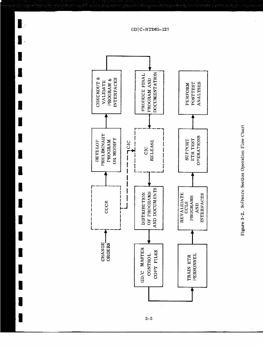
I
I
I
I
I
I
I
I
i
I
I
I
I
I
I
I
I
I
I
I
Z_
O0
GD I C-BTD65-127
II
_Ir !I Ii II ti
1 I ,I
I
_JIIII1
1,q Z
©
2:
1I
rD ,-1
= I!l
i
og
0<
l, ___._o_I, _, R$_ 0
I i
!
_OZ
raO
_z
0
hO
< _
_Z
z_
3-5
0
o°,-_
0
0
©
!

GDI C-BTD65-127
Each program will be prepared in conformance with its corresponding Specification
Document, which will present program design constraints, program accuracy require-
ments, function operations, and performance requirements.
The Program Description will consist of complete program listings, ranges of values
for variables, sets of working constants, special scaling and overflow protection
requirements, real-time data inputs and outputs required, description of basic ideas
behind the logic, and other information required to define the computer program.
A detailed program checkout will be accomplished before each program is released.
The program checkout plan will be defined in the Program Checkout Plan Document.
This plan will define the procedures to be used in checking out the program at GD/C
and ETR. Included in this plan will be:
a. Checkout equipment requirements.
b. Computational hand-checks list.
c. List of checks required for logic checkout.
d. Flow chart of checkout sequence.
e. Flow chart of functional checkout of program operation with interface equipment.
f. Input/output parameter specifications for checkout.
The Program Test Results Summary will summarize checkout results and provide
accuracy analyses as applicable. It will compare the results with the program speci-
fications. It will also summarize changes in the program and test plan procedure_C:l.q _.I"III_:_I[7('I/'_('_.11"I_ .
3.3 CONTROL AND RELEASE OF THE CCLS CONFIGURATION. Since there will
be only one CCLS, it is planned to document its configuration by making use of best-
commerical-practice drawings. These drawings will be adequate for all maintenance
and troubleshooting operations, and will allow the equipment to be duplicated if ever
required. They will not have the level of detail needed for mass production of equip-
ment, and hence will be obtained at a considerable saving. The minimum requirements
of this type of documentation are described in Appendix A.
Final release of CCLS configuration is planned after the set has completed the ETR
demonstration for vehicle AC-8. This allows any changes that may be required as a
result of the demonstration testing to be made with a minimum of paperwork. After
release, the normal GD/C change identification control number {CIC) procedure will
be followed to make changes to the equipment.
3-6
IIII
II
II
II
II
III
IIII

I
!
I
I
I
I
I
I
II
I
I
I
I
I
II
I
I
GDi C-BTD65-127
3.4 COMPATIBILITY OF THE H.M_.DWARE AND SOFTWARE, PREFLIGHT AND
INFLIGHT, AIRBORNE AND GROUND EQLrIP]_LENT. The method of maintaining
compatibility between the launch set and the airborne hardware and computer program
consists primarily of the procedure that _dll be employed to establish design and com-
puter program concepts. A very thorough documentation process will allow a thorough
review and reveal any incompatibilities between the CCLS program and hardware and
airborne system programs or hardware. This process will permit a review of the
design and program by members of the Error Analysis Committee and the Guidance
Equation Review Board (GERB) as deemed necessary.
GD/C considers that the design and computer program concepts of the C CLS will have
been established with the publication of this report. Prior to this report these prob-
lems were studied under Change Order 361. Design concept reviews were conducted
so that NASA inputs could be included. The concept agreed upon will not be changed
unless a new design or program concept is documented and reviewed. The final design
will be completed and documented in a Final Design Report. As was the case with the
design concept, the design will not be changed unless it is documented and reviewed.
The program will also be documented throughout its development. It is intended that
the same ts_pe of review process _ll assure program, as well as hardware, compat-ibility.
3.5 ETR PROCEDURES. A successful policy _ereby ETR procedures are written
by ETR personnel has been used in the past. With the introduction of the CCLS, the
problem of procedure writing will be compounded slightly by the fact that the procedure
will depend on the program in the ground computer. It is planned that guideline pro-
cedures will be prepared by the San Diego personnel who develop the program, but ETR
personnel will be responsible for the actual procedures used (they will adapt the guide-
line procedures to the checkout and launch test requirements and will document their
own procedures).
Most of the new procedures will not be as detailed as the present procedures, because
a typical operation will only require 4 or 5 basic operator decisions; the computer
will handle the routine sequencing. The area in which more extensive procedures
will be required has to do with aborts of tests and new diagnostic routines.
3.6 CONTINUOUS PARTS SUPPORT AND MAINTENANCE. Handling of parts sup-
port and maintenance for the CCLS will be through use of normal field service contracts
with SDS and DDI for servicing the equipment that they design. SDS equipment to
be maintained consists of the ATE-2230 and the disc with its Y buffer. The DDI equip-
ment includes the display control chassis and the three display consoles. Auxiliary
electronics being built-up by GD/C will be maintained by GD/C through normal spares
provisioning of the NAS3-3232 contract. Shortly after the design is finalized, engineer-
ing will provide a recommended list of spare parts to the spares group so that spares
can be ordered. All spare parts will be stored at ETR.
3-7

GDIC-BTD65-127
3.7 FAILURE ANALYSIS. Failure analysis of the SDS-furnished hardware will be
conducted by SDS engineering personnel. A failure analysis subcontract work state-
ment will be negotiated with SDS before the ATE-2230 is delivered. Failure analysis
of all other parts of the CCLS (including the display) will be conducted by GD/C engi-
neering personnel. All failure analysis results will be documented in a formal failure
diagnosis, two copies of which will be presented to NASA within 60 days after the failure.
3.8 PROGRAM IMPLEMENTATION SHCEDULE. The present plan is to conduct a
computer-controlled guidance launch set demonstration on AC-8, and launch the next
vehicle using the CCLS.
The task of integrating the CCLS into the blockhouse for AC-8 requires a careful pro-
gram plan to assure that schedules will be met. At this time, the schedule of hard-
ware delivery is shown in Figure 3-3. This schedule will allow the ETR modification
task to be completed by 30 October 1965, in time for the AC-8 demonstration.
The schedule of documentation includes a Final Design Report and an Opera-
tion and Maintenance Manual on 31 December, Final Program Documentation Reports
about two weeks prior to the start of checkout of any vehicle at ETR, and Program
Concept Reports as indicated by the program development schedule that follows.
a. Preparation of test requirements documentation for AC-8 by 15 September.
b. Preparation of the preliminary subroutine tree structure 15 August.
c. Begin coding principal subroutines forATE-2 on 30 July.
d. Preparation of program specification for AC-8 complete by 1 October.
e. Begin demonstration of subroutines on ATE-2 on 15 August.
f. Begin checkout of programs on the SDS 930 computer less disc on 15 October.
g. Complete demonstration less disc by 1 December.
h. Program description for AC-8 complete by 1 December.
i. Preparation of test requirements documentation for AC-10 by 1 December.
j. ETR demonstration complete by 1 January.
k. Program specification for AC-10 complete by 1 January.
1. Programs for disc delivered to ETR on 30 January together with disc.
m. Disc integration complete by 28 February.
n. Test descriptions for AC-9 and on six months prior to start of checkout at ETR.
o. Program specifications for AC-9 andonfive months prior to start of checkout atETR.
p. Program descriptions for AC-10and on two weeks prior to the time checkout begins
at ETR.
3-8
I
II
III
II
II
II
II
I
III
I

I
I
I
I
II
I
I
I
I
I
I
I
II
I
II
I
@
JPL
@
@ START @ J-PL MPLAY @
P_tOCURE COMPUTER (FACILITY CONTRACT)
@ PROCURE AUXILIARY ECECTRONICS Q
TEST _ PRECODINGREQUIREMENTS PROGRAM
Q DOCUMENT Q SPECIFICATION
953-3
PERT START_
PATCH RACK_
AND COMPLEX
36B CABLES
953-3
& PERT START_
COMPLEX
36A CABLES
989-3
D_GN TO ABM
989-3 423-1 744-t
/ _P_REC_LE'CO_! ',/ _.o----------------_2.0 K_ 6.0 \
PROCURE CABLE & CONNECTOR
989-3 989-3
DESIGN _ INSTALLATION DESIGN
TO ABM /_
/ I 832-1 8oo
Z. 0
PROCURE PATCHRACK
®423-1
PLANNING
800 90-05589-00!
PROCURE PATCHRACK
13.0
989-3
DESIGN TO ABM
989-3 423-1 744-(
FINAL DESIGN _ PLANNING
//_ 6.0 _ 2. 0 _ABLES
/ _ P_OCU_EDE_,"_I _/ 1. o_.../ z. o _,._.,/ e.o
I 9.o/PROCURE DETAILS

GD I C-BTD65-127
PROCURE DISC
BEGIN|
1/5 _ AC-8 ETR C/O
i
END
$I
PROCURE INSPLAY
_ VALIDATE
PROGRAM
_ ASSEMBLE ,: VALIDATE
_ PROGRAM
ASSEMBLE ELECTRONICS
CODE & DEBUG ON 910
PROGRAM DESCHIPTION
TE
835--4 C.O. 589
TO ETR ,_Ins_'_
1.0
835-4 C.O. 589
TsTE0_ _IIP TO ETR1.0
2/1) SHIP TO ETR O
,)
VALIDATE
PROGRAM )VALIDATE &PROGRAM
Figure 3-3. Preliminary CCLS Schedule
GD i C-BTD65-127
SECTION 4
IMPLEMENTATION OF COMPUTER-CONTROLLED CHECKOUT
The requirements imposed upon the CCLS and the techniques to be used to fulfill these
requirements have been generally described. This section presents a detailed des-
cription of the hardware and software that will be employed in the final configuration
CCLS. Such items as the programming languages, the program control technique,
and the hardware design concept will be investigated. Timing and procedural require-
ments will be identified, and problems requiring solution will be listed and discussed.
4.1 THE EXECUTIVE CONTROL TECHNIQUE. The requirements imposed upon
the executive program can be summarized by the following:
a. The executive program must control the test sequence by calling subprograms
that cause control and monitoring functions to be performed by the computer.
b. The executive program must include a provision for the operator to enter the
decision-making process.
Co The executive program must allow several tasks to proceed in a time-shared
manner, by assigning priorities to the various subprograms. For instance, the
data processing activities must proceed simultaneously with calibration. If the
machine is to ever be used for autopilot checkout as well, it must control both
guidance and autopilot at the same time.
In order to control the various subprograms, a table will be contained within the exe-
cutive program. This table will list the subroutines to be accomplished during the
test sequence, in the order in which they are to be accomplished. Every subprogram
will have a priority assigned to it by the executive program. In case of real-time con-
flicts, the highest priority subroutine will be executed. Subprograms may contain both
higher and lower priority sections. The programmer must, at the time of coding a
subroutine, determine what priority the program will have at any given execution time,
and must so instruct the executive program.
The executive program priority system must ensure that a compute cycle time that is
commensurate with maintenance of control over the guidance system is retained. In
order to accomplish this, the executive program may have to delay the execution of
low-priority programs. Duty cycle will also be considered by the executive program.
The execution of a low-priority program may be time shared with that of a high-
priority program, ff the high-priority program's duty cycle is small. In determining
duty cycle timing, the longest unserved interval that any subprogram can have will be
used as a criterion.
4-1
GD[C-BTD65-127
The highest priority programs will use priority interrupts to ensure that they are exe-
cuted immediately. Programs of this type include those that protect the equipment
from damage, those that take over control of the ground computer ff the input power
to the computer is lost, and those that service input/output devices. The middle-
priority programs are those that must be executed in real time (time is crucial to
their operation). Programs of this type include:
a. Data handling programs - since the machine must process data in real time if
none is to be lost.
b. Sequencing programs - programs that check out the autopilot timer or interface
with logical timing circuitry.
c. Calibration programs - where sampling of data must be controlled on a real-time
basis.
The lowest priority programs are those that provide after-the-fact evaluation of data,
in which real time is not important.
4.1.1 Example of Executive Control. Executive control will be accomplished using
the display system to provide a numbered list of control options that may be exer-
cised by the operator. If the operator enters a number that corresponds to an option
contained in the list, and subsequently depresses the keyboard SEND key, the program
will be instructed to immediately branch in accordance with the new control choice.
A typical control sequence, which could be used by the operator, to vector (control)
the program, follows.
The first-level display could take the following form:
001. DIAGNOSTICS
002. FUNCTIONAL TESTS
003. CALIBRATION
004. MODE SELECT
005. READ DATA
006. REMOTE LOAD AND READ
007. POWER TURN OFF
If the operator wished to perform any functional test, the number 2 would be entered on
the keyboard, and the SEND key would be depressed. Data transfer to the SDS memory
would then take place. The program would sense the selected function and would output
a second-level display of operator options. These could include:
4-2
kl
L
I
II
II
II
III
I
II
III
I

I
III
I'I
II
IIl
II
l
lI
II
GD i C-BTD65-127
001.
002.
003.
004.
005.
006.
COMPUTER TEST
ACCELEROMETER LOOP TEST
GYRO LOOP TEST
GIMBAL SLEW TEST
EARTH SPIN TEST
POWER TURN OFF
If the operator wished to run a computer test, he would enter the number 1 on the dis-
play keyboard, and then depress the SEND key. A third-level option choice would then
appear:
001.
002.
003.
004.
005.
006.
COMPLETE COMPUTER TEST
MEMORY CHECK
COMMUNICATION MODE
DISCRETE OUTPUT CHECK
TELEMETRY CHECK
POWER TURN OFF
The operator's selection of one of these options will initiate the performance of thetest.
Operator choice specifications will always be displayed as soon as the corresponding
key is depressed, but will not be input to the computer until the SEND key is depressed.
Errors can, therefore, be corrected by the operator editing the message. Mistakes
that have been transmitted to the computer can be corrected by revectoring through
the choices. The vectoring process would take several minutes to perform if a type-
writer were used. However, with a CRT-type display, the complete vectoring to a
detailed test should not require more than a few seconds.
4.1.2 Out-of-Tolerance Data Handling. The executive routine, together with the
display system, must handle and inform the operator of out-of-tolerance conditions
{OTC's} as they arise. For the purpose of this report, OTC's will be categorized as
either a situation which demands an automatic, preprogrammed response to avoid
possible catastrophic failures, or a situation which may be handled by the operator on
a nonexpedited basis. In general, the display of out-of-tolerance conditions will betreated as follows:
a. The OTC data will be displayed less than 100 milliseconds from the time it occurs.
b. If the computer changes the system test status to automatically process an OTC,
the new test condition as well as the OTC data will be displayed.
4-3

GD IC-BTD65-127
In order to examine certain out-of-tolerance conditions it may be necessary to enter
a special, program-controlled, high frequency data logging mode. Since this is a
diagnostic type activity, the CCLS will output the high sampling rate data to a strip
chart recorder through a digital-to-analog converter. This will allow data display at
frequencies up to 60 CPS, which is adequate for most guidance system signals. The
recorder will be controlled by the operator in accordance with instructions on the dis-
play tube face for selecting channels, gains, and paper speeds. Signals with a fre-
quency response exceeding the capability of the strip chart recorders will be sampled
by special circuitry having adequate response, or by the operator with an oscilloscope.
Display tube outputs of OTC's will be in a flashing mode to attract the operator's atten-
tion. Several such conditions can be displayed at once. A reasonable format for this
type of display (an out-of-tolerance +35VDC is used as an example) could appear as:
+ 35VDC = +xx. xx
ULIM = +yy. yy
LLIM = +zz.zz
ET = abcd
where ULIM and LLIM are the upper and lower in-tolerance limits, respectively, for
this measurement and ET is the elapsed time since the first discrepancy. ET will
cease changing and reset when the out-of-tolerance condition ceases to exist for five
seconds. This output can be cleared by the operator.
At the same time that they are being displayed, OTC data will be stored on magnetic
tape at the rate at which it enters the CCLS. To prevent unreasonable waste of mag-
netic tape(due to high-frequency data logging), the operator will be allowed to select
a program option that will cause the data to be sampled at a lower rate. This mode
will cycle between sampling the data first at the high rate for 10 seconds, and then
at a slower rate for the next 50 seconds.
The operator may also add any data to the high-frequency data logging process by a
software request. Magnetic tape data logging of out-of-tolerance conditions will be
terminated by the program whenever the OTC ceases to exist for a period of five
seconds. In general, once an OTC is detected, it is presumed that the test will be
discontinued until the problem is corrected. Outputs to magnetic tape will be recorded
in record lengths of at least 2000 words, along with proper timing words so the data
can be time-correlated when it is reduced.
When an out-of-tolerance condition is detected that demands a fast response time to
prevent possible damage to the system under test, the computer will automatically
vector to the proper service routine to perform the required control action. Assuming
4-4
1 I
I
III
II
I!I
II
II
III
I

I
I
I
I
I
I
I
l
I
I
I
I
I
I
I
I
I
I
GD !C-BTD65-127
the problem is within the guidance system, the program will take those actions neces-
sary to avoid a catastrophic condition and will then output a message to the display to
indicate program status, and what parameter malfunctioned. If the action taken by the
computer did not require any power to be removed from the guidance system, the high-
frequency data logging process will sample the malfunctioned parameter until the
operator terminates this process, or the parameter returns to its normal state for at
least five seconds.
4.1.3 Format of the Display. The executive program must display the status of
system checkout at all times. The operator of the present GSE knows that the guidance
system is, for example, in a particular calibration mode, by observing the position of
the align mode switch; the phase progression of the align mode can be recognized by
observing the gyro torquing traces on the Sanborn recorder. The CCLS will display a
comparable amount of information, including the phase time, as the functions are
taking place, in alpha-numeric form.
Phase time will be updated approximately every second. Figure 4-1 shows a prelimi-
nary sectionalization of the CRT display face. Table 4-1 indicates a typical set of two
lines of display message that might be seen.
4.2 PROGRAMMING LANGUAGES. The task of programming a computer to solve
a particular problem must be accomplished quickly and accurately. The language that
the programmer uses can affect both the accuracy and speed of programming.
There are two steps involved in any programming task: analysis, which includes des-
cribing the problem and building a mathematical model, and coding, which includes
the translation of the model into a sequence of machine instructions. For example,
the statement "Let A be the sum of B and C" is represented by the mathematical model
A = B + C which, for an SDS 910 computer, can be translated into the following sequence
of machine instructions:
07601000
05501001
03501002
It can be seen that the most tedious, time consuming, and unreliable part of the pro-
cess will be coding the program into machine language. As a result of the complexity
of the coding operation, two types of automatic programming systems, called assem-
blers and compilers, have evolved.
The assembler is correlated to the computer program in a one-to-one relationship
(for every single instruction coded by the programmer, the assembler will furnish a
single machine instruction). Since the computer industry supplies many types of com-
puters, each with a different instruction repertory, many assembling systems have
come into being.
4-5

r.,.l
c,,1
w II v
A
ooL_
O0
GDJC-BTD65-12,7
r_
Z
t_A
T
r$1
Z
A
Z
Z
z
D
I r
Z
oI--I
i A
Z0
Z0o"
o
O
!
©I
O
Ar$1
Z
o
4-6
m0
m
o
r_P_"I
r_
oo
_u
°_,,,I
O
O
o
r_
b
I
I
I
II
III
II
III
I
III
II
II

I
I °_
I °
I °O
I °!
°__o__D
_D
OO
1"'4
ZO0
O<_m
r.r.l
_m
0_0
_ ,
r_
_ z
GD 1C-BTD65-127
4-7

GD IC-BTD65-127
A compiler is correlated to the computer in a one-to-many relationship (forevery sin-
gle instruction coded by the programmer, the compiler will furnish many machine
instructions). This type of system allows the programmer to communicate with the
computer in an algebraically-oriented language.
4.2.1 Assembling and Compiling. The detailed coding, in both assembler and com-
piler programming systems, is actually done by the computer, using the assembly or
compiler program. The programming task is begun, when using an automatic pro-
gramming language, by generating a source program which consists of a series of
statements written in the automatic language format. This format is closely related
to the terms in which an engineer or mathematician thinks. When the source program
is completed, the automatic programming language enclodes it into a series of ma-
chine language statements, called the object program. It is the object, or machine
language program, that finds the solution to the problem coded by the programmer.
Normally a programmer will select a compiler or an assembler depending upon the
problem being programmed. In programming the SDS 930 computer of the CCLS there
is a need for both an assembler and a compiler. A single system that incorporates the
combined characteristics of both could also be used.
There are several automatic programming languages presently available from the SDS
program library, and several others in development. The status of each of the lan-
guages of interest is shown in Table 4-2. The columns containing compatibility infor-
mation indicate whether or not a program can be coded for one test set (i. e., the
ATE-2) and be run on another set (i. e. the ATE-2230).
Table 4-2. Programming Language Development Status
I
II
III
iI
III
LANGUAGE
NAME
Symbol
FORTRAN H
Real Time
FORTRAN ]1
Meta-Symbol
ATOLL
TYPE
Assembler
Compiler
Compiler
Assembler
Compiler
AVAILABILITY
FOR USE ON
ATE-2
Available
Available
Sept 1965
Never
Not Available
ATE-2230
Available
Available
Aug 1965
Available
Not Available
COMPATIBILITY
ATE-2 TO
ATE-2230
Yes
Yes
•Yes
No
ATE-2230
TOATE-2
No
Yes
Yes
No
4-8
I
III
I
III

!1
II:
!
!
I
I
'|
!
I
I
I
I
i!
I
,II
f
i
I
GD IC-BTD65-127
4.2.1.1 Symbol Assembler Characteristics. The Symbol assembler is a two-pass
system (a system which requires the loading of the source program twice before the
assembler can supply an object program). Table 4-3 shows a Symbol source program
and its equivalent machine language object program.
Several definitions are required prior to ex_minin_ the detailed operation of the
assembler:
a. A symbol is defined as any combination of one to six alphanumeric characters, at
least one of which is alphabetic.
b. The location address field is a symbolically coded list of the operands used in the
program.
c. An operation is defined as any combination of four or less alphabetic characters
which specify a particular machine instruction.
d. The variable field of an instruction is the space provided for the symbolically
coded identifiers that are assigned during the first pass.
e. The source program is the program that the programmer writes to solve a particu-
lar problem.
f. The object program is the listing of machine instructions that the assembler
generates in response to the source program.
The first assembly pass reserves an absolute machine address for each instruction in
the program, and assigns an absolute machine address to each symbol of the location
address field. The second assembly pass substitutes the correct absolute machine
address (assigned during the first pass) for any symbolic expression used in the
variable field of the instruction. The entire instruction, including any indirect address-
ing and tagging, is assembled during the second pass and output on paper or magnetic
tape in the format specified by the user.
The source program may be enteredby paper tape, cards, magnetic tape, or type-
writer. The Symbol assembler will also list the object program and the source pro-
gram at the operator's choice. The absolute machine address of each machine word
is Listed adjacent to the machine word Listing. Certain errors that are detected by
the assemblerts built-in diagnostics are indicated by special symbols during the listing
of the program.
In order to develop a program with Symbol, the programmer must be familiar with the
complete set of machine instructions. This allows the full use of the capabilities of
the SDS 930 computer. All the machine instructions with tagging and indirect address-
ing can be commanded directly in the symbolic notation, relieving the programmer of
4-9

GD IC -BTD65-127
FORTRAN II object programs. This implies that the fail-safe power interrupts can-
not be used when executing a FORTRAN H object program.
Interlacing of input/output data is not handled directly by FORTRAN II. The implica-
tion is that the use of a standard input/output device such as the typewriter will monop-
olize the SDS computer completely during any input/output operation. (No instructions
can be executed until the input/output phase is completed. )
The execution time of a program is an important consideration in choosing an automatic
language. The execution times of FORTRAN II object programs are often long com-
pared to equivalent Symbol object programs. FORTRAN II was written for programming
ease rather than for execution speed. This loss of execution speed is acceptable in
most circumstances. However, when the programmer is dealing with time-dependent
input/output and real-time command and control, the timing becomes crucial. This is
the case, for example, when coarse alignment of the guidance system is taking place.
When execution speed is essential, Symbol subroutines are needed to solve the problem.
The necessity to transfer continuously between FORTRAN II and Symbol subroutines is
a handicap to the programmer as far as development time and debugging the program
are concerned.
4.2.1.3 Real-Time FORTRAN H. The development of Real-Time FORTRAN II
remedies many of the objections to standard FORTRAN H. In addition to having the
same capabilities as FORTRAN II, Real-Time FORTRAN II has several advanced pro-
gramming features. Interrupts can be used during the execution of object programs of
this new system. This provides power fail-safe interrupt capability at all times.
Interrupts also allow the use of input/output operation interlacing. Symbol statements
within a FORTRAN H program can be processed by the new compiler. This eliminatesL'O _ _ 1_--1
4-1,.. _y niuum,,e need for - *: .....'--uon,_nuuu_Ly transferring between FORTRAN and sub;_outines.
Also, this compiler can process FORTRAN logical statements (AND, OR, NOT). The
capability, in combination with the use of Symbol statements within FORTRAN, provides
a powerful tool for writing logical programs. The timing difficulty can be handled
simply by using Symbol statements within FORTRAN or by using Symbol subroutines
as the situation demands.
4.2.1.4 ATOLL {Acceptance Test or Launch Language). The ATOLL language is an
automatic space vehicle checkout language selected by NASA (MSFC) to be the standard
language for missile checkout at MSFC. Mesa Scientific Corporation {MESA) is pres-
ently in the process of developing this language for MSFC. Since it is not yet completely
developed, there are no immediate plans to use ATOLL in the ATE-2230 system. When
it becomes available through either MESA or SD$, it will be considered for use.
4.2.1.5 Meta-Symbel Assembler. It is desirable that all programs developed for the
ATE-2230 be capable of cycling on the ATE-2 for checkout purposes. Languages in
which the programs are written will have to be compatible with both the SDS 910 com-
puter (a part of the ATE-2) and the SDS 930 (a part of the ATE-2230). Since the
4-12
|i
!
I1
I]
I]
II
I]
It
II
I/
I1
I!
i]
II
I1

II
III
II
II
I
III
I
III
GD[C-BTD65-127
Meta-Symbol assembler is not projected to be available for an 8000-word memory
SDS 910 computer {the present ATE-2 configuration), the use of Meta-Symbol is pro-hibited and will not be discussed further.
4.2.2 Development of Operational ATE-2230 Programs. It has become quite clear
that the combined use of FORTRAN II and Symbol will be required to implement com-
mand and control of the guidance system efficiently. The following set of ground rules
has been devised as a guide for the development of operational programs.
ao The control program is to be written in Real-Time FORTRAN H. The operator
will command all tests from the control program which will have the ability to
call all subprograms from core or disc file memory.
b. Algebraic problems will be written in Real-Time FORTRAN II. This includes the
solution of the guidance preflight equations and other mathematical calculations.
Co Standard input/output routines will be written in Real-Time FORTRAN H. This
includes control of the typewriter, paper tape reader and punch, card reader,
and magnetic tape.
do Special input/output operations will be written in Symbol and will be either com-
piled by Real-Time FORTRAN H or assembled by Symbol. The choice will be
made by the programmer and will depend upon timing considerations and pro-
gramming convenience. The special input/output devices include the multiplexer,
analog-to-digital converter, digital-to-analog converter, one-shot relay drivers,
special input/output buffers and special display buffers.
e. Boolean expressions can be written in Real-Time FORTRAN II or Symbol, depend-
ing on the nature of the problem to be programmed.
4.3 THE ATE-2230. The ATE-2230 has, as its central processor, a SDS 930 com-
puter with 12,288 words of 24-bit core storage. The test set is also equipped with
certain special features that make it suitable for real-time control of a launch/checkout
operation. Among these features are priority interrupts (32 are provided), single bit
sense inputs, single bit pulse outputs, 24-bit parallel inputs and 24-bit parallel outputs.
4.3.1 Priority Interrupt System. Priority interrupts are signals which can be used
to interrupt the execution of the main program in order to provide service for a device
which is physically external to the computer memory, and is operating asynchronously
with respect to the memory. The presence of a priority interrupt signal causes the
computer to complete the execution of the instruction it is performing at the time of
the interrupt and then, unconditionally, branch to a fixed memory location associated
with the particular interrupt that occurred. This memory location will always contain
the first instruction of the subroutine written to process the interrupt. Assume that
one of the delta-V counters detected a missing bit. The counter will cause a signal
4-13

GDI C-BTD65-127I
to be generated that will be sensed by the computer as a priority interrupt. The serv-
ice routine will include an automatic display consisting of words to describe the condi-
tion (missing bit) and the location (u, v, or w). The interrupt service routine will
also display the control action choices available to the operator, (i.e. continue, stop,
call diagnostic program).
Assuming that the operator decided to execute the "continue" option, the computer
would then return to the program it left to service the interrupt. The return would
be accomplished such that the next logical instruction, assuming the interrupt had
not occurred, would be executed.
The program is provided with two means of control over the priority interrupts: arm/
disarm and enable/disable. The enable/disable instructions operate upon all 32
interrupts at one time, and determine whether or not interrupts will be processed.
If the stimulus for an interrupt occurs, but the interrupt system is disabled, the in-
terrupt system will "remember" the stimulus and will cause the associated interrupt
to be processed once the interrupt system is enabled. The arm/disarm feature pro-
vides capability to selectively allow only certain interrupts to be sensed by the central
processor. A disarmed interrupt whose stimulus occurs will not be sensed and will
not be "remembered." The interrupt system assigns a fixed priority to all interrupts.
Execution of the subroutine associated with any interrupt may be suspended if an
interrupt of a higher priority occurs.
III
II
II
II
In addition to the system interrupts that have been described and are available for
general purpose usage by the system designers, the CCLS also contains higher priority
interrupts associated with power fail-safe, system clock, and standard peripheral
cquipment control. None of the higher priority inter_apts contain the arm/disarm
feature. All but the power fail safe interrupts may, however, be enabled or disabled.
Interrupt signals must, to ensure recognition, be +8VDC in amplitude, and must have
a 1.75 microsecond (minimum) duration.
4.3.2 Single Bit Input and Output. The ATE-2230 central processing unit contains
a single bit input instruction which, like the interrupt, allows the program to operate
in a real-time mode, monitoring external hardware. Unlike the priority interrupt,
the SKS can sense a high or low external signal only under program control, and con-
tains no arm/disarm or enable/disable feature. Execution of this programmed instruc-
tion allows the program to proceed to the next logical instruction if the external signal
is set (+6.0 to +20.0VDC), or to the next logical instruction plus one if the external
signal is not set (-2.0 to +2.0VDC). The central processor contains capability for
sensing up to 128 different external signals using SKS instructions.
The ATE-2230 also provides, under program control, single-bit outputs of +8VDC
amplitude and 1.75 microsecond duration. These outputs are called EOM's, (Ener-
gize Output Module) and may be used by the system designer for such tasks as resetting
counters, enable inputs, triggering relay drivers, etc. The ATE-2230 contains pro-
vision for 256 EOM's of which 36 are reserved for standard peripheral device control.
4-14
I
I
III
I
III

°
II
IiI
iI
Ii
II!
II
i
III
GD t C-BTD65-127
4.3.3 Parallel {24 Bit) Input or Output. The central processing unit contains capa-
bility to either input or output entire computer words (24 bits) by use of the parallel
input (PIN) or parallel output (POT) instructions. Gating that accompanies these in-
structions allows for twelve different PIN's and twelve different POT's. Typical
usage for the instructions might be to transfer the contents of a delta-V counter into
memory (PIN) or to transfer the contents of a memory cell to the mode line output
buffer (POT).
4.3.4 Data Multiplex System. The Data Multiplex System, shown schematically in
Figure 4-2 is the facility that will be employed to either selectively or continuously
monitor all guidance system analog outputs. Three basic modes, or capabilities, are
contained within this section of the ATE-2230:
MODE 1 - In a serial manner, digitize each analog signal and store the result in a
fixed location in memory. When all 128 analog signals have been digitized
and stored, issue a priority interrupt and repeat the sequence. In this
mode a data table with 128 entries is built up and continually updated.
This mode shall, henceforth, be referred to as the "spin mode. "
MODE 2 - Select a specific piece of analog data and continually digitize this signal.
Store the result in a data table having 128 fixed locations in memory
(the same locations as in Mode 1). When 128 values have been stored,
issue a priority interrupt signal and repeat the sequence.
MODE 3 In a serial manner, digitize, once only, a selected set of analog signals,
and store the results in a block of memory designated by the program.
The number of conversions (analog-to-digital) shall in this mode be be-
tween one and 128, as specified by the program. Upon completion a
priority interrupt will be issued. This mode is referred to as the standard
internal interlace mode in the SDS literature.
The Data Multiplex System contains two basic elements: a Data Multiplex Channel for
communicating and synchronizing between the data source and the memory, and a Data
Subchannel II for interfacing between the DMC and the analog-to-digital converter.
The DMC contains a 15-bit address register and a 25-bit data register that gives it
capability of reading out the internal interlace memory location specified by the DSC.
Having read this information out, the DMC then increments the address portion of the
interlace word, decrements the word count portion, and restores the modified word to
the interlace location. The data information is then accepted from the DSC and is
stored in the memory under control of the DMC. If the word count, when decremented,
was zero, the DMC will so signal file DSC, thereby causing the DSC to issue a priority
interrupt signal to the computer main frame. The Data Subchannel H contains those
controls necessary to provide the DMC a hard-wired signal containing the location of
the memory interlace word and provide a zero-word count priority interrupt to the
computer.
4-15

GDI C-BTD6 5-12 7
4K
MEMORYMODULE
MU LTIP LEACCESS TO
MEMORY
DATA
MULTIPLEXCHANNEL
I
DATA
SUBCHANNE LII
DATA
SUBCHANNEL
II
ANALOG-TO- i CENTRAL
CONTROL
DIGITAL I UNITCONVERTER
titMU LTIP LEXER
TANALOG DATA
I IISPLAYNO. 1
I DISPLAYNO. 2
DISP LAY
NO. 3
Figure 4-2. Second Path to Memory Display and Analog Data Handling
4-16
I
!
III
II
II
II
III
I
III
I
i:
III
I
iI
IIit
II
i
i
I
Ii
GD ]C-BTD65-127
Modes 1 and 2 will be commanded by issuance, under program control, of two EOMts
and one POT instruction. These commands will serve to alert (initialize) the multi-
plex unit and the DSC-II, enable an external data address location register, and select
the starting channel of the multiplexer. These commands also serve to either enable
(in Mode 1) or disable (in Mode 2) continuous stepping of the multiplex unit. A third
EOM will be employed to stop the multiplexer and end the filling of the data table.
Mode 3 will be commanded by issuance, under program control, of two EOM_s and two
POT instructions that will serve to alert (initialize) the multiplexer and DSC-H and
enable the internal interlace mode of operation. The program will also be required to
specify the first location of the data table to be constructed as well as the total number
of table entries.
Operations involving use of the Data Multiplex System for analog data retrieval are
limited, with respect to speed, by the capability of the analog-to-digital-converter-
multiplexer combination to approximately one sample every 50 microseconds, or
20,000 samples per second.
Mode 1 is provided primarily to allow the main program and the data accumulation to
independently proceed at maximum rates. Data entries in the data table formed in
this mode are, at most, five milliseconds old at any given time. The programmer
always has the option, in this mode, of limit-checking all, none, or selected data
entries.
Mode 2 is provided to allow the programmer to examine, in detail, any one signal of
the 128 possible inputs. Approximately 20,000 samples per second of the signal of
interest may be made in this mode.
Mode 3, the standard internally interlaced mode of operation, is provided to allow the
programmer still more flexibility in detailed examination of signals. In this mode the
programmer may repeatedly, under direct program control, sample any number of
channels, in any order. The digital results may be stored in any desired location.
This facility allows the programmer, for example, to repeatedly sample five adjacent
multiplex channels much faster than is provided in Mode 1 - a capability that may be
found desirable in diagnostic testing. There are, however, two facts that relegate
the Mode 3 operation to a diagnostic, rather than a general-purpose, data-gathering
tool:
a, The programmer must exercise considerably more control over Mode 3 than
Mode 1, especially when he is gathering data from nonsequential multiplex chan-
nels. He must change the internal interlace word each time he calls an out-of-
numerical-sequence quantity.
b. Data storage in Mode 3 requires that the 4K memory module be tied up (unacces-
sible by the main program) for three machine cycles or approximately five
4-17

GDIC-BTD65-127
microseconds, per data quantity to be stored, whereas operations in Mode 1
require a tie up of only one (1.75 microseconds) machine cycle per data quantity.
4.3.5 Display System. A display system is included in the CCLS. It will be
employed to:
a. Keep the operator and test conductor informed of the status of the test in progress.
b. Present to the operator the choices available when a human decision is required.
c. Make available a facility for the operator to communicate his decisions or queries
to the computer without totally tying up the central processing unit.
The system that was chosen to perform this task is the Data Display Model DD-10
equipment. It includes a central control unit, capable of retaining and refreshing in-
dividual messages for each of its displays, and three data display/entry stations, each
capable of displaying up to 1000 alpha-numerics. Each display/entry station has its
own keyboard and independent SEND key, such that the operator may compose mes-
sages in an off-line manner, and then transmit them to the computer at a rate commen-
surate with the computer's ability to receive. The display refreshing capability, con-
sisting of a 1000-character delay line for each display unit, is contained within the
display system central control unit. Thus, the computer is relieved of the burden of
continually sending the same display message (typically, 60 times per second would be
required) in order to keep the display illuminated.
The data display system operates in a manner similar to Mode 3 (internal interlace)
of the data multiplex system. A display message is contained within the computer's
4096-word memory bank at all times. Additions to, or deletions from this basic mes-
sage are made under program control. Once a new message has been formatted, the
program will required to issue control signals consisting of an EOM and a POT that
will cause the display system to be accessed (connected) to the second path to memory.
Having established the connection, the display message will be transmitted from the
memory, through the DMC, to the DSC-II and then to the display central control unit for
output to the display tubes. The data transmission takes place under internal interlace
control. (The program must specify to the internal interlace word location the number
of words to be output as well as the location of the first word to be output.) The DMC
will then access the interlace word, and control the data transmission.
Figure 4-2 indicates that there is only one second path to memory feature that is
used by both the data multiplexing and display systems. Since the two systems operate
asynchronously, both with respect to each other and with respect to the memory, it is
conceivable that the data system will at some time, attempt to input data to the memory
simultaneously with an attempt by the program to output a display message. Thus, a
very definite need existed to assign a priority and control scheme to the operations
concerned with the second path to memory.
-.I
!
i
I
iI
I
I
I
[
i
4-i 8 ,

:
I
lI!!iI
II
IIIiI
i
III
GD[ C-BTI_5-127
The highest priority has been assigned to the data multiplex system, in order to ensure
that no data is ever lost. The implication is that in the event of conflict, an input from
the data multiplex system will delay a display output by a maximum of three machine
cycles (five microseconds). If an output to display sequence is interrupted by a higher
priority data storage request, the data storage request will be honored, and then the
output to display will automatically resume.
Operator input to the computer, via the display keyboard is automated by use of the
keyboard SEND key which, when depressed, sends a priority interrupt signal to the
computer. The service routine for this interrupt will store, in the internal interlace
word location, a word containing the number of words to be input and the first location
of the block of memory to be filled. The routine will then send two control instructions,
an EOM and a POT, to the DSC-H in order to command it into a computer input mode.
The DSC-II will then control the data transmission between the display's central control
unit and the SDS memory.
4.3.5.1 Selection of the Display. Numerous display systems were evaluated in an
attempt to make a final selection of the unit to be incorporated in the CCI_. A com-
parison of characteristics of the three units th-t were to receive final consideration
is shown in Table 4-4. The following ground rules were applied in making the choice:
a. Physical size - no direct requirement except insofar as readability is affected.
b. Character writing time - shortest is most desirable.
c. Character storage - approximately 1000 characters very desirable.
d. Refresh rate - visual requirement is approximately 30 CPS minimum, with self-
contained refreshing (independent of program) very desirable.
e. Maximum frame size - 1000 characters minimum.
f. Vector generation - desirable, but not mandatory.
g. Bits per character - smallest number such that display message stored in core is
small.
h. Typewriter mode - desirable since this will be standard mode of output, and re-
quires less control.
i. Light pen - a desirable feature, but may be replaced by a decimal keyboard.
j. All silicon circuitry - very desirable.
4-19

GDI C-BTD65-127
Table 4-4. Display Selection Summary
DDI SDS SC
Physical Size 3 19-inch Racks* 1 19-inch Rack 4 19-inch Racks
Character Write Time '16.8 ms 50 ms 50 ms
Character Storage 1000 Character None Core Pack
Delay Line
Refresh Rate 60 CPS 60 CPS 20 CPS
Max. Frame Size 1000 Character 340 Character 1024 Character
Vector Generator No Yes Yes
Bits/Character 6 24 24
Typewriter Mode Yes Yes Yes
Light Pen No Yes Yes
Keyboard Yes No Optional
Silicon Circuits Some All Either
Input Mode Interlace Once Interlace 60 CPS Interlace Once
Delivery 9/25/65 In Development 9/25/65
* Each 37 inches deep + 3 desk top displays, 15 3/4 inches x 15 1/2 inches ×
24 inches each.
;I
IIIi
II
II
IIi
k. Input mode - desirable to use interlace, and only input when a change must be
made - it is not desirable to program control the refreshing.
° Deliver - desired for integration at GD/C on 9/25/65 - can be stretched to inter-
face at ETR on 12/1/65.
It was found that the DDI display met more of the requirements than the others. The
SDS display, while potentially a desirable one, does not yet contain its own buffer
storage, and has yet to be delivered to any customer, although promised delivery dates
are compatible with the CCLS schedules.
4-20
!!
!
GDI C-BTI_5-127
4.3.6 Digital-to-Analog Converters. Eight channels of digital-to-analog converter
outputs are provided in the ATE-2230. Each converter accepts 11 bits of magnitude
information and one sign bit. Each converter is provided with two flip/flop registers;
RANK 1 is used for assembling and temporarily holding information prior to conver-
sion, and RANK 2 is used to hold the same information during conversion. The dual
register capability allows the programmer to first load each of the RANK 1 registers
with data, and then to command simultaneous conversion on all channels by causing a
simultaneous data transfer from all RANK 1 registers to all RANK 2 registers.
The sequence used to load each RANK 1 register uses an EOM and a POT instruction,
where the EOM sets up the gating to properly route the output signals that will follow,
and the POT commands a parallel transfer from a specified memory location to the
qualified set of RANK 1 flip flops. A second EOM will be used to command the encode
sequence. Each time this command is issued, all converters will transfer information
from RANK 1 to RANK 2 registers. Only those registers whose data has changed since
the last conversion will undergo a change.
Digital-to-Analog converters require seven microseconds, once commanded, to per-
form a conversion and to have the analog output settle to within 0.01 percent of final
value. The mechanization of the convert command allows all eight converters to oper-
_tte simultaneously. Full scale outputs are :_10V, 20-mflliamps continuously. Accu-
racies are specified as follows for each converter:
a. Ma_rimum offset error = 0. 025 percent of full scale.
b. Maximum standard deviation = 0.03 percent of full scale.
4.3.7 Time-Multiplexed Communication Channels. The ATE-2230 is provided with
two time-multiplexed communication channels (TMCC's) that permit bidirectional
information transfer between a variety of input/output (peripheral) devices and the
memory. The mode of transfer is character parallel, with parity bits. One of the out-
standing features of the two TMCC's, commonly called the W and Y buffers, is the
capability of automatically controUing and sequencing input/output operations in a man-
ner independent of program control once initiated by the program. This capability is
provided by the external interlace feature contained within the buffers.
Each buffer contains the following registers:
a. A single-character register (SCR) to temporarily hold six binary bit characters
immediately after input from an external device or immediately before output to
an external device. The Y buffer, in addition, contains the capability to increase
the length of this register, under program control, to 12 bits, in order to accom-
modate the special character formats of certain peripheral equipment.
4-21

GDIC-BTD65-127
b. A word-assembly register (WAR) to assemble information from the SCR, in the
case of an input, into a word length of 24 bits for input to memory. This register
also disassembles computer 24-bit words into characters and outputs them to the
SCR for output operations. The program may also specify the number of charac-
ters that will be assembled or disassembled per computer word. When less than
4 6-bit characters are specified per computer word, the meaningful characters
are placed or found in the least significant bits of the 24. The most significant
bits will contain meaningless information.
c. A unit-address register COAR) into which is placed a code corresponding to the
number of the device which is to be connected to the buffer.
d* A word-count register (WCR) into which is placed the total number of 24-bit words
to be transferred into or out of memory for the input/output operation to be under-
taken. The buffer will automatically decrement this count with each word trans-
ferred to or from memory. When the word count reaches zero, the input/output
operation is automatically terminated and a priority interrupt is issued.
e. A memory-address register (MAR) into which is placed the first memory location
number of the block of data which will be either filled (for an input operation) or
transmitted to an external device (for an output operation). The TMCC will auto-
matically increment this number by one as each word transfer is accomplished.
4.3.7.1 Use of the W Buffer. The W buffer, provided with external interlacing and
a six-bit input/output character length, provides access between the memory and the
typewriter, the card reader, the paper tape readers and punch, and the magnetic tape.
This configuration was decided upon based on the knowledge that all of these devices
utilize six-bit characters only, and there is no conceivable situation where more than
one of these devices would require simultaneous service.
Servicing of a peripheral device, using the W buffer, is automatically controlled by
hard-wired logic between the buffer and the device, once the program has caused the
connection to be made.
4.3.7.2 Use of the Y Buffer. The Y buffer, provided with external interlacing and
both 6- and 12-bit input/output character length options, provides for access between
the memory and the disc file. The disc will always be required to contain certain low-
priority subroutines plus processed input data (one complete table of input data will
have been stored on the disc once per second). Approximately every 30 seconds the
total data accumulation in the disc will be restored to the core and will then be trans-
ferred to magnetic tape. In addition, once per minute, one sample of each analog sig-
nal will be stored on a separate area of the disc, to accommodate limited operator
requests for historical data retrieval. The primary requirement on utilization of the
disc file is that it be accessible to read out subprograms and data on an almost imme-
diate basis. The disc therefore, could not possibly be tied to the same buffer as is
4-22

I!
IIIiIII
i
!
!!n
i
ill
GD [ C-BTD65-127
the typewriter, since the typewriter mode can completely tie up the buffer while await-
ing a human response. A firm requirement therefore exists for two separate buffers.
Finally, the disc input/output operations, due to the disc logic must be conducted in
12-bit word length transmissions. Hence, the buffer to which the disc is connected
(the Y buffer) must contain a 12-bit character length option.
The basic unit of recorded information on the disc is a sector of 64 24-bit words or
256 6-bit characters, with 64 sectors per band. Parity is generated and checked for
each sector when written or read. Only complete sectors can be written; a complete
sector or multiple sectors can be transferred between the disc and the computer.
When more than one sector is transferred and when the data overlaps between tracks,
track switching is automatically performed by the unit. The disc system is initially
alerted by an EOM/POT sequence.
The potentially-high data transfer rates offered by discs are frequently overshadowed
by lengthy access times. Because the disc has a fixed read/write head for every
track, the positioning latency normally associated with a movable arm device is com-
pletely eliminated. The rotational latency (34 milliseconds maximum) can be mini-
mized when large blocks of data are transferred between the computer and the disc
unit. Latency minimization is provided by a combination of hardware and program-
ming. The disc file sector address is continually available to the program. Succes-
sive sector addresses are noted and counted as the disc revolves, as a 6-bit number
between 000 and 077 (octal). The current sector address can be read by the computer's
program at any time by an EOM/PIN. Thus, the program can compute the optimum
starting point for a data transfer. This is illustrated by the following example:
Assume the program is to transfer 010,000 (octal) words from core memory locations
005720-015717, onto disc sector locations 004200-004277. Assume that the current
sector address is 043. These steps occur:
a. The program tests for disc ready with an SKS instruction.
b. The program executes an EOM/PIN. The current sector address (043) is read
into the computer.
Co The number two is added to the sector address, making it 045. This ensures that
500 microseconds are available to the program before reading or writing will occur.
(The disc could be very near to the end of section 043 when read and, hence, into
sector 044 before a read or write could be initiated, therefore imposing a full
delay. )
d. The program sets up the two following disc file operations:
1. The first causes core locations 012420-015717 to be written onto disc sectors
004245-004277.
4-23

GDIC-BTD65-127
2. The second causes locations 005720-012417 to be written onto disc sectors
004200-004244.
e. The second operation is initiated with an interrupt on the end of operation signal.
Between the start of the first and second operation the program is free for other
processing.
In this example, 4096 words are transferred in about 35 milliseconds. Had normal
programming been employed, where the entire record would have started at sector
zero, the operation would have taken almost 50 milliseconds, due to the latency en-
countered while the disc rotated from sector 044 to sector 000.
4.4 CCLS VALIDATION. There is a need, before operating launch vehicle checkout
equipment with a guidance system, to ensure that the checkout equipment is function-
ing properly. This is accomplished by a periodic validation test. The comparabletest for the CCLS will consist of a series of electrical functional checks that will com-
pletely verify the setfs operation. This series of tests will be automatically controlled
by the SDS computer in order to increase the speed and reliability of the operation.
The total set-up and test time for the automatic test of the CCLS system is but a small
percentage of the time required to conduct a similar validation test in the conventional
manual mode. The basic test procedure is written as an SDS 930 computer program.
Relays, switches, flip-flops, the digital-to-analog and analog-to-digital converters
are all exercised by the program. Wire connections suitable for this test are accom-
plished by use of a patchboard, configured specifically for the validation test.
The operator will have a passive role in the automatic validation sequence. Quantita-
tive and qualitative data will be displayed and recorded for both historical records and
to flag the operator in the case of an out-of-tolerance condition. Typically, a displayed
quantity will be the final result of computations made on successive analog-to-digital
converter voltage samples. Such quantities as the mean deviation, the mean value,
and the extreme values of voltages will be displayed. The computer will also give an
indication if these values are out of tolerance.
The CCLS will be self-validating. Therefore, most of the auxiliary test equipment
usually needed for a manual validation test will not be required. The self validation
sequence will begin by checking the SDS computer main frame and checking the the
execution of every instruction in the computer's repertory. If this test is passed, the
computer can then be programmed to validate the auxiliary input/output equipment.
This process will consist, for the magnetic tape unit, of writing a test pattern of
data onto the tape, rewinding, reading out the same data, and testing the data for loss
of information in transmission. Similar procedures will be used to validate every
piece of auxiliary equipment in the CCI_S.
4-24
:II
lI

:
II
Ii
GD [C-BTD65-127
The validation test will consist of three parts. The first part will validate the SDS
computer and the standard input/output equipment. This includes such items as the
typewriter, the magnetic tape unit, and the SDS computer main frame. The second
part will validate the system input/output equipment, including the analog-to-digital
and digital-to-analog converters, relays and the SKS lines. The third part will vali-
date the umbilical cables connecting the guidance system to the CCLS.
4.4.1 SD$ Computer and Standard Input/Output Unit Validation. Standard SDS-
furnished diagnostic test programs will be employed to accomplish validation of the
standard SDS peripheral devices. The equipment accounted for in these diagnosticand validation test routines are:
a. SDS computer instruction repertory.
b. Paper tape puncher and reader.
c. Typewriter.
d° Card reader.
e. Magnetic tape.
f. Disc file.
Every operational mode of each of the devices listed will be exercised by the validation
program. The interrupts, interlacing, and buffers associated with the peripheral
equipment will be validated as each device is validated.
4.4.2 System Input/Output Validation. The second part of the validation test will
validate the system input/output devices. These devices are special units that are
used to control, communicate with, and monitor the guidance system via the patch-
board. A special patchboard will be wired to implement signal routing for this test.
This patchboard will be checked for continuity and sealed by inspection personnel.
All programs for this test, including some SDS-furnished programs, where available
for testing SDS-manufactured devices, will be grouped into the system peripheral
test program. The testing sequence for this portion of the validation will be as follows:
a. Manual calibration.
b. Manual validation.
c. Analog-to-digital converter validation.
d. Digital-to-analog converter validation.
e. System relay bank and power switch validation.
f. ll5VAC, 400CPS and module power supply validation.
4-25

GDIC-BTD65-127
g. Delta-V counter validation.
h. Countdown time input buffer validation.
i. Launch-on-time buffer validation.
j. Mode line buffer validation.
k. AD and DC filter validation.
1. System interrupt validation.
m. System SKS circuit validation.
n. Display validation.
o. Sanborn recorder validation.
p. Telemetry buffer validation.
q. Gyro control field output validation.
All the voltages, loading, and timing tolerances of the guidance system circuitry will
be used in determining the tolerances for validating the system input/output equipment.
4.4.2.1 Manual Calibration. The 115VAC 400CPS power supply, the system clock,
oscilloscope, and Sanborn recorder will be calibrated periodically by ETR Calibration
Laboratory personnel, as a part of the routine calibration task done for all site con-
tractors by the RCA Calibration Laboratory. Validation of this equipment will then be
primarily concerned with assuring that the interface is correct between the CCLS and
the above equipment.
4.4.2.2 Manual Validation. The test point panel will be checked for continuity by
technicians according to the manufacturing blueprints. All patchboards used in the
CCLS will be similarly checked, and will be sealed by inspection personnel. The
main 220VAC 60CPS power control circuity will be validated by manually sampling
the input voltages as required during the initial installation of all equipment. There-
after it will not be separately validated, since failure of the power input to any device
would be detected as a failure of that device's validation test. The 60CPS power failure
detection circuitry will be validated by interrupting the power to it and observing the
power-fall priority interrupt.
4.4.2.3 Analog-to-Digital Converter Validation. This SDS-manufactured device
will be tested by an SDS-furnished program that will command many conversions from
each multiplexed input channel. The voltage to be converted will be from an accurate
external voltage source. The computer will determine the mean deviation, and the
mean, high, and low voltages for repeated samples of each channel. The results of
these calculations will be typed out along with any out-of-tolerance conditions.
4-26

GDIC-BTD65-127
4.4.2.4 Digital-to-Analog Converter Validation. The digital-to-analog converter
will be validated using the analog-to-digital converter as a voltage measuring device.
Each digital-to-analog channel will be connected to an analog-to-digital channel through
the validation patchboard. The digital-to-analog converter will be commanded, by the
test program, to present an output voltage. The previously validated analog-to-digital
converter will then convert the analog voltage back into a digital number, and will pre-
sent it to the computer for comparison to the commanded number. The typewriter will
indicate any out-of-tolerance conditions.
4.4.2.5 System Relay Bank and Power Switch Validation. Each of the system relays
will be set and reset by the test program. Each relay will be monitored by an SKS
circuit to determine the set and reset time of the relay. The typewriter will indicate
any out-of-tolerance conditions. The manually-operated power switches will be
validated by sampling the output power lines as the operator actuates the various power
control switches.
4.4.2.6 ll5VAC, 400CPS and Module Power Supply Validation. There will be an
automatic computer-controlled check of the Behlman invertron 115VAC 400CPS power
supply to ensure that the voltage and frequency controls are properly set for a backup
guidance system test. Any out-of-tolerance conditions will be shown on the typewriter.
A more substantial calibration will be accomplished periodically by Calibration Labora-
tory personnel. The module power supplies will be validated by sampling their output
voltages using the analog-to-digital converter.
4.4.2.7 Delta-V Counter Validation. Two pulse trains will be generated by the
digital-to-analog converter to be routed to each delta-V counter through the patch
panel. One pulse train will connect to the + delta-V counter input and the other to the
-delta-V counter input. The voltage level of the pulses will be +4V and +IV for the
(1) bit and (0) bit configuration respectively. With these inputs, the three following
output tests for each counter buffer will be run:
a. The up-down count will be tested by comparing the input data with the output data.
b. The +delta-V limit cycle counter will be tested by sending a number of successive
+delta-V pulses which is one greater than the programmed limit cycle. The in-
terrupt generated by this limit test will be checked. All possible programmed
limit cycle values will be tested.
c. The -delta-V limit cycle counter will be checked in the same manner as the +delta-
V circuit. Any improper operation will be indicated by the typewriter.
4.4.2.8 Countdown Time Input Buffer Validation. The countdown time input will be
validated by displaying the decoded countdown time on the display unit. The operator
will visually compare this SDS display with the blockhouse countdown time display.
4-27

GD I C-BTD65-127
4.4.2.9 Launch-on-Time Buffer and System Clock Validation. The launch-on-time
buffer will be validated by displaying the decoded range time on the display unit. The
operator will visually compare this SDS display with the blockhouse range time display.
The system clock will be compared to the launch-on-time buffer throughout the valida-
tion to assure its integrity.
4.4.2.10 Mode Line Buffer. The mode line buffer will be validated by automatically
setting and resetting all the mode lines. The mode line voltages will be monitored by
the analog-to-digital converter. The sampled voltages will be compared with a set of
validation voltage values to check for out-of-tolerance conditions. The rise time and
fall time as well as the voltage levels will be checked. Any out-of-tolerance conditions
will be shown on the typewriter.
4.4.2.11 Analog Input Si_mal Filter Validation. The filters will be validated by
supplying similar signals to those normally received by the respective filter and by
monitoring the output voltages with the analog-to-digital converter. All DC voltages
will be supplied by the analog-to-digital converter. The 400 CPS filters will be sup-
plied with 400 cycles from the Behlman invertron, and 7.2KCPS signals from the
analog-to-digital converter. As each of the filters is monitored, the SDS computer
will compare the sampled data with a validation data table to check for an out-of-
tolerance condition. The voltage level and ripple of these signals coming through the
filters will be checked. Any out-of-tolerance condition will be shown on the type-
writer.
4.4.2.12 System Interrupt Validation. The peripheral input/output priority inter-
rupts will be validated with their associated system peripheral equipment. The system
level interrupts will be validated by patching EOM's to the interrupts and checking that
they are received. The typewriter will indicate any anomalies.
4.4.2.13 System SKS Circuit Validation. All of the system SKS circuits will be
tested for the skip-if-not-set condition and the not-skip-if-set condition. An external
voltage source will be switched in to supply five volts to the SKS circuit to test the
skip-if-not-set condition and 10 volts to test the not-skip-if-set condition. A type-
written alarm will be given if either of these conditions fail on any of the SKS circuits.
4.4.2.14 Display Validation. The CRT display will be validated by causing a display
message to be output to each display tube. The operator will be required to respond,
via the keyboard, to certain displayed instruction. His responses will then be trans-
mitted to and checked by the computer. Thus the ability to output to and read back
from the display will be verified.
4.4.2.15 Sanborn Recorder Validation. Step inputs of known voltage and duration
will be routed from the digital-to-analog converters to the Sanborn recorder channels.
4-28

I :
I
I
I
I
I
I
i
I
I
II
I
I
I
I
II
I
GD i C-BTD65-127
The operator will ve_i fy proper operation of the system by visually checking the result-
ing recording.
4.4.2.16 Telemetry Buffer Validation. A pulse train will be generated by the digital-
to-analog converter and will be input to the telemetry buffer via the patchboard. The
voltage levels of the pulses will be four volts to represent a binary one, and one volt
to represent a binary zero. These levels will represent an approximation of the worst
case data levels ever to be encountered. The frequency of the pulse train will be 800PPS.
The pulse train will be serially accepted by the telemetry buffer and will be input, in
parallel, into the computer under test program control. The input and output data will
be compared and any differences will be flagged as an out-of-tolerance condition.
4.4.2.17 Gyro Control Field Output. If the coarse alignment function is mechanized
by torquing the gyros, the output circuitry which will supply the gyro torquer control
fields will have to be validated. This will be done by sampling the output using the
analog-to-digital converter to monitor the control field output as it is exercised through
a simulated calibration sequence.
4.4.3 Guidance Umbilical Line Validation. The third part of the validation test will
be a test for continuity and short circuits in the umbilical lines connecting the CCLS
with the guidance system. A set of jumper cables will be employed on the airborne end
of the umbilical cables. These jumper cables will be used to provide closed signal
paths within the umbilical cables. The umbilical continuity test program will, as an
example, command +28 volts on one end of each signal loop and will monitor the other
end to ensure continuity. The other loops will be monitored to ensure that no short
circuits exist. Attempts will be made to check each signal loop with the same type
signals normally transmitted by the respective line (i. e., two lines normally carry-
ing signal conditioner delta-V signals will be tested using a high-frequency square
wave pattern).
4.5 ELECTRICAL INTERFACE. In order to sequence through the testing required
to checkout and launch the guidance system, the electrical interface between the air-
borne equipment and the CCLS must be defined. In the following section, a determina-
tion is made of the accuracy to which all of the DC analog signals can be measured by
the CCLS. In addition, the signal conditioning that will be used to reduce signal
perturbations due to noise is designed and analyzed. All AC signals will be converted
to DC signals, thereby reducing the signal sampling rate that normally would be re-
quired to ascertain AC signal values. Grounding philosophies have been synthesized
to establish criteria that will keep random noise to a minimum and eliminate ground
loops. Portions of the section also describe the digital interface with the CCLS.
Table 4-5 summarizes the CCLS interface, and the type of interface circuitry that
will be used.
4-29

SIGNAL
CA ll5VAC 400CPS
(Behlman)
¢B 115VAC 400CPS
(Behlman)
¢C I15VAC 400CPS
(Behlman)
CN ll5VAC 400CPS
(Behlman)
+28VDC
ea ll5VAC 400CPS
Vehicle Power
CB ll5VAC 400CPS
Vehicle Power
¢C ll5VAC 400CPS
Vehicle Power
MGS Power On
Control
MGS Power Off
Control
Gyro Motor Control
Signal Ground
Power Ground
+28VDC Monitor
GDIC-BTD65-127
Table 4-5. CCLS Interface Summary
zoo
X
X
X
X
X
X
X
_=_
X
X
X
X
TYPE
SIGNAL
II5VAC
II5VAC
II5VAC
+28VDC
ii 5VAC
ll5VAC
ll5VAC
0 to
28VDC
Pulse
0 to
28VDC
Pulse
0 to
28VDC
+28VDC
CCLS
INTERFACE
CIRCUITRY
EOM Relay
EOM Relay
EOM Relay
EOM Relay
Filter Rectifier
Mux A/D
Filter Rectifier
Mux A/D
Filter Rectifier
Mux A/D, Counter
EOM Relay
EOM Relay
EOM Relay
Filter Mux A/D
REMARKS
Power for Backup
Guidance System
Power for Backup
Guidance System
Power for Backup
Guidance System
Power for Backup
Guidance System
Drive Guidance
Latching Relay
Drive Guidance
Latching Relay
Held Energized
for no Spin Motor
Power
4-30
I
I
I
I
I
I
I
!
I
I
I
I
I
I
iI
1
I
I

I w
!
SIGNAL
_A Gyro Monitor
_C Gyro Monitor
Spin Motor Return
+35VDC
36 Inputs Countdown
Time
Range Timing Input
Flight Signal
Guidance Ready
Flight Acceptance
Transfer Room
Power On Signal
Transfer Room
Power On Indicator
M0
M1
M2
Table 4-5.
[
!,iX
X
X
X
X
X
X
X
X
X
X
X
X
GD[C-BTD65-127
CCLS Interface Summary, Co_d
TYPE
SIGNAL
26VAC
400CPS
26VAC
400CPS
+35VDC
0 or
+28VDC
IPPS
0 or
+28VDC
1PPS
0 or
28VDC
0 or
28VDC
0 or
28VDC
28VDC
0 or
28VDC
0 or
28VDC
0 or
28VDC
0 or
28VDC
CCLS
INTERFACE
CIRCUITRY
Filter Mux A/D
Filter Mux A/D
Filter Mux A/D
Countdown Buffer
LOT Decoder
Priority Interrupt
EOM Relay
EOM Relay
EOM Relay
Divider - SIrS
Mode Line Buffer
Mode Line Buffer
Mode Line Buffer
REMARKS
Signal Conditioner
For Vehicle
Countdown
Timing
For LOT and
Data Timing
From Test Con-
ductor: Says "Go
to Flight Mode"
4-31
I I
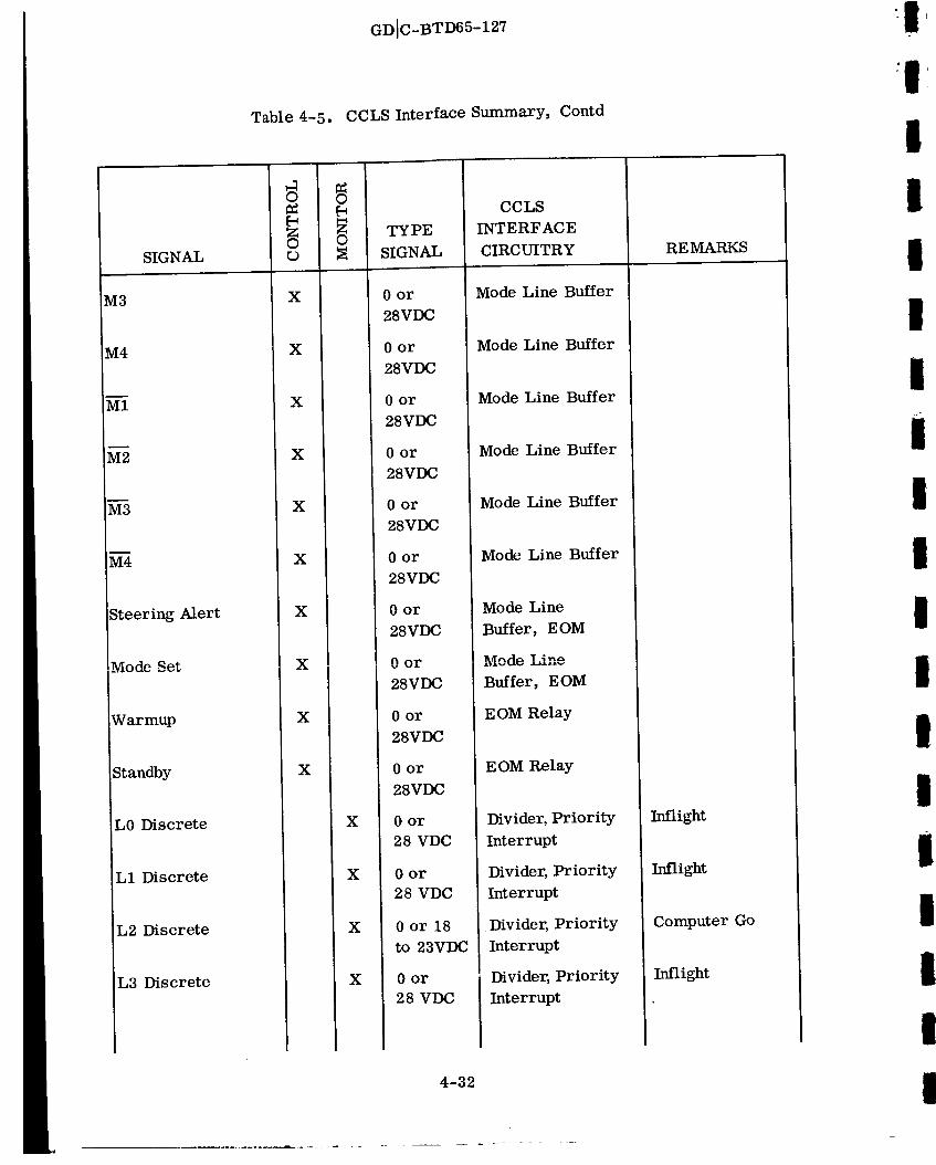
Table 4-5.
i SIGNAL
M3
M4
Steering Alert
!Mode Set
Warmup
Standby
L0 Discrete
Ll Discrete
L2 Discrete
L3 Discrete
v
X
X
X
X
X
X
X
X
X
X
X
X
X
X
GDIC-BTD65-127
CCLS Interface Summary, Contd
TYPE
SIGNAL
0 or
28VDC
0 or
28VDC
0 or
28VDC
0 or
28VDC
0 or
28VDC
0 or
28VDC
0 or
28VDC
0 or
28VDC
0 or
28VDC
0 or
28VDC
0 or
28 VDC
0 or
28 VDC
0 or 18
to 23VDC
0 or
28 VDC
CCLS
INTERFACE
CIRCUITRY
Mode Line Buffer
Mode Line Buffer
Mode Line Buffer
Mode Line Buffer
Mode Line Buffer
Mode Line Buffer
Mode Line
Buffer, EOM
Mode Line
Buffer, EOM
EOM Relay
E OM Relay
Divider, Priority
Interrupt
Divider, Priority
Interrupt
Divider, Priority
Interrupt
Divider, Priority
Interrupt
REMARKS
Inflight
Inflight
Computer Go
Inflight
I
II
II
I
l
i
I
I
I
I
I
I
I
[
4-32

IIIlI
It
II
III
II
IIIlI
Table 4-5.
SIGNAL
L6 Discrete
L7 Discrete
L8 Discrete
L9 Discrete
L10 Discrete
Lll Discrete
L12 Discrete
L13 Discrete
L15 Discrete
L16 Discrete
Computer Telemetry
Fast Heat
Fast Heat Return
U Accelerometer
Temperature
V Accelerometer
Temperature
O
X
O
X
X
X
X
X
X
X
X
X
X
X
X
X
X
GDIC-BTD65-127
CCLS Interface Summary, Contd
TYPE
SIGNAL
0 or
28 VDC
0 or 18
to 23VDC
0 or
28 VDC
0or 18
to 23VDC
0 or
28 VDC
0 or 18
to 23VDC
0or 18
to 23VDC
0 or 18
to 23VDC
0or 18
to 23VDC
0 or
28 VDC
0 or 5VDC
115VAC
60CPS
30VAC
60CPS
0 to 5VDC
0 to 5VDC
CCLS
INTERFACE
CIRCUITRY
Divider, Priority
Interrupt
Divider, Priority
Interrupt
Divider, Priority
Interrupt
Divider, Priority
Interrupt
Divider, Priority
Interrupt
Divider,Priority
Interrupt
Divider, Priority
Interrupt
Divider, Priority
Interrupt
Divider, Priority
Interrupt
Divider,priority
Interrupt
Telemetry Buffer
EOM Relay
Filter Rectifier
Mux A_D
Filter Mux A/D
Filter Mux A/D
REMARKS
Inflight
LOT Time Accept
Inflight
Flight Mode
Accept
Inflight
RL&R Frame
Complete
Mode Complete
RL&R Operation
Complete/Memory
Sum OK
Mode Accept
Inflight
Pulse Rebalance
Signal Conditioner
4-33

Table 4-5.
SIGNAL
W Accelerometer
Temp Readout
U Gyro Temperature
Readout
IV Gyro Temperature
Readout
W Gyro Temperature
Readout
48VDC Monitor
13.5VAC Steering
Excitation _ Phase
13.5VAC SteeringExcitation O Phase
X Steering
Y Steering
Gimbal 1
Resolver
Resolver
Gimbal 1
Resolver
Resolver
Gimbal 3
Resolver
Resolver
Gimbal 3
Resolver
$1
$1 Common
$2
$2 Common
$3
$3 Common
$4
c9 !
GDIC-BTD65-127
CCLS Interface Summary, Contd
X
X
X
X
X
X
X
X
X
X
X
X
X
TYPE
SIGNAL
0 to 5VDC
0 to 5VDC
0 to 5VDC
0 to 5VDC
+48VDC
13.5VAC
400CPS
13.5VAC
400CPS
7.14VAC
400CPS
7.14VAC
400CPS
17VAC
400CPS
17VAC
400CPS
17VAC
400CPS
17VAC
400CPS
CCLS
INTERFACE
CIRCUITRY
Filter Mux A/D
Filter Mux A/D
Filter Mux A/D
Filter Mux A/D
Filter Mux A/D
Filter Rectifier
Mux A/D
Filter Rectifier
Mux A/D and
Counter
Demodulator
Mux A/D
Demodulator
Mux A/D
Demodulator
Mux A/D
Demodulator
Mux A/D
Demodulator
Mux A/D
Demodulator
Mux A/D
REMARKS
Pulse Rebalance
Signal Conditioner
Platform
Electronics
Signal Conditioner
TCA Heater Supply
4-34
1
:1I
i
!
I
I
I
I
I
i
I
I
!
r

I
II
1I
I
III
II
II
l
I
IIi
I
SIGNAL
Resolver $4 Common
Steering Output U
Steering Output V
Steering Output W
Steering Output X
Steering Output Y
Gimbal 1 Servo
Signal
Gimbal 2 Servo
Signal
Gimbal 3 Servo
Signal
Gimbal 4 Servo
Signal
Gimbal 1 Servo
Signal
Gimbal 2 Servo
Signal
Hmbal 3 Servo
sig_
Gimbal 4 Servo
Signal
Gimbal 4 Cage Relay
Table 4-5.
I
X
X
X
X
X
X
X
X
X
X
X
X
X
X
GDIC-BTD65-127
CCLS Interface Summary, Contd
TYPE
SIGNAL
0to 5VDC
Oto 5VDC
0 to 5VDC
0 to 5VDC
0to 5VDC
0 + 10VDC
0 + IOVDC
0 + IOVDC
0 + 10VDC
Oto 5VDC
0to 5VDC
0to 5VDC
0 to 5VDC
0 to 5VDC
CCLS
INTERFACE
CIRCUITRY
Filter Mux A/D
Filter Mux AiD
Filter Mux A/D
Filter Mux A/D
Filter Mux A/D
Filter Mux A/D
& GSI Circuit
Filter Mux A/D
& GSI Circuit
Filter Mux A/D
Filter Mux A/D
& C-SI Circuit
Filter Mux K/D
Filter Mux A/D
Filter Mux A/D
Filter Mux A/D
Filter Mux A/D
REMARKS
Signal Conditioner
Output
Signal Conditioner
Output
Signal Conditioner
Output
Signal Conditioner
Output
Signal Conditioner
Output
Platform
Electronics
Platform
Electronics
Platform
Electronics
Platform
Electronics
Signal Conditioner
Signal Conditioner
Signal Conditioner
Signal Conditioner
Signal Conditioner
4-35

SIGNAL
Gimbal 4 Cage
Relay
Gimbal 1 Align
Gimbal 3 Align
Gimbal 4 Align
Resolver Align
Relay
Gimbal 4 Align
Relay
Align Relay
U Gyro Torque
V Gyro Torque
W Gyro Torque
U Gyro Torque
V Gyro Torque
W Gyro Torque
+22.2VDC Torque
Excitation
-22.2VDC Torque
Excitation
Table 4-5.
GDIC-BTD65-127
CCLS Interface Summary, Contd
!
0
o
X
X
X
X
X
X
X
A
w
X
X
X
X
X
X
X
X
TYPE
SIGNAL
0 or
+12VDC
or Open
-i0 to
+10VDC
-10 to
+IOVDC
-i0 to
+10VDC
0 or
+28VDC
0 or
+28VDC
0 or
+28VDC
0± 22.2
VDC
0+ 22.2
VDC
0± 22.2
VDC
0 to 5VDC
0 to 5VDC
0 to 5VDC
+22.2VDC
-22.2VDC
CCLS
INTERFACE
CIRCUITRY
E OM Relay
D/A Converter
Output
D/A Converter
Output
D/A Converter
Output
EOM Relay
EOM Relay
EOM Relay
Filter Mux A/D
Filter Mux A/D
Filter Mux A/D
Filter Mux A/D
Filter Mux AcID
Filter Mux A/D
Filter Mux A/D
Filter Mux A/D
REMARKS
Pulse Rebalance
Pulse Rebalance
Pulse Rebalance
Signal Conditioner
Signal Conditioner
Signal Conditioner
4-36
I
:IIiI
I
III
III
I
III
III

I
!
I
I
I
I
I
!
i
I
I
I
I
l
l
!
!
Table 4-5.
SIGNAL
Gyro Pattern Field
Supply
3.7V 7.2KC Monitor
Gimbal 1 Demodu-
lator Output
Gimbal 2 Demodu-
lator Output
Gimbal 3 Demodu-
lator Output
Gimbal 4 Demodu-
lator Output
Gimbal 1 Demodu-
lator Output
Gimbal 2 Demodu-
lator Output
Gimbal 3 Demodu-
lator Output
Response Test
Relay
+AV U
- AV U
+ _V V
-&V V
+AV W
-AV w
3.7VDC AV Bias
0
X
GDIC-BTD65--127
CCLS Interface Summary, Contd
0
X
X
X
X
X
X
X
X
X
X
X
X
X
X
X
X
TYPE
SIGNAL
0to
25VDC
3.7V
7.2KC
0 to 5VDC
0 to 5VDC
0 to 5VDC
0 to 5VDC
0 to 5VDC
0 to 5VDC
0 to 5VDC
0 or
+28VDC
0 or 5VDC
0 or 5VDC
0 or 5VDC
0 or 5VDC
0 or 5VDC
0 or 5VDC
3.7VDC
CCLS
INTERFACE
CIRCUITRY
Filter Mux A/D
Filter Mux A/D,
&V Counter BuffeI
Filter Mux A/D
Filter Mux A/D
Filter Mux A/D
Filter Mux A/D
Filter Mux AfD
Filter Mux A/D
Filter Mux A/D
EOM ReLy
AVU Counter
AVU Counter
AVV Counter
AVv Counter
AVW Counter
AVw Counter
Filter Mux A/D
REMARKS
Operational Signal
Conditioner
Operational Signal
Conditioner
Operational Signal
Conditioner
Operational Signal
Conditioner
R&D Signal
Conditioner
R & D Signal
Conditioner
R & D Signal
Conditioner
4-37

Table 4-5.
SIGNAL
100CPS Monitor
U Accelerometer
Demodulator Output
V Accelerometer
Demodulator Output
W Accelerometer
Demodulator Output
Power Control
Power On Indicator
GOAS Hatch Open
Control
"GOAS Hatch Closed
Control
GOAS Hatch Open
Indicator
GOAS Hatch Closed
Indicator
Fairing Hatch OpenControl
Test Mode Control
Test Mode Indicator
Auto MGS Connected
Signal
(J
X
X
X
X
X
X
A
v
X
X
X
X
X
X
X
X
GDIC-BTD65-127
CCLS Interface Summary, Contd
TYPE
SIGNAL
0 to 5VDC
0 to 5VDC
0 to 5VDC
0 or
+28VDC
0 or
+28VDC
0 or
+28VDC
0 or
+28VDC
0 or
+28VDC
0 or
+28VDC
0 or
+28VDC
0 or
+28VDC
0 or
+28VDC
0 or
+28VDC
CCLS
INTERFACE
CIRCUITRY
Filter Mux A/D
AV Counter
Filter Mux A/D
Filter Mux A/D
Filter Mux A/D
EOM Relay
Divider - SKS
EOM Relay
E OM Relay
Divider - SKS
Divider - SKS
EOM Relay
E OM Relay
Divider - SKS
E OM Relay
RE MARKS
116 Accelerom-
eter only
Operational Signal
Conditioner
Operational Signal
Conditioner
Operational SignalConditioner
Optical Alignment
Optical Alignment
4-38
I
:II
III
II
I
III
Ii
II
I
IiI

!
!
!
!
i
!
!
!
Ii
!
!
!
I
!
!
!
!
!
I
Table 4-5.
SIGNAL o
MGS Connected
Indicator
Torque Control
Interlock
Acquisition Signal
X
X
X
Blockhouse Torque
Indicator
GOAS Torque
Indicator
Error Meter Hi
Error Meter Return
-30VDC
X
X
X
X
+30VDC X
Manual Torque
Signal
Optical Torque
X
X
Optical Torquing
Signal Control
X
Manual Torque
Indicator
+Manual Torque
Local Control
X
X
GDIC-BTD65--127
CCLS Interface Summary, Contd
TYPE
SIGNAL
0 or
+28VDC
0 or
+28VDC
0 or
+28VDC
0 or
+28VDC
0 or
+28VDC
_3VDC
-30VDC
+30VDC
-30 or 0,
or +30VDC
0to
_30VDC
0 or
+28 VDC
0 or
+28VDC
0 or
+28VDC
CCLS
INTERFACE
CIRCUITRY
Divider - SKS
EOM Relay
Divider - SKS
Divider - SKS
Divider - SKS
Filter Mux A/D
Relay
Relay
EOM Relay
Filter Mux A/D
EOM Relay
Divider - SKS
EOM Relay
REMARKS
Optical Torquing
Excitation
Optical Torquing
Excitation
Allows Optical
Torquing to be
Monitored (was
DVM Input Control)
4-39

GDIC-BTD65-127
4.5.1 Analog Voltage Measurements. The general circuit configuration of the signal
to be measured is shown in Figure 4-3. Before signal EIN is measured, it must pass
through three resistors, R 1, R2, and R M. R 1 is an isolation resistor located in the
guidance system and used to protect the signal source against possible external ground-
ing. R 2 is used to control the gain of the amplifier located at the input of the multi-
plexer and is selected to attenuate signals that would otherwise exceed the range capa-
bility of the analog-to-digital converter. This resistor will be located in one of the
two CCLS auxiliary electronics cabinets. R M is the resistor used to control the gain
of the amplifier and the input impedance of the multiplexer. R M is located in the
multiplexer and can have 1 of 3 possible values: 1 megohm, 100, 000 ohms, or 10, 000
ohms. The value of RM is selected when the multiplexer is purchased.
The accuracy to which each measurement could be made was calculated in this study.
The following tolerances were taken into consideration:
a. Isolation resistor, R 1, tolerance: A function of the particular airborne signal
source.
b. Gain control resistor, R 2, tolerance: + 0.01 percent or + 0.1 percent {depending
upon the resistor selected).
c. Input resistor, R M, tolerance: + 0.01 percent.
d. Analog-to-digital converter random inaccuracy: + 0. 003 volts.
The accuracy equation is developed in Appendix B. Since the equation is linear, the
worst-case positive and negative errors can be specified as shown in the appendix.
The maximum uncertainty that could result in the measurement of any analog signal is
X + 2Y percent, where X is the signal source tolerance, and Y is the instrumentation
error, both in percent. The number to be used as a basis for determining whether a
particular voltage is within the allowable voltage band will be the nominal signal level,
plus or minus the sum of the instrumentation error and the signal source tolerance.
Defining the allowable band in this manner will ensure that no acceptable voltages are
rejected, and will, in worst case, allow voltages that are at nominal value plus or
minus X + 2Y percent to be accepted.
The signal frequencies of interest are usually below 50 CPS. An RC low-pass filter
with a 3 db point of 50 CPS will normally be used to suppress noise. The input to the
multiplexer will have the configuration shown in Figure 4-4, where:
EIN = Signal voltage
R 1 = Isolation resistor
4-40
II
II
i
I
II
iI
II
IiI
I
III
i I i
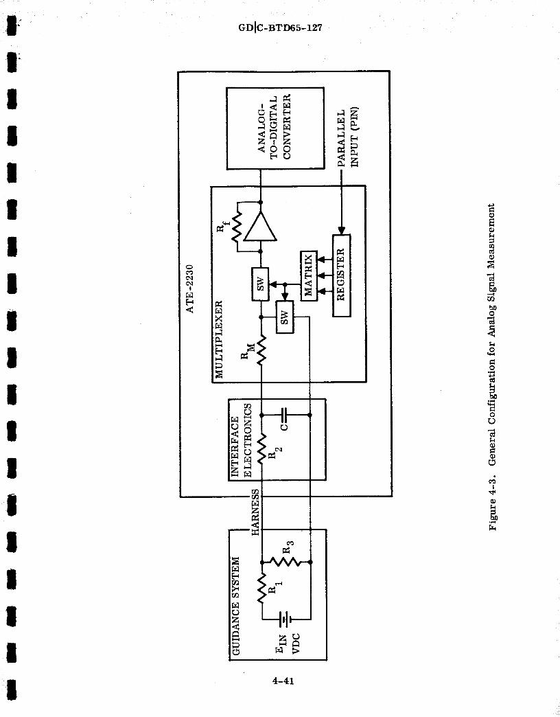
III
I
II
i
li
GDIC-BTD65-127
!
_oz _
I_= _ '>I_ >_
r_
N L-t'I_
4-41
b_0
0
0
0L_
L_
I

GDIC-BTD65-127
R 2 = Gain adjust resistor
R 3 = Attenuation resistor
C --- Filter capacitor
R M = Multiplexer input resistor
f = 3db frequency3db
E M = Voltage drop across multiplexer input resistor
R 1 R 2
--C E M
Figure 4-4. Multiplexer Input Configuration
Resistor R 3 appears in only some of the airborne circuits to be monitored. Whereapplicable the effect of this resistor is included in the calculations {Appendix B) for
evaluation of the circuit accuracy and filter capacitor size. It should be noted that the
capacitance of the long-run landline cable has not been included in the analysis to date.
In addition, analysis of the standing-wave patterns that may cause the filtering to be
ineffective has yet to be accomplished. This thorough analysis, based on Noise Speci-
fication 55-03016 {Reference 3), should be conducted prior to the final design review
of the circuitry.
Appendix B also contains the derivation of EDC, the voltage at the output of the analog-
to-digital converter. This voltage is a function of the tolerances and nominal values
of the circuit resistors and the random conversion inaccuracy.
The grounding philosophy to be employed for the CCLS, shown schematically in
Figure 4-5, can be summarized as:
4-42
-I;I
III
II
I
II
III
Il
III
I

J
I
IlI
I
II
III
III
I
l
II
i
_r_
I
r_
oO
oO
0
N-i
GDIC-BTD65-127
O
L
r_
Z
I
i i'I'A
r_
_r
4-48
II,
O
CO
b_O
O
b_
0
_J
!

GDIC-BTD65-127
a. All power supply grounds shall be referenced to the guidance system.
b. Signal returns from the multiplexer shall be referenced to the guidance system.
Only analog returns of signals that are being measured shall be permitted on this
line. This precaution reduces the current flow in the analog return that might
otherwise cause sizable voltages to develop between the multiplexer and the
guidance system. This voltage buildup might result from the distributed resist-
ance in the analog return.
c. The power supply for the signal measuring equipment shall have its ground
referenced to the guidance system and not to the CCLS chassis. This precaution
prevents ground loops.6
d. All ground return wires shall be sized so the voltage developed across its length,
due to its distributed resistance, will add a negligible error to the signal beingmeasured.
4.5.1.1 Torquing Potentiometer Excitation. The positive and negative excitation
voltages for the airborne computer's torquing potentiometers originate in the combined
voltage regulator module of the coupler. The signal levels are plus and minus 22.2
VDC with a specified tolerance of ± 0.1 percent. Each signal passes through an isola-
tion resistor, R1, of 49,900 ohms +1 percent; an umbilical line; the gain control re-
sistor R2; filter capacitor C; and terminates at the input of the multiplexer.
For system checkout, the measurement accuracy will be + 0.2 percent, or a factor of
two worse than the tolerance on the power supply itself. It will be shown that this
error will not adversely affect the guidance system, since it is small with respect to
the maximum allowable gyro fixed torque drift uncertainty (0.18 deg/hr).
The maximum gyro torque error that will be induced by the measurement inaccuracy
can be found by multiplying the maximum gyro fixed torque drift by the total worst-
case percentage error. The result of the error calculation is 0.015 deg/hr. This is
seen to be small compared to 0.18 deg/hr.
The values used to determine the measurement error, in percent, and the size of the
filter capacitor are in Table 4-6.
Based on the values given in Table 4-6 and the equations of Appendix B, the following
values were obtained:
EDCno m = 4.95 VDC
Error = 0.202%
C = 0.04Df
4-44
I
:1
I
I
I
I
I
I
i
i
r
1
I
I
I
I
I

I
I
GDIC-BTD65-127
Table 4-6. Parameter Values for Torquing Potentiometer
Excitation Measurement
II
II
PARAMETER
MINIMUM NOMINAL MAXIMUM
VALUE VALUE VALUE
R 49,401 f_ 49,9001
R 2 299,970 f/ 300, 000 f_
Rf - 100, 000 G
R M 99,990 G 100, 000 f/
100, 010
I
IIII
I
I
I
l
I
II
4.5.1.2 Gyro Pattern Field Supply. The signal to be measured originates in the
gyro pattern field supply module, located in the coupler. Its purpose is to provide a
constant current to the gyro pattern fields. The signal level is 21.2 VDC nominal and
has a specified tolerance of ± 0.31 percent (equivalent to 21.2 VDC with a constant
current value of 10.6 mllliamps ± 34 microamps). The signal passes through isolator
resistor R 1 (100K f/ ± 1 percent), an umbilical line, a gain control resistor R 2
(250K t_ • 0.01 percent), a filter capacitor C, and terminates at the input of the multi-
plexer.
For system checkout, the measurement accuracy will be ±0.31 percent, or approxi-
mately the same as the tolerance on the power supply. The maximum error of one
percent (X + 2Y) will not adversely affect the guidance system, since one percent of
the maximum gyro drift rate, 0.03 deg/hr, is small with respect to the maximum
allowable gyro drift uncertainty (0.18 deg/hr).
The values used to determine the measurement error, in percent, the size of the filter
capacitor and the nominal analog-to-digital converter output are given in Table 4-7.
Based on the values given in Table 4-7 and the equations of Appendix B, the following
values were obtained-
EDCno m = 4.664 VDC
Error = 0.314%
C = 0.04_f
4-45
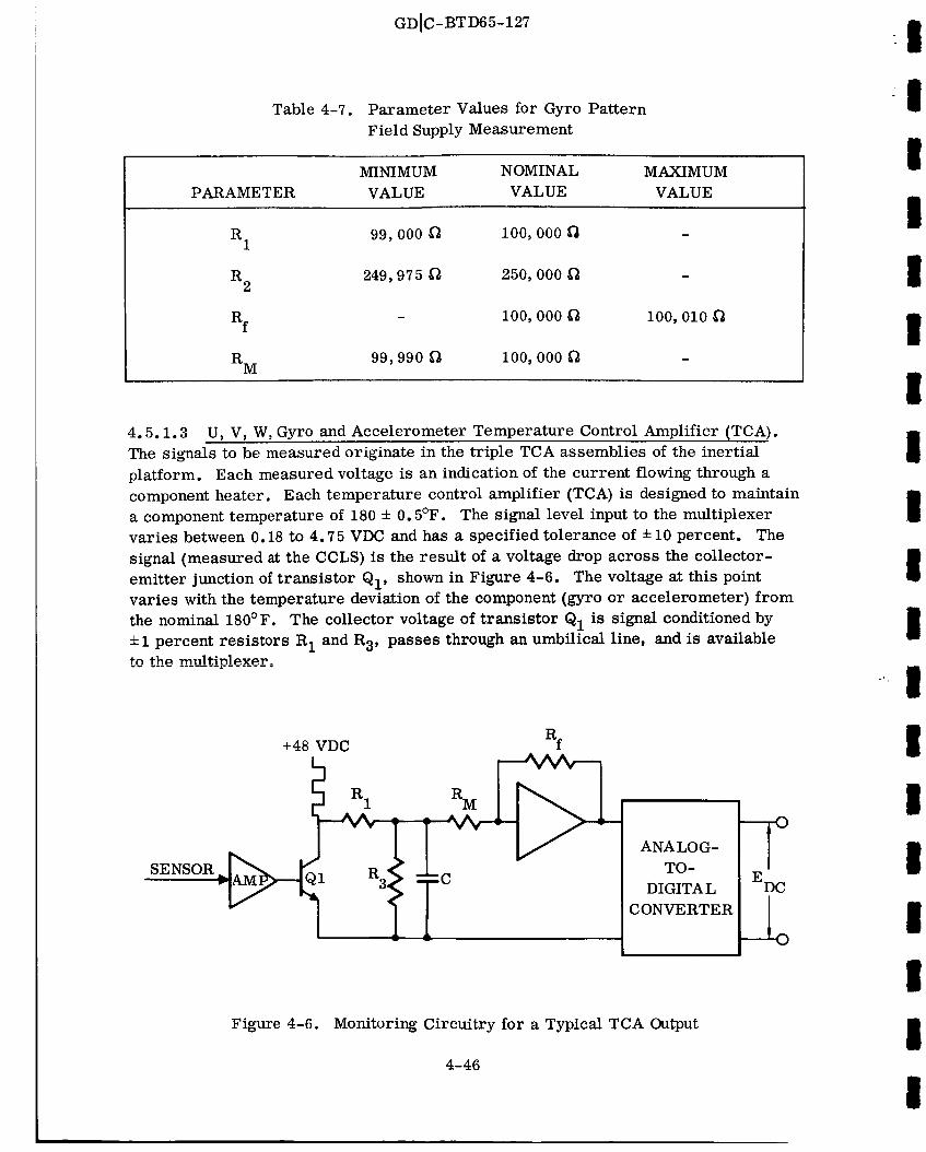
GDIC-BTD65-127
Table 4-7. Parameter Values for Gyro Pattern
Field Supply Measurement
MINIMUM NOMINAL MAXIMUM
I!
IPARAMETER VALUE VALUE VALUE
R 1 99,000 _ 100, 000
R 2 249,975 _ 250, 000
Rf - 100, 000
R M 99,990 _ 100, 000
100, 010
iIl
!4.5.1.3 U, V, W, Gyro and Accelerometer Temperature Control Amplifier (TCA).
The signals to be measured originate in the triple TCA assemblies of the inertial
platform. Each measured voltage is an indication of the current flowing through a
component heater. Each temperature control amplifier (TCA) is designed to maintain
a component temperature of 180 + 0.5°F. The signal level input to the multiplexer
varies between 0.18 to 4.75 VDC and has a specified tolerance of + 10 percent. The
signal (measured at the CCLS) is the result of a voltage drop across the collector-
emitter junction of transistor QI' shown in Figure 4-6. The voltage at this point
varies with the temperature deviation of the component (gyro or accelerometer) from
the nominal 180°F. The collector voltage of transistor Q1 is signal conditioned by
+ 1 percent resistors R 1 and R 3, passes through an umbilical line, and is availabletn fh_ rnultinl_c_r.
SENSOR
+48 VDC
ANALOG-
TO-
DIGITAL
CONVERTER
EDC
_2
Figure 4-6. Monitoring Circuitry for a Typical TCA Output
4-46
I
I
II
"" I
I
I
I
I
I
II

GDIC-BTD65--127
For system checkout, the signal measurement will be approximately six times more
accurate than the tolerance of the signal being measured.
The values used in the calculations are given in Table 4-8.
Table 4-8. Parameter Values for Gyro and Accelerometer Temperature
Control Amplifier Measurements
III
I
PARAMETER
MINIMUM NOMINAL MAXIMUM
VALUE VALUE VALUE
R 1 9,900 G 10, 000
R 3 1, 139 _ 1, 150
RX 1,020 G 1, 030
Rf - 100, 000
R M 99,990 _ 100, 000 G
100, 010
III
Il
I
I
III
Based on the values given in Table 4-8 and the equations of Appendix B, the following
values were obtained:
EDC = 0.180 (for EIN = 1.765 VDC)nom
Error = 1.69 %
C = 3.2Df
4.5.1.4 Temperature Control Amplifier (TCA) Heater Supply. The signal to be
measured originates in the +48 VDC power supply module, located in the coupler.
This signal supplies inertial component TCA heater current. The signal level is +48
VDC nominal and has a specified tolerance of ± 10 percent. The signal passes through
isolation resistor R1, an umbilical line, filter capacitor C, and terminates at the
input of the multiplexer.
For system checkout, the measurement accuracy will be 0.1 percent (100 times more
accurate than the tolerance of the signal being measured).
The values used to determine the measurement error, nominal analog-to-digital con-
verter output voltage, and the size of the filter capacitor are given in Table 4-9.
4-47

GDIC-BTD65-127
Table 4-9. Parameter Values for TCA Heater Supply Measurement
MINIMUM NOMINAL MAXIMUM
IIII
PARAMETER VALUE VALUE VALUE
R 327 _ 3301
Rf - i0, 000
R M 99,990 _ 100, 000
10, 001
IIII
Based on the values given in Table 4-9 and the equations of Appendix B, the following
values were obtained.
EDCno m = 4.784 VDC
Error = 0.1%
C = 9.68Df
4.5.1.5 Accelerometer Modulator Coil Excitation. The signal to be measured
originates in the +35 VDC power supply, located in the coupler, and provides modula-
tion coil excitation to the accelerometer. The signal level is 3.7 volts nominal and
has a specified tolerance of +1 percent.
The signal, as shown in Figure 4-7, is the result of the voltage division between cur-
rent limiting resistor R 1 and resistor combination R L, R C, and R I (line resistance,
torquer coil resistance, and the inductor resistance respectively; the line resistance
was measured using existing GSE). The monitored signal passes through a 10K ohm
isolation resistor, through the umbilical, and is then available to the multiplexer.
For system checkout, the measurement accuracy, as will be developed, is 0.48 per-
cent, whereas the quantity to be measured has a specified tolerance of _1 percent.
The values used to determine the measurement error, the nominal analog-to-digital
converter output voltage, and the size of the filter capacitor are given in Table 4-10.
4-48
II
I
II
I
II
I
III
I

GDIC-BTD65-127
I Rf
I
IEIN _--'_-" _R C _CI
, I IANALOG-
TO-
DIGITAL
CONVERTER
Figure 4-7. Monitoring Circuitry for Accelerometer
Modulator Coil Excitation
Table 4-10. Parameter Values for Accelerometer Modulator
Coil Excitation Measurement
EDC
I
l
Il
Il
I
PARAMETER
MINIMUM NOMINAL MAXIMUM
VALUE VALUE VALUE
R 175 _ 1801
R 2 9,500 _ i0, 000
R L - 3.4 i'i
R - 10.6 f_C
R I - 7.2
Rx 18.466 _ 18.966
Rf - i00, 000
R M 99,990 _ 100,000
100, 010 l_
4-49

GDIC-BTD65-127
Based on the values given in Table 4-10 and the equations of Appendix B, the following
values were obtained:
EDCno m = 3.292 VDC
Error = 0.477%
C = 3.5Df
4.5.1.6 +28 VDC Supply. Prime +28 VDC power is supplied to guidance from a
source external to the system. Its purpose is to provide power to the airborne com-
puter, platform electronics, platform, coupler, and the signal conditioner. The speci-
fied tolerance of the +28 VDC supply is + 10 percent. The signal passes through a 10K
ohm isolation resistor, an umbilical line, and then is available to the multiplexer.
For system checkout the measurement accuracy will be 0.15 percent.
The values used to determine the measurement error, nominal analog-to-digital con-
verter output, and the size of the filter capacitor are given in Table 4-11.
Table 4-11. Parameter Values for +28 VDC Supply Measurement
I
I
I
I
II
II
I
IPARAMETER
MINIMUM NOMINAL MAXIMUM
VALUE VALUE VALUE
1_ 9, ann .f_. nnn_1,1 *,_ v_ 10,
Rf - 10, 000
R M 99,900 _ 100, 000
10,001
I
II
Based on the values given in Table 4-11 and the equations of Appendix B, the following
values were obtained:
EDCno m = 2. 545 VDC
Error = 0.157%
C = 1.1Df
4-50
I
I
I
I
I
I

GDIC-BTD65-127
4.5.1.7 +35 VDC Supply. The signal to be measured originates in the +35VDC power
supply module, located in the coupler, and is the result of the voltage division between
the resistor combination R 1, R 2, and R 3 (see Figure 4-8). The input signal has a
specified tolerance of ±1 percent. The attenuated signal enters the umbilical and is
I available to the multiplexer.
.f
' R I R 2 RM
[
I
ANALOG-
TO-
DIGITAL
CONVERTER
-rEDC
_2I
lIl
Figure 4-8. +35VDC Monitoring Circuit
For system checkout, the monitoring accuracy will be _0.1 percent, which is 10 times
more accurate than the tolerance of the +35 VDC supply.
The values used to determine the measurement error, the nominal analog-to-digital
converter output, and the size of thefilter capacitor are given in Table 4-12.
Table 4-12. Parameter Values for +35 VDC Supply Measurement
MINIMUM NOMINAL MAXIMUM
I
l
Iil
PARAMETER VALUE VALUE VALUE
R 1 950 i'_ I,000 i'l
R 2 17,226 _ 17,400
R 3 2, 248 _ 2,260
R x i,992 _ 2,012
Rf - i00, 000
R M 99,990 _ i00, 000
i00,010 i'i
4-51

GDIC-BTD65-127
Based on the values given in Table 4-12 and the equations of Appendix B, the following
values were obtained:
EDCno m = 3.751 VDC
Error = 0.13%
C = 1.6/_f
4.5.1.8 Gimbals 1, 2, 3, and 4 Servo Motor Signals. The signals to be measured
are the outputs of the gimbal control amplifiers, which are used to drive the gimbal
torque motors to align and stabilize the platform. The signal levels for the four
gimbal torque motor inputs are:
a. Gimbal 1: 0 to 14.5 VDC
b. Gimbal 2: 0 to + 3.3 VDC
c. Gimbal 3: 0 to ± 5.3 VDC
d. Gimbal 4: 0 to + 2.2 VDC
The measured signals have specified tolerances of + 10 percent. Each signal originates
in the power demodulator, enters an isolation resistor (R1), passes through the umbil-ical, and enters the multiplexer (see Figure 4-9).
OUTPUT
POWER ..DEMODULATOR
RE TURN O
Rf
_ANALOG_TO_
= C DIGITAL
CONVERTER
i
fE
DC
_2
Figure 4-9. Monitoring Circuitry for Gimbals 1, 2, 3, and 4
Servo Motor Signals
4-52
i
III
I!II
IiI
II
iI
!!aI

:
III
I
GDIC-BTD65-127
For system checkout, the monitoring accuracy will be 0.18 percent, as compared to a
signal tolerance of ± 10 percent.
The values used to determine the measurement error, the nominal analog-to-digital
converter voltage output, and the size of the filter capacitor are given in Table 4-13.
Table 4-13. Parameter Values for Gimbals 1, 2, 3, and 4
Servo Motor Measurements
PARAMETER
MINIMUM NOMINAL MAXIMUM
VALUE VALUE VALUE
R 1 990 _ 1,000
Rf - 100, 000
R M 99,990 _ 100, 000 I±
100, 010
III
I
IlI
II
II
Based on the values given in Table 4-13 and the equations of Appendix B, the followingvalues were obtained:
EDCno m = 2.177 VDC (forEIN = 2.2 VDC)
Error = 0.183%
CGimbal 1 Signal = 16 Df (f3db = 10 CPS)
CGimbal 2, 3, 4 Signals = 32 Df (f3db = 5 CPS)
4.5.1.9 U, V, W, Gyro Torque Signal. The control field of each gyro is excited
from the wiper of a potentiometer located in the airborne computer. The gyro control
field current is linearly proportional to the rotation of the wiper with respect to the
center tap, which is at signal ground. The signal to be measured is the potential
between the arm and the center tap. The signal level can vary between 0 and ± 22.2
VDC, depending on the arm position. The tolerance of the 22.2V supply is ± 0.1 per-
cent. The signal from the arm of each torque potentiometer, passes through an isola-
tion resistor R 1 (10K_ + 1 percent), an umbilical line, gain control resistor R2,
filter capacitor C, and terminates at the input of the multiplexer (see Figure 4-10).
For system checkout, the measurement accuracy will be + 0.10 percent, which is
approximately the same as the tolerance of the signal being measured.
4-53

GDIC-BTD65-127
EIN
R 1 R 2
i C
Rf
_ ANALOG_TO_
DIGITAL
CONVERTER
Figure 4-10. Monitoring Circuitry for Gyro Torque Signal
Under worst-case conditions, the total inflight error which could result from this
tolerance buildup would be 0.3 percent, which is small compared to the over-all
0.18 deg/hr
uncertainty of 3 deg/hr = 6 percent.
The values used to determine the measurement error, the nominal analog-to-digital
converter voltage output, and the size of the filter capacitor are given in Table 4-14.
Table 4-14. Parameter Values for Gyro Torque
Signal Measurements
I
III
iiI
I
III
PARAMETER
MINIMUM NOMINAL MAXIMUM
VALUE VALUE VALUE
R 1 9,900 _ 10, 000 f_
R 2 149,985 f_ 150, 000 f_
R M 99,990 _ 100, 000 f_
Rf - i00, 000 i_ i00, 010 i'_
I
III
Based on the values given in Table 4-14 and the equations of Appendix B, the followingvalues were obtained:
EDCno m = 8.524 VDC (for EIN = 22.2 VDC)
4-54
II
II

GD[C-BTD65-127
Error = 0.105%
C = 0.74 Df
I
II
iiI
4.5.1.10 Gimbal 4 Cage Signal Conditioner Signal . The gimbal 4 caging relay sig-
nal originates in the platform electronics and indicates the status of the relay by
measuring the potential across the relay coil. The relay is energized prior to launch
by the GSE with a +28 VDC signal with a tolerance of + 10 percent. The 28 VDC is
attenuated by a current limiting resistor, and the voltage level at the relay coil is
approximately 12 VDC. The signal being measured is attenuated through a resistor
divider network and routed through the umbilical to the input of the multiplexer (see
Figure 4-11).
For system checkout, the accuracy will be 0.10 percent, which is 100 times better
than the tolerance of the signal being measured.
5
| R1
EIN
| _
ANALOG-
TO-
DIGITAL
,_ONVERTER
fVDC
_2Figure 4-11. Monitoring Circuitry for Gimbal No. 4 Caging
Relay Signal Conditioner Signal
The values used to determine the measurement error, the analog-to-digital converter
nominal voltage output, and the size of the filter capacitor are given in Table 4-15.
Based on the values given in Table 4-15 and the equations of Appendix B, the following
values were obtained:
EDCno m = 3.912VDC
Error = 0.102%
C -- 1°62 Df
4-55

GDIC-BTD65-127
Table 4-15. Parameter Values for Gimbal 4 Cage Signal
Conditioner Signal Measurement
I
II
PARAMETER
MINIMUM NOMINAL MAXIMUM
VALUE VALUE VALUE
R 1 5,980 _ 6, 040
R 3 2, 980 _ 3,010
R x 1,979 _ 1,998
Rf - 100,000
R M 99,990 _ 100, 000
100, 010
I
II
II
4.5.1.11 Gimbal 1, 2, 3, 4 Servo Signal Conditioner Signals. The voltages to be
measured are the outputs of the phase-sensitive power demodulators located in the
platform electronics module. Each demodulator output is a full wave rectified signal
that is used to drive a DC torque motor in the platform. The tolerance of the 2.49
VDC nominal signal is + 2 percent. The signal is attenuated through a resistor divider
network. The attenuated signal is routed through the umbilical to the input of the
multiplexer (see Figure 4-12).
For system checkout, the monitoring accuracy wiii be 0.12 percent, which is 16 times
better than the tolerance of the signal being measured.
_ R4]
Rf
iic ANALO _ O_Figure 4-12. Monitoring Circuitry for Phase-Sensitive Power Demodulator
Signal Conditioner Signal
4-56
II
II
III
II
lI

III
GDIC-BTD65-127
The values used to determine the measurement error, the nominal analog-to-digital
converter output for EIN = 0VDC, and the size of the filter capacitor are given inTable 4-16.
Table 4-16. Parameter Values for Phase-Sensitive
Power Demodulator Measurements
l
II
I
lI
PARAMETER
MINIMUM NOMINAL MAXIMUM
VALUE VALUE VALUE
R 1 5, 178 _ 5, 230
R 3 1,980 _ 2, 000
R 4 12, 870 _ 13, 000
R X 1, 288 _ 1,301
Rf - 100, 000
R M 99,990 _ 100, 000
100, 010
I
III
I
III
I
Based on the values given in Table 4-16 and the equations of Appendix B, the following
values were obtained:
EDCno m = 2.457 VDC (for EIN = 0 VDC)
Error = 0.122%
C = 24/_f
4.5.1.12 U, V, W Gyro Torque Signal Conditioner Signals. The control field of
each gyro is excited from the arm of the potentiometer located in the computer. The
voltage of the arm with respect to signal ground goes to an amplifier in the signal
conditioner. The amplifier has unity gain, an input impedance of 100K ohms, an out-
put impedance of 2K_, and a 2.5 VDC _1 percent nominal output when the input is
zero volts (potentiometer arm in center position). The amplifier linear tolerance is
+ 5 percent between the voltage range of 0.10 to 5.1 VDC. The signal being measured
passes through an umbilical line to the multiplexer (see Figure 4-13).
For system checkout, the measurement accuracy will be 0.204 percent, which is 5
times smaller than the tolerance of the signal being measured.
4-57

GDIC-BTD65-127
+22.2 VDC
_22._ £
Rf
ANAL2G; TO- _D C
CONVERTER
Figure 4-13. Monitoring Circuitry for U, V, W Gyro Torque
Signal Conditioner Signals
The values used to determine the measurement error, the nominal analog-to-digital
converter voltage output for EIN = 0 VDC, and the size of the filter capacitor are
given in Table 4-17.
Table 4-17. Parameter Values for U, V, W Gyro Torque Signal
Conditioner Signal Measurements
PARAMETER
MINIMUM NOMINAL MAXIMUM
VALUE VALUE VALUE
RIN 99,000 _ 100, 000
R 1 1,900 _ 2,000
Rf - 100, 000
R M 99,990 _ 100, 000
EIN - 2.5 VDC
101,000
100, 010
I
I
III
III
I
III
I
II
I
4-58
III

.
I
III
II
Il
II
II
II
III
I
GDIC-BTD65-127
Based on the values given in Table 4-17 and the equations of Appendix B, the followingvalues were obtained:
EDCno m = 2.450 VDC {for EIN = 0 VDC)
Error = 0.204%
C = 22Df
4.5.1.13 Signal Conditioner U, V, W Signals. The signals to be monitored are
the steering potentiometers outputs that originate in the guidance computer and go to
the gimbal position resolvers. The steering signal voltage and phase are functions of
the potentiometer wiper arm location. When the arm is in mid-position, its potential
with respect to signal ground is zero. Once the arm moves its potential will vary
between 0 and 13.5 VAC, depending on its new position. The phase angle will also
depend on the arm position. When the arm is on one side of midpoint, the voltage will
be in-phase with respect to the vehicle phase-A reference; when the wiper is on the
opposite side of the midpoint, the voltage will be 180 degrees out of phase. The signal
from the arm goes to an amplifier located in the signal conditioner module. When the
arm is in mid-position {zero volts), the output of the amplifier will have a nominal
value of +2.5 VDC. The amplifier output will deviate from the quiescent point with a
gain value of 0.178 VDC/VttMS + 5 percent. The phase of the signal will determine
whether the signal will add or subtract to the quiescent level. The amplifier's
linearity tolerance is • 5 percent in the range of 0 to 13.5 VAC input, and its output
impedance is 2K_ + 5 percent.
The voltage being measured is the amplifier output signal, which is routed through the
umbilical to the input of the multiplexer (see Figure 4-14). Resistor R 3 representsthe telemetry load impedance.
For system checkout, the measurement accuracy is 0.244 percent, which is 20 times
smaller than the tolerance of the signal being measured.
The values used to determine the measurement error, the nominal analog-to-digital
converter output voltage for EIN = 0 VAC, and the size of the filter capacitor are
given in Table 4-18.
4-59

GDIC-BTD65-127 i
t
IOOKQ + 0.01%
i 'ANALOG-TO-
_' Y "_ _o%%_ I
II
Figure 4-14. Monitoring Circuitry for Signal Conditioner
U, V, W Steering Signals
Table 4-18. Parameter Values for Steering Input Measurements
PARAMETER
MINIMUM NOMINAL MAXIMUM
VALUE VALUE VALUE
R.
---1
= R !, 900 ,.Q 2, 000-OUT
R 3 495, 000 _ 500,000
R x 1,893 _ 1,992
Rf - 100, 000
R M 99,990 _ 100, 000
100, 010
II
IIII
III
Based on the values given in Table 4-18 and the equations of Appendix B, the following
values were obtained:
EDCno m = 2.450 VDC
Error = 0.244%
C = 22Df
(for EIN = 0 VAC)
4-60
it
III

m •
GD[C-BTD65-127
_
III
III
m
4.5.1.14 Signal Conditioner X_ Y Steering. The voltages to be monitored are output
signals from the gimbal position resolvers located in the platform. Each resolver sig-
nal goes to an amplifier located in the signal conditioner for monitoring purposes.
The output of the amplifier will have a nominal value of 2.5 VDC when the input signal
is 0 VAC, and will deviate from the quiescent point with a gain value of 0.314 VDC/
VRMS ± 5 percent. The phase of the signal will determine whether the signal will add
to or subtract from the quiescent level. The amplifier linearity tolerance is 55 per-
cent in the range of 0 to 13.5 VAC input.
The voltage being measured is the amplifier output signal, which is routed through
the umbilical to the input of the multiplexer (see Figure 4-15). Resistor R 3 repre-sents the telemetry load impedance. The signal conditioner amplifier has a 2K_
output impedance.
m %
!
ANALOG-TO-
DIGITAL
CONVERTER
IIIe
II
Figure 4-15. Monitoring Circuitry for Signal Conditioner
X, Y Steering Signals
For system checkout, the measurement accuracy will be 0.244_, which is 20 times
better than the tolerance of the signal being measured.
The values used to determine the measurement error, the nominal analog-to-digital
converter output for EIN = 0 VAC, and the size of the filter capacitor are given inTable 4-19.
4-61

Table 4-19.
GDIC-BTD65-127
Parameter Values for Signal Conditioner X, Y
Steering Signal Measurements
PARAMETER
MINIMUM NOMINAL MAXIMUM
VALUE VALUE VALUE
R 1 = ROU T 1,900 _ 2, 000
R 495, 000 _ 500, 0003
R x 1,893 _ 1,992
Rf - 100, 000
R M 99,990 _ 100, 000
100, 010
Based on the values given in Table 4-19 and the equations of Appendix B, the following
values were obtained:
EDCno m = 2.45 VDC (for EIN = 0 VAC)
Error = 0. 244%
C = 8.15 Df
4. = " I= Signal o^_+_ .... o,..,..i•_v,,_ ......._......i, 2, 3, 4 Demodulator Oatputs. n-h_ ._o_.1_
to be measured are the outputs of the gimbal control amplifier demodulators located
in the platform electronics. The input signal to each demodulator amplifier is a
7.2K CPS-gyro output signal received from the inertial platform. The gyro signal is
converted to DC by a full-wave double-ring diode demodulator. The demodulator out-
put is routed to the input of an amplifier located in the signal conditioner module.
The signal conditioner amplifier has unity gain and a linear tolerance of + 5 percent in
the voltage range of 0.10 to 5.1 VDC.
The voltage being measured is the signal conditioner amplifier output signal, which
passes through the umbilical to the input of the multiplexer (see Figure 4-16).
For system checkout, the measurement accuracy will be 0.16 percent, which is 6.1
times better than the 1 percent tolerance of the signal being measured.
4-62

[: GD[C-BTD65-127
i:
I
I "M
I
Figure 4-16. Monitoring Circuitry for Signal Conditioner
Gimbal 1, 2, 3, 4 Demodulator Outputs
The values used to determine the measurement error, the nominal analog-to-digital
converter output for EIN = 0 VDC, and the size of the filter capacitor are given inTable 4-20.
Table 4-20. Parameter Values for Signal Conditioner
Demodulator Output Measurements
PARAMETER
MINIMUM NOMINAL MAXIMUM
VALUE VALUE VALUE
R 1 = ROU T 990 f/ 1,000 f/
Rf - 100, 000
R M 99,990 _ 100, 000 f/
100, 010
Based on the values given in Table 4-20 and the equations of Appendix B, the following
values were obtained:
EDCno m = 2.474 VDC
Error = 0.16%
C = 7.15 _f
(for EIN = 0 VDC)
4-63

GDIC-BTD65-127
4.5.2 AC Signal Measurement. Three types of monitoring circuits will be used by
the CCLS to monitor guidance system and prime power AC signals that interface with
the CCLS:
a. Half-wave rectifiers for measuring system voltages.
b. Full-wave, phase-sensitive demodulators for measuring in-phase or out-of-phase
voltage from the platform resolver outputs.
c. Schmitt-trigger power-fail circuits for detecting failure of input 60- or 400-
cycle power.
The design concepts for these circuits as well as the signals to be monitored are dis-
cussed in the following subsections.
4.5.2.1 Spin Motor Excitation. The signals to be monitored are the 26 VAC +2%,
400 CPS (Phases A and C) signals used to drive the gyro spin motors. The signals
source is the secondary of the spin motor excitation transformer located in the coup-
ler. The signals pass through isolation resistors (1K_+ 2%) enter the umbilical
lines, and go to rectifier-filter networks. The outputs from the rectifier-filters are
terminated at the input of the multiplexer.
4.5.2.2 100 CPS Oscillator Output. The signal to be measured is the output from
the 100 CPS oscillator, located in the platform electronics. (The 100 CPS signal pro-
vides dither excitation for the inertial platform accelerometers.) The signal level is
9 VAC and has a tolerance of +10%. It passes through a 10K_ isolation resistor, enters
the umbilical lines, and goes to a rectifier. The output of the rectifier is connected
to the multiplexer.
4.5.2.3 115 VAC, 400 CPS Prime Power. The signals to be measured are the
115 VAC, 400 CPS prime power signals from the vehicle inverter or the Behlman
Invertron located in the CCLS (for a backup guidnace system test). The 400 CPS
voltage is used to supply power to the Guidance System. The signal levels are 115
VAC nominal and have specified tolerances of +1.75%. The signals enter the CCLS
rectifier circuitry and are sent to the multiplexer after filtering.
4.5.2.4 Steering Potentiometer Excitation. The signals to be monitored are the
excitation voltages for the three 1000-ohm center-tapped potentiometers located in
the airborne computer. The signal from each potentiometer is 27 VAC ±1%. The
signals orginate in the coupler, pass through isolation resistors (10K_ + 2%) enter
the umbilical lines, and go to rectifier and filter networks. The outputs then go to
the multiplexer.
4.5.2.5 Fast Heat Return. The signal to be measured is the return signal from the
gyro and accelerometer heater windings located in the platform unit. A 30 VAC sig-
nal is obtained by routing the fast heat return through a voltage-dropping power
4-64
:1
!I
IIII
II
III
II
II
II

l
II
II
II
IlI
I
III
I
II
i
GDIC-BTD65-127
resistor before returning it to ground. The signal passes from the platform down the
umbilical and landline into the power resistor. The voltage at the hot side of the
resistor is routed to a rectifier and filter and then to the multiplexer.
During system checkout the signal will be measured to a tolerance of 1.8%.
4.5.2.6 Gyro Signal Generator Excitation. The signal to be measured is the excita-
tion for the gyros and gyro demodulators. The signal level is 3.7 VAC and has a
specified tolerance of +0.5 volts. The signal originates in the harmonic filter module
located in the coupler. The sampled signal passes through an isolation resistor
{10K_ + 5%), through the umbilical to a rectifier and filter, and then to the input of
the multiplexer.
4.5.2.7 Resolver Outputs. The signals to be measured are the six resolver output
signals: the X and Y steering, Gimbal 1 {Resolver S1 and $2), and Gimbal 3 (Resolver
$3 and $4) signals. The signals are used to transform the inertial-space referenced
steering signals to pitch (X) and yaw (Y) missile coordinates and to provide a reference
for coarse alignment. The resolvers are excited with a 400 CPS input that comes from
the Centaur or Atlas 400 CPS supply.
When the resolvers are used to perform the coarse alignment function, the six outputs
are routed through umbilical lines to phase-sensitive demodulator circuits. The
demodulators will output full wave rectified signals that have DC values equivalent to
the RMS values of the AC inputs. The polarity of each full-wave signal will depend on
the phase of the steering signal with respect to a reference signal (in phase -- positive,
out of phase -- negative). The full-wave rectified signals will be filtered and then
sampled by the multiplexer. When in the coarse alignment configuration, the X and Y
resolver outputs will vary between 0 and 6.3 VAC, whereas the Gimbal 1 and 3 signals
will vary between 0 and 17 VAC. The Gimbal 1 and 3 interface circuitry will be identi-
cal to that of the X and Y steering signals except for the inclusion of an isolation ampli-
fier that will buffer the X and Y signals o The isolation amplifier will be used to make
the resolver output load purely resistive, to prevent signal phase shift.
For the filters, the DC input impedance, including the multiplexer impedance, will
be 100K ohms, the frequency cutoff point will be 40 CPS (selected from test data and
based on servo control considerations}, and the frequency rolloff rate will be 12db/octave.
When the resolver chain is in the steering configuration, the Gimbal 1 and 3 monitoring
lines will be open circuited within the guidance system. The X and Y signals will be
routed both to the autopilot for use in steering the Centaur vehicle and to the CCLS
for monitoring. The signals will, in this case, vary between 0 and 7.13 VAC, 400
CPS, and will be monitored by the phase-sensitive demodulators that were used in
the coarse alignment configuration.
4-65

GD[C-BTD65-127
4.5.2.8 Guidance System Prime-Power-Fail Detectors. The prime-power (115
VAC, 400 CPS, 3¢) fail detectors will sense the voltage levels of the Behlman Invertron
output or the missile inverter, when monitoring a backup or vehicle-installed guidance
system respectively. The detector circuit will detect voltages dropping below 115
V-(15% of 115 V). (Prime power worst-case condition is -3%.) Voltages below this
level will trigger a pulse to a CCLS system interrupt, assigned to this particular mal-
function, setting it to a waiting status. The interrupt will then be processed according
to its priority.
Figure 4-17 is the detector circuit, and Figure 4-18 is the input waveform to the
Schmitt trigger of the detector. The Schmitt trigger will be calibrated to change state
whenever the signal being sensed drops below 0.5 E 0 (max) - (15% of E 0 (max)), Point B
of Figure 4-18. The output of the Schmitt trigger will be inverted with an inverting
amplifier and will go to the one-shot (monostable multivibrator). A change in state of
the Schmitt trigger will cause the one-shot to send an eight-volt pulse to the appro-
priate CCLS interrupt.
As a result of Schmitt-trigger characteristics, E 0(max) must be 10 volts. The imped-
ance of the voltage divider network (see Figure 4-17) used to reduce El(max) to E0(max)will be 16.2K ohms; this value was selected to keep the effects of noise inputs to a
minimum without discipating an inordinate amount of power. With E 1 (max) calculated as:
El(max) = EI(RMS) _f2-= 162 VAC 5 (4-1)
where
E = 115 VAC (nominal) (4-2)! (RMS)
and the impedance of the Schmitt trigger being 10K ohms, the network component values
are calculated as:
R = 15.2K_1
R = 1.1Kt22
A capacitor will be connected across the input to the Schmitt trigger to filter out high
frequency noise. The capacitor value is determined by selecting an RC decay rate
greater than the descending rate of the AC signal. In order to make the decay rate
greater than the descending rate of the AC signal, the slope of the RC decay curve at
the point corresponding to point A of Figure 4-18 (the maximum slope of E0) must be
equal to or greater than the slope of the AC signal at point A.
The exponential expression for the RC decay f(e) is
-t/RTC
f(e) = 0.5 E 0 (max) _ (validfor t = 0 at point A).(4-3)
4-66
-I
II
III
II
III
II
II
IIII

I
!lI
lI
lI
III
II
Il
lII
I
GDIC-BTD65-127
Z
0
I
Z0
i
,<
.--- r_° -...
.-.- r__ -.--.
L) Z
4-67
=o
0
!
!
Ill
r_
N
I

0 0
GD]C-BTD65-127
I
Ii Ii Ii Iii
_ I I
ilII
I
II
liil
4-68
hi)
o
0
0
;>
I
_D
°,=_
I,
I
IIII
I,I
II
II
II
II
III
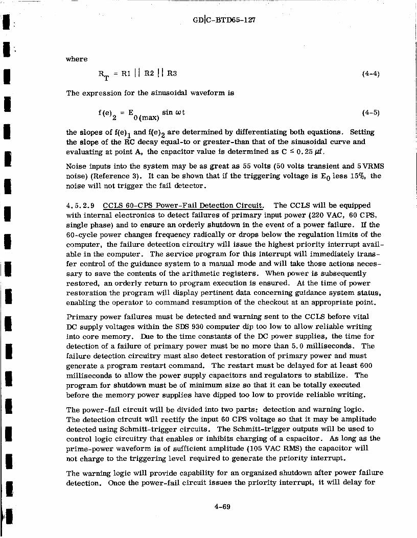
I :
I
IiI
iI
ii
ii
II
Ig
!
I
GDIC-BTD65-127
where
= R1 IJ R2 ]l
The expression for the sinusoidal waveform is
(4-4)
f(e)2 = E0(max) sin _)t (4-5)
the slopes of f(e)l and f(e)2are determined by differentiatingboth equations. Setting
the slope of the RC decay equal-to or greater-than thatof the sinusoidal curve and
evaluating at point A, the capacitor value is determined as C _ 0.25 _Lf.
Noise inputs into the system may be as great as 55 volts (50 volts transient and 5VRMS
noise) (Reference 3). Itcan be shown that ffthe triggering voltage is E 0 less 15%, the
noise will not trigger the faildetector.
4.5.2.9 CCLS 60-CPS Power-Fail Detection Circuit. The CCLS will be equipped
with internal electronics to detect failures of primary input power (220 VAC, 60 CPS,
single phase) and to ensure an orderly shutdown in the event of a power failure. If the
60-cycle power changes frequency radically or drops below the regulation limits of the
computer, the failure detection circuitry will issue the highest priority interrupt avail-
able in the computer. The service program for this interrupt will immediately trans-
fer control of the guidance system to a manual mode and will take those actions neces-
sary to save the contents of the arithmetic registers. When power is subsequently
restored, an orderly return to program execution is ensured. At the time of power
restoration the program will display pertinent data concerning guidance system status,
enabling the operator to command resumption of the checkout at an appropriate point.
Primary power failures must be detected and warning sent to the CCLS before vital
DC supply voltages within the SDS 930 computer dip too low to allow reliable writing
into core memory. Due to the time constants of the DC power supplies, the time for
detection of a failure of primary power must be no more than 5.0 milliseconds. The
failure detection circuitry must also detect restoration of primary power and must
generate a program restart command. The restart must be delayed for at least 600
milliseconds to allow the power supply capacitors and regulators to stabilize. The
program for shutdown must be of minimum size so that it can be totally executed
before the memory power supplies have dipped too low to provide reliable writing.
The power-fail circuit will be divided into two parts: detection and warning logic.
The detection circuit will rectify the input 60 CPS voltage so that it may be amplitude
detected using Schmitt-trigger circuits. The Schmitt-trigger outputs will be used to
control logic circuitry that enables or inhibits charging of a capacitor. As long as the
prime-power waveform is of stffficient amplitude (105 VAC RMS) the capacitor will
not charge to the triggering level required to generate the priority interrupt.
The warning logic will provide capability for an organized shutdown after power failure
detection. Once the power-fail circuit issues the priority interrupt, it will delay for
4-69

GDIC-BTD65-127
250 microseconds to allow the interrupt service routine to be executed, and then it
will automatically disable the core memory current supplies. If the computer was in
the process of computation, shift, or memory cycle when the interrupt occured, the
interrupt will be delayed until such an operation is complete. Thus loss of any infor-
mation will be prevented.
A cycle description of the detection portion of the power-fail circuit best explains its
operation. The timing chart of wave forms in Figure 4-19 shows the signals that
are essential to the power-fail detection. At time T 1 the input voltage waveform pas-
ses through level V1 with a negative slope. Logic within the detection circuit will,
at this point, enable charging of a capacitor toward V A. If the power has not failed,
the waveform subsequently begins increasing amplitude. At time T 2 the detection
circuitry recognizes a Vl-level crossover. Logic using V1 and V 2 then causes the
capacitor to stop charging and hold at this point while the input proceeds toward V2.
The detection circuit will recognize a leveloV 2 crossover at time T 3, and will immed-
iately cause the capacitor to discharge. At time T4 the input waveform will have
passed its peak value and will be again decreasing in amplitude. The voltage sensors
are enabled at this time. By time T 5 the cycle is complete and all conditions return
to the T 1 state.
INPUT
V1 FALSE
TRUE
FALSE
TRUE
V 2
FALSE
TRUE
V 2
FALSE
CAPACITOR
VOLTAGE
Figure 4-19. Power-Fail-Circuit Timing Diagram
4-70
I
I!I
iII
I!
iI!
I!
!
I!I

I-
I
I
I
I
!
I
I
!
I
I
I
I
I
I
I
GD[C-BTD65-127
In addition to the logic already discussed, capability is provided to trigger the voltage
sensor directly and instantaneously, so that the absence of an input voltage will cause
an interrupt to be generated. The logic that accomplishes this function bypasses the
capacitor, and thus the warning is not delayed. If the power should fail:
ao
b.
ct
Between times T 2 and T 3, the capacitor will charge to VA, which triggers the
power-fail interrupt.
During the peak, between times T 3 and T 4, the bypass logic triggers warningdirectly.
Between times T 4 and the next T1, 1 to 5 milliseconds will elapse before the
capacitor voltage is detected as having passed V A. This 5 milliseconds is the
worst-case delay between failure and interrupt.
After power failure detection and computer shutdown, the computer will wait for power
restoration. When power returns, recovery does not take place immediately. A fixed
delay in the logic will start a 600-millisecond wait for all computer power supplies to
stabilize so that memory currents will be fully available. After 600 milliseconds, the
core memory supplies are enabled, and the recovery will be initiated by an interrupt
(from the power-fall circuit) that calls the restart program.
4.5.3 Digital Signal Processing. Five separate design tasks will be undertaken byGD/C in order to process digital interface signals. These include design of counters
and buffers to monitor, format, and input (to the ground computer memory) delta-V
counts and AC signal frequencies, countdown time, Greenwich Mean Time, and air-
borne computer telemetry digital data. An output buffer to hold and output mode-
control, steering-alert, and mode-set data for the airborne computer will also be
designed. The preliminary design concepts for each of these units are discussed in
the following subsections.
4.5.3.1 Counters. Three 24-bit binary counters will be used to count changes of
state of three sets of delta-V signals. Capability will also be included (in 1 of the 3
counters) to check the frequency of 400 CPS, 7.2 KCPS, and 100 CPS signals. The
computer program will issue commands (EOM's) that control counter reset, start and
stop, selection of the input waveform to be counted, and the limit-cycle check value.
Outputs to be accessed by the computer include the algebraic sum of the delta-V counts,
the frequency (in the case of a single input), an indication of missing bits, and indica-
tions of excess bits and excessive limit cycles. An input/output block diagram of a
typical counter is shown in Figure 4-20.
Separate EOM's will be used to select the limit cycle that the delta-V pulse trains will
be compared to. Capability will be provided to select 2-2, 3-3, 4-4, or 5-5 limit
cycles. If the delta-V pulse train exceeds the selected limit cycle, a monostable will
be energized to supply an interrupt to the computer.
4-71

GDIC-BTD65-127
7.2 KCPS
400 CPS
i00 CPS
+DE LTA V
-DE LTA V
START
STOP
RESET
INPUT SE LECTION
SET LIMIT CYCLE
.======_
..=====_==-==._.========_
.========_
=====-=_
.========_
..-====_
COUNTER
DELTA-V ALGEBRAIC SUM
FREQUENCY OF SINGLE SIGNAL
$- EXCESS LIMIT CYCLE INTERRUPT
MISSING BIT INTERRUPT
EXCESS BIT INTERRUPT
EXCESS LIMIT CYCLE SKS
MISSING BIT SKS
EXCESS BIT SKS
Figure 4-20. Counter Input/Output Block Diagram
The inputs to the counter that is designed to check frequency as well as delta-V sig-
nals will consist of:
a. 100 CPS dither supply
b. 7.2 KCPS gyro signal generator excitation
c. 400 CPS guidance prime power
• d. 400 CPS steering excitation
The 7.2 KCPS signal will be used as a synchronization signal for counting of delta-V
pulses. A DC amplifier, which is used for input sighal isolation, will drive a divider
to generate a 3.6 KCPS square wave. This square wave will operate into a monostable
that will be adjusted to allow for the centering of the clock pulse about the nominal
switching times, as shown in the delta-V counter-logic and timing diagram of Figure
4-21.
The mono B output pulse occuring at 3.6 KCPS will define the expected times for delta-
V pulses. Changes of state on the delta-V lines that occur during the clock pulse will
be counted by a reversible binary counter.
4-72
II
IIII
II
II
II
II
II
III

I
I
!I
II
iI
II
II
II
II
!I
I
GD[C-BTD65-127
Any pulses that occur on the delta-V input lines at times other than when mono B is
high will be considered noise pulses and will be rejected by the counters.
Figure 4-22 is a block diagram of a typical delta-V counter. The delta-V signals
will be amplified and then detected by Schmitt triggers. One of the four monostables
at the inputs will provide a pulse output whenever a change of state occurs on either
the plus or minus delta-V input line. This pulse will trigger the up-down control
flip-flop to select the proper gate (up or down) for input to the counter. The pulse
also will trigger a monostable (delay) whose trailing edge will furnish the signal
to be cmmted.
7.2 KCPS
3.6 KCPS
MONO A
MONO B
(C K)
Figure 4-21. Delta-V Counter Synchronization Logic and Timing
4-73

OO
GDIC-BTD65-127 I
_!_0
I I
I
_ I
J I
_0 _
o _
o
_z
+ I
0
o
0
o
I
.q
o,1I
¢)
0_"1
i
I
III
Ii
II
II
I4-74

III
II
III
II
|
III
II
I
II
GD[C-BTD65-127
A missing bit is defined as the occurrence of a clock pulse, CK, with no change of
state on either input delta-V line. A missing-bit indication that occurs in any of the
three counters will cause a priority interrupt signal to be issued to the computer.
The interrupt service routine will then SKS each counter to determine which one
sensed the missing bit. The logic block diagram for this portion of each counter is
shown in Figure 4-23.
MONITOR
POINT A C
MONITOR
POINT B 0
SKS
COUNTER 1
C K EOM
[IIiIL_
IDENTICAL CIRCUIT
FOR COUNTER 2
IDENTICAL CIRCUIT
FOR COUNTER 3
SKS
J COUNTER 2
RESET SKS
EOM COUNTER 3
RESET
EOM
TOPRIORITY
INTERRUPT
I
Figure 4-23. Missing-Bit Monitoring Logic
An excess bit is defined as a simultaneous change of state on both delta-V input lines
to the counter at a time when a single change is expected (a clock time, CK). Simul-
taneous changes of state on both input lines at nonclock times (CK) will be rejected
as noise pulses. The excess bit monitoring circuits will furnish a single priority
interrupt to the computer. The interrupt service routine will SKS each counter to
determine which one sensed the excess bit. The logic block diagram for this portion
of each counter is shown in Figure 4-24.
4-75

GDIC-BTD65-127
MONITOR POINT A __
_o_,_o__oi_;:x=:12/____@RESET EOM SKS
COUNTER
[IDENTICAL
CIRCUIT FOR
I COUNTER 2
L
RESET EOM SKS
COUNTER
I CIRCUIT FOR F]_ _-
] COUNTER 3
i
RESET EOM
SKS
COUNTER 1
T
MONO P_RIoTROIT Y
31 INTERRUPT
Figure 4-24. Excess-Bit Monitoring Logic
Each delta-V counter will contain an excess limit cycle monitor to detect pulse trains
whose polarity does not change often enough. The program will be capable of com-
manding 3-3, 4-4, or 5-5 limit cycles as the no-go criterion. Two three-stage
counters will be used to separately count the plus and minus delta-V pulse. Each
plus pulse will reset the minus delta-V three-stage counter, and each minus pulse
will reset the plus counter. The contents of both counters will be continuously com-
pared with the preset no-go count. If equality between one of the counters and the
preset count is detected, a priority interrupt will occur. The service routine for this
interrupt will SKS each counter to determine which pulse train exhibited an excessive
limit cycle. The logic block diagram for this portion of each counter is shown in
Figure 4-25.
4.5.3.2 Parallel Mode Line Output Buffer. A five-bit holding register that can be
commanded by a word that is output in parallel (via an EOM-POT instruction sequence)
from the ground computer will be provided. This buffer will hold signals that are to
be_ input to the airborne computer as mode-control signals (M 0 through M4, M 1 throughM4), steering alert, and mode set. An input/output block diagram of the mode line
buffer is shown in Figure 4-26.
4-76
:1I
III.
I!i
II
|
I,I!liI
I
II

IIIiiIII
IIlII| _
| _°
II
II
©o_m
GDIC-BTD65-127
T
m
_oo t _ _
m
o
_zoo
0
o
1!__irA-7
_o
4-77
F-'
II II II II I
z zI I o
o I I o
z z
I II II II II IJ L
o
O
O
°_
I

GDIC-BTD65-127
FIVE BIT
PARA L LE L
WORD FROM
GROU N D
COMPUTER
STEERING ALERT EOM
MODE SET EOM
RESET STEERING ALERT
AND MODE SET EOM
HOLDING
REGISTER
AND BUFFER
M 0
Mi
._ M2
M3 MODE
M CONTROL4
_ UNESi
2
3
4
STEERING ALERT
MODE SET
Figure 4-26. Input/Output of Mode Line Buffer
A standard parallel-output (POT) word from the ground computer, which uses only
5 of the 24 available bits, will be employed to input mode-control line data to the
holding register and buffer. Individual EOM's will be used to control the steering
alert and mode set lines via the buffering circuits provided by the mode line buffer.
Eleven buffered outputs with levels of 0 and +28 volts at 2 milliamps will be output
from +_e buffer. Source impedance is less than 2000 ohms.
The mode-set and steering-alert outputs are buffered outputs of RS flip-flops as shown
in Figure 4-27. These flip-flops are set individually and reset as a pair by computer
EOM commands. All outputs are sent to the off state when the program is initialized
by the computer start command. The nine parallel mode-control outputs are set by a
standard, two-instruction program consisting of an EOM instruction followed by a
POT instruction. The EOM sends a SYS pulse with the contents of the C register to
decoding gates. When the applicable address is decoded, the enabling flip-flop is
set, and it, in turn, selects the parallel register as the device to accept the upcoming
POT instruction. The POT instruction then sends a POT2 pulse that strobes the data
in the C register into the holding flip-flops. These flip-flops are wired in the "delay"
or "repeater" configuration. Following the POT2 strobe the POT1 pulse goes low
and resets theenabling flip-flop. The false side of the enabling flip-flop provides a
ready signal, R T, from the external device during the period the device is selected.
All outputs are buffered by GD/C built complementary switches with output of +28
VDC and 0 VDC.
4-78
:I
III
Ii
II
IIIIII
II
III

I
III
!
!Ii
IIIi
iI
II
z
l
© 0 ©
r_ _ m
r.r.t
GDIC-BTD65-127
0 0
[-.,o [.-,0 Z r_ 0
4-79
o
O
o
I
O
o
I
o

GDIC-13TD65-127
4.5.3.3 Countdown Time Decoder. A logic network that decodes the information on
36 parallel lines to provide the CCLS with an indication of countdown time will be
provided. This decoder will accept an equivalent of 5 decades of 7-bit data (total of
35 lines) plus sign. It will decode this input, and it will output 5 decades of 4-bit
BCD (binary coded decimal} data plus a sign bit into the CCLS. An input/output block
diagram of the countdown time decoder is shown in Figure 4-28.
5 DECADES
OF 7-BIT 1I
BCD DATA 1II
I
I SIGN BIT
DE CO DE R
v
CHANGE OF DATA
INTERRUPT
5 DECADES OF4-BIT
BCD DATA
1 SIGN BIT (INVERTED)
Figure 4-28. Countdown Time Decoder Input/Output Block Diagram
The inputs consist of 36 lines of parallel digital data. The logic levels are +28 VDC
for a binary 1, and 0 VAC for binary 0. The coding for input data for each decade is
shown in Table 4-21.
Table 4-21. Countdown Time Decoder Input Data
DECIMAL SEVEN-BIT BINARY CODED DECIMAL INPUT DATA
VALUE Line Line Line Line Line Line Line
A B C D E F G
0
1
2
3
4
5
6
7
8
9
1 1 0 1 1 1 1
0 0 0 0 0 1 1
1 1 1 0 1 1 0
1 0 1 0 1 1 1
0 0 1 1 0 1 1
1 0 1 1 1 0 1
1 1 1 1 1 0 1
0 0 0 0 1 1 1
1 1 1 1 1 1 1
1 0 1 1 1 1 1
4-80

I
IIIi
II
!
GDIC-BTD65-127
A change-of-data interrupt signal is sent to the SDS computer when the countdown
time changes (once every second). Four-bit BCD data plus sign is presented to the
CCLS on 21 parallel output lines. The 21 parallel lines are used to indicate 5 decimal
numbers (units, tens, and hundreds of minutes and units and tens of seconds). The
format selected for the BCD output is that used for all BCD within the ground computer.
The coding for this 4-bit BCD is shown in Table 4-22.
Table 4-22. BCD Countdown Register Output Data
DECIMAL 4 BIT BCD OUTPUT DATA
J0n Jln J2n J3n
0
1
2
3
4
5
6
7
8
9
0 0 0 0
0 0 0 1
0 0 1 0
0 0 1 1
0 1 0 0
0 1 0 1
0 1 1 0
0 1 1 1
1 0 0 0
1 0 0 1
Each decade decoder is designed to decode the 7-bit BCD data into 4-bit BCD using
the following logic equations:
J0n = CDEF
m _ u
Jln = F + DA + EA
m
J = ED + BF2n
w
J3n = B (E + D)
Any change of state of J3 of the least significant decade decoder will fire a 2 micro-
second monostable circuit. This output from the monostable is sensed by the CCLS
as a priority interrupt. The interrupt will initiate an EOM-PIN sequence to store the
4-81

I i
GDIC-BTD65-127
g
4-82
o
0
0
0
000
0
0
°_,,I
I
-!I
II
1
!I
I
!
!!i!
!I
I!
I!

GDIC-BTD65-127
7-BIT
INPUT
PER
DECADE
A 1
B 1
C 1
D 1
E 1
F 1
G 1
A2
G5
1DE ,YII J31
2 MICROSEC
MONO
2 MICROSEC
MONO
NO. 1
DE CA DE
DECODER
(LEAST
SIGNIFICANT)
NO. 2
DECADE
DECODER
NO. 3
DE C A DE
DECODER
NO. 4
DECADE
DE CODER
NO. 5
DE CADE
DECODER
(MOST
SIGNIFICANT)
SIGN INPUT 5
CN+ K
SYS
RTi
SIGN
DECODER
-- J31 RT-'----'O
-- J21 RT --------O
-- Jll RT ----------O
-- J01 RT-------'O
-- J32 RT --------O
-- J05 RT--O
-_-RT ---"---O
!
PRIORITY
INTERRUPT TO
COMPUTER
PARALLEL
INPUTS
TO GROUND
COMPUTER
READYO
SIGNA L
Figure 4-30. Countdown-Time Decoder Block Diagram
4-83

GDIC-BTD65-127
contents of the 21-bit decoder into a fixed memory location. Since the countdown
time input is one cycle per second, the fixed memory location will be updated once
every second by the change of data interrupt. The logic to be used in each decade
of the decoder is shown in Figure 4-29, and the total decoder block diagram is shown
in Figure 4-30.
4.5.3.4 Telemetry Buffer. A telemetry buffer will be used to accept the airborne
computer digital telemetry output signal and assemble it into two words that can be
sent to the computer main frame as parallel inputs. An input/output block diagram of
the telemetry buffer is shown in Figure 4-31.
DATAvINPUT
TE LEMETRY
BUFFER
WORD READY INTERRUPT
v
25 BIT PARALLEL
OUTPUT TO
GROUND COMPUTER
(TWO WORDS)
I
I
I
Figure 4-31. Telemetry Buffer Input/Output Block Diagram
The data input to the telemetry buffer will be in non-return-to-zero pulse code format,
with pulse levels at 0 VDC (+0.75, -0.00} for a binary0, and 5 VDC (+0.25, -0.75} for
a binary !. The signal frequency is 800 bits per second° There are five t_es of
word formats that are telemetered from the airborne computer:
a. Master sequence start- 50 telemetry bits - all binary l's, given once, upon
entering flight mode.
b. Sequence start- 28 telemetry bits - all binary l's - to be given at the start of
each telemetry sequence.
c. Standard length word (except for remote load and read words} - 2 telemetry
binary l's, then 1 telemetry binary 0, then 25 telemetry binary bits of data
{l's or O's}.
d. Short length word - 3 telemetry binary l's, then 13 telemetry binary bits of
data {l's or O's).
e. Remote load and read word--1 telemetry binary 1, then 2 telemetry binary O's,
the 25 telemetry binary bits of data (l's or O's).
4-84

I
Ili
I
!
II
!
I
GD]C-BTD65-127
The telemetry buffer will output a priority interrupt signal to the ground computer
when the buffer contains a complete telemetry word. The CCLS program willbe
required to sample this data (using two EOM-PIN instruction sequences) prior to the
arrival of any new data from the airborne computer. Two parallel input commands
(one that causes reading of 15 data bits, and one that causes reading of the remaining
10 data bits) will be used to transfer the airborne computer telemetry data from the
buffer to the ground computer memory. Two words are needed, since the ground
computer word length is only 24 bits, and the airborne computer has 25-bit word
length.
4.5.3.5 Launch-On-Time Decoder. A serial shift register will be used to accept a
20-bit, 1 PPS pulse code that represents Zulu time (Greenwich Mean Time). This
data will be input serially and output in parallel to the ground computer memory.
This pulse cede representation of real time will be used to furnish a timing reference:
a. To be periodically recorded on magnetic tape with guidance system data.
b. To be used by a CCLS program subroutine to determine when to issue the launch-
on-time signal to the airborne computer.
An input/output block diagram of the decoder is shown in Figure 4-32.
DATA LINE
LAUNCH ON
TIME
DECODER
v
I
III L
REGISTER FULL
PRIORITY INTERRUPT
PARALLE L OUTPUT
TO COMPUTER
Figure 4-32. Launch-On-Time Decoder Input/Output Diagram
The input pulse train to the decoder will contain information at levels of 0 and +28
VDC. A pulse whose width is 800 milliseconds represents a reference signal. Binary
l's are indicated by 600-millisecond-wide pulses. Binary O's and index pulses both
appear as 200-millisecond-wide pulses. The pulse train for a particular time begins
with transmission of a reference pulse whose leading edge occurs exactly at the refer-
enced time. The next 19 bits present binary coded decimal representations of the
second (1-2-4-8-16-32 code), minute (1-2-4-8-16-32 code), and hour (1-2-4-8-16code)
of the real time when the leading edge of the preceding reference pulse occurred.
4-85

GDIC-BTD65-127
The register will output a priority interrupt signal to indicate that a full time repre-
sentation is in the buffer and is ready to be transferred to the ground computer
memory. The 17 bits of meaningful information will be input to the memory, using
an EOM-PIN instruction sequence, 1 every 20 seconds.
A block diagram of the launch-on-time decoder is shown in Figure 4-33. The input
waveform is detected by a Schmitt trigger with an input impedance of 10 K ohm. The
Schmitt trigger outputs are strobed both 400 and 700 milliseconds after occurrence.
Presence of the input pulse at the time of the 700 millisecond strobe indicates a
reference pulse. The register and the flip-flop that indicates a full register are
reset at this time. Following the reset pulse a binary 1 is shifted into bit 1 of the
register by t 2. This bit will be used to terminate shifting once 17 bits of time data
are in the register. From this point t I will occur once every second, 400 milliseconds
after the leading edge of the input. If data is present at tl, a binary 1 is shifted into
the register, and if no data is present, a binary 0 is shifted in. This operation continues
until the bit set by the reference pulse is shifted into bit 18. When t 2 occurs following
the setting of bit 18 the "register full" flip-flop is set. At this time the priority
interrupt will be issued.
4.5.4 MGS Relay Control. The operation and control of relays located in the MGS
will be accomplished with computer-controlled relays located in the CCLS. The
output from the CCLS relays will be floated, or a positive DC voltage (normally +28
VDC) and 0 or 115 VAC, 400 CPS. The two basic relay control configurations are
shown in Figure 4-34.
Two computer instructions (EOM's) are necessary to operate the latching relay. The
___, _, ..4,, be used to set or reset *_- f,,_,-ll up. luv _t:_uliu wlii _JoHHnuIIO anilJ. _ t, J._PlVJ- _J..LJ. LJ,lt_
execute to trigger the monstable that will output a 20 millisecond pulse to the gating
amplifier. The gating amplifier output will gate the flip-flop outputs into the relay
driver just long enough to allow the relay to change to a latched position. Table 4-23
is a truth table for the latching relay circuit configuration.
All relay control flip-flops can be simultaneously set to zero with a common reset
EOM. This instruction, along with an execute EOM will be used to position all latch-
ing relays in their normally closed (N. C. ) position.
The binary 1 output from the flip-flop has an input to the parallel-input connector.
The purpose of this connection is to permit the power-fail interrupt routine to parallel
input (into memory) the state of the latching relay flip-flops before the computer
becomes totally disabled due to a computer power failure.
4-86

I1aI
II
IIii
IIl
l
l
II
,'|
lI
i
Z
GDIC-BTD65-127
I
,1]
/-'xI
I
iI
?
[..., _
?
4-87
Z
o
<
iii
@
@
I
r_
I
8I

0_Z_0
z_8_
+
_Z
_Z<0
t
GDIC-BTD65-127
>oo
+
Z
_ °¢q
0
<
0Z0
0_Z
[-.
O_
d c5
1>+
0
+
----_I'
I0Z0
z_
_Dz0
5Z0Z
o
0r_
oo
I
o_,_
I
II
I
I
I
i
I
I
I
4-88
i
I
I
I

II
I
IIIi
IIII
II!
I
|
GDtC-BTD65-127
Table 4-23. Latching Relay Truth Table
FLIP- EXECUTE
FLOP DISCRETE RELAY POSITION
0 0
0 1
1 0
1 1
No Change
Wiper to N.C. Position
No Change
Wiper to N.O. Position
Once computer power is regained the parallel-input word can be interrogated and the
relay control flip-flops can be initilized to the state that existed before a power failure
occurred. This requirement must be met before a relay execute instruction is given.
This procedure is a mandatory requirement on the program, since without it there
would be no assurance that the relay control flip-flops had not changed state during
the power loss.
Only one EOM is required to operate the nonlatching relay sho_m in Figure 4-34. The
EOM will cause a monostable to output a high signal to the relay driver for a fixed
period of time. The relay wiper will switch from the normally closed (N. C. ) position
to the normally open (N. O.) position for a period of the same duration of the mono-
stable output pulse + 2 milliseconds. At the end of the pulse duration the relay wiper
will switch back to its normally closed (N. C. ) position.
The MGS signals that will be controlled by CCLS relays are:
CONTROLLED BY LATCHING RELAYS
115V, 400 Cycle, Phase A, B, C
Guidance Ready
Gyro Motor Control
Flight Acceptance
Transfer Room Power On Signal
Fast Heat
Direct Torquing Control
Manual Torque Local Control
Resolver Align Relay
Gimbal 4 Align Relay
Align Relay
Power Control (Optical Align)
Auto MGS Connect Signal
Fairing-Hatch Open Control
4-89

GD[C-BTD65-127
CONTROLLED BY LATCHING RELAYS (Continued)
Test Mode Control
Warmup
Standby
Optical Torquing Signal Control
CONTROLLED BY NONLATCH_G RELAYS
MGS Power Off Control
MGS Power On Control
Gimbal 4 Caging-Relay Caged
Gimbal 4 Caging-Relay Uncaged
Response Test Relay
Goas Hatch Open
Goas Hatch Closed
There are four relays that will, in addition to being controlled by the CCLS program,
contain a manual control capability:
a. MGS Power Off Control.
b. MGS Power On Control.
c. Test Mode Control On.
d. Test Mode Control Off.
By using the manual control feature, the operator can exercise control of the relays
when the 60 CPS prime power to the CCLS has not been turned on or has failed.
4.6 INSTALLATION OF THE CCLS AT ETR. The CCLS will be installed at ETR in
the basement of the Complex 36 blockhouse. A sketch of the proposed installation is
shown in Figure 4-35. The new installation will require a new partition arrangement
to make room available for the 14 racks of equipment, and additional 60 CPS power
circuits. The electrical interface between the CCLS and the launch site is shown in
Figure 4-36.
Guidance patch panel 1 allows the CCLS to be connected to either 36A, 36B, or to the
backup guidance system by selecting a particular interconnection patch board. Patch
panel No. 1 will, in addition, allow the existing blockhouse guidance GSE to be con-
nected to either 36A, 36B or the backup system. The figure indicates two sets of
manual GSE; once patch panel 1 has been installed one of the sets would no longer be
required.
4-90

I.
.
I!
GDIC-BTD65-127
I ..
I
i!D
!!I!
Il
I
!!!
_. "f ;nc_.EPtr /,,otl',e_,e .,
L,
/
\
/'-0"
Figure 4-35.
/ fPEMOV4_LE
_dl 7ti_'U ,}1_
SEOr_Q_#- ,qI_'OTNTED 9O° CW"
Proposed CCLS Installation in Complex 36
Basement {Sheet 1 of 2)
4-91 _/
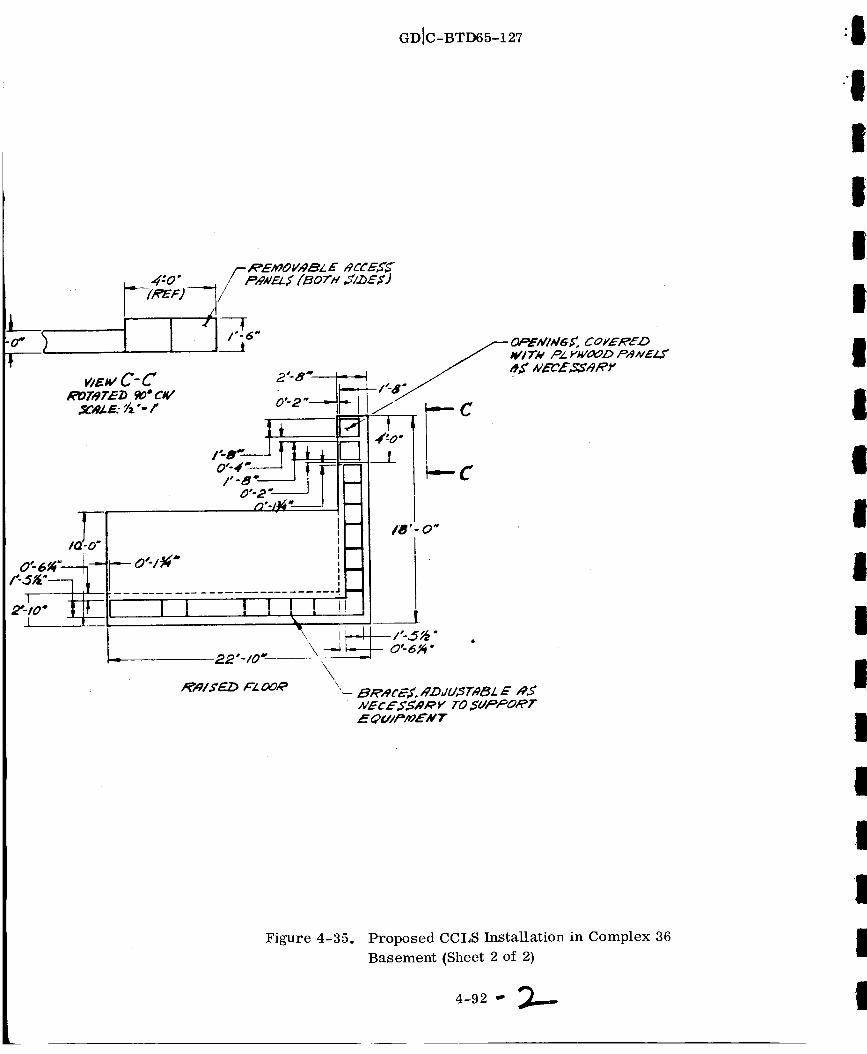
GDlC-BTD65-127
I I! i
ll
I I
I
I
Figure 4-35. Proposed CCLS Installation in Complex 36
Basement (Sheet 2 of 2)
4-9 2_

r
I
i2-i3_4
:678
• 9#0//
-#3
/5/6#7/8
]T£'HI
PRTEH RAC_"
>#tZXdZ#aPRYEL EC TRONIt.S
' _lH#TtelM/T2
.._M3"T£,¢#._ZOi_#C l-/#IT51,4VfF#UNIP5
I M/V/T #
U,'VIT 2.CIIM_CIT"ERZDG/C /./#IT 5
UNIT4t tJa##T5
._ENT_gL COArT#_O_dN#f _t_ULC_Z_TYPEC_ _E_E, VTAPY/Z)/.._,oz,ey _r,eT/o_vT_J_.E #ORE.9
I_EFZ_ES
103##OJ8#oJ_
k POWER R>EOUI6_EI//ENT, I:,_ ll_ P_ GO cYc,I..K,e,,WP 1"20_mp DE#V/CEJ
N,_RD _#_'E_(3 WIPE).
It_W/RE) #/,gRDWIA'_Z)A_ ,.RP/,IN%E 2_ Y/tC 60CYIP, ,5"4NP [15"gNP S'EPVIC[)
6_4i[11_'_PL M._ _(_OrJA/._,) ,v,4RZ) _VlPE D.
CzJadNECTC_4_.HUS_E4..._'_62 --/_ 115 ¥AC, 60 C_ 10,,gasp
CC1NNECTO#_:HU_EZ 5262
41'/£'E /16B,e'_,eKE_,_)
,_PN,_SE, 20_ f,qC,6_ C_ JA/#IP I#9,_11##,._',,P,I//CE.,)f4##IA_EJ I#_R'_ #V/PED.
N/G,A_LREQMIREMENTS=
•_ _ LIWE_,, JPPS coe2NTZ>O_'AVTI,e_E. lO_,il CU#P/P_N_{E_TTER Ci_ CatTNODE F_Z LOWE#_ _£#TPMT)
{EN//7"7"ER 0_" C_TN02_" FOL£ Om/E#P OUT#_zirac
L_L)PLEXOMTZET_ O/V FLL_
q67-4 _E_Po#v_ /_LE PO_ _'_O C c ._EMENT7_/5" n-Et4.
._ Gp/C FLJI_NISJ,]E._ T_._/vIlNAT.'.T,NAN, CO#/VE'CTO_- P.TSGSE--ZC-.;/G_. CON�VECTOR- /_5-3516_-88D

/.3 /2
_'6"- _',a' o._l. _._.,
/I I0 9
-_-,,_. /

I
Il
lII
il
Il
l
li
I
INTERFACE ]
E LE C TRONICS
RACKS (2)
FACILITY
POWER
GD]C-BTD65--127
TEST
POINT
PANEL
BACKUP A/B
GUIDANCE
SYSTEM
GUIDANCE
PATCH
PANEL
NO. 2
ATE -2230
GROUND
TEST SET
(iiRACKS)
GUIDANCE
PATCH
PANEL NO. 1
Figure 4-36. CCLS Interface
4-93
3°IGUIDANCE
GSE
_BEXISTING
CABLE RUN
36A
fCABLE RUN 36B
36B
GUIDANCE
GSE
GDIC-BTD65-127
Guidance patch panel No. 2 is provided to allow the interface electronics to be easily
wired and easily changed. It provides an additional advantage in that all of the outputs
from the ATE-2230 (digital-to-analog converters, SKS, etc. ) can be initially termi-
nated in a flexible manner. Thereafter, any changes to the guidance system's inter-
face characteristics will not disturb the ground computer's main machine wiring.
All of the signal wiring between patch panels 1 and 2 will be routed to a test point
panel. This will allow manual monitoring (using an oscilloscope or a digital voltmeter)
of all CCLS input signals.
4.7 SYSTEM CALIBRATION. The gyro drifts and accelerometer bias and scale
factors of the Centaur guidance system must be calibrated prior to flight so appro-
priate compensations during flight can be provided. Calibration is performed by posi-
tioning the platform in a series of orientations in such a manner that one or more
gyro and accelerometer parameters can be observed and determined. Mathematical
equations to determine these parameters are developed and coded to form a computer
program commonly called the preflight program. This program, which is presently
stored within the guidance computer, is to be incorporated into the ground computer
to calibrate the guidance system. No attempt has been made herein to describe the
program functions in detail, as they are fully explained in any of the preflight reports
(References 4, 5, 6, 7, 8).
Prior to the initialization of system calibration the inertial platform must be coarse
aligned to the desired orientation prescribed for one of the six calibration modes.
Calibration actually begins when one of the six calibration modes in the preflight pro-
gram is initiated. Each mode is divided into eight computational phases. The
operator will be made aware, by the display, of the align mode number and phase of
operation.
The present preflight program is designed to calibrate 12 of the 19 d-values leaving the
spin-reference axis mass unbalance drifts (d12 ' 15, 18 I' the accelerometer input axis
misalignments (d4, 5, 6), and the azimuth misalignment for the u accelerometer (d19),
to be determined by optics.
The scope of the present preflight program can be extended to determine d12 ' 15, 18
and d4, 5, 6 automatically without the use of optical equipment. The following sectionsdiscuss two possible techniques for determining the gyro mass unbalance spin-reference
axis (MUSRA) drifts and the accelerometer input axis misalignment. If error analyses
of these techniques prove satisfactory, the CCLS will be used to implement calibration
without optics.
4-94
-II
I
IIIl
II
iII
I
I
IIII

GDIC-BTD65--1_
I
I
II
4.7.1 MUSRA by Azimuth Alignment Technique. This technique requires that the
effective MUSRA drift be acting on the azimuth gyro with its input axis vertical, as
shown in Figure 4-37. The presence of MUSRA drift on the azimuth gyro, ff uncom-
pensated, will cause the platform to drift about the azimuth axis. As this happens the
east and north gyros sense a change in earth-rate components _ cos _ sin _ and G cos
cos _, respectively, where _ is the total azimuth misalignment angle due to the
initial azimuth coarse alignment and the uncompensated azimuth gyro drifts. The
I A
' TI, sT. o 7N
I|
I
I
!Figure 4-37. Platform Orientation for MUSRA Evaluation Using
Azimuth Alignment Technique
II
I
I
changing earth-rate component acting on the east gyro can be readily determined by
holding the east axis level with the north gyro and sampling the north accelerometer
outputs in a similar manner as the present technique of determining the azimuth mis-
alignment. This new method uses three velocity samplings instead of two as is pres-
ently employed. These velocity samples can be mathematically represented in the
same form as is used in Reference 4. They are:
VN1 g f_ T1= (¢EO + 6 w E t) dt
T O
(4-6)
!|
4-95

where
GDIC-BTD65-127
VN2
VN3
T 2
= gfT 0
T 3
= gfT 0
(¢E O + 5 0¢E t) dt
(¢EO + 5u_E t) dt
(4-7)
(4-8)
VN1, 2, 3= Velocity measured from the north axis during sampling
time T1, 2, 3, respectively, assuming time (To), and
velocity (VNo) are initially set to zero before actual
sampling takes place.
= Velocity sampling time intervals.T1, 2, 3
g = Local gravity.
CEO = Initial off-level angle of north accelerometer input axis.
6 u_E = Total uncompensated east gyro drift.
The uncompensated drift influencing the east gyro during the velocity sampling periods
can be expressed as
6W E = A(FT) E + A(MUIA) E + A(MUSRA)E + _ cos k sin _ (4-9)
where
A(FT)E = east gyro uncompensated fixed torque drift.
A(MUIA)E = east gyro uncompensated input axis mass unbalance drift.
A(MUSRA)E = east gyro uncompensated spin reference axis massunbalance drift.
= earth rotation rate.
k = local geodetic latitude.
4-96
I
I!
III
I
!II
II
II
I
Ill

-
I-.
I
!I
I
I
lI
lI
II
II
lIi
I
GD]C-BTD65-127
= azimuth misalignment angle about the azimuth gyro input axis.
cos _, sin _ = east gyro uncompensated drift due to azimuth misalignment
during velocity sampling period.
The azimuth misaiignment angle is dependent upon the initial coarse alignment of the
azimuth axis and the uncompensated azimuth gyro drift. It can be expressed as:
where
T
= @AO + f 6 _Ad_ (4-10)
T o
CAO = initial azimuth misalignment of east gyro input axis from due
east direction.
where
a. T 3 = 3T 1
b. T 2 = 2T 1
A(FT)A = azimuth gyro uncompensated fixed torque drift.
A(MUIA)A = azimuth gyro uncompensated input axis mass unbalance drift.
_(MUSRA)A = azimuth gyro uncompensated spin-reference axis massunbalance drift.
_E = vertical off-set angle due to uncompensated east gyro drift duringvelocity sampling period.
From the Equations 4-6 through4-11, and with the assumption that:
4-97
5 _A = uncompensated azimuth gyro drift.
The uncompensated drift influencing the azimuth gyro during velocity sampling can be
expressed as
6_ A = A(FT)A + A(MUIA)A + A(MUSRA)A + a[cos(k+¢E)-COS k] (4-11}

GDIC-BTD65-127
C. cos(k+¢E)- cosk_ 0
d. A(MUIA)A _- 0
e. A(FT)A _. 0
the final equation to determine the MUSRA can be formulated as
3VN1 - 3VN2 + VN3
A(MUSRA)A = g_ cos ), (T1)3
(4-12)
The terms tbEO, CAO, A(FT)E, A(MUIA)E, and A(MUSRA)E have been eliminated in
the process of deriving Equation 4-12.
4.7.2 MUSRA by 45-Degree Offset Drift Off-Level. This technique requires a
platform orientation in which the accelerometer input axes in the east and azimuth
plane are positioned 45 degrees off the level plane (see Figure 4-38). The north
axis is allowed to drift off-level under the influence of the MUSRA drifts of the u
and w gyros.
The MUSRA driftscan be determined by sampling the velocity from the north acceler-
ometer during a specific sampling period. From the velocity information mathemati-
cal equations can be formulated to determine the MUSRA driftautomatically instead
of using optics.
A
_I S
O S ._O i
45
NLEVEL REFERENCE
Figure 4-38. Platform Orientations for MUSRA Evaluation Using 45-Degree
Offset, Drift Off-Level Technique
4-98
-.lill
II
!III
I
!II
IIII
I
IIii!
I

:
!
I
i
i
I
l
lI
II
lII
I
lI
lt
GDIC-BTD65-127
4.7.3 Accelerometer Input Axis Misalignment by 45-Degree Offset from Level.
This technique requires a platform orientation shown in Figure 4-39. The plat-
form is initially aligned so the accelerometer input axes, whose relative misalign-
merit is to be determined, are approximately 45 degrees off level. The axis on the
level plane (V-axis in Figure 4-39) must be held level while velocities are being
sampled from off-level accelerometers u and w over a predetermined period of
time, T. The velocity information Vu and Vw collected can be used to determine
_1 and _2, respectively, since u and w accelerometer input axes are in this case
restricted by design to move together about the V axis. Then it is obvious that:
_2 + Puw + _1 = 180 degrees, Puw is a constant, and
where
°1 l(Vu)_'_ (4-13)
,: (;_w/ 14-14)
V = D V +d T (4-15)u 1 (Yu 7
V = D V +d T (4-16)w 3 (_w 9
_2 @1 LEVE L RE FERENCE
V
Figure 4-39. Platform Orientation for Accelerometer Input
Axis Misalignment Evaluation
4-99

GDIC-BTD65-127
The angle Puw can be expressed as
Puw=_°°-[% _ +(%>AV_]AVE(4-17)
By definition,
d5 = (Puw - 90°) (0.01745329) radians (4-18)
d 5 = 0 when Puw = 9¢
> 90 °> 0 when Puwd 5
d 5 < 0 when Puw < 90°
The accelerometer input axes misalignments Puv and Pvw can be determined in asimilar manner and mathematically represented as:
d = (p - 90) (0.01745329)6 vw
(4-19)
d4 = (Puv - 90) {0. 01745329) (4-20)
4.7.4 Summary of Calibration Without Optics. The evaluation of MUSRA by
Method 1 seems to have the advantage over Method 2 that it can be accommodated by
the present six calibration modes without any change to platform orientation or hard-
ware. However, it requires an additional phase in three of the six calibration modes.
MUSRA by Method 2 requires changes to present platform orientations. This can be
incorporated by using the three test align modes (functions of which are no longer
required in the preflight program based on AC-8 ground rules) with different platform
orientations.
The automatic evaluation of accelerometer input axes misalignments requires change
to present platform orientations. It can be easily implemented by changing the plat-
form orientations in the three test align modes (functions of which are no longer needed
in the preflight program based on AC-8 ground rules).
4-100
:!
II
!II
II
!I!
III
IIII
iI

:
I
II
IlI
lI
lI
lI
l
Iil
li
GD 1C-B TD65-127
SEC TION 5
THE FEASIBILITY DEMONSTRATION
The main objective of the feasibility demonstration was to use automated test equip-
ment to checkout the Centaur guidance system. The ATE-2 system alone provided the
command and control function required; the existing guidance system GSE was not used.
A cross-section of the functions accomplished by the present guidance system GSE was
chosen for implementation.
The two primary reasons for the feasibility demonstration were to determine whether
a system using an SDS computer could be used to checkout a Centaur guidance system,
and to discover any hardware or software problems associated with the ATE-2 when
used in this manner. Having investigated these areas, a base for the final hardware
and software configurations for the CCLS was obtained.
There were three phases involved with implementing the feasibility demonstration.
First, the special hardware to be used in conjunction with the existing ATE-2 test set
had to be fabricated. Second, the signals and power had to be routed between the
guidance system and the ATE-2. Finally, the SDS 910 computer section of the ATE-2
system had to be programmed to control and test the guidance system.
5.1 FEASIBILITY STUDY GROUND RULES. Several ground rules had to be developed
for building special hardware for the ATE-2 system:
a. No hardware was to be built that would interfere with autopilot testing. This
philosophy was adopted because the ATE-2 system is used extensively for pro-
duction acceptance tests on Centaur programmers.
b. The availability of parts and the time needed to develop special hardware circuits
were important considerations. The development of a special-purpose circuit
would usually result in an efficient operation, but might needlessly delay the
demonstration. Therefore, if a task could be done with means already available
on the ATE-2 system, the existing hardware was utilized and the possible losses
of speed and efficiency of operation were accepted. The development of high-speed,
reliable circuits was left to be accomplished in the final configuration.
c. The signal and power routing between the guidance system and the A TE-2 was
accomplished in a manner that would not disturb the versatile nature of the ATE-2.
This was done by building special cables to connect between the two systems, and
by routing all signal flow through a patchboard. Changes, from checkout of the
guidance system to checkout of an autopilot programmer, required only an ex-
change of patchboards and reconnection of six cables.
5-1

GDIC-B TD65-127
d. The guidance system test functions chosen for implementation in the feasibility
demonstration were a cross-section of all test functions normally accomplished
by the GSE. The following list itemizes the functions performed by the ATE-2
system:
1. Supply and control the application of power to the guidance system.
2. Monitor (and give an error signal, when required) voltages coming from the
guidance system.
3. Command and monitor partial guidance computer functional test including
Order Code and Memory Sum Tests.
4. Perform remote load and read communication function.
5. Perform coarse-alignment function.
6. Command fine alignment.
Although the feasibility demonstration formed a base for the final configuration of the
CCLS, there are some major differences between the two systems. Other than a
computer-controlled typewriter, there was no display system for the ATE-2 demon-
stration. Further, there were no modifications made to the flight computer programs
to accommodate the feasibility study, as this would have rendered the airborne soft-
ware incompatible with the existing GSE.
5.2 POWER CGNTROL. Power control, for the feasibility study, consisted of
supplying and monitoring +28 VDC and 115 VAC, 400 CPS, to the guidance system. In
supplying prime AC and DC power to the guidance system, manual relays with high
current carrying contacts were used. The ground rule of noninterference with auto-
pilot testing prevented converting these relays to program-controlled devices. Lower
current power control signals (i. e., power sequencing commands to the airborne com-
puter) were, however, supplied from the ATE-2 with relays controlled by the program.
Skip-if-signal-not-set (SKS} lines were used to monitor the presence of voltages on
control lines. All nonairborne computer power sequencing was accomplished manually,
since the programs to automate this function had not been fully developed.
When two or more relays were automatically latched in succession (during turn-on of
the airborne computer}, a minimum programmed delay of 20 milliseconds was placed
between relay latching commands to avoid "relay race" conditions. The first program
written accomplished this delay by using the known, fixed time to execute a series of
dummy instructions. However, it was found that this subroutine totally locked-up the
SDS computer until the delay was completed. (The SDS computer could not execute
any other programs until the required delay had elapsed. This was acceptable for 20-
millisecond delays, but not for delays of the order of minutes.) As a result, another
way of obtaining the delay was programmed using the clock and the interrupt system.
5-2
:1
1
II
II
II
II
III
I
i
I
I
I
I

I
II
I
I
II
III
I!
l
Il
ll
GD I C-BTD65-127
The ATE-2 is hard wired to give an interrupt every ten milliseconds if the clock is
running and the interrupts are enabled. The computer was programmed to count these
interrupts, thereby recording time without restriction to only this one task. The use
of this technique simplified the programming of a 90-second waiting period during
which the flight computer drum accelerated to operating speed after turn-on.
5.2.1 Computer Power Control. Airborne computer power could be applied inde-
pendently of the remaining guidance system components. The airborne computer
turn-on sequence was:
a. ATE-2 test set power ON (manual}.
b. Reset all ATE-2 relays (automatic}.
c. Set MODE 28 on mode lines (automatic).
d. +28 VDC prime power to airborne computer (manual).
e. +28 VDC to Stop Inhibit Line (automatic).
f. 115 VAC, 400 CPS, prime power to airborne computer (manual}.
g. +28 VDC to Drum Run Up Line (automatic}.
h. Wait 90 seconds for drum to run up (automatic).
i. +28 VDC to the U3 Line (automatic).
j. Float Drum Run Up Line (automatic}.
k. Simultaneous ground to Stop Inhibit Line and +28 VDC to Run Line (automatic}.
A flow diagram of the program that controls this sequence is shown in Figure 5-1.
All program-controlled relays were commanded by the SDS computer through the use
of energize-output-module (EOM) instructions. Two EOM instructions were needed to
latch any relay; the first (set EOIVl) was used to set up the logic for the particular
relay to be executed, and the second (execute EOM} was used as a master gate com-
mand to achieve latching. Using this technique, any number of relays could be
commanded to simultaneously latch. This method was also used to set up mode code
28 on the nine mode lines during the airborne computer turn-on sequence.
All manually-operated relays were monitored by SKS lines. When the program
reached a step that required a relay to be set manually, a typewritten instruction was
provided to the operator. The SDS computer would proceed to the next sequential step
only after the SKS line confirmed that the operator had taken the required action.
5.2.2 Airborne Computer Reinitialization. It was found desirable to have the
capability of reinitializing the airborne computer's program. This task could most
easily be accomplished by switching the airborne computer from its normal RUN
5-3

GD I C-BTD65-127
TYPEWRITE R
MESSAGE:
TURN ATE-2
TEST SET
PWR ON
+28 VDC
TO STOP
INHIBIT TYPE MESSAGE:
"TURN ATE-2
TEST SET
+28 VDC ON"
_r
TYPE MESSAGE:[ _ _YES
"TURN 400 _ 4uu _CL_
I I_°
+28 VDC TO
DRUM
RUN-UP
GROUND TO
STOP INHIBIT
+28 VDC TO
RUN LINEFLOAT DRUMRUN-UP LINE
Figure 5-1. Airborne Computer Power Turn-On
5-4
RESET
ALL
RE LAYS
_r
!
SET MODE 28 [
ION MODE
LINES
WAIT 90 SEC
FOR DRUM
TO RUN-UP
r
+28 VDC
TO U3
LINE
:1
|
I
I
I
I
I
I
I
I
!
I
I
I
I
I
I
I
I

II
III
I
Il
iI
III
II
II
GD IC-BTD65-127
state to its STANDBY state and then back into RUN. This action caused a fixed pattern
to be input to the computer's instruction register, thereby forcing the computer to
branch to execution of the Order Code Test. The subroutine written to accomplish
this branching caused two ATE-2 power control relays, which controlled the Run
and Stop Inhibit Lines, to operate. The first half of the subroutine, which placed the
airborne computer in a STANDBY mode from the RUN mode, utilized three EOM's:
EOM
02 32260
02 30720
02 32640
DESCRIPTION
Reset relay to float Run Line
Set relay to place +28 VDC on Stop Inhibit Line
Execute relays
After these commands were executed, the SDS computer program delayed for one
second to ensure that the flight computer had gone to the STANDBY mode. The sub-
program then executed three EOM's to place the flight computer back into the RUN
mode.
02 30740
02 32240
02 32640
Reset relay to ground Stop Inhibit Line
Set relay to place +28 VDC on Run Line
Execute relays
Execution of this series of commands placed the airborne computer into the Order
Code Test, from which it could branch to any other test mode when commanded by the
test set.
5.3 COMPUTER FUNCTIONAL TEST. After completion of the computer power
turn-on sequence, the SDS computer program entered the airborne computer functional
test sequence. A flow diagram of this mode is shown in Figure 5-2.
The functional test was separated into two parts, the first of which was the Order Code
Te_to Tmme6,_'ate!y _ev the flight _nmnut_r rmWp.r _pp]ie._tion .q_qu_ne._. wan completed.
the flight computer program entered the Order Code Test subroutine, a self-check
that verified all the arithmetic commands of the flight computer were working properly.
Each time this subroutine cycled successfully it sent out a G4 discrete. The Order
Code Test was monitored by counting G4 discretes with an SKS for 30 seconds, using
the clock as a timing base. If the discrete count was 600 • 10 percent, the SDS
program typed a message indicating passage of the test. (The tolerances used were
chosen for demonstration purpose only.) If the count was out of tolerance, the SDS
computer program would type out the error and would then stop.
5-5

NO
COUNTG4DISCRETESFOR 30SEC
GROUND ]TO MODESET LINE
v
Figure 5-2.
GD IC-BTD65-127
YESv
TYPEE RROR
YES
ISSUE
MODE
SET
Ii
III
I
IIII
I
II
YESv
II
YEs._i TYPE"i ERROR
Airborne Computer Functional Testing
5-6

I
i
II
II
II
II
III
I
II
i
GD 1C-BTD65-127
After the Order Code Test was successfully completed, the mode set relay was set
and executed to supply +28 VDC to the Mode Set Line thereby commanding the airborne
computer into the Memory Sum Test. (Mode code 28 had been placed on the mode
lines during power application.} The SDS program interrogated the G3 line for two
seconds. If a G3 discrete was not sensed within this time, an error indication was
typed out and the SDS computer stopped.
If a G3 discrete was sensed within the specified time, the mode set relay was reset
and executed to supply a ground to the Mode Set Line. The SDS program then entered
a two-minute wait phase. If either G1 or G2 or both were not received within this
time period an error indication was typed and the SDS computer stopped. If both of
these discretes were sensed during the interval, the SDS program accepted them as an
indication that the memory sum was completed and was correct. The program would
then type out a statement indicating passage of the test.
Upon exiting from the memory sum routine, the airborne computer entered an idle
loop that could only be left by commanding the computer to STANDBY and then back to
RUN. (This exit was peculiar to the AC-5 program which was used for the demon-
stration. All other programs normally exit to the Order Code Test at the conclusion
of memory sum.) This series of commands was called by branching to the reinitiali-
zation subroutine.
5.4 GROUND TO NAVIGATION COMPUTER COMMUNICATION. The feasibility
study accomplished ground to airborne computer communication using the AC-5 RL&R
program in the same manner as does the existing RL&R equipment. For communica-
tion, the nine mode lines normally used to command the airborne computer to its
various modes were used to send We airborne computer both the data to be stored and
the fill and read instructions. The Mode Set and the Steering Alert Lines were used to
command fill and read operations during the RL&R mode. The G1 and G3 Discrete
Lines were interrogated by the ATE-2 system for an indication of a fill or read oper-
ation in process or completion. The telemetry line was used to read data from the
airborne computer. A set of constants (D and J values) was chosen as the data to be
transferred to and from the airborne computer. No effort was made to modify the
existing flight hardware or software in implementing ground-to-navigation computer
communication.
The communication interface between the ground and airborne computers consisted of
1 telemetry buffer for reading airborne computer data, 11 relays from the relay bank
(including 1 for Mode Set, 1 for Steering Alert, and 9 for the Mode Code Lines), and
2 SKS lines for sensing the G1 and G3 discretes. The lines of communication between
these devices and the two computers were routed through the patch panel and the
special cables prepared for guidance system control.
Four steps were involved in utilizing the communication capability with the ATE-2
system. First, the SDS 910 computer core memory was loaded with a set of D and J
5-7

GDIC-BTD65-127
values using either the typewriter or the card reader. Second, the D and J values
were communicated to the airborne computer by employing the relay bank and the SKS
lines. Third, a means to receive the D and J values from the airborne computer was
implemented by using the SKS lines and the telemetry buffer. Fourth, the D and J
values were displayed on the typewriter. An indication of any nonverification was
provided when the data read back from the airborne computer did not agree with that
stored in the SDS memory.
5.4.1 Loading SDS Memory with Data for Communication. In filling the SDS memory
with data from the typewriter or the card reader, the standard airborne computer
word format (T_ - TB - S_ - S_ - ORD) was used. Each card or typewriter line con-
tained an alphanumeric identifier, a data word, a read instruction (T_ - S_) and a fill
instruction (T_ - S_), as shown in Table 5-1.
Table 5-1. SDS Data Input Format
I
I
IlI
II
IDENTIFIER
DI6
DATA WORD
Ta T_ S_ S_ ORD
31 31 63 63 7
READ FILL
31 63.! 31
63
The information was read into the SDS computer, separated, and placed into four
storage tables in SDS memory. Each of the storage tables consisted of 64 24-bit
words. The first table was used for starage of the alphanumeric identifier and
for control in case the operator desired to read, fill, or inspect a particular D or J
value within the tables. The second and third tables were usedto store the data word.
(Since the airborne computer has a 25-bit word and the SDS computer has a 24-bit word,
each airborne data word was separated into two SDS words.) For programming con-
venience, T_ and Tfl {ten bits) were placed into Storage Table Two; and S_, S_, andORD (15 bits) were placed in Storage Table Three. Storage Table Four was filled with
the read and fill instructions.
A portion of the process of storing data into the SDS memory (from typewriter or cards)
was to change the data format from that of the airborne computer (most significant bit
to the right) to that of the SDS (most significant bit to the left). This same conversion
was necessary when receiving data from the airborne computer. To solve this prob-
lem, a subroutine was written that inverted data being transmitted to and from the
airborne computer. Once the data had been inverted, it was presented to the airborne
computer, five binary bits at a time, via the Mode Code Lines. Ten such sets of five
binary bits were presented for each fill operation, whereas only five sets were
required for a read operation.
5-8
II
III
III
i
III

GD] C-BTD65-127
!
t
!
!
5.4.2 Data Communication to the Airborne Computer. After all the D and J values
had been read into the tables in SDS memory, the data was sent to the airborne com-
puter. To do this the airborne computer had to be placed in the RL&R mode. This was
accomplished by commanding mode 27 on the Mode Code Lines and +28 VDC to the Mode
Set Line. To ensure that all relay bounce had cleared from the mode control lines (so
that the airborne computer would not be required to sample noisy lines and possibly
interpret data erroneously), +28 VDC was placed on the Mode Set Line 50 milliseconds
after the mode control lines had been executed. As soon as this sequence had occurred,
the SDS computer entered a 500-millisecond wait phase, during which the G1 line was
interrogated by an SKS. If within this time the SKS did not sense a G1 discrete, a
message was typed indicating a malfunction. If the SDS computer did sense the dis-
crete within the required time, it would start a sequence of filling the airborne com-
puter with information.
5.4.3 Data Readout from the Airborne Computer. The read capability was imple-
mented by using relays to communicate with the mode lines and a telemetry buffer
specifically designed to accept the transmitted data from the airborne computer. The
relay control was mechanized in a manner identical to the fill capability. In this case
five sets of five binary bits of data were transmitted to the airborne computer. These
25 bits of binary information dictated which airborne computer word was to be read.
5.4.4 Display of Data. After the telemetry buffer contents had been stored in SDS
memory the data had to be inverted so it could be typed out in the familiar airborne
computer format. The display contained the data read in, the data read out, the fill
and read locations, and an error indication if the data read did not identically compare
with the data filled. The format of the typewritten output is shown in Table 5-2. (Note
that the two ORD sections disagree, hence an error indication is presented. )
Table 5-2. Communication Display Format
_TY SDS DATA
o..I D14 03 12 41 63 7
!
!
!
ERROR A/B DATA READ FILL
• o..03-12 41 63 6 28 - 18
5.5 GIMBAL COARSE ALIGNMENT. The coarse-alignment function is mechanized
in the manual GSE by slaving three airborne resolvers, mounted on each of three gim-
bals in the inertial platform, to three resolvers mounted in the ground support equip-
ment. The ground resolvers are then rotated with motors through a gear reduction
system, thereby causing the airborne resolvers to follow. Suitable readout of angular
motion from the ground resolvers allows the operator to rotate the gimbals to any
desired orientation (see Figure 5-3).
!
!5-9
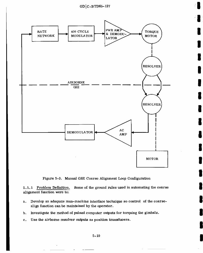
GD IC-BTD65-127
RATE
NETWORK
400 CYCLE
MODULATOR
AIRBORNE
GSE
DEMODULATOR
I
I
, I' I
I-- I
II
I I
Ii I
MOTOR
5.5.1
alignment function were to:
Figure 5-3. Manual GSE Coarse Alignment Loop Configuration
Problem Definition. Some of the ground rules used in automating the coarse
a. Develop an adequate man-machine interface technique so control of the coarse-
align function can be maintained by the operator.
b. Investigate the method of pulsed computer outputs for torquing the gimbals.
c. Use the airborne resolver outputs as position transducers.
5-10
III
III
I

K
I
I
!
I
I
II
II
II
II
I
I
GD I C-BTD65-127
d. Develop a program that would be capable of both automatic gimbal alignment
sequencing for the six calibration modes and a gimbal slew test.
5.5.2 Gimbal Torquing Software. Ground rule "a" was satisfied by deciding what
control the operator should have over the coarse-alignment function. For this study
the coarse-alignment control routine was a subroutine of the main align mode control
program. Therefore, the operator interface to coarse alignment, itself, was non-
existent. Upon entering the mode control program the computer was programmed to
output, on a typewriter, the following series of control statements for program
vectoring:
a. Set Breakpoint 1 for align modes 1 through 6.
b. Set Breakpoint 2 for a normal calibration and final align.
c. Set Breakpoint 3 for a gimbal slew test.
Setting Breakpoint 1 caused the program to output another control statement telling
the operator to input, on the typewriter, the align mode requests in a particular format.
The requests would then be typed out on the typewriter to verify that the proper modes
had been input.
Setting Breakpoint 2 resulted in align modes 1 through 6 plus final align being executed.
Setting Breakpoint 3 caused execution of a gimbal slew test with controlled stops at the
beginning of the clockwise and counterclockwise slew so that a Sanborn recorder or
other display equipment could be properly set up before test initiation.
Other programmed options were made available during the calibration modes to allow
the operator to accomplish tasks such as optical verification.
Ground rule "b" was necessary since the SDS 910 computer did not have any digital-to-
analog output devices available. The pulsed output lends itself to the coarse-alignment
control problem since it does not require any special resetting to obtain a zero output.
The pulsed output is available through the EOM command. When this software command
is given, a discrete pulse, approximately eight microseconds wide, is output from the
computer. This output is then used to trigger a one-shot; the one-shot in turn is output
to the gimbal control amplifier to effect a torque on the gimbal. After the preset time
of the one-shot, the torquing voltage returns to zero, thereby requiring no program
servicing except for the original EOM.
The gimbal resolver outputs (reference ground rule "c") are available in the present
airborne hardware for use in controlling the coarse-alignment function. The outputs
of the resolvers were demodulated and input to the analog-to-digital converter (see
Figure 5-4). A software routine sampled the digital outputs and formed an error
5-11

GD I C-BTD65-127
RATENETWORK
PULSED
TORQUING
OUTPUT
DEVICE
400 CYCLE
MODULATOR
AIRBORNE
ATE -2
COMPUTER
LOGIC
& DEMODU_
!
I
400 CYCLEDEMODULATOR
MULTIPLEX &ANALOG-TO-DIGITAL
CONVERTER
A COS ¢
Figure 5-4. ATE-2 Gimbal Alignment Control Diagram
equation that was used to control gimbal rate and position by outputting torque to the
gimbal control amplifiers. Ground rule "d" is self-explanatory.
Figure 5-5 shows a block diagram of the operating sequence of the coarse-alignment
function as it was implemented (as a part of the fine-align mode control program).
The program initially outputs, via the typewriter, a series of control statements which
inform the operator of the available control choices. The operator must then enter
his choice, either by setting breakpoints or using the typewriter. Subsequently, the
input request is both stored in the computer and typed out on the typewriter for oper-
ator verification. The program then selects the proper gimbal angles for the coarse-
5-12
II
II
!1I
IIII
!
II
i
I
iiIIl

III
II
II
IIII
Il
II
I
II
0
z
z(y
Z
k_Z
°__Z
GD IC-BTD65-127
A
_/ _\\ _ /__
o_o<r_
O_
r_ 0
Z
-_ _o _
L
0
5-13
oo
b_o
o
o
o
<
o
o0
I
co
o

GD I C-BTD65-127
alignment function, tests to determine whether all requested align modes have been
completed, and coarse aligns the gimbals to the proper angles.
The operator controls, via breakpoints, whether the program will exit or continue to
the fine-align mode once the coarse-align function has been completed. If a continua-
tion to fine align is requested, the program cages the fourth gimbal, when required,
and proceeds to command the airborne computer to control the fine alignment. A
breakpoint test for calibration exit (to allow optical verification or to exit to the next
mode request} is also included. When the sequence has been completed, the computer
prints out "requested function completed" on the typewriter.
Figure 5-6 is a block diagram of the coarse alignment control program which was used
for the feasibility study. The sequence starts with the computer reading the multi-
plexer to determine the gimbal sine and cosine functions from the airborne resolver
outputs, and thereby determines the quadrant of the gimbal. The program then linear-
izes the sine or cosine so that a solution for the angles is unnecessary. (This program
used the first 45 degrees of the sine or cosine function as an approximation to a straight
line and pieced these segments together, with proper inverting, to form a continuous
ramp over 360 degrees of resolver output}. The coarse-align command angles are then
compared with the gimbal quadrants to determine the shortest path to the next gimbal
orientation.
A test is also included to determine whether the gimbal is 180 degrees out of phase.
If it is, the null test is bypassed at that point. If a true null is being sought, the pro-
gram enters the null test. Since all align modes use cardinal orientations, the
resolver outputs are used as nulling functions. The program assigns the proper
nulling function (sine or cosine) to the coarse-align command angle. In order to per-
form this function, the multiplexer is re-read four times and averaged to update the
gimbal resolver outputs.
The rate control function is selected on the basis of which angle is smaller, cosine or
sine. This ensures that the gimbal rate is being controlled with the function that is
less than 45 degrees. Having determined the controlling function, the required gimbal
torquing rate is then calculated. If torquing is not required, the program proceeds
immediately to the next gimbal. If, however, torquing is required, the error equation
is calculated and the discrete torquing rate is determined and applied, using EOM's
to pulse the one-shots. The program torques all three gimbal loops simultaneously to
minimize the time required to coarse align the platform.
5.5.3 Gimbal Torquing Hardware. The hardware development to enable the one-shot
outputs to the gimbal control amplifiers was accomplished using standard SDS printed
circuit logic modules. Figure 5-7 shows a block diagram of the output hardware used
for gimbal torquing in the feasibility study. The pulse output from the DC amplifier is
smoothed by the RC filter.
5-14
III
III
I
I
I
I
I
I
II
I
I
I
I
I

GD IC-BTD65-127
I
I
IT
_D
!
I-
_ r.D Z _
[D
!
0
0
3__0
I
©
F_
tZn_ _1-
_Dz
t_
3
0 n0 •
3
%
/k
tm
©z
t_
blO
°,,,_
oo
°.,-_
<
°,-,.I
0
I
kO
o
5-15
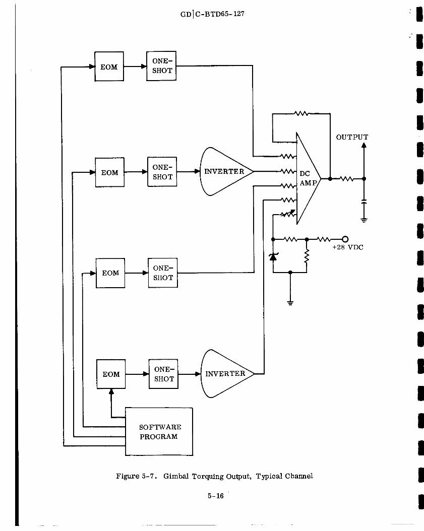
EOM
ONE-
SHOT
EOMONE-
SHOT
EOMONE-
SHOT
LONE-
SHOT
SOFTWARE
PROGRAM
Figure 5- 7.
GD IC-BTD65-127
INVE RTE R
Gimbal Torquing Output, Typical Channel
5-16
OUTPUT
+28 VDC
I
III
III
II
II
III
I
II
II

I
IiI
lI
II
II
II
IlI
I
lII
GD IC-BTD65-127
This method of implementation allowed nine levels of output (_+ 4V, _ 3V, ± 2V, _+ IV,
and zero), thereby allowing for zero-to-full torque out of the torquer motor. The only
other hardware required for the coarse-alignment function was a demodulator for each
resolver output signal. In order to operate within the time constraints of the feasibility
study, no time was expended in designing demodulators for this application; obsoleteAtlas autopilot demodulator circuit boards were used.
The coarse-alignment loop using the SDS computer performed satisfactorily during the
feasibility study. The main problem was encountered in maintaining continuous control
of the gimbals. This problem was adequately solved by filtering the one-shot outputs
with low-frequency single lag filters. A second problem, noise on the analog-to-
digital converter, was solved by digitally smoothing the resolver outputs.
Several methods of feedback control were used, including: rate, rate with position,
and position only. Better loop performance was accomplished using rate control,
although an adequate comparison of rate with position control versus rate control alone
is not available due to changes in the software between the time the two types of feed-back were used.
5-17

III
Il
I
Il
III
II
II
Il
II
0
.
0
.
e
e
.
0
GDIC-BTD65-127
SECTION 6
REFERENCES
F. I. Backus, A Study of Various Analytical Techniques for the Inflight Compen-
sation of Gyro Drift Rates, Report No. GDIC-BTD65-091, 31 May 1965.
R. F. Ringland, T. R. Bertolino, and J. B. Shaul, Final Report on Feasibility
Study to Determine Atlas/Centaur Flight Control System Changes, Report No.GD]A-BTD64-161, 23 October 1964.
J. A. Hughes, Specification for Centaur Electromagnetic Interference Control,Report No. GDtA-55-03016 , 4 May 1964.
J. Banks, General Concept of SCATE-HI Preflight Program for the Centaur
Guidance System, Report No. GDA63-0258, 18 November 1963.
T. C. Lee, AC-3 Preflight Equations for the Centaur Inertial Guidance System,Report No. GDIA-BTD64-051, 1 March 1964.
T. C. Lee, AC-4 Preflight Equations for the Centaur Inertial Guidance System,Report No. GDIA-BTD64-102 , 15 June 1964.
T. C. Lee, AC-5 Preflight Equations for the Centaur Inertial Guidance System,Report No. GDIC-BTD65-016, 30 January 1965.
T. C. Lee, AC-6 Preflight Equations for the Centaur Inertial Guidance System,
Report No. GDIC-BTD65-056, 20 April 1965.
6-1

I
II
i
I
I
I
I
II
i
II
III
I
GDIC-BTD65-127
APPENDIX A
BEST COMMERCIAL PRACTICE DRAWINGS
Best commercial practice (BCP) drawings, to be used to document the CCLS configura-
tion, will have minimum requirements as set forth in this section.
A. 1 POLICY
a. All engineering technical information communicated for subsequent action will be
documented in written form. This includes data for fabrication, testing, inspec-
tion, installation, maintenance, procurement, operation, and performance.
b. All BCP data must be numbered in an approved standard GD/C pattern, obtain-
able from a central source, so that it may be stored and retrieved as necessary.
c. All engineering data created to BCP requirements shall be subject to approval,
checking, and group release requirements.
d. Except where specifically prescribed or waived by these requirements, the GD/C
Drawing Room Manual (DRM) shall be used as a guide in preparing and processing
the data.
e. Data prepared to BCP requirements must lend itself to upgrading with a minimum
amount of conversion effort. Since differences in types are primarily quantitative
and are in the area of delineation techniques, upgrading shall be accomplished by
adding information to or improving the quality of documents, rather than by chang-
ing already existing information by completely redrawing.
A. 2 PREPARATION OF ENGINEERING DATA
ao Drawing Techniques - Design documentation media shall contain provisions for
recording identification (document number and title) and revision information.
The following delineation techniques may be used:
1. Sketches on blank vellum stamped with title and revision blocks. This is the
minimum requirement.
2. Layouts may be converted to drawings by stamping with title block and
revision block on the front. However, when it is planned initially to convert
layouts, they should be originally prepared to standard GD/C drawing format.
3. Photovellums may be made by incorporating photographs of blackboard or
pencil sketches, layouts, mockups, breadboards, or models into standard
GD/C drawing format.
4. Standard GD/C drawing format is preferred.
A-1

GDIC-BTD65-127
b. Drawing Requirements
1. Assemblies/installations of all levels may be depicted whether in the standardstructure (drawing next-assembling into higher level drawings}, or on a singlemultisheet or bookform drawing identified by a single drawing number, andconsisting of, but not limited to, schematics, assemblies, details, and aparts list.
2. The standard structure, where used, must be established during the studyphase in coordination with the operating department, in order to minimizethe need for tooling synthetic numbers, and to meet assembly and disassembly
requirements.
3. Schematics must be prepared for functional electrical systems.
4. Use of drafting conventions (dimension lines, lettering symbols, etc.} shall
be guided by the DtLM. Symbols and codes not covered by the DRM shall be
explained on the drawing.
5. Originals must be sufficient to produce legible prints.
6. Revisions shall be documented on drawings and parts lists by direct change or
by ECN. Interim revision procedures such as mark-up of a limited number of
prints, or creations of informal ECNs, may be used.
7. The "Title Block" stamp, when applied on blank vellum, shall include the
company name, location, and space for the following information:
a} Title
b} Drawing number
c} Contract number
d} Code Identification number
e} Signature for design, check, draftsman, and design engineer.
c. Delineation Requirements
1. All parts and material requirements shall be listed on parts lists (Form
A2604-1} except where integral lists of material formats are used. Parts
lists and advanced bills of material may be released for procurement incre-
mentally, as soon as requirements are fomulated. Parts lists must contain,
at a minimum, part number identification and quantities required. Usage
data may be maintained manually on separate parts lists or in application
blocks until the design is firm, at which time usage data shall be centrally
recorded for retrieval purposes.
A-2
I
III
iIIi
III
III
I
II
iI

g
i
i
!
i
!
i
!
|ig
Ii
a
GDIC-BTD65-127
o Part numbers shall be specified on parts lists in accordance with the followingrules:
a) For GD/C design parts - GD/C part numbers shall be assigned to all
fabricated parts except parts used in the building trades (channels,
structural angles, etc.) and details of inseparable assemblies orinstallations.
b) For Purchased Parts
I) Development Items - GD/C specification control drawings shall
always be used, per DILM 800.6.
2) Standard Commercial Items - GD/C specification control drawings
(SCD) shall be used when they exist. If no SCD number exists,
vendor identification and part number may be used, or an SCD
prepared.
3) Field of drawing, list of material, or parts list must identify all
required raw and bulk materials.
4) Callouts of existing controlled internal documents (i. e., MPS, EOP,
etc.), which are not engineering data, are permitted on drawings.
5) Documents and parts shall be identified in accordance with DRM 075
and 080 respectively.
6) All changes made to released drawings shall be controlled and
identified by change letters.
7) End items shall be identified for serialization, allocation, application,
and data retrieval purposes by End Item Description (EID) numbers,
assigned in sequence, in standard GD/C patterns (XX-XXXX-XX).
8) EID numbers without model prefixes (XXXX-XX) shall be used on
nameplates as end item serial numbers. Where required, an
identifying prefix may be used (e. g., STE XXXX-XX).
A-3

I
i=
III
II
II
II
II
II
III
i
GDIC-BTD65-127
APPENDIX B
PRECISION DC SIGNAL MONITORING CIRCUIT DESIGN
The circuit configuration to be used for monitoring DC signals from the guidance sys-
tem (via the analog-to-digital converter} will take the form shown in Figure B-1.
The control of transistor switches 1 and 2 is such that when one switch is turned full
on {saturated), the other switch is turned off (driven into the cutoff region). The
capacitor is used for filtering out noise. The DC amplifier buffers the signal between
the signal source and the analog-to-digital converter. This serves a threefold purpose:
a. Permits the input impedance of the multiplexer to be adjusted.
b. Presents a low-impedance input to the anaolog-to-digital converter.
c. Adjusts the gain of the amplifier that will control the signal level. This will per-
mit the signal level to fall within the maximum range of the analog-to-digital con-
verter (+ 10VDC).
GUIDANCE SYSTEM
R1
IN--_ R3:
[--m umlm_m
I FILTER IIII
I R2
III c:IIII1
MULTIPLEXER1
i II Rf I
IIt__TRANSISTOR _ 1
SWiTC__ I! I ,II T_NS_TORI_T I
I1 i1_ 1
O CONTROL
EIN = DC SIGNAL TO BE MEASURED
R = ISOLATION RESISTOR1
R 2 = GAIN ADJUST RESISTOR
R 3 = ATTENUATION RESISTOR
R M = MULTIPLEXER INPUT RESISTOR
Rf = MULTIPLEXER AMPLIFIER FEEDBACK RESISTOR
C = FILTER CAPACITOR
'ii ANALOG-
TO-
DIGITAL
CONVERTEREDC
A
Figure B-1. DC Signal Monitoring Circuit
Configuration
B-1
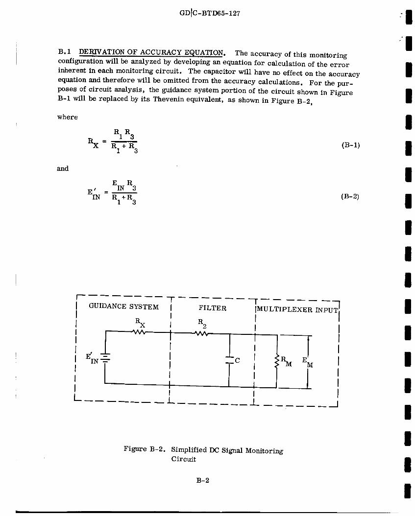
GD]C-BTD65-127 I
B. 1 DERIVATION OF ACCURACY EQUATION. The accuracy of this monitoring
configuration will be analyzed by developing an equation for calculation of the error
inherent in each monitoring circuit. The capacitor will have no effect on the accuracy
equation and therefore will be omitted from the accuracy calculations. For the pur-
poses of circuit analysis, the guidance system portion of the circuit shown in Figure
B-1 will be replaced by its Thevenin equivalent, as shown in Figure B-2,
where
(B-I)
I
I
I
i
I
and
E R
E ' IN 3I_°_;_ _-__ I
I 1" r[ GUIDANCE SYSTEM [
I iI Rx I
I II 1 I
- I
I II i
FILTER
R2
mC
[MULTIPLEXER INPUT
III, II
lS
I
I
II
I_ ..... 1 I
Figure B-2. Simplified DC Signal Monitoring
Circuit
B-2

Il
III
II
ll
lII
lI
l
Ill
I
GD[C-BTD65-127
The nominal voltage drop across multiplexer input resistor, RM, is
E I
IN RM(NoM)
EM(NOM) = RX(NOM) + R2(NOM )+ RM(NOM )(B-3)
Assuming a perfect conversion, the voltage at the output of the analog-to-digital con-
verter would be the voltage into the multiplexer amplifier multiplied by the gain of theamplifier.
(B-4)
Substituting the value of EM(NoM) (Equation B-3) into Equation B-4 yields
E g
IN Rf(NOM)
EDC(NOM ) = RX(NOM )+ R_NOM) + RM_NoM ) (B-5)
The maximum value of EDC can be found by assuming that the various resistors in
the circuit were all at their extreme tolerance values. The effect of a maximum ran-
dom conversion inaccuracy (0o 003 VDC) can also be included° Thus
E I
IN Rf(MAX)
= + + 0. 003 (B-6)EDC(MAX) RX(MIN ) + R2(MIN ) RM(MIN)
The end-to-end maximum measurement error, in percent, can now be defined as:
Error (percent) =
EDC(NOM)
100 (B-7)
Since the equation is linear, the error (in percent) found using maximum tolerance
values is equal to the value that would be found using minimum tolerance values. Sub-
stituting the results of Equations B-5 and B-6 into B-7:
B-3

GDIC-BTI)65-127
Error (percent) =
Rx( E_ _(M_) ) + o.o03MIN) + R2(MIN) + RM(MIN) '
X_NOM ) + R2(NOM ) + RM(NOM )
where
EIN R3(NOM)
E;N --RI(NOM )+ R3(NOM )
-1 100 (B-8)
(B-9)
RIINOM )R3_NOMI
RX(NOM) --RI(NOM )+ R3(NOM )
(B-10)
RI_ MIN) R3(MIN) (B-11)
RX(MIN ) = RI(MIN )+ R3(MIN )
Some guidance system circuits do not contain attenuation resistor R 3. For these cir-
cuits the same analysis as has been developed would apply, provided the following
substitutions were made in Equation B-8:
' (B-12)EIN -- EIN
RX(NoM ) = RI(NOM )(B-13)
RX(MIN ) = RI(MIN )(B-14)
B. 2 DERIVATION OF CAPACITOR VALUE EQUATION. The circuit shown in
Figure B-2 can be rearranged slightly to permit derivation of the required capacitor
value. The rearranged circuit is shown in Figure B-3.
The Thevenin's impedance of the circuit, seen at points A-A', is
R M (Rx + R 2)
RTHEV = RM+R x+R 2(B-15)
B-4
I
III
III
II
II
II
II
I
II
IL_
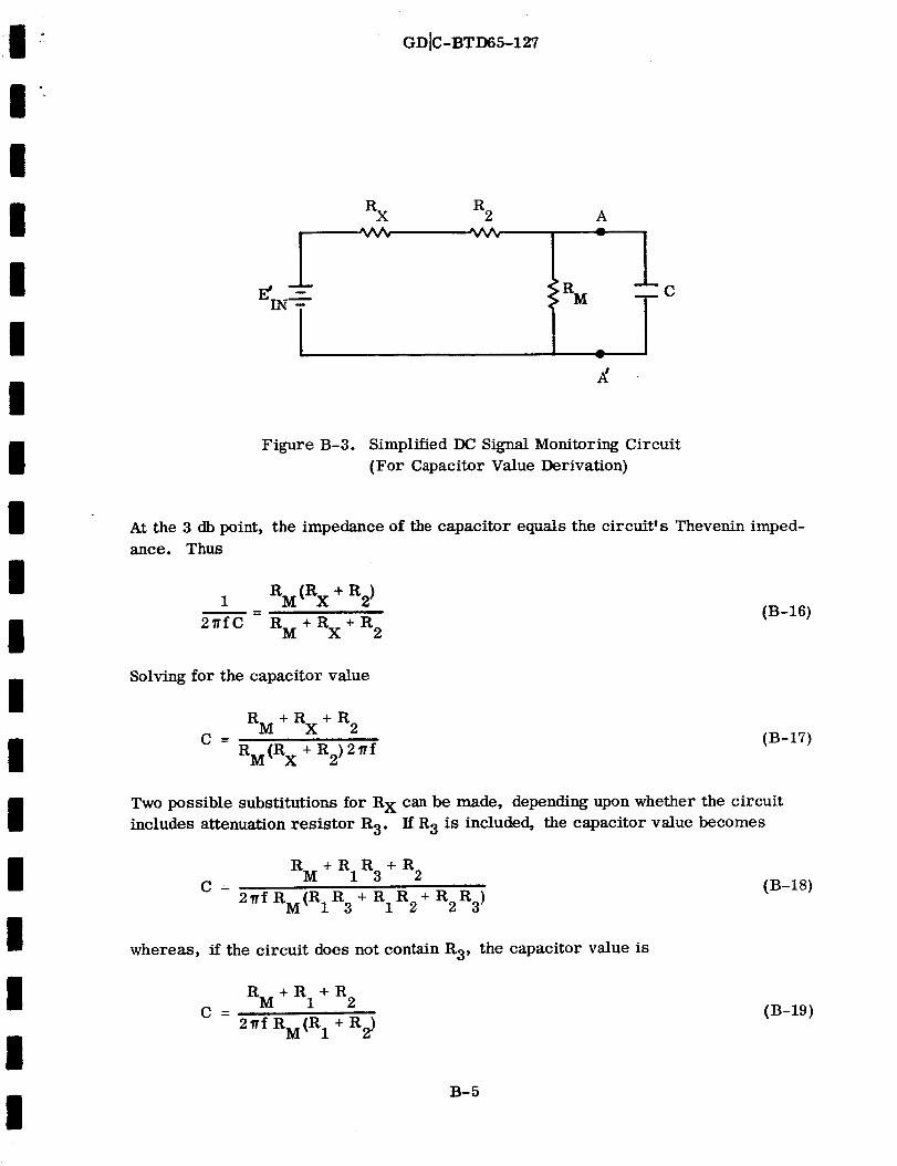
I
II
II
lI
II
IIl
I
lI
li
GD[C-BTD65-127
RX R 2 A
lTc
Figure B-3. Simplified DC Signal Monitoring Circuit
(For Capacitor Value Derivation)
At the 3 db point, the impedance of the capacitor equals the circuit's Thevenin imped-
ance. Thus
1 RM(Rx + R2}= (B-16)
2_'fC R M + R x + R 2
Solving for the capacitor value
R M + R x + R 2C = (B-17)
R M (Rx + R2) 2_ f
Two possible substitutions for R X can be made, depending upon whether the circuit
includes attenuation resistor R 3. If R3 is included, the capacitor value becomes
C
R M + R 1 R 3 + R 2
2yf RM(RIR 3 + RIR2 + R2R 3)(B-18)
whereas, if the circuit does not contain R 3, the capacitor value is
C ___
+RRM + R1 2
2 yf R M (R 1 + R 2)(B-19)
B-5