I ELEMENTS OF METRIC GEAR TECHNOLOGY - … · ELEMENTS OF METRIC GEAR TECHNOLOGY T-150 SECTION 17...
44
I R 1 2 3 4 5 6 7 8 9 10 11 12 13 T 14 15 A PHONE: 516.328.3300 • FAX: 516.326.8827 • WWW.SDP-SI.COM ELEMENTS OF METRIC GEAR TECHNOLOGY T-150 SECTION 17 STRENGTH AND DURABILITY OF GEARS The strength of gears is generally expressed in terms of bending strength and surface durability. These are independent criteria which can have differing criticalness, although usually both are important. Discussions in this section are based upon equations published in the literature of the Japanese Gear Manufacturer Association (JGMA). Reference is made to the following JGMA specifications: Specifications of JGMA: JGMA 401-01 Bending Strength Formula of Spur Gears and Helical Gears JGMA 402-01 Surface Durability Formula of Spur Gears and Helical Gears JGMA 403-01 Bending Strength Formula of Bevel Gears JGMA 404-01 Surface Durability Formula of Bevel Gears JGMA 405-01 The Strength Formula of Worm Gears Generally, bending strength and durability specifications are applied to spur and helical gears (including double helical and internal gears) used in industrial machines in the following range: Module: m 1.5 to 25 mm Pitch Diameter: d 25 to 3200 mm Tangential Speed: v less than 25 m/sec Rotating Speed: n less than 3600 rpm Conversion Formulas: Power, Torque and Force Gear strength and durability relate to the power and forces to be transmitted. Thus, the equations that relate tangential force at the pitch circle, F t (kgf), power, P (kw), and torque, T (kgf • m) are basic to the calculations. The relations are as follows: 102 P 1.95 x 10 6 P 2000 T F t = –––– = –––––––––– = ––––– (17-1) v d w n d w F t v 10 –6 P = –––– = –––– F t d w n (17-2) 102 1.95 F t d w 974 P T = –––– = ––––– (17-3) 2000 n where: v : Tangential Speed of Working Pitch Circle (m/sec) d w n v = ––––– 19100 d w : Working Pitch Diameter (mm) n : Rotating Speed (rpm) 17.1 Bending Strength Of Spur And Helical Gears In order to confirm an acceptable safe bending strength, it is necessary to analyze the applied tangential force at the working pitch circle, F t , vs. allowable force, F t lim . This is stated as: F t ≤ F t lim (17-4) Metric 0 10
Transcript of I ELEMENTS OF METRIC GEAR TECHNOLOGY - … · ELEMENTS OF METRIC GEAR TECHNOLOGY T-150 SECTION 17...
I
R
1
2
3
4
5
6
7
8
9
10
11
12
13
T
14
15
A
PHONE: 516.328.3300 • FAX: 516.326.8827 • WWW.SDP-SI.COM
ELEMENTS OF METRIC GEAR TECHNOLOGY
T-150
SECTION 17 STRENGTH AND DURABILITY OF GEARS
The strength of gears is generally expressed in terms of bending strength and surface durability. These are independent criteria which can have differing criticalness, although usually both are important. Discussions in this section are based upon equations published in the literature of the Japanese Gear Manufacturer Association (JGMA). Reference is made to the following JGMA specifications:
Specifications of JGMA:
JGMA 401-01 Bending Strength Formula of Spur Gears and Helical Gears JGMA 402-01 Surface Durability Formula of Spur Gears and Helical Gears JGMA 403-01 Bending Strength Formula of Bevel Gears JGMA 404-01 Surface Durability Formula of Bevel Gears JGMA 405-01 The Strength Formula of Worm Gears
Generally, bending strength and durability specifications are applied to spur and helical gears (including double helical and internal gears) used in industrial machines in the following range:
Module: m 1.5 to 25 mm Pitch Diameter: d 25 to 3200 mm Tangential Speed: v less than 25 m/sec Rotating Speed: n less than 3600 rpm Conversion Formulas: Power, Torque and Force
Gear strength and durability relate to the power and forces to be transmitted. Thus, the equations that relate tangential force at the pitch circle, Ft (kgf), power, P (kw), and torque, T (kgf • m) are basic to the calculations. The relations are as follows:
102 P 1.95 x 10⁶ P 2000 T Ft = –––– = –––––––––– = ––––– (17-1) v dw n dw
Ft v 10 –6
P = –––– = –––– Ft dwn (17-2) 102 1.95
Ft dw 974 P T = –––– = ––––– (17-3) 2000 n
where: v : Tangential Speed of Working Pitch Circle (m/sec) dwn v = ––––– 19100
dw : Working Pitch Diameter (mm) n : Rotating Speed (rpm)
17.1 Bending Strength Of Spur And Helical Gears
In order to confirm an acceptable safe bending strength, it is necessary to analyze the applied tangential force at the working pitch circle, Ft , vs. allowable force, Ft lim. This is stated as:
Ft ≤ Ft lim (17-4)
Metric
0 10
I
R
1
2
3
4
5
6
7
8
9
10
11
12
13
T
14
15
A
PHONE: 516.328.3300 • FAX: 516.326.8827 • WWW.SDP-SI.COM
ELEMENTS OF METRIC GEAR TECHNOLOGY
T-151
It should be noted that the greatest bending stress is at the root of the flank or base of the dedendum. Thus, it can be stated:
sF = actual stress on dedendum at root sF lim = allowable stress
Then Equation (17-4) becomes Equation (17-5)
sF ≤ sF lim (17-5)
Equation (17-6) presents the calculation of Ft lim:
mnb K LK FX 1 Ft lim = sF lim ––––––– (––––––) ––– (kgf) (17-6) YFYeYb KV KO SF
Equation (17-6) can be converted into stress by Equation (17-7):
YFYeYb KV KO sF = Ft –––––– (–––––) SF (kgf/mm2) (17-7) mnb KLKFX
17.1.1 Determination of Factors in the Bending Strength Equation
If the gears in a pair have different blank widths, let the wider one be bw and the narrower one be bs . And if: bw – bs ≤ mn, bw and bs can be put directly into Equation (17-6). bw – bs > mn, the wider one would be changed to bs + mn and the narrower one, bs , would be unchanged.
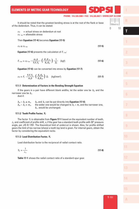
17.1.2 Tooth Profile Factor, YF
The factor YF is obtainable from Figure 17-1 based on the equivalent number of teeth, zv, and coefficient of profile shift, x, if the gear has a standard tooth profile with 20° pressure angle, per JIS B 1701. The theoretical limit of undercut is shown. Also, for profile shifted gears the limit of too narrow (sharp) a tooth top land is given. For internal gears, obtain the factor by considering the equivalent racks.
17.1.3 Load Distribution Factor, Ye
Load distribution factor is the reciprocal of radial contact ratio.
1 Ye = ––– (17-8) ea
Table 17-1 shows the radial contact ratio of a standard spur gear.
Metric
0 10
I
R
1
2
3
4
5
6
7
8
9
10
11
12
13
T
14
15
A
PHONE: 516.328.3300 • FAX: 516.326.8827 • WWW.SDP-SI.COM
ELEMENTS OF METRIC GEAR TECHNOLOGY
T-152
Fig. 17-1 Chart of Tooth Profile Factor, YF
Normal STD PressureAngle an = 20°Addendum ha = 1.00 mn
Dedendum hf = 1.25 mn
Corner Radius of Cutterg = 0.375 mn
Theoretical U
ndercut Lim
it
Narrow Tooth Top Limit
Toot
h Pr
ofile
Fac
tor,
Y F (
Form
Fac
tor)
3.8
3.7
3.6
3.5
3.4
3.3
3.2
3.1
3.0
2.9
2.8
2.7
2.6
2.5
2.4
2.3
2.2
2.1
2.0
1.9
1.8
3.5
3.4
3.3
3.2
3.1
3.0
2.9
2.8
2.7
2.6
2.5
2.4
2.3
2.2
2.1
2.0
1.9
1.810 11 12 13 14 15 16 17 18 19 20 25 30 35 40 45 50 60 80 100 200 400 ∞
X = –0.5
X = –0.4
X = –0.3
X = –0.2X = –0.1
X = 0X = 0.1
X = 0.2X = 0.3
X = 0.4X = 0.5X = 0.6
X = 0.7X = 0.8
X = 0.9X = 1.0
zEquivalent Spur Gear Number of Teeth zv = ––––– cos3 b
Metric
0 10

I
R
1
2
3
4
5
6
7
8
9
10
11
12
13
T
14
15
A
PHONE: 516.328.3300 • FAX: 516.326.8827 • WWW.SDP-SI.COM
ELEMENTS OF METRIC GEAR TECHNOLOGY
T-153
120
1.87
1
1.92
6
110
1.86
3
1.86
7
1.99
2
95 1.84
7
1.85
0
1.85
5
1.85
9
1.91
4
100
1.85
3
1.85
8
1.86
2
1.91
7
80 1.82
6
1.83
0
1.83
3
1.83
6
1.83
9
1.84
4
1.84
9
1.90
3
60 1.78
5
1.79
1
1.79
6
1.80
1
1.80
5
1.80
9
1.81
3
1.81
6
1.81
9
1.82
4
1.82
8
1.88
3
50 1.75
5
1.76
3
1.77
0
1.77
6
1.78
1
1.78
6
1.79
0
1.79
4
1.79
8
1.80
1
1.80
4
1.80
9
1.81
3
1.86
8
55 1.77
1
1.77
8
1.78
4
1.78
9
1.79
4
1.79
8
1.80
2
1.80
6
1.80
9
1.81
2
1.81
7
1.82
1
1.87
6
45 1.73
6
1.74
5
1.75
3
1.76
0
1.76
6
1.77
2
1.77
7
1.78
1
1.78
5
1.78
8
1.79
1
1.79
4
1.79
9
1.80
4
1.85
9
40 1.71
4
1.72
5
1.73
4
1.74
2
1.74
9
1.75
5
1.76
1
1.76
5
1.77
0
1.77
3
1.77
7
1.78
0
1.78
3
1.78
8
1.79
2
1.84
7
30 1.65
4
1.67
0
1.68
4
1.69
5
1.70
4
1.71
2
1.71
9
1.72
5
1.73
1
1.73
5
1.74
0
1.74
3
1.74
7
1.75
0
1.75
3
1.75
8
1.76
2
1.81
7
35 1.68
7
1.70
0
1.71
1
1.72
1
1.72
9
1.73
6
1.74
2
1.74
7
1.75
2
1.75
6
1.76
0
1.76
4
1.76
7
1.77
0
1.77
5
1.77
9
1.83
4
12
15
20
25
30
35
40
45
50
55
60
65
70
75
80
85
90
95
100
110
120
RACK
12 1.42
0
1.45
1
1.48
9
1.51
6
1.53
7
1.55
3
1.56
7
1.57
8
1.58
8
1.59
6
1.60
3
1.60
9
1.61
4
1.61
9
1.62
3
1.62
7
1.63
0
1.63
4
1.63
6
1.64
2
1.64
6
1.70
1
15 1.48
1
1.51
9
1.54
7
1.56
7
1.58
4
1.59
7
1.60
9
1.61
8
1.62
6
1.63
3
1.63
9
1.64
5
1.64
9
1.65
4
1.65
7
1.66
1
1.66
4
1.66
7
1.67
2
1.67
6
1.73
1
20 1.55
7
1.58
4
1.60
5
1.62
2
1.63
5
1.64
6
1.65
6
1.66
4
1.67
1
1.67
7
1.68
2
1.68
7
1.69
1
1.69
5
1.69
9
1.70
2
1.70
5
1.71
0
1.71
4
1.76
9
25 1.61
2
1.63
3
1.64
9
1.66
3
1.67
4
1.68
3
1.69
1
1.69
8
1.70
4
1.71
0
1.71
4
1.71
9
1.72
3
1.72
6
1.72
9
1.73
2
1.73
7
1.74
2
1.79
7
65 1.79
7
1.80
2
1.80
7
1.81
1
1.81
5
1.81
9
1.82
2
1.82
5
1.83
0
1.83
4
1.88
9
70 1.80
8
1.81
2
1.81
7
1.82
1
1.82
4
1.82
7
1.83
0
1.83
5
1.84
0
1.89
4
75 1.81
7
1.82
1
1.82
5
1.82
9
1.83
2
1.83
5
1.84
0
1.84
4
1.89
9
85 1.83
3
1.83
7
1.84
0
1.84
3
1.84
8
1.85
2
1.90
7
90 1.84
0
1.84
4
1.84
6
1.85
2
1.85
6
1.91
1
Tabl
e 17
-1 R
adia
l Con
tact
Rat
io o
f Sta
ndar
d Sp
ur G
ears
, ea (
a =
20°
)
17.1.4 Helix Angle Factor, Yb
Helix angle factor can be obtained from Equation (17-9). b When 0 ≤ b ≤ 30°, then Yb = 1 – ––– 120 (17-9) When b > 30°, then Yb = 0.75
Metric
0 10
I
R
1
2
3
4
5
6
7
8
9
10
11
12
13
T
14
15
A
PHONE: 516.328.3300 • FAX: 516.326.8827 • WWW.SDP-SI.COM
ELEMENTS OF METRIC GEAR TECHNOLOGY
1
2
3
4
5
6
1
2
3
4
––
––
––
––
––
1.0
1.0
1.0
1.1
1.2
––
1.0
1.1
1.2
1.3
1.4
1.5
1.0
1.05
1.15
1.3
1.4
1.5
1.0
1.1
1.2
1.4
1.5
1.1
1.2
1.3
1.5
1.2
1.3
1.5
1.3
1.5
T-154
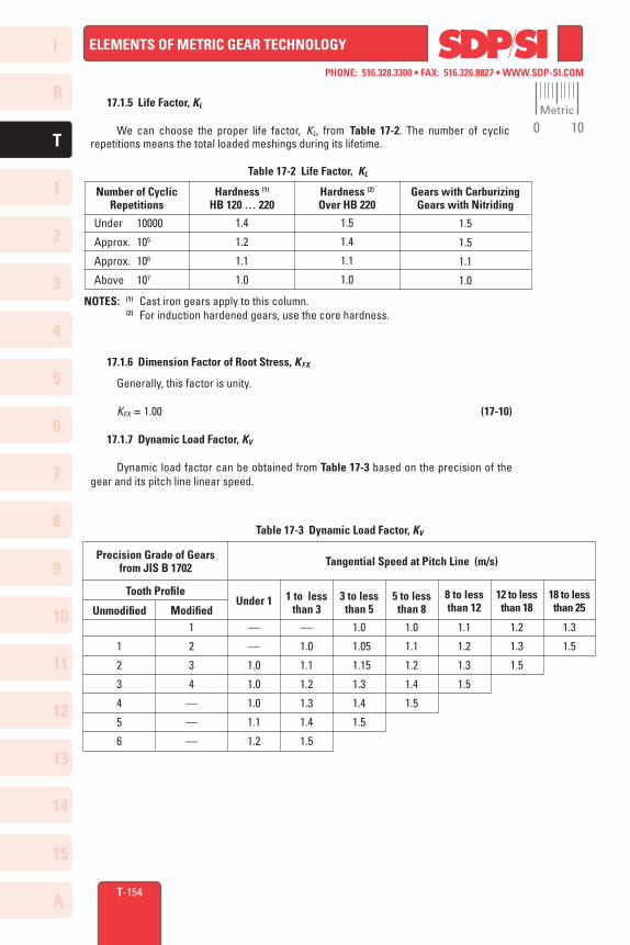
17.1.5 Life Factor, KL
We can choose the proper life factor, KL, from Table 17-2. The number of cyclic repetitions means the total loaded meshings during its lifetime.
17.1.6 Dimension Factor of Root Stress, KFX
Generally, this factor is unity.
KFX = 1.00 (17-10)
17.1.7 Dynamic Load Factor, KV
Dynamic load factor can be obtained from Table 17-3 based on the precision of the gear and its pitch line linear speed.
Table 17-3 Dynamic Load Factor, KV
Precision Grade of Gearsfrom JIS B 1702 Tangential Speed at Pitch Line (m/s)
Tooth Profile
Unmodified ModifiedUnder 1 1 to less
than 33 to less than 5
5 to less than 8
8 to less than 12
12 to less than 18
18 to less than 25
Table 17-2 Life Factor, KL
NOTES: (1) Cast iron gears apply to this column. (2) For induction hardened gears, use the core hardness.
Number of CyclicRepetitions
Hardness (1)
HB 120 … 220Gears with Carburizing
Gears with Nitriding
Under 10000
Approx. 105
Approx. 106
Above 107
1.4
1.2
1.1
1.0
1.5
1.4
1.1
1.0
1.5
1.5
1.1
1.0
Hardness (2)
Over HB 220
Metric
0 10

I
R
1
2
3
4
5
6
7
8
9
10
11
12
13
T
14
15
A
PHONE: 516.328.3300 • FAX: 516.326.8827 • WWW.SDP-SI.COM
ELEMENTS OF METRIC GEAR TECHNOLOGY
T-155
17.1.8 Overload Factor, KO
Overload factor, KO, is the quotient of actual tangential force divided by nominal tangential force, Ft. If tangential force is unknown, Table 17-4 provides guiding values.
Actual tangential force KO = ––––––––––––––––––––––––– (17-11) Nominal tangential force, Ft
Table 17-4 Overload Factor, KO
Uniform Load(Motor, Turbine,Hydraulic Motor)
Light Impact Load(Multicylinder Engine)
Medium Impact Load(Single Cylinder Engine)
1.0
1.25
1.5
1.25
1.5
1.75
1.75
2.0
2.25
Uniform Load Medium ImpactLoad
Heavy ImpactLoad
Impact from Load Side of MachineImpact from Prime Mover
17.1.9 Safety Factor for Bending Failure, SF
Safety factor, SF, is too complicated to be decided precisely. Usually, it is set to at least 1.2.
17.1.10 Allowable Bending Stress At Root, sF lim
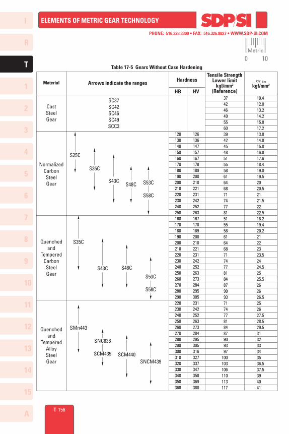
For the unidirectionally loaded gear, the allowable bending stresses at the root are shown in Tables 17-5 to 17-8. In these tables, the value of sF lim is the quotient of the tensile fatigue limit divided by the stress concentration factor 1.4. If the load is bidirectional, and both sides of the tooth are equally loaded, the value of allowable bending stress should be taken as 2/3 of the given value in the table. The core hardness means hardness at the center region of the root.
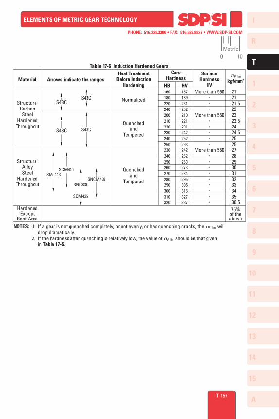
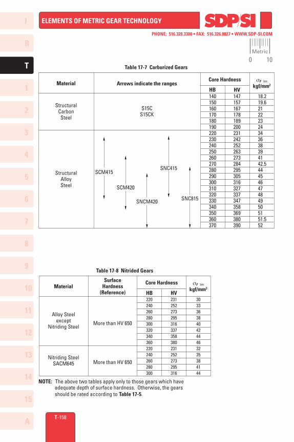
See Table 17-5 for sF lim of gears without case hardening. Table 17-6 gives sF lim of gears that are induction hardened; and Tables 17-7 and 17-8 give the values for carburized and nitrided gears, respectively. In Tables 17-8A and 17-8B, examples of calculations are given.
Metric
0 10
I
R
1
2
3
4
5
6
7
8
9
10
11
12
13
T
14
15
A
PHONE: 516.328.3300 • FAX: 516.326.8827 • WWW.SDP-SI.COM
ELEMENTS OF METRIC GEAR TECHNOLOGY
T-156
Table 17-5 Gears Without Case Hardening
HB HV 37 42 46 49 55 60 39 42 45 48 51 55 58 61 64 68 71 74 77 81 51 55 58 61 64 68 71 74 77 81 84 87 90 93 71 74 77 81 84 87 90 93 97100103106110113117
126136147157167178189200210221231242252263167178189200210221231242252263273284295305231242252263273284295305316327337347358369380
120130140150160170180190200210220230240250160170180190200210220230240250260270280290220230240250260270280290300310320330340350360
10.4 12.0 13.2 14.2 15.8 17.2 13.8 14.8 15.8 16.8 17.6 18.4 19.0 19.5
20 20.5
21 21.5
22 22.5 18.2 19.4 20.2
212223
23.524
24.525
25.52626
26.52526
27.5 28.5 29.5
3132333435
36.5 37.5
394041
S25C
S35C
SC37SC42SC46SC49SCC3
S43C
S48C
S53C
S58C
S35C
SMn443
S43C
SNC836
SCM435
S53C
S58C
SNCM439
S48C
SCM440
Tensile StrengthLower limit
kgf/mm2
(Reference)
sF limkgf/mm2Arrows indicate the rangesMaterial
CastSteelGear
NormalizedCarbonSteelGear
Quenchedand
TemperedCarbonSteelGear
Quenchedand
TemperedAlloySteelGear
Hardness
Metric
0 10
I
R
1
2
3
4
5
6
7
8
9
10
11
12
13
T
14
15
A
PHONE: 516.328.3300 • FAX: 516.326.8827 • WWW.SDP-SI.COM
ELEMENTS OF METRIC GEAR TECHNOLOGY
T-157
Table 17-6 Induction Hardened Gears
NOTES: 1. If a gear is not quenched completely, or not evenly, or has quenching cracks, the sF lim will drop dramatically. 2. If the hardness after quenching is relatively low, the value of sF lim should be that given in Table 17-5.
Surface Hardness
HVHB HV167189231252210221231242252263242252263273284295305316327337
160180220240200210220230240250230240250260270280290300310320
2121
21.52223
23.524
24.52525272829303132333435
36.5
More than 550"""
More than 550"""""
More than 550"""""""""
Heat TreatmentBefore Induction
Hardening
Core HardnessArrows indicate the rangesMaterial
StructuralCarbonSteel
HardenedThroughout
StructuralAlloySteel
HardenedThroughout
HardenedExcept
Root Area
sF lim
kgf/mm2
S48C
S48C
S43C
S43C
SMn443
SCM440
SNC836
SCM435
SNCM439
Normalized
Quenched and
Tempered
Quenchedand
Tempered
75%of theabove
Metric
0 10
I
R
1
2
3
4
5
6
7
8
9
10
11
12
13
T
14
15
A
PHONE: 516.328.3300 • FAX: 516.326.8827 • WWW.SDP-SI.COM
ELEMENTS OF METRIC GEAR TECHNOLOGY
T-158
SCM420
Table 17-8 Nitrided Gears
NOTE: The above two tables apply only to those gears which have adequate depth of surface hardness. Otherwise, the gears should be rated according to Table 17-5.
HB HV231252273295316337358380231252273295316
220240260280300320340360220240260280300
30333638404244463235384144
Core Hardness sF lim
kgf/mm2
Surface Hardness
(Reference)
More than HV 650
More than HV 650
Material
Alloy Steelexcept
Nitriding Steel
Nitriding SteelSACM645
Table 17-7 Carburized Gears
HB HV147157167178189200231242252263273284295305316327337347358369380390
140150160170180190220230240250260270280290300310320330340350360370
18.2 19.6
212223243436383941
42.54445464748495051
51.552
Core HardnessMaterial
StructuralCarbonSteel
StructuralAlloySteel
sF lim
kgf/mm2Arrows indicate the ranges
S15CS15CK
SCM415
SNC415
SNCM420
SNC815
Metric
0 10
I
R
1
2
3
4
5
6
7
8
9
10
11
12
13
T
14
15
A
PHONE: 516.328.3300 • FAX: 516.326.8827 • WWW.SDP-SI.COM
ELEMENTS OF METRIC GEAR TECHNOLOGY
1 2 3 4 5 6 7 8 9101112131415161718192021
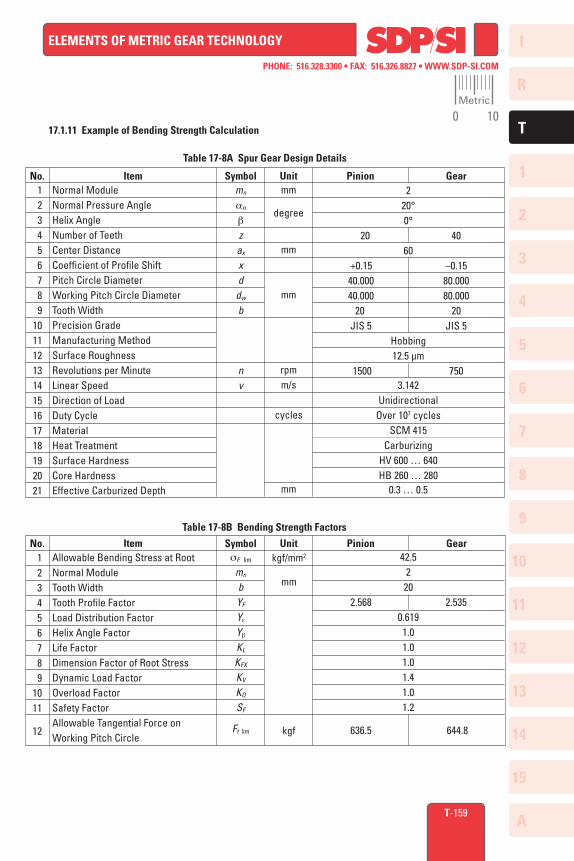
Normal ModuleNormal Pressure AngleHelix AngleNumber of TeethCenter DistanceCoefficient of Profile ShiftPitch Circle DiameterWorking Pitch Circle DiameterTooth WidthPrecision GradeManufacturing MethodSurface RoughnessRevolutions per MinuteLinear SpeedDirection of LoadDuty CycleMaterialHeat TreatmentSurface HardnessCore HardnessEffective Carburized Depth
T-159
17.1.11 Example of Bending Strength Calculation
Table 17-8B Bending Strength Factors
No. Item Symbol Unit Pinion Gear 1 2 3 4 5 6 7 8 91011
12
Allowable Bending Stress at RootNormal ModuleTooth WidthTooth Profile FactorLoad Distribution FactorHelix Angle FactorLife FactorDimension Factor of Root StressDynamic Load FactorOverload FactorSafety FactorAllowable Tangential Force on Working Pitch Circle
sF lim
mn
bYF
Ye
Yb
KL
KFX
KV
KO
SF
Ft lim
kgf/mm2
mm
kgf
42.5220
2.568 2.5350.6191.01.01.01.41.01.2
636.5 644.8
Table 17-8A Spur Gear Design Details
No. Item Symbol Unit Pinion Gearmn
an
b
zax
xd
dw
b
nv
mm
degree
mm
mm
rpmm/s
cycles
mm
220°0°
20 4060
+0.15 –0.15 40.000 80.000 40.000 80.000 20 20 JIS 5 JIS 5
Hobbing12.5 µm
1500 7503.142
UnidirectionalOver 107 cycles
SCM 415Carburizing
HV 600 … 640HB 260 … 280
0.3 … 0.5
Metric
0 10
I
R
1
2
3
4
5
6
7
8
9
10
11
12
13
T
14
15
A
PHONE: 516.328.3300 • FAX: 516.326.8827 • WWW.SDP-SI.COM
ELEMENTS OF METRIC GEAR TECHNOLOGY
17.2 Surface Strength Of Spur And Helical Gears
The following equations can be applied to both spur and helical gears, including double helical and internal gears, used in power transmission. The general range of application is:
Module: m 1.5 to 25 mm Pitch Circle: d 25 to 3200 mm Linear Speed: v less than 25 m/sec Rotating Speed: n less than 3600 rpm
17.2.1 Conversion Formulas
To rate gears, the required transmitted power and torques must be converted to tooth forces. The same conversion formulas, Equations (17-1), (17-2) and (17-3), of SECTION 17 (page T-150) are applicable to surface strength calculations.
17.2.2 Surface Strength Equations
As stated in SECTION 17.1, the tangential force, Ft , is not to exceed the allowable tangential force, Ft lim . The same is true for the allowable Hertz surface stress, sH lim . The Hertz stress sH is calculated from the tangential force, Ft. For an acceptable design, it must be less than the allowable Hertz stress sH lim . That is:
sH ≤ sH lim (17-12)
The tangential force, Ft lim, in kgf, at the standard pitch circle, can be calculated from Equation (17-13).
u KHLZL ZR ZV ZWKHX 1 1
Ft lim = sH lim2 d1bH ––– (–––––––––––––––)2
–––––––– –––– u ± 1 ZH ZM Ze Zb KH b KV KO SH
2
The Hertz stress sH (kgf/mm2) is calculated from Equation (17-14), where u is the ratio of numbers of teeth in the gear pair. Ft u ± 1 ZH ZM Ze Zb
sH = ––––– ––––– –––––––––––––––– KHbKV KO SH d1 bH u KH L ZL ZR ZV ZW KHX
The "+" symbol in Equations (17-13) and (17-14) applies to two external gears in mesh, whereas the "–" symbol is used for an internal gear and an external gear mesh. For the case of a rack and gear, the quantity u/(u ± 1) becomes 1.
17.2.3 Determination Of Factors In The Surface Strength Equations
17.2.3.A Effective Tooth Width, bH (mm)
The narrower face width of the meshed gear pair is assumed to be the effective width for surface strength. However, if there are tooth modifications, such as chamfer, tip relief or crowning, an appropriate amount should be subtracted to obtain the effective tooth width.
17.2.3.B Zone Factor, ZH
The zone factor is defined as: 2 cos bb cos awt 1
2 cos bb
ZH = –––––––––––––– = –––––– ––––––– (17-15) cos2 at sin awt
cos at tan awt
T-160
(17-13)
(17-14)
Metric
0 10

I
R
1
2
3
4
5
6
7
8
9
10
11
12
13
T
14
15
A
PHONE: 516.328.3300 • FAX: 516.326.8827 • WWW.SDP-SI.COM
ELEMENTS OF METRIC GEAR TECHNOLOGY
T-161
where: bb = tan–1 (tan b cos at)
The zone factors are presented in Figure 17-2 for tooth profiles per JIS B 1701, specified in terms of profile shift coefficients x1 and x2 , numbers of teeth z1 and z2 and helix angle b. The "+" symbol in Figure 17-2 applies to external gear meshes, whereas the "–" is used for internal gear and ex ternal gear meshes.
3.0
2.9
2.8
2.7
2.6
2.5
2.4
2.3
2.2
2.1
2.0
1.9
1.8
1.7
1.6
1.50° 5° 10° 15° 20° 25° 30° 35° 40° 45°
Helix Angle on Standard Pitch Cylinder b
Fig. 17-2 Zone Factor ZH
Zone
Fac
tor
Z H
(x1 ± x
2 )
––––––– = –0.02
(z1 ± z
2 )
– 0.0025
– 0.005
– 0.01
– 0.015
0+ 0.0025
+ 0.005
+ 0.01
+ 0.02+ 0.025
+ 0.05
+ 0.1+ 0.09
+ 0.08+ 0.07
+ 0.06
+ 0.015
+ 0.04
+ 0.03
Metric
0 10
I
R
1
2
3
4
5
6
7
8
9
10
11
12
13
T
14
15
A
PHONE: 516.328.3300 • FAX: 516.326.8827 • WWW.SDP-SI.COM
ELEMENTS OF METRIC GEAR TECHNOLOGY
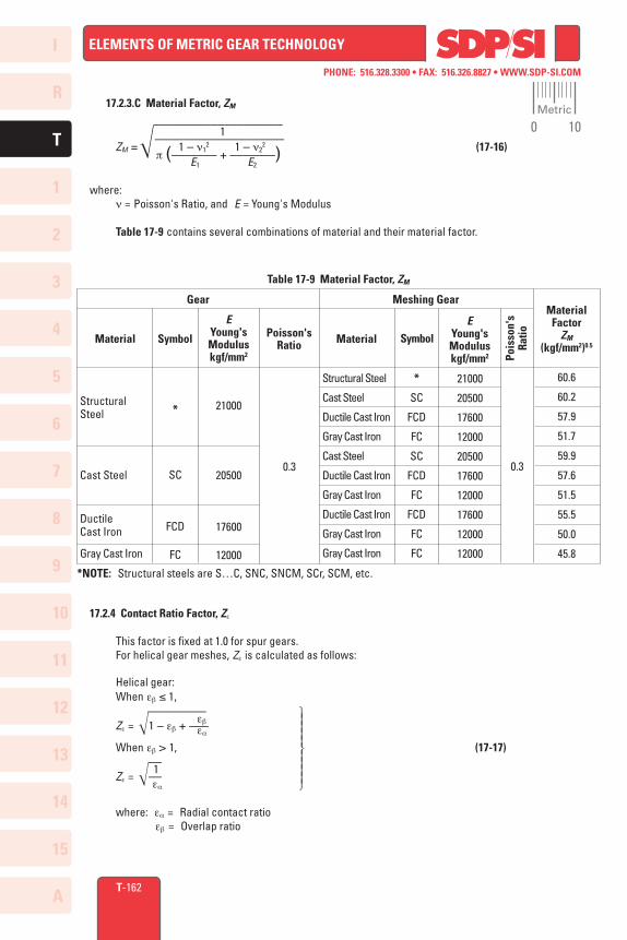
60.6
60.2
57.9
51.7
59.9
57.6
51.5
55.5
50.0
45.8
T-162
17.2.3.C Material Factor, ZM
–––––––––––––––––––– 1 –––––––––––––––––––– ZM = 1 – n1
2 1 – n22 (17-16)
p (––––––– + –––––––) E1 E2
where: n = Poisson's Ratio, and E = Young's Modulus
Table 17-9 contains several combinations of material and their material factor.
Table 17-9 Material Factor, ZM
Material Symbol Poisson'sRatio Material Symbol
Pois
son'
sRa
tio
Meshing GearGear
StructuralSteel
Cast Steel
Ductile Cast Iron
Gray Cast Iron
*
SC
FCD
FC
21000
20500
17600
12000
0.3
Structural Steel
Cast Steel
Ductile Cast Iron
Gray Cast Iron
Cast Steel
Ductile Cast Iron
Gray Cast Iron
Ductile Cast Iron
Gray Cast Iron
Gray Cast Iron
*
SC
FCD
FC
SC
FCD
FC
FCD
FC
FC
21000
20500
17600
12000
20500
17600
12000
17600
12000
12000
0.3
EYoung'sModuluskgf/mm2
EYoung'sModuluskgf/mm2
*NOTE: Structural steels are S…C, SNC, SNCM, SCr, SCM, etc.
MaterialFactor
ZM (kgf/mm2)0.5
17.2.4 Contact Ratio Factor, Ze
This factor is fixed at 1.0 for spur gears. For helical gear meshes, Ze is calculated as follows:
Helical gear: When eb ≤ 1, ––––––––– eb
Ze = 1 – eb + ––– ea
When eb > 1, (17-17) –– 1 Ze = –– ea
where: ea = Radial contact ratio
eb = Overlap ratio
Metric
0 10
I
R
1
2
3
4
5
6
7
8
9
10
11
12
13
T
14
15
A
PHONE: 516.328.3300 • FAX: 516.326.8827 • WWW.SDP-SI.COM
ELEMENTS OF METRIC GEAR TECHNOLOGY
T-163
17.2.5 Helix Angle Factor, Zb
This is a difficult parameter to evaluate. Therefore, it is assumed to be 1.0 unless better information is available.
Zb = 1.0 (17-18)
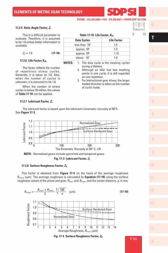
17.2.6 Life Factor, KHL
This factor reflects the number of repetit ious stress cycles. Generally, it is taken as 1.0. Also, when the number of cycles is unknown, it is assumed to be 1.0. When the number of stress cycles is below 10 million, the values of Table 17-10 can be applied.
17.2.7 Lubricant Factor, ZL
The lubricant factor is based upon the lubricant's kinematic viscosity at 50°C. See Figure 17-3.
Duty Cycles Life Factor1.51.3
1.151.0
less than 105
approx. 105
approx. 106
above 107
NOTES: 1. The duty cycle is the meshing cycles during a lifetime.
2. Although an idler has two meshing points in one cycle, it is still regarded as one repetition.
3. For bidirectional gear drives, the larger loaded direction is taken as the number of cyclic loads.
Table 17-10 Life Factor, KHL
1 2 3 4 5 6 7 8 9 10 11 12 13 14Average Roughness, Rmax m (µm)
Fig. 17-4 Surface Roughness Factor, ZR
1.1
1.0
0.9
0.8
0.7
Normalized Gear
Surface Hardened Gear
Roug
hnes
s Fa
ctor
Normalized Gear
Surface Hardened Gear
1.2
1.1
1.0
0.9
0.80 100 200 300
The Kinematic Viscosity at 50° C, cSt
Lubr
ican
t Fac
tor
NOTE: Normalized gears include quenched and tempered gearsFig. 17-3 Lubricant Factor, ZL
17.2.8 Surface Roughness Factor, ZR
This factor is obtained from Figure 17-4 on the basis of the average roughness Rmaxm (mm). The average roughness is calculated by Equation (17-19) using the surface roughness values of the pinion and gear, Rmax1 and Rmax2 , and the center distance, a, in mm. Rmax1 + Rmax2 100 Rmaxm = ––––––––––––
3–––– (mm) (17-19) 2 a
Metric
0 10
I
R
1
2
3
4
5
6
7
8
9
10
11
12
13
T
14
15
A
PHONE: 516.328.3300 • FAX: 516.326.8827 • WWW.SDP-SI.COM
ELEMENTS OF METRIC GEAR TECHNOLOGY
T-164
17.2.9 Sliding Speed Factor, ZV
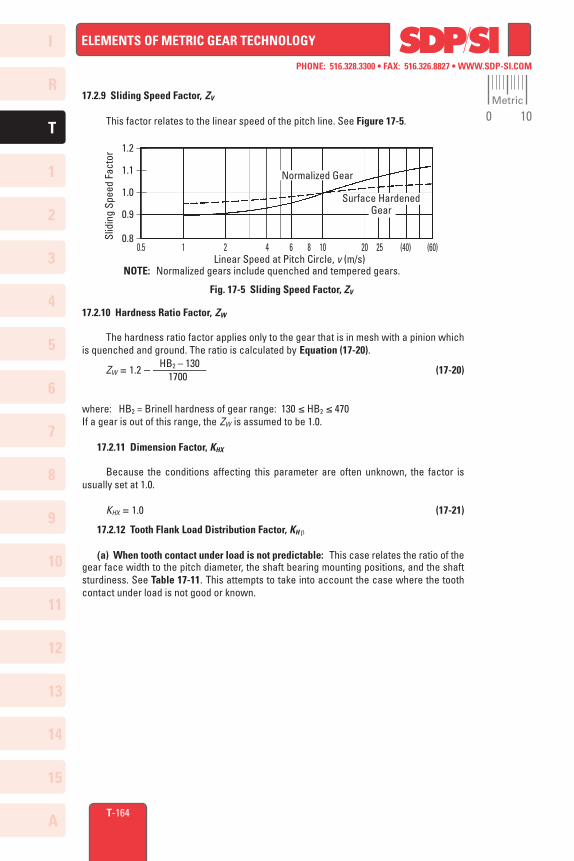
This factor relates to the linear speed of the pitch line. See Figure 17-5.
17.2.10 Hardness Ratio Factor, ZW
The hardness ratio factor applies only to the gear that is in mesh with a pinion which is quenched and ground. The ratio is calculated by Equation (17-20). HB2 – 130 ZW = 1.2 – ––––––––– (17-20) 1700
where: HB2 = Brinell hardness of gear range: 130 ≤ HB2 ≤ 470If a gear is out of this range, the ZW is assumed to be 1.0.
17.2.11 Dimension Factor, KHX
Because the conditions affecting this parameter are often unknown, the factor is usually set at 1.0.
KHX = 1.0 (17-21)
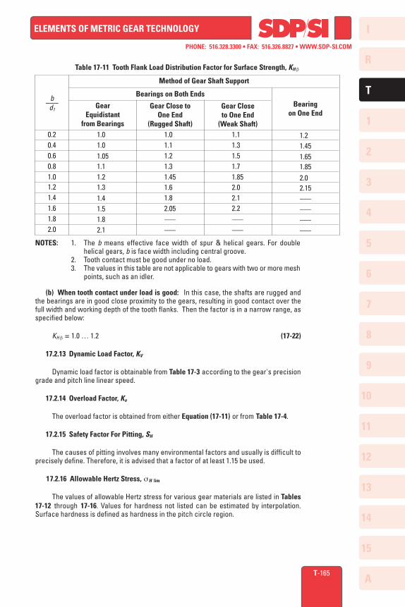
17.2.12 Tooth Flank Load Distribution Factor, KH b
(a) When tooth contact under load is not predictable: This case relates the ratio of the gear face width to the pitch diameter, the shaft bearing mounting positions, and the shaft sturdiness. See Table 17-11. This attempts to take into account the case where the tooth contact under load is not good or known.
NOTE: Normalized gears include quenched and tempered gears.
Fig. 17-5 Sliding Speed Factor, ZV
Normalized Gear
Surface Hardened Gear
1.2
1.1
1.0
0.9
0.8Slid
ing
Spee
d Fa
ctor
0.5 1 2 4 6 8 10 20 25 (40) (60)Linear Speed at Pitch Circle, v (m/s)
Metric
0 10
I
R
1
2
3
4
5
6
7
8
9
10
11
12
13
T
14
15
A
PHONE: 516.328.3300 • FAX: 516.326.8827 • WWW.SDP-SI.COM
ELEMENTS OF METRIC GEAR TECHNOLOGY
T-165
0.20.40.60.81.01.21.41.61.82.0
NOTES: 1. The b means effective face width of spur & helical gears. For double helical gears, b is face width including central groove.
2. Tooth contact must be good under no load. 3. The values in this table are not applicable to gears with two or more mesh
points, such as an idler.
Method of Gear Shaft Support
GearEquidistant
from Bearings
Gear Close toOne End
(Rugged Shaft)
Gear Closeto One End
(Weak Shaft)1.01.0
1.051.11.21.31.41.51.82.1
1.01.11.21.3
1.451.61.8
2.05 ––– –––
1.11.31.51.7
1.852.02.12.2
––– –––
1.2 1.45 1.65 1.852.0
2.15 ––– ––– ––– –––
Bearings on Both Endsb–––
d1Bearing
on One End
Table 17-11 Tooth Flank Load Distribution Factor for Surface Strength, KH b
(b) When tooth contact under load is good: In this case, the shafts are rugged and the bearings are in good close proximity to the gears, resulting in good contact over the full width and working depth of the tooth flanks. Then the factor is in a narrow range, as specified below:
KH b = 1.0 … 1.2 (17-22)
17.2.13 Dynamic Load Factor, KV
Dynamic load factor is obtainable from Table 17-3 according to the gear's precision grade and pitch line linear speed.
17.2.14 Overload Factor, Ko
The overload factor is obtained from either Equation (17-11) or from Table 17-4.
17.2.15 Safety Factor For Pitting, SH
The causes of pitting involves many environmental factors and usually is difficult to precisely define. Therefore, it is advised that a factor of at least 1.15 be used.
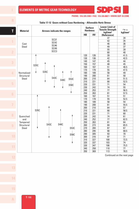
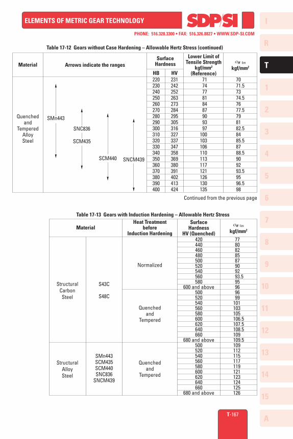
17.2.16 Allowable Hertz Stress, sH lim
The values of allowable Hertz stress for various gear materials are listed in Tables 17-12 through 17-16. Values for hardness not listed can be estimated by interpolation. Surface hardness is defined as hardness in the pitch circle region.
I
R
1
2
3
4
5
6
7
8
9
10
11
12
13
T
14
15
A
PHONE: 516.328.3300 • FAX: 516.326.8827 • WWW.SDP-SI.COM
ELEMENTS OF METRIC GEAR TECHNOLOGY
T-166
120130140150160170180190200210220230240250160170180190200210220230240250260270280290300310320330340350
Table 17-12 Gears without Case Hardening – Allowable Hertz Stress
HB HV 37 42 46 49 55 60 39 42 45 48 51 55 58 61 64 68 71 74 77 81 51 55 58 61 64 68 71 74 77 81 84 87 90 93 97100103106110113
126136147157167178189200210221231242253263167178189200210221231242252263273284295305316327337347358369
343536373940
41.5 42.5
4445
46.5 47.5
4950
51.5 52.5
5455
56.5 57.5
51 52.5
54 55.5
57 58.5
6061
62.564
65.567
68.57071
72.574
75.577
78.5
S25C
S35C
SC37SC42SC46SC49SCC3
S43C
S48C
S53C
S58C
S35C
S43C
S53C
S58C
S48C
Lower Limit ofTensile Strength
kgf/mm2
(Reference)
sH lim
kgf/mm2Arrows indicate the rangesMaterial
CastSteel
NormalizedStructural
Steel
Quenchedand
TemperedStructural
Steel
SurfaceHardness
Continued on the next page
I
R
1
2
3
4
5
6
7
8
9
10
11
12
13
T
14
15
A
PHONE: 516.328.3300 • FAX: 516.326.8827 • WWW.SDP-SI.COM
ELEMENTS OF METRIC GEAR TECHNOLOGY
71 74 77 81 84 87 90 93 97100103106110113117121126130135
T-167
Table 17-13 Gears with Induction Hardening – Allowable Hertz StressSurface
HardnessHV (Quenched)
Material
StructuralCarbonSteel
StructuralAlloySteel
sH lim
kgf/mm2
S43C
S48C
SMn443SCM435SCM440SNC836
SNCM439
Normalized
Quenched and
Tempered
Quenchedand
Tempered
420440460480500520540560580
600 and above500520540560580600620640660
680 and above500520540560580600620640660
680 and above
Heat Treatmentbefore
Induction Hardening 77 80 82 85 87 90 92
93.5 95 96 96 99 101 103 105
106.5 107.5 108.5
109 109.5
109 112 115 117 119 121 123 124 125 126
220230240250260270280290300310320330340350360370380390400
SNC836
SCM435
Table 17-12 Gears without Case Hardening – Allowable Hertz Stress (continued)
SMn443
SCM440
SNCM439
HB HV231242252263273284295305316327337347358369380391402413424
70 71.5
73 74.5
76 77.5
7981
82.584
85.587
88.59092
93.595
96.598
Lower Limit ofTensile Strength
kgf/mm2
(Reference)
sH lim
kgf/mm2Arrows indicate the rangesMaterial
Quenchedand
TemperedAlloySteel
SurfaceHardness
Continued from the previous page
I
R
1
2
3
4
5
6
7
8
9
10
11
12
13
T
14
15
A
PHONE: 516.328.3300 • FAX: 516.326.8827 • WWW.SDP-SI.COM
ELEMENTS OF METRIC GEAR TECHNOLOGY
T-168
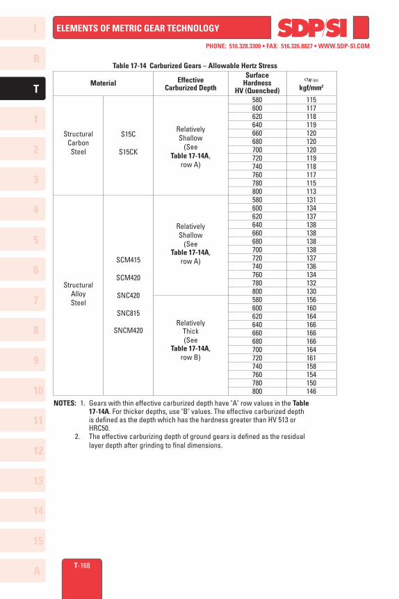
Table 17-14 Carburized Gears – Allowable Hertz Stress
NOTES: 1. Gears with thin effective carburized depth have "A" row values in the Table 17-14A. For thicker depths, use "B" values. The effective carburized depth is defined as the depth which has the hardness greater than HV 513 or HRC50. 2. The effective carburizing depth of ground gears is defined as the residual layer depth after grinding to final dimensions.
SurfaceHardness
HV (Quenched)Material
StructuralCarbonSteel
StructuralAlloySteel
EffectiveCarburized Depth
sH lim
kgf/mm2
580600620640660680700720740760780800580600620640660680700720740760780800580600620640660680700720740760780800
115117118119120120120119118117115113131134137138138138138137136134132130156160164166166166164161158154150146
S15C
S15CK
SCM415
SCM420
SNC420
SNC815
SNCM420
RelativelyShallow
(See Table 17-14A,
row A)
RelativelyShallow
(See Table 17-14A,
row A)
RelativelyThick(See
Table 17-14A,row B)
I
R
1
2
3
4
5
6
7
8
9
10
11
12
13
T
14
15
A
PHONE: 516.328.3300 • FAX: 516.326.8827 • WWW.SDP-SI.COM
ELEMENTS OF METRIC GEAR TECHNOLOGY
T-169
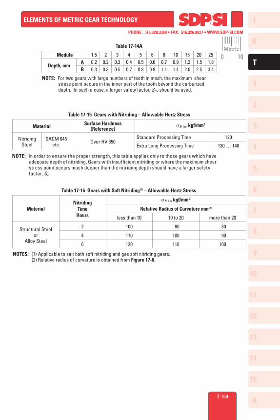
Table 17-14A
NOTE: For two gears with large numbers of teeth in mesh, the maximum shear stress point occurs in the inner part of the tooth beyond the carburized depth. In such a case, a larger safety factor, SH , should be used.
Depth, mm
Module 1.50.20.3
AB
20.20.3
30.30.5
40.40.7
50.50.8
60.60.9
80.71.1
100.91.4
151.22.0
201.52.5
251.83.4
Table 17-15 Gears with Nitriding – Allowable Hertz Stress
NOTE: In order to ensure the proper strength, this table applies only to those gears which have adequate depth of nitriding. Gears with insufficient nitriding or where the maximum shear stress point occurs much deeper than the nitriding depth should have a larger safety factor, SH .
Surface Hardness(Reference)Material sH lim kgf/mm2
Standard Processing Time
Extra Long Processing Time
120
130 … 140Over HV 650SACM 645
etc.Nitriding
Steel
Table 17-16 Gears with Soft Nitriding(1) – Allowable Hertz Stress
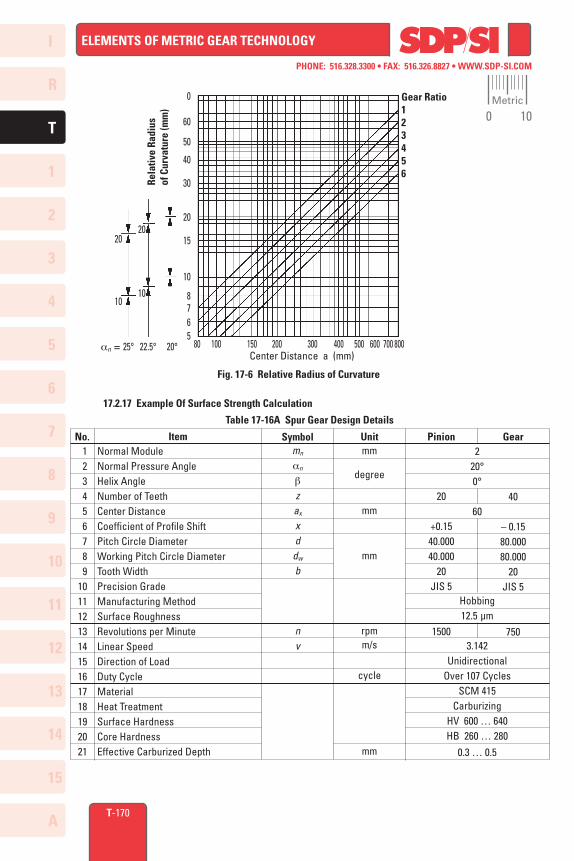
NOTES: (1) Applicable to salt bath soft nitriding and gas soft nitriding gears. (2) Relative radius of curvature is obtained from Figure 17-6.
Material
Structural Steel or
Alloy Steel
Nitriding TimeHours
sH lim kgf/mm 2
Relative Radius of Curvature mm(2)
2
4
6
less than 10
100
110
120
10 to 20
90
100
110
more than 20
80
90
100
Metric
0 10
I
R
1
2
3
4
5
6
7
8
9
10
11
12
13
T
14
15
A
PHONE: 516.328.3300 • FAX: 516.326.8827 • WWW.SDP-SI.COM
ELEMENTS OF METRIC GEAR TECHNOLOGY
Normal ModuleNormal Pressure AngleHelix AngleNumber of TeethCenter DistanceCoefficient of Profile ShiftPitch Circle DiameterWorking Pitch Circle DiameterTooth WidthPrecision GradeManufacturing MethodSurface RoughnessRevolutions per MinuteLinear SpeedDirection of LoadDuty CycleMaterialHeat TreatmentSurface HardnessCore HardnessEffective Carburized Depth
T-170
Fig. 17-6 Relative Radius of Curvature
Gear Ratio123456
Rela
tive
Radi
usof
Cur
vatu
re (m
m)
0
60
50
40
30
20
15
10
8765
an = 25° 22.5° 20°
20
10
20
10
80 100 150 200 300 400 500 600 700 800Center Distance a (mm)
20
+0.1540.00040.000
20JIS 5
1500
17.2.17 Example Of Surface Strength Calculation
Table 17-16A Spur Gear Design Details
No. Item Symbol Unit Pinion Gear 1 2 3 4 5 6 7 8 9101112131415161718192021
mn
an
b
zax
xd
dw
b
nv
mm
degree
mm
mm
rpmm/s
cycle
mm
220°0° 60
Hobbing12.5 µm
3.142
UnidirectionalOver 107 Cycles
SCM 415Carburizing
HV 600 … 640HB 260 … 280
0.3 … 0.5
40
– 0.1580.00080.000
20JIS 5
750
Metric
0 10
I
R
1
2
3
4
5
6
7
8
9
10
11
12
13
T
14
15
A
PHONE: 516.328.3300 • FAX: 516.326.8827 • WWW.SDP-SI.COM
ELEMENTS OF METRIC GEAR TECHNOLOGY
kgf/mm2
mm
(kgf/mm2)0.5
kgf
16440202
2.49560.61.01.01.01.00.900.971.01.0
1.0251.41.01.15
251.9
1 2 3 4 5 6 7 8 9
1011
121314151617
18
19
T-171
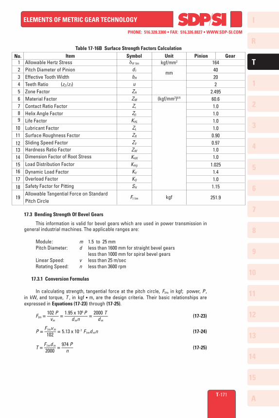
Table 17-16B Surface Strength Factors Calculation
No. Item Symbol Unit Pinion GearAllowable Hertz StressPitch Diameter of PinionEffective Tooth WidthTeeth Ratio (z2 /z1)Zone FactorMaterial FactorContact Ratio FactorHelix Angle FactorLife FactorLubricant FactorSurface Roughness FactorSliding Speed FactorHardness Ratio FactorDimension Factor of Root StressLoad Distribution FactorDynamic Load FactorOverload FactorSafety Factor for PittingAllowable Tangential Force on Standard Pitch Circle
dH lim
d1
bH
uZH
ZM
Ze
Zb
KHL
ZL
ZR
ZV
ZW
KHX
KH b
KV
KO
SH
Ft lim
17.3 Bending Strength Of Bevel Gears
This information is valid for bevel gears which are used in power transmission in general industrial machines. The applicable ranges are:
Module: m 1.5 to 25 mm Pitch Diameter: d less than 1600 mm for straight bevel gears less than 1000 mm for spiral bevel gears Linear Speed: v less than 25 m/sec Rotating Speed: n less than 3600 rpm
17.3.1 Conversion Formulas
In calculating strength, tangential force at the pitch circle, Ftm, in kgf; power, P , in kW, and torque, T , in kgf • m, are the design criteria. Their basic relationships are expressed in Equations (17-23) through (17-25).
102 P 1.95 x 10⁶ P 2000 T Ftm = –––– = –––––––– = ––––– (17-23) vm dmn dm
Ftmvm P = –––– = 5.13 x 10⁻⁷ Ftmdmn (17-24) 102
Ftmdm 974 P T = –––– = –––– (17-25) 2000 n
I
R
1
2
3
4
5
6
7
8
9
10
11
12
13
T
14
15
A
PHONE: 516.328.3300 • FAX: 516.326.8827 • WWW.SDP-SI.COM
ELEMENTS OF METRIC GEAR TECHNOLOGY
T-172
17.3.2 Bending Strength Equations
The tangential force, Ftm , acting at the central pitch circle should be equal to or less than the allowable tangential force, Ftm lim, which is based upon the allowable bending stress sF lim. That is:
Ftm ≤ Ftm lim (17-26)
The bending stress at the root, sF , which is derived from Ftm should be equal to or less than the allowable bending stress sF lim.
sF ≤ sF lim (17-27)
The tangential force at the central pitch circle, Ftm lim (kgf), is obtained from Equation (17-28). Ra – 0.5 b 1 KLKFX 1 Ftm lim = 0.85 cos bm sF lim mb –––––––– ––––––– (–––––––) ––– (17-28) Ra YFYeYbYC KMKV KO KR
where: bm : Central spiral angle (degrees) m : Radial module (mm) Ra : Cone distance (mm)
And the bending strength sF (kgf/mm2) at the root of tooth is calculated from Equation (17-29).
YFYeYbYC Ra KMKV KO sF = Ftm ––––––––––– –––––––– (–––––––)KR (17-29) 0.85 cos bm mb Ra – 0.5 b KLKFX
17.3.3 Determination of Factors in Bending Strength Equations
17.3.3.A Tooth Width, b (mm)
The term b is defined as the tooth width on the pitch cone, analogous to face width of spur or helical gears. For the meshed pair, the narrower one is used for strength calculations.
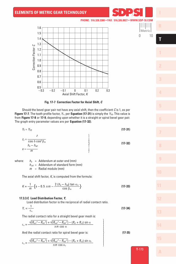
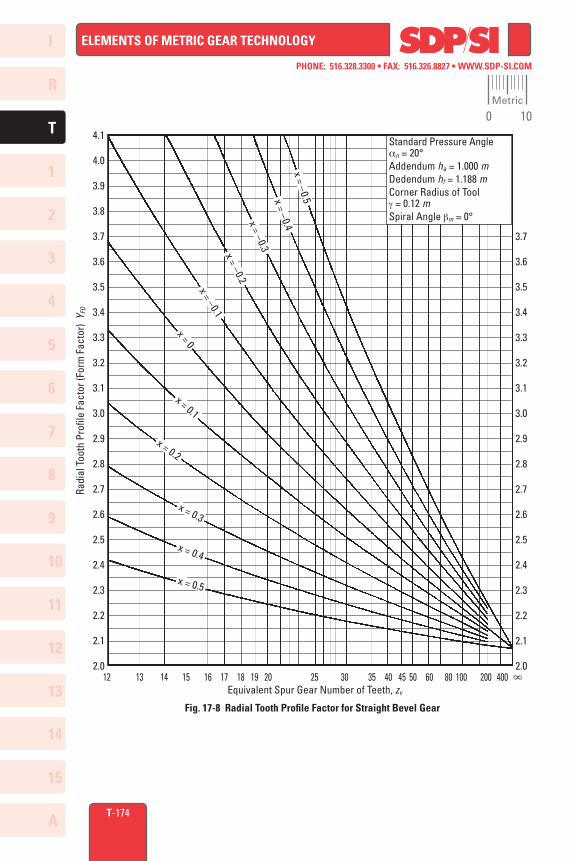
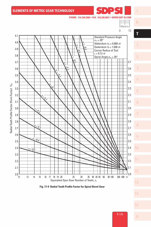
17.3.3.B Tooth Profile Factor, YF
The tooth profile factor is a function of profile shift, in both the radial and axial directions.Using the equivalent (virtual) spur gear tooth number, the first step is to determine the radial tooth profile factor, YFO, from Figure 17-8 for straight bevel gears and Figure 17-9 for spiral bevel gears. Next, determine the axial shift factor, K, with Equation (17-33) from which the axial shift correction factor, C, can be obtained using Figure 17-7. Finally, calculate YF by Equation (17-30).
YF = CYFO (17-30)
Metric
0 10
I
R
1
2
3
4
5
6
7
8
9
10
11
12
13
T
14
15
A
PHONE: 516.328.3300 • FAX: 516.326.8827 • WWW.SDP-SI.COM
ELEMENTS OF METRIC GEAR TECHNOLOGY
T-173
Fig. 17-7 Correction Factor for Axial Shift, C
1.6
1.5
1.4
1.3
1.2
1.1
1.0
0.9
0.8
0.7
0.6
0.5– 0.3 – 0.2 – 0.1 0 0.1 0.2 0.3
Axial Shift Factor, K
Corr
ectio
n Fa
ctor
C
Should the bevel gear pair not have any axial shift, then the coefficient C is 1, as per Figure 17-7. The tooth profile factor, YF , per Equation (17-31) is simply the YFO. This value is from Figure 17-8 or 17-9, depending upon whether it is a straight or spiral bevel gear pair. The graph entry parameter values are per Equation (17-32).
YF = YFO (17-31)
z zv = –––––––––– cos d cos3 bm (17-32) ha – ha0 x = –––––– m
where: ha = Addendum at outer end (mm) ha0 = Addendum of standard form (mm) m = Radial module (mm)
The axial shift factor, K, is computed from the formula:
1 2 (ha – ha0) tan an K = ––– {s – 0.5 pm – ––––––––––––––} (17-33) m cos bm
17.3.3.C Load Distribution Factor, Ye
Load distribution factor is the reciprocal of radial contact ratio. 1 Ye = ––– (17-34) ea
The radial contact ratio for a straight bevel gear mesh is: √(Rva1
2 – Rvb1 2) + √(Rva2
2 – Rvb2 2 ) – (Rv1 + Rv2) sin a
ea = –––––––––––––––––––––––––––––––––––––––– pm cos a And the radial contact ratio for spiral bevel gear is: (17-35) √(Rva1
2 – Rvb1 2) + √(Rva2
2 – Rvb2 2 ) – (Rv1 + Rv2) sin at
ea = –––––––––––––––––––––––––––––––––––––––– pm cos a t
Metric
0 10
I
R
1
2
3
4
5
6
7
8
9
10
11
12
13
T
14
15
A
PHONE: 516.328.3300 • FAX: 516.326.8827 • WWW.SDP-SI.COM
ELEMENTS OF METRIC GEAR TECHNOLOGY
T-174
Fig. 17-8 Radial Tooth Profile Factor for Straight Bevel Gear
4.1
4.0
3.9
3.8
3.7
3.6
3.5
3.4
3.3
3.2
3.1
3.0
2.9
2.8
2.7
2.6
2.5
2.4
2.3
2.2
2.1
2.0
3.7
3.6
3.5
3.4
3.3
3.2
3.1
3.0
2.9
2.8
2.7
2.6
2.5
2.4
2.3
2.2
2.1
2.012 13 14 15 16 17 18 19 20 25 30 35 40 45 50 60 80 100 200 400 ∞
Equivalent Spur Gear Number of Teeth, zv
Radi
al T
ooth
Pro
file
Fact
or (F
orm
Fac
tor)
YFO
Standard Pressure Anglean = 20°Addendum ha = 1.000 mDedendum hf = 1.188 mCorner Radius of Toolg = 0.12 mSpiral Angle bm = 0°
x = –0.2
x = 0.5
x = 0.4
x = 0.3
x = 0.2
x = 0.1
x = 0x = –0.1
x = –0.3x = –0.4
x = –0.5
Metric
0 10
I
R
1
2
3
4
5
6
7
8
9
10
11
12
13
T
14
15
A
PHONE: 516.328.3300 • FAX: 516.326.8827 • WWW.SDP-SI.COM
ELEMENTS OF METRIC GEAR TECHNOLOGY
T-175
4.1
4.0
3.9
3.8
3.7
3.6
3.5
3.4
3.3
3.2
3.1
3.0
2.9
2.8
2.7
2.6
2.5
2.4
2.3
2.2
2.1
2.012 13 14 15 16 17 18 19 20 25 30 35 40 45 50 60 80 100 200 400 ∞
Equivalent Spur Gear Number of Teeth, zv
Radi
al T
ooth
Pro
file
Fact
or (F
orm
Fac
tor)
YFO
3.7
3.6
3.5
3.4
3.3
3.2
3.1
3.0
2.9
2.8
2.7
2.6
2.5
2.4
2.3
2.2
2.1
2.0
x = –0.5
x = –0.4
x = –0.3x = –0.2x = –0.1
x = 0
x = 0.1
x = 0.5
x = 0.4
x = 0.3
x = 0.2
Fig. 17-9 Radial Tooth Profile Factor for Spiral Bevel Gear
Standard Pressure Anglean = 20°Addendum ha = 0.850 mDedendum hf = 1.038 mCorner Radius of Toolg = 0.12 mSpiral Angle bm = 35°
Metric
0 10
I
R
1
2
3
4
5
6
7
8
9
10
11
12
13
T
14
15
A
PHONE: 516.328.3300 • FAX: 516.326.8827 • WWW.SDP-SI.COM
ELEMENTS OF METRIC GEAR TECHNOLOGY
T-176
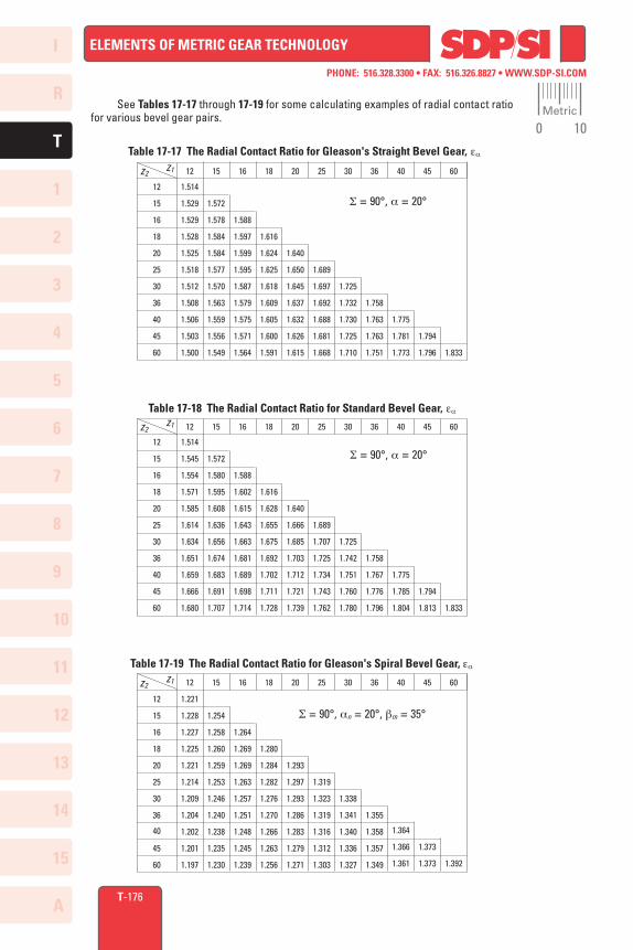
See Tables 17-17 through 17-19 for some calculating examples of radial contact ratio for various bevel gear pairs.
Table 17-17 The Radial Contact Ratio for Gleason's Straight Bevel Gear, ea
20
1.640
1.650
1.645
1.637
1.632
1.626
1.615
12
15
16
18
20
25
30
36
40
45
60
12
1.514
1.529
1.529
1.528
1.525
1.518
1.512
1.508
1.506
1.503
1.500
15
1.572
1.578
1.584
1.584
1.577
1.570
1.563
1.559
1.556
1.549
16
1.588
1.597
1.599
1.595
1.587
1.579
1.575
1.571
1.564
18
1.616
1.624
1.625
1.618
1.609
1.605
1.600
1.591
25
1.689
1.697
1.692
1.688
1.681
1.668
30
1.725
1.732
1.730
1.725
1.710
36
1.758
1.763
1.763
1.751
40
1.775
1.781
1.773
45
1.794
1.796
60
1.833
z2
S = 90°, a = 20°
z1
60
1.833
Table 17-18 The Radial Contact Ratio for Standard Bevel Gear, ea
12
15
16
18
20
25
30
36
40
45
60
12
1.514
1.545
1.554
1.571
1.585
1.614
1.634
1.651
1.659
1.666
1.680
15
1.572
1.580
1.595
1.608
1.636
1.656
1.674
1.683
1.691
1.707
16
1.588
1.602
1.615
1.643
1.663
1.681
1.689
1.698
1.714
18
1.616
1.628
1.655
1.675
1.692
1.702
1.711
1.728
25
1.689
1.707
1.725
1.734
1.743
1.762
30
1.725
1.742
1.751
1.760
1.780
36
1.758
1.767
1.776
1.796
40
1.775
1.785
1.804
45
1.794
1.813
S = 90°, a = 20°
20
1.640
1.666
1.685
1.703
1.712
1.721
1.739
z2z1
20
1.293
1.297
1.293
1.286
1.283
1.279
1.271
12
15
16
18
20
25
30
36
40
45
60
12
1.221
1.228
1.227
1.225
1.221
1.214
1.209
1.204
1.202
1.201
1.197
15
1.254
1.258
1.260
1.259
1.253
1.246
1.240
1.238
1.235
1.230
16
1.264
1.269
1.269
1.263
1.257
1.251
1.248
1.245
1.239
18
1.280
1.284
1.282
1.276
1.270
1.266
1.263
1.256
25
1.319
1.323
1.319
1.316
1.312
1.303
30
1.338
1.341
1.340
1.336
1.327
36
1.355
1.358
1.357
1.349
40
1.364
1.366
1.361
45
1.373
1.373
60
1.392
S = 90°, an = 20°, bm = 35°
Table 17-19 The Radial Contact Ratio for Gleason's Spiral Bevel Gear, ea
z2z1
Metric
0 10
I
R
1
2
3
4
5
6
7
8
9
10
11
12
13
T
14
15
A
PHONE: 516.328.3300 • FAX: 516.326.8827 • WWW.SDP-SI.COM
ELEMENTS OF METRIC GEAR TECHNOLOGY
T-177
17.3.3.D Spiral Angle Factor, Yb
The spiral angle factor is a function of the spiral angle. The value is arbitrarily set by the following conditions: bm When 0 ≤ bm ≤ 30°, Yb = 1 – –––– 120 (17-36) When bm ≥ 30°, Yb = 0.75
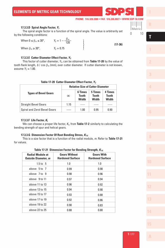
17.3.3.E Cutter Diameter Effect Factor, YC
This factor of cutter diameter, YC, can be obtained from Table 17-20 by the value of tooth flank length, b / cos bm (mm), over cutter diameter. If cutter diameter is not known, assume YC = 1.00.
17.3.3.F Life Factor, KL
We can choose a proper life factor, KL, from Table 17-2 similarly to calculating the bending strength of spur and helical gears.
17.3.3.G Dimension Factor Of Root Bending Stress, KFX
This is a size factor that is a function of the radial module, m. Refer to Table 17-21 for values.
Table 17-20 Cutter Diameter Effect Factor, YC
Relative Size of Cutter Diameter
5 Times ToothWidth
4 Times ToothWidth
Types of Bevel Gears
Straight Bevel Gears
Spiral and Zerol Bevel Gears
6 Times ToothWidth
∞
1.15
–––
–––
1.00
–––
0.95
–––
0.90
Table 17-21 Dimension Factor for Bending Strength, KFX
Radial Module atOutside Diameter, m
Gears WithoutHardened Surface
Gears WithHardened Surface
1.5 to 5
above 5 to 7
above 7 to 9
above 9 to 11
above 11 to 13
above 13 to 15
above 15 to 17
above 17 to 19
above 19 to 22
above 22 to 25
1.0
0.99
0.98
0.97
0.96
0.94
0.93
0.92
0.90
0.88
1.0
0.98
0.96
0.94
0.92
0.90
0.88
0.86
0.83
0.80
Metric
0 10
I
R
1
2
3
4
5
6
7
8
9
10
11
12
13
T
14
15
A
PHONE: 516.328.3300 • FAX: 516.326.8827 • WWW.SDP-SI.COM
ELEMENTS OF METRIC GEAR TECHNOLOGY
T-178
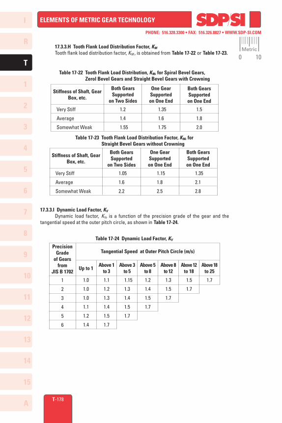
17.3.3.H Tooth Flank Load Distribution Factor, KM
Tooth flank load distribution factor, KM , is obtained from Table 17-22 or Table 17-23.
17.3.3.I Dynamic Load Factor, KV
Dynamic load factor, KV, is a function of the precision grade of the gear and the tangential speed at the outer pitch circle, as shown in Table 17-24.
Table 17-23 Tooth Flank Load Distribution Factor, KM, for Straight Bevel Gears without Crowning
Stiffness of Shaft, Gear Box, etc.
Both GearsSupported
on Two Sides
One GearSupportedon One End
Both GearsSupportedon One End
Very Stiff
Average
Somewhat Weak
1.05
1.6
2.2
1.15
1.8
2.5
1.35
2.1
2.8
Table 17-22 Tooth Flank Load Distribution, KM, for Spiral Bevel Gears, Zerol Bevel Gears and Straight Bevel Gears with Crowning
Stiffness of Shaft, Gear Box, etc.
Both GearsSupported
on Two Sides
One GearSupportedon One End
Both GearsSupportedon One End
Very Stiff
Average
Somewhat Weak
1.2
1.4
1.55
1.35
1.6
1.75
1.5
1.8
2.0
Table 17-24 Dynamic Load Factor, KV
1
2
3
4
5
6
1.0
1.0
1.0
1.1
1.2
1.4
1.1
1.2
1.3
1.4
1.5
1.7
1.15
1.3
1.4
1.5
1.7
1.2
1.4
1.5
1.7
1.3
1.5
1.7
1.5
1.7
1.7
Tangential Speed at Outer Pitch Circle (m/s)
Above 1 to 3
Above 3 to 5
Above 5 to 8
Above 8 to 12
Above 12 to 18
Above 18 to 25Up to 1
Precision Grade
of Gears from
JIS B 1702
Metric
0 10
I
R
1
2
3
4
5
6
7
8
9
10
11
12
13
T
14
15
A
PHONE: 516.328.3300 • FAX: 516.326.8827 • WWW.SDP-SI.COM
ELEMENTS OF METRIC GEAR TECHNOLOGY
T-179
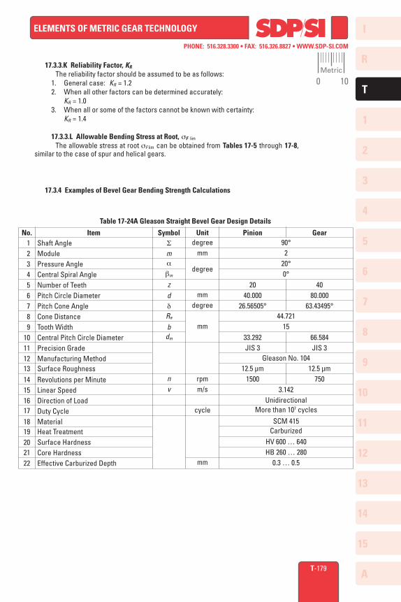
17.3.3.K Reliability Factor, KR
The reliability factor should be assumed to be as follows: 1. General case: KR = 1.2 2. When all other factors can be determined accurately: KR = 1.0 3. When all or some of the factors cannot be known with certainty: KR = 1.4
17.3.3.L Allowable Bending Stress at Root, sF lim
The allowable stress at root sF lim can be obtained from Tables 17-5 through 17-8, similar to the case of spur and helical gears.
S
ma
bm
zddRe
bdm
nv
17.3.4 Examples of Bevel Gear Bending Strength Calculations
Table 17-24A Gleason Straight Bevel Gear Design Details
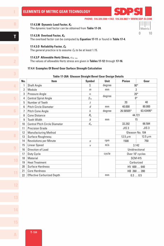
No. Item Symbol Unit Pinion Gear 1 2 3 4 5 6 7 8 910111213141516171819202122
Shaft AngleModulePressure AngleCentral Spiral AngleNumber of TeethPitch Circle DiameterPitch Cone AngleCone DistanceTooth WidthCentral Pitch Circle DiameterPrecision GradeManufacturing MethodSurface RoughnessRevolutions per MinuteLinear SpeedDirection of LoadDuty CycleMaterialHeat TreatmentSurface HardnessCore HardnessEffective Carburized Depth
degreemm
degree
mmdegree
mm
rpmm/s
cycle
mm
90°2
20°0°
44.72115
Gleason No. 104
3.142Unidirectional
More than 107 cycles
SCM 415Carburized
HV 600 … 640HB 260 … 280
0.3 … 0.5
2040.000
26.56505°
33.292JIS 3
12.5 µm1500
4080.000
63.43495°
66.584JIS 3
12.5 µm750
Metric
0 10
I
R
1
2
3
4
5
6
7
8
9
10
11
12
13
T
14
15
A
PHONE: 516.328.3300 • FAX: 516.326.8827 • WWW.SDP-SI.COM
ELEMENTS OF METRIC GEAR TECHNOLOGY
42.5
2.387
1.8
177.3
T-180
0° 2
1544.721
0.6131.01.151.01.0
1.41.01.2
No. Item Symbol Unit Pinion Gear 1 2 3 4 5 6 7 8 9101112131415
16
Central Spiral AngleAllowable Bending Stress at RootModuleTooth WidthCone DistanceTooth Profile FactorLoad Distribution FactorSpiral Angle FactorCutter Diameter Effect FactorLife FactorDimension FactorTooth Flank Load Distribution FactorDynamic Load FactorOverload FactorReliability FactorAllowable Tangential Force at Central Pitch Circle
bm
sF lim
mbRe
YF
Ye
Yb
YC
KL
KFX
KM
KV
KO
KR
Ft lim
degreekgf/mm2
mm
kgf
42.5
2.369
1.8
178.6
Table 17-24B Bending Strength Factors for Gleason Straight Bevel Gear
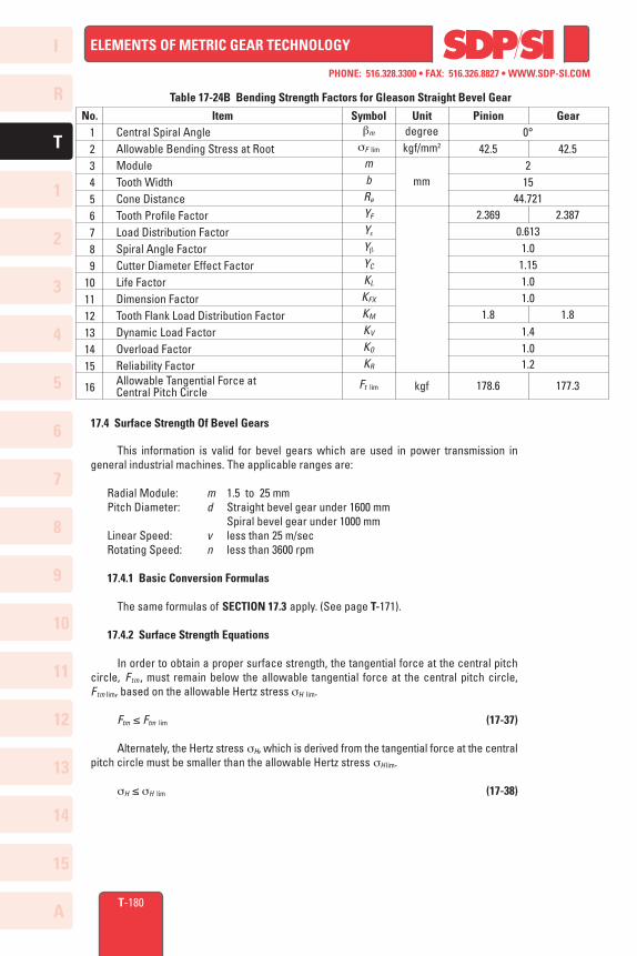
17.4 Surface Strength Of Bevel Gears
This information is valid for bevel gears which are used in power transmission in general industrial machines. The applicable ranges are:
Radial Module: m 1.5 to 25 mm Pitch Diameter: d Straight bevel gear under 1600 mm Spiral bevel gear under 1000 mm Linear Speed: v less than 25 m/sec Rotating Speed: n less than 3600 rpm
17.4.1 Basic Conversion Formulas
The same formulas of SECTION 17.3 apply. (See page T-171).
17.4.2 Surface Strength Equations
In order to obtain a proper surface strength, the tangential force at the central pitch circle, Ftm , must remain below the allowable tangential force at the central pitch circle, Ftm lim, based on the allowable Hertz stress sH lim.
Ftm ≤ Ftm lim (17-37)
Alternately, the Hertz stress sH, which is derived from the tangential force at the central pitch circle must be smaller than the allowable Hertz stress sH lim.
sH ≤ sH lim (17-38)
I
R
1
2
3
4
5
6
7
8
9
10
11
12
13
T
14
15
A
PHONE: 516.328.3300 • FAX: 516.326.8827 • WWW.SDP-SI.COM
ELEMENTS OF METRIC GEAR TECHNOLOGY
T-181
The allowable tangential force at the central pitch circle, Ftm lim, in kgf can be calculated from Equation (17-39).
sH lim d1 Re – 0.5 b u 2 Ftm lim = [(–––––)2 ––––– ––––––––– b ––––– ] ZM cos d1 Re u 2 + 1
KH L ZL ZR ZV ZW KHX 1 1• [(–––––––––––––––)2 ––––––– –––– ] (17-39) ZH Ze Zb KH b KV KO CR
2
The Hertz stress, sH (kgf/mm2) is calculated from Equation (17-40).
–––––––––––––––––––––––– cos d1 Ftm u
2 + 1 Re sH =–––––––– –––––– –––––––– d1 b u 2 Re – 0.5 b
–––––––––– ZH ZM Ze Zb • [–––––––––––––– KHbKVKO CR ] (17-40) KHLZLZR ZV ZWKHX
17.4.3 Determination of Factors In Surface Strength Equations
17.4.3.A Tooth Width, b (mm) This term is defined as the tooth width on the pitch cone. For a meshed pair, the narrower gear's "b " is used for strength calculations.
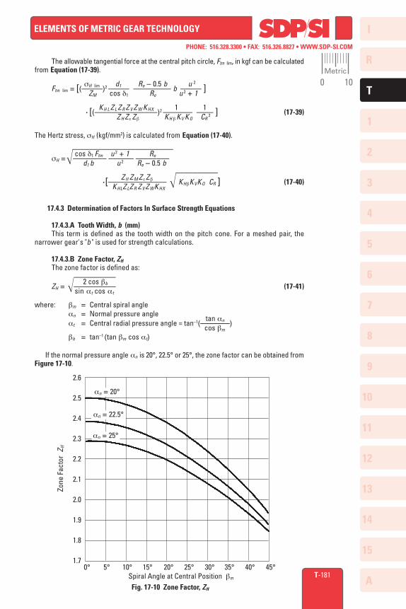
17.4.3.B Zone Factor, ZH
The zone factor is defined as: –––––––––– 2 cos bb ZH = –––––––––– (17-41) sin at cos at
where: bm = Central spiral angle an = Normal pressure angle tan an at = Central radial pressure angle = tan–1(–––––––) cos bm
bb = tan–1 (tan bm cos at) If the normal pressure angle an is 20°, 22.5° or 25°, the zone factor can be obtained from Figure 17-10.
2.6
2.5
2.4
2.3
2.2
2.1
2.0
1.9
1.8
1.70° 5° 10° 15° 20° 25° 30° 35° 40° 45°
Spiral Angle at Central Position bm
Zone
Fac
tor
Z H
Fig. 17-10 Zone Factor, ZH
an = 20°
an = 25°
an = 22.5°
Metric
0 10
I
R
1
2
3
4
5
6
7
8
9
10
11
12
13
T
14
15
A
PHONE: 516.328.3300 • FAX: 516.326.8827 • WWW.SDP-SI.COM
ELEMENTS OF METRIC GEAR TECHNOLOGY
T-182
17.4.3.C Material Factor, ZM
The material factor, ZM , is obtainable from Table 17-9.
17.4.3.D Contact Ratio Factor, Ze
The contact ratio factor is calculated from the equations below.
Straight bevel gear: Ze = 1.0 Spiral bevel gear: –––––––––– eb when ea ≤ 1, Ze = 1 – eb + –– (17-42) ea ––– 1 when eb > 1, Ze = ––– ea
where: ea = Radial Contact Ratio eb = Overlap Ratio
17.4.3.E Spiral Angle Factor, Z b Little is known about these factors, so usually it is assumed to be unity.
Zb = 1.0 (17-43)
17.4.3.F Life Factor, KHL
The life factor for surface strength is obtainable from Table 17-10.
17.4.3.G Lubricant Factor, ZL
The lubricant factor, ZL , is found in Figure 17-3.
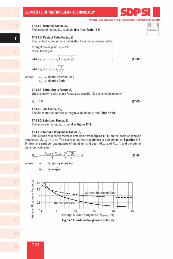
17.4.3.H Surface Roughness Factor, ZR
The surface roughness factor is obtainable from Figure 17-11 on the basis of average roughness, Rmaxm, in µ m. The average surface roughness is calculated by Equation (17-44) from the surface roughnesses of the pinion and gear (Rmax1 and Rmax 2), and the center distance, a, in mm. ––––– Rmax 1 + Rmax 2 100 Rmaxm = ––––––––––––
3––––– (µ m) (17-44) 2 a
where: a = Rm (sin d1 + cos d1) b Rm = Re – ––– 2
1 5 10 15 20 25Average Surface Roughness, Rmax m (µ m)
Fig. 17-11 Surface Roughness Factor, ZR
1.1
1.0
0.9
0.8
0.7
Surface Hardened Gear
Normalized Gear
Surf
ace
Rou
ghne
ss F
acto
r, Z R
Metric
0 10
I
R
1
2
3
4
5
6
7
8
9
10
11
12
13
T
14
15
A
PHONE: 516.328.3300 • FAX: 516.326.8827 • WWW.SDP-SI.COM
ELEMENTS OF METRIC GEAR TECHNOLOGY
T-183
17.4.3.I Sliding Speed Factor, ZV
The sliding speed factor is obtained from Figure 17-5 based on the pitch circle linear speed.
17.4.3.J Hardness Ratio Factor, ZW
The hardness ratio factor applies only to the gear that is in mesh with a pinion which is quenched and ground. The ratio is calculated by Equation (17-45).
HB2 – 130 ZW = 1.2 – –––––––– (17-45) 1700
where Brinell hardness of the gear is: 130 ≤ HB2 ≤ 470
If the gear's hardness is outside of this range, ZW is assumed to be unity.
ZW = 1.0 (17-46)
17.4.3.K Dimension Factor, KHX
Since, often, little is known about this factor, it is assumed to be unity.
KHX = 1.0 (17-47)
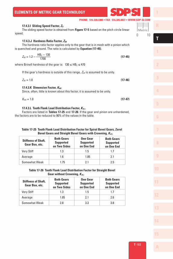
17.4.3.L Tooth Flank Load Distribution Factor, KH b
Factors are listed in Tables 17-25 and 17-26. If the gear and pinion are unhardened, the factors are to be reduced to 90% of the values in the table.
Both GearsSupported
on Two Sides
One GearSupportedon One End
Both GearsSupportedon One End
Very Stiff
Average
Somewhat Weak
1.3
1.6
1.75
1.5
1.85
2.1
1.7
2.1
2.5
Stiffness of Shaft,Gear Box, etc.
Table 17-26 Tooth Flank Load Distribution Factor for Straight Bevel Gear without Crowning, KH b
Both GearsSupported
on Two Sides
One GearSupportedon One End
Both GearsSupportedon One End
Very Stiff
Average
Somewhat Weak
1.3
1.85
2.8
1.5
2.1
3.3
1.7
2.6
3.8
Stiffness of Shaft, Gear Box, etc.
Table 17-25 Tooth Flank Load Distribution Factor for Spiral Bevel Gears, Zerol Bevel Gears and Straight Bevel Gears with Crowning, KH b
Metric
0 10
I
R
1
2
3
4
5
6
7
8
9
10
11
12
13
T
14
15
A
PHONE: 516.328.3300 • FAX: 516.326.8827 • WWW.SDP-SI.COM
ELEMENTS OF METRIC GEAR TECHNOLOGY
4080.000
63.43495°
66.584JIS 3
12.5 µ m750
90°2
20°0°
44.72115
Gleason No. 104
3.142Unidirectional
Over 107 cyclesSCM 415
CarburizedHV 600 … 640HB 260 … 280
0.3 … 0.5
T-184
17.4.3.M Dynamic Load Factor, KV
The dynamic load factor can be obtained from Table 17-24.
17.4.3.N Overload Factor, KO
The overload factor can be computed by Equation 17-11 or found in Table 17-4.
17.4.3.O Reliability Factor, CR
The general practice is to assume CR to be at least 1.15.
17.4.3.P Allowable Hertz Stress, sH l im
The values of allowable Hertz stress are given in Tables 17-12 through 17-16.
17.4.4 Examples Of Bevel Gear Surface Strength Calculation
S
ma
bm
zdd
Re
bdm
nv
Table 17-26A Gleason Straight Bevel Gear Design Details
No. Item Symbol Unit Pinion Gear 1 2 3 4 5 6 7 8 910111213141516171819202122
Shaft AngleModulePressure AngleCentral Spiral AngleNumber of TeethPitch Circle DiameterPitch Cone AngleCone DistanceTooth WidthCentral Pitch Circle DiameterPrecision GradeManufacturing MethodSurface RoughnessRevolutions per MinuteLinear SpeedDirection of LoadDuty CycleMaterialHeat TreatmentSurface HardnessCore HardnessEffective Carburized Depth
degreemm
degree
mmdegree
mm
rpmm/s
cycle
mm
2040.000
26.56505°
33.292JIS 3
12.5 µ m1500
Metric
0 10
I
R
1
2
3
4
5
6
7
8
9
10
11
12
13
T
14
15
A
PHONE: 516.328.3300 • FAX: 516.326.8827 • WWW.SDP-SI.COM
ELEMENTS OF METRIC GEAR TECHNOLOGY
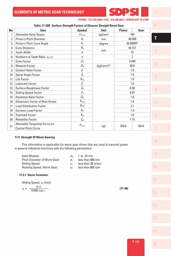
sH lim
d1
d1
Re
buZH
ZM
Ze
Zb
KHL
ZL
ZR
ZV
ZW
KHX
KH b
KV
KO
CR
Ft lim
16440.000
26.56505°44.721
152
2.49560.61.01.01.01.00.900.971.01.02.11.41.01.15
103.0 103.0
kgf/mm2
mmdegree
mm
(kgf/mm2)0.5
kgf
T-185
Table 17-26B Surface Strength Factors of Gleason Straight Bevel Gear
No. Item Symbol Unit Pinion Gear 1 2 3 4 5 6 7 8 91011121314151617181920
21
Allowable Hertz StressPinion's Pitch DiameterPinion's Pitch Cone AngleCone DistanceTooth WidthNumbers of Teeth Ratio z2 / z1
Zone FactorMaterial FactorContact Ratio FactorSpiral Angle FactorLife FactorLubricant FactorSurface Roughness FactorSliding Speed FactorHardness Ratio FactorDimension Factor of Root StressLoad Distribution FactorDynamic Load FactorOverload FactorReliability FactorAllowable Tangential Force on Central Pitch Circle
17.5 Strength Of Worm Gearing
This information is applicable for worm gear drives that are used to transmit power in general industrial machines with the following parameters:
Axial Module: mx 1 to 25 mm Pitch Diameter of Worm Gear: d2 less than 900 mm Sliding Speed: vs less than 30 m/sec Rotating Speed, Worm Gear: n2 less than 600 rpm
17.5.1 Basic Formulas:
Sliding Speed, vs (m/s) d1 n1 vs = ––––––––––– (17-48) 19100 cos g
I
R
1
2
3
4
5
6
7
8
9
10
11
12
13
T
14
15
A
PHONE: 516.328.3300 • FAX: 516.326.8827 • WWW.SDP-SI.COM
ELEMENTS OF METRIC GEAR TECHNOLOGY
T-186
17.5.2 Torque, Tangential Force and Efficiency
(1) Worm as Driver Gear (Speed Reducing)
Ft d2 T2 = –––––– 2000 T2 Ft d2 T1 = –––– = ––––––––– u ηR 2000 u ηR (17-49) µ tan g (1 – tan g
––––––)
cos an ηR = –––––––––––––––––––– µ tan g + –––––– cos an
where: T2 = Nominal torque of worm gear (kg • m) T1 = Nominal torque of worm (kgf • m) Ft = Nominal tangential force on worm gear's pitch circle (kgf) d2 = Pitch diameter of worm gear (mm) u = Teeth number ratio = z2 /zw
ηR = Transmission efficiency, worm driving (not including bearing loss, lubricant agitation loss, etc.)
µ = Friction coefficient
(2) Worm Gear as Driver Gear (Speed Increasing)
Ftd2 T2 = –––––– 2000 T2 ηI Ft d2ηI T1 = –––– = ––––– u 2000 u (17-50) µ tan g – –––––– cos an ηI = –––––––––––––––––––– µ tan g (1 + tan g ––––––) cos an
where: ηI = Transmission efficiency, worm gear driving (not including bearing loss, lubricant agitation loss, etc.)
17.5.3 Friction Coefficient, µ
The friction factor varies as sliding speed changes. The combination of materials is important. For the case of a worm that is carburized and ground, and mated with a phosphorous bronze worm gear, see Figure 17-12. For some other materials, see Table 17-27. For lack of data, friction coefficient of materials not listed in Table 17-27 are very difficult to obtain. H.E. Merritt has offered some further information on this topic. See Reference 9.
Metric
0 10

I
R
1
2
3
4
5
6
7
8
9
10
11
12
13
T
14
15
A
PHONE: 516.328.3300 • FAX: 516.326.8827 • WWW.SDP-SI.COM
ELEMENTS OF METRIC GEAR TECHNOLOGY
T-187
0 0.001 0.01 0.05 0.1 0.2 0.4 0.6 1 1.5 2 3 4 5 6 7 8 9 10 12 14 16 18 20 22 24 26 30Sliding Speed
0.150
0.120
0.1000.0900.0800.0700.060
0.050
0.040
0.030
0.020
0.015
0.012
Coef
ficie
nt o
f Fric
tion
Fig. 17-12 Friction Coefficient, µ
Combination of Materials
Cast Iron and Phosphor Bronze
Cast Iron and Cast Iron
Quenched Steel and Aluminum Alloy
Steel and Steel
µ
µ in Figure 17-12 times 1.15
µ in Figure 17-12 times 1.33
µ in Figure 17-12 times 1.33
µ in Figure 17-12 times 2.00
Table 17-27 Combinations of Materials and Their Coefficients of Friction, µ
17.5.4 Surface Strength of Worm Gearing Mesh
(1) Calculation of Basic Load Provided dimensions and materials of the worm pair are known, the allowable load is as follows: Ft lim = Allowable tangential force (kgf) ZLZMZR = 3.82 Kv Kn Sc lim Zd2
0.8 mx –––––– (17-51) KC
T2 lim = Allowable worm gear torque (kgf • m) ZLZMZR = 0.00191 Kv Kn Sc lim Zd2
1.8 mx ––––– (17-52) KC
(2) Calculation of Equivalent Load The basic load Equations (17-51) and (17-52) are applicable under the conditions of no impact and the pair can operate for 26000 hours minimum. The condition of "no impact" is defined as the starting torque which must be less than 200% of the rated torque; and the frequency of starting should be less than twice per hour.
I
R
1
2
3
4
5
6
7
8
9
10
11
12
13
T
14
15
A
PHONE: 516.328.3300 • FAX: 516.326.8827 • WWW.SDP-SI.COM
ELEMENTS OF METRIC GEAR TECHNOLOGY
T-188
An equivalent load is needed to compare with the basic load in order to determine an actual design load, when the conditions deviate from the above. Equivalent load is then converted to an equivalent tangential force, Fte, in kgf:
Fte = Ft Kh Ks (17-53)
and equivalent worm gear torque, T2e, in kgf • m:
T2e = T2 Kh Ks (17-54)
(3) Determination of Load Under no impact condition, to have life expectancy of 26000 hours, the following relationships must be satisfied:
Ft ≤ Ft lim or T2 ≤ T2 lim (17-55)
For all other conditions:
Fte ≤ Ft lim or T2e ≤ T2 lim (17-56)
NOTE: If load is variable, the maximum load should be used as the criterion.
17.5.5 Determination of Factors in Worm Gear Surface Strength Equations
17.5.5.A Tooth Width of Worm Gear, b2 (mm)
Tooth width of worm gear is defined as in Figure 17-13.
17.5.5.B Zone Factor, Z
If b2 < 2.3 mxQ + 1 , then: b2 Z = (Basic zone factor) x ––––––––––– 2 mx Q + 1 (17-57) If b2 ≥ 2.3 mxQ + 1 , then: Z = (Basic zone factor) x 1.15
where: Basic Zone Factor is obtained from Table 17-28
d1 Q : Diameter factor = ––– mx
zw : number of worm threads
Fig. 17-13 Tooth Width of Worm Gear
b2 b2
Metric
0 10

I
R
1
2
3
4
5
6
7
8
9
10
11
12
13
T
14
15
A
PHONE: 516.328.3300 • FAX: 516.326.8827 • WWW.SDP-SI.COM
ELEMENTS OF METRIC GEAR TECHNOLOGY
T-189
Q zw
7
1.052
1.055
0.989
0.981
7.5
1.065
1.099
1.109
1.098
8
1.084
1.144
1.209
1.204
8.5
1.107
1.183
1.260
1.301
9
1.128
1.214
1.305
1.380
9.5
1.137
1.223
1.333
1.428
10
1.143
1.231
1.350
1.460
11
1.160
1.250
1.365
1.490
12
1.202
1.280
1.393
1.515
13
1.260
1.320
1.422
1.545
14
1.318
1.360
1.442
1.570
17
1.402
1.447
1.532
1.666
20
1.508
1.575
1.674
1.798
1
2
3
4
Table 17-28 Basic Zone Factors
17.5.5.C Sliding Speed Factor, Kv
The sliding speed factor is obtainable from Figure 17-14, where the abscissa is the pitch line linear velocity.
Fig. 17-14 Sliding Speed Factor, Kv
1.0
0.9
0.8
0.7
0.6
0.5
0.4
0.3
0.2
0.1
Slid
ing
Spee
d Fa
ctor
KV
0 0.001 0.01 0.05 0.1 0.2 0.4 0.6 1 1.5 2 3 4 5 6 7 8 9 10 11 12 14 16 18 20 22 24 26 30Sliding Speed vs (m/s)
17.5.5.D Rotating Speed Factor, Kn
The rotating speed factor is presented in Figure 17-15 as a function of the worm gear's rotating speed, n2.
17.5.5.E Lubricant Factor, ZL
Let ZL = 1.0 if the lubricant is of proper viscosity and has antiscoring additives. Some bearings in worm gear boxes may need a low viscosity lubricant. Then ZL is to be less than 1.0. The recommended kinetic viscosity of lubricant is given in Table 17-29.
Metric
0 10
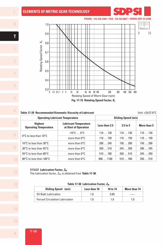
I
R
1
2
3
4
5
6
7
8
9
10
11
12
13
T
14
15
A
PHONE: 516.328.3300 • FAX: 516.326.8827 • WWW.SDP-SI.COM
ELEMENTS OF METRIC GEAR TECHNOLOGY
T-190
1.0
0.9
0.8
0.7
0.6
0.5
0.4
0.3
Fig. 17-15 Rotating Speed Factor, Kn
Rota
ting
Spee
d Fa
ctor
Kn
0 0.1 0.5 1 2 4 10 20 40 60 80 100 200 300 400 500 600Rotating Speed of Worm Gear (rpm)
Table 17-29 Recommended Kinematic Viscosity of Lubricant Unit: cSt/37.8°C
HighestOperating Temperature
Lubricant Temperatureat Start of Operation
110 … 130
110 … 150
150 … 200
245 … 350
350 … 510
510 … 780
110 … 130
110 … 150
200 … 245
350 … 510
510 … 780
900 … 1100
110 … 130
110 … 150
150 … 200
200 … 245
245 … 350
350 … 510
Operating Lubricant Temperature Sliding Speed (m/s)
Less than 2.5 2.5 to 5 More than 5
0°C to less than 10°C
10°C to less than 30°C
30°C to less than 55°C
55°C to less than 80°C
80°C to less than 100°C
–10°C … 0°C
more than 0°C
more than 0°C
more than 0°C
more than 0°C
more than 0°C
17.5.5.F Lubrication Factor, ZM
The lubrication factor, ZM, is obtained from Table 17-30.
Table 17-30 Lubrication Factor, ZM
Sliding Speed (m/s)
Oil Bath Lubrication
Forced Circulation Lubrication
Less than 10
1.0
1.0
10 to 14
0.85
1.0
More than 14
–––
1.0
Metric
0 10
I
R
1
2
3
4
5
6
7
8
9
10
11
12
13
T
14
15
A
PHONE: 516.328.3300 • FAX: 516.326.8827 • WWW.SDP-SI.COM
ELEMENTS OF METRIC GEAR TECHNOLOGY
T-191
17.5.5.G Surface Roughness Factor, ZR
This factor is concerned with resistance to pitting of the working surfaces of the teeth. Since there is insufficient knowledge about this phenomenon, the factor is assumed to be 1.0.
ZR = 1.0 (17-58)
It should be noted that for Equation (17-58) to be applicable, surfaces roughness of the worm and worm gear must be less than 3 µ m and 12 µ m respectively. If either is rougher, the factor is to be adjusted to a smaller value.
17.5.5.H Contact Factor, Kc
Quality of tooth contact will affect load capacity dramatically. Generally, it is difficult to define precisely, but JIS B 1741 offers guidelines depending on the class of tooth contact.
Class A Kc = 1.0 (17-59) Class B, C Kc > 1.0
Table 17-31 gives the general values of Kc depending on the JIS tooth contact class.
17.5.5.I Starting Factor, Ks
This factor depends upon the magnitude of starting torque and the frequency of starts. When starting torque is less than 200% of rated torque, Ks factor is per Table 17-32.
17.5.5.J Time Factor, Kh
This factor is a function of the desired life and the impact environment. See Table 17-33. The expected lives in between the numbers shown in Table 17-33 can be interpolated.
Table 17-31 Classes of Tooth Contact and General Values of Contact Factor, Kc
More than 50% of Effective Width of ToothMore than 35% ofEffective Width of ToothMore than 20% ofEffective Width of Tooth
More than 40% of Effective Height of ToothMore than 30% ofEffective Height of ToothMore than 20% ofEffective Height of Tooth
Class
A
B
C
Proportion of Tooth Contact
Tooth Width Direction Tooth Height DirectionKC
1.0
1.3 … 1.4
1.5 … 1.7
Table 17-32 Starting Factor, Ks
1.0 1.07 1.13 1.18
Less than 2 2 … 5 5 … 10 More than 10
Starting Frequency per HourStartingFactor
Ks
Metric
0 10
I
R
1
2
3
4
5
6
7
8
9
10
11
12
13
T
14
15
A
PHONE: 516.328.3300 • FAX: 516.326.8827 • WWW.SDP-SI.COM
ELEMENTS OF METRIC GEAR TECHNOLOGY
T-192
Table 17-33 Time Factor, Kh
*NOTE: For a machine that operates 10 hours a day, 260 days a year; this number corresponds to ten years of operating life.
ExpectedLife
Uniform Load Medium Impact Strong Impact
Impact from Load
Kh
Impact fromPrime Mover
1500 Hours 5000 Hours26000 Hours*60000 Hours 1500 Hours 5000 Hours26000 Hours*60000 Hours 1500 Hours 5000 Hours26000 Hours*60000 Hours
Uniform Load(Motor, Turbine,Hydraulic Motor)
Light Impact(Multicylinderengine)
Medium Impact(Single cylinderengine)
0.80 0.901.0
1.25
0.901.0
1.25 1.501.0
1.25 1.50 1.75
0.901.0
1.25 1.50
1.0 1.25 1.50 1.75 1.25 1.50 1.702.0
1.0 1.25 1.50 1.75
1.25 1.50 1.752.0
1.50 1.752.0
2.25
17.5.5.K Allowable Stress Factor, Sc lim
Table 17-34 presents the allowable stress factors for various material combinations. Note that the table also specifies governing limits of sliding speed, which must be adhered to if scoring is to be avoided.
Table 17-34 Allowable Stress Factor for Surface Strength, Sc lim
*NOTE: The value indicates the maximum sliding speed within the limit of the allowable stress factor, Sc lim. Even when the allowable load is below the allowable stress level, if the sliding speed exceeds the indicated limit, there is danger of scoring gear surfaces.
Sliding Speed Limit before Scoring
(m/s) *
Material ofWorm Gear
Material of Worm Sc lim
Phosphor BronzeCentrifugal Casting
Phosphor BronzeChilled Casting
Phosphor Bronze Sand Molding or Forging
Aluminum Bronze
Brass
Ductile Cast Iron
Cast Iron (Perlitic)
Alloy Steel Carburized & QuenchedAlloy Steel HB 400Alloy Steel HB 250
Alloy Steel Carburized & QuenchedAlloy Steel HB 400Alloy Steel HB 250
Alloy Steel Carburized & QuenchedAlloy Steel HB 400Alloy Steel HB 250
Alloy Steel Carburized & QuenchedAlloy Steel HB 400Alloy Steel HB 250
Alloy Steel HB 400Alloy Steel HB 250
Ductile Cast Iron but with a higherhardness than the worm gear
Phosphor Bronze Casting andForging
Cast Iron but with a higher hardness than the worm gear
1.551.341.12
1.271.050.88
1.050.840.70
0.840.670.56
0.490.42
0.70
0.63
0.42
302010
302010
302010
201510
85
5
2.5
2.5
I
R
1
2
3
4
5
6
7
8
9
10
11
12
13
T
14
15
A
PHONE: 516.328.3300 • FAX: 516.326.8827 • WWW.SDP-SI.COM
ELEMENTS OF METRIC GEAR TECHNOLOGY
T-193
17.5.6 Examples Of Worm Mesh Strength Calculation
mm
kgf
Table 17-35B Surface Strength Factors and Allowable Force
No. Item Symbol Unit Worm Gear 1 2 3 4 5 6 7 8 91011
Axial ModuleWorm Gear Pitch DiameterZone FactorSliding Speed FactorRotating Speed FactorLubricant FactorLubrication FactorSurface Roughness FactorContact FactorAllowable Stress FactorAllowable Tangential Force
mx
d2
ZKv
Kn
ZL
ZM
ZR
KC
SC lim
Ft lim
280
1.51570.490.661.01.01.01.0
0.6783.5
128
14( )
Grinding3.2 µ m
1500
S45CInduction Hardening
HS 63 … 68
Table 17-35A Worm and Worm Gear Design Details
220°
4.08562
2.205
4080
–––20
Hobbing12.5 µ m
37.5
Al BC2––––––
No. Item Symbol Unit Worm Worm Gear 1 2 3 4 5 6 7 8 91011121314
Axial ModuleNormal Pressure AngleNo. of Threads, No. of TeethPitch DiameterLead AngleDiameter FactorTooth WidthManufacturing MethodSurface RoughnessRevolutions per MinuteSliding SpeedMaterialHeat TreatmentSurface Hardness
mx
an
zw , z2
dg
Qb
nvs
mmdegree
mmdegree
mm
rpmm/s