
I-AUV Docking and Intervention in a Subsea Panel · I-AUV Docking and Intervention in a Subsea...
7
I-AUV Docking and Intervention in a Subsea Panel Narc´ ıs Palomeras 1 , Antonio Pe˜ nalver 2 , Miquel Massot-Campos 3 , Guillem Vallicrosa 1 , Pep Llu´ ıs Negre 3 , J. Javier Fern´ andez 2 , Pere Ridao 1 , Pedro J. Sanz 2 , Gabriel Oliver-Codina 3 , Albert Palomer 1 . Abstract— While commercially available autonomous under- water vehicles (AUVs) are routinely used in survey missions, a new set of applications exist which clearly demand intervention capabilities: the maintenance of permanent underwater struc- tures as well as the recovery of benthic stations or black-boxes are a few of them. These tasks are addressed nowadays using manned submersibles or work-class remotely operated vehicles (ROVs), equipped with teleoperated arms under human super- vision. In the context of the TRITON Spanish funded project, a subsea panel docking and an intervention procedure are proposed. The light-weight intervention AUV (I-AUV) Girona 500 is used to autonomously dock into a subsea panel using a funnel-based docking method for passive accommodation. Once docked, an autonomous fixed-based manipulation system, which uses feedback from a digital camera, is used to turn a valve and plug/unplug a connector. The paper presents the techniques used for the autonomous docking and manipulation as well as how the adapted subsea panel has been designed to facilitate such operations. I. INTRODUCTION A large number of applications exist in the underwater do- main that go beyond the survey capabilities. The maintenance of permanent observatories, submerged oil wells, cabled sensor networks, pipes, and the deployment and recovery of benthic stations, or the search and recovery of black- boxes are just some of them. Nowadays, these tasks require the use of work-class remotely operated vehicles (ROVs) deployed from dynamic positioning (DP) vessels making them very expensive. Despite several underwater intervention systems were developed during the 90’s [1], [2], [3], [4], it was not until the 1st decade of the 21th century that field demonstrations arrived. Very successful approaches were based on hybrid ROV/AUV concepts like the one proposed by the SWIM- MER project [5] where an AUV shuttle transporting a ROV, autonomously homes and docks into a seabed docking station. Next, the ROV, which is connected through the docking device to a remote operation station, is teleoperated *This work was supported by the Spanish project DPI2011-27977-C03v (TRITON). 1 Universitat de Girona, Computer Vision and Robotics Institute, Cen- tre d’Investigaci´ o en Rob´ otica Submarina (CIRS), 17071 Girona (Spain) npalomer | gvallicrosa | [email protected] 2 Universitat Jaume I, Interactive and Robotic Systems Laboratory (IRSLab), 12071 Castell´ o (Spain) penalvea | fernandj | [email protected] 3 Universitat de les Illes Balears, Systems Robotics and Vision Group, 07122 Palma de Mallorca (Spain) pl.negre | miquel.massot | [email protected] The University of Girona wants to thank the SARTI group for their collaboration in the TRITON project. during the intervention. The system avoids the need for a DP capable ship with the consequent savings. Recently, another hybrid concept appeared, the hybrid ROVs (HROVs) [6], [7]. These vehicles are essentially AUVs reconfigurable as ROVs when tethered through an optical fiber umbilical. Thanks to its ultra light umbilical, HROVs may also be operated from ships of opportunity without DP. When plugged, HROVs behave as conventional ROVs avoiding some of the difficulties related to the cable. Moreover, they have the capability of detaching the cable and surfacing autonomously. Nevertheless, both systems keep the human within the control loop. The first fully autonomous intervention at sea, was demonstrated by the ALIVE project [8], where a hovering capable AUV was able to home to a subsea intervention panel using an imaging sonar, and then, docking into it with hydraulic grasps using visual feedback. Once attached to the panel, a very simple manipulation strategy (fixed base manipulation) was used to open/close a valve. First object manipulation from a floating vehicle (an I- AUV) was achieved in 2009 within SAUVIM project [9]. It was demonstrated the capability of searching for an object whose position was roughly known a priori. The object was endowed with artificial landmarks and the robot autonomously located it and hooked it with a recovery device while hovering. Finally, the first multipurpose object search and recovery strategy was demonstrated in the TRIDENT project in 2012. First, the object was searched using a down- looking camera and photo-mosaicing techniques. Next, it was demonstrated how to autonomously ”hook” the object in a water tank [10]. The experiment was repeated in a harbor environment using a 4 degrees of freedom (DoF) arm [11], and later with a 7 DoF arm endowed with a 3 fingered hand [12] (see Fig. 1.(a)). The TRITON project aims to demonstrate intervention capabilities in a permanent submerged observatory. The intervention tasks to demonstrate are: docking to an adapted subsea panel, fixed-based manipulation for valve turning and connector plugging/unplugging, and free floating manipula- tion for camera dome de-fouling (see Fig. 1.(b)). In this paper the first two tasks are presented. Thus, given a subsea panel equipped with a docking mechanism, and a visual feature-rich panel to allow for real- time vision-based localization, the I-AUV has to start at a random position with the panel in the field of view (it is assumed to have reached the panel vicinity by acoustic means) and dock autonomously to the panel. Next, the I- AUV has to be able to complete an autonomous valve turning
Transcript of I-AUV Docking and Intervention in a Subsea Panel · I-AUV Docking and Intervention in a Subsea...
I-AUV Docking and Intervention in a Subsea Panel
Narcıs Palomeras1, Antonio Penalver2, Miquel Massot-Campos3, Guillem Vallicrosa1, Pep Lluıs Negre3,J. Javier Fernandez2, Pere Ridao1, Pedro J. Sanz2, Gabriel Oliver-Codina3, Albert Palomer1.
Abstract— While commercially available autonomous under-water vehicles (AUVs) are routinely used in survey missions, anew set of applications exist which clearly demand interventioncapabilities: the maintenance of permanent underwater struc-tures as well as the recovery of benthic stations or black-boxesare a few of them. These tasks are addressed nowadays usingmanned submersibles or work-class remotely operated vehicles(ROVs), equipped with teleoperated arms under human super-vision. In the context of the TRITON Spanish funded project,a subsea panel docking and an intervention procedure areproposed. The light-weight intervention AUV (I-AUV) Girona500 is used to autonomously dock into a subsea panel using afunnel-based docking method for passive accommodation. Oncedocked, an autonomous fixed-based manipulation system, whichuses feedback from a digital camera, is used to turn a valveand plug/unplug a connector. The paper presents the techniquesused for the autonomous docking and manipulation as well ashow the adapted subsea panel has been designed to facilitatesuch operations.
I. INTRODUCTION
A large number of applications exist in the underwater do-main that go beyond the survey capabilities. The maintenanceof permanent observatories, submerged oil wells, cabledsensor networks, pipes, and the deployment and recoveryof benthic stations, or the search and recovery of black-boxes are just some of them. Nowadays, these tasks requirethe use of work-class remotely operated vehicles (ROVs)deployed from dynamic positioning (DP) vessels makingthem very expensive. Despite several underwater interventionsystems were developed during the 90’s [1], [2], [3], [4], itwas not until the 1st decade of the 21th century that fielddemonstrations arrived.
Very successful approaches were based on hybridROV/AUV concepts like the one proposed by the SWIM-MER project [5] where an AUV shuttle transporting aROV, autonomously homes and docks into a seabed dockingstation. Next, the ROV, which is connected through thedocking device to a remote operation station, is teleoperated
*This work was supported by the Spanish project DPI2011-27977-C03v(TRITON).
1Universitat de Girona, Computer Vision and Robotics Institute, Cen-tre d’Investigacio en Robotica Submarina (CIRS), 17071 Girona (Spain)npalomer | gvallicrosa | [email protected]
2Universitat Jaume I, Interactive and Robotic Systems Laboratory(IRSLab), 12071 Castello (Spain) penalvea | fernandj |[email protected]
3Universitat de les Illes Balears, Systems Robotics and Vision Group,07122 Palma de Mallorca (Spain) pl.negre | miquel.massot| [email protected]
The University of Girona wants to thank the SARTI group for theircollaboration in the TRITON project.
during the intervention. The system avoids the need for a DPcapable ship with the consequent savings.
Recently, another hybrid concept appeared, the hybridROVs (HROVs) [6], [7]. These vehicles are essentiallyAUVs reconfigurable as ROVs when tethered through anoptical fiber umbilical. Thanks to its ultra light umbilical,HROVs may also be operated from ships of opportunitywithout DP. When plugged, HROVs behave as conventionalROVs avoiding some of the difficulties related to the cable.Moreover, they have the capability of detaching the cableand surfacing autonomously.
Nevertheless, both systems keep the human within thecontrol loop. The first fully autonomous intervention atsea, was demonstrated by the ALIVE project [8], wherea hovering capable AUV was able to home to a subseaintervention panel using an imaging sonar, and then, dockinginto it with hydraulic grasps using visual feedback. Onceattached to the panel, a very simple manipulation strategy(fixed base manipulation) was used to open/close a valve.First object manipulation from a floating vehicle (an I-AUV) was achieved in 2009 within SAUVIM project [9].It was demonstrated the capability of searching for anobject whose position was roughly known a priori. Theobject was endowed with artificial landmarks and the robotautonomously located it and hooked it with a recovery devicewhile hovering. Finally, the first multipurpose object searchand recovery strategy was demonstrated in the TRIDENTproject in 2012. First, the object was searched using a down-looking camera and photo-mosaicing techniques. Next, it wasdemonstrated how to autonomously ”hook” the object in awater tank [10]. The experiment was repeated in a harborenvironment using a 4 degrees of freedom (DoF) arm [11],and later with a 7 DoF arm endowed with a 3 fingered hand[12] (see Fig. 1.(a)).
The TRITON project aims to demonstrate interventioncapabilities in a permanent submerged observatory. Theintervention tasks to demonstrate are: docking to an adaptedsubsea panel, fixed-based manipulation for valve turning andconnector plugging/unplugging, and free floating manipula-tion for camera dome de-fouling (see Fig. 1.(b)). In this paperthe first two tasks are presented.
Thus, given a subsea panel equipped with a dockingmechanism, and a visual feature-rich panel to allow for real-time vision-based localization, the I-AUV has to start ata random position with the panel in the field of view (itis assumed to have reached the panel vicinity by acousticmeans) and dock autonomously to the panel. Next, the I-AUV has to be able to complete an autonomous valve turning
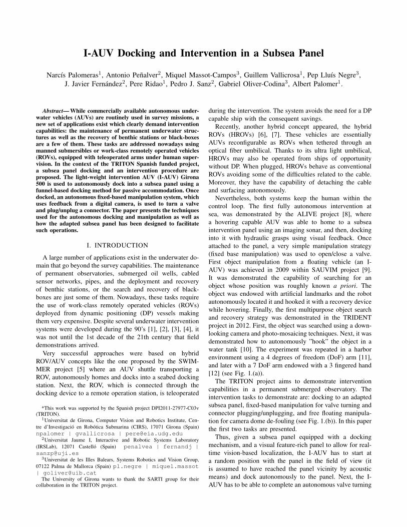
(a) (b)
Fig. 1: (a) TRIDENT project: Girona 500 I-AUV recoveringa black-box with a 7 DoF manipulator autonomously. (b)TRITON concept: Girona 500 I-AUV docked in the subseapermanent observatory OBSEA.
and hot stab connector plugging/unplugging actions.The paper is organized as follows. First, a funnel-based
docking station developed for this project is presented. Next,the docking maneuver is split into: the panel detection bymeans of a vision-based algorithm and the docking ma-neuver. Section V details how the valve and the hot stabconnector position are estimated while the manipulator ini-tialization and the end-effector pose estimation are describedin Section VI. Section VII introduces the procedures to turna valve as well as to plug/unplug the hot stab connector.Once all the elements are presented, the results obtained ina water tank with the Girona 500 I-AUV are discussed inSection VIII before the conclusions.
II. I-AUV FRIENDLY DOCKING STATION
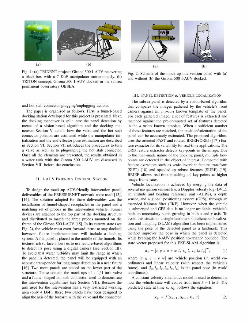
To design the mock-up AUV-friendly intervention panel,deliverables of the FREESUBNET network were used [13],[14]. The solution adopted for these deliverables was theinstallation of funnel-shaped receptacles in the panel and amatching set of probes in the intervention vehicle. Funneldevices are attached to the top part of the docking structureand distributed to match the three probes mounted on theframe of the Girona 500 I-AUV [15]. In its current state (seeFig. 2), the vehicle must exert forward thrust to stay docked,however, future implementations will include a latchingsystem. A flat panel is placed in the middle of the funnels. Itstexture-rich surface allows us to use feature-based algorithmsto detect its pose using a digital camera (see Section III).To avoid that water turbidity may limit the range in whichthe panel is detected, the panel will be equipped with anacoustic transponder for long range detection in a near future[16]. Two more panels are placed on the lower part of thestructure. Those contain the mock-ups of a 1/4 turn valveand a funnel shaped hot stab connector, used to demonstratethe intervention capabilities (see Section VII). Because thearm used for the intervention has a very restricted workingarea (only 4 DoF), these two panels have been designed toalign the axis of the forearm with the valve and the connector.
(a) (b)
Fig. 2: Schema of the mock-up intervention panel with (a)and without (b) the Girona 500 I-AUV docked.
III. PANEL DETECTION & VEHICLE LOCALIZATION
The subsea panel is detected by a vision-based algorithmthat compares the images gathered by the vehicle’s frontcamera against an a priori known template of the panel.For each gathered image, a set of features is extracted andmatched against the pre-computed set of features detectedin the a priori known template. When a sufficient numberof these features are matched, the position/orientation of thepanel can be accurately estimated. The proposed algorithm,uses the oriented FAST and rotated BRIEF(ORB) ([17]) fea-ture extractor for its suitability for real-time applications. TheORB feature extractor detects key-points in the image. Dueto the man-made nature of the docking panel, multiple key-points are detected in the object of interest. Compared withfeature extractors such as scale invariant feature transform(SIFT) [18] and speeded-up robust features (SURF) [19],BRIEF allows real-time matching of key-points at higherimage frame-rates.
Vehicle localization is achieved by merging the data ofseveral navigation sensors (i.e. a Doppler velocity log (DVL),an attitude and heading reference unit (AHRS), a depthsensor, and a global positioning system (GPS)) through anextended Kalman filter (EKF). However, when the vehicleis submerged and GPS data is no longer available, vehicle’sposition uncertainty starts growing in both x and y axis. Toavoid this situation, a single landmark simultaneous localiza-tion and mapping (SLAM) algorithm has been implementedusing the pose of the detected panel as a landmark. Thismethod improves the pose in which the panel is detectedwhile keeping the I-AUV position covariance bounded. Thestate vector proposed for this EKF-SLAM algorithm is:
xk = [x y z u v w lx ly lz lφ lθ lψ]T , (1)
where [x y z u v w] are vehicle position (in world co-ordinates) and linear velocity (with respect the vehicle’sframe), and [lx, ly, lz, lφ, lθ, lψ] is the panel pose (in worldcoordinates).
A constant velocity kinematics model is used to determinehow the vehicle state will evolve from time k− 1 to k. Thepredicted state at time k, x−k follows the equation:
x−k = f(xk−1,nk−1,uk, t), (2)

x−k =
xk−1
yk−1
zk−1
+ R(φkθkψk)
uk−1
vk−1
wk−1
t+ nuk−1
nvk−1
nwk−1
t2
2
uk−1 + nuk−1
t
vk−1 + nvk−1t
wk−1 + nwk−1t
lxk−1
lyk−1
lzk−1
lφk−1
lθk−1
lψk−1
where t is the time period, u = [φ θ ψ] is the control inputgiven by the vehicle AHRS, which determines the currentvehicle orientation, and n = [nu nv nw] is a vector of zero-mean white Gaussian acceleration noise.
Four measurement updates are applied to the filter:DVL velocities ([u, v, w]), depth sensor ([z]) and GPS([x, y]) positions, and landmark (i.e. panel pose) updates([lx, ly, lz, lφ, lθ, lψ]). All these updates follow the model:
zk = Hxk + sk, (3)
where zk is the measurement itself, H is the observationmatrix that relates the state vector with the sensor measure-ment, and sk is the sensor noise. While the H matricesfor position and velocity updates are trivial, the observationmatrix for the landmark update is:
H =
[−RotT 03×3 RotT 03×303×3 03×3 03×3 I3×3
], (4)
where I3×3 denotes the 3× 3 identity matrix, 03×3 denotesthe 3 × 3 zero matrix, and Rot is the vehicle orientationrotation matrix.
IV. DOCKING
The docking maneuver to be demonstrated is composedby four steps: i) the intervention panel must be detectedand mapped by the EKF-SLAM algorithm; ii) the I-AUVhas to approach the panel; iii) once closer a dock homingprocedure is executed; and iv) the vehicle pushes forwardto finalize the mechanical coupling. The Girona 500 I-AUVhas several control modes that can be used to move it butall of them make use of its low-level controller. This low-level controller is a cascade control scheme that allows tocontrol the vehicle by means of pose (position + orientation),twist (linear velocity + angular velocity), and wrench (force+ torque) requests. In general, the output of the first stageof a cascade control scheme is the input of the second andso on. Therefore, when a high level controller requests adesired pose this is transformed into a desired twist, theninto a desired wrench, and finally into a desired setpoint foreach thruster. However, in our proposed implementation eachDoF is treated independently. Thus the high level controllermay request a desired pose, for instance in z or ψ, whilealso requesting a desired velocity in u or a wrench in anyother DoF (see Fig. 3).
Fig. 3: Girona 500 I-AUV low level cascade control scheme.
To reach the panel a waypoint called approaching way-point, placed at 2m in front of the panel, is generated. Theorientation error (ψe) between vehicle’s current pose andthe approaching waypoint is computed according to (5) andrequested to the pose controller together with the waypoint’sdepth.
∆x = x′(t)− x(t),
∆y = y′(t)− y(t),
ψe(t) = atan2(∆y,∆x). (5)
When, ψe(t) is smaller than a user-defined error(angle error), the desired surge (u) is also requestedto the velocity controller following:
u′(t) = min
√
∆2x + ∆2
y
approach factor, 1
·(
1− | ψe(t) |angle error
)·max surge, (6)
with angle error = 0.3 rad, approach factor = 4 andmax surge = 0.6 m/s for Girona 500 I-AUV. When thevehicle reaches a position which euclidean distance fromthe approaching waypoint is smaller than a user defined error(i.e. 0.5 m in our case), the waypoint is considered achieved.For the homing procedure (step iii) a second waypoint calleddocking waypoint, in which the vehicle probes are nearlyinside the docking funnel-shaped receptacles, is computed.While in the previous control mode the vehicle was onlyrequested to move to a desired position ([x, y, z]) now itis requested to move to a specific position and orientation([x, y, z, ψ]). Thus, for the homing procedure, the posecontroller is in charge to move the vehicle, following thewhole cascade control scheme.
If during the homing procedure the panel has been detectedby the vision detection algorithm, providing an accurateposition for both vehicle and intervention panel, the dockingmaneuver finalizes requesting the I-AUV to push forward(i.e. requesting X = 35N to the wrench controller) whilekeeping the linear velocity w and the angular velocity ψat zero (step iv). Otherwise, if the vision system is unable

to detect the panel while performing the homing procedure,this step is aborted and the vehicle returns to the approachingwaypoint.
V. VALVE AND CONNECTOR DETECTION
For the valve/connector detection, a stereo camera hasbeen placed in the bottom hull of the Girona 500 I-AUVpointing to the region where the valve/connector is supposedto be once the vehicle is docked. The three valve endshave been painted in order to detect its pose and rotation(allowing 90◦ turns). Because the connector is not able torotate, only its pose is estimated. Two detection methodshave been implemented, a HSV color detection for the valveand a marker detection for the connector. These algorithmscan run individually or simultaneously to increase robustness.
The first method uses the histogram of hue and saturationin the HSV color space [10]. This method has been adaptedto detect the three painted marks on the valve in bothcameras. The 3D position of the detected blobs are computedby triangulation, and then the positions are matched to theirknown 3D model using an optimal rigid transformation (seeFig. 4). This transformation is defined as follows:
B = R ·A+ t, (7)
where A and B are the points of the detected valveand the known 3D model respectively. R is the rotationfrom the actual valve points to the 3D model frame andt is the translation between their origins. The 3D modelof the valve is defined at the origin of the camera frame.Therefore, computing the optimal rotation and translationbetween the 3D world points and the model will result inthe homogeneous transformation that defines the pose of thevalve relative to the camera frame. To solve equation (7) bothdatasets are moved to the same origin and singular valuedecomposition (SVD) is applied to find the optimal rotation:
H =
N∑i=1
(P iA − CA)(P iB − CB), (8)
[U, S, V ] = SVD(H), (9)
R = V · UT , (10)
where N is the number of points, P i represents theith-point of the corresponding dataset and CA/CB are thecentroids of A and B. Once the optimal rotation has beenfound, the translation can be computed as follows:
t = −R · CA + CB . (11)
The transformation between the valve and the connectoris static due to the rigid structure that joins them and can beeasily measured.
Alternatively, an ARToolkit [20] marker has been placednear to the hot stab connector to provide a more accurate poseof this element. The ARToolkit library provides methods fordetecting the marker using a non-stereo camera as well asdetermining the position and orientation of the marker with
Fig. 4: Valve optimal rigid transformation.
Fig. 5: Manipulation system frames and transformations.
respect to it. It is worth noting than the ARMarker is not onthe connector but near it, so the static transformation betweenthe ARMarker and the connector must be also measured. Ifboth detectors are running simultaneously, the first one isused to estimate the valve’s position/rotation while the latteris used for estimating the connectors position. If only oneis running, the pose of the unknown actuator is computedassuming the measured transformation between them.
VI. ARM INITIALIZATION AND VISUAL SERVOING
Prior to the experiment, the arm must be initialized toknow its zero position in the joint space because the positionsgiven by the hall sensors are relative. To this aim, each jointis moved to its mechanical limit and its zero position is fixed.Later on, the hall effect sensors, located in the electricalmotors, are used to track the joint angles. Nevertheless, theuncertainty in the kinematics model and the non linearities inthe linear-to-circular transmission used to move the rotativejoints by means of electrical driven pistons are responsiblefor the inaccuracy of the Cartesian position of the end-effector, in particular at the boundaries of the workingspace. To solve this issue, a visual servoing approach hasbeen followed. An ARMarker, like the one presented in theprevious section, has been placed in the jaw grip to computethe real position of each joint every time that the ARMarkeris in the camera’s field of view.
In order to obtain the relation between the base of thearm and the camera (bMc) (see Fig. 5), the arm is placed ina position where the camera can clearly see the ARMarker.On one hand, the camera-to-marker transformation (cMm) isestimated using the ARToolkit library. On the other hand, thetransformation from the arm base to the end-effector (bMe) is

obtained using the arm forward kinematics. With these twotransformations and the fixed relation between the markerand the end-effector (mMe), the desired relation (bMc) iscomputed as follows:
bMc =b Me · (cMm ·mMe)−1. (12)
During the intervention, each time that the ARMarker poseis estimated, the transformation between the arm base andthe end-effector is computed applying:
bMe =b Mc ·cMm ·mMe (13)
The position for each joint can be computed applyinginverse kinematics to the obtained transformation bMe. Next,the difference between the position estimated by the visualservoing algorithm and the one measured by the internal halleffect sensors is computed.
offset[1,··· ,n] = estimated[1,··· ,n]− internal[1,··· ,n]. (14)
Between two ARMarker detections, the position of eachjoint is obtained by adding the measured joint position (halleffect sensors) with their offset. This approach reduces thearm inaccuracies ensuring the pose consistency between theend-effector and the robot base.
VII. VALVE TURNING AND CONNECTORUNPLUGGING/PLUGGING
The intervention phase starts once the vehicle is dockedand the detections are available. Two operations are per-formed: turn a valve and unplug/plug a hot stab connector.The main steps followed for the intervention are summa-rized hereinafter. Given an object to manipulate (valve orconnector) and given its pose relative to the camera (cMo),the pose of the object with respect to the arm-base can beeasily computed as follows.
bMo =b Mc ·cMo (15)
Next, two waypoints are defined for the valve: pre-manipulation and manipulation. And four for the connector:pre-manipulation, manipulation, unplug and plug. To reacheach one of these waypoints, the system computes the Carte-sian distance from the end-effector to the desired waypoint(xe). This distance is multiplied by the pseudo-inverse of thearm Jacobian at the end-effector (J+
e ), obtaining the jointvelocities (q) that drive the arm in the Cartesian space to thedesired waypoint:
q = J+e · xe. (16)
Since the arm only has 4 DoF, the orientation in whichthe waypoints are reached is not taken into account, so thelast three rows in the Jacobian, which are referred to theorientation, are set to zero.
Fig. 6: Girona 500 I-AUV docked in a subsea panel unplug-ging a hot stab connector.
VIII. RESULTS
This paper presents a combination of several algorithms toperform an autonomous underwater panel intervention. Thisunmanned intervention consists in docking a vehicle intoan adapted intervention panel in order to turn a valve andplug/unplug a hot stab connector. To the best of the authorsknowledge, this kind of autonomous intervention has neverbeen demonstrated with a light-weight I-AUV.
To validate all the algorithms involved in this task thefollowing setup has been prepared. A mock-up of an inter-vention panel has been deployed in a water tank of 16 × 8× 5 meters. The Girona 500 I-AUV [15] was used in theseexperiments. It has been equipped with a passive dockingsystem, consisting of three probes, and an ECA 4 DoFmanipulator [21] (see Fig. 6). Two cameras have also beenmounted on the vehicle: one, looking forward to estimatethe panel pose and the other pointing down to detect theintervention objects to be manipulated as well as to improvethe manipulator’s end-effector pose (see sections V and VI).
For testing the docking phase, the I-AUV was teleoperatedto a location where the intervention panel was within thethe camera field of view, so that, the EKF-SLAM algorithmmapped the panel as a landmark. Next, the vehicle wasplaced to a random position in the water tank and theautonomous docking maneuver was started. The dockingphase was successfully repeated 11 out of 12 times. In 6of these tests a Seaeye MCT1 thruster was used to generatecurrents in the water tank. The thruster was placed next tothe intervention panel and its setpoint was changed every20 seconds to a random value between the 30% and 70%of its maximum 14kg thrust. The precision achieved afterthe homing procedure, where the vehicle probes should bealigned and nearly touching the funnels in the panel (seeSection IV), was: σx = 2.07 cm, σy = 3.76 cm, σz =1.9 cm, and σψ = 0.76◦. These errors were small enough toachieve the mechanical coupling between the vehicle probes

Fig. 7: Valve detection (top) and ARMarker (bottom) esti-mations in x/y plane.
and the funnels in the panel when the I-AUV pushed forward.The average time to complete the docking procedure was 115seconds.
Both valve and connector detections were influenced bylight changes and occlusions. Even so, the system has beendesigned to work under tenths of meters, where darkness isguaranteed and constant artificial lightning must be used.Regarding the valve detection, the size and shape of themarks changed depending on the vantage point, and thedetected centroid was shifted from its actual center, causingsmall errors. The ARMarker detection showed more reliabil-ity when the marker was closer to the camera, so that thetotal size in pixels was bigger and therefore the computationof its pose was more precise. To estimate the repeatabilityof these errors, a static test was performed assuming thestructure of the I-AUV fixed when it was docked and thearm was not moving. Figure 7 illustrates the valve/connectorpose estimations during a static test of 30 seconds. The lowernumber of points for the valve detection plot is due to the lowfrequency rate of this algorithm. The repeatability error forthe valve detection was 0.57 mm with a standard deviationof 0.53 mm whilst for the ARMarker the average error was0.9 mm with a standard deviation of 0.79 mm.
Figure 8 shows the I-AUV trajectory while performingthe whole intervention task. During the first 99 seconds theI-AUV docked into the intervention panel. Up to second325, the vehicle was performing a valve turning and theunplugging of the hot stab connector. Next, the vehiclewas automatically undocked and then manually moved toa random position in the water tank. At time 343 seconds, asecond docking maneuver was conducted. After 90 seconds,the docking finalized and the connector plugging task wasexecuted. When the connector was plugged again the vehicleundocked at second 481.
Figure 9 shows the trajectory of the end-effector with
Fig. 8: Vehicle pose during the whole intervention task.
respect to the base of the arm during the whole intervention,as well as the waypoints that the end-effector attempted toreach. The rough edges present in some trajectories (e.g.from valve pre-manipulation to valve manipulation way-points) are due to visual servoing algorithm updates in theposition of the end-effector. All the waypoints were reachedwith an average precision of 2 mm between the estimatedend-effector position and the desired waypoint.
It is worth noting that several errors are involved inthe intervention task: the position error of the interventionobjects detected by the vision-based algorithms, the positionerror of the end-effector obtained from the visual-servoingalgorithm combined with the hall sensors, the accuracy errorof the arm controller, and the calibration errors (i.e. bMc,mMe, ...). Although we have seen that all these errors are ofthe order of 1-3 mm, their combination can produce errorsup to 2 cm. To overcome this larger errors, the hot stabis designed with a funnel shape and the end-effector hasbeen V-shaped to mechanically simplify both turning andplugging/unplugging tasks.
IX. CONCLUSIONS AND LESSONS LEARNED
This paper has presented the integration of several systemsin the context of a subsea panel docking and an interventionprocedure performed by the light-weight I-AUV Girona 500.To simplify the overall task, an AUV-friendly interventionpanel has been designed and built. Adapting the panel to ourvehicle has been a key element on the overall mission suc-cess. The feature-based vision algorithm to estimate the panelpose combined with the navigation data gathered by the I-AUV sensors in an EKF-SLAM algorithm has demonstratedto be a reliable solution to improve both the vehicle andpanel position. Regarding the other vision-based algorithmsdeveloped to estimate the position of the elements of interest(i.e. the valve to turn and the connector to plug/unplug) aswell as to improve the estimation of the end-effector position

Fig. 9: End-effector Cartesian trajectory during the interven-tion.
(through a visual servoing algorithm) it must be said thatARMarker-based solutions have been more robust than color-based approaches. While the former have worked out of thebox the latter have required adjustments due to light changes.Initial problems with the position of the manipulator’s end-effector have bee overcome with the inclusion of a visualservoing algorithm that has substantially improved the armaccuracy. The paper, and the accompanying video, reportstwo consecutive intervention maneuvers in a water tank. Inthe first one, the I-AUV docks, turns a valve and unplugsa hot stab connector before undocking. In the second, theI-AUV (still holding the connector) docks again, plugs theconnector, and undocks.
To accomplish the final scenario proposed in the TRITONproject, this same experiment has to be carried out at sea. Tothat end, a transponder will be attached to the interventionpanel and a range-only localization algorithm [16] will beused to detect the panel and navigate towards it. Once thepanel appears in the vehicle’s field of view, the docking andintervention tasks detailed in this paper will be repeated.
REFERENCES
[1] H. H. Wang, S. M. Rock, and M. J. Lees, “Experiments in au-tomatic retrieval of underwater objects with an AUV,” OCEANS’95. MTS/IEEE. Challenges of Our Changing Global Environment.Conference Proceedings, vol. 1, pp. 366–373, 1995.
[2] S. Choi, G. Takashige, and J. Yuh, “Experimental study on anunderwater robotic vehicle: ODIN,” AUV’94. Proceedings of the 1994Symposium Autonomous Underwater Vehicle Technology, pp. 79–84,1994.
[3] V. Rigaud, E. Coste-Maniere, M. Aldon, P. Probert, M. Perrier,P. Rives, D. Simon, D. Lang, J. Kiener, A. Casal, J. Amar, P. Dauchez,and M. Chantler, “UNION: underwater intelligent operation and
navigation,” Robotics & Automation Magazine, IEEE, vol. 5, no. 1,pp. 25–35, 1998.
[4] D. Lane, D. J. O’Brien, M. Pickett, J. Davies, G. Robinson, D. Jones,E. Scott, G. Casalino, G. Bartolini, G. Cannata, A. Ferrara, D. an-geletti, G. Veruggio, R. Bono, P. Virgili, M. Canals, R. Pallas, E. Gar-cia, and C. Smith, “AMADEUS-Advanced Manipulation for DeepUnderwater Sampling,” IEEE Robotics and Automation Magazine,vol. 4, no. 4, pp. 34–45, 1997.
[5] J. Evans, K. Keller, J. Smith, P. Marty, and O. Rigaud, “Docking tech-niques and evaluation trials of the SWIMMER AUV: an autonomousdeployment AUV for work-class ROVs,” OCEANS, 2001. MTS/IEEEConference and Exhibition, vol. 1, pp. 520–528, 2001.
[6] B. Fletcher, C. Young, J. Buescher, L. Whitcomb, A. Bowen, R. Mc-Cabe, and D. Yoerger, “Proof of concept demonstration of the Hy-brid Remotely Operated Vehicle (HROV) light fiber tether system,”OCEANS 2008, pp. 1–6, 2008.
[7] N. Farr, A. Bowen, J. Ware, C. Pontbriand, and M. Tivey, “Anintegrated, underwater optical /acoustic communications system,” inOCEANS 2010 IEEE - Sydney, 2010, pp. 1–6.
[8] J. Evans, P. Redmond, C. Plakas, K. Hamilton, and D. Lane, “Au-tonomous docking for Intervention-AUVs using sonar and video-basedreal-time 3D pose estimation,” OCEANS 2003, vol. 4, pp. 2201–2210,2003.
[9] G. Marani, S. Choi, and J. Yuh, “Underwater Autonomous Manipu-lation for Intervention Missions AUVs,” Ocean Engineering. SpecialIssue: AUV, vol. 36, no. 1, pp. 15–23, 2009.
[10] M. Prats, D. Ribas, N. Palomeras, J. Garcia, V. Nannen, S. Wirth,J. J. Fernandez, J. Beltran, R. Campos, P. Ridao, P. Sanz, G. Oliver,M. Carreras, N. Gracias, R. Marin, and A. Ortiz, “Reconfigurableauv for intervention missions: a case study on underwater objectrecovery,” Intelligent Service Robotics, vol. 5, no. 1, pp. 19–31, 2012.[Online]. Available: http://dx.doi.org/10.1007/s11370-011-0101-z
[11] M. Prats, J. Garcıa, S. Wirth, D. Ribas, P. Sanz, P. Ridao, N. Gracias,and G. Oliver, “Multipurpose autonomous underwater intervention: Asystems integration perspective,” Control & Automation (MED), 201220th Mediterranean Conference on, pp. 1379–1384, 2012.
[12] P. J. Sanz, P. Ridao, G. Oliver, G. Casalino, Y. Petillot, C. Silvestre,C. Melchiorri, and A. Turetta, “TRIDENT: An european projecttargeted to increase the autonomy levels for underwater interventionmissions,” in OCEANS’13 MTS/IEEE, 2013.
[13] S. Krupinski, F. Maurelli, A. Mallios, and P. Sotiropoulos, “TowardsAUV docking on sub-sea structures,” in OCEANS 2009 MTS/IEEE,2009.
[14] P. Sotiropoulos, D. Grosset, G. Giannopoulos, and F. Casadei, “AUVdocking system for existing underwater control panel,” in OCEANS2009 MTS/IEEE, 2009.
[15] D. Ribas, N. Palomeras, P. Ridao, M. Carreras, and A. Mallios,“Girona 500 AUV, from survey to intervention,” IEEE/ASME Trans-actions on Mechatronics, vol. 17(1), pp. 46–53, February 2012.
[16] G. Vallicrosa, P. Ridao, and D. Ribas, “Active range-only beaconlocalization for AUV homing,” in PENDING TO BE ACCEPTED ONIntelligent Robots and Systems (IROS), 2014 IEEE/RSJ InternationalConference on, 2014, pp. –.
[17] E. Rublee, V. Rabaud, K. Konolige, and G. Bradski, “ORB: Anefficient alternative to SIFT or SURF,” in Computer Vision (ICCV),2011 IEEE International Conference on, nov. 2011, p. 25642571.
[18] D. G. Lowe, “Distinctive Image Features from Scale-Invariant Key-points,” Int. J. Comput. Vision, vol. 60, no. 2, p. 91110, Nov. 2004.
[19] H. Bay, A. Ess, T. Tuytelaars, and L. Van Gool, “Speeded-Up RobustFeatures (SURF),” Comput. Vis. Image Underst., vol. 110, no. 3, p.346359, Jun. 2008.
[20] H. Kato and M. Billinghurst, “Marker tracking and hmd calibrationfor a video-based augmented reality conferencing system,” in Aug-mented Reality, 1999. (IWAR ’99) Proceedings. 2nd IEEE and ACMInternational Workshop on, 1999, pp. 85–94.
[21] J. Fernandez, M. Prats, P. Sanz, J. Garcia, R. Marin, D. Robinson,M. Ribas, and P. Ridao, “Grasping for the seabed: Developing anew underwater robot arm for shallow-water intervention,” RoboticsAutomation Magazine, IEEE, vol. 20, no. 4, pp. 121–130, Dec 2013.