I and Q Components in Communications Signalsskatz/katzpage/sdr_project/sdr/I_andQ.pdf · OVERVIEW...
24
SHARLENE KATZ JAMES FLYNN I and Q Components in Communications Signals
-
Upload
nguyentruc -
Category
Documents
-
view
232 -
download
4
Transcript of I and Q Components in Communications Signalsskatz/katzpage/sdr_project/sdr/I_andQ.pdf · OVERVIEW...
S H A R L E N E K A T Z
J A M E S F L Y N N
I and Q Components in Communications Signals
OVERVIEW
Description of I and Q signal representation
Obtaining I and Q components from the USRP
I and Q components of a SSB signal
Using I and Q to demodulate signals
Planning for the Winter/Spring
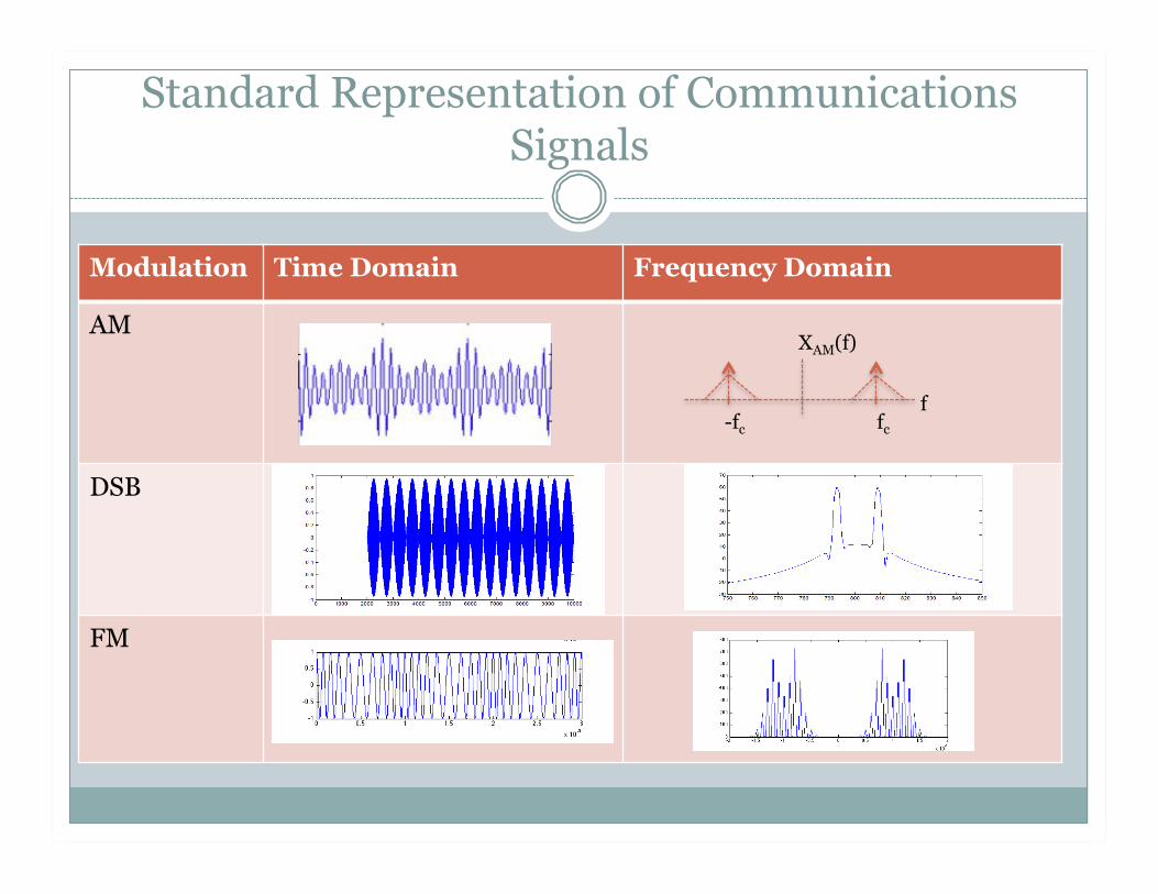
Standard Representation of Communications Signals
Modulation Time Domain Frequency Domain
AM
DSB
FM
XAM(f)
f -fc fc
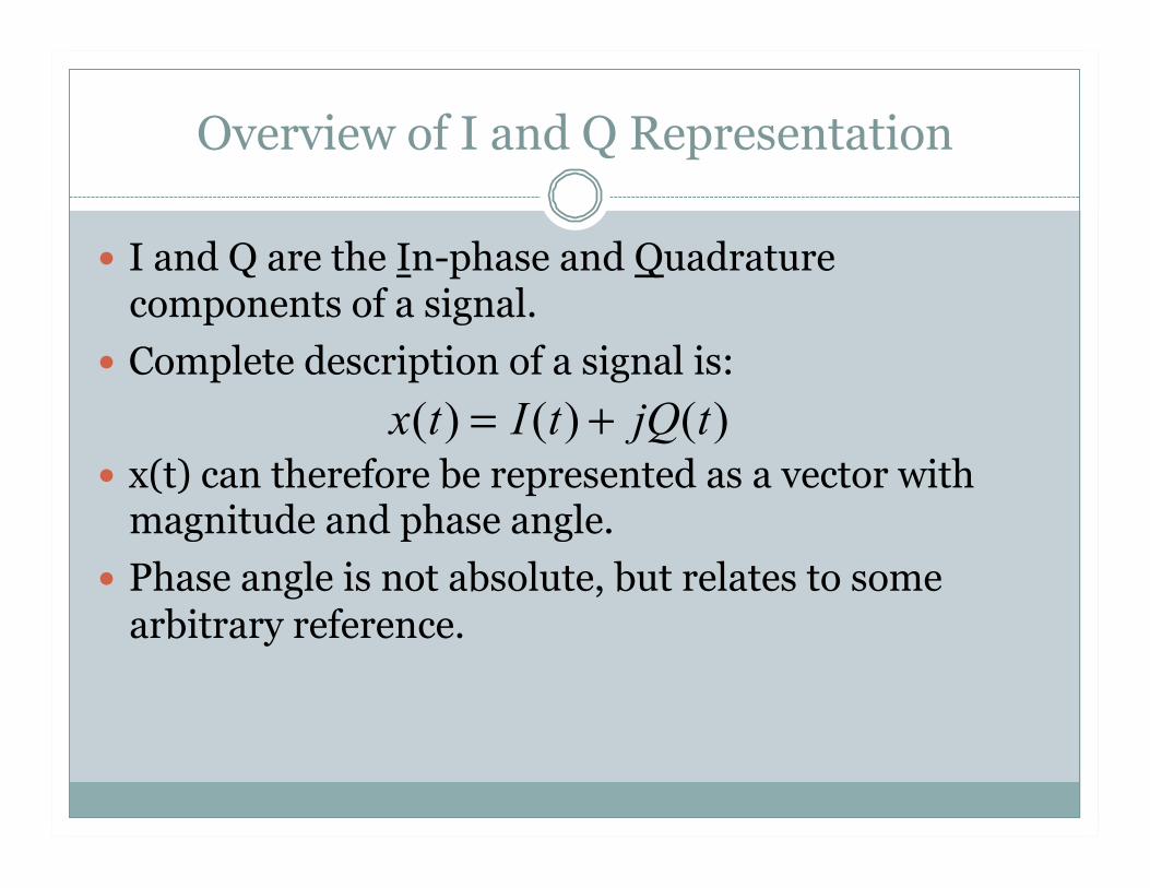
Overview of I and Q Representation
I and Q are the In-phase and Quadrature components of a signal.
Complete description of a signal is:
x(t) can therefore be represented as a vector with magnitude and phase angle.
Phase angle is not absolute, but relates to some arbitrary reference.
x(t) = I(t) + jQ(t)
Overview of I and Q Representation
In Digital Signal Processing (DSP), reference is local sampling rate.
DSP relies heavily on I and Q signals for processing. Use of I and Q allows for processing of signals near DC or zero frequency.

Overview of I and Q Representation
Nyquist frequency is twice highest frequency, not twice bandwidth of signal.
For example: common frequency used in analog signal processing is 455 kHz. To sample in digital processing, requires 910 kS/s. But bandwidth is only 10 kHz. With I & Q, sampling requires only 20 kS/s.
Overview of I and Q Representation
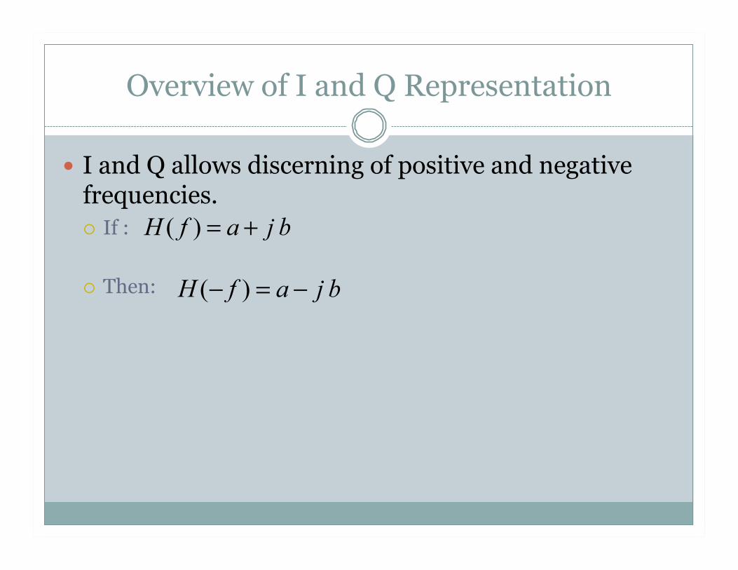
I and Q allows discerning of positive and negative frequencies. If :
Then:
Overview of I and Q Representation
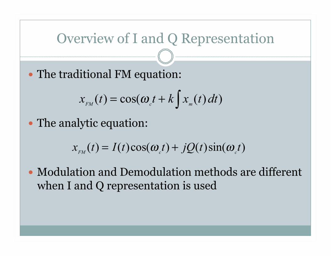
The traditional FM equation:
The analytic equation:
Modulation and Demodulation methods are different when I and Q representation is used
xFM (t) = cos(ω ct + k xm (t) dt)∫
xFM (t) = I(t)cos(ω ct) + jQ(t)sin(ω ct)
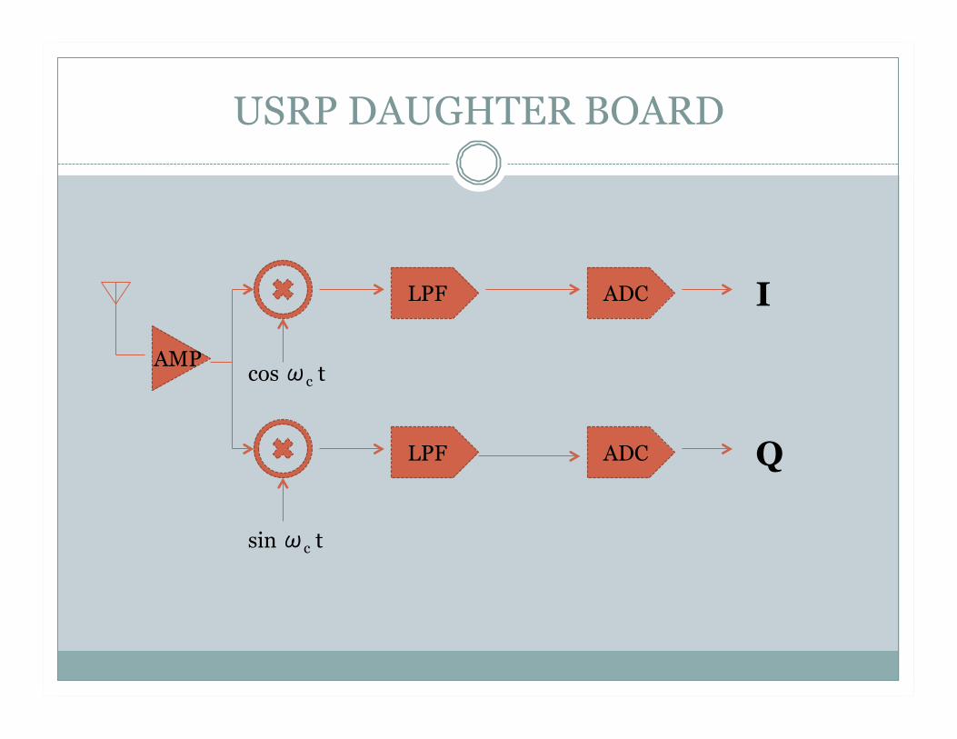
USRP DAUGHTER BOARD
I
Q
cos ωc t
sin ωc t
LPF
LPF
ADC
ADC
AMP
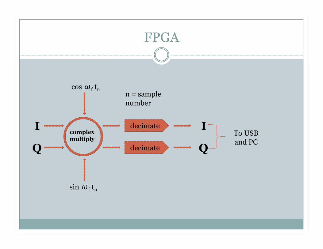
FPGA
I
Q
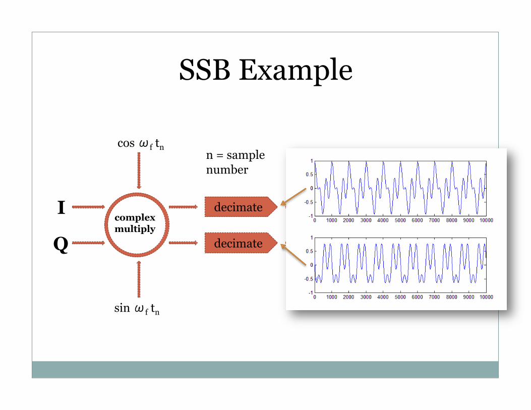
complex multiply
sin ωf tn
cos ωf tn
decimate
decimate
n = sample number
I
Q
To USB and PC
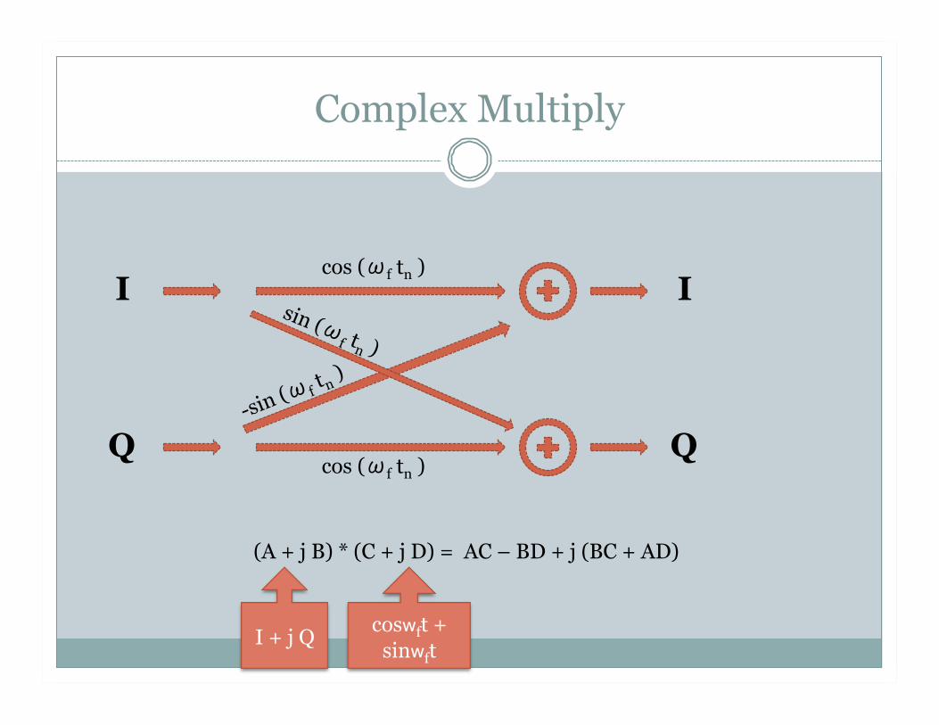
Complex Multiply
I
Q cos (ωf tn )
cos (ωf tn ) I
Q
(A + j B) * (C + j D) = AC – BD + j (BC + AD)
I + j Q coswft +
sinwft
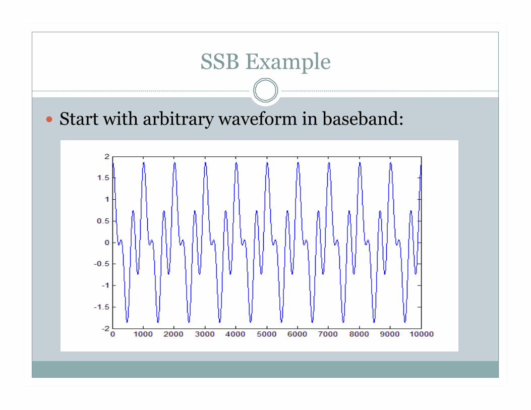
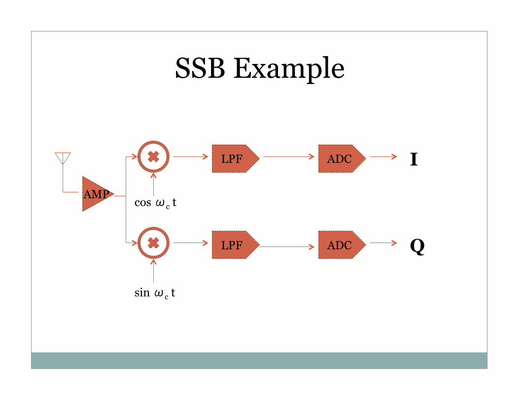
SSB Example
Start with arbitrary waveform in baseband:
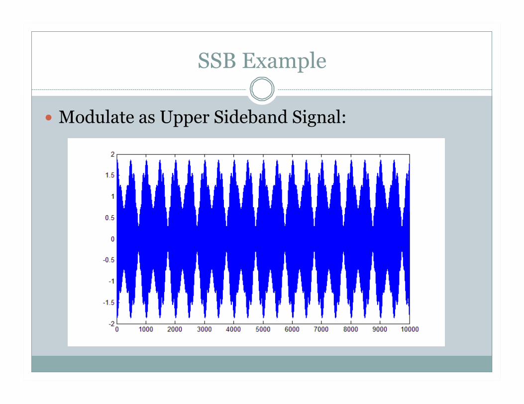
SSB Example
Modulate as Upper Sideband Signal:

SSB Example
I
Q
cos ωc t
sin ωc t
LPF
LPF
ADC
ADC
AMP
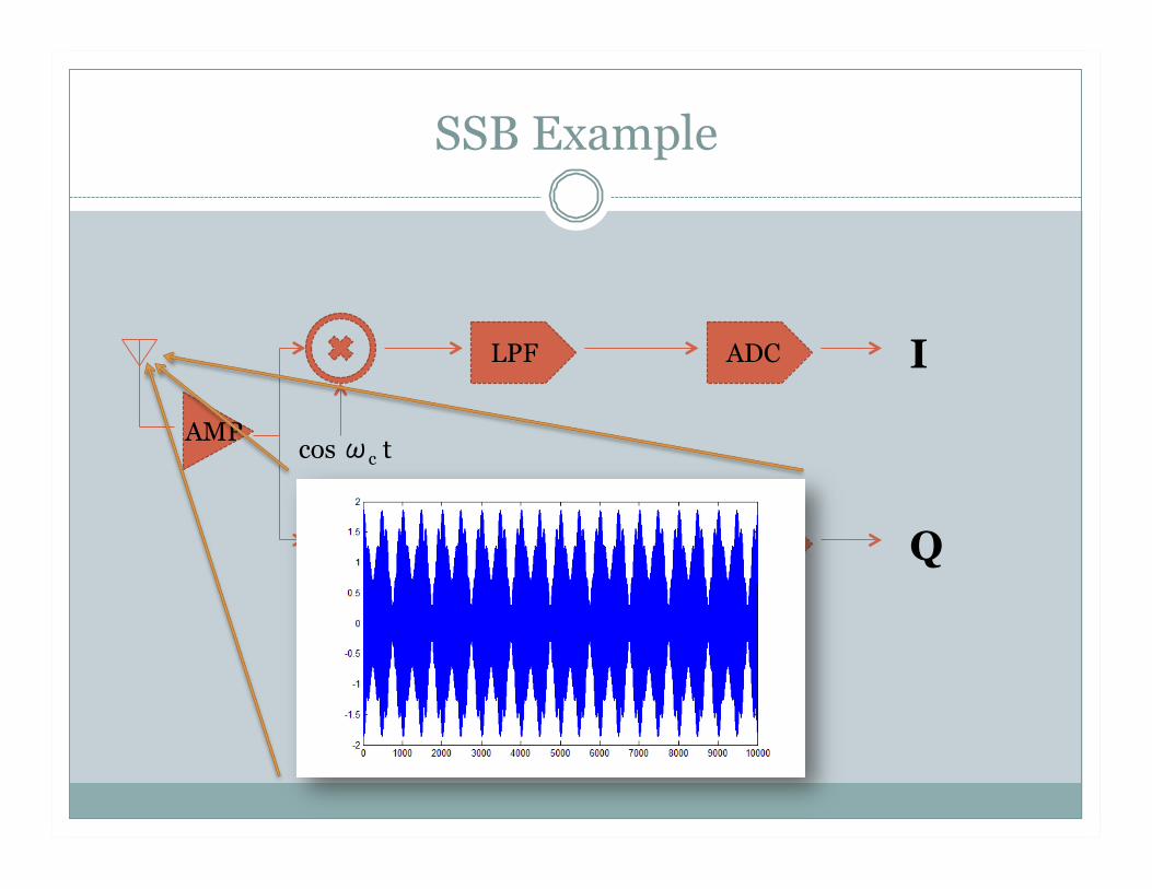
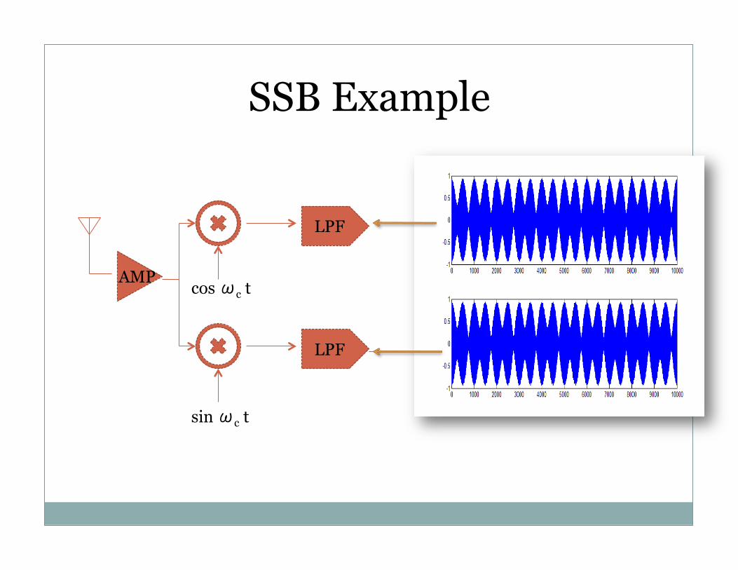
SSB Example
I
Q
cos ωc t
sin ωc t
LPF
LPF
ADC
ADC
AMP
SSB Example
I
Q
cos ωc t
sin ωc t
LPF
LPF
ADC
ADC
AMP
SSB Example
I
Q
cos ωc t
sin ωc t
LPF
LPF
ADC
ADC
AMP

SSB Example
I
Q
cos ωc t
sin ωc t
LPF
LPF
ADC
ADC
AMP

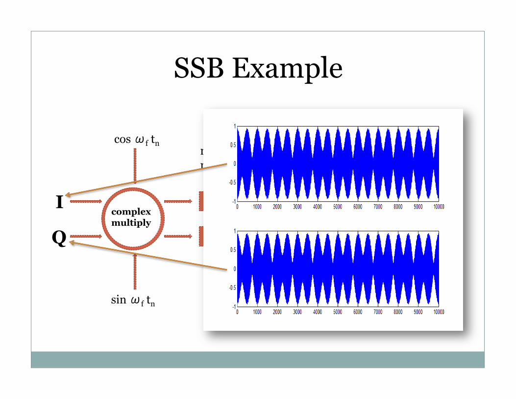
SSB Example
I
Q
complex multiply
sin ωf tn
cos ωf tn
decimate
decimate
n = sample number
I
Q
To USB and PC
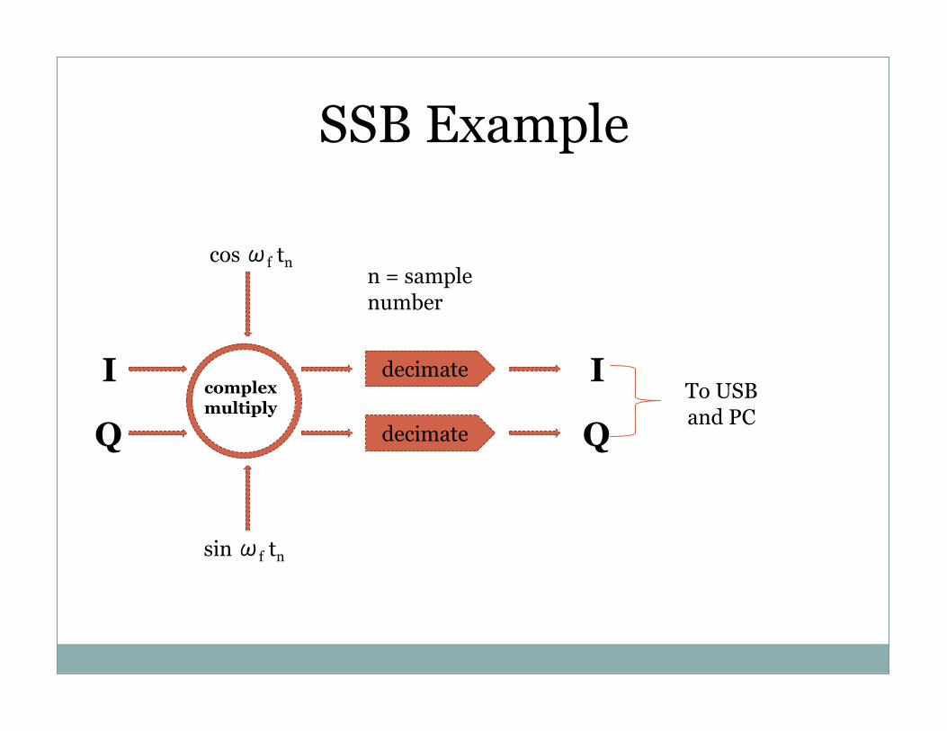
SSB Example
I
Q
complex multiply
sin ωf tn
cos ωf tn
decimate
decimate
n = sample number
I
Q
To USB and PC
SSB Example
I
Q
complex multiply
sin ωf tn
cos ωf tn
decimate
decimate
n = sample number
I
Q
To USB and PC
SSB Example
I
Q
complex multiply
sin ωf tn
cos ωf tn
decimate
decimate
n = sample number
I
Q
To USB and PC
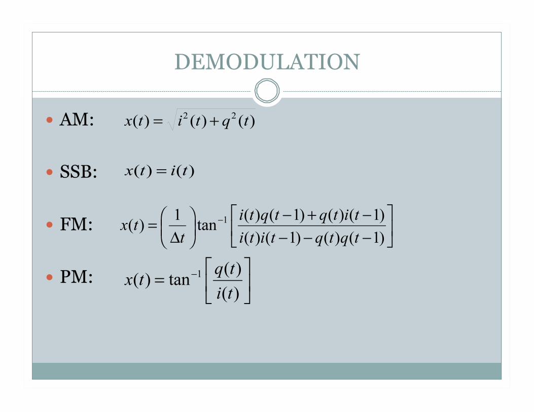
DEMODULATION
AM:
SSB:
FM:
PM:

Planning for Winter/Spring
The remainder of the Fall semester
Winter Break
Spring Meeting Time
Senior Project Overview