I 4 Ultimate Express Lanes System Engineering Management...
208
Interstate 4 Ultimate Managed Lanes System Engineering Management Plan 1 I-4 Ultimate Express Lanes System Engineering Management Plan FDOT D5 Approval Signature Date Rick Morrow FHWA Approval Signature Date Kris Milster
Transcript of I 4 Ultimate Express Lanes System Engineering Management...

Interstate 4 Ultimate Managed Lanes System Engineering Management Plan 1
I-4 Ultimate Express Lanes
System Engineering Management Plan
FDOT D5 Approval Signature Date
Rick Morrow
FHWA Approval Signature Date
Kris Milster

Interstate 4 Ultimate Managed Lanes System Engineering Management Plan 2
Table of Contents I-4 Ultimate Express Lanes ............................................................................................................. 1
System Engineering Management Plan .......................................................................................... 1
1 Executive Summary .............................................................................................................. 11
2 Purpose of Document ............................................................................................................ 11
3 Scope of Project .................................................................................................................... 11
3.1 Electronic Toll Collection .............................................................................................. 12
3.2 Congestion (Dynamic Tolling) Pricing System ............................................................. 12
3.3 Intelligent Transportation System (ITS) ........................................................................ 12
3.4 Overall Project Scope ..................................................................................................... 12
4 Technical Planning and Control............................................................................................ 14
4.1 Concept of Operations .................................................................................................... 15
4.2 Quality Management Plan Guidelines............................................................................ 16
4.3 System Development Plan Guidelines ........................................................................... 16
4.4 Data Security and Safety Plan Guidelines...................................................................... 16
4.5 Configuration Management Plan Guidelines ................................................................. 16
4.6 System Integration Plan Guidelines ............................................................................... 16
4.7 Verification (Test) Plan Guidelines................................................................................ 16
4.8 Deployment Plan Guidelines .......................................................................................... 17
4.9 Electronic Toll System Requirements ............................................................................ 17
4.10 Communications Management Plan............................................................................... 17
4.11 Procurement Management Plan ..................................................................................... 17
5 System Engineering Process ................................................................................................. 17
5.1 System Requirements Analysis ...................................................................................... 18
5.1.1 Sub-System Functional Analysis ............................................................................ 18
5.1.2 Design Synthesis ..................................................................................................... 18
5.1.3 System Analysis ...................................................................................................... 18
6 Transitioning Critical Technologies ..................................................................................... 19
7 Integration of the I-4 Ultimate Managed Lanes System ....................................................... 20
8 System Operations and Maintenance .................................................................................... 20

Interstate 4 Ultimate Managed Lanes System Engineering Management Plan 3
9 Conclusions ........................................................................................................................... 20
Appendix A: Abbreviations Used In This Document ................................................................... 21
Appendix B:Glossary of Terminology Used In The Plan ............................................................. 26
Appendix C: Documents Referenced ............................................................................................ 42
Appendix D: System Quality Management Plan Guidelines ........................................................ 43
1 General .................................................................................................................................. 44
2 Roles and Responsibilities .................................................................................................... 44
3 System Quality Policy........................................................................................................... 44
4 System Quality Management Organization .......................................................................... 45
4.1 Contractual Responsibility (FDOT D5) ......................................................................... 45
4.2 Project Consultant Staff ................................................................................................. 45
4.3 Integrator Systems Engineering Staff ............................................................................ 46
5 Quality Assurance and Control ............................................................................................. 46
5.1 Methodologies and Standards ........................................................................................ 46
5.2 Quality Assurance and Control ...................................................................................... 46
5.3 Quality Assurance and Control Milestones .................................................................... 46
5.4 System Integrator Controls ............................................................................................ 47
5.5 Design Control ............................................................................................................... 47
5.6 Document and Data Control ........................................................................................... 47
5.7 Purchasing Control ......................................................................................................... 47
5.8 Corrective Actions.......................................................................................................... 47
5.9 Quality Audits ................................................................................................................ 47
6 Typical Quality Assurance & Control Check List ................................................................ 49
Appendix E: System Development Plan Guidelines .................................................................... 50
1 General .................................................................................................................................. 51
2 Roles and Responsibilities .................................................................................................... 51
3 Program Management Document ......................................................................................... 51
3.1 Referenced Project Documents ...................................................................................... 51
3.2 Program Management Approach ................................................................................... 51
4 Program Management Implementation................................................................................. 52
4.1 FDOT D5 Program Responsibilities .............................................................................. 52
4.2 FDOT D5 Weekly Meetings .......................................................................................... 52

Interstate 4 Ultimate Managed Lanes System Engineering Management Plan 4
4.3 Key Contacts .................................................................................................................. 52
4.4 Integrator Project Schedule ............................................................................................ 52
4.5 Communications............................................................................................................. 53
4.6 Status Reporting ............................................................................................................. 53
5 On Site Installation ............................................................................................................... 53
6 I-4 Express Lanes System Testing ........................................................................................ 53
6.1 System Design and Development .................................................................................. 53
6.2 Work Breakdown Structure ............................................................................................ 53
6.3 Management Reporting And Monitoring ....................................................................... 54
6.4 I-4 Express Lanes Program Action Items ...................................................................... 54
6.5 System Configuration Management ............................................................................... 54
6.6 System Configuration Approval..................................................................................... 55
6.7 Subcontractor Control .................................................................................................... 55
6.8 integrator project schedule ............................................................................................. 55
6.9 Software development .................................................................................................... 55
7 Software Specification Development ................................................................................... 56
8 Preliminary and Detailed System Design ............................................................................. 58
9 Software Integration and Testing .......................................................................................... 59
9.1 Software Validation........................................................................................................ 59
9.2 Software Documentation ................................................................................................ 60
4.1 Software Documentation Control .................................................................................. 60
9.3 Process Versioning ......................................................................................................... 60
10 Conclusions ........................................................................................................................... 60
Appendix F: Data Security and Safety Plan Guidelines ............................................................... 61
1 General .................................................................................................................................. 62
2 Roles and Responsibilities .................................................................................................... 62
3 Data Security Engineering .................................................................................................... 62
3.1 System Engineering Consultant ..................................................................................... 62
3.2 Integrator Project Manager............................................................................................. 63
3.3 Data Security Engineering Process ................................................................................ 63
4 Scope ..................................................................................................................................... 63
5 Security Engineering Approach ............................................................................................ 64

Interstate 4 Ultimate Managed Lanes System Engineering Management Plan 5
5.1 Data Security Engineering Administration .................................................................... 65
5.1.1 Organizational Structure Overview ........................................................................ 65
5.1.2 Security Engineering Management ......................................................................... 65
5.1.3 Reviews ................................................................................................................... 65
5.1.4 Governance ............................................................................................................. 65
5.2 Data Security Engineering Process ................................................................................ 66
5.2.1 Standard Practices ................................................................................................... 66
5.2.2 Project-Specific Processes ...................................................................................... 66
5.2.3 Threat Analysis ....................................................................................................... 66
5.2.4 Identification ........................................................................................................... 66
5.2.5 Assessment of Threat Potentials ............................................................................. 67
5.2.6 Vulnerability Assessment ....................................................................................... 67
5.2.7 Identification ........................................................................................................... 67
5.2.8 Impact Assessment.................................................................................................. 68
5.2.9 Risk Analysis .......................................................................................................... 68
5.2.10 Countermeasure Design .......................................................................................... 68
5.2.11 Security Architecture .............................................................................................. 68
5.2.12 Candidate Trade Studies ......................................................................................... 69
5.2.13 Security Verification and Testing ........................................................................... 69
5.2.14 Assurance ................................................................................................................ 69
5.2.15 Evaluation ............................................................................................................... 69
Appendix G: Configuration Management Plan Guidelines .......................................................... 71
1 General .................................................................................................................................. 72
2 Roles and Responsibilities .................................................................................................... 72
2.1 FDOT D5........................................................................................................................ 72
2.2 Consultant Staff .............................................................................................................. 72
2.3 Integrator Systems Engineer(s) ...................................................................................... 73
3 Integration Activities ............................................................................................................ 73
3.1 Configuration Identification ........................................................................................... 75
3.2 Acquiring Configuration Items ...................................................................................... 77
3.3 Configuration Item Identification................................................................................... 77
3.4 Naming Configuration Items .......................................................................................... 77

Interstate 4 Ultimate Managed Lanes System Engineering Management Plan 6
3.5 Configuration Management Change Control ................................................................. 78
3.6 Request Change .............................................................................................................. 80
3.7 Evaluating Change ......................................................................................................... 80
3.8 Approve or Disapprove Change ..................................................................................... 80
3.9 Implement Change ......................................................................................................... 80
3.10 Status Tracking and Reporting ....................................................................................... 81
3.11 Configuration Audits ...................................................................................................... 82
3.12 Interface Controls ........................................................................................................... 84
3.13 Integrator Management .................................................................................................. 85
Appendix H: Risk Management Plan ........................................................................................... 88
1 Introduction ........................................................................................................................... 89
2 Risk Management Approach................................................................................................. 89
2.1 Risk Identification .......................................................................................................... 90
2.2 Expert Consultant Review .............................................................................................. 90
2.3 Risk Qualification and Prioritization.............................................................................. 90
2.4 Risk Monitoring ............................................................................................................. 91
2.5 Risk Mitigation and Avoidance...................................................................................... 91
2.6 Risk Register .................................................................................................................. 92
Appendix I: System Integration Plan Guidelines .......................................................................... 93
1 General .................................................................................................................................. 94
2 Roles and Responsibilities .................................................................................................... 94
2.7 FDOT D5 Personnel ....................................................................................................... 94
2.8 Project Consultant Staff ................................................................................................. 94
2.9 Integrator System Engineering Staff .............................................................................. 95
3 Integration Phases ................................................................................................................. 95
3.1 Field Sub-Systems Integration ....................................................................................... 96
3.2 FTE Tolls Back Office System Integration .................................................................... 97
3.3 Communications System Integration ............................................................................. 97
3.4 End-To-End Application Integration ............................................................................. 98
3.5 Integration Plan Components ......................................................................................... 98
3.6 Integration Activities ...................................................................................................... 98
3.7 Steps Related To Activities ............................................................................................ 99

Interstate 4 Ultimate Managed Lanes System Engineering Management Plan 7
3.7.1 Step Accomplishment ............................................................................................. 99
3.7.2 Resource Requirements .......................................................................................... 99
3.7.3 Key Integration Staff............................................................................................... 99
3.7.4 Criteria for Step Completion ................................................................................... 99
3.8 Integration Support ....................................................................................................... 100
3.9 Resources and their Allocation .................................................................................... 100
4 Training ............................................................................................................................... 100
5 Testing................................................................................................................................. 100
Appendix J: Verification (Test) Plan .......................................................................................... 101
1 General ................................................................................................................................ 102
2 Roles and Responsibilities .................................................................................................. 102
2.1 Florida Department of Transportation District 5 (FDOT D5) Staff ............................. 102
2.2 Project Consultant Staff ............................................................................................... 102
2.3 Integrator Systems Engineering Staff .......................................................................... 102
3 Test Plan.............................................................................................................................. 103
3.1 Equipment Environmental Testing............................................................................... 104
3.2 Factory Acceptance Test (FAT) ................................................................................... 104
3.3 On-Site Integration and Commissioning Test .............................................................. 105
3.4 Operational Performance Test (OPT) .......................................................................... 106
3.4.1 Severity 1 .............................................................................................................. 107
3.4.2 Severity 2 .............................................................................................................. 107
3.4.3 Severity 3 .............................................................................................................. 107
3.4.4 Severity 4 .............................................................................................................. 108
Appendix K: Deployment Plan Guidelines................................................................................. 109
1 General ................................................................................................................................ 110
2. Roles and Responsibilities .................................................................................................. 110
2.1. FDOT D5 Staff ............................................................................................................. 110
2.2. Project Consultant Staff ............................................................................................... 110
2.3. Integrator’s Engineering Staff ...................................................................................... 110
3. Purpose of Deployment Plan .............................................................................................. 111
4. System Deployment Staff ................................................................................................... 112
4.1. I-4 Ultimate Express Lanes Integrator ......................................................................... 112

Interstate 4 Ultimate Managed Lanes System Engineering Management Plan 8
4.2. Integrator Staff Qualifications ...................................................................................... 112
4.3. Integrator Management Support and Services ............................................................. 113
4.4. Integrator Project Manager........................................................................................... 113
4.5. Chief Technical Officer ................................................................................................ 113
4.6. Installation Manager ..................................................................................................... 114
4.7. Hardware Installation Engineer .................................................................................... 114
4.8. FTE Tolls Back Office Installation Engineer (Hardware and Software) ..................... 114
4.9. Roadside Equipment Software Support Engineer ........................................................ 115
4.10. Subcontractors .......................................................................................................... 115
4.11. Installation Equipment and Tools ............................................................................. 115
5. Electronic Toll System Documentation .............................................................................. 116
6. Installation Considerations.................................................................................................. 116
6.1. Installation Safety ......................................................................................................... 116
6.2. Code and Industry Standards ....................................................................................... 117
6.3. Installation Planning ..................................................................................................... 117
6.4. Weather And Productivity ............................................................................................ 117
6.5. Shop Drawing Submittals ............................................................................................ 117
6.6. Installation Daily Cleanup ............................................................................................ 117
7. System Testing and Acceptance ......................................................................................... 118
7.1. Operational Performance Test Records........................................................................ 118
7.2. Corrective Action ......................................................................................................... 118
7.3. Observation And Operational Performance Test Records ........................................... 118
7.4. Installation Schedule .................................................................................................... 119
8. Integrator Training .............................................................................................................. 119
8.1. FTE Tolls Back Office Supervisor staff:...................................................................... 119
8.2. FTE Tolls Back Office Customer Service Representative staff:.................................. 119
9. Conclusions ......................................................................................................................... 120
Appendix L: Electronic Tolling and Pricing Requirements ....................................................... 121
Appendix M: Communications Management Plan ..................................................................... 188
1 Introduction ......................................................................................................................... 189
2 Communications Management Approach........................................................................... 189
3 Communications Management Constraints ........................................................................ 190

Interstate 4 Ultimate Managed Lanes System Engineering Management Plan 9
4 Stakeholder Communication Requirements ....................................................................... 190
5 Roles ................................................................................................................................... 191
5.1 Project Sponsor – FDOT D5 District Secretary of Transportation .............................. 191
5.2 Program Manager – FDOT D5 .................................................................................... 191
5.3 Key Stakeholders – FTE, FDOT Central Office, FHWA, Selected Concessionaire
(Integrator) .............................................................................................................................. 191
5.4 Change Control Board .................................................................................................. 191
5.5 Customer ...................................................................................................................... 191
5.6 Project Manager ........................................................................................................... 191
5.7 Project Team ................................................................................................................ 192
5.8 Steering Committee ...................................................................................................... 192
5.9 Technical Lead ............................................................................................................. 192
6 Project Team Directory ....................................................................................................... 193
6.1 Communication Methods and Technologies ................................................................ 193
Communications Matrix ............................................................................................................. 195
7 Communication Flowchart.................................................................................................. 197
8 Guidelines for Meetings ...................................................................................................... 198
8.1 Meeting Agenda ........................................................................................................... 198
8.2 Meeting Minutes .......................................................................................................... 198
8.3 Action Items ................................................................................................................. 198
8.4 Meeting Chair Person ................................................................................................... 198
8.5 Note Taker .................................................................................................................... 198
8.6 Time Keeper ................................................................................................................. 198
8.7 Parking Lot ................................................................................................................... 198
9 Communication Standards .................................................................................................. 199
9.1 Kickoff Meeting ........................................................................................................... 199
9.2 Project Team Meetings................................................................................................. 199
9.3 Technical Design Meetings .......................................................................................... 199
9.4 Monthly Project Status Meetings ................................................................................. 199
9.5 Project Status Reports .................................................................................................. 199
10 Communication Escalation Process .................................................................................... 200
Appendix N: Procurement Management Plan ............................................................................ 201

Interstate 4 Ultimate Managed Lanes System Engineering Management Plan 10
1 Introduction ......................................................................................................................... 202
2 Procurement Management Approach ................................................................................. 202
3 Procurement Definition ....................................................................................................... 203
4 Type of Contract to be used ................................................................................................ 203
5 Procurement Risks .............................................................................................................. 204
6 Procurement Risk Management .......................................................................................... 204
7 Cost Determination ............................................................................................................. 204
8 Standardized Procurement Documentation ......................................................................... 205
9 Procurement Constraints ..................................................................................................... 206
9.1 Schedule: ...................................................................................................................... 206
9.2 Cost: ............................................................................................................................. 206
9.3 Scope: ........................................................................................................................... 206
9.4 Resources: .................................................................................................................... 206
9.5 Technology: .................................................................................................................. 206
10 Contract Approval Process ................................................................................................. 206
11 Decision Criteria ................................................................................................................. 207
12 Integrator Management ....................................................................................................... 207
13 Performance Metrics for Procurement Activities ............................................................... 208

Interstate 4 Ultimate Managed Lanes System Engineering Management Plan 11
1 Executive Summary This Systems Engineering Management Plan (SEMP) is a supplement the Project Management
Plan (PMP) [1], focusing on the system project management arrangements and system
engineering processes to be used for the project. It provides detail on systems engineering tasks,
particularly detailed information on the processes to be adopted to manage the special risk
associated with large, innovative system and software development projects.
Engineering tasks related to the development of custom software, or the adaption of existing
commercial systems, from requirements, through design implementation, integration, and
verification are very complex, and are new to many transportation engineers. This document and
associated documents have been developed as guidance for technical planning and control,
systems engineering process, transitioning critical technologies, and integration of the I-4
Ultimate Managed lanes System.
2 Purpose of Document The System Engineering Management Plan (SEMP) and associated documents have been
developed as guidelines to define the various technical planning and control, systems
engineering process, transitioning critical technologies, and integration of the I-4 Ultimate
Managed lanes System. The document will serve the following purposes:
• A repository for project technical plans
• Identification of items that are to be developed, delivered, integrated, installed, verified, and
supported
• Definition of when these tasks will be done, who will do them, and how the products will be
accepted and managed
• Definition of the technical processes to be used to produce each of the project’s products.
The intended readership of the document includes the following groups:
• FDOT Central Office
• FDOT D5
• FDOT Central Office
• FTE staff, consultants and integrators
• Project consultants
• The successful I-4 Ultimate Concessionaire (“Integrator”)
3 Scope of Project Detailed design and implementation of the I-4 Ultimate Managed lanes system will be the
contractual responsibility of FDOT D5 and conducted by a number of different organizations
under FDOT D5 direction. Detailed roles and responsibilities are defined in the I-4 Ultimate
Managed Lanes System Concept of Operations (ConOps), contained in a separate document. The
system consist of three primary elements

Interstate 4 Ultimate Managed Lanes System Engineering Management Plan 12
3.1 Electronic Toll Collection
This includes the roadside, telecommunications and back office facilities required to collect tolls
in a non-stop manner from relevant vehicles using the SunPass electronic toll collection system.
– the electronic toll collection system will be designed, implemented and operated under the
auspices of a Memorandum of Understanding (MOU) between FDOT D5 and FTE. This will
specify the services to be delivered by FTE and the relevant quality levels. It will also define
respective roles and responsibilities for each stage of the project. Roadway sensors on both the
general purpose and managed lanes are part of pricing and traffic management.
3.2 Congestion (Dynamic Tolling) Pricing System
The hardware and software required to determine the toll to be charges or each time period, each
road segment and each vehicle type on the I-4 Managed Lanes facility. The congestion pricing
system will support dynamic pricing to achieve demand management goals. The pricing system
will calculate toll rates based on prevailing traffic conditions. FDOT D5 will operate and manage
the congestion pricing system.
3.3 Intelligent Transportation System (ITS)
Consists of the regional traffic management center, field devices and telecommunications
infrastructure required to support traffic management, incident management and traveler
information. ITS (roadway sensors, telecommunications, dynamic message signs and CCTV that
are not part of the electronic toll collection and pricing system) will be designed, and
implemented under the auspices of a contract between FDOT D5 and a selected concessionaire
for the I-4 Ultimate project (Integrator).
3.4 Overall Project Scope
The concessionaire will be selected through a competitive public procurement process. The RFP
for the procurement will define requirements and guidance for system engineering for the
Concessionaire.
As it is desirable to have a single SEMP for the entire system, this document covers both Items 1
and 2. For simplicity, FTE, the FTE system integrator and the selected concessionaire are
referred to as the “Integrator” in the remainder of this document and Appendices.
The engineering process that will be implemented in support of the design, development, testing
and deployment of the I-4 Ultimate Managed lanes System will be important to ensure a
successful project. That engineering process is identified in this SEMP and the guidelines
presented in these documents will be conveyed to the selected I-4 Ultimate Managed lanes
System Integrator (Integrator) through the Request for Proposals (RFP), MOU and other
contract documents. The work of the selected Integrator will be monitored closely by FDOT D5
and consultants to ensure project success.

Interstate 4 Ultimate Managed Lanes System Engineering Management Plan 13
The I-4 Ultimate Managed lanes System will include the implementation of various
technologies, including Florida Statewide ETC system electronic tolling, vehicle detection,
system enforcement devices, and various types of telecommunications systems. An Integrator
will be selected to perform the I-4 Ultimate Managed lanes System design, development,
integration, testing and deployment. Florida Department of Transportation District 5 (FDOT D5)
will be responsible for ensuring that the delivered I-4 Ultimate Managed lanes System operates
according to the RFP and the other contract requirements. FDOT D5 will use consultants, FTE
resources and resources from the selected concessionaire to provide tolling system technical and
project monitoring assistance to ensure that the I-4 Ultimate Managed lanes System operates as
planned.
The scope of the I-4 Ultimate Managed lanes project was detailed in the draft Project
Management Plan (PMP) and is replicated here for convenience.
“1.2.1 Project Scope
Highway Improvements include the addition of lanes as described earlier, auxiliary lanes and
standard widths for the outside and inside shoulders. The project is more than a widening of
the road. While extra lanes of traffic will be added to help congestion and make way for the
expected growth, some benefits of the project are not so obvious, such as: geometric
improvements, operational ramp improvements, shoulder improvements, drainage upgrades
and bridge replacements.
The Ultimate Interstate 4 (I-4, SR 400) widening project will extend from West of Kirkman
Road in Orange County to East of SR 434 in Seminole County. I-4 will be reconstructed to
accommodate three (3) General Use Lanes (GUL), auxiliary lanes, and two (2) Managed
Lanes in the eastbound and westbound directions. Access to and from the Managed Lanes will
be provided through slip ramps located along the corridor and direct access Managed Lane-
only ramps at Grand National Drive, Anderson Street South Street, Ivanhoe Boulevard, and
Central Parkway interchanges.
The SR 408/I-4 interchange will be built to its ultimate configuration and will include
modifications to SR 408, which is operated by Orlando Orange County Expressway Authority
(OOCEA).
The widening of Interstate 4 includes reconstruction of the following interchanges:
• Kirkman Road
• Orange Blossom Trail (OBT)
• Michigan Avenue
• Kaley Street
• SR 408
• SR 50
• Ivanhoe Boulevard
• Princeton Street

Interstate 4 Ultimate Managed Lanes System Engineering Management Plan 14
• Par Avenue
• Fairbanks Avenue
• Lee Road
• Maitland Boulevard
• SR 436
• SR 434
A significant number of bridges that are part of Interstate 4 are being replaced within the
limits of the project.
Preliminary design (up to 60% design) has been completed on this twenty one (21) mile
corridor. These preliminary plans have established the I-4 mainline and ramp geometry based
on the traffic operational needs for the roadway. The plans also provide the beginning and
end transitions from the Managed Lanes to the existing General Use Lanes at the termini of
the project. But there have been modifications to the preliminary design for some of the
locations.
These modifications are:
• Revised Managed Lane exit flyover-ramp for the EB Maitland Boulevard exit
• Revised layout for Kirkman Interchange
• Grand National Drive Interchange with I-4
• Modifications to Managed Lane exits at South Street and Anderson Street and their adjoining
ramps
• Replacement of Shingle Creek Bridge over I-4
• Replacement of Westbound I-4 Bridge over Orange Blossom Trail (OBT)
• Central Parkway Managed Lane Interchange with I-4”
The project also provides for the planning, design, installation and operation of a sophisticated
open road tolling, dynamic pricing system and ITS system. This document addresses system
engineering processes and requirements associated with the electronic toll collection, pricing and
ITS systems.
4 Technical Planning and Control FDOT D5 will be responsible for ensuring that the I-4 Ultimate Managed lanes System is
properly designed, developed, integrated, tested and deployed. FDOT D5 shall use the services
of consultants and resources from the selected concessionaire (Integrator) to make sure that this
takes place. Even though the Integrator shall be contractually responsible to develop and closely
adhere to their own engineering practices, FDOT D5 and their consultants will have the
capability to review and approve the Integrator’s engineering practices and closely monitor these
activities to ensure full compliance of the various procedures.
It was determined that the best way to ensure successful system implementation was to develop a
set of system engineering guidelines that will be submitted to and discussed with the Integrator.
The Integrator will then be required to submit planning and design work consistent with the

Interstate 4 Ultimate Managed Lanes System Engineering Management Plan 15
guidelines. In order to convey to the Integrator the types of system engineering practices that
should be utilized, a number of SEMP documents have been developed as follows:
Concept of Operations
A. List of Abbreviations
B. List of Terminology
C. List of Referenced Documents
D. Quality Management Plan Guidelines;
E. System Development Plan Guidelines;
F. Data Security and Safety Plan Guidelines;
G. Configuration Management Plan Guidelines;
H. Risk Management Plan
I. System Integration Plan Guidelines;
J. Verification (Test) Plan Guidelines;
K. Deployment Plan Guidelines; and
L. Electronic Toll System Requirements.
M. Communications Management Plan
N. Procurement Management Plan
The Concept of Operations for the project has been developed a separate document and will be
submitted under separate cover.
As described above, the SEMP documents have been developed for use as guidelines defining
the technical planning and control, systems engineering process, transitioning critical
technologies, and integration of the I-4 Ultimate Managed lanes System. The development of
detailed plans for this engineering effort will be the responsibility of the chosen I-4 Ultimate
Managed lanes System Integrator.
Brief descriptions of each document are as follows:
4.1 Concept of Operations
Provides a high-level system operational overview of the I-4 Ultimate Managed lanes System
Project. This Plan describes the operating parameters of the I-4 Ultimate Managed lanes System,
defines which organization will be responsible for the I-4 Ultimate Managed lanes System
implementation, defines which group will construct the I-4 Ultimate Managed lanes
(Concessionaire), describes how the I-4 Ultimate Managed lanes System will be designed and
developed, defines the external interfaces to Florida’s Turnpike Enterprise (FTE), FDOT D5
Regional Traffic Management Center (RTMC) and the law enforcement agency. It also defines
roles and responsibilities for operations and maintenance.

Interstate 4 Ultimate Managed Lanes System Engineering Management Plan 16
4.2 Quality Management Plan Guidelines
Defines guidelines for the Integrator to ensure that all necessary quality assurance (QA) and
quality control (QC) processes are identified, maintained and adhered to by the Integrator. This is
in order to ensure that the delivered I-4 Ultimate Managed lanes System operates according to
the system performance requirements that are presented in the RFP and the other contract
documentation.
4.3 System Development Plan Guidelines
Provides details regarding how the Integrator will conduct the actual hardware and software
design, system development, shop testing, integration and factory testing of the I-4 Ultimate
Managed lanes System to ensure that it is designed and developed properly. These guidelines
will be used as the basis for the Integrator to develop a detailed I-4 Ultimate Managed lanes
System Development Plan, including management controls such as internal reviews, schedules,
requirements traceability matrix and Work Breakdown Structure (WBS).
4.4 Data Security and Safety Plan Guidelines
Defines data security measures to be incorporated into the I-4 Ultimate Managed lanes System.
The data security issue is of particular importance as the existing FDOT D5 telecommunication
network is shared with multiple agencies including education and health services as well as
transportation. This Plan will also identify the ways in which the system design, development
and deployment will be performed to ensure that the work is conducted in a safe manner.
4.5 Configuration Management Plan Guidelines
Defines guidelines on the I-4 Ultimate Managed lanes System configuration and how the
Integrator should develop, maintain and adhere to internal configuration management procedures
and processes. This is to ensure that system design and development enhancements and
modifications are carried out in a systematic manner that avoids unanticipated consequential
changes in system operation. This also ensures that all parties involved in deploying and
operating the system have a common understanding of the current system configuration.
4.6 System Integration Plan Guidelines
Defines how the equipment, subsystems and overall system will be integrated and tested by the
Integrator to ensure that a fully integrated and operating system is deployed. This ensures that all
of the functional requirements that are defined in the RFP and the other contract documents are
delivered. Both hardware and software integration and testing are addressed in this document.
4.7 Verification (Test) Plan Guidelines
Defines system testing and validation requirements that will be implemented by the Integrator.
This is to verify that the delivered I-4 Ultimate Managed lanes System features all of the system
requirements that are presented in the RFP and the other contract documents and that all features
are operating to the required specifications.

Interstate 4 Ultimate Managed Lanes System Engineering Management Plan 17
4.8 Deployment Plan Guidelines
Defines how the I-4 Ultimate Managed lanes System will be prepared for installation, how it will
be installed, tested and opened to traffic. The detailed equipment and software development,
integration testing and installation plans shall be provided by the Integrator as part of their
required documentation submittals.
4.9 Electronic Toll System Requirements
Defines the I-4 Ultimate Managed lanes System functional requirements, business operating
rules, and interfaces to other external systems. The I-4 Ultimate Managed lanes System
requirements shall be used by the Integrator as the basis for developing their proposal and to
effectively design develop and implement the new I-4 Ultimate Managed lanes System I-4
Ultimate Managed lanes System. Requirements have been coordinated with FTE Florida
Statewide ETC system requirements.
4.10 Communications Management Plan
Defines the communication requirements for the project and how information will be distributed.
This plan also identifies and defines the roles of people involved in project. It also includes a
communications matrix which maps the communication requirements of the project.
4.11 Procurement Management Plan
Defines the procurement requirements for the project and how it will be managed from
developing procurement documentation through contract closure.
The Integrator will also be responsible for the development of a comprehensive training plan.
The training plan will include all training activities as necessary, for the FTE Florida Statewide
ETC system™ customer service representatives and back office staff, FDOT D5 operations staff
and Regional Traffic Management Center staff, I-4 Ultimate Managed lanes System maintenance
technicians, and other operation staff. The training plan will be submitted for review and
approval by FDOT D5. This plan is discussed in more detail in the Deployment Plan.
5 System Engineering Process FDOT D5 will utilize a system engineering process that ensures that the Integrator develops and
closely adheres to a design process that is acceptable to FDOT D5. The design process approach
to be used on this Project is the federal approved V Model, which is described in this document,
Appendices and the Concept of Operations. The V Model System Engineering process addresses
systems planning, engineering, software development, integration testing, documentation
development, installation and deployment of the I-4 Ultimate Managed lanes System. FDOT D5
will utilize the services of consultants to ensure that this process is followed. Presented below
are the four areas of engineering analysis that will be implemented by FDOT D5:

Interstate 4 Ultimate Managed Lanes System Engineering Management Plan 18
5.1 System Requirements Analysis
The Concept of Operations document was used during the development of the various I-4
Ultimate Managed lanes functional requirements. FDOT D5 developed the system requirements
document in coordination with experienced tolling systems operation staff at FTE to obtain
important feedback and make certain that the requirements are closely coordinated with Florida
Statewide ETC system™ current and developing capabilities. The system requirements will be
provided to prospective Integrators as part of the I-4 Ultimate Managed lanes System RFP
package.
5.1.1 Sub-System Functional Analysis
As part of the system requirements development process, FDOT D5 consultants and the
Integrator will expand on the system requirements to the sub-system level. The consultants will
ensure there are no conflicts between the system and the sub-system related requirements. It is
expected that the various external interfaces, including to the FTE tolls back office, FDOT D5
RTMC, and the enforcement system equipment, will be identified at this point in the
requirements development process.
5.1.2 Design Synthesis
The Integrator will then use the various system and sub-system related functional requirements
as the basis for designing the I-4 Ultimate Managed lanes System. FDOT D5 and their
consultants shall closely oversee the Integrator’s design process and will conduct several rounds
of testing to ensure that all identified requirements are being met. It is envisioned that FDOT
D5’s consultants will utilize the comprehensive requirements trace matrix, which will be
developed by the Integrator, as the guide to ensure that the Integrator is designing the I-4
Ultimate Managed lanes System correctly.
5.1.3 System Analysis
During the Integrator’s I-4 Ultimate Managed lanes System design process, FDOT D5’s
consultants will monitor this activity to quickly identify possible technical problems with
proposed equipment, existing Florida Statewide ETC system™ hardware or software, and
Integrator application software. If technical trade-offs need to be implemented, the Integrator
shall follow these procedures, which will be clearly identified in the I-4 Ultimate Managed lanes
System RFP. FDOT D5 will be required to approve the requested technical trade-off as
proposed by the Integrator and recommended by the consultants.
FDOT D5 will develop and implement an internal document and drawing review and approval
process that will be applied to the systems engineering process of the I-4 Ultimate Managed
lanes System Project through system acceptance. FDOT D5’s District Secretary will have the
contractual and legal authority to sign off on all system engineering related aspects of the
Project. The typical approval process will be as described below:

Interstate 4 Ultimate Managed Lanes System Engineering Management Plan 19
1. The Integrator shall be required to provide a particular document and/or drawing within a
certain timeframe as will be stated in the I-4 Ultimate Managed lanes System RFP.
2. The District Secretary, or her designee, and FDOT D5’s consultants will carefully review and
provide comments and/or suggested modifications on the document or drawing. The
consultants will then compile all of the comments into a matrix/database.
3. The consultants will provide a recommendation to the District Secretary, which might be to
approve the document/drawing or ask the Integrator to make changes and re-submit the
document for a second round of review.
4. The District Secretary will then make the decision whether or not to officially approve the
document/drawing and will inform, in writing, the Integrator Project Manager/s of that
decision.
To enhance the ability for FDOT D5 to track the Integrator’s system engineering process, the
Integrator will be required to provide a document management tool. This tool will support
storage and retrieval of project documents, including correspondence and e-mail messages. The
program will also have the capability to segregate FDOT D5 documents from general project
documentation to be accessed exclusively by FDOT D5 and consultant staff. It is envisioned that
this system will be Cloud-based to allow the users to access the documents and files remotely to
facilitate the Integrator contract oversight task.
6 Transitioning Critical Technologies FDOT D5 and I-4 Ultimate Managed lanes System consultants are aware of the risks associated
with the potential technology transitioning process. Much time has been spent during the project
documentation development process to consider this important factor. Based on the specific
technology considerations for the I-4 Ultimate Managed lanes System Project, most of the
technologies to be incorporated into the I-4 Ultimate Managed lanes System are all very mature
and have been in successful operation for many years as part of the existing FTE Florida
Statewide ETC system™ program. These I-4 Ultimate Managed lanes System technologies
include the use of a Florida Statewide ETC system™ transponder detection process, vehicle
detection equipment, devices to determine vehicle travel times, tolling zone beacons, Closed
Circuit Television (CCTV) equipment, and DMS.
One of the I-4 Ultimate Managed lanes System technologies that will require detailed analysis is
the system enforcement equipment, which includes mobile enforcement readers (MERs) and
hand-held enforcement devices. Both of these pieces of equipment, and their associated
software, are currently in the early stages of use at other facilities. A procedure to deal with
possible technology swapping will be clearly identified in the I-4 Ultimate Managed Lanes
System RFP. FDOT D5 shall have approval rights for the technology transfer process and for
the technology that is ultimately chosen by the Integrator. FDOT D5’s consultants will be
involved in this process and will provide technology recommendations to FDOT D5.
Another challenge with respect to technology transitioning is the incorporation of emerging and
future technologies. The I-4 Ultimate project is a massive project involving the re-construction of
22 miles of limited access highway, including widening of the highway at approximately 130

Interstate 4 Ultimate Managed Lanes System Engineering Management Plan 20
bridge structures. Construction is expected to begin in 2014 with completion planned for 2020.
The system will therefore be launched in about 8 years’ time, allowing significant scope for
technology development between current planning efforts and system utilization. Foreseeable
technology changes and a process for incorporating disruptive technology developments will be
defined in the MOU between FDOT D5 and FTE and in the RFP.
7 Integration of the I-4 Ultimate Managed Lanes System The I-4 Ultimate Managed lanes System RFP and other contract documents will define system
integration requirements. The Integrator shall explain in the Integration Plan the methods that
will be used to ensure successful integration of the system components into a fully functioning I-
4 Ultimate Managed lanes System, fully addressing the requirements from the RFP and the other
Contract documents. The V-Model system engineering process steps shall be detailed and
adhered to by the Integrator during the design, integration, verification/testing, deployment and
training phases required to support the operation and maintenance of the new I-4 Ultimate
Managed lanes System I-4 Ultimate Managed lanes System. The Integrator shall provide written
confirmation that they will adhere to each of these engineering steps. FDOT D5 and their
consultants shall closely monitor the integration process to ensure that it is being performed
correctly.
8 System Operations and Maintenance System operations and maintenance requirements will be defined in the I-4 Ultimate Managed
lanes System RFP. The Integrator will be required to prepare and submit an Operations and
Maintenance Plan, which will be reviewed and approved by FDOT D5. The Integrator shall
explain in the Operations and Maintenance Plan the methods that will be used to operate and
maintain the I-4 Ultimate Managed lanes System consistent with the RFP and other contract
document requirements. This Plan will be adhered to by the Integrator who will be responsible
for I-4 Ultimate Managed lanes System operations and maintenance during the life of the
concession. FDOT D5 and consultants will closely monitor the operations and maintenance
effort to ensure that it is being performed correctly.
9 Conclusions The system engineering process that will be used during the I-4 Ultimate Managed lanes System
design, development, integration, testing and deployment phases of this project is critical to
ensure success. The processes identified herein will be described fully in the I-4 Ultimate RFP.
FDOT D5 and their consultants will ensure that the chosen Integrator adheres to the guidelines
and requirements that are presented in this SEMP and appendices.

Interstate 4 Ultimate Managed Lanes System Engineering Management Plan 21
Appendix A: Abbreviations Used In This Document

Interstate 4 Ultimate Managed Lanes System Engineering Management Plan 22
The following table contains a list of all the abbreviations used in the various plan documents
and Appendices, along with an explanation of the abbreviation.
Abbreviation Explanation
24/7 24 hours per day, 7 days per week
CCTV Closed Circuit Television Camera
CERT United States Computer Emergency Readiness Team
CI Configurable Item
CM Configuration Management
CMP Configuration Management Plan
ConOps Concept of Operations
COTS Commercial Off The Shelf
CSR Customer Service Representative
CTO Chief Technology Officer
DDD Detailed Design Document
DDR Detailed Design Review
DMS Dynamic Message Sign
DoS Denial of Service
EB East Bound
ETC Electronic Toll Collection
FAT Factory Acceptance Test
FDOT Florida Department of Transportation
FDOT Central Office Florida Department of Transportation Central Office

Interstate 4 Ultimate Managed Lanes System Engineering Management Plan 23
Abbreviation Explanation
FDOT D5 Florida Department of Transportation District 5
FHWA Federal Highway Administration
FTE Florida’s Turnpike Enterprise
GUL General Use Lane
I-4 Interstate 4
ISO International Standards Organization
IT Information Technology
ITS Intelligent Transportation Systems
MER Mobile Enforcement Reader
MOMS Maintenance Online Management System
MOU Memorandum of Understanding
MS Microsoft
OBT Orange Blossom Trail
OICT On-site Integration and Commissioning Test
OOCEA Orlando-Orange County Expressway Authority
OPT Operational Performance Test
OS Operating System
PCI Payment Card Industry (standard)
PDD Preliminary Design Document
PDF Portable Document Format (Adobe Acrobat)
PDR Preliminary Design Review

Interstate 4 Ultimate Managed Lanes System Engineering Management Plan 24
Abbreviation Explanation
PERT Project Evaluation and Review Technique
PIP Project Installation Plan
PM Project Manager
PMD Program Management Document
PMO Project Management Office
PMP Project Management Plan
PQM Project Quality Manager
QA Quality Assurance
QC Quality Control
QM Quality Management
QMP Quality Management Plan
RCSC Regional Customer Service Center
RFP Request for Proposals
RTMC Regional Traffic Management Center
SANS SysAdmin, Audit, Network, and Security
SDP System Development Plan
SEMP System Engineering Management Plan
SSD Software Specification Document
SVP System Verification (Test) Plan
VDS Vehicle Detection System
WBS Work Breakdown Structure

Interstate 4 Ultimate Managed Lanes System Engineering Management Plan 25

Interstate 4 Ultimate Managed Lanes System Engineering Management Plan 26
Appendix B:Glossary of Terminology Used In The Plan
Interstate 4 Ultimate Managed Lanes System Engineering Management Plan 27
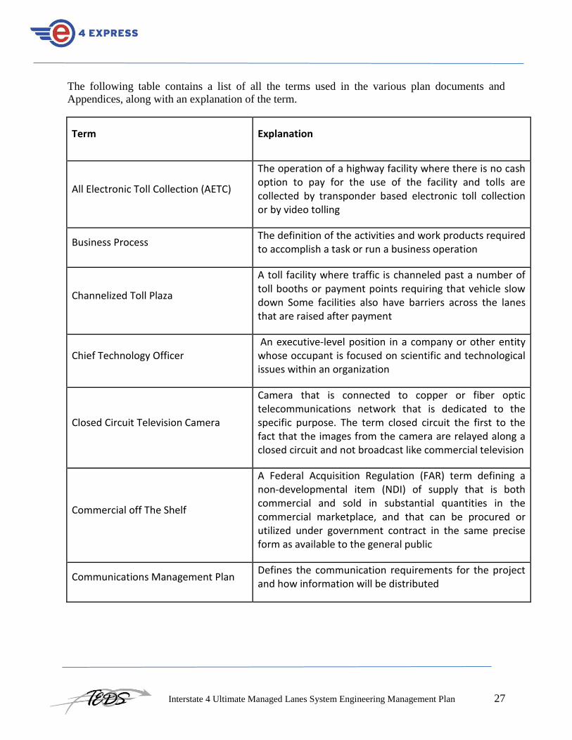
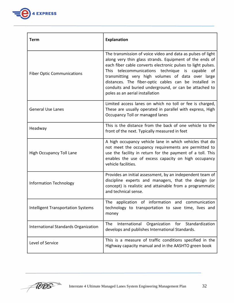
The following table contains a list of all the terms used in the various plan documents and
Appendices, along with an explanation of the term.
Term Explanation
All Electronic Toll Collection (AETC)
The operation of a highway facility where there is no cash option to pay for the use of the facility and tolls are collected by transponder based electronic toll collection or by video tolling
Business Process The definition of the activities and work products required to accomplish a task or run a business operation
Channelized Toll Plaza
A toll facility where traffic is channeled past a number of toll booths or payment points requiring that vehicle slow down Some facilities also have barriers across the lanes that are raised after payment
Chief Technology Officer An executive-level position in a company or other entity whose occupant is focused on scientific and technological issues within an organization
Closed Circuit Television Camera
Camera that is connected to copper or fiber optic telecommunications network that is dedicated to the specific purpose. The term closed circuit the first to the fact that the images from the camera are relayed along a closed circuit and not broadcast like commercial television
Commercial off The Shelf
A Federal Acquisition Regulation (FAR) term defining a non-developmental item (NDI) of supply that is both commercial and sold in substantial quantities in the commercial marketplace, and that can be procured or utilized under government contract in the same precise form as available to the general public
Communications Management Plan Defines the communication requirements for the project and how information will be distributed

Interstate 4 Ultimate Managed Lanes System Engineering Management Plan 28
Term Explanation
Communications Management Plan
Portion of the overall Project Management Plan which details how project communications will be conducted, who will participate in communications, frequency of communications, and methods of communications
Concept of Operations
Is a document describing the characteristics of a proposed system from the viewpoint of an individual who will use that system. It is used to communicate the quantitative and qualitative system characteristics to all stakeholders
Configurable Item The fundamental structural unit of a configuration management system
Configuration Management
Arrangements for establishing and maintaining the integrity and control of software/hardware products and documents supplied by the Integrator during the life cycle of the I-4 Ultimate Express Lanes Toll Collection, Pricing and Intelligent Transportation Systems
Configuration Management Plan Guidelines
Defines arrangements for establishing and maintaining the integrity and control of software/hardware products and documents supplied by the Integrator during the life cycle of the I-4 Ultimate Express Lanes Toll Collection, Pricing and Intelligent Transportation Systems. This document provides guidelines for the creation of the Configuration Management Plan by the Integrator
Congestion Pricing Dynamic tolling implemented to achieve a level of service objectives by taking advantage of the relationship between trip cost and traffic volume
Customer Service Representative Customer facing staff in the SunPass Customer Service Center

Interstate 4 Ultimate Managed Lanes System Engineering Management Plan 29
Term Explanation
Data Security and Safety Plan Guidelines
Describes the tools, processes, and methods required to design, implement, and test the electronic toll collection, pricing and ITS to ensure that it remains dependable once deployed. In the context of the I-4 Ultimate Express Lanes Project, it is also to ensure that the management and monitoring of the related transportation infrastructure continues unimpeded. This document provides guidelines for the creation of the Data Security and Safety Plan by the Integrator
Dedicated Short Range Communications (DSRC)
Relatively short range communications in the 914 mhz or 5.8 ghz band range used to communicate between the vehicle and roadside equipment for Electronic Toll Collection
Denial of Service
An attempt to make a machine or network resource unavailable to its intended users. Although the means to carry out, motives for, and targets of a dos attack may vary, it generally consists of the efforts of one or more people to temporarily or indefinitely interrupt or suspend services of a host connected to the internet
Deployment Plan Guidelines
Provides the details of the planned installation of the I-4 Ultimate Express Lanes I-4 roadside, FTE, Regional Traffic Management Center, and system enforcement equipment and subsystems. This document provides guidelines for the creation of the Deployment Plan by the Integrator
Detailed Design Document
A detailed written description of a system, that a system designer writes in order to give a development team an overall guidance of the architecture of the software project. Usually accompanies an architecture diagram with pointers to detailed feature specifications of smaller pieces of the design. Practically, a design document is required to coordinate a large team under a single vision

Interstate 4 Ultimate Managed Lanes System Engineering Management Plan 30
Term Explanation
Detailed Design Review
Provides an in-depth assessment, by an independent team of discipline experts and managers, that the design (or concept) is realistic and attainable from a programmatic and technical sense
Digital Video Recorder (DVR)
A device that stores video images in digital form on either a hard disk or solid-state memory. It also has an operating system that allows the storage of the images to be managed and selected images retrieved as required. For dynamic tolling applications this device would be integrated into a larger system
Dynamic Message Sign (DMS)
Often referred to as variable message signs or changeable message signs. These are roadside devices that display configurable messages to drivers. They are typically connected to a fiber-optic telecommunications network to a traffic management center. An operator at the traffic management center can input the message and have it displayed on one or more roadside dynamic message signs. For dynamic tolling purposes this technology is used to communicate the prevailing toll for each segment of road to the drivers. They are typically placed sufficiently far in advance of the decision point in the network that the driver can see the message and then take a decision on the basis of the tolling information
Dynamic Pricing
A pricing structure in which charges are regularly adjusted according to traffic conditions to maintain a free-flowing level of traffic, increasing when the lanes are relatively full and decreasing when the lanes have extra capacity. Traffic sensors on the road facility being managed and sometime on parallel routes are used to continually monitor the traffic conditions
Dynamic Tolling Use of traffic sensors and electronic toll collection technology (open road) to vary the price for using a road facility at regular intervals

Interstate 4 Ultimate Managed Lanes System Engineering Management Plan 31
Term Explanation
Elasticity of demand The change in demand divided by the change in price for a commodity
electronic payment system
A system that has been designed and implemented to enable cash free payment for good s and services using payment device, reader, telecommunications and back office technologies
Electronic Toll Collection (ETC) Electronic systems that collect tolls, eliminating the need for tollbooths and for vehicles to stop to make payment.
Electronic Toll System Requirements
The needs or conditions to be met for Electronic Toll Collection on the I-4 Ultimate Project, taking account of the possibly conflicting requirements of the various stakeholders
Escalation The process which details how conflicts and issues will be passed up the management chain for resolution as well as the timeframe to achieve resolution
Express Lane A limited access road facility where users pay a fee for the use of the facility or qualify for free use due to the number of occupants in the vehicle
Factory Acceptance Test
Before delivery or final installation checks are made to be certain that equipment or plant has been completed to the required quality and is fully operational. A factory acceptance test determines whether equipment or plant operates as intended and meets all contractual specifications
Federal Highway Administration Is a division of the United States Department of Transportation that specializes in highway transportation
Interstate 4 Ultimate Managed Lanes System Engineering Management Plan 32
Term Explanation
Fiber Optic Communications
The transmission of voice video and data as pulses of light along very thin glass strands. Equipment of the ends of each fiber cable converts electronic pulses to light pulses. This telecommunications technique is capable of transmitting very high volumes of data over large distances. The fiber-optic cables can be installed in conduits and buried underground, or can be attached to poles as an aerial installation
General Use Lanes Limited access lanes on which no toll or fee is charged, These are usually operated in parallel with express, High Occupancy Toll or managed lanes
Headway This is the distance from the back of one vehicle to the front of the next. Typically measured in feet
High Occupancy Toll Lane
A high occupancy vehicle lane in which vehicles that do not meet the occupancy requirements are permitted to use the facility in return for the payment of a toll. This enables the use of excess capacity on high occupancy vehicle facilities.
Information Technology
Provides an initial assessment, by an independent team of discipline experts and managers, that the design (or concept) is realistic and attainable from a programmatic and technical sense.
Intelligent Transportation Systems The application of information and communication technology to transportation to save time, lives and money
International Standards Organization The International Organization for Standardization develops and publishes International Standards.
Level of Service This is a measure of traffic conditions specified in the Highway capacity manual and in the AASHTO green book

Interstate 4 Ultimate Managed Lanes System Engineering Management Plan 33
Term Explanation
Limited Access Highway
A limited-access road known by various terms worldwide, including limited-access highway, dual-carriageway and expressway, is a highway or arterial road for high-speed traffic which has many or most characteristics of a controlled-access highway (freeway or motorway), including limited or no access to adjacent property, some degree of separation of opposing traffic flow, use of grade separated interchanges to some extent, prohibition of some modes of transport such as bicycles or horses and very few or no intersecting cross-streets
Managed Lane(s) A lane or lanes that are used to increase roadway efficiency through management of operations and access
Maximum toll
This is a maximum amount in dollars or cents that will be charged for a trip along the dynamic tolling facility. It is often specified in terms of a Per mile charge. For example One dollar per mile
Memorandum of Understanding
A document describing a bilateral or multilateral agreement between two or more than two parties. It expresses a convergence of will between the parties, indicating an intended common line of action
Minimum toll
This is a minimum amount in dollars or cents that will be charged for a trip along the dynamic tolling facility. It is often specified in terms of a Per mile charge. For example $.25 per mile
Mobile Enforcement Reader
Includes an antenna, a reader coupled to receive signals from the antenna and a control/display unit (CDU) coupled to the reader. The CDU selects a receive direction and processes signals provided thereto from the reader. When the MER and a transponder are in proximity, the MER interrogates the transponder and receives information related to toll payment

Interstate 4 Ultimate Managed Lanes System Engineering Management Plan 34
Term Explanation
Non-cash transactions Payment for goods or services by means other than cash. Such as credit cards, debit cards, PayPal or special purpose payment systems for transportation
Non-stop tolling The collection of tolls or fees at normal road operating speeds
Onsite Integration and Commissioning Test
Equipment, subsystem and system-wide testing of the Managed Lanes System. The purpose is to provide both the Integrator and FDOT D5 a mechanism for verifying and documenting successful system performance throughout the installation process up to the point of approval to commission the lanes
Open Road Tolling (Open Road Tolling)
Electronic toll collection using overhead gantries and no traffic channelization
Operational Performance Test
The final phase of testing of the I-4 Ultimate Express Lanes System. This test shall serve to closely monitor the performance of the managed lanes under live traffic operating conditions once the managed lanes are open to toll-paying vehicles
Orlando-Orange County Expressway Authority
A toll road operating agency in Central Florida that implements and operates an expressway system that improves the mobility and quality of life in Central Florida and provides access to major economic centers consistent with growth management and environmental objectives, accomplishing this in a manner which is financially sound and cooperative with other modes of transportation and governmental jurisdictions
Payment Cards Industry Standard (PCI)
A data security standard for payment systems data developed by the credit card industry
Portable Document Format (Adobe Acrobat)
A file format used to represent documents in a manner independent of application software, hardware, and

Interstate 4 Ultimate Managed Lanes System Engineering Management Plan 35
Term Explanation
operating systems
Preliminary Design Document
A preliminary version of a written description of a system, that a system designer writes in order to give a development team an overall guidance of the architecture of the software project. Usually accompanies an architecture diagram with pointers to detailed feature specifications of smaller pieces of the design
Preliminary Design Review
Provides an in-depth assessment, by an independent team of discipline experts and managers, that the design (or concept) is realistic and attainable from a programmatic and technical sense
Prepaid Toll Account A special purpose account that contains funds that are deducted to paying tolls. Funds are paid in by cash at a service center or transferred from the drivers credit card
Pre-published toll schedule A schedule of toll rates that specifies the toll for a specific day, time of day, segment of Highway and class of vehicle
Procurement Management Plan
Defines the procurement requirements for the I-4 Managed Lanes Project and how it will be managed from developing procurement documentation through contract closure
Program Management Document Defines and describes the arrangements and activities to be supported in order to effectively manage work, schedule and budget for the project
Project Evaluation and Review Technique
A statistical tool, used in project management that is designed to analyze and represent the tasks involved in completing a given project
Project Management Office A group or department within a project that defines and maintains standards for project management within the project

Interstate 4 Ultimate Managed Lanes System Engineering Management Plan 36
Term Explanation
Project Management Plan
A project management plan is the planning document, capturing the entire project end-to-end, covering all project phases, from initiation through planning, execution and closure
Project Manager A professional in the field of project management. Project managers can have the responsibility for the planning, execution and closing of any project
Project Quality Manager A professional in the field of quality management. Project quality managers can have the responsibility for planning and executing project quality activities
Quality Assurance A program for the systematic monitoring and evaluation of the various aspects of a project, service, or facility to ensure that standards of quality are being met
Quality Control An aggregate of activities (as design analysis and inspection for defects) designed to ensure adequate quality especially in manufactured products
Quality Management Activities (as design analysis and inspection for defects) designed to ensure adequate quality especially in manufactured products
Regional Traffic Management Center The FDOT D5 traffic management facility that has responsibility for Central Florida Region traffic management.
Request for Proposals Procurement document that defines what the client requires and how proposals should be structured and formatted
Revenue generation
A dynamic tolling of pricing technique while the specific objective is to maximize the amount of revenue being collected by the tolling system. This money is reinvested into transportation network

Interstate 4 Ultimate Managed Lanes System Engineering Management Plan 37
Term Explanation
Risk Management Plan
Explains why risks exist and highlights the purpose and importance of risk management. It provides a general description of why risk management is essential to effectively managing the I-4 Ultimate Toll Collection and ITS system and describes what is needed before risk management can begin
Software Specification Document
A requirements specification for a software system is a complete description of the behavior of a system to be developed and may include a set of use cases that describe interactions the users will have with the software. In addition it also contains non-functional requirements. Non-functional requirements impose constraints on the design or implementation (such as performance engineering requirements, quality standards, or design constraints)
Speed This is the average velocity of a sample of vehicles passing a specified point in the highway. It would be more accurately described as time mean speed
Stakeholder Individuals or groups involved in the project or whose interests may be affected by the project’s execution or outcome
Sticker Tag An ISO 18000 6C standard paper tag used for vehicle identification in Electronic Toll Collection
SunPass Customer Service Center Call center that is equipped to handle large amounts of customer telephone requests regarding sunpass in addition to handling other customer communications
SysAdmin, Audit, Network, and Security
SANS is the most trusted and by far the largest source for information security training and security certification in the world. It also develops, maintains, and makes available at no cost, the largest collection of research documents about various aspects of information security,

Interstate 4 Ultimate Managed Lanes System Engineering Management Plan 38
Term Explanation
and it operates the Internet's early warning system
System Development Plan Guidelines
Describes the methodology required to ensure that the I-4 Express Lanes system development work is conducted efficiently and effectively. The System Development Plan, to be based on these guidelines will also include the Integrator’s approach to managing the project and planned software development and integration processes. This document provides guidelines for the creation of the System Development Plan by the Integrator
System Engineering Management Plan
A supplement the Project Management Plan (PMP), focusing on the technical project management arrangements and system engineering processes to be used for the project. It provides detail on systems engineering tasks, particularly detailed information on the processes to be adopted to manage the special risk associated with large, innovative system and software development projects
System Integration Plan Guidelines
Define the activities necessary to integrate the I-4 Ultimate Managed Lanes functional software components into the I-4 Ultimate Managed Lanes software application system. The Integration Plan, to be developed by the Integrator on the basis of these guidelines shall contain an overview of the system, a description of the major tasks involved in the integration, including the overall Integrator resources that are needed to fully support the integration effort. This document provides guidelines for the creation of the System Integration Plan by the Integrator. This document provides guidelines for the creation of the Quality Management Plan by the Integrator

Interstate 4 Ultimate Managed Lanes System Engineering Management Plan 39
Term Explanation
System Quality Management Plan
Defines the activities involved in the systematic monitoring and evaluation of the various aspects of a project, service, or facility to ensure that standards of quality are being met
System Quality Management Plan Guidelines –
Defines in outline the activities involved in the systematic monitoring and evaluation of the various aspects of a project, service, or facility to ensure that standards of quality are being met. Forms the basis for the concessionaire to develop the Quality Management Plan
Time-of-Day Pricing Facility charges that vary by time of day, with charges generally higher during peak periods and lower other times
Toll adjustment interval
In dynamic tolling and you toll rate is calculated at regular intervals based on traffic conditions. The toll adjustment interval is the time in minutes between each toll calculation
Toll by Plate or Video Tolling
The use of CCTV cameras and advanced image processing to read vehicle license plates, match the license number to a driver and vehicle licensing database and deduct a toll from a pre=paid account or automatically send a bill
Toll Operating Mode
Dynamic tolling systems May required to work in more than one toll operating mode. For example there may be three possible operating modes for a dynamic tolling system. The first mode would be normal routine operation. The second mode would be for evacuation management in which case the tolls on the whole facility would be reduced to zero for a specified period of time. The third mode would be for incident management where the toll is removed because the express lanes facility is blocked or partially blocked because of a traffic incident

Interstate 4 Ultimate Managed Lanes System Engineering Management Plan 40
Term Explanation
Traffic flow density The number of vehicles present at any given time within a specific period of road. This could be measured as vehicles per kilometer or vehicles per lane per kilometer
Traffic volume or flow The number of vehicles passing a given point in the highway over a specified period of time. Often measured in vehicles per hour
Transaction The process through which goods and services are paid for by an exchange of funds from buyer to seller
Transponder
An electronic tag mounted on a license plate, built into a vehicle, or placed on the windshield or dashboard by which drivers can be charged a fee (or toll) without stopping
United States Computer Emergency Readiness Team
The 24-hour operational arm of the United States' Department of Homeland Security's National Cybersecurity and Communications Integration Center (NCCIC). The United States Computer Emergency Readiness Team (US-CERT) leads efforts to improve the nation's cybersecurity posture, coordinate cyber information sharing, and proactively manage cyber risks to the Nation while protecting the constitutional rights of Americans
V Model System engineering methodology specified by FHWA
Value Pricing
Adoption of market principles routinely used in the private sector to bring transportation supply and demand into balance. An example is a system of fees or tolls paid by drivers to gain access to certain roadway facilities providing consistent, free-flowing service compared to the alternative toll-free facilities

Interstate 4 Ultimate Managed Lanes System Engineering Management Plan 41
Term Explanation
Dynamic tolling algorithm
This is a process that is conducted to calculate toll amounts related to varying traffic conditions. It is often used to describe the software program used to do the toll calculations, but more accurately it refers to the defined process which the software executes
Vehicle Detection System
A roadside device that is capable of measuring one or more parameters associated with the traffic passing the device location. These parameters could include vehicle speed, headway, and vehicle classification. There are several alternative technologies that can be used for these sensors. These include microwave, inductive loop and video image processing
Verification (Test) Plan Guidelines
Presents the I-4 Ultimate Express Lanes equipment and system verification testing process. It outlines the different types of tests that shall be conducted and identifies the roles and responsibilities of each group that will be working on this project. This document provides guidelines for the creation of the Verification (Test) Plan by the Integrator
Work Breakdown Structure Serves as a guide for defining work as it relates to a specific project's objectives

Interstate 4 Ultimate Managed Lanes System Engineering Management Plan 42
Appendix C: Documents Referenced
[1] I-4 Ultimate Draft Project Management Plan (PMP)
[2] http://en.wikipedia.org/wiki/ISO_9000 - Retrieved February 21, 2013
[3] Payment Card Industry Standard. PCI Standard Definition Retrieved From:
http://en.wikipedia.org/wiki/Payment_Card_Industry_Data_Security_Standard - On January 31,
2013. Note that PCI Official Web Site is: https://www.pcisecuritystandards.org/

Interstate 4 Ultimate Managed Lanes System Engineering Management Plan 43
Appendix D: System Quality Management Plan Guidelines

Interstate 4 Ultimate Managed Lanes System Engineering Management Plan 44
1 General These System Quality Management Plan (SQMP) guidelines will identify the I-4 Ultimate
Managed Lanes electronic toll, pricing and ITS system quality related objectives, including plans
to achieve and measure these objectives. It will define the roles and responsibilities of each
group that will work on this project and define the types of quality-related processes to be
implemented and adhered to by the electronic tolling, pricing and ITS Integrator (Integrator).
Note that these guidelines address quality arrangements associated with system engineering and
software development.
The overall project management plan for the larger project addresses quality arrangements for
other activities. All roles and responsibilities defined in these guidelines relate to positions in the
client and concessionaire organizations that relate to system design, development,
implementation and operations. Therefore, this SQMP describes the quality procedures to be
followed by FDOT D5 management and the selected Integrator in carrying out and successfully
completing the electronic tolling, pricing and ITS integration work on the I-4 Ultimate Managed
Lanes Project. It is intended that these guidelines will fit within the overall umbrella of the
larger quality management arrangements for the I4 ultimate project.
2 Roles and Responsibilities The I-4 Ultimate Managed Lanes Project Systems Quality Management (SQM) responsibility
shall be distributed among all participants of the systems elements of the program including the
system engineering consultants and the Integrator. However, the Integrator shall be fully
responsible to develop the SQM procedures and guidelines and strictly adhere to these
documents throughout the course of the system design, development, implementation and testing
phases of the I-4 Ultimate Managed Lanes Project. FDOT D5’s primary responsibility shall be
to ensure that the various SQM procedures are followed by the Integrator. This will ensure that
the delivered electronic tolling, pricing and Intelligent Transportation Systems operates
according to the RFP and other contractual requirements.
3 System Quality Policy The selected Integrator’s internal system QM program must be compliant with International
Standards Organization (ISO) 9000 or an equivalent standard. The SQM Plan developed by the
Integrator, and reviewed and approved by FDOT D5, shall be compliant with the Integrator’s
SQM program.

Interstate 4 Ultimate Managed Lanes System Engineering Management Plan 45
4 System Quality Management Organization
Figure 1: System Quality Management Organization Chart
All members of the I-4 Ultimate Managed Lanes Project system team are responsible for
producing work of the highest quality. The Integrator Project Manager (PM) has the overall
responsibility for guaranteeing that the SQM procedures are adhered to. The PM will have the
assistance of the Integrator’s Project Quality Manager (PQM), who will have responsibility for
implementing and monitoring the SQM process. This is illustrated by the organization chart on
the preceding page.
The PM and the PQM shall also have a direct interface on all quality-related matters with FDOT
D5 Quality Assurance/Quality Control (QA/QC) project staff. Listed below are suggested
starting points for defining the SQM’s organizational responsibilities required for the program’s
success.
4.1 Contractual Responsibility (FDOT D5)
FDOT D5 shall have contractual responsibility for all I-4 Ultimate Managed Lanes SQM
activities and will work closely with consultant staff and Integrator staff to ensure that full
quality control is adhered to during the system design, development, integration, testing,
installation and deployment phases of the I-4 Ultimate Managed Lanes Project.
4.2 Project Consultant Staff
FDOT D5’s I-4 Ultimate Managed Lanes program management, tolling, pricing and ITS
consultant staff shall have, at a minimum, the following roles and responsibilities:
1. Ensure system quality objectives are met on this project.

Interstate 4 Ultimate Managed Lanes System Engineering Management Plan 46
2. Identify each of the applicable policies and procedures as part of the ISO 9001: 1994 Standards or an
equivalent standard.
3. Participate in all facets of system QA/QC activities and provide recommendations to FDOT D5
Secretary of Transportation for verification of SQM features of the project.
4. Provide SQM guidance to the Integrator and FDOT D5 staff during the system design, development,
integration, testing, installation and maintenance process.
5. Provide regulatory guidance for SQM related requirements in conjunction with FDOT D5 staff.
6. Maintain a liaison with the FDOT D5 Secretary of Transportation and Integrator staff to incorporate
additional QA/QC procedures throughout the I-4 Ultimate Managed Lanes system design,
development, integration, testing, installation, maintenance and possibly operations phases of the
Project.
4.3 Integrator Systems Engineering Staff
The electronic tolling, pricing and ITS System Integrator engineering staff for the I-4 Ultimate
Managed Lanes Project shall have the following roles and responsibilities:
1. Develop a detailed SQM manual based on these guidelines and ISO 9001 1994 [2] standards
for review and approval by FDOT D5.
2. Identify and document the relevant specific system QA/QC procedures and guidelines that
are necessary to satisfy all of the project-specific operating requirements.
3. Identify the control documents for management of quality with regard to system development
and implementation.
4. Carry out project-specific SQM procedures enabling quality audits.
5 Quality Assurance and Control
5.1 Methodologies and Standards
In addition to the policy and people, the SQMP will define the project’s SQM procedures. The
SQM procedures will be developed by the Integrator, and subject to FDOT D5 review and
written approval. They shall provide the specific approach to ensure that quality objectives are
met on the project in accordance with each of the applicable ISO 9001 1994 Standards (or an
equivalent standard) policies and procedures. The Integrator shall apply these SQM procedures
to the I-4 Ultimate Managed Lanes Project.
5.2 Quality Assurance and Control
The SQMP shall be developed and a QA/QC program implemented during all phases of the I-4
Ultimate Managed Lanes Project. This QA/QC program shall indicate how the Integrator will
address changes to the scope of services on the project requested by either FDOT D5 or the
Integrator.
5.3 Quality Assurance and Control Milestones
The Integrator RFP will include the system design, development, testing and implementation
milestones for the I-4 Ultimate Managed Lanes Project. Reaching each of the specified
milestones will trigger a pre-determined payment from FDOT D5 to the Integrator. The SQM
Interstate 4 Ultimate Managed Lanes System Engineering Management Plan 47
and QA/QC procedures and guidelines will be clearly described in the proposal and in the
Contract to make sure a process is in place that will allow FDOT D5 to clearly determine
whether each milestone has been reached.
5.4 System Integrator Controls
The Integrator PM shall direct the implementation of the approved SQMP, which will execute
the following SQM and QA/QC procedures to maintain a proper level of quality throughout the
project.
5.5 Design Control
The quality process as defined in the SQMP shall govern the control of the system design,
development, integration, testing, implementation and maintenance of the work to be completed
on this project.
5.6 Document and Data Control
The Integrator shall implement various document and data control procedures as part of the SQM
and QA/QC process. The Integrator shall track electronic communications, physical documents,
and communication records generated by their staff on the project. Procedures will be developed
by the Integrator to guarantee that this takes place. The Integrator shall also provide FDOT D5
with a hard copy of all project correspondence that they develop, including system design
documents, drawings, letters, e-mails, etc.
5.7 Purchasing Control
Any direct purchasing for the project shall follow the SQMP direction which applies. All
approvals and processing of purchases charged to the project shall adhere to the existing FDOT
D5 policy. In the event that sub Integrators are used on the project, the procedure to procure and
control these services and/or equipment or software shall be established according to the
SQMP. Most project-related purchases for materials used by the Integrator shall be managed by
the Integrator and will comply with the various SQM and QA/QC procedures established by the
Integrator and approved, in writing, by FDOT D5.
5.8 Corrective Actions
The SQMP shall clearly identify the various processes and products that will be used by the
Integrator to identify any defects, and methods of corrective action to resolve such defects.
The SQMP will determine the ISO standards that should be followed in the Integrator’s SQM
and QA/QC procedures and guidelines. The SQMP shall also identify specific products to be
used to track, monitor, and document corrective actions in a structured manner.
5.9 Quality Audits
Internal quality audits are required to prove that the QA/QC procedures are working
effectively. Audits will be performed by the Integrator PM, the PQM, or another designated

Interstate 4 Ultimate Managed Lanes System Engineering Management Plan 48
person. Audits on areas that are within the scope of influence of the Integrator PM and specific
SQM team members shall be conducted by staff that have not conducted actual work on the
system design, development, etc. This will ensure that the staff that has performed the actual
work is not checking the work in question.
Quality audit documentation shall be made available by the Integrator to FDOT D5. The
following illustrates the internal quality audit framework that shall be adhered to by the
Integrator on the I-4 Ultimate Managed Lanes Project:
1. Internal quality audits of components by the Integrator PM and staff will be conducted at an
interval not to exceed one month.
2. Quality audits of the major subsystems conducted by the Integrator PM and SQM staff shall be
conducted at an interval not to exceed three months.
3. The quality audit documentation shall be developed by the Integrator and submitted to FDOT
D5for review and approval. Once approved, it shall be distributed to all I-4 Ultimate Managed
Lanes Project team members.
4. The audit documentation shall contain, at a minimum, recommendations for improvements, if
any, to the various quality procedures that have been used as the basis for the development of
the audit documentation. The documents will be prepared according to the relevant ISO 9001
standards or an equivalent standard.
5. The audit shall follow an established format proposed by the Integrator and approved, in writing,
by FDOT D5within the SQMP.

Interstate 4 Ultimate Managed Lanes System Engineering Management Plan 49
6 Typical Quality Assurance & Control Check List Presented below is a sample checklist for use as part of the quality audit for tolling, pricing and
ITS design projects. This checklist is for informational purposes only, since the Integrator will
develop and use their own detailed checklists as part of the quality audit procedures and
guidelines as detailed in the SQMP, and monitored by FDOT D5.
Table 1 – Typical Quality Assurance and Control Checklist
YES NO Checklist Description
Are project tracking activities in place?
Is project tracking and oversight being conducted?
Are all plan reviews conducted according to plan checklists?
Are all issues arising from peer reviews addressed and properly closed?
Are status and review meetings conducted according to the schedule?
Has a contract Work Breakdown Structure (WBS) that supports all project deliverables and long-term tasks been developed?
Are system changes being managed according to the Configuration Management Plan (CMP)?
Have all deviations from standards and procedures documentation been approved by FDOT D5?
Are project roles and responsibilities clearly defined and adhered to?

Interstate 4 Ultimate Managed Lanes System Engineering Management Plan 50
Appendix E: System Development Plan Guidelines

Interstate 4 Ultimate Managed Lanes System Engineering Management Plan 51
1 General The Electronic Toll Collection, Pricing And ITS Integrator (Integrator) will develop a detailed
System Development Plan (SDP) based on these guidelines The SDP will describe the
methodology required to ensure that the I-4 Express Lanes system development work is
conducted efficiently and effectively. The SDP will also include the Integrator’s approach to
managing the project and planned software development and integration processes.
2 Roles and Responsibilities The Integrator will be solely responsible for designing and developing the I-4 Express Lanes
software in a manner that complies with all of the functional system and equipment requirements
presented in the RFP and the other contract documents. The Integrator will make certain that the
subsystem and full system integration process is conducted to ensure all requirements are met by
the delivered tolling system. FDOT D5 will closely monitor and approve, in writing, all system
design, integration, testing and deployment activities by the Integrator.
3 Program Management Document The Integrator will be requested to develop a Program Management Document (PMD) to provide
the framework for developing and implementing the Electronic Toll Collection, Pricing and ITS
for the I-4 Express Lanes in a controlled and managed environment. The PMD will describe the
project management objectives, structure, methods, and reporting process that will be used to
monitor and control the overall program. The Integrator shall provide with the PMD a detailed
Integrator Project Schedule. The purpose of the PMD is to ensure that the I-4 Express Lanes
Electronic Toll Collection, Pricing and ITS is delivered on schedule and within the established
budget.
3.1 Referenced Project Documents
The PMD shall explain the relationships between the following documents:
The Project Installation Plan (PIP);
The System Verification (Test) Plan (SVP); and
The System Design Documents, including the Preliminary Design Document (PDD) and the
Detailed Design Document (DDD)
3.2 Program Management Approach
The Integrator will examine the technology risk areas and the management requirements that
need to be considered as part of the PMD for implementing the Electronic Toll Collection,
Pricing and ITS contract specifications within the stated time periods. The Integrator will then
detail all of the features and benefits of the proposed program management approach to ensure
that the system is delivered on schedule, within the established budget, and operates in
accordance with system specification requirements.
Interstate 4 Ultimate Managed Lanes System Engineering Management Plan 52
4 Program Management Implementation
4.1 FDOT D5 Program Responsibilities
Overall scheduling of all field construction activities will be under the direction of FDOT D5.
FDOT D5 will manage the roadway construction activities and has the responsibility to make
sure that the roadway Integrator coordinates work with the Integrator. Resolution of any
conflicts that might arise between the Integrator and FDOT D5 Integrator will be administered
by FDOT D5. The Integrator shall be responsible to FDOT D5 for compliance with the
Electronic Toll Collection, Pricing and ITS RFP and other contract documentation requirements,
all drawings, work quality, project schedule, etc. Any subsequent reference to FDOT D5 in this
document shall also include the possible involvement of their representatives.
4.2 FDOT D5 Weekly Meetings
It is expected that FDOT D5 will conduct regular meetings with all Integrators on the I-4 Express
Lanes Project. The meetings will typically be held weekly at a location to be determined by
FDOT D5. The purpose of the meetings will be to review the scheduling and coordination of
each of the Integrator's work within the requirements of the overall I-4 Express Lanes
construction and implementation program.
The Integrator shall be involved with these meetings during the phases of the I-4 Express Lanes
Project in which they will be involved. The Integrator shall provide an on-site manager during
the Electronic Toll Collection, Pricing and ITS equipment and system installation phase of the
project.
4.3 Key Contacts
The key Integrator program contacts shall be listed in the PMD. The list, which will be subject
to approval by FDOT D5, will be updated as changes occur during the project. All requests for
changes must be made in writing to FDOT D5. Approval by FDOT D5 shall also be in writing.
The Integrator’s Program Manager, who shall also be approved by FDOT D5, will be made
accessible to FDOT D5 on a 24 hour-per-day, 7 day-per-week basis, either in person or via
mobile telephone.
4.4 Integrator Project Schedule
The Integrator Project Schedule will define a normal design and development process, the
timeline for required program phases and milestones, documentation deliverables, meeting dates,
and other deliverables/milestones defined in FDOT D5’s Overall Project Schedule (see 4.9
below). To avoid any confusion, the approved FDOT D5 Overall Project Schedule will
supersede all other schedule-related requirements presented by the Integrator on this project.
The Integrator Project Schedule shall include the system development activities, tasks, dates, and
milestones described in Section 7 below.

Interstate 4 Ultimate Managed Lanes System Engineering Management Plan 53
4.5 Communications
The communication requirements between the Integrator and other project staff will be discussed
at the Project Kick-Off Meeting. The Integrator will communicate all project-related matters to
FDOT D5 and consultant staff as directed by FDOT D5. The FDOT D5 District Secretary of
Transportation will determine whether to hold weekly conference calls with the Integrator and
consultant staff, and when these calls will be held. Communications requirements will conform
to the guidance set out in the Communications Management Plan. E-mail will be the preferred
method of communication for all program correspondence. The Integrator Project Manager
(PM) will be instructed as to which project staff should be copied on correspondence.
4.6 Status Reporting
The Integrator shall provide a Monthly Status Report to FDOT D5, to be submitted on the first
working day after the 15th
of each month. Reports will be presented according to the status
reporting requirements established in the RFP.
5 On Site Installation The Integrator will develop an Installation Plan containing detailed plans and the management
approach for the on-site installation team and related activities. The Installation Plan will be
subject to the review and approval of FDOT D5.
During the installation phase of the program, the Integrator will provide a resident installation
manager accessible to FDOT D5 from a local office. This person is a local resource for FDOT
D5, their engineers, and other Integrators. With direction from the Integrator’s PM, the
installation manager will assist and follow the program through the initial design, installation,
and commissioning phases. The installation manager will be knowledgeable in all aspects of the
program, including scope, schedule, and systems.
6 I-4 Express Lanes System Testing The Integrator will develop and provide detailed test documents in support of the various
equipment and system tests that will be performed on this project. The Integrator’s test plans
and test procedures will contain testing activities, criteria, and the management approach for all
system testing, as presented in the System Verification (Test) Plan.
6.1 System Design and Development
Creation of the I-4 Express Lanes Electronic Toll Collection, Pricing and ITS, as detailed in the
Integrator Project Schedule, will follow the V- Model software development, system design and
development process, as described below. Project phases and milestones, including those
specific to the Integrator, are defined in the Overall Project Schedule. To avoid any confusion,
FDOT D5 approved Overall Project Schedule shall supersede all other schedule-related
requirements and it must be adhered to by the Integrator.
6.2 Work Breakdown Structure

Interstate 4 Ultimate Managed Lanes System Engineering Management Plan 54
The Integrator will develop, submit and routinely update a comprehensive work breakdown
structure (WBS), which will be used in the Integrator Project Schedule, and will separate large
tasks into manageable units for all aspects of the required work to be accomplished by the
Integrator. The Integrator will be required to submit WBS details, when requested by the FDOT
D5 District Secretary of Transportation, that clearly and concisely describe project
administration, toll system design, system development, testing and implementation work that
will be conducted.
6.3 Management Reporting And Monitoring
The Integrator shall be expected to use a range of management reports to track the progress of all
work activities. The PM will review reports to monitor each activity to troubleshoot real or
potential schedule and budgetary issues so they can be addressed before they become problems.
When this analysis reveals that work on any single milestone is trending toward greater cost or
time than planned, the report(s) will flag the problem, which will then be discussed by the PM
with the FDOT D5 District Secretary of Transportation. In the event that there is an effect on the
project cost and/or schedule, these issues can be immediately addressed by FDOT D5.
The Integrator will, on a monthly basis, re-assess the number of calendar days required to
complete the remaining work of each task. This assessment will identify the appropriate
resources necessary to complete each task, in order to avoid shortages of resources. To
supplement the continuing evaluation of each work task, the critical path of the entire program
will be evaluated at least monthly to identify any changes or potential scheduling problems.
The Integrator PM will be expected to organize their resources to complete the design,
development, integration, test, installation, field test, and commissioning of the I-4 Express
Lanes Electronic Toll Collection, Pricing and ITS in accordance with the requirements in the
RFP and the Contract documents. The Integrator team will execute the program to fulfill FDOT
D5’s requirements.
6.4 I-4 Express Lanes Program Action Items
For the I-4 Express Lanes Electronic Toll Collection, Pricing and ITS, Integrator staff will
record, monitor, and control all program action items. The Integrator will be expected to track
and provide the status of all action items on at least a weekly basis.
6.5 System Configuration Management
The Integrator shall provide strict configuration control on the I-4 Express Lanes Electronic Toll
Collection, Pricing and ITS Project. Any changes to the tolling system shall be approved, in
writing by FDOT D5, and properly documented. A method shall be used to identify the
relationship of configuration items to the overall system. System configuration guidelines shall
be developed by the Integrator and a copy supplied, for review and approval, to FDOT D5.
Each configuration item, whether delivered to FDOT D5 or only used internally by the
Integrator, will be issued a control number from the system configuration management database.

Interstate 4 Ultimate Managed Lanes System Engineering Management Plan 55
6.6 System Configuration Approval
Each configuration document will have a specially formatted approval sign-off coversheet added.
The coversheet will clearly identify the document name, the control number, the project number,
revision history, and a list of required names of those people that will be reviewing, providing
comments and approving that specific document. Adequate space will be made available on the
form for signature and date. The signed approval page will then be filed with the hardcopy of
the document. Once a document has been approved, an electronic file (PDF) will be made so
that no further changes can be made.
6.7 Subcontractor Control
The Integrator will check to make sure that all equipment, supplies, components, systems,
subsystems, and any other services procured from subcontractors and vendors conform to the
RFP and all other contract requirements. These responsibilities include the establishment of
procedures for the selection of qualified suppliers, the flow down of all system design and
operating requirements, the internal technical evaluation of the procured item to ensure that it
meets all requirements.
6.8 integrator project schedule
A comprehensive Integrator Project Schedule detailing all system related development tasks,
inputs and outputs, shall be submitted by the Integrator as part of the PDD phase of the
Electronic Toll Collection, Pricing and ITS Development. The Integrator Project Schedule shall
be prepared using Primavera, or an equivalent program that has been approved by FDOT D5,
and will show measurable aspects of work that have clear requirements to be met within the
indicated time frames established in the Overall Project Schedule.
All Critical Path items shall be kept on schedule by the Integrator. To prevent Critical Path items
from disrupting the Overall Project Schedule, the Integrator shall add any and all necessary
project staff in order to keep those tasks from slipping.
6.9 Software development
The software development process will ensure that the I-4 Express Lanes Electronic Toll
Collection, Pricing and ITS operates according to the requirements outlined in the RFP and the
Contract documents. Software development procedures are typically represented by a phased,
chronology-based model. Each software development work phase corresponds to certain
development activities, which need to be performed in a sequential manner to ensure program
success. The model that will be used on this Project for the software development process is the
V Model, which is presented below.

Interstate 4 Ultimate Managed Lanes System Engineering Management Plan 56
218 V -Cycle
The V-Cycle software development model involves a two phase process. The first phase
includes the development of the software (the downward leg) and the second phase pertains to
the software integration and testing process (the upward leg).
During the first phase, the initial task is to develop the software specifications, which is directly
linked to the system functional requirements that are presented in the RFP and the Contract
documents. Once the specification is completed, the process leads directly to the preliminary
and detailed design tasks. Once the system design is complete, the Integrator then develops the
actual software code.
The second phase of the software development process integrates the newly developed software
with the system hardware to fully integrate the entire I-4 Express Lanes Electronic Toll
Collection, Pricing and ITS. To ensure that the system is properly integrated and complies with
the various requirements, the software (and system) is subjected to an extensive test and
validation process. Once the testing process proves that the software is developed properly and
is fully integrated into the entire tolling system, it will be ready to be deployed in a live
environment.
7 Software Specification Development At the beginning of the software development process it is important to verify and document the
definition of requirements. This step allows for the correct development of the software
specification. The Integrator shall carefully define the various interfaces between the pieces of

Interstate 4 Ultimate Managed Lanes System Engineering Management Plan 57
system hardware, between the internal subsystems and with external systems. The Integrator
shall also be required to separate the software development process into functional components
and subsystems and define the information flow between the functions, sub-functions and
subsystems. At this point, the Integrator staff shall verify that the hardware and software
requirements that are to be implemented are consistent with the required functionality of each
component.
One of the most important tasks is to develop the Software Specification Document (SSD). This
initial work effort will clearly and comprehensively define all of the Electronic Toll Collection,
Pricing and ITS related software requirements. This would include each piece of equipment and
subsystem in the tolling system, the roadside ETC antennas and readers, the tolling zone lane
controllers, the vehicle detection station equipment, the video surveillance subsystems, the
Mobile Enforcement Readers (MERs), the hand-held enforcement devices, the tolling zone
beacons, the FTE Tolls Back Office hardware and software, the interfaces to the FTE Tolls Back
Office and the Statewide ETC system account management system, the interface to the FDOT
D5 RTMC, the interface to the MERs and held-held units.
Figure 2: High level architecture for the electronic toll collection and pricing system.
The requirements should be defined from the RFP and the other contract documents. The next
step is to define the interfaces between all of the system components and the subsystems. During
this task it will be important to identify any potential constraints that might impede system
operations.
At this point, it is also important to start laying out the activities that will be incorporated into the
Integrator’s internal software validation test process. The outline for this process should be
initiated early on in the process since a heavy emphasis of the first phase is to determine the

Interstate 4 Ultimate Managed Lanes System Engineering Management Plan 58
requirements and how the software will be developed to allow the system to operate to meet the
stated requirements.
8 Preliminary and Detailed System Design The next step will define the system software architecture by strategically breaking the software
into modules. This will enhance the software development, integration and validation processes.
The next task is to verify that all the requirements that are stipulated in the SSD have been taken
into account.
The Integrator shall define the overall structure of the Electronic Toll Collection, Pricing and
ITS. Integrator staff shall set up the software integration and validation strategy, as well as the
different scenarios and implementation methods that will be used. It will be important to take
into account various maintainability and testability constraints, if there are any.
The design process then continues with the development of the PDD, specifying the internal
software and hardware structure and detailing the various interfaces of the components and
subsystems that were previously identified in the SSD. At this time, the Integrator should
prepare whatever equipment shop tests will be required, such as the software that will be
required to support the operation of those pieces of equipment.
Once the PDD has been reviewed, brought to final form by the Integrator and approved by
FDOT D5, the next step will be to develop the Detailed Design Documents (DDD). This task
will also include coding components and documenting the source code. In particular, the
following activities will be addressed, at a minimum, during this task:
Verifying and completing module interfaces;
Defining the internal structure of the modules;
Installing detailed design codes in the shape of comments in the source list; and
Creating a list of tests to be applied to each of the modules.
1.1. Software Code Development
This task includes the actual development of the I-4 Express Lanes software. This involves
translating each DDD module into the programming language that the Integrator has chosen. It
will also include developing software to support the various dynamic pricing algorithms that will
support the toll price determinations as they are described in the DDD. The Integrator software
development group will also ensure that the resulting compilation does not contain any mistakes
and is compliant with all known software programming norms.
As the software is being developed, the Integrator software group will also be required to
complete the equipment/shop tests to ensure that software and I-4 Express Lanes hardware
operates within the specified requirements (from the RFP and the contract documents). The test
scripts used for the equipment/shop tests will be updated by the Integrator by finalizing the
procedures defined during the previous phases of the software development process.

Interstate 4 Ultimate Managed Lanes System Engineering Management Plan 59
9 Software Integration and Testing The next task in the process is to conduct full integration testing of the entire I-4 Express Lanes
system. At this point in the process, the software has been developed to about an 80% level and
the Integrator software group shall conduct the system and subsystem integration testing process.
The integration tests will be performed to ensure that the newly developed software and I-4
Express Lanes hardware is fully integrated and operates within the specified Electronic Toll
Collection, Pricing and ITS requirements. The test scripts used for these integration tests will be
updated by the Integrator by finalizing the procedures defined during the previous phases of the
software development process.
Various work activities during this task are to assemble the software modules and make sure that
the software architecture complies with the DDD of the tolling system. Integrator software staff
will also prepare for the equipment, subsystem and full system test and validation tasks.
Integrator staff shall then carefully test each software component individually and verify
conformity to the DDD for each stated operating requirement.
In support of full integration testing, the Integrator software group will integrate the software
modules according to the procedures defined in the integration test procedures, as they
previously developed. The software group will also validate the system architecture defined
during the PPD and DDD phases of the project. Integrator staff shall also ensure that the various
software exchanges between the components and subsystems that were identified during the
preliminary and detailed design phases are functioning correctly.
If the integration tests reveal any inconsistencies, then corrective measures shall be taken by the
Integrator software group. They shall conduct the integration tests again for those areas in which
the problems were discovered and corrected to ensure that the defined operating requirements are
met. The equipment and system integration process shall be verified via the performance of
factory testing by FDOT D5.
Regression testing will be conducted by the Integrator once the software modifications are made
to ensure that basic system functionality has not been compromised as a result of a software
modification. The integration test documents shall be used as the basis for regression testing.
The regression testing will be complete when the results correspond to those expected, and the
software modification can then be deployed into the production system.
9.1 Software Validation
This task will confirm that the functionality of the software complies with the SSD, the DDD and
the other relevant Contract documents. The Integrator will draw up a reference version of the
validated software. This will involve running additional tests, by the Integrator, to verify that the
software complies with the various requirements. Previously used system test scripts will be
used for this testing.

Interstate 4 Ultimate Managed Lanes System Engineering Management Plan 60
These validation tests will focus mainly on the functionality of each component, subsystem and
the overall system as well as the various interface requirements with the FTE Tolls Back Office,
the FDOT D5 RTMC, the MER units, the hand-held devices and FDOT D5 website. The
validation tests shall also verify the performance and endurance of the system equipment and
various subsystems and also determine that the full system data loads can be effectively handled.
When validation has been approved, the first software reference version can be created. The
validation test results and the state of the software documentation can then be verified. If this
review proves satisfactory, progress to the subsequent system qualification phases can then be
authorized, which includes performance of the Factory Acceptance Test (FAT) and the follow up
on-site system acceptance tests. The FAT shall be optional if the device has already received
APL approval.
9.2 Software Documentation
Software documentation will be provided for each applicable component. This will include
textual descriptions, pseudo code, data flow diagrams, flowcharts and functional diagrams. For
third-party software, vendor documentation shall be provided. Custom software documentation
will include User Manuals and Technical Manuals with operational and module-level
descriptions embedded with the source code. Relevant training shall also be provided.
4.1 Software Documentation Control
The Integrator shall identify which product will be used for software configuration control and
source code management. The chosen version control product should support team development
of the software applications. It should also be able to automatically track and store changes to a
file so the software code developers are able to view the history of each file, return to earlier
versions of that file, and develop programs concurrently. It would also be beneficial to have a
product that uses reverse delta technology in order to store only the changes to a file, not each
complete version of the file itself. On handback of the system to FDOT, appropriate training
shall be provided along with documentation.
9.3 Process Versioning
All software processes should have a version number associated with them. The version number
should be easily obtained by locating the file in question and clicking on the file.
10 Conclusions The System Development Plan, which will be developed by the Integrator, shall include all of
the required information to clearly describe the management approach that will be implemented
to ensure that the I-4 Express Lanes Electronic Toll Collection, Pricing and ITS development
work is conducted properly. The Plan shall include all required information regarding the
Integrator’s approach to managing the Project, including planned hardware and software
development, integration, and deployment processes.

Interstate 4 Ultimate Managed Lanes System Engineering Management Plan 61
Appendix F: Data Security and Safety Plan Guidelines

Interstate 4 Ultimate Managed Lanes System Engineering Management Plan 62
1 General Security engineering focuses on the tools, processes, and methods required to design, implement,
and test the electronic toll collection, pricing and ITS to ensure that it remains dependable once
deployed. In the context of the I-4 Ultimate Express Lanes Project, it is also to ensure that the
management and monitoring of the related transportation infrastructure continues unimpeded.
Since the Central Florida regional transportation infrastructure is vital to the local economy, and
plays a key role in public safety, and national security, it is vital that the system infrastructure be
designed and built to survive threats man-made and natural threats.
With the increasing adoption of use of advanced technology that maximizes transportation
capacity, new systems become mission critical. A dependence on the I-4 system is expected to
evolve over the course of operations, requiring that all reasonable steps be taken to protect the
system from intentional and unintentional threats. The payment card industry has recognized the
potential vulnerability of electronic payment systems and developed robust standards for system
security.
Therefore, in addition to the guidance provided in this document, the Integrator will also be
expected to comply with the Payment Card Industry (PCI) Data Security Standard [3] and related
PCI Security Standards Council guidance on best practices and risk management associated with
electronic toll collection and pricing.
2 Roles and Responsibilities Due to distributed responsibility for the implementation of security engineering, many parts of
the I-4 Ultimate Express Lanes Project engineering organization will have roles and
responsibilities in this area. Guidance for defining organizational responsibilities with respect to
system security engineering are listed as follows:
3 Data Security Engineering FDOT D5 and their consultants will have the following roles and responsibilities:
1. Approve the data security engineering-related processes, policies and operating procedures
developed by the Integrator for the I-4 Ultimate Express Lanes Project.
2. Participate in project design reviews and provide approval for security-related features of
project requirements, design, implementation, and testing.
3. Coordinate with industry groups to maintain an up to date knowledge base of present and
emerging threats against Information Technology (IT), telecommunications and transportation
assets relevant to the I-4 Ultimate Express Lanes.
3.1 System Engineering Consultant
Systems engineering staff for the I-4 Ultimate Express Lanes Project shall have the following
roles and responsibilities:
1. Monitor the adherence of systems and software engineering to this Data Security Plan.

Interstate 4 Ultimate Managed Lanes System Engineering Management Plan 63
2. Offer technical assistance in the area of security engineering.
3. Provide regulatory guidance for security-related requirements in conjunction with FDOT D5
management staff.
4. Conduct threat analysis with support, as required, from security engineering.
5. Facilitate vulnerability analysis with support, as needed, from security engineering and
software engineering.
6. Ensure that security engineering requirements and processes are passed down to project
subcontractors.
7. Manage risk analysis to determine the vulnerabilities to be addressed.
3.2 Integrator Project Manager
The Integrator Project Manager shall have the following roles and responsibilities:
1. Create and maintain security engineering check lists to aid in the performance of the security
work.
2. Prepare the test plans, and manage test execution of security evaluation and/or accreditation
testing.
3. Design and implement countermeasures in accordance with security engineering guidelines
and/or policies.
4. Review and evaluate software during design and development phases to identify additional
vulnerabilities.
3.3 Data Security Engineering Process
Since the I-4 Ultimate Express Lanes Project is essentially a networked computer system,
security engineering should focus on the various processes and methods to protect these
networks, computer systems (i.e., hardware and software), and data. These areas are generally
addressed under the umbrella of information security. Awareness and practice of information
security is imperative to maintain the 24/7 operation of the I-4 Ultimate Express Lanes in light of
potential threats, including those from new technologies.
This document is intended to provide guidance for the overall I-4 Ultimate Express Lanes Project
security engineering processes, as well as serve as a template for tailoring project-specific
security engineering plan.
4 Scope Security engineering methodologies need to be applied throughout an organization and project to
be effective. Security must be incorporated into the system design throughout the engineering
process or the I-4 Ultimate Express Lanes might be vulnerable to any external threat. Similarly,
focusing security awareness in only a portion of the Integrator’s organization might result in the
security mechanisms being applied topically, rather than integrated directly into the design.
From a project life-cycle perspective, it is important to consider security issues and practices
during all phases of the project. Ignoring security issues during the system design and
development phase could result in costly rework or less effective external solutions to meet

Interstate 4 Ultimate Managed Lanes System Engineering Management Plan 64
security certification requirements. Security engineering is an integrated discipline to be used
during the system design, development and deployment process. It can be significantly more
expensive, and have severe schedule impacts, to attempt to remediate security issues late in the
project life-cycle.
Similarly, it is important to distribute awareness and practice of security engineering across
FDOT D5 organization and Integrator staff. Concentrating all responsibility for design,
development, implementation, and testing of security-related functionality in a specialized
organization or individual will not yield a robust solution. Security engineering affects all
engineering disciplines and responsibility should be distributed across the engineering
organization in more detail.
Another dimension of the security engineering scope to consider is project type. Since security
engineering is partly based on risk analysis, it is logical to assume that projects might require
varying degrees and applications of security engineering. Express Lanes projects are particularly
vulnerable because they utilize a distributed system with many touch points exposed to the
public and there is a revenue collection component. The trend of providing public access to
transportation IT via the Internet, and advances with intelligent vehicles, also increase the
security risk over traditional system design projects.
5 Security Engineering Approach Security engineering is fundamentally risk management – identifying possible vulnerabilities that
might be exploited by potential threats and thereby adversely impact the I-4 Ultimate Express
Lanes operation, and then determining practical solutions to protect the I-4 Ultimate Express
Lanes against such threats. This process has been formalized into the threat-vulnerability-
countermeasures methodology. With this process, potential threats to the system are identified,
the system is analyzed to determine vulnerabilities to potential threats, and countermeasures are
designed to mitigate the vulnerabilities to those threats.
The challenge for FDOT D5 in this process is to determine the extent to which each identified
vulnerability should be addressed. It is impractical, both from an affordability and operational
impact standpoint, to completely address all vulnerabilities within a system. The goal is to
assess the effect on the system mission, along with the probability of the threat, and then design
countermeasures whose cost and effect on system operation are proportional. The approach
should minimize the vulnerabilities most likely to occur, rather than necessarily protect against
all conceivable threats.
A threat analysis will be part of the Integrator system design and development process. Threats
should be viewed as part of the system’s operational context. Vulnerabilities and
countermeasures should be integral considerations to the design, development and
implementation of the I-4 Ultimate Express Lanes and security evaluation, and accreditation
must be part of the system integration and testing phases.

Interstate 4 Ultimate Managed Lanes System Engineering Management Plan 65
5.1 Data Security Engineering Administration
5.1.1 Organizational Structure Overview
The most effective security solution is one where all of the engineering disciplines participate.
Thus, the greatest asset in operating a secure system is creating awareness by the designers,
operators, and users. The FDOT D5 District Secretary Of Transportation should ensure that
security concerns are included in the criteria used to assess the quality and completeness of the I-
4 Ultimate Express Lanes Project.
While most of the security engineering effort will be performed by the Integrator engineers
tasked with the design, development and implementation of the I-4 Ultimate Express Lanes,
FDOT D5 will use consultants that are responsible for ensuring the quality and compliance of the
security engineering work performed.
5.1.2 Security Engineering Management
The security engineering process will be managed by engineering reviews, audits against
applicable policies/standards, and measurement via appropriate metrics. Integrator staff will
bear this management responsibility.
5.1.3 Reviews
In order to integrate security engineering practice across all of the Integrator engineering
disciplines, all project design reviews should address security engineering aspects. It is
recommended that the Integrator security engineering staff prepare checklists to include in the
system design review procedures, in order to assist other engineering disciplines in properly
addressing the security domain in their reviews. It is also suggested that the Integrator security
engineering staff attend Preliminary Design Reviews (PDRs) and Detailed Design Reviews
(DDRs) to properly assess system security issues.
5.1.4 Governance
The FDOT D5 will approve policy and guidelines developed by the Integrator to govern the
execution of security engineering activities. While security engineering plans based on this
document are a primary form of governance, it is also good practice to develop additional
technical guidelines/policies to ensure uniform compliance with proven best practices as well as
flow-down of applicable regulatory requirements.

Interstate 4 Ultimate Managed Lanes System Engineering Management Plan 66
5.2 Data Security Engineering Process
5.2.1 Standard Practices
The FDOT D5 will approve Integrator developed security engineering guidelines. Integrator
engineering staff shall conduct their security engineering efforts in accordance with these
guidelines. In addition, project activities shall comply with any security engineering guidelines
or other security engineering governance as discussed previously in this document.
5.2.2 Project-Specific Processes
The Integrator may tailor their security engineering process via the project security engineering
guidelines. For instance, the verification process will often be adjusted based on whether the
project has external interfaces that are required to conform to formal security policies or
regulations. Security verification to industry standards should be conducted for interoperability
with external systems or the public. Practices dealing with Internet connectivity may also be
modified in cases where the project system does not directly connect to public networks.
5.2.3 Threat Analysis
Comprehensive identification and accurate assessment of threats to a system is critical to
developing a cost-effective security policy. Without an accurate threat model in place, systems
could be overprotected, which might cause system design countermeasures for potential
vulnerabilities that never materialize. Two threat model aspects will be discussed; identification
of threats, and assessing the capability and probability of the threats.
5.2.4 Identification
Threats must first be identified before meaningful security engineering can be conducted. A
matrix will be developed by the Integrator that presents all of the threats that are identified,
which will be used later in the process by the Integrator staff. Staff performing threat
identification shall consider potential threats to the system in the following potential categories:
Human Threat – a deliberate or accidental act by any person, whether they are authorized to
have access to the system or not. It will be useful to further categorize these threats as internal
and external to FDOT D5. Examples may include user errors, unauthorized access attempts
and data sabotage.
Technical Threats – a intended or unintended attack by external software or network.
Common examples would include viruses, worms, Trojans, network level Denial-of-Service
(DoS) attacks, etc.
Physical Threats – intended or unintended damage to a system through physical acts.
Examples may include hardware sabotage or failure. These types of threats primarily affect
system availability, as opposed to privacy or confidentiality. This category also normally
includes acts of war or civil disturbance and unauthorized access to facilities.
Natural/Environmental Threats – These are natural or man-made events that damage or
impair a system. Common examples include fire, flood, storms (including lightning), and

Interstate 4 Ultimate Managed Lanes System Engineering Management Plan 67
earthquakes.
Internal threats – possibility of damaging actions from inside the organization by a
disgruntled/imbalanced employee or potential terrorist. This type of threat requires a different
approach as it emanates from inside the typical system defenses.
Sources of threat identification include:
Law Enforcement – The FDOT D5 security engineering staff should establish an ongoing
working relationship with federal, state, and local law enforcement agencies to obtain general
and specific threat information.
Professional Organizations – Computer security organizations such as the SANS Institute
(SysAdmin, Audit, Network, and Security) and CERT maintain extensive databases of threats
and vulnerabilities, and countermeasures.
Operation History – Operational histories are valuable sources of threat information in the
analysis of incidents in existing systems.
Design Engineers – The same hardware and software engineers that design the system often
have the capability to identify threats to the system so these threats can be mitigated.
Hacker Web Sites/Publications – Spying on potential attackers is effective, but time
consuming (the signal-to-noise ratio is quite poor).
Computer software vendor web sites – catalogs of known threats and case studies.
5.2.5 Assessment of Threat Potentials
Once threats are identified, project staff shall assess the possibility of various threats to damage
or otherwise undermine the I-4 Ultimate Express Lanes system. In addition to estimating the
possibility of a threat, staff shall also attempt to assess the probability of the threat occurring.
Important factors to consider are the possible motivation of the attacker and the perceived value
of the target system. For example, it is unlikely that an attacker would launch a sophisticated
technical attack requiring national technical assets against a target system with no significant
national security value.
5.2.6 Vulnerability Assessment
Vulnerability assessment identifies the consequences to the system from a specific threat, should
that threat occur, and predicts the impact to FDOT D5.
5.2.7 Identification
Once threats are identified via threat analysis, system vulnerabilities to those threats must be
determined. These vulnerabilities are often comprised of a first and second order effect. The
first order effect is the immediate result of a successful attack (i.e., the attacker gaining access to
a valid user account via the threat of password guessing). The secondary effect is the
consequence to the system function or users (i.e., the compromised user’s information being
altered or stolen).

Interstate 4 Ultimate Managed Lanes System Engineering Management Plan 68
The Integrator shall create and maintain a threat management matrix that correlates a system
vulnerability to specific system components (e.g., a software module). Using this matrix,
engineering staff can easily identify which vulnerabilities need to be reassessed as software or
hardware is redesigned or modified.
5.2.8 Impact Assessment
The Integrator shall prepare an assessment of the impact to the I-4 Ultimate Express Lanes
and/or the business operations that rely on the system in the event that a vulnerability is exploited
by a threat. These impact assessments shall include, at a minimum, interruptions to the system
services provided by FDOT D5, potential civil liabilities incurred as a result of the
vulnerabilities, regulatory and/or statutory failures, and the impact to operating budgets..
5.2.9 Risk Analysis
The final stage of vulnerability assessment shall weigh the vulnerabilities identified based on the
threat probability and impact assessment. This assessment will be conducted by the entire Smart
Lane Team. The goal is to provide a prioritized list of potential vulnerabilities. Vulnerabilities
that are the result of high probability threats having significant impacts to the I-4 Ultimate
Express Lanes Project operation and/or public safety should be weighted more heavily.
Once the vulnerabilities are ranked, Integrator staff should incorporate additional system
requirements into the requirements traceability matrix. FDOT D5 will also incorporate security risk identification, assessment and analysis into the Risk Management Plan for the project.
5.2.10 Countermeasure Design
The final basic activity under the security engineering process is the design of the
countermeasures within the software that address the vulnerabilities to the identified threats.
This work will be performed by the Integrator software engineers.
5.2.11 Security Architecture
Successfully integrating security engineering into the I-4 Ultimate Express Lanes Project will
require the Integrator to adopt security architecture. The security architecture will provide
structure and cohesiveness to a security design, in the same manner that software and hardware
architectures are necessary to organize the design and implementation of the respective
engineering solutions.
Security architectures are typically constructed around security guidelines or policies. These
guidelines and policies are often derived from an underlying formal security model, although
many are merely expressions of security strategy based upon empirical data (i.e., best practices
information) rather than a rigid mathematical model. Whatever the genesis, security
guidelines/policies are necessary to provide guidance to the software engineer(s) developing the
security design.

Interstate 4 Ultimate Managed Lanes System Engineering Management Plan 69
5.2.12 Candidate Trade Studies
Once the architecture is defined, the Integrator shall identify candidate solutions to address
specific vulnerabilities. These solutions shall conform to the security policies and architecture.
This phase of the security engineering process is similar to any other engineering design trade
study.
It is important to consider not only the capability of a candidate countermeasure to address the
vulnerability, but any potential side effects on system operation as a result of the security design.
It is easy to adopt invasive countermeasures that effectively address vulnerabilities, but also
unacceptably impact normal system operation. Security engineering is, like any other
engineering discipline, a compromise between technical function, affordability and mission. The
Integrator shall incorporate into the I-4 Ultimate Express Lanes the selected countermeasure
designs into the software and hardware requirements where applicable.
5.2.13 Security Verification and Testing
Comprehensive and accurate testing of a design is necessary to ensure that it is robust.
Verification and testing of a security design is typically separated into two activity types referred
to as assurance and evaluation. Assurance is the process of determining whether the system will
function as designed, and evaluation is the process of proving it to others.
5.2.14 Assurance
Security assurance is a process consisting of the traditional engineering techniques of analysis,
inspection, and testing to verify that the Smart Lane I-4 Ultimate Express Lanes is secure. By
integrating security requirements into the system, and component requirements and
specifications as presented throughout this plan, FDOT D5 and consultant staff will confirm that
the Integrator has taken all appropriate steps that are identified in the Data Security Plan. (See
Verification Plan.)
5.2.15 Evaluation
FDOT D5 and their consultations will perform the security evaluation. Relying party evaluation
uses the current system engineering staff to define and accept the results of the testing program.
In the case of the I-4 Ultimate Express Lanes Project, the relying party would be FDOT D5 and
its consultant representatives. The organization responsible for conducting and reviewing the
testing would be FDOT D5 and consultants.
In cases where part, or all, of the system security requirements are dictated by other state or
federal agencies, the relying organization may be the agency that created the requirements or that
is charged with administering the regulations. This form of evaluation will be planned and
conducted similarly to system-level acceptance testing.

Interstate 4 Ultimate Managed Lanes System Engineering Management Plan 70
Third party evaluations are performed by third party organizations with no financial or
operational interest in the outcome of the evaluation testing. These evaluations can also involve
certification, also referred to as accreditation, by the third party to previously established
standards or processes. This aspect of evaluation is addressed in the following section.
It is recommended that FDOT D5 develop security engineering guidelines and evaluation criteria
for the I-4 Ultimate Express Lanes Project since this project includes the following
characteristics:
The I-4 Ultimate Express Lanes Project provides direct public electronic access, either via
the Internet or by dedicated devices/protocols ( SunPass)
This project will connect to other regional toll facilities or state/federal systems via public
infrastructure (i.e., the Internet, wireless communication, etc.) and
The I-4 Ultimate Express Lanes Project will connect to external systems that, in turn, offer
public access
FDOT D5 staff should work towards mandating evaluation guidelines for the I-4 Ultimate
Express Lanes Project to be used as the basis for future electronic toll collection, pricing and ITS
projects under the jurisdiction of FDOT D5 in the region and FTE statewide.

Interstate 4 Ultimate Managed Lanes System Engineering Management Plan 71
Appendix G: Configuration Management Plan Guidelines

Interstate 4 Ultimate Managed Lanes System Engineering Management Plan 72
1 General The primary purpose of the Configuration Management Plan (CMP) guidelines is to define
arrangements for establishing and maintaining the integrity and control of software/hardware
products and documents supplied by the Integrator during the life cycle of the I-4 Ultimate
Express Lanes Toll Collection, Pricing and Intelligent Transportation Systems. The life cycle
includes the following phases:
• Planning and conceptual design
• Design
• Implementation
• Testing and verification
• Operation and maintenance
The CMP for the I-4 Ultimate Express Lanes will address the management and control of
content, change, and status of shared information within the I-4 Ultimate Express Lanes System
development and implementation. This includes products such as performance requirements,
functional and physical requirements, and design and operation information.
The CMP shall identify both technical and administrative direction for the control of change and
integrity of the I-4 Ultimate Express Lanes System product data and documentation. The CMP
shall identify the configuration of the software and hardware, including commercially-off-the-
shelf (COTS) products, at given points in time, systematically controlling changes to the
configuration, and maintaining the integrity and traceability of the configuration throughout the
project’s life cycle.
2 Roles and Responsibilities The I-4 Ultimate Express Lanes CMP for the project implementation stage shall follow the
configuration management guidelines presented in this document. The CMP shall be developed
by the selected Integrator during the early part of the system design phase.
Listed below are suggested starting points for defining organizational responsibilities pertaining
to the Configuration Management (CM) activities required to ensure program success.
2.1 FDOT D5
The FDOT D5 shall have full contractual responsibility for all I-4 Ultimate Express Lanes
configuration management activities and will work closely with the consultant staff to ensure
that configuration management during the overall design, development, testing, installation, and
deployment of the system. Configuration management will enable successful project completion
and efficient ongoing support and maintenance for the duration of the I-4 Ultimate Express
Lanes Project. The FDOT D5 shall have final approval of the CMP.
2.2 Consultant Staff

Interstate 4 Ultimate Managed Lanes System Engineering Management Plan 73
The FDOT D5 I-4 Ultimate Express Lanes consultants will have the following roles and
responsibilities:
Review the CMP developed by the Integrator for completeness and compliancy with the
functional requirements presented in the Request for Proposal (RFP) and other contract
documents
Audit the CM process that has been developed by the Integrator to ensure that the process is
correct and that there are built-in control mechanisms that will lead to a successful project
Establish a specific hierarchy of information for both project non-deliverables and
deliverables
Create a CM process to support change evolution of the I-4 Ultimate Express Lanes System
software and hardware
Monitor the I-4 Ultimate Express Lanes System application system delivery and release
management procedures that shall be developed by the Integrator
2.3 Integrator Systems Engineer(s)
The Integrator engineering personnel for the I-4 Ultimate Express Lanes Project shall have the
following roles and responsibilities:
Develop a comprehensive CMP for the I-4 Ultimate Express Lanes project I-4 Ultimate
Express Lanes System design, build and deployment phases
Identify and document the functional and physical characteristics of the system, software,
hardware, and operational components so that these relationships may be managed,
maintained, controlled, and assured
Record and report the status of proposed changes consistent with the established CM process,
approval of any proposed changes and the status of the implementation of approved changes
Disseminate baseline information to the project management (FDOT D5/Consultant)
personnel, and establish and maintain a Status Tracking and Reporting and reporting system
that records the baseline, authorized changes to the baseline, and verification of changes
incorporated into the documentation and/or product
Configuration management plan components
3 Integration Activities The Software/Hardware Configuration Management Plan for the I-4 Ultimate Express Lanes I-4
Ultimate Express Lanes System project shall contain the following integrated activities, as
reflected below in Figure 3.

Interstate 4 Ultimate Managed Lanes System Engineering Management Plan 74
Figure 4: Configuration Management Plan Elements
Configuration Identification
Acquire Items
Identify Items
Name Items
Configuration Management Change Control
Request Change
Evaluate Change
Approve Change
Implement Change
Status Tracking and Reporting
Define Items to Be Tracked
Define Reporting Requirements
Collection, Storage. Processing and Reporting
Other Automated System Processes
Configuration Audits
Define Objectives
Describe Items under Review
Define Audit Schedule
Define Audit Procedures
List Audit Participants Job Titles
Define Documentation Required
Define Reporting Procedure
Define Approval Criteria and Actions
Interface Control
Describe Interface
Define Organizations Involved
Define Code Doc and Data Controls
Define ICD Approval and Baseline...
Integrator Management
Define Requirements
Define Monitoring Arrangements
Define Audits and Reviews
Define Test, Verification and Acceptance Arrangements
Define COTS Arrangements

Interstate 4 Ultimate Managed Lanes System Engineering Management Plan 75
Configuration management elements are summarized below
Configuration Identification of work products that shall be developed and utilized by the
Integrator
Configuration Change Control of information, including the impact of changes to I-4
Ultimate Express Lanes System application development tasks, management schedules,
budgets, technical or quality assurance activities, testing or retest requirements, and project
status reporting mechanisms
Status Tracking and Reporting of work products developed and used by the Integrator
during the design, development, integration, testing, deployment, operations, and maintenance
of the I-4 Ultimate Express Lanes System application system
Configuration Audits that assess the status and acceptability of products controlled or
released by the Integrator
Interface Control process to manage all external interface integrity and control procedures
Integrator Management to monitor I-4 Ultimate Express Lanes System application system
delivery and release management procedures
The Integrator shall perform the work associated with these components that are consistent with
the complexity of the I-4 Ultimate Express Lanes ETS.
3.1 Configuration Identification
The configuration identification component of the I-4 Ultimate Express Lanes CMP shall specify
what information has been approved for concurrent use on the project, who owns the
information, how the information was approved for CM control.

Interstate 4 Ultimate Managed Lanes System Engineering Management Plan 76
Figure 5: Configuration Identification
Configuration Identification
Acquire Items
Identify Items
Name Items
Configuration Management Change Control
Request Change
Evaluate Change
Approve Change
Implement Change
Status Tracking and Reporting
Define Items to Be Tracked
Define Reporting Requirements
Collection, Storage. Processing & Reporting
Other automated System Processes
Configuration Audits
Define Objectives
Describe Items under Review
Define Audit Schedule
Define Audit Procedures
List Audit Participants Job Titles
Define Documentation Required
Define Reporting Procedure
Define Approval Criteria and Actions
Interface Control
Describe Interface
Define Organizations Involved
Define Code Doc and Data Controls
Define ICD Approval and Baseline...
Integrator Management
Define Requirements
Define Monitoring Arrangements
Define Audits and Reviews
Define Test, Verification & Acceptance Arrangements
Define COTS Arrangements

Interstate 4 Ultimate Managed Lanes System Engineering Management Plan 77
3.2 Acquiring Configuration Items
The CMP for the I-4 Ultimate Express Lanes project shall identify the controlled software
libraries for the project and describe how the code, documentation, and data of the identified
baselines are to be physically placed under control in the appropriate library. For each library
the format, location, documentation requirements, receiving and inspection requirements, and
access control procedures shall be specified.
Based on the RFP and other Contract requirements, the CMP shall specify procedures for the
actual storage of documents and magnetic media, including the identification of
software/hardware items. Data retention periods and disaster prevention and recovery
procedures, which will be identified in the RFP, shall also be described.
Procedures shall describe how to retrieve and reproduce controlled items from library storage.
These activities include verifying labeling, tracking controlled copies, and protecting proprietary
and security information.
3.3 Configuration Item Identification
The CMP shall record the items to be controlled, the project Configurable Items (CIs), and their
definitions as they evolve. The CMP shall also describe how the list of items and the structures
are to be maintained for the project. At a minimum, all CIs that are to be delivered shall be listed.
Appropriate baselines shall be defined at control points within the project life cycle in terms of
the following:
1. The event that creates the baseline
2. The items that are to be controlled in the baseline
3. The procedures used to establish and change the baseline
4. The authority required to approve changes to the approved baseline documents
A means of identifying changes and associating them with the affected CIs and the related
baseline shall be specified.
3.4 Naming Configuration Items
The CMP shall specify an identification system to assign unique identifiers to each CI. It shall
also specify how different versions of each are to be uniquely identified. Identification methods
shall include naming conventions and version numbers and letters.
The CMP shall describe the methods for naming controlled items for purposes of storage,
retrieval, tracking, reproduction, and distribution. Activities may include version marking,

Interstate 4 Ultimate Managed Lanes System Engineering Management Plan 78
labeling documentation and executable software, serialization, and altered item marking for
executable code.
COTS software, vendor proprietary software, and support software may require special
identification schemes and labeling.
3.5 Configuration Management Change Control
The CMP shall define the configuration control process and procedures designating the level of
control through which each software /hardware work product must pass (for example, author
control, project-level control, acquirer control); identifying the persons or groups with authority
to make changes at each level (for example, the programmer/analyst, the software/hardware lead,
the project manager, the acquirer) the steps to be followed to obtain required authorization for
changes, to process change requests, to track changes, to distribute changes, and to maintain past
versions.
The Integrator’s internal software modification control procedures that shall be used in support
of the I-4 Ultimate Express Lanes System software/hardware development and testing efforts
shall be identified in the CMP. The CMP shall also include the various Integrator internal and
external interface processes and procedures.
For each project software/hardware components of the I-4 Ultimate Express Lanes System
solution, the CMP shall describe the change controls imposed on the baseline CIs. The CMP
shall identify the following sequence of configuration control specific steps when a change is
required:
1. Request a change
2. Evaluate the change request
3. Approve or disapprove the request
4. Implement the change
Presented below, in Figure 6, are the Configuration Control steps that shall be followed by the
Integrator:

Interstate 4 Ultimate Managed Lanes System Engineering Management Plan 79
Figure 6 - Configuration Control Process
The CMP shall identify the records to be used for tracking and documenting this sequence of
steps for each change. Any differences in handling changes based on the origin of the request
shall be explicitly documented.
Configuration Identificati
Acquire Items
Identify Items
Name Items
Configuration Management Change Control
Request Change
Evaluate Change
Approve Change
Implement Change
Status Tracking and
Define Items to Be Tracked
Define Reporting Requireme
Collection, Storage. Processing
Other Automated System
Configuration Audits
Define Objectives
Describe Items under
Define Audit Schedule
Define Audit Procedures
List Audit Participants Job Titles
Define Documentation
Define Reporting Procedure
Define Approval Criteria
Interface Control
Describe Interface
Define Organizations
Define Code Doc and Data
Define ICD Approval and
Integrator Management
Define Requirements
Define Monitoring Arrangeme
Define Audits and Reviews
Define Test, Verificatio
Define COTS Arrangeme

Interstate 4 Ultimate Managed Lanes System Engineering Management Plan 80
3.6 Request Change
The CMP shall specify the procedures for requesting a change to a baseline CI and the
information to be documented for the request. At a minimum, the information recorded for a
proposed change shall contain the following:
The name(s) and version(s) of the CIs for which a change is proposed
Originator’s name and organization
Date of request
Indication of urgency
The need for the change
Description of the requested change
Additional information, such as priority or classification, must be included to clarify the
significance of the request and to assist in its analysis and evaluation. Other information, such as
change request number, status, and disposition, shall be recorded for change tracking.
3.7 Evaluating Change
The CMP shall specify the analysis required to determine the impact of the proposed change and
the procedures for reviewing the results of the analysis. Changes should be evaluated to
determine their effect on the deliverable, their impact on cost, project resources and potential
impact on project schedule.
3.8 Approve or Disapprove Change
The FDOT D5, or their designee, shall serve as the configuration control person responsible for
the approval or disapproval of the proposed changes. The FDOT D5 Secretary of Transportation
shall document the decision, in writing, reflecting any changes to the Integrator’s scope of work
regardless of whether it impacts the budget or schedule of the I-4 Ultimate Express Lanes
Project.
3.9 Implement Change
The CMP shall specify the activities for verifying and implementing an approved change. The
information recorded for the completion of a change shall contain the following at a minimum:
The change request(s)
The names and versions of the affected items
Verification date and responsible party
Release or installation date and responsible party
The identification of the new version
Additional information, such as software fault metrics or identification of the supporting
software used to implement the change, may be included.
Interstate 4 Ultimate Managed Lanes System Engineering Management Plan 81
The CMP may also specify activities for release planning and control, for example coordinating
multiple changes, reconfiguring the CIs, and delivering a new baseline.
3.10 Status Tracking and Reporting
The CMP shall define Status Tracking and Reporting activities which record and report the status
of I-4 Ultimate Express Lanes System CIs. The Plan shall include, as a minimum, the following
as illustrated in Figure 7:
Data elements to be tracked and reported for baselines and changes
Types of Status Tracking and Reporting reports are to be generated and their frequency
How information is to be collected, stored, processed, and reported
How access to the status data is to be controlled
If an automated system is used for any Status Tracking and Reporting activity, its function
shall be described or referenced
The following minimum data elements shall be tracked and reported for each CI:
Initial approved version
The status of requested changes
Implementation status of approved changes

Interstate 4 Ultimate Managed Lanes System Engineering Management Plan 82
Figure 7: Status Tracking and Reporting
3.11 Configuration Audits
The CMP shall identify the I-4 Ultimate Express Lanes System implementation configuration
audits that shall determine to what extent the actual software/hardware configuration items
reflect the required physical and functional characteristics. Configuration reviews are
management tools for establishing a baseline. The CMP shall identify the configuration audits
and reviews to be conducted on the project. At a minimum, a configuration audit shall be
performed on all the software/hardware configuration items prior to its release. For each planned
configuration audit or review, the CMP shall define the following as illustrated in Figure 8:
The objective of the audit
The software/ hardware CIs under audit or review
The schedule of audit or review tasks
The procedures for conducting the audit or review
The audit participants by job title
6
Configuration Identification
Acquire Items
Identify Items
Name Items
Configuration Management Change Control
Request Change
Evaluate Change
Approve Change
Implement Change
Status Tracking and Reporting
Define Items to Be Tracked
Define Reporting Requirements
Collection, Storage. Processing and Reporting
Other Automated System Processes
Configuration Audits
Define Objectives
Describe Items under Review
Define Audit Schedule
Define Audit Procedures
List Audit Participants Job Titles Define Documentation Required Define Reporting Procedure Define Approval Criteria and Actions
Interface Control
Describe Interface
Define Organizations Involved Define Code Doc and Data Controls Define ICD Approval and Baseline...
Integrator Management
Define Requirements
Define Monitoring Arrangements Define Audits and Reviews
Define Test, Verification and Acceptance
Arrng. Define COTS Arrangements

Interstate 4 Ultimate Managed Lanes System Engineering Management Plan 83
Figure 8: Configuration Audits
Define Approval Criteria and Actions
Configuration Identification
Acquire Items
Identify Items
Name Items
Configuration Management Change Control
Request Change
Evaluate Change
Approve Change
Implement Change
Status Tracking and Reporting
Define Items to Be Tracked
Define Reporting Requirements
Collection, Storage. Processing and
Other Automated System Processes
Configuration Audits
Define Objectives
Describe Items under Review
Define Audit Schedule
Define Audit Procedures
List Audit Participants Job Titles
Define Documentation Required
Define Reporting Procedure
Interface Control
Describe Interface
Define Organizations Involved
Define Code Doc and Data Controls
Define ICD Approval and Baseline...
Integrator Management
Define Requirements
Define Monitoring Arrangements
Define Audits and Reviews
Define Test, Verification & Acceptance Arrng.
Define COTS Arrangements

Interstate 4 Ultimate Managed Lanes System Engineering Management Plan 84
The documentation required to be available for review or to support the audit or review
The procedure for recording any discrepancies and reporting of corrective actions
The approval criteria and the specific action(s) to occur upon approval
3.12 Interface Controls
The CMP shall identify the Interface Control (IC) activities to support external interfaces to FTE
and other entities within the I-4 Ultimate Express Lanes end to end solution. The IC activities
shall coordinate changes to the interfacing items outside the scope of the I-4 Ultimate Express
Lanes System CIs. Hardware, system software and support software, as well as other
components and deliverables, should be examined for potential interfacing effects on the overall
project.
The CMP shall identify the external items to which the project software/hardware interfaces. For
each interface the CMP shall define, as a minimum, the following as illustrated in Figure 9:
The nature of the interface
The affected organizations
How the interface code, documentation, and data are to be controlled
How the interface control documents are approved and released into a specified baseline

Interstate 4 Ultimate Managed Lanes System Engineering Management Plan 85
Figure 9: Interface Control
3.13 Integrator Management
Integrator control activities described herein ensure that items developed for the I-4 Ultimate
Express Lanes System for the overall I-4 Ultimate Express Lanes Project CIs meet the
requirements of the RFP and the Contract documents and approved changes. For both Integrator
Configuration Identification
Acquire Items
Identify Items
Name Items
Configuration Management Change Control
Request Change
Evaluate Change
Approve Change
Implement Change
Status Tracking and Reporting
Define Items to Be Tracked
Define Reporting Requirements
Collection, Storage. Processing and Reporting Other Automated System Processes
Configuration Audits
Define Objectives
Describe Items under Review
Define Audit Schedule
Define Audit Procedures
List Audit Participants Job Titles
Define Documentation Required
Define Reporting Procedure
Define Approval Criteria and Actions
Interface Control
Describe Interface
Define Organizations Involved
Define Code Doc and Data Controls
Define ICD Approval and Baseline
Integrator Management
Define Requirements
Define Monitoring Arrangements
Define Audits and Reviews
Define Test, Verification and Acceptance Arrng.
Define COTS Arrangements

Interstate 4 Ultimate Managed Lanes System Engineering Management Plan 86
furnished and COTS software or hardware, the CMP shall define the activities to incorporate
these items into the I-4 Ultimate Express Lanes Project.
Figure 10: Integrator Management
Configuration Identification
Acquire Items
Identify Items
Name Items
Configuration Management Change Control
Request Change
Evaluate Change
Approve Change
Implement Change
Status Tracking and Reporting
Define Items to Be Tracked
Define Reporting Requirements
Collection, Storage. Processing and Reporting
Other Automated System Processes
Configuration Audits
Define Objectives
Describe Items under Review
Define Audit Schedule
Define Audit Procedures
List Audit Participants Job Titles
Define Documentation Required
Define Reporting Procedure
Define Approval Criteria and Actions
Interface Control
Describe Interface
Define Organizations Involved
Define Code Doc and Data Controls
Define ICD Approval and Baseline...
Integrator Management
Define Requirements
Define Monitoring Arrangements
Define Audits and Reviews
Define Test, Verification & Acceptance Arrangements
Define COTS Arrangements

Interstate 4 Ultimate Managed Lanes System Engineering Management Plan 87
For Integrator supplied software/hardware, the CMP shall describe, at a minimum, the activities
illustrated in figure 11 and as follows:
What I-4 Ultimate Express Lanes System requirements, including the system implementation
plan, are to be part of the Integrator agreement
How the Integrator will be monitored for compliance
What configuration audits and reviews of Integrator items will be held
How external code, documentation, and data will be tested, verified, accepted, and merged with
the overall project
How proprietary items will be handled for security of information and traceability of ownership
(e.g., copyright and royalties)
How changes are to be processed, including the Integrator participation

Interstate 4 Ultimate Managed Lanes System Engineering Management Plan 88
Appendix H: Risk Management Plan

Interstate 4 Ultimate Managed Lanes System Engineering Management Plan 89
1 Introduction This section explains why risks exist and highlights the purpose and importance of the risk
management plan. It provides a general description of why risk management is essential to
effectively managing the I-4 Ultimate Toll Collection and ITS system and describes what is
needed before risk management can begin.
As organizations begin new advanced transportation technology projects they begin operating in
an area of uncertainty that comes along with developing new and unique products or services.
By doing so, these organizations take chances which results in risk playing a significant part in
any project. The purpose of this risk management plan is to establish the framework in which
the project team will identify risks and develop strategies to mitigate or avoid those risks.
However, before risks can be identified and managed, there are preliminary project elements
which must be completed. These elements are outlined in the risk management approach.
Before risk management begins it is imperative that a foundation is established for providing
structured project information, thus, the following project elements were completed and defined
prior to developing this Risk Management Plan:
• Define work scope, system schedule, resources, and cost elements
o Develop system project WBS/WBS dictionary
o Develop system master schedule and detailed schedules
o Estimate project cost and finalize budget
o Identify required and available resources
o Establish performance measurement metrics
• Define minimum and maximum baseline thresholds
o Schedule
o Resources
o Cost
• Baseline reporting requirements
o Format
o Frequency of distribution
o Distribution list
• Define Risk Management Roles and Responsibilities
o Project Manager chairs the risk assessment meetings
o Project team participates in risk assessment meetings and members serve as meeting
recorder and timekeeper
o Key stakeholders participate in risk assessment meetings
o Project Sponsor may participate in risk assessment meetings
2 Risk Management Approach This section provides a general description for the approach taken to identify and manage the
risks associated with the project. It should be a short paragraph or two summarizing the
approach to risk management on this project.

Interstate 4 Ultimate Managed Lanes System Engineering Management Plan 90
The approach we have taken to manage risks for this project included a methodical process by
which the project team identified, scored, and ranked the various risks. The most likely and
highest impact risks were added to the project schedule to ensure that the assigned risk managers
take the necessary steps to implement the mitigation response at the appropriate time during the
schedule. Risk managers will provide status updates on their assigned risks in the bi-weekly
project team meetings, but only when the meetings include their risk’s planned timeframe. Upon
the completion of the project, during the closing process, the project manager will analyze each
risk as well as the risk management process. Based on this analysis, the project manager will
identify any improvements that can be made to the risk management process for future projects.
These improvements will be captured as part of the lessons learned knowledge base.
2.1 Risk Identification
This section explains the process by which the risks associated with this project were identified.
It should describe the method(s) for how the project team identified risks, the format in which
risks are recorded, and the forum in which this process was conducted. Typical methods of
identifying risks are expert interview, review historical information from similar projects and
conducting a risk assessment meeting with the project team and key stakeholders.
For this project, risk identification was initially conducted one of the weekly project status
update meetings and has been continued on a weekly basis. The initial project risk assessment
meeting. The method used by the project team to identify risk is described as follows:
2.2 Expert Consultant Review
An expert consultant, with in-depth experience of similar electronic toll collection, pricing and
ITS projects, reviewed previous project deployment histories for lessons learned and practical
experiences related to risk. Combining information from this exercise with personal experience,
a risk register matrix was populated. This initial risk matrix was initially used at a special
progress update meeting and has been used on a weekly basis since.
2.3 Risk Qualification and Prioritization
Once risks are identified it is important to determine the probability and impact of each risk in
order to allow the project manager to prioritize the risk avoidance and mitigation strategy. Risks
which are more likely to occur and have a significant impact on the project will be the highest
priority risks while those which are more unlikely or have a low impact will be a much lower
priority. This is usually done with a probability – impact matrix. This section explains risks
were qualified and prioritized for the I-4 Express Lanes project.
In order to determine the severity of the risks identified by the team, a probability and impact
factor was assigned to each risk. This process allowed the project manager to prioritize risks
based upon the effect they may have on the project. The project manager utilized a probability-
impact matrix to facilitate the team in moving each risk to the appropriate place on the chart.

Interstate 4 Ultimate Managed Lanes System Engineering Management Plan 91
Once the risks were assigned a probability and impact and placed in the appropriate position on
the chart, the recorder captured the finished product and the project manager moved the process
on to the next step: risk mitigation/avoidance planning.
2.4 Risk Monitoring
This section should discuss how the risks in the project will be actively monitored. One effective
way to monitor project risks is to add those risks with the highest scores to the project schedule
with an assigned risk manager. This allows the project manager to see when these risks need to
be monitored more closely and when to expect the risk manager to provide status updates at the
bi-weekly project team meetings. The key to risk monitoring is to ensure that it is continuous
throughout the life of the project and includes the identification of trigger conditions for each
risk and thorough documentation of the process.
The most likely and greatest impact risks have been added to the project plan to ensure that they
are monitored during the time the project is exposed to each risk. At the appropriate time in the
project schedule a Risk Manager is assigned to each risk. During the weekly project team
meeting the Risk Manager (responsible person) for each risk will discuss the status of that risk;
however, only risks which fall in the current time period will be discussed. Risk monitoring will
be a continuous process throughout the life of this project. As risks approach on the project
schedule the FDOT D5 project manager will ensure that the appropriate risk manager provides
the necessary status updates which include the risk status, identification of trigger conditions,
and the documentation of the results of the risk response.
2.5 Risk Mitigation and Avoidance
Once risks have been qualified, the team must determine how to address those risks which have
the greatest potential probability and impact on the project. This section explains the
considerations which must be made and the options available to the project manager in managing
these risks.
The FDOT D5 project manager, assisted by the expert consultants has led the project team in
developing responses to each identified risk. As more risks are identified, they will be qualified
and the team will develop avoidance and mitigation strategies.
The risks for this project will be managed and controlled within the constraints of time, scope,
and cost. All identified risks will be evaluated in order to determine how they affect this triple
constraint. The project manager, with the assistance of the project team, will determine the best
way to respond to each risk to ensure compliance with these constraints.
In extreme cases it may be necessary to allow flexibility to one of the project’s constraints –
schedule or cost.

Interstate 4 Ultimate Managed Lanes System Engineering Management Plan 92
2.6 Risk Register
Every project must maintain a risk register in order to track risks and associated mitigation
strategies. This section describes the risk register criteria as well as where the risk register is
maintained and how these risks are tracked in the project schedule.
The Risk Register matrix for this project is a log of all identified risks, their probability and
impact to the project, the category they belong to, mitigation strategy, and when the risk will
occur. The register was created through the initial project risk review conducted by the expert
consultants, led by the FDOT D5 project manager. During this review and subsequent meeting,
the project team identified and categorized each risk. Additionally, the team assigned each risk a
score based on the probability of it occurring and the impact it could potentially have. The Risk
Register also contains the mitigation strategy for each risk as well as when the risk is likely to
occur.
Based on the identified risks and timeframes in the risk register, each risk has been added to the
project plan. At the appropriate time in the plan—prior to when the risk is most likely to
occur—the project manager will assign a risk manager to ensure adherence to the agreed upon
mitigation strategy. The each risk manager will provide the status of their assigned risk at the bi-
weekly project team meeting for their risk’s planned timeframe.
The Risk Register will be maintained as separate document that will be incorporated into the
RFP and shared with the successful concessionaire.

Interstate 4 Ultimate Managed Lanes System Engineering Management Plan 93
Appendix I: System Integration Plan Guidelines

Interstate 4 Ultimate Managed Lanes System Engineering Management Plan 94
1 General This document presents the I-4 Ultimate Managed Lanes System Integration Plan (Integration
Plan) guidelines. The Integration Plan shall define the activities necessary to integrate the I-4
Ultimate Managed Lanes functional software components into the I-4 Ultimate Managed Lanes
software application system.
The Integration Plan shall contain an overview of the system, a description of the major tasks
involved in the integration, including the overall Integrator resources that are needed to fully
support the integration effort.
The Integration Plan shall be developed by the Integrator during the system design and
development phase and should be updated and used during the Integration and Test Phase. The
final version would be provided in the Implementation Phase for approval by FDOT D5. The
Integration Plan shall outline the different types of internal Integrator software integration tests
that shall be conducted to ensure that the I-4 Ultimate Managed Lanes is designed and operates
according to the RFP and the other Contract documents. The Integration Plan shall also identify
the roles and responsibilities of each Integrator internal group that will be working on this
project.
2 Roles and Responsibilities To ensure that the delivered I-4 Ultimate Managed Lanes operates according to the Smart Lane
RFP and the other Contract document requirements, many parts of the Smart Lane project
engineering organization will have various roles and responsibilities. Listed below are suggested
starting points for defining organizational responsibilities pertaining to the system integration
activities required to ensure program success.
2.7 FDOT D5 Personnel
The FDOT D5 shall have full contractual responsibility for all Smart Lane equipment and system
integration activities, and will work closely with the consultant staff to ensure that the I-4
Ultimate Managed Lanes integration is accomplished properly. The FDOT D5 shall review and
approve the Integration Plan prior to it being used by the Integrator.
2.8 Project Consultant Staff
The Express Lanes tolling system consultant staff shall have the following roles and
responsibilities:
1. Review and provide comments on the Integration Plan and all I-4 Ultimate Managed Lanes
integration methods, integration test plans and procedures, integration schedule, policies and
validation procedures for the Smart Lane Project. It should be noted that the referenced
integration tests are internal tests to be conducted by the Integrator and, therefore, are separate
from the Smart Lane tests that will be performed by FDOT D5 as identified in the Verification
(Test) Plan.
2. Participate in all facets of integration activities and provide recommendations to FDOT D5 for

Interstate 4 Ultimate Managed Lanes System Engineering Management Plan 95
verification testing during integration stages of the project.
3. Provide technical assistance to the Integrator and FDOT D5 staff during the integration
process.
4. Provide guidance during Integration with live traffic in conjunction with FDOT D5
management staff.
5. Maintain a liaison with FDOT D5 and Integrator staff to incorporate additional Integration
testing procedures and additional operational scenario management based on external
requirements.
2.9 Integrator System Engineering Staff
The Integrator systems engineering personnel for the I-4 Ultimate Managed Lanes shall have the
following roles and responsibilities:
1. Develop a comprehensive Integration Plan to effectively support the I-4 Ultimate Managed
Lanes Application system. The Integration Plan shall be approved by FDOT D5.
2. Perform all Integration tests described in the plan including performance requirements, and
detailing to FDOT D5/consultant group each procedure that is being conducted and why.
3. Ensure that the sub-system and end-to-end integration testing requirements and processes
satisfy the RFP requirements by utilizing the trace matrix.
4. Develop a detailed integration report detailing all the integration tests that were run, any
problems that were discovered, and how those problems would be corrected.
5. Perform any required re-integration activities identified by FDOT D5 and consultant staff. Re-
integration documentation shall be submitted to FDOT D5.
6. System integration tasks
The I-4 Ultimate Managed Lanes Integration Plan shall detail a task-based integration process
that will accommodate the various sub-systems of the I-4 Ultimate Managed Lanes application
system.
The System Integration Plan shall clearly describe the following phases:
• Task 1 - Field Sub-systems Integration
• Task 2 – FTE Tolls Back Office System Integration
• Task 3 - Communications System Integration
• Task 4 – End-to-End Application Integration
3 Integration Phases Presented below in Figure 12 is a schematic that shows the distinct I-4 Ultimate Managed Lanes
integration phases and how each phase relates with one another.

Interstate 4 Ultimate Managed Lanes System Engineering Management Plan 96
Figure 12 – Integration Process
3.1 Field Sub-Systems Integration
The Integration Plan shall define in detail the integration of each of the field sub-systems of the
Smart Lane tolling solution. This would include, at a minimum:
• The electronic tolling and pricing system
• The Vehicle Detection Station (VDS) system
• The Smart Lane enforcement system
• The Dynamic Message Sign (DMS) system
• The Closed Circuit Television (CCTV) system
The Integrator sub-system integration tests should include, at a minimum, the following test
environments to satisfy the functional requirements in the RFP and other Contract documents:
Verify data integrity (no loss of data)
Verify diagnostic messages

Interstate 4 Ultimate Managed Lanes System Engineering Management Plan 97
Introduce failures and threats
Degraded mode performance
Verify diagnostic messages
Normal transaction tests
3.2 FTE Tolls Back Office System Integration
The Integration Plan shall define in detail the integration of each of the FTE Tolls Back Office
sub-systems of the Smart Lane tolling solution. This would include, at a minimum;
Customer Service Representative (CSR) workstations
Management workstations
Dynamic pricing application servers
I-4 Ultimate Managed Lanes application servers
Network components
Interface to the RTMC
Interface to the FTE RCSC
Interface to the Smart Lane enforcement sub-systems
FDOT D5 website
Device monitoring and control devices
The following internal Integrator integration tests, at a minimum, should be identified in the
Integration Plan:
Verify diagnostic messages
Normal transaction tests
Tolling zone operational tests
FTE Tolls Back Office trip generation and algorithm process
FTE Tolls Back Office interface to the FTE RCSC
FTE Tolls Back Office interface to the RTMC
FTE Tolls Back Office interface to the enforcement sub-system
Proper association of vehicle and transponder.
3.3 Communications System Integration
The Integration Plan shall define in detail the full integration of the entire communications
system in support of the Smart Lane solution. This would include, at a minimum:
Roadside communications, including the wired and wireless communication links
FTE Tolls Back Office to tolling zone communications, which includes the wired links
FTE Tolls Back Office to the VDSs that are not connected directly through one of the tolling
zones, which includes wired links
FTE Tolls Back Office to the FTE RCSC
FTE Tolls Back Office to the RTMC
FTE Tolls Back Office to the enforcement sub-systems

Interstate 4 Ultimate Managed Lanes System Engineering Management Plan 98
The following, at a minimum, internal Integrator communications system integration tests should
be identified in the Integration Plan:
Reliability of connectivity tests
Communications data throughput tests
Communications error handling tests
Tests to verify communications recovery processes for both wireless and wire line environments
3.4 End-To-End Application Integration
The Integration Plan shall define in detail the integration of each sub systems to the others thus
constituting an end-to-end Smart Lane solution. The plan shall detail each of the Integration tests
that would address the integration of all of the sub-systems in a structured manner to achieve the
desired outcome of the Smart Lane application, including, at a minimum, the following:
Operation of the FTE Tolls Back Office, including the dynamic pricing algorithms and the trip
generation process
Interface to the RTMC
Integration between the FTE Tolls Back Office and the FTE RCSC
3.5 Integration Plan Components
The basic Integration Plan developed by the Integrator shall contain a series of activities to be
executed as part of the System Integration tasks.
Integration testing activities and scenarios shall include complete end-to-end testing of all
functions and operations of the Smart Lane System. This integration testing will involve using
live traffic at the Integrator’s production facility.
3.6 Integration Activities
The following System Integration activities would be identified in the Integration Plan for the I-4
Ultimate Managed Lanes application system. These activities would be carried out on all I-4
Ultimate Managed Lanes integration tasks and associated integration tests. The Integration Plan
shall describe the following activities in detail to provide a comprehensive audit of the I-4
Ultimate Express Lanes integration task of the Smart Lane Project.
1. Provide overall planning and coordination for Integrator activities of the I-4 Ultimate Managed
Lanes application integration
2. Provide appropriate training for personnel to carry out the integration
3. Provide appropriate documentation on each sub-system for integration
4. Provide audit or review reports
5. Document sub-system software unit and database
6. Establish integration test procedures
7. Conduct sub-system integration testing
8. Integrate sub-systems into final I-4 Ultimate Managed Lanes application system.

Interstate 4 Ultimate Managed Lanes System Engineering Management Plan 99
The FDOT D5 and their representatives shall be permitted to participate in or otherwise observe
any and all of these Integration Tasks. Tentative dates for conducting the various Integration
phases shall be included in the Integration Plan document submitted by the Integrator during the
system design phase of the Contract. Reasonable modifications to these dates may be permitted
during the course of the work by FDOT D5 provided a written request for such change is made at
least two weeks prior to the revised Integration Phase test date. The actual change approval must
be granted, in writing, by FDOT D5.
3.7 Steps Related To Activities
This section of the Integration Plan shall provide a detailed description of each major Integrator
step required for the full integration of the I-4 Ultimate Managed Lanes. The Integrator shall
also develop an internal integration schedule for when these tasks are expected to be completed.
The following information shall be included in the description of each major step, as
appropriate:
1. What the step will accomplish
2. Resources required to accomplish the step
3. Key person(s) responsible for the step
4. Criteria for successful completion of the step
3.7.1 Step Accomplishment
This sub-section of the Integration Plan shall describe the expected results of each of the
integration steps to be carried out by the Integrator to complete the Smart Lane System
application.
3.7.2 Resource Requirements
This section of the Integration Plan shall contain project developed equipment and software
products to be integrated, including any support equipment such as special software, test
hardware, software drivers, and simulations of sub-systems to be integrated during the system
integration task.
3.7.3 Key Integration Staff
This section shall identify the key system integration specialists, including the external system
interface knowledge engineers to enable successful integration of major sub-systems of the I-4
Ultimate Managed Lanes application system.
3.7.4 Criteria for Step Completion
The Integration Plan shall provide both the Integrator and FDOT D5 a mechanism for verifying
and documenting successful integration of all the sub-systems throughout the integration testing.
Testing procedures and scenarios, which will be developed by the Integrator and subject to

Interstate 4 Ultimate Managed Lanes System Engineering Management Plan 100
FDOT D5 approval, shall be built upon the previously used unit and sub-system scripts and test
steps.
3.8 Integration Support
The Integration Plan shall describe the support software, materials, equipment, and facilities
required for the integration, as well as the personnel requirements and training necessary for the
Managed Lane application integration.
3.9 Resources and their Allocation
The plan shall list all support software, materials, equipment, and facilities required for the end-
to-end Smart Lane application integration. The Integration Plan shall describe the test
environment and any resources needed. The Plan shall describe the number of personnel needed
and availability.
4 Training The Integration Plan shall identify the training necessary to prepare for the integration and
maintenance of the Smart Lane application system.
5 Testing The Integration Plan shall list all the test requirements for each set of integration test scenarios.
It should include a description for each suite of integration tests, including the data included,
procedures for testing, who is responsible for the testing and the internal integration testing
schedule. This could be accomplished in one plan or several, depending on the complexity of the
suite of integration tests being tested.
Any failures encountered during integration testing must be resolved and retested before
commencement of the Operational Performance Test (OPT), which is described in the
Verification (Test) Plan. The integration problems identified will be tracked by the Integrator
and the matrix shall be provided to FDOT D5, if requested.

Interstate 4 Ultimate Managed Lanes System Engineering Management Plan 101
Appendix J: Verification (Test) Plan

Interstate 4 Ultimate Managed Lanes System Engineering Management Plan 102
1 General This document will present the I-4 Ultimate Managed Lanes equipment and system verification
testing process. It will outline the different types of tests that shall be conducted and identify the
roles and responsibilities of each group that will be working on this project.
2 Roles and Responsibilities Based upon the recommended distributed responsibility for the successful implementation of test
procedures to ensure that the delivered tolling system operates according to the Request for
Proposal (RFP) and Contract requirements, the I-4 Ultimate Managed Lanes project engineering
organization will have various roles and responsibilities. Listed below are recommended starting
points for defining organizational responsibilities pertaining to the verification test activities that
are required to ensure program success.
2.1 Florida Department of Transportation District 5 (FDOT D5) Staff
4. FDOT D5 shall have full contractual responsibility for all of I-4 Ultimate Managed Lanes
equipment and system verification testing activities and will work closely with the consultant
staff to ensure that the testing is accomplished properly.
2.2 Project Consultant Staff
FDOT D5’s I-4 Ultimate Managed Lanes Program and tolling system consultant staff shall have
the following roles and responsibilities:
1. Create and maintain all system verification and testing engineering related processes, policies and
operating procedures for the Managed Lanes project.
2. Participate in all facets of testing activities and provide recommendations to FDOT D5 for
verification testing related aspects of the project.
3. Provide technical assistance to the Integrator and FDOT D5 staff during the testing process.
4. Provide regulatory guidance for security-related requirements in conjunction with FDOT D5
management staff.
5. Maintain a liaison with FDOT D5 and Integrator staff to incorporate additional testing procedures
and ad hoc tests into the I-4 Ultimate Managed Lanes verification and testing process.
2.3 Integrator Systems Engineering Staff
The Integrator systems engineering staff for the I-4 Ultimate Managed Lanes Project shall have
the following roles and responsibilities:
1. Develop the various test scripts and procedures that are required to effectively support the I-4
Ultimate Managed Lanes verification and testing process.
2. Perform the various tests that are required and detailing to FDOT D5/Consultant group each
procedure that is being conducted and why.
3. Ensure that the various system and equipment testing requirements and processes are properly flowed
down from the RFP and the Contract documents by utilizing comprehensive requirements trace
matrix.
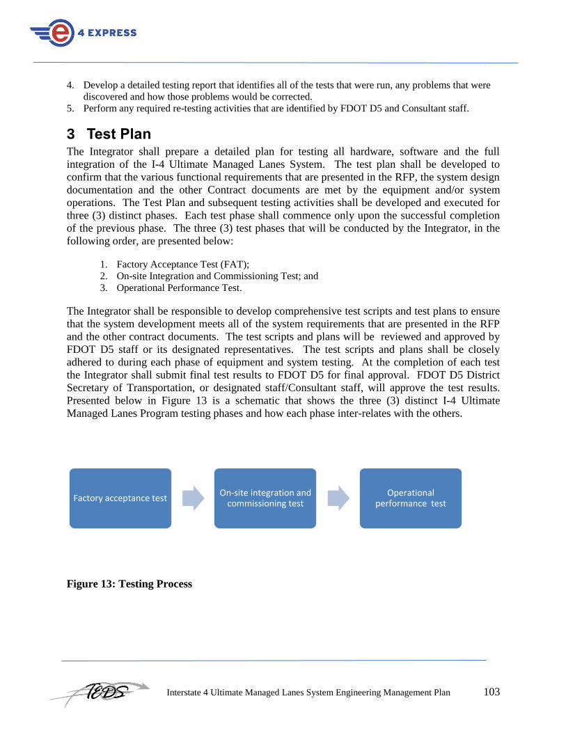
Interstate 4 Ultimate Managed Lanes System Engineering Management Plan 103
4. Develop a detailed testing report that identifies all of the tests that were run, any problems that were
discovered and how those problems would be corrected.
5. Perform any required re-testing activities that are identified by FDOT D5 and Consultant staff.
3 Test Plan The Integrator shall prepare a detailed plan for testing all hardware, software and the full
integration of the I-4 Ultimate Managed Lanes System. The test plan shall be developed to
confirm that the various functional requirements that are presented in the RFP, the system design
documentation and the other Contract documents are met by the equipment and/or system
operations. The Test Plan and subsequent testing activities shall be developed and executed for
three (3) distinct phases. Each test phase shall commence only upon the successful completion
of the previous phase. The three (3) test phases that will be conducted by the Integrator, in the
following order, are presented below:
1. Factory Acceptance Test (FAT);
2. On-site Integration and Commissioning Test; and
3. Operational Performance Test.
The Integrator shall be responsible to develop comprehensive test scripts and test plans to ensure
that the system development meets all of the system requirements that are presented in the RFP
and the other contract documents. The test scripts and plans will be reviewed and approved by
FDOT D5 staff or its designated representatives. The test scripts and plans shall be closely
adhered to during each phase of equipment and system testing. At the completion of each test
the Integrator shall submit final test results to FDOT D5 for final approval. FDOT D5 District
Secretary of Transportation, or designated staff/Consultant staff, will approve the test results.
Presented below in Figure 13 is a schematic that shows the three (3) distinct I-4 Ultimate
Managed Lanes Program testing phases and how each phase inter-relates with the others.
Figure 13: Testing Process
Factory acceptance test On-site integration and
commissioning test Operational
performance test

Interstate 4 Ultimate Managed Lanes System Engineering Management Plan 104
FDOT D5 and their representatives will be permitted to participate in or otherwise observe any
and all of these tests at FDOT D5’s sole discretion. Tentative dates for conducting the various
tests shall be included in the Test Plan document that shall be submitted by the Integrator during
the system design phase of the Contract. Reasonable modifications to these dates may be
permitted during the course of the work by FDOT D5 provided a written request for such change
is made at least two (2) weeks prior to the revised test date. The actual change approval must be
granted, in writing, by FDOT D5.
3.1 Equipment Environmental Testing
As a preliminary effort prior to factory acceptance testing, the Integrator shall also provide test
results, certified by a testing laboratory approved by FDOT D5, confirming that all proposed
system equipment that is to be installed is suitable to operate within its respective environment.
If certified test results are not available or the results are not satisfactory to FDOT D5, the
Integrator shall arrange for such tests to be conducted or re-conducted at no additional cost to
FDOT D5. The Integrator shall provide FDOT D5 with certified test results for all equipment
that is to be installed outside, or in any other non-environmentally controlled location. For
equipment that is to be installed inside a building, cut sheets showing environmental operating
requirements will be acceptable.
3.2 Factory Acceptance Test (FAT)
The intent of the FAT, which will be held at the Integrator’s system development office, is to
allow the Integrator to conclusively represent that the I-4 Ultimate Managed Lanes equipment,
subsystems and overall system complies with the system functional requirements.
Representatives from FDOT D5, the Consultant group, and FTE are expected to be present at the
FAT. The FAT shall be successfully completed, and accepted by FDOT D5, prior to
commencement of on-site equipment installation, system integration and field testing.
Equipment and/or system failures that are encountered during performance of the FAT shall be
resolved, retested and acknowledged as being resolved by FDOT D5 prior to issuance of FAT
approval to the Integrator.
It is possible that certain components that comprise the overall I-4 Ultimate Managed Lanes
System may not be available during factory testing. The Test Plan shall indicate those portions
or components that will not be able to be verified during performance of the FAT. Where
applicable, the Integrator shall attempt to simulate the missing components to represent a fully
functioning system.
Components used in the FAT shall be production models, which would otherwise be suitable for
installation in the I-4 Ultimate Managed Lanes System. Testing and careful evaluation of
samples and prototypes shall be completed prior to the commencement of the FAT.
The FAT is the culmination of the design, development, fabrication and pre-test of the Managed
Lanes System equipment, subsystems and overall system. The FAT shall be performed by the
Integrator under the supervision of, and with the participation of, FDOT D5. Performance of the

Interstate 4 Ultimate Managed Lanes System Engineering Management Plan 105
FAT shall be witnessed by FDOT D5, and their representatives, with acknowledgment of
scenario success and/or failure by FDOT D5.
The Integrator shall prepare detailed test scripts that will be used as the basis for the FAT. FAT
Scripts shall cover test set-up, step-by-step procedures and pre-determined expected results.
FAT scripts shall be submitted and approved by FDOT D5 prior to the commencement of the
FAT. FAT scripts shall be submitted for review and approval no less than 60 days prior to
scheduling of the factory test.
The following are recommended features of the Managed Lanes System that are, at a minimum,
to be demonstrated during the FAT:
• Equipment power up tests
• Verify initialization
• Verify data integrity (no loss of data)
• Verify diagnostic messages
• Introduce failures and threats
• Degraded mode performance
• Verify diagnostic messages
• Normal transaction tests
• Tolling zone operational tests
• Proper association of vehicle and transponder
• Tolling zone stand-alone tests
• Operation of the FTE Tolls Back Office modules including the dynamic pricing algorithms and
the trip generation process
• Interface to FDOT D5 Regional Traffic Management Center (RTMC)
• Communication link between the tolling zones and the FTE Tolls Back
• Generation of traffic, toll revenue and reconciliation reports
• Data analysis
• Integrity checking
• System audit and
• Others yet to be identified
3.3 On-Site Integration and Commissioning Test
The On-site Integration and Commissioning Test (OICT) shall be comprised of equipment,
subsystem and system-wide testing of the Managed Lanes System. The purpose of the OICT is
to provide both the Integrator and FDOT D5 a mechanism for verifying and documenting
successful system performance throughout the installation process up to the point of approval to
Commission the lane. Testing procedures and scenarios, which will be developed by the
Integrator and subject to FDOT D5 approval, shall be built upon the previously utilized FAT
scripts and test steps.
At the subsystem and component level(s), the OICT shall cover installation check-out and
performance verification at each applicable location throughout the I-4 Ultimate Managed Lanes

Interstate 4 Ultimate Managed Lanes System Engineering Management Plan 106
System. At the system wide level, the OICT shall also cover end-to-end testing that represents a
fully integrated and functional Managed Lanes System with all subsystems and components
successfully integrated on-site. The intent of end-to-end testing during the OICT phase is to
ensure readiness for the subsequent Commissioning Test.
The Integrator shall prepare detailed test scripts for the OICT. OICT scripts shall be designed to
verify the equipment installation and confirm that the subsystem and/or component(s) are ready
for operation on the Managed Lanes System and the Commissioning Test can then commence.
The tests to be performed shall be defined in the Integrator’s test plan and test scripts. The
detailed test scripts and scenarios of the Test Plan shall be submitted and approved by FDOT D5
prior to commencement of any of the specific tests. Performance of the various tests shall be
witnessed by FDOT D5 with acknowledgment of scenario success, failures or potential system or
equipment threats.
The commissioning portion of the OICT will be conducted in order to represent the operational
readiness of the system prior to deployment. Testing activities and scenarios during these tests
shall include complete end-to-end testing of all functions and operations of the Managed Lanes
System. This testing will involve live traffic in the Managed Lanes, both real traffic and test
vehicles. To ensure that all of the stated RFP and Contract operating requirements are
effectively met, the Integrator shall develop a comprehensive requirements trace matrix and
confirm, in writing to FDOT D5, that the tolling system has met each and every stated
requirement.
Any failures that are encountered during the Commissioning Test must be resolved, retested and
acknowledged by FDOT D5 before opening of the I-4 Ultimate Managed Lanes and
commencement of the Operational Performance Test (OPT). The tests to be performed shall be
similar to the tests in the FAT and shall be conducted under the supervision of, and with the
participation of FDOT D5, and their representatives, in accordance with the test plan and test
scripts that were previously approved. Testing results and corresponding documentation
regarding the completion of the OICT shall be submitted to FDOT D5 for approval. Approval of
the OICT must be granted prior to commencement of the Commissioning Test.
3.4 Operational Performance Test (OPT)
The final phase of testing of the I-4 Ultimate Managed Lanes System is the OPT. This test shall
serve to closely monitor the performance of the managed lanes under live traffic operating
conditions once the managed lanes are open to toll-paying vehicles. Activities during this period
of testing will include all necessary scripted test documentation, unscripted ad-hoc tests as well
as monitoring of day-to-day functions of the Managed Lanes System, including the operation of
the equipment at the three (3) tolling zones, the operation of the FTE Tolls Back Office, trip
building functionality at the FTE Tolls Back Office.
The OPT shall be conducted over a 30-day continuous period without degradation in
performance or failure in compliance with contract system requirements. Throughout the 30-day

Interstate 4 Ultimate Managed Lanes System Engineering Management Plan 107
test period any system problems, errors, failures or malfunctions that are not in compliance with
the contract requirements shall be categorized based on its level of severity. The typical four (4)
levels of severity are:
Severity 1 – Hardware or Software component or process that is critical to the operation of the
Managed Lanes that does not function and there is the possibility of loss of revenue and/or loss of
data.
Severity 2 – Hardware or software component or process that does not function. There is no risk
of loss of revenue or data; however there is the possibility of negative impact to patron usage.
Severity 3 – Hardware or software component or process that does not meet the design
functionality and/or impedes the operation of the system but does not affect the collection of
revenue or negatively impact the patron usage.
Severity 4 – Hardware or software component or process that does not meet the design
functionality and/or is “cosmetic” in nature. Failure is transparent in nature to both the patron
and FDOT D5.
The success or failure of the 30-day OPT shall be determined by the number and type of severity
levels encountered during the test. The following represents the impact of each of the severity
levels on the eventual outcome of the test.
3.4.1 Severity 1
Indicates a failure of the 30-day test.
The 30-day test is stopped. Once the problem is resolved, the 30-day test is restarted
from Day 1.
Milestone payments regarding the 30-day test are withheld.
Warranty period will not begin until successful conclusion of the OPT.
3.4.2 Severity 2
Does not indicate a failure of the 30-day test.
The 30-day test is stopped. Once the problem is resolved, the 30-day test will resume
from the date in which it left off. Once the problem is resolved the implemented fix
shall operate without flaw for seven (7) consecutive days, which may extend the 30-
day test period.
Milestone payments regarding 30-day test will be withheld.
Warranty period will not begin.
Reoccurrence of the same problem that should have been resolved might raise the
level of the issue to Severity 1.
3.4.3 Severity 3
Does not indicate a failure of the 30-day test.
The 30-day test is stopped. Once the problem is resolved, the 30-day test will resume
from the point in which it left off. Once the problem is resolved the fix shall operate
without failure for a minimum of seven (7) consecutive days, which may extend the

Interstate 4 Ultimate Managed Lanes System Engineering Management Plan 108
30-day test period.
Milestone payments will continue to be paid to the Integrator.
The Warranty Period will not begin.
3.4.4 Severity 4
Does not indicate a failure of the 30-day test.
The 30-day test is not stopped. The problem is resolved in a timely fashion.
Milestone payments will continue to be paid.
The Warranty Period will not begin.
All I-4 Ultimate Managed Lanes hardware and software will be carefully tested. Verification
that all reported problems have been resolved will be obtained using several methods, including
event logs and service call logs and other additional information that can be gleaned from the
Maintenance On-Line Management System maintained by the Integrator or other data sources
approved by FDOT D5. Multiple meetings per week will be scheduled during the 30-day test to
ensure that FDOT D5 is fully aware of all system and equipment failures and the meetings will
provide a forum in which FDOT D5 and Integrator staff can review system/equipment failures
and classify the severity levels.

Interstate 4 Ultimate Managed Lanes System Engineering Management Plan 109
Appendix K: Deployment Plan Guidelines

Interstate 4 Ultimate Managed Lanes System Engineering Management Plan 110
1 General The I-4 Ultimate Express Lanes Deployment Plan will provide the details of planned installation
of the I-4 Ultimate Express Lanes I-4 Ultimate Express Lanes roadside, FTE, Regional Traffic
Management Center, and system enforcement equipment and subsystems. This document
provides guidelines for the creation of the Deployment Plan by the Integrator.
2. Roles and Responsibilities To ensure successful I-4 Ultimate Express Lanes deployment and operations, and to make certain
that the delivered tolling, pricing and ITS operates according to the RFP and contract
requirements, the I-4 Ultimate Express Lanes project engineering organization will have various
roles and responsibilities. Guidelines for defining organizational responsibilities are listed below
in the following sections. are starting points for defining the various organizational
responsibilities.
2.1. FDOT D5 Staff
FDOT D5 shall have contractual responsibility for all of the I-4 Ultimate Express Lanes system
deployment activities, and will work closely with consultants and Integrator staff to ensure that
equipment performs correctly and that the system deployment is correct.
2.2. Project Consultant Staff
FDOT D5’s I-4 Ultimate Express Lanes consultant staff will be responsible for ensuring that the
Integrator develops and maintains system deployment engineering related processes, policies,
and operating procedures. Consultant staff shall participate in all facets of the deployment
activities at critical points in the process to verify that the deployment activities are conducted
and administered correctly. The consultant shall provide any required technical assistance to the
Integrator and FDOT D5 staff during the system deployment process.
2.3. Integrator’s Engineering Staff
The Integrator’s system engineering Staff for the I-4 Ultimate Express Lanes Project shall be
responsible for developing all documents required to support the I-4 Ultimate Express Lanes
system deployment process. Integrator staff shall perform all work associated with deploying the
I-4 Ultimate Express Lanes, including the required field testing, as described in the Verification
(Test) Plan, RFP, and the contract documents.
The Integrator shall ensure that the system deployment requirements and processes are adhered
to, including confirmation that the requirements within the trace matrix are met.
Integrator staff shall develop all required system deployment documentation, which will be
subject to review and approval by FDOT D5. Integrator staff shall also perform any required
testing and re-testing activities identified by FDOT D5 and consultant staff. Details of the
Integrator’s staff are described in Section 4 below.

Interstate 4 Ultimate Managed Lanes System Engineering Management Plan 111
3. Purpose of Deployment Plan The Deployment Plan shall include, at a minimum, a comprehensive Installation Plan that
includes a detail schedule, a Training Plan, and an Installation Safety Plan.
The equipment and software deployment techniques that will be used on the I-4 Ultimate
Express Lanes Project by the Integrator shall be clearly defined in the Installation Plan. If
accepted by FDOT D5, the Installation Plan will be applied to all equipment, subsystem, and
software installations. Step-by-step scenarios for the installation of roadside equipment,
telecommunications network, FTE Tolls Back Office equipment, enforcement equipment, and
the Regional Traffic Management Center subsystem shall be provided by the Integrator,
combined with the Installation Plan Schedule for these various activities. The Installation Plan
Schedule, which will be a sub-schedule of the Integrator Project Schedule, as described in the
Development Plan Guidelines, shall match the relevant milestone dates in the Overall Project
Schedule.
The following outline sequence of deployment activities will be performed by the Integrator.
The detailed Installation Plan Schedule, to be provided by the Integrator, will show the
individual tasks associated with the installation of equipment for each subsystem.

Interstate 4 Ultimate Managed Lanes System Engineering Management Plan 112
Pre-Installation Activities as follows:
Verify civil and conduit work
Work with FDOT D5 to finalize the Installation Plan, Installation Schedule and other
deployment documents
Ensure that all safety procedures are in place
Secure FDOT D5 Encroachment Permit
Roadside Equipment Installation as follows:
SunPass Antennas and Readers
Tolling Zone Lane Controllers
Enforcement Beacons
Vehicle Detection System (VDS) Equipment
CCTV Equipment
Communications Network Equipment
Other equipment as identified in the RFP and civil plans
FTE Tolls Back Office Equipment Installation as follows:
Trip Processor Hardware and Software
Customer Service Representative Workstations
FDOT D5 I-4 Ultimate Express Lanes Website
Interface to the SunPass Customer Service Center
Interface to FDOT D5 Regional Traffic Management Center
Interface to the Enforcement Agency Enforcement Equipment
Other equipment as identified in the RFP and civil plans
Post-Installation Activities as follows:
Verify that all the equipment and software is installed properly
Verify that each internal subsystem communicates properly to each other
Verify that all install equipment and software operates properly by conducting end-to-end
systems testing
4. System Deployment Staff
4.1. I-4 Ultimate Express Lanes Integrator
The Integrator shall be fully responsible for all I-4 Ultimate Express Lanes deployment activities
and will provide leadership in the management of the system integration, installation, testing, and
commissioning process. The Integrator shall provide the, complete I-4 Ultimate Express Lanes,
with integration of the various other subsystem components that are expect to be procured from
vendors, including the SunPass equipment, VDS equipment, CCTV equipment, workstations,
etc. It will be the responsibility of the Integrator to conduct the electrical work or to bring an
Electrical Subcontractor on board to perform this work. The chosen Electrical Subcontractor
shall be approved by FDOT D5 prior to any work that is conduct in the field.
4.2. Integrator Staff Qualifications
Only qualified Integrator staff and their subcontractor representatives shall be present on site to
perform any pre-installation or actual installation work. Integrator staff should have all required
electrical licenses and other required installation permits prior to starting any work. Only highly

Interstate 4 Ultimate Managed Lanes System Engineering Management Plan 113
skill Integrator staff, with many years of toll system implementation experience, shall oversee
the system deployment activities.
4.3. Integrator Management Support and Services
During the system deployment, and operational testing activities (as defined in the Verification
Plan), the Integrator shall provide an integrated, well organized I-4 Ultimate Express Lanes
Management Team of staff from the Integrator and any of their subcontractors, including the
SunPass equipment vendor. All system deployment Team members shall be knowledgeable and
experienced in their respective fields of expertise, and will provide a quality product within the
scheduled parameters that are established by FDOT D5. As part of the response to the RFP, the
Integrator shall provide an organization chart clearly depicting the deployment Team along with
documentation of their qualifications. The staffing shall be subject to the approval of FDOT D5.
4.4. Integrator Project Manager
The Integrator shall nominate a Project Manager (PM) subject to the approval of FDOT D5. The
Integrator’s PM shall be FDOT D5’s primary point of contact throughout the duration of the
project. During the deployment effort, the Integrator PM’s primary responsibilities shall include,
at a minimum:
Primary communications with FDOT D5 and consultants
I-4 Ultimate Express Lanes contract administration
Ensure adherence to the quality assurance and control process
Schedule and administer the I-4 Ultimate Express Lanes Project status meetings
Interface with the Integrator’s Installation Manager and all of the Integrator’s subcontractors
Coordinate with Florida regulatory agencies, FDOT D5 staff, FTE Tolls Back Office staff,
permitting agencies, vendors, etc.
The Integrator PM shall ensure that all resources are allocated to the I-4 Ultimate Express Lanes
Project and are us in the most advantageous manner. Additional Integrator Deployment Team
members are list below with their areas of expertise and their specific responsibilities.
4.5. Chief Technical Officer
The Integrator Chief Technology Officer (CTO) shall be responsible for all technical functions
on the I-4 Ultimate Express Lanes Project. During the system deployment and installation
activities, the CTO’s responsibilities, at a minimum, shall include:
Equipment specifications (hardware and software)
Contractual documentation
Testing and acceptance procures
Integration testing and debugging
90-Day System Performance Testing

Interstate 4 Ultimate Managed Lanes System Engineering Management Plan 114
4.6. Installation Manager
The Integrator’s Installation Manager shall be responsible for the proper installation of all on site
equipment, local installation support requirements and purchases. The Installation Manager will
remain on site during the entire system installation phase of the I-4 Ultimate Express Lanes
Project, including the post-commissioning testing phase. The Installation Manager will be
responsible for confirming that all subcontractor work is completed properly and meets the
System Requirements. The Installation Manager shall recommend acceptance of the system by
FDOT D5.
The Installation Manager’s responsibilities would include, at a minimum:
Site survey;
Verify civil work;
Supervise cable and fiber optic installation, splicing and testing;
Supervise equipment installation and start-up;
Warehouse and inventory control;
Maintain field records and installation logging; and
Develop and maintain safety records.
4.7. Hardware Installation Engineer
The Integrator’s Hardware Installation Engineer shall be responsible for the hands-on installation
of all roadside equipment and all hardware installation at the FTE Tolls Back Office, on the
Enforcement Agency vehicles, and at the FDOT D5 Regional Traffic Management Center. The
Hardware Installation Engineer shall be on-site as necessary during the installation phase of the
I-4 Ultimate Express Lanes Project and shall have, at a minimum, the following responsibilities:
Supervision of other Integrator hardware installation staff
Installation of the roadside equipment
Supervision of any subcontractors that might provide SunPass, CCTV, Vehicle Detection
System (VDS) and enforcement equipment
Supervision of the Electrical Subcontractor, if the Integrator chooses to use the services of a
subcontractor, on roadside equipment power wiring terminations
Terminations of roadside, enforcement and FTE Tolls Back Office equipment control wiring
Lane equipment start-up and verification testing
4.8. FTE Tolls Back Office Installation Engineer (Hardware and Software)
The Integrator’s FTE Tolls Back Office Installation Engineer shall be responsible for the
required hands-on installation of FTE Tolls Back Office hardware and software, including the
interfaces to FDOT D5 Regional Traffic Management Center, the SunPass Customer Service
Center, and the Enforcement Agency vehicles in support of the enforcement process. The FTE
Tolls Back Office Installation Engineer shall be on-site after the communications network has
been successfully install and test. The FTE Tolls Back Office Installation Engineer shall have, at
a minimum, the following responsibilities:

Interstate 4 Ultimate Managed Lanes System Engineering Management Plan 115
Supervise other FTE Tolls Back Office related Integrator hardware and software staff
Install all required switches and hubs to the FTE Tolls Back Office patch panels
Test the FTE Tolls Back Office local area network (LAN) to ensure its proper operation
Install all the FTE Tolls Back Office servers and software
Configure FTE Tolls Back Office servers operating system
Configure and install the various FTE Tolls Back Office workstations and peripheral
hardware
Install the application software on the FTE Tolls Back Office servers and workstations
Test roadside, FTE Toll Back Office, FDOT D5 and Enforcement Agency enforcement
equipment connectivity and data transfer process
4.9. Roadside Equipment Software Support Engineer
The Integrator shall also appoint a Roadside Equipment Software Support Engineer to the I-4
Ultimate Express Lanes Project who will be responsible for overseeing the Integrator’s roadside
equipment and subsystem testing activities. The Engineer shall be on-site as necessary
subsequent to the successful installation and pre-testing of the roadside equipment by the
Integrator’s Hardware Installation Engineer. The Roadside Equipment Software Support
Engineer shall have, at a minimum, the following responsibilities:
Oversee the fine tuning of the SunPass equipment once the antennas have been successfully
tuned by the vendor
Oversee the Integrator testing activities of the roadside I-4 Ultimate Express Lanes equipment
to include both the low speed and high speed testing (of up to 100 mph)
Ensure that the SunPass lanes provide the correct data and other system information to the
lane controllers and on to the FTE Tolls Back Office, in close cooperation with the FTE Tolls
Back Office Installation Engineer
4.10. Subcontractors
All I-4 Ultimate Express Lanes work to be performed by a subcontractor(s) shall be clearly
defined in the Integrator’s Technical Proposal, and in the system deployment and installation
documentation that they shall be required to develop. FDOT D5 shall have the right to accept or
reject any subcontractor
4.11. Installation Equipment and Tools
During the system installation process, the Integrator installation crews will have at their disposal
all the necessary drills, cutters, and hardware tools to support the installation effort. The
Integrator shall provide a detail list of all required equipment and tools needed to support the
deployment effort. Below is a typical list of the types of equipment and tools required to
properly install electronic toll collection systems elements.
All required safety equipment necessary for a safe system installation, including (but not
limited to) steel-toe boots, safety cones, hard hats, eye protection, fall protection to 6 feet,

Interstate 4 Ultimate Managed Lanes System Engineering Management Plan 116
safety vests, first aid kits, etc.
All necessary layout, electrical and mechanical drawings
Platform truck for canopy installation and a palette jack and/or truck lift gate to unload heavy
equipment
Fiber optic polishing and termination tool kit, mesh slings to grasp cable ends that must be
pull from conduits, conduit mandrill to clean out block conduits, cable markers, a bonding
product to secure loop and wires in a VDS loop cut, inductive loop cutting machine, loop
sealant
An assortment of tools, including hammers, measuring tapes, hacksaws, pliers, screwdrivers,
step ladders in varying sizes, tools for terminating various types of cables, etc.
During the initial 90-Day Operational Performance Test, a complete software development
system shall be made available by the Integrator for quick on-site debugging capabilities.
5. Electronic Toll System Documentation A complete and updated set of I-4 Ultimate Express Lanes related documentation shall be kept
by the Integrator at their I-4 Ultimate Express Lanes Project office, which should be located near
the three tolling zone locations and the FTE Tolls Back Office site. Integrator technicians shall
retain their own set of documentation in accordance with their specific needs in a secure manner,
which will periodically be check by the appropriate Integrator manager to ensure its revision
validity. All documentation shall be conveyed to FDOT D5 both in hard copy and electronically.
FDOT D5 shall retain an updated version documentation file for project consistency.
6. Installation Considerations
6.1. Installation Safety
Job safety is of paramount importance. All Integrator staff, before being allowed to provide
direct installation support, shall comply with all safety and drug screening requirements establish
by FDOT D5. Integrator staff working on the installation phase of the I-4 Ultimate Express
Lanes Project shall also participate in a FDOT D5 approved safety orientation session, which
will include information about FDOT D5 encroachment permit requirements. The Integrator
installation staff is also required by FDOT D5 to use the following staff safety equipment:
Hard hats
Eye protection
Steel-toe boots
Reflective safety vests
Fall Protection (up to 6 feet)
All Integrator and subcontractor installation staff shall be provided with a copy of FDOT D5
safety requirements to ensure that they are familiar with the various on-site job safety
requirements. The Integrator shall also provide weekly safety briefings that involve all

Interstate 4 Ultimate Managed Lanes System Engineering Management Plan 117
Integrator and subcontract staff to confirm that they are adhering to FDOT D5 safety
requirements. The Integrator shall be required to develop, submit for FDOT D5 approval, and
periodically update a General Safety Plan. This Plan shall be adhered to in order to ensure the
safety of all staff, motorists and pedestrians.
6.2. Code and Industry Standards
All applicable codes and standards shall be adhered to by the Integrator. FDOT D5 will
periodically check to confirm that all required standards are being met by the Integrator.
6.3. Installation Planning
As described previously in this document, a detail Installation Schedule shall be developed by
the Integrator, submitted to FDOT D5 for approval and periodically updated. Any changes are
subject to approval by FDOT D5. The Installation Schedule shall be updated on a weekly basis,
showing progress of tasks in a percentage completed format. The Installation Schedule will be
formatted to provide a separate two-week look ahead feature to be used during the
Integrator/FDOT D5 weekly progress and planning meetings. The Integrator will be expect to
coordinate work with other I-4 Ultimate Express Lanes contractors to ensure that simultaneous
work efforts can be accomplish as quickly as possible.
6.4. Weather And Productivity
The Integrator should make every effort to plan for weather delays and productivity concerns
during bad weather conditions. For example, some of the work at the FTE Tolls Back Office
could be saved as a fall back for when bad weather appears. The emphasis during good weather
should be focus on outside work, including gantry or canopy equipment and conduit installation.
6.5. Shop Drawing Submittals
The Integrator shall be required to develop and submit shop drawings prior to the installation, to
enable sufficient time for FDOT D5 review and approval process. The drawings shall be
updated and revised to reflect the actual installation conditions. The updated shop drawings
would be resubmitted by the Integrator as final As Built drawings.
6.6. Installation Daily Cleanup
The Integrator and their Subcontractors shall thoroughly clean up their work area on a daily basis
and leave the installation site in an orderly manner.
Installation Records
A detail installation log of the Integrator’s work effort at each location shall be develop, maintain
carefully, and submitted as part of the weekly review meetings with FDOT D5.
Interstate 4 Ultimate Managed Lanes System Engineering Management Plan 118
7. System Testing and Acceptance When the I-4 Ultimate Express Lanes system has been subject to complete verification testing
and commissioning as defined in the Verification Plan, the Operational 90-Day Test period shall
commence to provide proof that the system is operating at a level that warrants acceptance by
FDOT D5. During the Operational Performance Test period, the Integrator shall provide system
support and maintenance. Refer to the Verification (test) Plan for additional details.
During this testing period, Integrator staff shall be available on-site to perform all their required
duties. Integrator staff shall perform all preventive, corrective, and emergency maintenance, as
necessary, to ensure the proper performance and operation of the I-4 Ultimate Express Lanes
system. Equipment, subsystem, and overall system reliability is the primary concern during this
period. The Integrator shall adhere to all FDOT D5 mandated maintenance and testing
procedures. This will assist the Integrator to achieve required levels of performance, reliability,
maintainability, system availability and performance. The objectives is for the Integrator to
provide FDOT D5 with sufficient evidence that the installed I-4 Ultimate Express Lanes system
meets the reliability and operating requirements specified in the RFP and other contract
documents. During the test, the maintainability requirements shall also be demonstrated by the
Integrator.
7.1. Operational Performance Test Records
Integrator staff will keep operational and maintenance records during the test period. All
problems, failures, malfunctions, service calls, and any performance issues relating to equipment,
software, subsystems, or the overall system shall be documented and submitted for review by
FDOT D5 on a weekly basis, at a minimum.
7.2. Corrective Action
Problems encountered during the 90-Day Test that might indicate that a system component or
module does not meet the operational, reliability, maintainability or accuracy requirements, will
be analyzed and resolved by implementing an appropriate revision. FDOT D5 shall be informed
of the issue. On resolution of the issue, FDOT D5 will be provided with details of the revision
and/or solution that was implemented.
7.3. Observation And Operational Performance Test Records
A copy of service reports shall be submitted by the Integrator to FDOT D5 on a monthly basis, at
a minimum. FDOT D5 staff will have access to service records at all times. A hardware and
software Maintenance Log shall be kept by Integrator staff. All preventive, corrective,
emergency maintenance, software changes, and/or upgrades performed on any equipment during
the Test period will be carefully noted in the Maintenance Log.

Interstate 4 Ultimate Managed Lanes System Engineering Management Plan 119
The Maintenance Log will contain a description of the fault, the effort required to repair it, the
serial numbers and description of the equipment, date and time of the start and finish of the
work, technician's name(s), problem notification time, tolling zone location, and signature boxes
for both FDOT D5 and Integrator staff to sign. This data will provide records of system
operation to assist FDOT D5 and the Integrator in establishing accurate preventive maintenance
schedules, required inventory levels, maintenance staff requirements, and an indication of
recurring problems with particular system components. This data will be valuable as the
Integrator tracks equipment, subsystem and total system operation during the 12-month Warranty
Period.
7.4. Installation Schedule
As described previously, the Integrator shall develop and submit, for FDOT D5 review and
approval, a detail I-4 Ultimate Express Lanes Installation Schedule. The Installation Schedule
shall include concise description of the equipment, subsystem, etc., that the Integrator proposes
to install and the proposed installation location. The expected time for each system component,
subsystem, etc. to be installed, tested and deployed, shall also be documented in this schedule.
Integrator and FDOT D5 staff shall comply with the dates stated in the Installation Schedule to
ensure the I-4 Ultimate Express Lanes system deployment process stays on scheduled.
8. Integrator Training The training of FDOT D5 staff shall be provided prior to hands-on operation of the I-4 Ultimate
Express Lanes system. The training process overview is as follows:
8.1. FTE Tolls Back Office Supervisor staff:
1. FTE Tolls Back Office system operator overview
2. FTE Tolls Back Office workstation overview
3. Interface to the FTE Toll Back Office SunPass account management system
4. Interface to FDOT D5 Regional Traffic Management Center
5. Interface to the Enforcement Agency enforcement system
6. Navigation of FDOT D5 website
7. Access to the Maintenance On-Line Management System (MOMS)
8. Access to Integrator maintenance staff
9. Access to I-4 Ultimate Express Lanes Operations staff (if FDOT D5 chooses to use the
Integrator or a second source company)
8.2. FTE Tolls Back Office Customer Service Representative staff:
10. FTE Tolls Back Office system Customer Service Representative overview
11. FTE Tolls Back Office workstation overview
12. Interface to the FTE Toll Back Office SunPass account management system
13. Interface to FTE Toll Back Office Customer Service Representatives
14. Navigation of FDOT D5 Website

Interstate 4 Ultimate Managed Lanes System Engineering Management Plan 120
9. Conclusions The Integrator will develop System Deployment Plan Guidelines that clearly describe the
management approach that will be implemented to ensure that the I-4 Ultimate Express Lanes I-4
Ultimate Express Lanes deployment activities are performed correctly. The Integrator’s
Deployment Plan shall include all required information regarding the approach to managing the
equipment, software, system installation, deployment process and planned testing procedures
that will be used.

Interstate 4 Ultimate Managed Lanes System Engineering Management Plan 121
Appendix L: Electronic Tolling and Pricing Requirements

Interstate 4 Ultimate Managed Lanes System Engineering Management Plan 122
Sub System Name Sub System Number
Requirement Number
Functional Requirement Label
Functional Requirement Description
Dynamic tolling System 1100 1 Traffic Pricing Calculation
The FDOT D5 dynamic tolling system shall periodically and dynamically calculate the toll rate based upon traffic information from both the Managed Lanes and the General Use lanes gathered from the vehicle detection system and traffic sensor devices installed along the facility
Dynamic tolling System 1100 2 Traffic Pricing Calculation
The toll rate setting process shall accommodate the objective to minimize congestion and maximize gross toll revenue obtained subject to a maximum toll, minimum level of service and support dynamic re-pricing intervals of no less than 5 minutes
Dynamic tolling System 1100 3 Traffic Pricing Calculation
The Contractor shall maintain sufficient design flexibility to permit incorporation of objectives such as maintenance of minimum LoS or other policy objectives in the future
Dynamic tolling System 1100 4 Traffic Pricing Calculation
dynamic, real-time, parameter- or heuristic-driven toll rate calculation program that successfully achieves the stated toll and operational objectives and constraints

Interstate 4 Ultimate Managed Lanes System Engineering Management Plan 123
Sub System Name Sub System Number
Requirement Number
Functional Requirement Label
Functional Requirement Description
Dynamic tolling System 1100 5 Traffic Pricing Calculation
toll rate calculation process that accounts for traffic flow densities in both the Managed Lanes and vehicle travel times in the General Use lanes
Dynamic tolling System 1100 6 Traffic Pricing Calculation
toll rate calculation program that accounts for disparities in traffic densities occurring simultaneously at various locations over the entire length of the I-4 Ultimate Managed Lanes corridor
Dynamic tolling System 1100 7 Traffic Pricing Calculation
toll-rate reset interval (e.g., every 5 minutes) that successfully controls Managed Lanes demand without creating driver confusion by changing too frequently, or sacrifices facility objectives by not changing frequently enough
Tolling Zone Lane Controller 200 8 Traffic Pricing Calculation
individual operator adjustable toll rate increment in dollars and cents that successfully manages Managed Lanes demand to system criteria
Dynamic tolling System 1100 9 Traffic Pricing Calculation
user settable minimum toll rate in dollars and cents

Interstate 4 Ultimate Managed Lanes System Engineering Management Plan 124
Sub System Name Sub System Number
Requirement Number
Functional Requirement Label
Functional Requirement Description
Dynamic tolling System 1100 10 Traffic Pricing Calculation
dynamic pricing structure that provides the ability to toll by segment.
Dynamic tolling System 1100 11 Traffic Pricing Calculation
The toll rate setting process shall assess a per-mile toll rate for each of the three segments that reflect the balancing of the value of traveling in the Managed Lanes as opposed to traveling in the General Use Lanes
Dynamic tolling System 1100 12 Traffic Pricing Calculation
A dynamic, real-time, parameter-driven toll rate setting process that successfully meters Managed Lanes traffic demand and ensures that the acceptable Managed Lanes LOS and other operational constraints are maintained. The toll rate setting process may consist of mathematical functions, algorithms, statistical procedures, and hardware and software implementations of such
Dynamic tolling System 1100 13 Traffic Pricing Calculation
A toll rate setting process that accounts for traffic densities in the Managed Lanes and vehicle travel times in the General Use Lanes

Interstate 4 Ultimate Managed Lanes System Engineering Management Plan 125
Sub System Name Sub System Number
Requirement Number
Functional Requirement Label
Functional Requirement Description
Dynamic tolling System 1100 14 Traffic Pricing Calculation
A toll rate setting process that accounts for disparities in traffic densities occurring simultaneously throughout the entire length of the Managed Lanes corridor
Dynamic tolling System 1100 15 Traffic Pricing Calculation
An interval of change for the toll rate (i.e. possibly every 5 minutes) that successfully controls Managed Lanes demand without creating driver confusion by changing too frequently
Dynamic tolling System 1100 16 Traffic Pricing Calculation
An individual operator adjustable toll rate increment that successfully controls Managed Lanes demand. Toll increment to be user programmable
Dynamic tolling System 1100 17 Traffic Pricing Calculation
A user settable minimum toll rate
Dynamic tolling System 1100 18 Traffic Pricing Calculation
A user settable maximum toll rate
Dynamic tolling System 1100 19 Traffic Pricing Calculation
A dynamic pricing structure that provides the ability to toll by segment

Interstate 4 Ultimate Managed Lanes System Engineering Management Plan 126
Sub System Name Sub System Number
Requirement Number
Functional Requirement Label
Functional Requirement Description
Dynamic tolling System 1100 20 Traffic Pricing Calculation
Ability to support the following operating modes: incident management mode, evacuation mode, total system failure mode. For instant management mode the system will have the ability to display zero tolls during the course of the incident. For evacuation mode the system shall have the ability to display zero tolls for a predefined period. For system failure mode the system shall have the ability to charge a toll based on historical data for the time of day day of week and year of operation
Dynamic tolling System 1100 21 Traffic Pricing Calculation
Methods for automatic, manual or semi-manual refinement of the process and sub-processes
Dynamic tolling System 1100 22 Traffic Pricing Calculation
Methods for seeding and training of any dynamic toll optimization routines employed
Dynamic tolling System 1100 23 Traffic Pricing Calculation
An internally consistent, and theoretically justified, method for accommodating the inherently variable value(s) of time of patrons so as to meet revenue objectives.

Interstate 4 Ultimate Managed Lanes System Engineering Management Plan 127
Sub System Name Sub System Number
Requirement Number
Functional Requirement Label
Functional Requirement Description
Dynamic tolling System 1100 24 Traffic Pricing Calculation
The process shall have a means of reporting the implied value of time of the patrons for each 24-hour period
Dynamic tolling System 1100 25 Traffic Pricing Calculation
The period at which the FDOT D5 dynamic tolling system calculates the toll rate shall be a user-settable, table-driven parameter in the ETC System
Dynamic tolling System 1100 26 Traffic Pricing Calculation
The specific calculation interval shall be initially set during the ETC System design phase of the project, but the system shall provide the ability for the FDOT D5 Secretary of Transportation, or his/her designee, to modify the parameter at any time in the future
Dynamic tolling System 1100 27 Traffic Pricing Calculation
The setting of the calculation shall be possible by non-technical persons, and designed so as to alert management and supervisors to extreme overrides

Interstate 4 Ultimate Managed Lanes System Engineering Management Plan 128
Sub System Name Sub System Number
Requirement Number
Functional Requirement Label
Functional Requirement Description
Dynamic tolling System 1100 28 Traffic Pricing Calculation
The toll rate setting process will be able to make use of at least the following real-time and archived historical performance information - cross-sectional vehicle volumes and speeds up-stream of pricing location and at each pricing location, real-time and archived toll revenue and paying vehicle volumes at each pricing location and any other information deemed absolutely necessary by the Client to achieve the toll-optimization and management objectives
Dynamic tolling System 1100 29 Traffic Pricing Calculation
The traffic data shall be collected from the Managed Lanes via traffic sensors that will be installed in the Managed Lanes approximately every half mile
Dynamic tolling System 1100 30 Traffic Pricing Calculation
To capture traffic performance in the General Use Lanes, traffic sensing devices shall be installed on the outside roadway approximately every mile along the I-4 ultimate Managed Lanes corridor. Traffic sensing equipment shall be used to collect travel time data from the General Use Lanes and shall also be used as back-up for the I-4 Ultimate Managed Lanes traffic flow density and speed
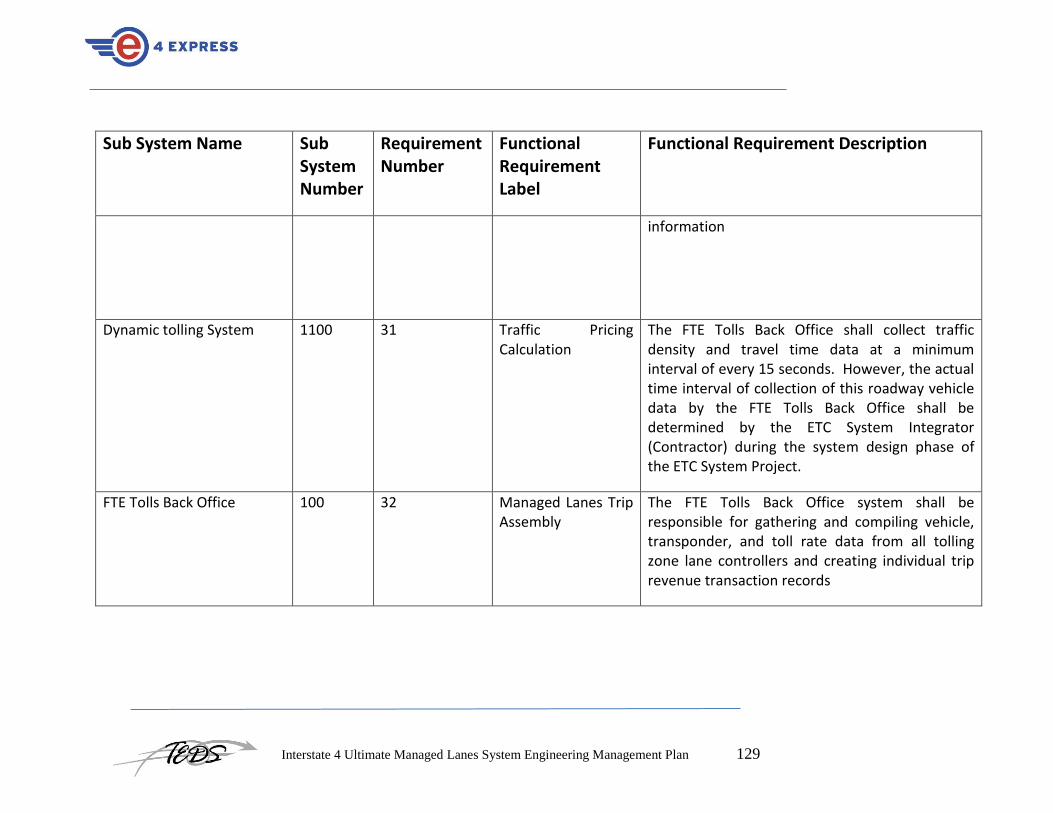
Interstate 4 Ultimate Managed Lanes System Engineering Management Plan 129
Sub System Name Sub System Number
Requirement Number
Functional Requirement Label
Functional Requirement Description
information
Dynamic tolling System 1100 31 Traffic Pricing Calculation
The FTE Tolls Back Office shall collect traffic density and travel time data at a minimum interval of every 15 seconds. However, the actual time interval of collection of this roadway vehicle data by the FTE Tolls Back Office shall be determined by the ETC System Integrator (Contractor) during the system design phase of the ETC System Project.
FTE Tolls Back Office 100 32 Managed Lanes Trip Assembly
The FTE Tolls Back Office system shall be responsible for gathering and compiling vehicle, transponder, and toll rate data from all tolling zone lane controllers and creating individual trip revenue transaction records

Interstate 4 Ultimate Managed Lanes System Engineering Management Plan 130
Sub System Name Sub System Number
Requirement Number
Functional Requirement Label
Functional Requirement Description
FTE Tolls Back Office 100 33 Managed Lanes Trip Assembly
When a SunPass™ transponder enters the Managed Lanes and passes through a tolling zone, the transponder is detected by the antenna/reader and the lane controller verifies that the transponder is valid by comparing the transponder number to the tag status file that is resident in the lane controller’s memory. Data, including the transponder number, date, time, tolling zone location of the transponder read, and the toll rate that was in effect when that vehicle entered the Managed Lanes shall be sent to the FTE Tolls Back Office system. This series of events occurs every time a vehicle that is equipped with a SunPass™ transponder passes through a Managed Lanes tolling zone. Therefore, if it is a through-trip, each time the vehicle traverses a tolling zone a distinct transaction record shall be generated

Interstate 4 Ultimate Managed Lanes System Engineering Management Plan 131
Sub System Name Sub System Number
Requirement Number
Functional Requirement Label
Functional Requirement Description
FTE Tolls Back Office 100 34 Managed Lanes Trip Assembly
If a transponder is detected but it is determined to be invalid, the lane controller shall send a command to illuminate the tolling zone beacon. The beacon shall illuminate within 0.1 seconds from the time in which the lane controller makes this determination. For each invalid transponder read a transaction record shall be developed by the lane controller and sent to the FTE Tolls Back Office system for future use
FTE Tolls Back Office 100 35 Managed Lanes Trip Assembly
The FTE Tolls Back Office system computer shall then compile each of the vehicle transaction records and event data collected throughout the specific vehicle trip and determine where the trip began, which segments were traveled, when the trip ended, and which toll should be charged
FTE Tolls Back Office 100 36 Managed Lanes Trip Assembly
The FTE Tolls Back Office system shall then determine whether or not there is a more recent Managed Lanes tolling zone transaction than the most recently received record by comparing the record times to indicate that the specific trip is now complete

Interstate 4 Ultimate Managed Lanes System Engineering Management Plan 132
Sub System Name Sub System Number
Requirement Number
Functional Requirement Label
Functional Requirement Description
FTE Tolls Back Office 100 37 Managed Lanes Trip Assembly
Based upon internal calculations, the FTE Tolls Back Office system shall develop a I4 Ultimate Managed Lanes trip record, store this record in the proper location, post to the SunPass™ customer account and collect the revenue associated with that I4 Ultimate Managed Lanes trip. The FTE Tolls Back Office system shall be designed to store I4 Ultimate Managed Lanes trip records for at least 12 months
FTE Tolls Back Office 100 38 Managed Lanes Trip Assembly
The I-4 Managed Lanes System shall include parameters that define the maximum duration for a single trip and logic that accounts for events such as a change in direction of travel or a communications failure with one or more tolling zone lane controllers
FTE Tolls Back Office 100 39 Managed Lanes Trip Assembly
The I4 Ultimate Managed Lanes system shall be configured to charge one toll per trip, for example the toll rate that is displayed on the DMS as the vehicle enters the I4 Ultimate Managed Lanes, but the I-4 Managed Lanes System shall also include functionality that allows for segment-

Interstate 4 Ultimate Managed Lanes System Engineering Management Plan 133
Sub System Name Sub System Number
Requirement Number
Functional Requirement Label
Functional Requirement Description
based tolling
FTE Tolls Back Office 100 40 Toll Rate Safeguards When a vehicle enters the I4 Ultimate Managed Lanes, the toll rate might change between the time at which the driver views the toll rate on the DMS and the time at which the driver passes through the tolling zone. Based upon near real-time traffic density and speed data, the FTE Tolls Back Office system shall calculate the amount of time it takes for a vehicle to view the toll rate and then pass through the tolling zone that is immediately downstream from the DMS that conveyed the toll rate to that vehicle operator. If the toll rate changes during that interval of time, the driver shall be charged the lesser of the two rates
FTE Tolls Back Office 100 41 Toll Rate Safeguards The FTE Tolls Back Office system shall also include logic that accounts for DMS communication failures that result in the display of incorrect toll

Interstate 4 Ultimate Managed Lanes System Engineering Management Plan 134
Sub System Name Sub System Number
Requirement Number
Functional Requirement Label
Functional Requirement Description
rates
FTE Tolls Back Office 100 42 Trip Reconciliation The FTE Tolls Back Office system shall include I4 Ultimate Managed Lanes trip audit and reconciliation functionality. It shall provide a secure user interface which will allow FTE Tolls Back Office system staff to view and reconcile I4 Ultimate Managed Lanes trips and revenue data. The interface shall also include reporting capabilities that allow users to create, execute, and store reports
FTE Tolls Back Office 100 43 Trip Reconciliation The interface shall provide detailed transaction data such as tag-read times and locations, toll rate data, and other supporting raw transaction information. This information shall then be used to verify that trips were properly created and can be reconciled

Interstate 4 Ultimate Managed Lanes System Engineering Management Plan 135
Sub System Name Sub System Number
Requirement Number
Functional Requirement Label
Functional Requirement Description
FTE Tolls Back Office 100 44 Trip Reconciliation The interface shall allow authorized users to make adjustments to the data and correct errors in compiled revenue bearing trips. Users shall be able to adjust individual transactions or bulk transactions if it is determined that a I4 Ultimate Managed Lanes trip needs to be developed and/or modified
FTE Tolls Back Office 100 45 Trip Reconciliation The FTE Tolls Back Office system database shall store configurable audit parameters, and provide a permanent audit record, or trail, of any adjustments that are made to summary or detail information
FTE Tolls Back Office 100 46 Tolling Zone Operation Monitoring
The FTE Tolls Back Office system shall include a secure, web-based monitoring interface that shall allow authorized users to view raw and summarized transaction and event data, as it occurs in real-time, at each tolling zone
Tolling zone lane controller 200 47 Tolling Zone Operation Monitoring
The tolling zone lane controllers shall broadcast data in near real-time to the FTE Tolls Back Office system and this data shall be compiled and displayed in an easily understood, graphical

Interstate 4 Ultimate Managed Lanes System Engineering Management Plan 136
Sub System Name Sub System Number
Requirement Number
Functional Requirement Label
Functional Requirement Description
manner
FTE Tolls Back Office 100 48 Tolling Zone Operation Monitoring
The interface shall support FDOT D5 defined user roles, which includes providing different data to different user categories. The interface is intended for use by customer service representatives, operations staff and maintenance personnel
FTE Tolls Back Office 100 49 Tolling Zone Operation Monitoring
The interface shall protect customer information and operate under the requirements of State of Florida privacy legislation
FTE Tolls Back Office 100 50 FTE Tolls Back Office System Reporting
The FTE Tolls Back Office system shall provide a fully integrated reporting module to support trip generation and reconciliation, I4 Ultimate Managed Lanes operations and FDOT D5 managerial system monitoring requirements
FTE Tolls Back Office 100 51 FTE Tolls Back Office System Reporting
The module shall include predefined traffic, revenue and CSR audit reports as well as support for ad hoc reporting needs

Interstate 4 Ultimate Managed Lanes System Engineering Management Plan 137
Sub System Name Sub System Number
Requirement Number
Functional Requirement Label
Functional Requirement Description
FTE Tolls Back Office 100 52 FTE Tolls Back Office System Reporting
The reporting system shall allow users to browse, choose, and run reports through a clearly displayed and user-friendly Graphical User Interface (GUI).
FTE Tolls Back Office 100 53 FTE Tolls Back Office System Reporting
The reporting interface shall allow users to schedule reports to be run in the future
FTE Tolls Back Office 100 54 FTE Tolls Back Office System Reporting
The reporting interface shall allow reports to be output, saved, or printed in at least the following formats: On-screen; PDF; HTML and Excel.
FTE Tolls Back Office 100 55 FTE Tolls Back Office System Reporting
When accessing or running reports, the execute-to-display or execute-to-print time shall be less than one minute for each request
FTE Tolls Back Office 100 56 FTE Tolls Back Office System Reporting
The FTE Tolls Back Office system report server shall be operational and available 24 hours per day, seven days a week
Tolling Communications Network
1000 57 Data Transmission Data transmissions originating from the FTE Tolls Back Office system shall occur automatically and utilize guaranteed delivery protocol

Interstate 4 Ultimate Managed Lanes System Engineering Management Plan 138
Sub System Name Sub System Number
Requirement Number
Functional Requirement Label
Functional Requirement Description
Tolling Communications Network
1000 58 Data Transmission Data communication between the FTE Tolls Back Office system and the I4 Ultimate Managed Lanes website shall be via an Ethernet connection
FTE Tolls Back Office 100 59 FTE Tolls Back Office System Security
The FTE Tolls Back Office system shall securely maintain I4 Ultimate Managed Lanes data through a standard login and password-based security system
FTE Tolls Back Office 100 60 FTE Tolls Back Office System Security
Secure user accounts shall be administered through a system administration interface
FTE Tolls Back Office 100 61 FTE Tolls Back Office System Security
The system shall operate under the provisions of State of Florida privacy laws. For example, customer data that is output for uses other than internal I4 Ultimate Managed Lanes operations shall be masked to maintain customer privacy
FTE Tolls Back Office 100 62 FTE Tolls Back Office System Security
The database shall use security service enterprise authentication for connections to the database. This will centralize database security in one location

Interstate 4 Ultimate Managed Lanes System Engineering Management Plan 139
Sub System Name Sub System Number
Requirement Number
Functional Requirement Label
Functional Requirement Description
FTE Tolls Back Office 100 63 FTE Tolls Back Office System Security
All users shall have their own user name and password that is the same across all databases
FTE Tolls Back Office 100 64 FTE Tolls Back Office System Security
Users shall have individual resource usage limits set for them to prevent unauthorized or excessive utilization of system resources
FTE Tolls Back Office 100 65 FTE Tolls Back Office System Security
Profiles shall be used to define resource usage limits by work activity or job type
FTE Tolls Back Office 100 66 FTE Tolls Back Office System Security
Users shall be granted profiles according to their job needs
FTE Tolls Back Office 100 67 FTE Tolls Back Office System Security
The database shall be able to restrict data access down to the row level
FTE Tolls Back Office 100 68 Mobile Enforcement Equipment Data Transmission
The FTE Tolls Back Office system shall send tag status data to wireless on-board mobile enforcement equipment terminals to enable the enforcement agency officers to enforce the I4 Ultimate Managed Lanes

Interstate 4 Ultimate Managed Lanes System Engineering Management Plan 140
Sub System Name Sub System Number
Requirement Number
Functional Requirement Label
Functional Requirement Description
Tolling Communications Network
1000 69 Mobile Enforcement Equipment Data Transmission
The secure data communications application shall be hosted on a wireless network to enable enforcement vehicles to obtain the tag status file data in a real-time basis
Tolling Communications Network
1000 70 System to System Interfaces
The FTE Tolls Back Office system shall provide the FDOT D5 RTMC with traffic density and speed data from the I4 Ultimate Managed Lanes and travel time data from the General Use lanes
FTE Tolls Back Office 100 71 System to System Interfaces
The incident detection process shall be the responsibility of FDOT D5. In the event that an incident does occur that would require temporary suspension of the I-4 Managed Lanes System and/or I4 Ultimate Managed Lanes closure, this shall be accomplished via a command issued by the RTMC Manager to the FTE Back office system
Tolling Communications Network
1000 72 System to System Interfaces
As part of the I4 Ultimate Managed Lanes enforcement effort, the FTE Tolls Back Office system shall also interface to the enforcement equipment that is provided to enforcement agency
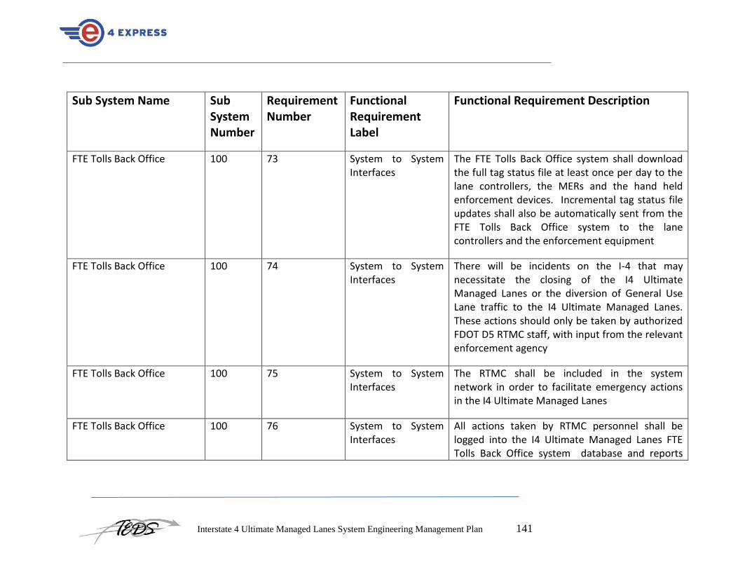
Interstate 4 Ultimate Managed Lanes System Engineering Management Plan 141
Sub System Name Sub System Number
Requirement Number
Functional Requirement Label
Functional Requirement Description
FTE Tolls Back Office 100 73 System to System Interfaces
The FTE Tolls Back Office system shall download the full tag status file at least once per day to the lane controllers, the MERs and the hand held enforcement devices. Incremental tag status file updates shall also be automatically sent from the FTE Tolls Back Office system to the lane controllers and the enforcement equipment
FTE Tolls Back Office 100 74 System to System Interfaces
There will be incidents on the I-4 that may necessitate the closing of the I4 Ultimate Managed Lanes or the diversion of General Use Lane traffic to the I4 Ultimate Managed Lanes. These actions should only be taken by authorized FDOT D5 RTMC staff, with input from the relevant enforcement agency
FTE Tolls Back Office 100 75 System to System Interfaces
The RTMC shall be included in the system network in order to facilitate emergency actions in the I4 Ultimate Managed Lanes
FTE Tolls Back Office 100 76 System to System Interfaces
All actions taken by RTMC personnel shall be logged into the I4 Ultimate Managed Lanes FTE Tolls Back Office system database and reports

Interstate 4 Ultimate Managed Lanes System Engineering Management Plan 142
Sub System Name Sub System Number
Requirement Number
Functional Requirement Label
Functional Requirement Description
generated that detail those actions
FTE Tolls Back Office 100 77 System to System Interfaces
The FTE Back office shall support an interface with the FDOT D5 Dynamic tolling System. This shall support the transmission of appropriate toll rates from FDOT D5 to FTE and a verification message to confirm that the toll has been displayed and charged
Tolling Communications Network
1000 78 Equipment Interfaces
The FTE Tolls Back Office system shall interface to each tolling zone lane controller via a real-time Ethernet connection
Tolling Communications Network
1000 79 Equipment Interfaces
The interface will support the transmission of raw vehicle, transponder, and event data. It will also support the transmission of daily incremental transponder status files and periodic toll rate data
Tolling Communications Network
1000 80 Equipment Interfaces
The interface shall be automatic and not require human intervention
Tolling Communications 1000 81 Equipment The interface control document will be developed by the Contractor during the system design phase
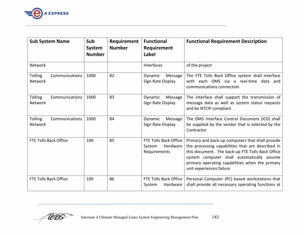
Interstate 4 Ultimate Managed Lanes System Engineering Management Plan 143
Sub System Name Sub System Number
Requirement Number
Functional Requirement Label
Functional Requirement Description
Network Interfaces of the project
Tolling Communications Network
1000 82 Dynamic Message Sign Rate Display
The FTE Tolls Back Office system shall interface with each DMS via a real-time data and communications connection
Tolling Communications Network
1000 83 Dynamic Message Sign Rate Display
The interface shall support the transmission of message data as well as system status requests and be NTCIP compliant
Tolling Communications Network
1000 84 Dynamic Message Sign Rate Display
The DMS Interface Control Document (ICD) shall be supplied by the vendor that is selected by the Contractor
FTE Tolls Back Office 100 85 FTE Tolls Back Office System Hardware Requirements
Primary and back-up computers that shall provide the processing capabilities that are described in this document. The back-up FTE Tolls Back Office system computer shall automatically assume primary operating capabilities when the primary unit experiences failure
FTE Tolls Back Office 100 86 FTE Tolls Back Office System Hardware
Personal Computer (PC) based workstations that shall provide all necessary operating functions at

Interstate 4 Ultimate Managed Lanes System Engineering Management Plan 144
Sub System Name Sub System Number
Requirement Number
Functional Requirement Label
Functional Requirement Description
Requirements the FTE Tolls Back Office system
FTE Tolls Back Office 100 87 FTE Tolls Back Office System Hardware Requirements
Printers that shall be used to generate SunPass™ reports and other FTE Tolls Back Office system based reports;
FTE Tolls Back Office 100 88 FTE Tolls Back Office System Hardware Requirements
Other equipment that is necessary to support the FTE Tolls Back Office system
FTE Tolls Back Office 100 89 FTE Tolls Back Office System Hardware Requirements
Secured drop box, routers and other equipment to support file exchange processes
FTE Tolls Back Office 100 90 FTE Tolls Back Office System Operating Systems
The FTE Tolls Back Office system shall operate on the most recent, stable release of Microsoft’s Windows Server operating system, or equivalent, as approved by FDOT D5
FTE Tolls Back Office 100 91 FTE Tolls Back Office System Database Requirements
The requirements for the FTE Tolls Back Office system database shall be consistent with FDOT D5 preferences, currently assumed to be Oracle-based, and will store raw data from the tolling

Interstate 4 Ultimate Managed Lanes System Engineering Management Plan 145
Sub System Name Sub System Number
Requirement Number
Functional Requirement Label
Functional Requirement Description
zones and compile detail and summary SunPass™ transaction data
FTE Tolls Back Office 100 92 FTE Tolls Back Office System Database Requirements
To support the enforcement subsystem, it shall also serve as a repository for necessary tag status file data
FTE Tolls Back Office 100 93 FTE Tolls Back Office System Database Requirements
The database shall provide a certain amount of data online for users to access and archive older, less frequently needed data offline
FTE Tolls Back Office 100 94 FTE Tolls Back Office System Database Requirements
The online/archive storage limitations shall be accessible to approved users as editable system parameters
FTE Tolls Back Office 100 95 FTE Tolls Back Office System Database Requirements
The database shall store individual I-4 Managed Lanes System events from the lane controllers installed at the tolling zones
FTE Tolls Back Office 100 96 FTE Tolls Back Office System Database Requirements
The FTE Tolls Back Office system database shall store summary and detail transaction information

Interstate 4 Ultimate Managed Lanes System Engineering Management Plan 146
Sub System Name Sub System Number
Requirement Number
Functional Requirement Label
Functional Requirement Description
FTE Tolls Back Office 100 97 FTE Tolls Back Office System Database Requirements
The database shall store information related to status or state changes in the lane controller
FTE Tolls Back Office 100 98 FTE Tolls Back Office System Database Requirements
A record shall be stored in the lane controller at some regular interval (i.e. every 5 minutes) or every time the state of the lane controller changes
FTE Tolls Back Office 100 99 FTE Tolls Back Office System Database Requirements
The database shall store summary information for each status segment
FTE Tolls Back Office 100 100 FTE Tolls Back Office System Database Requirements
The transaction database shall store information about the facility, tolling zones, toll rates, equipment statuses, and any other relevant data related to I4 Ultimate Managed Lanes operations.
FTE Tolls Back Office 100 101 FTE Tolls Back Office System Database Requirements
The database shall store information supporting the Maintenance Online Management System (MOMS) as follows: Equipment type; Equipment description; Equipment manufacturer; Equipment model; Equipment cost; Equipment serial number; Date put in service; Projected service life

Interstate 4 Ultimate Managed Lanes System Engineering Management Plan 147
Sub System Name Sub System Number
Requirement Number
Functional Requirement Label
Functional Requirement Description
and Current status
FTE Tolls Back Office 100 102 FTE Tolls Back Office System Database Requirements
The database shall store information about the business day and business week
FTE Tolls Back Office 100 103 FTE Tolls Back Office System Database Requirements
The database shall store information regarding equipment that experiences degradation of operations and failures
FTE Tolls Back Office 100 104 FTE Tolls Back Office System Database Requirements
The database shall store information regarding system utilization and overall I4 Ultimate Managed Lanes system performance, including the Level of Service for each 5-minute interval throughout each 24-hour period
FTE Tolls Back Office 100 105 FTE Tolls Back Office System Database Requirements
The database shall store information about file uploads and downloads, transponder status files, VDS data files

Interstate 4 Ultimate Managed Lanes System Engineering Management Plan 148
Sub System Name Sub System Number
Requirement Number
Functional Requirement Label
Functional Requirement Description
FTE Tolls Back Office 100 106 FTE Tolls Back Office System Database Requirements
The database shall retain 12 months of detailed data online and 2 years of summary data online
Dynamic toll rate display 300 107 Primary DMS Functions
The DMS shall be located approximately ½-mile upstream from each entry point to the I4 Ultimate Managed Lanes and shall be the primary method of informing the public of what the toll rate will be if drivers choose to use the I4 Ultimate Managed Lanes
Dynamic toll rate display 300 108 Primary DMS Functions
When the FTE Tolls Back Office system trip processor calculates a toll rate for an entry point, based on input from the D5 Dynamic tolling system, the rate shall be communicated to the DMS controller utilizing the IP address for that DMS controller
Dynamic toll rate display 300 109 Primary DMS Functions
The DMS controller shall send the display message to the Light Emitting Diode (LED) panel
Dynamic toll rate display 300 110 Primary DMS Functions
The panel shall interrogate itself and report back to the sign controller that the requested message

Interstate 4 Ultimate Managed Lanes System Engineering Management Plan 149
Sub System Name Sub System Number
Requirement Number
Functional Requirement Label
Functional Requirement Description
is being properly displayed
Dynamic toll rate display 300 111 Primary DMS Functions
The DMS controller shall then relay this information back to the trip processor, which is located at the FTE Tolls Back Office system.
Dynamic toll rate display 300 112 Primary DMS Functions
In addition to reporting what is being displayed on the sign at the time of the rate change, the DMS shall be polled by the FTE Tolls Back Office system at regular intervals (at least every 30 seconds) and shall in turn poll the LED panel and return the message being displayed for confirmation that the correct rate is being displayed
Dynamic toll rate display 300 113 DMS Equipment Requirements
The DMS shall be consistent with the FDOT approved signage program
Dynamic toll rate display 300 114 DMS Equipment Requirements
The I4 Ultimate Managed Lanes DMSs shall combine static sign information panels with dynamic panels
Dynamic toll rate display 300 115 DMS Equipment Requirements
The static part of the DMSs shall include displayed information that never changes (the I4 Ultimate Managed Lanes downstream exit points,

Interstate 4 Ultimate Managed Lanes System Engineering Management Plan 150
Sub System Name Sub System Number
Requirement Number
Functional Requirement Label
Functional Requirement Description
restricted hours, SunPass™ logo, etc.).
Dynamic toll rate display 300 116 DMS Equipment Requirements
The dynamic portion of the DMS shall include an LED panel attached to the sign that shall display the dynamically changing toll rates. This panel shall consist of at least 6 characters (alpha numeric) that are at least 12 inches in height
Dynamic toll rate display 300 117 DMS Equipment Requirements
The panel shall include an automatic feature that measures the ambient light and adjusts the intensity of the LEDs to be visible under all light conditions (full sun to full dark). In order to minimize the “halo” effect of certain colors, the LED color shall be amber
Dynamic toll rate display 300 118 DMS Equipment Requirements
The LED panel shall also include the ability for the sign to report to the FTE Tolls Back Office system what is being displayed by interrogating the sign pixels
Dynamic toll rate display 300 119 DMS Equipment Requirements
The DMS shall be managed by a sign controller which will be located either at roadside in a weather hardened enclosure or on the mounted

Interstate 4 Ultimate Managed Lanes System Engineering Management Plan 151
Sub System Name Sub System Number
Requirement Number
Functional Requirement Label
Functional Requirement Description
sign
Dynamic toll rate display 300 120 DMS Equipment Requirements
The DMS controller shall communicate to the FTE Tolls Back Office system’s trip processor via a communications network utilizing the National Transportation Communications for ITS Protocol (NTCIP) standard or, if allowed by FDOT D5, Transmission Control Protocol/Internet Protocol (TCP/IP)
Dynamic toll rate display 300 121 DMS Equipment Requirements
The DMS controller shall have a unique IP address that identifies its location.
Tolling zone lane controller 200 122 Lane Controller Primary Functions
The tolling zone lane controller shall control and monitor the toll collection activities at each tolling zone and be primarily responsible for gathering SunPass™ transaction data and transmitting that information to the FTE Tolls Back Office system, in a secure environment, and without duplication, for trip compilation
Tolling zone lane controller 200 123 Lane Controller Primary Functions
The lane controller shall also interface with the FTE Tolls Back Office system to receive daily SunPass™ tag account status files on, at least, a

Interstate 4 Ultimate Managed Lanes System Engineering Management Plan 152
Sub System Name Sub System Number
Requirement Number
Functional Requirement Label
Functional Requirement Description
daily basis
Tolling zone lane controller 200 124 Lane Controller Primary Functions
Create and transmit vehicle count and transponder read data
Tolling zone lane controller 200 125 Lane Controller Primary Functions
Provide visual feedback of possible violations, through the use of an enforcement beacon installed at the tolling zone in such a position that it can be easily viewed by enforcement agency officers
Tolling zone lane controller 200 126 Lane Controller Primary Functions
Monitor its peripheral tolling zone equipment (i.e. SunPass™ reader, antenna, vehicle detection system equipment, etc.) and report on the status of these pieces of equipment;
Tolling zone lane controller 200 127 Lane Controller Primary Functions
Receive daily transponder account status update files from the FTE Tolls Back Office system
Tolling zone lane controller 200 128 Lane Controller Primary Functions
The lane controller shall accommodate a system administration and maintenance interface. This interface shall be used by operations and maintenance personnel to accomplish tasks such

Interstate 4 Ultimate Managed Lanes System Engineering Management Plan 153
Sub System Name Sub System Number
Requirement Number
Functional Requirement Label
Functional Requirement Description
as modifying system configuration files, extracting transaction data, performing preventive maintenance tasks,
Tolling zone lane controller 200 129 Lane Controller Primary Functions
The lane controller shall be capable of storing no less than 30 days of vehicle, event and SunPass™ transaction data
Tolling zone lane controller 200 130 Lane Controller Primary Functions
The lane controller shall store no less than 10 million SunPass™ transponder account status data
Tolling zone lane controller 200 131 Lane Controller Primary Functions
All lane controller messages (i.e. vehicle, event, SunPass™ transaction, maintenance, etc.) shall contain a unique sequence number.
Tolling zone lane controller 200 132 Lane Controller Primary Functions
The lane controller shall include at least the following information in the transaction record: Transponder number; Transponder status; SunPass™ transaction date; SunPass™ transaction time; Transponder handshake count; Lane controller date; Lane controller time; All pertinent VDS data; and Equipment states

Interstate 4 Ultimate Managed Lanes System Engineering Management Plan 154
Sub System Name Sub System Number
Requirement Number
Functional Requirement Label
Functional Requirement Description
Tolling zone lane controller 200 133 Lane Controller Primary Functions
The lane controller’s vehicle sequencing logic shall be self-correcting
Tolling zone lane controller 200 134 Lane Controller Primary Functions
The lane controller shall record all transponders that are read by the SunPass™ tolling zone subsystem.
Tolling zone lane controller 200 135 Lane Controller Primary Functions
The lane controller shall be able to operate normally without network communications, storing current records for later transmission to the FTE Tolls Back Office system
Tolling zone lane controller 200 136 Equipment Monitoring and Control
The lane controller shall monitor the following peripheral equipment through real-time data connections: Vehicle detection system equipment; SunPass™ transponder reader; SunPass™ antennas; Enforcement beacon and All other power supply and communications equipment that is located at the tolling zone

Interstate 4 Ultimate Managed Lanes System Engineering Management Plan 155
Sub System Name Sub System Number
Requirement Number
Functional Requirement Label
Functional Requirement Description
FTE Tolls Back Office 100 137 Equipment Monitoring and Control
The system monitoring functionality shall include the ability to receive maintenance status messages from all subsystems and it shall incorporate logical processes, local to the lane controller, which evaluate operations and create maintenance alerts based upon a system of rules and expected conditions
FTE Tolls Back Office 100 138 Equipment Monitoring and Control
The maintenance alerts that are generated by the lane controller shall be sent to the MOMS
FTE Tolls Back Office 100 139 Equipment Monitoring and Control
The MOMS shall be responsible for compiling the raw maintenance data into a database and creating maintenance alerts and work orders that define actual maintenance events that need to be addressed
Tolling Communications Network
1000 140 Lane Controller Data and File Transmission
The Managed Lanes controllers shall be connected to the FTE Tolls Back Office system through an Ethernet connection and transmit files to the FTE Tolls Back Office system server in real-time.

Interstate 4 Ultimate Managed Lanes System Engineering Management Plan 156
Sub System Name Sub System Number
Requirement Number
Functional Requirement Label
Functional Requirement Description
Tolling zone lane controller 200 141 Lane Controller Data and File Transmission
The lane controller shall transmit vehicle detection information, SunPass™ transaction data, equipment diagnostics and maintenance data
Tolling zone lane controller 200 142 Lane Controller Data and File Transmission
The lane controllers shall receive, at a minimum, daily SunPass™ tag account status update files, system configuration files, and toll rate files
Tolling zone lane controller 200 143 Lane Controller Data and File Transmission
The lane controller’s serial ports shall be configurable as either RS-232 or RS-422
Tolling Communications Network
1000 144 Lane Controller Data and File Transmission
Serial communications interfaces shall provide for error detection protocols
Tolling zone lane controller 200 145 Lane Controller Equipment Requirements
Under normal conditions, the lane controller shall operate in an automated fashion without intervention from operational personnel
FTE Tolls Back Office 100 146 FTE Tolls Back Office System Database
All I-4 Managed Lanes System functions, including but not limited to, transaction assembly, file transmission, and toll rate assignment shall be

Interstate 4 Ultimate Managed Lanes System Engineering Management Plan 157
Sub System Name Sub System Number
Requirement Number
Functional Requirement Label
Functional Requirement Description
Requirements designed to function independent of human interaction
Tolling zone lane controller 200 147 Lane Controller Equipment Requirements
The lane controller shall be environmentally hardened and housed in an environmentally shielded and controlled enclosure to operate under the weather conditions found in the Central Florida Region
Tolling zone lane controller 200 148 Lane Controller Equipment Requirements
The lane controller shall be designed with discrete input and output signal lines and use optical isolation circuitry for protection
Tolling zone lane controller 200 149 Lane Controller Equipment Requirements
The lane controller shall store data redundantly
Tolling zone lane controller 200 150 Lane Controller Equipment Requirements
The lane controller shall provide for a local user interface for maintenance purposes
Tolling zone lane controller 200 151 Lane Controller Equipment
The lane controller data storage process shall be based on First in First out (FIFO) technology

Interstate 4 Ultimate Managed Lanes System Engineering Management Plan 158
Sub System Name Sub System Number
Requirement Number
Functional Requirement Label
Functional Requirement Description
Requirements
Tolling zone lane controller 200 152 Lane Controller Equipment Requirements
The lane controller performance shall be ample to handle all lane processes as designed at a rate of 2,500 vehicles per lane per hour, with 50% of those vehicles having transponders
Tolling zone lane controller 200 153 Lane Controller Equipment Requirements
For any 10 second period, the lane controller shall be capable of handling all I4 Ultimate Managed Lanes processes for transponder vehicle passage rates of 7,200 vehicles per lane per hour, assuming that all vehicles have transponders
Tolling zone lane controller 200 154 Lane Controller Equipment Requirements
The tolling zone system shall capture transponder reads for 99.98% of the vehicles with properly mounted transponders passing through the tolling zone
Tolling zone lane controller 200 155 Lane Controller Equipment Requirements
The tolling zone system shall be capable of determining the direction of travel for all vehicles in the I4 Ultimate Managed Lanes with an error rate in the determination of travel direction of no more than 0.01%.

Interstate 4 Ultimate Managed Lanes System Engineering Management Plan 159
Sub System Name Sub System Number
Requirement Number
Functional Requirement Label
Functional Requirement Description
Tolling zone lane controller 200 156 Lane Controller Operating System
The lane controller Operating System (OS) shall be robust enough to support all of the operations of the tolling zone subsystems while meeting all of the requirements stated in the RFP
Tolling zone lane controller 200 157 Lane Controller Operating System
The OS of the lane controller shall function in such a way that it allows for the real-time collection and transmission of data across an Ethernet network as well as remote, real-time user connections (for maintenance purposes).
Tolling zone lane controller 200 158 Lane Controller Operating System
The lane controller shall provide TCP/IP network support and TCP utilities such as telnet, ping, and FTP
Tolling zone lane controller 200 159 Lane Controller Interface to the FTE Tolls Back Office
Each lane controller shall maintain a real-time interface with the FTE Tolls Back Office system. This interface shall allow for the transmission and reception, in real-time, of any data collected and assembled in the lane and any data compiled at the FTE Tolls Back Office system which is necessary for tolling zone subsystem operations

Interstate 4 Ultimate Managed Lanes System Engineering Management Plan 160
Sub System Name Sub System Number
Requirement Number
Functional Requirement Label
Functional Requirement Description
Tolling zone lane controller 200 160 Lane Controller Interface to the FTE Tolls Back Office
The lane controller to FTE Tolls Back Office system interface shall be fully automated and not require human intervention
Tolling zone lane controller 200 161 Lane Controller Interface to the FTE Tolls Back Office
The lane controller shall broadcast lane events in near real-time to the FTE Tolls Back Office system to support the monitoring activities carried out by operations or maintenance personnel
Tolling zone lane controller 200 162 Lane Controller Interface to the FTE Tolls Back Office
The lane controller shall transmit a periodic heartbeat, or status, message to the FTE Tolls Back Office system
Tolling zone lane controller 200 163 Lane Controller Interface to the FTE Tolls Back Office
If communication between the lane controller and the FTE Tolls Back Office system fails, the lane controller shall periodically attempt to re-establish the connection until the connection is made

Interstate 4 Ultimate Managed Lanes System Engineering Management Plan 161
Sub System Name Sub System Number
Requirement Number
Functional Requirement Label
Functional Requirement Description
Tolling zone lane controller 200 164 Lane Controller Interface to the FTE Tolls Back Office
The lane controller shall periodically (at least daily) receive tag status files from the FTE Tolls Back Office system. Upon receiving tag status files from the FTE Tolls Back Office system, the lane controller software shall subject the file to various sanity checks to ensure that the file is valid prior to integrating the new file into its static memory. Typical sanity checks would include checking the file type, the file size, the file header and footer data
Tolling zone lane controller 200 165 Lane Controller Interface to the FTE Tolls Back Office
The lane controller shall transmit an indicator of FTE Tolls Back Office system-initiated command execution, for example transmission is successful, it has failed
Tolling zone lane controller 200 166 Lane Controller Equipment Interface
All lane controller interfaces to peripheral equipment shall incorporate means of detecting whether the equipment is operating properly or if it experiences malfunction.
Tolling Communications Network
1000 167 Lane Controller Interface to the Vehicle Detection
The interface between the lane controller and the VDS equipment, at those locations in which this communications link is established, shall be in

Interstate 4 Ultimate Managed Lanes System Engineering Management Plan 162
Sub System Name Sub System Number
Requirement Number
Functional Requirement Label
Functional Requirement Description
Systems real-time
vehicle detection system 500 168 Lane Controller Interface to the Vehicle Detection Systems
The VDS data that is gathered shall consist of vehicle speed and traffic volume data (from the I4 Ultimate Managed Lanes) and travel time information from the managed lanes. The necessity of the accurate and timely exchange of data between the two systems is essential to successful dynamic pricing operations
Tolling Communications Network
1000 169 Lane Controller Interface to the SunPass™ Reader
The interface between the lane controller and the SunPass™ transponder reader shall be in real-time and not be encumbered by latency
Tolling Communications Network
1000 170 Lane Controller Interface to the SunPass™ Reader
The bidirectional interface shall allow for the exchange of lane controller commands and SunPass™ system transponder data. The necessity of the accurate and timely exchange of data between the two systems is essential to successful I-4 Managed Lanes System operations

Interstate 4 Ultimate Managed Lanes System Engineering Management Plan 163
Sub System Name Sub System Number
Requirement Number
Functional Requirement Label
Functional Requirement Description
Tolling Communications Network
1000 171 Lane Controller Interface to the Enforcement Beacon
The lane controller shall interface with the tolling zone enforcement beacon in real-time and immediately send the proper commands to the beacon when a valid SunPass™ transponder is processed
Tolling Communications Network
1000 172 Uninterruptible Power Supply
The lane controller shall interface with a UPS to ensure that battery power back-up is available to the controller if commercial power fails
Tolling zone lane controller 200 173 Uninterruptible Power Supply
The use of UPS equipment shall also ensure that the lane controller software is shut down in an orderly fashion if commercial power is not restored prior to the UPS battery power running out
vehicle detection system 500 174 VDS Equipment The primary functions of the VDS equipment shall be to accurately and in near real-time detect vehicles in the I4 Ultimate Managed Lanes to determine the traffic density and the speed of vehicles that are traveling in that lane

Interstate 4 Ultimate Managed Lanes System Engineering Management Plan 164
Sub System Name Sub System Number
Requirement Number
Functional Requirement Label
Functional Requirement Description
vehicle detection system 500 175 VDS Equipment Inductive loops shall be installed along the I4 Ultimate Managed Lanes, approximately one mile apart. Double loops shall be installed according to the most currently available Caltrans loop installation standard
vehicle detection system 500 176 VDS Equipment Remote traffic sensing devices shall be installed, on the outside shoulder, and shall collect travel time data from vehicles that are traveling in the managed lanes.
vehicle detection system 500 177 VDS Equipment The traffic sensing subsystems shall also be used as back-up in collecting traffic speed and density data from the I4 Ultimate Managed Lanes if the loops experience failure
vehicle detection system 500 178 VDS Equipment The VDS equipment shall function independently of the lane controller and send raw traffic data that shall be compiled by the lane controller
vehicle detection system 500 179 VDS Equipment The VDS shall include functionality that allows for a direct maintenance data connection, both locally and remotely

Interstate 4 Ultimate Managed Lanes System Engineering Management Plan 165
Sub System Name Sub System Number
Requirement Number
Functional Requirement Label
Functional Requirement Description
vehicle detection system 500 180 VDS Equipment The VDS equipment shall detect and sequence all vehicles that pass through a focused point with an accuracy of at least 99.9% accuracy in all weather conditions
vehicle detection system 500 181 VDS Equipment The VDS equipment shall provide self-diagnostic and fault detection messages to the lane controller
vehicle detection system 500 182 VDS Equipment The VDS equipment shall detect and calculate the speed and density of vehicles traveling no less than six inches apart in the Managed Lanes at the above described accuracy rate
SunPass reader 600 183 Primary Functions of the SunPass™ Reader and Antenna
The SunPass™ reader, and its peripheral equipment including the antenna, shall accomplish the primary functions of transponder detection and reporting process
SunPass reader 600 184 Primary Functions of the SunPass™ Reader and Antenna
The reader’s state, for example whether the RF module searches for transponders or not, shall be determined by the lane controller

Interstate 4 Ultimate Managed Lanes System Engineering Management Plan 166
Sub System Name Sub System Number
Requirement Number
Functional Requirement Label
Functional Requirement Description
SunPass reader 600 185 Primary Functions of the SunPass™ Reader and Antenna
The SunPass™ reader and antenna shall operate within the technical requirements presented in the SunPass™ specifications
SunPass reader 600 186 Reader and Antenna Equipment Requirements
The SunPass™ transponder reader and antenna shall be compatible and interoperable with all other electronic tolling systems that are deployed in Florida by complying with all operating and configuration requirements presented in the SunPass specification
SunPass reader 600 187 Reader and Antenna Equipment Requirements
The reader/antenna shall be required to read a transponder mounted inside a vehicle traveling at highway speeds from 0 to 100 miles per hour
SunPass reader 600 188 Reader and Antenna Equipment Requirements
The reader shall transmit date, time, and tolling zone location data back to the transponder for possible future use
SunPass reader 600 189 Reader and Antenna Equipment Requirements
The reader shall have incorporated functionality that ensures only transponders in the I4 Ultimate Managed Lanes are read and transponders in the adjacent managed lanes are not read

Interstate 4 Ultimate Managed Lanes System Engineering Management Plan 167
Sub System Name Sub System Number
Requirement Number
Functional Requirement Label
Functional Requirement Description
SunPass reader 600 190 Reader and Antenna Equipment Requirements
Algorithms that are used by either the reader or the lane controller shall be used to filter out improper cross-lane transponder reads
SunPass antenna 700 191 Reader and Antenna Equipment Requirements
SunPass™ antennas shall be installed over the middle of the I4 Ultimate Managed Lanes and shall be capable of reading transponders that are installed either on the windshield behind the rear-view mirror or on the lower left portion of the windshield (approximately 2 inches from the bottom and 2 inches from the edge).
SunPass antenna 700 192 Reader and Antenna Equipment Requirements
The reader shall not be located more than 75 feet from the overhead mounted antenna
SunPass antenna 700 193 Reader and Antenna Equipment Requirements
The AVI system shall record transponders with an accuracy of at least 99.98%.
roadside enforcement sub system
400 194 Primary Functions of the Tolling Zone Beacon
The primary function of the enforcement beacon shall be to visually alert enforcement agency officers to the presence of a potential I4 Ultimate

Interstate 4 Ultimate Managed Lanes System Engineering Management Plan 168
Sub System Name Sub System Number
Requirement Number
Functional Requirement Label
Functional Requirement Description
Managed Lanes violator in the tolling zone
roadside enforcement sub system
400 195 Primary Functions of the Tolling Zone Beacon
The beacon shall have the illumination capability to provide visual feedback to enforcement agency officers that are located within 100 feet of the beacon
roadside enforcement sub system
400 196 Primary Functions of the Tolling Zone Beacon
The beacon shall be located to allow vehicle operators that are traveling through the tolling zone to also see the device illuminate while maintaining a safe vehicle operating environment
roadside enforcement sub system
400 197 Beacon Equipment Requirements
The tolling zone beacons shall provide a visual signal and be directly controlled by the lane controller
roadside enforcement sub system
400 198 Beacon Equipment Requirements
The beacons shall be installed at the tolling zone in such a location that allows it to be seen by enforcement agency officers and motorists that are driving through the tolling zone

Interstate 4 Ultimate Managed Lanes System Engineering Management Plan 169
Sub System Name Sub System Number
Requirement Number
Functional Requirement Label
Functional Requirement Description
vehicle detection system 500 199 Vehicle Detection Stations
As described in Section 4.3.3, the VDS equipment shall be deployed to measure real-time traffic flow and vehicle speed and serve as input into the dynamic setting of tolls for I4 Ultimate Managed Lanes usage
vehicle detection system 500 200 Vehicle Detection Stations
VDSs shall collect the current traffic volume, and speed data from specific roadway sections that are noted in the preliminary design plans. This information shall be transmitted to the FTE Tolls Back Office system which will be located at the FTE facility for analysis and dynamic pricing applications.
vehicle detection system 500 201 VDS Locations An analysis was conducted to determine the appropriate ingress and egress locations which in turn helped to determine the location of the VDS equipment.
vehicle detection system 500 202 VDS Locations Inductive loops shall be installed in the I4 Ultimate Managed Lanes and traffic sensing devices shall be installed on the roadway outside shoulder

Interstate 4 Ultimate Managed Lanes System Engineering Management Plan 170
Sub System Name Sub System Number
Requirement Number
Functional Requirement Label
Functional Requirement Description
vehicle detection system 500 203 VDS Locations Loops shall collect traffic volume and speed data from the I4 Ultimate Managed Lanes and the traffic sensing devices shall collect traffic data from the managed lanes which shall be utilized by the FTE Tolls Back Office system to develop travel time data
vehicle detection system 500 204 VDS Equipment Requirements
The VDS equipment shall be installed in standard FDOT cabinet as indicated in the preliminary plans
vehicle detection system 500 205 VDS Equipment Requirements
The VDS equipment shall be designed and operate in accordance with all current FDOT specifications
vehicle detection system 500 206 VDS Equipment Requirements
The VDS equipment shall be installed with a Model 170E Controller, which is the FDOT standard for such equipment
vehicle detection system 500 207 VDS Installation Requirements
The VDS controller cabinet shall be installed along the roadway adjacent to corresponding vehicle detection loops
vehicle detection system 500 208 VDS Installation The cabinet shall be easily accessible from the ramp and/or the mainline by maintenance and

Interstate 4 Ultimate Managed Lanes System Engineering Management Plan 171
Sub System Name Sub System Number
Requirement Number
Functional Requirement Label
Functional Requirement Description
Requirements operations personnel
vehicle detection system 500 209 VDS Installation Requirements
The cabinet locations shall be protected from traffic by placing them behind a guardrail or other similarly protected area
vehicle detection system 500 210 VDS Installation Requirements
The cabinet shall also be placed out of the flood plain and above the water level
vehicle detection system 500 211 VDS Installation Requirements
The loop detectors and traffic sensing devices shall be installed in accordance with standard FDOT practice
Tolling Communications Network
1000 212 Interface to FDOT Traffic Management Center
The VDS data shall be sent to the FDOT RTMC, via the FTE Tolls Back Office system communications link, for operational use by FDOT
Tolling Communications Network
1000 213 Interface to FDOT Traffic Management Center
The FTE Tolls Back Office system shall also have a direct communications link to the RTMC to allow FDOT staff to issue messages for display on the DMSs if incidents occur that warrant FDOT control of the I4 Ultimate Managed Lanes operation

Interstate 4 Ultimate Managed Lanes System Engineering Management Plan 172
Sub System Name Sub System Number
Requirement Number
Functional Requirement Label
Functional Requirement Description
Tolling Communications Network
1000 214 Interface to FDOT Traffic Management Center
The FDOT D5 Secretary of Transportation shall also be part of the decision making process when incidents occur that require FDOT RTMC intervention
CCTV 900 215 Closed Circuit Television Cameras
Closed Circuit Television (CCTV) cameras shall be deployed for traffic condition surveillance, monitoring of the tolling zones and for safety reasons
CCTV 900 216 Closed Circuit Television Cameras
CCTV cameras shall also be used to assist FDOT staff in detecting incidents and to track the progress of incident response and clearance
CCTV 900 217 Closed Circuit Television Cameras
Video from these cameras shall be sent to the FTE Tolls Back Office system and RTMC where it is made available to third parties over the Internet. However, during normal operational periods FDOT D5 staff shall have control over the pan, tilt and zoom camera features and FDOT staff shall have only view access. During emergency situations, control of the video shall be provided to RTMC staff

Interstate 4 Ultimate Managed Lanes System Engineering Management Plan 173
Sub System Name Sub System Number
Requirement Number
Functional Requirement Label
Functional Requirement Description
CCTV 900 218 Closed Circuit Television Cameras
The CCTV camera equipment shall include the following components: CCTV camera; Camera mounting pole; Pole foundation; CCTV control cabinet and Video and communication components and cables
CCTV 900 219 Closed Circuit Television Cameras
CCTV cameras shall be able to turn 360 degrees and contain pan, tilt and zoom capabilities
CCTV 900 220 Closed Circuit Television Cameras
The CCTV subsystem shall use Ethernet-based communications and protocols
CCTV 900 221 CCTV Camera Locations
The CCTV cameras shall be installed at locations according to the preliminary plans
roadside enforcement sub system
400 222 I4 Ultimate Managed Lanes Enforcement Overview
The high-level objective of the I4 Ultimate Managed Lanes enforcement process is to provide fair and transparent enforcement which results in an acceptable level of I4 Ultimate Managed Lanes use compliance and public acceptance

Interstate 4 Ultimate Managed Lanes System Engineering Management Plan 174
Sub System Name Sub System Number
Requirement Number
Functional Requirement Label
Functional Requirement Description
roadside enforcement sub system
400 223 I4 Ultimate Managed Lanes Enforcement Process
The I4 Ultimate Managed Lanes will be separated from the General Use lanes by a physical barrier
roadside enforcement sub system
400 224 I4 Ultimate Managed Lanes Enforcement Process
Drivers shall only be able to legally access the I4 Ultimate Managed Lanes at designated access points marked with on-ramp and off-ramp striping
roadside enforcement sub system
400 225 I4 Ultimate Managed Lanes Enforcement Process
Tolling zones shall be located just downstream from the I4 Ultimate Managed Lanes entry point
roadside enforcement sub system
400 226 I4 Ultimate Managed Lanes Enforcement Process
I4 Ultimate Managed Lanes enforcement will be accomplished by enforcement agency officers who are either parked in pre-designed enforcement areas, remotely from their moving patrol cars using Mobile Enforcement Readers (MER) or from their motorcycles using hand-held enforcement devices in conjunction with the beacons

Interstate 4 Ultimate Managed Lanes System Engineering Management Plan 175
Sub System Name Sub System Number
Requirement Number
Functional Requirement Label
Functional Requirement Description
roadside enforcement sub system
400 227 System Enforcement Approach
Tolling Zone Beacon: The lane controller, which is located at the tolling zone, shall initiate a signal every time a tag read occurs when a transponder equipped vehicle traverses the tolling zone. The beacon shall illuminate each time a tag is read and it is determined to be a valid SunPass™ transaction. This verification shall be made automatically by the lane controller by linking the transponder to the SunPass™ account and confirming that it is an account in good standing

Interstate 4 Ultimate Managed Lanes System Engineering Management Plan 176
Sub System Name Sub System Number
Requirement Number
Functional Requirement Label
Functional Requirement Description
roadside enforcement sub system
400 228 System Enforcement Approach
Mobile Enforcement Reader: The MER is a SunPass™ antenna mounted on enforcement agency patrol cars allowing an officer to determine whether passing vehicles are equipped with a transponder that is in good standing. The officers can either park on the shoulder of the road or be traveling along the corridor and query whether passing vehicles are equipped with a valid transponder or not by touching the screen of a Personal Digital Assistant (PDA) device which triggers an RF read signal. The MER antenna shall then attempt to detect a SunPass™ on-board device and, if it does detect a tag, compares the antenna ID number against the tag status file that is resident on the MER to determine whether or not the transponder is linked to a good SunPass™ account. A MER shall permit I4 Ultimate Managed Lanes enforcement activities by enforcement agency officers while traveling at highway speeds. Once the officer determines that a potential violator has been detected, he/she would pursue the suspected violator and

Interstate 4 Ultimate Managed Lanes System Engineering Management Plan 177
Sub System Name Sub System Number
Requirement Number
Functional Requirement Label
Functional Requirement Description
request that the driver pull over.
roadside enforcement sub system
400 229 System Enforcement Approach
The PDA devices that are used in combination with the MER are a different type of unit than shall be integrated into the hand-held enforcement device

Interstate 4 Ultimate Managed Lanes System Engineering Management Plan 178
Sub System Name Sub System Number
Requirement Number
Functional Requirement Label
Functional Requirement Description
roadside enforcement sub system
400 230 Enforcement System Primary Requirements
The FTE Tolls Back Office system accepts the tag status and customer data from the toll zone controller and is responsible for passing on this information to other components of the enforcement subsystem. Tag status information is transmitted to the lane controllers in each tolling zone on a periodic basis. Both tag status and customer descriptive data shall be downloaded to the MER’s PDA device and the hand-held device over a high-speed connection
roadside enforcement sub system
400 231 Enforcement System Primary Requirements
As described previously, the lane controller shall be responsible for the monitoring and control of all equipment deployed at the tolling zones and for the transmission of SunPass™ transactions to the FTE Tolls Back Office system. For the enforcement subsystem, the lane controller, through the SunPass™ reader, shall determine whether a read is valid and illuminate the beacon light if the read is good

Interstate 4 Ultimate Managed Lanes System Engineering Management Plan 179
Sub System Name Sub System Number
Requirement Number
Functional Requirement Label
Functional Requirement Description
roadside enforcement sub system
400 232 Enforcement System Primary Requirements
The MER shall determine whether passing vehicles are equipped with a transponder that is in good standing. The Officers can either park on the shoulder of the road or be traveling along the corridor and query whether passing vehicles are equipped with a valid transponder or not by touching the screen of a Personal Digital Assistant (PDA) device which triggers an RF read signal
roadside enforcement sub system
400 233 Enforcement System Primary Requirements
Hand-Held Device: This unit shall allow the enforcement agency officer to obtain account status information by waving the transponder across the top of the hand-held device. This will allow enforcement agency motorcycle officers to enforce the I4 Ultimate Managed Lanes
roadside enforcement sub system
400 234 Mobile Enforcement Reader
The MER shall be able to read a transponder and determine whether it is in good standing or not.
roadside enforcement sub system
400 235 Mobile Enforcement Reader
The MER shall be able to read on-board transponders, at highway speeds, at distances of up to 75 feet
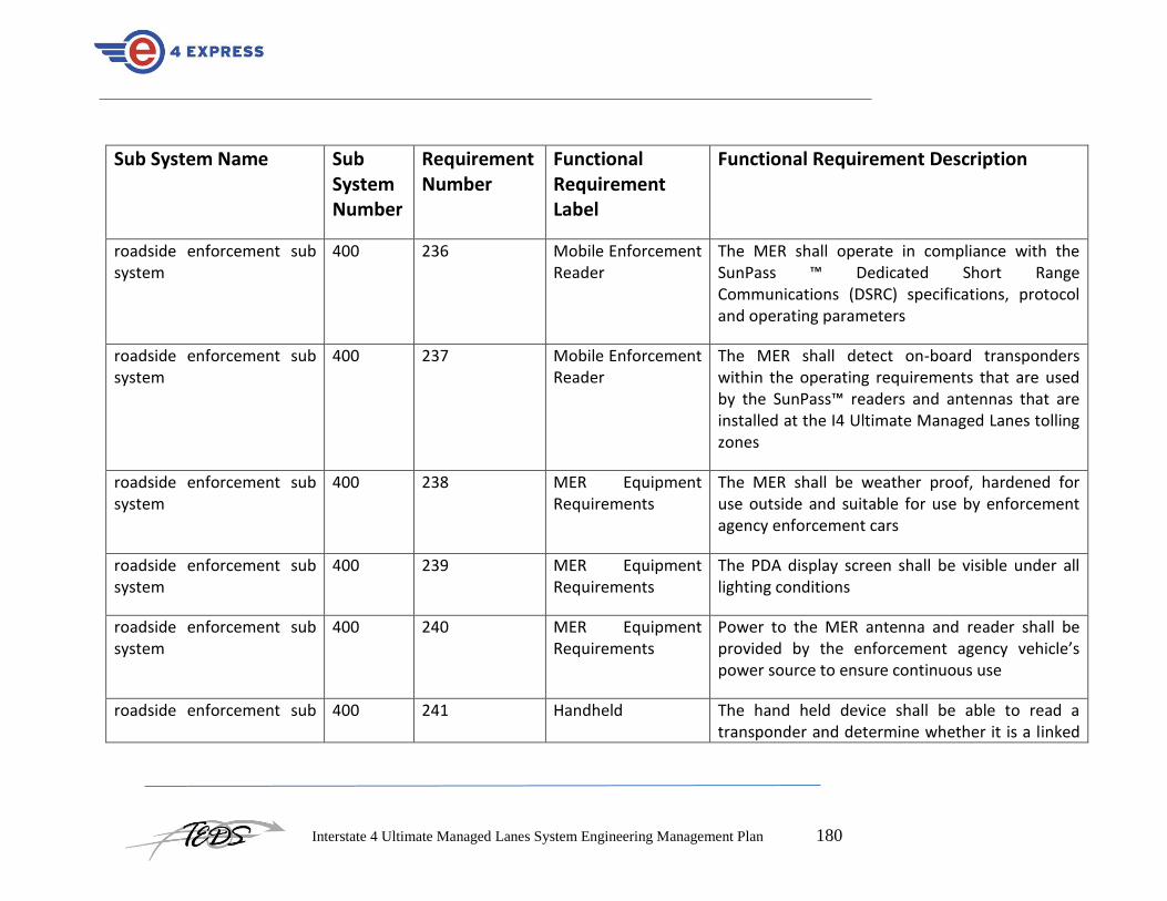
Interstate 4 Ultimate Managed Lanes System Engineering Management Plan 180
Sub System Name Sub System Number
Requirement Number
Functional Requirement Label
Functional Requirement Description
roadside enforcement sub system
400 236 Mobile Enforcement Reader
The MER shall operate in compliance with the SunPass ™ Dedicated Short Range Communications (DSRC) specifications, protocol and operating parameters
roadside enforcement sub system
400 237 Mobile Enforcement Reader
The MER shall detect on-board transponders within the operating requirements that are used by the SunPass™ readers and antennas that are installed at the I4 Ultimate Managed Lanes tolling zones
roadside enforcement sub system
400 238 MER Equipment Requirements
The MER shall be weather proof, hardened for use outside and suitable for use by enforcement agency enforcement cars
roadside enforcement sub system
400 239 MER Equipment Requirements
The PDA display screen shall be visible under all lighting conditions
roadside enforcement sub system
400 240 MER Equipment Requirements
Power to the MER antenna and reader shall be provided by the enforcement agency vehicle’s power source to ensure continuous use
roadside enforcement sub 400 241 Handheld The hand held device shall be able to read a transponder and determine whether it is a linked

Interstate 4 Ultimate Managed Lanes System Engineering Management Plan 181
Sub System Name Sub System Number
Requirement Number
Functional Requirement Label
Functional Requirement Description
system Enforcement Device to a SunPass™ account that is in good standing;
roadside enforcement sub system
400 242 Handheld Enforcement Device
The hand held device shall operate within the SunPass™ DSRC protocol and operating standards
roadside enforcement sub system
400 243 Hand Held Equipment Requirements
The hand held device shall be small enough in size, weather proof, hardened for use outside and suitable for use by a enforcement agency motorcycle officer
roadside enforcement sub system
400 244 Enforcement Use of Personal Digital Assistant Devices
PDAs shall be used in support of both the MER and hand held enforcement devices.
roadside enforcement sub system
400 245 Enforcement Use of Personal Digital Assistant Devices
The PDA shall provide enforcement agency officers with readily accessible information on transponder identification numbers and related customer descriptive information
roadside enforcement sub system
400 246 Enforcement Use of Personal Digital Assistant Devices
The PDA shall also receive tag status downloads on, at least, a daily basis

Interstate 4 Ultimate Managed Lanes System Engineering Management Plan 182
Sub System Name Sub System Number
Requirement Number
Functional Requirement Label
Functional Requirement Description
roadside enforcement sub system
400 247 Enforcement Use of Personal Digital Assistant Devices
The PDA shall receive tag status file data which includes the daily updated list of the valid and invalid transponders recognized by the FTE Tolls Back Office. This data shall be downloaded when the PDA is connected to the FTE Tolls Back Office system Wide Area Network (WAN
roadside enforcement sub system
400 248 Enforcement Use of Personal Digital Assistant Devices
The PDA shall receive tag status updates periodically throughout the day. This data shall be downloaded to the PDA over a secure, high-speed wireless communications connection
roadside enforcement sub system
400 249 Enforcement Use of Personal Digital Assistant Devices
The PDA will contain software to compare a transponder’s identification with the tag status file and determine if the transponder is linked to an account in good standing
roadside enforcement sub system
400 250 Enforcement Use of Personal Digital Assistant Devices
The PDA shall display information in an intuitive format that requires minimal interaction on the part of the user
roadside enforcement sub system
400 251 PDA Equipment Requirements
The PDA shall be small in size, weather proof, hardened for use outside and suitable for use by

Interstate 4 Ultimate Managed Lanes System Engineering Management Plan 183
Sub System Name Sub System Number
Requirement Number
Functional Requirement Label
Functional Requirement Description
enforcement agency motorcycle officers.
roadside enforcement sub system
400 252 PDA Equipment Requirements
The PDA display screen shall be visible under all lighting conditions
roadside enforcement sub system
400 253 PDA Equipment Requirements
The PDA shall be able to receive data over a secure, high-speed, wireless WAN connection
roadside enforcement sub system
400 254 PDA Equipment Requirements
A rechargeable battery shall power the PDA that allows use for up to 12 hours of continuous use
FTE Tolls Back Office 100 255 FTE Tolls Back Office Customer Service Center
The existing FTE Tolls Back Office shall be slightly modified, by FTE Tolls Back Office’s back office provider, to include I4 Ultimate Managed Lanes functionality
FTE Tolls Back Office 100 256 FTE Tolls Back Office Customer Service Center
The current business rules, procedures and practices of the FTE Tolls Back Office shall remain the same, but some changes will be necessary to accommodate the new I4 Ultimate Managed Lanes customers. One area in which changes will be required is to modify the FTE Tolls Back Office SunPass™ account statements to include I4

Interstate 4 Ultimate Managed Lanes System Engineering Management Plan 184
Sub System Name Sub System Number
Requirement Number
Functional Requirement Label
Functional Requirement Description
Ultimate Managed Lanes trips.
FTE Tolls Back Office 100 257 FTE Tolls Back Office Customer Service Center
Other changes are required to integrate the I4 Ultimate Managed Lanes operation into their back office processing, including agency codes, file names, etc.
FTE Tolls Back Office 100 258 FTE Tolls Back Office Customer Service Center
When accessing customer accounts, Customer Service Representatives (CSRs) shall be able to view I4 Ultimate Managed Lanes transactions as well as account information
FTE Tolls Back Office 100 259 FTE Tolls Back Office Customer Service Center
Current FTE Tolls Back Office SunPass™ customer statements shall be modified to include actual I4 Ultimate Managed Lanes trips that are made

Interstate 4 Ultimate Managed Lanes System Engineering Management Plan 185
Sub System Name Sub System Number
Requirement Number
Functional Requirement Label
Functional Requirement Description
Tolling Communications Network
1000 260 Tolling Zones to FTE Tolls Back Office
Due to the distances between the Tolling Zones and the FTE Tolls Back Office system and the relatively high costs associated with adding new underground infrastructure, the communication links between the Tolling Zones and the FTE Tolls Back Office system shall utilize existing FDOT fiber, leased data communication services or a wireless communication network solution.
Tolling Communications Network
1000 261 Tolling Zones to FTE Tolls Back Office
These communication links shall provide a minimum 1.5Mbps data rate and shall have a high level of availability (99.999%).
Tolling Communications Network
1000 262 Tolling Zone to Tolling Zone
Tolling Zone to Tolling Zone communication shall be used to provide a redundant or backup communications path to the Tolling Data Center should the primary communications path fail
Tolling Communications Network
1000 263 Intra Tolling Zone Intra Tolling communications is defined as the communications between the lane controller and the local field devices within the Tolling Zone. This includes the VDS, SunPass™ antenna and reader, DMS and CCTV cameras

Interstate 4 Ultimate Managed Lanes System Engineering Management Plan 186
Sub System Name Sub System Number
Requirement Number
Functional Requirement Label
Functional Requirement Description
Tolling Communications Network
1000 264 Intra Tolling Zone The coverage for any intra-TZ communications infrastructure is 0.5 mile per tolling zone
Tolling Communications Network
1000 265 Intra Tolling Zone Secure point to point wireless communication links shall be used. For non-line-of-sight situations, repeaters shall be used
Tolling Communications Network
1000 266 Intra Tolling Zone Where civil work is being undertaken within a Tolling Zone and it is practical to install underground infrastructure, or where conduit will be installed to provide electrical service to field devices, twisted pair cabling shall be used for low data rate applications and fiber optic cabling shall be used for high data rate applications
Tolling Communications Network
1000 267 FTE Tolls Back Office to Enforcement Devices
Communications between the FTE Tolls Back Office system and enforcement devices, including the MERs and the hand-held devices, shall utilize a secure, high-speed data connection to the PDA over a cellular data network
Tolling Communications Network
1000 268 FTE Tolls Back Office to Enforcement
The cellular data communications network shall provide uninterrupted coverage over the entire

Interstate 4 Ultimate Managed Lanes System Engineering Management Plan 187
Sub System Name Sub System Number
Requirement Number
Functional Requirement Label
Functional Requirement Description
Devices length of the project.
Tolling Communications Network
1000 269 FTE Tolls Back Office to Enforcement Devices
The cellular data communications network shall provide a minimum data rate of 128kbps
Tolling Communications Network
1000 270 FTE Tolls Back Office to Enforcement Devices
The communication link between the enforcement device and the FTE Tolls Back Office system shall utilize Virtual Private Network (VPN) tunneling to establish a secure and encrypted connection

Interstate 4 Ultimate Managed Lanes System Engineering Management Plan 188
Appendix M: Communications Management Plan

Interstate 4 Ultimate Managed Lanes System Engineering Management Plan 189
1 Introduction The purpose of the Communications Management Plan is to define the communication
requirements for the project and how information will be distributed. The Communications
Management Plan defines the following:
What information will be communicated—to include the level of detail and format
How the information will be communicated—in meetings, email, telephone, web portal,
etc.
When information will be distributed—the frequency of project communications both
formal and informal
Who is responsible for communicating project information
Communication requirements for all project stakeholders
What resources the project allocates for communication
How any sensitive or confidential information is communicated and who must authorize
this
How changes in communication or the communication process are managed
The flow of project communications
Any constraints, internal or external, which affect project communications
Any standard templates, formats, or documents the project must use for communicating
An escalation process for resolving any communication-based conflicts or issues
This Communications Management Plan sets the communications framework for this
project. It will serve as a guide for communications throughout the life of the project and
will be updated as communication needs change. This plan identifies and defines the roles
of persons involved in this project. It also includes a communications matrix which maps
the communication requirements of this project. An in-depth guide for conducting
meetings details the communications rules and how the meetings will be conducted,
ensuring successful meetings. A project team directory is included to provide contact
information for all stakeholders directly involved in the project.
2 Communications Management Approach The Project Manager will take a proactive role in ensuring effective communications on
this project. The communications requirements are documented in the Communications
Matrix presented in this document. The Communications Matrix will be used as the guide
for what information to communicate, who is to do the communicating, when to
communicate it and to whom to communicate.
As with most project plans, updates or changes may be required as the project progresses or
changes are approved. Changes or updates may be required due to changes in personnel,
scope, budget, or other reasons. Additionally, updates may be required as the project
matures and additional requirements are needed. The project manager is responsible for
managing all proposed and approved changes to the communications management plan.
Once the change is approved, the project manager will update the plan and supporting

Interstate 4 Ultimate Managed Lanes System Engineering Management Plan 190
documentation and will distribute the updates to the project team and all stakeholders. This
methodology is consistent with the project’s Change Management Plan and ensures that all
project stakeholders remain aware and informed of any changes to communications
management.
3 Communications Management Constraints All project communication activities will occur within the project’s approved budget,
schedule, and resource allocations. The project manager is responsible for ensuring that
communication activities are performed by the project team and without external resources
which will result in exceeding the authorized budget. Communication activities will occur
in accordance with the frequencies detailed in the Communication Matrix in order to ensure
the project adheres to schedule constraints. Any deviation of these timelines may result in
excessive costs or schedule delays and must be approved by the project sponsor.
FDOT D5 organizational policy states that where applicable, standardized formats and
templates must be used for all formal project communications. The details of these policy
requirements are provided in the section titled “Standardization of Communication” in this
document.
FDOT D5 organizational policy also states that only the District Secretary of
Transportation or higher level employee may authorize the distribution of confidential
information. The FDT D5 project manager is responsible for ensuring that approval is
requested and obtained prior to the distribution of any confidential information regarding
this project.
4 Stakeholder Communication Requirements As part of identifying all project stakeholders, the project manager will communicate with
each stakeholder in order to determine their preferred frequency and method of
communication. This feedback will be maintained by the project manager in the project’s
Stakeholder Register. Standard project communications will occur in accordance with the
Communication Matrix; however, depending on the identified stakeholder communication
requirements, individual communication is acceptable and within the constraints outlined
for this project.
In addition to identifying communication preferences, stakeholder communication
requirements must identify the project’s communication channels and ensure that
stakeholders have access to these channels. If project information is communicated via
secure means or through internal company resources, all stakeholders, internal and
external, must have the necessary access to receive project communications.
Once all stakeholders have been identified and communication requirements are
established, the project team will maintain this information in the project’s Stakeholder

Interstate 4 Ultimate Managed Lanes System Engineering Management Plan 191
Register and use this, along with the project communication matrix as the basis for all
communications.
5 Roles
5.1 Project Sponsor – FDOT D5 District Secretary of Transportation
The project sponsor is the champion of the project and has authorized the project by
signing the project charter. This person is responsible for the funding of the project and is
ultimately responsible for its success. Since the Project Sponsor is at the executive level
communications should be presented in summary format unless the Project Sponsor
requests more detailed communications.
5.2 Program Manager – FDOT D5
The Program Manager oversees the project at the portfolio level and owns most of the
resources assigned to the project. The Program Manager is responsible for overall program
costs and profitability as such they require more detailed communications than the Project
Sponsor.
5.3 Key Stakeholders – FTE, FDOT Central Office, FHWA, Selected
Concessionaire (Integrator)
Stakeholders include all individuals and organizations who are impacted by the project.
For this project we are defining a subset of the stakeholders as Key Stakeholders. These
are the stakeholders with whom we need to communicate with and are not included in the
other roles defined in this section. The Key Stakeholders includes executive management
with an interest in the project and key users identified for participation in the project.
5.4 Change Control Board
The Change Control Board is a designated group which is reviews technical specifications
and authorizes changes within the organizations infrastructure. Technical design
documents, user impact analysis and implementation strategies are typical of the types of
communication this group requires.
5.5 Customer
The customer for this project is FDOT D5 As the customer who will be accepting the final
deliverable of this project they will be informed of the project status including potential
impacts to the schedule for the final deliverable or the product itself.
5.6 Project Manager
The Project Manager has overall responsibility for the execution of the project. The Project
Manager manages day to day resources, provides project guidance and monitors and
reports on the projects metrics as defined in the Project Management Plan. As the person
responsible for the execution of the project, the Project Manager is the primary

Interstate 4 Ultimate Managed Lanes System Engineering Management Plan 192
communicator for the project distributing information according to this Communications
Management Plan.
5.7 Project Team
The Project Team is comprised of all persons who have a role performing work on the
project. The project team needs to have a clear understanding of the work to be completed
and the framework in which the project is to be executed. Since the Project Team is
responsible for completing the work for the project they played a key role in creating the
Project Plan including defining its schedule and work packages. The Project Team requires
a detailed level of communications which is achieved through day to day interactions with
the Project Manager and other team members along with weekly team meetings.
5.8 Steering Committee
The Steering Committee includes management representing the departments which make
up the organization. The Steering Committee provides strategic oversight for changes
which impact the overall organization. The purpose of the Steering Committee is to ensure
that changes within the organization are effected in such a way that it benefits the
organization as a whole. The Steering Committee requires communication on matters
which will change the scope of the project and its deliverables.
5.9 Technical Lead
The Technical Lead is a person on the Project Team who is designated to be responsible for
ensuring that all technical aspects of the project are addressed and that the project is
implemented in a technically sound manner. The Technical Lead is responsible for all
technical designs, overseeing the implementation of the designs and developing as-build
documentation. The Technical Lead requires close communications with the Project
Manager and the Project Team.

Interstate 4 Ultimate Managed Lanes System Engineering Management Plan 193
6 Project Team Directory The following table presents contact information for all persons identified in this
communications management plan. The email addresses and phone numbers in table 2 will
be used to communicate with these people.
Role Name Title Organization/ Department
Email Phone
Project Sponsor
Program Manager
Project Manager
Project Stakeholders
Customer
Project Team
Technical Lead
Table 2: Communications Directory
6.1 Communication Methods and Technologies
The project team will determine, in accordance with FDOT D5 organizational policy, the
communication methods and technologies based on several factors to include: stakeholder
communication requirements, available technologies (internal and external), and
organizational policies and standards.
The Integrator will as part of the RFP requirements, be directed to provide FDOT D5 with
a SharePoint (or functionally equivalent) platform within the PMO which all projects use to
provide updates, archive various reports, and conduct project communications. This
platform enables senior management, as well as stakeholders with compatible technology,
to access project data and communications at any point in time. SharePoint also provides
the ability for stakeholders and project team members to collaborate on project work and
communication.

Interstate 4 Ultimate Managed Lanes System Engineering Management Plan 194
For stakeholders who do not have the ability to access SharePoint, a web site will also be
established for the project. Access to the website will be controlled with a username and
password. Any stakeholders identified who are not able to access SharePoint will be issued
a unique username and password in order to access the web site. The project manager is
responsible for ensuring all project communications and documentation are copied to the
web site and that the content mirrors what is contained on the SharePoint platform.
FDOT D5 maintains software licenses for MS Project software. All project teams are
responsible for developing, maintaining, and communicating schedules using this software.
PERT Charts are the preferred format for communicating schedules to stakeholders. The
project schedule will be maintained on both the SharePoint platform and the project
website.
All project communication and documentation, in addition to being maintained on the
SharePoint platform and project website, will be archived on the internal FDOT D5 shared
drive which resides in the PMO program directory. Organizational naming conventions for
files and folder will be applied to all archived work.

Interstate 4 Ultimate Managed Lanes System Engineering Management Plan 195
Communications Matrix Table 3: Communications Requirements.
Communication Type
Objective of Communication
Medium Frequency Audience Owner Deliverable Format
Kickoff Meeting Introduce the project team and the project. Review project objectives and management approach.
Face to Face
Once Project Sponsor
Project Team
Stakeholders
Project Manager Agenda
Meeting Minutes
Soft copy archived on project SharePoint site and project web site
Project Team Meetings
Review status of the project with the team.
Face to Face
Conference Call
Weekly Project Team Project Manager Agenda
Meeting Minutes
Project schedule
Soft copy archived on project SharePoint site and project web site
Technical Design Meetings
Discuss and develop technical design solutions for the project.
Face to Face
As Needed Project Technical Staff
Technical Lead Agenda
Meeting Minutes
Soft copy archived on project SharePoint site and project web site
Monthly Project Status Meetings
Report on the status of the project to management.
Face to Face
Conference Call
Monthly PMO Project Manager Slide updates
Project schedule
Soft copy archived on project SharePoint site and project web site

Interstate 4 Ultimate Managed Lanes System Engineering Management Plan 196
Communication Type
Objective of Communication
Medium Frequency Audience Owner Deliverable Format
Project Status Reports
Report the status of the project including activities, progress, costs and issues.
Email Monthly Project Sponsor
Project Team
Stakeholders
PMO
Project Manager Project Status Report
Project schedule
Soft copy archived on project SharePoint site and project web site
.

Interstate 4 Ultimate Managed Lanes System Engineering Management Plan 197
7 Communication Flowchart The communication flowchart below was created to aid in project communication. This
flowchart provides a framework for the project team to follow for this project. However,
there may be occasions or situations which fall outside of the communication flowchart
where additional clarification is necessary. In these situations the Project Manager is
responsible for discussing the communication with the Project Sponsor and making a
determination on how to proceed.
Figure 14: communications Flow Chart
Regular project Communication?
Is Communication Confidential?
Meet with PM on nature of communication
Refer to communication matrix
Does PM or higher approve?
Meet with PM or higher
Distribute communication accordingly
YES
YES YES
NO
NO
NO

Interstate 4 Ultimate Managed Lanes System Engineering Management Plan 198
8 Guidelines for Meetings
8.1 Meeting Agenda
Meeting Agenda will be distributed 5 business days in advance of the meeting. The
Agenda should identify the presenter for each topic along with a time limit for that topic.
The first item in the agenda should be a review of action items from the previous meeting.
8.2 Meeting Minutes
Meeting minutes will be distributed within 2 business days following the meeting. Meeting
minutes will include the status of all items from the agenda along with new action items
and the Parking Lot list.
8.3 Action Items
Action Items are recorded in both the meeting agenda and minutes. Action items will
include both the action item along with the owner of the action item. Meetings will start
with a review of the status of all action items from previous meetings and end with a
review of all new action items resulting from the meeting. The review of the new action
items will include identifying the owner for each action item.
8.4 Meeting Chair Person
The Chair Person is responsible for distributing the meeting agenda, facilitating the
meeting and distributing the meeting minutes. The Chair Person will ensure that the
meeting starts and ends on time and that all presenters adhere to their allocated time
frames.
8.5 Note Taker
The Note Taker is responsible for documenting the status of all meeting items, maintaining
a Parking Lot item list and taking notes of anything else of importance during the meeting.
The Note Taker will give a copy of their notes to the Chair Person at the end of the meeting
as the Chair Person will use the notes to create the Meeting Minutes.
8.6 Time Keeper
The Time Keeper is responsible for helping the facilitator adhere to the time limits set in
the meeting agenda. The Time Keeper will let the presenter know when they are
approaching the end of their allocated time. Typically a quick hand signal to the presenter
indicating how many minutes remain for the topic is sufficient.
8.7 Parking Lot
The Parking Lot is a tool used by the facilitator to record and defer items which aren’t on
the meeting agenda; however, merit further discussion at a later time or through another
forum.

Interstate 4 Ultimate Managed Lanes System Engineering Management Plan 199
A parking lot record should identify an owner for the item as that person will be
responsible for ensuring follow-up. The Parking Lot list is to be included in the meeting
minutes.
9 Communication Standards For this project, FDOT D5 will utilize standard organizational formats and templates for all
formal project communications. Formal project communications are detailed in the
project’s communication matrix and include:
9.1 Kickoff Meeting
Pproject team will utilize FDOT D5 standard templates for meeting agenda and meeting
minutes. Additionally, any slides presented will use the FDOT D5 standard slideshow
template.
9.2 Project Team Meetings
Project team will utilize FDOT D5 standard templates for meeting agenda and meeting
minutes. Additionally, any slides presented will use the FDOT D5 standard slideshow
template.
9.3 Technical Design Meetings
Project team will utilize FDOT D5 standard templates for meeting agenda and meeting
minutes. Additionally, any slides presented will use the FDOT D5 standard slideshow
template.
9.4 Monthly Project Status Meetings
Project team will utilize FDOT D5 standard templates for meeting agenda and meeting
minutes. Additionally, any slides presented will use the FDOT D5 standard slideshow
template.
9.5 Project Status Reports
Project team will utilize FDOT D5 standard templates for meeting agenda and meeting
minutes. Additionally the standard project status report document, available on the share
drive, will be used to provide project status.
Informal project communications should be professional and effective but there is no
standard template or format that must be used.

Interstate 4 Ultimate Managed Lanes System Engineering Management Plan 200
10 Communication Escalation Process Efficient and timely communication is the key to successful project completion. As such, it
is imperative that any disputes, conflicts, or discrepancies regarding project
communications are resolved in a way that is conducive to maintaining the project
schedule, ensuring the correct communications are distributed, and preventing any ongoing
difficulties. In order to ensure projects stay on schedule and issues are resolved, FDOT D5
will use its standard escalation model to provide a framework for escalating
communication issues. Table 4 below defines the priority levels, decision authorities, and
timeframes for resolution.
Table 4: Communications Escalation Process
Any communication including sensitive and/or confidential information will require
escalation to District Secretary level or higher for approval prior to external distribution.
Priority Definition Decision Authority
Timeframe for Resolution
Priority 1 Major impact to project or business operations. If not resolved quickly there will be a significant adverse impact to revenue and/or schedule.
District Secretary of Transportation or higher
Within 4 hours
Priority 2 Medium impact to project or business operations which may result in some adverse impact to revenue and/or schedule.
Project Sponsor
Within one business day
Priority 3 Slight impact which may cause some minor scheduling difficulties with the project but no impact to business operations or revenue.
Project Manager
Within two business days
Priority 4 Insignificant impact to project but there may be a better solution.
Project Manager
Work continues and any recommendations are submitted via the project change control process

Interstate 4 Ultimate Managed Lanes System Engineering Management Plan 201
Appendix N: Procurement Management Plan

Interstate 4 Ultimate Managed Lanes System Engineering Management Plan 202
1 Introduction The purpose of the Procurement Management Plan is to define the procurement
requirements for the I-4 Managed Lanes Project and how it will be managed from
developing procurement documentation through contract closure. The Procurement
Management Plan defines the following:
Items to be procured with justification statements and timelines
Type of contract to be used
Risks associated with procurement management
How procurement risks will be mitigated through contract performance metrics, insurance,
or other means
Determining costs and if/how they’re used as evaluation criteria
Any standardized procurement templates or documents to be used
How multiple suppliers will be managed if applicable
Contract approval process
Decision criteria
Establishing contract deliverables and deadlines
How procurement and contracts are coordinated with project scope, budget, and schedule
Any constraints pertaining to procurement
Direction to sellers on baseline requirements such as contract schedules and work
breakdown structures (WBSs)
Integrator Management
Identification of any prequalified sellers if applicable
Performance metrics for procurement activities
This Procurement Management Plan sets the procurement framework for this project. It
will serve as a guide for managing procurement throughout the life of the I-4 Managed
Lanes Project and will be updated as acquisition needs change. This plan identifies and
defines the items to be procured, the types of contracts to be used in support of this project,
the contract approval process, and decision criteria. The importance of coordinating
procurement activities, establishing firm contract deliverables, and metrics in measuring
procurement activities is included. Other items included in the procurement management
plan include: procurement risks and procurement risk management considerations; how
costs will be determined; how standard procurement documentation will be used; and
procurement constraints.
2 Procurement Management Approach The FDOT D5 FDOT D5 Project Manager will provide oversight and management for all
procurement activities under this project. The FDOT D5 Project Manager will work with
the I-4 Managed Lanes Project team to identify all items to be procured for the successful
completion of the I-4 Managed Lanes Project. The Project Management Office (PMO) will
then review the procurement list prior to submitting it to the contracts and purchasing
department. The contracts and purchasing department will review the procurement items,

Interstate 4 Ultimate Managed Lanes System Engineering Management Plan 203
determine whether it is advantageous to make or buy the items, and begin the Integrator
selection, purchasing and the contracting process.
3 Procurement Definition The following procurement items and/or services have been determined to be essential for
project completion and success. The following list of items/services, justification, and
timeline are pending PMO review for submission to the contracts and purchasing
department:
ID Item/Service Justification Needed By
A Electronic toll collection and pricing system
B ITS
In addition to the above list of procurement items, the following individuals are authorized
to approve purchases for the I-4 Managed Lanes Project team:
Name Role
4 Type of Contract to be used All items and services to be procured for this project will be solicited under the auspices of
a Public Private Partnership agreement that will be competitively bid as a public
procurement. The project team will work with the contracts and purchasing department to
define and RFP for the procurement of the services. The contracts and purchasing
department will then solicit bids from various concessionaires in order to procure the items
within the required time frame and at a reasonable cost under the firm fixed price contract
once the concessionaire is selected. This contract will be awarded with an xx year
concession term with agreed availability payments..

Interstate 4 Ultimate Managed Lanes System Engineering Management Plan 204
5 Procurement Risks All procurement activities carry some potential for risk which must be managed to ensure
project success. While all risks will be managed in accordance with the I-4 Managed Lanes
Project’s risk management plan, there are specific risks which pertain specifically to
procurement which must be considered:
• Unrealistic schedule and cost expectations for concessionaires
• Construction capacity capabilities of concessionaires
• Conflicts with current contracts and Integrator relationships
• Configuration management for upgrades and improvements of purchased technology
• Potential delays in shipping and impacts on cost and schedule
• Questionable past performance for Integrators
• Potential that final product does not meet required specifications
These risks are not all-inclusive and the standard risk management process of identifying,
documenting, analyzing, mitigating, and managing risks will be used.
6 Procurement Risk Management As previously stated, project risks will be managed in accordance with the I-4 Managed
Lanes Project’s risk management plan. However, for risks related specifically to
procurement, there must be additional consideration and involvement. Project procurement
efforts involve external organizations and potentially affect current and future business
relationships as well as internal supply chain and Integrator management operations.
Because of the sensitivity of these relationships and operations the I-4 Managed Lanes
Project team will include the I-4 Managed Lanes Project sponsor and a designated
representative from the contracting department in all project meetings and status reviews.
Additionally, any decisions regarding procurement actions must be approved by the I-4
Managed Lanes Project sponsor before implementation. Any issues concerning
procurement actions or any newly identified risks will immediately be communicated to the
I-4 Managed Lanes Project’s contracting department point of contact as well as the I-4
Managed Lanes Project sponsor.
7 Cost Determination For this project we will issue a Request for Proposal (RFP) in order to solicit proposals
from concessionaire teams which describe how they will meet our requirements and the
cost of doing so. All proposals will include Integrator support for items in the RFP as well
as the base and out-year costs. The Integrators will outline how the work will be
accomplished, who will perform the work, Integrators’ experience in providing these
goods, customer testimonials, backgrounds and resumes of employees performing the
work, and a line-item breakdown of all costs involved. Additionally, the Integrators will be
required to submit work breakdown structures (WBSs) and work schedules to show their

Interstate 4 Ultimate Managed Lanes System Engineering Management Plan 205
understanding of the work to be performed and their ability to meet the I-4 Managed Lanes
Project schedule.
All information must be included in each proposal as the proposals will be used as the
foundation of our selection criteria. Proposals which omit solicited information or contain
incomplete information will be discarded from consideration.
8 Standardized Procurement Documentation The procurement management process consists of many steps as well as ongoing
management of all procurement activities and contracts. In this dynamic and sensitive
environment, our goal must be to simplify procurement management by all necessary
means in order to facilitate successful completion of our contracts and project. To aid in
simplifying these tasks, we will use standard documentation for all steps of the
procurement management process. These standard documents have been developed and
revised over a period of many years in an effort to continually improve procurement
efforts. They provide adequate levels of detail which allows for easier comparison of
proposals, more accurate pricing, more detailed responses, and more effective management
of contracts and Integrators.
The PMO maintains a repository on the company’s shared drive which contains standard
project management and procurement documentation that will be used for this project. The
following standard documents will be used for project procurement activities:
Standard Request for Proposal Template to include:
• Background
• Proposal process and timelines
• Proposal guidelines
• Proposal formats and media
• Source selection criteria
• Pricing forms
• Statement of work
• Terms and Conditions
• Internal source selection evaluation forms
• Non-disclosure agreement
• Letter of intent
• Firm fixed price contract
• Procurement audit form
• Procurement performance evaluation form
• Lessons learned form

Interstate 4 Ultimate Managed Lanes System Engineering Management Plan 206
9 Procurement Constraints There are several constraints that must be considered as part of the I-4 Managed Lanes
Project’s procurement management plan. These constraints will be included in the RFP
and communicated to all Integrators in order to determine their ability to operate within
these constraints. These constraints apply to several areas which include schedule, cost,
scope, resources, and technology:
9.1 Schedule:
Project schedule is not flexible and the procurement activities, contract administration, and
contract fulfillment must be completed within the established project schedule.
9.2 Cost:
Project budget has contingency and management reserves built in; however, these reserves
may not be applied to procurement activities. Reserves are only to be used in the event of
an approved change in project scope or at management’s discretion.
9.3 Scope:
All procurement activities and contract awards must support the approved project scope
statement. Any procurement activities or contract awards which specify work which is not
in direct support of the I-4 Managed Lanes Project’s scope statement will be considered
out of scope and disapproved.
9.4 Resources:
All procurement activities must be performed and managed with current personnel. No
additional personnel will be hired or re-allocated to support the procurement activities on
this project.
9.5 Technology:
Parts specifications have already been determined and will be included in the statement of
work as part of the RFP. While proposals may include suggested alternative material or
manufacturing processes, parts specifications must match those provided in the statement
of work exactly.
10 Contract Approval Process The first step in the contract approval process is to determine what items or services will
require procurement from outside Integrators. This will be determined by conducting a
cost analysis on products or services which can be provided internally and compared with
purchase prices from Integrators. Once cost analyses are complete and the list of items and
services to be procured externally is finalized, the purchasing and contracts department will
send out solicitations to outside Integrators. Once solicitations are complete and proposals
have been received by all Integrators the approval process begins. The first step of this

Interstate 4 Ultimate Managed Lanes System Engineering Management Plan 207
process is to conduct a review of all Integrator proposals to determine which meet the
criteria established by the I-4 Managed Lanes Project team and the purchasing and
contracts department. Purchases less than the Project Manager’s spending limit only
require the approval of the FDOT D5 Project Manager; whereas, purchases greater than the
Project Manager’s spending limit must be approved by the Contract Review Board. For
these larger purchases the contract review board will meet to determine which contract will
be accepted. The Contract Review Board consists of representatives from the I-4 Managed
Lanes Project team, purchasing and contracts department, finance, and the PMO.
11 Decision Criteria The criteria for the selection and award of procurement contracts under this project will be
based on the following decision criteria:
• Ability of the Integrator to provide all items by the required delivery date
• Quality
• Cost
• Expected delivery date
• Comparison of outsourced cost versus in-sourcing
• Past performance
These criteria will be measured by the contracts review board and/or the FDOT D5 Project
Manager. The ultimate decision will be made based on these criteria as well as available
resources.
12 Integrator Management The FDOT D5 Project Manager is ultimately responsible for managing Integrators. In
order to ensure the timely delivery and high quality of products from Integrators the FDOT
D5 Project Manager, or his/her designee will meet weekly with the contract and purchasing
department and each Integrator to discuss the progress for each procured item. The
meetings can be in person or by teleconference. The purpose of these meetings will be to
review all documented specifications for each product as well as to review the quality test
findings. This forum will provide an opportunity to review each item’s development or the
service provided in order to ensure it complies with the requirements established in the I-4
Managed Lanes Project specifications. It also serves as an opportunity to ask questions or
modify contracts or requirements ahead of time in order to prevent delays in delivery and
schedule. The FDOT D5 Project Manager will be responsible for scheduling this meeting
on a weekly basis until all items are delivered and are determined to be acceptable.

Interstate 4 Ultimate Managed Lanes System Engineering Management Plan 208
13 Performance Metrics for Procurement Activities While the purchasing and contracts department has their own internal metrics for
procurement, the following metrics are established for Integrator performance for this
project’s procurement activities. Each metric is rated on a 1-3 scale as indicated below:
Integrator Product Quality
On Time Delivery
Documentation Quality
Development Costs
Development Time
Cost per Unit
Transactional Efficiency
Integrator #1
Integrator #2
1 – Unsatisfactory
2 – Acceptable
3 - Exceptional
In addition to rating each Integrator, actual values will be noted in order to build a past-
performance data base for selecting Integrators for future procurement activities.