I 12d Ascii File Format - Civil Engineering · I 12d Ascii File Format ... This extra data is...
42
March 2011 Page 4043 General Comments about 12d Ascii File I 12d Ascii File Format The 12d Ascii file format (called 4D Ascii in Version 4 and earlier) is a text file definition from 12D Solutions which is used for reading and writing out string data from 12d Model. 12d Ascii files normally end in ’ .12da’ This document is for the 12d Ascii file format used in 12d Model Version 9. For General Comments about 12da, go to the section “General Comments about 12d Ascii File” For the 12da definitions of Attributes go to “Attributes” Commands “Commands” 12d string types “12d Ascii Definition for each String Type” 12d tins “12d Ascii Definition for Tins” 12d plot frames “12d Ascii Definition for Plot Frames” General Comments about 12d Ascii File // Anything written on a line after // is ignored. This is used to place comments in the file. Blank lines Unless they are part of a text string, blank lines are ignored. Spaces Unless enclosed in quotes ("), more than one consecutive space or tab is treated as one space. Except when it is the delimiter after a //, an end of line (<enter>) is also considered a space. Spaces and special characters in text strings Any text string that includes spaces and any characters other than a to z, A to Z or 0 to 9 (alphanumeric), must be enclosed in double quotes. In text strings, double quotes " and backslash \ must be preceded by a \. For example, \" and \\ define a " and a \ respectively in a text string. Names of models, tins, styles, colours and attributes Models, tins, styles (linestyles), colours and attributes can include the characters a to z, A to Z, 0 to 9 (alphanumeric characters) and space. Leading and trailing spaces are ignored. The names can be up to 255 characters in length. If the name includes spaces, the name must be enclosed in double quotes ("). The names for models, tins, styles, colours or attributes can not be blank. The names for models, tins, styles and colours can contain upper and lower alpha characters which are stored, but the set of model names, tin names, style names, colour names or attribute names for an object must be unique when case is ignored. For example, the model name "Fred" will be stored as "Fred" but "FRED" is considered to be the same model name as "Fred". String names String names can include the characters a to z, A to Z, 0 to 9 (alphanumeric characters), space, decimal point (.), plus (+), minus (-), comma (,), open and closed round brackets and
Transcript of I 12d Ascii File Format - Civil Engineering · I 12d Ascii File Format ... This extra data is...

I 12d Ascii File FormatThe 12d Ascii file format (called 4D Ascii in Version 4 and earlier) is a text file definition from 12D Solutions which is used for reading and writing out string data from 12d Model. 12d Ascii files normally end in ’.12da’
This document is for the 12d Ascii file format used in 12d Model Version 9.
For General Comments about 12da, go to the section “General Comments about 12d Ascii File”
For the 12da definitions of Attributes go to “Attributes” Commands “Commands” 12d string types “12d Ascii Definition for each String Type” 12d tins “12d Ascii Definition for Tins” 12d plot frames “12d Ascii Definition for Plot Frames”
General Comments about 12d Ascii File//
Anything written on a line after // is ignored. This is used to place comments in the file.
Blank lines
Unless they are part of a text string, blank lines are ignored.
Spaces
Unless enclosed in quotes ("), more than one consecutive space or tab is treated as one space. Except when it is the delimiter after a //, an end of line (<enter>) is also considered a space.
Spaces and special characters in text strings
Any text string that includes spaces and any characters other than a to z, A to Z or 0 to 9 (alphanumeric), must be enclosed in double quotes. In text strings, double quotes " and backslash \ must be preceded by a \. For example, \" and \\ define a " and a \ respectively in a text string.
Names of models, tins, styles, colours and attributes
Models, tins, styles (linestyles), colours and attributes can include the characters a to z, A to Z, 0 to 9 (alphanumeric characters) and space. Leading and trailing spaces are ignored. The names can be up to 255 characters in length. If the name includes spaces, the name must be enclosed in double quotes (").
The names for models, tins, styles, colours or attributes can not be blank.
The names for models, tins, styles and colours can contain upper and lower alpha characters which are stored, but the set of model names, tin names, style names, colour names or attribute names for an object must be unique when case is ignored. For example, the model name "Fred" will be stored as "Fred" but "FRED" is considered to be the same model name as "Fred".
String names
String names can include the characters a to z, A to Z, 0 to 9 (alphanumeric characters), space, decimal point (.), plus (+), minus (-), comma (,), open and closed round brackets and
March 2011 Page 4043General Comments about 12d Ascii File

12d Model Reference Manual
equals (=). Leading and trailing spaces are ignored. String names can be up to 255 characters in length. If the string name includes anything other than alphanumeric characters, then the name must be enclosed in double quotes (").
String can contain upper and lower alpha characters which are retained but case is ignored when selecting by string name. That is, the string name "Fred" will be stored as "Fred" but "FRED" is not considered to be a different name.
String names do not have to be unique and can be blank.
Please continue to the next section “Attributes” .
Page 4044 March 2011General Comments about 12d Ascii File
Appendix I
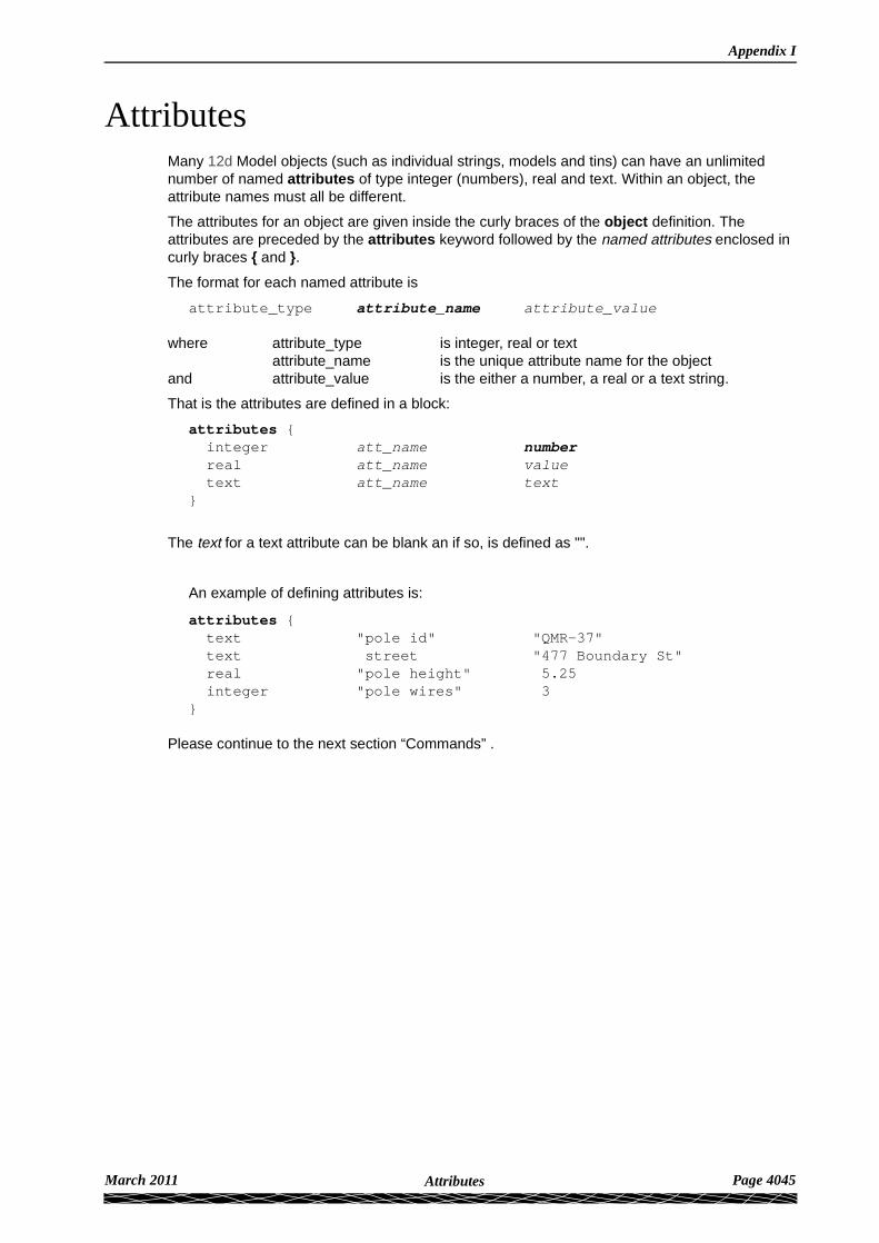
AttributesMany 12d Model objects (such as individual strings, models and tins) can have an unlimited number of named attributes of type integer (numbers), real and text. Within an object, the attribute names must all be different.
The attributes for an object are given inside the curly braces of the object definition. The attributes are preceded by the attributes keyword followed by the named attributes enclosed in curly braces { and }.
The format for each named attribute is
attribute_type attribute_name attribute_value
where attribute_type is integer, real or textattribute_name is the unique attribute name for the object
and attribute_value is the either a number, a real or a text string.
That is the attributes are defined in a block:
attributes { integer att_name number real att_name value text att_name text}
The text for a text attribute can be blank an if so, is defined as "".
An example of defining attributes is:
attributes {text "pole id" "QMR-37"text street "477 Boundary St"real "pole height" 5.25integer "pole wires" 3
}
Please continue to the next section “Commands” .
March 2011 Page 4045Attributes
12d Model Reference Manual
CommandsCommands consist of a keyword followed by a space and then a value (a keyword and its value is often referred to as a keyword pair). A value must always exist.
keyword value // a keyword pair
There can be more than on command keyword pair per line as long as each keyword pair is separated by a space. In fact, the keyword can be on one line and the value on the next line.
Although the names of commands are only shown in lower case in these notes, commands are case insensitive and all combinations of case are recognised as the same command. That is ’model’, ’MODEL’ and ’ModeL’ are all recognised as the command ’model’.
The commands in the 12d Ascii file are:
model model_name // system default data
All strings following until the next model keyword are placed in the model model_name. This can be overridden for a string by a model command inside the string definition.
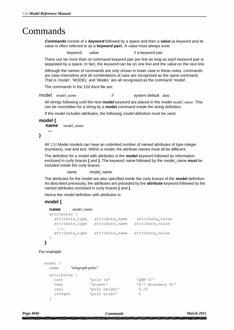
If the model includes attributes, the following model definition must be used.
model { name model_name ...}
All 12d Model models can have an unlimited number of named attributes of type integer (numbers), real and text. Within a model, the attribute names must all be different.
The definition for a model with attributes is the model keyword followed by information enclosed in curly braces { and }. The keyword name followed by the model_name must be included inside the curly braces.
name model_name
The attributes for the model are also specified inside the curly braces of the model definition. As described previously, the attributes are preceded by the attribute keyword followed by the named attributes enclosed in curly braces { and }.
Hence the model definition with attributes is:
model {
name model_nameattributes {
attribute_type attribute_name attribute_value attribute_type attribute_name attribute_value ... attribute_type attribute_name attribute_value}
}
For example:
model {name "telegraph poles"
attributes {text "pole id" "QMR-37"text "street" "477 Boundary St"real "pole height" 5.25integer "pole wires" 3
}
Page 4046 March 2011Commands

Appendix I
}
colour colour_name // system default red
All strings following until the next colour keyword have colour colour_name. This can be overridden for a string by a colour command in the string definition.
style style_name // system default 1
All strings following until the next style keyword have style style_name. This can be overridden for a string by a style command in the string definition.
breakline point or line // system default line
All strings following that requires a breakline point-line type until the next breakline keyword, have this point-line type. This may be overridden for the string by a breakline in the string definition.
null value // system default -999
All z-values equal to value in strings following until the next null keyword, are considered to be null z-values.
string string_type { ...}
The string_type is compulsory and must be followed by all the string information enclosed in curly braces { and }.
Thus if a string type or possibly information inside the string is not recognised, the 12d Ascii reader has a chance of being able to jump over the string by looking for the end marker }.
Inside the braces are string commands as keyword pairs defining some information for the string.
There can be more than one string command keyword pair per line as long as each keyword pair is separated by a space. In fact, the keyword can be on one line and the value on the next line.
Any unrecognized string commands are ignored.
The string command keyword pairs include model, colour, style and breakline which are all optional inside the string definition. However if any of them exist inside a string definition, then the string command keyword overrides any model, colour, style or breakline commands but only for that particular string.
For some string types (e.g. 2d, 3d, pipe) there is more data required than just the string command keyword pairs.
This extra data is contained is blocks consisting of a keyword followed by the required information enclosed in curly braces { and }. For example attributes for all string types and (x,y) data for a 2d string.
For all string types, if there is not enough recognised information to define the string, the string is ignored.
The definition of each string type and the allowed string commands and extra data for that string type will be given after the next section on string attributes.
string attributes All 12d Model strings can have an unlimited number of named attributes of type integer (numbers), real and text. Within a string, the attribute names must all be different.The attributes for a string are given inside the curly braces of the string definition. As described previously, the attributes are preceded by the attributes keyword followed by the named attributes enclosed in curly braces { and }.
Please continue to the next section “12d Ascii Definition for each String Type” .
March 2011 Page 4047Commands

12d Model Reference Manual
12d Ascii Definition for each String TypeFor the 12da definitions of 2d string go to “2d String”
3d string “3d String” 4d string “4d String” Alignment string “Alignment String” Arc string “Arc String” 3d string “4d String” drainage string “Drainage String” face string “Face String” feature string “Feature String” interface string “Interface String” pipe string “Pipe String” polyline string “Polyline String” text string “Text String” super string “Super String” super alignment string “Super Alignment String”
2d Stringstring 2d {z value chainage start_chainagemodel model_name name string_namecolour colour_name style style_namebreakline point or linedata { // keyword
x-value y-value " " " "}
}
3d Stringstring 3d {chainage start_chainagemodel model_name name string_namecolour colour_name style style_namebreakline point or linedata { // keyword
x-value y-value z-value " " " " " "}
}
4d Stringstring 4d {angle value offset value raise value
Page 4048 March 201112d Ascii Definition for each String Type
Appendix I
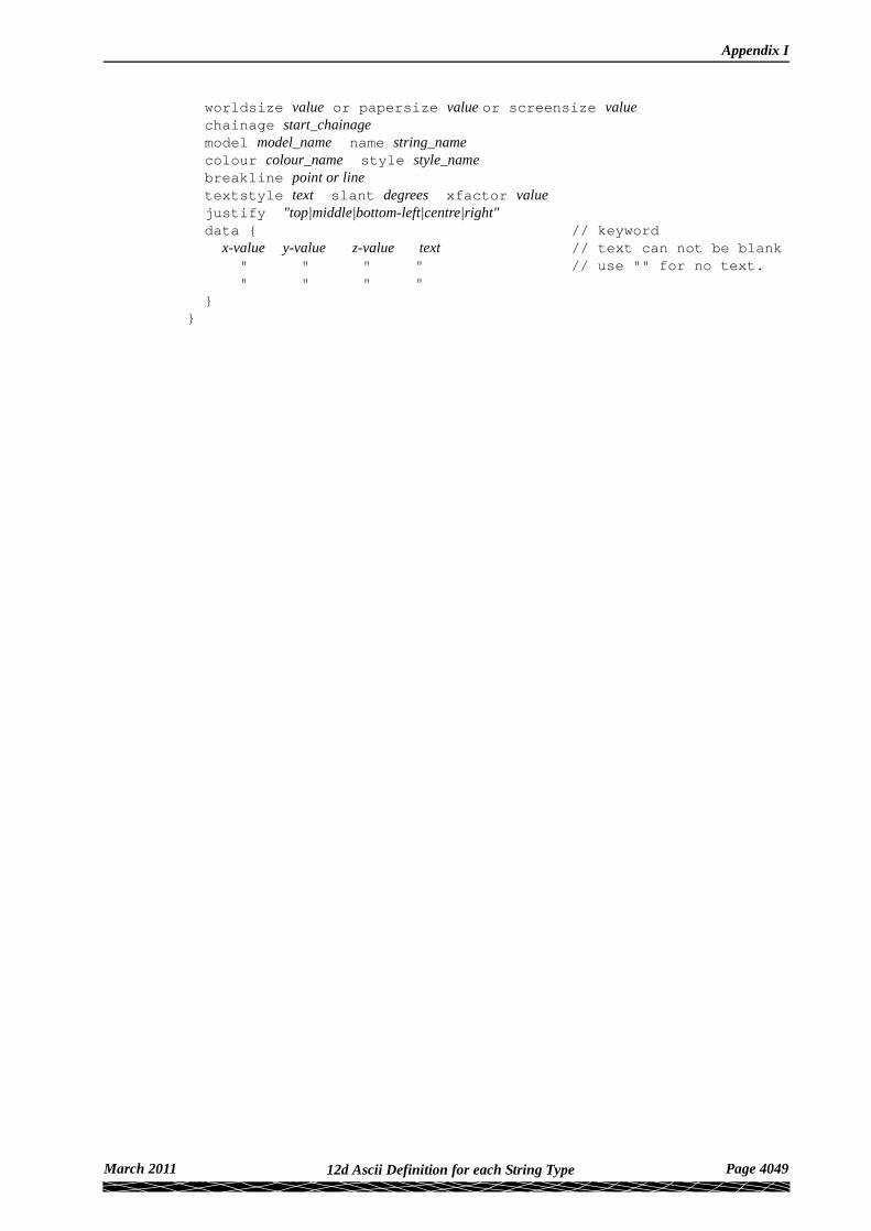
worldsize value or papersize value or screensize valuechainage start_chainagemodel model_name name string_namecolour colour_name style style_namebreakline point or linetextstyle text slant degrees xfactor valuejustify "top|middle|bottom-left|centre|right"data { // keyword
x-value y-value z-value text // text can not be blank " " " " // use "" for no text. " " " "
}}
March 2011 Page 404912d Ascii Definition for each String Type

12d Model Reference Manual
.
l
Alignment StringIn an alignment string the horizontal and vertical geometry are given separately and both can only be defined by the intersection point method (IP’s).
For the horizontal geometry, the (x,y) position of the horizontal intersection points (HIPs) are given in the order that they appear in the string, plus the circular radius and left and right transition lengths on each HIP.
Hence a horizontal intersection point is given by either
x-value y-value radius // circular curve, no transitionor
x-value y-value radius spil1 left-transition-length spil2 right-transition-length
radius, left-transition-length, right-transition-length can be zero (meaning they don't exist).
For the vertical geometry, the (chainage,height) position of the vertical intersection points (VIPs) are given in increasing chainage order, plus either the radius of the circular arc or the length of the parabolic curve on each VIP.
Hence for a vertical intersection point is given by either
ch_value z-value length parabola or
ch_value z-value radius circlewhere
the word parabola is optional. length and radius can be zero, meaning that the parabola or arc doesn't exist.
string alignment {model model_name name string_namecolour colour_name style style_namechainage start_chainage interval valuedraw_mode value // 1 to draw crosses at HIPs and VIPs, 0 don’t draw spiral_type text // spiral_type covers both spiral and non-spiral transitions
// For an alignment string, the supported transition types// are clothoid, cubic parabola, westrail-cubic, cubic spira// More transition are supported in the super alignment//
hipdata { // some hips must exist and precede the VIP data x-value y-value radius // or x-value y-value radius spil1 left-transition-length spil2 right-transition-length " " " " " " "}vipdata { // vips optional
ch_value z-value parabolic-length // or ch_value z-value parabolic-length parabola // or ch_value z-value radius circle " " " "}
}
Page 4050 March 201112d Ascii Definition for each String Type

Appendix I
Arc Stringstring arc {
model model_name name string_namecolour colour_name style style_namechainage start_chainage interval value radius valuexcentre value ycentre value zcentre valuexstart value ystart value zstart value xend value yend value zend value
}
Circle Stringstring circle {
model model_name name string_namecolour colour_name style style_namechainage start_chainage interval value radius valuezcentre value xcentre value ycentre value
}
Drainage Stringstring drainage {
chainage start_chainagemodel model_name name string_namecolour colour_name style style_namebreakline point or lineattributes {
text Tin finished_surface_tintext NSTin natural_surface_tininteger "_floating" 1|0 // 1 for floating, 0 not floating
}outfall outfall_value // z-value at the outfallflow_direction 0|1 // 0 drainage line is defined from downstream
// to upstream
data { // key word - geometry of the drainage string x-value y-value z-value radius bulge " " " " " "
}pit { // pit/manhole - one pit record for each pit/manhole
// in the order along the string name text // pit name type text // pit type road_name text // road name road_chainage chainage // road chainage diameter value // pit diameter floating yes|no // is pit floating or not chainage pit_chainage // internal use only ip value // internal use only ratio value // internal use only x x-value // x-value of top of pit y y-value // y-value of top of pit z z-value // z-value of top of pit
}
March 2011 Page 405112d Ascii Definition for each String Type
12d Model Reference Manual
pipe { // one pipe record for each pipe connecting pits/manholes// in the order they occur along the string
name text // pipe name type text // pipe type diameter value // pit diameter us_level value // ds_level value // us_hgl value // ds_hgl value // flow_velocity value // flow_volume value // }property_control {
name text // lot name colour colour_name grade value // grade of pipe in units of "1v in" cover value // cover of the of pipe diameter value // diameter of the of pipe boundary value // boundary trap value chainage chainage // internal use only ip value // internal use only ratio value // internal use only x x-value // x value of where pipe connects to sewer y y-value // y value of where pipe connects to sewer z z-value // internal use only
data { // key word - geometry of the property control x-value y-value z-value radius bulge " " " " " "}house_connection { // warning - house connections may change in future versions
name text // house connection name hcb integer // user given integer colour colour_name grade value // grade of connection in units of "1v in" depth value diameter value side left or right length value type text // connection type material text // material type bush text // bush type level value adopted_level value chainage chainage // internal use only ip value // internal use only ratio value // internal use only x x-value // x value of where pipe connects to sewer y y-value // y value of where pipe connects to sewer z z-value // internal use only}
} // end of drainage-sewer data
Face String
Page 4052 March 201112d Ascii Definition for each String Type

Appendix I
string face {model model_name name string_namecolour colour_name style style_namechainage start_chainage breakline point or linehatch_angle valuehatch_distance valuehatch_colour colouredge_colour colourfill_mode 0 or 1edge_mode 0 or 1data { // keyword
x-value y-value z-value " " "
}}
Feature Stringstring feature {
model model_name name string_namecolour colour_name style style_namechainage start_chainage interval value radius valuezcentre value xcentre value ycentre value
}
Interface Stringstring interface {
chainage start_chainagemodel model_name name string_namecolour colour_name style style_namebreakline point or linedata { // keyword
x-value y-value z-value mode " " " " // mode = -1 cut " " " " // 0 surface
} // 1 fill}
Pipe Stringstring pipe {
diameter value chainage start_chainagemodel model_name name string_namecolour colour_name style style_namebreakline point or linedata { // keyword
x-value y-value z-value " " " " " "
}}
Pipeline String
March 2011 Page 405312d Ascii Definition for each String Type

12d Model Reference Manual
This is the same as an alignment string except that it has the additional keywords
diameter, which gives the diameter of the pipeline in world unitsand
length of the typical pipe making up the pipeline (used for deflections).
string pipeline {model model_name name string_namecolour colour_name style style_namediameter diameter length pipe-lengthchainage start_chainage interval valuespiral_type text // spiral_type covers both spiral and non-spiral transitions
// supported by 12d. For an alignment string, the// supported transition types are clothoid, cubic parabola,// westrail-cubic, cubic spiral. Other transition types// are supported in the super alignment
hipdata { // some hips must exist and precede vips x-value y-value radius // or x-value y-value radius spil1 left-transition-length spil2 right-transition-length " " " " " " "}vipdata { // vips optional
ch-value z-value parabolic-length // or ch-value z-value parabolic-length parabola // or ch-value z-value radius circle " " " "}
}
Polyline StringThe definition of a closed string has been refined for polyline and super strings. For other string types, closing a string simply meant having the first vertex the same as the last vertex. Hence the vertex was duplicated.
For a polyline string, being closed is a property of the string and no extra vertex is needed - the first and the last vertices are not the same and the polyline string knows there is an additional segment from the last vertex back to the first vertex.
In the 12d ascii format, there is a new closed flag for the polyline string:
closed true or false
where true can be 1 or T or t or Y or y (or words starting with T, t, Y or y))and false is 0 or F or f or N or n (or words starting with F, f, N or n.
string polyline {chainage start_chainagemodel model_name name string_namecolour colour_name style style_namebreakline point or lineclosed true or false
data { // keyword x-value y-value z-value radius bulge_flag " " " " " "}
}
Page 4054 March 201112d Ascii Definition for each String Type

Appendix I
Text Stringstring text {
x value y value z valuemodel model_name name string_name colour colour_nametext text_valueangle value offset value raise valuetextstyle textstyle_name slant degrees xfactor valueworldsize value or papersize value or screensize valuejustify "top|middle|bottom-left|centre|right"
}
March 2011 Page 405512d Ascii Definition for each String Type
12d Model Reference Manual
Super StringBecause the super string is so versatile, its 12d Ascii format looks complicated but it is very logical and actually quite simple.
In its most primitive form, the super string is simply a set of (x,y) values as in a 2d string, or (x,y,z) values as in a 3d string, or (x,y,z,radius,bulge_flag) as for a polyline string or even lines, arcs and transitions (spirals and non-spiral transitions).
Additional blocks of information can extend the definition of the super string. For example, text, pipe diameters and visibility.
Some of the properties of the super string extend what were constant properties for the entire string in other string types. For example, breakline type for the string extends to tinability of vertices and segments. One colour for the string extends to individual colours for each segment.
Other properties such as vertex id’s (point numbers), visibility and culvert data are entirely new.
For user attributes, the super string still has the standard user attributes defined for the entire string, but user attributes for each vertex and segment are also supported.
The definition of a closed string has been refined for polyline and super strings. For other string types, closing a string simply meant having the first vertex the same as the last vertex. Hence the vertex was duplicated.
For a super string, being closed is a property of the string and no extra vertex is needed. That is, the first and the last vertices are not the same for a closed super string and the super string knows there is an additional segment from the last vertex back to the first vertex.
Hence in the 12d ascii format, there is a closed flag for the super string:
closed true or false
where true can be 1 or T or t or Y or y (or words starting with T, t, Y or y))and false is 0 or F or f or N or n (or words starting with F, f, N or n.
Thus if a string has n vertices, then an open string has n-1 segments joining the vertices and a closed string has n segments since there is an additional segment from the last to the first vertex.
With the additional data for vertices and segments in the super string, the data is in vertex or segment order. So for a string with n vertices, there must be n bits of vertex data. For segments, if the string is open then there only needs to be n-1 bits of segment data but for closed strings, there must be n bits of data. For an open string, n bits of segment data can be specified and the nth bit will be read in and stored. If the string is then closed, the nth bit of data will be used for the extra segment.
Page 4056 March 201112d Ascii Definition for each String Type
Appendix I
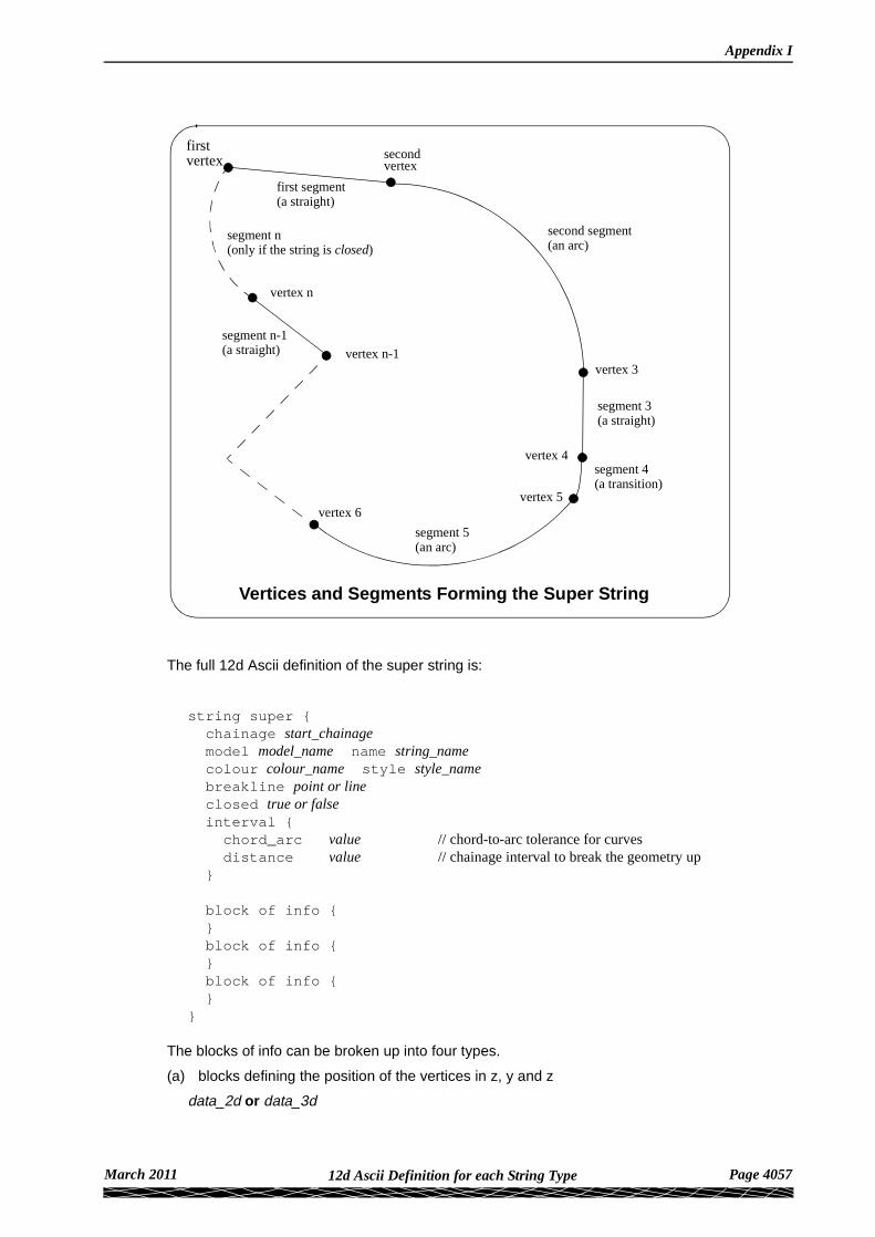
The full 12d Ascii definition of the super string is:
string super {chainage start_chainagemodel model_name name string_namecolour colour_name style style_namebreakline point or lineclosed true or falseinterval {
chord_arc value // chord-to-arc tolerance for curvesdistance value // chainage interval to break the geometry up
}
block of info { }block of info { }block of info { }
}
The blocks of info can be broken up into four types.
(a) blocks defining the position of the vertices in z, y and z
data_2d or data_3d
Vertices and Segments Forming the Super String
firstsecond
vertex 3
vertex 4
vertex 5vertex 6
vertex n-1
vertex n
vertex
first segment(a straight)
second segment(an arc)
segment 3(a straight)
segment 4(a transition)
segment 5(an arc)
segment n-1(a straight)
vertex
segment n(only if the string is closed)
March 2011 Page 405712d Ascii Definition for each String Type

12d Model Reference Manual
(b) blocks defining the geometry of the segments
radius_data and major_data or geometry_data
(c) a superseded block defining vertices and segment geometry
data
(d) extra information for the vertices and/or segments
pipe diameters - diameter_value or diameter_dataculvert dimensions - culvert_value or culvert_datapipe/culvert justification - justifycolour - colour or colour_datavertex ids (point numbers) at each vertex- point_datatinability - breakline or vertex_tinability_data and segment_tinability_datavisibility - vertex_visible_data and segment_visible_datavertex text and annotation - vertex_text_data and vertex_annotation_datasegment text and annotation - segment_text_data and segment_annotation_datasymbols at vertices - symbol_value or symbol_datavertex attributes - vertex_attribute_datasegment attributes - segment_attribute_dataextrudesimage dataholes
The definition for the blocks of each type now follows.
(a) Blocks Defining the Position of the Vertices
For (x, y) Values with a Constant z
If there is only (x,y) values at each vertex (like a 2d string):
data_2d { // keyword x-value y-value " " " "}
and if there is a non-null constant z for the string
z value
For (x,y,z) Values
If there is (x,y,z) values at each vertex (like a 3d string):
data_3d { // keyword x-value y-value z-value " " " " " "}
(b) Blocks Defining the Geometry of the Segments
Straights and Arcs Only for the Segments
If data_2d or data_3d was used, it is possible to add radius and bulge_flag data:
radius_data { // keyword radius for first segment radius for second segment
Page 4058 March 201112d Ascii Definition for each String Type

Appendix I
... radius for last segment
}
major_data { // keyword bulge flag for first segment bulge flag for second segment ... bulge flag for last segment
}
Straights, Arcs and Transitions (Spiral and non-Spiral Transitions) for the Segments
If data_2d or data_3d was used, it is possible to specify if the segments are straight, arcs or transitions using a geometry_data block.
geometry_data {segment_info_1 {
information on the first segment}segment_info_2 {
information on the second segment}
" "" "
segment_info_n-1 { // the last segment if it is openinformation on the (n-1) segment
}segment_info_n { // the last segment if it is closed
information on the n-th segment}
}
where the segment_info blocks are from the following:
(a) Straight
No parameters are needed for defining a straight segment. The straight block is simply:
straight { // no parameters are needed for a straight}
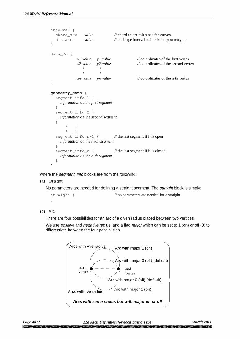
(b) Arc
There are four possibilities for an arc of a given radius placed between two vertices.
We use positive and negative radius, and a flag major which can be set to 1 (on) or off (0) to differentiate between the four possibilities.
March 2011 Page 405912d Ascii Definition for each String Type

12d Model Reference Manual
So the arc block is:
arc {radius value // radius of the arc (+ve is above the line connecting the vertices)major 0 or 1 // 0 is the smaller arc, 1 the larger arc).
}
(c) Spiral - this covers both spiral and non-spiral transitions
There can be a partial transition between adjacent vertices. The partial transition is defined by the parameters
l1 length of the full transition up to the start vertexr1 radius of the transition at the start vertexa1 angle in decimal degrees of the tangent to the transition at the start vertexl2 length of the full transition up to the end vertexr2 radius at the end vertexa2 angle in decimal degrees of the tangent to the transition at the end vertex
Since a radius can not be zero, a radius of infinity is denoted by zero.
The transition is said to be a leading transition if the absolute value of the radius is increasing along the direction of the transition (the transition will tighten). Otherwise it is a trailing transition.
If a leading transition is a full transition then r1 = 0 and l1 = 0. Similarly if a trailing transition is a full transition then r2 = 0 and l2 = 0.
For a partial transition, if the coordinates of the start of the full transition are needed then they can be calculated from l1,r1,a1, l2,r2,a2 and the co-ordinates of the start and end vertices.
Note that the radii can be positive or negative. If the radii’s are positive then a leading transition will curl to the right (and will be above the line joining the start and end vertices).
Arc with major 1 (on)
Arc with major 0 (off) (default)
Arcs with same radius but with major on or off
startvertex
endvertex
Arc with major 1 (on)
Arc with major 0 (off) (default)
Arcs with +ve radius
Arcs with -ve radius
Page 4060 March 201112d Ascii Definition for each String Type

Appendix I
The parameters for the spiral block are:
spiral {type value // type can be clothoid, cubic parabola, westrail-cubic,
// cubic spiral, natural clothoid, bloss, // bloss, sinusoidal, cosinusoidal
leading 1 or 0 // 1 denotes a leading transition, 0 a trailing transitionl1 value // length of the full transition at start vertexr1 value // radius at the start vertexa1 value // angle in decimal degrees of the tangent to the transition
// at the start vertexl2 value // length of the full transition at end vertexr2 value // radius at end vertexa2 value // angle in decimal degrees of the tangent to the transition
// at the end vertex}
Notes
1. The spiral block covers both spiral and non-spiral transitions.
2. The transitions/spirals supported by 12d Model are:
Clothoid - spiral approximation used by Australian road authorities and Queensland Rail.
Cubic parabola – special transition curve used by NSW railways. Not a spiral.
Westrail cubic – spiral approximating used by WA railways.
Cubic spiral – low level spiral approximation. Only ever used in surveying textbooks.
Natural Clothoid – the proper Euler spiral. Not used by any authority.
Bloss – special transition used by Deutsche Bahn. Not a spiral.
Sinusoidal - special transition. Not a spiral.
l2 - l1 = the length of transitionfrom the start vertex tothe end vertex
startvertex
endvertex
partial transition segment betweenthe super alignment vertices
Example of a Leading Partial Transition with Positive Radiii.e. radius increases along the transition
start of full transition( radius of "infinity"but will be denotedas a radius of 0)
l1 = length of thefull transition beforethe start vertex
r1 = radius atstart vertex
r2 = radius atend vertex
l2 = length of thefull transition up toend vertex
a2 = angle of the tangentto the transition at end vertex
a1 = angle of the tangentto the transition at start vertex
March 2011 Page 406112d Ascii Definition for each String Type

12d Model Reference Manual
Cosinusoidal - special transition. Not a spiral.
(c) Block Defining the Vertices and SegmentsFor compatibility with the polyline, the data block gives the (x,y,z,radius,bulge) values at each vertex of the string and so defines both the vertices and the geometry of the segments in the one block.
data { // keyword x-value y-value z-value radius bulge " " " " " "}
(d) Other Blocks
Pipe Diameters
There can be one pipe diameter value for the entire super string or the pipe diameter varies for each segment of the super string.
diameter_value valueor
diameter_data { // keyword pipe diameter for first segment pipe diameter for second segment ... pipe diameter for last segment}
Culvert Dimensions
There can be one culvert width and height for the entire super string or the culvert width and height vary for each segment of the super string.
culvert_value {width valueheight value
}or
culvert_data { properties {width value // width and height for first segment height value } properties {width value // width and height for second segment height value }
... properties {width value // width and height for last segment height value }}
Justification for Pipe or Culverts
There can be only one justification for the pipe or culvert for the entire super string.
justify justification // bottom or invert// top or obvert
Page 4062 March 201112d Ascii Definition for each String Type
Appendix I
// centre (default)
Colour
There can be one colour for the entire super string which is given by the colour command at the beginning of the string definitions (before the blocks of information) or the colour varies for each segment of the super string and is specified in a colour_data block.
colour_data { // keyword colour for first segment colour for second segment ... colour for last segment
}
Vertex Id’s (Point Numbers)
Each vertex can have a vertex id (point number). This is not the order number of the vertex in the string but is a separate id which is usually different for every vertex in every string. The vertex id can be alphanumeric.
point_data { // keyword vertex id or first vertex // alphanumeric vertex id for second vertex ... vertex id for last vertex
}
Tinability
For a super string, the concept of breakline has been extended to a property called tinable which can be set independently for each vertex and each segment of the super string.
If a vertex is tinable, then the vertex is used in triangulations. If the vertex is not tinable, then the vertex is ignored when triangulating.
If a segment is tinable, then the segment is used as a side of a triangle during triangulation. This may not be possible if there are crossing tinable segments.
vertex_tinable_data { // keyword tinable flag for first vertex // 1 for tinable tinable flag for second vertex // 0 for not tinable ... tinable flag for last vertex
segment_tinable_data { // keyword tinable flag for first segment // 1 for tinable tinable flag for second segment // 0 for not tinable ... tinable flag for last segment
}Note that even if a segment is set to tinable, is can only be used if both its end vertices are also tinable.
Visibility
For a super string, the concept of visibility and invisibility for vertices and segments has been introduced.
March 2011 Page 406312d Ascii Definition for each String Type

12d Model Reference Manual
vertex_visible_data { // keyword visibility flag for first vertex // 1 for visible visibility flag for second vertex // 0 for invisible ... visibility flag for last vertex}
segment_visible_data { // keyword visibility flag for first segment // 1 for visible visibility flag for second segment // 0 for invisible ... visibility flag for last segment}
Vertex Text and Vertex Annotation
There can be the same piece of text for every vertex in the super string or a different text for each vertex of the super string. How the text is drawn is specified by vertex annotation values. Note that in vertex annotations, all vertices must be either worldsize or all vertices papersize. That is, worldsize and papersize can not be mixed - the first one found is used for all vertices.
vertex_text_value textor
vertex_text_data { // keyword text for first vertex // text string, enclose text for second vertex // by "" if there are any ... // spaces in the text string text for last vertex}
vertex_annotate_value { // keyword angle value offset value raise value textstyle textstyle_name slant degrees xfactor value
worldsize value or papersize value or screensize value justify "top|middle|bottom-left|centre|right"
colour colour_name}
or
vertex_annotate_data { // keyword properties { angle value offset value raise value textstyle textstyle slant degrees xfactor value
worldsize value or papersize value or screensize value justify "top|middle|bottom-left|centre|right"
colour colour_name } properties { text properties second vertex }
properties { ... } properties { text properties for last vertex }}
Segment Text and Segment Annotation
There can be the same piece of text for every segment in the super string or a different text for each segment of the super string. How the text is drawn is specified by segment annotation
Page 4064 March 201112d Ascii Definition for each String Type

Appendix I
values. Note that in segment annotations, all segments must be either worldsize or all segments papersize. That is, worldsize and papersize can not be mixed - the first one found is used for all segments. However, vertex text and segment text do not both have to be papersize or worldsize.
segment_text_value textor
segment_text_data { // keyword text for first segment // text string, enclose text for second segment // by "" if there are any ... // spaces in the text string text for last segment
}
segment_annotate_value { // keyword angle value offset value raise value textstyle textstyle slant degrees xfactor value
worldsize value or papersize value or screensize value justify "top|middle|bottom-left|centre|right"
colour colour_name}
or
segment_annotate_data { // keyword properties { angle value offset value raise value textstyle textstyle slant degrees xfactor value
worldsize value or papersize value or screensize value justify "top|middle|bottom-left|centre|right"
colour colour_name } properties { text properties second segment
} properties { ...
} properties { text properties for last segment }
}
Symbols
There can be the same symbol (defined as a linestyle) for every vertex in the super string or a different symbol for each vertex of the super string. If a symbol does not have a colour, then it uses the string colour or the segment colour.
symbol_value { // keyword style linestyle_name colour colour_name size value rotation value // in dms
offset value raise value}
or
symbol_data { // keyword properties { style linestyle_name colour colour_name size value style linestyle colour colour size value rotation value // in dms
offset value raise value } properties { symbol and properties for second vertex } properties { ...
March 2011 Page 406512d Ascii Definition for each String Type

12d Model Reference Manual
} properties { symbol and properties for last vertex }}
Vertex Attributes
Each vertex can have one or more user defined named attributes.
vertex_attribute_data { // key word attributes { attribute_type attribute_name attribute_value attribute_type attribute_name attribute_value ...
attribute_type attribute_name attribute_value } attributes { named attributes for second vertex } attributes { ... } attributes { named attributes for last vertex }}
Segment Attributes
Each segment can have one or more user defined named attributes.
segment_attribute_data { // keyword attributes { attribute_type attribute_name attribute_value
attribute_type attribute_name attribute_value ...
attribute_type attribute_name attribute_value } attributes { named attributes for second segment } attributes { ... } attributes { named attributes for last segment } }
Page 4066 March 201112d Ascii Definition for each String Type

Appendix I
Super Alignment StringIn an alignment string, only the intersection point method (IP’s) could be used to construct the horizontal and vertical geometry. The IP definition is actually a constructive definition and the tangents points and segments between the tangent points (lines, arcs, transitions etc.) are calculated from the IP definition. For an alignment string, only the IP definitions are included in the 12d ascii file.
For a super alignment, the horizontal and vertical geometry are also defined separately and with construction definitions but the construction definition can be much more complex than just IP’s. For example, an arc could be defined as being tangential to two offset elements, or constrained to go through a given point.
If the horizontal construction methods are consistent then the horizontal geometry can be solved, and the horizontal geometry expressed in terms of consecutive segments (lines, arcs, transitions) that are easily understood and drawn.
Similarly if the vertical construction methods are consistent then the vertical geometry can be solved, and the vertical geometry expressed in terms of consecutive segments (lines, arcs, parabolas) that are easily understood and drawn.
Unlike the alignment, the super alignment stores both the construction methods (the parts) and the resulting vertices and segments (lines, arcs, transitions etc.) that make up the horizontal and vertical geometry (the data).
For many applications such as uploading to survey data collectors or machine control devices, only the horizontal data and the vertical data are required, not the construction methods (i.e. the horizontal and vertical parts). When reading the 12d Ascii of a super alignment, only the horizontal and vertical data needs to be read in and the constructive methods (the horizontal and vertical parts) can be skipped over.
Vertices and Segments Forming the Horizontal Data for a Super Alignment
firstsecond
vertex 3
vertex 4
vertex 5vertex 6
vertex n-1
vertex n
vertex
first segment(a straight)
second segment(an arc)
segment 3(a straight)
segment 4(a transition)
segment 5(an arc)
segment n-1(a straight)
vertex
segment n(only if the string is closed)
March 2011 Page 406712d Ascii Definition for each String Type

12d Model Reference Manual
Notes
1. Just using the horizontal and vertical data is valid as long as the super alignment geometry is consistent (and solves) and the horizontal and vertical parts can be created.
There are flags in the 12d Ascii of the super alignment to say that the horizontal and vertical geometry is consistent and solves.
2. Segments meeting at a common vertex do not have to be tangential although for most road and rail applications, they should be.
The full 12d Ascii definition of the super alignment is:
string super_alignment {//name string_namechainage start_chainagecolour colour_namestyle style_namebreakline point or lineclosed true or falsespiral_type transition_type // the spiral_types are clothoid,
// cubic parabola, westrail-cubic, cubic spiral,// natural clothoid, bloss, sinusoidal and // cosinusoidal. Note that some spiral_type’s// are non-spiral transitions
valid_horizontal true or false // if true then the horizontal geometry// is consistent and solves
valid_vertical true or false // if true then the horizontal geometry// is consistent and solves
block of info { }
block of info { }
block of info { }
} // end of super alignment
where the block of info can be one of more of:
attributes, horizontal_parts, horizontal_data, vertical_parts, vertical_data.
The attributes block has been described in the earlier section “Attributes” .
The structure of the blocks horizontal_parts, horizontal_data which define the horizontal geometry, and vertical_parts and vertical_data which define the vertical geometry will now be described in more detail.
For information on horizontal geometry, go to “Horizontal Geometry” vertical geometry “Vertical Geometry”
Page 4068 March 201112d Ascii Definition for each String Type

Appendix I
Horizontal GeometryThe horizontal geometry is described by two blocks - the horizontal_parts block and the horizontal_data block.
The horizontal_parts block contains the methods to construct the horizontal geometry such as float (fillet) an arc of a certain radius between two given lines or create a transition (spiral or non-spiral transition) between a line and an arc.
If the horizontal construction methods are consistent, then they can be solved to form a string made up of lines, arcs and transitions. The horizontal_data block is simply a list of the vertices and segments (lines, arcs etc.) that make up the solved geometry.
If the geometry in the horizontal_parts can be solved and produces a valid horizontal_data block, then the flag valid_horizontal in the super_alignment block is set to true.
valid_horizontal true or false //true if the horizontal geometry can be solved and// hence create a valid horizontal_data
horizontal_parts {/ / methods for creating the horizontal geometry....
}
horizontal_data { // the horizontal segments that make up the solved geometry....
}
For information on horizontal_parts, go to the section “Horizontal_parts” horizontal_data “Horizontal_data”
Horizontal_parts
The horizontal_parts block describes the methods used to construct the horizontal geometry of the super alignment. The parts that make up the horizontal geometry are defined in chainage order from the start to the end of the super alignment.
horizontal_parts { // methods for creating the horizontal geometryblocks defining the sequential partsmaking up the horizontal geometry
}
Apart from the special case of parts defined by horizontal intersection points and their accompanying transitions and arcs, the other parts in the horizontal_parts block are not documented.
Horizontal_parts for defined by IP Method Only
For a horizontal intersection point (HIP) with no transitions or arc defined at that HIP, the part is defined by:
ip {id value // part id - a number that is unique for each horizontal and vertical part,
// and the value of part id is a multiple of 100x value // x co-ordinate of the horizontal intersection pointy value // y co-ordinate of the horizontal intersection point
}
For a horizontal intersection point (HIP) with an arc but no transitions defined at that HIP, the part is defined by
arc {id value // part id - a number that is unique for each horizontal and vertical part,
// and the value of part id is a multiple of 100
March 2011 Page 406912d Ascii Definition for each String Type

12d Model Reference Manual
r value // radius of the arc at the HIPx value // x co-ordinate of the HIPy value // y co-ordinate of the HIP
}
For a horizontal intersection point (HIP) with an arc and transitions defined at that HIP, the part is defined by
spiral {id value // part id - a number that is unique for each horizontal and vertical part,
// and the value of part id is a multiple of 100r value // radius of the arc at the HIPl1 value // length of the leading transition at the HIPl2 value // length of the trailing transition at the HIPx value // x co-ordinate of the HIPy value // y co-ordinate of the HIP
}
Note that the transition used in the spiral block is given by spiral_type in the super_alignment block.
Hence a super alignment with horizontal geometry defined by IP methods only would consist of a horizontal_parts section with only the above ip, arc and spiral blocks in it.
horizontal_parts {
ip_spiral_arc {values // values defining the ip_spiral_arc block"values
}....
ip_spiral_arc {values // values defining the ip_spiral_arc block"values
}
For example,
Page 4070 March 201112d Ascii Definition for each String Type

Appendix I
Horizontal_data
The horizontal_data block contains the solved horizontal geometry of the super alignment.
The solved horizontal geometry is made up of a series of (x,y) vertices given in a data_2d block followed by a geometry_data block specifying the geometry of the segments between adjacent vertices. The segment can be a straight line, an arc, a transition (e.g. a spiral) or a partial transition.
If the horizontal geometry has n vertices, then there will be (n-1) segments for an open super alignment or n segments if the super alignment is closed.
The format of the horizontal_data block is:
horizontal_data {name ""chainage valuebreakline line or pointcolour colourstyle linestyleclosed 0 or 1 // 0 if the string is open, 1 if it is closed
HIP with arc andleading and trailingtransitions
horizontal_parts { ip {
id 100 x 42606.66161172 y 37239.28824481 }
ip { id 200 x 43134.36832349 y 37330.26705997 }
spiral { id 300 r 50 l1 30 l2 40 x 43336.6595 y 37469.2563}
arc { id 400 r 75 x 43481.15324268 y 37331.6431906}
ip { id 500
x 43627.02308964 y 37544.94343852 }}
1st HIPHIP only
2nd HIPHIP only
3rd HIP
4th HIPHIP with arc only
5th HIPHIP only
Horizontal Parts with IP Methods Only
Plan View of Super Alignment
Super Alignment Being Edited
Unique Part idincrementing by 100
March 2011 Page 407112d Ascii Definition for each String Type
12d Model Reference Manual
interval {chord_arc value // chord-to-arc tolerance for curvesdistance value // chainage interval to break the geometry up
}
data_2d { x1-value y1-value // co-ordinates of the first vertex x2-value y2-value // co-ordinates of the second vertex " " " " xn-value yn-value // co-ordinates of the n-th vertex}
geometry_data {segment_info_1 {
information on the first segment}segment_info_2 {
information on the second segment}
" "" "
segment_info_n-1 { // the last segment if it is openinformation on the (n-1) segment
}segment_info_n { // the last segment if it is closed
information on the n-th segment}
}
where the segment_info blocks are from the following:
(a) Straight
No parameters are needed for defining a straight segment. The straight block is simply:
straight { // no parameters are needed for a straight}
(b) Arc
There are four possibilities for an arc of a given radius placed between two vertices.
We use positive and negative radius, and a flag major which can be set to 1 (on) or off (0) to differentiate between the four possibilities.
Arc with major 1 (on)
Arc with major 0 (off) (default)
Arcs with same radius but with major on or off
startvertex
endvertex
Arc with major 1 (on)
Arc with major 0 (off) (default)
Arcs with +ve radius
Arcs with -ve radius
Page 4072 March 201112d Ascii Definition for each String Type

Appendix I
So the arc block is:
arc {radius value // radius of the arc (+ve is above the line connecting the vertices)major 0 or 1 // 0 is the smaller arc, 1 the larger arc).
}
(c) Spiral - this covers both spiral and non-spiral transitions
There can be a partial transition between adjacent vertices. The partial transition is defined by the parameters
l1 length of the full transition up to the start vertexr1 radius of the transition at the start vertexa1 angle in decimal degrees of the tangent to the transition at the start vertexl2 length of the full transition up to the end vertexr2 radius at the end vertexa2 angle in decimal degrees of the tangent to the transition at the end vertex
Since a radius can not be zero, a radius of infinity is denoted by zero.
The transition is said to be a leading transition if the absolute value of the radius is increasing along the direction of the transition (the transition will tighten). Otherwise it is a trailing transition.
If a leading transition is a full transition then r1 = 0 and l1 = 0. Similarly if a trailing transition is a full transition then r2 = 0 and l2 = 0.
For a partial transition, if the coordinates of the start of the full transition are needed then they can be calculated from l1,r1,a1, l2,r2,a2 and the co-ordinates of the start and end vertices.
Note that the radii can be positive or negative. If the radii’s are positive then a leading transition will curl to the right (and will be above the line joining the start and end vertices).
The parameters for the spiral block are:
spiral {type transition_type // any of the transitions supported in 12dleading 1 or 0 // 1 denotes a leading transition, 0 a trailing transitionl1 value // length of the full transition at start vertexr1 value // radius at the start vertexa1 value // angle in decimal degrees of the tangent to the transition
// at the start vertexl2 value // length of the full transition at end vertex
l2 - l1 = the length of transitionfrom the start vertex tothe end vertex
startvertex
endvertex
partial transition segment betweenthe super alignment vertices
Example of a Leading Partial Transition with Positive Radiii.e. radius increases along the transition
start of full transition( radius of "infinity"but will be denotedas a radius of 0)
l1 = length of thefull transition beforethe start vertex
r1 = radius atstart vertex
r2 = radius atend vertex
l2 = length of thefull transition up toend vertex
a2 = angle of the tangentto the transition at end vertex
a1 = angle of the tangentto the transition at start vertex
March 2011 Page 407312d Ascii Definition for each String Type

12d Model Reference Manual
r2 value // radius at end vertexa2 value // angle in decimal degrees of the tangent to the transition
// at the end vertex}
Notes
1. The spiral block covers both spiral and non-spiral transitions.
2. The transitions/spirals supported by 12d Model are:
Clothoid - spiral approximation used by Australian road authorities and Queensland Rail.
Cubic parabola – special transition curve used by NSW railways. Not a spiral.
Westrail cubic – spiral approximating used by WA railways.
Cubic spiral – low level spiral approximation. Only ever used in surveying textbooks.
Natural Clothoid – the proper Euler spiral. Not used by any authority.
Bloss – special transition used by Deutsche Bahn. Not a spiral.
Sinusoidal - special transition. Not a spiral.
Cosinusoidal - special transition. Not a spiral.
Page 4074 March 201112d Ascii Definition for each String Type

Appendix I
Vertical GeometryThe vertical geometry is described by two blocks - the vertical_parts block and the vertical_data block.
The vertical_parts block contains the methods to construct the vertical geometry such as float (fit) a parabola of a certain length between two given lines.
If the vertical construction methods are consistent, then they can be solved to form a string made up of lines, parabolas and arcs. The vertical_data block is simply a list of the vertices and segments (lines, parabolas and arcs) that make up the solved geometry.
If the geometry in the vertical_parts can be solved and produces a valid vertical_data block, then the flag valid_vertical in the super_alignment block is set to true.
valid_vertical true or false///true if the vertical geometry can be solved and// hence create a valid vertical_data
vertical_parts { // methods for creating the vertical geometry....
}
vertical_data { // the vertical geometry....
}
For information on vertical_parts, go to the section “Vertical_parts” vertical_data “Vertical_data”
Vertical_parts
The vertical_parts block describes the methods used to construct the vertical geometry of the super alignment. The parts that make up the vertical geometry are defined in chainage order from the start to the end of the super alignment.
vertical_parts { // methods for creating the vertical geometryblocks defining the sequential partsmaking up the vertical geometry
}
Apart from the special case of parts defined by vertical intersection points and their accompanying parabolas and arcs, the other parts in the vertical_parts block are undocumented.
Vertical_parts for defined by IP Method Only
For a vertical intersection point (VIP) with no parabola or arc defined at that VIP, the part is defined by:
ip {id value // part id - a number that is unique for each horizontal and vertical part,
// and the value of part id is a multiple of 100x value // chainage co-ordinate of the VIPy value // height co-ordinate of the VIP
}
For a vertical intersection point (VIP) with a parabola defined by a k value at that VIP, the part is defined by
kvalue {id value // part id - a number that is unique for each horizontal and vertical part,
// and the value of part id is a multiple of 100k value // k-value of the parabola at the VIP
March 2011 Page 407512d Ascii Definition for each String Type

12d Model Reference Manual
x value // chainage co-ordinate of the VIPy value // height co-ordinate of the VIP
}
For a vertical intersection point (VIP) with a parabola defined by length at that VIP, the part is defined by
length {id value // part id - a number that is unique for each horizontal and vertical part,
// and the value of part id is a multiple of 100l value // length of the parabola at the VIPx value // chainage co-ordinate of the VIPy value // height co-ordinate of the VIP
}
For a vertical intersection point (VIP) with a parabola defined by an effective radius at that VIP, the part is defined by
radius {id value // part id - a number that is unique for each horizontal and vertical part,
// and the value of part id is a multiple of 100r value // effective radius of the parabola at the VIPx value // chainage co-ordinate of the VIPy value // height co-ordinate of the VIP
}
For a vertical intersection point (VIP) with an asymmetric parabola defined by the start and end lengths at that VIP, the part is defined by
length {id value // part id - a number that is unique for each horizontal and vertical part,
// and the value of part id is a multiple of 100l1 value // start length of the asymmetric parabola at the VIPl2 value // end length of the asymmetric parabola at the VIPx value // chainage co-ordinate of the VIPy value // height co-ordinate of the VIP
}
For a vertical intersection point (VIP) with an arc defined by a radius at that VIP, the part is defined by
arc {id value // part id - a number that is unique for each horizontal and vertical part,
// and the value of part id is a multiple of 100r value // radius of the arc at the VIPx value // chainage co-ordinate of the VIPy value // height co-ordinate of the VIP
}
Hence a super alignment with vertical geometry defined by IP methods only would consist of a vertical_parts section with only the above ip, parabola and arc blocks in it.
vertical_parts {
ip_parabola_arc {values // values defining the ip_parabola_arc block"
Page 4076 March 201112d Ascii Definition for each String Type

Appendix I
values}
....ip_parabola_arc {
values // values defining the ip_parabola_arc block"values
}}
For example,
vertical_parts {ip {
id 600 x -50.8459652 y 159.79764161
}kvalue {
id 700 k 1.25 x 38.4627 y 179.2126
}length {
id 800 l 50 x 172.61694837 y 154.72967932
}asymmetric {
id 900 l1 25 l2 75 x 270.0182 y 208.1493
}arc {
id 1000 r 1000 x 424.2402 y 196.5637
}radius {
id 1100 r 200 x 526.7263 y 201.5302
} ip {
id 1200 x 637.69216273 y 198.71894484
}}
1st VIPVIP only
2nd VIPParabola defined
5th VIPArc with radius
Vertical Parts with IP Methods Only
Section View of Super Alignment
Vertical Geometry Being Edited
by k value
3rd VIPParabola definedby length
4th VIPAsymmetric parabola definedby two lengths
7th VIPVIP only
6th VIPParabola definedby effective radius
Unique Part idincrementing by 100
March 2011 Page 407712d Ascii Definition for each String Type

12d Model Reference Manual
Vertical_data
The vertical_data block contains the solved vertical geometry of the super alignment.
The solved vertical geometry is made up of a series of (chainage,height) vertices given in a data_2d block followed by a geometry_data block specifying the geometry of the segments between adjacent vertices. The segment can be a straight line, a parabola or an arc.
If the vertical geometry has n vertices, then there will be (n-1) segments for an open super alignment or n segments if the super alignment is closed.
The format of the vertical_data block is:
vertical_data {name ""chainage valuebreakline line or pointcolour colourstyle linestyleclosed 0 or 1 // 0 if the string is open, 1 if it is closedinterval {
chord_arc value // chord-to-arc tolerance for curvesdistance value // chainage interval to break the geometry up
}
data_2d { ch1-value ht1-value // co-ordinates of the first vertex ch2-value ht2-value // co-ordinates of the second vertex " " " " chn-value htn-value // co-ordinates of the n-th vertex}
geometry_data {segment_info_1 {
information on the first segment}segment_info_2 {
information on the second segment}
" "" "
segment_info_n-1 { // the last segment if it is openinformation on the (n-1) segment
}segment_info_n { // the last segment if it is closed
information on the n-th segment}
}
where the segment_info blocks are from the following:
(a) Straight
No parameters are needed for defining a straight segment. The straight block is simply:
straight { // no parameters are needed for a straight}
(b) Arc
Since vertical geometry can’t go backwards in chainage value, the majors arcs can not be used and hence there are only possibilities for an arc of a given radius placed between two
Page 4078 March 201112d Ascii Definition for each String Type

Appendix I
vertices.
We use positive and negative radius to differentiate between the four possibilities.
So the arc block is:
arc {radius value // radius of the arc (+ve is above the line connecting vertices)major value // this is ignored since only minor arcs are used
}
(c) Parabola
There can be a parabola between adjacent vertices. The parabola is defined by giving the co-ordinates of the vertical intersection point for the parabola
chainage chainage of the VIP of the parabolaheight height of the VIP of the parabola
The parameters for the parabola block are:
parabola {chainage value // chainage of the VIP of the parabolaheight value // height of the VIP of the parabola
}
Please continue to the next section “12d Ascii Definition for Tins”
only arc with major 0 (off) is allowed
Arcs with same absolute radius
startvertex
endvertex
only the arc with major 0 (off) is allowe
Arc with +ve radius
Arc with -ve radius
(chainage,height)
startvertex
endvertex
Vertical intersection point given by
Example of a Parabola
March 2011 Page 407912d Ascii Definition for each String Type
12d Model Reference Manual
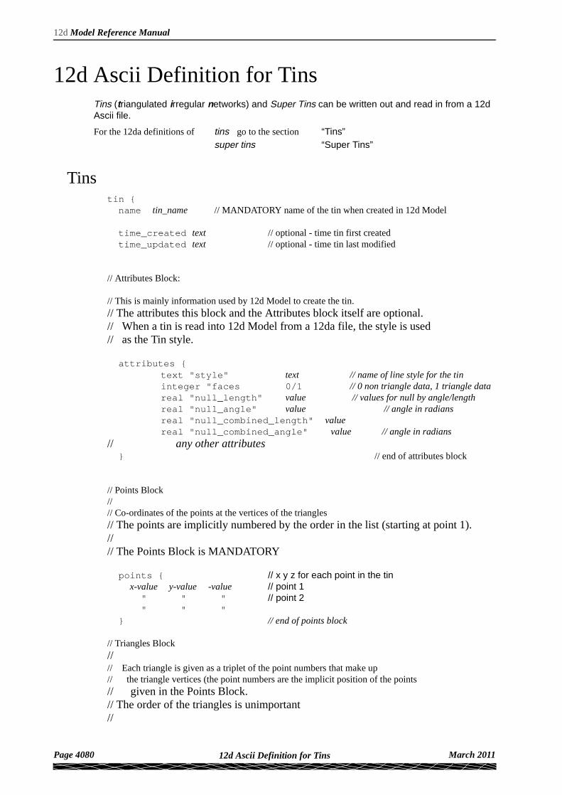
12d Ascii Definition for TinsTins (triangulated irregular networks) and Super Tins can be written out and read in from a 12d Ascii file.
For the 12da definitions of tins go to the section “Tins” super tins “Super Tins”
Tinstin {name tin_name // MANDATORY name of the tin when created in 12d Model
time_created text // optional - time tin first createdtime_updated text // optional - time tin last modified
// Attributes Block:
// This is mainly information used by 12d Model to create the tin.// The attributes this block and the Attributes block itself are optional.// When a tin is read into 12d Model from a 12da file, the style is used// as the Tin style.
attributes {text "style" text // name of line style for the tininteger "faces 0/1 // 0 non triangle data, 1 triangle datareal "null_length" value // values for null by angle/lengthreal "null_angle" value // angle in radiansreal "null_combined_length" valuereal "null_combined_angle" value // angle in radians
// any other attributes} // end of attributes block
// Points Block//// Co-ordinates of the points at the vertices of the triangles// The points are implicitly numbered by the order in the list (starting at point 1).//// The Points Block is MANDATORY
points { // x y z for each point in the tinx-value y-value -value // point 1
" " " // point 2 " " "} // end of points block
// Triangles Block//// Each triangle is given as a triplet of the point numbers that make up// the triangle vertices (the point numbers are the implicit position of the points// given in the Points Block.// The order of the triangles is unimportant//
Page 4080 March 201112d Ascii Definition for Tins
Appendix I
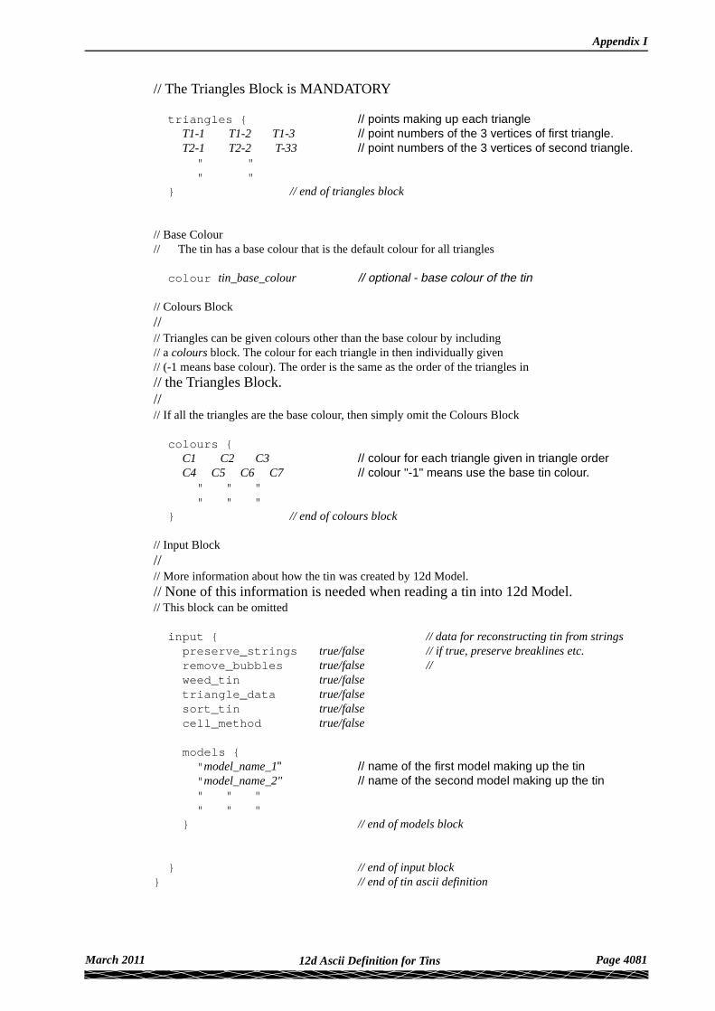
// The Triangles Block is MANDATORY
triangles { // points making up each triangle T1-1 T1-2 T1-3 // point numbers of the 3 vertices of first triangle. T2-1 T2-2 T-33 // point numbers of the 3 vertices of second triangle. " " " "
} // end of triangles block
// Base Colour// The tin has a base colour that is the default colour for all triangles
colour tin_base_colour // optional - base colour of the tin
// Colours Block//// Triangles can be given colours other than the base colour by including// a colours block. The colour for each triangle in then individually given// (-1 means base colour). The order is the same as the order of the triangles in // the Triangles Block.//// If all the triangles are the base colour, then simply omit the Colours Block
colours { C1 C2 C3 // colour for each triangle given in triangle order C4 C5 C6 C7 // colour "-1" means use the base tin colour. " " " " " "
} // end of colours block
// Input Block//// More information about how the tin was created by 12d Model.// None of this information is needed when reading a tin into 12d Model.// This block can be omitted
input { // data for reconstructing tin from stringspreserve_strings true/false // if true, preserve breaklines etc.remove_bubbles true/false // weed_tin true/falsetriangle_data true/falsesort_tin true/falsecell_method true/false
models {"model_name_1" // name of the first model making up the tin"model_name_2" // name of the second model making up the tin" " "" " "
} // end of models block
} // end of input block} // end of tin ascii definition
March 2011 Page 408112d Ascii Definition for Tins

12d Model Reference Manual
Super Tinssuper_tin {name tin_name // MANDATORY name of the super tin
time_created text // optional - time super tin first createdtime_updated text // optional - time super tin last modified
// Attributes Block:
// This is mainly information used by 12d Model to create the super tin.// The attributes in this block and the Attributes block itself are optional.// When a super tin is read into 12d Model from a 12da file, the style is used// as the Super Tin style.
attributes {text "style" text // name of line style for the tin
// any other attributes} // end of attributes block
// Super Tin Colour// The super tin has a base colour
colour tin_base_colour // optional - base colour of the super tin
// Tins Block//// This is the list of tins that make up the super tin.// This block is MANDATORY
tins { // list of tins for the super tin"tin_name_1" // name of the first tin making up the super tin"tin_name_2" // name of the second tin making up the super tin" " "" " "
} // end of tins block
} // end of super tin ascii definition
Please continue to the next section “12d Ascii Definition for Plot Frames” .
Page 4082 March 201112d Ascii Definition for Tins
Appendix I
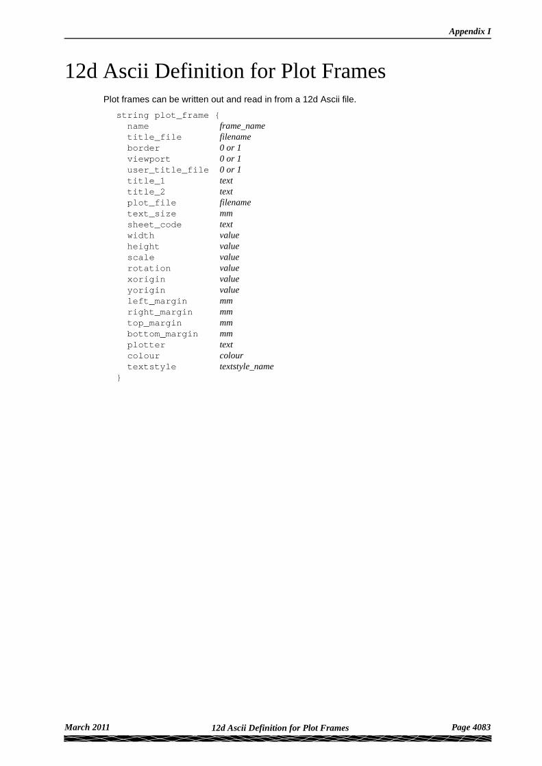
12d Ascii Definition for Plot FramesPlot frames can be written out and read in from a 12d Ascii file.
string plot_frame {name frame_nametitle_file filenameborder 0 or 1 viewport 0 or 1 user_title_file 0 or 1 title_1 texttitle_2 textplot_file filenametext_size mm sheet_code text width value height value scale value rotation value xorigin value yorigin value left_margin mm right_margin mm top_margin mm bottom_margin mm plotter text colour colour textstyle textstyle_name
}
March 2011 Page 408312d Ascii Definition for Plot Frames

12d Model Reference Manual
Page 4084 March 201112d Ascii Definition for Plot Frames