Hyundai HD78 Wabco ABS (Тормозная Система)
322
General Description .................................................... BR -3 Components ................................................. BR -14 Dignosis ........................................................ BR -16 On-Vehicle Inspection And Adjustment ....... BR -20 Specifications ............................................... BR -22 Vacuum Assisted Hydraulic Brake Brake Pedal Components ............................................ BR -27 Removal .................................................. BR -28 Installation ............................................... BR -28 Adjustment .............................................. BR -28 Brake Booster Component ............................................. BR -30 Removal .................................................. BR -31 Installation ............................................... BR -32 Inspection ................................................ BR -33 Brake Master Cylinder Components ............................................ BR -36 Removal .................................................. BR -37 Installation ............................................... BR -38 Load Sensing Proportioning Valve(LSPV) Components ............................................ BR -39 Removal .................................................. BR -40 Inspection ................................................ BR -40 Front Brake Assembly Disc Brake Components ............................................ BR -41 Removal .................................................. BR -42 Installation ............................................... BR -43 Disassembly ............................................ BR -44 Reassembly ............................................ BR -45 Inspection ................................................ BR -46 Drum Brake Components ............................................ BR -48 Removal .................................................. BR -49 Replacement ........................................... BR -50 Installation ............................................... BR -51 Parking Brake System Components ................................................. BR -52 Removal ....................................................... BR -53 Installation .................................................... BR -54 Adjustment .................................................... BR -56 Brake System (WABCO ABS) Rear Brake Assembly Drum Brake Components ............................................ BR -57 Removal .................................................. BR -58 Replacement ........................................... BR -59 Installation ............................................... BR -61 Exhaust Brake Component Location .............................. BR -62 Components ............................................ BR -63 Replacement ........................................... BR -67 Disassembly ............................................ BR -68 Reassembly ............................................ BR -68 Inspection ................................................ BR -70 ABS(Anti-Lock Brake System) Specifications ............................................... BR -72 Description .................................................... BR -72 Using Blink Code Diagnostics ..................... BR -76 DTC Troubleshooting ................................... BR -83 Repair Instruction ......................................... BR -88 Connector Configurations ............................ BR -90 Full Circuit Diagram ..................................... BR -91 Inspection ..................................................... BR -91 Adjustment .................................................... BR -92 ABS Modulator Removal .................................................. BR -94 Installation ............................................... BR -94 Wheel Speed Sensor Description .............................................. BR -95 Replacement ........................................... BR -95 ABS Control Module Removal .................................................. BR -97 Installation ............................................... BR -98 Schematic Diagrams .............................. BR -99 DTC Chart ............................................... BR -104 0000 ........................................................ BR -107 0001 ........................................................ BR -110 0002 ........................................................ BR -113 0003 ........................................................ BR -116 0004 ........................................................ BR -119 0009 ........................................................ BR -122 000A ........................................................ BR -125 000B ........................................................ BR -128 000C ........................................................ BR -131 000D ........................................................ BR -134 000E ........................................................ BR -137
-
Upload
bigfair-hd78 -
Category
Documents
-
view
731 -
download
20
description
Hyundai HD78 Wabco ABS (Тормозная Система)
Transcript of Hyundai HD78 Wabco ABS (Тормозная Система)
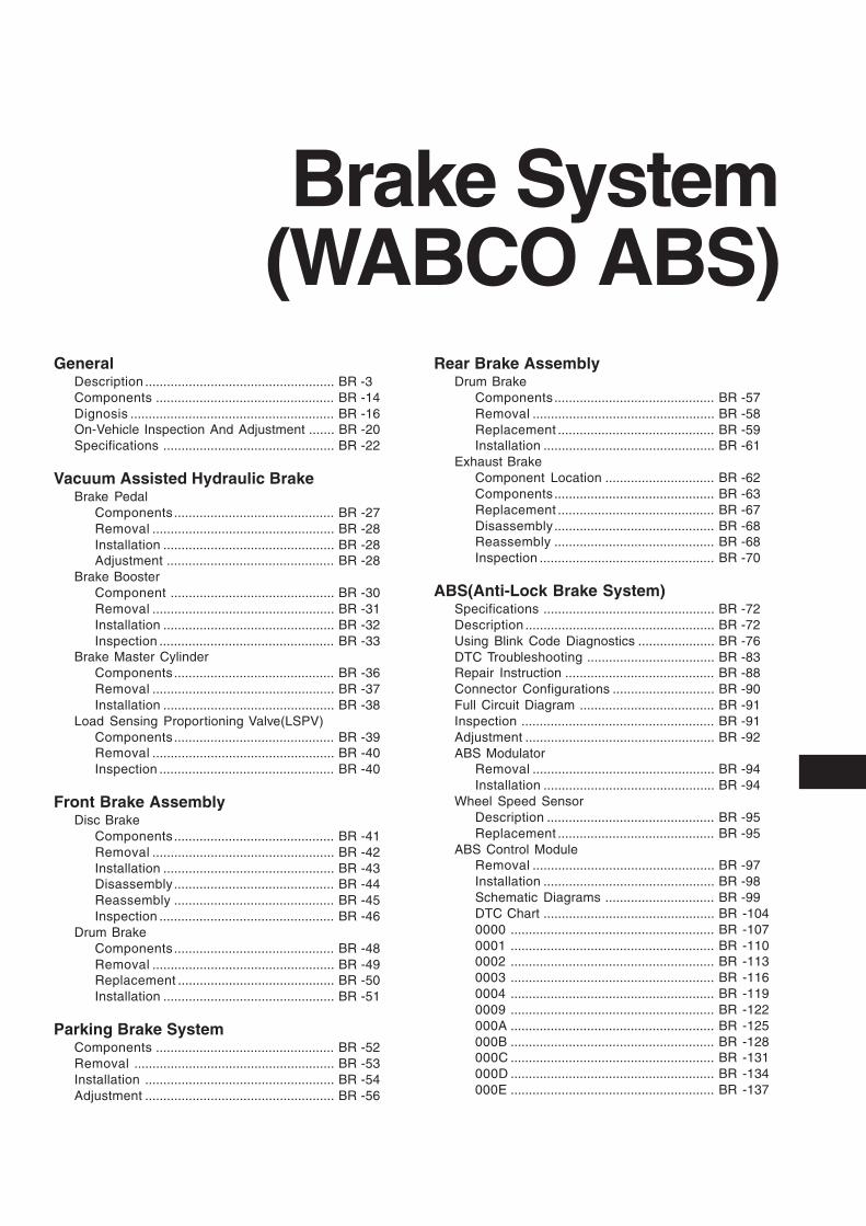
GeneralDescription .................................................... BR -3Components ................................................. BR -14Dignosis ........................................................ BR -16On-Vehicle Inspection And Adjustment ....... BR -20Specifications ............................................... BR -22
Vacuum Assisted Hydraulic BrakeBrake Pedal
Components............................................ BR -27Removal .................................................. BR -28Installation ............................................... BR -28Adjustment .............................................. BR -28
Brake BoosterComponent ............................................. BR -30Removal .................................................. BR -31Installation ............................................... BR -32Inspection ................................................ BR -33
Brake Master CylinderComponents............................................ BR -36Removal .................................................. BR -37Installation ............................................... BR -38
Load Sensing Proportioning Valve(LSPV)Components............................................ BR -39Removal .................................................. BR -40Inspection ................................................ BR -40
Front Brake AssemblyDisc Brake
Components............................................ BR -41Removal .................................................. BR -42Installation ............................................... BR -43Disassembly............................................ BR -44Reassembly ............................................ BR -45Inspection ................................................ BR -46
Drum BrakeComponents............................................ BR -48Removal .................................................. BR -49Replacement ........................................... BR -50Installation ............................................... BR -51
Parking Brake SystemComponents ................................................. BR -52Removal ....................................................... BR -53Installation .................................................... BR -54Adjustment .................................................... BR -56
Brake System(WABCO ABS)
Rear Brake AssemblyDrum Brake
Components............................................ BR -57Removal .................................................. BR -58Replacement ........................................... BR -59Installation ............................................... BR -61
Exhaust BrakeComponent Location .............................. BR -62Components............................................ BR -63Replacement ........................................... BR -67Disassembly............................................ BR -68Reassembly ............................................ BR -68Inspection ................................................ BR -70
ABS(Anti-Lock Brake System)Specifications ............................................... BR -72Description .................................................... BR -72Using Blink Code Diagnostics ..................... BR -76DTC Troubleshooting ................................... BR -83Repair Instruction ......................................... BR -88Connector Configurations ............................ BR -90Full Circuit Diagram ..................................... BR -91Inspection ..................................................... BR -91Adjustment .................................................... BR -92ABS Modulator
Removal .................................................. BR -94Installation ............................................... BR -94
Wheel Speed SensorDescription .............................................. BR -95Replacement ........................................... BR -95
ABS Control ModuleRemoval .................................................. BR -97Installation ............................................... BR -98Schematic Diagrams .............................. BR -99DTC Chart ............................................... BR -1040000 ........................................................ BR -1070001 ........................................................ BR -1100002 ........................................................ BR -1130003 ........................................................ BR -1160004 ........................................................ BR -1190009 ........................................................ BR -122000A ........................................................ BR -125000B ........................................................ BR -128000C ........................................................ BR -131000D ........................................................ BR -134000E ........................................................ BR -137
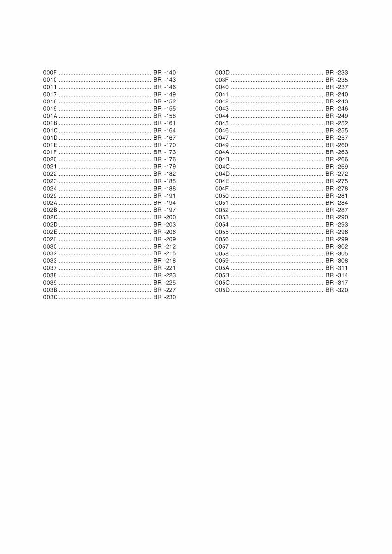
000F ........................................................ BR -1400010 ........................................................ BR -1430011 ........................................................ BR -1460017 ........................................................ BR -1490018 ........................................................ BR -1520019 ........................................................ BR -155001A ........................................................ BR -158001B ........................................................ BR -161001C ........................................................ BR -164001D ........................................................ BR -167001E ........................................................ BR -170001F ........................................................ BR -1730020 ........................................................ BR -1760021 ........................................................ BR -1790022 ........................................................ BR -1820023 ........................................................ BR -1850024 ........................................................ BR -1880029 ........................................................ BR -191002A ........................................................ BR -194002B ........................................................ BR -197002C ........................................................ BR -200002D ........................................................ BR -203002E ........................................................ BR -206002F ........................................................ BR -2090030 ........................................................ BR -2120032 ........................................................ BR -2150033 ........................................................ BR -2180037 ........................................................ BR -2210038 ........................................................ BR -2230039 ........................................................ BR -225003B ........................................................ BR -227003C ........................................................ BR -230
003D ........................................................ BR -233003F ........................................................ BR -2350040 ........................................................ BR -2370041 ........................................................ BR -2400042 ........................................................ BR -2430043 ........................................................ BR -2460044 ........................................................ BR -2490045 ........................................................ BR -2520046 ........................................................ BR -2550047 ........................................................ BR -2570049 ........................................................ BR -260004A ........................................................ BR -263004B ........................................................ BR -266004C ........................................................ BR -269004D ........................................................ BR -272004E ........................................................ BR -275004F ........................................................ BR -2780050 ........................................................ BR -2810051 ........................................................ BR -2840052 ........................................................ BR -2870053 ........................................................ BR -2900054 ........................................................ BR -2930055 ........................................................ BR -2960056 ........................................................ BR -2990057 ........................................................ BR -3020058 ........................................................ BR -3050059 ........................................................ BR -308005A ........................................................ BR -311005B ........................................................ BR -314005C ........................................................ BR -317005D ........................................................ BR -320
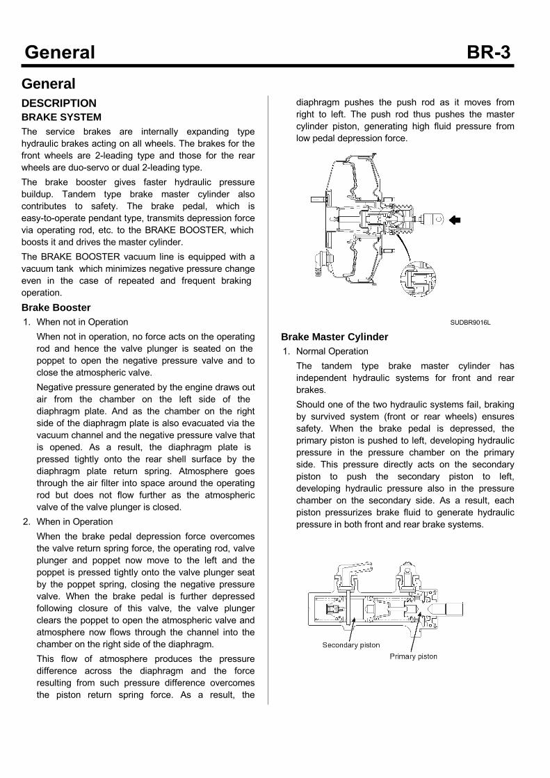
GeneralDESCRIPTIONBRAKE SYSTEMThe service brakes are internally expanding typehydraulic brakes acting on all wheels. The brakes for thefront wheels are 2-leading type and those for the rearwheels are duo-servo or dual 2-leading type.The brake booster gives faster hydraulic pressurebuildup. Tandem type brake master cylinder alsocontributes to safety. The brake pedal, which iseasy-to-operate pendant type, transmits depression forcevia operating rod, etc. to the BRAKE BOOSTER, whichboosts it and drives the master cylinder.The BRAKE BOOSTER vacuum line is equipped with avacuum tank which minimizes negative pressure changeeven in the case of repeated and frequent brakingoperation.Brake Booster1. When not in OperationWhen not in operation, no force acts on the operatingrod and hence the valve plunger is seated on thepoppet to open the negative pressure valve and toclose the atmospheric valve.Negative pressure generated by the engine draws outair from the chamber on the left side of thediaphragm plate. And as the chamber on the rightside of the diaphragm plate is also evacuated via thevacuum channel and the negative pressure valve thatis opened. As a result, the diaphragm plate ispressed tightly onto the rear shell surface by thediaphragm plate return spring. Atmosphere goesthrough the air filter into space around the operatingrod but does not flow further as the atmosphericvalve of the valve plunger is closed.
2. When in OperationWhen the brake pedal depression force overcomesthe valve return spring force, the operating rod, valveplunger and poppet now move to the left and thepoppet is pressed tightly onto the valve plunger seatby the poppet spring, closing the negative pressurevalve. When the brake pedal is further depressedfollowing closure of this valve, the valve plungerclears the poppet to open the atmospheric valve andatmosphere now flows through the channel into thechamber on the right side of the diaphragm.This flow of atmosphere produces the pressuredifference across the diaphragm and the forceresulting from such pressure difference overcomesthe piston return spring force. As a result, the
diaphragm pushes the push rod as it moves fromright to left. The push rod thus pushes the mastercylinder piston, generating high fluid pressure fromlow pedal depression force.
SUDBR9016L
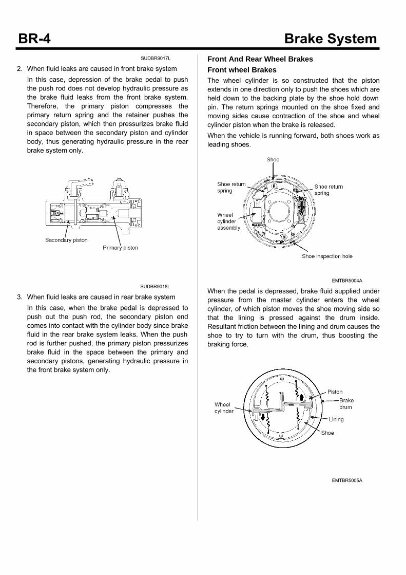
Brake Master Cylinder1. Normal OperationThe tandem type brake master cylinder hasindependent hydraulic systems for front and rearbrakes.Should one of the two hydraulic systems fail, brakingby survived system (front or rear wheels) ensuressafety. When the brake pedal is depressed, theprimary piston is pushed to left, developing hydraulicpressure in the pressure chamber on the primaryside. This pressure directly acts on the secondarypiston to push the secondary piston to left,developing hydraulic pressure also in the pressurechamber on the secondary side. As a result, eachpiston pressurizes brake fluid to generate hydraulicpressure in both front and rear brake systems.
SUDBR9017L
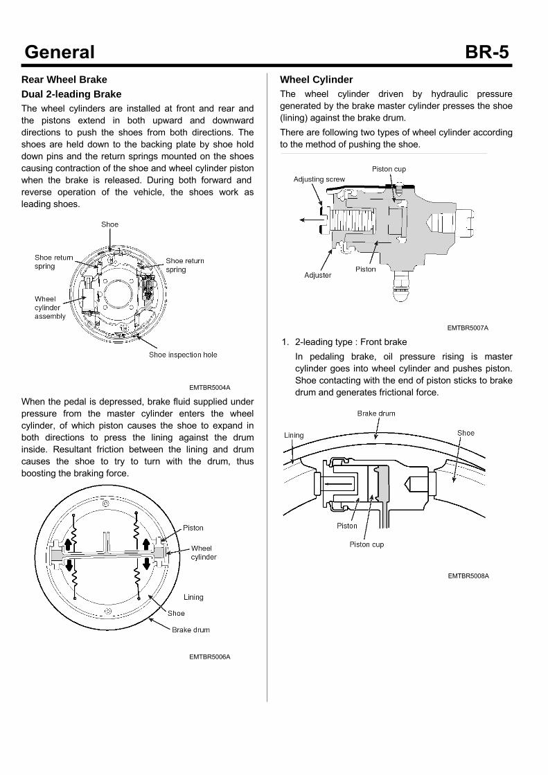
2. When fluid leaks are caused in front brake systemIn this case, depression of the brake pedal to pushthe push rod does not develop hydraulic pressure asthe brake fluid leaks from the front brake system.Therefore, the primary piston compresses theprimary return spring and the retainer pushes thesecondary piston, which then pressurizes brake fluidin space between the secondary piston and cylinderbody, thus generating hydraulic pressure in the rearbrake system only.
SUDBR9018L
3. When fluid leaks are caused in rear brake systemIn this case, when the brake pedal is depressed topush out the push rod, the secondary piston endcomes into contact with the cylinder body since brakefluid in the rear brake system leaks. When the pushrod is further pushed, the primary piston pressurizesbrake fluid in the space between the primary andsecondary pistons, generating hydraulic pressure inthe front brake system only.
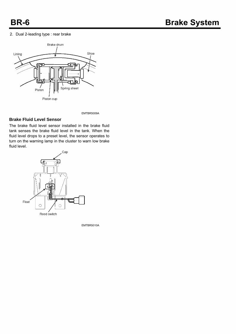
Front And Rear Wheel BrakesFront wheel BrakesThe wheel cylinder is so constructed that the pistonextends in one direction only to push the shoes which areheld down to the backing plate by the shoe hold downpin. The return springs mounted on the shoe fixed andmoving sides cause contraction of the shoe and wheelcylinder piston when the brake is released.When the vehicle is running forward, both shoes work asleading shoes.
EMTBR5004A
When the pedal is depressed, brake fluid supplied underpressure from the master cylinder enters the wheelcylinder, of which piston moves the shoe moving side sothat the lining is pressed against the drum inside.Resultant friction between the lining and drum causes theshoe to try to turn with the drum, thus boosting thebraking force.
EMTBR5005A
Rear Wheel BrakeDual 2-leading BrakeThe wheel cylinders are installed at front and rear andthe pistons extend in both upward and downwarddirections to push the shoes from both directions. Theshoes are held down to the backing plate by shoe holddown pins and the return springs mounted on the shoescausing contraction of the shoe and wheel cylinder pistonwhen the brake is released. During both forward andreverse operation of the vehicle, the shoes work asleading shoes.
EMTBR5004A
When the pedal is depressed, brake fluid supplied underpressure from the master cylinder enters the wheelcylinder, of which piston causes the shoe to expand inboth directions to press the lining against the druminside. Resultant friction between the lining and drumcauses the shoe to try to turn with the drum, thusboosting the braking force.
EMTBR5006A
Wheel CylinderThe wheel cylinder driven by hydraulic pressuregenerated by the brake master cylinder presses the shoe(lining) against the brake drum.There are following two types of wheel cylinder accordingto the method of pushing the shoe.
EMTBR5007A
1. 2-leading type : Front brakeIn pedaling brake, oil pressure rising is mastercylinder goes into wheel cylinder and pushes piston.Shoe contacting with the end of piston sticks to brakedrum and generates frictional force.
EMTBR5008A
2. Dual 2-leading type : rear brake
EMTBR5009A
Brake Fluid Level SensorThe brake fluid level sensor installed in the brake fluidtank senses the brake fluid level in the tank. When thefluid level drops to a preset level, the sensor operates toturn on the warning lamp in the cluster to warn low brakefluid level.
EMTBR5010A
Exhaust Brake
SUDBRA015L
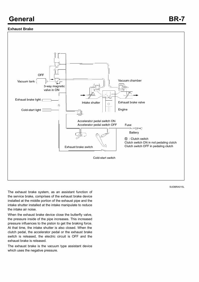
The exhaust brake system, as an assistant function ofthe service brake, comprises of the exhaust brake deviceinstalled at the middle portion of the exhaust pipe and theintake shutter installed at the intake manipulate to reducethe intake air noise.When the exhaust brake device close the butterfly valve,the pressure inside of the pipe increases. This increasedpressure influences to the piston to get the braking force.At that time, the intake shutter is also closed. When theclutch pedal, the accelerator pedal or the exhaust brakeswitch is released, the electric circuit is OFF and theexhaust brake is released.The exhaust brake is the vacuum type assistant devicewhich uses the negative pressure.
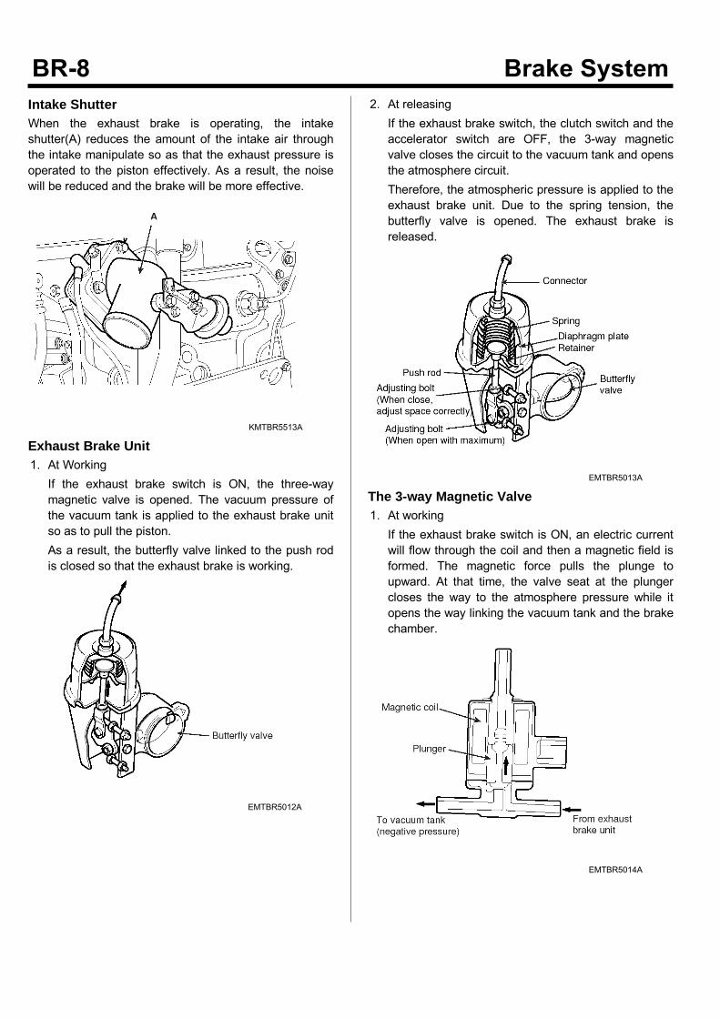
Intake ShutterWhen the exhaust brake is operating, the intakeshutter(A) reduces the amount of the intake air throughthe intake manipulate so as that the exhaust pressure isoperated to the piston effectively. As a result, the noisewill be reduced and the brake will be more effective.
KMTBR5513A
Exhaust Brake Unit1. At WorkingIf the exhaust brake switch is ON, the three-waymagnetic valve is opened. The vacuum pressure ofthe vacuum tank is applied to the exhaust brake unitso as to pull the piston.As a result, the butterfly valve linked to the push rodis closed so that the exhaust brake is working.
EMTBR5012A
2. At releasingIf the exhaust brake switch, the clutch switch and theaccelerator switch are OFF, the 3-way magneticvalve closes the circuit to the vacuum tank and opensthe atmosphere circuit.Therefore, the atmospheric pressure is applied to theexhaust brake unit. Due to the spring tension, thebutterfly valve is opened. The exhaust brake isreleased.
EMTBR5013A
The 3-way Magnetic Valve1. At workingIf the exhaust brake switch is ON, an electric currentwill flow through the coil and then a magnetic field isformed. The magnetic force pulls the plunge toupward. At that time, the valve seat at the plungercloses the way to the atmosphere pressure while itopens the way linking the vacuum tank and the brakechamber.
EMTBR5014A
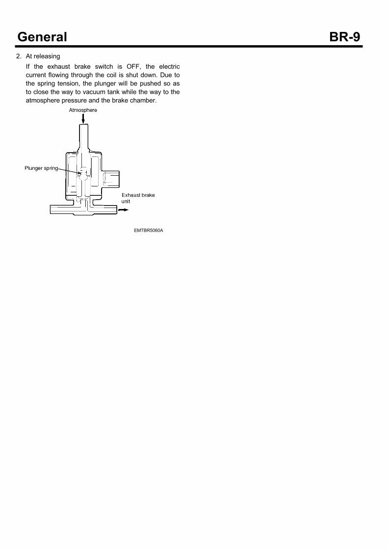
2. At releasingIf the exhaust brake switch is OFF, the electriccurrent flowing through the coil is shut down. Due tothe spring tension, the plunger will be pushed so asto close the way to vacuum tank while the way to theatmosphere pressure and the brake chamber.
EMTBR5060A
LOAD SENSING PROPORTIONING VALVE
SUDBRA021L
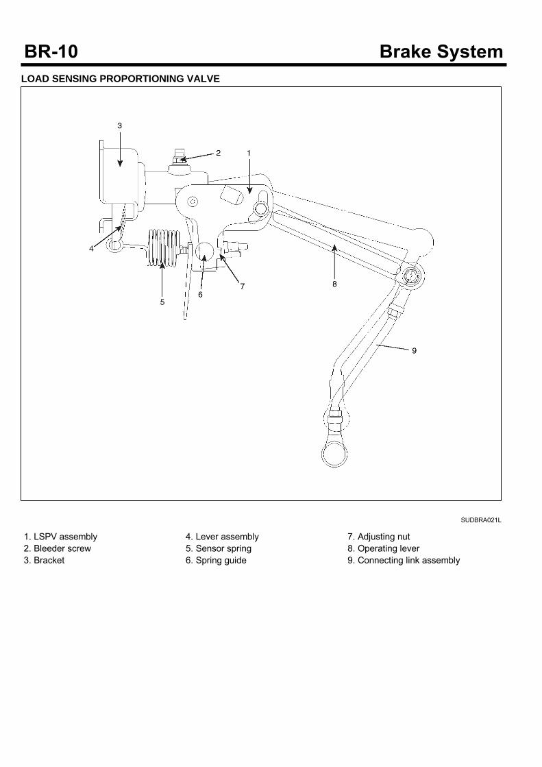
1. LSPV assembly2. Bleeder screw3. Bracket
4. Lever assembly5. Sensor spring6. Spring guide
7. Adjusting nut8. Operating lever9. Connecting link assembly
ConstructionLSPV is consist of sensor part and pressure controllerpart.1. Sensor partIt consists of spring, operating lever, link. It sensesthe height of vehicle with varying according to theamount loads
2. Pressure controller partIt consists of valve stem mechanism for proportioningcontrol of sensor force.
EMTBR5016A
Operating PrincipleLSPV body is mounted in the frame and the end of thelink is mounted in the rear axle. With varying of amountof vehicle load changes the relative position of frame andrear axle, so sensor spring force varies to the valve stem.It controls the rear axle brake fluid pressure.1. Unloaded statusThe sensor spring presses the valve stem slightly, sothe brake fluid pressure is set weakly.
2. Loaded statusThe sensor spring presses the valve stem strongly,so the brake fluid pressure is set highly.
NOTICEDon't loose or don't retighten the adjusting nutcrimping.
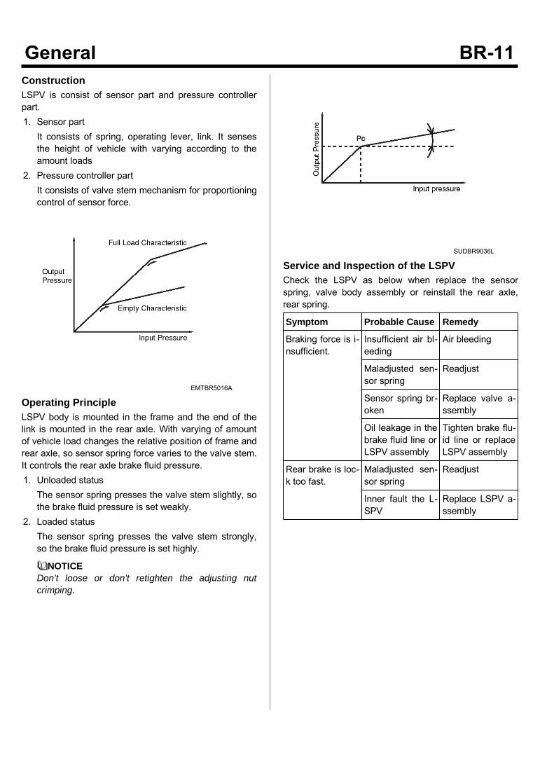
SUDBR9036L
Service and Inspection of the LSPVCheck the LSPV as below when replace the sensorspring, valve body assembly or reinstall the rear axle,rear spring.
Symptom Probable Cause Remedy
Braking force is i-nsufficient.
Insufficient air bl-eeding
Air bleeding
Maladjusted sen-sor spring
Readjust
Sensor spring br-oken
Replace valve a-ssembly
Oil leakage in thebrake fluid line orLSPV assembly
Tighten brake flu-id line or replaceLSPV assembly
Rear brake is loc-k too fast.
Maladjusted sen-sor spring
Readjust
Inner fault the L-SPV
Replace LSPV a-ssembly
PARKING BRAKE GENERAL
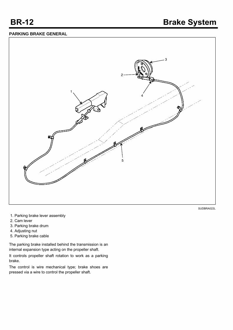
SUDBRA022L
1. Parking brake lever assembly2. Cam lever3. Parking brake drum4. Adjusting nut5. Parking brake cable
The parking brake installed behind the transmission is aninternal expansion type acting on the propeller shaft.It controls propeller shaft rotation to work as a parkingbrake.The control is wire mechanical type; brake shoes arepressed via a wire to control the propeller shaft.
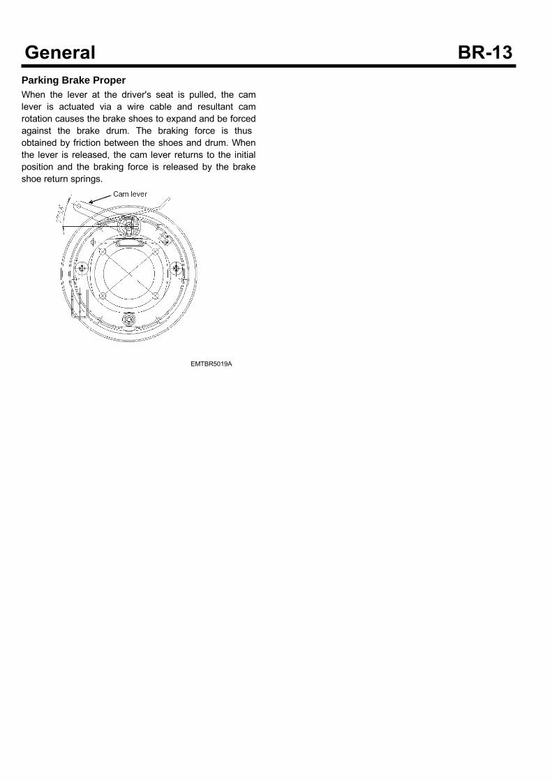
Parking Brake ProperWhen the lever at the driver's seat is pulled, the camlever is actuated via a wire cable and resultant camrotation causes the brake shoes to expand and be forcedagainst the brake drum. The braking force is thusobtained by friction between the shoes and drum. Whenthe lever is released, the cam lever returns to the initialposition and the braking force is released by the brakeshoe return springs.
EMTBR5019A
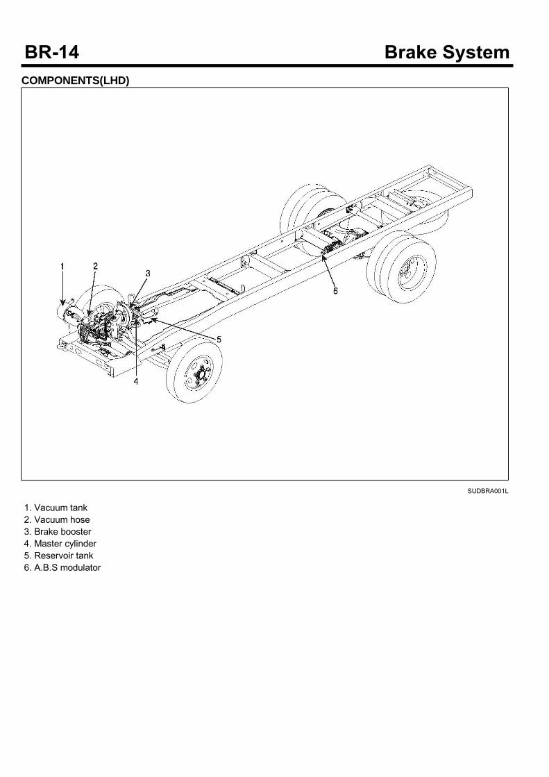
COMPONENTS(LHD)
SUDBRA001L
1. Vacuum tank2. Vacuum hose3. Brake booster4. Master cylinder5. Reservoir tank6. A.B.S modulator
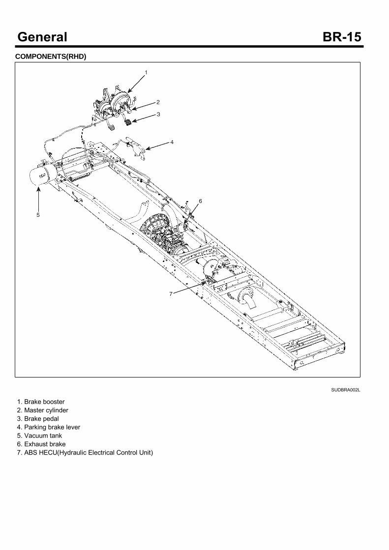
COMPONENTS(RHD)
SUDBRA002L
1. Brake booster2. Master cylinder3. Brake pedal4. Parking brake lever5. Vacuum tank6. Exhaust brake7. ABS HECU(Hydraulic Electrical Control Unit)
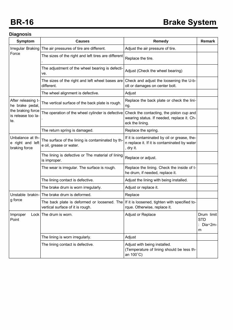
DiagnosisSymptom Causes Remedy Remark
Irregular BrakingForce
The air pressures of tire are different. Adjust the air pressure of tire.
The sizes of the right and left tires are different. Replace the tire.
The adjustment of the wheel bearing is defecti-ve. Adjust (Check the wheel bearing)
The sizes of the right and left wheel bases aredifferent.
Check and adjust the loosening the U-b-olt or damages on center bolt.
The wheel alignment is defective. Adjust
After releasing t-he brake pedal,the braking forceis release too la-te.
The vertical surface of the back plate is rough. Replace the back plate or check the lini-ng.
The operation of the wheel cylinder is defective.
Check the contacting, the piston cup andwearing status. If needed, replace it. Ch-eck the lining.
The return spring is damaged. Replace the spring.
Unbalance at th-e right and leftbraking force
The surface of the lining is contaminated by th-e oil, grease or water.
If it is contaminated by oil or grease, the-n replace it. If it is contaminated by water, dry it.
The lining is defective or The material of liningis improper. Replace or adjust.
The wear is irregular. The surface is rough. Replace the lining. Check the inside of t-he drum, if needed, replace it.
The lining contact is defective. Adjust the lining with being installed.
The brake drum is worn irregularly. Adjust or replace it.
Unstable brakin-g force
The brake drum is deformed. Replace
The back plate is deformed or loosened. Thevertical surface of it is rough.
If it is loosened, tighten with specified to-rque. Otherwise, replace it.
Improper LockPoint
The drum is worn. Adjust or Replace Drum limitSTD: Dia+2m-m
The lining is worn irregularly. Adjust
The lining contact is defective. Adjust with being installed.(Temperature of lining should be less th-an 100°C)
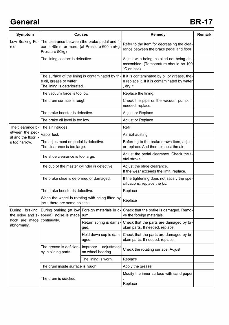
Symptom Causes Remedy Remark
Low Braking Fo-rce
The clearance between the brake pedal and fl-oor is 45mm or more. (at Pressure-600mmHg,Pressure 50kg)
Refer to the item for decreasing the clea-rance between the brake pedal and floor.
The lining contact is defective. Adjust with being installed not being dis-assembled. (Temperature should be 100°C or less)
The surface of the lining is contaminated by th-e oil, grease or water.The lining is deteriorated.
If it is contaminated by oil or grease, the-n replace it. If it is contaminated by water, dry it.
The vacuum force is too low. Replace the lining.
The drum surface is rough. Check the pipe or the vacuum pump. Ifneeded, replace.
The brake booster is defective. Adjust or Replace
The brake oil level is too low. Adjust or Replace
The clearance b-etween the ped-al and the floor i-s too narrow.
The air intrudes. Refill
Vapor lock Air Exhausting
The adjustment on pedal is defective.The clearance is too large.
Referring to the brake drawn item, adjustor replace. And then exhaust the air.
The shoe clearance is too large. Adjust the pedal clearance. Check the t-otal stroke.
The cup of the master cylinder is defective. Adjust the shoe clearance.If the wear exceeds the limit, replace.
The brake shoe is deformed or damaged. If the tightening does not satisfy the spe-cifications, replace the kit.
The brake booster is defective. Replace
When the wheel is rotating with being lifted byjack, there are some noises. Replace
During braking,the noise and s-hock are madeabnormally.
During braking (at lowspeed), noise is madecontinually.
Foreign materials in d-rum
Check that the brake is damaged. Remo-ve the foreign materials.
Return spring is dama-ged.
Check that the parts are damaged by br-oken parts. If needed, replace.
Hold down cup is dam-aged.
Check that the parts are damaged by br-oken parts. If needed, replace.
The grease is deficien-cy in sliding parts.
Improper adjustmenton wheel bearing Check the rotating surface. Adjust
The lining is worn. Replace
The drum inside surface is rough. Apply the grease.
The drum is cracked.Modify the inner surface with sand paper.Replace
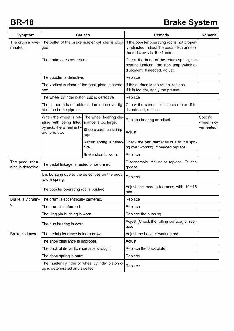
Symptom Causes Remedy Remark
The drum is ove-rheated.
The outlet of the brake master cylinder is clog-ged.
If the booster operating rod is not proper-ly adjusted, adjust the pedal clearance ofthe rod clevis to 10~15mm.
The brake does not return. Check the burst of the return spring, thebearing lubricant, the stop lamp switch a-djustment. If needed, adjust.
The booster is defective. Replace
The vertical surface of the back plate is scratc-hed.
If the surface is too rough, replace.If it is too dry, apply the grease.
The wheel cylinder piston cup is defective. Replace
The oil return has problems due to the over tig-ht of the brake pipe nut.
Check the connector hole diameter. If itis reduced, replace.
When the wheel is rot-ating with being liftedby jack, the wheel is h-ard to rotate.
The wheel bearing cle-arance is too large. Replace bearing or adjust. Specific
wheel is o-verheated.Shoe clearance is imp-
roper. Adjust
Return spring is defec-tive.
Check the part damages due to the spri-ng over working. If needed replace.
Brake shoe is worn. Replace
The pedal retur-ning is defective. The pedal linkage is rusted or deformed.
Disassemble. Adjust or replace. Oil thegrease.
It is bursting due to the defectives on the pedalreturn spring. Replace
The booster operating rod is pushed. Adjust the pedal clearance with 10~15mm.
Brake is vibratin-g.
The drum is eccentrically centered. Replace
The drum is deformed. Replace
The king pin bushing is worn. Replace the bushing
The hub bearing is worn. Adjust (Check the rolling surface) or repl-ace.
Brake is drawn. The pedal clearance is too narrow. Adjust the booster working rod.
The shoe clearance is improper. Adjust
The back plate vertical surface is rough. Replace the back plate.
The shoe spring is burst. Replace
The master cylinder or wheel cylinder piston c-up is deteriorated and swelled. Replace
Symptom Causes Remedy Remark
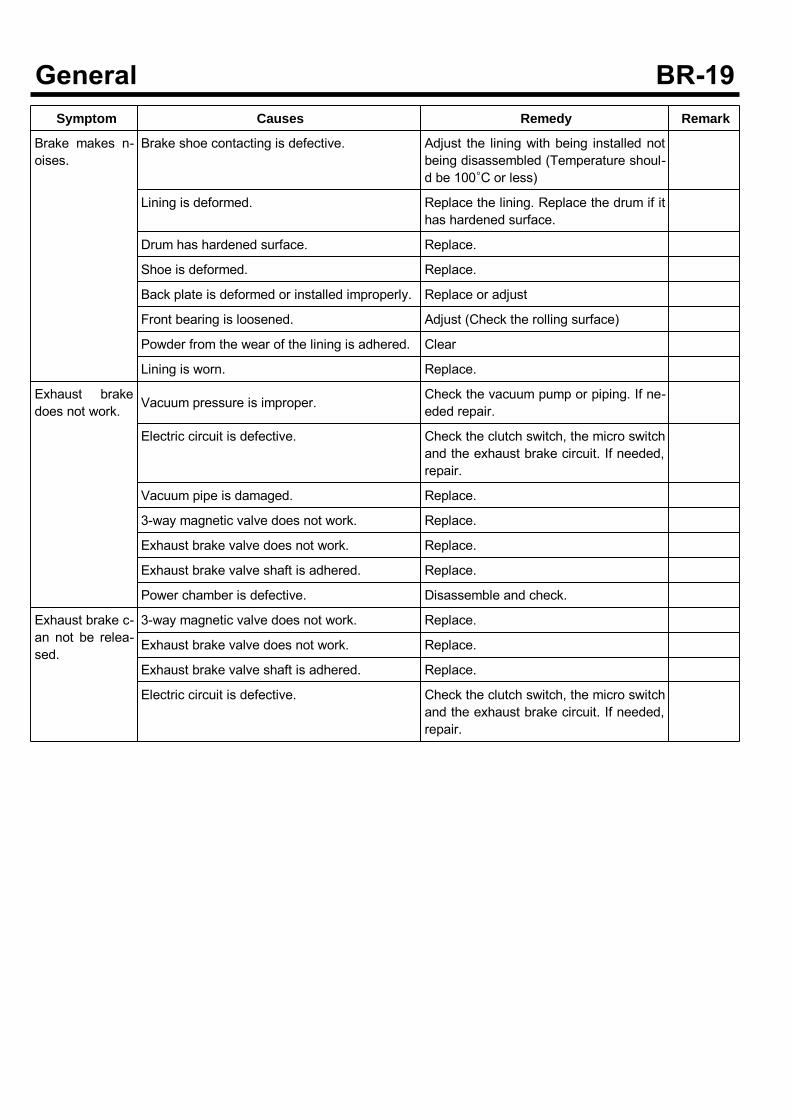
Brake makes n-oises.
Brake shoe contacting is defective. Adjust the lining with being installed notbeing disassembled (Temperature shoul-d be 100°C or less)
Lining is deformed. Replace the lining. Replace the drum if ithas hardened surface.
Drum has hardened surface. Replace.
Shoe is deformed. Replace.
Back plate is deformed or installed improperly. Replace or adjust
Front bearing is loosened. Adjust (Check the rolling surface)
Powder from the wear of the lining is adhered. Clear
Lining is worn. Replace.
Exhaust brakedoes not work. Vacuum pressure is improper. Check the vacuum pump or piping. If ne-
eded repair.
Electric circuit is defective. Check the clutch switch, the micro switchand the exhaust brake circuit. If needed,repair.
Vacuum pipe is damaged. Replace.
3-way magnetic valve does not work. Replace.
Exhaust brake valve does not work. Replace.
Exhaust brake valve shaft is adhered. Replace.
Power chamber is defective. Disassemble and check.
Exhaust brake c-an not be relea-sed.
3-way magnetic valve does not work. Replace.
Exhaust brake valve does not work. Replace.
Exhaust brake valve shaft is adhered. Replace.
Electric circuit is defective. Check the clutch switch, the micro switchand the exhaust brake circuit. If needed,repair.
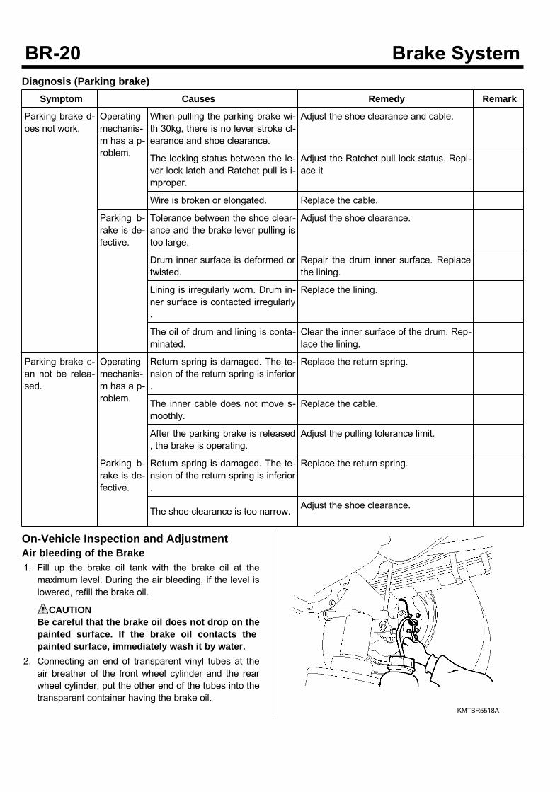
Diagnosis (Parking brake)Symptom Causes Remedy Remark
Parking brake d-oes not work.
Operatingmechanis-m has a p-roblem.
When pulling the parking brake wi-th 30kg, there is no lever stroke cl-earance and shoe clearance.
Adjust the shoe clearance and cable.
The locking status between the le-ver lock latch and Ratchet pull is i-mproper.
Adjust the Ratchet pull lock status. Repl-ace it
Wire is broken or elongated. Replace the cable.
Parking b-rake is de-fective.
Tolerance between the shoe clear-ance and the brake lever pulling istoo large.
Adjust the shoe clearance.
Drum inner surface is deformed ortwisted.
Repair the drum inner surface. Replacethe lining.
Lining is irregularly worn. Drum in-ner surface is contacted irregularly.
Replace the lining.
The oil of drum and lining is conta-minated.
Clear the inner surface of the drum. Rep-lace the lining.
Parking brake c-an not be relea-sed.
Operatingmechanis-m has a p-roblem.
Return spring is damaged. The te-nsion of the return spring is inferior.
Replace the return spring.
The inner cable does not move s-moothly.
Replace the cable.
After the parking brake is released, the brake is operating.
Adjust the pulling tolerance limit.
Parking b-rake is de-fective.
Return spring is damaged. The te-nsion of the return spring is inferior.
Replace the return spring.
The shoe clearance is too narrow. Adjust the shoe clearance.
On-Vehicle Inspection and AdjustmentAir bleeding of the Brake1. Fill up the brake oil tank with the brake oil at themaximum level. During the air bleeding, if the level islowered, refill the brake oil.
CAUTIONBe careful that the brake oil does not drop on thepainted surface. If the brake oil contacts thepainted surface, immediately wash it by water.
2. Connecting an end of transparent vinyl tubes at theair breather of the front wheel cylinder and the rearwheel cylinder, put the other end of the tubes into thetransparent container having the brake oil.
KMTBR5518A
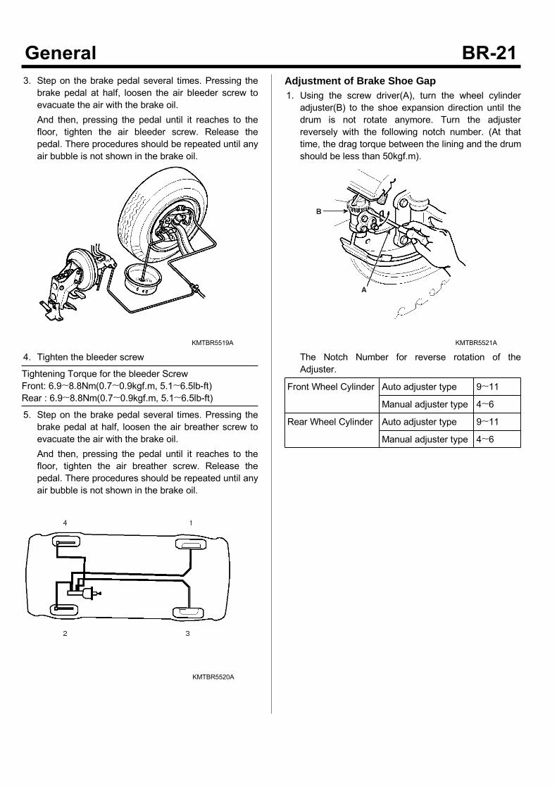
3. Step on the brake pedal several times. Pressing thebrake pedal at half, loosen the air bleeder screw toevacuate the air with the brake oil.And then, pressing the pedal until it reaches to thefloor, tighten the air bleeder screw. Release thepedal. There procedures should be repeated until anyair bubble is not shown in the brake oil.
KMTBR5519A
4. Tighten the bleeder screw
Tightening Torque for the bleeder ScrewFront: 6.9~8.8Nm(0.7~0.9kgf.m, 5.1~6.5lb-ft)Rear : 6.9~8.8Nm(0.7~0.9kgf.m, 5.1~6.5lb-ft)
5. Step on the brake pedal several times. Pressing thebrake pedal at half, loosen the air breather screw toevacuate the air with the brake oil.And then, pressing the pedal until it reaches to thefloor, tighten the air breather screw. Release thepedal. There procedures should be repeated until anyair bubble is not shown in the brake oil.
KMTBR5520A
Adjustment of Brake Shoe Gap1. Using the screw driver(A), turn the wheel cylinderadjuster(B) to the shoe expansion direction until thedrum is not rotate anymore. Turn the adjusterreversely with the following notch number. (At thattime, the drag torque between the lining and the drumshould be less than 50kgf.m).
KMTBR5521A
The Notch Number for reverse rotation of theAdjuster.
Front Wheel Cylinder Auto adjuster type 9~11
Manual adjuster type 4~6
Rear Wheel Cylinder Auto adjuster type 9~11
Manual adjuster type 4~6
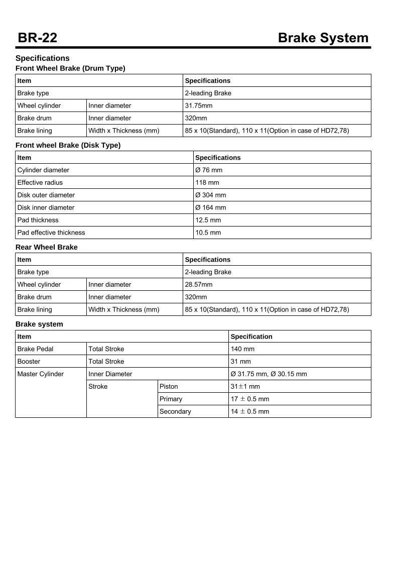
SpecificationsFront Wheel Brake (Drum Type)Item Specifications
Brake type 2-leading Brake
Wheel cylinder Inner diameter 31.75mm
Brake drum Inner diameter 320mm
Brake lining Width x Thickness (mm) 85 x 10(Standard), 110 x 11(Option in case of HD72,78)
Front wheel Brake (Disk Type)Item Specifications
Cylinder diameter Ø 76 mm
Effective radius 118 mm
Disk outer diameter Ø 304 mm
Disk inner diameter Ø 164 mm
Pad thickness 12.5 mm
Pad effective thickness 10.5 mm
Rear Wheel BrakeItem Specifications
Brake type 2-leading Brake
Wheel cylinder Inner diameter 28.57mm
Brake drum Inner diameter 320mm
Brake lining Width x Thickness (mm) 85 x 10(Standard), 110 x 11(Option in case of HD72,78)
Brake systemItem Specification
Brake Pedal Total Stroke 140 mm
Booster Total Stroke 31 mm
Master Cylinder Inner Diameter Ø 31.75 mm, Ø 30.15 mm
Stroke Piston 31±1 mm
Primary 17 ± 0.5 mm
Secondary 14 ± 0.5 mm
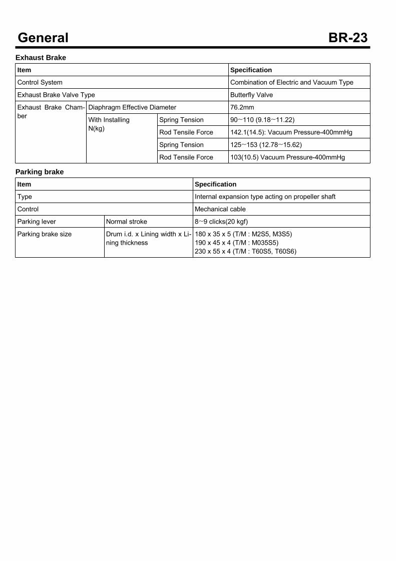
Exhaust BrakeItem Specification
Control System Combination of Electric and Vacuum Type
Exhaust Brake Valve Type Butterfly Valve
Exhaust Brake Cham-ber
Diaphragm Effective Diameter 76.2mm
With InstallingN(kg)
Spring Tension 90~110 (9.18~11.22)
Rod Tensile Force 142.1(14.5): Vacuum Pressure-400mmHg
Spring Tension 125~153 (12.78~15.62)
Rod Tensile Force 103(10.5) Vacuum Pressure-400mmHg
Parking brakeItem Specification
Type Internal expansion type acting on propeller shaft
Control Mechanical cable
Parking lever Normal stroke 8~9 clicks(20 kgf)
Parking brake size Drum i.d. x Lining width x Li-ning thickness
180 x 35 x 5 (T/M : M2S5, M3S5)190 x 45 x 4 (T/M : M035S5)230 x 55 x 4 (T/M : T60S5, T60S6)
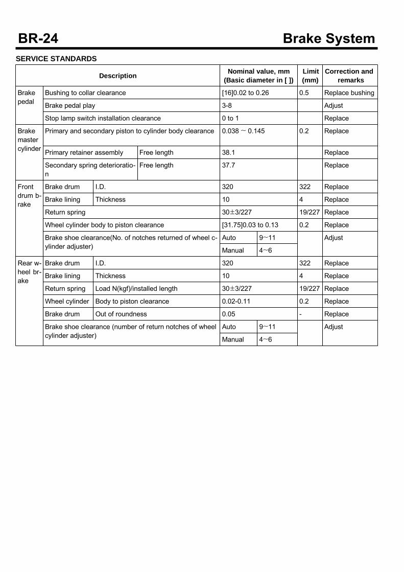
SERVICE STANDARDS
Description Nominal value, mm(Basic diameter in [ ])
Limit(mm)
Correction andremarks
Brakepedal
Bushing to collar clearance [16]0.02 to 0.26 0.5 Replace bushing
Brake pedal play 3-8 Adjust
Stop lamp switch installation clearance 0 to 1 Replace
Brakemastercylinder
Primary and secondary piston to cylinder body clearance 0.038 ~ 0.145 0.2 Replace
Primary retainer assembly Free length 38.1 Replace
Secondary spring deterioratio-n
Free length 37.7 Replace
Frontdrum b-rake
Brake drum I.D. 320 322 Replace
Brake lining Thickness 10 4 Replace
Return spring 30±3/227 19/227 Replace
Wheel cylinder body to piston clearance [31.75]0.03 to 0.13 0.2 Replace
Brake shoe clearance(No. of notches returned of wheel c-ylinder adjuster)
Auto 9~11 Adjust
Manual 4~6
Rear w-heel br-ake
Brake drum I.D. 320 322 Replace
Brake lining Thickness 10 4 Replace
Return spring Load N(kgf)/installed length 30±3/227 19/227 Replace
Wheel cylinder Body to piston clearance 0.02-0.11 0.2 Replace
Brake drum Out of roundness 0.05 - Replace
Brake shoe clearance (number of return notches of wheelcylinder adjuster)
Auto 9~11 Adjust
Manual 4~6
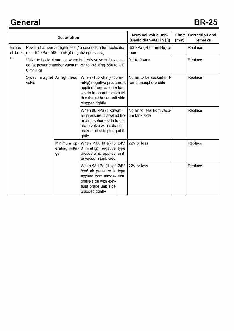
Description Nominal value, mm(Basic diameter in [ ])
Limit(mm)
Correction andremarks
Exhau-st brak-e
Power chamber air tightness [15 seconds after applicatio-n of -67 kPa (-500 mmHg) negative pressure]
-63 kPa (-475 mmHg) ormore
Replace
Valve to body clearance when butterfly valve is fully clos-ed [at power chamber vacuum -87 to -93 kPa(-650 to -700 mmHg)
0.1 to 0.4mm Replace
3-way magnetvalve
Air tightness When -100 kPa (-750 m-mHg) negative pressure isapplied from vacuum tan-k side to operate valve wi-th exhaust brake unit sideplugged tightly
No air to be sucked in f-rom atmosphere side
Replace
When 98 kPa (1 kgf/cm²air pressure is applied fro-m atmosphere side to op-erate valve with exhaustbrake unit side plugged ti-ghtly
No air to leak from vacu-um tank side
Replace
Minimum op-erating volta-ge
When -100 kPa(-750 mmHg) negativepressure is appliedto vacuum tank side
24Vtypeunit
22V or less Replace
When 98 kPa (1 kgf/cm² air pressure isapplied from atmos-phere side with exh-aust brake unit sideplugged tightly
24Vtypeunit
22V or less Replace
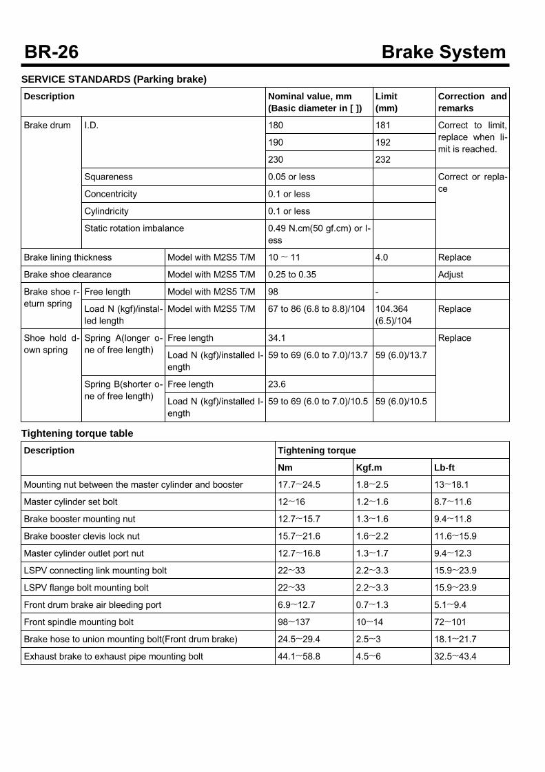
SERVICE STANDARDS (Parking brake)Description Nominal value, mm
(Basic diameter in [ ])Limit(mm)
Correction andremarks
Brake drum I.D. 180 181 Correct to limit,replace when li-mit is reached.
190 192
230 232
Squareness 0.05 or less Correct or repla-ceConcentricity 0.1 or less
Cylindricity 0.1 or less
Static rotation imbalance 0.49 N.cm(50 gf.cm) or l-ess
Brake lining thickness Model with M2S5 T/M 10 ~ 11 4.0 Replace
Brake shoe clearance Model with M2S5 T/M 0.25 to 0.35 Adjust
Brake shoe r-eturn spring
Free length Model with M2S5 T/M 98 -
Load N (kgf)/instal-led length
Model with M2S5 T/M 67 to 86 (6.8 to 8.8)/104 104.364(6.5)/104
Replace
Shoe hold d-own spring
Spring A(longer o-ne of free length)
Free length 34.1 Replace
Load N (kgf)/installed l-ength
59 to 69 (6.0 to 7.0)/13.7 59 (6.0)/13.7
Spring B(shorter o-ne of free length)
Free length 23.6
Load N (kgf)/installed l-ength
59 to 69 (6.0 to 7.0)/10.5 59 (6.0)/10.5
Tightening torque tableDescription Tightening torque
Nm Kgf.m Lb-ft
Mounting nut between the master cylinder and booster 17.7~24.5 1.8~2.5 13~18.1
Master cylinder set bolt 12~16 1.2~1.6 8.7~11.6
Brake booster mounting nut 12.7~15.7 1.3~1.6 9.4~11.8
Brake booster clevis lock nut 15.7~21.6 1.6~2.2 11.6~15.9
Master cylinder outlet port nut 12.7~16.8 1.3~1.7 9.4~12.3
LSPV connecting link mounting bolt 22~33 2.2~3.3 15.9~23.9
LSPV flange bolt mounting bolt 22~33 2.2~3.3 15.9~23.9
Front drum brake air bleeding port 6.9~12.7 0.7~1.3 5.1~9.4
Front spindle mounting bolt 98~137 10~14 72~101
Brake hose to union mounting bolt(Front drum brake) 24.5~29.4 2.5~3 18.1~21.7
Exhaust brake to exhaust pipe mounting bolt 44.1~58.8 4.5~6 32.5~43.4
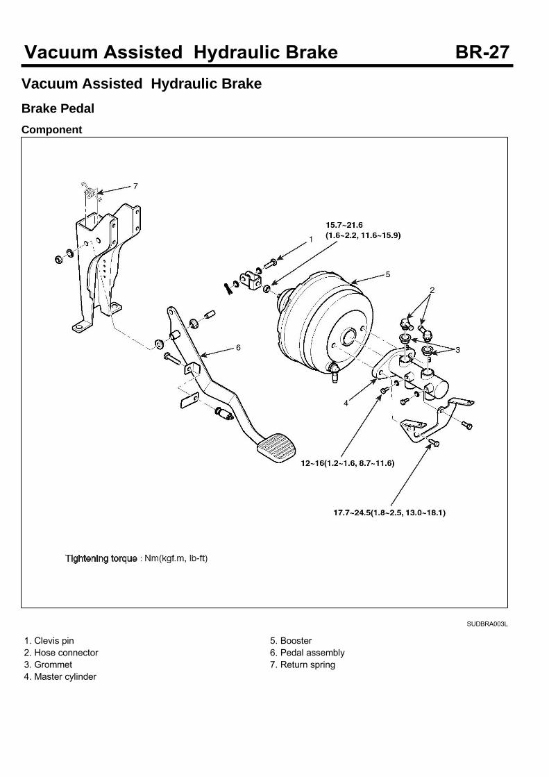
Vacuum Assisted Hydraulic BrakeBrake PedalComponent
SUDBRA003L
1. Clevis pin2. Hose connector3. Grommet4. Master cylinder
5. Booster6. Pedal assembly7. Return spring
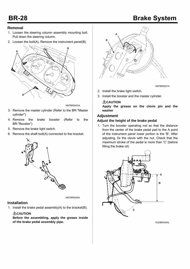
Removal1. Loosen the steering column assembly mounting bolt.Pull down the steering column.
2. Loosen the bolt(A), Remove the instrument panel(B).
KMTBR5003A
3. Remove the master cylinder (Refer to the BR-"Mastercylinder")
4. Remove the brake booster (Refer to theBR-"Booster")
5. Remove the brake light switch.6. Remove the shaft bolt(A) connected to the bracket.
KMTBR5040A
Installation1. Install the brake pedal assembly(A) to the bracket(B).
CAUTIONBefore the assembling, apply the grease insideof the brake pedal assembly pipe.
KMTBR5527A
2. Install the brake light switch.3. Install the booster and the master cylinder.
CAUTIONApply the grease on the clevis pin and thewasher
AdjustmentAdjust the height of the brake pedal1. Turn the booster operating rod so that the distancefrom the center of the brake pedal pad to the A pointof the instrument panel lower portion is the 'B'. Afteradjusting, fix the clevis with the nut. Check that themaximum stroke of the pedal is more than 'C' (beforefilling the brake oil)
SUDBRA004L
Engine B(mm) C(mm)
Non A-BS
D4DD, D4GA 280±2 140±4
The others 273±3 140±4
ABS D4DD, D4GA 280±2 140±4
The others 273±2 140±4
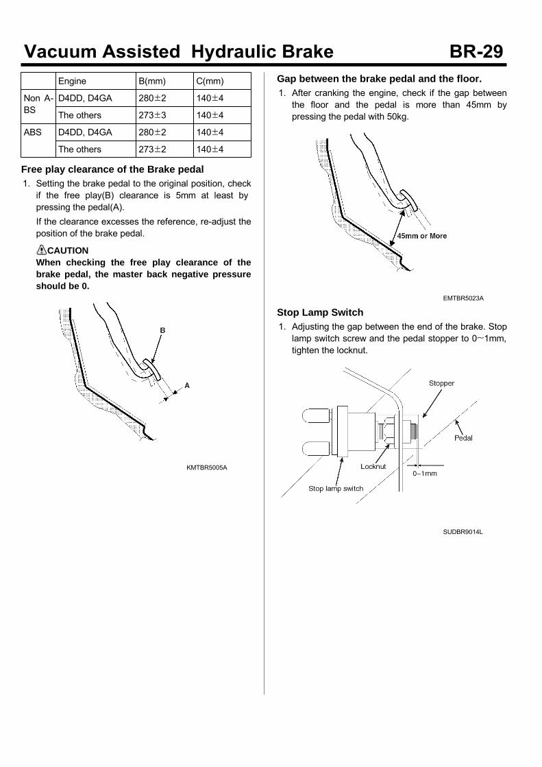
Free play clearance of the Brake pedal1. Setting the brake pedal to the original position, checkif the free play(B) clearance is 5mm at least bypressing the pedal(A).If the clearance excesses the reference, re-adjust theposition of the brake pedal.
CAUTIONWhen checking the free play clearance of thebrake pedal, the master back negative pressureshould be 0.
KMTBR5005A
Gap between the brake pedal and the floor.1. After cranking the engine, check if the gap betweenthe floor and the pedal is more than 45mm bypressing the pedal with 50kg.
EMTBR5023A
Stop Lamp Switch1. Adjusting the gap between the end of the brake. Stoplamp switch screw and the pedal stopper to 0~1mm,tighten the locknut.
SUDBR9014L
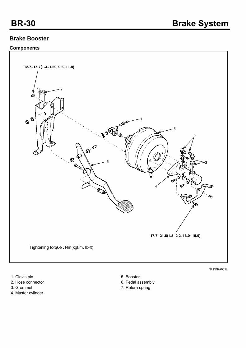
Brake BoosterComponents
SUDBRA005L
1. Clevis pin2. Hose connector3. Grommet4. Master cylinder
5. Booster6. Pedal assembly7. Return spring
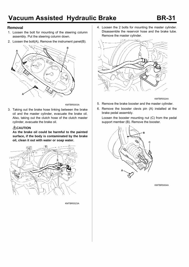
Removal1. Loosen the bolt for mounting of the steering columnassembly. Put the steering column down.
2. Loosen the bolt(A), Remove the instrument panel(B).
KMTBR5003A
3. Taking out the brake hose linking between the brakeoil and the master cylinder, evacuate the brake oil.Also, taking out the clutch hose of the clutch mastercylinder, evacuate the brake oil.
CAUTIONAs the brake oil could be harmful to the paintedsurface, if the body is contaminated by the brakeoil, clean it out with water or soap water.
KMTBR5523A
4. Loosen the 2 bolts for mounting the master cylinder.Disassemble the reservoir hose and the brake tube.Remove the master cylinder.
KMTBR5524A
5. Remove the brake booster and the master cylinder.6. Remove the booster clevis pin (A) installed at thebrake pedal assembly.Loosen the booster mounting nut (C) from the pedalsupport member (B). Remove the booster.
KMTBR5004A
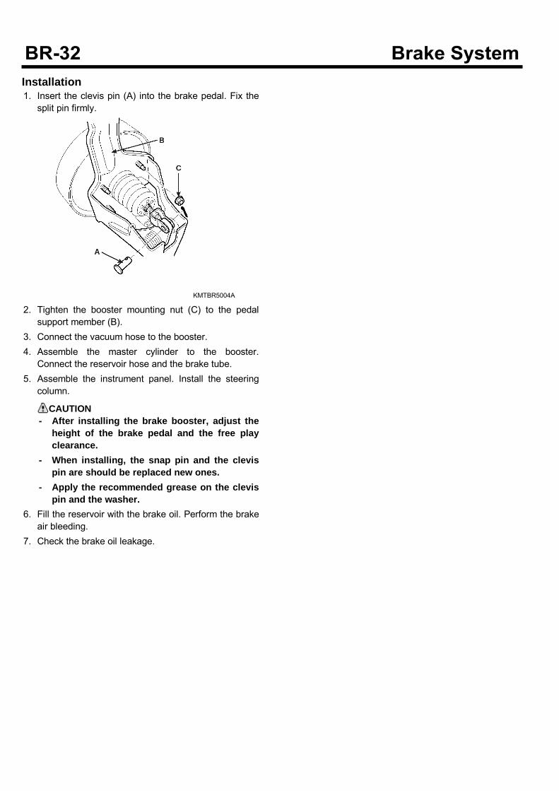
Installation1. Insert the clevis pin (A) into the brake pedal. Fix thesplit pin firmly.
KMTBR5004A
2. Tighten the booster mounting nut (C) to the pedalsupport member (B).
3. Connect the vacuum hose to the booster.4. Assemble the master cylinder to the booster.Connect the reservoir hose and the brake tube.
5. Assemble the instrument panel. Install the steeringcolumn.
CAUTION- After installing the brake booster, adjust the
height of the brake pedal and the free playclearance.
- When installing, the snap pin and the clevispin are should be replaced new ones.
- Apply the recommended grease on the clevispin and the washer.
6. Fill the reservoir with the brake oil. Perform the brakeair bleeding.
7. Check the brake oil leakage.
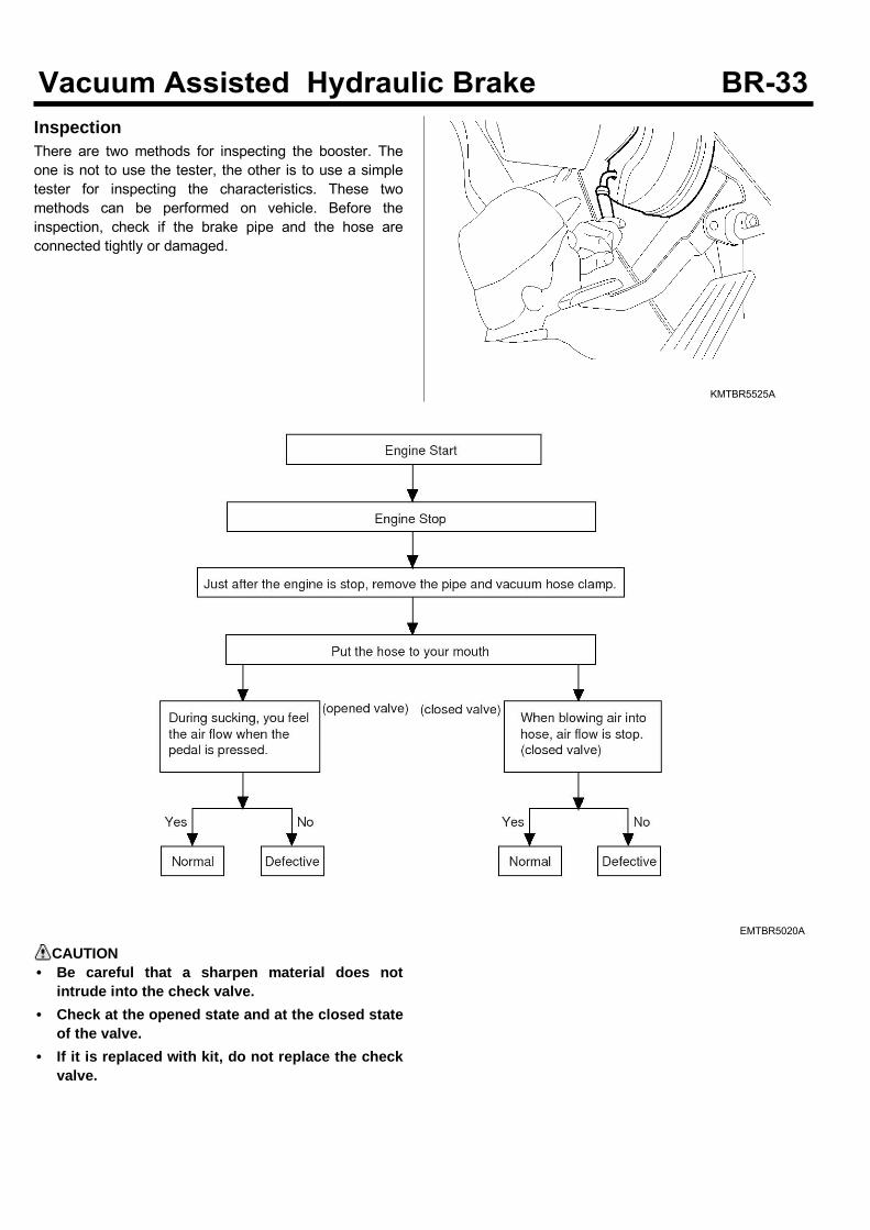
InspectionThere are two methods for inspecting the booster. Theone is not to use the tester, the other is to use a simpletester for inspecting the characteristics. These twomethods can be performed on vehicle. Before theinspection, check if the brake pipe and the hose areconnected tightly or damaged.
KMTBR5525A
EMTBR5020A
CAUTION• Be careful that a sharpen material does not
intrude into the check valve.• Check at the opened state and at the closed state
of the valve.• If it is replaced with kit, do not replace the check
valve.
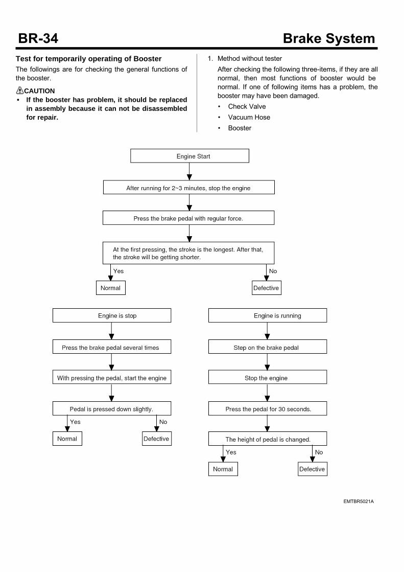
Test for temporarily operating of BoosterThe followings are for checking the general functions ofthe booster.
CAUTION• If the booster has problem, it should be replaced
in assembly because it can not be disassembledfor repair.
1. Method without testerAfter checking the following three-items, if they are allnormal, then most functions of booster would benormal. If one of following items has a problem, thebooster may have been damaged.• Check Valve• Vacuum Hose• Booster
EMTBR5021A
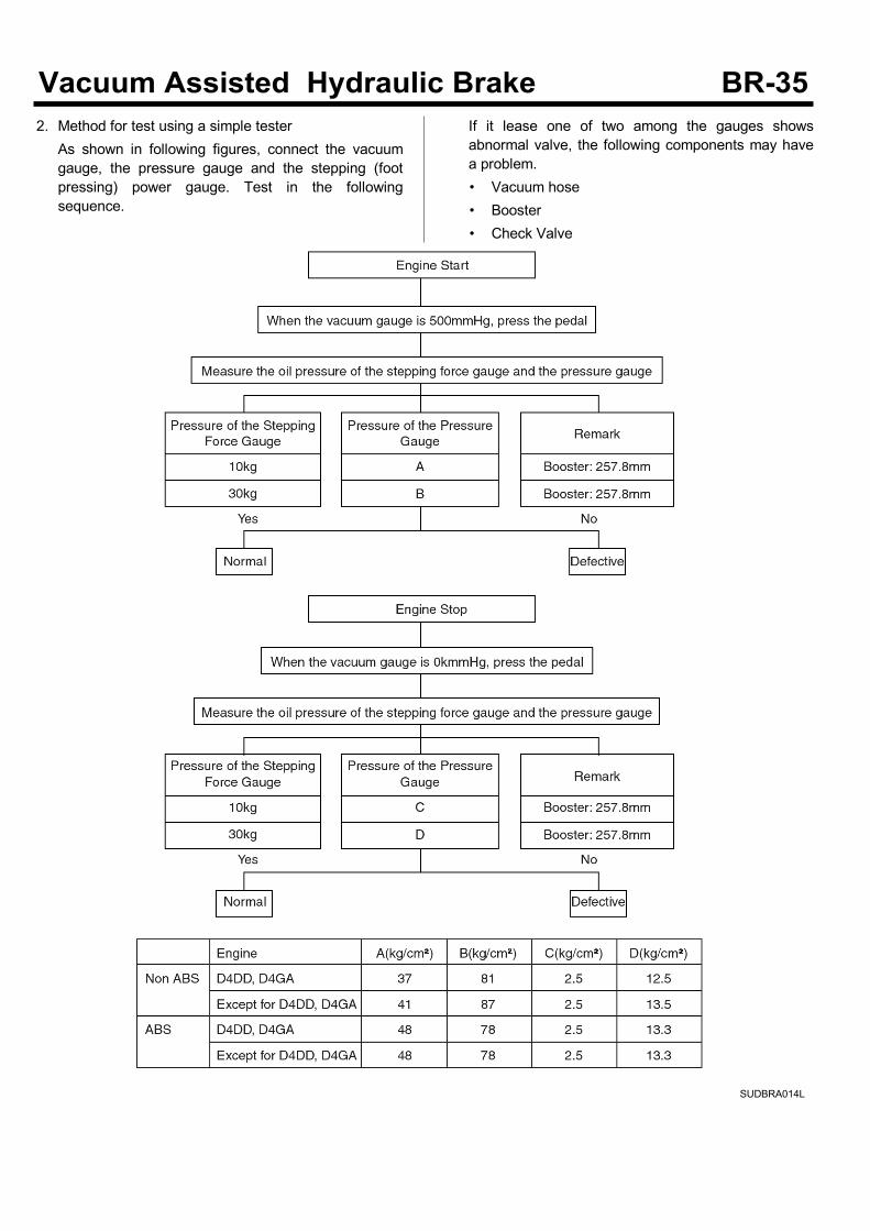
2. Method for test using a simple testerAs shown in following figures, connect the vacuumgauge, the pressure gauge and the stepping (footpressing) power gauge. Test in the followingsequence.
If it lease one of two among the gauges showsabnormal valve, the following components may havea problem.• Vacuum hose• Booster• Check Valve
SUDBRA014L
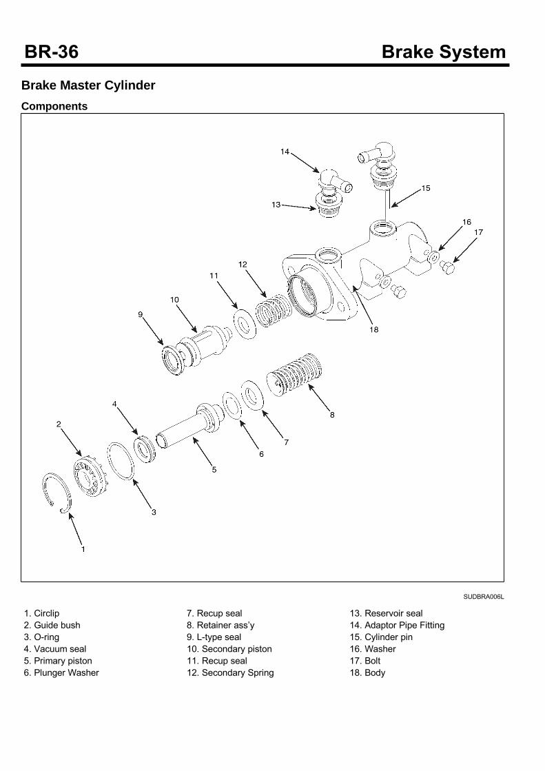
Brake Master CylinderComponents
SUDBRA006L
1. Circlip2. Guide bush3. O-ring4. Vacuum seal5. Primary piston6. Plunger Washer
7. Recup seal8. Retainer ass’y9. L-type seal10. Secondary piston11. Recup seal12. Secondary Spring
13. Reservoir seal14. Adaptor Pipe Fitting15. Cylinder pin16. Washer17. Bolt18. Body
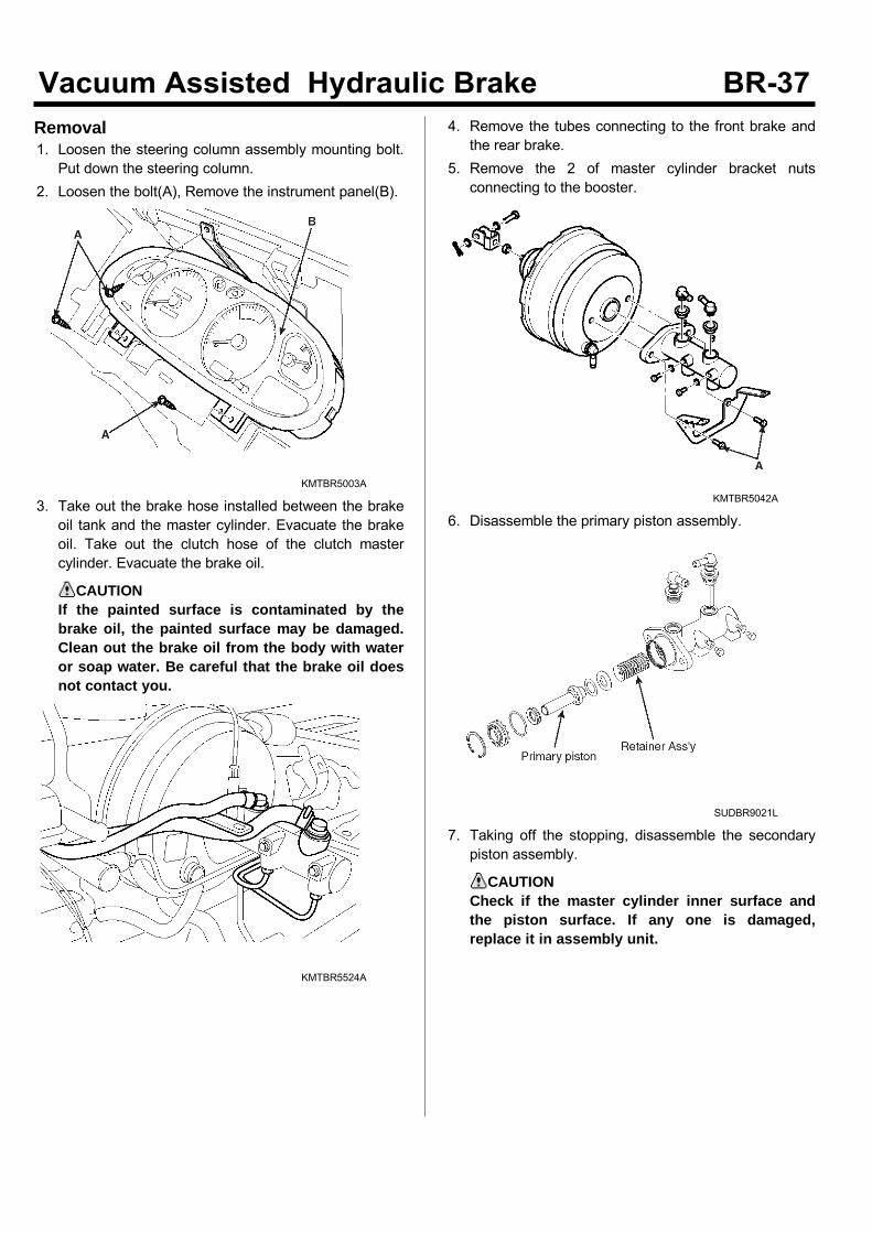
Removal1. Loosen the steering column assembly mounting bolt.Put down the steering column.
2. Loosen the bolt(A), Remove the instrument panel(B).
KMTBR5003A
3. Take out the brake hose installed between the brakeoil tank and the master cylinder. Evacuate the brakeoil. Take out the clutch hose of the clutch mastercylinder. Evacuate the brake oil.
CAUTIONIf the painted surface is contaminated by thebrake oil, the painted surface may be damaged.Clean out the brake oil from the body with wateror soap water. Be careful that the brake oil doesnot contact you.
KMTBR5524A
4. Remove the tubes connecting to the front brake andthe rear brake.
5. Remove the 2 of master cylinder bracket nutsconnecting to the booster.
KMTBR5042A
6. Disassemble the primary piston assembly.
SUDBR9021L
7. Taking off the stopping, disassemble the secondarypiston assembly.
CAUTIONCheck if the master cylinder inner surface andthe piston surface. If any one is damaged,replace it in assembly unit.
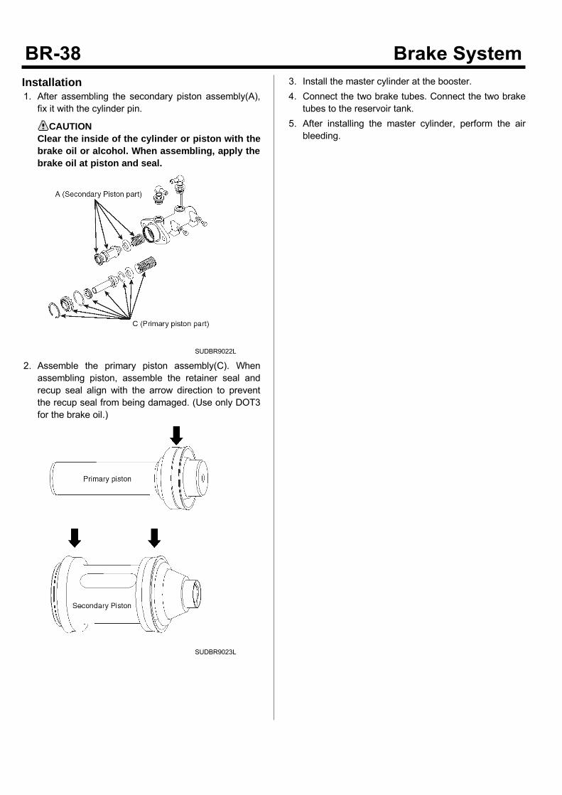
Installation1. After assembling the secondary piston assembly(A),fix it with the cylinder pin.
CAUTIONClear the inside of the cylinder or piston with thebrake oil or alcohol. When assembling, apply thebrake oil at piston and seal.
SUDBR9022L
2. Assemble the primary piston assembly(C). Whenassembling piston, assemble the retainer seal andrecup seal align with the arrow direction to preventthe recup seal from being damaged. (Use only DOT3for the brake oil.)
SUDBR9023L
3. Install the master cylinder at the booster.4. Connect the two brake tubes. Connect the two braketubes to the reservoir tank.
5. After installing the master cylinder, perform the airbleeding.
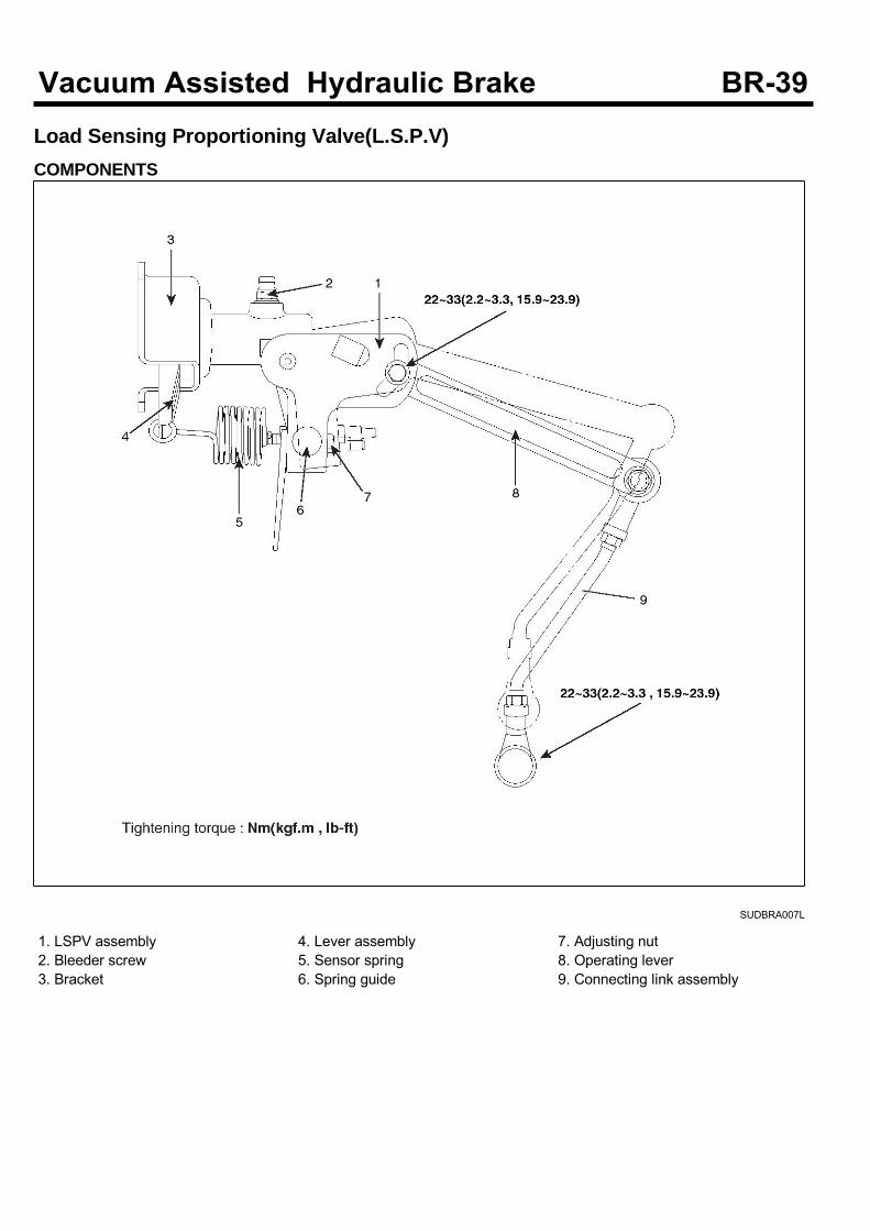
Load Sensing Proportioning Valve(L.S.P.V)COMPONENTS
SUDBRA007L
1. LSPV assembly2. Bleeder screw3. Bracket
4. Lever assembly5. Sensor spring6. Spring guide
7. Adjusting nut8. Operating lever9. Connecting link assembly
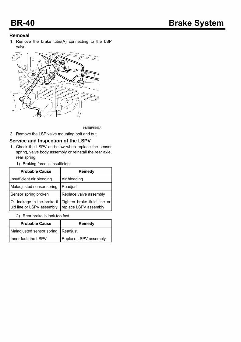
Removal1. Remove the brake tube(A) connecting to the LSPvalve.
KMTBR5557A
2. Remove the LSP valve mounting bolt and nut.
Service and Inspection of the LSPV1. Check the LSPV as below when replace the sensorspring, valve body assembly or reinstall the rear axle,rear spring.1) Braking force is insufficient
Probable Cause Remedy
Insufficient air bleeding Air bleeding
Maladjusted sensor spring Readjust
Sensor spring broken Replace valve assembly
Oil leakage in the brake fl-uid line or LSPV assembly
Tighten brake fluid line orreplace LSPV assembly
2) Rear brake is lock too fast
Probable Cause Remedy
Maladjusted sensor spring Readjust
Inner fault the LSPV Replace LSPV assembly
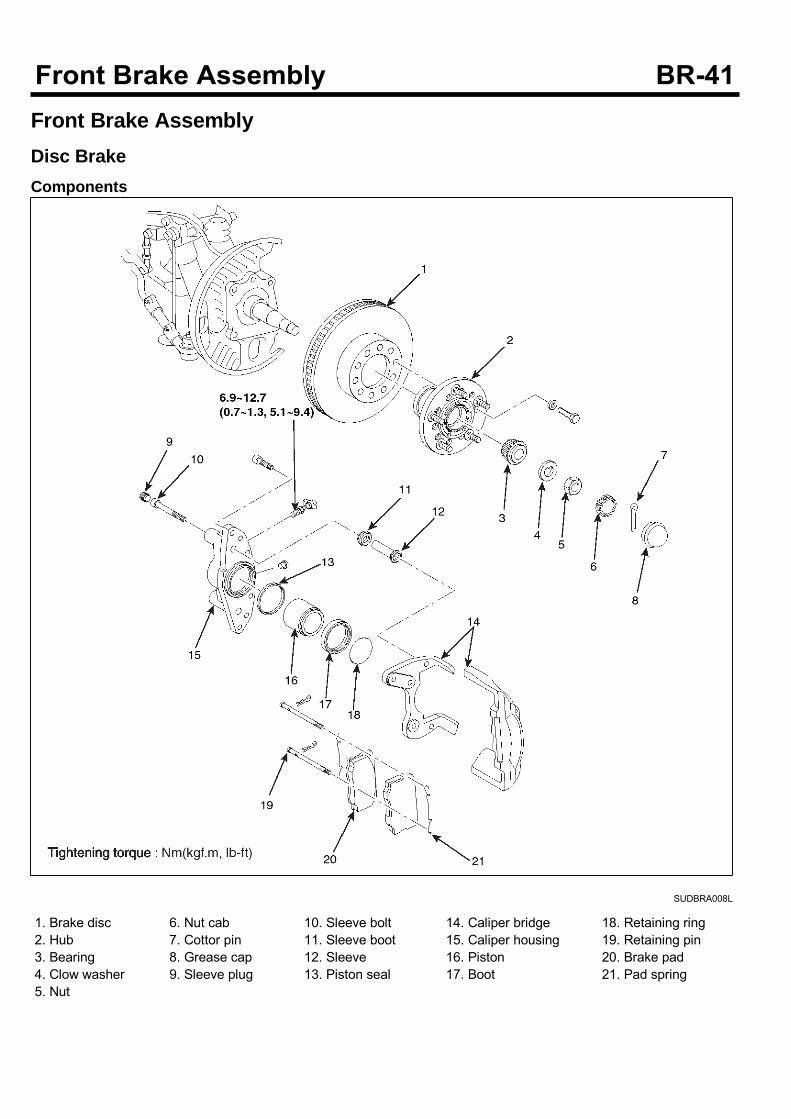
Front Brake AssemblyDisc BrakeComponents
SUDBRA008L
1. Brake disc2. Hub3. Bearing4. Clow washer5. Nut
6. Nut cab7. Cottor pin8. Grease cap9. Sleeve plug
10. Sleeve bolt11. Sleeve boot12. Sleeve13. Piston seal
14. Caliper bridge15. Caliper housing16. Piston17. Boot
18. Retaining ring19. Retaining pin20. Brake pad21. Pad spring
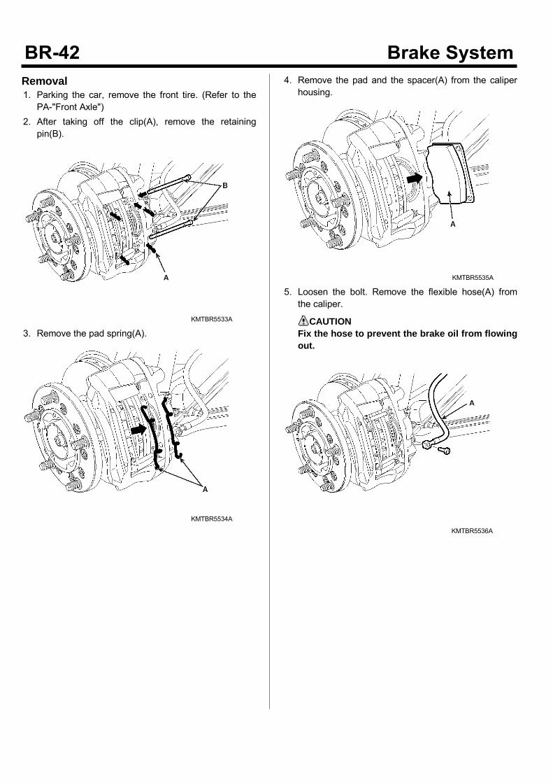
Removal1. Parking the car, remove the front tire. (Refer to thePA-"Front Axle")
2. After taking off the clip(A), remove the retainingpin(B).
KMTBR5533A
3. Remove the pad spring(A).
KMTBR5534A
4. Remove the pad and the spacer(A) from the caliperhousing.
KMTBR5535A
5. Loosen the bolt. Remove the flexible hose(A) fromthe caliper.
CAUTIONFix the hose to prevent the brake oil from flowingout.
KMTBR5536A
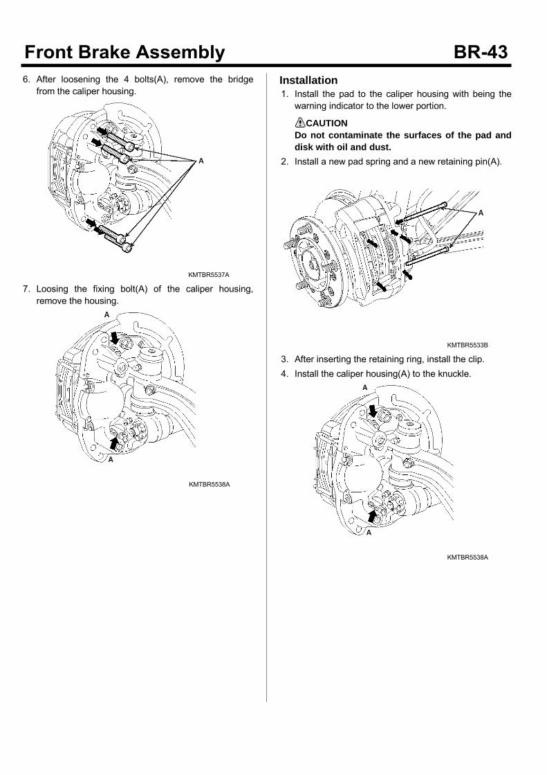
6. After loosening the 4 bolts(A), remove the bridgefrom the caliper housing.
KMTBR5537A
7. Loosing the fixing bolt(A) of the caliper housing,remove the housing.
KMTBR5538A
Installation1. Install the pad to the caliper housing with being thewarning indicator to the lower portion.
CAUTIONDo not contaminate the surfaces of the pad anddisk with oil and dust.
2. Install a new pad spring and a new retaining pin(A).
KMTBR5533B
3. After inserting the retaining ring, install the clip.4. Install the caliper housing(A) to the knuckle.
KMTBR5538A
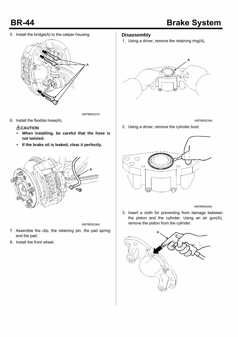
5. Install the bridge(A) to the caliper housing.
KMTBR5537A
6. Install the flexible hose(A).
CAUTION• When installing, be careful that the hose is
not twisted.• If the brake oil is leaked, clear it perfectly.
KMTBR5536A
7. Assemble the clip, the retaining pin, the pad springand the pad.
8. Install the front wheel.
Disassembly1. Using a driver, remove the retaining ring(A).
KMTBR5539A
2. Using a driver, remove the cylinder boot.
KMTBR5540A
3. Insert a cloth for preventing from damage betweenthe piston and the cylinder. Using an air gun(A),remove the piston from the cylinder.
KMTBR5541A
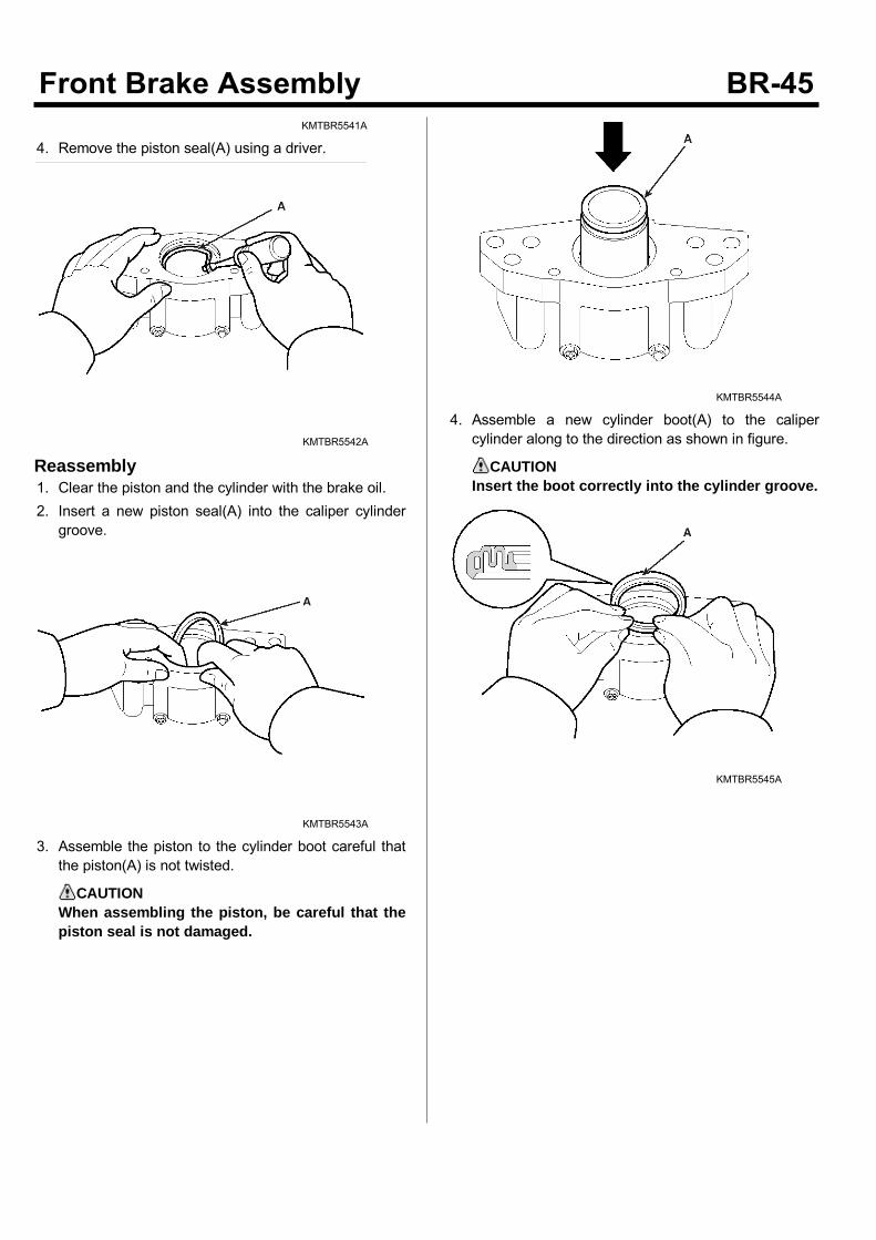
4. Remove the piston seal(A) using a driver.
KMTBR5542A
Reassembly1. Clear the piston and the cylinder with the brake oil.2. Insert a new piston seal(A) into the caliper cylindergroove.
KMTBR5543A
3. Assemble the piston to the cylinder boot careful thatthe piston(A) is not twisted.
CAUTIONWhen assembling the piston, be careful that thepiston seal is not damaged.
KMTBR5544A
4. Assemble a new cylinder boot(A) to the calipercylinder along to the direction as shown in figure.
CAUTIONInsert the boot correctly into the cylinder groove.
KMTBR5545A
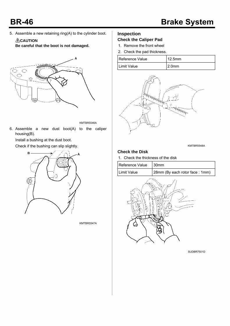
5. Assemble a new retaining ring(A) to the cylinder boot.
CAUTIONBe careful that the boot is not damaged.
KMTBR5546A
6. Assemble a new dust boot(A) to the caliperhousing(B).Install a bushing at the dust boot.Check if the bushing can slip slightly.
KMTBR5547A
InspectionCheck the Caliper Pad1. Remove the front wheel2. Check the pad thickness.
Reference Value 12.5mm
Limit Value 2.0mm
KMTBR5548A
Check the Disk1. Check the thickness of the disk
Reference Value 30mm
Limit Value 28mm (By each rotor face : 1mm)
SUDBR7501D
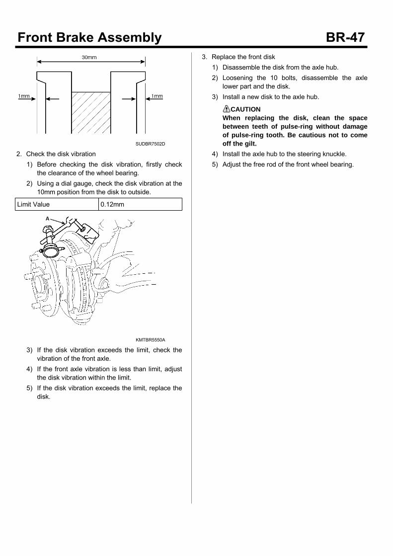
SUDBR7502D
2. Check the disk vibration1) Before checking the disk vibration, firstly check
the clearance of the wheel bearing.2) Using a dial gauge, check the disk vibration at the
10mm position from the disk to outside.
Limit Value 0.12mm
KMTBR5550A
3) If the disk vibration exceeds the limit, check thevibration of the front axle.
4) If the front axle vibration is less than limit, adjustthe disk vibration within the limit.
5) If the disk vibration exceeds the limit, replace thedisk.
3. Replace the front disk1) Disassemble the disk from the axle hub.2) Loosening the 10 bolts, disassemble the axle
lower part and the disk.3) Install a new disk to the axle hub.
CAUTIONWhen replacing the disk, clean the spacebetween teeth of pulse-ring without damageof pulse-ring tooth. Be cautious not to comeoff the gilt.
4) Install the axle hub to the steering knuckle.5) Adjust the free rod of the front wheel bearing.
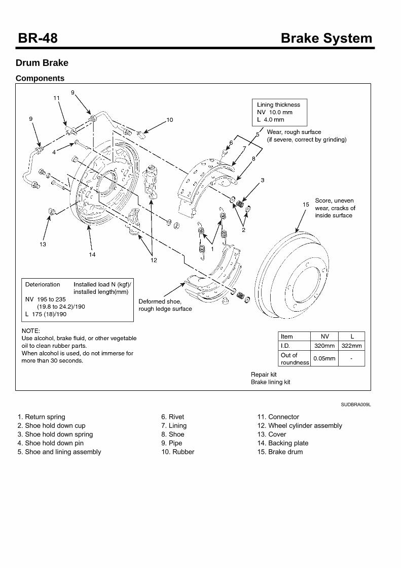
Drum BrakeComponents
SUDBRA009L
1. Return spring2. Shoe hold down cup3. Shoe hold down spring4. Shoe hold down pin5. Shoe and lining assembly
6. Rivet7. Lining8. Shoe9. Pipe10. Rubber
11. Connector12. Wheel cylinder assembly13. Cover14. Backing plate15. Brake drum
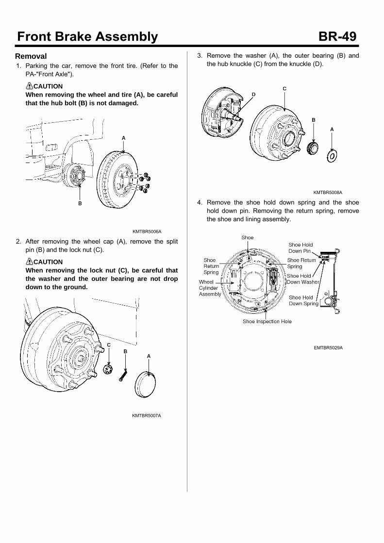
Removal1. Parking the car, remove the front tire. (Refer to thePA-"Front Axle").
CAUTIONWhen removing the wheel and tire (A), be carefulthat the hub bolt (B) is not damaged.
KMTBR5006A
2. After removing the wheel cap (A), remove the splitpin (B) and the lock nut (C).
CAUTIONWhen removing the lock nut (C), be careful thatthe washer and the outer bearing are not dropdown to the ground.
KMTBR5007A
3. Remove the washer (A), the outer bearing (B) andthe hub knuckle (C) from the knuckle (D).
KMTBR5008A
4. Remove the shoe hold down spring and the shoehold down pin. Removing the return spring, removethe shoe and lining assembly.
EMTBR5029A
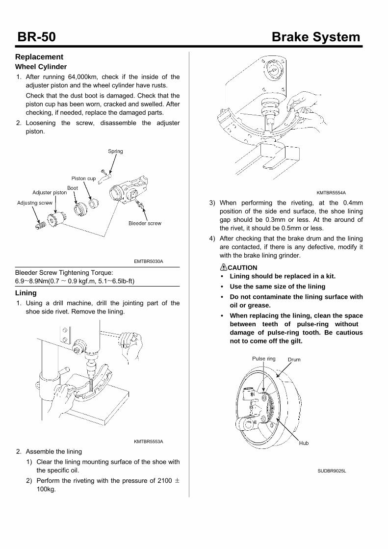
ReplacementWheel Cylinder1. After running 64,000km, check if the inside of theadjuster piston and the wheel cylinder have rusts.Check that the dust boot is damaged. Check that thepiston cup has been worn, cracked and swelled. Afterchecking, if needed, replace the damaged parts.
2. Loosening the screw, disassemble the adjusterpiston.
EMTBR5030A
Bleeder Screw Tightening Torque:6.9~8.9Nm(0.7 ~ 0.9 kgf.m, 5.1~6.5lb-ft)
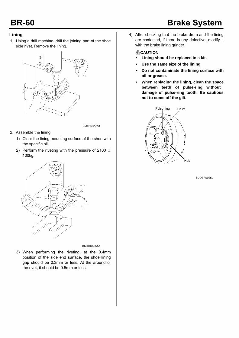
Lining1. Using a drill machine, drill the jointing part of theshoe side rivet. Remove the lining.
KMTBR5553A
2. Assemble the lining1) Clear the lining mounting surface of the shoe with
the specific oil.2) Perform the riveting with the pressure of 2100 ±
100kg.
KMTBR5554A
3) When performing the riveting, at the 0.4mmposition of the side end surface, the shoe lininggap should be 0.3mm or less. At the around ofthe rivet, it should be 0.5mm or less.
4) After checking that the brake drum and the liningare contacted, if there is any defective, modify itwith the brake lining grinder.
CAUTION• Lining should be replaced in a kit.• Use the same size of the lining• Do not contaminate the lining surface with
oil or grease.• When replacing the lining, clean the space
between teeth of pulse-ring withoutdamage of pulse-ring tooth. Be cautiousnot to come off the gilt.
SUDBR9025L
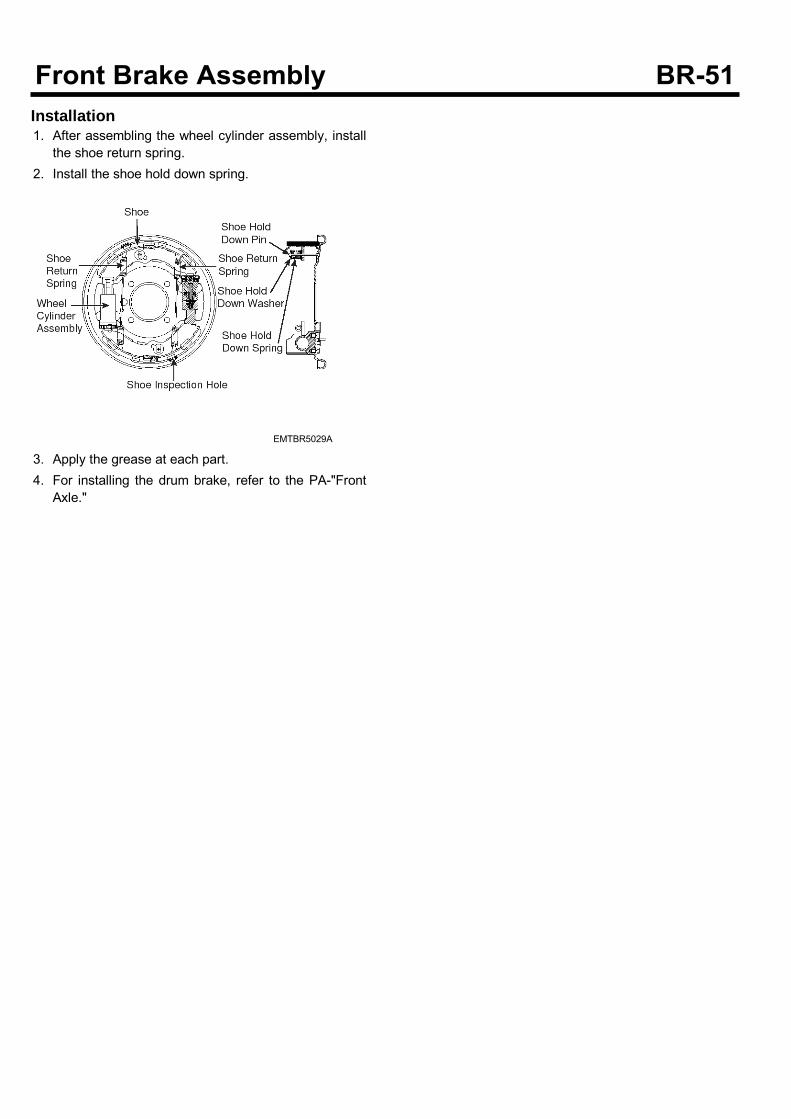
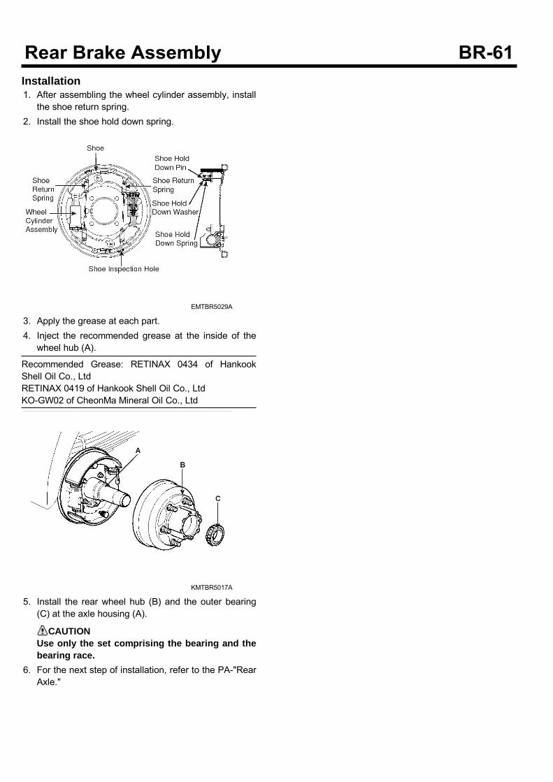
Installation1. After assembling the wheel cylinder assembly, installthe shoe return spring.
2. Install the shoe hold down spring.
EMTBR5029A
3. Apply the grease at each part.4. For installing the drum brake, refer to the PA-"FrontAxle."
Parking Brake SystemComponents
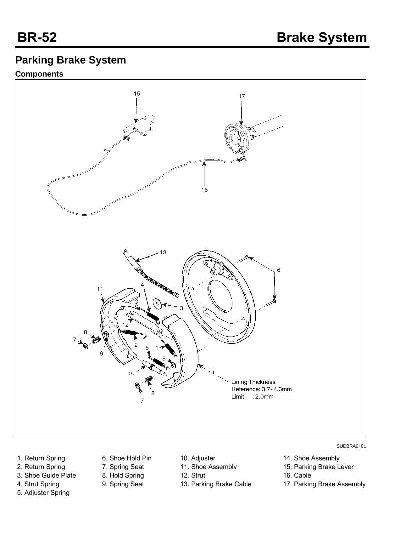
SUDBRA010L
1. Return Spring2. Return Spring3. Shoe Guide Plate4. Strut Spring5. Adjuster Spring
6. Shoe Hold Pin7. Spring Seat8. Hold Spring9. Spring Seat
10. Adjuster11. Shoe Assembly12. Strut13. Parking Brake Cable
14. Shoe Assembly15. Parking Brake Lever16. Cable17. Parking Brake Assembly
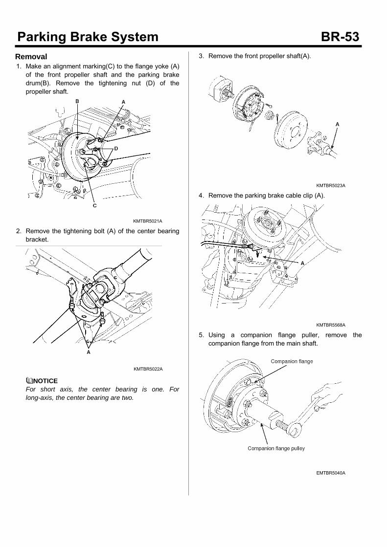
Removal1. Make an alignment marking(C) to the flange yoke (A)of the front propeller shaft and the parking brakedrum(B). Remove the tightening nut (D) of thepropeller shaft.
KMTBR5021A
2. Remove the tightening bolt (A) of the center bearingbracket.
KMTBR5022A
NOTICEFor short axis, the center bearing is one. Forlong-axis, the center bearing are two.
3. Remove the front propeller shaft(A).
KMTBR5023A
4. Remove the parking brake cable clip (A).
KMTBR5568A
5. Using a companion flange puller, remove thecompanion flange from the main shaft.
EMTBR5040A
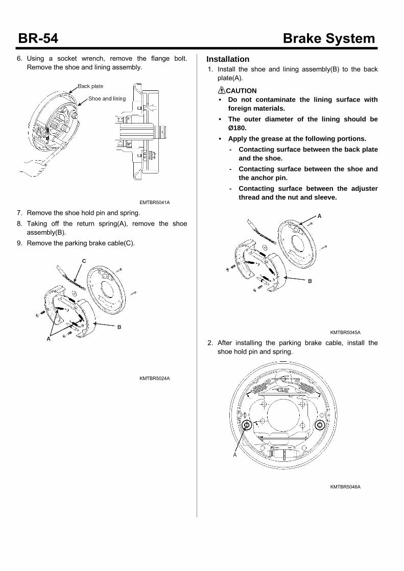
6. Using a socket wrench, remove the flange bolt.Remove the shoe and lining assembly.
EMTBR5041A
7. Remove the shoe hold pin and spring.8. Taking off the return spring(A), remove the shoeassembly(B).
9. Remove the parking brake cable(C).
KMTBR5024A
Installation1. Install the shoe and lining assembly(B) to the backplate(A).
CAUTION• Do not contaminate the lining surface with
foreign materials.• The outer diameter of the lining should be
Ø180.• Apply the grease at the following portions.
- Contacting surface between the back plateand the shoe.
- Contacting surface between the shoe andthe anchor pin.
- Contacting surface between the adjusterthread and the nut and sleeve.
KMTBR5045A
2. After installing the parking brake cable, install theshoe hold pin and spring.
KMTBR5046A

3. Aligning the align markings(C) of the rear axlecompanion flange (A) and the flange yoke (B) of therear propeller shaft, install the tightening bolt (D) ofthe propeller shaft.
Tightening Torque :98~117 Nm(10~12 kgf.m, 72.3~86.7 lb-ft) : P359~69 Nm(6~7 kgf.m, 43.3~50.6 lb-ft) : P2
KMTBR5025A
4. Install the tightening bolt (A) of the center bearingbracket.
Tightening Torque :69~93 Nm(7.0~9.5 kgf.m, 50.6~68.7 lb-ft)
KMTBR5022A
NOTICEFor short-axis, the center bearing is none. Forlong-axis, the center bearing is one.
5. Aligning the align marking (C) of the flange yoke (A)of the front propeller shaft and that of the parkingbrake drum (B), install the tightening nut (D) of thepropeller shaft.
Tightening Torque :98~117 Nm(10~12 kgf.m, 72.3~86.7 lb-ft)
KMTBR5021A
6. Inject the recommended grease to the grease nipple(A) until the grease is leaked out oil seal. Clear theleaked grease.
Recommended Grease: ALVANIA EP#2
KMTBR5026A
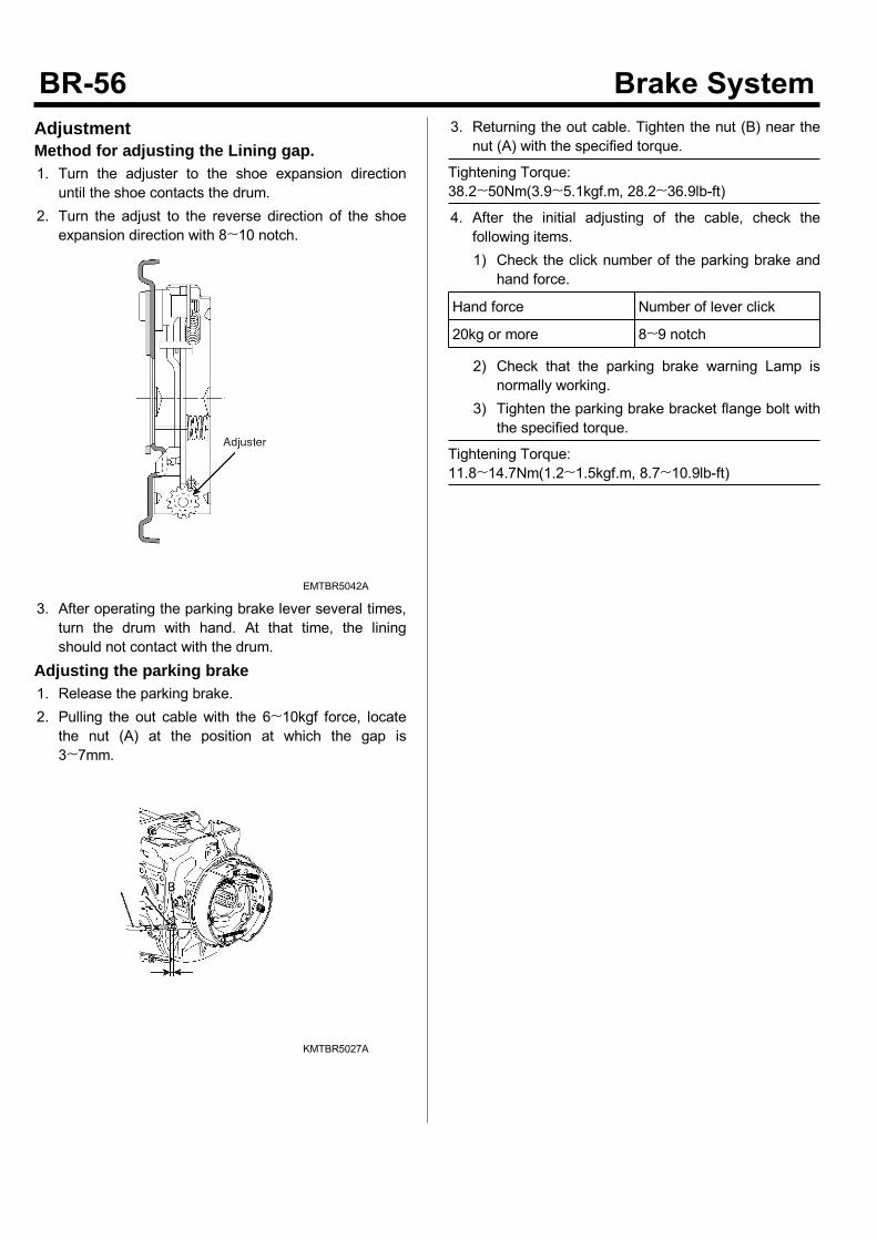
AdjustmentMethod for adjusting the Lining gap.1. Turn the adjuster to the shoe expansion directionuntil the shoe contacts the drum.
2. Turn the adjust to the reverse direction of the shoeexpansion direction with 8~10 notch.
EMTBR5042A
3. After operating the parking brake lever several times,turn the drum with hand. At that time, the liningshould not contact with the drum.
Adjusting the parking brake1. Release the parking brake.2. Pulling the out cable with the 6~10kgf force, locatethe nut (A) at the position at which the gap is3~7mm.
KMTBR5027A
3. Returning the out cable. Tighten the nut (B) near thenut (A) with the specified torque.
Tightening Torque:38.2~50Nm(3.9~5.1kgf.m, 28.2~36.9lb-ft)
4. After the initial adjusting of the cable, check thefollowing items.1) Check the click number of the parking brake and
hand force.
Hand force Number of lever click
20kg or more 8~9 notch
2) Check that the parking brake warning Lamp isnormally working.
3) Tighten the parking brake bracket flange bolt withthe specified torque.
Tightening Torque:11.8~14.7Nm(1.2~1.5kgf.m, 8.7~10.9lb-ft)
Rear Brake AssemblyDrum BrakeComponents
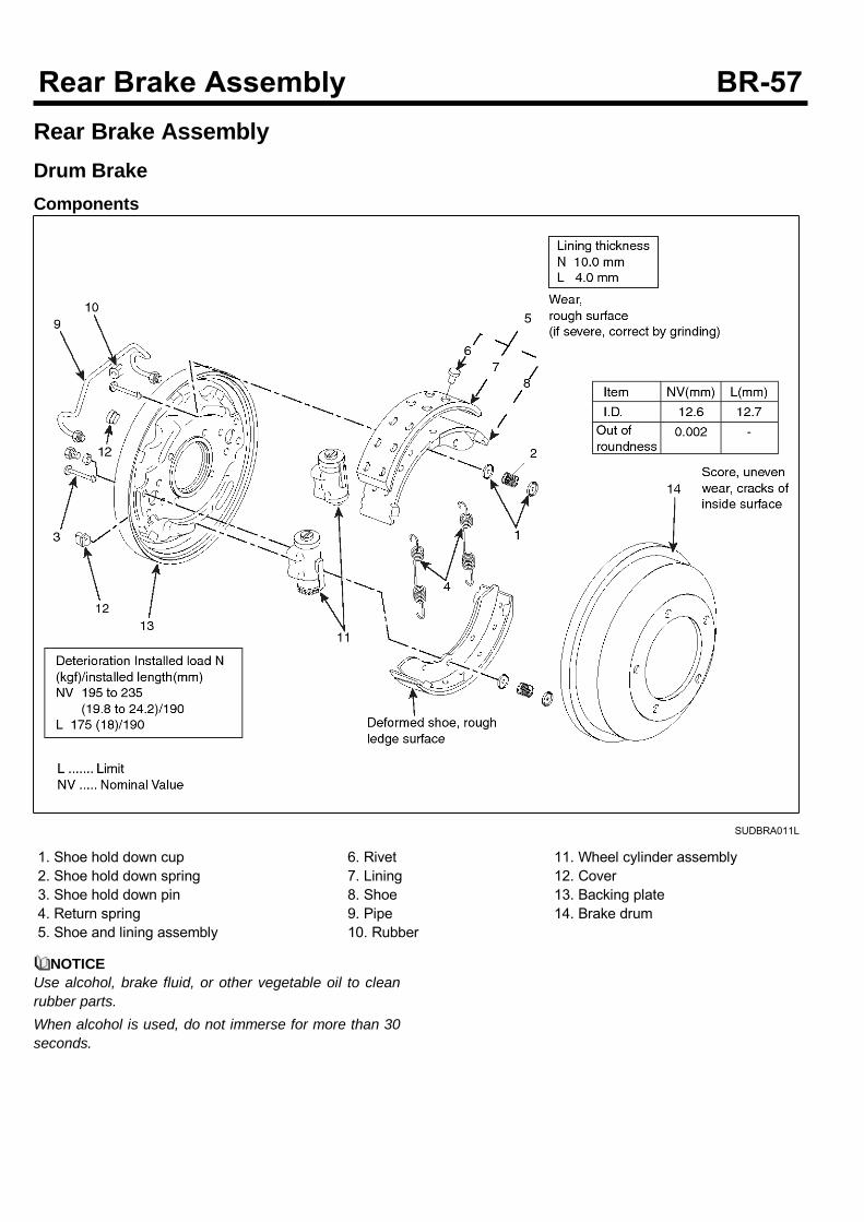
SUDBRA011L
1. Shoe hold down cup2. Shoe hold down spring3. Shoe hold down pin4. Return spring5. Shoe and lining assembly
6. Rivet7. Lining8. Shoe9. Pipe10. Rubber
11. Wheel cylinder assembly12. Cover13. Backing plate14. Brake drum
NOTICEUse alcohol, brake fluid, or other vegetable oil to cleanrubber parts.When alcohol is used, do not immerse for more than 30seconds.
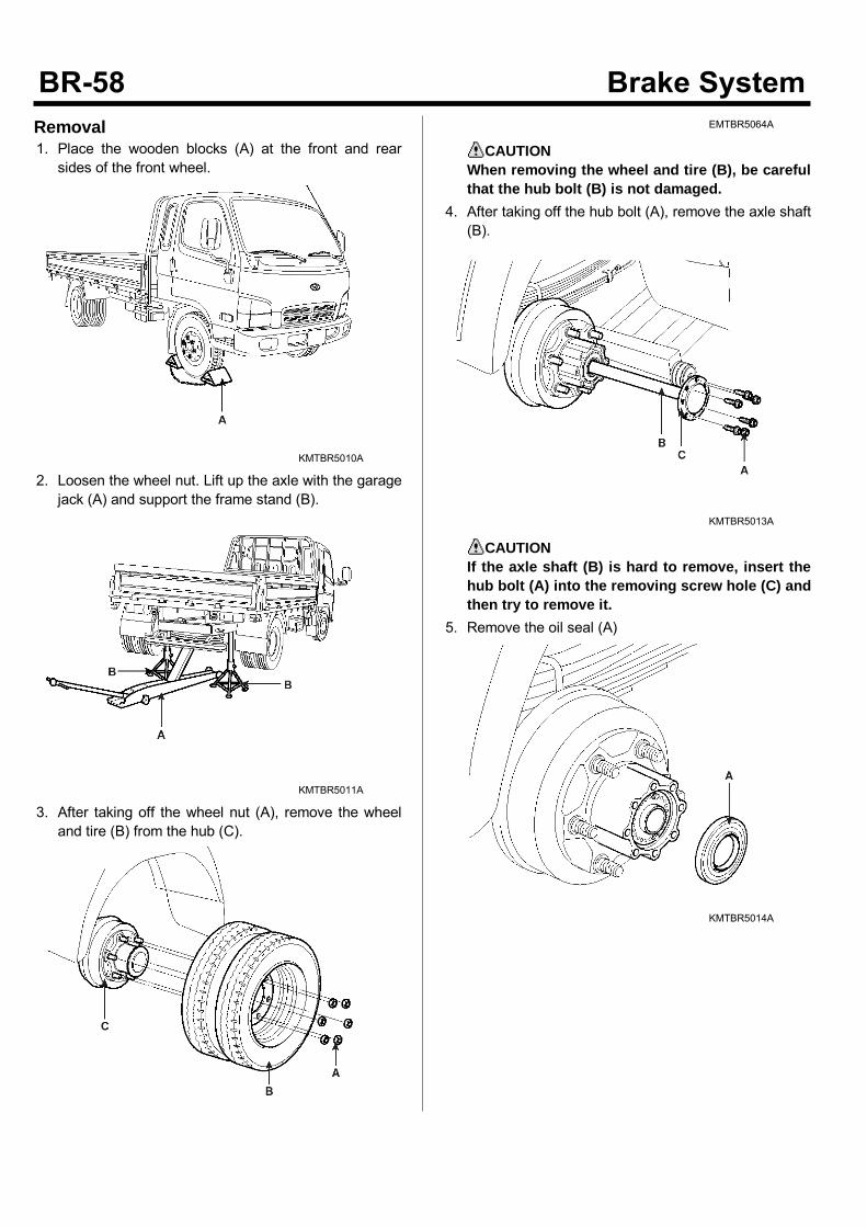
Removal1. Place the wooden blocks (A) at the front and rearsides of the front wheel.
KMTBR5010A
2. Loosen the wheel nut. Lift up the axle with the garagejack (A) and support the frame stand (B).
KMTBR5011A
3. After taking off the wheel nut (A), remove the wheeland tire (B) from the hub (C).
EMTBR5064A
CAUTIONWhen removing the wheel and tire (B), be carefulthat the hub bolt (B) is not damaged.
4. After taking off the hub bolt (A), remove the axle shaft(B).
KMTBR5013A
CAUTIONIf the axle shaft (B) is hard to remove, insert thehub bolt (A) into the removing screw hole (C) andthen try to remove it.
5. Remove the oil seal (A)
KMTBR5014A
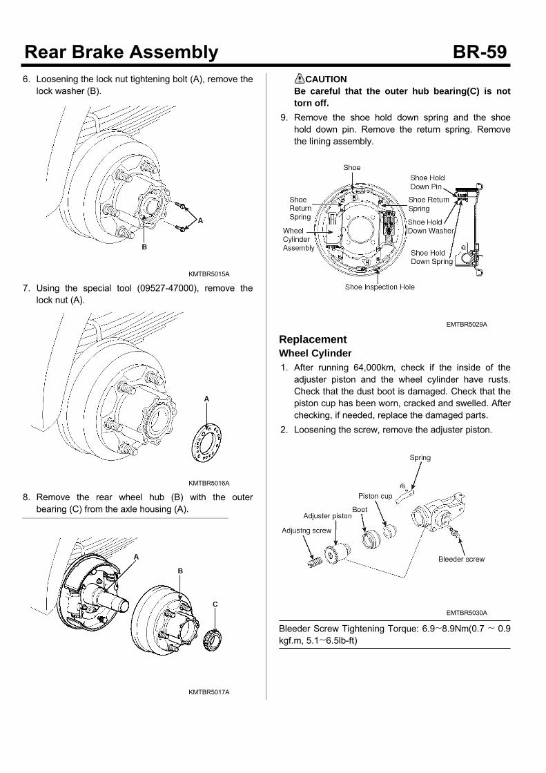
6. Loosening the lock nut tightening bolt (A), remove thelock washer (B).
KMTBR5015A
7. Using the special tool (09527-47000), remove thelock nut (A).
KMTBR5016A
8. Remove the rear wheel hub (B) with the outerbearing (C) from the axle housing (A).
KMTBR5017A
CAUTIONBe careful that the outer hub bearing(C) is nottorn off.
9. Remove the shoe hold down spring and the shoehold down pin. Remove the return spring. Removethe lining assembly.
EMTBR5029A
ReplacementWheel Cylinder1. After running 64,000km, check if the inside of theadjuster piston and the wheel cylinder have rusts.Check that the dust boot is damaged. Check that thepiston cup has been worn, cracked and swelled. Afterchecking, if needed, replace the damaged parts.
2. Loosening the screw, remove the adjuster piston.
EMTBR5030A
Bleeder Screw Tightening Torque: 6.9~8.9Nm(0.7 ~ 0.9kgf.m, 5.1~6.5lb-ft)
Lining1. Using a drill machine, drill the joining part of the shoeside rivet. Remove the lining.
KMTBR5553A
2. Assemble the lining1) Clear the lining mounting surface of the shoe with
the specific oil.2) Perform the riveting with the pressure of 2100 ±
100kg.
KMTBR5554A
3) When performing the riveting, at the 0.4mmposition of the side end surface, the shoe lininggap should be 0.3mm or less. At the around ofthe rivet, it should be 0.5mm or less.
4) After checking that the brake drum and the liningare contacted, if there is any defective, modify itwith the brake lining grinder.
CAUTION• Lining should be replaced in a kit.• Use the same size of the lining• Do not contaminate the lining surface with
oil or grease.• When replacing the lining, clean the space
between teeth of pulse-ring withoutdamage of pulse-ring tooth. Be cautiousnot to come off the gilt.
SUDBR9025L
Installation1. After assembling the wheel cylinder assembly, installthe shoe return spring.
2. Install the shoe hold down spring.
EMTBR5029A
3. Apply the grease at each part.4. Inject the recommended grease at the inside of thewheel hub (A).
Recommended Grease: RETINAX 0434 of HankookShell Oil Co., LtdRETINAX 0419 of Hankook Shell Oil Co., LtdKO-GW02 of CheonMa Mineral Oil Co., Ltd
KMTBR5017A
5. Install the rear wheel hub (B) and the outer bearing(C) at the axle housing (A).
CAUTIONUse only the set comprising the bearing and thebearing race.
6. For the next step of installation, refer to the PA-"RearAxle."
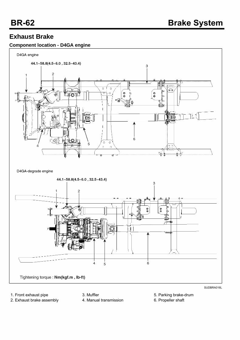
Exhaust BrakeComponent location - D4GA engine
SUDBRA016L
1. Front exhaust pipe2. Exhaust brake assembly
3. Muffler4. Manual transmission
5. Parking brake-drum6. Propeller shaft
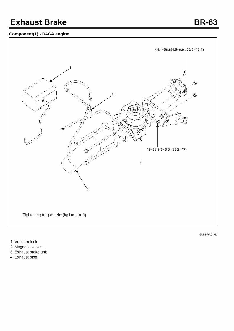
Component(1) - D4GA engine
SUDBRA017L
1. Vacuum tank2. Magnetic valve3. Exhaust brake unit4. Exhaust pipe
Component(2) - D4GA engine
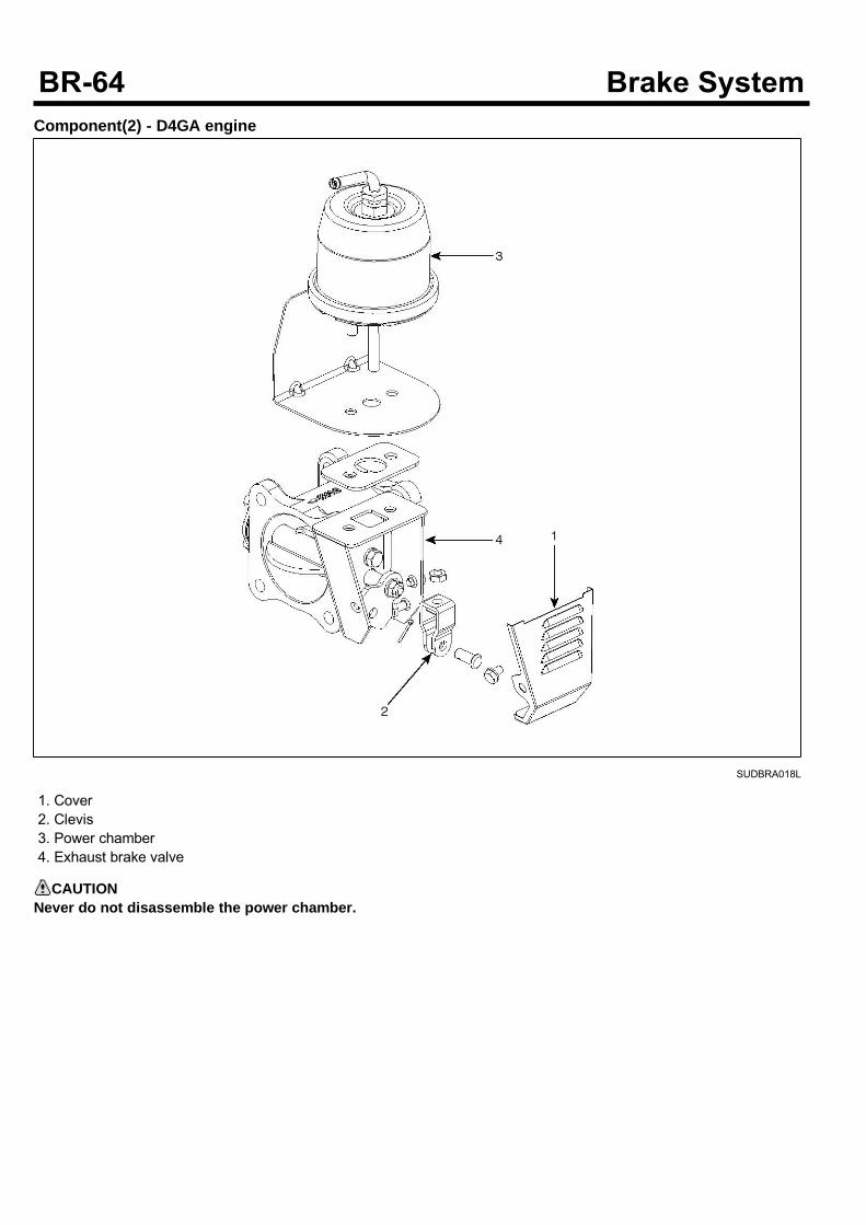
SUDBRA018L
1. Cover2. Clevis3. Power chamber4. Exhaust brake valve
CAUTIONNever do not disassemble the power chamber.
Component (1) - Except D4GA engine
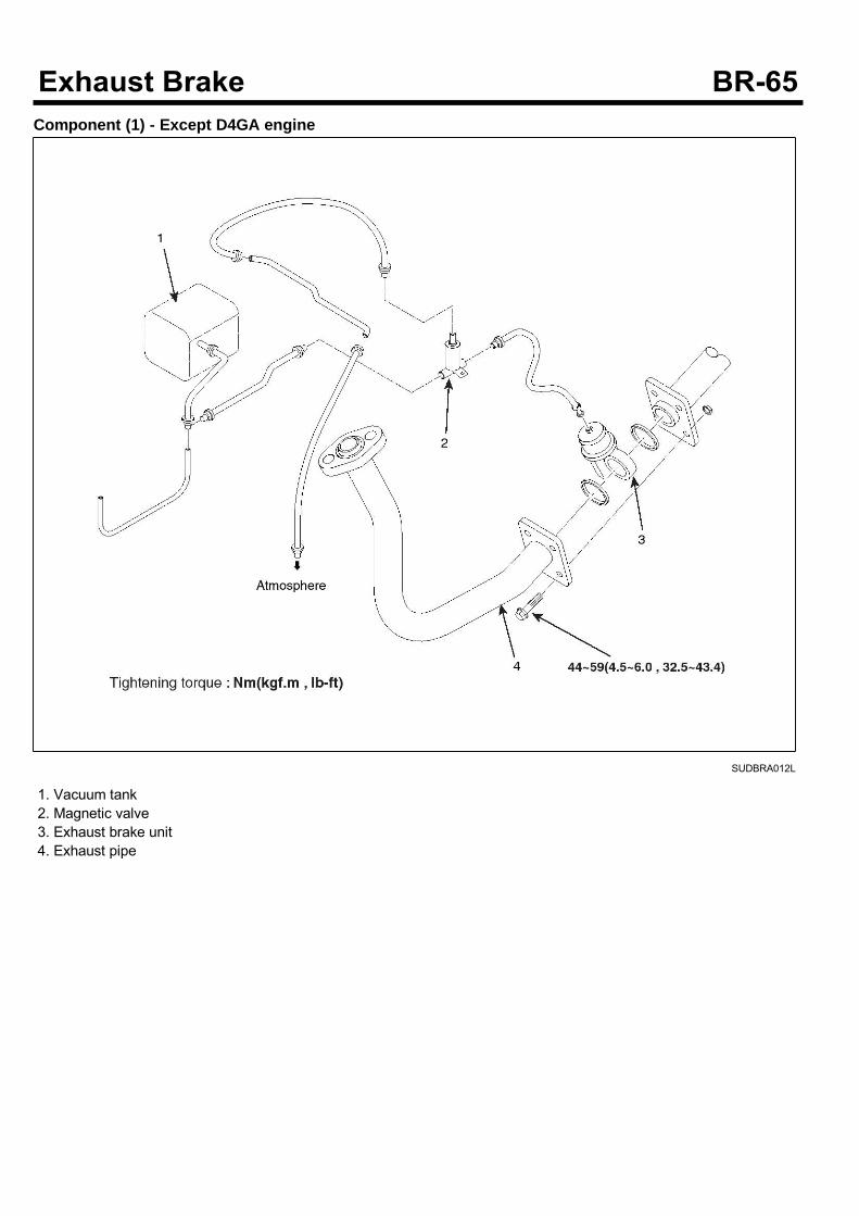
SUDBRA012L
1. Vacuum tank2. Magnetic valve3. Exhaust brake unit4. Exhaust pipe
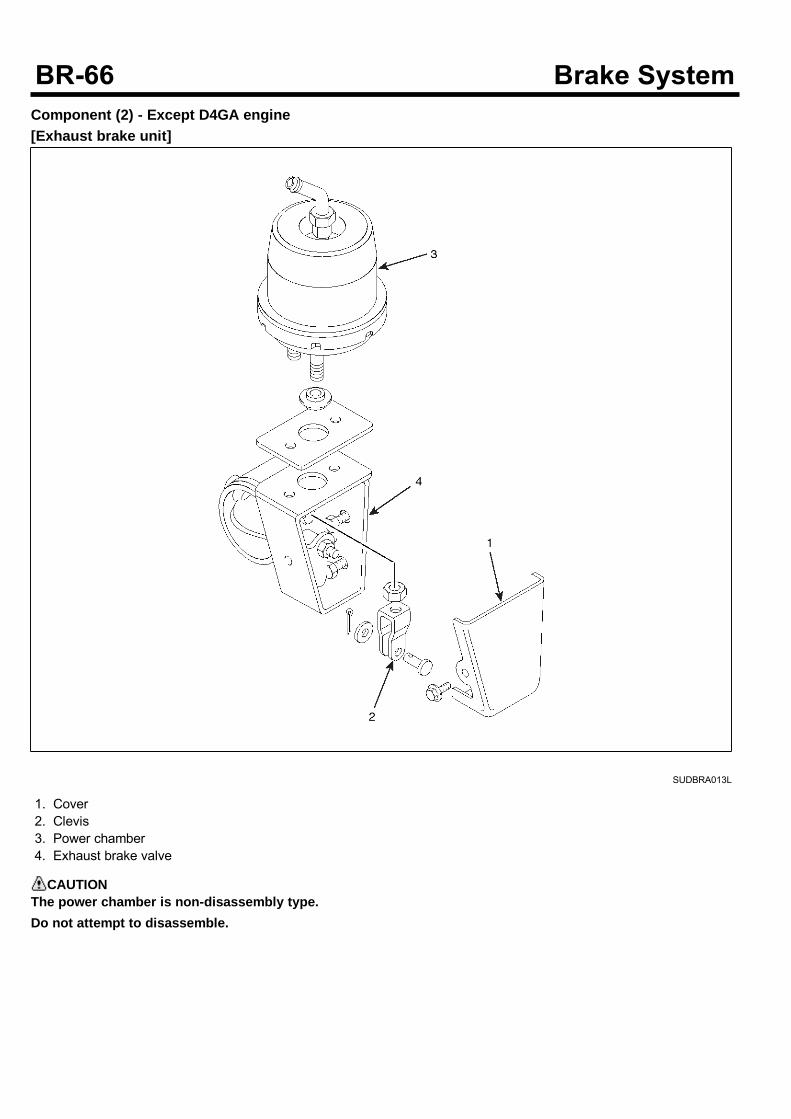
Component (2) - Except D4GA engine[Exhaust brake unit]
SUDBRA013L
1. Cover2. Clevis3. Power chamber4. Exhaust brake valve
CAUTIONThe power chamber is non-disassembly type.Do not attempt to disassemble.
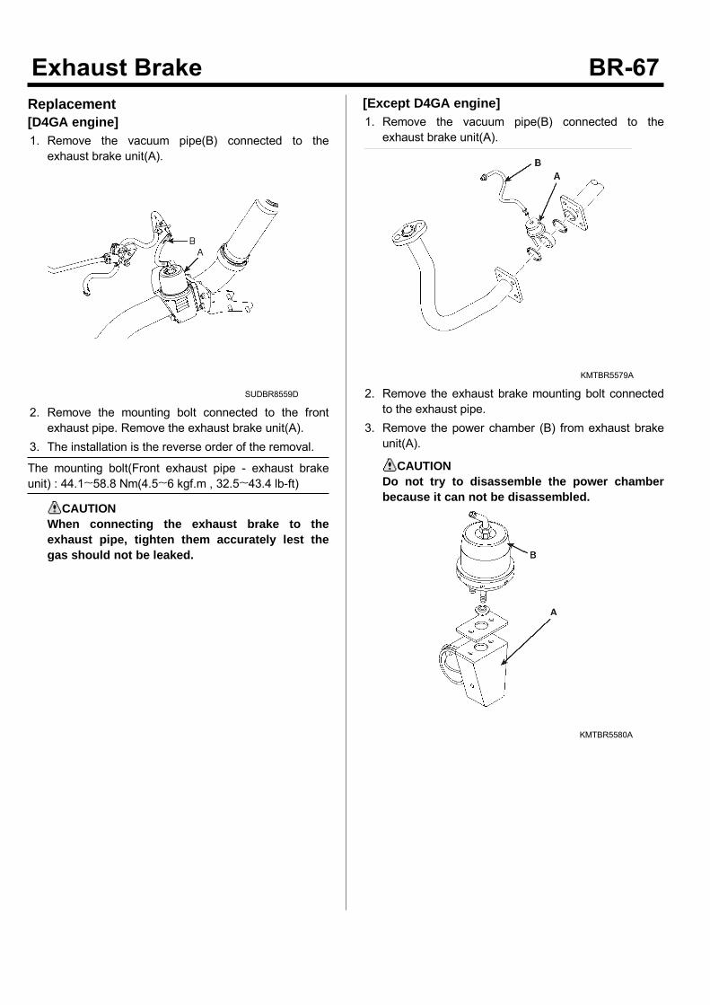
Replacement[D4GA engine]1. Remove the vacuum pipe(B) connected to theexhaust brake unit(A).
SUDBR8559D
2. Remove the mounting bolt connected to the frontexhaust pipe. Remove the exhaust brake unit(A).
3. The installation is the reverse order of the removal.
The mounting bolt(Front exhaust pipe - exhaust brakeunit) : 44.1~58.8 Nm(4.5~6 kgf.m , 32.5~43.4 lb-ft)
CAUTIONWhen connecting the exhaust brake to theexhaust pipe, tighten them accurately lest thegas should not be leaked.
[Except D4GA engine]1. Remove the vacuum pipe(B) connected to theexhaust brake unit(A).
KMTBR5579A
2. Remove the exhaust brake mounting bolt connectedto the exhaust pipe.
3. Remove the power chamber (B) from exhaust brakeunit(A).
CAUTIONDo not try to disassemble the power chamberbecause it can not be disassembled.
KMTBR5580A
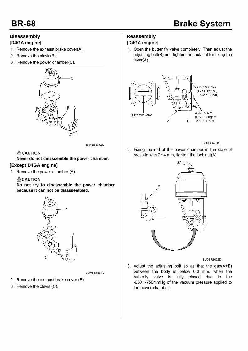
Disassembly[D4GA engine]1. Remove the exhaust brake cover(A).2. Remove the clevis(B).3. Remove the power chamber(C).
SUDBR8026D
CAUTIONNever do not disassemble the power chamber.
[Except D4GA engine]1. Remove the power chamber (A).
CAUTIONDo not try to disassemble the power chamberbecause it can not be disassembled.
KMTBR5581A
2. Remove the exhaust brake cover (B).3. Remove the clevis (C).
Reassembly[D4GA engine]1. Open the butter fly valve completely. Then adjust theadjusting bolt(B) and tighten the lock nut for fixing thelever(A).
SUDBRA019L
2. Fixing the rod of the power chamber in the state ofpress-in with 2~4 mm, tighten the lock nut(A).
SUDBR8028D
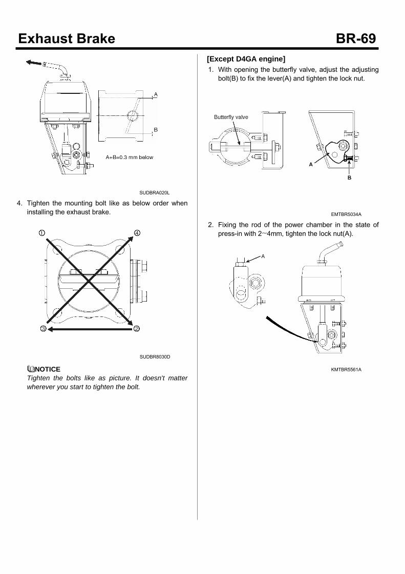
3. Adjust the adjusting bolt so as that the gap(A+B)between the body is below 0.3 mm, when thebutterfly valve is fully closed due to the-650~-750mmHg of the vacuum pressure applied tothe power chamber.
SUDBRA020L
4. Tighten the mounting bolt like as below order wheninstalling the exhaust brake.
SUDBR8030D
NOTICETighten the bolts like as picture. It doesn't matterwherever you start to tighten the bolt.
[Except D4GA engine]1. With opening the butterfly valve, adjust the adjustingbolt(B) to fix the lever(A) and tighten the lock nut.
EMTBR5034A
2. Fixing the rod of the power chamber in the state ofpress-in with 2~4mm, tighten the lock nut(A).
KMTBR5561A
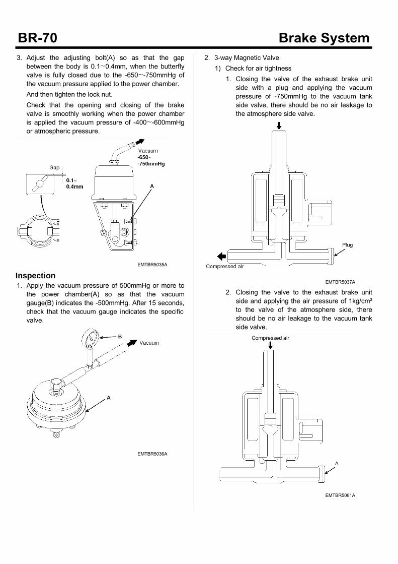
3. Adjust the adjusting bolt(A) so as that the gapbetween the body is 0.1~0.4mm, when the butterflyvalve is fully closed due to the -650~-750mmHg ofthe vacuum pressure applied to the power chamber.And then tighten the lock nut.Check that the opening and closing of the brakevalve is smoothly working when the power chamberis applied the vacuum pressure of -400~-600mmHgor atmospheric pressure.
EMTBR5035A
Inspection1. Apply the vacuum pressure of 500mmHg or more tothe power chamber(A) so as that the vacuumgauge(B) indicates the -500mmHg. After 15 seconds,check that the vacuum gauge indicates the specificvalve.
EMTBR5036A
2. 3-way Magnetic Valve1) Check for air tightness
1. Closing the valve of the exhaust brake unitside with a plug and applying the vacuumpressure of -750mmHg to the vacuum tankside valve, there should be no air leakage tothe atmosphere side valve.
EMTBR5037A
2. Closing the valve to the exhaust brake unitside and applying the air pressure of 1kg/cm²to the valve of the atmosphere side, thereshould be no air leakage to the vacuum tankside valve.
EMTBR5061A
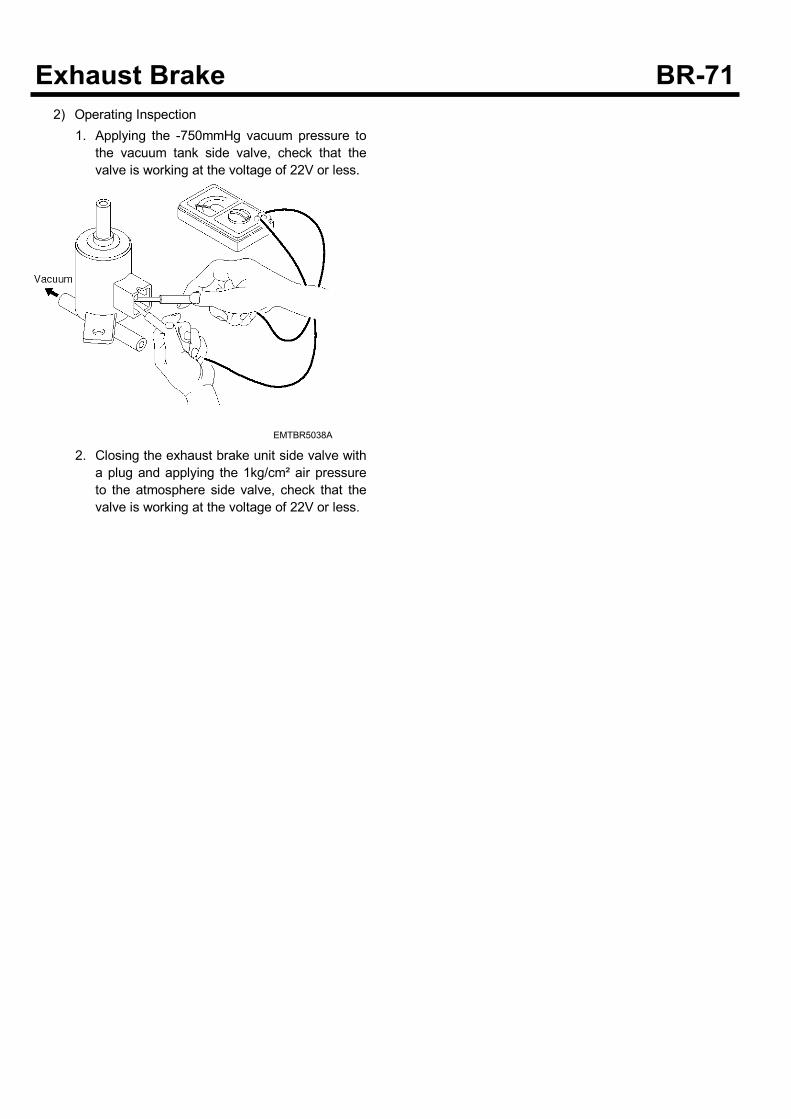
2) Operating Inspection1. Applying the -750mmHg vacuum pressure to
the vacuum tank side valve, check that thevalve is working at the voltage of 22V or less.
EMTBR5038A
2. Closing the exhaust brake unit side valve witha plug and applying the 1kg/cm² air pressureto the atmosphere side valve, check that thevalve is working at the voltage of 22V or less.
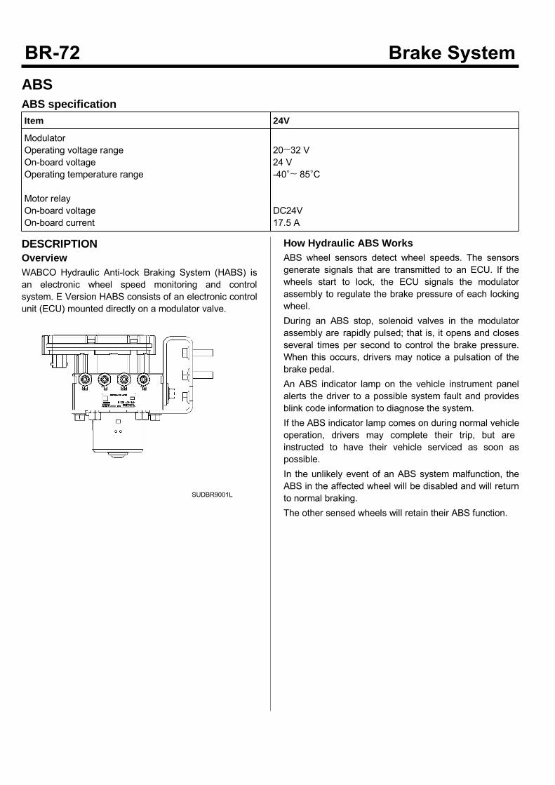
ABSABS specificationItem 24V
ModulatorOperating voltage rangeOn-board voltageOperating temperature range
Motor relayOn-board voltageOn-board current
20~32 V24 V-40°~ 85°C
DC24V17.5 A
DESCRIPTIONOverviewWABCO Hydraulic Anti-lock Braking System (HABS) isan electronic wheel speed monitoring and controlsystem. E Version HABS consists of an electronic controlunit (ECU) mounted directly on a modulator valve.
SUDBR9001L
How Hydraulic ABS WorksABS wheel sensors detect wheel speeds. The sensorsgenerate signals that are transmitted to an ECU. If thewheels start to lock, the ECU signals the modulatorassembly to regulate the brake pressure of each lockingwheel.During an ABS stop, solenoid valves in the modulatorassembly are rapidly pulsed; that is, it opens and closesseveral times per second to control the brake pressure.When this occurs, drivers may notice a pulsation of thebrake pedal.An ABS indicator lamp on the vehicle instrument panelalerts the driver to a possible system fault and providesblink code information to diagnose the system.If the ABS indicator lamp comes on during normal vehicleoperation, drivers may complete their trip, but areinstructed to have their vehicle serviced as soon aspossible.In the unlikely event of an ABS system malfunction, theABS in the affected wheel will be disabled and will returnto normal braking.The other sensed wheels will retain their ABS function.
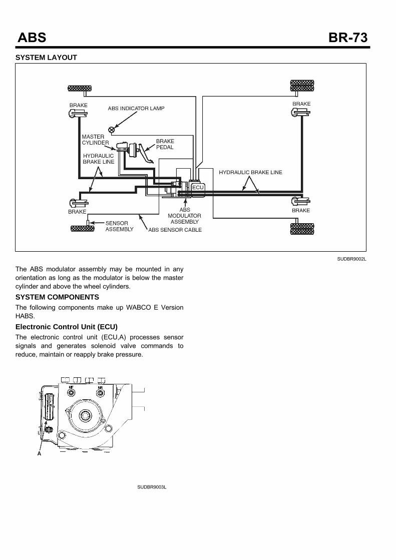
SYSTEM LAYOUT
SUDBR9002L
The ABS modulator assembly may be mounted in anyorientation as long as the modulator is below the mastercylinder and above the wheel cylinders.SYSTEM COMPONENTSThe following components make up WABCO E VersionHABS.Electronic Control Unit (ECU)The electronic control unit (ECU,A) processes sensorsignals and generates solenoid valve commands toreduce, maintain or reapply brake pressure.
SUDBR9003L
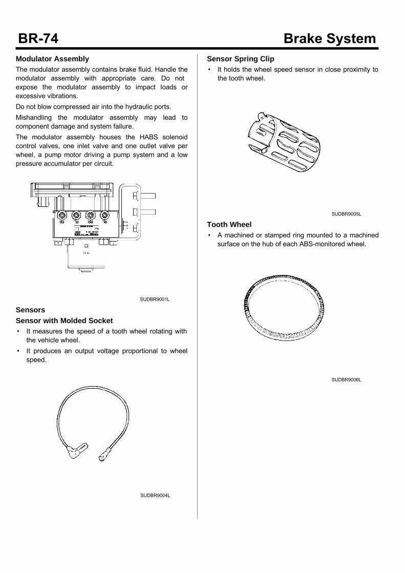
Modulator AssemblyThe modulator assembly contains brake fluid. Handle themodulator assembly with appropriate care. Do notexpose the modulator assembly to impact loads orexcessive vibrations.Do not blow compressed air into the hydraulic ports.Mishandling the modulator assembly may lead tocomponent damage and system failure.The modulator assembly houses the HABS solenoidcontrol valves, one inlet valve and one outlet valve perwheel, a pump motor driving a pump system and a lowpressure accumulator per circuit.
SUDBR9001L
SensorsSensor with Molded Socket• It measures the speed of a tooth wheel rotating withthe vehicle wheel.
• It produces an output voltage proportional to wheelspeed.
SUDBR9004L
Sensor Spring Clip• It holds the wheel speed sensor in close proximity tothe tooth wheel.
SUDBR9005L
Tooth Wheel• A machined or stamped ring mounted to a machinedsurface on the hub of each ABS-monitored wheel.
SUDBR9006L
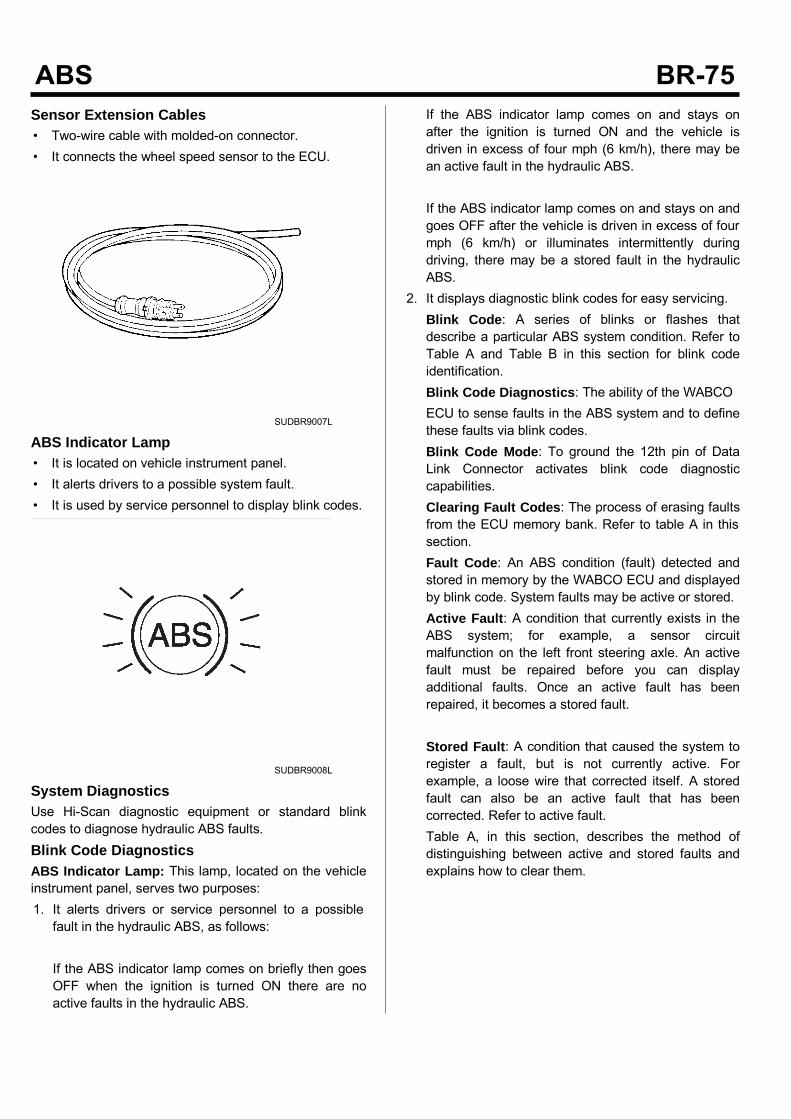
Sensor Extension Cables• Two-wire cable with molded-on connector.• It connects the wheel speed sensor to the ECU.
SUDBR9007L
ABS Indicator Lamp• It is located on vehicle instrument panel.• It alerts drivers to a possible system fault.• It is used by service personnel to display blink codes.
SUDBR9008L
System DiagnosticsUse Hi-Scan diagnostic equipment or standard blinkcodes to diagnose hydraulic ABS faults.Blink Code DiagnosticsABS Indicator Lamp: This lamp, located on the vehicleinstrument panel, serves two purposes:1. It alerts drivers or service personnel to a possiblefault in the hydraulic ABS, as follows:
If the ABS indicator lamp comes on briefly then goesOFF when the ignition is turned ON there are noactive faults in the hydraulic ABS.
If the ABS indicator lamp comes on and stays onafter the ignition is turned ON and the vehicle isdriven in excess of four mph (6 km/h), there may bean active fault in the hydraulic ABS.
If the ABS indicator lamp comes on and stays on andgoes OFF after the vehicle is driven in excess of fourmph (6 km/h) or illuminates intermittently duringdriving, there may be a stored fault in the hydraulicABS.
2. It displays diagnostic blink codes for easy servicing.Blink Code: A series of blinks or flashes thatdescribe a particular ABS system condition. Refer toTable A and Table B in this section for blink codeidentification.Blink Code Diagnostics: The ability of the WABCOECU to sense faults in the ABS system and to definethese faults via blink codes.Blink Code Mode: To ground the 12th pin of DataLink Connector activates blink code diagnosticcapabilities.Clearing Fault Codes: The process of erasing faultsfrom the ECU memory bank. Refer to table A in thissection.Fault Code: An ABS condition (fault) detected andstored in memory by the WABCO ECU and displayedby blink code. System faults may be active or stored.Active Fault: A condition that currently exists in theABS system; for example, a sensor circuitmalfunction on the left front steering axle. An activefault must be repaired before you can displayadditional faults. Once an active fault has beenrepaired, it becomes a stored fault.
Stored Fault: A condition that caused the system toregister a fault, but is not currently active. Forexample, a loose wire that corrected itself. A storedfault can also be an active fault that has beencorrected. Refer to active fault.Table A, in this section, describes the method ofdistinguishing between active and stored faults andexplains how to clear them.
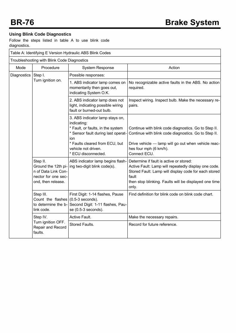
Using Blink Code DiagnosticsFollow the steps listed in table A to use blink codediagnostics.
Table A: Identifying E Version Hydraulic ABS Blink Codes
Troubleshooting with Blink Code Diagnostics
Mode Procedure System Response Action
Diagnostics Step I.Turn ignition on.
Possible responses:
1. ABS indicator lamp comes onmomentarily then goes out,indicating System O.K.
No recognizable active faults in the ABS. No actionrequired.
2. ABS indicator lamp does notlight, indicating possible wiringfault or burned-out bulb.
Inspect wiring. Inspect bulb. Make the necessary re-pairs.
3. ABS indicator lamp stays on,indicating:* Fault, or faults, in the system* Sensor fault during last operat-ion* Faults cleared from ECU, butvehicle not driven.* ECU disconnected.
Continue with blink code diagnostics. Go to Step II.Continue with blink code diagnostics. Go to Step II.
Drive vehicle — lamp will go out when vehicle reac-hes four mph (6 km/h).Connect ECU.
Step II.Ground the 12th pi-n of Data Link Con-nector for one sec-ond, then release.
ABS indicator lamp begins flash-ing two-digit blink code(s).
Determine if fault is active or stored:Active Fault: Lamp will repeatedly display one code.Stored Fault: Lamp will display code for each storedfaultthen stop blinking. Faults will be displayed one timeonly.
Step III.Count the flashesto determine the b-link code.
First Digit: 1-14 flashes, Pause(0.5-3 seconds).Second Digit: 1-11 flashes, Pau-se (0.5-3 seconds).
Find definition for blink code on blink code chart.
Step IV.Turn ignition OFF.Repair and Recordfaults.
Active Fault. Make the necessary repairs.
Stored Faults. Record for future reference.
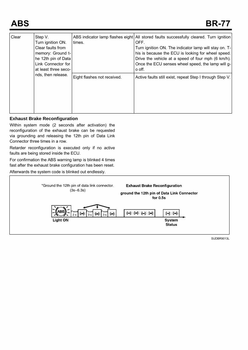
Clear Step V.Turn ignition ON.Clear faults frommemory: Ground t-he 12th pin of DataLink Connector forat least three seco-nds, then release.
ABS indicator lamp flashes eighttimes.
All stored faults successfully cleared. Turn ignitionOFF.Turn ignition ON. The indicator lamp will stay on. T-his is because the ECU is looking for wheel speed.Drive the vehicle at a speed of four mph (6 km/h).Once the ECU senses wheel speed, the lamp will g-o off.
Eight flashes not received. Active faults still exist, repeat Step I through Step V.
Exhaust Brake ReconfigurationWithin system mode (2 seconds after activation) thereconfiguration of the exhaust brake can be requestedvia grounding and releasing the 12th pin of Data LinkConnector three times in a row.Retarder reconfiguration is executed only if no activefaults are being stored inside the ECU.For confirmation the ABS warning lamp is blinked 4 timesfast after the exhaust brake configuration has been reset.Afterwards the system code is blinked out endlessly.
SUDBR9013L
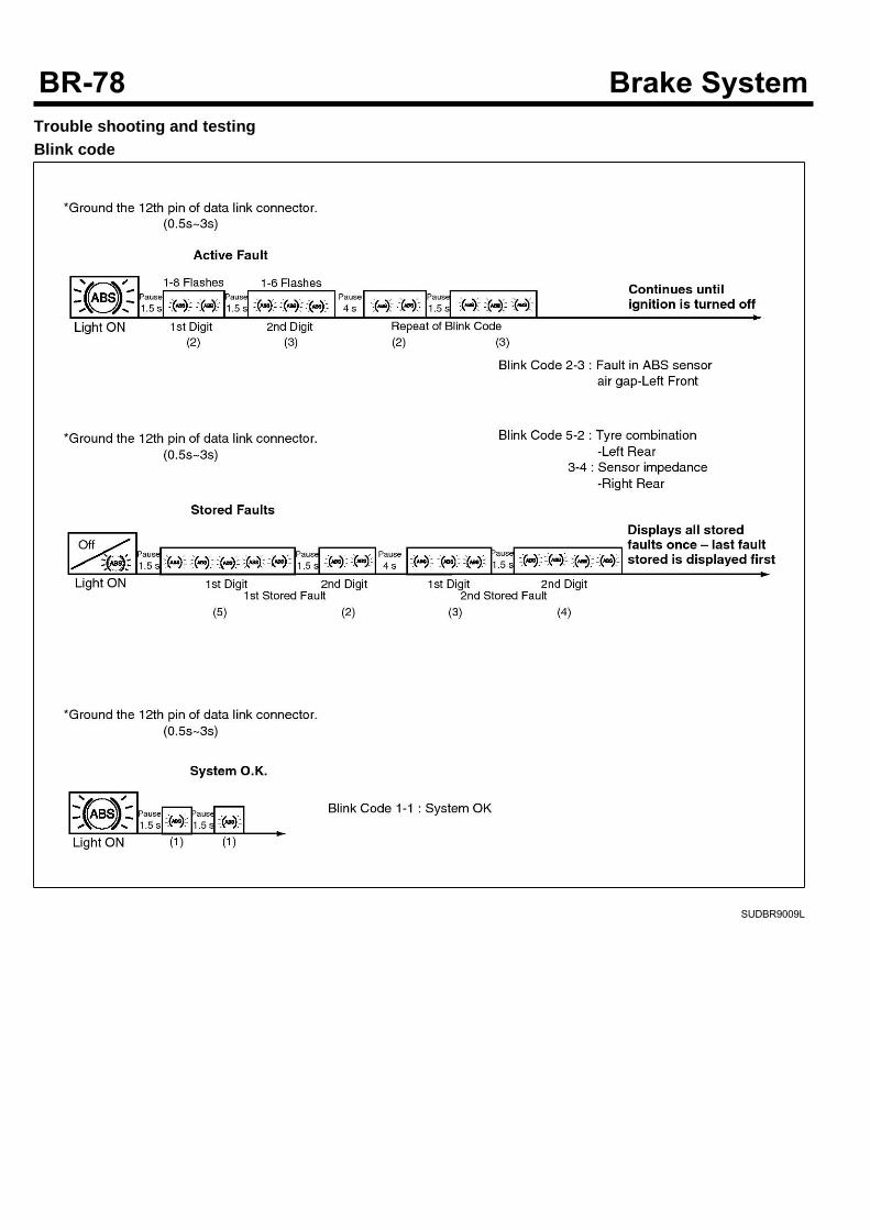
Trouble shooting and testingBlink code
SUDBR9009L
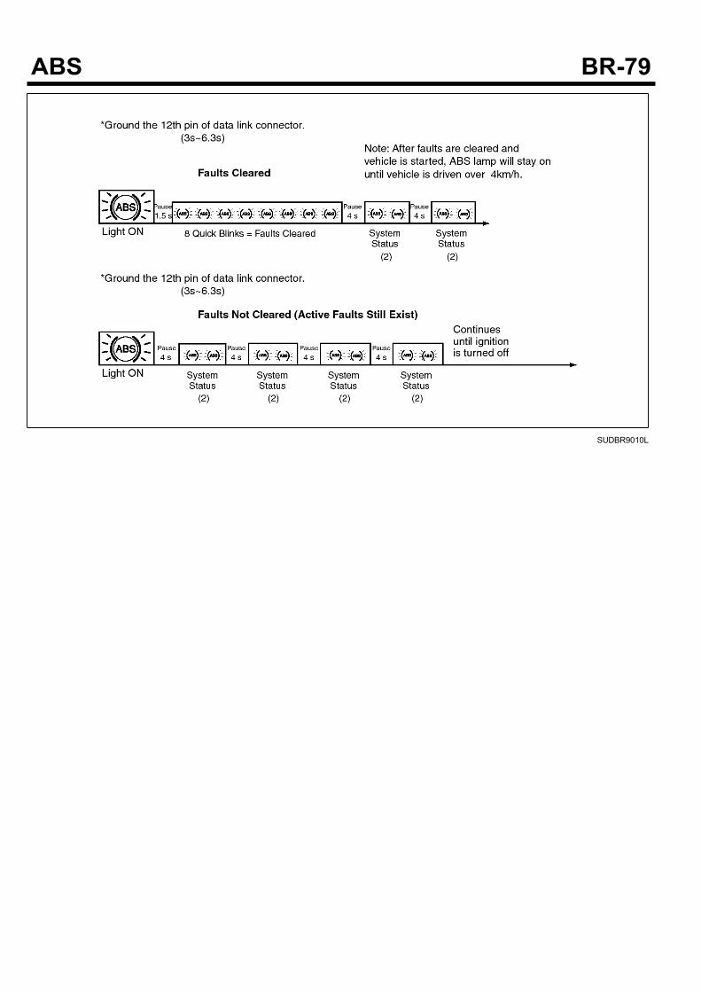
SUDBR9010L
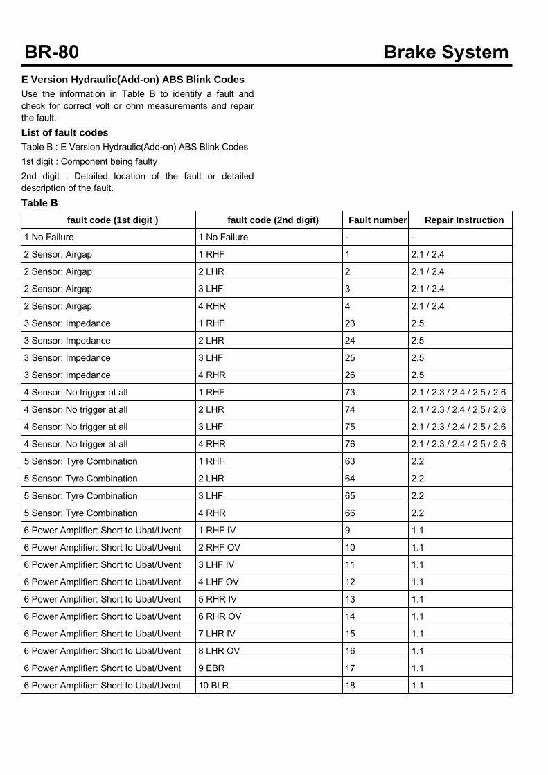
E Version Hydraulic(Add-on) ABS Blink CodesUse the information in Table B to identify a fault andcheck for correct volt or ohm measurements and repairthe fault.List of fault codesTable B : E Version Hydraulic(Add-on) ABS Blink Codes1st digit : Component being faulty2nd digit : Detailed location of the fault or detaileddescription of the fault.Table B
fault code (1st digit ) fault code (2nd digit) Fault number Repair Instruction
1 No Failure 1 No Failure - -
2 Sensor: Airgap 1 RHF 1 2.1 / 2.4
2 Sensor: Airgap 2 LHR 2 2.1 / 2.4
2 Sensor: Airgap 3 LHF 3 2.1 / 2.4
2 Sensor: Airgap 4 RHR 4 2.1 / 2.4
3 Sensor: Impedance 1 RHF 23 2.5
3 Sensor: Impedance 2 LHR 24 2.5
3 Sensor: Impedance 3 LHF 25 2.5
3 Sensor: Impedance 4 RHR 26 2.5
4 Sensor: No trigger at all 1 RHF 73 2.1 / 2.3 / 2.4 / 2.5 / 2.6
4 Sensor: No trigger at all 2 LHR 74 2.1 / 2.3 / 2.4 / 2.5 / 2.6
4 Sensor: No trigger at all 3 LHF 75 2.1 / 2.3 / 2.4 / 2.5 / 2.6
4 Sensor: No trigger at all 4 RHR 76 2.1 / 2.3 / 2.4 / 2.5 / 2.6
5 Sensor: Tyre Combination 1 RHF 63 2.2
5 Sensor: Tyre Combination 2 LHR 64 2.2
5 Sensor: Tyre Combination 3 LHF 65 2.2
5 Sensor: Tyre Combination 4 RHR 66 2.2
6 Power Amplifier: Short to Ubat/Uvent 1 RHF IV 9 1.1
6 Power Amplifier: Short to Ubat/Uvent 2 RHF OV 10 1.1
6 Power Amplifier: Short to Ubat/Uvent 3 LHF IV 11 1.1
6 Power Amplifier: Short to Ubat/Uvent 4 LHF OV 12 1.1
6 Power Amplifier: Short to Ubat/Uvent 5 RHR IV 13 1.1
6 Power Amplifier: Short to Ubat/Uvent 6 RHR OV 14 1.1
6 Power Amplifier: Short to Ubat/Uvent 7 LHR IV 15 1.1
6 Power Amplifier: Short to Ubat/Uvent 8 LHR OV 16 1.1
6 Power Amplifier: Short to Ubat/Uvent 9 EBR 17 1.1
6 Power Amplifier: Short to Ubat/Uvent 10 BLR 18 1.1
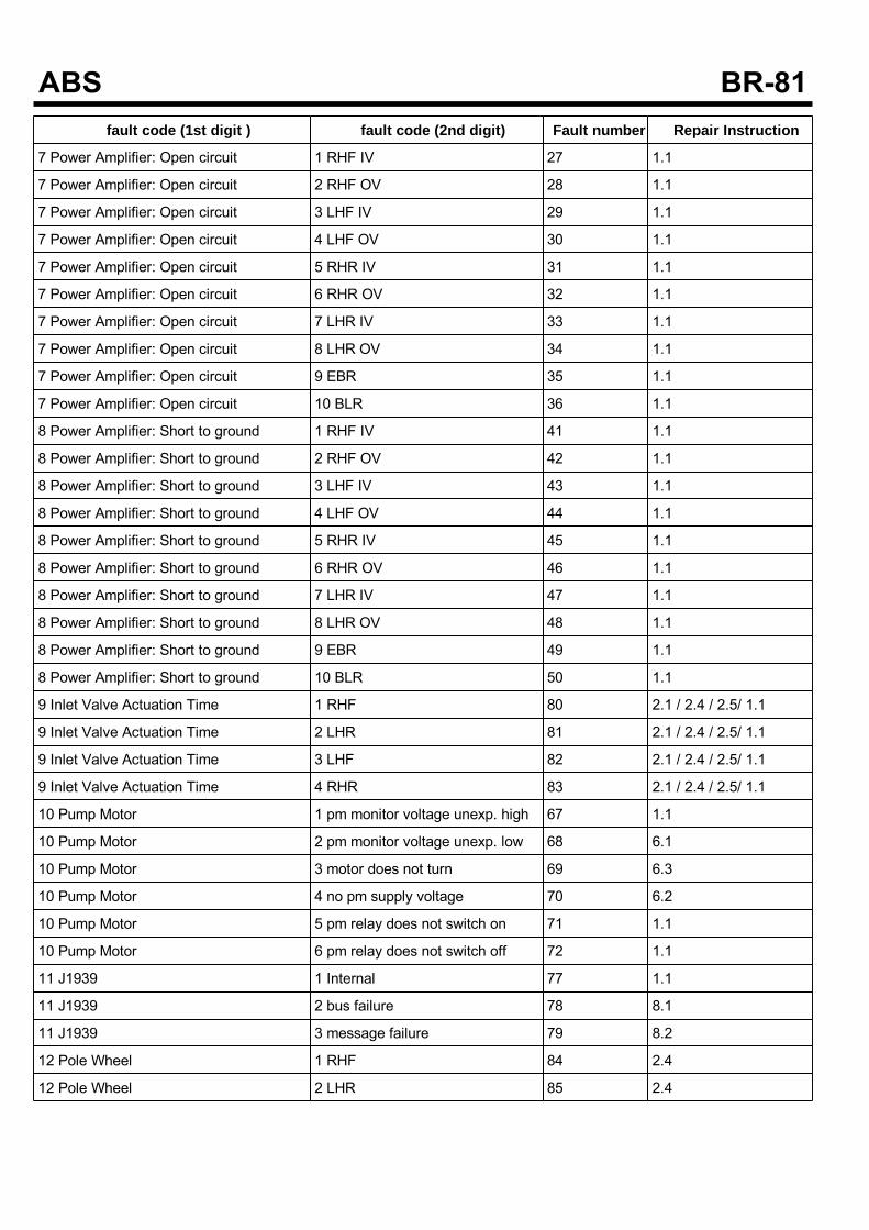
fault code (1st digit ) fault code (2nd digit) Fault number Repair Instruction
7 Power Amplifier: Open circuit 1 RHF IV 27 1.1
7 Power Amplifier: Open circuit 2 RHF OV 28 1.1
7 Power Amplifier: Open circuit 3 LHF IV 29 1.1
7 Power Amplifier: Open circuit 4 LHF OV 30 1.1
7 Power Amplifier: Open circuit 5 RHR IV 31 1.1
7 Power Amplifier: Open circuit 6 RHR OV 32 1.1
7 Power Amplifier: Open circuit 7 LHR IV 33 1.1
7 Power Amplifier: Open circuit 8 LHR OV 34 1.1
7 Power Amplifier: Open circuit 9 EBR 35 1.1
7 Power Amplifier: Open circuit 10 BLR 36 1.1
8 Power Amplifier: Short to ground 1 RHF IV 41 1.1
8 Power Amplifier: Short to ground 2 RHF OV 42 1.1
8 Power Amplifier: Short to ground 3 LHF IV 43 1.1
8 Power Amplifier: Short to ground 4 LHF OV 44 1.1
8 Power Amplifier: Short to ground 5 RHR IV 45 1.1
8 Power Amplifier: Short to ground 6 RHR OV 46 1.1
8 Power Amplifier: Short to ground 7 LHR IV 47 1.1
8 Power Amplifier: Short to ground 8 LHR OV 48 1.1
8 Power Amplifier: Short to ground 9 EBR 49 1.1
8 Power Amplifier: Short to ground 10 BLR 50 1.1
9 Inlet Valve Actuation Time 1 RHF 80 2.1 / 2.4 / 2.5/ 1.1
9 Inlet Valve Actuation Time 2 LHR 81 2.1 / 2.4 / 2.5/ 1.1
9 Inlet Valve Actuation Time 3 LHF 82 2.1 / 2.4 / 2.5/ 1.1
9 Inlet Valve Actuation Time 4 RHR 83 2.1 / 2.4 / 2.5/ 1.1
10 Pump Motor 1 pm monitor voltage unexp. high 67 1.1
10 Pump Motor 2 pm monitor voltage unexp. low 68 6.1
10 Pump Motor 3 motor does not turn 69 6.3
10 Pump Motor 4 no pm supply voltage 70 6.2
10 Pump Motor 5 pm relay does not switch on 71 1.1
10 Pump Motor 6 pm relay does not switch off 72 1.1
11 J1939 1 Internal 77 1.1
11 J1939 2 bus failure 78 8.1
11 J1939 3 message failure 79 8.2
12 Pole Wheel 1 RHF 84 2.4
12 Pole Wheel 2 LHR 85 2.4
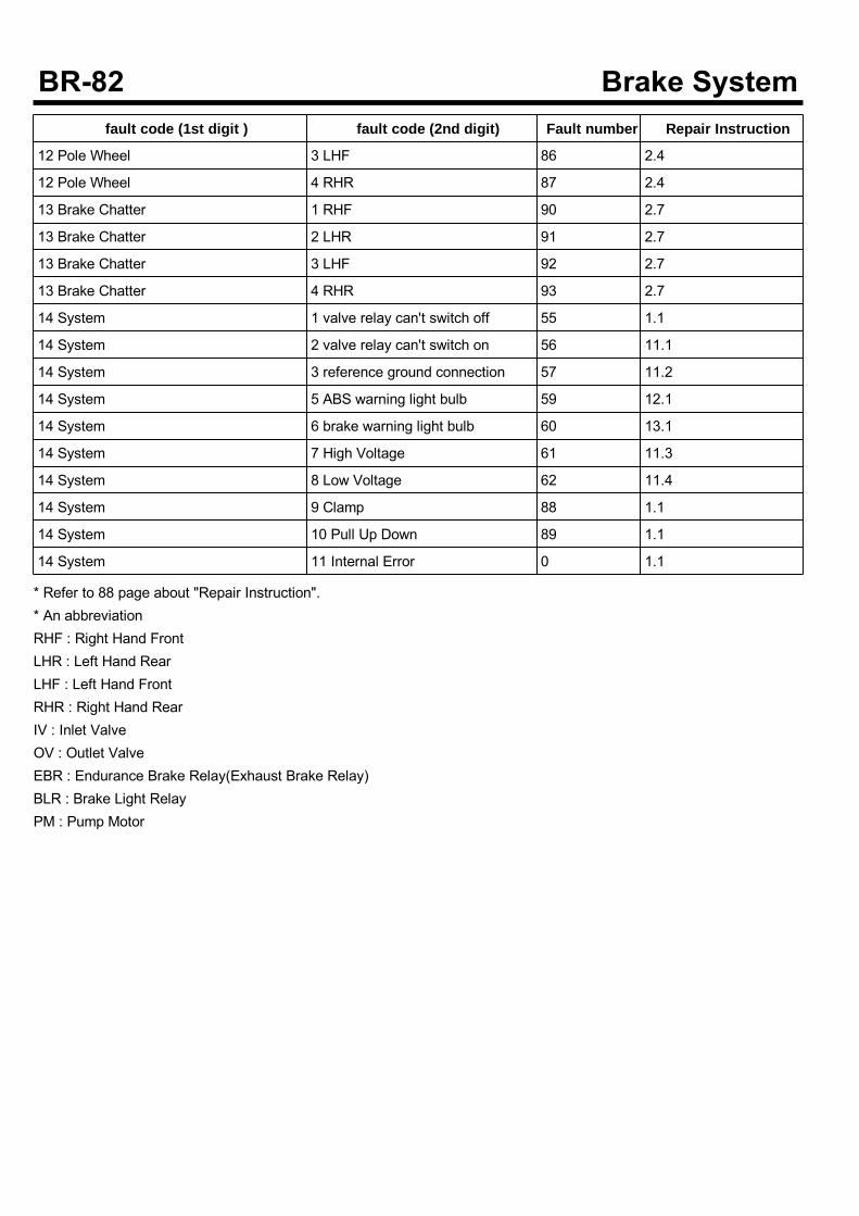
fault code (1st digit ) fault code (2nd digit) Fault number Repair Instruction
12 Pole Wheel 3 LHF 86 2.4
12 Pole Wheel 4 RHR 87 2.4
13 Brake Chatter 1 RHF 90 2.7
13 Brake Chatter 2 LHR 91 2.7
13 Brake Chatter 3 LHF 92 2.7
13 Brake Chatter 4 RHR 93 2.7
14 System 1 valve relay can't switch off 55 1.1
14 System 2 valve relay can't switch on 56 11.1
14 System 3 reference ground connection 57 11.2
14 System 5 ABS warning light bulb 59 12.1
14 System 6 brake warning light bulb 60 13.1
14 System 7 High Voltage 61 11.3
14 System 8 Low Voltage 62 11.4
14 System 9 Clamp 88 1.1
14 System 10 Pull Up Down 89 1.1
14 System 11 Internal Error 0 1.1
* Refer to 88 page about "Repair Instruction".* An abbreviationRHF : Right Hand FrontLHR : Left Hand RearLHF : Left Hand FrontRHR : Right Hand RearIV : Inlet ValveOV : Outlet ValveEBR : Endurance Brake Relay(Exhaust Brake Relay)BLR : Brake Light RelayPM : Pump Motor
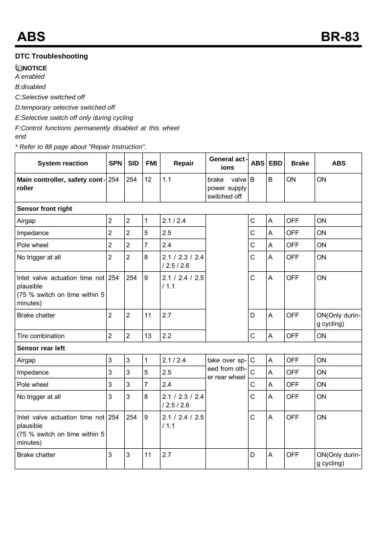
DTC TroubleshootingNOTICE
A:enabledB:disabledC:Selective switched offD:temporary selective switched offE:Selective switch off only during cyclingF:Control functions permanently disabled at this wheelend* Refer to 88 page about "Repair Instruction".
System reaction SPN SID FMI Repair General act -ions ABS EBD Brake ABS
Main controller, safety cont -roller
254 254 12 1.1 brake valvepower supplyswitched off
B B ON ON
Sensor front right
Airgap 2 2 1 2.1 / 2.4 C A OFF ON
Impedance 2 2 5 2.5 C A OFF ON
Pole wheel 2 2 7 2.4 C A OFF ON
No trigger at all 2 2 8 2.1 / 2.3 / 2.4/ 2.5 / 2.6
C A OFF ON
Inlet valve actuation time notplausible(75 % switch on time within 5minutes)
254 254 9 2.1 / 2.4 / 2.5/ 1.1
C A OFF ON
Brake chatter 2 2 11 2.7 D A OFF ON(Only durin-g cycling)
Tire combination 2 2 13 2.2 C A OFF ON
Sensor rear left
Airgap 3 3 1 2.1 / 2.4 take over sp-eed from oth-er rear wheel
C A OFF ON
Impedance 3 3 5 2.5 C A OFF ON
Pole wheel 3 3 7 2.4 C A OFF ON
No trigger at all 3 3 8 2.1 / 2.3 / 2.4/ 2.5 / 2.6
C A OFF ON
Inlet valve actuation time notplausible(75 % switch on time within 5minutes)
254 254 9 2.1 / 2.4 / 2.5/ 1.1
C A OFF ON
Brake chatter 3 3 11 2.7 D A OFF ON(Only durin-g cycling)
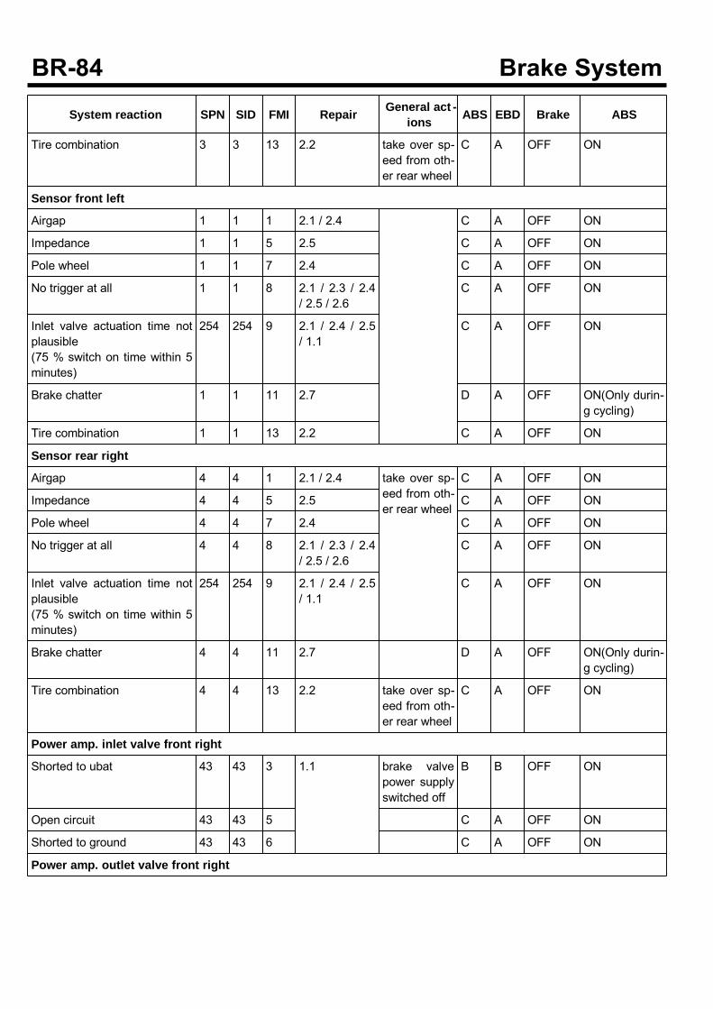
System reaction SPN SID FMI Repair General act -ions ABS EBD Brake ABS
Tire combination 3 3 13 2.2 take over sp-eed from oth-er rear wheel
C A OFF ON
Sensor front left
Airgap 1 1 1 2.1 / 2.4 C A OFF ON
Impedance 1 1 5 2.5 C A OFF ON
Pole wheel 1 1 7 2.4 C A OFF ON
No trigger at all 1 1 8 2.1 / 2.3 / 2.4/ 2.5 / 2.6
C A OFF ON
Inlet valve actuation time notplausible(75 % switch on time within 5minutes)
254 254 9 2.1 / 2.4 / 2.5/ 1.1
C A OFF ON
Brake chatter 1 1 11 2.7 D A OFF ON(Only durin-g cycling)
Tire combination 1 1 13 2.2 C A OFF ON
Sensor rear right
Airgap 4 4 1 2.1 / 2.4 take over sp-eed from oth-er rear wheel
C A OFF ON
Impedance 4 4 5 2.5 C A OFF ON
Pole wheel 4 4 7 2.4 C A OFF ON
No trigger at all 4 4 8 2.1 / 2.3 / 2.4/ 2.5 / 2.6
C A OFF ON
Inlet valve actuation time notplausible(75 % switch on time within 5minutes)
254 254 9 2.1 / 2.4 / 2.5/ 1.1
C A OFF ON
Brake chatter 4 4 11 2.7 D A OFF ON(Only durin-g cycling)
Tire combination 4 4 13 2.2 take over sp-eed from oth-er rear wheel
C A OFF ON
Power amp. inlet valve front right
Shorted to ubat 43 43 3 1.1 brake valvepower supplyswitched off
B B OFF ON
Open circuit 43 43 5 C A OFF ON
Shorted to ground 43 43 6 C A OFF ON
Power amp. outlet valve front right
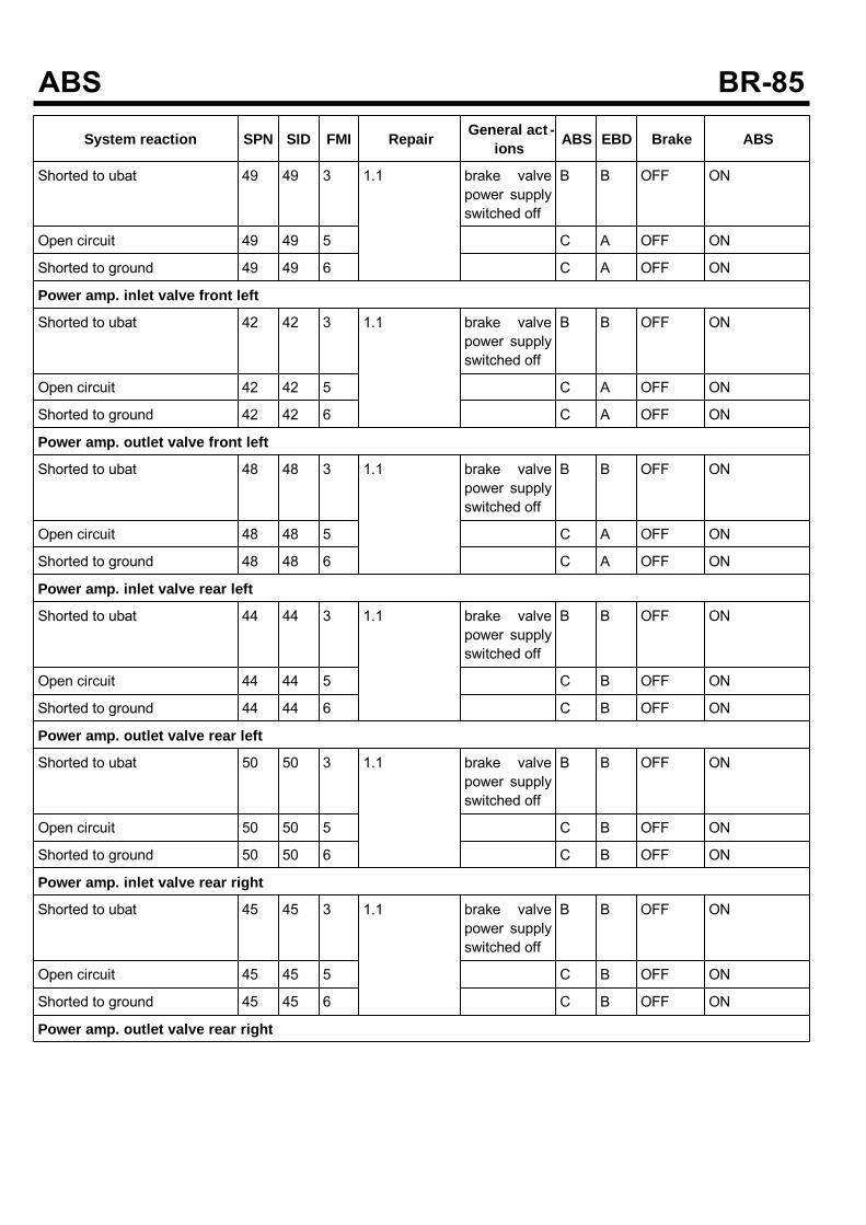
System reaction SPN SID FMI Repair General act -ions ABS EBD Brake ABS
Shorted to ubat 49 49 3 1.1 brake valvepower supplyswitched off
B B OFF ON
Open circuit 49 49 5 C A OFF ON
Shorted to ground 49 49 6 C A OFF ON
Power amp. inlet valve front left
Shorted to ubat 42 42 3 1.1 brake valvepower supplyswitched off
B B OFF ON
Open circuit 42 42 5 C A OFF ON
Shorted to ground 42 42 6 C A OFF ON
Power amp. outlet valve front left
Shorted to ubat 48 48 3 1.1 brake valvepower supplyswitched off
B B OFF ON
Open circuit 48 48 5 C A OFF ON
Shorted to ground 48 48 6 C A OFF ON
Power amp. inlet valve rear left
Shorted to ubat 44 44 3 1.1 brake valvepower supplyswitched off
B B OFF ON
Open circuit 44 44 5 C B OFF ON
Shorted to ground 44 44 6 C B OFF ON
Power amp. outlet valve rear left
Shorted to ubat 50 50 3 1.1 brake valvepower supplyswitched off
B B OFF ON
Open circuit 50 50 5 C B OFF ON
Shorted to ground 50 50 6 C B OFF ON
Power amp. inlet valve rear right
Shorted to ubat 45 45 3 1.1 brake valvepower supplyswitched off
B B OFF ON
Open circuit 45 45 5 C B OFF ON
Shorted to ground 45 45 6 C B OFF ON
Power amp. outlet valve rear right
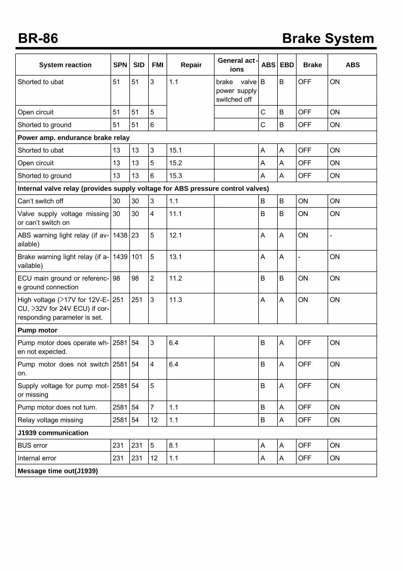
System reaction SPN SID FMI Repair General act -ions ABS EBD Brake ABS
Shorted to ubat 51 51 3 1.1 brake valvepower supplyswitched off
B B OFF ON
Open circuit 51 51 5 C B OFF ON
Shorted to ground 51 51 6 C B OFF ON
Power amp. endurance brake relay
Shorted to ubat 13 13 3 15.1 A A OFF ON
Open circuit 13 13 5 15.2 A A OFF ON
Shorted to ground 13 13 6 15.3 A A OFF ON
Internal valve relay (provides supply voltage for ABS pressure control valves)
Can’t switch off 30 30 3 1.1 B B ON ON
Valve supply voltage missingor can’t switch on
30 30 4 11.1 B B ON ON
ABS warning light relay (if av-ailable)
1438 23 5 12.1 A A ON -
Brake warning light relay (if a-vailable)
1439 101 5 13.1 A A - ON
ECU main ground or referenc-e ground connection
98 98 2 11.2 B B ON ON
High voltage (>17V for 12V-E-CU, >32V for 24V ECU) if cor-responding parameter is set.
251 251 3 11.3 A A ON ON
Pump motor
Pump motor does operate wh-en not expected.
2581 54 3 6.4 B A OFF ON
Pump motor does not switchon.
2581 54 4 6.4 B A OFF ON
Supply voltage for pump mot-or missing
2581 54 5 B A OFF ON
Pump motor does not turn. 2581 54 7 1.1 B A OFF ON
Relay voltage missing 2581 54 12 1.1 B A OFF ON
J1939 communication
BUS error 231 231 5 8.1 A A OFF ON
Internal error 231 231 12 1.1 A A OFF ON
Message time out(J1939)
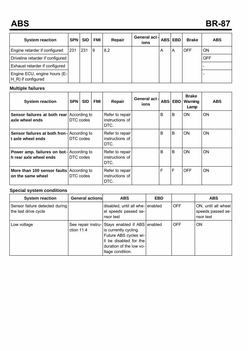
System reaction SPN SID FMI Repair General act -ions ABS EBD Brake ABS
Engine retarder if configured 231 231 9 8.2 A A OFF ON
Driveline retarder if configured OFF
Exhaust retarder if configured -
Engine ECU, engine hours (E-H_R) if configured
-
Multiple failures
System reaction SPN SID FMI Repair General act -ions ABS EBD
BrakeWarning
LampABS
Sensor failures at both rearaxle wheel ends
According toDTC codes
Refer to repairinstructions ofDTC.
B B ON ON
Sensor failures at both fron -t axle wheel ends
According toDTC codes
Refer to repairinstructions ofDTC.
B B ON ON
Power amp. failures on bot -h rear axle wheel ends
According toDTC codes
Refer to repairinstructions ofDTC.
B B ON ON
More than 100 sensor faultson the same wheel
According toDTC codes
Refer to repairinstructions ofDTC.
F F OFF ON
Special system conditionsSystem reaction General actions ABS EBD ABS
Sensor failure detected duringthe last drive cycle
disabled, until all whe-el speeds passed se-nsor test
enabled OFF ON, until all wheelspeeds passed se-nsor test
Low voltage See repair instru-ction 11.4
Stays enabled if ABSis currently cycling.Future ABS cycles wi-ll be disabled for theduration of the low vo-ltage condition.
enabled OFF ON
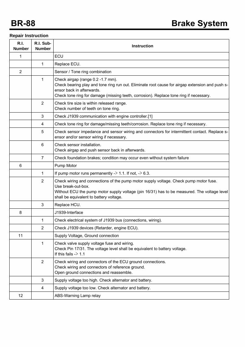
Repair InstructionR.I.
NumberR.I. Sub-Number Instruction
1 ECU
1 Replace ECU.
2 Sensor / Tone ring combination
1 Check airgap (range 0.2 -1.7 mm).Check bearing play and tone ring run out. Eliminate root cause for airgap extension and push s-ensor back in afterwards.Check tone ring for damage (missing teeth, corrosion). Replace tone ring if necessary.
2 Check tire size is within released range.Check number of teeth on tone ring.
3 Check J1939 communication with engine controller.[1]
4 Check tone ring for damage/missing teeth/corrosion. Replace tone ring if necessary.
5 Check sensor impedance and sensor wiring and connectors for intermittent contact. Replace s-ensor and/or sensor wiring if necessary.
6 Check sensor installation.Check airgap and push sensor back in afterwards.
7 Check foundation brakes; condition may occur even without system failure
6 Pump Motor
1 If pump motor runs permanently -> 1.1. If not, -> 6.3.
2 Check wiring and connections of the pump motor supply voltage. Check pump motor fuse.Use break-out-box.Without ECU the pump motor supply voltage (pin 16/31) has to be measured. The voltage levelshall be equivalent to battery voltage.
3 Replace HCU.
8 J1939-Interface
1 Check electrical system of J1939 bus (connections, wiring).
2 Check J1939 devices (Retarder, engine ECU).
11 Supply Voltage, Ground connection
1 Check valve supply voltage fuse and wiring.Check Pin 17/31. The voltage level shall be equivalent to battery voltage.If this fails -> 1.1
2 Check wiring and connectors of the ECU ground connections.Check wiring and connectors of reference ground.Open ground connections and reassemble.
3 Supply voltage too high. Check alternator and battery.
4 Supply voltage too low. Check alternator and battery.
12 ABS-Warning Lamp relay
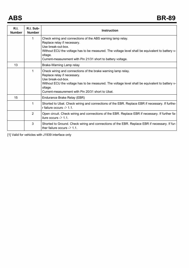
R.I.Number
R.I. Sub-Number Instruction
1 Check wiring and connections of the ABS warning lamp relay.Replace relay if necessary.Use break-out-box.Without ECU the voltage has to be measured. The voltage level shall be equivalent to battery v-oltage.Current-measurement with Pin 21/31 short to battery voltage.
13 Brake-Warning Lamp relay
1 Check wiring and connections of the brake warning lamp relay.Replace relay if necessary.Use break-out-box.Without ECU the voltage has to be measured. The voltage level shall be equivalent to battery v-oltage.Current-measurement with Pin 20/31 short to Ubat.
15 Endurance Brake Relay (EBR)
1 Shorted to Ubat. Check wiring and connections of the EBR. Replace EBR if necessary. If furthe-r failure occurs -> 1.1.
2 Open circuit. Check wiring and connections of the EBR. Replace EBR if necessary. If further fa-ilure occurs -> 1.1.
3 Shorted to Ground. Check wiring and connections of the EBR. Replace EBR if necessary. If fur-ther failure occurs -> 1.1.
[1] Valid for vehicles with J1939 interface only
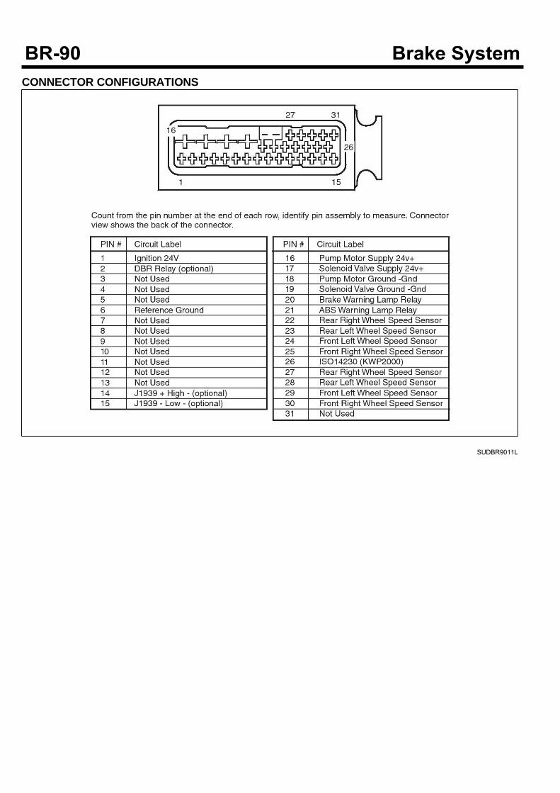
CONNECTOR CONFIGURATIONS
SUDBR9011L
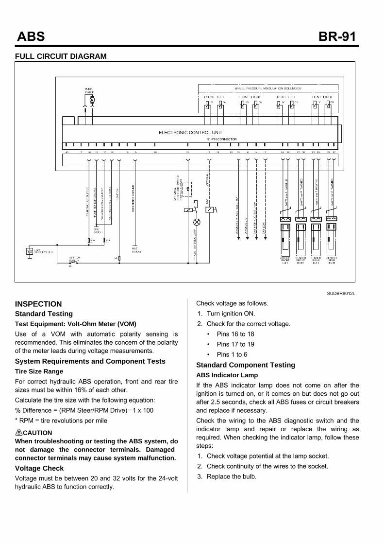
FULL CIRCUIT DIAGRAM
SUDBR9012L
INSPECTIONStandard TestingTest Equipment: Volt-Ohm Meter (VOM)Use of a VOM with automatic polarity sensing isrecommended. This eliminates the concern of the polarityof the meter leads during voltage measurements.System Requirements and Component TestsTire Size RangeFor correct hydraulic ABS operation, front and rear tiresizes must be within 16% of each other.Calculate the tire size with the following equation:% Difference = (RPM Steer/RPM Drive)−1 x 100* RPM = tire revolutions per mile
CAUTIONWhen troubleshooting or testing the ABS system, donot damage the connector terminals. Damagedconnector terminals may cause system malfunction.Voltage CheckVoltage must be between 20 and 32 volts for the 24-volthydraulic ABS to function correctly.
Check voltage as follows.1. Turn ignition ON.2. Check for the correct voltage.
• Pins 16 to 18• Pins 17 to 19• Pins 1 to 6
Standard Component TestingABS Indicator LampIf the ABS indicator lamp does not come on after theignition is turned on, or it comes on but does not go outafter 2.5 seconds, check all ABS fuses or circuit breakersand replace if necessary.Check the wiring to the ABS diagnostic switch and theindicator lamp and repair or replace the wiring asrequired. When checking the indicator lamp, follow thesesteps:1. Check voltage potential at the lamp socket.2. Check continuity of the wires to the socket.3. Replace the bulb.
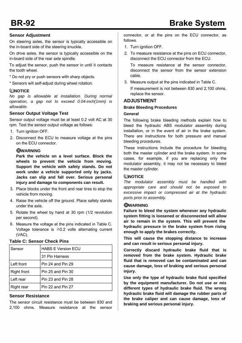
Sensor AdjustmentOn steering axles, the sensor is typically accessible onthe in-board side of the steering knuckle.On drive axles, the sensor is typically accessible on thein-board side of the rear axle spindle.To adjust the sensor, push the sensor in until it contactsthe tooth wheel.* Do not pry or push sensors with sharp objects.* Sensors will self-adjust during wheel rotation.
NOTICENo gap is allowable at installation. During normaloperation, a gap not to exceed 0.04-inch(1mm) isallowable.Sensor Output Voltage TestSensor output voltage must be at least 0.2 volt AC at 30rpm. Test the sensor output voltage as follows:1. Turn ignition OFF.2. Disconnect the ECU to measure voltage at the pinson the ECU connector.
WARNINGPark the vehicle on a level surface. Block thewheels to prevent the vehicle from moving.Support the vehicle with safety stands. Do notwork under a vehicle supported only by jacks.Jacks can slip and fall over. Serious personalinjury and damage to components can result.
3. Place blocks under the front and rear tires to stop thevehicle from moving.
4. Raise the vehicle off the ground. Place safety standsunder the axle.
5. Rotate the wheel by hand at 30 rpm (1/2 revolutionper second).
6. Measure the voltage at the pins indicated in Table C.Voltage tolerance is ≥0.2 volts alternating current(VAC).
Table C: Sensor Check PinsSensor HABS E Version ECU
31 Pin Harness
Left front Pin 24 and Pin 29
Right front Pin 25 and Pin 30
Left rear Pin 23 and Pin 28
Right rear Pin 22 and Pin 27
Sensor ResistanceThe sensor circuit resistance must be between 830 and2,100 ohms. Measure resistance at the sensor
connector, or at the pins on the ECU connector, asfollows.1. Turn ignition OFF.2. To measure resistance at the pins on ECU connector,disconnect the ECU connector from the ECU.To measure resistance at the sensor connector,disconnect the sensor from the sensor extensioncable.
3. Measure output at the pins indicated in Table C.If measurement is not between 830 and 2,100 ohms,replace the sensor.
ADJUSTMENTBrake Bleeding ProceduresGeneralThe following brake bleeding methods explain how tobleed the hydraulic ABS modulator assembly duringinstallation, or in the event of air in the brake system.There are instructions for both pressure and manualbleeding procedures.These instructions include the procedure for bleedingboth the master cylinder and the brake system. In somecases, for example, if you are replacing only themodulator assembly, it may not be necessary to bleedthe master cylinder.
NOTICEThe modulator assembly must be handled withappropriate care and should not be exposed toexcessive impact or compressed air at the hydraulicports prior to assembly.
WARNINGFailure to bleed the system whenever any hydraulicsystem fitting is loosened or disconnected will allowair to remain in the system. This will prevent thehydraulic pressure in the brake system from risingenough to apply the brakes correctly.This will cause the stopping distance to increaseand can result in serious personal injury.Correctly discard hydraulic brake fluid that isremoved from the brake system. Hydraulic brakefluid that is removed can be contaminated and cancause damage, loss of braking and serious personalinjury.Use only the type of hydraulic brake fluid specifiedby the equipment manufacturer. Do not use or mixdifferent types of hydraulic brake fluid. The wronghydraulic brake fluid will damage the rubber parts ofthe brake caliper and can cause damage, loss ofbraking and serious personal injury.
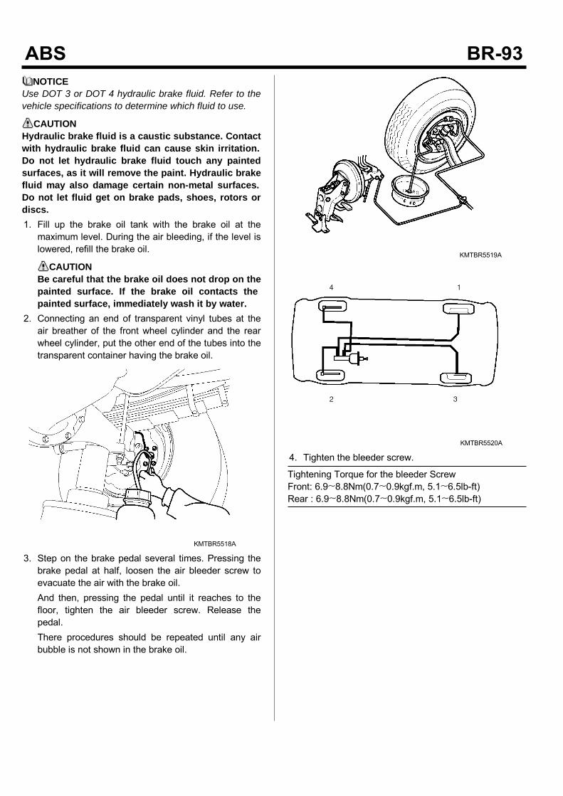
NOTICEUse DOT 3 or DOT 4 hydraulic brake fluid. Refer to thevehicle specifications to determine which fluid to use.
CAUTIONHydraulic brake fluid is a caustic substance. Contactwith hydraulic brake fluid can cause skin irritation.Do not let hydraulic brake fluid touch any paintedsurfaces, as it will remove the paint. Hydraulic brakefluid may also damage certain non-metal surfaces.Do not let fluid get on brake pads, shoes, rotors ordiscs.1. Fill up the brake oil tank with the brake oil at themaximum level. During the air bleeding, if the level islowered, refill the brake oil.
CAUTIONBe careful that the brake oil does not drop on thepainted surface. If the brake oil contacts thepainted surface, immediately wash it by water.
2. Connecting an end of transparent vinyl tubes at theair breather of the front wheel cylinder and the rearwheel cylinder, put the other end of the tubes into thetransparent container having the brake oil.
KMTBR5518A
3. Step on the brake pedal several times. Pressing thebrake pedal at half, loosen the air bleeder screw toevacuate the air with the brake oil.And then, pressing the pedal until it reaches to thefloor, tighten the air bleeder screw. Release thepedal.There procedures should be repeated until any airbubble is not shown in the brake oil.
KMTBR5519A
KMTBR5520A
4. Tighten the bleeder screw.
Tightening Torque for the bleeder ScrewFront: 6.9~8.8Nm(0.7~0.9kgf.m, 5.1~6.5lb-ft)Rear : 6.9~8.8Nm(0.7~0.9kgf.m, 5.1~6.5lb-ft)
ABS ModulatorREMOVAL
CAUTIONThe modulator assembly contains hydraulic brakefluid, a caustic substance. Remove the valvecarefully so that fluid does not leak and cause skinirritation or damage to components.
NOTICEIf there is interference, the entire bracket and valveassembly can be removed.1. Apply the parking brakes. Block the front and reartires to prevent vehicle movement.
2. Place a container under the modulator assembly tocatch leaking brake fluid.
3. Disconnect the electrical harness connector from themodulator assembly.
4. Mark the six brake lines for ease of installation.Disconnect the lines from the modulator assembly.
5. Remove the three mounting cap screws and washersthat attach the modulator assembly to the bracket.
NOTICEWhenever any hydraulic system fitting is loosened ordisconnected, the entire system must be bled toremove any air that may have entered. Refer to“Brake Bleeding Procedures” in this section.
6. Remove the modulator assembly after disconnect theECU.
7. Use a 4 mm Allen wrench to loosen and remove thefour mounting screws that attach the ECU module tothe modulator valve.
8. Carefully remove the ECU by lifting straight out. Toavoid damage, do not twist the ECU during removal.
INSTALLATION1. Position the old ECU onto the new modulator valve.Apply gentle pressure to seat the ECU. Motorconnector must achieve full depth onto the housing.The gap between the modulator and the ECU mustnot exceed 0.08-inch (2 mm).
2. Use a 4 mm Allen wrench to tighten the fourmounting screws that attach the ECU to themodulator. Tighten to 1.5 Nm(0.16 kgf.m , 1.17 lb-ft).Do not exceed this torque. The metal sleeves on theECU housing must rest flat on the body of themodulator.
3. When the ECU is correctly installed with the metalsleeves flat on the modulator, tighten the bolts to2.5~3.5 Nm(0.25~0.35 kgf.m , 1.8~2.6 lb-ft).
4. Position the modulator assembly in place on thevehicle.
5. Tighten the three mounting nuts to 22 Nm(2.2 kgf.m ,16.2 lb-ft).
6. Connect the electrical harnesses to the modulatorassembly.
7. Connect and tighten the brake line connections.8. Bleed the brake system, per the followinginstructions.
Wheel Speed SensorDESCRIPTIONSensor Lube SpecificationWABCO specifications call for a sensor lubricant with thefollowing characteristics.Lube must be mineral oil-based and containmolydisulfide. It should have excellent anti-corrosion andadhesion characteristics and be capable of continuousfunction in a temperature range of –40° to 300°F (–40° to150°C).
REPLACEMENTFRONT AXLERemoval
WARNINGTo prevent serious eye injury, always wear safe eyeprotection when you perform vehicle maintenanceor service.Park the vehicle on a level surface. Block the wheelsto prevent the vehicle from moving. Support thevehicle with safety stands. Do not work under avehicle supported only by jacks. Jacks can slip andfall over. Serious personal injury and damage tocomponents can result.
CAUTIONTo avoid damage to the electrical system or HABScomponents, when welding on a HABS-equippedvehicle disconnect the power connector from theECU.1. Park the vehicle on a level surface. Apply the parkingbrakes.Block the rear tires to prevent the vehicle frommoving.If necessary, raise the front tires off the ground.Place safety stands under the axle.
2. Disconnect the fasteners that hold the sensor cableto other components.
3. Disconnect the sensor cable from the chassisharness.
4. Remove the sensor from the sensor holder. Twist andpull the sensor to remove it from the sensor bracket.Do not pull on the cable.
Installation1. Connect the sensor cable to the chassis harness.2. Install the fasteners used to hold the sensor cable inplace.
3. Apply a WABCO-recommended lubricant to thesensor spring clip and sensor.
4. Install the sensor spring clip. Verify that the springclip tabs are on the inboard side of the vehicle.
5. With the tabs on the inboard side, push the sensorspring clip into the bushing in the steering knuckleuntil the clip stops.
6. Push the sensor completely into the sensor springclip until it contacts the tooth wheel.
7. Fasten the sensor cable every 12 inches(305mm).Correctly bundle and store any excess cable in thesub-frame.
8. Remove the blocks and safety stands.9. Perform a voltage output check to ensure correctinstallation.
REAR AXLERemoval1. Apply the parking brake. Block the front tires toprevent vehicle movement.
2. Raise the rear tires off the ground. Place safetystands under the axle.
3. If the rear tire must be removed to gain access to thesensor, release the parking brake to release thebrake shoe.Remove the wheel and tire assembly from the axle.
4. Remove the sensor from the mounting block. Use atwisting motion if necessary. Do not pull on the cable.
5. Disconnect the sensor cable from the chassisharness.
6. Remove the sensor cable from any cable clamps orclips.
7. Remove the sensor spring clip from the sensorbracket.
Installation1. Connect the new sensor cable to the chassisharness.
2. Press the sensor spring clip into the sensor bracket,located on the rear axle, until it stops. Verify that thetabs are on the inboard side.
3. Apply a WABCO-recommended lubricant to thesensor.
4. Push the sensor completely into the spring clip until itcontacts the tooth wheel.
5. Reattach the sensor cable to the cable clamps orclips.
6. Fasten the sensor cable every 12 inches(305mm).Correctly bundle and store excess cable in thesub-frame.
7. Replace the tire and remove the safety stands. Lowerthe vehicle and remove the blocks from the fronttires.
8. Perform a voltage output check to ensure correctinstallation.
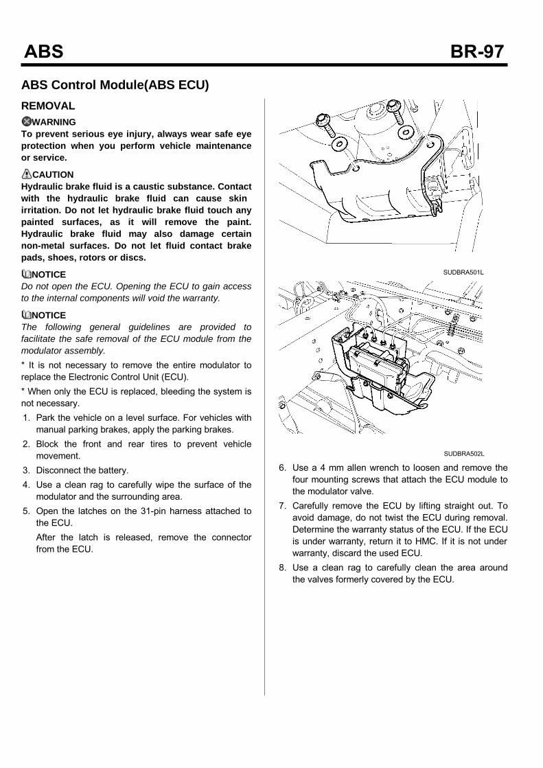
ABS Control Module(ABS ECU)REMOVAL
WARNINGTo prevent serious eye injury, always wear safe eyeprotection when you perform vehicle maintenanceor service.
CAUTIONHydraulic brake fluid is a caustic substance. Contactwith the hydraulic brake fluid can cause skinirritation. Do not let hydraulic brake fluid touch anypainted surfaces, as it will remove the paint.Hydraulic brake fluid may also damage certainnon-metal surfaces. Do not let fluid contact brakepads, shoes, rotors or discs.
NOTICEDo not open the ECU. Opening the ECU to gain accessto the internal components will void the warranty.
NOTICEThe following general guidelines are provided tofacilitate the safe removal of the ECU module from themodulator assembly.* It is not necessary to remove the entire modulator toreplace the Electronic Control Unit (ECU).* When only the ECU is replaced, bleeding the system isnot necessary.1. Park the vehicle on a level surface. For vehicles withmanual parking brakes, apply the parking brakes.
2. Block the front and rear tires to prevent vehiclemovement.
3. Disconnect the battery.4. Use a clean rag to carefully wipe the surface of themodulator and the surrounding area.
5. Open the latches on the 31-pin harness attached tothe ECU.After the latch is released, remove the connectorfrom the ECU.
SUDBRA501L
SUDBRA502L
6. Use a 4 mm allen wrench to loosen and remove thefour mounting screws that attach the ECU module tothe modulator valve.
7. Carefully remove the ECU by lifting straight out. Toavoid damage, do not twist the ECU during removal.Determine the warranty status of the ECU. If the ECUis under warranty, return it to HMC. If it is not underwarranty, discard the used ECU.
8. Use a clean rag to carefully clean the area aroundthe valves formerly covered by the ECU.
INSTALLATIONCAUTION
Excessive force in positioning the ECU onto themodulator will damage the ECU housing. Do notforce the ECU into position.Use a gentle, even pressure when positioning theECU.1. Position the ECU onto the modulator valve. Applygentle pressure to seat the ECU. Motor connectorsmust achieve full depth into the housing. The gapbetween the modulator and ECU must not exceed0.08-inch (2 mm).
2. Use a 4 mm Allen wrench to tighten the fourmounting screws that attach the ECU to themodulator. Tighten to 1.5 Nm(0.16 kgf.m , 1.17 lb-ft).Do not exceed this torque. The metal sleeves on theECU housing must rest flat on the body of themodulator.
3. When the ECU is correctly installed with the metalsleeves flat on the modulator, tighten the bolts to2.5~3.5 Nm(0.25~0.35 kgf.m , 1.8~2.6 lb-ft).
WARNINGElectrical connectors must be correctly installedwith the latch pushed in to lock the connector.Failure to do so may allow the connectors tocome loose or disconnect resulting in loss ofABS function.
4. Attach the 31-pin harness connector to the ECU.5. Connect the battery.
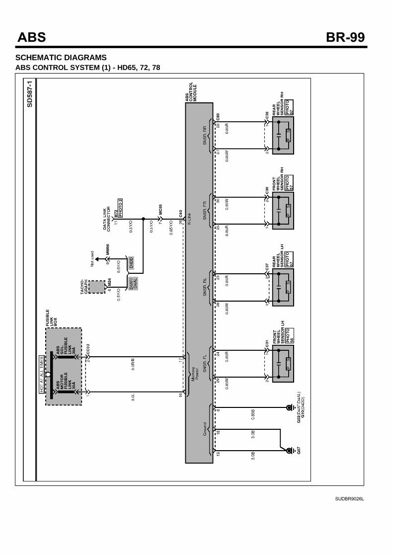
SCHEMATIC DIAGRAMSABS CONTROL SYSTEM (1) - HD65, 72, 78
SUDBR9026L
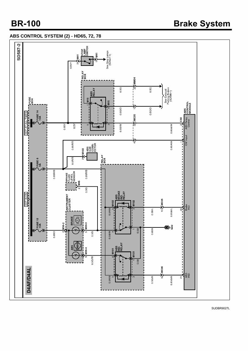
ABS CONTROL SYSTEM (2) - HD65, 72, 78
SUDBR9027L
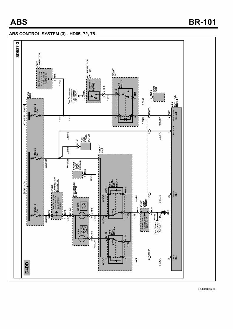
ABS CONTROL SYSTEM (3) - HD65, 72, 78
SUDBR9028L
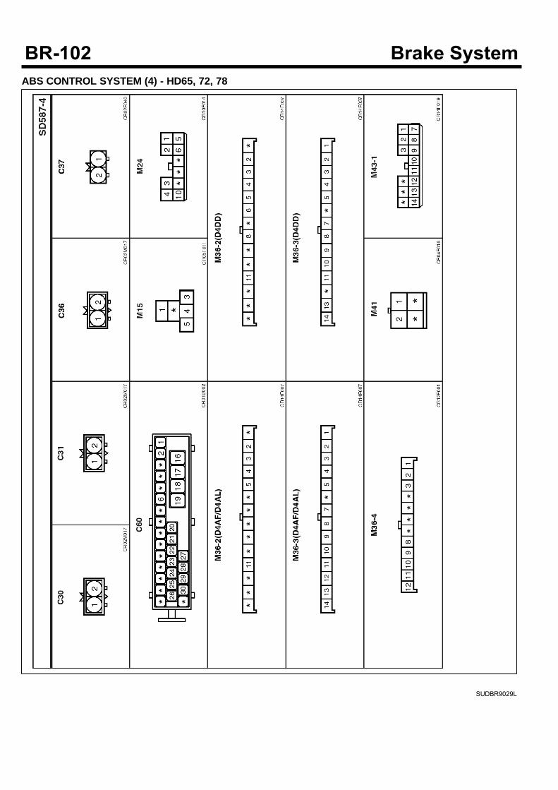
ABS CONTROL SYSTEM (4) - HD65, 72, 78
SUDBR9029L
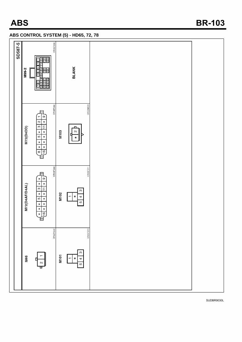
ABS CONTROL SYSTEM (5) - HD65, 72, 78
SUDBR9030L
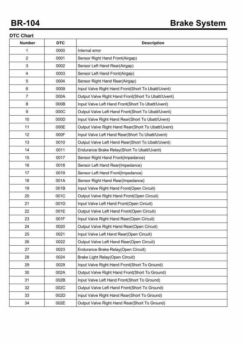
DTC ChartNumber DTC Description
1 0000 Internal error
2 0001 Sensor Right Hand Front(Airgap)
3 0002 Sensor Left Hand Rear(Airgap)
4 0003 Sensor Left Hand Front(Airgap)
5 0004 Sensor Right Hand Rear(Airgap)
6 0009 Input Valve Right Hand Front(Short To Ubatt/Uvent)
7 000A Output Valve Right Hand Front(Short To Ubatt/Uvent)
8 000B Input Valve Left Hand Front(Short To Ubatt/Uvent)
9 000C Output Valve Left Hand Front(Short To Ubatt/Uvent)
10 000D Input Valve Right Hand Rear(Short To Ubatt/Uvent)
11 000E Output Valve Right Hand Rear(Short To Ubatt/Uvent)
12 000F Input Valve Left Hand Rear(Short To Ubatt/Uvent)
13 0010 Output Valve Left Hand Rear(Short To Ubatt/Uvent)
14 0011 Endurance Brake Relay(Short To Ubatt/Uvent)
15 0017 Sensor Right Hand Front(Impedance)
16 0018 Sensor Left Hand Rear(Impedance)
17 0019 Sensor Left Hand Front(Impedance)
18 001A Sensor Right Hand Rear(Impedance)
19 001B Input Valve Right Hand Front(Open Circuit)
20 001C Output Valve Right Hand Front(Open Circuit)
21 001D Input Valve Left Hand Front(Open Circuit)
22 001E Output Valve Left Hand Front(Open Circuit)
23 001F Input Valve Right Hand Rear(Open Circuit)
24 0020 Output Valve Right Hand Rear(Open Circuit)
25 0021 Input Valve Left Hand Rear(Open Circuit)
26 0022 Output Valve Left Hand Rear(Open Circuit)
27 0023 Endurance Brake Relay(Open Circuit)
28 0024 Brake Light Relay(Open Circuit)
29 0029 Input Valve Right Hand Front(Short To Ground)
30 002A Output Valve Right Hand Front(Short To Ground)
31 002B Input Valve Left Hand Front(Short To Ground)
32 002C Output Valve Left Hand Front(Short To Ground)
33 002D Input Valve Right Hand Rear(Short To Ground)
34 002E Output Valve Right Hand Rear(Short To Ground)
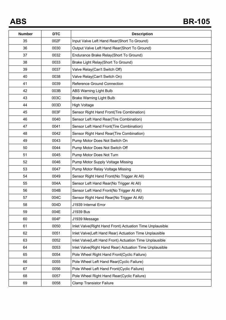
Number DTC Description
35 002F Input Valve Left Hand Rear(Short To Ground)
36 0030 Output Valve Left Hand Rear(Short To Ground)
37 0032 Endurance Brake Relay(Short To Ground)
38 0033 Brake Light Relay(Short To Ground)
39 0037 Valve Relay(Can't Switch Off)
40 0038 Valve Relay(Can't Switch On)
41 0039 Reference Ground Connection
42 003B ABS Warning Light Bulb
43 003C Brake Warning Light Bulb
44 003D High Voltage
45 003F Sensor Right Hand Front(Tire Combination)
46 0040 Sensor Left Hand Rear(Tire Combination)
47 0041 Sensor Left Hand Front(Tire Combination)
48 0042 Sensor Right Hand Rear(Tire Combination)
49 0043 Pump Motor Does Not Switch On
50 0044 Pump Motor Does Not Switch Off
51 0045 Pump Motor Does Not Turn
52 0046 Pump Motor Supply Voltage Missing
53 0047 Pump Motor Relay Voltage Missing
54 0049 Sensor Right Hand Front(No Trigger At All)
55 004A Sensor Left Hand Rear(No Trigger At All)
56 004B Sensor Left Hand Front(No Trigger At All)
57 004C Sensor Right Hand Rear(No Trigger At All)
58 004D J1939 Internal Error
59 004E J1939 Bus
60 004F J1939 Message
61 0050 Inlet Valve(Right Hand Front) Actuation Time Unplausible
62 0051 Inlet Valve(Left Hand Rear) Actuation Time Unplausible
63 0052 Inlet Valve(Left Hand Front) Actuation Time Unplausible
64 0053 Inlet Valve(Right Hand Rear) Actuation Time Unplausible
65 0054 Pole Wheel Right Hand Front(Cyclic Failure)
66 0055 Pole Wheel Left Hand Rear(Cyclic Failure)
67 0056 Pole Wheel Left Hand Front(Cyclic Failure)
68 0057 Pole Wheel Right Hand Rear(Cyclic Failure)
69 0058 Clamp Transistor Failure
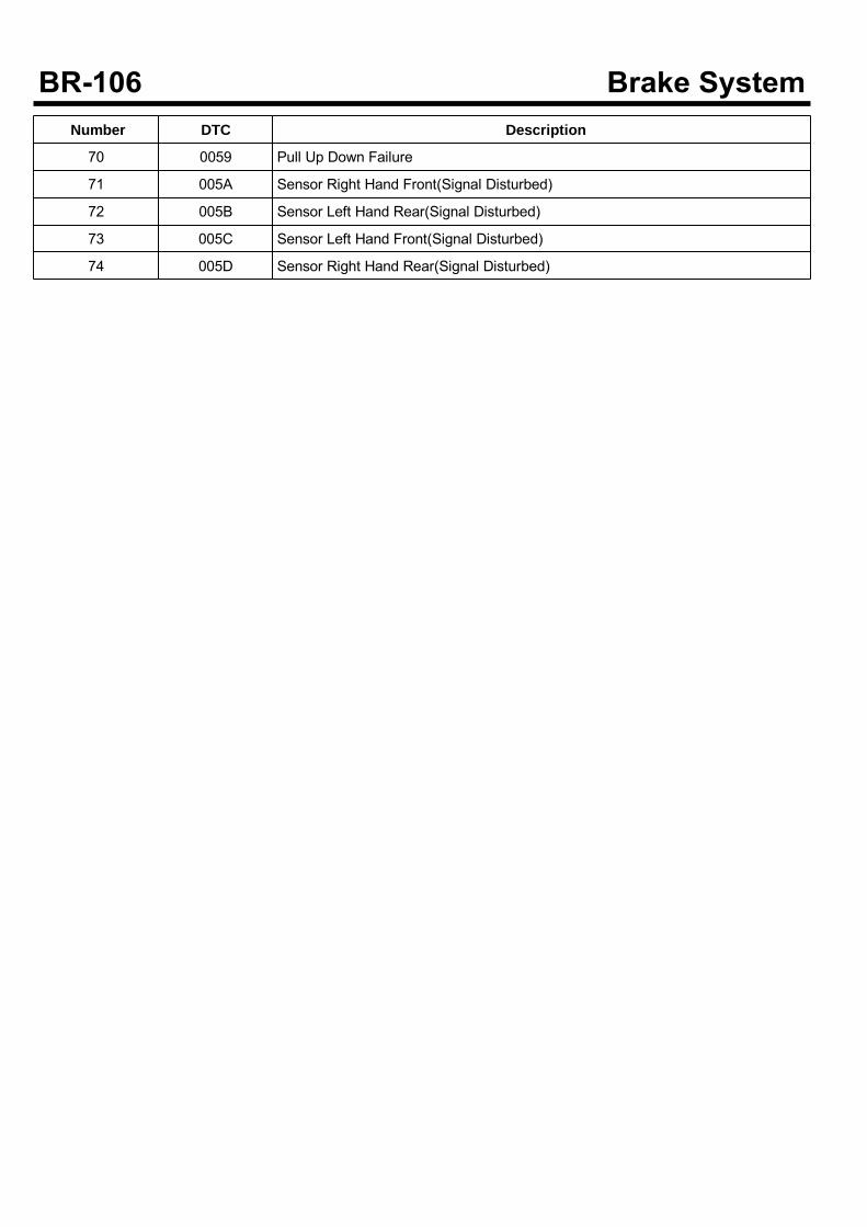
Number DTC Description
70 0059 Pull Up Down Failure
71 005A Sensor Right Hand Front(Signal Disturbed)
72 005B Sensor Left Hand Rear(Signal Disturbed)
73 005C Sensor Left Hand Front(Signal Disturbed)
74 005D Sensor Right Hand Rear(Signal Disturbed)

0000 Internal errorCOMPONENT LOCATION
SUDWAB9001L
GENERAL DESCRIPTIONThe Antilock Brake System (ABS) prevents the skidphenomenon that may occurs during a sudden brakewhile the vehicle is driving or when there is snow orwater on the road. By preventing the wheels from stickingor skidding on the road while the brake is applied, ABSmaintains the directional stability of the vehicle, securesthe steer ability, provides the maximum braking power soas to reduce the braking distance and to pursue theoverall safety of the driver and passengers. As the maindevice to perform ABS' braking function, HECU consistsof an input amplifier circuit that processes the inputsignal, an ABS control and SAFETY circuit thatcalculates the control and performs FAIL SAFE, anoutput circuit that drives the pressure control valve, avoltage adjustment circuit that regulates the voltage, anda failure memory circuit that memorizes anymalfunctioning. In case of a system malfunctioning, thewarning light is turned on, and at the same time, thepower to the pressure control valve is cut off, and theoperation of ABS is stopped.
DTC DESCRIPTIONHECU continues to monitor the internal components,such as memory, input and output circuits. In case of anerror during the operation of the control system, HECUdetermines whether it is a failure state and outputs a failcode.
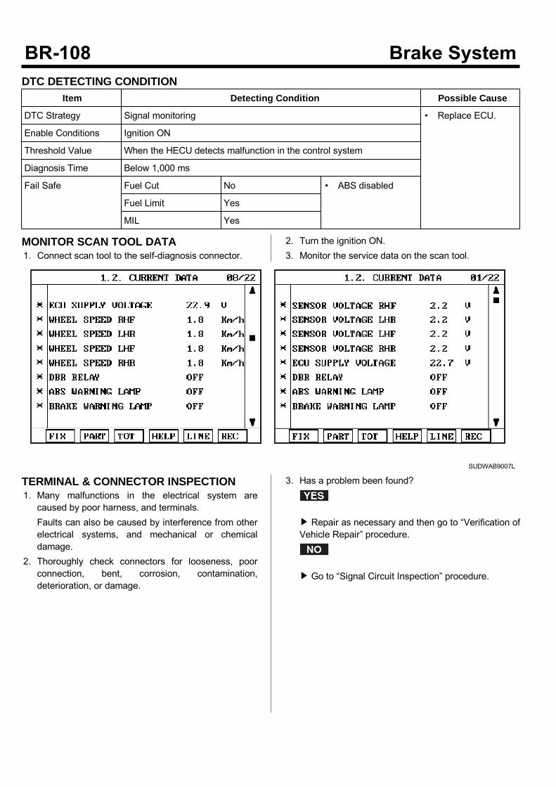
DTC DETECTING CONDITIONItem Detecting Condition Possible Cause
DTC Strategy Signal monitoring • Replace ECU.
Enable Conditions Ignition ON
Threshold Value When the HECU detects malfunction in the control system
Diagnosis Time Below 1,000 ms
Fail Safe Fuel Cut No • ABS disabled
Fuel Limit Yes
MIL Yes
MONITOR SCAN TOOL DATA1. Connect scan tool to the self-diagnosis connector.
2. Turn the ignition ON.3. Monitor the service data on the scan tool.
SUDWAB9007L
TERMINAL & CONNECTOR INSPECTION1. Many malfunctions in the electrical system arecaused by poor harness, and terminals.Faults can also be caused by interference from otherelectrical systems, and mechanical or chemicaldamage.
2. Thoroughly check connectors for looseness, poorconnection, bent, corrosion, contamination,deterioration, or damage.
3. Has a problem been found?
Repair as necessary and then go to “Verification ofVehicle Repair” procedure.
Go to “Signal Circuit Inspection” procedure.

COMPONENT INSPECTION1. Start the engine.2. Drive the vehicle with approx. 15km/h or higher.3. Turn the ignition ON. Leave the engine OFF.4. Connect the scan tool and check the diagnostictrouble codes by using self-diagnosis.
5. Using the scan tool erase the diagnostic troublecodes stored in the HECU.
6. Check that there are any diagnostic trouble codes byusing self-diagnosis with the scan tool.
7. Are any diagnostic trouble codes (DTCs) detected?
Check that the DTCs have disappeared afterreplacing with a known-good HECU. If the problemhas solved, we may guess the HECU is problem.Replace the HECU and go to “Verification of VehicleRepair” procedure.
There may be a defective valve component or atransient trouble due to a past trouble which did noterase the memory of HECU after having repair. Andgo to "Verification of Vehicle Repair” procedure.
VERIFICATION OF VEHICLE REPAIRAfter a repair, it is essential to verify that the fault hasbeen corrected.1. Connect the scan tool and perform the self diagnosis.Check diagnostic trouble codes.
2. Clear the diagnostic trouble codes (DTCs) stored inthe ECM by using the scan tool.
3. Drive the vehicle under conditions noted in failurerecords.
4. Check that there are any DTCs by performing selfdiagnosis with the scan tool.
5. Did the DTC return?
Go to the applicable DTC procedure.
System OK
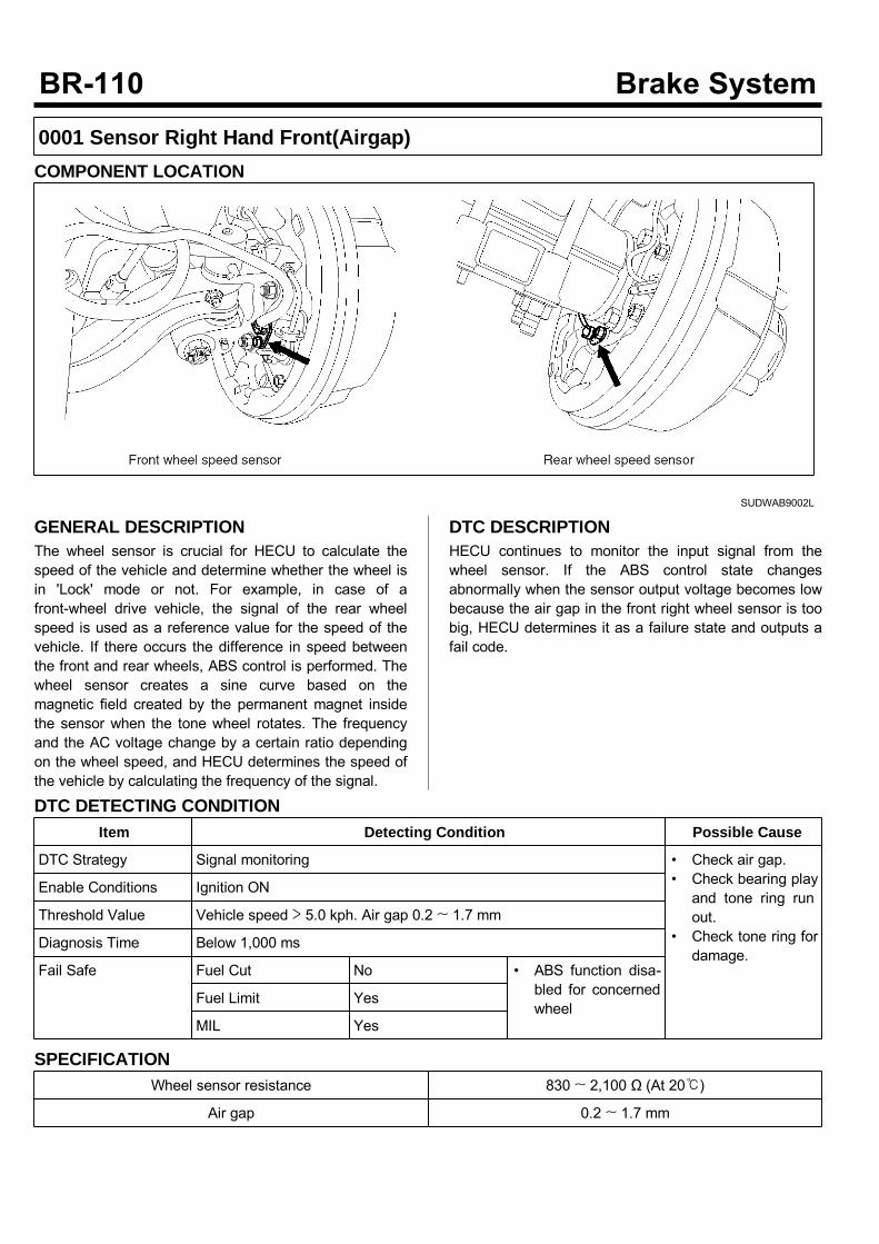
0001 Sensor Right Hand Front(Airgap)COMPONENT LOCATION
SUDWAB9002L
GENERAL DESCRIPTIONThe wheel sensor is crucial for HECU to calculate thespeed of the vehicle and determine whether the wheel isin 'Lock' mode or not. For example, in case of afront-wheel drive vehicle, the signal of the rear wheelspeed is used as a reference value for the speed of thevehicle. If there occurs the difference in speed betweenthe front and rear wheels, ABS control is performed. Thewheel sensor creates a sine curve based on themagnetic field created by the permanent magnet insidethe sensor when the tone wheel rotates. The frequencyand the AC voltage change by a certain ratio dependingon the wheel speed, and HECU determines the speed ofthe vehicle by calculating the frequency of the signal.
DTC DESCRIPTIONHECU continues to monitor the input signal from thewheel sensor. If the ABS control state changesabnormally when the sensor output voltage becomes lowbecause the air gap in the front right wheel sensor is toobig, HECU determines it as a failure state and outputs afail code.
DTC DETECTING CONDITIONItem Detecting Condition Possible Cause
DTC Strategy Signal monitoring • Check air gap.• Check bearing playand tone ring runout.
• Check tone ring fordamage.
Enable Conditions Ignition ON
Threshold Value Vehicle speed > 5.0 kph. Air gap 0.2 ~ 1.7 mm
Diagnosis Time Below 1,000 ms
Fail Safe Fuel Cut No • ABS function disa-bled for concernedwheel
Fuel Limit Yes
MIL Yes
SPECIFICATIONWheel sensor resistance 830 ~ 2,100 Ω (At 20)
Air gap 0.2 ~ 1.7 mm
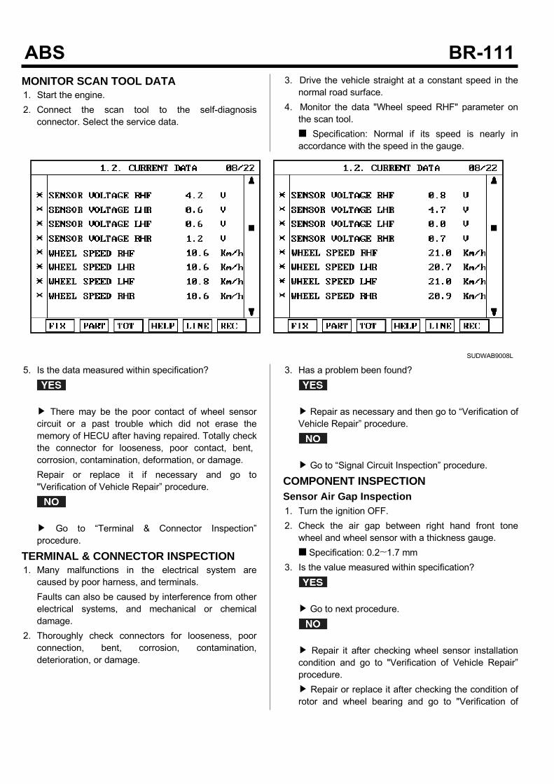
MONITOR SCAN TOOL DATA1. Start the engine.2. Connect the scan tool to the self-diagnosisconnector. Select the service data.
3. Drive the vehicle straight at a constant speed in thenormal road surface.
4. Monitor the data "Wheel speed RHF" parameter onthe scan tool. Specification: Normal if its speed is nearly inaccordance with the speed in the gauge.
SUDWAB9008L
5. Is the data measured within specification?
There may be the poor contact of wheel sensorcircuit or a past trouble which did not erase thememory of HECU after having repaired. Totally checkthe connector for looseness, poor contact, bent,corrosion, contamination, deformation, or damage.Repair or replace it if necessary and go to"Verification of Vehicle Repair” procedure.
Go to “Terminal & Connector Inspection”procedure.
TERMINAL & CONNECTOR INSPECTION1. Many malfunctions in the electrical system arecaused by poor harness, and terminals.Faults can also be caused by interference from otherelectrical systems, and mechanical or chemicaldamage.
2. Thoroughly check connectors for looseness, poorconnection, bent, corrosion, contamination,deterioration, or damage.
3. Has a problem been found?
Repair as necessary and then go to “Verification ofVehicle Repair” procedure.
Go to “Signal Circuit Inspection” procedure.
COMPONENT INSPECTIONSensor Air Gap Inspection1. Turn the ignition OFF.2. Check the air gap between right hand front tonewheel and wheel sensor with a thickness gauge. Specification: 0.2~1.7 mm
3. Is the value measured within specification?
Go to next procedure.
Repair it after checking wheel sensor installationcondition and go to "Verification of Vehicle Repair”procedure. Repair or replace it after checking the condition ofrotor and wheel bearing and go to "Verification of
Vehicle Repair” procedure. Adjust it after checking the air gap between wheelsensor and rotor and go to "Verification of VehicleRepair” procedure.
Right Hand Front Wheel Sensor Inspection1. Turn the ignition OFF.2. Disconnect the right hand front when sensorconnector.
3. Measure the resistance between positive (+) andnegative (-) of the right hand front wheel sensor(C30). Specification: 830 ~ 2,100 Ω (At 20)
4. Is the resistance measured within specification?
After checking the HECU for contamination ordamage, install a known-good HECU and check itgood or not. Replace the HECU if the vehicle is normalcondition and go to "Verification of Vehicle Repair”procedure.
Replace the sensor if the vehicle is normal aftertemporarily installing a known-good sensor and go to"Verification of Vehicle Repair” procedure.
VERIFICATION OF VEHICLE REPAIRAfter a repair, it is essential to verify that the fault hasbeen corrected.1. Connect the scan tool and perform the self diagnosis.Check diagnostic trouble codes.
2. Clear the diagnostic trouble codes (DTCs) stored inthe ECM by using the scan tool.
3. Drive the vehicle under conditions noted in failurerecords.
4. Check that there are any DTCs by performing selfdiagnosis with the scan tool.
5. Did the DTC return?
Go to the applicable DTC procedure.
System OK
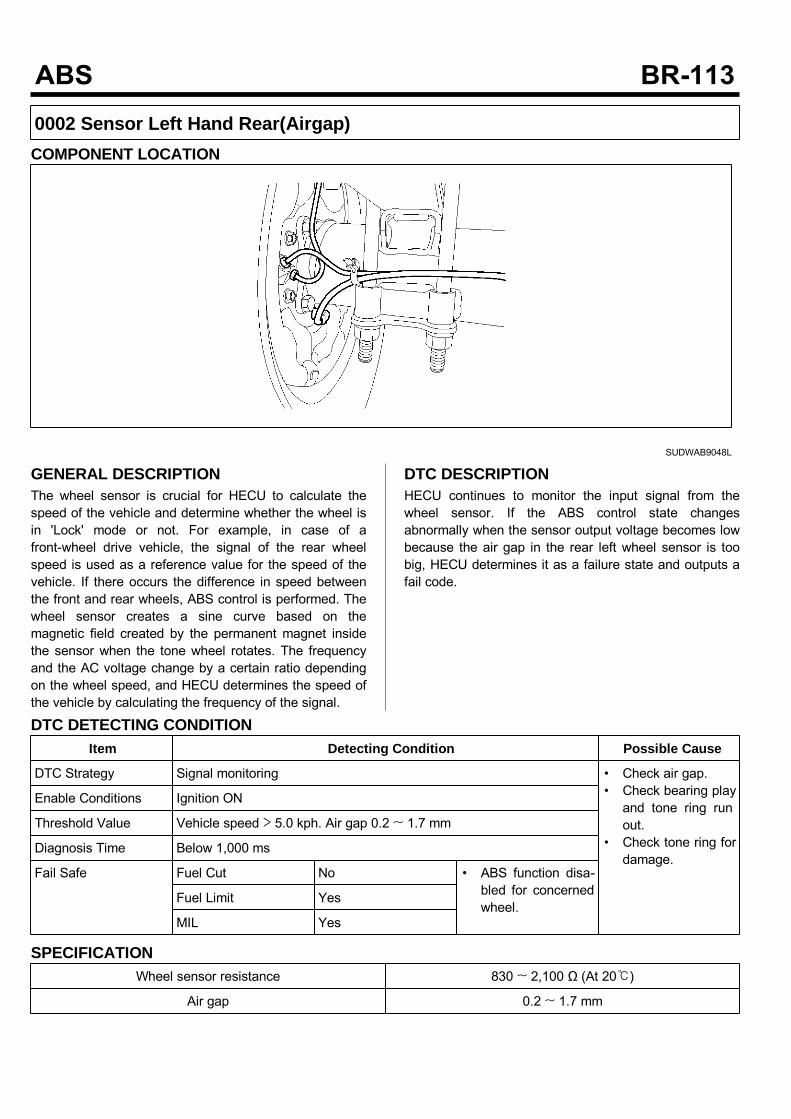
0002 Sensor Left Hand Rear(Airgap)COMPONENT LOCATION
SUDWAB9048L
GENERAL DESCRIPTIONThe wheel sensor is crucial for HECU to calculate thespeed of the vehicle and determine whether the wheel isin 'Lock' mode or not. For example, in case of afront-wheel drive vehicle, the signal of the rear wheelspeed is used as a reference value for the speed of thevehicle. If there occurs the difference in speed betweenthe front and rear wheels, ABS control is performed. Thewheel sensor creates a sine curve based on themagnetic field created by the permanent magnet insidethe sensor when the tone wheel rotates. The frequencyand the AC voltage change by a certain ratio dependingon the wheel speed, and HECU determines the speed ofthe vehicle by calculating the frequency of the signal.
DTC DESCRIPTIONHECU continues to monitor the input signal from thewheel sensor. If the ABS control state changesabnormally when the sensor output voltage becomes lowbecause the air gap in the rear left wheel sensor is toobig, HECU determines it as a failure state and outputs afail code.
DTC DETECTING CONDITIONItem Detecting Condition Possible Cause
DTC Strategy Signal monitoring • Check air gap.• Check bearing playand tone ring runout.
• Check tone ring fordamage.
Enable Conditions Ignition ON
Threshold Value Vehicle speed > 5.0 kph. Air gap 0.2 ~ 1.7 mm
Diagnosis Time Below 1,000 ms
Fail Safe Fuel Cut No • ABS function disa-bled for concernedwheel.
Fuel Limit Yes
MIL Yes
SPECIFICATIONWheel sensor resistance 830 ~ 2,100 Ω (At 20)
Air gap 0.2 ~ 1.7 mm
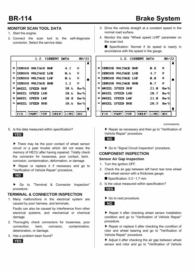
MONITOR SCAN TOOL DATA1. Start the engine.2. Connect the scan tool to the self-diagnosisconnector. Select the service data.
3. Drive the vehicle straight at a constant speed in thenormal road surface.
4. Monitor the data "Wheel speed LHR" parameter onthe scan tool. Specification: Normal if its speed is nearly inaccordance with the speed in the gauge.
SUDWAB9008L
5. Is the data measured within specification?
There may be the poor contact of wheel sensorcircuit or a past trouble which did not erase thememory of HECU after having repaired. Totally checkthe connector for looseness, poor contact, bent,corrosion, contamination, deformation, or damage. Repair or replace it if necessary and go to"Verification of Vehicle Repair” procedure.
Go to “Terminal & Connector Inspection”procedure.
TERMINAL & CONNECTOR INSPECTION1. Many malfunctions in the electrical system arecaused by poor harness, and terminals.Faults can also be caused by interference from otherelectrical systems, and mechanical or chemicaldamage.
2. Thoroughly check connectors for looseness, poorconnection, bent, corrosion, contamination,deterioration, or damage.
3. Has a problem been found?
Repair as necessary and then go to “Verification ofVehicle Repair” procedure.
Go to “Signal Circuit Inspection” procedure.
COMPONENT INSPECTIONSensor Air Gap Inspection1. Turn the ignition OFF.2. Check the air gap between left hand rear tone wheeland wheel sensor with a thickness gauge. Specification: 0.2~1.7 mm
3. Is the value measured within specification?
Go to next procedure.
Repair it after checking wheel sensor installationcondition and go to "Verification of Vehicle Repair”procedure. Repair or replace it after checking the condition ofrotor and wheel bearing and go to "Verification ofVehicle Repair” procedure. Adjust it after checking the air gap between wheelsensor and rotor and go to "Verification of Vehicle
Repair” procedure.Left Hand Rear Wheel Sensor Inspection1. Turn the ignition OFF.2. Disconnect the left hand rear connector (C37).3. Measure the resistance between terminal positive (+)and terminal negative (-) of the left hand rear wheelsensor (C37). Specification: 830 ~ 2100 Ω (At 20)
4. Is the resistance measured within specification?
After checking the HECU for contamination ordamage, install a known-good HECU and check itgood or not. Replace the HECU if the vehicle is normalcondition and go to "Verification of Vehicle Repair”procedure.
Replace the sensor if the vehicle is normal aftertemporarily installing a known-good sensor and go to"Verification of Vehicle Repair” procedure.
VERIFICATION OF VEHICLE REPAIRAfter a repair, it is essential to verify that the fault hasbeen corrected.1. Connect the scan tool and perform the self diagnosis.Check diagnostic trouble codes.
2. Clear the diagnostic trouble codes (DTCs) stored inthe ECM by using the scan tool.
3. Drive the vehicle under conditions noted in failurerecords.
4. Check that there are any DTCs by performing selfdiagnosis with the scan tool.
5. Did the DTC return?
Go to the applicable DTC procedure.
System OK
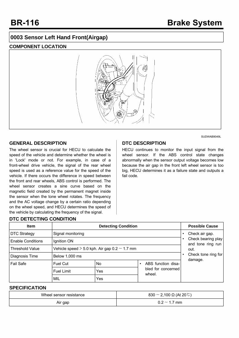
0003 Sensor Left Hand Front(Airgap)COMPONENT LOCATION
SUDWAB9049L
GENERAL DESCRIPTIONThe wheel sensor is crucial for HECU to calculate thespeed of the vehicle and determine whether the wheel isin 'Lock' mode or not. For example, in case of afront-wheel drive vehicle, the signal of the rear wheelspeed is used as a reference value for the speed of thevehicle. If there occurs the difference in speed betweenthe front and rear wheels, ABS control is performed. Thewheel sensor creates a sine curve based on themagnetic field created by the permanent magnet insidethe sensor when the tone wheel rotates. The frequencyand the AC voltage change by a certain ratio dependingon the wheel speed, and HECU determines the speed ofthe vehicle by calculating the frequency of the signal.
DTC DESCRIPTIONHECU continues to monitor the input signal from thewheel sensor. If the ABS control state changesabnormally when the sensor output voltage becomes lowbecause the air gap in the front left wheel sensor is toobig, HECU determines it as a failure state and outputs afail code.
DTC DETECTING CONDITIONItem Detecting Condition Possible Cause
DTC Strategy Signal monitoring • Check air gap.• Check bearing playand tone ring runout.
• Check tone ring fordamage.
Enable Conditions Ignition ON
Threshold Value Vehicle speed > 5.0 kph. Air gap 0.2 ~ 1.7 mm
Diagnosis Time Below 1,000 ms
Fail Safe Fuel Cut No • ABS function disa-bled for concernedwheel.
Fuel Limit Yes
MIL Yes
SPECIFICATIONWheel sensor resistance 830 ~ 2,100 Ω (At 20)
Air gap 0.2 ~ 1.7 mm
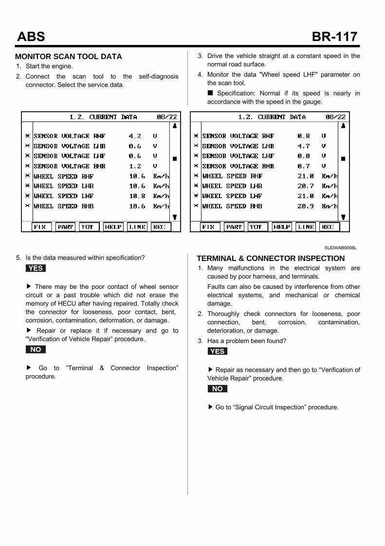
MONITOR SCAN TOOL DATA1. Start the engine.2. Connect the scan tool to the self-diagnosisconnector. Select the service data.
3. Drive the vehicle straight at a constant speed in thenormal road surface.
4. Monitor the data "Wheel speed LHF" parameter onthe scan tool. Specification: Normal if its speed is nearly inaccordance with the speed in the gauge.
SUDWAB9008L
5. Is the data measured within specification?
There may be the poor contact of wheel sensorcircuit or a past trouble which did not erase thememory of HECU after having repaired. Totally checkthe connector for looseness, poor contact, bent,corrosion, contamination, deformation, or damage. Repair or replace it if necessary and go to"Verification of Vehicle Repair” procedure.
Go to “Terminal & Connector Inspection”procedure.
TERMINAL & CONNECTOR INSPECTION1. Many malfunctions in the electrical system arecaused by poor harness, and terminals.Faults can also be caused by interference from otherelectrical systems, and mechanical or chemicaldamage.
2. Thoroughly check connectors for looseness, poorconnection, bent, corrosion, contamination,deterioration, or damage.
3. Has a problem been found?
Repair as necessary and then go to “Verification ofVehicle Repair” procedure.
Go to “Signal Circuit Inspection” procedure.

COMPONENT INSPECTIONLeft Hand Front Wheel Sensor Inspection1. Turn the ignition OFF.2. Disconnect the left hand front connector (C31).3. Measure the resistance between terminal positive (+)and terminal negative (-) of the left hand front wheelsensor. Specification: 830 ~ 2,100 Ω (At 20)
4. Is the resistance measured within specification?
After checking the HECU for contamination ordamage, install a known-good HECU and check itgood or not. Replace the HECU if the vehicle is normalcondition and go to "Verification of Vehicle Repair”procedure.
Replace the sensor if the vehicle is normal aftertemporarily installing a known-good sensor and go to"Verification of Vehicle Repair” procedure.
VERIFICATION OF VEHICLE REPAIRAfter a repair, it is essential to verify that the fault hasbeen corrected.1. Connect the scan tool and perform the self diagnosis.Check diagnostic trouble codes.
2. Clear the diagnostic trouble codes (DTCs) stored inthe ECM by using the scan tool.
3. Drive the vehicle under conditions noted in failurerecords.
4. Check that there are any DTCs by performing selfdiagnosis with the scan tool.
5. Did the DTC return?
Go to the applicable DTC procedure.
System OK
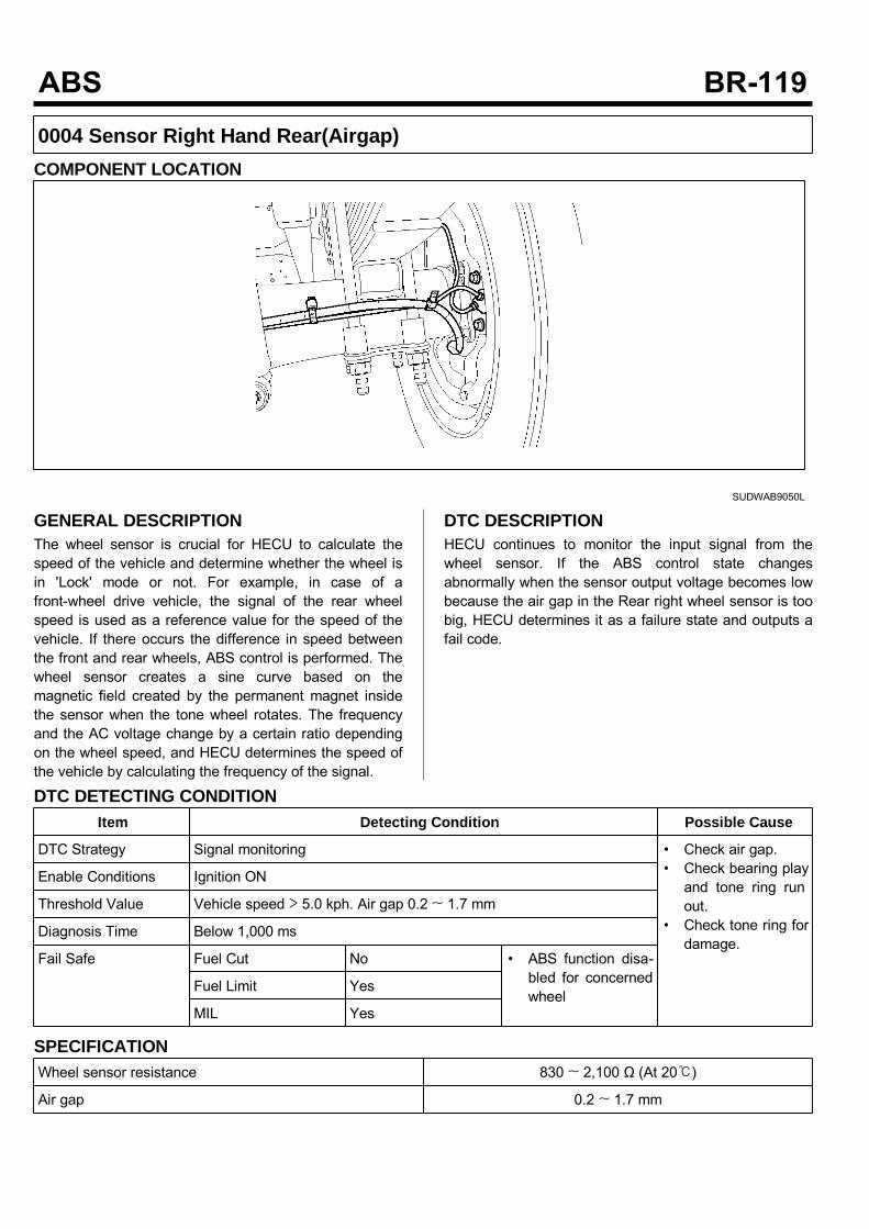
0004 Sensor Right Hand Rear(Airgap)COMPONENT LOCATION
SUDWAB9050L
GENERAL DESCRIPTIONThe wheel sensor is crucial for HECU to calculate thespeed of the vehicle and determine whether the wheel isin 'Lock' mode or not. For example, in case of afront-wheel drive vehicle, the signal of the rear wheelspeed is used as a reference value for the speed of thevehicle. If there occurs the difference in speed betweenthe front and rear wheels, ABS control is performed. Thewheel sensor creates a sine curve based on themagnetic field created by the permanent magnet insidethe sensor when the tone wheel rotates. The frequencyand the AC voltage change by a certain ratio dependingon the wheel speed, and HECU determines the speed ofthe vehicle by calculating the frequency of the signal.
DTC DESCRIPTIONHECU continues to monitor the input signal from thewheel sensor. If the ABS control state changesabnormally when the sensor output voltage becomes lowbecause the air gap in the Rear right wheel sensor is toobig, HECU determines it as a failure state and outputs afail code.
DTC DETECTING CONDITIONItem Detecting Condition Possible Cause
DTC Strategy Signal monitoring • Check air gap.• Check bearing playand tone ring runout.
• Check tone ring fordamage.
Enable Conditions Ignition ON
Threshold Value Vehicle speed > 5.0 kph. Air gap 0.2 ~ 1.7 mm
Diagnosis Time Below 1,000 ms
Fail Safe Fuel Cut No • ABS function disa-bled for concernedwheel
Fuel Limit Yes
MIL Yes
SPECIFICATIONWheel sensor resistance 830 ~ 2,100 Ω (At 20)
Air gap 0.2 ~ 1.7 mm
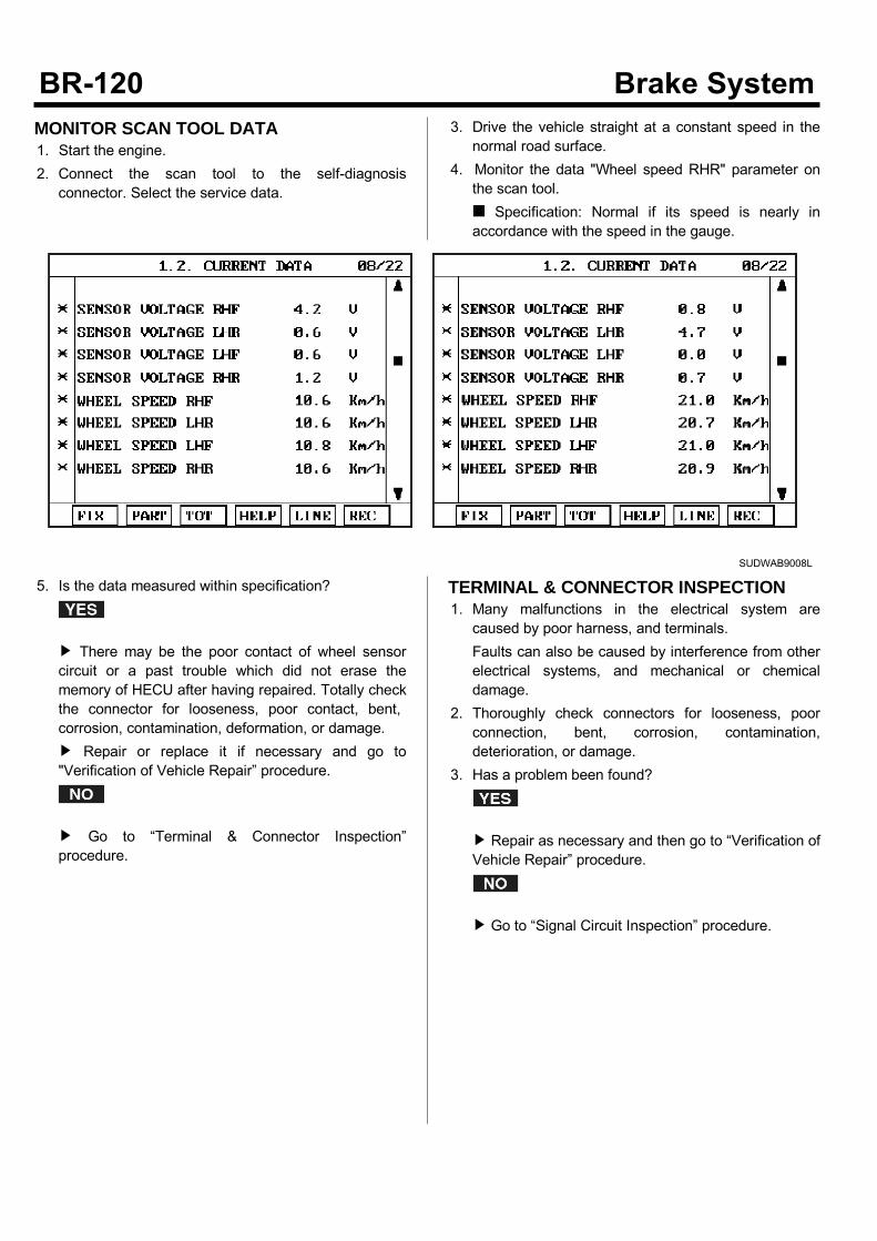
MONITOR SCAN TOOL DATA1. Start the engine.2. Connect the scan tool to the self-diagnosisconnector. Select the service data.
3. Drive the vehicle straight at a constant speed in thenormal road surface.
4. Monitor the data "Wheel speed RHR" parameter onthe scan tool. Specification: Normal if its speed is nearly inaccordance with the speed in the gauge.
SUDWAB9008L
5. Is the data measured within specification?
There may be the poor contact of wheel sensorcircuit or a past trouble which did not erase thememory of HECU after having repaired. Totally checkthe connector for looseness, poor contact, bent,corrosion, contamination, deformation, or damage. Repair or replace it if necessary and go to"Verification of Vehicle Repair” procedure.
Go to “Terminal & Connector Inspection”procedure.
TERMINAL & CONNECTOR INSPECTION1. Many malfunctions in the electrical system arecaused by poor harness, and terminals.Faults can also be caused by interference from otherelectrical systems, and mechanical or chemicaldamage.
2. Thoroughly check connectors for looseness, poorconnection, bent, corrosion, contamination,deterioration, or damage.
3. Has a problem been found?
Repair as necessary and then go to “Verification ofVehicle Repair” procedure.
Go to “Signal Circuit Inspection” procedure.
COMPONENT INSPECTIONRight hand rear Wheel Sensor Inspection1. Turn the ignition OFF.2. Disconnect the right hand rear connector (C36).3. Measure the resistance between terminal positive (+)and terminal negative (-) of the right hand rear wheelsensor (C36). Specification: 830 ~ 2100 Ω (At 20)
4. Is the resistance measured within specification?
After checking the HECU for contamination ordamage, install a known-good HECU and check itgood or not. Replace the HECU if the vehicle is normalcondition and go to "Verification of Vehicle Repair”procedure.
Replace the sensor if the vehicle is normal aftertemporarily installing a known-good sensor and go to"Verification of Vehicle Repair” procedure.
VERIFICATION OF VEHICLE REPAIRAfter a repair, it is essential to verify that the fault hasbeen corrected.1. Connect the scan tool and perform the self diagnosis.Check diagnostic trouble codes.
2. Clear the diagnostic trouble codes (DTCs) stored inthe ECM by using the scan tool.
3. Drive the vehicle under conditions noted in failurerecords.
4. Check that there are any DTCs by performing selfdiagnosis with the scan tool.
5. Did the DTC return?
Go to the applicable DTC procedure.
System OK

0009 Input Valve Right Hand Front(Short To Ubatt/Uvent)COMPONENT LOCATION
SUDWAB9002L
GENERAL DESCRIPTIONThe Antilock Brake System (ABS) prevents the skidphenomenon that may occurs during a sudden brakewhile the vehicle is driving or when there is snow orwater on the road. By preventing the wheels from stickingor skidding on the road while the brake is applied, ABSmaintains the directional stability of the vehicle, securesthe steer ability, provides the maximum braking power soas to reduce the braking distance and to pursue theoverall safety of the driver and passengers. As the maindevice to perform ABS' braking function, HECU consistsof an input amplifier circuit that processes the inputsignal, an ABS control and SAFETY circuit thatcalculates the control and performs FAIL SAFE, anoutput circuit that drives the pressure control valve, avoltage adjustment circuit that regulates the voltage, anda failure memory circuit that memorizes anymalfunctioning. In case of a system malfunctioning, thewarning light is turned on, and at the same time, thepower to the pressure control valve is cut off, and theoperation of ABS is stopped.
DTC DESCRIPTIONHECU continues to monitor the internal components,such as memory, input and output circuits. In case of anerror during the operation of the control system, HECUdetermines whether it is a failure state and outputs a failcode.

DTC DETECTING CONDITIONItem Detecting Condition Possible Cause
DTC Strategy Signal monitoring • Replace ECU.
Enable Conditions Ignition ON
Threshold Value When the HECU detects malfunction in the control system
Diagnosis Time Below 1,000 ms
Fail Safe Fuel Cut No • ABS disabled
Fuel Limit Yes
MIL Yes
MONITOR SCAN TOOL DATA1. Connect the scan tool to the self-diagnosisconnector.
2. Turn the ignition ON.3. Select the data "Actuation test"
4. Check the right hand front inlet valve for operationwhen activating the actuator. Specification: Normal if the activating sound isheard.
SUDWAB9009L
Fig1) Right hand front inlet valve Actuation test at IGON
5. Does the valve activate normally?
There may be a transient trouble due to defectivevalve or a past trouble which did not erase thememory of HECU after having repair. And go to "Verification of Vehicle Repair”procedure.
Go to "Component Inspection" procedure.
TERMINAL & CONNECTOR INSPECTION1. Many malfunctions in the electrical system arecaused by poor harness, and terminals.Faults can also be caused by interference from otherelectrical systems, and mechanical or chemicaldamage.
2. Thoroughly check connectors for looseness, poorconnection, bent, corrosion, contamination,deterioration, or damage.
3. Has a problem been found?
Repair as necessary and then go to “Verification ofVehicle Repair” procedure.

Go to “Signal Circuit Inspection” procedure.
COMPONENT INSPECTION1. Start the engine.2. Drive the vehicle with approx. 15km/h or higher.3. Turn the ignition ON. Leave the engine OFF.4. Connect the scan tool and check the diagnostictrouble codes by using self-diagnosis.
5. Using the scan tool erase the diagnostic troublecodes stored in the HECU.
6. Check that there are any diagnostic trouble codes byusing self-diagnosis with the scan tool.
7. Are any diagnostic trouble codes (DTCs) detected?
Check that the DTCs have disappeared afterreplacing with a known-good HECU. If the problemhas solved, we may guess the HECU is problem.Replace the HECU and go to “Verification of VehicleRepair” procedure.
There may be a defective valve component or atransient trouble due to a past trouble which did noterase the memory of HECU after having repair. Andgo to "Verification of Vehicle Repair” procedure.
VERIFICATION OF VEHICLE REPAIRAfter a repair, it is essential to verify that the fault hasbeen corrected.1. Connect the scan tool and perform the self diagnosis.Check diagnostic trouble codes.
2. Clear the diagnostic trouble codes (DTCs) stored inthe ECM by using the scan tool.
3. Drive the vehicle under conditions noted in failurerecords.
4. Check that there are any DTCs by performing selfdiagnosis with the scan tool.
5. Did the DTC return?
Go to the applicable DTC procedure.
System OK
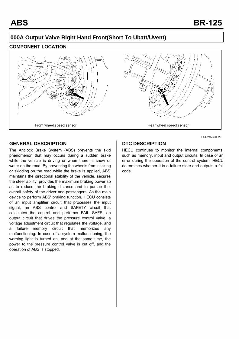
000A Output Valve Right Hand Front(Short To Ubatt/Uvent)COMPONENT LOCATION
SUDWAB9002L
GENERAL DESCRIPTIONThe Antilock Brake System (ABS) prevents the skidphenomenon that may occurs during a sudden brakewhile the vehicle is driving or when there is snow orwater on the road. By preventing the wheels from stickingor skidding on the road while the brake is applied, ABSmaintains the directional stability of the vehicle, securesthe steer ability, provides the maximum braking power soas to reduce the braking distance and to pursue theoverall safety of the driver and passengers. As the maindevice to perform ABS' braking function, HECU consistsof an input amplifier circuit that processes the inputsignal, an ABS control and SAFETY circuit thatcalculates the control and performs FAIL SAFE, anoutput circuit that drives the pressure control valve, avoltage adjustment circuit that regulates the voltage, anda failure memory circuit that memorizes anymalfunctioning. In case of a system malfunctioning, thewarning light is turned on, and at the same time, thepower to the pressure control valve is cut off, and theoperation of ABS is stopped.
DTC DESCRIPTIONHECU continues to monitor the internal components,such as memory, input and output circuits. In case of anerror during the operation of the control system, HECUdetermines whether it is a failure state and outputs a failcode.
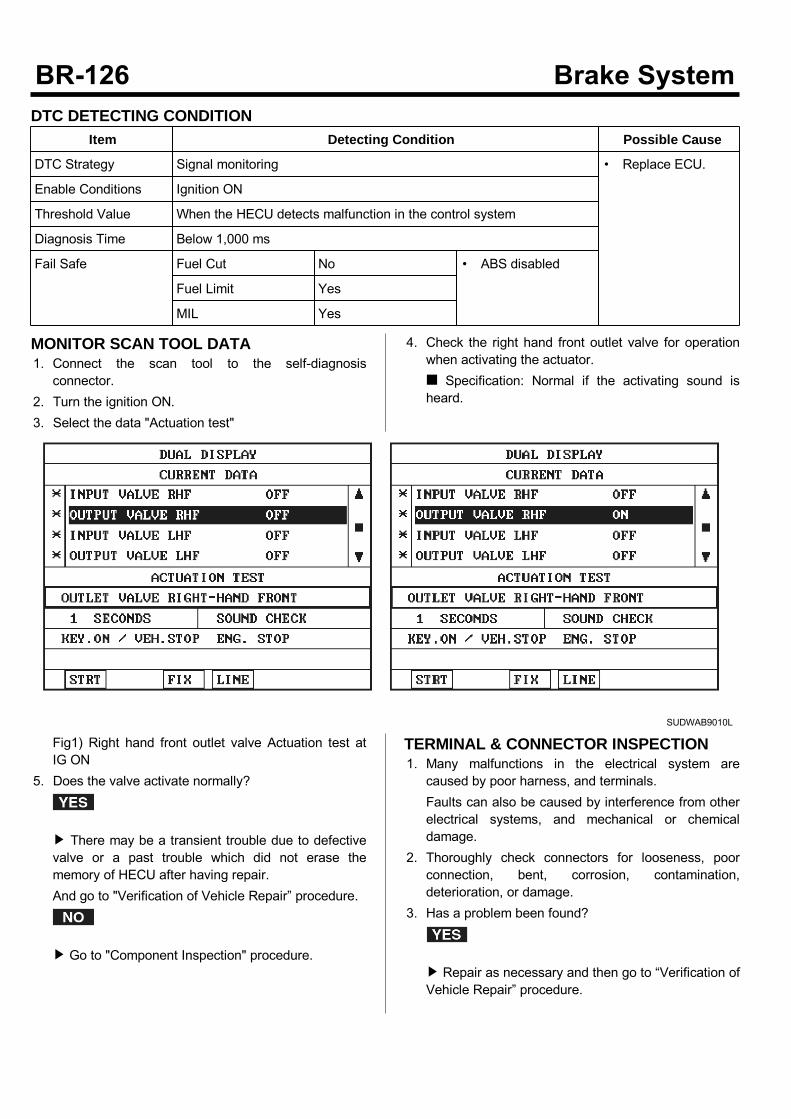
DTC DETECTING CONDITIONItem Detecting Condition Possible Cause
DTC Strategy Signal monitoring • Replace ECU.
Enable Conditions Ignition ON
Threshold Value When the HECU detects malfunction in the control system
Diagnosis Time Below 1,000 ms
Fail Safe Fuel Cut No • ABS disabled
Fuel Limit Yes
MIL Yes
MONITOR SCAN TOOL DATA1. Connect the scan tool to the self-diagnosisconnector.
2. Turn the ignition ON.3. Select the data "Actuation test"
4. Check the right hand front outlet valve for operationwhen activating the actuator. Specification: Normal if the activating sound isheard.
SUDWAB9010L
Fig1) Right hand front outlet valve Actuation test atIG ON
5. Does the valve activate normally?
There may be a transient trouble due to defectivevalve or a past trouble which did not erase thememory of HECU after having repair.And go to "Verification of Vehicle Repair” procedure.
Go to "Component Inspection" procedure.
TERMINAL & CONNECTOR INSPECTION1. Many malfunctions in the electrical system arecaused by poor harness, and terminals.Faults can also be caused by interference from otherelectrical systems, and mechanical or chemicaldamage.
2. Thoroughly check connectors for looseness, poorconnection, bent, corrosion, contamination,deterioration, or damage.
3. Has a problem been found?
Repair as necessary and then go to “Verification ofVehicle Repair” procedure.

Go to “Signal Circuit Inspection” procedure.
COMPONENT INSPECTION1. Start the engine.2. Drive the vehicle with approx. 15km/h or higher.3. Turn the ignition ON. Leave the engine OFF.4. Connect the scan tool and check the diagnostictrouble codes by using self-diagnosis.
5. Using the scan tool erase the diagnostic troublecodes stored in the HECU.
6. Check that there are any diagnostic trouble codes byusing self-diagnosis with the scan tool.
7. Are any diagnostic trouble codes (DTCs) detected?
Check that the DTCs have disappeared afterreplacing with a known-good HECU. If the problemhas solved, we may guess the HECU is problem.Replace the HECU and go to “Verification of VehicleRepair” procedure.
There may be a defective valve component or atransient trouble due to a past trouble which did noterase the memory of HECU after having repair. Andgo to "Verification of Vehicle Repair” procedure.
VERIFICATION OF VEHICLE REPAIRAfter a repair, it is essential to verify that the fault hasbeen corrected.1. Connect the scan tool and perform the self diagnosis.Check diagnostic trouble codes.
2. Clear the diagnostic trouble codes (DTCs) stored inthe ECM by using the scan tool.
3. Drive the vehicle under conditions noted in failurerecords.
4. Check that there are any DTCs by performing selfdiagnosis with the scan tool.
5. Did the DTC return?
Go to the applicable DTC procedure.
System OK
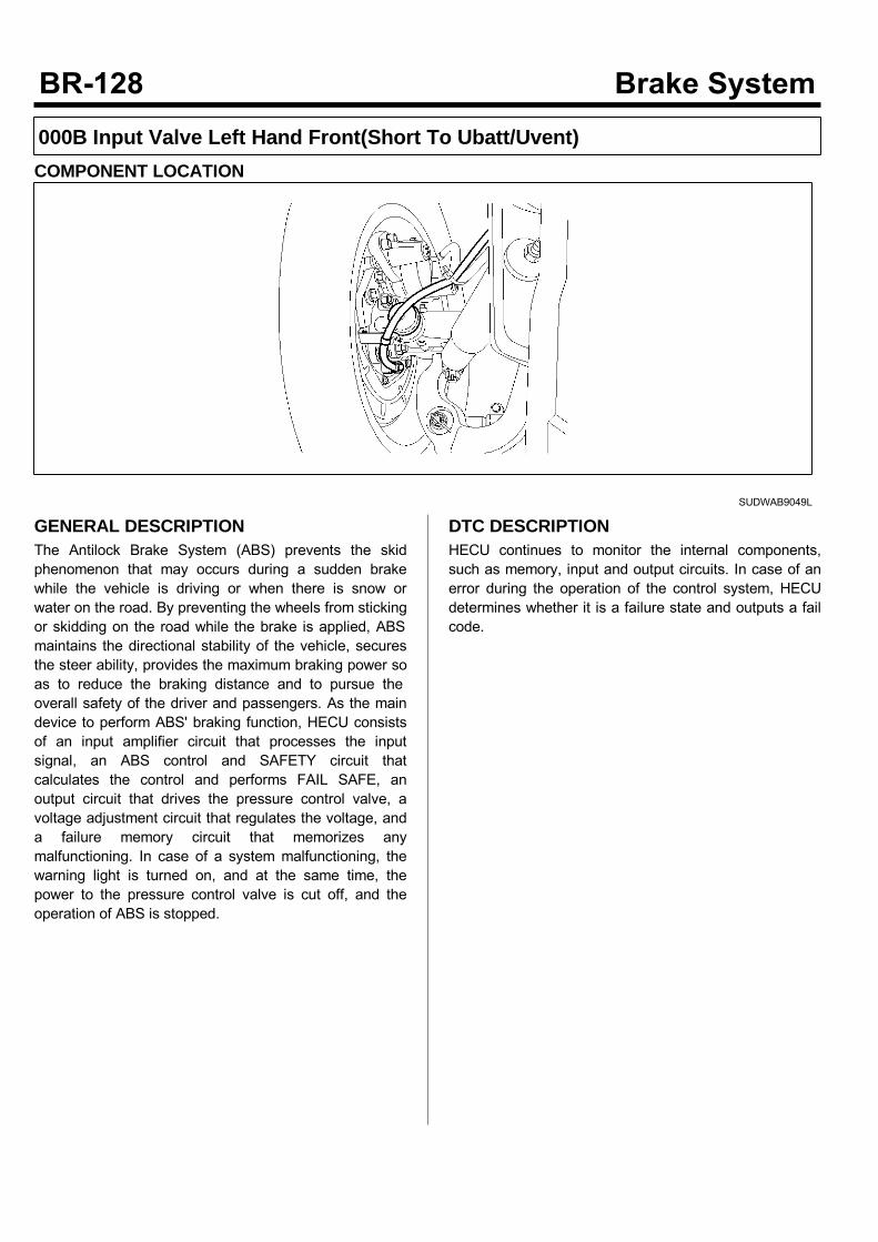
000B Input Valve Left Hand Front(Short To Ubatt/Uvent)COMPONENT LOCATION
SUDWAB9049L
GENERAL DESCRIPTIONThe Antilock Brake System (ABS) prevents the skidphenomenon that may occurs during a sudden brakewhile the vehicle is driving or when there is snow orwater on the road. By preventing the wheels from stickingor skidding on the road while the brake is applied, ABSmaintains the directional stability of the vehicle, securesthe steer ability, provides the maximum braking power soas to reduce the braking distance and to pursue theoverall safety of the driver and passengers. As the maindevice to perform ABS' braking function, HECU consistsof an input amplifier circuit that processes the inputsignal, an ABS control and SAFETY circuit thatcalculates the control and performs FAIL SAFE, anoutput circuit that drives the pressure control valve, avoltage adjustment circuit that regulates the voltage, anda failure memory circuit that memorizes anymalfunctioning. In case of a system malfunctioning, thewarning light is turned on, and at the same time, thepower to the pressure control valve is cut off, and theoperation of ABS is stopped.
DTC DESCRIPTIONHECU continues to monitor the internal components,such as memory, input and output circuits. In case of anerror during the operation of the control system, HECUdetermines whether it is a failure state and outputs a failcode.
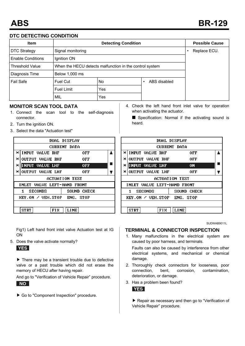
DTC DETECTING CONDITIONItem Detecting Condition Possible Cause
DTC Strategy Signal monitoring • Replace ECU.
Enable Conditions Ignition ON
Threshold Value When the HECU detects malfunction in the control system
Diagnosis Time Below 1,000 ms
Fail Safe Fuel Cut No • ABS disabled
Fuel Limit Yes
MIL Yes
MONITOR SCAN TOOL DATA1. Connect the scan tool to the self-diagnosisconnector.
2. Turn the ignition ON.3. Select the data "Actuation test"
4. Check the left hand front inlet valve for operationwhen activating the actuator. Specification: Normal if the activating sound isheard.
SUDWAB9011L
Fig1) Left hand front inlet valve Actuation test at IGON
5. Does the valve activate normally?
There may be a transient trouble due to defectivevalve or a past trouble which did not erase thememory of HECU after having repair.And go to "Verification of Vehicle Repair” procedure.
Go to "Component Inspection" procedure.
TERMINAL & CONNECTOR INSPECTION1. Many malfunctions in the electrical system arecaused by poor harness, and terminals.Faults can also be caused by interference from otherelectrical systems, and mechanical or chemicaldamage.
2. Thoroughly check connectors for looseness, poorconnection, bent, corrosion, contamination,deterioration, or damage.
3. Has a problem been found?
Repair as necessary and then go to “Verification ofVehicle Repair” procedure.

Go to “Signal Circuit Inspection” procedure.
COMPONENT INSPECTION1. Start the engine.2. Drive the vehicle with approx. 15km/h or higher.3. Turn the ignition ON. Leave the engine OFF.4. Connect the scan tool and check the diagnostictrouble codes by using self-diagnosis.
5. Using the scan tool erase the diagnostic troublecodes stored in the HECU.
6. Check that there are any diagnostic trouble codes byusing self-diagnosis with the scan tool.
7. Are any diagnostic trouble codes (DTCs) detected?
Check that the DTCs have disappeared afterreplacing with a known-good HECU. If the problemhas solved, we may guess the HECU is problem.Replace the HECU and go to “Verification of VehicleRepair” procedure.
There may be a defective valve component or atransient trouble due to a past trouble which did noterase the memory of HECU after having repair. Andgo to "Verification of Vehicle Repair” procedure.
VERIFICATION OF VEHICLE REPAIRAfter a repair, it is essential to verify that the fault hasbeen corrected.1. Connect the scan tool and perform the self diagnosis.Check diagnostic trouble codes.
2. Clear the diagnostic trouble codes (DTCs) stored inthe ECM by using the scan tool.
3. Drive the vehicle under conditions noted in failurerecords.
4. Check that there are any DTCs by performing selfdiagnosis with the scan tool.
5. Did the DTC return?
Go to the applicable DTC procedure.
System OK
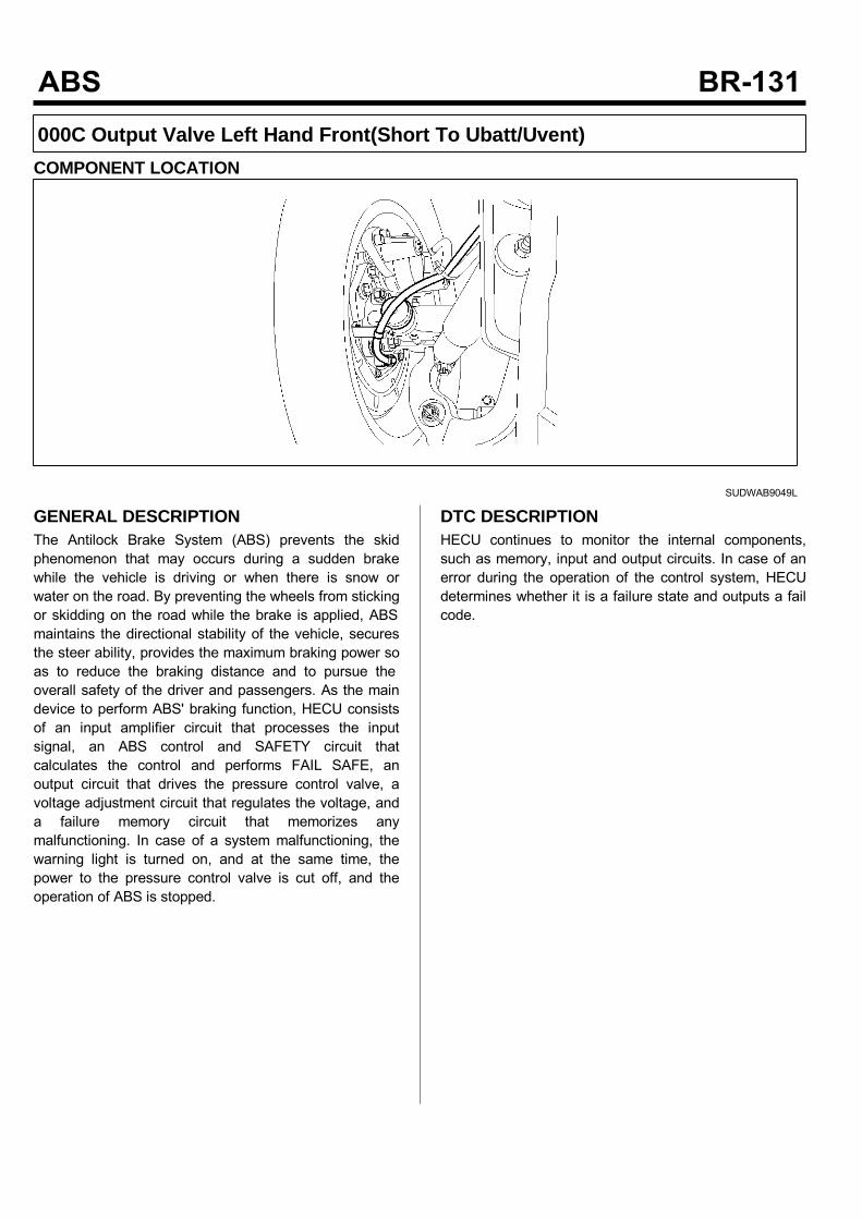
000C Output Valve Left Hand Front(Short To Ubatt/Uvent)COMPONENT LOCATION
SUDWAB9049L
GENERAL DESCRIPTIONThe Antilock Brake System (ABS) prevents the skidphenomenon that may occurs during a sudden brakewhile the vehicle is driving or when there is snow orwater on the road. By preventing the wheels from stickingor skidding on the road while the brake is applied, ABSmaintains the directional stability of the vehicle, securesthe steer ability, provides the maximum braking power soas to reduce the braking distance and to pursue theoverall safety of the driver and passengers. As the maindevice to perform ABS' braking function, HECU consistsof an input amplifier circuit that processes the inputsignal, an ABS control and SAFETY circuit thatcalculates the control and performs FAIL SAFE, anoutput circuit that drives the pressure control valve, avoltage adjustment circuit that regulates the voltage, anda failure memory circuit that memorizes anymalfunctioning. In case of a system malfunctioning, thewarning light is turned on, and at the same time, thepower to the pressure control valve is cut off, and theoperation of ABS is stopped.
DTC DESCRIPTIONHECU continues to monitor the internal components,such as memory, input and output circuits. In case of anerror during the operation of the control system, HECUdetermines whether it is a failure state and outputs a failcode.
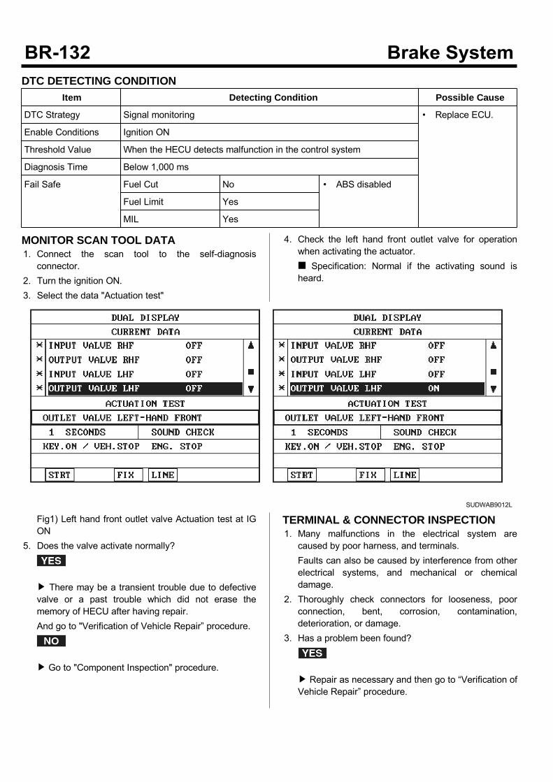
DTC DETECTING CONDITIONItem Detecting Condition Possible Cause
DTC Strategy Signal monitoring • Replace ECU.
Enable Conditions Ignition ON
Threshold Value When the HECU detects malfunction in the control system
Diagnosis Time Below 1,000 ms
Fail Safe Fuel Cut No • ABS disabled
Fuel Limit Yes
MIL Yes
MONITOR SCAN TOOL DATA1. Connect the scan tool to the self-diagnosisconnector.
2. Turn the ignition ON.3. Select the data "Actuation test"
4. Check the left hand front outlet valve for operationwhen activating the actuator. Specification: Normal if the activating sound isheard.
SUDWAB9012L
Fig1) Left hand front outlet valve Actuation test at IGON
5. Does the valve activate normally?
There may be a transient trouble due to defectivevalve or a past trouble which did not erase thememory of HECU after having repair.And go to "Verification of Vehicle Repair” procedure.
Go to "Component Inspection" procedure.
TERMINAL & CONNECTOR INSPECTION1. Many malfunctions in the electrical system arecaused by poor harness, and terminals.Faults can also be caused by interference from otherelectrical systems, and mechanical or chemicaldamage.
2. Thoroughly check connectors for looseness, poorconnection, bent, corrosion, contamination,deterioration, or damage.
3. Has a problem been found?
Repair as necessary and then go to “Verification ofVehicle Repair” procedure.

Go to “Signal Circuit Inspection” procedure.
COMPONENT INSPECTION1. Start the engine.2. Drive the vehicle with approx. 15km/h or higher.3. Turn the ignition ON. Leave the engine OFF.4. Connect the scan tool and check the diagnostictrouble codes by using self-diagnosis.
5. Using the scan tool erase the diagnostic troublecodes stored in the HECU.
6. Check that there are any diagnostic trouble codes byusing self-diagnosis with the scan tool.
7. Are any diagnostic trouble codes (DTCs) detected?
Check that the DTCs have disappeared afterreplacing with a known-good HECU. If the problemhas solved, we may guess the HECU is problem.Replace the HECU and go to “Verification of VehicleRepair” procedure.
There may be a defective valve component or atransient trouble due to a past trouble which did noterase the memory of HECU after having repair. Andgo to "Verification of Vehicle Repair” procedure.
VERIFICATION OF VEHICLE REPAIRAfter a repair, it is essential to verify that the fault hasbeen corrected.1. Connect the scan tool and perform the self diagnosis.Check diagnostic trouble codes.
2. Clear the diagnostic trouble codes (DTCs) stored inthe ECM by using the scan tool.
3. Drive the vehicle under conditions noted in failurerecords.
4. Check that there are any DTCs by performing selfdiagnosis with the scan tool.
5. Did the DTC return?
Go to the applicable DTC procedure.
System OK

000D Input Valve Right Hand Rear(Short To Ubatt/Uvent)COMPONENT LOCATION
SUDWAB9050L
GENERAL DESCRIPTIONThe Antilock Brake System (ABS) prevents the skidphenomenon that may occurs during a sudden brakewhile the vehicle is driving or when there is snow orwater on the road. By preventing the wheels from stickingor skidding on the road while the brake is applied, ABSmaintains the directional stability of the vehicle, securesthe steer ability, provides the maximum braking power soas to reduce the braking distance and to pursue theoverall safety of the driver and passengers. As the maindevice to perform ABS' braking function, HECU consistsof an input amplifier circuit that processes the inputsignal, an ABS control and SAFETY circuit thatcalculates the control and performs FAIL SAFE, anoutput circuit that drives the pressure control valve, avoltage adjustment circuit that regulates the voltage, anda failure memory circuit that memorizes anymalfunctioning. In case of a system malfunctioning, thewarning light is turned on, and at the same time, thepower to the pressure control valve is cut off, and theoperation of ABS is stopped.
DTC DESCRIPTIONHECU continues to monitor the internal components,such as memory, input and output circuits. In case of anerror during the operation of the control system, HECUdetermines whether it is a failure state and outputs a failcode.

DTC DETECTING CONDITIONItem Detecting Condition Possible Cause
DTC Strategy Signal monitoring • Replace ECU.
Enable Conditions Ignition ON
Threshold Value When the HECU detects malfunction in the control system
Diagnosis Time Below 1,000 ms
Fail Safe Fuel Cut No • ABS disabled
Fuel Limit Yes
MIL Yes
MONITOR SCAN TOOL DATA1. Connect the scan tool to the self-diagnosisconnector.
2. Turn the ignition ON.3. Select the data "Actuation test"
4. Check the right hand rear inlet valve for operationwhen activating the actuator. Specification: Normal if the activating sound isheard.
SUDWAB9013L
Fig1) Right hand rear inlet valve Actuation test at IGON
5. Does the valve activate normally?
There may be a transient trouble due to defectivevalve or a past trouble which did not erase thememory of HECU after having repair.And go to "Verification of Vehicle Repair” procedure.
Go to "Component Inspection" procedure.
TERMINAL & CONNECTOR INSPECTION1. Many malfunctions in the electrical system arecaused by poor harness, and terminals.Faults can also be caused by interference from otherelectrical systems, and mechanical or chemicaldamage.
2. Thoroughly check connectors for looseness, poorconnection, bent, corrosion, contamination,deterioration, or damage.
3. Has a problem been found?
Repair as necessary and then go to “Verification ofVehicle Repair” procedure.

Go to “Signal Circuit Inspection” procedure.
COMPONENT INSPECTION1. Start the engine.2. Drive the vehicle with approx. 15km/h or higher.3. Turn the ignition ON. Leave the engine OFF.4. Connect the scan tool and check the diagnostictrouble codes by using self-diagnosis.
5. Using the scan tool erase the diagnostic troublecodes stored in the HECU.
6. Check that there are any diagnostic trouble codes byusing self-diagnosis with the scan tool.
7. Are any diagnostic trouble codes (DTCs) detected?
Check that the DTCs have disappeared afterreplacing with a known-good HECU. If the problemhas solved, we may guess the HECU is problem.Replace the HECU and go to “Verification of VehicleRepair” procedure.
There may be a defective valve component or atransient trouble due to a past trouble which did noterase the memory of HECU after having repair. Andgo to "Verification of Vehicle Repair” procedure.
VERIFICATION OF VEHICLE REPAIRAfter a repair, it is essential to verify that the fault hasbeen corrected.1. Connect the scan tool and perform the self diagnosis.Check diagnostic trouble codes.
2. Clear the diagnostic trouble codes (DTCs) stored inthe ECM by using the scan tool.
3. Drive the vehicle under conditions noted in failurerecords.
4. Check that there are any DTCs by performing selfdiagnosis with the scan tool.
5. Did the DTC return?
Go to the applicable DTC procedure.
System OK
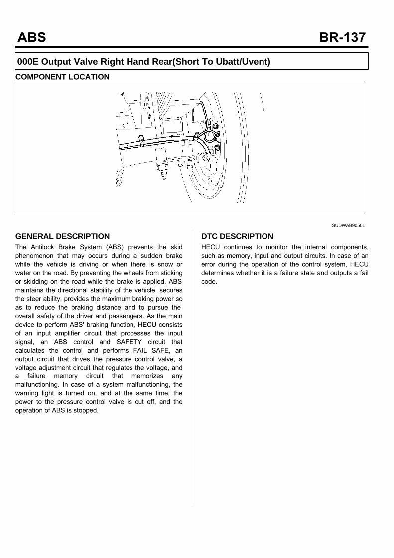
000E Output Valve Right Hand Rear(Short To Ubatt/Uvent)COMPONENT LOCATION
SUDWAB9050L
GENERAL DESCRIPTIONThe Antilock Brake System (ABS) prevents the skidphenomenon that may occurs during a sudden brakewhile the vehicle is driving or when there is snow orwater on the road. By preventing the wheels from stickingor skidding on the road while the brake is applied, ABSmaintains the directional stability of the vehicle, securesthe steer ability, provides the maximum braking power soas to reduce the braking distance and to pursue theoverall safety of the driver and passengers. As the maindevice to perform ABS' braking function, HECU consistsof an input amplifier circuit that processes the inputsignal, an ABS control and SAFETY circuit thatcalculates the control and performs FAIL SAFE, anoutput circuit that drives the pressure control valve, avoltage adjustment circuit that regulates the voltage, anda failure memory circuit that memorizes anymalfunctioning. In case of a system malfunctioning, thewarning light is turned on, and at the same time, thepower to the pressure control valve is cut off, and theoperation of ABS is stopped.
DTC DESCRIPTIONHECU continues to monitor the internal components,such as memory, input and output circuits. In case of anerror during the operation of the control system, HECUdetermines whether it is a failure state and outputs a failcode.

DTC DETECTING CONDITIONItem Detecting Condition Possible Cause
DTC Strategy Signal monitoring • Replace ECU.
Enable Conditions Ignition ON
Threshold Value When the HECU detects malfunction in the control system
Diagnosis Time Below 1,000 ms
Fail Safe Fuel Cut No • ABS disabled
Fuel Limit Yes
MIL Yes
MONITOR SCAN TOOL DATA1. Connect the scan tool to the self-diagnosisconnector.
2. Turn the ignition ON.3. Select the data "Actuation test"
4. Check the right hand rear outlet valve for operationwhen activating the actuator. Specification: Normal if the activating sound isheard.
SUDWAB9014L
Fig1) Right hand rear outlet valve Actuation test at IGON
5. Does the valve activate normally?
There may be a transient trouble due to defectivevalve or a past trouble which did not erase thememory of HECU after having repair.And go to "Verification of Vehicle Repair” procedure.
Go to "Component Inspection" procedure.
TERMINAL & CONNECTOR INSPECTION1. Many malfunctions in the electrical system arecaused by poor harness, and terminals.Faults can also be caused by interference from otherelectrical systems, and mechanical or chemicaldamage.
2. Thoroughly check connectors for looseness, poorconnection, bent, corrosion, contamination,deterioration, or damage.
3. Has a problem been found?
Repair as necessary and then go to “Verification ofVehicle Repair” procedure.

Go to “Signal Circuit Inspection” procedure.
COMPONENT INSPECTION1. Start the engine.2. Drive the vehicle with approx. 15km/h or higher.3. Turn the ignition ON. Leave the engine OFF.4. Connect the scan tool and check the diagnostictrouble codes by using self-diagnosis.
5. Using the scan tool erase the diagnostic troublecodes stored in the HECU.
6. Check that there are any diagnostic trouble codes byusing self-diagnosis with the scan tool.
7. Are any diagnostic trouble codes (DTCs) detected?
Check that the DTCs have disappeared afterreplacing with a known-good HECU. If the problemhas solved, we may guess the HECU is problem.Replace the HECU and go to “Verification of VehicleRepair” procedure.
There may be a defective valve component or atransient trouble due to a past trouble which did noterase the memory of HECU after having repair. Andgo to "Verification of Vehicle Repair” procedure.
VERIFICATION OF VEHICLE REPAIRAfter a repair, it is essential to verify that the fault hasbeen corrected.1. Connect the scan tool and perform the self diagnosis.Check diagnostic trouble codes.
2. Clear the diagnostic trouble codes (DTCs) stored inthe ECM by using the scan tool.
3. Drive the vehicle under conditions noted in failurerecords.
4. Check that there are any DTCs by performing selfdiagnosis with the scan tool.
5. Did the DTC return?
Go to the applicable DTC procedure.
System OK

000F Input Valve Left Hand Rear(Short To Ubatt/Uvent)COMPONENT LOCATION
SUDWAB9048L
GENERAL DESCRIPTIONThe Antilock Brake System (ABS) prevents the skidphenomenon that may occurs during a sudden brakewhile the vehicle is driving or when there is snow orwater on the road. By preventing the wheels from stickingor skidding on the road while the brake is applied, ABSmaintains the directional stability of the vehicle, securesthe steer ability, provides the maximum braking power soas to reduce the braking distance and to pursue theoverall safety of the driver and passengers. As the maindevice to perform ABS' braking function, HECU consistsof an input amplifier circuit that processes the inputsignal, an ABS control and SAFETY circuit thatcalculates the control and performs FAIL SAFE, anoutput circuit that drives the pressure control valve, avoltage adjustment circuit that regulates the voltage, anda failure memory circuit that memorizes anymalfunctioning. In case of a system malfunctioning, thewarning light is turned on, and at the same time, thepower to the pressure control valve is cut off, and theoperation of ABS is stopped.
DTC DESCRIPTIONHECU continues to monitor the internal components,such as memory, input and output circuits. In case of anerror during the operation of the control system, HECUdetermines whether it is a failure state and outputs a failcode.
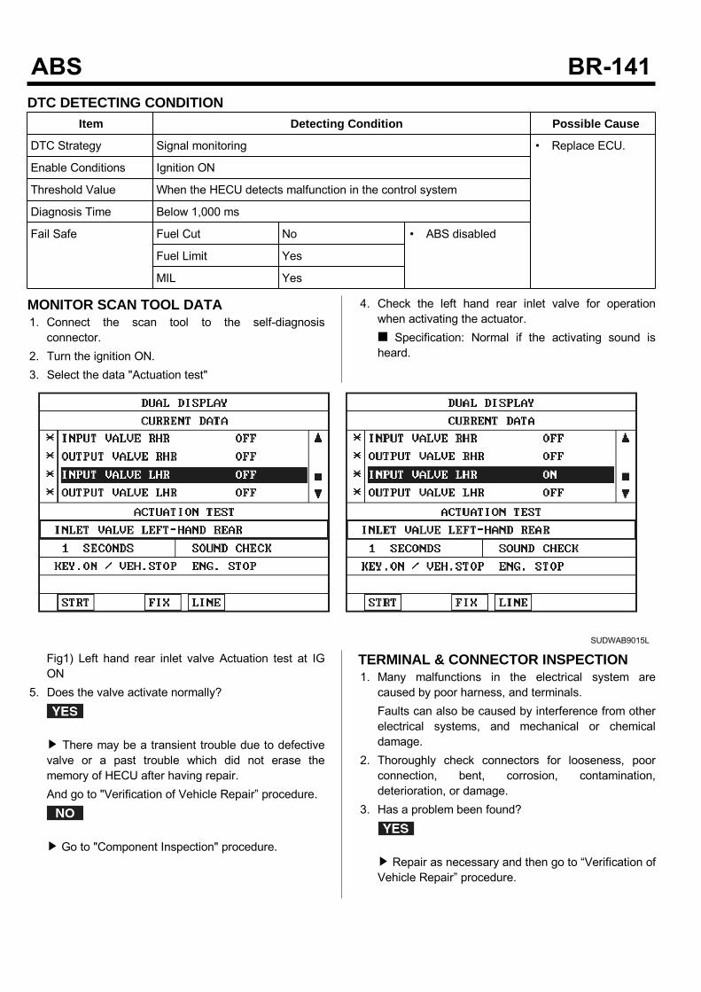
DTC DETECTING CONDITIONItem Detecting Condition Possible Cause
DTC Strategy Signal monitoring • Replace ECU.
Enable Conditions Ignition ON
Threshold Value When the HECU detects malfunction in the control system
Diagnosis Time Below 1,000 ms
Fail Safe Fuel Cut No • ABS disabled
Fuel Limit Yes
MIL Yes
MONITOR SCAN TOOL DATA1. Connect the scan tool to the self-diagnosisconnector.
2. Turn the ignition ON.3. Select the data "Actuation test"
4. Check the left hand rear inlet valve for operationwhen activating the actuator. Specification: Normal if the activating sound isheard.
SUDWAB9015L
Fig1) Left hand rear inlet valve Actuation test at IGON
5. Does the valve activate normally?
There may be a transient trouble due to defectivevalve or a past trouble which did not erase thememory of HECU after having repair.And go to "Verification of Vehicle Repair” procedure.
Go to "Component Inspection" procedure.
TERMINAL & CONNECTOR INSPECTION1. Many malfunctions in the electrical system arecaused by poor harness, and terminals.Faults can also be caused by interference from otherelectrical systems, and mechanical or chemicaldamage.
2. Thoroughly check connectors for looseness, poorconnection, bent, corrosion, contamination,deterioration, or damage.
3. Has a problem been found?
Repair as necessary and then go to “Verification ofVehicle Repair” procedure.

Go to “Signal Circuit Inspection” procedure.
COMPONENT INSPECTION1. Start the engine.2. Drive the vehicle with approx. 15km/h or higher.3. Turn the ignition ON. Leave the engine OFF.4. Connect the scan tool and check the diagnostictrouble codes by using self-diagnosis.
5. Using the scan tool erase the diagnostic troublecodes stored in the HECU.
6. Check that there are any diagnostic trouble codes byusing self-diagnosis with the scan tool.
7. Are any diagnostic trouble codes (DTCs) detected?
Check that the DTCs have disappeared afterreplacing with a known-good HECU. If the problemhas solved, we may guess the HECU is problem.Replace the HECU and go to “Verification of VehicleRepair” procedure.
There may be a defective valve component or atransient trouble due to a past trouble which did noterase the memory of HECU after having repair. Andgo to "Verification of Vehicle Repair” procedure.
VERIFICATION OF VEHICLE REPAIRAfter a repair, it is essential to verify that the fault hasbeen corrected.1. Connect the scan tool and perform the self diagnosis.Check diagnostic trouble codes.
2. Clear the diagnostic trouble codes (DTCs) stored inthe ECM by using the scan tool.
3. Drive the vehicle under conditions noted in failurerecords.
4. Check that there are any DTCs by performing selfdiagnosis with the scan tool.
5. Did the DTC return?
Go to the applicable DTC procedure.
System OK

0010 Output Valve Left Hand Rear(Short To Ubatt/Uvent)COMPONENT LOCATION
SUDWAB9048L
GENERAL DESCRIPTIONThe Antilock Brake System (ABS) prevents the skidphenomenon that may occurs during a sudden brakewhile the vehicle is driving or when there is snow orwater on the road. By preventing the wheels from stickingor skidding on the road while the brake is applied, ABSmaintains the directional stability of the vehicle, securesthe steer ability, provides the maximum braking power soas to reduce the braking distance and to pursue theoverall safety of the driver and passengers. As the maindevice to perform ABS' braking function, HECU consistsof an input amplifier circuit that processes the inputsignal, an ABS control and SAFETY circuit thatcalculates the control and performs FAIL SAFE, anoutput circuit that drives the pressure control valve, avoltage adjustment circuit that regulates the voltage, anda failure memory circuit that memorizes anymalfunctioning. In case of a system malfunctioning, thewarning light is turned on, and at the same time, thepower to the pressure control valve is cut off, and theoperation of ABS is stopped.
DTC DESCRIPTIONHECU continues to monitor the internal components,such as memory, input and output circuits. In case of anerror during the operation of the control system, HECUdetermines whether it is a failure state and outputs a failcode.

DTC DETECTING CONDITIONItem Detecting Condition Possible Cause
DTC Strategy Signal monitoring • Replace ECU.
Enable Conditions Ignition ON
Threshold Value When the HECU detects malfunction in the control system
Diagnosis Time Below 1,000 ms
Fail Safe Fuel Cut No • ABS disabled
Fuel Limit Yes
MIL Yes
MONITOR SCAN TOOL DATA1. Connect the scan tool to the self-diagnosisconnector.
2. Turn the ignition ON.3. Select the data "Actuation test".
4. Check the left hand rear outlet valve for operationwhen activating the actuator. Specification: Normal if the activating sound isheard.
SUDWAB9016L
Fig1) Left hand rear outlet valve Actuation test at IGON
5. Does the valve activate normally?
There may be a transient trouble due to defectivevalve or a past trouble which did not erase thememory of HECU after having repair.And go to "Verification of Vehicle Repair” procedure.
Go to "Component Inspection" procedure.
TERMINAL & CONNECTOR INSPECTION1. Many malfunctions in the electrical system arecaused by poor harness, and terminals.Faults can also be caused by interference from otherelectrical systems, and mechanical or chemicaldamage.
2. Thoroughly check connectors for looseness, poorconnection, bent, corrosion, contamination,deterioration, or damage.
3. Has a problem been found?
Repair as necessary and then go to “Verification ofVehicle Repair” procedure.

Go to “Signal Circuit Inspection” procedure.
COMPONENT INSPECTION1. Start the engine.2. Drive the vehicle with approx. 15km/h or higher.3. Turn the ignition ON. Leave the engine OFF.4. Connect the scan tool and check the diagnostictrouble codes by using self-diagnosis.
5. Using the scan tool erase the diagnostic troublecodes stored in the HECU.
6. Check that there are any diagnostic trouble codes byusing self-diagnosis with the scan tool.
7. Are any diagnostic trouble codes (DTCs) detected?
Check that the DTCs have disappeared afterreplacing with a known-good HECU. If the problemhas solved, we may guess the HECU is problem.Replace the HECU and go to “Verification of VehicleRepair” procedure.
There may be a defective valve component or atransient trouble due to a past trouble which did noterase the memory of HECU after having repair. Andgo to "Verification of Vehicle Repair” procedure.
VERIFICATION OF VEHICLE REPAIRAfter a repair, it is essential to verify that the fault hasbeen corrected.1. Connect the scan tool and perform the self diagnosis.Check diagnostic trouble codes.
2. Clear the diagnostic trouble codes (DTCs) stored inthe ECM by using the scan tool.
3. Drive the vehicle under conditions noted in failurerecords.
4. Check that there are any DTCs by performing selfdiagnosis with the scan tool.
5. Did the DTC return?
Go to the applicable DTC procedure.
System OK
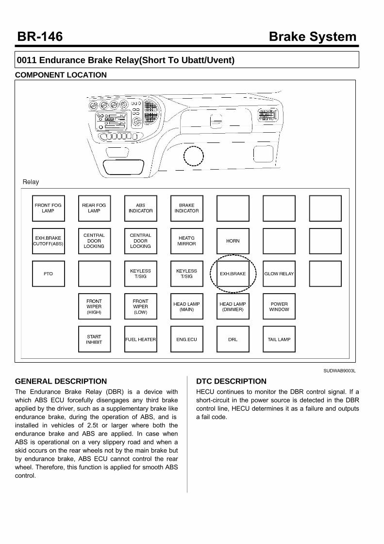
0011 Endurance Brake Relay(Short To Ubatt/Uvent)COMPONENT LOCATION
SUDWAB9003L
GENERAL DESCRIPTIONThe Endurance Brake Relay (DBR) is a device withwhich ABS ECU forcefully disengages any third brakeapplied by the driver, such as a supplementary brake likeendurance brake, during the operation of ABS, and isinstalled in vehicles of 2.5t or larger where both theendurance brake and ABS are applied. In case whenABS is operational on a very slippery road and when askid occurs on the rear wheels not by the main brake butby endurance brake, ABS ECU cannot control the rearwheel. Therefore, this function is applied for smooth ABScontrol.
DTC DESCRIPTIONHECU continues to monitor the DBR control signal. If ashort-circuit in the power source is detected in the DBRcontrol line, HECU determines it as a failure and outputsa fail code.
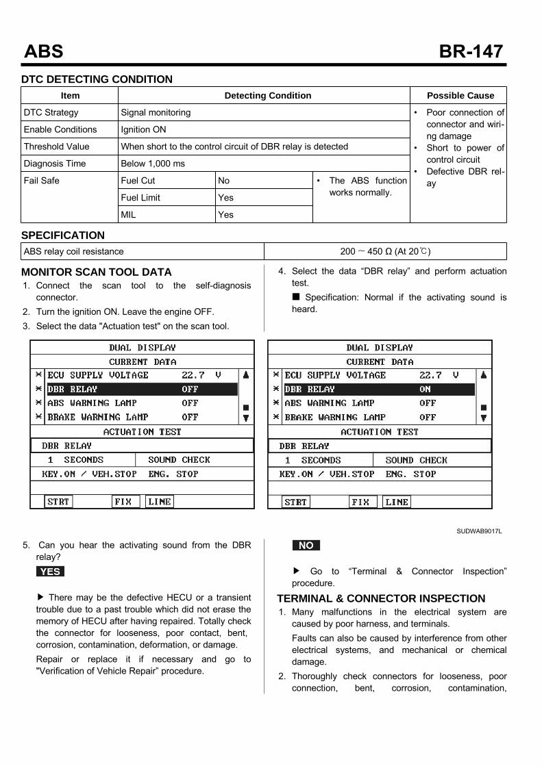
DTC DETECTING CONDITIONItem Detecting Condition Possible Cause
DTC Strategy Signal monitoring • Poor connection ofconnector and wiri-ng damage
• Short to power ofcontrol circuit
• Defective DBR rel-ay
Enable Conditions Ignition ON
Threshold Value When short to the control circuit of DBR relay is detected
Diagnosis Time Below 1,000 ms
Fail Safe Fuel Cut No • The ABS functionworks normally.Fuel Limit Yes
MIL Yes
SPECIFICATIONABS relay coil resistance 200 ~ 450 Ω (At 20)
MONITOR SCAN TOOL DATA1. Connect the scan tool to the self-diagnosisconnector.
2. Turn the ignition ON. Leave the engine OFF.3. Select the data "Actuation test" on the scan tool.
4. Select the data “DBR relay” and perform actuationtest. Specification: Normal if the activating sound isheard.
SUDWAB9017L
5. Can you hear the activating sound from the DBRrelay?
There may be the defective HECU or a transienttrouble due to a past trouble which did not erase thememory of HECU after having repaired. Totally checkthe connector for looseness, poor contact, bent,corrosion, contamination, deformation, or damage.Repair or replace it if necessary and go to"Verification of Vehicle Repair” procedure.
Go to “Terminal & Connector Inspection”procedure.
TERMINAL & CONNECTOR INSPECTION1. Many malfunctions in the electrical system arecaused by poor harness, and terminals.Faults can also be caused by interference from otherelectrical systems, and mechanical or chemicaldamage.
2. Thoroughly check connectors for looseness, poorconnection, bent, corrosion, contamination,
deterioration, or damage.3. Has a problem been found?
Repair as necessary and then go to “Verification ofVehicle Repair” procedure.
Go to “Signal Circuit Inspection” procedure.
CONTROL CIRCUIT INSPECTION1. Turn the ignition OFF.2. Disconnect the DBR relay connector (M15) andHECU connector (C60).
3. Measure the voltage between the terminal 3 of DBRrelay (M15) and chassis ground. Specification: Below 0~0.1 V
4. Is the voltage measured within specification?
Go to “Component Inspection” procedure.
Repair short to power between terminal of HECUand terminal of DBR relay control and go to“Verification of Vehicle Repair” procedure.
COMPONENT INSPECTION1. Turn the ignition OFF.2. Disconnect the DBR relay connector (M15).3. Measure the resistance between terminals 3 and 5 ofDBR relay component. Specification: DBR relay coil resistance: 200 ~450 Ω (At 20)
4. Measure the resistance between terminals 1 and 4 ofDBR relay while applying and cutting off B+ powerto terminals 3 and 5 of DBR relay. SpecificationContinuity (When applying power)Infinite (When cutting off power)
5. Is the resistance measured within specification?
Go to "Verification of Vehicle Repair” procedure.
Replace the relay and go to "Verification ofVehicle Repair” procedure.
Repeat "Component Inspection" procedure severaltimes.
VERIFICATION OF VEHICLE REPAIRAfter a repair, it is essential to verify that the fault hasbeen corrected.1. Connect the scan tool and perform the self diagnosis.Check diagnostic trouble codes.
2. Clear the diagnostic trouble codes (DTCs) stored inthe ECM by using the scan tool.
3. Drive the vehicle under conditions noted in failurerecords.
4. Check that there are any DTCs by performing selfdiagnosis with the scan tool.
5. Did the DTC return?
Go to the applicable DTC procedure.
System OK
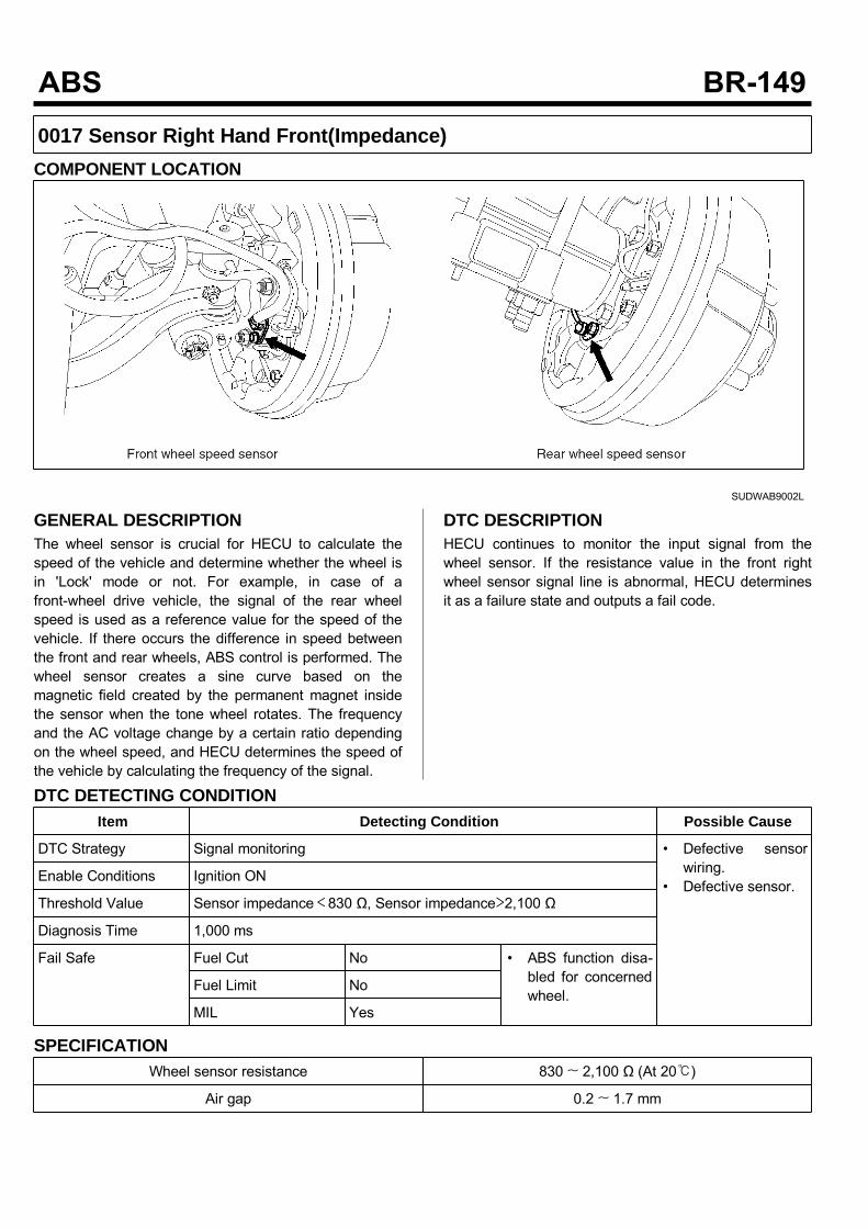
0017 Sensor Right Hand Front(Impedance)COMPONENT LOCATION
SUDWAB9002L
GENERAL DESCRIPTIONThe wheel sensor is crucial for HECU to calculate thespeed of the vehicle and determine whether the wheel isin 'Lock' mode or not. For example, in case of afront-wheel drive vehicle, the signal of the rear wheelspeed is used as a reference value for the speed of thevehicle. If there occurs the difference in speed betweenthe front and rear wheels, ABS control is performed. Thewheel sensor creates a sine curve based on themagnetic field created by the permanent magnet insidethe sensor when the tone wheel rotates. The frequencyand the AC voltage change by a certain ratio dependingon the wheel speed, and HECU determines the speed ofthe vehicle by calculating the frequency of the signal.
DTC DESCRIPTIONHECU continues to monitor the input signal from thewheel sensor. If the resistance value in the front rightwheel sensor signal line is abnormal, HECU determinesit as a failure state and outputs a fail code.
DTC DETECTING CONDITIONItem Detecting Condition Possible Cause
DTC Strategy Signal monitoring • Defective sensorwiring.
• Defective sensor.Enable Conditions Ignition ON
Threshold Value Sensor impedance<830 Ω, Sensor impedance>2,100 Ω
Diagnosis Time 1,000 ms
Fail Safe Fuel Cut No • ABS function disa-bled for concernedwheel.
Fuel Limit No
MIL Yes
SPECIFICATIONWheel sensor resistance 830 ~ 2,100 Ω (At 20)
Air gap 0.2 ~ 1.7 mm

MONITOR SCAN TOOL DATA1. Start the engine.2. Connect the scan tool to the self-diagnosisconnector. Select the service data.
3. Drive the vehicle straight at a constant speed in thenormal road surface.
4. Monitor the data "Wheel speed RHF" parameter onthe scan tool. Specification: Normal if its speed is nearly inaccordance with the speed in the gauge.
SUDWAB9008L
5. Is the data measured within specification?
There may be the poor contact of wheel sensorcircuit or a past trouble which did not erase thememory of HECU after having repaired. Totally checkthe connector for looseness, poor contact, bent,corrosion, contamination, deformation, or damage.Repair or replace it if necessary and go to"Verification of Vehicle Repair” procedure.
Go to “Terminal & Connector Inspection”procedure.
TERMINAL & CONNECTOR INSPECTION1. Many malfunctions in the electrical system arecaused by poor harness, and terminals.Faults can also be caused by interference from otherelectrical systems, and mechanical or chemicaldamage.
2. Thoroughly check connectors for looseness, poorconnection, bent, corrosion, contamination,deterioration, or damage.
3. Has a problem been found?
Repair as necessary and then go to “Verification ofVehicle Repair” procedure.
Go to “Signal Circuit Inspection” procedure.
SIGNAL CIRCUIT INSPECTIONSignal (+) Open Inspection1. Disconnect the HECU connector and the wheelspeed sensor connector.
2. Turn the ignition ON. Leave the engine OFF.3. Measure the resistance between the terminal 25 ofHECU harness connector (C60) and the terminal 1 ofwheel speed sensor harness connector (C30). Specification: Continuity
4. Is the resistance measured within specification?
Go to next procedure.
Repair open circuit and go to "Verification ofVehicle Repair" procedure.
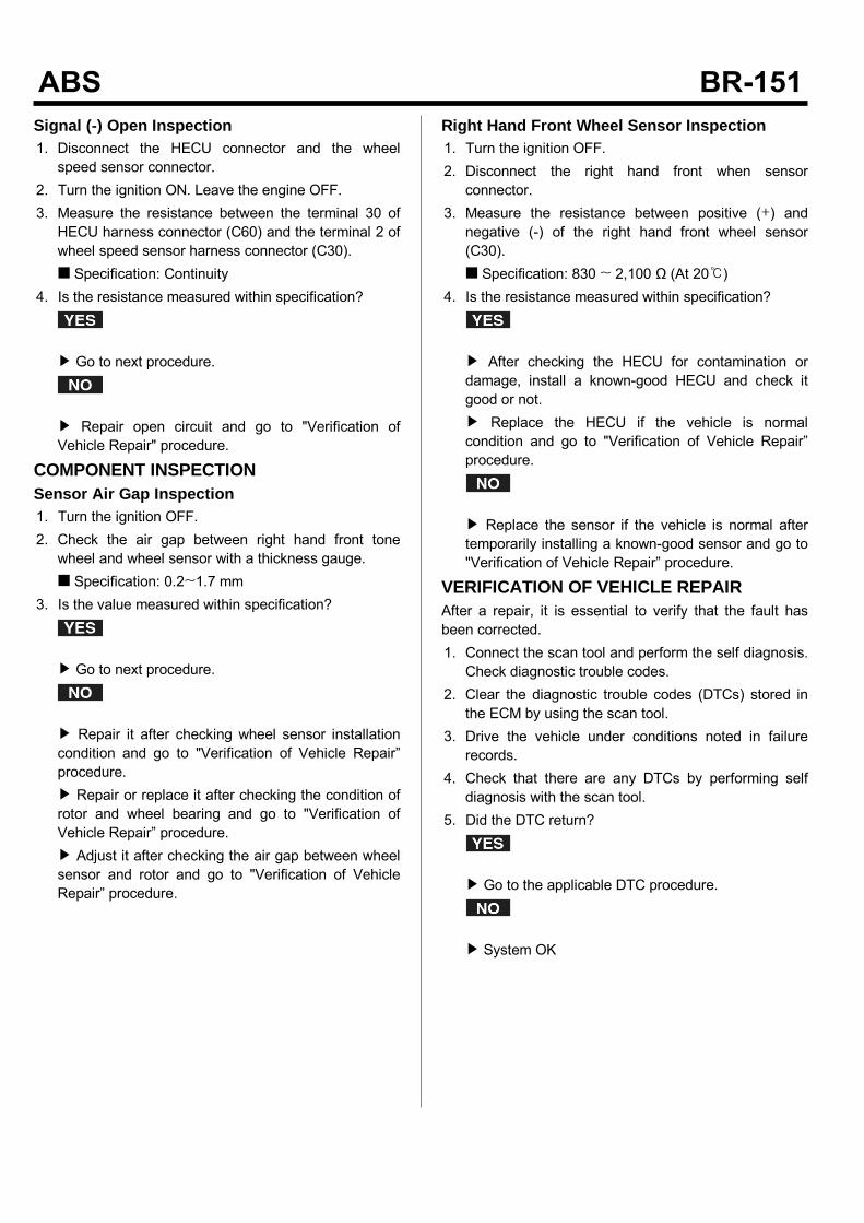
Signal (-) Open Inspection1. Disconnect the HECU connector and the wheelspeed sensor connector.
2. Turn the ignition ON. Leave the engine OFF.3. Measure the resistance between the terminal 30 ofHECU harness connector (C60) and the terminal 2 ofwheel speed sensor harness connector (C30). Specification: Continuity
4. Is the resistance measured within specification?
Go to next procedure.
Repair open circuit and go to "Verification ofVehicle Repair" procedure.
COMPONENT INSPECTIONSensor Air Gap Inspection1. Turn the ignition OFF.2. Check the air gap between right hand front tonewheel and wheel sensor with a thickness gauge. Specification: 0.2~1.7 mm
3. Is the value measured within specification?
Go to next procedure.
Repair it after checking wheel sensor installationcondition and go to "Verification of Vehicle Repair”procedure. Repair or replace it after checking the condition ofrotor and wheel bearing and go to "Verification ofVehicle Repair” procedure. Adjust it after checking the air gap between wheelsensor and rotor and go to "Verification of VehicleRepair” procedure.
Right Hand Front Wheel Sensor Inspection1. Turn the ignition OFF.2. Disconnect the right hand front when sensorconnector.
3. Measure the resistance between positive (+) andnegative (-) of the right hand front wheel sensor(C30). Specification: 830 ~ 2,100 Ω (At 20)
4. Is the resistance measured within specification?
After checking the HECU for contamination ordamage, install a known-good HECU and check itgood or not. Replace the HECU if the vehicle is normalcondition and go to "Verification of Vehicle Repair”procedure.
Replace the sensor if the vehicle is normal aftertemporarily installing a known-good sensor and go to"Verification of Vehicle Repair” procedure.
VERIFICATION OF VEHICLE REPAIRAfter a repair, it is essential to verify that the fault hasbeen corrected.1. Connect the scan tool and perform the self diagnosis.Check diagnostic trouble codes.
2. Clear the diagnostic trouble codes (DTCs) stored inthe ECM by using the scan tool.
3. Drive the vehicle under conditions noted in failurerecords.
4. Check that there are any DTCs by performing selfdiagnosis with the scan tool.
5. Did the DTC return?
Go to the applicable DTC procedure.
System OK
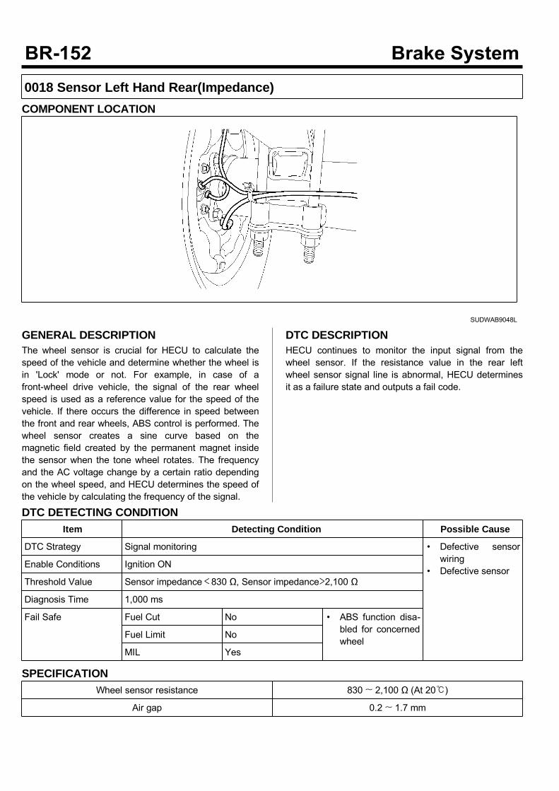
0018 Sensor Left Hand Rear(Impedance)COMPONENT LOCATION
SUDWAB9048L
GENERAL DESCRIPTIONThe wheel sensor is crucial for HECU to calculate thespeed of the vehicle and determine whether the wheel isin 'Lock' mode or not. For example, in case of afront-wheel drive vehicle, the signal of the rear wheelspeed is used as a reference value for the speed of thevehicle. If there occurs the difference in speed betweenthe front and rear wheels, ABS control is performed. Thewheel sensor creates a sine curve based on themagnetic field created by the permanent magnet insidethe sensor when the tone wheel rotates. The frequencyand the AC voltage change by a certain ratio dependingon the wheel speed, and HECU determines the speed ofthe vehicle by calculating the frequency of the signal.
DTC DESCRIPTIONHECU continues to monitor the input signal from thewheel sensor. If the resistance value in the rear leftwheel sensor signal line is abnormal, HECU determinesit as a failure state and outputs a fail code.
DTC DETECTING CONDITIONItem Detecting Condition Possible Cause
DTC Strategy Signal monitoring • Defective sensorwiring
• Defective sensorEnable Conditions Ignition ON
Threshold Value Sensor impedance<830 Ω, Sensor impedance>2,100 Ω
Diagnosis Time 1,000 ms
Fail Safe Fuel Cut No • ABS function disa-bled for concernedwheel
Fuel Limit No
MIL Yes
SPECIFICATIONWheel sensor resistance 830 ~ 2,100 Ω (At 20)
Air gap 0.2 ~ 1.7 mm
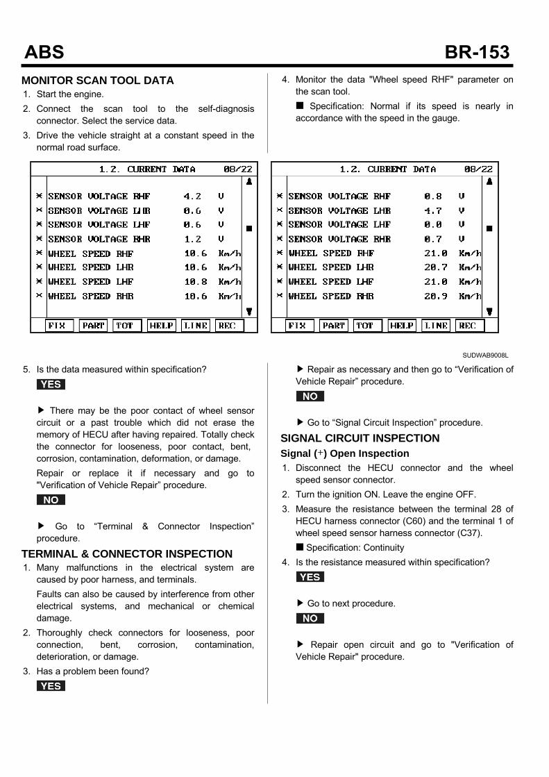
MONITOR SCAN TOOL DATA1. Start the engine.2. Connect the scan tool to the self-diagnosisconnector. Select the service data.
3. Drive the vehicle straight at a constant speed in thenormal road surface.
4. Monitor the data "Wheel speed RHF" parameter onthe scan tool. Specification: Normal if its speed is nearly inaccordance with the speed in the gauge.
SUDWAB9008L
5. Is the data measured within specification?
There may be the poor contact of wheel sensorcircuit or a past trouble which did not erase thememory of HECU after having repaired. Totally checkthe connector for looseness, poor contact, bent,corrosion, contamination, deformation, or damage.Repair or replace it if necessary and go to"Verification of Vehicle Repair” procedure.
Go to “Terminal & Connector Inspection”procedure.
TERMINAL & CONNECTOR INSPECTION1. Many malfunctions in the electrical system arecaused by poor harness, and terminals.Faults can also be caused by interference from otherelectrical systems, and mechanical or chemicaldamage.
2. Thoroughly check connectors for looseness, poorconnection, bent, corrosion, contamination,deterioration, or damage.
3. Has a problem been found?
Repair as necessary and then go to “Verification ofVehicle Repair” procedure.
Go to “Signal Circuit Inspection” procedure.
SIGNAL CIRCUIT INSPECTIONSignal (+) Open Inspection1. Disconnect the HECU connector and the wheelspeed sensor connector.
2. Turn the ignition ON. Leave the engine OFF.3. Measure the resistance between the terminal 28 ofHECU harness connector (C60) and the terminal 1 ofwheel speed sensor harness connector (C37). Specification: Continuity
4. Is the resistance measured within specification?
Go to next procedure.
Repair open circuit and go to "Verification ofVehicle Repair" procedure.
Signal (-) Open Inspection1. Disconnect the HECU connector and the wheelspeed sensor connector.
2. Turn the ignition ON. Leave the engine OFF.3. Measure the resistance between the terminal 23 ofHECU harness connector (C60) and the terminal 2 ofwheel speed sensor harness connector (C37). Specification: Continuity
4. Is the resistance measured within specification?
Go to next procedure.
Repair open circuit and go to "Verification ofVehicle Repair" procedure.
COMPONENT INSPECTIONSensor Air Gap Inspection1. Turn the ignition OFF.2. Check the air gap between left hand rear tone wheeland wheel sensor with a thickness gauge. Specification: 0.2~1.7 mm
3. Is the value measured within specification?
Go to next procedure.
Repair it after checking wheel sensor installationcondition and go to "Verification of Vehicle Repair”procedure. Repair or replace it after checking the condition ofrotor and wheel bearing and go to "Verification ofVehicle Repair” procedure. Adjust it after checking the air gap between wheelsensor and rotor and go to "Verification of VehicleRepair” procedure.
Left Hand Rear Wheel Sensor Inspection1. Turn the ignition OFF.2. Disconnect the left hand rear connector (C37).3. Measure the resistance between terminal positive (+)and terminal negative (-) of the left hand rear wheelsensor (C37). Specification: 830 ~ 2100 Ω (At 20)
4. Is the resistance measured within specification?
After checking the HECU for contamination ordamage, install a known-good HECU and check itgood or not. Replace the HECU if the vehicle is normalcondition and go to "Verification of Vehicle Repair”procedure.
Replace the sensor if the vehicle is normal aftertemporarily installing a known-good sensor and go to"Verification of Vehicle Repair” procedure.
VERIFICATION OF VEHICLE REPAIRAfter a repair, it is essential to verify that the fault hasbeen corrected.1. Connect the scan tool and perform the self diagnosis.Check diagnostic trouble codes.
2. Clear the diagnostic trouble codes (DTCs) stored inthe ECM by using the scan tool.
3. Drive the vehicle under conditions noted in failurerecords.
4. Check that there are any DTCs by performing selfdiagnosis with the scan tool.
5. Did the DTC return?
Go to the applicable DTC procedure.
System OK
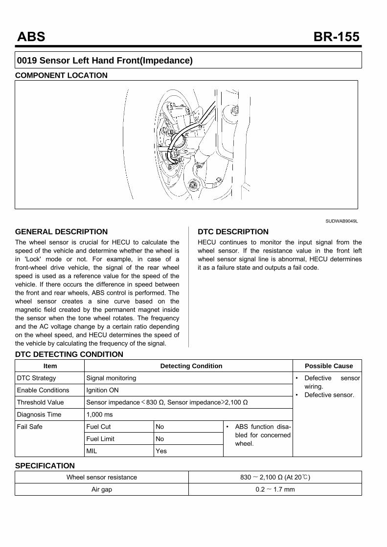
0019 Sensor Left Hand Front(Impedance)COMPONENT LOCATION
SUDWAB9049L
GENERAL DESCRIPTIONThe wheel sensor is crucial for HECU to calculate thespeed of the vehicle and determine whether the wheel isin 'Lock' mode or not. For example, in case of afront-wheel drive vehicle, the signal of the rear wheelspeed is used as a reference value for the speed of thevehicle. If there occurs the difference in speed betweenthe front and rear wheels, ABS control is performed. Thewheel sensor creates a sine curve based on themagnetic field created by the permanent magnet insidethe sensor when the tone wheel rotates. The frequencyand the AC voltage change by a certain ratio dependingon the wheel speed, and HECU determines the speed ofthe vehicle by calculating the frequency of the signal.
DTC DESCRIPTIONHECU continues to monitor the input signal from thewheel sensor. If the resistance value in the front leftwheel sensor signal line is abnormal, HECU determinesit as a failure state and outputs a fail code.
DTC DETECTING CONDITIONItem Detecting Condition Possible Cause
DTC Strategy Signal monitoring • Defective sensorwiring.
• Defective sensor.Enable Conditions Ignition ON
Threshold Value Sensor impedance<830 Ω, Sensor impedance>2,100 Ω
Diagnosis Time 1,000 ms
Fail Safe Fuel Cut No • ABS function disa-bled for concernedwheel.
Fuel Limit No
MIL Yes
SPECIFICATIONWheel sensor resistance 830 ~ 2,100 Ω (At 20)
Air gap 0.2 ~ 1.7 mm
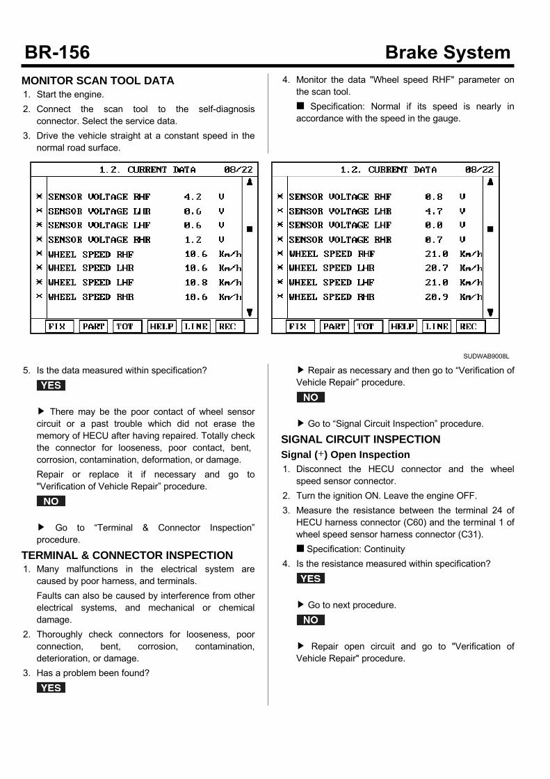
MONITOR SCAN TOOL DATA1. Start the engine.2. Connect the scan tool to the self-diagnosisconnector. Select the service data.
3. Drive the vehicle straight at a constant speed in thenormal road surface.
4. Monitor the data "Wheel speed RHF" parameter onthe scan tool. Specification: Normal if its speed is nearly inaccordance with the speed in the gauge.
SUDWAB9008L
5. Is the data measured within specification?
There may be the poor contact of wheel sensorcircuit or a past trouble which did not erase thememory of HECU after having repaired. Totally checkthe connector for looseness, poor contact, bent,corrosion, contamination, deformation, or damage.Repair or replace it if necessary and go to"Verification of Vehicle Repair” procedure.
Go to “Terminal & Connector Inspection”procedure.
TERMINAL & CONNECTOR INSPECTION1. Many malfunctions in the electrical system arecaused by poor harness, and terminals.Faults can also be caused by interference from otherelectrical systems, and mechanical or chemicaldamage.
2. Thoroughly check connectors for looseness, poorconnection, bent, corrosion, contamination,deterioration, or damage.
3. Has a problem been found?
Repair as necessary and then go to “Verification ofVehicle Repair” procedure.
Go to “Signal Circuit Inspection” procedure.
SIGNAL CIRCUIT INSPECTIONSignal (+) Open Inspection1. Disconnect the HECU connector and the wheelspeed sensor connector.
2. Turn the ignition ON. Leave the engine OFF.3. Measure the resistance between the terminal 24 ofHECU harness connector (C60) and the terminal 1 ofwheel speed sensor harness connector (C31). Specification: Continuity
4. Is the resistance measured within specification?
Go to next procedure.
Repair open circuit and go to "Verification ofVehicle Repair" procedure.
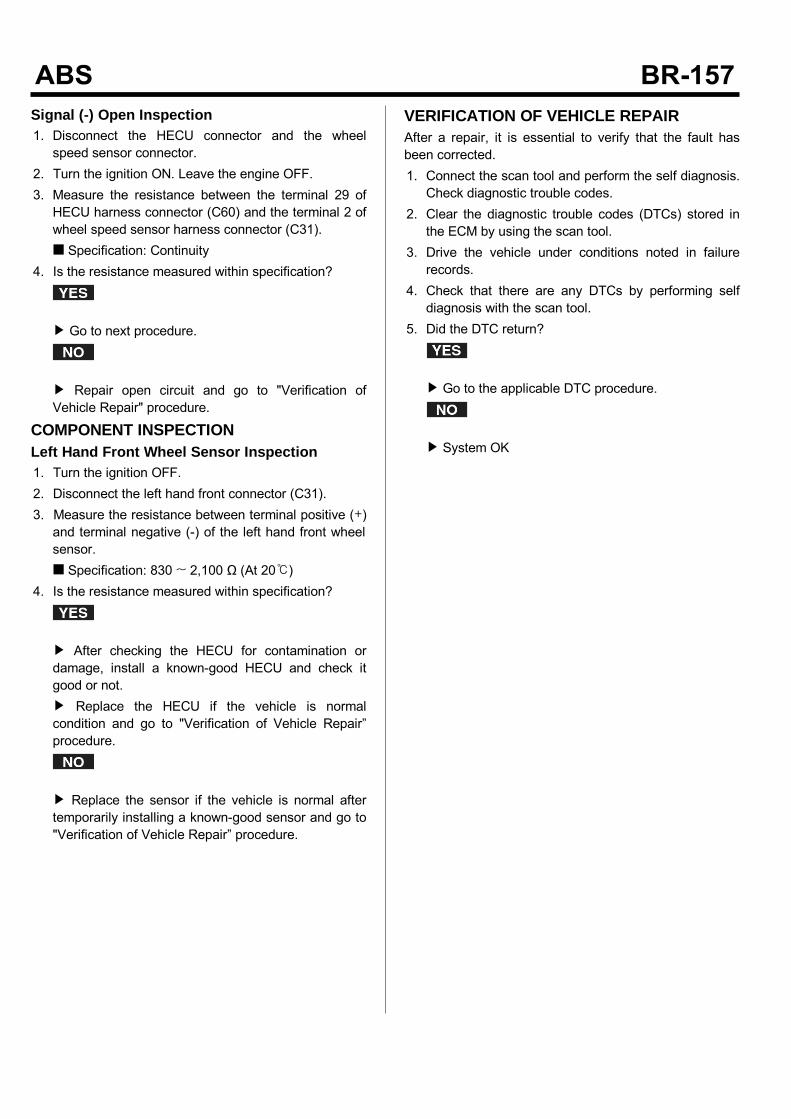
Signal (-) Open Inspection1. Disconnect the HECU connector and the wheelspeed sensor connector.
2. Turn the ignition ON. Leave the engine OFF.3. Measure the resistance between the terminal 29 ofHECU harness connector (C60) and the terminal 2 ofwheel speed sensor harness connector (C31). Specification: Continuity
4. Is the resistance measured within specification?
Go to next procedure.
Repair open circuit and go to "Verification ofVehicle Repair" procedure.
COMPONENT INSPECTIONLeft Hand Front Wheel Sensor Inspection1. Turn the ignition OFF.2. Disconnect the left hand front connector (C31).3. Measure the resistance between terminal positive (+)and terminal negative (-) of the left hand front wheelsensor. Specification: 830 ~ 2,100 Ω (At 20)
4. Is the resistance measured within specification?
After checking the HECU for contamination ordamage, install a known-good HECU and check itgood or not. Replace the HECU if the vehicle is normalcondition and go to "Verification of Vehicle Repair”procedure.
Replace the sensor if the vehicle is normal aftertemporarily installing a known-good sensor and go to"Verification of Vehicle Repair” procedure.
VERIFICATION OF VEHICLE REPAIRAfter a repair, it is essential to verify that the fault hasbeen corrected.1. Connect the scan tool and perform the self diagnosis.Check diagnostic trouble codes.
2. Clear the diagnostic trouble codes (DTCs) stored inthe ECM by using the scan tool.
3. Drive the vehicle under conditions noted in failurerecords.
4. Check that there are any DTCs by performing selfdiagnosis with the scan tool.
5. Did the DTC return?
Go to the applicable DTC procedure.
System OK
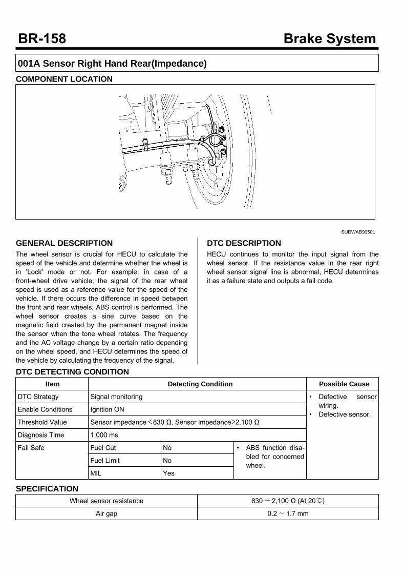
001A Sensor Right Hand Rear(Impedance)COMPONENT LOCATION
SUDWAB9050L
GENERAL DESCRIPTIONThe wheel sensor is crucial for HECU to calculate thespeed of the vehicle and determine whether the wheel isin 'Lock' mode or not. For example, in case of afront-wheel drive vehicle, the signal of the rear wheelspeed is used as a reference value for the speed of thevehicle. If there occurs the difference in speed betweenthe front and rear wheels, ABS control is performed. Thewheel sensor creates a sine curve based on themagnetic field created by the permanent magnet insidethe sensor when the tone wheel rotates. The frequencyand the AC voltage change by a certain ratio dependingon the wheel speed, and HECU determines the speed ofthe vehicle by calculating the frequency of the signal.
DTC DESCRIPTIONHECU continues to monitor the input signal from thewheel sensor. If the resistance value in the rear rightwheel sensor signal line is abnormal, HECU determinesit as a failure state and outputs a fail code.
DTC DETECTING CONDITIONItem Detecting Condition Possible Cause
DTC Strategy Signal monitoring • Defective sensorwiring.
• Defective sensor.Enable Conditions Ignition ON
Threshold Value Sensor impedance<830 Ω, Sensor impedance>2,100 Ω
Diagnosis Time 1,000 ms
Fail Safe Fuel Cut No • ABS function disa-bled for concernedwheel.
Fuel Limit No
MIL Yes
SPECIFICATIONWheel sensor resistance 830 ~ 2,100 Ω (At 20)
Air gap 0.2 ~ 1.7 mm

MONITOR SCAN TOOL DATA1. Start the engine.2. Connect the scan tool to the self-diagnosisconnector. Select the service data.
3. Drive the vehicle straight at a constant speed in thenormal road surface.
4. Monitor the data "Wheel speed RHF" parameter onthe scan tool. Specification: Normal if its speed is nearly inaccordance with the speed in the gauge.
SUDWAB9008L
5. Is the data measured within specification?
There may be the poor contact of wheel sensorcircuit or a past trouble which did not erase thememory of HECU after having repaired. Totally checkthe connector for looseness, poor contact, bent,corrosion, contamination, deformation, or damage.Repair or replace it if necessary and go to"Verification of Vehicle Repair” procedure.
Go to “Terminal & Connector Inspection”procedure.
TERMINAL & CONNECTOR INSPECTION1. Many malfunctions in the electrical system arecaused by poor harness, and terminals.Faults can also be caused by interference from otherelectrical systems, and mechanical or chemicaldamage.
2. Thoroughly check connectors for looseness, poorconnection, bent, corrosion, contamination,deterioration, or damage.
3. Has a problem been found?
Repair as necessary and then go to “Verification ofVehicle Repair” procedure.
Go to “Signal Circuit Inspection” procedure.
SIGNAL CIRCUIT INSPECTIONSignal (+) Open Inspection1. Disconnect the HECU connector and the wheelspeed sensor connector.
2. Turn the ignition ON. Leave the engine OFF.3. Measure the resistance between the terminal 22 ofHECU harness connector (C60) and the terminal 1 ofwheel speed sensor harness connector (C36). Specification: Continuity
4. Is the resistance measured within specification?
Go to next procedure.
Repair open circuit and go to "Verification ofVehicle Repair" procedure.
Signal (-) Open Inspection1. Disconnect the HECU connector and the wheelspeed sensor connector.
2. Turn the ignition ON. Leave the engine OFF.3. Measure the resistance between the terminal 27 ofHECU harness connector (C60) and the terminal 2 ofwheel speed sensor harness connector (C36). Specification: Continuity
4. Is the resistance measured within specification?
Go to next procedure.
Repair open circuit and go to "Verification ofVehicle Repair" procedure.
COMPONENT INSPECTIONRight hand rear Wheel Sensor Inspection1. Turn the ignition OFF.2. Disconnect the right hand rear connector (C36).3. Measure the resistance between terminal positive (+)and terminal negative (-) of the right hand rear wheelsensor (C36). Specification: 830 ~ 2100 Ω (At 20)
4. Is the resistance measured within specification?
After checking the HECU for contamination ordamage, install a known-good HECU and check itgood or not. Replace the HECU if the vehicle is normalcondition and go to "Verification of Vehicle Repair”procedure.
Replace the sensor if the vehicle is normal aftertemporarily installing a known-good sensor and go to"Verification of Vehicle Repair” procedure.
VERIFICATION OF VEHICLE REPAIRAfter a repair, it is essential to verify that the fault hasbeen corrected.1. Connect the scan tool and perform the selfdiagnosis.Check diagnostic trouble codes.
2. Clear the diagnostic trouble codes (DTCs) stored inthe ECM by using the scan tool.
3. Drive the vehicle under conditions noted in failurerecords.
4. Check that there are any DTCs by performing selfdiagnosis with the scan tool.
5. Did the DTC return?
Go to the applicable DTC procedure.
System OK

001B Input Valve Right Hand Front(Open Circuit)COMPONENT LOCATION
SUDWAB9002L
GENERAL DESCRIPTIONThe Antilock Brake System (ABS) prevents the skidphenomenon that may occurs during a sudden brakewhile the vehicle is driving or when there is snow orwater on the road. By preventing the wheels from stickingor skidding on the road while the brake is applied, ABSmaintains the directional stability of the vehicle, securesthe steer ability, provides the maximum braking power soas to reduce the braking distance and to pursue theoverall safety of the driver and passengers. As the maindevice to perform ABS' braking function, HECU consistsof an input amplifier circuit that processes the inputsignal, an ABS control and SAFETY circuit thatcalculates the control and performs FAIL SAFE, anoutput circuit that drives the pressure control valve, avoltage adjustment circuit that regulates the voltage, anda failure memory circuit that memorizes anymalfunctioning. In case of a system malfunctioning, thewarning light is turned on, and at the same time, thepower to the pressure control valve is cut off, and theoperation of ABS is stopped.
DTC DESCRIPTIONHECU continues to monitor the internal components,such as memory, input and output circuits. In case of anerror during the operation of the control system, HECUdetermines whether it is a failure state and outputs a failcode.
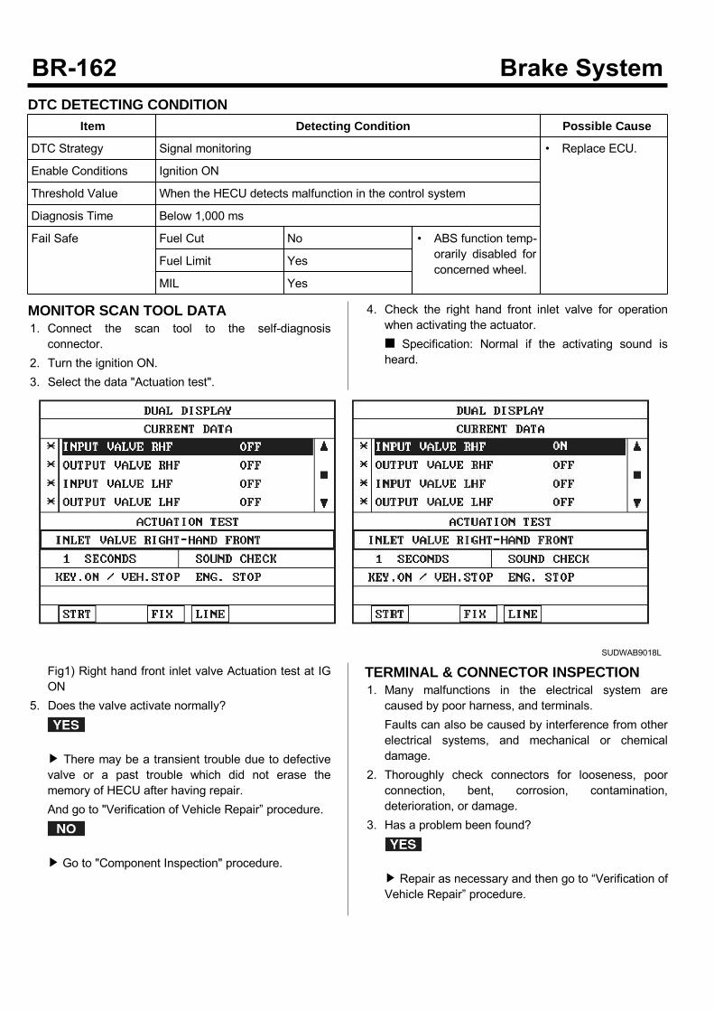
DTC DETECTING CONDITIONItem Detecting Condition Possible Cause
DTC Strategy Signal monitoring • Replace ECU.
Enable Conditions Ignition ON
Threshold Value When the HECU detects malfunction in the control system
Diagnosis Time Below 1,000 ms
Fail Safe Fuel Cut No • ABS function temp-orarily disabled forconcerned wheel.
Fuel Limit Yes
MIL Yes
MONITOR SCAN TOOL DATA1. Connect the scan tool to the self-diagnosisconnector.
2. Turn the ignition ON.3. Select the data "Actuation test".
4. Check the right hand front inlet valve for operationwhen activating the actuator. Specification: Normal if the activating sound isheard.
SUDWAB9018L
Fig1) Right hand front inlet valve Actuation test at IGON
5. Does the valve activate normally?
There may be a transient trouble due to defectivevalve or a past trouble which did not erase thememory of HECU after having repair.And go to "Verification of Vehicle Repair” procedure.
Go to "Component Inspection" procedure.
TERMINAL & CONNECTOR INSPECTION1. Many malfunctions in the electrical system arecaused by poor harness, and terminals.Faults can also be caused by interference from otherelectrical systems, and mechanical or chemicaldamage.
2. Thoroughly check connectors for looseness, poorconnection, bent, corrosion, contamination,deterioration, or damage.
3. Has a problem been found?
Repair as necessary and then go to “Verification ofVehicle Repair” procedure.

Go to “Signal Circuit Inspection” procedure.
COMPONENT INSPECTION1. Start the engine.2. Drive the vehicle with approx. 15km/h or higher.3. Turn the ignition ON. Leave the engine OFF.4. Connect the scan tool and check the diagnostictrouble codes by using self-diagnosis.
5. Using the scan tool erase the diagnostic troublecodes stored in the HECU.
6. Check that there are any diagnostic trouble codes byusing self-diagnosis with the scan tool.
7. Are any diagnostic trouble codes (DTCs) detected?
Check that the DTCs have disappeared afterreplacing with a known-good HECU. If the problemhas solved, we may guess the HECU is problem.Replace the HECU and go to “Verification of VehicleRepair” procedure.
There may be a defective valve component or atransient trouble due to a past trouble which did noterase the memory of HECU after having repair. Andgo to "Verification of Vehicle Repair” procedure.
VERIFICATION OF VEHICLE REPAIRAfter a repair, it is essential to verify that the fault hasbeen corrected.1. Connect the scan tool and perform the self diagnosis.Check diagnostic trouble codes.
2. Clear the diagnostic trouble codes (DTCs) stored inthe ECM by using the scan tool.
3. Drive the vehicle under conditions noted in failurerecords.
4. Check that there are any DTCs by performing selfdiagnosis with the scan tool.
5. Did the DTC return?
Go to the applicable DTC procedure.
System OK

001C Output Valve Right Hand Front(Open Circuit)COMPONENT LOCATION
SUDWAB9002L
GENERAL DESCRIPTIONThe Antilock Brake System (ABS) prevents the skidphenomenon that may occurs during a sudden brakewhile the vehicle is driving or when there is snow orwater on the road. By preventing the wheels from stickingor skidding on the road while the brake is applied, ABSmaintains the directional stability of the vehicle, securesthe steer ability, provides the maximum braking power soas to reduce the braking distance and to pursue theoverall safety of the driver and passengers. As the maindevice to perform ABS' braking function, HECU consistsof an input amplifier circuit that processes the inputsignal, an ABS control and SAFETY circuit thatcalculates the control and performs FAIL SAFE, anoutput circuit that drives the pressure control valve, avoltage adjustment circuit that regulates the voltage, anda failure memory circuit that memorizes anymalfunctioning. In case of a system malfunctioning, thewarning light is turned on, and at the same time, thepower to the pressure control valve is cut off, and theoperation of ABS is stopped.
DTC DESCRIPTIONHECU continues to monitor the internal components,such as memory, input and output circuits. In case of anerror during the operation of the control system, HECUdetermines whether it is a failure state and outputs a failcode.

DTC DETECTING CONDITIONItem Detecting Condition Possible Cause
DTC Strategy Signal monitoring • Replace ECU.
Enable Conditions Ignition ON
Threshold Value When the HECU detects malfunction in the control system
Diagnosis Time Below 1,000 ms
Fail Safe Fuel Cut No • ABS function temp-orarily disabled forconcerned wheel.
Fuel Limit Yes
MIL Yes
MONITOR SCAN TOOL DATA1. Connect the scan tool to the self-diagnosisconnector.
2. Turn the ignition ON.3. Select the data "Actuation test".
4. Check the right hand front outlet valve for operationwhen activating the actuator. Specification: Normal if the activating sound isheard.
SUDWAB9019L
Fig1) Right hand front outlet valve Actuation test atIG ON
5. Does the valve activate normally?
There may be a transient trouble due to defectivevalve or a past trouble which did not erase thememory of HECU after having repair.And go to "Verification of Vehicle Repair” procedure.
Go to "Component Inspection" procedure.
TERMINAL & CONNECTOR INSPECTION1. Many malfunctions in the electrical system arecaused by poor harness, and terminals.Faults can also be caused by interference from otherelectrical systems, and mechanical or chemicaldamage.
2. Thoroughly check connectors for looseness, poorconnection, bent, corrosion, contamination,deterioration, or damage.
3. Has a problem been found?
Repair as necessary and then go to “Verification ofVehicle Repair” procedure.

Go to “Signal Circuit Inspection” procedure.
COMPONENT INSPECTION1. Start the engine.2. Drive the vehicle with approx. 15km/h or higher.3. Turn the ignition ON. Leave the engine OFF.4. Connect the scan tool and check the diagnostictrouble codes by using self-diagnosis.
5. Using the scan tool erase the diagnostic troublecodes stored in the HECU.
6. Check that there are any diagnostic trouble codes byusing self-diagnosis with the scan tool.
7. Are any diagnostic trouble codes (DTCs) detected?
Check that the DTCs have disappeared afterreplacing with a known-good HECU. If the problemhas solved, we may guess the HECU is problem.Replace the HECU and go to “Verification of VehicleRepair” procedure.
There may be a defective valve component or atransient trouble due to a past trouble which did noterase the memory of HECU after having repair. Andgo to "Verification of Vehicle Repair” procedure.
VERIFICATION OF VEHICLE REPAIRAfter a repair, it is essential to verify that the fault hasbeen corrected.1. Connect the scan tool and perform the self diagnosis.Check diagnostic trouble codes.
2. Clear the diagnostic trouble codes (DTCs) stored inthe ECM by using the scan tool.
3. Drive the vehicle under conditions noted in failurerecords.
4. Check that there are any DTCs by performing selfdiagnosis with the scan tool.
5. Did the DTC return?
Go to the applicable DTC procedure.
System OK

001D Input Valve Left Hand Front(Open Circuit)COMPONENT LOCATION
SUDWAB9049L
GENERAL DESCRIPTIONThe Antilock Brake System (ABS) prevents the skidphenomenon that may occurs during a sudden brakewhile the vehicle is driving or when there is snow orwater on the road. By preventing the wheels from stickingor skidding on the road while the brake is applied, ABSmaintains the directional stability of the vehicle, securesthe steer ability, provides the maximum braking power soas to reduce the braking distance and to pursue theoverall safety of the driver and passengers. As the maindevice to perform ABS' braking function, HECU consistsof an input amplifier circuit that processes the inputsignal, an ABS control and SAFETY circuit thatcalculates the control and performs FAIL SAFE, anoutput circuit that drives the pressure control valve, avoltage adjustment circuit that regulates the voltage, anda failure memory circuit that memorizes anymalfunctioning. In case of a system malfunctioning, thewarning light is turned on, and at the same time, thepower to the pressure control valve is cut off, and theoperation of ABS is stopped.
DTC DESCRIPTIONHECU continues to monitor the internal components,such as memory, input and output circuits. In case of anerror during the operation of the control system, HECUdetermines whether it is a failure state and outputs a failcode.
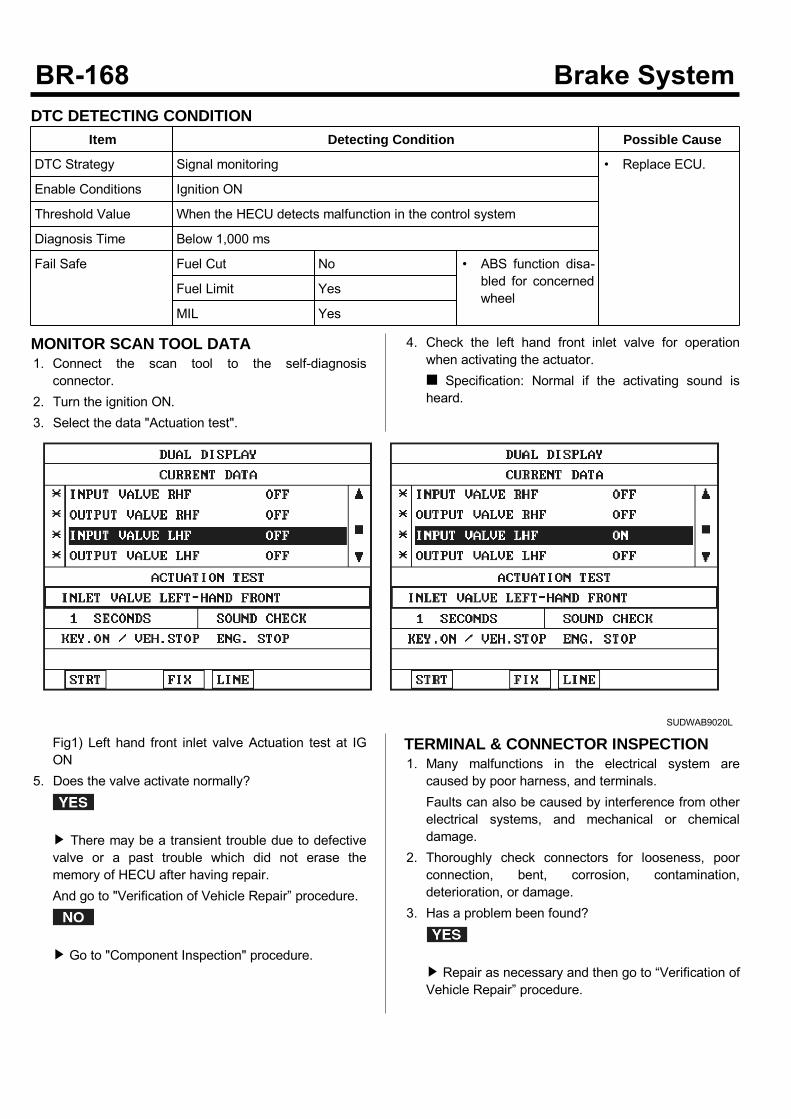
DTC DETECTING CONDITIONItem Detecting Condition Possible Cause
DTC Strategy Signal monitoring • Replace ECU.
Enable Conditions Ignition ON
Threshold Value When the HECU detects malfunction in the control system
Diagnosis Time Below 1,000 ms
Fail Safe Fuel Cut No • ABS function disa-bled for concernedwheel
Fuel Limit Yes
MIL Yes
MONITOR SCAN TOOL DATA1. Connect the scan tool to the self-diagnosisconnector.
2. Turn the ignition ON.3. Select the data "Actuation test".
4. Check the left hand front inlet valve for operationwhen activating the actuator. Specification: Normal if the activating sound isheard.
SUDWAB9020L
Fig1) Left hand front inlet valve Actuation test at IGON
5. Does the valve activate normally?
There may be a transient trouble due to defectivevalve or a past trouble which did not erase thememory of HECU after having repair.And go to "Verification of Vehicle Repair” procedure.
Go to "Component Inspection" procedure.
TERMINAL & CONNECTOR INSPECTION1. Many malfunctions in the electrical system arecaused by poor harness, and terminals.Faults can also be caused by interference from otherelectrical systems, and mechanical or chemicaldamage.
2. Thoroughly check connectors for looseness, poorconnection, bent, corrosion, contamination,deterioration, or damage.
3. Has a problem been found?
Repair as necessary and then go to “Verification ofVehicle Repair” procedure.

Go to “Signal Circuit Inspection” procedure.
COMPONENT INSPECTION1. Start the engine.2. Drive the vehicle with approx. 15km/h or higher.3. Turn the ignition ON. Leave the engine OFF.4. Connect the scan tool and check the diagnostictrouble codes by using self-diagnosis.
5. Using the scan tool erase the diagnostic troublecodes stored in the HECU.
6. Check that there are any diagnostic trouble codes byusing self-diagnosis with the scan tool.
7. Are any diagnostic trouble codes (DTCs) detected?
Check that the DTCs have disappeared afterreplacing with a known-good HECU. If the problemhas solved, we may guess the HECU is problem.Replace the HECU and go to “Verification of VehicleRepair” procedure.
There may be a defective valve component or atransient trouble due to a past trouble which did noterase the memory of HECU after having repair. Andgo to "Verification of Vehicle Repair” procedure.
VERIFICATION OF VEHICLE REPAIRAfter a repair, it is essential to verify that the fault hasbeen corrected.1. Connect the scan tool and perform the self diagnosis.Check diagnostic trouble codes.
2. Clear the diagnostic trouble codes (DTCs) stored inthe ECM by using the scan tool.
3. Drive the vehicle under conditions noted in failurerecords.
4. Check that there are any DTCs by performing selfdiagnosis with the scan tool.
5. Did the DTC return?
Go to the applicable DTC procedure.
System OK

001E Output Valve Left Hand Front(Open Circuit)COMPONENT LOCATION
SUDWAB9049L
GENERAL DESCRIPTIONThe Antilock Brake System (ABS) prevents the skidphenomenon that may occurs during a sudden brakewhile the vehicle is driving or when there is snow orwater on the road. By preventing the wheels from stickingor skidding on the road while the brake is applied, ABSmaintains the directional stability of the vehicle, securesthe steer ability, provides the maximum braking power soas to reduce the braking distance and to pursue theoverall safety of the driver and passengers. As the maindevice to perform ABS' braking function, HECU consistsof an input amplifier circuit that processes the inputsignal, an ABS control and SAFETY circuit thatcalculates the control and performs FAIL SAFE, anoutput circuit that drives the pressure control valve, avoltage adjustment circuit that regulates the voltage, anda failure memory circuit that memorizes anymalfunctioning. In case of a system malfunctioning, thewarning light is turned on, and at the same time, thepower to the pressure control valve is cut off, and theoperation of ABS is stopped.
DTC DESCRIPTIONHECU continues to monitor the internal components,such as memory, input and output circuits. In case of anerror during the operation of the control system, HECUdetermines whether it is a failure state and outputs a failcode.

DTC DETECTING CONDITIONItem Detecting Condition Possible Cause
DTC Strategy Signal monitoring • Replace ECU.
Enable Conditions Ignition ON
Threshold Value When the HECU detects malfunction in the control system
Diagnosis Time Below 1,000 ms
Fail Safe Fuel Cut No • ABS function temp-orarily disabled forconcerned wheel.
Fuel Limit Yes
MIL Yes
MONITOR SCAN TOOL DATA1. Connect the scan tool to the self-diagnosisconnector.
2. Turn the ignition ON.3. Select the data "Actuation test".
4. Check the left hand front outlet valve for operationwhen activating the actuator. Specification: Normal if the activating sound isheard.
SUDWAB9021L
Fig1) Left hand front outlet valve Actuation test at IGON
5. Does the valve activate normally?
There may be a transient trouble due to defectivevalve or a past trouble which did not erase thememory of HECU after having repair.And go to "Verification of Vehicle Repair” procedure.
Go to "Component Inspection" procedure.
TERMINAL & CONNECTOR INSPECTION1. Many malfunctions in the electrical system arecaused by poor harness, and terminals.Faults can also be caused by interference from otherelectrical systems, and mechanical or chemicaldamage.
2. Thoroughly check connectors for looseness, poorconnection, bent, corrosion, contamination,deterioration, or damage.
3. Has a problem been found?
Repair as necessary and then go to “Verification ofVehicle Repair” procedure.
Go to “Signal Circuit Inspection” procedure.
COMPONENT INSPECTION1. Start the engine.2. Drive the vehicle with approx. 15km/h or higher.3. Turn the ignition ON. Leave the engine OFF.4. Connect the scan tool and check the diagnostictrouble codes by using self-diagnosis.
5. Using the scan tool erase the diagnostic troublecodes stored in the HECU.
6. Check that there are any diagnostic trouble codes byusing self-diagnosis with the scan tool.
7. Are any diagnostic trouble codes (DTCs) detected?
Check that the DTCs have disappeared afterreplacing with a known-good HECU. If the problemhas solved, we may guess the HECU is problem.Replace the HECU and go to “Verification of VehicleRepair” procedure.
There may be a defective valve component or atransient trouble due to a past trouble which did noterase the memory of HECU after having repair. Andgo to "Verification of Vehicle Repair” procedure.
VERIFICATION OF VEHICLE REPAIRAfter a repair, it is essential to verify that the fault hasbeen corrected.1. Connect the scan tool and perform the selfdiagnosis.Check diagnostic trouble codes.
2. Clear the diagnostic trouble codes (DTCs) stored inthe ECM by using the scan tool.
3. Drive the vehicle under conditions noted in failurerecords.
4. Check that there are any DTCs by performing selfdiagnosis with the scan tool.
5. Did the DTC return?
Go to the applicable DTC procedure.
System OK

001F Input Valve Right Hand Rear(Open Circuit)COMPONENT LOCATION
SUDWAB9050L
GENERAL DESCRIPTIONThe Antilock Brake System (ABS) prevents the skidphenomenon that may occurs during a sudden brakewhile the vehicle is driving or when there is snow orwater on the road. By preventing the wheels from stickingor skidding on the road while the brake is applied, ABSmaintains the directional stability of the vehicle, securesthe steer ability, provides the maximum braking power soas to reduce the braking distance and to pursue theoverall safety of the driver and passengers. As the maindevice to perform ABS' braking function, HECU consistsof an input amplifier circuit that processes the inputsignal, an ABS control and SAFETY circuit thatcalculates the control and performs FAIL SAFE, anoutput circuit that drives the pressure control valve, avoltage adjustment circuit that regulates the voltage, anda failure memory circuit that memorizes anymalfunctioning. In case of a system malfunctioning, thewarning light is turned on, and at the same time, thepower to the pressure control valve is cut off, and theoperation of ABS is stopped.
DTC DESCRIPTIONHECU continues to monitor the internal components,such as memory, input and output circuits. In case of anerror during the operation of the control system, HECUdetermines whether it is a failure state and outputs a failcode.

DTC DETECTING CONDITIONItem Detecting Condition Possible Cause
DTC Strategy Signal monitoring • Replace ECU.
Enable Conditions Ignition ON
Threshold Value When the HECU detects malfunction in the control system
Diagnosis Time Below 1,000 ms
Fail Safe Fuel Cut No • ABS function temp-orarily disabled forconcerned wheel.
Fuel Limit Yes
MIL Yes
MONITOR SCAN TOOL DATA1. Connect the scan tool to the self-diagnosisconnector.
2. Turn the ignition ON.3. Select the data "Actuation test".
4. Check the right hand rear inlet valve for operationwhen activating the actuator. Specification: Normal if the activating sound isheard.
SUDWAB9022L
Fig1) Right hand rear inlet valve Actuation test at IGON
5. Does the valve activate normally?
There may be a transient trouble due to defectivevalve or a past trouble which did not erase thememory of HECU after having repair.And go to "Verification of Vehicle Repair” procedure.
Go to "Component Inspection" procedure.
TERMINAL & CONNECTOR INSPECTION1. Many malfunctions in the electrical system arecaused by poor harness, and terminals.Faults can also be caused by interference from otherelectrical systems, and mechanical or chemicaldamage.
2. Thoroughly check connectors for looseness, poorconnection, bent, corrosion, contamination,deterioration, or damage.
3. Has a problem been found?
Repair as necessary and then go to “Verification ofVehicle Repair” procedure.

Go to “Signal Circuit Inspection” procedure.
COMPONENT INSPECTION1. Start the engine.2. Drive the vehicle with approx. 15km/h or higher.3. Turn the ignition ON. Leave the engine OFF.4. Connect the scan tool and check the diagnostictrouble codes by using self-diagnosis.
5. Using the scan tool erase the diagnostic troublecodes stored in the HECU.
6. Check that there are any diagnostic trouble codes byusing self-diagnosis with the scan tool.
7. Are any diagnostic trouble codes (DTCs) detected?
Check that the DTCs have disappeared afterreplacing with a known-good HECU. If the problemhas solved, we may guess the HECU is problem.Replace the HECU and go to “Verification of VehicleRepair” procedure.
There may be a defective valve component or atransient trouble due to a past trouble which did noterase the memory of HECU after having repair. Andgo to "Verification of Vehicle Repair” procedure.
VERIFICATION OF VEHICLE REPAIRAfter a repair, it is essential to verify that the fault hasbeen corrected.1. Connect the scan tool and perform the self diagnosis.Check diagnostic trouble codes.
2. Clear the diagnostic trouble codes (DTCs) stored inthe ECM by using the scan tool.
3. Drive the vehicle under conditions noted in failurerecords.
4. Check that there are any DTCs by performing selfdiagnosis with the scan tool.
5. Did the DTC return?
Go to the applicable DTC procedure.
System OK

0020 Output Valve Right Hand Rear(Open Circuit)COMPONENT LOCATION
SUDWAB9050L
GENERAL DESCRIPTIONThe Antilock Brake System (ABS) prevents the skidphenomenon that may occurs during a sudden brakewhile the vehicle is driving or when there is snow orwater on the road. By preventing the wheels from stickingor skidding on the road while the brake is applied, ABSmaintains the directional stability of the vehicle, securesthe steer ability, provides the maximum braking power soas to reduce the braking distance and to pursue theoverall safety of the driver and passengers. As the maindevice to perform ABS' braking function, HECU consistsof an input amplifier circuit that processes the inputsignal, an ABS control and SAFETY circuit thatcalculates the control and performs FAIL SAFE, anoutput circuit that drives the pressure control valve, avoltage adjustment circuit that regulates the voltage, anda failure memory circuit that memorizes anymalfunctioning. In case of a system malfunctioning, thewarning light is turned on, and at the same time, thepower to the pressure control valve is cut off, and theoperation of ABS is stopped.
DTC DESCRIPTIONHECU continues to monitor the internal components,such as memory, input and output circuits. In case of anerror during the operation of the control system, HECUdetermines whether it is a failure state and outputs a failcode.

DTC DETECTING CONDITIONItem Detecting Condition Possible Cause
DTC Strategy Signal monitoring • Replace ECU.
Enable Conditions Ignition ON
Threshold Value When the HECU detects malfunction in the control system
Diagnosis Time Below 1,000 ms
Fail Safe Fuel Cut No • ABS function temp-orarily disabled forconcerned wheel.
Fuel Limit Yes
MIL Yes
MONITOR SCAN TOOL DATA1. Connect the scan tool to the self-diagnosisconnector.
2. Turn the ignition ON.3. Select the data "Actuation test".
4. Check the right hand rear outlet valve for operationwhen activating the actuator. Specification: Normal if the activating sound isheard.
SUDWAB9023L
Fig1) Right hand rear outlet valve Actuation test at IGON
5. Does the valve activate normally?
There may be a transient trouble due to defectivevalve or a past trouble which did not erase thememory of HECU after having repair.And go to "Verification of Vehicle Repair” procedure.
Go to "Component Inspection" procedure.
TERMINAL & CONNECTOR INSPECTION1. Many malfunctions in the electrical system arecaused by poor harness, and terminals.Faults can also be caused by interference from otherelectrical systems, and mechanical or chemicaldamage.
2. Thoroughly check connectors for looseness, poorconnection, bent, corrosion, contamination,deterioration, or damage.
3. Has a problem been found?
Repair as necessary and then go to “Verification ofVehicle Repair” procedure.

Go to “Signal Circuit Inspection” procedure.
COMPONENT INSPECTION1. Start the engine.2. Drive the vehicle with approx. 15km/h or higher.3. Turn the ignition ON. Leave the engine OFF.4. Connect the scan tool and check the diagnostictrouble codes by using self-diagnosis.
5. Using the scan tool erase the diagnostic troublecodes stored in the HECU.
6. Check that there are any diagnostic trouble codes byusing self-diagnosis with the scan tool.
7. Are any diagnostic trouble codes (DTCs) detected?
Check that the DTCs have disappeared afterreplacing with a known-good HECU. If the problemhas solved, we may guess the HECU is problem.Replace the HECU and go to “Verification of VehicleRepair” procedure.
There may be a defective valve component or atransient trouble due to a past trouble which did noterase the memory of HECU after having repair. Andgo to "Verification of Vehicle Repair” procedure.
VERIFICATION OF VEHICLE REPAIRAfter a repair, it is essential to verify that the fault hasbeen corrected.1. Connect the scan tool and perform the self diagnosis.Check diagnostic trouble codes.
2. Clear the diagnostic trouble codes (DTCs) stored inthe ECM by using the scan tool.
3. Drive the vehicle under conditions noted in failurerecords.
4. Check that there are any DTCs by performing selfdiagnosis with the scan tool.
5. Did the DTC return?
Go to the applicable DTC procedure.
System OK

0021 Input Valve Left Hand Rear(Open Circuit)COMPONENT LOCATION
SUDWAB9048L
GENERAL DESCRIPTIONThe Antilock Brake System (ABS) prevents the skidphenomenon that may occurs during a sudden brakewhile the vehicle is driving or when there is snow orwater on the road. By preventing the wheels from stickingor skidding on the road while the brake is applied, ABSmaintains the directional stability of the vehicle, securesthe steer ability, provides the maximum braking power soas to reduce the braking distance and to pursue theoverall safety of the driver and passengers. As the maindevice to perform ABS' braking function, HECU consistsof an input amplifier circuit that processes the inputsignal, an ABS control and SAFETY circuit thatcalculates the control and performs FAIL SAFE, anoutput circuit that drives the pressure control valve, avoltage adjustment circuit that regulates the voltage, anda failure memory circuit that memorizes anymalfunctioning. In case of a system malfunctioning, thewarning light is turned on, and at the same time, thepower to the pressure control valve is cut off, and theoperation of ABS is stopped.
DTC DESCRIPTIONHECU continues to monitor the internal components,such as memory, input and output circuits. In case of anerror during the operation of the control system, HECUdetermines whether it is a failure state and outputs a failcode.

DTC DETECTING CONDITIONItem Detecting Condition Possible Cause
DTC Strategy Signal monitoring • Replace ECU.
Enable Conditions Ignition ON
Threshold Value When the HECU detects malfunction in the control system
Diagnosis Time Below 1,000 ms
Fail Safe Fuel Cut No • ABS function temp-orarily disabled forconcerned wheel.
Fuel Limit Yes
MIL Yes
MONITOR SCAN TOOL DATA1. Connect the scan tool to the self-diagnosisconnector.
2. Turn the ignition ON.3. Select the data "Actuation test".
4. Check the left hand rear inlet valve for operationwhen activating the actuator. Specification: Normal if the activating sound isheard.
SUDWAB9024L
Fig1) Left hand rear inlet valve Actuation test at IGON
5. Does the valve activate normally?
There may be a transient trouble due to defectivevalve or a past trouble which did not erase thememory of HECU after having repair.And go to "Verification of Vehicle Repair” procedure.
Go to "Component Inspection" procedure.
TERMINAL & CONNECTOR INSPECTION1. Many malfunctions in the electrical system arecaused by poor harness, and terminals.Faults can also be caused by interference from otherelectrical systems, and mechanical or chemicaldamage.
2. Thoroughly check connectors for looseness, poorconnection, bent, corrosion, contamination,deterioration, or damage.
3. Has a problem been found?
Repair as necessary and then go to “Verification ofVehicle Repair” procedure.

Go to “Signal Circuit Inspection” procedure.
COMPONENT INSPECTION1. Start the engine.2. Drive the vehicle with approx. 15km/h or higher.3. Turn the ignition ON. Leave the engine OFF.4. Connect the scan tool and check the diagnostictrouble codes by using self-diagnosis.
5. Using the scan tool erase the diagnostic troublecodes stored in the HECU.
6. Check that there are any diagnostic trouble codes byusing self-diagnosis with the scan tool.
7. Are any diagnostic trouble codes (DTCs) detected?
Check that the DTCs have disappeared afterreplacing with a known-good HECU. If the problemhas solved, we may guess the HECU is problem.Replace the HECU and go to “Verification of VehicleRepair” procedure.
There may be a defective valve component or atransient trouble due to a past trouble which did noterase the memory of HECU after having repair. Andgo to "Verification of Vehicle Repair” procedure.
VERIFICATION OF VEHICLE REPAIRAfter a repair, it is essential to verify that the fault hasbeen corrected.1. Connect the scan tool and perform the self diagnosis.Check diagnostic trouble codes.
2. Clear the diagnostic trouble codes (DTCs) stored inthe ECM by using the scan tool.
3. Drive the vehicle under conditions noted in failurerecords.
4. Check that there are any DTCs by performing selfdiagnosis with the scan tool.
5. Did the DTC return?
Go to the applicable DTC procedure.
System OK

0022 Output Valve Left Hand Rear(Open Circuit)COMPONENT LOCATION
SUDWAB9048L
GENERAL DESCRIPTIONThe Antilock Brake System (ABS) prevents the skidphenomenon that may occurs during a sudden brakewhile the vehicle is driving or when there is snow orwater on the road. By preventing the wheels from stickingor skidding on the road while the brake is applied, ABSmaintains the directional stability of the vehicle, securesthe steer ability, provides the maximum braking power soas to reduce the braking distance and to pursue theoverall safety of the driver and passengers. As the maindevice to perform ABS' braking function, HECU consistsof an input amplifier circuit that processes the inputsignal, an ABS control and SAFETY circuit thatcalculates the control and performs FAIL SAFE, anoutput circuit that drives the pressure control valve, avoltage adjustment circuit that regulates the voltage, anda failure memory circuit that memorizes anymalfunctioning. In case of a system malfunctioning, thewarning light is turned on, and at the same time, thepower to the pressure control valve is cut off, and theoperation of ABS is stopped.
DTC DESCRIPTIONHECU continues to monitor the internal components,such as memory, input and output circuits. In case of anerror during the operation of the control system, HECUdetermines whether it is a failure state and outputs a failcode.

DTC DETECTING CONDITIONItem Detecting Condition Possible Cause
DTC Strategy Signal monitoring • Replace ECU.
Enable Conditions Ignition ON
Threshold Value When the HECU detects malfunction in the control system
Diagnosis Time Below 1,000 ms
Fail Safe Fuel Cut No • ABS function temp-orarily disabled forconcerned wheel.
Fuel Limit Yes
MIL Yes
MONITOR SCAN TOOL DATA1. Connect the scan tool to the self-diagnosisconnector.
2. Turn the ignition ON.3. Select the data "Actuation test".
4. Check the left hand rear outlet valve for operationwhen activating the actuator. Specification: Normal if the activating sound isheard.
SUDWAB9025L
Fig1) Left hand rear outlet valve Actuation test at IGON
5. Does the valve activate normally?
There may be a transient trouble due to defectivevalve or a past trouble which did not erase thememory of HECU after having repair.And go to "Verification of Vehicle Repair” procedure.
Go to "Component Inspection" procedure.
TERMINAL & CONNECTOR INSPECTION1. Many malfunctions in the electrical system arecaused by poor harness, and terminals.Faults can also be caused by interference from otherelectrical systems, and mechanical or chemicaldamage.
2. Thoroughly check connectors for looseness, poorconnection, bent, corrosion, contamination,deterioration, or damage.
3. Has a problem been found?
Repair as necessary and then go to “Verification ofVehicle Repair” procedure.

Go to “Signal Circuit Inspection” procedure.
COMPONENT INSPECTION1. Start the engine.2. Drive the vehicle with approx. 15km/h or higher.3. Turn the ignition ON. Leave the engine OFF.4. Connect the scan tool and check the diagnostictrouble codes by using self-diagnosis.
5. Using the scan tool erase the diagnostic troublecodes stored in the HECU.
6. Check that there are any diagnostic trouble codes byusing self-diagnosis with the scan tool.
7. Are any diagnostic trouble codes (DTCs) detected?
Check that the DTCs have disappeared afterreplacing with a known-good HECU. If the problemhas solved, we may guess the HECU is problem.Replace the HECU and go to “Verification of VehicleRepair” procedure.
There may be a defective valve component or atransient trouble due to a past trouble which did noterase the memory of HECU after having repair. Andgo to "Verification of Vehicle Repair” procedure.
VERIFICATION OF VEHICLE REPAIRAfter a repair, it is essential to verify that the fault hasbeen corrected.1. Connect the scan tool and perform the self diagnosis.Check diagnostic trouble codes.
2. Clear the diagnostic trouble codes (DTCs) stored inthe ECM by using the scan tool.
3. Drive the vehicle under conditions noted in failurerecords.
4. Check that there are any DTCs by performing selfdiagnosis with the scan tool.
5. Did the DTC return?
Go to the applicable DTC procedure.
System OK
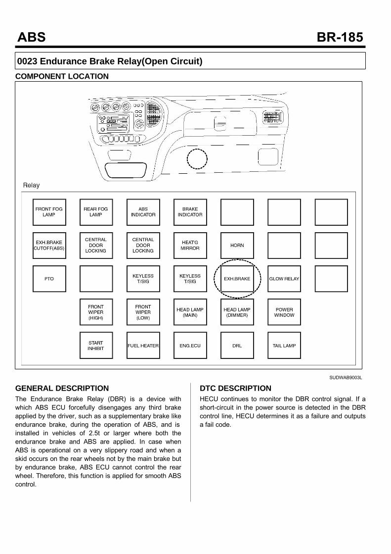
0023 Endurance Brake Relay(Open Circuit)COMPONENT LOCATION
SUDWAB9003L
GENERAL DESCRIPTIONThe Endurance Brake Relay (DBR) is a device withwhich ABS ECU forcefully disengages any third brakeapplied by the driver, such as a supplementary brake likeendurance brake, during the operation of ABS, and isinstalled in vehicles of 2.5t or larger where both theendurance brake and ABS are applied. In case whenABS is operational on a very slippery road and when askid occurs on the rear wheels not by the main brake butby endurance brake, ABS ECU cannot control the rearwheel. Therefore, this function is applied for smooth ABScontrol.
DTC DESCRIPTIONHECU continues to monitor the DBR control signal. If ashort-circuit in the power source is detected in the DBRcontrol line, HECU determines it as a failure and outputsa fail code.
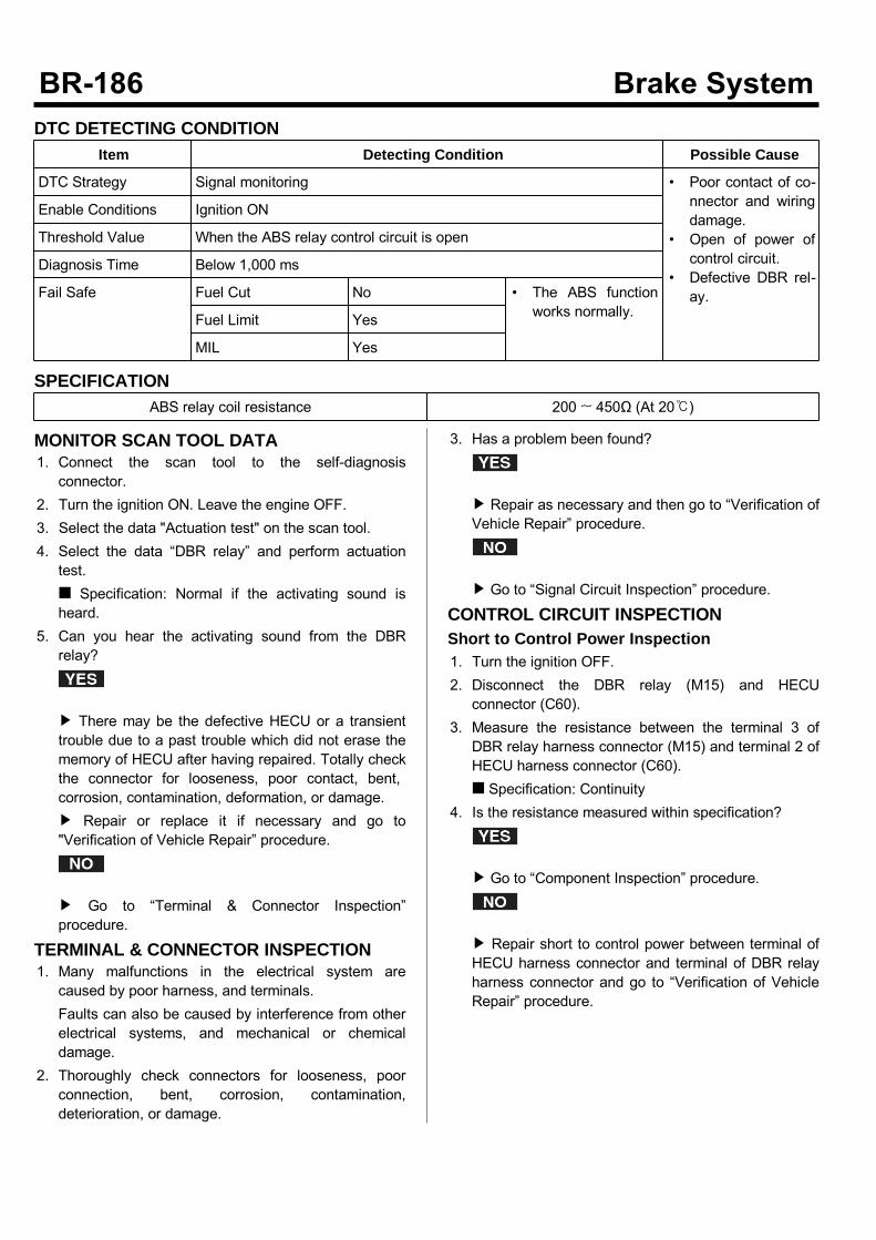
DTC DETECTING CONDITIONItem Detecting Condition Possible Cause
DTC Strategy Signal monitoring • Poor contact of co-nnector and wiringdamage.
• Open of power ofcontrol circuit.
• Defective DBR rel-ay.
Enable Conditions Ignition ON
Threshold Value When the ABS relay control circuit is open
Diagnosis Time Below 1,000 ms
Fail Safe Fuel Cut No • The ABS functionworks normally.Fuel Limit Yes
MIL Yes
SPECIFICATIONABS relay coil resistance 200 ~ 450Ω (At 20)
MONITOR SCAN TOOL DATA1. Connect the scan tool to the self-diagnosisconnector.
2. Turn the ignition ON. Leave the engine OFF.3. Select the data "Actuation test" on the scan tool.4. Select the data “DBR relay” and perform actuationtest. Specification: Normal if the activating sound isheard.
5. Can you hear the activating sound from the DBRrelay?
There may be the defective HECU or a transienttrouble due to a past trouble which did not erase thememory of HECU after having repaired. Totally checkthe connector for looseness, poor contact, bent,corrosion, contamination, deformation, or damage. Repair or replace it if necessary and go to"Verification of Vehicle Repair” procedure.
Go to “Terminal & Connector Inspection”procedure.
TERMINAL & CONNECTOR INSPECTION1. Many malfunctions in the electrical system arecaused by poor harness, and terminals.Faults can also be caused by interference from otherelectrical systems, and mechanical or chemicaldamage.
2. Thoroughly check connectors for looseness, poorconnection, bent, corrosion, contamination,deterioration, or damage.
3. Has a problem been found?
Repair as necessary and then go to “Verification ofVehicle Repair” procedure.
Go to “Signal Circuit Inspection” procedure.
CONTROL CIRCUIT INSPECTIONShort to Control Power Inspection1. Turn the ignition OFF.2. Disconnect the DBR relay (M15) and HECUconnector (C60).
3. Measure the resistance between the terminal 3 ofDBR relay harness connector (M15) and terminal 2 ofHECU harness connector (C60). Specification: Continuity
4. Is the resistance measured within specification?
Go to “Component Inspection” procedure.
Repair short to control power between terminal ofHECU harness connector and terminal of DBR relayharness connector and go to “Verification of VehicleRepair” procedure.
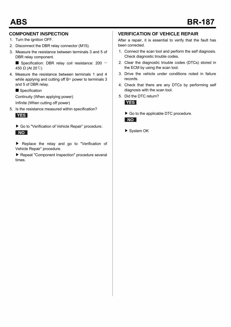
COMPONENT INSPECTION1. Turn the ignition OFF.2. Disconnect the DBR relay connector (M15).3. Measure the resistance between terminals 3 and 5 ofDBR relay component. Specification: DBR relay coil resistance: 200 ~450 Ω (At 20)
4. Measure the resistance between terminals 1 and 4while applying and cutting off B+ power to terminals 3and 5 of DBR relay. SpecificationContinuity (When applying power)Infinite (When cutting off power)
5. Is the resistance measured within specification?
Go to "Verification of Vehicle Repair” procedure.
Replace the relay and go to "Verification ofVehicle Repair” procedure. Repeat "Component Inspection" procedure severaltimes.
VERIFICATION OF VEHICLE REPAIRAfter a repair, it is essential to verify that the fault hasbeen corrected.1. Connect the scan tool and perform the self diagnosis.Check diagnostic trouble codes.
2. Clear the diagnostic trouble codes (DTCs) stored inthe ECM by using the scan tool.
3. Drive the vehicle under conditions noted in failurerecords.
4. Check that there are any DTCs by performing selfdiagnosis with the scan tool.
5. Did the DTC return?
Go to the applicable DTC procedure.
System OK
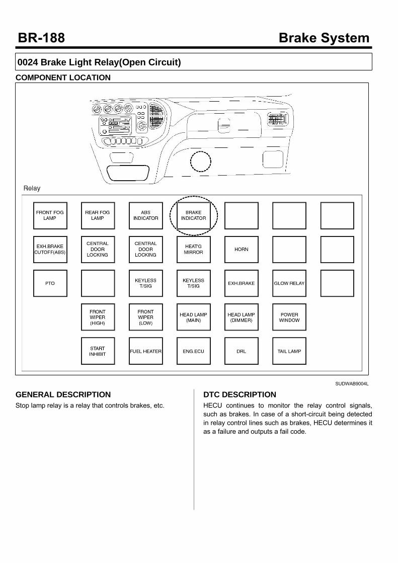
0024 Brake Light Relay(Open Circuit)COMPONENT LOCATION
SUDWAB9004L
GENERAL DESCRIPTIONStop lamp relay is a relay that controls brakes, etc.
DTC DESCRIPTIONHECU continues to monitor the relay control signals,such as brakes. In case of a short-circuit being detectedin relay control lines such as brakes, HECU determines itas a failure and outputs a fail code.
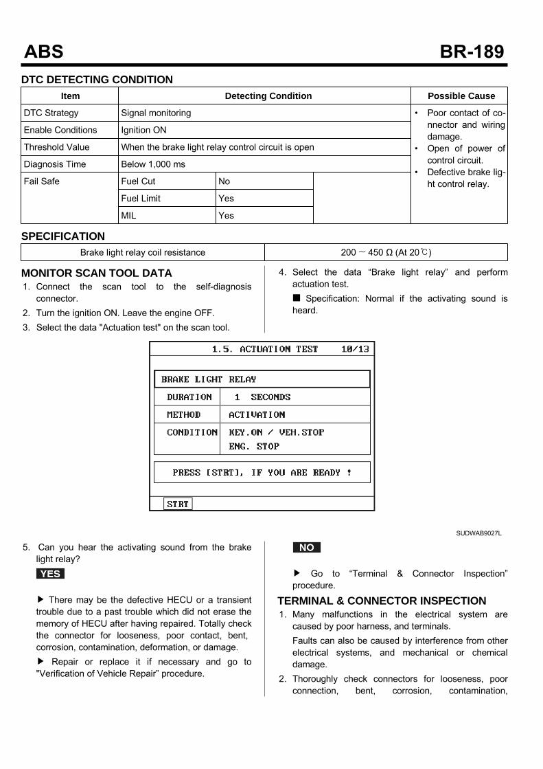
DTC DETECTING CONDITIONItem Detecting Condition Possible Cause
DTC Strategy Signal monitoring • Poor contact of co-nnector and wiringdamage.
• Open of power ofcontrol circuit.
• Defective brake lig-ht control relay.
Enable Conditions Ignition ON
Threshold Value When the brake light relay control circuit is open
Diagnosis Time Below 1,000 ms
Fail Safe Fuel Cut No
Fuel Limit Yes
MIL Yes
SPECIFICATIONBrake light relay coil resistance 200 ~ 450 Ω (At 20)
MONITOR SCAN TOOL DATA1. Connect the scan tool to the self-diagnosisconnector.
2. Turn the ignition ON. Leave the engine OFF.3. Select the data "Actuation test" on the scan tool.
4. Select the data “Brake light relay” and performactuation test. Specification: Normal if the activating sound isheard.
SUDWAB9027L
5. Can you hear the activating sound from the brakelight relay?
There may be the defective HECU or a transienttrouble due to a past trouble which did not erase thememory of HECU after having repaired. Totally checkthe connector for looseness, poor contact, bent,corrosion, contamination, deformation, or damage. Repair or replace it if necessary and go to"Verification of Vehicle Repair” procedure.
Go to “Terminal & Connector Inspection”procedure.
TERMINAL & CONNECTOR INSPECTION1. Many malfunctions in the electrical system arecaused by poor harness, and terminals.Faults can also be caused by interference from otherelectrical systems, and mechanical or chemicaldamage.
2. Thoroughly check connectors for looseness, poorconnection, bent, corrosion, contamination,
deterioration, or damage.3. Has a problem been found?
Repair as necessary and then go to “Verification ofVehicle Repair” procedure.
Go to “Signal Circuit Inspection” procedure.
CONTROL CIRCUIT INSPECTIONShort to Control Power Inspection1. Turn the ignition OFF.2. Disconnect the brake light relay (M102) and HECUconnector (C60).
3. Measure the resistance between the terminal 3 ofbrake light relay harness connector (M102) andterminal 20 of HECU harness connector (C60). Specification: Continuity
4. Is the resistance measured within specification?
Go to “Component Inspection” procedure.
Repair short to control power between terminal ofHECU harness connector and terminal of brake lightrelay control harness connector and go to“Verification of Vehicle Repair” procedure.
COMPONENT INSPECTION1. Turn the ignition OFF.2. Disconnect the brake light relay connector (M102).3. Measure the resistance between terminals 3 and 5 ofABS relay component. Specification: Brake light relay coil resistance: 200~ 450 Ω (At 20)
4. Measure the resistance between terminals 1 and 4 ofbrake light relay while applying and cutting off B+power to terminals 3 and 5 of ABS light relay. Specification:Continuity (When applying power)Infinite (When cutting off power)
5. Is the resistance measured within specification?
Go to "Verification of Vehicle Repair” procedure.
Replace the relay and go to "Verification ofVehicle Repair” procedure. Repeat "Component Inspection" procedure severaltimes.
VERIFICATION OF VEHICLE REPAIRAfter a repair, it is essential to verify that the fault hasbeen corrected.1. Connect the scan tool and perform the self diagnosis.Check diagnostic trouble codes.
2. Clear the diagnostic trouble codes (DTCs) stored inthe ECM by using the scan tool.
3. Drive the vehicle under conditions noted in failurerecords.
4. Check that there are any DTCs by performing selfdiagnosis with the scan tool.
5. Did the DTC return?
Go to the applicable DTC procedure.
System OK
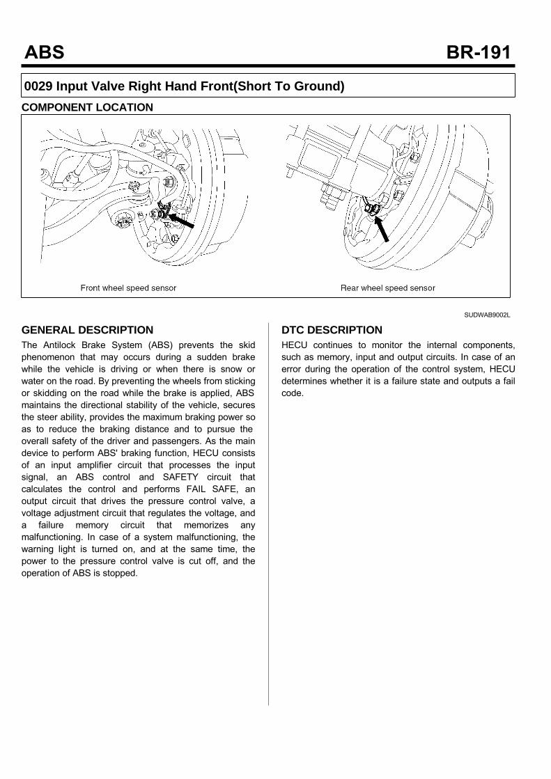
0029 Input Valve Right Hand Front(Short To Ground)COMPONENT LOCATION
SUDWAB9002L
GENERAL DESCRIPTIONThe Antilock Brake System (ABS) prevents the skidphenomenon that may occurs during a sudden brakewhile the vehicle is driving or when there is snow orwater on the road. By preventing the wheels from stickingor skidding on the road while the brake is applied, ABSmaintains the directional stability of the vehicle, securesthe steer ability, provides the maximum braking power soas to reduce the braking distance and to pursue theoverall safety of the driver and passengers. As the maindevice to perform ABS' braking function, HECU consistsof an input amplifier circuit that processes the inputsignal, an ABS control and SAFETY circuit thatcalculates the control and performs FAIL SAFE, anoutput circuit that drives the pressure control valve, avoltage adjustment circuit that regulates the voltage, anda failure memory circuit that memorizes anymalfunctioning. In case of a system malfunctioning, thewarning light is turned on, and at the same time, thepower to the pressure control valve is cut off, and theoperation of ABS is stopped.
DTC DESCRIPTIONHECU continues to monitor the internal components,such as memory, input and output circuits. In case of anerror during the operation of the control system, HECUdetermines whether it is a failure state and outputs a failcode.

DTC DETECTING CONDITIONItem Detecting Condition Possible Cause
DTC Strategy Signal monitoring • Replace ECU.
Enable Conditions Ignition ON
Threshold Value When the HECU detects malfunction in the control system
Diagnosis Time Below 1,000 ms
Fail Safe Fuel Cut No • ABS function temp-orarily disabled forconcerned wheel.
Fuel Limit Yes
MIL Yes
MONITOR SCAN TOOL DATA1. Connect the scan tool to the self-diagnosisconnector.
2. Turn the ignition ON.3. Select the data "Actuation test"
4. Check the right hand front inlet valve for operationwhen activating the actuator. Specification: Normal if the activating sound isheard.
SUDWAB9028L
Fig1) Right hand front inlet valve Actuation test at IGON
5. Does the valve activate normally?
There may be a transient trouble due to defectivevalve or a past trouble which did not erase thememory of HECU after having repair. And go to "Verification of Vehicle Repair”procedure.
Go to "Component Inspection" procedure.
TERMINAL & CONNECTOR INSPECTION1. Many malfunctions in the electrical system arecaused by poor harness, and terminals.Faults can also be caused by interference from otherelectrical systems, and mechanical or chemicaldamage.
2. Thoroughly check connectors for looseness, poorconnection, bent, corrosion, contamination,deterioration, or damage.
3. Has a problem been found?
Repair as necessary and then go to “Verification ofVehicle Repair” procedure.

Go to “Signal Circuit Inspection” procedure.
COMPONENT INSPECTION1. Start the engine.2. Drive the vehicle with approx. 15km/h or higher.3. Turn the ignition ON. Leave the engine OFF.4. Connect the scan tool and check the diagnostictrouble codes by using self-diagnosis.
5. Using the scan tool erase the diagnostic troublecodes stored in the HECU.
6. Check that there are any diagnostic trouble codes byusing self-diagnosis with the scan tool.
7. Are any diagnostic trouble codes (DTCs) detected?
Check that the DTCs have disappeared afterreplacing with a known-good HECU. If the problemhas solved, we may guess the HECU is problem.Replace the HECU and go to “Verification of VehicleRepair” procedure.
There may be a defective valve component or atransient trouble due to a past trouble which did noterase the memory of HECU after having repair. Andgo to "Verification of Vehicle Repair” procedure.
VERIFICATION OF VEHICLE REPAIRAfter a repair, it is essential to verify that the fault hasbeen corrected.1. Connect the scan tool and perform the self diagnosis.Check diagnostic trouble codes.
2. Clear the diagnostic trouble codes (DTCs) stored inthe ECM by using the scan tool.
3. Drive the vehicle under conditions noted in failurerecords.
4. Check that there are any DTCs by performing selfdiagnosis with the scan tool.
5. Did the DTC return?
Go to the applicable DTC procedure.
System OK
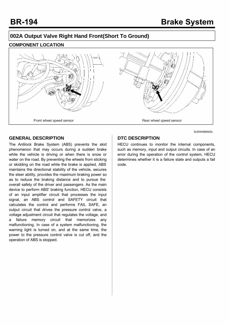
002A Output Valve Right Hand Front(Short To Ground)COMPONENT LOCATION
SUDWAB9002L
GENERAL DESCRIPTIONThe Antilock Brake System (ABS) prevents the skidphenomenon that may occurs during a sudden brakewhile the vehicle is driving or when there is snow orwater on the road. By preventing the wheels from stickingor skidding on the road while the brake is applied, ABSmaintains the directional stability of the vehicle, securesthe steer ability, provides the maximum braking power soas to reduce the braking distance and to pursue theoverall safety of the driver and passengers. As the maindevice to perform ABS' braking function, HECU consistsof an input amplifier circuit that processes the inputsignal, an ABS control and SAFETY circuit thatcalculates the control and performs FAIL SAFE, anoutput circuit that drives the pressure control valve, avoltage adjustment circuit that regulates the voltage, anda failure memory circuit that memorizes anymalfunctioning. In case of a system malfunctioning, thewarning light is turned on, and at the same time, thepower to the pressure control valve is cut off, and theoperation of ABS is stopped.
DTC DESCRIPTIONHECU continues to monitor the internal components,such as memory, input and output circuits. In case of anerror during the operation of the control system, HECUdetermines whether it is a failure state and outputs a failcode.

DTC DETECTING CONDITIONItem Detecting Condition Possible Cause
DTC Strategy Signal monitoring • Replace ECU.
Enable Conditions Ignition ON
Threshold Value When the HECU detects malfunction in the control system
Diagnosis Time Below 1,000 ms
Fail Safe Fuel Cut No • ABS function temp-orarily disabled forconcerned wheel.
Fuel Limit Yes
MIL Yes
MONITOR SCAN TOOL DATA1. Connect the scan tool to the self-diagnosisconnector.
2. Turn the ignition ON.3. Select the data "Actuation test".
4. Check the right hand front outlet valve for operationwhen activating the actuator. Specification: Normal if the activating sound isheard.
SUDWAB9029L
Fig1) Right hand front outlet valve Actuation test atIG ON
5. Does the valve activate normally?
There may be a transient trouble due to defectivevalve or a past trouble which did not erase thememory of HECU after having repair. And go to "Verification of Vehicle Repair”procedure.
Go to "Component Inspection" procedure.
TERMINAL & CONNECTOR INSPECTION1. Many malfunctions in the electrical system arecaused by poor harness, and terminals.Faults can also be caused by interference from otherelectrical systems, and mechanical or chemicaldamage.
2. Thoroughly check connectors for looseness, poorconnection, bent, corrosion, contamination,deterioration, or damage.
3. Has a problem been found?
Repair as necessary and then go to “Verification ofVehicle Repair” procedure.

Go to “Signal Circuit Inspection” procedure.
COMPONENT INSPECTION1. Start the engine.2. Drive the vehicle with approx. 15km/h or higher.3. Turn the ignition ON. Leave the engine OFF.4. Connect the scan tool and check the diagnostictrouble codes by using self-diagnosis.
5. Using the scan tool erase the diagnostic troublecodes stored in the HECU.
6. Check that there are any diagnostic trouble codes byusing self-diagnosis with the scan tool.
7. Are any diagnostic trouble codes (DTCs) detected?
Check that the DTCs have disappeared afterreplacing with a known-good HECU. If the problemhas solved, we may guess the HECU is problem.Replace the HECU and go to “Verification of VehicleRepair” procedure.
There may be a defective valve component or atransient trouble due to a past trouble which did noterase the memory of HECU after having repair. Andgo to "Verification of Vehicle Repair” procedure.
VERIFICATION OF VEHICLE REPAIRAfter a repair, it is essential to verify that the fault hasbeen corrected.1. Connect the scan tool and perform the self diagnosis.Check diagnostic trouble codes.
2. Clear the diagnostic trouble codes (DTCs) stored inthe ECM by using the scan tool.
3. Drive the vehicle under conditions noted in failurerecords.
4. Check that there are any DTCs by performing selfdiagnosis with the scan tool.
5. Did the DTC return?
Go to the applicable DTC procedure.
System OK

002B Input Valve Left Hand Front(Short To Ground)COMPONENT LOCATION
SUDWAB9049L
GENERAL DESCRIPTIONThe Antilock Brake System (ABS) prevents the skidphenomenon that may occurs during a sudden brakewhile the vehicle is driving or when there is snow orwater on the road. By preventing the wheels from stickingor skidding on the road while the brake is applied, ABSmaintains the directional stability of the vehicle, securesthe steer ability, provides the maximum braking power soas to reduce the braking distance and to pursue theoverall safety of the driver and passengers. As the maindevice to perform ABS' braking function, HECU consistsof an input amplifier circuit that processes the inputsignal, an ABS control and SAFETY circuit thatcalculates the control and performs FAIL SAFE, anoutput circuit that drives the pressure control valve, avoltage adjustment circuit that regulates the voltage, anda failure memory circuit that memorizes anymalfunctioning. In case of a system malfunctioning, thewarning light is turned on, and at the same time, thepower to the pressure control valve is cut off, and theoperation of ABS is stopped.
DTC DESCRIPTIONHECU continues to monitor the internal components,such as memory, input and output circuits. In case of anerror during the operation of the control system, HECUdetermines whether it is a failure state and outputs a failcode.
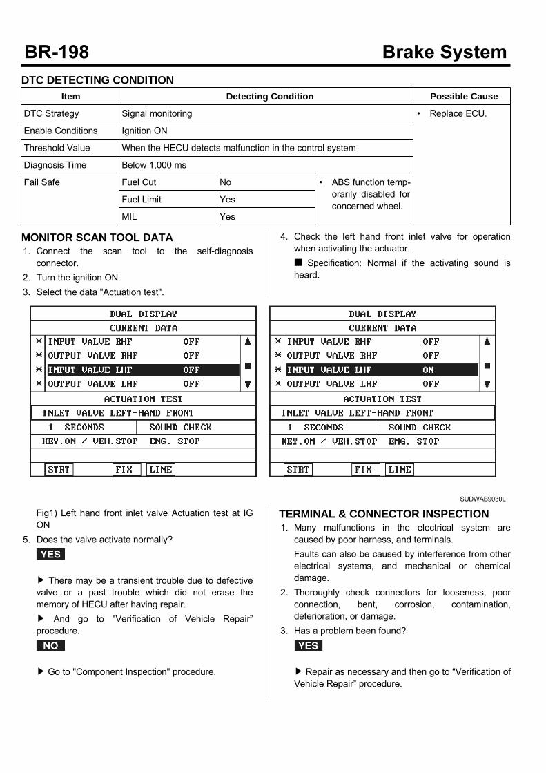
DTC DETECTING CONDITIONItem Detecting Condition Possible Cause
DTC Strategy Signal monitoring • Replace ECU.
Enable Conditions Ignition ON
Threshold Value When the HECU detects malfunction in the control system
Diagnosis Time Below 1,000 ms
Fail Safe Fuel Cut No • ABS function temp-orarily disabled forconcerned wheel.
Fuel Limit Yes
MIL Yes
MONITOR SCAN TOOL DATA1. Connect the scan tool to the self-diagnosisconnector.
2. Turn the ignition ON.3. Select the data "Actuation test".
4. Check the left hand front inlet valve for operationwhen activating the actuator. Specification: Normal if the activating sound isheard.
SUDWAB9030L
Fig1) Left hand front inlet valve Actuation test at IGON
5. Does the valve activate normally?
There may be a transient trouble due to defectivevalve or a past trouble which did not erase thememory of HECU after having repair. And go to "Verification of Vehicle Repair”procedure.
Go to "Component Inspection" procedure.
TERMINAL & CONNECTOR INSPECTION1. Many malfunctions in the electrical system arecaused by poor harness, and terminals.Faults can also be caused by interference from otherelectrical systems, and mechanical or chemicaldamage.
2. Thoroughly check connectors for looseness, poorconnection, bent, corrosion, contamination,deterioration, or damage.
3. Has a problem been found?
Repair as necessary and then go to “Verification ofVehicle Repair” procedure.

Go to “Signal Circuit Inspection” procedure.
COMPONENT INSPECTION1. Start the engine.2. Drive the vehicle with approx. 15km/h or higher.3. Turn the ignition ON. Leave the engine OFF.4. Connect the scan tool and check the diagnostictrouble codes by using self-diagnosis.
5. Using the scan tool erase the diagnostic troublecodes stored in the HECU.
6. Check that there are any diagnostic trouble codes byusing self-diagnosis with the scan tool.
7. Are any diagnostic trouble codes (DTCs) detected?
Check that the DTCs have disappeared afterreplacing with a known-good HECU. If the problemhas solved, we may guess the HECU is problem.Replace the HECU and go to “Verification of VehicleRepair” procedure.
There may be a defective valve component or atransient trouble due to a past trouble which did noterase the memory of HECU after having repair. Andgo to "Verification of Vehicle Repair” procedure.
VERIFICATION OF VEHICLE REPAIRAfter a repair, it is essential to verify that the fault hasbeen corrected.1. Connect the scan tool and perform the self diagnosis.Check diagnostic trouble codes.
2. Clear the diagnostic trouble codes (DTCs) stored inthe ECM by using the scan tool.
3. Drive the vehicle under conditions noted in failurerecords.
4. Check that there are any DTCs by performing selfdiagnosis with the scan tool.
5. Did the DTC return?
Go to the applicable DTC procedure.
System OK

002C Output Valve Left Hand Front(Short To Ground)COMPONENT LOCATION
SUDWAB9049L
GENERAL DESCRIPTIONThe Antilock Brake System (ABS) prevents the skidphenomenon that may occurs during a sudden brakewhile the vehicle is driving or when there is snow orwater on the road. By preventing the wheels from stickingor skidding on the road while the brake is applied, ABSmaintains the directional stability of the vehicle, securesthe steer ability, provides the maximum braking power soas to reduce the braking distance and to pursue theoverall safety of the driver and passengers. As the maindevice to perform ABS' braking function, HECU consistsof an input amplifier circuit that processes the inputsignal, an ABS control and SAFETY circuit thatcalculates the control and performs FAIL SAFE, anoutput circuit that drives the pressure control valve, avoltage adjustment circuit that regulates the voltage, anda failure memory circuit that memorizes anymalfunctioning. In case of a system malfunctioning, thewarning light is turned on, and at the same time, thepower to the pressure control valve is cut off, and theoperation of ABS is stopped.
DTC DESCRIPTIONHECU continues to monitor the internal components,such as memory, input and output circuits. In case of anerror during the operation of the control system, HECUdetermines whether it is a failure state and outputs a failcode.

DTC DETECTING CONDITIONItem Detecting Condition Possible Cause
DTC Strategy Signal monitoring • Replace ECU.
Enable Conditions Ignition ON
Threshold Value When the HECU detects malfunction in the control system
Diagnosis Time Below 1,000 ms
Fail Safe Fuel Cut No • ABS function temp-orarily disabled forconcerned wheel.
Fuel Limit Yes
MIL Yes
MONITOR SCAN TOOL DATA1. Connect the scan tool to the self-diagnosisconnector.
2. Turn the ignition ON.3. Select the data "Actuation test".
4. Check the left hand front outlet valve for operationwhen activating the actuator. Specification: Normal if the activating sound isheard.
SUDWAB9031L
Fig1) Left hand front outlet valve Actuation test at IGON
5. Does the valve activate normally?
There may be a transient trouble due to defectivevalve or a past trouble which did not erase thememory of HECU after having repair. And go to "Verification of Vehicle Repair”procedure.
Go to "Component Inspection" procedure.
TERMINAL & CONNECTOR INSPECTION1. Many malfunctions in the electrical system arecaused by poor harness, and terminals.Faults can also be caused by interference from otherelectrical systems, and mechanical or chemicaldamage.
2. Thoroughly check connectors for looseness, poorconnection, bent, corrosion, contamination,deterioration, or damage.
3. Has a problem been found?
Repair as necessary and then go to “Verification ofVehicle Repair” procedure.
Go to “Signal Circuit Inspection” procedure.
COMPONENT INSPECTION1. Start the engine.2. Drive the vehicle with approx. 15km/h or higher.3. Turn the ignition ON. Leave the engine OFF.4. Connect the scan tool and check the diagnostictrouble codes by using self-diagnosis.
5. Using the scan tool erase the diagnostic troublecodes stored in the HECU.
6. Check that there are any diagnostic trouble codes byusing self-diagnosis with the scan tool.
7. Are any diagnostic trouble codes (DTCs) detected?
Check that the DTCs have disappeared afterreplacing with a known-good HECU. If the problemhas solved, we may guess the HECU is problem.Replace the HECU and go to “Verification of VehicleRepair” procedure.
There may be a defective valve component or atransient trouble due to a past trouble which did noterase the memory of HECU after having repair. Andgo to "Verification of Vehicle Repair” procedure.
VERIFICATION OF VEHICLE REPAIRAfter a repair, it is essential to verify that the fault hasbeen corrected.1. Connect the scan tool and perform the self diagnosis.Check diagnostic trouble codes.
2. Clear the diagnostic trouble codes (DTCs) stored inthe ECM by using the scan tool.
3. Drive the vehicle under conditions noted in failurerecords.
4. Check that there are any DTCs by performing selfdiagnosis with the scan tool.
5. Did the DTC return?
Go to the applicable DTC procedure.
System OK
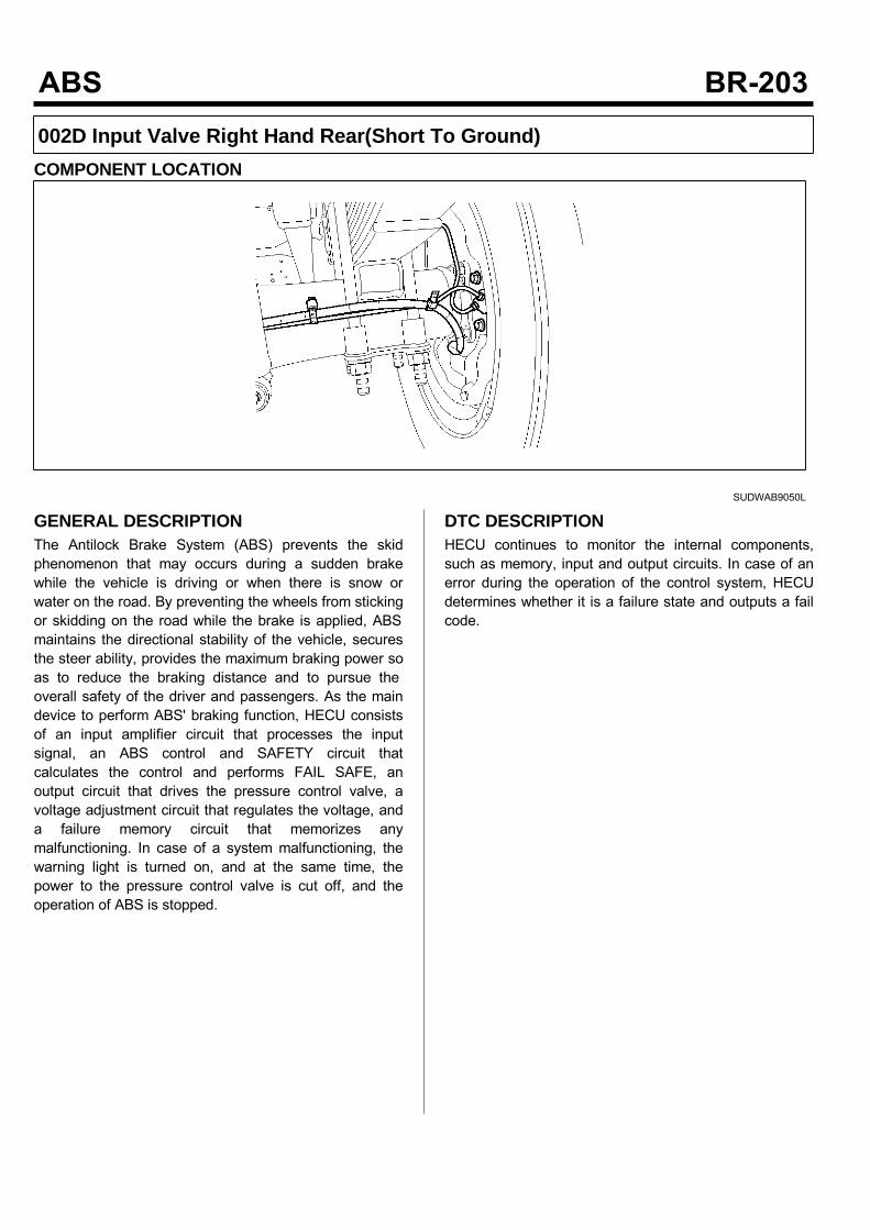
002D Input Valve Right Hand Rear(Short To Ground)COMPONENT LOCATION
SUDWAB9050L
GENERAL DESCRIPTIONThe Antilock Brake System (ABS) prevents the skidphenomenon that may occurs during a sudden brakewhile the vehicle is driving or when there is snow orwater on the road. By preventing the wheels from stickingor skidding on the road while the brake is applied, ABSmaintains the directional stability of the vehicle, securesthe steer ability, provides the maximum braking power soas to reduce the braking distance and to pursue theoverall safety of the driver and passengers. As the maindevice to perform ABS' braking function, HECU consistsof an input amplifier circuit that processes the inputsignal, an ABS control and SAFETY circuit thatcalculates the control and performs FAIL SAFE, anoutput circuit that drives the pressure control valve, avoltage adjustment circuit that regulates the voltage, anda failure memory circuit that memorizes anymalfunctioning. In case of a system malfunctioning, thewarning light is turned on, and at the same time, thepower to the pressure control valve is cut off, and theoperation of ABS is stopped.
DTC DESCRIPTIONHECU continues to monitor the internal components,such as memory, input and output circuits. In case of anerror during the operation of the control system, HECUdetermines whether it is a failure state and outputs a failcode.

DTC DETECTING CONDITIONItem Detecting Condition Possible Cause
DTC Strategy Signal monitoring • Replace ECU.
Enable Conditions Ignition ON
Threshold Value When the HECU detects malfunction in the control system
Diagnosis Time Below 1,000 ms
Fail Safe Fuel Cut No • ABS function temp-orarily disabled forconcerned wheel.
Fuel Limit Yes
MIL Yes
MONITOR SCAN TOOL DATA1. Connect the scan tool to the self-diagnosisconnector.
2. Turn the ignition ON.3. Select the data "Actuation test".
4. Check the right hand rear inlet valve for operationwhen activating the actuator. Specification: Normal if the activating sound isheard.
SUDWAB9032L
Fig1) Right hand rear inlet valve Actuation test at IGON
5. Does the valve activate normally?
There may be a transient trouble due to defectivevalve or a past trouble which did not erase thememory of HECU after having repair. And go to "Verification of Vehicle Repair”procedure.
Go to "Component Inspection" procedure.
TERMINAL & CONNECTOR INSPECTION1. Many malfunctions in the electrical system arecaused by poor harness, and terminals.Faults can also be caused by interference from otherelectrical systems, and mechanical or chemicaldamage.
2. Thoroughly check connectors for looseness, poorconnection, bent, corrosion, contamination,deterioration, or damage.
3. Has a problem been found?
Repair as necessary and then go to “Verification ofVehicle Repair” procedure.

Go to “Signal Circuit Inspection” procedure.
COMPONENT INSPECTION1. Start the engine.2. Drive the vehicle with approx. 15km/h or higher.3. Turn the ignition ON. Leave the engine OFF.4. Connect the scan tool and check the diagnostictrouble codes by using self-diagnosis.
5. Using the scan tool erase the diagnostic troublecodes stored in the HECU.
6. Check that there are any diagnostic trouble codes byusing self-diagnosis with the scan tool.
7. Are any diagnostic trouble codes (DTCs) detected?
Check that the DTCs have disappeared afterreplacing with a known-good HECU. If the problemhas solved, we may guess the HECU is problem.Replace the HECU and go to “Verification of VehicleRepair” procedure.
There may be a defective valve component or atransient trouble due to a past trouble which did noterase the memory of HECU after having repair. Andgo to "Verification of Vehicle Repair” procedure.
VERIFICATION OF VEHICLE REPAIRAfter a repair, it is essential to verify that the fault hasbeen corrected.1. Connect the scan tool and perform the self diagnosis.Check diagnostic trouble codes.
2. Clear the diagnostic trouble codes (DTCs) stored inthe ECM by using the scan tool.
3. Drive the vehicle under conditions noted in failurerecords.
4. Check that there are any DTCs by performing selfdiagnosis with the scan tool.
5. Did the DTC return?
Go to the applicable DTC procedure.
System OK

002E Output Valve Right Hand Rear(Short To Ground)COMPONENT LOCATION
SUDWAB9050L
GENERAL DESCRIPTIONThe Antilock Brake System (ABS) prevents the skidphenomenon that may occurs during a sudden brakewhile the vehicle is driving or when there is snow orwater on the road. By preventing the wheels from stickingor skidding on the road while the brake is applied, ABSmaintains the directional stability of the vehicle, securesthe steer ability, provides the maximum braking power soas to reduce the braking distance and to pursue theoverall safety of the driver and passengers. As the maindevice to perform ABS' braking function, HECU consistsof an input amplifier circuit that processes the inputsignal, an ABS control and SAFETY circuit thatcalculates the control and performs FAIL SAFE, anoutput circuit that drives the pressure control valve, avoltage adjustment circuit that regulates the voltage, anda failure memory circuit that memorizes anymalfunctioning. In case of a system malfunctioning, thewarning light is turned on, and at the same time, thepower to the pressure control valve is cut off, and theoperation of ABS is stopped.
DTC DESCRIPTIONHECU continues to monitor the internal components,such as memory, input and output circuits. In case of anerror during the operation of the control system, HECUdetermines whether it is a failure state and outputs a failcode.

DTC DETECTING CONDITIONItem Detecting Condition Possible Cause
DTC Strategy Signal monitoring • Replace ECU.
Enable Conditions Ignition ON
Threshold Value When the HECU detects malfunction in the control system
Diagnosis Time Below 1,000 ms
Fail Safe Fuel Cut No • ABS function temp-orarily disabled forconcerned wheel.
Fuel Limit Yes
MIL Yes
MONITOR SCAN TOOL DATA1. Connect the scan tool to the self-diagnosisconnector.
2. Turn the ignition ON.3. Select the data "Actuation test".
4. Check the right hand rear outlet valve for operationwhen activating the actuator. Specification: Normal if the activating sound isheard.
SUDWAB9033L
Fig1) Right hand rear outlet valve Actuation test at IGON
5. Does the valve activate normally?
There may be a transient trouble due to defectivevalve or a past trouble which did not erase thememory of HECU after having repair. And go to "Verification of Vehicle Repair”procedure.
Go to "Component Inspection" procedure.
TERMINAL & CONNECTOR INSPECTION1. Many malfunctions in the electrical system arecaused by poor harness, and terminals.Faults can also be caused by interference from otherelectrical systems, and mechanical or chemicaldamage.
2. Thoroughly check connectors for looseness, poorconnection, bent, corrosion, contamination,deterioration, or damage.
3. Has a problem been found?
Repair as necessary and then go to “Verification ofVehicle Repair” procedure.

Go to “Signal Circuit Inspection” procedure.
COMPONENT INSPECTION1. Start the engine.2. Drive the vehicle with approx. 15km/h or higher.3. Turn the ignition ON. Leave the engine OFF.4. Connect the scan tool and check the diagnostictrouble codes by using self-diagnosis.
5. Using the scan tool erase the diagnostic troublecodes stored in the HECU.
6. Check that there are any diagnostic trouble codes byusing self-diagnosis with the scan tool.
7. Are any diagnostic trouble codes (DTCs) detected?
Check that the DTCs have disappeared afterreplacing with a known-good HECU. If the problemhas solved, we may guess the HECU is problem.Replace the HECU and go to “Verification of VehicleRepair” procedure.
There may be a defective valve component or atransient trouble due to a past trouble which did noterase the memory of HECU after having repair. Andgo to "Verification of Vehicle Repair” procedure.
VERIFICATION OF VEHICLE REPAIRAfter a repair, it is essential to verify that the fault hasbeen corrected.1. Connect the scan tool and perform the self diagnosis.Check diagnostic trouble codes.
2. Clear the diagnostic trouble codes (DTCs) stored inthe ECM by using the scan tool.
3. Drive the vehicle under conditions noted in failurerecords.
4. Check that there are any DTCs by performing selfdiagnosis with the scan tool.
5. Did the DTC return?
Go to the applicable DTC procedure.
System OK
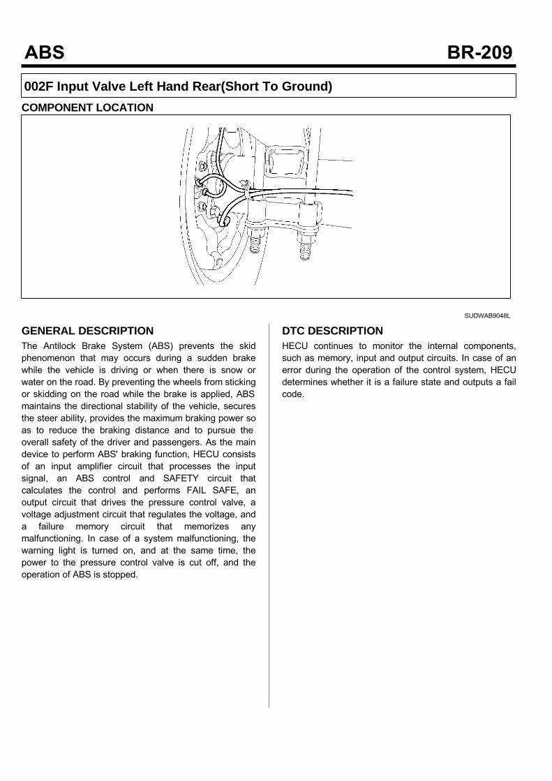
002F Input Valve Left Hand Rear(Short To Ground)COMPONENT LOCATION
SUDWAB9048L
GENERAL DESCRIPTIONThe Antilock Brake System (ABS) prevents the skidphenomenon that may occurs during a sudden brakewhile the vehicle is driving or when there is snow orwater on the road. By preventing the wheels from stickingor skidding on the road while the brake is applied, ABSmaintains the directional stability of the vehicle, securesthe steer ability, provides the maximum braking power soas to reduce the braking distance and to pursue theoverall safety of the driver and passengers. As the maindevice to perform ABS' braking function, HECU consistsof an input amplifier circuit that processes the inputsignal, an ABS control and SAFETY circuit thatcalculates the control and performs FAIL SAFE, anoutput circuit that drives the pressure control valve, avoltage adjustment circuit that regulates the voltage, anda failure memory circuit that memorizes anymalfunctioning. In case of a system malfunctioning, thewarning light is turned on, and at the same time, thepower to the pressure control valve is cut off, and theoperation of ABS is stopped.
DTC DESCRIPTIONHECU continues to monitor the internal components,such as memory, input and output circuits. In case of anerror during the operation of the control system, HECUdetermines whether it is a failure state and outputs a failcode.

DTC DETECTING CONDITIONItem Detecting Condition Possible Cause
DTC Strategy Signal monitoring • Replace ECU.
Enable Conditions Ignition ON
Threshold Value When the HECU detects malfunction in the control system
Diagnosis Time Below 1,000 ms
Fail Safe Fuel Cut No • ABS function temp-orarily disabled forconcerned wheel.
Fuel Limit Yes
MIL Yes
MONITOR SCAN TOOL DATA1. Connect the scan tool to the self-diagnosisconnector.
2. Turn the ignition ON.3. Select the data "Actuation test".
4. Check the left hand rear inlet valve for operationwhen activating the actuator. Specification: Normal if the activating sound isheard.
SUDWAB9034L
Fig1) Left hand rear inlet valve Actuation test at IGON
5. Does the valve activate normally?
There may be a transient trouble due to defectivevalve or a past trouble which did not erase thememory of HECU after having repair. And go to "Verification of Vehicle Repair”procedure.
Go to "Component Inspection" procedure.
TERMINAL & CONNECTOR INSPECTION1. Many malfunctions in the electrical system arecaused by poor harness, and terminals.Faults can also be caused by interference from otherelectrical systems, and mechanical or chemicaldamage.
2. Thoroughly check connectors for looseness, poorconnection, bent, corrosion, contamination,deterioration, or damage.
3. Has a problem been found?
Repair as necessary and then go to “Verification ofVehicle Repair” procedure.

Go to “Signal Circuit Inspection” procedure.
COMPONENT INSPECTION1. Start the engine.2. Drive the vehicle with approx. 15km/h or higher.3. Turn the ignition ON. Leave the engine OFF.4. Connect the scan tool and check the diagnostictrouble codes by using self-diagnosis.
5. Using the scan tool erase the diagnostic troublecodes stored in the HECU.
6. Check that there are any diagnostic trouble codes byusing self-diagnosis with the scan tool.
7. Are any diagnostic trouble codes (DTCs) detected?
Check that the DTCs have disappeared afterreplacing with a known-good HECU. If the problemhas solved, we may guess the HECU is problem.Replace the HECU and go to “Verification of VehicleRepair” procedure.
There may be a defective valve component or atransient trouble due to a past trouble which did noterase the memory of HECU after having repair. Andgo to "Verification of Vehicle Repair” procedure.
VERIFICATION OF VEHICLE REPAIRAfter a repair, it is essential to verify that the fault hasbeen corrected.1. Connect the scan tool and perform the self diagnosis.Check diagnostic trouble codes.
2. Clear the diagnostic trouble codes (DTCs) stored inthe ECM by using the scan tool.
3. Drive the vehicle under conditions noted in failurerecords.
4. Check that there are any DTCs by performing selfdiagnosis with the scan tool.
5. Did the DTC return?
Go to the applicable DTC procedure.
System OK

0030 Output Valve Left Hand Rear(Short To Ground)COMPONENT LOCATION
SUDWAB9048L
GENERAL DESCRIPTIONThe Antilock Brake System (ABS) prevents the skidphenomenon that may occurs during a sudden brakewhile the vehicle is driving or when there is snow orwater on the road. By preventing the wheels from stickingor skidding on the road while the brake is applied, ABSmaintains the directional stability of the vehicle, securesthe steer ability, provides the maximum braking power soas to reduce the braking distance and to pursue theoverall safety of the driver and passengers. As the maindevice to perform ABS' braking function, HECU consistsof an input amplifier circuit that processes the inputsignal, an ABS control and SAFETY circuit thatcalculates the control and performs FAIL SAFE, anoutput circuit that drives the pressure control valve, avoltage adjustment circuit that regulates the voltage, anda failure memory circuit that memorizes anymalfunctioning. In case of a system malfunctioning, thewarning light is turned on, and at the same time, thepower to the pressure control valve is cut off, and theoperation of ABS is stopped.
DTC DESCRIPTIONHECU continues to monitor the internal components,such as memory, input and output circuits. In case of anerror during the operation of the control system, HECUdetermines whether it is a failure state and outputs a failcode.
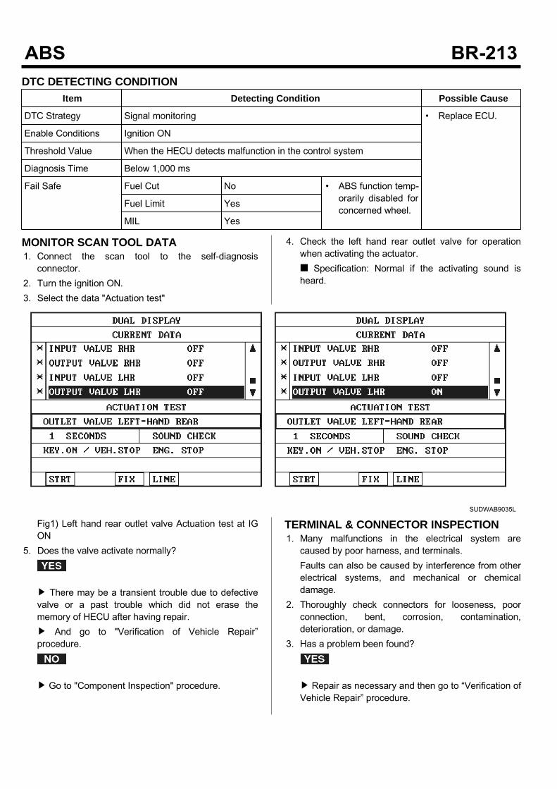
DTC DETECTING CONDITIONItem Detecting Condition Possible Cause
DTC Strategy Signal monitoring • Replace ECU.
Enable Conditions Ignition ON
Threshold Value When the HECU detects malfunction in the control system
Diagnosis Time Below 1,000 ms
Fail Safe Fuel Cut No • ABS function temp-orarily disabled forconcerned wheel.
Fuel Limit Yes
MIL Yes
MONITOR SCAN TOOL DATA1. Connect the scan tool to the self-diagnosisconnector.
2. Turn the ignition ON.3. Select the data "Actuation test"
4. Check the left hand rear outlet valve for operationwhen activating the actuator. Specification: Normal if the activating sound isheard.
SUDWAB9035L
Fig1) Left hand rear outlet valve Actuation test at IGON
5. Does the valve activate normally?
There may be a transient trouble due to defectivevalve or a past trouble which did not erase thememory of HECU after having repair. And go to "Verification of Vehicle Repair”procedure.
Go to "Component Inspection" procedure.
TERMINAL & CONNECTOR INSPECTION1. Many malfunctions in the electrical system arecaused by poor harness, and terminals.Faults can also be caused by interference from otherelectrical systems, and mechanical or chemicaldamage.
2. Thoroughly check connectors for looseness, poorconnection, bent, corrosion, contamination,deterioration, or damage.
3. Has a problem been found?
Repair as necessary and then go to “Verification ofVehicle Repair” procedure.

Go to “Signal Circuit Inspection” procedure.
COMPONENT INSPECTION1. Start the engine.2. Drive the vehicle with approx. 15km/h or higher.3. Turn the ignition ON. Leave the engine OFF.4. Connect the scan tool and check the diagnostictrouble codes by using self-diagnosis.
5. Using the scan tool erase the diagnostic troublecodes stored in the HECU.
6. Check that there are any diagnostic trouble codes byusing self-diagnosis with the scan tool.
7. Are any diagnostic trouble codes (DTCs) detected?
Check that the DTCs have disappeared afterreplacing with a known-good HECU. If the problemhas solved, we may guess the HECU is problem.Replace the HECU and go to “Verification of VehicleRepair” procedure.
There may be a defective valve component or atransient trouble due to a past trouble which did noterase the memory of HECU after having repair. Andgo to "Verification of Vehicle Repair” procedure.
VERIFICATION OF VEHICLE REPAIRAfter a repair, it is essential to verify that the fault hasbeen corrected.1. Connect the scan tool and perform the self diagnosis.Check diagnostic trouble codes.
2. Clear the diagnostic trouble codes (DTCs) stored inthe ECM by using the scan tool.
3. Drive the vehicle under conditions noted in failurerecords.
4. Check that there are any DTCs by performing selfdiagnosis with the scan tool.
5. Did the DTC return?
Go to the applicable DTC procedure.
System OK
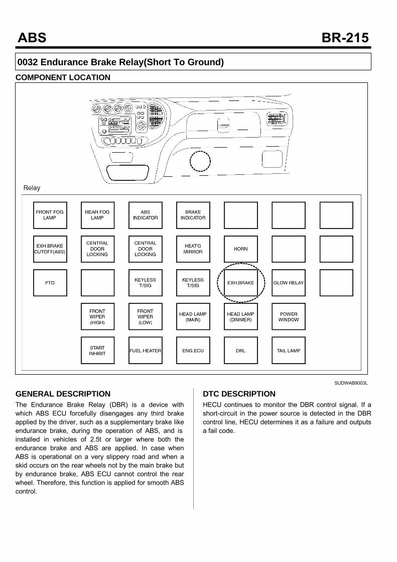
0032 Endurance Brake Relay(Short To Ground)COMPONENT LOCATION
SUDWAB9003L
GENERAL DESCRIPTIONThe Endurance Brake Relay (DBR) is a device withwhich ABS ECU forcefully disengages any third brakeapplied by the driver, such as a supplementary brake likeendurance brake, during the operation of ABS, and isinstalled in vehicles of 2.5t or larger where both theendurance brake and ABS are applied. In case whenABS is operational on a very slippery road and when askid occurs on the rear wheels not by the main brake butby endurance brake, ABS ECU cannot control the rearwheel. Therefore, this function is applied for smooth ABScontrol.
DTC DESCRIPTIONHECU continues to monitor the DBR control signal. If ashort-circuit in the power source is detected in the DBRcontrol line, HECU determines it as a failure and outputsa fail code.
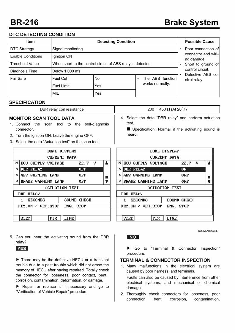
DTC DETECTING CONDITIONItem Detecting Condition Possible Cause
DTC Strategy Signal monitoring • Poor connection ofconnector and wiri-ng damage.
• Short to ground ofcontrol circuit.
• Defective ABS co-ntrol relay.
Enable Conditions Ignition ON
Threshold Value When short to the control circuit of ABS relay is detected
Diagnosis Time Below 1,000 ms
Fail Safe Fuel Cut No • The ABS functionworks normally.Fuel Limit Yes
MIL Yes
SPECIFICATIONDBR relay coil resistance 200 ~ 450 Ω (At 20)
MONITOR SCAN TOOL DATA1. Connect the scan tool to the self-diagnosisconnector.
2. Turn the ignition ON. Leave the engine OFF.3. Select the data "Actuation test" on the scan tool.
4. Select the data “DBR relay” and perform actuationtest. Specification: Normal if the activating sound isheard.
SUDWAB9036L
5. Can you hear the activating sound from the DBRrelay?
There may be the defective HECU or a transienttrouble due to a past trouble which did not erase thememory of HECU after having repaired. Totally checkthe connector for looseness, poor contact, bent,corrosion, contamination, deformation, or damage. Repair or replace it if necessary and go to"Verification of Vehicle Repair” procedure.
Go to “Terminal & Connector Inspection”procedure.
TERMINAL & CONNECTOR INSPECTION1. Many malfunctions in the electrical system arecaused by poor harness, and terminals.Faults can also be caused by interference from otherelectrical systems, and mechanical or chemicaldamage.
2. Thoroughly check connectors for looseness, poorconnection, bent, corrosion, contamination,
deterioration, or damage.3. Has a problem been found?
Repair as necessary and then go to “Verification ofVehicle Repair” procedure.
Go to “Signal Circuit Inspection” procedure.
CONTROL CIRCUIT INSPECTIONControl Short to Ground Inspection1. Turn the ignition OFF.2. Disconnect the DBR relay connector (M15) andHECU connector (C60).
3. Measure the resistance between the terminal 3 ofDBR relay harness connector (M15) and chassisground. Specification: Infinite
4. Is the resistance measured within specification?
Go to “Component Inspection” procedure.
Repair short to ground between terminal of HECUharness connector and terminal of DBR relay controland go to “Verification of Vehicle Repair” procedure.
COMPONENT INSPECTION1. Turn the ignition OFF.2. Disconnect the DBR relay connector (M15).3. Measure the resistance between terminals 3 and 5 ofDBR relay component. Specification: DBR relay coil resistance: 200 ~450 Ω (At 20)
4. Measure the resistance between terminals 1 and 4 ofDBR relay while applying and cutting off B+ power toterminals 3 and 5 of DBR relay. Specification:Continuity (When applying power)Infinite (When cutting off power)
5. Is the resistance measured within specification?
Go to "Verification of Vehicle Repair” procedure.
Replace the relay and go to "Verification ofVehicle Repair” procedure. Repeat "Component Inspection" procedure severaltimes.
VERIFICATION OF VEHICLE REPAIRAfter a repair, it is essential to verify that the fault hasbeen corrected.1. Connect the scan tool and perform the self diagnosis.Check diagnostic trouble codes.
2. Clear the diagnostic trouble codes (DTCs) stored inthe ECM by using the scan tool.
3. Drive the vehicle under conditions noted in failurerecords.
4. Check that there are any DTCs by performing selfdiagnosis with the scan tool.
5. Did the DTC return?
Go to the applicable DTC procedure.
System OK
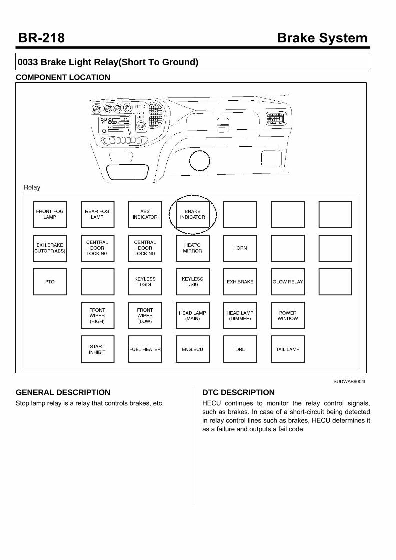
0033 Brake Light Relay(Short To Ground)COMPONENT LOCATION
SUDWAB9004L
GENERAL DESCRIPTIONStop lamp relay is a relay that controls brakes, etc.
DTC DESCRIPTIONHECU continues to monitor the relay control signals,such as brakes. In case of a short-circuit being detectedin relay control lines such as brakes, HECU determines itas a failure and outputs a fail code.

DTC DETECTING CONDITIONItem Detecting Condition Possible Cause
DTC Strategy Signal monitoring • Poor contact of co-nnector and wiringdamage.
• Short to ground ofcontrol circuit.
• Defective brake lig-ht relay.
Enable Conditions Ignition ON
Threshold Value When the brake light relay control circuit is short
Diagnosis Time Below 1,000 ms
Fail Safe Fuel Cut No • The ABS functionworks normally.Fuel Limit Yes
MIL Yes
SPECIFICATIONBrake light relay coil resistance 200 ~ 450 Ω (At 20)
MONITOR SCAN TOOL DATA1. Connect the scan tool to the self-diagnosisconnector.
2. Turn the ignition ON. Leave the engine OFF.3. Select the data "Actuation test" on the scan tool.
4. Select the data “Brake light relay” and performactuation test. Specification: Normal if the activating sound isheard.
SUDWAB9037L
5. Can you hear the activating sound from the brakelight relay?
There may be the defective HECU or a transienttrouble due to a past trouble which did not erase thememory of HECU after having repaired. Totally checkthe connector for looseness, poor contact, bent,corrosion, contamination, deformation, or damage. Repair or replace it if necessary and go to"Verification of Vehicle Repair” procedure.
Go to “Terminal & Connector Inspection”procedure.
TERMINAL & CONNECTOR INSPECTION1. Many malfunctions in the electrical system arecaused by poor harness, and terminals.Faults can also be caused by interference from otherelectrical systems, and mechanical or chemicaldamage.
2. Thoroughly check connectors for looseness, poorconnection, bent, corrosion, contamination,
deterioration, or damage.3. Has a problem been found?
Repair as necessary and then go to “Verification ofVehicle Repair” procedure.
Go to “Signal Circuit Inspection” procedure.
CONTROL CIRCUIT INSPECTIONShort to Control Power Inspection1. Turn the ignition OFF.2. Disconnect the brake light relay (M102) and HECUconnector (C60).
3. Measure the resistance between the terminal 3 ofbrake light relay harness connector (M102) andchassis ground. Specification: Infinite
4. Is the resistance measured within specification?
Go to “Component Inspection” procedure.
Repair short to control circuit between terminal ofHECU harness connector and terminal of brake lightrelay control harness and go to “Verification ofVehicle Repair” procedure.
COMPONENT INSPECTION1. Turn the ignition OFF.2. Disconnect the brake light relay connector (M102).3. Measure the resistance between terminals 3 and 5 ofABS light relay component. Specification: Brake light relay coil resistance: 200~ 450 Ω (At 20)
4. Measure the resistance between terminals 1 and 4 ofbrake light relay while applying and cutting off B+power to terminals 3 and 5 of ABS light relay. Specification:Continuity (When applying power)Infinite (When cutting off power)
5. Is the resistance measured within specification?
Go to "Verification of Vehicle Repair” procedure.
Replace the relay and go to "Verification ofVehicle Repair” procedure. Repeat "Component Inspection" procedure severaltimes.
VERIFICATION OF VEHICLE REPAIRAfter a repair, it is essential to verify that the fault hasbeen corrected.1. Connect the scan tool and perform the self diagnosis.Check diagnostic trouble codes.
2. Clear the diagnostic trouble codes (DTCs) stored inthe ECM by using the scan tool.
3. Drive the vehicle under conditions noted in failurerecords.
4. Check that there are any DTCs by performing selfdiagnosis with the scan tool.
5. Did the DTC return?
Go to the applicable DTC procedure.
System OK
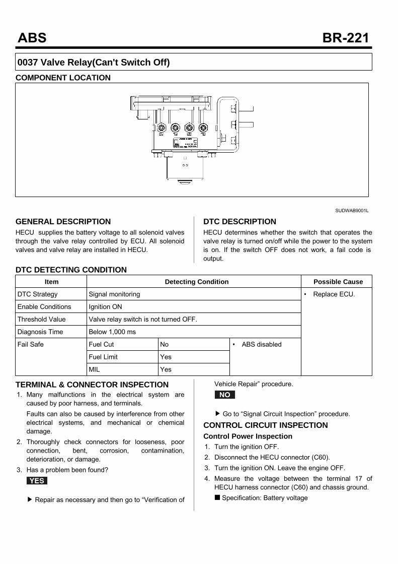
0037 Valve Relay(Can't Switch Off)COMPONENT LOCATION
SUDWAB9001L
GENERAL DESCRIPTIONHECU supplies the battery voltage to all solenoid valvesthrough the valve relay controlled by ECU. All solenoidvalves and valve relay are installed in HECU.
DTC DESCRIPTIONHECU determines whether the switch that operates thevalve relay is turned on/off while the power to the systemis on. If the switch OFF does not work, a fail code isoutput.
DTC DETECTING CONDITIONItem Detecting Condition Possible Cause
DTC Strategy Signal monitoring • Replace ECU.
Enable Conditions Ignition ON
Threshold Value Valve relay switch is not turned OFF.
Diagnosis Time Below 1,000 ms
Fail Safe Fuel Cut No • ABS disabled
Fuel Limit Yes
MIL Yes
TERMINAL & CONNECTOR INSPECTION1. Many malfunctions in the electrical system arecaused by poor harness, and terminals.Faults can also be caused by interference from otherelectrical systems, and mechanical or chemicaldamage.
2. Thoroughly check connectors for looseness, poorconnection, bent, corrosion, contamination,deterioration, or damage.
3. Has a problem been found?
Repair as necessary and then go to “Verification of
Vehicle Repair” procedure.
Go to “Signal Circuit Inspection” procedure.
CONTROL CIRCUIT INSPECTIONControl Power Inspection1. Turn the ignition OFF.2. Disconnect the HECU connector (C60).3. Turn the ignition ON. Leave the engine OFF.4. Measure the voltage between the terminal 17 ofHECU harness connector (C60) and chassis ground. Specification: Battery voltage

5. Is the voltage measured within specification?
Go to “Ground Circuit Inspection” procedure.
Check the fuse 30A. If it is burnt, replace it. Whenthe fuse is normal, check open of terminal 17 of ABScontrol module harness connector and short toground. Repair it if there is any problem and go to“Verification of Vehicle Repair” procedure.
GROUND CIRCUIT INSPECTION1. Turn the ignition OFF.2. Disconnect the HECU connector (C60).3. Measure the resistance between the terminals 18, 19of HECU harness connector (C60) and chassisground. Specification: Continuity
4. Is the resistance measured within specification?
Go to “Component Inspection” procedure.
Check open or poor contact between the solenoidvalve ground of ABS control module harnessconnector and chassis ground. And go to "Verificationof Vehicle Repair” procedure.
COMPONENT INSPECTION1. Start the engine.2. Drive the vehicle with approx. 15km/h or higher.3. Turn the ignition ON. Leave the engine OFF.4. Connect the scan tool and check the diagnostictrouble codes by using self-diagnosis.
5. Using the scan tool erase the diagnostic troublecodes stored in the HECU.
6. Check that there are any diagnostic trouble codes byusing self-diagnosis with the scan tool.
7. Are any diagnostic trouble codes (DTCs) detected?
Check that the DTCs have disappeared afterreplacing with a known-good HECU. If the problemhas solved, we may guess the HECU is problem.Replace the HECU and go to “Verification of VehicleRepair” procedure.
There may be a defective valve component or atransient trouble due to a past trouble which did noterase the memory of HECU after having repair. Andgo to "Verification of Vehicle Repair” procedure.
VERIFICATION OF VEHICLE REPAIRAfter a repair, it is essential to verify that the fault hasbeen corrected.1. Connect the scan tool and perform the self diagnosis.Check diagnostic trouble codes.
2. Clear the diagnostic trouble codes (DTCs) stored inthe ECM by using the scan tool.
3. Drive the vehicle under conditions noted in failurerecords.
4. Check that there are any DTCs by performing selfdiagnosis with the scan tool.
5. Did the DTC return?
Go to the applicable DTC procedure.
System OK

0038 Valve Relay(Can't Switch On)COMPONENT LOCATION
SUDWAB9001L
GENERAL DESCRIPTIONHECU supplies the battery voltage to all solenoid valvesthrough the valve relay controlled by ECU. All solenoidvalves and valve relay are installed in HECU.
DTC DESCRIPTIONHECU determines whether the switch that operates thevalve relay is turned on/off while the power to the systemis on. If the switch ON does not work, a fail code isoutput.
DTC DETECTING CONDITIONItem Detecting Condition Possible Cause
DTC Strategy Signal monitoring • Replace ECU.
Enable Conditions Ignition ON
Threshold Value Valve relay switch is not turned ON.
Diagnosis Time Below 1,000 ms
Fail Safe Fuel Cut No • ABS disabled
Fuel Limit Yes
MIL Yes
TERMINAL & CONNECTOR INSPECTION1. Many malfunctions in the electrical system arecaused by poor harness, and terminals.Faults can also be caused by interference from otherelectrical systems, and mechanical or chemicaldamage.
2. Thoroughly check connectors for looseness, poorconnection, bent, corrosion, contamination,deterioration, or damage.
3. Has a problem been found?
Repair as necessary and then go to “Verification of
Vehicle Repair” procedure.
Go to “Signal Circuit Inspection” procedure.
CONTROL CIRCUIT INSPECTIONControl Power Inspection1. Turn the ignition OFF.2. Disconnect the HECU connector (C60).3. Turn the ignition ON. Leave the engine OFF.4. Measure the voltage between the terminal 17 ofHECU harness connector (C60) and chassis ground. Specification: Battery voltage
5. Is the voltage measured within specification?
Go to “Ground Circuit Inspection” procedure.
Check the fuse 30A. If it is burnt, replace it. Whenthe fuse is normal, check open of terminal 17 of ABScontrol module harness connector and short toground. Repair it if there is any problem and go to“Verification of Vehicle Repair” procedure.
GROUND CIRCUIT INSPECTION1. Turn the ignition OFF.2. Disconnect the HECU connector (C60).3. Measure the resistance between the terminals 18, 19of HECU harness connector (C60) and chassisground. Specification: Continuity
4. Is the resistance measured within specification?
Go to “Component Inspection” procedure.
Check open or poor contact between the solenoidvalve ground of ABS control module harnessconnector and chassis ground. And go to "Verificationof Vehicle Repair” procedure.
COMPONENT INSPECTION1. Start the engine.2. Drive the vehicle with approx. 15km/h or higher.3. Turn the ignition ON. Leave the engine OFF.4. Connect the scan tool and check the diagnostictrouble codes by using self-diagnosis.
5. Using the scan tool erase the diagnostic troublecodes stored in the HECU.
6. Check that there are any diagnostic trouble codes byusing self-diagnosis with the scan tool.
7. Are any diagnostic trouble codes (DTCs) detected?
Check that the DTCs have disappeared afterreplacing with a known-good HECU. If the problemhas solved, we may guess the HECU is problem.Replace the HECU and go to “Verification of VehicleRepair” procedure.
There may be a defective valve component or atransient trouble due to a past trouble which did noterase the memory of HECU after having repair. Andgo to "Verification of Vehicle Repair” procedure.
VERIFICATION OF VEHICLE REPAIRAfter a repair, it is essential to verify that the fault hasbeen corrected.1. Connect the scan tool and perform the self diagnosis.Check diagnostic trouble codes.
2. Clear the diagnostic trouble codes (DTCs) stored inthe ECM by using the scan tool.
3. Drive the vehicle under conditions noted in failurerecords.
4. Check that there are any DTCs by performing selfdiagnosis with the scan tool.
5. Did the DTC return?
Go to the applicable DTC procedure.
System OK
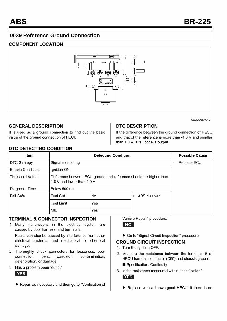
0039 Reference Ground ConnectionCOMPONENT LOCATION
SUDWAB9001L
GENERAL DESCRIPTIONIt is used as a ground connection to find out the basicvalue of the ground connection of HECU.
DTC DESCRIPTIONIf the difference between the ground connection of HECUand that of the reference is more than -1.6 V and smallerthan 1.0 V, a fail code is output.
DTC DETECTING CONDITIONItem Detecting Condition Possible Cause
DTC Strategy Signal monitoring • Replace ECU.
Enable Conditions Ignition ON
Threshold Value Difference between ECU ground and reference should be higher than -1.6 V and lower than 1.0 V
Diagnosis Time Below 500 ms
Fail Safe Fuel Cut No • ABS disabled
Fuel Limit Yes
MIL Yes
TERMINAL & CONNECTOR INSPECTION1. Many malfunctions in the electrical system arecaused by poor harness, and terminals.Faults can also be caused by interference from otherelectrical systems, and mechanical or chemicaldamage.
2. Thoroughly check connectors for looseness, poorconnection, bent, corrosion, contamination,deterioration, or damage.
3. Has a problem been found?
Repair as necessary and then go to “Verification of
Vehicle Repair” procedure.
Go to “Signal Circuit Inspection” procedure.
GROUND CIRCUIT INSPECTION1. Turn the ignition OFF.2. Measure the resistance between the terminals 6 ofHECU harness connector (C60) and chassis ground. Specification: Continuity
3. Is the resistance measured within specification?
Replace with a known-good HECU. If there is no
problem, replace the HECU and go to "Verification ofVehicle Repair” procedure.
Repair open between the reference ground of ABScontrol module harness connector and chassisground and check poor contact. If there is anyproblem repair poor contact. And go to "Verificationof Vehicle Repair” procedure.
VERIFICATION OF VEHICLE REPAIRAfter a repair, it is essential to verify that the fault hasbeen corrected.1. Connect the scan tool and perform the self diagnosis.Check diagnostic trouble codes.
2. Clear the diagnostic trouble codes (DTCs) stored inthe ECM by using the scan tool.
3. Drive the vehicle under conditions noted in failurerecords.
4. Check that there are any DTCs by performing selfdiagnosis with the scan tool.
5. Did the DTC return?
Go to the applicable DTC procedure.
System OK
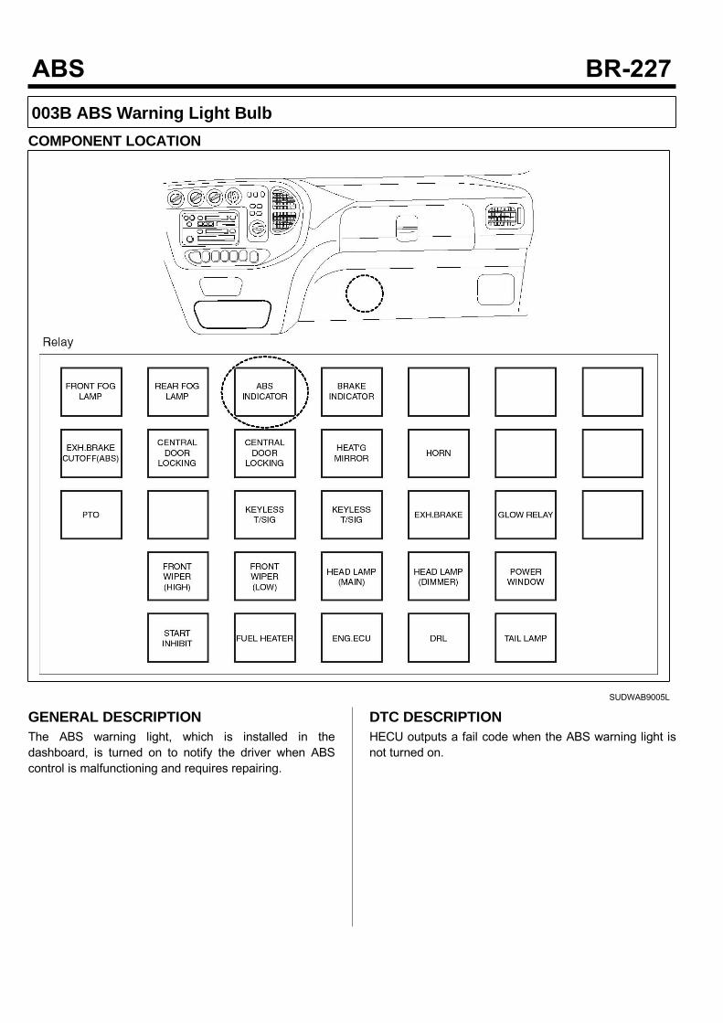
003B ABS Warning Light BulbCOMPONENT LOCATION
SUDWAB9005L
GENERAL DESCRIPTIONThe ABS warning light, which is installed in thedashboard, is turned on to notify the driver when ABScontrol is malfunctioning and requires repairing.
DTC DESCRIPTIONHECU outputs a fail code when the ABS warning light isnot turned on.
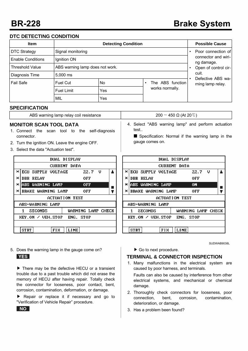
DTC DETECTING CONDITIONItem Detecting Condition Possible Cause
DTC Strategy Signal monitoring • Poor connection ofconnector and wiri-ng damage.
• Open of control cir-cuit.
• Defective ABS wa-rning lamp relay.
Enable Conditions Ignition ON
Threshold Value ABS warning lamp does not work.
Diagnosis Time 5,000 ms
Fail Safe Fuel Cut No • The ABS functionworks normally.Fuel Limit Yes
MIL Yes
SPECIFICATIONABS warning lamp relay coil resistance 200 ~ 450 Ω (At 20)
MONITOR SCAN TOOL DATA1. Connect the scan tool to the self-diagnosisconnector.
2. Turn the ignition ON. Leave the engine OFF.3. Select the data "Actuation test".
4. Select "ABS warning lamp" and perform actuationtest.. Specification: Normal if the warning lamp in thegauge comes on.
SUDWAB9038L
5. Does the warning lamp in the gauge come on?
There may be the defective HECU or a transienttrouble due to a past trouble which did not erase thememory of HECU after having repair. Totally checkthe connector for looseness, poor contact, bent,corrosion, contamination, deformation, or damage. Repair or replace it if necessary and go to"Verification of Vehicle Repair” procedure.
Go to next procedure.
TERMINAL & CONNECTOR INSPECTION1. Many malfunctions in the electrical system arecaused by poor harness, and terminals.Faults can also be caused by interference from otherelectrical systems, and mechanical or chemicaldamage.
2. Thoroughly check connectors for looseness, poorconnection, bent, corrosion, contamination,deterioration, or damage.
3. Has a problem been found?
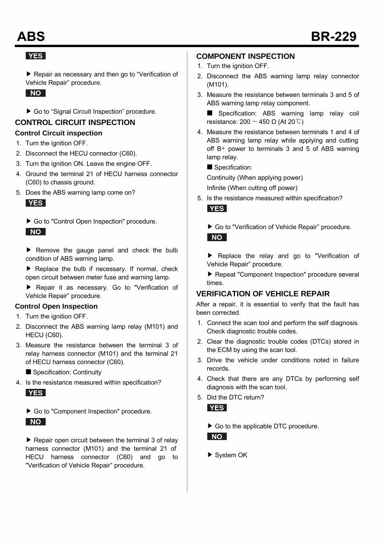
Repair as necessary and then go to “Verification ofVehicle Repair” procedure.
Go to “Signal Circuit Inspection” procedure.
CONTROL CIRCUIT INSPECTIONControl Circuit inspection1. Turn the ignition OFF.2. Disconnect the HECU connector (C60).3. Turn the ignition ON. Leave the engine OFF.4. Ground the terminal 21 of HECU harness connector(C60) to chassis ground.
5. Does the ABS warning lamp come on?
Go to "Control Open Inspection" procedure.
Remove the gauge panel and check the bulbcondition of ABS warning lamp. Replace the bulb if necessary. If normal, checkopen circuit between meter fuse and warning lamp. Repair it as necessary. Go to "Verification ofVehicle Repair” procedure.
Control Open Inspection1. Turn the ignition OFF.2. Disconnect the ABS warning lamp relay (M101) andHECU (C60).
3. Measure the resistance between the terminal 3 ofrelay harness connector (M101) and the terminal 21of HECU harness connector (C60). Specification: Continuity
4. Is the resistance measured within specification?
Go to "Component Inspection" procedure.
Repair open circuit between the terminal 3 of relayharness connector (M101) and the terminal 21 ofHECU harness connector (C60) and go to"Verification of Vehicle Repair” procedure.
COMPONENT INSPECTION1. Turn the ignition OFF.2. Disconnect the ABS warning lamp relay connector(M101).
3. Measure the resistance between terminals 3 and 5 ofABS warning lamp relay component. Specification: ABS warning lamp relay coilresistance: 200 ~ 450 Ω (At 20)
4. Measure the resistance between terminals 1 and 4 ofABS warning lamp relay while applying and cuttingoff B+ power to terminals 3 and 5 of ABS warninglamp relay. Specification:Continuity (When applying power)Infinite (When cutting off power)
5. Is the resistance measured within specification?
Go to "Verification of Vehicle Repair” procedure.
Replace the relay and go to "Verification ofVehicle Repair” procedure. Repeat "Component Inspection" procedure severaltimes.
VERIFICATION OF VEHICLE REPAIRAfter a repair, it is essential to verify that the fault hasbeen corrected.1. Connect the scan tool and perform the self diagnosis.Check diagnostic trouble codes.
2. Clear the diagnostic trouble codes (DTCs) stored inthe ECM by using the scan tool.
3. Drive the vehicle under conditions noted in failurerecords.
4. Check that there are any DTCs by performing selfdiagnosis with the scan tool.
5. Did the DTC return?
Go to the applicable DTC procedure.
System OK
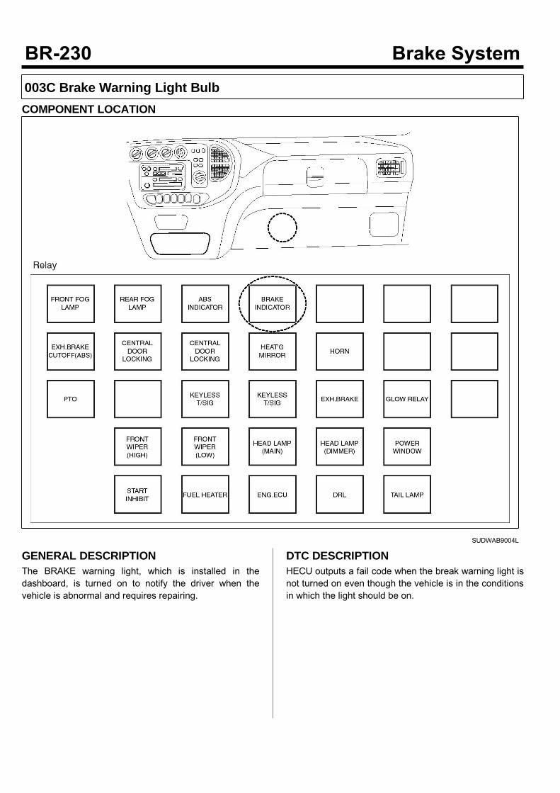
003C Brake Warning Light BulbCOMPONENT LOCATION
SUDWAB9004L
GENERAL DESCRIPTIONThe BRAKE warning light, which is installed in thedashboard, is turned on to notify the driver when thevehicle is abnormal and requires repairing.
DTC DESCRIPTIONHECU outputs a fail code when the break warning light isnot turned on even though the vehicle is in the conditionsin which the light should be on.
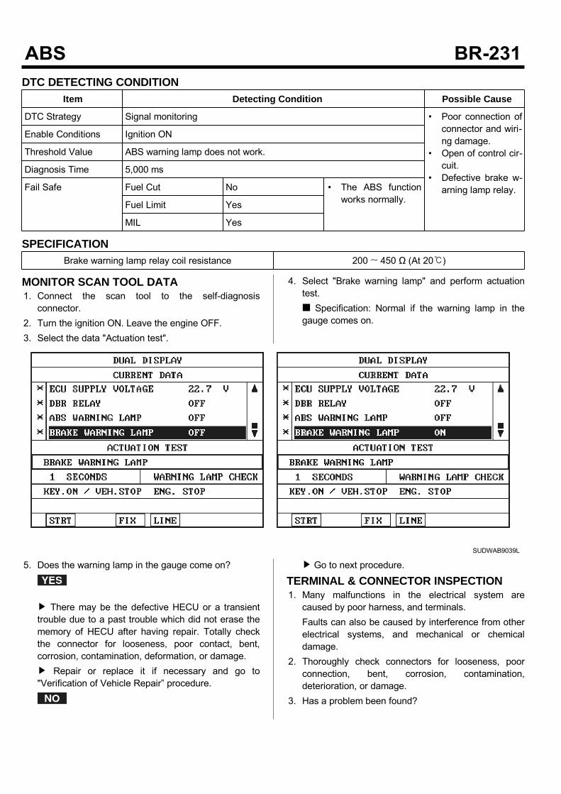
DTC DETECTING CONDITIONItem Detecting Condition Possible Cause
DTC Strategy Signal monitoring • Poor connection ofconnector and wiri-ng damage.
• Open of control cir-cuit.
• Defective brake w-arning lamp relay.
Enable Conditions Ignition ON
Threshold Value ABS warning lamp does not work.
Diagnosis Time 5,000 ms
Fail Safe Fuel Cut No • The ABS functionworks normally.Fuel Limit Yes
MIL Yes
SPECIFICATIONBrake warning lamp relay coil resistance 200 ~ 450 Ω (At 20)
MONITOR SCAN TOOL DATA1. Connect the scan tool to the self-diagnosisconnector.
2. Turn the ignition ON. Leave the engine OFF.3. Select the data "Actuation test".
4. Select "Brake warning lamp" and perform actuationtest. Specification: Normal if the warning lamp in thegauge comes on.
SUDWAB9039L
5. Does the warning lamp in the gauge come on?
There may be the defective HECU or a transienttrouble due to a past trouble which did not erase thememory of HECU after having repair. Totally checkthe connector for looseness, poor contact, bent,corrosion, contamination, deformation, or damage. Repair or replace it if necessary and go to"Verification of Vehicle Repair” procedure.
Go to next procedure.
TERMINAL & CONNECTOR INSPECTION1. Many malfunctions in the electrical system arecaused by poor harness, and terminals.Faults can also be caused by interference from otherelectrical systems, and mechanical or chemicaldamage.
2. Thoroughly check connectors for looseness, poorconnection, bent, corrosion, contamination,deterioration, or damage.
3. Has a problem been found?
Repair as necessary and then go to “Verification ofVehicle Repair” procedure.
Go to “Signal Circuit Inspection” procedure.
CONTROL CIRCUIT INSPECTIONControl Circuit inspection1. Turn the ignition OFF.2. Disconnect the HECU connector (C60).3. Turn the ignition ON. Leave the engine OFF.4. Ground the terminal 21 of HECU harness connector(C60) to chassis ground.
5. Does the brake warning lamp come on?
Go to "Control Open Inspection" procedure.
Remove the gauge panel and check the bulbcondition of brake warning lamp. Replace the bulb if necessary. If normal, checkopen circuit between meter fuse and warning lamp. Repair it as necessary. Go to "Verification ofVehicle Repair” procedure.
Control Open Inspection1. Turn the ignition OFF.2. Disconnect the brake warning lamp relay (M102) andHECU (C60).
3. Measure the resistance between the terminal 3 ofrelay connector (M102) and the terminal 21 of HECUharness connector (C60). Specification: Continuity
4. Is the resistance measured within specification?
Go to "Component Inspection" procedure.
Repair open circuit between terminal of HECUharness connector and terminal of brake warninglamp relay control harness connector and go to"Verification of Vehicle Repair” procedure.
COMPONENT INSPECTION1. Turn the ignition OFF.2. Disconnect the brake warning lamp relay connector(M102).
3. Measure the resistance between terminals 3 and 5 ofbrake warning lamp relay component. Specification: Brake warning lamp relay coilresistance: 200 ~ 450 Ω (At 20)
4. Measure the resistance between terminals 1 and 4while applying and cutting off B+ power to terminals 3and 5 of brake warning lamp relay. Specification:Continuity (When applying power)Infinite (When cutting off power)
5. Is the resistance measured within specification?
Go to "Verification of Vehicle Repair” procedure.
Replace the relay and go to "Verification ofVehicle Repair” procedure. Repeat "Component Inspection" procedure severaltimes.
VERIFICATION OF VEHICLE REPAIRAfter a repair, it is essential to verify that the fault hasbeen corrected.1. Connect the scan tool and perform the self diagnosis.Check diagnostic trouble codes.
2. Clear the diagnostic trouble codes (DTCs) stored inthe ECM by using the scan tool.
3. Drive the vehicle under conditions noted in failurerecords.
4. Check that there are any DTCs by performing selfdiagnosis with the scan tool.
5. Did the DTC return?
Go to the applicable DTC procedure.
System OK
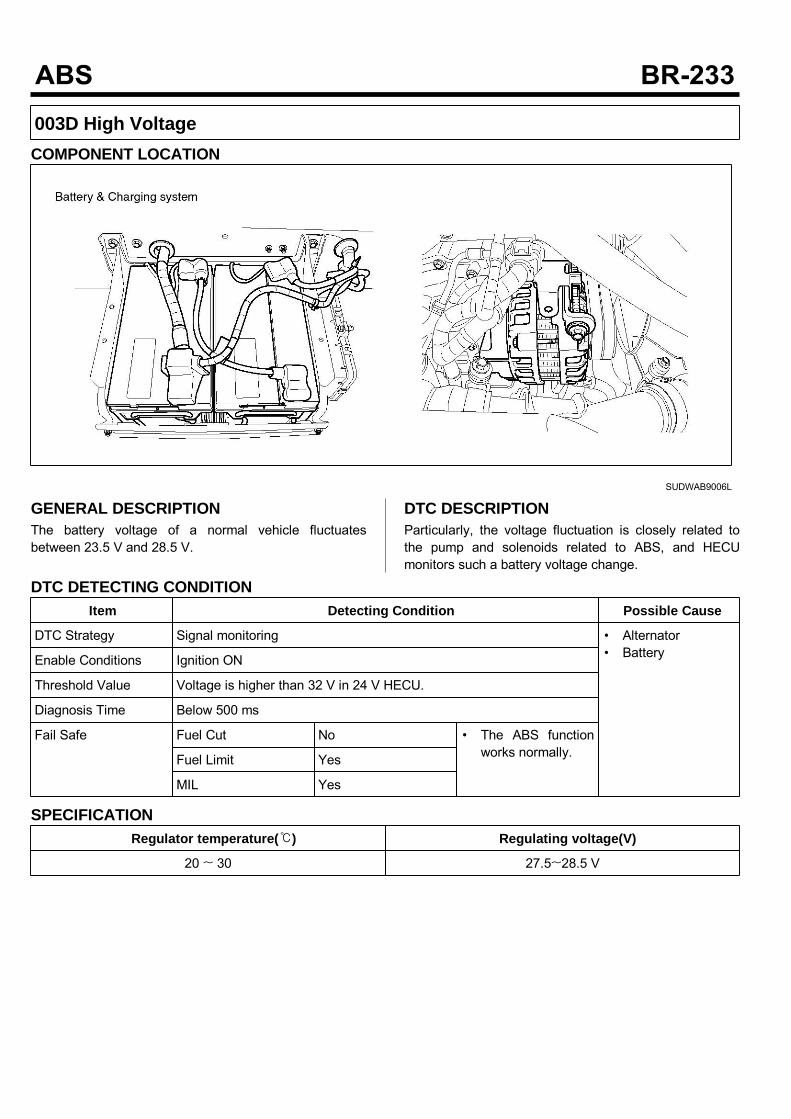
003D High VoltageCOMPONENT LOCATION
SUDWAB9006L
GENERAL DESCRIPTIONThe battery voltage of a normal vehicle fluctuatesbetween 23.5 V and 28.5 V.
DTC DESCRIPTIONParticularly, the voltage fluctuation is closely related tothe pump and solenoids related to ABS, and HECUmonitors such a battery voltage change.
DTC DETECTING CONDITIONItem Detecting Condition Possible Cause
DTC Strategy Signal monitoring • Alternator• BatteryEnable Conditions Ignition ON
Threshold Value Voltage is higher than 32 V in 24 V HECU.
Diagnosis Time Below 500 ms
Fail Safe Fuel Cut No • The ABS functionworks normally.Fuel Limit Yes
MIL Yes
SPECIFICATIONRegulator temperature() Regulating voltage(V)
20 ~ 30 27.5~28.5 V
TERMINAL & CONNECTOR INSPECTION1. Many malfunctions in the electrical system arecaused by poor harness, and terminals.Faults can also be caused by interference from otherelectrical systems, and mechanical or chemicaldamage.
2. Thoroughly check connectors for looseness, poorconnection, bent, corrosion, contamination,deterioration, or damage.
3. Has a problem been found?
Repair as necessary and then go to “Verification ofVehicle Repair” procedure.
Go to “Signal Circuit Inspection” procedure.
CONTROL CIRCUIT INSPECTIONAlternator Connector Supply Power Inspection1. Leave the alternator connector connected.2. Turn the ignition ON. Leave the engine ON.3. Measure the voltage of terminal 1 of alternatorconnector. Specification: Charging voltage B+ V
4. Is the voltage measured within specification?
Go to "Verification of Vehicle Repair” procedure.
Go to "Alternator B+ Cable Voltage DropInspection" procedure.
Alternator B+ Cable Voltage Drop Inspection1. Run the engine.2. Measure the voltage drop between the terminal ofalternator B+ and the terminal of battery B+.(Connect terminal + (positive) of multi-meter toterminal B+ of alternator, terminal - (negative) ofmulti-meter to terminal B+ of battery.) Specification: Within 200 mV
3. Is the voltage drop measured within specification?
Go to "Component Inspection" procedure.
Check the corrosion and degradation of alternatorB+ cable terminal and replace the cable asnecessary.
COMPONENT INSPECTIONAlternator Charging Voltage Inspection1. Turn the ignition OFF. Leave the engine OFF.2. Check the belt tension of alternator.3. Check battery terminal, fusible link, alternator B+terminal for looseness and corrosion.
4. Start the engine.5. Operate electric system such as head lamp, hot-wire,blower motor etc.
6. Specification:
Regulator temperature() Regulating voltage(V)
20 ~ 30 25.5~26.5 V
Measure battery voltage at engine 750 rpm or higher.7. Is the voltage measured within specification?
Go to "Verification of Vehicle Repair" procedure.
Replace the regulator and go to "Verification ofVehicle Repair" procedure.
VERIFICATION OF VEHICLE REPAIRAfter a repair, it is essential to verify that the fault hasbeen corrected.1. Connect the scan tool and perform the self diagnosis.Check diagnostic trouble codes.
2. Clear the diagnostic trouble codes (DTCs) stored inthe ECM by using the scan tool.
3. Drive the vehicle under conditions noted in failurerecords.
4. Check that there are any DTCs by performing selfdiagnosis with the scan tool.
5. Did the DTC return?
Go to the applicable DTC procedure.
System OK
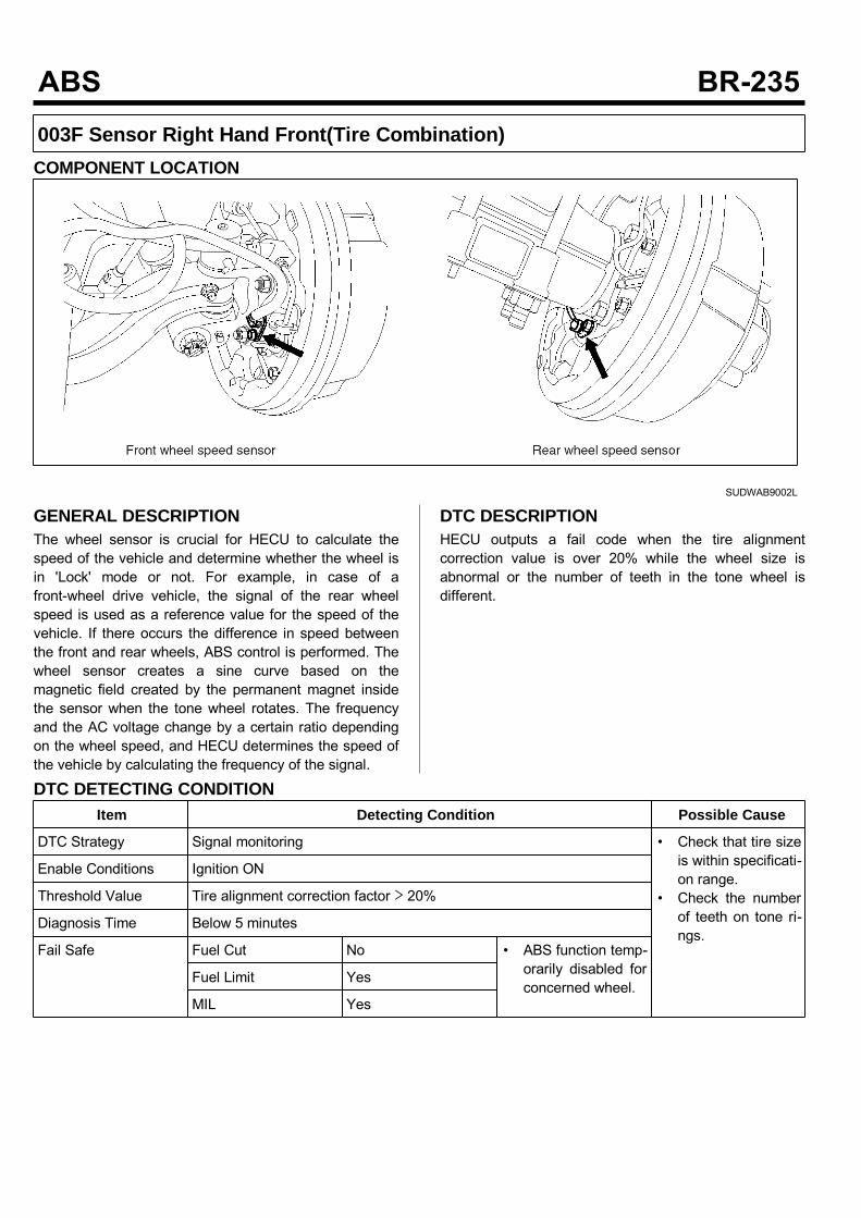
003F Sensor Right Hand Front(Tire Combination)COMPONENT LOCATION
SUDWAB9002L
GENERAL DESCRIPTIONThe wheel sensor is crucial for HECU to calculate thespeed of the vehicle and determine whether the wheel isin 'Lock' mode or not. For example, in case of afront-wheel drive vehicle, the signal of the rear wheelspeed is used as a reference value for the speed of thevehicle. If there occurs the difference in speed betweenthe front and rear wheels, ABS control is performed. Thewheel sensor creates a sine curve based on themagnetic field created by the permanent magnet insidethe sensor when the tone wheel rotates. The frequencyand the AC voltage change by a certain ratio dependingon the wheel speed, and HECU determines the speed ofthe vehicle by calculating the frequency of the signal.
DTC DESCRIPTIONHECU outputs a fail code when the tire alignmentcorrection value is over 20% while the wheel size isabnormal or the number of teeth in the tone wheel isdifferent.
DTC DETECTING CONDITIONItem Detecting Condition Possible Cause
DTC Strategy Signal monitoring • Check that tire sizeis within specificati-on range.
• Check the numberof teeth on tone ri-ngs.
Enable Conditions Ignition ON
Threshold Value Tire alignment correction factor > 20%
Diagnosis Time Below 5 minutes
Fail Safe Fuel Cut No • ABS function temp-orarily disabled forconcerned wheel.
Fuel Limit Yes
MIL Yes
MONITOR SCAN TOOL DATA1. Start the engine.2. Connect the scan tool to the self-diagnosisconnector. Select the service data.
3. Drive the vehicle straight at a constant speed in thenormal road surface.
4. Monitor the data "Wheel speed RHF" parameter onthe scan tool. Specification: Normal if its speed is nearly inaccordance with the speed in the gauge.
5. Is the data measured within specification?
There may be the poor contact of wheel sensorcircuit or a past trouble which did not erase thememory of HECU after having repaired. Totally checkthe connector for looseness, poor contact, bent,corrosion, contamination, deformation, or damage. Repair or replace it if necessary and go to"Verification of Vehicle Repair” procedure.
Go to “Terminal & Connector Inspection”procedure.
TERMINAL & CONNECTOR INSPECTION1. Many malfunctions in the electrical system arecaused by poor harness, and terminals.Faults can also be caused by interference from otherelectrical systems, and mechanical or chemicaldamage.
2. Thoroughly check connectors for looseness, poorconnection, bent, corrosion, contamination,deterioration, or damage.
3. Has a problem been found?
Repair as necessary and then go to “Verification ofVehicle Repair” procedure.
Go to “Signal Circuit Inspection” procedure.
COMPONENT INSPECTIONCheck Tire Size1. Turn the ignition OFF.2. Check tires and wheel size.3. Are tires installed within specification?
Go to next procedure.
Replace tires and wheel size in specification andgo to "Verification of Vehicle Repair" procedure.
Check the Number of Teeth on Tone Rings1. Turn the ignition OFF.2. Check the number of teeth on right hand front tonering.
3. Is the number of tone wheel correct?
Go to "Verification of Vehicle Repair” procedure.
Repair or replace the tone ring and check thecondition of vehicle. If normal, replace with new oneand go to "Verification of Vehicle Repair” procedure.
VERIFICATION OF VEHICLE REPAIRAfter a repair, it is essential to verify that the fault hasbeen corrected.1. Connect the scan tool and perform the self diagnosis.Check diagnostic trouble codes.
2. Clear the diagnostic trouble codes (DTCs) stored inthe ECM by using the scan tool.
3. Drive the vehicle under conditions noted in failurerecords.
4. Check that there are any DTCs by performing selfdiagnosis with the scan tool.
5. Did the DTC return?
Go to the applicable DTC procedure.
System OK
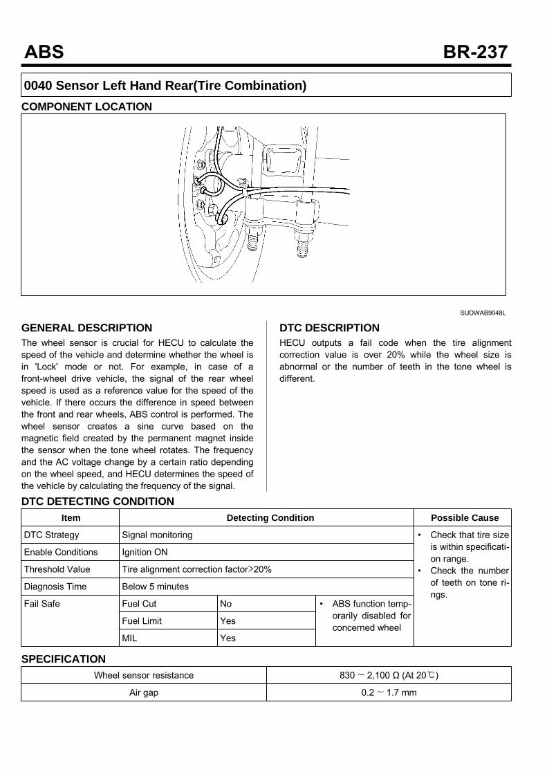
0040 Sensor Left Hand Rear(Tire Combination)COMPONENT LOCATION
SUDWAB9048L
GENERAL DESCRIPTIONThe wheel sensor is crucial for HECU to calculate thespeed of the vehicle and determine whether the wheel isin 'Lock' mode or not. For example, in case of afront-wheel drive vehicle, the signal of the rear wheelspeed is used as a reference value for the speed of thevehicle. If there occurs the difference in speed betweenthe front and rear wheels, ABS control is performed. Thewheel sensor creates a sine curve based on themagnetic field created by the permanent magnet insidethe sensor when the tone wheel rotates. The frequencyand the AC voltage change by a certain ratio dependingon the wheel speed, and HECU determines the speed ofthe vehicle by calculating the frequency of the signal.
DTC DESCRIPTIONHECU outputs a fail code when the tire alignmentcorrection value is over 20% while the wheel size isabnormal or the number of teeth in the tone wheel isdifferent.
DTC DETECTING CONDITIONItem Detecting Condition Possible Cause
DTC Strategy Signal monitoring • Check that tire sizeis within specificati-on range.
• Check the numberof teeth on tone ri-ngs.
Enable Conditions Ignition ON
Threshold Value Tire alignment correction factor>20%
Diagnosis Time Below 5 minutes
Fail Safe Fuel Cut No • ABS function temp-orarily disabled forconcerned wheel
Fuel Limit Yes
MIL Yes
SPECIFICATIONWheel sensor resistance 830 ~ 2,100 Ω (At 20)
Air gap 0.2 ~ 1.7 mm
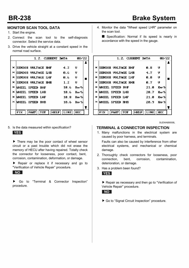
MONITOR SCAN TOOL DATA1. Start the engine.2. Connect the scan tool to the self-diagnosisconnector. Select the service data.
3. Drive the vehicle straight at a constant speed in thenormal road surface.
4. Monitor the data "Wheel speed LHR" parameter onthe scan tool. Specification: Normal if its speed is nearly inaccordance with the speed in the gauge.
SUDWAB9008L
5. Is the data measured within specification?
There may be the poor contact of wheel sensorcircuit or a past trouble which did not erase thememory of HECU after having repaired. Totally checkthe connector for looseness, poor contact, bent,corrosion, contamination, deformation, or damage. Repair or replace it if necessary and go to"Verification of Vehicle Repair” procedure.
Go to “Terminal & Connector Inspection”procedure.
TERMINAL & CONNECTOR INSPECTION1. Many malfunctions in the electrical system arecaused by poor harness, and terminals.Faults can also be caused by interference from otherelectrical systems, and mechanical or chemicaldamage.
2. Thoroughly check connectors for looseness, poorconnection, bent, corrosion, contamination,deterioration, or damage.
3. Has a problem been found?
Repair as necessary and then go to “Verification ofVehicle Repair” procedure.
Go to “Signal Circuit Inspection” procedure.
COMPONENT INSPECTION1. Turn the ignition OFF.2. Check tires and wheel size.3. Are tires installed within specification?
Go to next procedure.
Replace tires and wheel size in specification andgo to "Verification of Vehicle Repair" procedure.
Check the Number of Teeth on Tone Rings1. Turn the ignition OFF.2. Check the number of teeth on left hand rear tonering.
3. Is the number of tone wheel correct?
Go to "Verification of Vehicle Repair” procedure.
Repair or replace the tone ring and check thecondition of vehicle. If normal, replace with new oneand go to "Verification of Vehicle Repair” procedure.
VERIFICATION OF VEHICLE REPAIRAfter a repair, it is essential to verify that the fault hasbeen corrected.1. Connect the scan tool and perform the selfdiagnosis.Check diagnostic trouble codes.
2. Clear the diagnostic trouble codes (DTCs) stored inthe ECM by using the scan tool.
3. Drive the vehicle under conditions noted in failurerecords.
4. Check that there are any DTCs by performing selfdiagnosis with the scan tool.
5. Did the DTC return?
Go to the applicable DTC procedure.
System OK
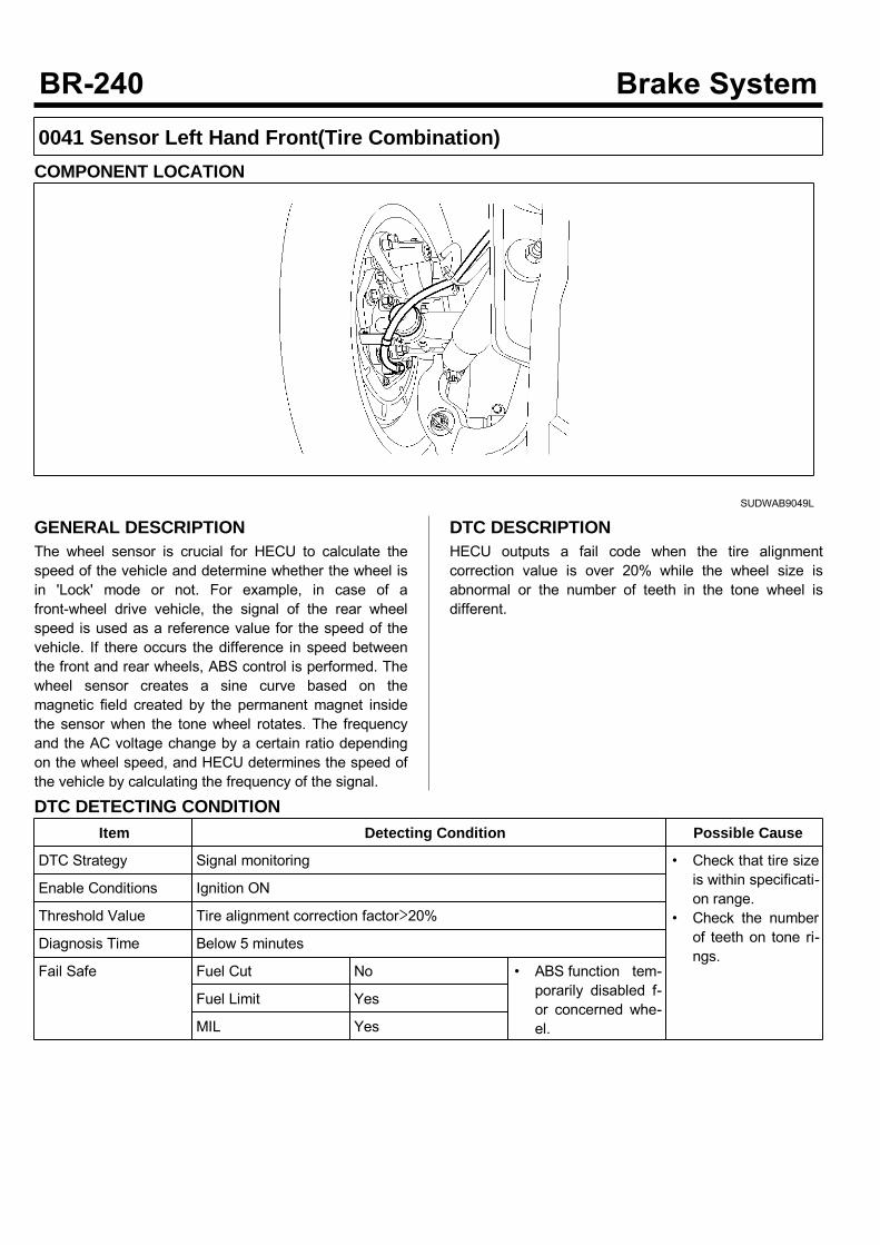
0041 Sensor Left Hand Front(Tire Combination)COMPONENT LOCATION
SUDWAB9049L
GENERAL DESCRIPTIONThe wheel sensor is crucial for HECU to calculate thespeed of the vehicle and determine whether the wheel isin 'Lock' mode or not. For example, in case of afront-wheel drive vehicle, the signal of the rear wheelspeed is used as a reference value for the speed of thevehicle. If there occurs the difference in speed betweenthe front and rear wheels, ABS control is performed. Thewheel sensor creates a sine curve based on themagnetic field created by the permanent magnet insidethe sensor when the tone wheel rotates. The frequencyand the AC voltage change by a certain ratio dependingon the wheel speed, and HECU determines the speed ofthe vehicle by calculating the frequency of the signal.
DTC DESCRIPTIONHECU outputs a fail code when the tire alignmentcorrection value is over 20% while the wheel size isabnormal or the number of teeth in the tone wheel isdifferent.
DTC DETECTING CONDITIONItem Detecting Condition Possible Cause
DTC Strategy Signal monitoring • Check that tire sizeis within specificati-on range.
• Check the numberof teeth on tone ri-ngs.
Enable Conditions Ignition ON
Threshold Value Tire alignment correction factor>20%
Diagnosis Time Below 5 minutes
Fail Safe Fuel Cut No • ABS function tem-porarily disabled f-or concerned whe-el.
Fuel Limit Yes
MIL Yes

MONITOR SCAN TOOL DATA1. Start the engine.2. Connect the scan tool to the self-diagnosisconnector. Select the service data.
3. Drive the vehicle straight at a constant speed in thenormal road surface.
4. Monitor the data "Wheel speed LHF" parameter onthe scan tool. Specification: Normal if its speed is nearly inaccordance with the speed in the gauge.
SUDWAB9008L
5. Is the data measured within specification?
There may be the poor contact of wheel sensorcircuit or a past trouble which did not erase thememory of HECU after having repaired. Totally checkthe connector for looseness, poor contact, bent,corrosion, contamination, deformation, or damage. Repair or replace it if necessary and go to"Verification of Vehicle Repair” procedure.
Go to “Terminal & Connector Inspection”procedure.
TERMINAL & CONNECTOR INSPECTION1. Many malfunctions in the electrical system arecaused by poor harness, and terminals.Faults can also be caused by interference from otherelectrical systems, and mechanical or chemicaldamage.
2. Thoroughly check connectors for looseness, poorconnection, bent, corrosion, contamination,deterioration, or damage.
3. Has a problem been found?
Repair as necessary and then go to “Verification ofVehicle Repair” procedure.
Go to “Signal Circuit Inspection” procedure.
COMPONENT INSPECTION1. Turn the ignition OFF.2. Check tires and wheel size.3. Are tires installed within specification?
Go to next procedure.
Replace tires and wheel size in specification andgo to "Verification of Vehicle Repair" procedure.
Check the Number of Teeth on Tone Rings1. Turn the ignition OFF.2. Check the number of teeth on left hand rear tonering.
3. Is the number of tone wheel correct?
Go to "Verification of Vehicle Repair” procedure.
Repair or replace the tone ring and check thecondition of vehicle. If normal, replace with new oneand go to "Verification of Vehicle Repair” procedure.
VERIFICATION OF VEHICLE REPAIRAfter a repair, it is essential to verify that the fault hasbeen corrected.1. Connect the scan tool and perform the self diagnosis.Check diagnostic trouble codes.
2. Clear the diagnostic trouble codes (DTCs) stored inthe ECM by using the scan tool.
3. Drive the vehicle under conditions noted in failurerecords.
4. Check that there are any DTCs by performing selfdiagnosis with the scan tool.
5. Did the DTC return?
Go to the applicable DTC procedure.
System OK
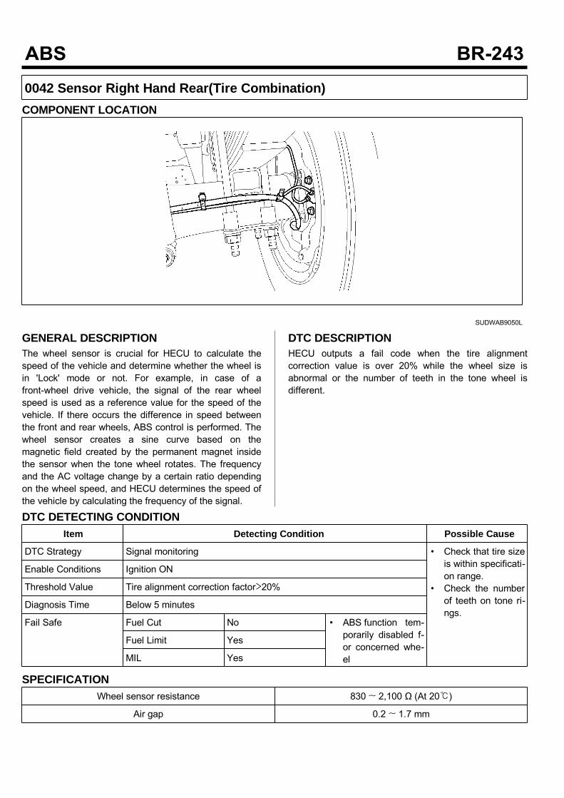
0042 Sensor Right Hand Rear(Tire Combination)COMPONENT LOCATION
SUDWAB9050L
GENERAL DESCRIPTIONThe wheel sensor is crucial for HECU to calculate thespeed of the vehicle and determine whether the wheel isin 'Lock' mode or not. For example, in case of afront-wheel drive vehicle, the signal of the rear wheelspeed is used as a reference value for the speed of thevehicle. If there occurs the difference in speed betweenthe front and rear wheels, ABS control is performed. Thewheel sensor creates a sine curve based on themagnetic field created by the permanent magnet insidethe sensor when the tone wheel rotates. The frequencyand the AC voltage change by a certain ratio dependingon the wheel speed, and HECU determines the speed ofthe vehicle by calculating the frequency of the signal.
DTC DESCRIPTIONHECU outputs a fail code when the tire alignmentcorrection value is over 20% while the wheel size isabnormal or the number of teeth in the tone wheel isdifferent.
DTC DETECTING CONDITIONItem Detecting Condition Possible Cause
DTC Strategy Signal monitoring • Check that tire sizeis within specificati-on range.
• Check the numberof teeth on tone ri-ngs.
Enable Conditions Ignition ON
Threshold Value Tire alignment correction factor>20%
Diagnosis Time Below 5 minutes
Fail Safe Fuel Cut No • ABS function tem-porarily disabled f-or concerned whe-el
Fuel Limit Yes
MIL Yes
SPECIFICATIONWheel sensor resistance 830 ~ 2,100 Ω (At 20)
Air gap 0.2 ~ 1.7 mm
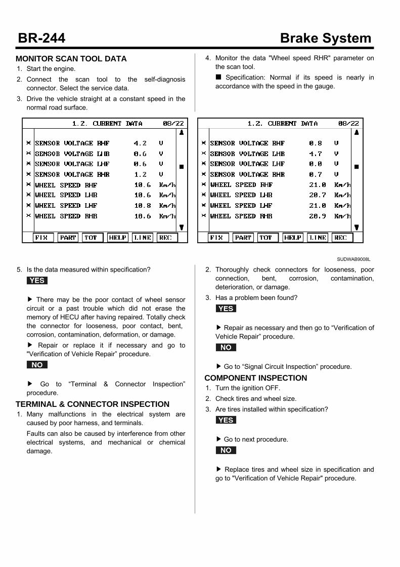
MONITOR SCAN TOOL DATA1. Start the engine.2. Connect the scan tool to the self-diagnosisconnector. Select the service data.
3. Drive the vehicle straight at a constant speed in thenormal road surface.
4. Monitor the data "Wheel speed RHR" parameter onthe scan tool. Specification: Normal if its speed is nearly inaccordance with the speed in the gauge.
SUDWAB9008L
5. Is the data measured within specification?
There may be the poor contact of wheel sensorcircuit or a past trouble which did not erase thememory of HECU after having repaired. Totally checkthe connector for looseness, poor contact, bent,corrosion, contamination, deformation, or damage. Repair or replace it if necessary and go to"Verification of Vehicle Repair” procedure.
Go to “Terminal & Connector Inspection”procedure.
TERMINAL & CONNECTOR INSPECTION1. Many malfunctions in the electrical system arecaused by poor harness, and terminals.Faults can also be caused by interference from otherelectrical systems, and mechanical or chemicaldamage.
2. Thoroughly check connectors for looseness, poorconnection, bent, corrosion, contamination,deterioration, or damage.
3. Has a problem been found?
Repair as necessary and then go to “Verification ofVehicle Repair” procedure.
Go to “Signal Circuit Inspection” procedure.
COMPONENT INSPECTION1. Turn the ignition OFF.2. Check tires and wheel size.3. Are tires installed within specification?
Go to next procedure.
Replace tires and wheel size in specification andgo to "Verification of Vehicle Repair" procedure.
Check the Number of Teeth on Tone Rings1. Turn the ignition OFF.2. Check the number of teeth on right hand rear tonering.
3. Is the number of tone wheel correct?
Go to "Verification of Vehicle Repair” procedure.
Repair or replace the tone ring and check thecondition of vehicle. If normal, replace with new oneand go to "Verification of Vehicle Repair” procedure.
VERIFICATION OF VEHICLE REPAIRAfter a repair, it is essential to verify that the fault hasbeen corrected.1. Connect the scan tool and perform the self diagnosis.Check diagnostic trouble codes.
2. Clear the diagnostic trouble codes (DTCs) stored inthe ECM by using the scan tool.
3. Drive the vehicle under conditions noted in failurerecords.
4. Check that there are any DTCs by performing selfdiagnosis with the scan tool.
5. Did the DTC return?
Go to the applicable DTC procedure.
System OK
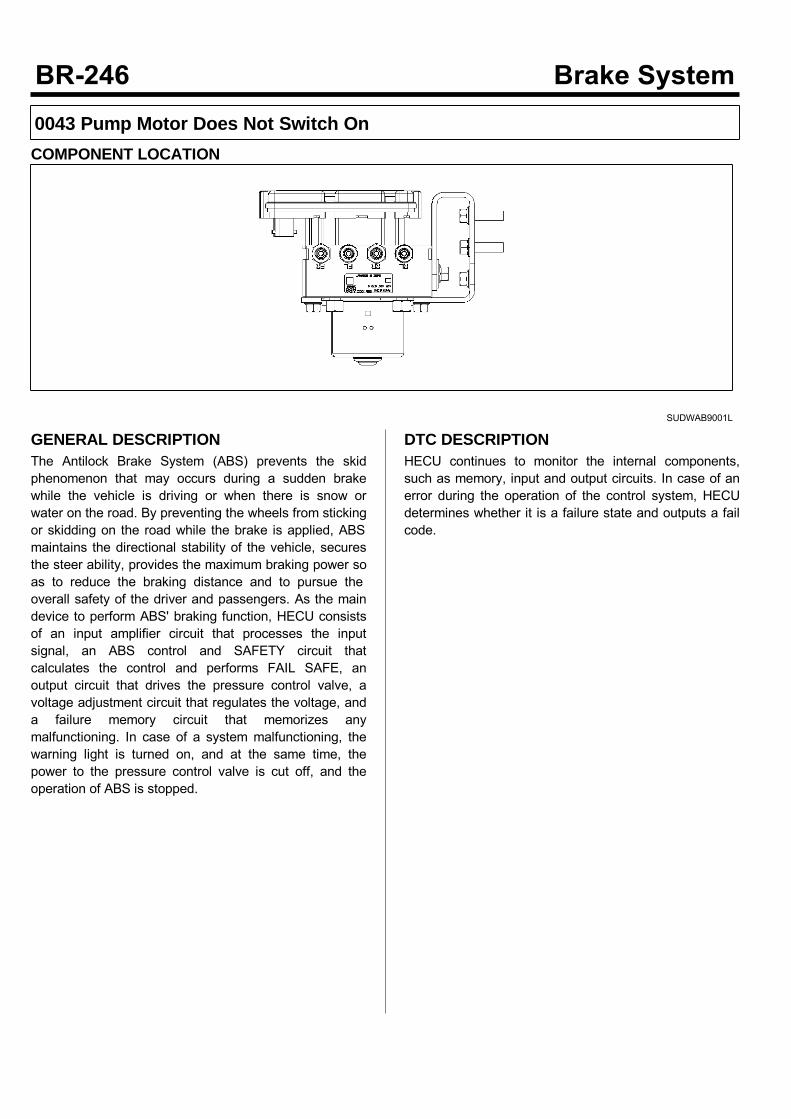
0043 Pump Motor Does Not Switch OnCOMPONENT LOCATION
SUDWAB9001L
GENERAL DESCRIPTIONThe Antilock Brake System (ABS) prevents the skidphenomenon that may occurs during a sudden brakewhile the vehicle is driving or when there is snow orwater on the road. By preventing the wheels from stickingor skidding on the road while the brake is applied, ABSmaintains the directional stability of the vehicle, securesthe steer ability, provides the maximum braking power soas to reduce the braking distance and to pursue theoverall safety of the driver and passengers. As the maindevice to perform ABS' braking function, HECU consistsof an input amplifier circuit that processes the inputsignal, an ABS control and SAFETY circuit thatcalculates the control and performs FAIL SAFE, anoutput circuit that drives the pressure control valve, avoltage adjustment circuit that regulates the voltage, anda failure memory circuit that memorizes anymalfunctioning. In case of a system malfunctioning, thewarning light is turned on, and at the same time, thepower to the pressure control valve is cut off, and theoperation of ABS is stopped.
DTC DESCRIPTIONHECU continues to monitor the internal components,such as memory, input and output circuits. In case of anerror during the operation of the control system, HECUdetermines whether it is a failure state and outputs a failcode.

DTC DETECTING CONDITIONItem Detecting Condition Possible Cause
DTC Strategy Signal monitoring • Replace ECU.
Enable Conditions Ignition ON
Threshold Value When the pump motor in HECU does not work
Diagnosis Time Below 1,000 ms
Fail Safe Fuel Cut No • ABS disabled
Fuel Limit Yes
MIL Yes
MONITOR SCAN TOOL DATA1. Connect the scan tool to the self-diagnosisconnector.
2. Turn the ignition ON.3. Select the data "Actuation test"
4. Check the pump motor for operation when activatingthe actuator. Specification: Normal if the activating sound isheard.
SUDWAB9040L
5. Does the valve activate normally?
There may be a transient trouble due to defectivevalve or a past trouble which did not erase thememory of HECU after having repair. And go to "Verification of Vehicle Repair”procedure.
Go to "Component Inspection" procedure.
TERMINAL & CONNECTOR INSPECTION1. Many malfunctions in the electrical system arecaused by poor harness, and terminals.Faults can also be caused by interference from otherelectrical systems, and mechanical or chemicaldamage.
2. Thoroughly check connectors for looseness, poorconnection, bent, corrosion, contamination,deterioration, or damage.
3. Has a problem been found?
Repair as necessary and then go to “Verification ofVehicle Repair” procedure.

Go to “Signal Circuit Inspection” procedure.
COMPONENT INSPECTION1. Start the engine.2. Drive the vehicle with approx. 15km/h or higher.3. Turn the ignition ON. Leave the engine OFF.4. Connect the scan tool and check the diagnostictrouble codes by using self-diagnosis.
5. Using the scan tool erase the diagnostic troublecodes stored in the HECU.
6. Check that there are any diagnostic trouble codes byusing self-diagnosis with the scan tool.
7. Are any diagnostic trouble codes (DTCs) detected?
Check that the DTCs have disappeared afterreplacing with a known-good HECU. If the problemhas solved, we may guess the HECU is problem.Replace the HECU and go to “Verification of VehicleRepair” procedure.
There may be a defective valve component or atransient trouble due to a past trouble which did noterase the memory of HECU after having repair. Andgo to "Verification of Vehicle Repair” procedure.
VERIFICATION OF VEHICLE REPAIRAfter a repair, it is essential to verify that the fault hasbeen corrected.1. Connect the scan tool and perform the self diagnosis.Check diagnostic trouble codes.
2. Clear the diagnostic trouble codes (DTCs) stored inthe ECM by using the scan tool.
3. Drive the vehicle under conditions noted in failurerecords.
4. Check that there are any DTCs by performing selfdiagnosis with the scan tool.
5. Did the DTC return?
Go to the applicable DTC procedure.
System OK

0044 Pump Motor Does Not Switch OffCOMPONENT LOCATION
SUDWAB9001L
GENERAL DESCRIPTIONThe Antilock Brake System (ABS) prevents the skidphenomenon that may occurs during a sudden brakewhile the vehicle is driving or when there is snow orwater on the road. By preventing the wheels from stickingor skidding on the road while the brake is applied, ABSmaintains the directional stability of the vehicle, securesthe steer ability, provides the maximum braking power soas to reduce the braking distance and to pursue theoverall safety of the driver and passengers. As the maindevice to perform ABS' braking function, HECU consistsof an input amplifier circuit that processes the inputsignal, an ABS control and SAFETY circuit thatcalculates the control and performs FAIL SAFE, anoutput circuit that drives the pressure control valve, avoltage adjustment circuit that regulates the voltage, anda failure memory circuit that memorizes anymalfunctioning. In case of a system malfunctioning, thewarning light is turned on, and at the same time, thepower to the pressure control valve is cut off, and theoperation of ABS is stopped.
DTC DESCRIPTIONHECU continues to monitor the internal components,such as memory, input and output circuits. In case of anerror during the operation of the control system, HECUdetermines whether it is a failure state and outputs a failcode.

DTC DETECTING CONDITIONItem Detecting Condition Possible Cause
DTC Strategy Signal monitoring • Replace ECU.
Enable Conditions Ignition ON
Threshold Value When the pump motor in HECU will not stop
Diagnosis Time Below 1,000 ms
Fail Safe Fuel Cut No • ABS disabled
Fuel Limit Yes
MIL Yes
MONITOR SCAN TOOL DATA1. Connect the scan tool to the self-diagnosisconnector.
2. Turn the ignition ON.3. Select the data "Actuation test".
4. Check the pump motor for operation when activatingthe actuator. Specification: Normal if the activating sound isheard.
SUDWAB9041L
5. Does the valve activate normally?
There may be a transient trouble due to defectivevalve or a past trouble which did not erase thememory of HECU after having repair. And go to "Verification of Vehicle Repair”procedure.
Go to "Component Inspection" procedure.
TERMINAL & CONNECTOR INSPECTION1. Many malfunctions in the electrical system arecaused by poor harness, and terminals.Faults can also be caused by interference from otherelectrical systems, and mechanical or chemicaldamage.
2. Thoroughly check connectors for looseness, poorconnection, bent, corrosion, contamination,deterioration, or damage.
3. Has a problem been found?
Repair as necessary and then go to “Verification ofVehicle Repair” procedure.
Go to “Signal Circuit Inspection” procedure.
COMPONENT INSPECTION1. Start the engine.2. Drive the vehicle with approx. 15km/h or higher.3. Turn the ignition ON. Leave the engine OFF.4. Connect the scan tool and check the diagnostictrouble codes by using self-diagnosis.
5. Using the scan tool erase the diagnostic troublecodes stored in the HECU.
6. Check that there are any diagnostic trouble codes byusing self-diagnosis with the scan tool.
7. Are any diagnostic trouble codes (DTCs) detected?
Check that the DTCs have disappeared afterreplacing with a known-good HECU. If the problemhas solved, we may guess the HECU is problem.Replace the HECU and go to “Verification of VehicleRepair” procedure.
There may be a defective valve component or atransient trouble due to a past trouble which did noterase the memory of HECU after having repair. Andgo to "Verification of Vehicle Repair” procedure.
VERIFICATION OF VEHICLE REPAIRAfter a repair, it is essential to verify that the fault hasbeen corrected.1. Connect the scan tool and perform the self diagnosis.Check diagnostic trouble codes.
2. Clear the diagnostic trouble codes (DTCs) stored inthe ECM by using the scan tool.
3. Drive the vehicle under conditions noted in failurerecords.
4. Check that there are any DTCs by performing selfdiagnosis with the scan tool.
5. Did the DTC return?
Go to the applicable DTC procedure.
System OK

0045 Pump Motor Does Not TurnCOMPONENT LOCATION
SUDWAB9001L
GENERAL DESCRIPTIONThe Antilock Brake System (ABS) prevents the skidphenomenon that may occurs during a sudden brakewhile the vehicle is driving or when there is snow orwater on the road. By preventing the wheels from stickingor skidding on the road while the brake is applied, ABSmaintains the directional stability of the vehicle, securesthe steer ability, provides the maximum braking power soas to reduce the braking distance and to pursue theoverall safety of the driver and passengers. As the maindevice to perform ABS' braking function, HECU consistsof an input amplifier circuit that processes the inputsignal, an ABS control and SAFETY circuit thatcalculates the control and performs FAIL SAFE, anoutput circuit that drives the pressure control valve, avoltage adjustment circuit that regulates the voltage, anda failure memory circuit that memorizes anymalfunctioning. In case of a system malfunctioning, thewarning light is turned on, and at the same time, thepower to the pressure control valve is cut off, and theoperation of ABS is stopped.
DTC DESCRIPTIONHECU continues to monitor the internal components,such as memory, input and output circuits. In case of anerror during the operation of the control system, HECUdetermines whether it is a failure state and outputs a failcode.
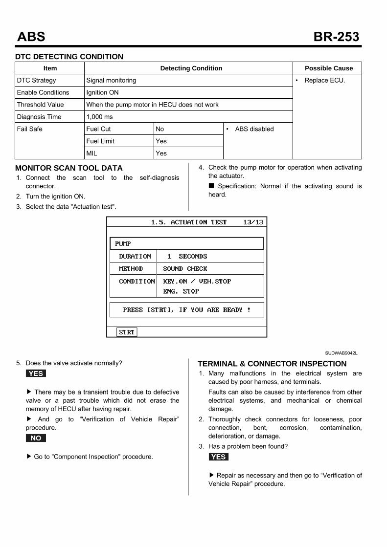
DTC DETECTING CONDITIONItem Detecting Condition Possible Cause
DTC Strategy Signal monitoring • Replace ECU.
Enable Conditions Ignition ON
Threshold Value When the pump motor in HECU does not work
Diagnosis Time 1,000 ms
Fail Safe Fuel Cut No • ABS disabled
Fuel Limit Yes
MIL Yes
MONITOR SCAN TOOL DATA1. Connect the scan tool to the self-diagnosisconnector.
2. Turn the ignition ON.3. Select the data "Actuation test".
4. Check the pump motor for operation when activatingthe actuator. Specification: Normal if the activating sound isheard.
SUDWAB9042L
5. Does the valve activate normally?
There may be a transient trouble due to defectivevalve or a past trouble which did not erase thememory of HECU after having repair. And go to "Verification of Vehicle Repair”procedure.
Go to "Component Inspection" procedure.
TERMINAL & CONNECTOR INSPECTION1. Many malfunctions in the electrical system arecaused by poor harness, and terminals.Faults can also be caused by interference from otherelectrical systems, and mechanical or chemicaldamage.
2. Thoroughly check connectors for looseness, poorconnection, bent, corrosion, contamination,deterioration, or damage.
3. Has a problem been found?
Repair as necessary and then go to “Verification ofVehicle Repair” procedure.

Go to “Signal Circuit Inspection” procedure.
COMPONENT INSPECTION1. Start the engine.2. Drive the vehicle with approx. 15km/h or higher.3. Turn the ignition ON. Leave the engine OFF.4. Connect the scan tool and check the diagnostictrouble codes by using self-diagnosis.
5. Using the scan tool erase the diagnostic troublecodes stored in the HECU.
6. Check that there are any diagnostic trouble codes byusing self-diagnosis with the scan tool.
7. Are any diagnostic trouble codes (DTCs) detected?
Check that the DTCs have disappeared afterreplacing with a known-good HECU. If the problemhas solved, we may guess the HECU is problem.Replace the HECU and go to “Verification of VehicleRepair” procedure.
There may be a defective valve component or atransient trouble due to a past trouble which did noterase the memory of HECU after having repair. Andgo to "Verification of Vehicle Repair” procedure.
VERIFICATION OF VEHICLE REPAIRAfter a repair, it is essential to verify that the fault hasbeen corrected.1. Connect the scan tool and perform the self diagnosis.Check diagnostic trouble codes.
2. Clear the diagnostic trouble codes (DTCs) stored inthe ECM by using the scan tool.
3. Drive the vehicle under conditions noted in failurerecords.
4. Check that there are any DTCs by performing selfdiagnosis with the scan tool.
5. Did the DTC return?
Go to the applicable DTC procedure.
System OK
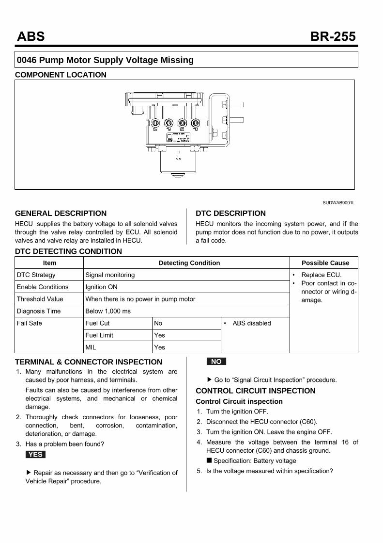
0046 Pump Motor Supply Voltage MissingCOMPONENT LOCATION
SUDWAB9001L
GENERAL DESCRIPTIONHECU supplies the battery voltage to all solenoid valvesthrough the valve relay controlled by ECU. All solenoidvalves and valve relay are installed in HECU.
DTC DESCRIPTIONHECU monitors the incoming system power, and if thepump motor does not function due to no power, it outputsa fail code.
DTC DETECTING CONDITIONItem Detecting Condition Possible Cause
DTC Strategy Signal monitoring • Replace ECU.• Poor contact in co-nnector or wiring d-amage.
Enable Conditions Ignition ON
Threshold Value When there is no power in pump motor
Diagnosis Time Below 1,000 ms
Fail Safe Fuel Cut No • ABS disabled
Fuel Limit Yes
MIL Yes
TERMINAL & CONNECTOR INSPECTION1. Many malfunctions in the electrical system arecaused by poor harness, and terminals.Faults can also be caused by interference from otherelectrical systems, and mechanical or chemicaldamage.
2. Thoroughly check connectors for looseness, poorconnection, bent, corrosion, contamination,deterioration, or damage.
3. Has a problem been found?
Repair as necessary and then go to “Verification ofVehicle Repair” procedure.
Go to “Signal Circuit Inspection” procedure.
CONTROL CIRCUIT INSPECTIONControl Circuit inspection1. Turn the ignition OFF.2. Disconnect the HECU connector (C60).3. Turn the ignition ON. Leave the engine OFF.4. Measure the voltage between the terminal 16 ofHECU connector (C60) and chassis ground. Specification: Battery voltage
5. Is the voltage measured within specification?
Go to "Ground Circuit Inspection" procedure.
Check the fuse 30A. If it is burnt, replace it. Whenthe fuse is normal, check open circuit betweenterminal (+) of battery and terminal 16 of HECUconnector (C60) and short to ground. Repair if thereis any problem and go to “Verification of VehicleRepair” procedure.
GROUND CIRCUIT INSPECTION1. Turn the ignition OFF.2. Disconnect the HECU connector (C60).3. Measure the resistance between the terminals 18, 19of HECU harness connector (C60) and chassisground. Specification: Continuity
4. Is the resistance measured within specification?
Go to “Component Inspection” procedure.
Check open or poor contact between the solenoidvalve ground of HECU harness connector andchassis ground. And go to "Verification of VehicleRepair” procedure.
COMPONENT INSPECTION1. Start the engine.2. Drive the vehicle with approx. 15km/h or higher.3. Turn the ignition ON. Leave the engine OFF.4. Connect the scan tool and check the diagnostictrouble codes by using self-diagnosis.
5. Using the scan tool erase the diagnostic troublecodes stored in the HECU.
6. Check that there are any diagnostic trouble codes byusing self-diagnosis with the scan tool.
7. Are any diagnostic trouble codes (DTCs) detected?
Check that the DTCs have disappeared afterreplacing with a known-good HECU. If the problemhas solved, we may guess the HECU is problem.Replace the HECU and go to “Verification of VehicleRepair” procedure.
There may be a defective valve component or atransient trouble due to a past trouble which did noterase the memory of HECU after having repair. Andgo to "Verification of Vehicle Repair” procedure.
VERIFICATION OF VEHICLE REPAIRAfter a repair, it is essential to verify that the fault hasbeen corrected.1. Connect the scan tool and perform the self diagnosis.Check diagnostic trouble codes.
2. Clear the diagnostic trouble codes (DTCs) stored inthe ECM by using the scan tool.
3. Drive the vehicle under conditions noted in failurerecords.
4. Check that there are any DTCs by performing selfdiagnosis with the scan tool.
5. Did the DTC return?
Go to the applicable DTC procedure.
System OK
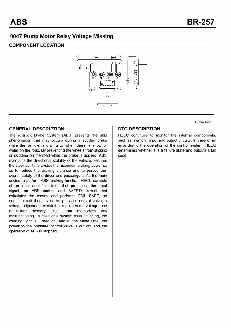
0047 Pump Motor Relay Voltage MissingCOMPONENT LOCATION
SUDWAB9001L
GENERAL DESCRIPTIONThe Antilock Brake System (ABS) prevents the skidphenomenon that may occurs during a sudden brakewhile the vehicle is driving or when there is snow orwater on the road. By preventing the wheels from stickingor skidding on the road while the brake is applied, ABSmaintains the directional stability of the vehicle, securesthe steer ability, provides the maximum braking power soas to reduce the braking distance and to pursue theoverall safety of the driver and passengers. As the maindevice to perform ABS' braking function, HECU consistsof an input amplifier circuit that processes the inputsignal, an ABS control and SAFETY circuit thatcalculates the control and performs FAIL SAFE, anoutput circuit that drives the pressure control valve, avoltage adjustment circuit that regulates the voltage, anda failure memory circuit that memorizes anymalfunctioning. In case of a system malfunctioning, thewarning light is turned on, and at the same time, thepower to the pressure control valve is cut off, and theoperation of ABS is stopped.
DTC DESCRIPTIONHECU continues to monitor the internal components,such as memory, input and output circuits. In case of anerror during the operation of the control system, HECUdetermines whether it is a failure state and outputs a failcode.
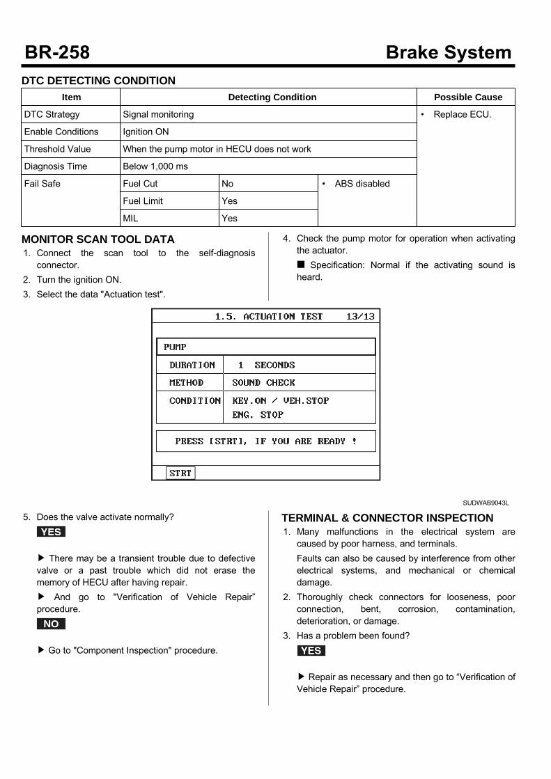
DTC DETECTING CONDITIONItem Detecting Condition Possible Cause
DTC Strategy Signal monitoring • Replace ECU.
Enable Conditions Ignition ON
Threshold Value When the pump motor in HECU does not work
Diagnosis Time Below 1,000 ms
Fail Safe Fuel Cut No • ABS disabled
Fuel Limit Yes
MIL Yes
MONITOR SCAN TOOL DATA1. Connect the scan tool to the self-diagnosisconnector.
2. Turn the ignition ON.3. Select the data "Actuation test".
4. Check the pump motor for operation when activatingthe actuator. Specification: Normal if the activating sound isheard.
SUDWAB9043L
5. Does the valve activate normally?
There may be a transient trouble due to defectivevalve or a past trouble which did not erase thememory of HECU after having repair. And go to "Verification of Vehicle Repair”procedure.
Go to "Component Inspection" procedure.
TERMINAL & CONNECTOR INSPECTION1. Many malfunctions in the electrical system arecaused by poor harness, and terminals.Faults can also be caused by interference from otherelectrical systems, and mechanical or chemicaldamage.
2. Thoroughly check connectors for looseness, poorconnection, bent, corrosion, contamination,deterioration, or damage.
3. Has a problem been found?
Repair as necessary and then go to “Verification ofVehicle Repair” procedure.

Go to “Signal Circuit Inspection” procedure.
COMPONENT INSPECTION1. Start the engine.2. Drive the vehicle with approx. 15km/h or higher.3. Turn the ignition ON. Leave the engine OFF.4. Connect the scan tool and check the diagnostictrouble codes by using self-diagnosis.
5. Using the scan tool erase the diagnostic troublecodes stored in the HECU.
6. Check that there are any diagnostic trouble codes byusing self-diagnosis with the scan tool.
7. Are any diagnostic trouble codes (DTCs) detected?
Check that the DTCs have disappeared afterreplacing with a known-good HECU. If the problemhas solved, we may guess the HECU is problem.Replace the HECU and go to “Verification of VehicleRepair” procedure.
There may be a defective valve component or atransient trouble due to a past trouble which did noterase the memory of HECU after having repair. Andgo to "Verification of Vehicle Repair” procedure.
VERIFICATION OF VEHICLE REPAIRAfter a repair, it is essential to verify that the fault hasbeen corrected.1. Connect the scan tool and perform the self diagnosis.Check diagnostic trouble codes.
2. Clear the diagnostic trouble codes (DTCs) stored inthe ECM by using the scan tool.
3. Drive the vehicle under conditions noted in failurerecords.
4. Check that there are any DTCs by performing selfdiagnosis with the scan tool.
5. Did the DTC return?
Go to the applicable DTC procedure.
System OK
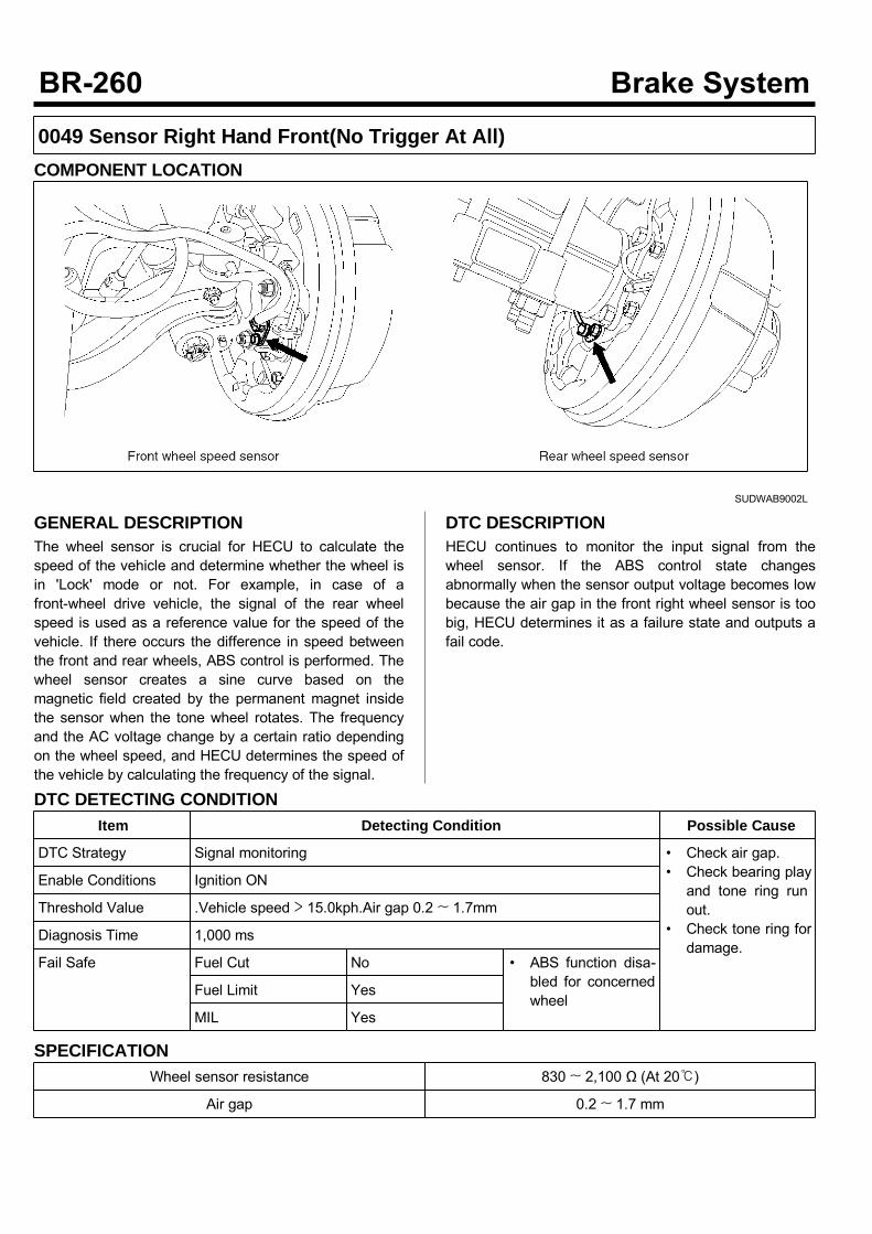
0049 Sensor Right Hand Front(No Trigger At All)COMPONENT LOCATION
SUDWAB9002L
GENERAL DESCRIPTIONThe wheel sensor is crucial for HECU to calculate thespeed of the vehicle and determine whether the wheel isin 'Lock' mode or not. For example, in case of afront-wheel drive vehicle, the signal of the rear wheelspeed is used as a reference value for the speed of thevehicle. If there occurs the difference in speed betweenthe front and rear wheels, ABS control is performed. Thewheel sensor creates a sine curve based on themagnetic field created by the permanent magnet insidethe sensor when the tone wheel rotates. The frequencyand the AC voltage change by a certain ratio dependingon the wheel speed, and HECU determines the speed ofthe vehicle by calculating the frequency of the signal.
DTC DESCRIPTIONHECU continues to monitor the input signal from thewheel sensor. If the ABS control state changesabnormally when the sensor output voltage becomes lowbecause the air gap in the front right wheel sensor is toobig, HECU determines it as a failure state and outputs afail code.
DTC DETECTING CONDITIONItem Detecting Condition Possible Cause
DTC Strategy Signal monitoring • Check air gap.• Check bearing playand tone ring runout.
• Check tone ring fordamage.
Enable Conditions Ignition ON
Threshold Value .Vehicle speed > 15.0kph.Air gap 0.2 ~ 1.7mm
Diagnosis Time 1,000 ms
Fail Safe Fuel Cut No • ABS function disa-bled for concernedwheel
Fuel Limit Yes
MIL Yes
SPECIFICATIONWheel sensor resistance 830 ~ 2,100 Ω (At 20)
Air gap 0.2 ~ 1.7 mm
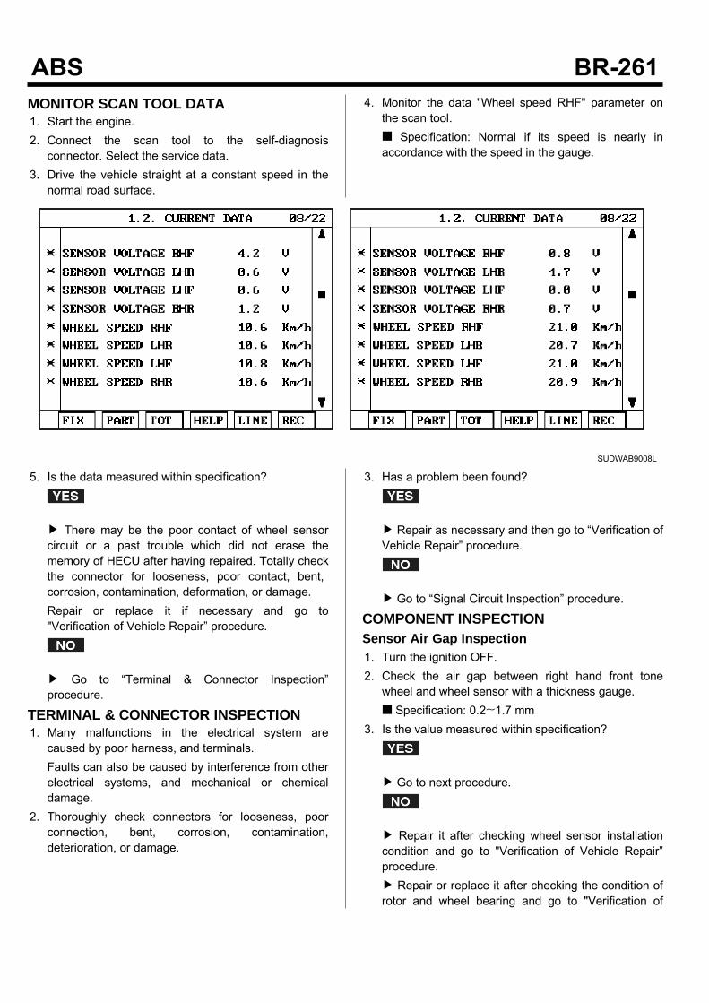
MONITOR SCAN TOOL DATA1. Start the engine.2. Connect the scan tool to the self-diagnosisconnector. Select the service data.
3. Drive the vehicle straight at a constant speed in thenormal road surface.
4. Monitor the data "Wheel speed RHF" parameter onthe scan tool. Specification: Normal if its speed is nearly inaccordance with the speed in the gauge.
SUDWAB9008L
5. Is the data measured within specification?
There may be the poor contact of wheel sensorcircuit or a past trouble which did not erase thememory of HECU after having repaired. Totally checkthe connector for looseness, poor contact, bent,corrosion, contamination, deformation, or damage.Repair or replace it if necessary and go to"Verification of Vehicle Repair” procedure.
Go to “Terminal & Connector Inspection”procedure.
TERMINAL & CONNECTOR INSPECTION1. Many malfunctions in the electrical system arecaused by poor harness, and terminals.Faults can also be caused by interference from otherelectrical systems, and mechanical or chemicaldamage.
2. Thoroughly check connectors for looseness, poorconnection, bent, corrosion, contamination,deterioration, or damage.
3. Has a problem been found?
Repair as necessary and then go to “Verification ofVehicle Repair” procedure.
Go to “Signal Circuit Inspection” procedure.
COMPONENT INSPECTIONSensor Air Gap Inspection1. Turn the ignition OFF.2. Check the air gap between right hand front tonewheel and wheel sensor with a thickness gauge. Specification: 0.2~1.7 mm
3. Is the value measured within specification?
Go to next procedure.
Repair it after checking wheel sensor installationcondition and go to "Verification of Vehicle Repair”procedure. Repair or replace it after checking the condition ofrotor and wheel bearing and go to "Verification of
Vehicle Repair” procedure. Adjust it after checking the air gap between wheelsensor and rotor and go to "Verification of VehicleRepair” procedure.
Right Hand Front Wheel Sensor Inspection1. Turn the ignition OFF.2. Disconnect the right hand front when sensorconnector.
3. Measure the resistance between positive (+) andnegative (-) of the right hand front wheel sensor(C30). Specification: 830 ~ 2,100 Ω (At 20)
4. Is the resistance measured within specification?
After checking the HECU for contamination ordamage, install a known-good HECU and check itgood or not. Replace the HECU if the vehicle is normalcondition and go to "Verification of Vehicle Repair”procedure.
Replace the sensor if the vehicle is normal aftertemporarily installing a known-good sensor and go to"Verification of Vehicle Repair” procedure.
VERIFICATION OF VEHICLE REPAIRAfter a repair, it is essential to verify that the fault hasbeen corrected.1. Connect the scan tool and perform the self diagnosis.Check diagnostic trouble codes.
2. Clear the diagnostic trouble codes (DTCs) stored inthe ECM by using the scan tool.
3. Drive the vehicle under conditions noted in failurerecords.
4. Check that there are any DTCs by performing selfdiagnosis with the scan tool.
5. Did the DTC return?
Go to the applicable DTC procedure.
System OK

004A Sensor Left Hand Rear(No Trigger At All)COMPONENT LOCATION
SUDWAB9048L
GENERAL DESCRIPTIONThe wheel sensor is crucial for HECU to calculate thespeed of the vehicle and determine whether the wheel isin 'Lock' mode or not. For example, in case of afront-wheel drive vehicle, the signal of the rear wheelspeed is used as a reference value for the speed of thevehicle. If there occurs the difference in speed betweenthe front and rear wheels, ABS control is performed. Thewheel sensor creates a sine curve based on themagnetic field created by the permanent magnet insidethe sensor when the tone wheel rotates. The frequencyand the AC voltage change by a certain ratio dependingon the wheel speed, and HECU determines the speed ofthe vehicle by calculating the frequency of the signal.
DTC DESCRIPTIONHECU continues to monitor the input signal from thewheel sensor. If the ABS control state changesabnormally when the sensor output voltage becomes lowbecause the air gap in the rear left wheel sensor is toobig, HECU determines it as a failure state and outputs afail code.
DTC DETECTING CONDITIONItem Detecting Condition Possible Cause
DTC Strategy Signal monitoring • Check air gap.• Check bearing playand tone ring runout.
• Check tone ring fordamage.
Enable Conditions Ignition ON
Threshold Value .Vehicle speed > 15.0 kph.Air gap 0.2 ~ 1.7 mm
Diagnosis Time Below 1,000 ms
Fail Safe Fuel Cut No • ABS function disa-bled for concernedwheel
Fuel Limit Yes
MIL Yes
SPECIFICATIONWheel sensor resistance 830 ~ 2,100 Ω (At 20)
Air gap 0.2 ~ 1.7 mm

MONITOR SCAN TOOL DATA1. Start the engine.2. Connect the scan tool to the self-diagnosisconnector. Select the service data.
3. Drive the vehicle straight at a constant speed in thenormal road surface.
4. Monitor the data "Wheel speed LHR" parameter onthe scan tool. Specification: Normal if its speed is nearly inaccordance with the speed in the gauge.
SUDWAB9008L
5. Is the data measured within specification?
There may be the poor contact of wheel sensorcircuit or a past trouble which did not erase thememory of HECU after having repaired. Totally checkthe connector for looseness, poor contact, bent,corrosion, contamination, deformation, or damage. Repair or replace it if necessary and go to"Verification of Vehicle Repair” procedure.
Go to “Terminal & Connector Inspection”procedure.
TERMINAL & CONNECTOR INSPECTION1. Many malfunctions in the electrical system arecaused by poor harness, and terminals.Faults can also be caused by interference from otherelectrical systems, and mechanical or chemicaldamage.
2. Thoroughly check connectors for looseness, poorconnection, bent, corrosion, contamination,deterioration, or damage.
3. Has a problem been found?
Repair as necessary and then go to “Verification ofVehicle Repair” procedure.
Go to “Signal Circuit Inspection” procedure.
COMPONENT INSPECTIONSensor Air Gap Inspection1. Turn the ignition OFF.2. Check the air gap between left hand rear tone wheeland wheel sensor with a thickness gauge. Specification: 0.2~1.7 mm
3. Is the value measured within specification?
Go to next procedure.
Repair it after checking wheel sensor installationcondition and go to "Verification of Vehicle Repair”procedure. Repair or replace it after checking the condition ofrotor and wheel bearing and go to "Verification ofVehicle Repair” procedure. Adjust it after checking the air gap between wheelsensor and rotor and go to "Verification of Vehicle
Repair” procedure.Left Hand Rear Wheel Sensor Inspection1. Turn the ignition OFF.2. Disconnect the left hand rear connector (C37).3. Measure the resistance between terminal positive (+)and terminal negative (-) of the left hand rear wheelsensor (C37). Specification: 830 ~ 2100 Ω (At 20)
4. Is the resistance measured within specification?
After checking the HECU for contamination ordamage, install a known-good HECU and check itgood or not. Replace the HECU if the vehicle is normalcondition and go to "Verification of Vehicle Repair”procedure.
Replace the sensor if the vehicle is normal aftertemporarily installing a known-good sensor and go to"Verification of Vehicle Repair” procedure.
VERIFICATION OF VEHICLE REPAIRAfter a repair, it is essential to verify that the fault hasbeen corrected.1. Connect the scan tool and perform the self diagnosis.Check diagnostic trouble codes.
2. Clear the diagnostic trouble codes (DTCs) stored inthe ECM by using the scan tool.
3. Drive the vehicle under conditions noted in failurerecords.
4. Check that there are any DTCs by performing selfdiagnosis with the scan tool.
5. Did the DTC return?
Go to the applicable DTC procedure.
System OK
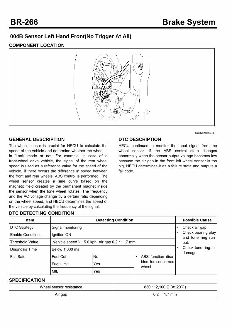
004B Sensor Left Hand Front(No Trigger At All)COMPONENT LOCATION
SUDWAB9049L
GENERAL DESCRIPTIONThe wheel sensor is crucial for HECU to calculate thespeed of the vehicle and determine whether the wheel isin 'Lock' mode or not. For example, in case of afront-wheel drive vehicle, the signal of the rear wheelspeed is used as a reference value for the speed of thevehicle. If there occurs the difference in speed betweenthe front and rear wheels, ABS control is performed. Thewheel sensor creates a sine curve based on themagnetic field created by the permanent magnet insidethe sensor when the tone wheel rotates. The frequencyand the AC voltage change by a certain ratio dependingon the wheel speed, and HECU determines the speed ofthe vehicle by calculating the frequency of the signal.
DTC DESCRIPTIONHECU continues to monitor the input signal from thewheel sensor. If the ABS control state changesabnormally when the sensor output voltage becomes lowbecause the air gap in the front left wheel sensor is toobig, HECU determines it as a failure state and outputs afail code.
DTC DETECTING CONDITIONItem Detecting Condition Possible Cause
DTC Strategy Signal monitoring • Check air gap.• Check bearing playand tone ring runout.
• Check tone ring fordamage.
Enable Conditions Ignition ON
Threshold Value .Vehicle speed > 15.0 kph. Air gap 0.2 ~ 1.7 mm
Diagnosis Time Below 1,000 ms
Fail Safe Fuel Cut No • ABS function disa-bled for concernedwheel
Fuel Limit Yes
MIL Yes
SPECIFICATIONWheel sensor resistance 830 ~ 2,100 Ω (At 20)
Air gap 0.2 ~ 1.7 mm
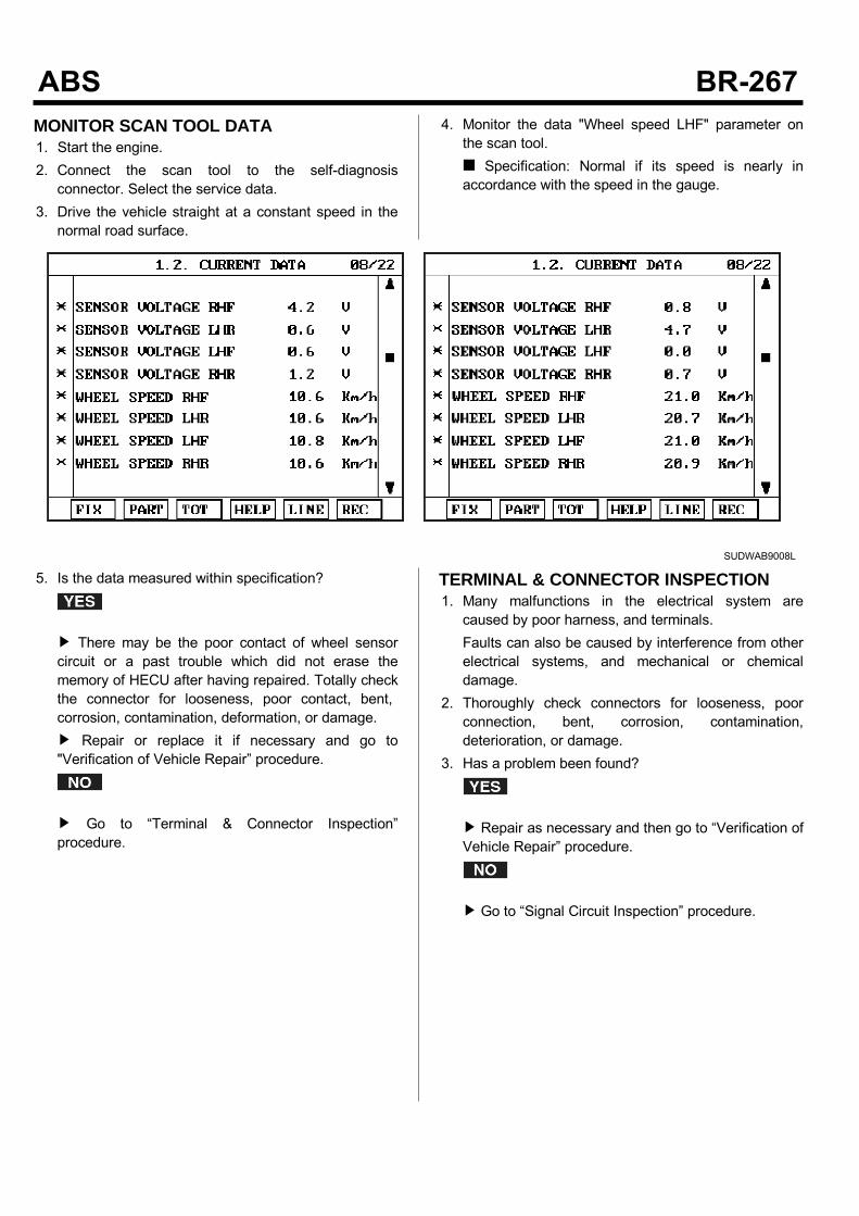
MONITOR SCAN TOOL DATA1. Start the engine.2. Connect the scan tool to the self-diagnosisconnector. Select the service data.
3. Drive the vehicle straight at a constant speed in thenormal road surface.
4. Monitor the data "Wheel speed LHF" parameter onthe scan tool. Specification: Normal if its speed is nearly inaccordance with the speed in the gauge.
SUDWAB9008L
5. Is the data measured within specification?
There may be the poor contact of wheel sensorcircuit or a past trouble which did not erase thememory of HECU after having repaired. Totally checkthe connector for looseness, poor contact, bent,corrosion, contamination, deformation, or damage. Repair or replace it if necessary and go to"Verification of Vehicle Repair” procedure.
Go to “Terminal & Connector Inspection”procedure.
TERMINAL & CONNECTOR INSPECTION1. Many malfunctions in the electrical system arecaused by poor harness, and terminals.Faults can also be caused by interference from otherelectrical systems, and mechanical or chemicaldamage.
2. Thoroughly check connectors for looseness, poorconnection, bent, corrosion, contamination,deterioration, or damage.
3. Has a problem been found?
Repair as necessary and then go to “Verification ofVehicle Repair” procedure.
Go to “Signal Circuit Inspection” procedure.
COMPONENT INSPECTIONLeft Hand Front Wheel Sensor Inspection1. Turn the ignition OFF.2. Disconnect the left hand front connector (C31).3. Measure the resistance between terminal positive (+)and terminal negative (-) of the left hand front wheelsensor. Specification: 830 ~ 2,100 Ω (At 20)
4. Is the resistance measured within specification?
After checking the HECU for contamination ordamage, install a known-good HECU and check itgood or not. Replace the HECU if the vehicle is normalcondition and go to "Verification of Vehicle Repair”procedure.
Replace the sensor if the vehicle is normal aftertemporarily installing a known-good sensor and go to"Verification of Vehicle Repair” procedure.
VERIFICATION OF VEHICLE REPAIRAfter a repair, it is essential to verify that the fault hasbeen corrected.1. Connect the scan tool and perform the self diagnosis.Check diagnostic trouble codes.
2. Clear the diagnostic trouble codes (DTCs) stored inthe ECM by using the scan tool.
3. Drive the vehicle under conditions noted in failurerecords.
4. Check that there are any DTCs by performing selfdiagnosis with the scan tool.
5. Did the DTC return?
Go to the applicable DTC procedure.
System OK
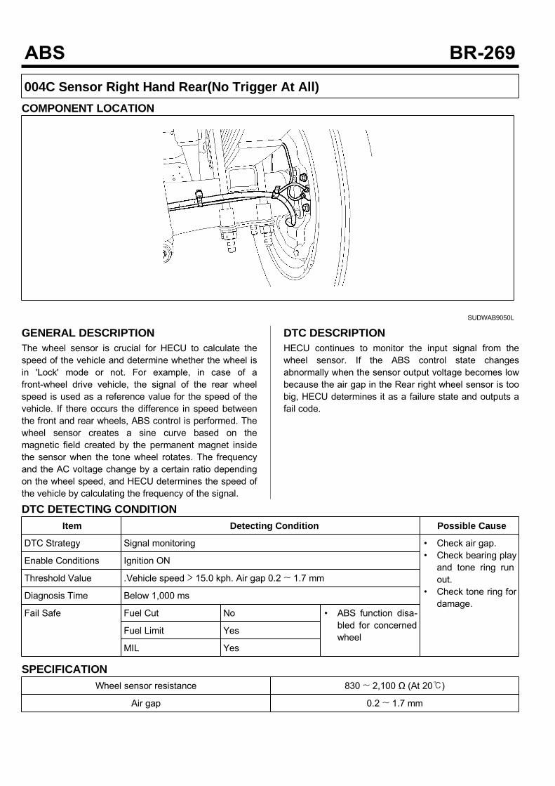
004C Sensor Right Hand Rear(No Trigger At All)COMPONENT LOCATION
SUDWAB9050L
GENERAL DESCRIPTIONThe wheel sensor is crucial for HECU to calculate thespeed of the vehicle and determine whether the wheel isin 'Lock' mode or not. For example, in case of afront-wheel drive vehicle, the signal of the rear wheelspeed is used as a reference value for the speed of thevehicle. If there occurs the difference in speed betweenthe front and rear wheels, ABS control is performed. Thewheel sensor creates a sine curve based on themagnetic field created by the permanent magnet insidethe sensor when the tone wheel rotates. The frequencyand the AC voltage change by a certain ratio dependingon the wheel speed, and HECU determines the speed ofthe vehicle by calculating the frequency of the signal.
DTC DESCRIPTIONHECU continues to monitor the input signal from thewheel sensor. If the ABS control state changesabnormally when the sensor output voltage becomes lowbecause the air gap in the Rear right wheel sensor is toobig, HECU determines it as a failure state and outputs afail code.
DTC DETECTING CONDITIONItem Detecting Condition Possible Cause
DTC Strategy Signal monitoring • Check air gap.• Check bearing playand tone ring runout.
• Check tone ring fordamage.
Enable Conditions Ignition ON
Threshold Value .Vehicle speed > 15.0 kph. Air gap 0.2 ~ 1.7 mm
Diagnosis Time Below 1,000 ms
Fail Safe Fuel Cut No • ABS function disa-bled for concernedwheel
Fuel Limit Yes
MIL Yes
SPECIFICATIONWheel sensor resistance 830 ~ 2,100 Ω (At 20)
Air gap 0.2 ~ 1.7 mm

MONITOR SCAN TOOL DATA1. Start the engine.2. Connect the scan tool to the self-diagnosisconnector. Select the service data.
3. Drive the vehicle straight at a constant speed in thenormal road surface.
4. Monitor the data "Wheel speed RHR" parameter onthe scan tool. Specification: Normal if its speed is nearly inaccordance with the speed in the gauge.
SUDWAB9008L
5. Is the data measured within specification?
There may be the poor contact of wheel sensorcircuit or a past trouble which did not erase thememory of HECU after having repaired. Totally checkthe connector for looseness, poor contact, bent,corrosion, contamination, deformation, or damage. Repair or replace it if necessary and go to"Verification of Vehicle Repair” procedure.
Go to “Terminal & Connector Inspection”procedure.
TERMINAL & CONNECTOR INSPECTION1. Many malfunctions in the electrical system arecaused by poor harness, and terminals.Faults can also be caused by interference from otherelectrical systems, and mechanical or chemicaldamage.
2. Thoroughly check connectors for looseness, poorconnection, bent, corrosion, contamination,deterioration, or damage.
3. Has a problem been found?
Repair as necessary and then go to “Verification ofVehicle Repair” procedure.
Go to “Signal Circuit Inspection” procedure.

COMPONENT INSPECTIONRight hand rear Wheel Sensor Inspection1. Turn the ignition OFF.2. Disconnect the right hand rear connector (C36).3. Measure the resistance between terminal positive (+)and terminal negative (-) of the right hand rear wheelsensor (C36). Specification: 830 ~ 2100 Ω (At 20)
4. Is the resistance measured within specification?
After checking the HECU for contamination ordamage, install a known-good HECU and check itgood or not. Replace the HECU if the vehicle is normalcondition and go to "Verification of Vehicle Repair”procedure.
Replace the sensor if the vehicle is normal aftertemporarily installing a known-good sensor and go to"Verification of Vehicle Repair” procedure.
VERIFICATION OF VEHICLE REPAIRAfter a repair, it is essential to verify that the fault hasbeen corrected.1. Connect the scan tool and perform the self diagnosis.Check diagnostic trouble codes.
2. Clear the diagnostic trouble codes (DTCs) stored inthe ECM by using the scan tool.
3. Drive the vehicle under conditions noted in failurerecords.
4. Check that there are any DTCs by performing selfdiagnosis with the scan tool.
5. Did the DTC return?
Go to the applicable DTC procedure.
System OK

004D J1939 Internal ErrorCOMPONENT LOCATION
SUDWAB9001L
GENERAL DESCRIPTIONThe Antilock Brake System (ABS) prevents the skidphenomenon that may occurs during a sudden brakewhile the vehicle is driving or when there is snow orwater on the road. By preventing the wheels from stickingor skidding on the road while the brake is applied, ABSmaintains the directional stability of the vehicle, securesthe steer ability, provides the maximum braking power soas to reduce the braking distance and to pursue theoverall safety of the driver and passengers. As the maindevice to perform ABS' braking function, HECU consistsof an input amplifier circuit that processes the inputsignal, an ABS control and SAFETY circuit thatcalculates the control and performs FAIL SAFE, anoutput circuit that drives the pressure control valve, avoltage adjustment circuit that regulates the voltage, anda failure memory circuit that memorizes anymalfunctioning. In case of a system malfunctioning, thewarning light is turned on, and at the same time, thepower to the pressure control valve is cut off, and theoperation of ABS is stopped.
DTC DESCRIPTIONHECU continues to monitor the internal components,such as memory, input and output circuits. In case of anerror during the operation of the control system, HECUdetermines whether it is a failure state and outputs a failcode.

DTC DETECTING CONDITIONItem Detecting Condition Possible Cause
DTC Strategy Signal monitoring • Replace ECU.
Enable Conditions Ignition ON
Threshold Value When the HECU detects malfunction in the control system
Diagnosis Time Below 1,000 ms
Fail Safe Fuel Cut No • ABS disabled
Fuel Limit Yes
MIL Yes
MONITOR SCAN TOOL DATA1. Connect scan tool to the self-diagnosis connector.
2. Turn the ignition ON.3. Monitor the service data on the scan tool.
SUDWAB9007L
TERMINAL & CONNECTOR INSPECTION1. Many malfunctions in the electrical system arecaused by poor harness, and terminals.Faults can also be caused by interference from otherelectrical systems, and mechanical or chemicaldamage.
2. Thoroughly check connectors for looseness, poorconnection, bent, corrosion, contamination,deterioration, or damage.
3. Has a problem been found?
Repair as necessary and then go to “Verification ofVehicle Repair” procedure.
Go to “Signal Circuit Inspection” procedure.

COMPONENT INSPECTION1. Start the engine.2. Drive the vehicle with approx. 15km/h or higher.3. Turn the ignition ON. Leave the engine OFF.4. Connect the scan tool and check the diagnostictrouble codes by using self-diagnosis.
5. Using the scan tool erase the diagnostic troublecodes stored in the HECU.
6. Check that there are any diagnostic trouble codes byusing self-diagnosis with the scan tool.
7. Are any diagnostic trouble codes (DTCs) detected?
Check that the DTCs have disappeared afterreplacing with a known-good HECU. If the problemhas solved, we may guess the HECU is problem.Replace the HECU and go to “Verification of VehicleRepair” procedure.
There may be a defective valve component or atransient trouble due to a past trouble which did noterase the memory of HECU after having repair. Andgo to "Verification of Vehicle Repair” procedure.
VERIFICATION OF VEHICLE REPAIRAfter a repair, it is essential to verify that the fault hasbeen corrected.1. Connect the scan tool and perform the self diagnosis.Check diagnostic trouble codes.
2. Clear the diagnostic trouble codes (DTCs) stored inthe ECM by using the scan tool.
3. Drive the vehicle under conditions noted in failurerecords.
4. Check that there are any DTCs by performing selfdiagnosis with the scan tool.
5. Did the DTC return?
Go to the applicable DTC procedure.
System OK

004E J1939 BusCOMPONENT LOCATION
SUDWAB9001L
GENERAL DESCRIPTIONThe Antilock Brake System (ABS) prevents the skidphenomenon that may occurs during a sudden brakewhile the vehicle is driving or when there is snow orwater on the road. By preventing the wheels from stickingor skidding on the road while the brake is applied, ABSmaintains the directional stability of the vehicle, securesthe steer ability, provides the maximum braking power soas to reduce the braking distance and to pursue theoverall safety of the driver and passengers. As the maindevice to perform ABS' braking function, HECU consistsof an input amplifier circuit that processes the inputsignal, an ABS control and SAFETY circuit thatcalculates the control and performs FAIL SAFE, anoutput circuit that drives the pressure control valve, avoltage adjustment circuit that regulates the voltage, anda failure memory circuit that memorizes anymalfunctioning. In case of a system malfunctioning, thewarning light is turned on, and at the same time, thepower to the pressure control valve is cut off, and theoperation of ABS is stopped.
DTC DESCRIPTIONHECU continues to monitor the internal components,such as memory, input and output circuits. In case of anerror during the operation of the control system, HECUdetermines whether it is a failure state and outputs a failcode.

DTC DETECTING CONDITIONItem Detecting Condition Possible Cause
DTC Strategy Signal monitoring • Replace ECU.
Enable Conditions Ignition ON
Threshold Value When the HECU detects malfunction in the control system
Diagnosis Time Below 1,000 ms
Fail Safe Fuel Cut No • ABS disabled
Fuel Limit Yes
MIL Yes
MONITOR SCAN TOOL DATA1. Connect scan tool to the self-diagnosis connector.
2. Turn the ignition ON.3. Monitor the service data on the scan tool.
SUDWAB9007L
TERMINAL & CONNECTOR INSPECTION1. Many malfunctions in the electrical system arecaused by poor harness, and terminals.Faults can also be caused by interference from otherelectrical systems, and mechanical or chemicaldamage.
2. Thoroughly check connectors for looseness, poorconnection, bent, corrosion, contamination,deterioration, or damage.
3. Has a problem been found?
Repair as necessary and then go to “Verification ofVehicle Repair” procedure.
Go to “Signal Circuit Inspection” procedure.

COMPONENT INSPECTION1. Start the engine.2. Drive the vehicle with approx. 15km/h or higher.3. Turn the ignition ON. Leave the engine OFF.4. Connect the scan tool and check the diagnostictrouble codes by using self-diagnosis.
5. Using the scan tool erase the diagnostic troublecodes stored in the HECU.
6. Check that there are any diagnostic trouble codes byusing self-diagnosis with the scan tool.
7. Are any diagnostic trouble codes (DTCs) detected?
Check that the DTCs have disappeared afterreplacing with a known-good HECU. If the problemhas solved, we may guess the HECU is problem.Replace the HECU and go to “Verification of VehicleRepair” procedure.
There may be a defective valve component or atransient trouble due to a past trouble which did noterase the memory of HECU after having repair. Andgo to "Verification of Vehicle Repair” procedure.
VERIFICATION OF VEHICLE REPAIRAfter a repair, it is essential to verify that the fault hasbeen corrected.1. Connect the scan tool and perform the self diagnosis.Check diagnostic trouble codes.
2. Clear the diagnostic trouble codes (DTCs) stored inthe ECM by using the scan tool.
3. Drive the vehicle under conditions noted in failurerecords.
4. Check that there are any DTCs by performing selfdiagnosis with the scan tool.
5. Did the DTC return?
Go to the applicable DTC procedure.
System OK

004F J1939 MessageCOMPONENT LOCATION
SUDWAB9001L
GENERAL DESCRIPTIONThe Antilock Brake System (ABS) prevents the skidphenomenon that may occurs during a sudden brakewhile the vehicle is driving or when there is snow orwater on the road. By preventing the wheels from stickingor skidding on the road while the brake is applied, ABSmaintains the directional stability of the vehicle, securesthe steer ability, provides the maximum braking power soas to reduce the braking distance and to pursue theoverall safety of the driver and passengers. As the maindevice to perform ABS' braking function, HECU consistsof an input amplifier circuit that processes the inputsignal, an ABS control and SAFETY circuit thatcalculates the control and performs FAIL SAFE, anoutput circuit that drives the pressure control valve, avoltage adjustment circuit that regulates the voltage, anda failure memory circuit that memorizes anymalfunctioning. In case of a system malfunctioning, thewarning light is turned on, and at the same time, thepower to the pressure control valve is cut off, and theoperation of ABS is stopped.
DTC DESCRIPTIONHECU continues to monitor the internal components,such as memory, input and output circuits. In case of anerror during the operation of the control system, HECUdetermines whether it is a failure state and outputs a failcode.

DTC DETECTING CONDITIONItem Detecting Condition Possible Cause
DTC Strategy Signal monitoring • Replace ECU.
Enable Conditions Ignition ON
Threshold Value When the HECU detects malfunction in the control system
Diagnosis Time Below 1,000 ms
Fail Safe Fuel Cut No • ABS disabled
Fuel Limit Yes
MIL Yes
MONITOR SCAN TOOL DATA1. Connect scan tool to the self-diagnosis connector.
2. Turn the ignition ON.3. Monitor the service data on the scan tool.
SUDWAB9007L
TERMINAL & CONNECTOR INSPECTION1. Many malfunctions in the electrical system arecaused by poor harness, and terminals.Faults can also be caused by interference from otherelectrical systems, and mechanical or chemicaldamage.
2. Thoroughly check connectors for looseness, poorconnection, bent, corrosion, contamination,deterioration, or damage.
3. Has a problem been found?
Repair as necessary and then go to “Verification ofVehicle Repair” procedure.
Go to “Signal Circuit Inspection” procedure.

COMPONENT INSPECTION1. Start the engine.2. Drive the vehicle with approx. 15km/h or higher.3. Turn the ignition ON. Leave the engine OFF.4. Connect the scan tool and check the diagnostictrouble codes by using self-diagnosis.
5. Using the scan tool erase the diagnostic troublecodes stored in the HECU.
6. Check that there are any diagnostic trouble codes byusing self-diagnosis with the scan tool.
7. Are any diagnostic trouble codes (DTCs) detected?
Check that the DTCs have disappeared afterreplacing with a known-good HECU. If the problemhas solved, we may guess the HECU is problem.Replace the HECU and go to “Verification of VehicleRepair” procedure.
There may be a defective valve component or atransient trouble due to a past trouble which did noterase the memory of HECU after having repair. Andgo to "Verification of Vehicle Repair” procedure.
VERIFICATION OF VEHICLE REPAIRAfter a repair, it is essential to verify that the fault hasbeen corrected.1. Connect the scan tool and perform the self diagnosis.Check diagnostic trouble codes.
2. Clear the diagnostic trouble codes (DTCs) stored inthe ECM by using the scan tool.
3. Drive the vehicle under conditions noted in failurerecords.
4. Check that there are any DTCs by performing selfdiagnosis with the scan tool.
5. Did the DTC return?
Go to the applicable DTC procedure.
System OK
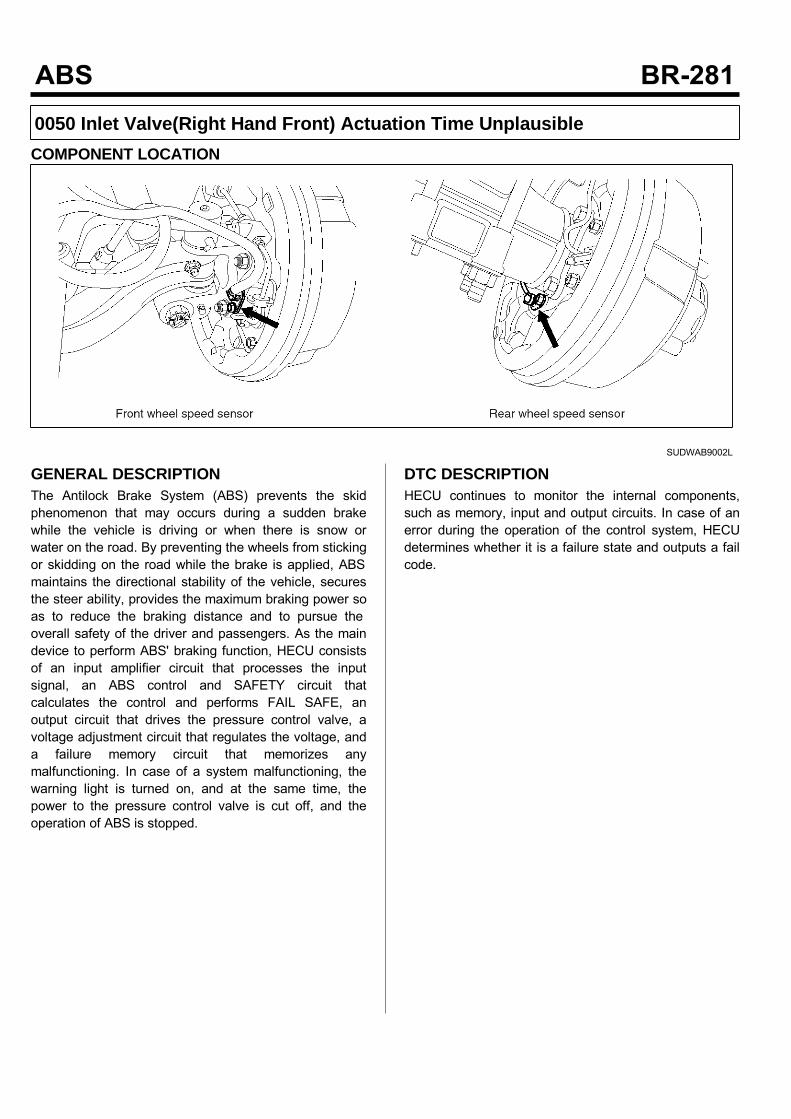
0050 Inlet Valve(Right Hand Front) Actuation Time UnplausibleCOMPONENT LOCATION
SUDWAB9002L
GENERAL DESCRIPTIONThe Antilock Brake System (ABS) prevents the skidphenomenon that may occurs during a sudden brakewhile the vehicle is driving or when there is snow orwater on the road. By preventing the wheels from stickingor skidding on the road while the brake is applied, ABSmaintains the directional stability of the vehicle, securesthe steer ability, provides the maximum braking power soas to reduce the braking distance and to pursue theoverall safety of the driver and passengers. As the maindevice to perform ABS' braking function, HECU consistsof an input amplifier circuit that processes the inputsignal, an ABS control and SAFETY circuit thatcalculates the control and performs FAIL SAFE, anoutput circuit that drives the pressure control valve, avoltage adjustment circuit that regulates the voltage, anda failure memory circuit that memorizes anymalfunctioning. In case of a system malfunctioning, thewarning light is turned on, and at the same time, thepower to the pressure control valve is cut off, and theoperation of ABS is stopped.
DTC DESCRIPTIONHECU continues to monitor the internal components,such as memory, input and output circuits. In case of anerror during the operation of the control system, HECUdetermines whether it is a failure state and outputs a failcode.
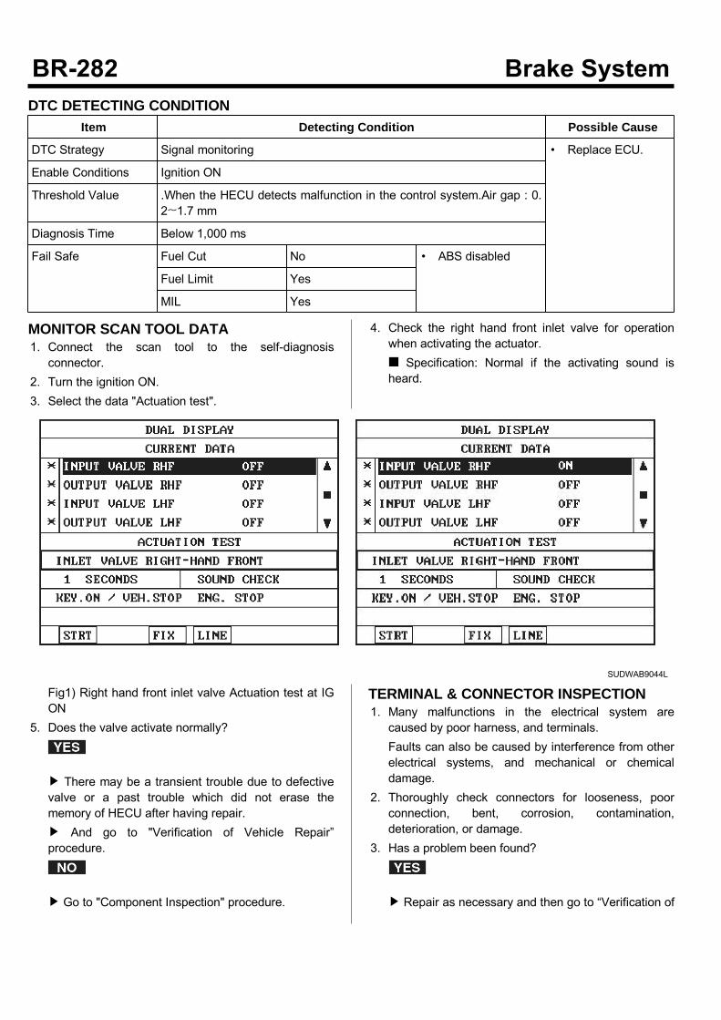
DTC DETECTING CONDITIONItem Detecting Condition Possible Cause
DTC Strategy Signal monitoring • Replace ECU.
Enable Conditions Ignition ON
Threshold Value .When the HECU detects malfunction in the control system.Air gap : 0.2~1.7 mm
Diagnosis Time Below 1,000 ms
Fail Safe Fuel Cut No • ABS disabled
Fuel Limit Yes
MIL Yes
MONITOR SCAN TOOL DATA1. Connect the scan tool to the self-diagnosisconnector.
2. Turn the ignition ON.3. Select the data "Actuation test".
4. Check the right hand front inlet valve for operationwhen activating the actuator. Specification: Normal if the activating sound isheard.
SUDWAB9044L
Fig1) Right hand front inlet valve Actuation test at IGON
5. Does the valve activate normally?
There may be a transient trouble due to defectivevalve or a past trouble which did not erase thememory of HECU after having repair. And go to "Verification of Vehicle Repair”procedure.
Go to "Component Inspection" procedure.
TERMINAL & CONNECTOR INSPECTION1. Many malfunctions in the electrical system arecaused by poor harness, and terminals.Faults can also be caused by interference from otherelectrical systems, and mechanical or chemicaldamage.
2. Thoroughly check connectors for looseness, poorconnection, bent, corrosion, contamination,deterioration, or damage.
3. Has a problem been found?
Repair as necessary and then go to “Verification of

Vehicle Repair” procedure.
Go to “Signal Circuit Inspection” procedure.
COMPONENT INSPECTION1. Start the engine.2. Drive the vehicle with approx. 15km/h or higher.3. Turn the ignition ON. Leave the engine OFF.4. Connect the scan tool and check the diagnostictrouble codes by using self-diagnosis.
5. Using the scan tool erase the diagnostic troublecodes stored in the HECU.
6. Check that there are any diagnostic trouble codes byusing self-diagnosis with the scan tool.
7. Are any diagnostic trouble codes (DTCs) detected?
Check that the DTCs have disappeared afterreplacing with a known-good HECU. If the problemhas solved, we may guess the HECU is problem.Replace the HECU and go to “Verification of VehicleRepair” procedure.
There may be a defective valve component or atransient trouble due to a past trouble which did noterase the memory of HECU after having repair. Andgo to "Verification of Vehicle Repair” procedure.
VERIFICATION OF VEHICLE REPAIRAfter a repair, it is essential to verify that the fault hasbeen corrected.1. Connect the scan tool and perform the self diagnosis.Check diagnostic trouble codes.
2. Clear the diagnostic trouble codes (DTCs) stored inthe ECM by using the scan tool.
3. Drive the vehicle under conditions noted in failurerecords.
4. Check that there are any DTCs by performing selfdiagnosis with the scan tool.
5. Did the DTC return?
Go to the applicable DTC procedure.
System OK

0051 Inlet Valve(Left Hand Rear) Actuation Time UnplausibleCOMPONENT LOCATION
SUDWAB9048L
GENERAL DESCRIPTIONThe Antilock Brake System (ABS) prevents the skidphenomenon that may occurs during a sudden brakewhile the vehicle is driving or when there is snow orwater on the road. By preventing the wheels from stickingor skidding on the road while the brake is applied, ABSmaintains the directional stability of the vehicle, securesthe steer ability, provides the maximum braking power soas to reduce the braking distance and to pursue theoverall safety of the driver and passengers. As the maindevice to perform ABS' braking function, HECU consistsof an input amplifier circuit that processes the inputsignal, an ABS control and SAFETY circuit thatcalculates the control and performs FAIL SAFE, anoutput circuit that drives the pressure control valve, avoltage adjustment circuit that regulates the voltage, anda failure memory circuit that memorizes anymalfunctioning. In case of a system malfunctioning, thewarning light is turned on, and at the same time, thepower to the pressure control valve is cut off, and theoperation of ABS is stopped.
DTC DESCRIPTIONHECU continues to monitor the internal components,such as memory, input and output circuits. In case of anerror during the operation of the control system, HECUdetermines whether it is a failure state and outputs a failcode.
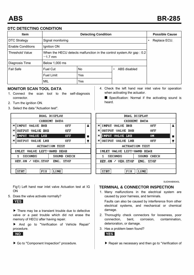
DTC DETECTING CONDITIONItem Detecting Condition Possible Cause
DTC Strategy Signal monitoring • Replace ECU.
Enable Conditions Ignition ON
Threshold Value When the HECU detects malfunction in the control system.Air gap : 0.2~1.7 mm
Diagnosis Time Below 1,000 ms
Fail Safe Fuel Cut No • ABS disabled
Fuel Limit Yes
MIL Yes
MONITOR SCAN TOOL DATA1. Connect the scan tool to the self-diagnosisconnector.
2. Turn the ignition ON.3. Select the data "Actuation test".
4. Check the left hand rear inlet valve for operationwhen activating the actuator. Specification: Normal if the activating sound isheard.
SUDWAB9045L
Fig1) Left hand rear inlet valve Actuation test at IGON
5. Does the valve activate normally?
There may be a transient trouble due to defectivevalve or a past trouble which did not erase thememory of HECU after having repair. And go to "Verification of Vehicle Repair”procedure.
Go to "Component Inspection" procedure.
TERMINAL & CONNECTOR INSPECTION1. Many malfunctions in the electrical system arecaused by poor harness, and terminals.Faults can also be caused by interference from otherelectrical systems, and mechanical or chemicaldamage.
2. Thoroughly check connectors for looseness, poorconnection, bent, corrosion, contamination,deterioration, or damage.
3. Has a problem been found?
Repair as necessary and then go to “Verification of

Vehicle Repair” procedure.
Go to “Signal Circuit Inspection” procedure.
COMPONENT INSPECTION1. Start the engine.2. Drive the vehicle with approx. 15km/h or higher.3. Turn the ignition ON. Leave the engine OFF.4. Connect the scan tool and check the diagnostictrouble codes by using self-diagnosis.
5. Using the scan tool erase the diagnostic troublecodes stored in the HECU.
6. Check that there are any diagnostic trouble codes byusing self-diagnosis with the scan tool.
7. Are any diagnostic trouble codes (DTCs) detected?
Check that the DTCs have disappeared afterreplacing with a known-good HECU. If the problemhas solved, we may guess the HECU is problem.Replace the HECU and go to “Verification of VehicleRepair” procedure.
There may be a defective valve component or atransient trouble due to a past trouble which did noterase the memory of HECU after having repair. Andgo to "Verification of Vehicle Repair” procedure.
VERIFICATION OF VEHICLE REPAIRAfter a repair, it is essential to verify that the fault hasbeen corrected.1. Connect the scan tool and perform the self diagnosis.Check diagnostic trouble codes.
2. Clear the diagnostic trouble codes (DTCs) stored inthe ECM by using the scan tool.
3. Drive the vehicle under conditions noted in failurerecords.
4. Check that there are any DTCs by performing selfdiagnosis with the scan tool.
5. Did the DTC return?
Go to the applicable DTC procedure.
System OK

0052 Inlet Valve(Left Hand Front) Actuation Time UnplausibleCOMPONENT LOCATION
SUDWAB9049L
GENERAL DESCRIPTIONThe Antilock Brake System (ABS) prevents the skidphenomenon that may occurs during a sudden brakewhile the vehicle is driving or when there is snow orwater on the road. By preventing the wheels from stickingor skidding on the road while the brake is applied, ABSmaintains the directional stability of the vehicle, securesthe steer ability, provides the maximum braking power soas to reduce the braking distance and to pursue theoverall safety of the driver and passengers. As the maindevice to perform ABS' braking function, HECU consistsof an input amplifier circuit that processes the inputsignal, an ABS control and SAFETY circuit thatcalculates the control and performs FAIL SAFE, anoutput circuit that drives the pressure control valve, avoltage adjustment circuit that regulates the voltage, anda failure memory circuit that memorizes anymalfunctioning. In case of a system malfunctioning, thewarning light is turned on, and at the same time, thepower to the pressure control valve is cut off, and theoperation of ABS is stopped.
DTC DESCRIPTIONHECU continues to monitor the internal components,such as memory, input and output circuits. In case of anerror during the operation of the control system, HECUdetermines whether it is a failure state and outputs a failcode.
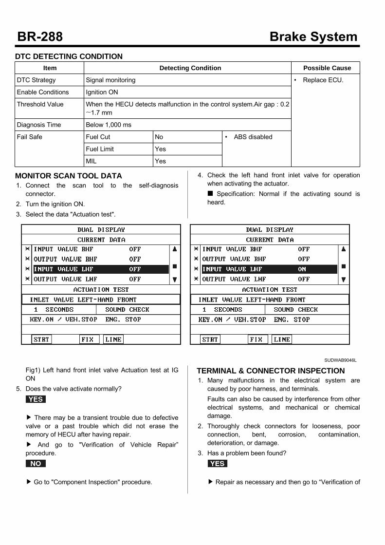
DTC DETECTING CONDITIONItem Detecting Condition Possible Cause
DTC Strategy Signal monitoring • Replace ECU.
Enable Conditions Ignition ON
Threshold Value When the HECU detects malfunction in the control system.Air gap : 0.2~1.7 mm
Diagnosis Time Below 1,000 ms
Fail Safe Fuel Cut No • ABS disabled
Fuel Limit Yes
MIL Yes
MONITOR SCAN TOOL DATA1. Connect the scan tool to the self-diagnosisconnector.
2. Turn the ignition ON.3. Select the data "Actuation test".
4. Check the left hand front inlet valve for operationwhen activating the actuator. Specification: Normal if the activating sound isheard.
SUDWAB9046L
Fig1) Left hand front inlet valve Actuation test at IGON
5. Does the valve activate normally?
There may be a transient trouble due to defectivevalve or a past trouble which did not erase thememory of HECU after having repair. And go to "Verification of Vehicle Repair”procedure.
Go to "Component Inspection" procedure.
TERMINAL & CONNECTOR INSPECTION1. Many malfunctions in the electrical system arecaused by poor harness, and terminals.Faults can also be caused by interference from otherelectrical systems, and mechanical or chemicaldamage.
2. Thoroughly check connectors for looseness, poorconnection, bent, corrosion, contamination,deterioration, or damage.
3. Has a problem been found?
Repair as necessary and then go to “Verification of
Vehicle Repair” procedure.
Go to “Signal Circuit Inspection” procedure.
COMPONENT INSPECTION1. Start the engine.2. Drive the vehicle with approx. 15km/h or higher.3. Turn the ignition ON. Leave the engine OFF.4. Connect the scan tool and check the diagnostictrouble codes by using self-diagnosis.
5. Using the scan tool erase the diagnostic troublecodes stored in the HECU.
6. Check that there are any diagnostic trouble codes byusing self-diagnosis with the scan tool.
7. Are any diagnostic trouble codes (DTCs) detected?
Check that the DTCs have disappeared afterreplacing with a known-good HECU. If the problemhas solved, we may guess the HECU is problem.Replace the HECU and go to “Verification of VehicleRepair” procedure.
There may be a defective valve component or atransient trouble due to a past trouble which did noterase the memory of HECU after having repair. Andgo to "Verification of Vehicle Repair” procedure.
VERIFICATION OF VEHICLE REPAIRAfter a repair, it is essential to verify that the fault hasbeen corrected.1. Connect the scan tool and perform the self diagnosis.Check diagnostic trouble codes.
2. Clear the diagnostic trouble codes (DTCs) stored inthe ECM by using the scan tool.
3. Drive the vehicle under conditions noted in failurerecords.
4. Check that there are any DTCs by performing selfdiagnosis with the scan tool.
5. Did the DTC return?
Go to the applicable DTC procedure.
System OK
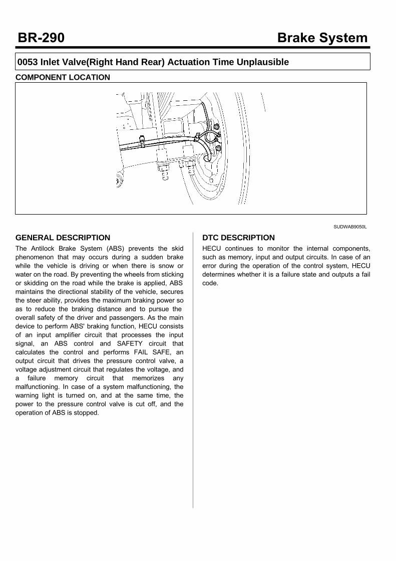
0053 Inlet Valve(Right Hand Rear) Actuation Time UnplausibleCOMPONENT LOCATION
SUDWAB9050L
GENERAL DESCRIPTIONThe Antilock Brake System (ABS) prevents the skidphenomenon that may occurs during a sudden brakewhile the vehicle is driving or when there is snow orwater on the road. By preventing the wheels from stickingor skidding on the road while the brake is applied, ABSmaintains the directional stability of the vehicle, securesthe steer ability, provides the maximum braking power soas to reduce the braking distance and to pursue theoverall safety of the driver and passengers. As the maindevice to perform ABS' braking function, HECU consistsof an input amplifier circuit that processes the inputsignal, an ABS control and SAFETY circuit thatcalculates the control and performs FAIL SAFE, anoutput circuit that drives the pressure control valve, avoltage adjustment circuit that regulates the voltage, anda failure memory circuit that memorizes anymalfunctioning. In case of a system malfunctioning, thewarning light is turned on, and at the same time, thepower to the pressure control valve is cut off, and theoperation of ABS is stopped.
DTC DESCRIPTIONHECU continues to monitor the internal components,such as memory, input and output circuits. In case of anerror during the operation of the control system, HECUdetermines whether it is a failure state and outputs a failcode.
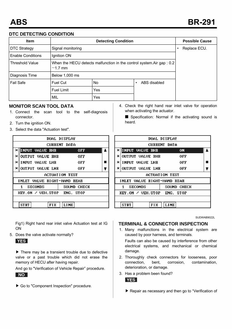
DTC DETECTING CONDITIONItem Detecting Condition Possible Cause
DTC Strategy Signal monitoring • Replace ECU.
Enable Conditions Ignition ON
Threshold Value When the HECU detects malfunction in the control system.Air gap : 0.2~1.7 mm
Diagnosis Time Below 1,000 ms
Fail Safe Fuel Cut No • ABS disabled
Fuel Limit Yes
MIL Yes
MONITOR SCAN TOOL DATA1. Connect the scan tool to the self-diagnosisconnector.
2. Turn the ignition ON.3. Select the data "Actuation test".
4. Check the right hand rear inlet valve for operationwhen activating the actuator. Specification: Normal if the activating sound isheard.
SUDWAB9022L
Fig1) Right hand rear inlet valve Actuation test at IGON
5. Does the valve activate normally?
There may be a transient trouble due to defectivevalve or a past trouble which did not erase thememory of HECU after having repair.And go to "Verification of Vehicle Repair” procedure.
Go to "Component Inspection" procedure.
TERMINAL & CONNECTOR INSPECTION1. Many malfunctions in the electrical system arecaused by poor harness, and terminals.Faults can also be caused by interference from otherelectrical systems, and mechanical or chemicaldamage.
2. Thoroughly check connectors for looseness, poorconnection, bent, corrosion, contamination,deterioration, or damage.
3. Has a problem been found?
Repair as necessary and then go to “Verification of
Vehicle Repair” procedure.
Go to “Signal Circuit Inspection” procedure.
COMPONENT INSPECTION1. Start the engine.2. Drive the vehicle with approx. 15km/h or higher.3. Turn the ignition ON. Leave the engine OFF.4. Connect the scan tool and check the diagnostictrouble codes by using self-diagnosis.
5. Using the scan tool erase the diagnostic troublecodes stored in the HECU.
6. Check that there are any diagnostic trouble codes byusing self-diagnosis with the scan tool.
7. Are any diagnostic trouble codes (DTCs) detected?
Check that the DTCs have disappeared afterreplacing with a known-good HECU. If the problemhas solved, we may guess the HECU is problem.Replace the HECU and go to “Verification of VehicleRepair” procedure.
There may be a defective valve component or atransient trouble due to a past trouble which did noterase the memory of HECU after having repair. Andgo to "Verification of Vehicle Repair” procedure.
VERIFICATION OF VEHICLE REPAIRAfter a repair, it is essential to verify that the fault hasbeen corrected.1. Connect the scan tool and perform the self diagnosis.Check diagnostic trouble codes.
2. Clear the diagnostic trouble codes (DTCs) stored inthe ECM by using the scan tool.
3. Drive the vehicle under conditions noted in failurerecords.
4. Check that there are any DTCs by performing selfdiagnosis with the scan tool.
5. Did the DTC return?
Go to the applicable DTC procedure.
System OK
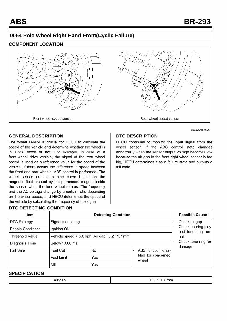
0054 Pole Wheel Right Hand Front(Cyclic Failure)COMPONENT LOCATION
SUDWAB9002L
GENERAL DESCRIPTIONThe wheel sensor is crucial for HECU to calculate thespeed of the vehicle and determine whether the wheel isin 'Lock' mode or not. For example, in case of afront-wheel drive vehicle, the signal of the rear wheelspeed is used as a reference value for the speed of thevehicle. If there occurs the difference in speed betweenthe front and rear wheels, ABS control is performed. Thewheel sensor creates a sine curve based on themagnetic field created by the permanent magnet insidethe sensor when the tone wheel rotates. The frequencyand the AC voltage change by a certain ratio dependingon the wheel speed, and HECU determines the speed ofthe vehicle by calculating the frequency of the signal.
DTC DESCRIPTIONHECU continues to monitor the input signal from thewheel sensor. If the ABS control state changesabnormally when the sensor output voltage becomes lowbecause the air gap in the front right wheel sensor is toobig, HECU determines it as a failure state and outputs afail code.
DTC DETECTING CONDITIONItem Detecting Condition Possible Cause
DTC Strategy Signal monitoring • Check air gap.• Check bearing playand tone ring runout.
• Check tone ring fordamage.
Enable Conditions Ignition ON
Threshold Value Vehicle speed > 5.0 kph. Air gap : 0.2~1.7 mm
Diagnosis Time Below 1,000 ms
Fail Safe Fuel Cut No • ABS function disa-bled for concernedwheel
Fuel Limit Yes
MIL Yes
SPECIFICATIONAir gap 0.2 ~ 1.7 mm
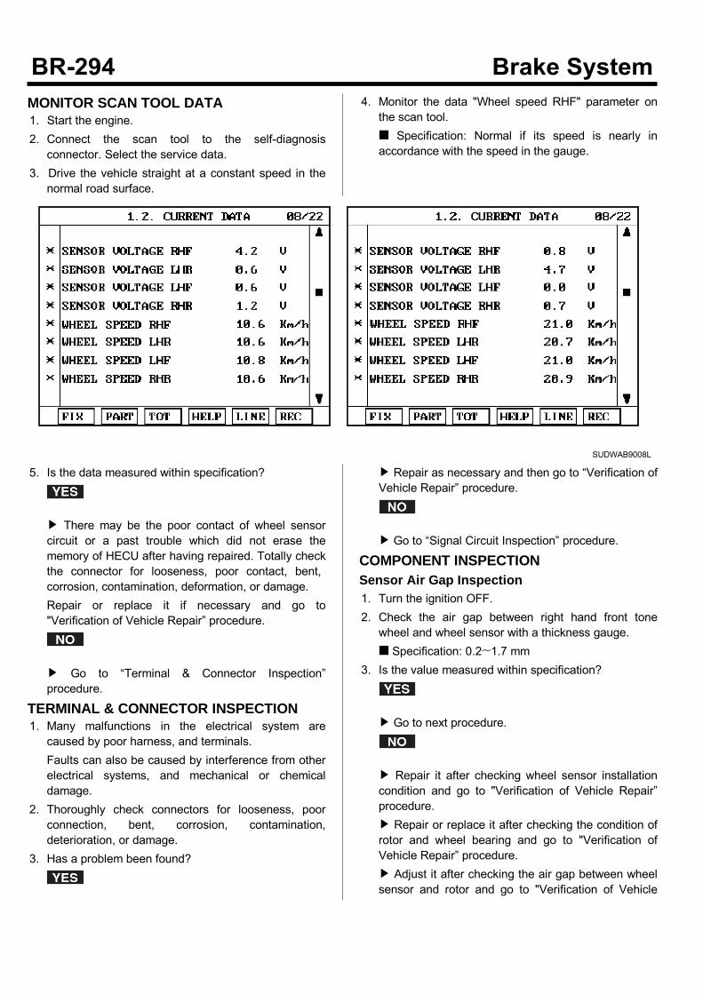
MONITOR SCAN TOOL DATA1. Start the engine.2. Connect the scan tool to the self-diagnosisconnector. Select the service data.
3. Drive the vehicle straight at a constant speed in thenormal road surface.
4. Monitor the data "Wheel speed RHF" parameter onthe scan tool. Specification: Normal if its speed is nearly inaccordance with the speed in the gauge.
SUDWAB9008L
5. Is the data measured within specification?
There may be the poor contact of wheel sensorcircuit or a past trouble which did not erase thememory of HECU after having repaired. Totally checkthe connector for looseness, poor contact, bent,corrosion, contamination, deformation, or damage.Repair or replace it if necessary and go to"Verification of Vehicle Repair” procedure.
Go to “Terminal & Connector Inspection”procedure.
TERMINAL & CONNECTOR INSPECTION1. Many malfunctions in the electrical system arecaused by poor harness, and terminals.Faults can also be caused by interference from otherelectrical systems, and mechanical or chemicaldamage.
2. Thoroughly check connectors for looseness, poorconnection, bent, corrosion, contamination,deterioration, or damage.
3. Has a problem been found?
Repair as necessary and then go to “Verification ofVehicle Repair” procedure.
Go to “Signal Circuit Inspection” procedure.
COMPONENT INSPECTIONSensor Air Gap Inspection1. Turn the ignition OFF.2. Check the air gap between right hand front tonewheel and wheel sensor with a thickness gauge. Specification: 0.2~1.7 mm
3. Is the value measured within specification?
Go to next procedure.
Repair it after checking wheel sensor installationcondition and go to "Verification of Vehicle Repair”procedure. Repair or replace it after checking the condition ofrotor and wheel bearing and go to "Verification ofVehicle Repair” procedure. Adjust it after checking the air gap between wheelsensor and rotor and go to "Verification of Vehicle
Repair” procedure.Check Number of Teeth on Tone Ring1. Turn the ignition OFF.2. Check the number of teeth on right hand front tonering.
3. Is the number of teeth normal?
Go to "Verification of Vehicle Repair” procedure.
Repair it or replace with known-good one andcheck the condition of vehicle. If normal, replace with new one. And go to"Verification of Vehicle Repair” procedure.
VERIFICATION OF VEHICLE REPAIRAfter a repair, it is essential to verify that the fault hasbeen corrected.1. Connect the scan tool and perform the self diagnosis.Check diagnostic trouble codes.
2. Clear the diagnostic trouble codes (DTCs) stored inthe ECM by using the scan tool.
3. Drive the vehicle under conditions noted in failurerecords.
4. Check that there are any DTCs by performing selfdiagnosis with the scan tool.
5. Did the DTC return?
Go to the applicable DTC procedure.
System OK
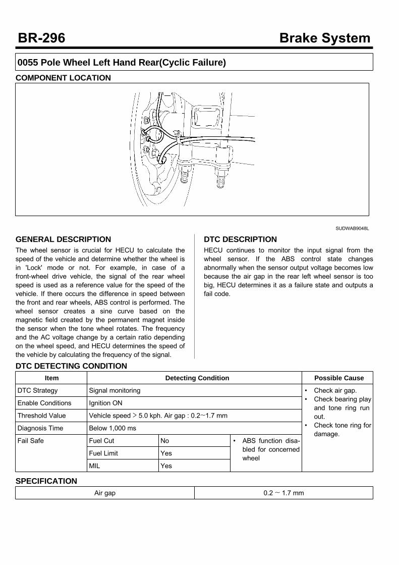
0055 Pole Wheel Left Hand Rear(Cyclic Failure)COMPONENT LOCATION
SUDWAB9048L
GENERAL DESCRIPTIONThe wheel sensor is crucial for HECU to calculate thespeed of the vehicle and determine whether the wheel isin 'Lock' mode or not. For example, in case of afront-wheel drive vehicle, the signal of the rear wheelspeed is used as a reference value for the speed of thevehicle. If there occurs the difference in speed betweenthe front and rear wheels, ABS control is performed. Thewheel sensor creates a sine curve based on themagnetic field created by the permanent magnet insidethe sensor when the tone wheel rotates. The frequencyand the AC voltage change by a certain ratio dependingon the wheel speed, and HECU determines the speed ofthe vehicle by calculating the frequency of the signal.
DTC DESCRIPTIONHECU continues to monitor the input signal from thewheel sensor. If the ABS control state changesabnormally when the sensor output voltage becomes lowbecause the air gap in the rear left wheel sensor is toobig, HECU determines it as a failure state and outputs afail code.
DTC DETECTING CONDITIONItem Detecting Condition Possible Cause
DTC Strategy Signal monitoring • Check air gap.• Check bearing playand tone ring runout.
• Check tone ring fordamage.
Enable Conditions Ignition ON
Threshold Value Vehicle speed > 5.0 kph. Air gap : 0.2~1.7 mm
Diagnosis Time Below 1,000 ms
Fail Safe Fuel Cut No • ABS function disa-bled for concernedwheel
Fuel Limit Yes
MIL Yes
SPECIFICATIONAir gap 0.2 ~ 1.7 mm

MONITOR SCAN TOOL DATA1. Start the engine.2. Connect the scan tool to the self-diagnosisconnector. Select the service data.
3. Drive the vehicle straight at a constant speed in thenormal road surface.
4. Monitor the data "Wheel speed LHR" parameter onthe scan tool. Specification: Normal if its speed is nearly inaccordance with the speed in the gauge.
SUDWAB9008L
5. Is the data measured within specification?
There may be the poor contact of wheel sensorcircuit or a past trouble which did not erase thememory of HECU after having repaired. Totally checkthe connector for looseness, poor contact, bent,corrosion, contamination, deformation, or damage. Repair or replace it if necessary and go to"Verification of Vehicle Repair” procedure.
Go to “Terminal & Connector Inspection”procedure.
TERMINAL & CONNECTOR INSPECTION1. Many malfunctions in the electrical system arecaused by poor harness, and terminals.Faults can also be caused by interference from otherelectrical systems, and mechanical or chemicaldamage.
2. Thoroughly check connectors for looseness, poorconnection, bent, corrosion, contamination,deterioration, or damage.
3. Has a problem been found?
Repair as necessary and then go to “Verification ofVehicle Repair” procedure.
Go to “Signal Circuit Inspection” procedure.
COMPONENT INSPECTIONSensor Air Gap Inspection1. Turn the ignition OFF.2. Check the air gap between left hand rear tone wheeland wheel sensor with a thickness gauge. Specification: 0.2~1.7 mm
3. Is the value measured within specification?
Go to next procedure.
Repair it after checking wheel sensor installationcondition and go to "Verification of Vehicle Repair”procedure. Repair or replace it after checking the condition ofrotor and wheel bearing and go to "Verification ofVehicle Repair” procedure. Adjust it after checking the air gap between wheelsensor and rotor and go to "Verification of Vehicle
Repair” procedure.Check Number of Teeth on Tone Ring1. Turn the ignition OFF.2. Check the number of teeth on left hand rear tonering.
3. Is the number of teeth normal?
Go to "Verification of Vehicle Repair” procedure.
Repair it or replace with known-good one andcheck the condition of vehicle. If normal, replace with new one. And go to"Verification of Vehicle Repair” procedure.
VERIFICATION OF VEHICLE REPAIRAfter a repair, it is essential to verify that the fault hasbeen corrected.1. Connect the scan tool and perform the self diagnosis.Check diagnostic trouble codes.
2. Clear the diagnostic trouble codes (DTCs) stored inthe ECM by using the scan tool.
3. Drive the vehicle under conditions noted in failurerecords.
4. Check that there are any DTCs by performing selfdiagnosis with the scan tool.
5. Did the DTC return?
Go to the applicable DTC procedure.
System OK

0056 Pole Wheel Left Hand Front(Cyclic Failure)COMPONENT LOCATION
SUDWAB9049L
GENERAL DESCRIPTIONThe wheel sensor is crucial for HECU to calculate thespeed of the vehicle and determine whether the wheel isin 'Lock' mode or not. For example, in case of afront-wheel drive vehicle, the signal of the rear wheelspeed is used as a reference value for the speed of thevehicle. If there occurs the difference in speed betweenthe front and rear wheels, ABS control is performed. Thewheel sensor creates a sine curve based on themagnetic field created by the permanent magnet insidethe sensor when the tone wheel rotates. The frequencyand the AC voltage change by a certain ratio dependingon the wheel speed, and HECU determines the speed ofthe vehicle by calculating the frequency of the signal.
DTC DESCRIPTIONHECU continues to monitor the input signal from thewheel sensor. If the ABS control state changesabnormally when the sensor output voltage becomes lowbecause the air gap in the front left wheel sensor is toobig, HECU determines it as a failure state and outputs afail code.
DTC DETECTING CONDITIONItem Detecting Condition Possible Cause
DTC Strategy Signal monitoring • Check air gap.• Check bearing playand tone ring runout.
• Check tone ring fordamage.
Enable Conditions Ignition ON
Threshold Value Vehicle speed > 5.0 kph. Air gap : 0.2~1.7 mm
Diagnosis Time Below 1,000 ms
Fail Safe Fuel Cut No • ABS function disa-bled for concernedwheel.
Fuel Limit Yes
MIL Yes
SPECIFICATIONAir gap 0.2 ~ 1.7 mm

MONITOR SCAN TOOL DATA1. Start the engine.2. Connect the scan tool to the self-diagnosisconnector. Select the service data.
3. Drive the vehicle straight at a constant speed in thenormal road surface.
4. Monitor the data "Wheel speed LHF" parameter onthe scan tool. Specification: Normal if its speed is nearly inaccordance with the speed in the gauge.
SUDWAB9008L
5. Is the data measured within specification?
There may be the poor contact of wheel sensorcircuit or a past trouble which did not erase thememory of HECU after having repaired. Totally checkthe connector for looseness, poor contact, bent,corrosion, contamination, deformation, or damage. Repair or replace it if necessary and go to"Verification of Vehicle Repair” procedure.
Go to “Terminal & Connector Inspection”procedure.
TERMINAL & CONNECTOR INSPECTION1. Many malfunctions in the electrical system arecaused by poor harness, and terminals.Faults can also be caused by interference from otherelectrical systems, and mechanical or chemicaldamage.
2. Thoroughly check connectors for looseness, poorconnection, bent, corrosion, contamination,deterioration, or damage.
3. Has a problem been found?
Repair as necessary and then go to “Verification ofVehicle Repair” procedure.
Go to “Signal Circuit Inspection” procedure.
COMPONENT INSPECTIONSensor Air Gap Inspection1. Turn the ignition OFF.2. Check the air gap between left hand front tone wheeland wheel sensor with a thickness gauge. Specification: 0.2~1.7mm
3. Is the value measured within specification?
Go to next procedure.
Repair it after checking wheel sensor installationcondition and go to "Verification of Vehicle Repair”procedure. Repair or replace it after checking the condition ofrotor and wheel bearing and go to "Verification ofVehicle Repair” procedure. Adjust it after checking the air gap between wheelsensor and rotor and go to "Verification of Vehicle

Repair” procedure.Check Number of Teeth on Tone Ring1. Turn the ignition OFF.2. Check the number of teeth on left hand front tonering.
3. Is the number of teeth normal?
Go to "Verification of Vehicle Repair” procedure.
Repair it or replace with known-good one andcheck the condition of vehicle. If normal, replace with new one. And go to"Verification of Vehicle Repair” procedure.
VERIFICATION OF VEHICLE REPAIRAfter a repair, it is essential to verify that the fault hasbeen corrected.1. Connect the scan tool and perform the self diagnosis.Check diagnostic trouble codes.
2. Clear the diagnostic trouble codes (DTCs) stored inthe ECM by using the scan tool.
3. Drive the vehicle under conditions noted in failurerecords.
4. Check that there are any DTCs by performing selfdiagnosis with the scan tool.
5. Did the DTC return?
Go to the applicable DTC procedure.
System OK
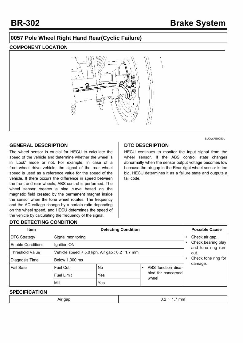
0057 Pole Wheel Right Hand Rear(Cyclic Failure)COMPONENT LOCATION
SUDWAB9050L
GENERAL DESCRIPTIONThe wheel sensor is crucial for HECU to calculate thespeed of the vehicle and determine whether the wheel isin 'Lock' mode or not. For example, in case of afront-wheel drive vehicle, the signal of the rear wheelspeed is used as a reference value for the speed of thevehicle. If there occurs the difference in speed betweenthe front and rear wheels, ABS control is performed. Thewheel sensor creates a sine curve based on themagnetic field created by the permanent magnet insidethe sensor when the tone wheel rotates. The frequencyand the AC voltage change by a certain ratio dependingon the wheel speed, and HECU determines the speed ofthe vehicle by calculating the frequency of the signal.
DTC DESCRIPTIONHECU continues to monitor the input signal from thewheel sensor. If the ABS control state changesabnormally when the sensor output voltage becomes lowbecause the air gap in the Rear right wheel sensor is toobig, HECU determines it as a failure state and outputs afail code.
DTC DETECTING CONDITIONItem Detecting Condition Possible Cause
DTC Strategy Signal monitoring • Check air gap.• Check bearing playand tone ring runout.
• Check tone ring fordamage.
Enable Conditions Ignition ON
Threshold Value Vehicle speed > 5.0 kph. Air gap : 0.2~1.7 mm
Diagnosis Time Below 1,000 ms
Fail Safe Fuel Cut No • ABS function disa-bled for concernedwheel
Fuel Limit Yes
MIL Yes
SPECIFICATIONAir gap 0.2 ~ 1.7 mm

MONITOR SCAN TOOL DATA1. Start the engine.2. Connect the scan tool to the self-diagnosisconnector. Select the service data.
3. Drive the vehicle straight at a constant speed in thenormal road surface.
4. Monitor the data "Wheel speed RHR" parameter onthe scan tool. Specification: Normal if its speed is nearly inaccordance with the speed in the gauge.
SUDWAB9008L
5. Is the data measured within specification?
There may be the poor contact of wheel sensorcircuit or a past trouble which did not erase thememory of HECU after having repaired. Totally checkthe connector for looseness, poor contact, bent,corrosion, contamination, deformation, or damage. Repair or replace it if necessary and go to"Verification of Vehicle Repair” procedure.
Go to “Terminal & Connector Inspection”procedure.
TERMINAL & CONNECTOR INSPECTION1. Many malfunctions in the electrical system arecaused by poor harness, and terminals.Faults can also be caused by interference from otherelectrical systems, and mechanical or chemicaldamage.
2. Thoroughly check connectors for looseness, poorconnection, bent, corrosion, contamination,deterioration, or damage.
3. Has a problem been found?
Repair as necessary and then go to “Verification ofVehicle Repair” procedure.
Go to “Signal Circuit Inspection” procedure.
COMPONENT INSPECTIONSensor Air Gap Inspection1. Turn the ignition OFF.2. Check the air gap between right hand rear tonewheel and wheel sensor with a thickness gauge. Specification: 0.2~1.7mm
3. Is the value measured within specification?
Go to next procedure.
Repair it after checking wheel sensor installationcondition and go to "Verification of Vehicle Repair”procedure. Repair or replace it after checking the condition ofrotor and wheel bearing and go to "Verification ofVehicle Repair” procedure. Adjust it after checking the air gap between wheelsensor and rotor and go to "Verification of Vehicle

Repair” procedure.Check Number of Teeth on Tone Ring1. Turn the ignition OFF.2. Check the number of teeth on right hand rear tonering.
3. Is the number of teeth normal?
Go to "Verification of Vehicle Repair” procedure.
Repair it or replace with known-good one andcheck the condition of vehicle. If normal, replace with new one. And go to"Verification of Vehicle Repair” procedure.
VERIFICATION OF VEHICLE REPAIRAfter a repair, it is essential to verify that the fault hasbeen corrected.1. Connect the scan tool and perform the self diagnosis.Check diagnostic trouble codes.
2. Clear the diagnostic trouble codes (DTCs) stored inthe ECM by using the scan tool.
3. Drive the vehicle under conditions noted in failurerecords.
4. Check that there are any DTCs by performing selfdiagnosis with the scan tool.
5. Did the DTC return?
Go to the applicable DTC procedure.
System OK

0058 Clamp Transistor FailureCOMPONENT LOCATION
SUDWAB9001L
GENERAL DESCRIPTIONThe Antilock Brake System (ABS) prevents the skidphenomenon that may occurs during a sudden brakewhile the vehicle is driving or when there is snow orwater on the road. By preventing the wheels from stickingor skidding on the road while the brake is applied, ABSmaintains the directional stability of the vehicle, securesthe steer ability, provides the maximum braking power soas to reduce the braking distance and to pursue theoverall safety of the driver and passengers. As the maindevice to perform ABS' braking function, HECU consistsof an input amplifier circuit that processes the inputsignal, an ABS control and SAFETY circuit thatcalculates the control and performs FAIL SAFE, anoutput circuit that drives the pressure control valve, avoltage adjustment circuit that regulates the voltage, anda failure memory circuit that memorizes anymalfunctioning. In case of a system malfunctioning, thewarning light is turned on, and at the same time, thepower to the pressure control valve is cut off, and theoperation of ABS is stopped.
DTC DESCRIPTIONHECU continues to monitor the internal components,such as memory, input and output circuits. In case of anerror during the operation of the control system, HECUdetermines whether it is a failure state and outputs a failcode.
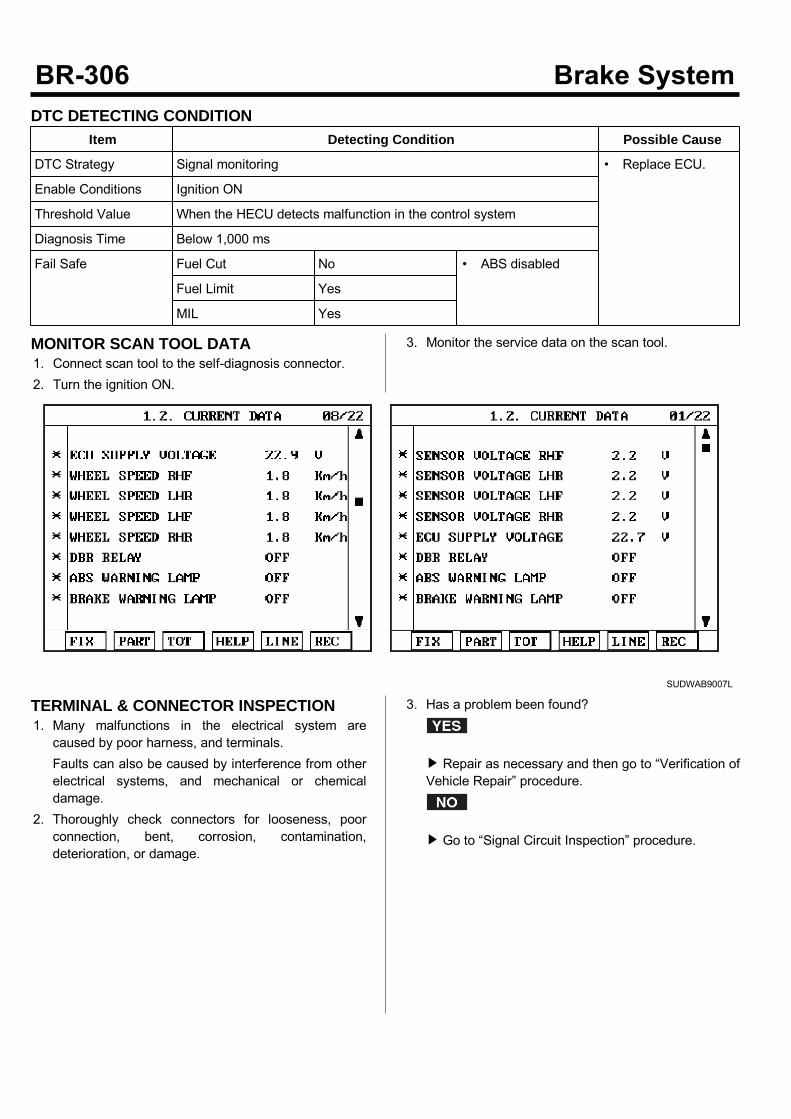
DTC DETECTING CONDITIONItem Detecting Condition Possible Cause
DTC Strategy Signal monitoring • Replace ECU.
Enable Conditions Ignition ON
Threshold Value When the HECU detects malfunction in the control system
Diagnosis Time Below 1,000 ms
Fail Safe Fuel Cut No • ABS disabled
Fuel Limit Yes
MIL Yes
MONITOR SCAN TOOL DATA1. Connect scan tool to the self-diagnosis connector.2. Turn the ignition ON.
3. Monitor the service data on the scan tool.
SUDWAB9007L
TERMINAL & CONNECTOR INSPECTION1. Many malfunctions in the electrical system arecaused by poor harness, and terminals.Faults can also be caused by interference from otherelectrical systems, and mechanical or chemicaldamage.
2. Thoroughly check connectors for looseness, poorconnection, bent, corrosion, contamination,deterioration, or damage.
3. Has a problem been found?
Repair as necessary and then go to “Verification ofVehicle Repair” procedure.
Go to “Signal Circuit Inspection” procedure.

COMPONENT INSPECTION1. Start the engine.2. Drive the vehicle with approx. 15km/h or higher.3. Turn the ignition ON. Leave the engine OFF.4. Connect the scan tool and check the diagnostictrouble codes by using self-diagnosis.
5. Using the scan tool erase the diagnostic troublecodes stored in the HECU.
6. Check that there are any diagnostic trouble codes byusing self-diagnosis with the scan tool.
7. Are any diagnostic trouble codes (DTCs) detected?
Check that the DTCs have disappeared afterreplacing with a known-good HECU. If the problemhas solved, we may guess the HECU is problem.Replace the HECU and go to “Verification of VehicleRepair” procedure.
There may be a defective valve component or atransient trouble due to a past trouble which did noterase the memory of HECU after having repair. Andgo to "Verification of Vehicle Repair” procedure.
VERIFICATION OF VEHICLE REPAIRAfter a repair, it is essential to verify that the fault hasbeen corrected.1. Connect the scan tool and perform the self diagnosis.Check diagnostic trouble codes.
2. Clear the diagnostic trouble codes (DTCs) stored inthe ECM by using the scan tool.
3. Drive the vehicle under conditions noted in failurerecords.
4. Check that there are any DTCs by performing selfdiagnosis with the scan tool.
5. Did the DTC return?
Go to the applicable DTC procedure.
System OK
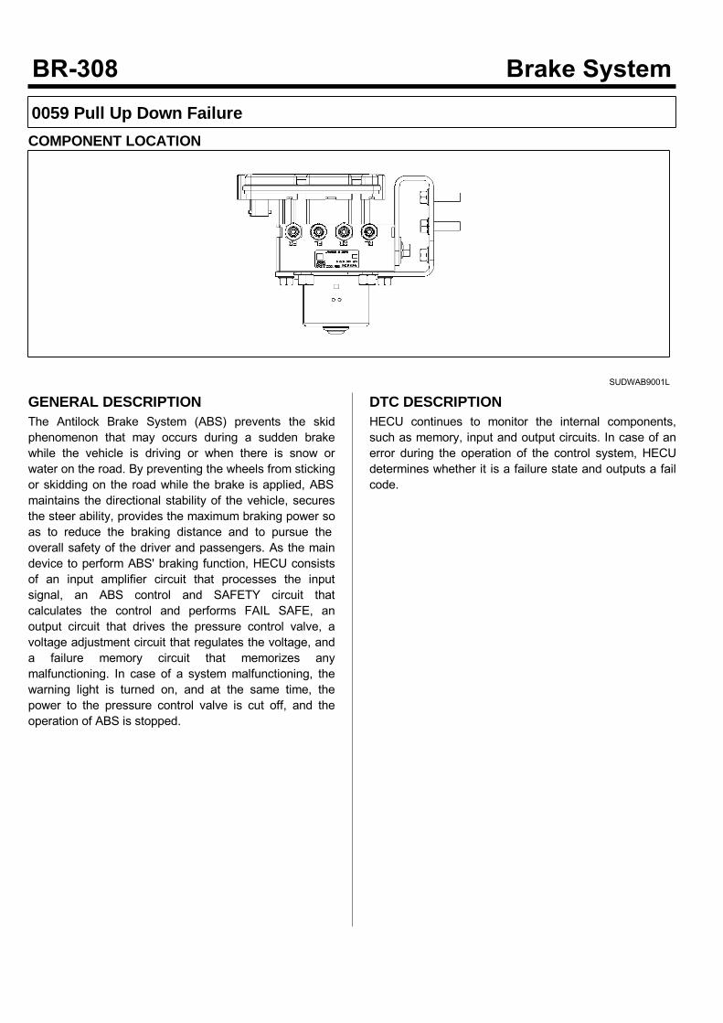
0059 Pull Up Down FailureCOMPONENT LOCATION
SUDWAB9001L
GENERAL DESCRIPTIONThe Antilock Brake System (ABS) prevents the skidphenomenon that may occurs during a sudden brakewhile the vehicle is driving or when there is snow orwater on the road. By preventing the wheels from stickingor skidding on the road while the brake is applied, ABSmaintains the directional stability of the vehicle, securesthe steer ability, provides the maximum braking power soas to reduce the braking distance and to pursue theoverall safety of the driver and passengers. As the maindevice to perform ABS' braking function, HECU consistsof an input amplifier circuit that processes the inputsignal, an ABS control and SAFETY circuit thatcalculates the control and performs FAIL SAFE, anoutput circuit that drives the pressure control valve, avoltage adjustment circuit that regulates the voltage, anda failure memory circuit that memorizes anymalfunctioning. In case of a system malfunctioning, thewarning light is turned on, and at the same time, thepower to the pressure control valve is cut off, and theoperation of ABS is stopped.
DTC DESCRIPTIONHECU continues to monitor the internal components,such as memory, input and output circuits. In case of anerror during the operation of the control system, HECUdetermines whether it is a failure state and outputs a failcode.
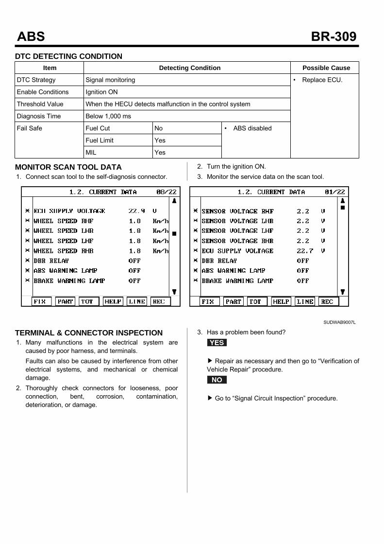
DTC DETECTING CONDITIONItem Detecting Condition Possible Cause
DTC Strategy Signal monitoring • Replace ECU.
Enable Conditions Ignition ON
Threshold Value When the HECU detects malfunction in the control system
Diagnosis Time Below 1,000 ms
Fail Safe Fuel Cut No • ABS disabled
Fuel Limit Yes
MIL Yes
MONITOR SCAN TOOL DATA1. Connect scan tool to the self-diagnosis connector.
2. Turn the ignition ON.3. Monitor the service data on the scan tool.
SUDWAB9007L
TERMINAL & CONNECTOR INSPECTION1. Many malfunctions in the electrical system arecaused by poor harness, and terminals.Faults can also be caused by interference from otherelectrical systems, and mechanical or chemicaldamage.
2. Thoroughly check connectors for looseness, poorconnection, bent, corrosion, contamination,deterioration, or damage.
3. Has a problem been found?
Repair as necessary and then go to “Verification ofVehicle Repair” procedure.
Go to “Signal Circuit Inspection” procedure.
COMPONENT INSPECTION1. Start the engine.2. Drive the vehicle with approx. 15km/h or higher.3. Turn the ignition ON. Leave the engine OFF.4. Connect the scan tool and check the diagnostictrouble codes by using self-diagnosis.
5. Using the scan tool erase the diagnostic troublecodes stored in the HECU.
6. Check that there are any diagnostic trouble codes byusing self-diagnosis with the scan tool.
7. Are any diagnostic trouble codes (DTCs) detected?
Check that the DTCs have disappeared afterreplacing with a known-good HECU. If the problemhas solved, we may guess the HECU is problem.Replace the HECU and go to “Verification of VehicleRepair” procedure.
There may be a defective valve component or atransient trouble due to a past trouble which did noterase the memory of HECU after having repair. Andgo to "Verification of Vehicle Repair” procedure.
VERIFICATION OF VEHICLE REPAIRAfter a repair, it is essential to verify that the fault hasbeen corrected.1. Connect the scan tool and perform the self diagnosis.Check diagnostic trouble codes.
2. Clear the diagnostic trouble codes (DTCs) stored inthe ECM by using the scan tool.
3. Drive the vehicle under conditions noted in failurerecords.
4. Check that there are any DTCs by performing selfdiagnosis with the scan tool.
5. Did the DTC return?
Go to the applicable DTC procedure.
System OK
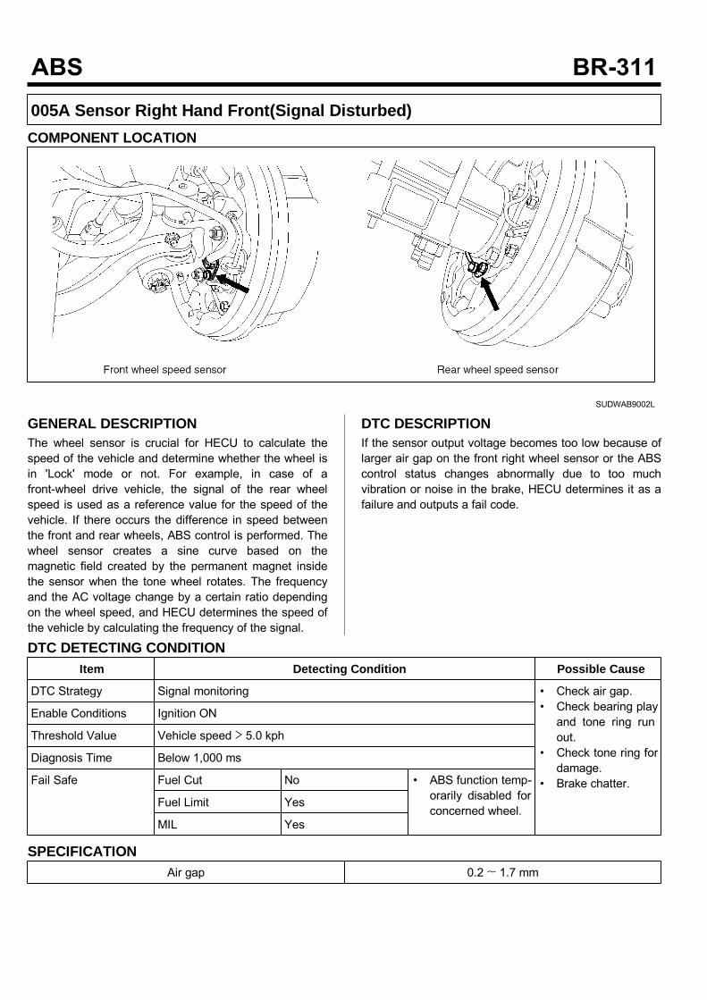
005A Sensor Right Hand Front(Signal Disturbed)COMPONENT LOCATION
SUDWAB9002L
GENERAL DESCRIPTIONThe wheel sensor is crucial for HECU to calculate thespeed of the vehicle and determine whether the wheel isin 'Lock' mode or not. For example, in case of afront-wheel drive vehicle, the signal of the rear wheelspeed is used as a reference value for the speed of thevehicle. If there occurs the difference in speed betweenthe front and rear wheels, ABS control is performed. Thewheel sensor creates a sine curve based on themagnetic field created by the permanent magnet insidethe sensor when the tone wheel rotates. The frequencyand the AC voltage change by a certain ratio dependingon the wheel speed, and HECU determines the speed ofthe vehicle by calculating the frequency of the signal.
DTC DESCRIPTIONIf the sensor output voltage becomes too low because oflarger air gap on the front right wheel sensor or the ABScontrol status changes abnormally due to too muchvibration or noise in the brake, HECU determines it as afailure and outputs a fail code.
DTC DETECTING CONDITIONItem Detecting Condition Possible Cause
DTC Strategy Signal monitoring • Check air gap.• Check bearing playand tone ring runout.
• Check tone ring fordamage.
• Brake chatter.
Enable Conditions Ignition ON
Threshold Value Vehicle speed > 5.0 kph
Diagnosis Time Below 1,000 ms
Fail Safe Fuel Cut No • ABS function temp-orarily disabled forconcerned wheel.
Fuel Limit Yes
MIL Yes
SPECIFICATIONAir gap 0.2 ~ 1.7 mm
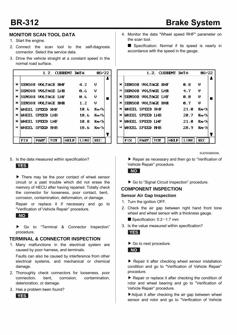
MONITOR SCAN TOOL DATA1. Start the engine.2. Connect the scan tool to the self-diagnosisconnector. Select the service data.
3. Drive the vehicle straight at a constant speed in thenormal road surface.
4. Monitor the data "Wheel speed RHF" parameter onthe scan tool. Specification: Normal if its speed is nearly inaccordance with the speed in the gauge.
SUDWAB9008L
5. Is the data measured within specification?
There may be the poor contact of wheel sensorcircuit or a past trouble which did not erase thememory of HECU after having repaired. Totally checkthe connector for looseness, poor contact, bent,corrosion, contamination, deformation, or damage.Repair or replace it if necessary and go to"Verification of Vehicle Repair” procedure.
Go to “Terminal & Connector Inspection”procedure.
TERMINAL & CONNECTOR INSPECTION1. Many malfunctions in the electrical system arecaused by poor harness, and terminals.Faults can also be caused by interference from otherelectrical systems, and mechanical or chemicaldamage.
2. Thoroughly check connectors for looseness, poorconnection, bent, corrosion, contamination,deterioration, or damage.
3. Has a problem been found?
Repair as necessary and then go to “Verification ofVehicle Repair” procedure.
Go to “Signal Circuit Inspection” procedure.
COMPONENT INSPECTIONSensor Air Gap Inspection1. Turn the ignition OFF.2. Check the air gap between right hand front tonewheel and wheel sensor with a thickness gauge. Specification: 0.2~1.7 mm
3. Is the value measured within specification?
Go to next procedure.
Repair it after checking wheel sensor installationcondition and go to "Verification of Vehicle Repair”procedure. Repair or replace it after checking the condition ofrotor and wheel bearing and go to "Verification ofVehicle Repair” procedure.Adjust it after checking the air gap between wheelsensor and rotor and go to "Verification of Vehicle
Repair” procedure.Check Number of Teeth on Tone Ring1. Turn the ignition OFF.2. Check the number of teeth on right hand front tonering.
3. Is the number of teeth normal?
Go to "Verification of Vehicle Repair” procedure.
Repair it or replace with known-good one andcheck the condition of vehicle. If normal, replace with new one. And go to"Verification of Vehicle Repair” procedure.
Check Brake Chatter1. Turn the ignition OFF.2. Check the pad and drum of the right hand frontbrake.
3. Is the condition of the brake normal?
Go to "Verification of Vehicle Repair” procedure.
Repair it or replace with known-good one andcheck the condition of the vehicle. If normal, replace with new one. And go to"Verification of Vehicle Repair” procedure.
VERIFICATION OF VEHICLE REPAIRAfter a repair, it is essential to verify that the fault hasbeen corrected.1. Connect the scan tool and perform the self diagnosis.Check diagnostic trouble codes.
2. Clear the diagnostic trouble codes (DTCs) stored inthe ECM by using the scan tool.
3. Drive the vehicle under conditions noted in failurerecords.
4. Check that there are any DTCs by performing selfdiagnosis with the scan tool.
5. Did the DTC return?
Go to the applicable DTC procedure.
System OK
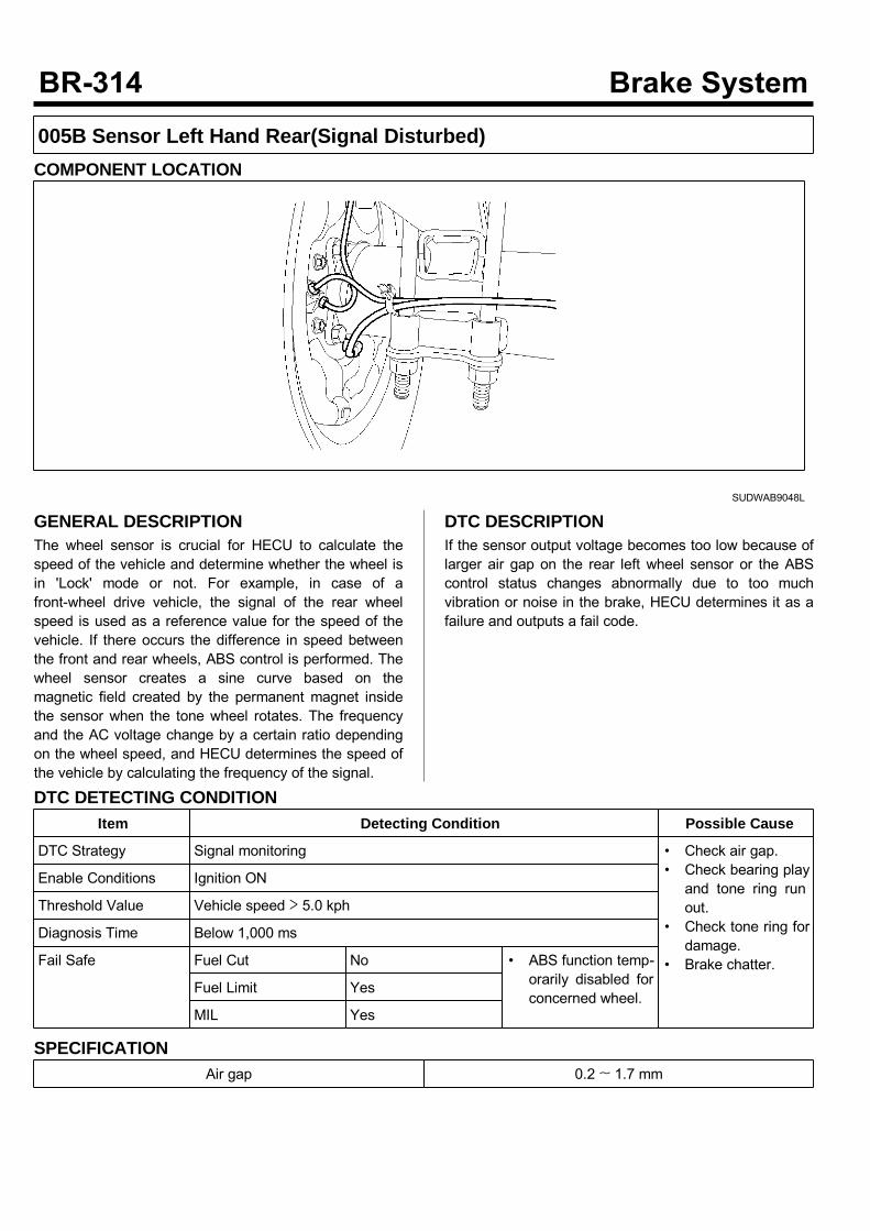
005B Sensor Left Hand Rear(Signal Disturbed)COMPONENT LOCATION
SUDWAB9048L
GENERAL DESCRIPTIONThe wheel sensor is crucial for HECU to calculate thespeed of the vehicle and determine whether the wheel isin 'Lock' mode or not. For example, in case of afront-wheel drive vehicle, the signal of the rear wheelspeed is used as a reference value for the speed of thevehicle. If there occurs the difference in speed betweenthe front and rear wheels, ABS control is performed. Thewheel sensor creates a sine curve based on themagnetic field created by the permanent magnet insidethe sensor when the tone wheel rotates. The frequencyand the AC voltage change by a certain ratio dependingon the wheel speed, and HECU determines the speed ofthe vehicle by calculating the frequency of the signal.
DTC DESCRIPTIONIf the sensor output voltage becomes too low because oflarger air gap on the rear left wheel sensor or the ABScontrol status changes abnormally due to too muchvibration or noise in the brake, HECU determines it as afailure and outputs a fail code.
DTC DETECTING CONDITIONItem Detecting Condition Possible Cause
DTC Strategy Signal monitoring • Check air gap.• Check bearing playand tone ring runout.
• Check tone ring fordamage.
• Brake chatter.
Enable Conditions Ignition ON
Threshold Value Vehicle speed > 5.0 kph
Diagnosis Time Below 1,000 ms
Fail Safe Fuel Cut No • ABS function temp-orarily disabled forconcerned wheel.
Fuel Limit Yes
MIL Yes
SPECIFICATIONAir gap 0.2 ~ 1.7 mm

MONITOR SCAN TOOL DATA1. Start the engine.2. Connect the scan tool to the self-diagnosisconnector. Select the service data.
3. Drive the vehicle straight at a constant speed in thenormal road surface.
4. Monitor the data "Wheel speed LHR" parameter onthe scan tool. Specification: Normal if its speed is nearly inaccordance with the speed in the gauge.
SUDWAB9008L
5. Is the data measured within specification?
There may be the poor contact of wheel sensorcircuit or a past trouble which did not erase thememory of HECU after having repaired. Totally checkthe connector for looseness, poor contact, bent,corrosion, contamination, deformation, or damage. Repair or replace it if necessary and go to"Verification of Vehicle Repair” procedure.
Go to “Terminal & Connector Inspection”procedure.
TERMINAL & CONNECTOR INSPECTION1. Many malfunctions in the electrical system arecaused by poor harness, and terminals.Faults can also be caused by interference from otherelectrical systems, and mechanical or chemicaldamage.
2. Thoroughly check connectors for looseness, poorconnection, bent, corrosion, contamination,deterioration, or damage.
3. Has a problem been found?
Repair as necessary and then go to “Verification ofVehicle Repair” procedure.
Go to “Signal Circuit Inspection” procedure.
COMPONENT INSPECTIONSensor Air Gap Inspection1. Turn the ignition OFF.2. Check the air gap between left hand rear tone wheeland wheel sensor with a thickness gauge. Specification: 0.2~1.7mm
3. Is the value measured within specification?
Go to next procedure.
Repair it after checking wheel sensor installationcondition and go to "Verification of Vehicle Repair”procedure. Repair or replace it after checking the condition ofrotor and wheel bearing and go to "Verification ofVehicle Repair” procedure. Adjust it after checking the air gap between wheelsensor and rotor and go to "Verification of Vehicle

Repair” procedure.Check Number of Teeth on Tone Ring1. Turn the ignition OFF.2. Check the number of teeth on left hand rear tonering.
3. Is the number of teeth normal?
Go to "Verification of Vehicle Repair” procedure.
Repair it or replace with known-good one andcheck the condition of vehicle. If normal, replace with new one. And go to"Verification of Vehicle Repair” procedure.
Check Brake Chatter1. Turn the ignition OFF.2. Check the pad and drum of the left hand rear brake.3. Is the condition of the brake normal?
Go to "Verification of Vehicle Repair” procedure.
Repair it or replace with known-good one andcheck the condition of the vehicle. If normal, replace with new one. And go to"Verification of Vehicle Repair” procedure.
VERIFICATION OF VEHICLE REPAIRAfter a repair, it is essential to verify that the fault hasbeen corrected.1. Connect the scan tool and perform the self diagnosis.Check diagnostic trouble codes.
2. Clear the diagnostic trouble codes (DTCs) stored inthe ECM by using the scan tool.
3. Drive the vehicle under conditions noted in failurerecords.
4. Check that there are any DTCs by performing selfdiagnosis with the scan tool.
5. Did the DTC return?
Go to the applicable DTC procedure.
System OK
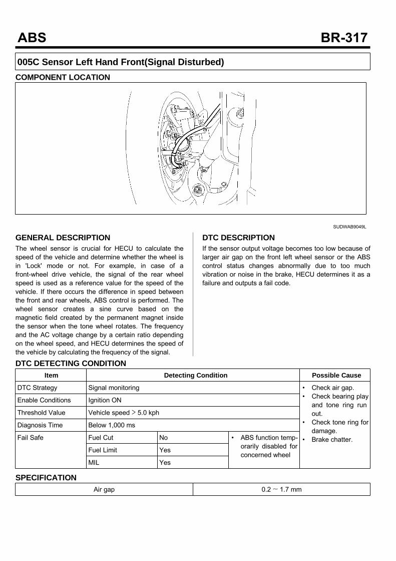
005C Sensor Left Hand Front(Signal Disturbed)COMPONENT LOCATION
SUDWAB9049L
GENERAL DESCRIPTIONThe wheel sensor is crucial for HECU to calculate thespeed of the vehicle and determine whether the wheel isin 'Lock' mode or not. For example, in case of afront-wheel drive vehicle, the signal of the rear wheelspeed is used as a reference value for the speed of thevehicle. If there occurs the difference in speed betweenthe front and rear wheels, ABS control is performed. Thewheel sensor creates a sine curve based on themagnetic field created by the permanent magnet insidethe sensor when the tone wheel rotates. The frequencyand the AC voltage change by a certain ratio dependingon the wheel speed, and HECU determines the speed ofthe vehicle by calculating the frequency of the signal.
DTC DESCRIPTIONIf the sensor output voltage becomes too low because oflarger air gap on the front left wheel sensor or the ABScontrol status changes abnormally due to too muchvibration or noise in the brake, HECU determines it as afailure and outputs a fail code.
DTC DETECTING CONDITIONItem Detecting Condition Possible Cause
DTC Strategy Signal monitoring • Check air gap.• Check bearing playand tone ring runout.
• Check tone ring fordamage.
• Brake chatter.
Enable Conditions Ignition ON
Threshold Value Vehicle speed > 5.0 kph
Diagnosis Time Below 1,000 ms
Fail Safe Fuel Cut No • ABS function temp-orarily disabled forconcerned wheel
Fuel Limit Yes
MIL Yes
SPECIFICATIONAir gap 0.2 ~ 1.7 mm

MONITOR SCAN TOOL DATA1. Start the engine.2. Connect the scan tool to the self-diagnosisconnector. Select the service data.
3. Drive the vehicle straight at a constant speed in thenormal road surface.
4. Monitor the data "Wheel speed LHF" parameter onthe scan tool. Specification: Normal if its speed is nearly inaccordance with the speed in the gauge.
SUDWAB9008L
5. Is the data measured within specification?
There may be the poor contact of wheel sensorcircuit or a past trouble which did not erase thememory of HECU after having repaired. Totally checkthe connector for looseness, poor contact, bent,corrosion, contamination, deformation, or damage. Repair or replace it if necessary and go to"Verification of Vehicle Repair” procedure.
Go to “Terminal & Connector Inspection”procedure.
TERMINAL & CONNECTOR INSPECTION1. Many malfunctions in the electrical system arecaused by poor harness, and terminals.Faults can also be caused by interference from otherelectrical systems, and mechanical or chemicaldamage.
2. Thoroughly check connectors for looseness, poorconnection, bent, corrosion, contamination,deterioration, or damage.
3. Has a problem been found?
Repair as necessary and then go to “Verification ofVehicle Repair” procedure.
Go to “Signal Circuit Inspection” procedure.
COMPONENT INSPECTIONSensor Air Gap Inspection1. Turn the ignition OFF.2. Check the air gap between left hand front tone wheeland wheel sensor with a thickness gauge. Specification: 0.2~1.7 mm
3. Is the value measured within specification?
Go to next procedure.
Repair it after checking wheel sensor installationcondition and go to "Verification of Vehicle Repair”procedure. Repair or replace it after checking the condition ofrotor and wheel bearing and go to "Verification ofVehicle Repair” procedure. Adjust it after checking the air gap between wheelsensor and rotor and go to "Verification of Vehicle
Repair” procedure.Check Number of Teeth on Tone Ring1. Turn the ignition OFF.2. Check the number of teeth on left hand front tonering.
3. Is the number of teeth normal?
Go to "Verification of Vehicle Repair” procedure.
Repair it or replace with known-good one andcheck the condition of vehicle. If normal, replace with new one. And go to"Verification of Vehicle Repair” procedure.
Check Brake Chatter1. Turn the ignition OFF.2. Check the pad and drum of the left hand front brake.3. Is the condition of the brake normal?
Go to "Verification of Vehicle Repair” procedure.
Repair it or replace with known-good one andcheck the condition of the vehicle. If normal, replace with new one. And go to"Verification of Vehicle Repair” procedure.
VERIFICATION OF VEHICLE REPAIRAfter a repair, it is essential to verify that the fault hasbeen corrected.1. Connect the scan tool and perform the self diagnosis.Check diagnostic trouble codes.
2. Clear the diagnostic trouble codes (DTCs) stored inthe ECM by using the scan tool.
3. Drive the vehicle under conditions noted in failurerecords.
4. Check that there are any DTCs by performing selfdiagnosis with the scan tool.
5. Did the DTC return?
Go to the applicable DTC procedure.
System OK

005D Sensor Right Hand Rear(Signal Disturbed)COMPONENT LOCATION
SUDWAB9050L
GENERAL DESCRIPTIONThe wheel sensor is crucial for HECU to calculate thespeed of the vehicle and determine whether the wheel isin 'Lock' mode or not. For example, in case of afront-wheel drive vehicle, the signal of the rear wheelspeed is used as a reference value for the speed of thevehicle. If there occurs the difference in speed betweenthe front and rear wheels, ABS control is performed. Thewheel sensor creates a sine curve based on themagnetic field created by the permanent magnet insidethe sensor when the tone wheel rotates. The frequencyand the AC voltage change by a certain ratio dependingon the wheel speed, and HECU determines the speed ofthe vehicle by calculating the frequency of the signal.
DTC DESCRIPTIONIf the sensor output voltage becomes too low because oflarger air gap on the rear right wheel sensor or the ABScontrol status changes abnormally due to too muchvibration or noise in the brake, HECU determines it as afailure and outputs a fail code.
DTC DETECTING CONDITIONItem Detecting Condition Possible Cause
DTC Strategy Signal monitoring • Check air gap.• Check bearing playand tone ring runout.
• Check tone ring fordamage.
• Brake chatter.
Enable Conditions Ignition ON
Threshold Value .Vehicle speed > 5.0 kph
Diagnosis Time Below 1,000 ms
Fail Safe Fuel Cut No • ABS function temp-orarily disabled forconcerned wheel.
Fuel Limit Yes
MIL Yes
SPECIFICATIONAir gap 0.2 ~ 1.7 mm
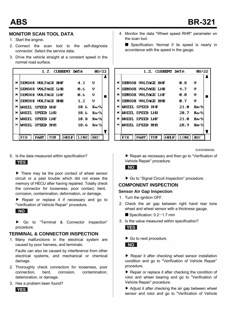
MONITOR SCAN TOOL DATA1. Start the engine.2. Connect the scan tool to the self-diagnosisconnector. Select the service data.
3. Drive the vehicle straight at a constant speed in thenormal road surface.
4. Monitor the data "Wheel speed RHR" parameter onthe scan tool. Specification: Normal if its speed is nearly inaccordance with the speed in the gauge.
SUDWAB9008L
5. Is the data measured within specification?
There may be the poor contact of wheel sensorcircuit or a past trouble which did not erase thememory of HECU after having repaired. Totally checkthe connector for looseness, poor contact, bent,corrosion, contamination, deformation, or damage. Repair or replace it if necessary and go to"Verification of Vehicle Repair” procedure.
Go to “Terminal & Connector Inspection”procedure.
TERMINAL & CONNECTOR INSPECTION1. Many malfunctions in the electrical system arecaused by poor harness, and terminals.Faults can also be caused by interference from otherelectrical systems, and mechanical or chemicaldamage.
2. Thoroughly check connectors for looseness, poorconnection, bent, corrosion, contamination,deterioration, or damage.
3. Has a problem been found?
Repair as necessary and then go to “Verification ofVehicle Repair” procedure.
Go to “Signal Circuit Inspection” procedure.
COMPONENT INSPECTIONSensor Air Gap Inspection1. Turn the ignition OFF.2. Check the air gap between right hand rear tonewheel and wheel sensor with a thickness gauge. Specification: 0.2~1.7 mm
3. Is the value measured within specification?
Go to next procedure.
Repair it after checking wheel sensor installationcondition and go to "Verification of Vehicle Repair”procedure. Repair or replace it after checking the condition ofrotor and wheel bearing and go to "Verification ofVehicle Repair” procedure. Adjust it after checking the air gap between wheelsensor and rotor and go to "Verification of Vehicle
Repair” procedure.Check Number of Teeth on Tone Ring1. Turn the ignition OFF.2. Check the number of teeth on right hand rear tonering.
3. Is the number of teeth normal?
Go to "Verification of Vehicle Repair” procedure.
Repair it or replace with known-good one andcheck the condition of vehicle. If normal, replace with new one. And go to"Verification of Vehicle Repair” procedure.
Check Brake Chatter1. Turn the ignition OFF.2. Check the pad and drum of the right hand rear brake.3. Is the condition of the brake normal?
Go to "Verification of Vehicle Repair” procedure.
Repair it or replace with known-good one andcheck the condition of the vehicle. If normal, replace with new one. And go to"Verification of Vehicle Repair” procedure.
VERIFICATION OF VEHICLE REPAIRAfter a repair, it is essential to verify that the fault hasbeen corrected.1. Connect the scan tool and perform the self diagnosis.Check diagnostic trouble codes.
2. Clear the diagnostic trouble codes (DTCs) stored inthe ECM by using the scan tool.
3. Drive the vehicle under conditions noted in failurerecords.
4. Check that there are any DTCs by performing selfdiagnosis with the scan tool.
5. Did the DTC return?
Go to the applicable DTC procedure.
System OK