Hysteretic performance of a new blind bolted connection to...
26
This is a repository copy of Hysteretic performance of a new blind bolted connection to concrete filled columns under cyclic loading: An experimental investigation . White Rose Research Online URL for this paper: http://eprints.whiterose.ac.uk/85513/ Version: Accepted Version Article: Tizani, W., Wang, Z.Y. and Hajirasouliha, I. (2012) Hysteretic performance of a new blind bolted connection to concrete filled columns under cyclic loading: An experimental investigation. Engineering Structures, 46. 535 - 546. ISSN 0141-0296 https://doi.org/10.1016/j.engstruct.2012.08.020 [email protected] https://eprints.whiterose.ac.uk/ Reuse Unless indicated otherwise, fulltext items are protected by copyright with all rights reserved. The copyright exception in section 29 of the Copyright, Designs and Patents Act 1988 allows the making of a single copy solely for the purpose of non-commercial research or private study within the limits of fair dealing. The publisher or other rights-holder may allow further reproduction and re-use of this version - refer to the White Rose Research Online record for this item. Where records identify the publisher as the copyright holder, users can verify any specific terms of use on the publisher’s website. Takedown If you consider content in White Rose Research Online to be in breach of UK law, please notify us by emailing [email protected] including the URL of the record and the reason for the withdrawal request.
Transcript of Hysteretic performance of a new blind bolted connection to...
This is a repository copy of Hysteretic performance of a new blind bolted connection to concrete filled columns under cyclic loading: An experimental investigation.
White Rose Research Online URL for this paper:http://eprints.whiterose.ac.uk/85513/
Version: Accepted Version
Article:
Tizani, W., Wang, Z.Y. and Hajirasouliha, I. (2012) Hysteretic performance of a new blind bolted connection to concrete filled columns under cyclic loading: An experimental investigation. Engineering Structures, 46. 535 - 546. ISSN 0141-0296
https://doi.org/10.1016/j.engstruct.2012.08.020
[email protected]://eprints.whiterose.ac.uk/
Reuse
Unless indicated otherwise, fulltext items are protected by copyright with all rights reserved. The copyright exception in section 29 of the Copyright, Designs and Patents Act 1988 allows the making of a single copy solely for the purpose of non-commercial research or private study within the limits of fair dealing. The publisher or other rights-holder may allow further reproduction and re-use of this version - refer to the White Rose Research Online record for this item. Where records identify the publisher as the copyright holder, users can verify any specific terms of use on the publisher’s website.
Takedown
If you consider content in White Rose Research Online to be in breach of UK law, please notify us by emailing [email protected] including the URL of the record and the reason for the withdrawal request.
Tizani W, Wang ZY & Hajirasouliha I (2013) Hysteretic performance of a new blind bolted connection to concrete
filled columns under cyclic loading: An experimental investigation. Engineering Structures, 46, 535-546.
Hysteretic Performance of a New Blind Bolted Connection to Concrete
Filled Columns under Cyclic Loading: An Experimental Investigation
Walid Tizani*, Zhi Yu Wang and Iman Hajirasouliha
Department of Civil Engineering, The University of Nottingham, Nottingham, UK
* Corresponding author: [email protected]
ABSTRACT
The structural performance and reliability of a new blind-bolting technique is investigated in this study.
The new blind-bolt is termed Extended Hollobolt (EHB) and is a modification of the standard Hollobolt. The
EHB enhances the tensile resistance and stiffness of the fastener by anchoring it in the concrete infill of a
tubular column. This paper reports on an investigation into the cyclic behaviour of end-plate connections to
concrete filled tubular (CFT) columns using the EHB. A series of six full-scale connections were tested
under quasi-static cyclic loading. The key parameters investigated were amplitude of cyclic loading
procedure, bolt grade, tube wall thickness, and concrete grade. The strength, stiffness, rotation capacity and
energy dissipation capacity of the connections were evaluated at different load cycles. In general, the EHB
provided stable hysteretic behaviour with appropriate level of strength and stiffness. The influence of tube
wall thickness and concrete grade on the strength, stiffness and failure mode of the connections is
investigated. It is shown that sufficient performance can be achieved by controlling the tube wall thickness
and concrete strength. The results indicate that the connection can offer energy dissipation capacity and
ductility appropriate for its potential use in seismic design.
Keywords: Endplate connections; Blind bolts; Concrete filled tubes; Cyclic behaviour
1 INTRODUCTION
The advantages obtained by using concrete-filled tubes (CFT) in multi-storey construction have been
recognised for a number of years [1]. Tubular sections are more efficient than open sections when dealing
with compression, and their load carrying capacity can be significantly increased when filled with concrete.
Moreover, the ductility and rotation capacity of the CFT columns is much enhanced when compared with
1
Tizani W, Wang ZY & Hajirasouliha I (2013) Hysteretic performance of a new blind bolted connection to concrete
filled columns under cyclic loading: An experimental investigation. Engineering Structures, 46, 535-546. other types of composite columns, as the infill concrete is confined and cannot split away even if its ultimate
strength is reached [2]. As a result, CFT columns are very attractive for seismic design of moment resisting
frames in seismic zones. The connection to CFT columns, however, tends to be complicated and would
normally involve welding [3] or the use of embedded steel bars [4] to develop sufficient moment capacity.
The post-earthquake survey conducted following the Northridge earthquake 1994 indicated poor
performance of welded beam to column connections, as they led to brittle fractures and catastrophic failures
in steel structures [5]. As an alternative solution, some improved connection configurations have been
suggested by contemporary researchers, such as bolted endplate connections, which is popular in Europe.
This type of connection is also favoured since it involves shop welding and on-site bolting, thus avoids
issues related to site welding. This type of connection is also available for tubular sections through the use of
blind bolts (such as Hollbolt and Flowdrill), but only as simple pin connections resisting shear loads and
some tension mainly to satisfy the integrity criterion [2]. Blind bolts are bolts that are only tightened from
one side (more details are available from [6]).
Moment-resisting blind-bolted connections to hollow columns are not currently available in practice.
However, a number of research studies have been conducted to determine the resistance of such systems
mainly for typical connections (such as those using Hollbolt, Flowdrill Ajax One-side). Examples of these
studies include work done to evaluate the tensile strength and stiffness of blind-bolt fasteners using T-stub
models [1-9] and full scale endplate connections to CFT columns [10] and others experimental connections
types [11, 12]. France et al [13] conducted monotonic loading tests on Flowdrill connections to CFT
columns, and showed that the strength and stiffness of such connections are dramatically higher than those
without concrete infill. Loh et al. [14] tested cruciform composite blind bolted endplate connections to CFT
column under bending. They reported that using CFT prevents local tube failures. In contrast, hollow steel
would typically fail by excessive deformation of tube face and pull out of the Hollobolts. Goldsworthy et al.
[15] conducted tests on blind bolted T-stub connections. They used a modified Ajax one-side blind bolt. The
modification involved welding a piece of steel reinforcing bar to the end of the bolt shank that was anchored
in the concrete infill. Good results regarding failure modes and capacities were reported except for
unexpected fractures in welds which occurred at the extension bars in some tests. In another study, Wang et
al [16] performed monotonic and cyclic loading tests on eight cruciform bolted endplate connections with
2
Tizani W, Wang ZY & Hajirasouliha I (2013) Hysteretic performance of a new blind bolted connection to concrete
filled columns under cyclic loading: An experimental investigation. Engineering Structures, 46, 535-546. Hollobolts. They used cold-formed tubes, which have affected the failure mode of the tubes from face
bending to splitting at the corners (a typical failure mode for cold-formed tubes).
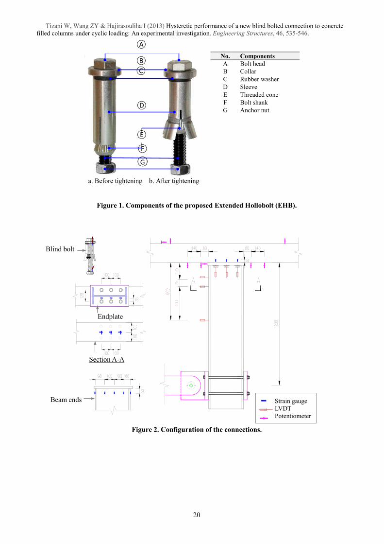
Tizani and Ridley-Ellis [9] performed investigation using a modified Hollobolt, called the Extended
Hollobolt (EHB). In the EHB an extended bolt shank is used with an additional nut (called the anchor nut) as
shown in Figure 1. The extended shank is immersed in the concrete infill and thus can provide an enhanced
blind-bolt tensile strength and stiffness. This technique has proved to be very beneficial as the tensile failure
mode of the EHB resembles that of the standard bolt-nut fastener (i.e the ultimate tensile resistance of the
bolt shank is achieved through bolt shank fracture. This is compared with the typical failure mode of the
standard Hollobolt, which is the pulling out of the connected tube by either the shear failure of its sleeve or
the punching shear of the tube. This latter failure mode tends to occur at a lower resistance level compared to
the ultimate resistance of the bolt shank.
Recent design guidelines, such as FEMA-350 [17] and Eurocode-8 [18], have incorporated the use of
semi-rigid and/or partial strength connections. The performance of moment-resisting (semi-rigid to rigid)
blind-bolted connections under cyclic loading has been investigated for top and bottom cleat connections
made with Hollobolts [19] and for endplate connections to circular hollow sections using Ajax One-side
blind bolts [15]. In these studies, the influences of relevant material and geometric parameters on the cyclic
behaviour of the connections were examined.
Al-Mughairi et al. [10] reported significant improvement in the stiffness of endplate connections made
with the EHB under monotonic loading where the connections exhibited rigid or semi-rigid behaviour. This
outcome was encouraging for this type of connection. However, the performance of this type of blind-bolted
connection under cyclic loading has not yet been examined.
The work presented in this paper attempts to address this issue by investigating the inelastic hysteretic
behaviour of the new proposed blind-bolted connection. The expected response of such connection is more
complex than those not involving concrete infill. This is due to the unknown contribution of the EHB
anchorage in the concrete under cyclic loading. The current study involves conducting representative
experimental programme to examine the contribution of the EHB, the confined concrete and the column
face. Based on the experimental results, the cyclic characteristics of the blind-bolted connection using the
EHB are presented and discussed in terms of failure modes, strength, stiffness, and energy dissipation.
3
Tizani W, Wang ZY & Hajirasouliha I (2013) Hysteretic performance of a new blind bolted connection to concrete
filled columns under cyclic loading: An experimental investigation. Engineering Structures, 46, 535-546.
2 EXPERIMENTAL PROGRAMME
2.1 Test Specimens
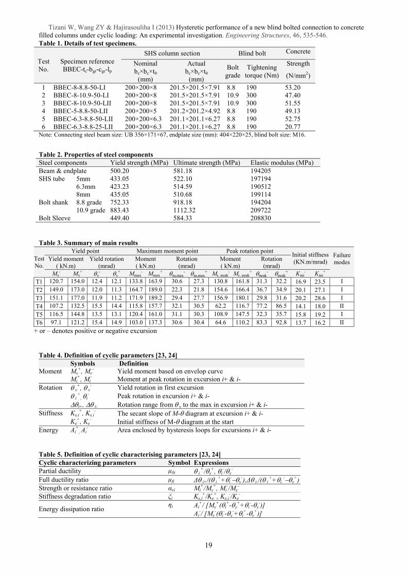
To study the hysteretic behaviour of the blind-bolted connections to CFT using the EHB, six full-scale
beam to column connections have been tested under quasi-static cyclic loading. The connection detailing and
the test arrangements are shown in Figure 2 and Figure 3, respectively. The following parameters were
varied in the test specimens: tube wall thickness (tc), blind bolt grade (bgr), Concrete grade (cgr), and
loading procedure (lp) (see Table 1). The specimens were designated as BBEC-tc-bgr-cgr-lp, where BBEC
denotes blind-bolted-endplate-connection. For instance, the reference for Test 4 in Table 1, BBEC-5-8.8-50-
LII, stands for a tested specimen using 5 mm thick tube, 8.8 blind bolt grade, and with nominal concrete
strength of 50N/mm2, tested using cyclic loading procedure type II. The applied quasi-static cyclic loadings
(type I and II) will be introduced in the next section. All test specimens were designed with similar
configurations of steel beam (UB356×171×67 mm), endplate (404×220×25 mm) and 3 rows of bolts as
shown in Figure 2. This configuration was determined to provide sufficient capacity and stiffness of the
beam and endplate, thereby eliminating their influence on the joint failure mechanism. The design of the test
specimens is outlined as follows: tests T1 and T2 to study the influence of bolt grade; tests T2 and T3 to
study the influence of cyclic loading procedure; tests T1, T4 and T5 to study the influence of tube wall
thickness; and tests T5 and T6 to study the influence of concrete strength.
The blind bolts used in the tests were 16mm diameter (M16) with extended shank length and an end
anchor nut (Figure 1). The blind bolts were initially tightened with a spanner and then with a torque wrench
in accordance to the specified torque values listed in Table 1. Prior to concrete casting and vibration, the
anchor nut was prevented from unexpected rotation and removal by securing it using special glue. Standard
concrete cubes were cast at the same time as the test specimens and cured in water at room temperature of
approximately 20°C. The compressive strengths of the concrete cubes at the time of testing are summarized
in Table 1. The material properties of the steel components are shown in Table 2. These values were
obtained using tensile coupons designed and tested according to EN 10002-1: 2001 [20].
4
Tizani W, Wang ZY & Hajirasouliha I (2013) Hysteretic performance of a new blind bolted connection to concrete
filled columns under cyclic loading: An experimental investigation. Engineering Structures, 46, 535-546.
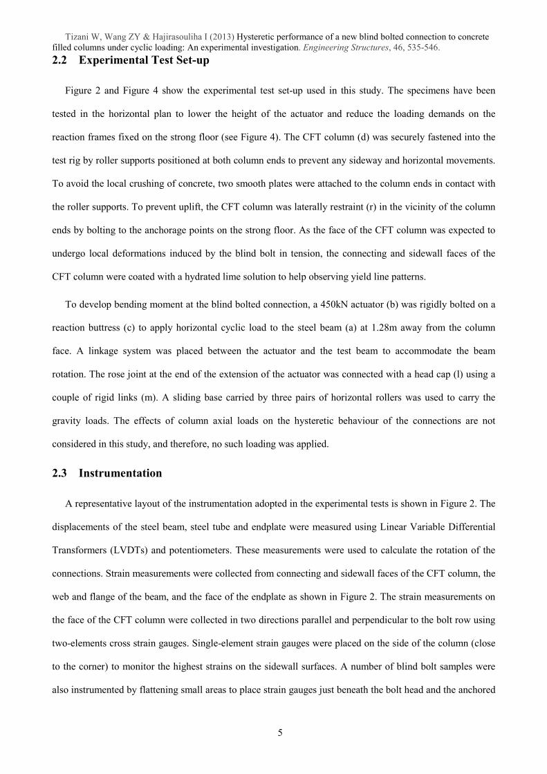
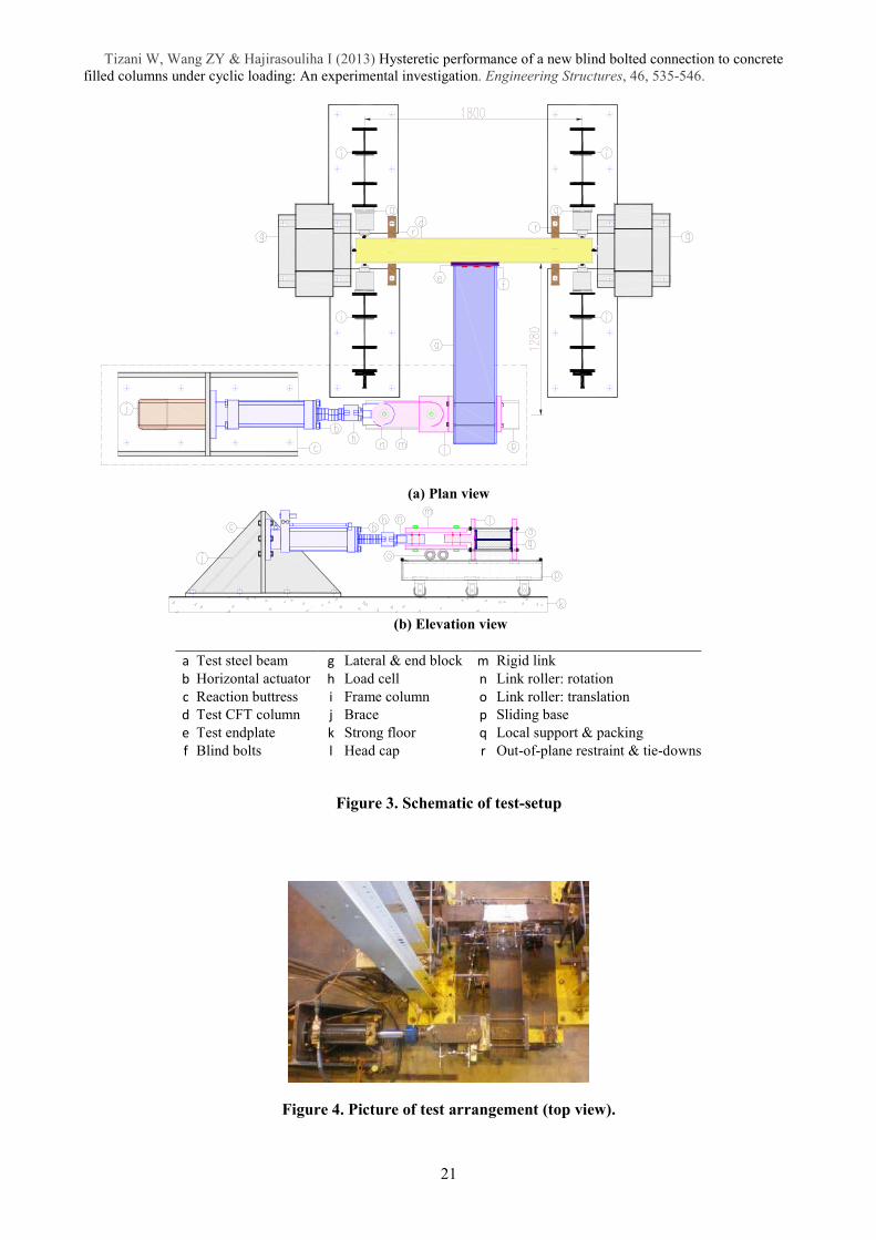
2.2 Experimental Test Set-up
Figure 2 and Figure 4 show the experimental test set-up used in this study. The specimens have been
tested in the horizontal plan to lower the height of the actuator and reduce the loading demands on the
reaction frames fixed on the strong floor (see Figure 4). The CFT column (d) was securely fastened into the
test rig by roller supports positioned at both column ends to prevent any sideway and horizontal movements.
To avoid the local crushing of concrete, two smooth plates were attached to the column ends in contact with
the roller supports. To prevent uplift, the CFT column was laterally restraint (r) in the vicinity of the column
ends by bolting to the anchorage points on the strong floor. As the face of the CFT column was expected to
undergo local deformations induced by the blind bolt in tension, the connecting and sidewall faces of the
CFT column were coated with a hydrated lime solution to help observing yield line patterns.
To develop bending moment at the blind bolted connection, a 450kN actuator (b) was rigidly bolted on a
reaction buttress (c) to apply horizontal cyclic load to the steel beam (a) at 1.28m away from the column
face. A linkage system was placed between the actuator and the test beam to accommodate the beam
rotation. The rose joint at the end of the extension of the actuator was connected with a head cap (l) using a
couple of rigid links (m). A sliding base carried by three pairs of horizontal rollers was used to carry the
gravity loads. The effects of column axial loads on the hysteretic behaviour of the connections are not
considered in this study, and therefore, no such loading was applied.
2.3 Instrumentation
A representative layout of the instrumentation adopted in the experimental tests is shown in Figure 2. The
displacements of the steel beam, steel tube and endplate were measured using Linear Variable Differential
Transformers (LVDTs) and potentiometers. These measurements were used to calculate the rotation of the
connections. Strain measurements were collected from connecting and sidewall faces of the CFT column, the
web and flange of the beam, and the face of the endplate as shown in Figure 2. The strain measurements on
the face of the CFT column were collected in two directions parallel and perpendicular to the bolt row using
two-elements cross strain gauges. Single-element strain gauges were placed on the side of the column (close
to the corner) to monitor the highest strains on the sidewall surfaces. A number of blind bolt samples were
also instrumented by flattening small areas to place strain gauges just beneath the bolt head and the anchored
5
Tizani W, Wang ZY & Hajirasouliha I (2013) Hysteretic performance of a new blind bolted connection to concrete
filled columns under cyclic loading: An experimental investigation. Engineering Structures, 46, 535-546. nut. These instrumented bolts were considered to have reduced strength, and therefore, have been placed in
the middle bolt row of the connection to avoid most highly loaded positions.
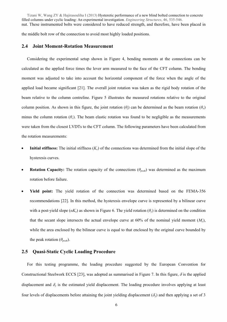
2.4 Joint Moment-Rotation Measurement
Considering the experimental setup shown in Figure 4, bending moments at the connections can be
calculated as the applied force times the lever arm measured to the face of the CFT column. The bending
moment was adjusted to take into account the horizontal component of the force when the angle of the
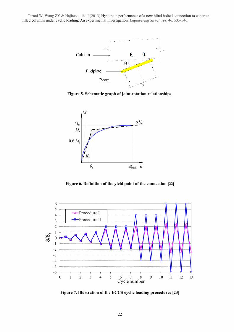
applied load became significant [21]. The overall joint rotation was taken as the rigid body rotation of the
beam relative to the column centreline. Figure 5 illustrates the measured rotations relative to the original
column position. As shown in this figure, the joint rotation (șj) can be determined as the beam rotation (șo)
minus the column rotation (șc). The beam elastic rotation was found to be negligible as the measurements
were taken from the closest LVDTs to the CFT column. The following parameters have been calculated from
the rotation measurements:
• Initial stiffness: The initial stiffness (Ke) of the connections was determined from the initial slope of the
hysteresis curves.
• Rotation Capacity: The rotation capacity of the connections (șpeak) was determined as the maximum
rotation before failure.
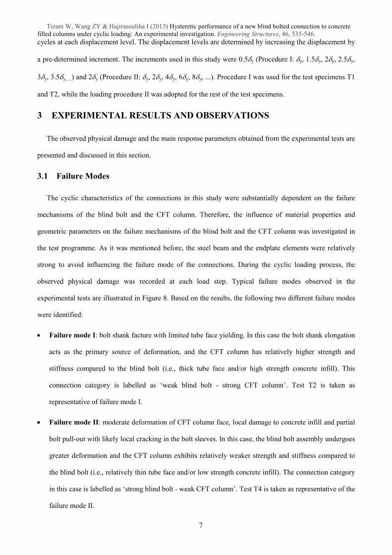
• Yield point: The yield rotation of the connection was determined based on the FEMA-356
recommendations [22]. In this method, the hysteresis envelope curve is represented by a bilinear curve
with a post-yield slope (ĮKe) as shown in Figure 6. The yield rotation (șy) is determined on the condition
that the secant slope intersects the actual envelope curve at 60% of the nominal yield moment (My),
while the area enclosed by the bilinear curve is equal to that enclosed by the original curve bounded by
the peak rotation (șpeak).
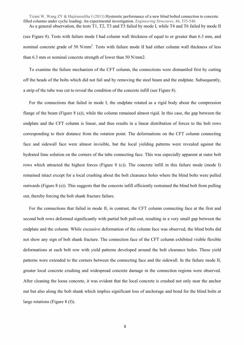
2.5 Quasi-Static Cyclic Loading Procedure
For this testing programme, the loading procedure suggested by the European Convention for
Constructional Steelwork ECCS [23], was adopted as summarised in Figure 7. In this figure, δ is the applied
displacement and δy is the estimated yield displacement. The loading procedure involves applying at least
four levels of displacements before attaining the joint yielding displacement (δy) and then applying a set of 3
6
Tizani W, Wang ZY & Hajirasouliha I (2013) Hysteretic performance of a new blind bolted connection to concrete
filled columns under cyclic loading: An experimental investigation. Engineering Structures, 46, 535-546. cycles at each displacement level. The displacement levels are determined by increasing the displacement by
a pre-determined increment. The increments used in this study were 0.5δy (Procedure I: δy, 1.5δy, 2δy, 2.5δy,
3δy, 3.5δy, ...) and 2δy (Procedure II: δy, 2δy, 4δy, 6δy, 8δy, ...). Procedure I was used for the test specimens T1
and T2, while the loading procedure II was adopted for the rest of the test specimens.
3 EXPERIMENTAL RESULTS AND OBSERVATIONS
The observed physical damage and the main response parameters obtained from the experimental tests are
presented and discussed in this section.
3.1 Failure Modes
The cyclic characteristics of the connections in this study were substantially dependent on the failure
mechanisms of the blind bolt and the CFT column. Therefore, the influence of material properties and
geometric parameters on the failure mechanisms of the blind bolt and the CFT column was investigated in
the test programme. As it was mentioned before, the steel beam and the endplate elements were relatively
strong to avoid influencing the failure mode of the connections. During the cyclic loading process, the
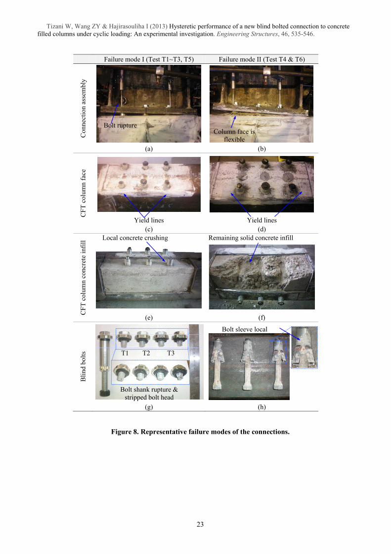
observed physical damage was recorded at each load step. Typical failure modes observed in the
experimental tests are illustrated in Figure 8. Based on the results, the following two different failure modes
were identified:
• Failure mode I: bolt shank facture with limited tube face yielding. In this case the bolt shank elongation
acts as the primary source of deformation, and the CFT column has relatively higher strength and
stiffness compared to the blind bolt (i.e., thick tube face and/or high strength concrete infill). This
connection category is labelled as �weak blind bolt - strong CFT column�. Test T2 is taken as
representative of failure mode I.
• Failure mode II: moderate deformation of CFT column face, local damage to concrete infill and partial
bolt pull-out with likely local cracking in the bolt sleeves. In this case, the blind bolt assembly undergoes
greater deformation and the CFT column exhibits relatively weaker strength and stiffness compared to
the blind bolt (i.e., relatively thin tube face and/or low strength concrete infill). The connection category
in this case is labelled as �strong blind bolt - weak CFT column�. Test T4 is taken as representative of the
failure mode II.
7
Tizani W, Wang ZY & Hajirasouliha I (2013) Hysteretic performance of a new blind bolted connection to concrete
filled columns under cyclic loading: An experimental investigation. Engineering Structures, 46, 535-546. As a general observation, the tests T1, T2, T3 and T5 failed by mode I, while T4 and T6 failed by mode II
(see Figure 8). Tests with failure mode I had column wall thickness of equal to or greater than 6.3 mm, and
nominal concrete grade of 50 N/mm2. Tests with failure mode II had either column wall thickness of less
than 6.3 mm or nominal concrete strength of lower than 50 N/mm2.
To examine the failure mechanism of the CFT column, the connections were dismantled first by cutting
off the heads of the bolts which did not fail and by removing the steel beam and the endplate. Subsequently,
a strip of the tube was cut to reveal the condition of the concrete infill (see Figure 8).
For the connections that failed in mode I, the endplate rotated as a rigid body about the compression
flange of the beam (Figure 8 (a)), while the column remained almost rigid. In this case, the gap between the
endplate and the CFT column is linear, and thus results in a linear distribution of forces to the bolt rows
corresponding to their distance from the rotation point. The deformations on the CFT column connecting
face and sidewall face were almost invisible, but the local yielding patterns were revealed against the
hydrated lime solution on the corners of the tube connecting face. This was especially apparent at outer bolt
rows which attracted the highest forces (Figure 8 (c)). The concrete infill in this failure mode (mode I)
remained intact except for a local crushing about the bolt clearance holes where the blind bolts were pulled
outwards (Figure 8 (e)). This suggests that the concrete infill efficiently restrained the blind bolt from pulling
out, thereby forcing the bolt shank fracture failure.
For the connections that failed in mode II, in contrast, the CFT column connecting face at the first and
second bolt rows deformed significantly with partial bolt pull-out, resulting in a very small gap between the
endplate and the column. While excessive deformation of the column face was observed, the blind bolts did
not show any sign of bolt shank fracture. The connection face of the CFT column exhibited visible flexible
deformations at each bolt row with yield patterns developed around the bolt clearance holes. These yield
patterns were extended to the corners between the connecting face and the sidewall. In the failure mode II,
greater local concrete crushing and widespread concrete damage in the connection regions were observed.
After cleaning the loose concrete, it was evident that the local concrete is crushed not only near the anchor
nut but also along the bolt shank which implies significant loss of anchorage and bond for the blind bolts at
large rotations (Figure 8 (f)).
8
Tizani W, Wang ZY & Hajirasouliha I (2013) Hysteretic performance of a new blind bolted connection to concrete
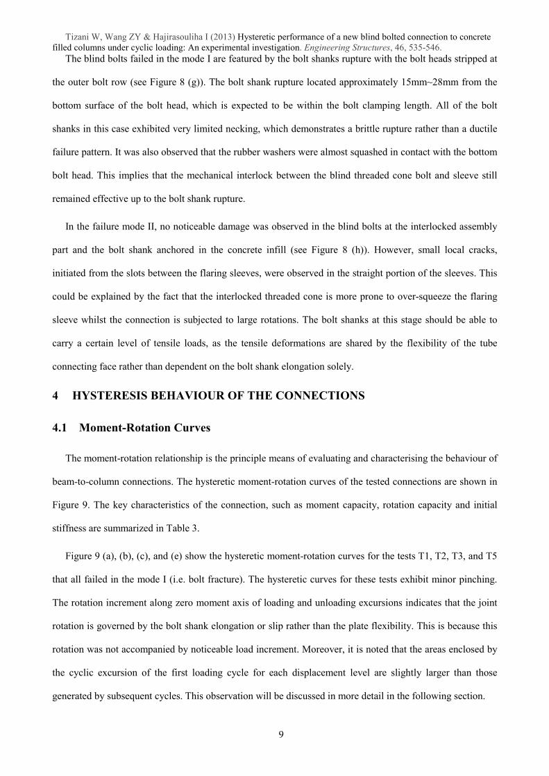
filled columns under cyclic loading: An experimental investigation. Engineering Structures, 46, 535-546. The blind bolts failed in the mode I are featured by the bolt shanks rupture with the bolt heads stripped at
the outer bolt row (see Figure 8 (g)). The bolt shank rupture located approximately 15mm~28mm from the
bottom surface of the bolt head, which is expected to be within the bolt clamping length. All of the bolt
shanks in this case exhibited very limited necking, which demonstrates a brittle rupture rather than a ductile
failure pattern. It was also observed that the rubber washers were almost squashed in contact with the bottom
bolt head. This implies that the mechanical interlock between the blind threaded cone bolt and sleeve still
remained effective up to the bolt shank rupture.
In the failure mode II, no noticeable damage was observed in the blind bolts at the interlocked assembly
part and the bolt shank anchored in the concrete infill (see Figure 8 (h)). However, small local cracks,
initiated from the slots between the flaring sleeves, were observed in the straight portion of the sleeves. This
could be explained by the fact that the interlocked threaded cone is more prone to over-squeeze the flaring
sleeve whilst the connection is subjected to large rotations. The bolt shanks at this stage should be able to
carry a certain level of tensile loads, as the tensile deformations are shared by the flexibility of the tube
connecting face rather than dependent on the bolt shank elongation solely.
4 HYSTERESIS BEHAVIOUR OF THE CONNECTIONS
4.1 Moment-Rotation Curves
The moment-rotation relationship is the principle means of evaluating and characterising the behaviour of
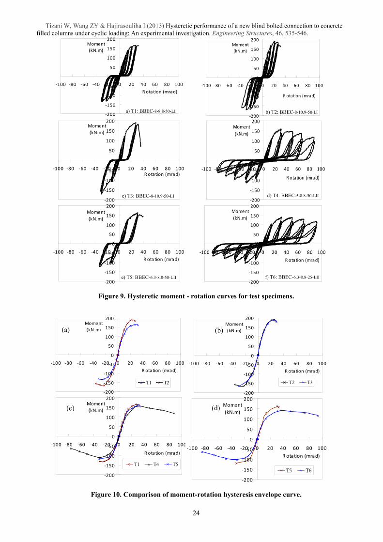
beam-to-column connections. The hysteretic moment-rotation curves of the tested connections are shown in
Figure 9. The key characteristics of the connection, such as moment capacity, rotation capacity and initial
stiffness are summarized in Table 3.
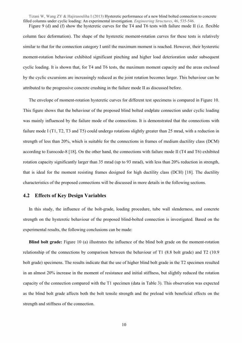
Figure 9 (a), (b), (c), and (e) show the hysteretic moment-rotation curves for the tests T1, T2, T3, and T5
that all failed in the mode I (i.e. bolt fracture). The hysteretic curves for these tests exhibit minor pinching.
The rotation increment along zero moment axis of loading and unloading excursions indicates that the joint
rotation is governed by the bolt shank elongation or slip rather than the plate flexibility. This is because this
rotation was not accompanied by noticeable load increment. Moreover, it is noted that the areas enclosed by
the cyclic excursion of the first loading cycle for each displacement level are slightly larger than those
generated by subsequent cycles. This observation will be discussed in more detail in the following section.
9
Tizani W, Wang ZY & Hajirasouliha I (2013) Hysteretic performance of a new blind bolted connection to concrete
filled columns under cyclic loading: An experimental investigation. Engineering Structures, 46, 535-546. Figure 9 (d) and (f) show the hysteretic curves for the T4 and T6 tests with failure mode II (i.e. flexible
column face deformation). The shape of the hysteretic moment-rotation curves for these tests is relatively
similar to that for the connection category I until the maximum moment is reached. However, their hysteretic
moment-rotation behaviour exhibited significant pinching and higher load deterioration under subsequent
cyclic loading. It is shown that, for T4 and T6 tests, the maximum moment capacity and the areas enclosed
by the cyclic excursions are increasingly reduced as the joint rotation becomes larger. This behaviour can be
attributed to the progressive concrete crushing in the failure mode II as discussed before.
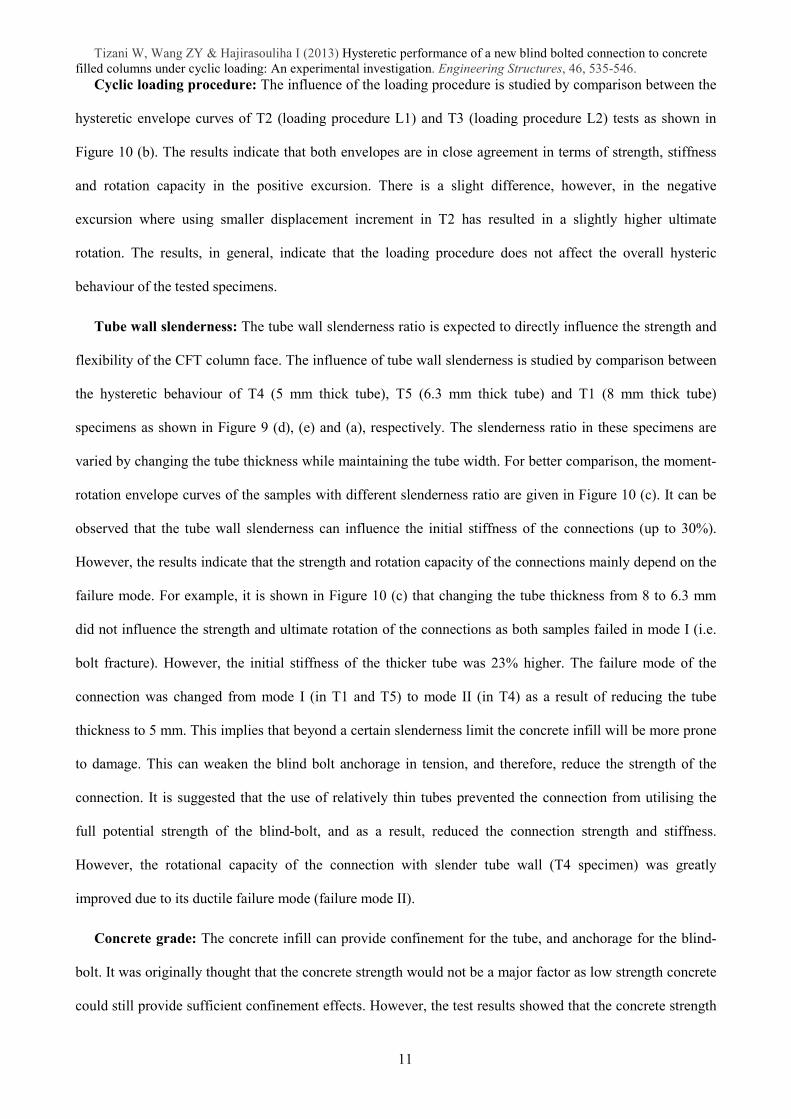
The envelope of moment-rotation hysteretic curves for different test specimens is compared in Figure 10.
This figure shows that the behaviour of the proposed blind bolted endplate connection under cyclic loading
was mainly influenced by the failure mode of the connections. It is demonstrated that the connections with
failure mode I (T1, T2, T3 and T5) could undergo rotations slightly greater than 25 mrad, with a reduction in
strength of less than 20%, which is suitable for the connections in frames of medium ductility class (DCM)
according to Eurocode-8 [18]. On the other hand, the connections with failure mode II (T4 and T6) exhibited
rotation capacity significantly larger than 35 mrad (up to 93 mrad), with less than 20% reduction in strength,
that is ideal for the moment resisting frames designed for high ductility class (DCH) [18]. The ductility
characteristics of the proposed connections will be discussed in more details in the following sections.
4.2 Effects of Key Design Variables
In this study, the influence of the bolt-grade, loading procedure, tube wall slenderness, and concrete
strength on the hysteretic behaviour of the proposed blind-bolted connection is investigated. Based on the
experimental results, the following conclusions can be made:
Blind bolt grade: Figure 10 (a) illustrates the influence of the blind bolt grade on the moment-rotation
relationship of the connections by comparison between the behaviour of T1 (8.8 bolt grade) and T2 (10.9
bolt grade) specimens. The results indicate that the use of higher blind bolt grade in the T2 specimen resulted
in an almost 20% increase in the moment of resistance and initial stiffness, but slightly reduced the rotation
capacity of the connection compared with the T1 specimen (data in Table 3). This observation was expected
as the blind bolt grade affects both the bolt tensile strength and the preload with beneficial effects on the
strength and stiffness of the connection.
10
Tizani W, Wang ZY & Hajirasouliha I (2013) Hysteretic performance of a new blind bolted connection to concrete
filled columns under cyclic loading: An experimental investigation. Engineering Structures, 46, 535-546. Cyclic loading procedure: The influence of the loading procedure is studied by comparison between the
hysteretic envelope curves of T2 (loading procedure L1) and T3 (loading procedure L2) tests as shown in
Figure 10 (b). The results indicate that both envelopes are in close agreement in terms of strength, stiffness
and rotation capacity in the positive excursion. There is a slight difference, however, in the negative
excursion where using smaller displacement increment in T2 has resulted in a slightly higher ultimate
rotation. The results, in general, indicate that the loading procedure does not affect the overall hysteric
behaviour of the tested specimens.
Tube wall slenderness: The tube wall slenderness ratio is expected to directly influence the strength and
flexibility of the CFT column face. The influence of tube wall slenderness is studied by comparison between
the hysteretic behaviour of T4 (5 mm thick tube), T5 (6.3 mm thick tube) and T1 (8 mm thick tube)
specimens as shown in Figure 9 (d), (e) and (a), respectively. The slenderness ratio in these specimens are
varied by changing the tube thickness while maintaining the tube width. For better comparison, the moment-
rotation envelope curves of the samples with different slenderness ratio are given in Figure 10 (c). It can be
observed that the tube wall slenderness can influence the initial stiffness of the connections (up to 30%).
However, the results indicate that the strength and rotation capacity of the connections mainly depend on the
failure mode. For example, it is shown in Figure 10 (c) that changing the tube thickness from 8 to 6.3 mm
did not influence the strength and ultimate rotation of the connections as both samples failed in mode I (i.e.
bolt fracture). However, the initial stiffness of the thicker tube was 23% higher. The failure mode of the
connection was changed from mode I (in T1 and T5) to mode II (in T4) as a result of reducing the tube
thickness to 5 mm. This implies that beyond a certain slenderness limit the concrete infill will be more prone
to damage. This can weaken the blind bolt anchorage in tension, and therefore, reduce the strength of the
connection. It is suggested that the use of relatively thin tubes prevented the connection from utilising the
full potential strength of the blind-bolt, and as a result, reduced the connection strength and stiffness.
However, the rotational capacity of the connection with slender tube wall (T4 specimen) was greatly
improved due to its ductile failure mode (failure mode II).
Concrete grade: The concrete infill can provide confinement for the tube, and anchorage for the blind-
bolt. It was originally thought that the concrete strength would not be a major factor as low strength concrete
could still provide sufficient confinement effects. However, the test results showed that the concrete strength
11
Tizani W, Wang ZY & Hajirasouliha I (2013) Hysteretic performance of a new blind bolted connection to concrete
filled columns under cyclic loading: An experimental investigation. Engineering Structures, 46, 535-546. can significantly affect the behaviour of CFT columns with relatively high tube wall slenderness ratio. The
influence of the concrete compressive strength can be observed by comparison between the hysteretic
behaviour of tests T5 (concrete strength of 53 N/mm2) and T6 (concrete strength of 21 N/mm
2) as shown in
Figure 9 (e) and (f) and Figure 10 (d). It is immediately apparent that the concrete strength has influenced the
failure mode of the connections (mode I in T6 and mode II in T5). Using low strength concrete resulted in a
17% reduction in the rotation capacity, 18% reduction in the initial stiffness, and 260% increase in the
rotation capacity as the failure mode changed from type I (i.e. bolt fracture) to type II (i.e. flexible column
face deformation). It is clear from the results that the low strength concrete led to the failure of bolt
anchorage, and as a result the tensile stiffness of the blind-bolt was controlled by the tube-wall alone. This
was confirmed by inspecting the failed samples (Figure 8) where it is observed that the concrete anchorage
was hardly damaged for failure mode I (T5 specimen) but it was completely crushed for samples with failure
mode II (T4 and T6 specimens). It is also worth noting that the overall behaviour of the weak-concrete
connection (T5) is comparable to that of the relatively weak tube wall connection (T4) with the exception of
the ultimate moment strength.
5 CYCLIC CHARACTERISTICS OF THE CONNECTIONS
The cyclic performance of the connections with different material and geometric parameters are evaluated
and discussed in this section. The assessment is based on the data obtained from tests T1 and T2, as
representatives of failure mode I (i.e. bolt fracture), and T4 and T6, as representatives of connections with
failure mode II (i.e. flexible column face deformation).
5.1 Key Performance Parameters
The performance parameters studied in this study are strength and stiffness degradation, ductility, and
energy dissipation ratio based on the ECCS [23] and ATC [24] recommendations. Brief definitions of these
parameters are given below and the symbols are described in Table 4 and Table 5.
Ductility: Ductility is defined as the ability of the structure to undergo large plastic deformation without
significant loss of strength [25]. The concept of ductility is a key element in earthquake-resistant design of
structures. The assessment of ductility for connections can be carried out by calculating partial ductility (ȝ0i)
and full ductility ratio (ȝfi) as defined in Table 5. The partial ductility indicates the capability of the
12
Tizani W, Wang ZY & Hajirasouliha I (2013) Hysteretic performance of a new blind bolted connection to concrete
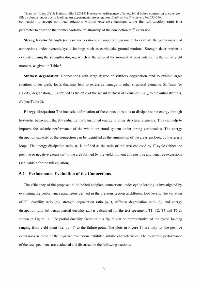
filled columns under cyclic loading: An experimental investigation. Engineering Structures, 46, 535-546. connection to accept nonlinear rotations without extensive damage, while the full ductility ratio is a
parameter to describe the moment-rotation relationship of the connection at ith excursion.
Strength ratio: Strength (or resistance) ratio is an important parameter to evaluate the performance of
connections under dynamic/cyclic loadings such as earthquake ground motions. Strength deterioration is
evaluated using the strength ratio, Įri, which is the ratio of the moment at peak rotation to the initial yield
moment, as given in Table 5.
Stiffness degradation: Connections with large degree of stiffness degradation tend to exhibit larger
rotations under cyclic loads that may lead to extensive damage to other structural elements. Stiffness (or
rigidity) degradation, つ, is defined as the ratio of the secant stiffness at excursion i, Ks,i, to the initial stiffness,
Ke (see Table 5).
Energy dissipation: The inelastic deformation of the connections aids to dissipate some energy through
hysteretic behaviour, thereby reducing the transmitted energy to other structural elements. This can help to
improve the seismic performance of the whole structural system under strong earthquakes. The energy
dissipation capacity of the connection can be identified as the summation of the areas enclosed by hysteresis
loops. The energy dissipation ratio, Și, is defined as the ratio of the area enclosed by ith cycle (either the
positive or negative excursion) to the area formed by the yield moment and positive and negative excursions
(see Table 5 for the full equation).
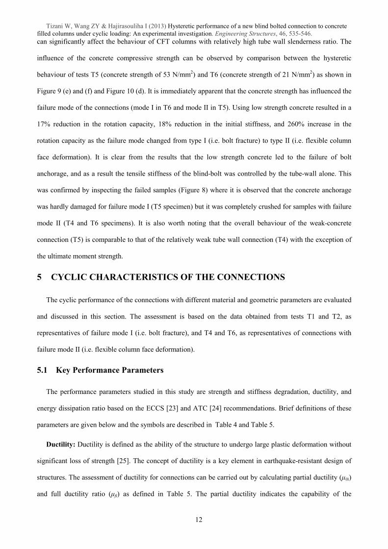
5.2 Performance Evaluation of the Connections
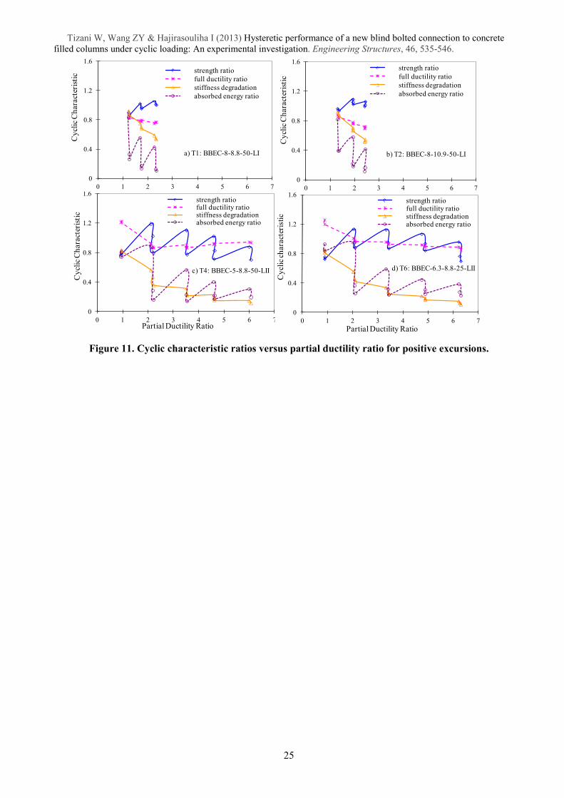
The efficiency of the proposed blind bolted endplate connections under cyclic loading is investigated by
evaluating the performance parameters defined in the previous section at different load levels. The variation
of full ductility ratio (ȝf), strength degradation ratio (Įr ), stiffness degradation ratio (つ), and energy
dissipation ratio (Ș) versus partial ductility (ȝ0) is calculated for the test specimens T1, T2, T4 and T6 as
shown in Figure 11. The partial ductility factor in this figure can be representative of the cyclic loading
ranging from yield point (i.e. ȝ0 =1) to the failure point. The plots in Figure 11 are only for the positive
excursions as those of the negative excursions exhibited similar characteristics. The hysteretic performance
of the test specimens are evaluated and discussed in the following sections.
13

Tizani W, Wang ZY & Hajirasouliha I (2013) Hysteretic performance of a new blind bolted connection to concrete
filled columns under cyclic loading: An experimental investigation. Engineering Structures, 46, 535-546.
5.2.1 Connection Ductility
As it was expected, T4 and T6 specimens with the failure mode II (i.e. flexible column face deformation)
exhibited significantly higher ductility compared to T1 and T2 specimens with the failure mode I (i.e. bolt
fracture). The results shown in Figure 11 indicate that the partial ductility factor for the connections failed by
mode I and mode II was on average 2.7 (i.e. medium ductility class) and 6.1 (high ductility class),
respectively. This is in agreement with the classifications based on plastic rotation capacity as discussed in
section 4.1.
Comparison of partial ductility and full ductility ratios for different test specimens in Figure 11 shows an
almost identical behaviour for the specimens with similar failure modes. This implies that the ductility of the
blind bolted endplate connections to CFT columns was mainly influenced by the failure mode rather than
other design variables. It is shown in Figure 11 (a) and (b) that the full ductility ratio of T1 and T2 specimens
had an almost linear descending tendency up to the failure point, which indicates a modest deterioration of
the hysteresis loops in the connections with type I failure. Figure 11 (c) and (d) show a steep drop in the full
ductility ratio of T4 and T6 specimens after the first set of cycles with an almost level performance beyond
that. The sudden reduction can be attributed to partial or full failure of the bolt embedment in the concrete
that would change the joint rotational resistance mechanism from tension in the bolt to simultaneous local
concrete crushing and face bending. Beyond the second set of load cycles, there is a slight deterioration in
the ductility performance of the T4 and T6 connections. This indicates that this connection category (limited
by the face bending failure mode) has much larger rotational capacity compared to the connections with bolt-
controlled failure mode.
5.2.2 Strength Ratio
Comparison of the strength ratios in Figure 11 indicates that samples with similar failure modes exhibited
very similar behaviour. This emphasises the dominant role of the failure modes on the hysteretic behaviour
of the connections. Figure 11 (a) and (b), show an improved resistance (relative to the yield strength) for T1
and T2 specimens, with failure mode I, up to the failure point. The only moderate degradation of strength
was between successive cycles of the same amplitude, and no overall significant strength degradation was
noticed before failure.
14
Tizani W, Wang ZY & Hajirasouliha I (2013) Hysteretic performance of a new blind bolted connection to concrete
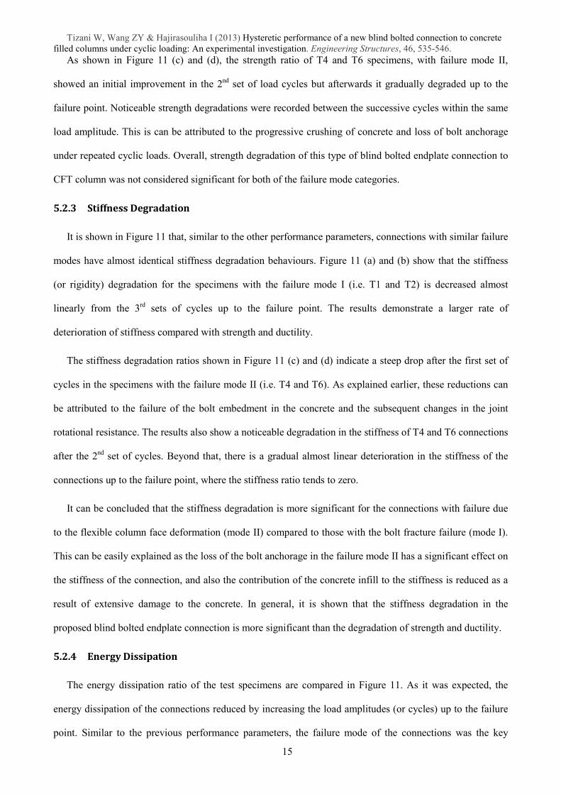
filled columns under cyclic loading: An experimental investigation. Engineering Structures, 46, 535-546. As shown in Figure 11 (c) and (d), the strength ratio of T4 and T6 specimens, with failure mode II,
showed an initial improvement in the 2nd
set of load cycles but afterwards it gradually degraded up to the
failure point. Noticeable strength degradations were recorded between the successive cycles within the same
load amplitude. This is can be attributed to the progressive crushing of concrete and loss of bolt anchorage
under repeated cyclic loads. Overall, strength degradation of this type of blind bolted endplate connection to
CFT column was not considered significant for both of the failure mode categories.
5.2.3 Stiffness Degradation
It is shown in Figure 11 that, similar to the other performance parameters, connections with similar failure
modes have almost identical stiffness degradation behaviours. Figure 11 (a) and (b) show that the stiffness
(or rigidity) degradation for the specimens with the failure mode I (i.e. T1 and T2) is decreased almost
linearly from the 3rd
sets of cycles up to the failure point. The results demonstrate a larger rate of
deterioration of stiffness compared with strength and ductility.
The stiffness degradation ratios shown in Figure 11 (c) and (d) indicate a steep drop after the first set of
cycles in the specimens with the failure mode II (i.e. T4 and T6). As explained earlier, these reductions can
be attributed to the failure of the bolt embedment in the concrete and the subsequent changes in the joint
rotational resistance. The results also show a noticeable degradation in the stiffness of T4 and T6 connections
after the 2nd
set of cycles. Beyond that, there is a gradual almost linear deterioration in the stiffness of the
connections up to the failure point, where the stiffness ratio tends to zero.
It can be concluded that the stiffness degradation is more significant for the connections with failure due
to the flexible column face deformation (mode II) compared to those with the bolt fracture failure (mode I).
This can be easily explained as the loss of the bolt anchorage in the failure mode II has a significant effect on
the stiffness of the connection, and also the contribution of the concrete infill to the stiffness is reduced as a
result of extensive damage to the concrete. In general, it is shown that the stiffness degradation in the
proposed blind bolted endplate connection is more significant than the degradation of strength and ductility.
5.2.4 Energy Dissipation
The energy dissipation ratio of the test specimens are compared in Figure 11. As it was expected, the
energy dissipation of the connections reduced by increasing the load amplitudes (or cycles) up to the failure
point. Similar to the previous performance parameters, the failure mode of the connections was the key
15
Tizani W, Wang ZY & Hajirasouliha I (2013) Hysteretic performance of a new blind bolted connection to concrete
filled columns under cyclic loading: An experimental investigation. Engineering Structures, 46, 535-546. element for determining their energy dissipation capacity. In general, connections with failure mode II
demonstrated higher energy dissipation ratio.
Figure 11 (a) and (b) show a significant drop in the energy dissipation capacity of T1 and T2 specimens
(failure mode I) after the first cycle of loading. Beyond this point, a gradual decrease is noticed until the
failure point. Similarly, Figure 11 (c) and (d) show a steep drop in the energy dissipation ratio of T4 and T6
specimens (failure mode II) after the first set of cycles with almost gradual descending performance beyond
that. For both categories of connections, there was a dramatic drop of the absorbed energy ratio subsequent
to the first cycle of each loading amplitude, which implies the absorbed energy reduces significantly during
the repeated cycles. However, it can be observed that the amount of such reduction is reduced as the cyclic
loading proceeds. This phenomenon can be explained by the fact that after a few cycles the energy is mainly
dissipated by flexible deformation of the tube connecting face (as a plate element), rather than the sole action
of the blind bolt in tensile deformation.
The results of this study indicate that the new blind bolted endplate connection to CFT column, in
general, can offer good energy dissipation capacity and ductility which makes it suitable for seismic
applications. It is particularly true for the connections in category II (failure due to flexible column face
deformation) that exhibit high ductility and relatively low strength degradation under cyclic loading. In
practice, the seismic performance of this type of connections can be significantly improved by controlling
their failure mode in the design process (for example by using relatively thin tube face and/or low strength
concrete). The experimental results and related analysis presented in this paper can be taken as a basic
reference for the efficient design of this innovative blind bolted endplate connection to CFT columns.
Development of detailed finite element and analytical macro models to simulate the hysteretic moment-
rotation relationship of this type of connection will be discussed in a companion paper.
6 SUMMARY AND CONCLUSIONS
A series of six full-scale tests were conducted on a new blind bolted endplate connection to CFT columns
using EHB under quasi-static cyclic loading. The strength, stiffness degradation, ductility, rotation capacity
and energy dissipation of the connections were evaluated in relation to different material and geometric
parameters. The primary results can be summarized as follows:
16
Tizani W, Wang ZY & Hajirasouliha I (2013) Hysteretic performance of a new blind bolted connection to concrete
filled columns under cyclic loading: An experimental investigation. Engineering Structures, 46, 535-546. (1) The test observations indicate two representative failure modes. In failure mode I, described as weak
blind bolt-strong CFT column, the bolt shank fractured ultimately with limited CFT column face yielding. In
failure mode II, described as strong blind bolt- weak CFT column, the CFT column face deformed in a
flexible manner with local damage of concrete infill and partial bolt pull-out. Connections with failure mode
II exhibited significantly higher rotation capacity and ductility compared to those with failure mode I.
(2) During the cyclic loading tests, no damage was observed on the extension of the blind bolts. This
suggests that the proposed bolt can provide stable improvement in strength and stiffness of the connection as
long as the surrounded concrete is not crushed along the anchor nut.
(3) The strength, stiffness, and rotation capacity of the connections are rather insensitive to the loading
amplitude of the cyclic loading procedure. The use of higher bolt grade increases the maximum strength and
initial stiffness of the connections, but slightly reduces the counterpart rotation capacity. Any decrease in
tube wall thickness and concrete grade is normally accompanied by a decrease in the strength and stiffness of
the connection. However, this can change the failure mechanism of the connection from mode I to mode II
which leads to a significant increase in the ultimate rotation and ductility.
(4) It is shown that the overall performance of the blind bolted endplate connections was mainly
influenced by their failure mode. In general, connections with failure mode II (strong blind bolt- weak CFT
column) demonstrated high energy dissipation and ductility ratio, and therefore, can be used in moment-
resisting frames designed for high ductility class (HDC) that are suitable for high seismic zones.
7 ACKNOWLEDGEMENTS
The authors would like to thank Mr. Trevor Mustard and Mr. Andrew Orton of Tata Steel (formerly
known as Corus) and Mr Neil F. Gill of Lindapter International for supporting this work. The second author
would like to acknowledge financial support from �UK/China Scholarship for Excellence� programme for his
doctoral research work.
REFERENCES
1. Bergmann R, Matsui C, Meinsma C, Dutta D. Design Guide for Concrete Filled Section Columns under
static and Seismic Loading. CIDECT. 1995.
2. Kurobane Y, Packer JA, Wardenier J, Yeomans N., Design Guide for Structural Hollow Section Column
Connections. CIDECT and Verlag TüV Rheinland GmbH, Koln, Germany, 2004.
3. Alostaz YM, Schneider SP., Analytical behavior of connections to concrete-filled steel tubes. Journal of
Constructional Steel Research. 1996(40): 95-127
4. Schneider SP, Alostaz YM., Experimental behavior of connections to concrete-filled steel tubes. Journal
of Constructional Steel Research. 1998(45): 321-352
17
Tizani W, Wang ZY & Hajirasouliha I (2013) Hysteretic performance of a new blind bolted connection to concrete
filled columns under cyclic loading: An experimental investigation. Engineering Structures, 46, 535-546. 5. Mahin SA., Lessons from damage to steel buildings during the Northridge earthquake. Engineering
Structures, 20(4-6), 1998: 261-270
6. Barnett, T.C., Tizani, W. and Nethercot, D.A., 2001. The practice of blind bolting connections to
structure hollow sections - a review Steel and Composite Structures. 1(1), 1-16
7. Ellison S, Tizani W., Behaviour of blind bolted connections to concrete filled hollow sections. The
Structual Engineer, November, 2004: 16-17
8. Wang ZY, Tizani W, Wang QY., Strength and initial stiffness of a blind-bolt connection based on the T-
stub model, Engineering Structures, 32(9), 2010: 2505-2517
9. Tizani.W, Ridley-Ellis.D.J. The performance of a new blind-bolt for moment-resisting connections. In:
Jaurietta MA, Alonso A, Chica JA, editors. Tubular structures X: Proceedings of the 10th international
symposium on tubular structures. Rotterdam: A. A. Balkema, 2003: 395-400
10. Al-Mughairi, A, Tizani, W And Owen, J S, 2010. Validation Of An FE Model For An Experimental
Blind-Bolted Moment-Resisting Connection To Concrete Filled Hollow Section
11. Elghazouli AY, et al. Experimental monotonic and cyclic behaviour of blind-bolted angle connections.
Engineering Structures (2009), Volume 31, Issue 11, November 2009, Pages 2540�2553,
doi:10.1016/j.engstruct.2009.05.021
12. Gardner, A.P.; Goldsworthy, H.M., Experimental investigation of the stiffness of critical components in
a moment-resisting composite connection. Journal of Constructional Steel Research vol. 61 issue 5 May,
2005. p. 709-726, DOI: 10.1016/j.jcsr.2004.11.004. ISSN: 0143-974X.
13. France JE, Davison JB, Kirby PA., Strength and rotational response of moment connections to tubular
columns using flowdrill connectors. Journal of Constructional Steel Research, 50(1), 1999: 35-48
14. Loh HY, Uy B, Bradford MA., The effects of partial shear connection in composite flush end plate joints
Part I- experimental study. Journal of Constructional Steel Research, 62(4), 2006: 378-390
15. Goldsworthy H, Gardner AP., Feasibility study for blind bolted connections to concrete-filled circular
steel tubular columns. Structural Engineering and Mechanics, 24(4), 2006: 463-478
16. Wang JF, Chen XY, Han LH., Structural behaviour of blind bolted connection to concrete-filled steel
tubular columns. Advanced Material Research, 163-167, 2011: 591-595
17. FEMA(350), Recommended seismic design criteria for new steel moment frame buildings. SAC Joint
Venture, Federal Emergency Management Agency, Washington D.C, 2000
18. Eurocode 8: Design of structures for earthquake resistance - Part 1: General rules, seismic actions. BS
EN 1998-1:2004, British Standard Institute, January 2011
19. Elghazouli AY, Málaga-Chuquitaype C, Castro JM, Orton AH., Experimental monotonic and cyclic
behaviour of blind-bolted angle connections. Engineering Structures, Vol. 31(11), 2009:2540-2553
20. EN 10002-1, Metallic materials: tensile testing, Part 1: Method of test at ambient temperature. London:
British Standards Institution, 2001
21. Wang ZY., Hysteretic response of an innovative blind bolted endplate connection to concrete filled
tubular column. PhD Thesis, University of Nottingham, United Kingdom, 2012
22. FEMA 356, Prestandard and Commentary for the Seismic Rehabilitation of Buildings, Federal
Emergency Management Agency, November, 2000
23. ECCS. Technical Committee 1:structutal safety and loadings: technical working group 1.3:seismic
design, recommended testing procedure for assessing the behaviour of structural steel elements under
cyclic loads, 1986
24. Guidelines for Cyclic Testing of Components of Steel Structures, ATC Applied Technology Council,
ATC-24, 1992
25. Mazzolani FM., Moment resistant connections of steel frames in seismic areas. E&FN SPON Press.
2000: 95-96
18
Tizani W, Wang ZY & Hajirasouliha I (2013) Hysteretic performance of a new blind bolted connection to concrete
filled columns under cyclic loading: An experimental investigation. Engineering Structures, 46, 535-546. Table 1. Details of test specimens.
Test
No.
Specimen reference
BBEC-tc-bgr-cgr-lp
SHS column section Blind bolt Concrete
Nominal
bc×bc×t0
(mm)
Actual
bc×bc×t0
(mm)
Bolt
grade
Tightening
torque (Nm)
Strength
(N/mm2)
1 BBEC-8-8.8-50-LI 200×200×8 201.5×201.5×7.91 8.8 190 53.20
2 BBEC-8-10.9-50-LI 200×200×8 201.5×201.5×7.91 10.9 300 47.40
3 BBEC-8-10.9-50-LII 200×200×8 201.5×201.5×7.91 10.9 300 51.55
4 BBEC-5-8.8-50-LII 200×200×5 201.2×201.2×4.92 8.8 190 49.13
5 BBEC-6.3-8.8-50-LII 200×200×6.3 201.1×201.1×6.27 8.8 190 52.75
6 BBEC-6.3-8.8-25-LII 200×200×6.3 201.1×201.1×6.27 8.8 190 20.77 Note: Connecting steel beam size: UB 356×171×67, endplate size (mm): 404×220×25, blind bolt size: M16.
Table 2. Properties of steel components
Steel components Yield strength (MPa) Ultimate strength (MPa) Elastic modulus (MPa)
Beam & endplate 500.20 581.18 194205
SHS tube 5mm 433.05 522.10 197194
6.3mm 423.23 514.59 190512
8mm 435.05 510.68 199114
Bolt shank 8.8 grade 752.33 918.18 194204
10.9 grade 883.43 1112.32 209722
Bolt Sleeve 449.40 584.33 208830
Table 3. Summary of main results
Test
No.
Yield point Maximum moment point Peak rotation point Initial stiffness
(KN.m/mrad) Failure
modes
Yield moment
( kN.m)
Yield rotation
(mrad)
Moment
( kN.m)
Rotation
(mrad)
Moment
( kN.m)
Rotation
(mrad)
My- My
+ θy- θy
+ Mmax- Mmax
+ θm,max- θm,max
+ Mr, peak- Mr, peak
+ θpeak- θpeak
+ Kini- Kini
+
T1 120.7 154.0 12.4 12.1 133.8 163.9 30.6 27.3 130.8 161.8 31.3 32.2 16.9 23.5 I
T2 149.0 173.0 12.0 11.3 164.7 189.0 22.3 21.8 154.6 166.4 36.7 34.9 20.1 27.1 I
T3 151.1 177.0 11.9 11.2 171.9 189.2 29.4 27.7 156.9 180.1 29.8 31.6 20.2 28.6 I
T4 107.2 132.5 15.5 14.4 115.8 157.7 32.1 30.5 62.2 116.7 77.2 86.5 14.1 18.0 II
T5 116.5 144.8 13.5 13.1 120.4 161.0 31.1 30.3 108.9 147.5 32.3 35.7 15.8 19.2 I
T6 97.1 121.2 15.4 14.9 103.0 137.3 30.6 30.4 64.6 110.2 83.3 92.8 13.7 16.2 II
+ or � denotes positive or negative excursion
Table 4. Definition of cyclic parameters [23, 24]
Symbols Definition
Moment My+, My
- Yield moment based on envelop curve
Mi+, Mi
- Moment at peak rotation in excursion i+ & i-
Rotation θ y+, θ y
- Yield rotation in first excursion
θ i +
, θi- Peak rotation in excursion i+ & i-
∆θi+, ∆θ i- Rotation range from θ y to the max in excursion i+ & i-
Stiffness Ks,i+, Ks,i
- The secant slope of M-θ diagram at excursion i+ & i-
Ke+, Ke
- Initial stiffness of M-θ diagram at the start
Energy Ai+
, Ai- Area enclosed by hysteresis loops for excursions i+ & i-
Table 5. Definition of cyclic characterising parameters [23, 24]
Cyclic characterizing parameters Symbol Expressions
Partial ductility ȝ0i θ i +
/θy+, θi
-/θy
-
Full ductility ratio ȝfi ǻθ i+/(θ i +
+θi-−θy
-),ǻθ i-/(θ i
++θi
-−θy+)
Strength or resistance ratio Įri Mi+/My
+, Mi
-/My
-
Stiffness degradation ratio ȟi Ks,i+/Ke
+, Ks,i
-/Ke
-
Energy dissipation ratio Și Ai
+/ [My
+(θi
+-θy
++θi
--θy
-)]
Ai-/ [My
-(θi
--θy
-+θi
+-θy
+)]
19
Tizani W, Wang ZY & Hajirasouliha I (2013) Hysteretic performance of a new blind bolted connection to concrete
filled columns under cyclic loading: An experimental investigation. Engineering Structures, 46, 535-546.
No. Components
A Bolt head
B Collar
C Rubber washer
D Sleeve
E Threaded cone
F Bolt shank
G Anchor nut
Figure 1. Components of the proposed Extended Hollobolt (EHB).
Figure 2. Configuration of the connections.
Section A-A
Endplate
Blind bolt
Beam ends Strain gauge
LVDT
Potentiometer
a. Before tightening b. After tightening
Eۑ
Aۑ
Bۑ
Dۑ
Cۑ
Fۑ
Gۑ
20
Tizani W, Wang ZY & Hajirasouliha I (2013) Hysteretic performance of a new blind bolted connection to concrete
filled columns under cyclic loading: An experimental investigation. Engineering Structures, 46, 535-546.
(a) Plan view
(b) Elevation view
a Test steel beam g Lateral & end block m Rigid link
b Horizontal actuator h Load cell n Link roller: rotation
c Reaction buttress i Frame column o Link roller: translation
d Test CFT column j Brace p Sliding base
e Test endplate k Strong floor q Local support & packing
f Blind bolts l Head cap r Out-of-plane restraint & tie-downs
Figure 3. Schematic of test-setup
Figure 4. Picture of test arrangement (top view).
21
Tizani W, Wang ZY & Hajirasouliha I (2013) Hysteretic performance of a new blind bolted connection to concrete
filled columns under cyclic loading: An experimental investigation. Engineering Structures, 46, 535-546.
Figure 5. Schematic graph of joint rotation relationships.
Figure 6. Definition of the yield point of the connection [22]
Figure 7. Illustration of the ECCS cyclic loading procedures [23]
-6
-5
-4
-3
-2
-1
0
1
2
3
4
5
6
0 1 2 3 4 5 6 7 8 9 10 11 12 13
δ/δ y
Cycle number
Procedure I
Procedure II
M
θpeak θ
Mm
My
0.6 My
θy
αKe
Ke
22
Tizani W, Wang ZY & Hajirasouliha I (2013) Hysteretic performance of a new blind bolted connection to concrete
filled columns under cyclic loading: An experimental investigation. Engineering Structures, 46, 535-546.
Figure 8. Representative failure modes of the connections.
Failure mode I (Test T1~T3, T5) Failure mode II (Test T4 & T6)
Connec
tion a
ssem
bly
(a)
(b)
CF
T c
olu
mn
fac
e
Yield lines
(c)
Yield lines
(d)
CF
T c
olu
mn c
oncr
ete
infi
ll Local concrete crushing
(e)
Remaining solid concrete infill
(f)
Bli
nd
bo
lts
(g)
(h)
T1 T2 T3
Bolt shank rupture &
stripped bolt head
Bolt sleeve local
Bolt rupture Column face is
flexible
23
Tizani W, Wang ZY & Hajirasouliha I (2013) Hysteretic performance of a new blind bolted connection to concrete
filled columns under cyclic loading: An experimental investigation. Engineering Structures, 46, 535-546.
Figure 9. Hysteretic moment - rotation curves for test specimens.
Figure 10. Comparison of moment-rotation hysteresis envelope curve.
-200
-150
-100
-50
0
50
100
150
200
-100 -80 -60 -40 -20 0 20 40 60 80 100
R otation (mrad)
Moment
(kN.m)
-200
-150
-100
-50
0
50
100
150
200
-100 -80 -60 -40 -20 0 20 40 60 80 100
R otation (mrad)
Moment
(kN.m)
Moment
(kN.m)
-200
-150
-100
-50
0
50
100
150
200
-100 -80 -60 -40 -20 0 20 40 60 80 100
R otation (mrad)
-200
-150
-100
-50
0
50
100
150
200
-100 -80 -60 -40 -20 0 20 40 60 80 100
R otation (mrad)
Moment
(kN.m)
-200
-150
-100
-50
0
50
100
150
200
-100 -80 -60 -40 -20 0 20 40 60 80 100
R otation (mrad)
Moment
(kN.m)
-200
-150
-100
-50
0
50
100
150
200
-100 -80 -60 -40 -20 0 20 40 60 80 100
R otation (mrad)
Moment
(kN.m)
-200
-150
-100
-50
0
50
100
150
200
-100 -80 -60 -40 -20 0 20 40 60 80 100
R otation (mrad)
Moment
(kN.m)
T1 T2
-200
-150
-100
-50
0
50
100
150
200
-100 -80 -60 -40 -20 0 20 40 60 80 100
R otation (mrad)
Moment
(kN.m)
T2 T3
-200
-150
-100
-50
0
50
100
150
200
-100 -80 -60 -40 -20 0 20 40 60 80 100
R otation (mrad)
Moment
(kN.m)
T1 T4 T5
-200
-150
-100
-50
0
50
100
150
200
-100 -80 -60 -40 -20 0 20 40 60 80 100
R otation (mrad)
Moment
(kN.m)
T5 T6
b) T2: BBEC-8-10.9-50-LI a) T1: BBEC-8-8.8-50-LI
c) T3: BBEC-8-10.9-50-LI d) T4: BBEC-5-8.8-50-LII
e) T5: BBEC-6.3-8.8-50-LII f) T6: BBEC-6.3-8.8-25-LII
(a) (b)
(c) (d)
24
Tizani W, Wang ZY & Hajirasouliha I (2013) Hysteretic performance of a new blind bolted connection to concrete
filled columns under cyclic loading: An experimental investigation. Engineering Structures, 46, 535-546.
Figure 11. Cyclic characteristic ratios versus partial ductility ratio for positive excursions.
0
0.4
0.8
1.2
1.6
0 1 2 3 4 5 6 7
Cy
clic
Ch
ara
cter
isti
c
strength ratio
full ductility ratio
stiffness degradation
absorbed energy ratio
b) T2: BBEC-8-10.9-50-LI
0
0.4
0.8
1.2
1.6
0 1 2 3 4 5 6 7
Cy
clic
Ch
ara
cter
isti
c
Partial Ductility Ratio
strength ratiofull ductility ratiostiffness degradation absorbed energy ratio
c) T4: BBEC-5-8.8-50-LII
0
0.4
0.8
1.2
1.6
0 1 2 3 4 5 6 7
Cy
clic
Ch
ara
cter
isti
cstrength ratio
full ductility ratio
stiffness degradation
absorbed energy ratio
a) T1: BBEC-8-8.8-50-LI
0
0.4
0.8
1.2
1.6
0 1 2 3 4 5 6 7
Cy
clic
ch
ara
cter
isti
c
Partial Ductility Ratio
strength ratiofull ductility ratiostiffness degradation absorbed energy ratio
d) T6: BBEC-6.3-8.8-25-LII
25