HyPro: A Multi-DoF Hybrid-Powered Transradial Robotic ...
16
Research Article HyPro: A Multi-DoF Hybrid-Powered Transradial Robotic Prosthesis C. L. Semasinghe , R. K. P. S. Ranaweera, J. L. B. Prasanna, H. M. Kandamby, D. G. K. Madusanka, and R. A. R. C. Gopura Bionics Laboratory, Department of Mechanical Engineering, University of Moratuwa, Moratuwa, Sri Lanka Correspondence should be addressed to C. L. Semasinghe; [email protected] Received 20 May 2017; Revised 21 October 2017; Accepted 16 November 2017; Published 1 March 2018 Academic Editor: Yangmin Li Copyright © 2018 C. L. Semasinghe et al. is is an open access article distributed under the Creative Commons Attribution License, which permits unrestricted use, distribution, and reproduction in any medium, provided the original work is properly cited. is paper proposes a multi-DoF hybrid-powered transradial robotic prosthesis, named HyPro. e HyPro consists of two prosthetic units: hand and wrist that can achieve five grasping patterns such as power grasp, tip grasp, lateral grasp, hook grasp, and index point. It is an underactuated device with 15 degrees of freedom. A hybrid powering concept is proposed and implemented on hand unit of HyPro where the key focus is on restoration of grasp functions of biological hand. A novel underactuated mechanism is introduced to achieve the required hand preshaping for a given grasping pattern using electric power in the pregrasp stage and body power is used in grasp stage to execute the final grasping action with the selected fingers. Unlike existing hybrid prostheses where each of the joints is separately controlled by either electric or body power, the proposed prosthesis is capable of delivering grasping power in combination. e wrist unit of HyPro is designed and developed to achieve flexion-extension and supination-pronation using electric power. Experiments were carried out to evaluate the functionality and performance of the proposed hybrid-powered robotic prosthesis. e results verified the potential of HyPro to perform intended grasping patterns effectively and efficiently. 1. Introduction Transradial amputations refer to loss of both biological hand and wrist and are the most common form of upper extremity amputation according to statistics [1]. Traumatic accidents, vascular complications, and congenital deformity are notable causes leading to transradial amputation [1]. Transradial prosthesis is used as a wearable device by the transradial amputees. It consists of an artificial wrist and a terminal device which are either mechanically or electromechani- cally operated [2, 3]. Although there had been a marked improvement in functionality, performance, and appearance of subsequent generations of transradial prostheses, the robotic counterparts are still lacking in certain areas to restore or mimic the missing segments of the biological limb [3]. In particular, most transradial prostheses are designed to perform a few of the grasping tasks with limited degrees of freedom (DoF), in comparison to the biological wrist and hand that have 27 DoF [4]. In general, effectiveness of transradial prostheses has been determined based on power consumption, weight, mobility, appearance, and size of the device [5]. ese also serve as benchmarks to compare and contrast different prosthetic developments. According to literature, three main categories of transradial prostheses can be identified based on method of powering: nonpowered, body-powered, and externally powered prostheses [3]. Nonpowered or cosmetic transradial prostheses are made considering anthropome- try and appearance of hand and characteristically do not have any or limited functional capabilities [6]. At present, body-powered transradial prostheses are the most popular prostheses since they are lightweight, simple in operation, easily maintained, economical, and importantly capable of restoring certain functions of the biological hand [6]. Since they can only perform maximum two grasping actions from a single terminal device, different terminal devices are required to fulfill various activities of daily living (ADL) [7]. e externally powered transradial prostheses are mostly operated by means of electric and pneumatic actuators. ese prostheses exhibit higher functional capabilities compared to other two categories. However, externally powered tran- sradial prostheses are typically limited in operation due to Hindawi Journal of Robotics Volume 2018, Article ID 8491073, 15 pages https://doi.org/10.1155/2018/8491073
Transcript of HyPro: A Multi-DoF Hybrid-Powered Transradial Robotic ...

Research ArticleHyPro: A Multi-DoF Hybrid-Powered TransradialRobotic Prosthesis
C. L. Semasinghe , R. K. P. S. Ranaweera, J. L. B. Prasanna, H. M. Kandamby,D. G. K. Madusanka, and R. A. R. C. Gopura
Bionics Laboratory, Department of Mechanical Engineering, University of Moratuwa, Moratuwa, Sri Lanka
Correspondence should be addressed to C. L. Semasinghe; [email protected]
Received 20 May 2017; Revised 21 October 2017; Accepted 16 November 2017; Published 1 March 2018
Academic Editor: Yangmin Li
Copyright © 2018 C. L. Semasinghe et al.This is an open access article distributed under theCreativeCommonsAttributionLicense,which permits unrestricted use, distribution, and reproduction in any medium, provided the original work is properly cited.
This paper proposes a multi-DoF hybrid-powered transradial robotic prosthesis, named HyPro. The HyPro consists of twoprosthetic units: hand and wrist that can achieve five grasping patterns such as power grasp, tip grasp, lateral grasp, hook grasp, andindex point. It is an underactuated device with 15 degrees of freedom. A hybrid powering concept is proposed and implemented onhand unit of HyProwhere the key focus is on restoration of grasp functions of biological hand. A novel underactuatedmechanism isintroduced to achieve the required hand preshaping for a given grasping pattern using electric power in the pregrasp stage and bodypower is used in grasp stage to execute the final grasping action with the selected fingers. Unlike existing hybrid prostheses whereeach of the joints is separately controlled by either electric or body power, the proposed prosthesis is capable of delivering graspingpower in combination. The wrist unit of HyPro is designed and developed to achieve flexion-extension and supination-pronationusing electric power. Experiments were carried out to evaluate the functionality and performance of the proposed hybrid-poweredrobotic prosthesis. The results verified the potential of HyPro to perform intended grasping patterns effectively and efficiently.
1. Introduction
Transradial amputations refer to loss of both biological handand wrist and are the most common form of upper extremityamputation according to statistics [1]. Traumatic accidents,vascular complications, and congenital deformity are notablecauses leading to transradial amputation [1]. Transradialprosthesis is used as a wearable device by the transradialamputees. It consists of an artificial wrist and a terminaldevice which are either mechanically or electromechani-cally operated [2, 3]. Although there had been a markedimprovement in functionality, performance, and appearanceof subsequent generations of transradial prostheses, therobotic counterparts are still lacking in certain areas to restoreor mimic the missing segments of the biological limb [3].In particular, most transradial prostheses are designed toperform a few of the grasping tasks with limited degrees offreedom (DoF), in comparison to the biological wrist andhand that have 27DoF [4].
In general, effectiveness of transradial prostheses hasbeen determined based on power consumption, weight,
mobility, appearance, and size of the device [5]. These alsoserve as benchmarks to compare and contrast differentprosthetic developments. According to literature, three maincategories of transradial prostheses can be identified basedon method of powering: nonpowered, body-powered, andexternally powered prostheses [3]. Nonpowered or cosmetictransradial prostheses are made considering anthropome-try and appearance of hand and characteristically do nothave any or limited functional capabilities [6]. At present,body-powered transradial prostheses are the most popularprostheses since they are lightweight, simple in operation,easily maintained, economical, and importantly capable ofrestoring certain functions of the biological hand [6]. Sincethey can only perform maximum two grasping actionsfrom a single terminal device, different terminal devices arerequired to fulfill various activities of daily living (ADL)[7].The externally powered transradial prostheses are mostlyoperated bymeans of electric and pneumatic actuators.Theseprostheses exhibit higher functional capabilities comparedto other two categories. However, externally powered tran-sradial prostheses are typically limited in operation due to
HindawiJournal of RoboticsVolume 2018, Article ID 8491073, 15 pageshttps://doi.org/10.1155/2018/8491073
2 Journal of Robotics
high power consumption, complexity in operation, reliability,bulkiness, and overweight of the device [7].
Elimination of these limitations may enable theresearchers and developers to derive a suitable replacementfor a missing limb segment. One approach in realizing thisis to introduce a hybrid powering concept where the deviceis given the capability of functioning with both body andexternal power [8]. There are no considerable applicationsof this concept in context of prosthetic limbs, and yethybrid-powered prostheses are in the introductory phase ofits life cycle. In literature, handful number of researches areidentified in relation to hybrid-powered prosthesis wheremost of them use different units in combination that operateindependently by either electric or body power [9, 10].
Therefore, this paper proposes a novel hybrid poweringconcept with the key focus on grasp restoration by actuatingprosthetic thumb and fingers using both electric and bodypower. In addition, a novel underactuated mechanism isproposed for the prosthetic hand unit to perform differentgrasping patterns. The notion of adaptive grasping is alsoconsidered for the development of prosthetic fingers. Themechanism uses electric power to achieve hand preshapingaccording to the intended grasping pattern and body powerto execute the desired grasping action. Here, the roboticprosthesis is designed to carry out five grasping patterns,namely, power grasp, tip grasp, lateral grasp, hook grasp,and index point which are commonly used in ADL. As aresult of introducing the hybrid powering concept in theform of a novel finger actuation mechanism, the prosthetichand only requires two electric actuators to perform theselected grasping patterns. Here one electric motor is usedto flex and extend the three-digit prosthetic fingers whilethe second electric motor is used to arrange thumb position.Therefore, the proposed prosthetic hand unit is essentially anunderactuated device with 15DoF. The shoulder retraction-protraction is used to deliver the required body powerto complete the grasping action. The prosthetic wrist unitproposed in this paper is fully electric-powered unit thathas only two DoF controlled by two servomotors. The fullyassembled prosthesis is designed to be worn by a transradialamputee using a socket placed on the residual limb and acommonly available harness mechanism is used to transmitthe body power.
The paper is organized as follows. Section 2 reviewsthe state-of-the-art transradial prostheses to identify theircapabilities and shortcomings. Section 3 briefly discussesmotion requirements for transradial amputee with anatom-ical and biomechanical factors. Section 4 presents the designof the proposed transradial prosthesis. The mechanism ofthe HyPro is described in Section 5 and the experiments arepresented in Section 6. Section 7 discusses the experimentalresults. Section 8 concludes the paper.
2. Related Work
One of the key limiting factors of transradial robotic pros-thesis is its weight. It can be found from the literature thatthere is a direct relationship between device weight andnumber of active DoF [8]. As an example, devices such as
DEKA RC Gen3 arm [18], DLR/HIT II hand [19, 20], andMANUS hand [21] show higher weights than the deviceslike uGrip II [22], i-limb ultra [23], and Michelangelo [24]because of the availability of higher active DoF. Generally,this occurs due to the consequences of increasing numberof actuators to achieve high active DoF. In response, theresearchers have comewith underactuatedmechanismwhichcouples the multiple movements to single actuator. However,such advancements have also failed to achieve significantweight reduction due to added weight of additional mechan-ical coupling and/or linkage systems [8]. Generally, theselection of required number of actuators depends on thedesirable grasping patterns for which the robotic prosthesisis designed. It is important to have independently controlledactuators in developing a dexterous hand with individualfinger movements. However, it is possible to achieve an arrayof grasping pattern actuation by using the coupling strategiessuch as differential clutching and linkage mechanism whichminimizes the actuators required to operate the prosthesis.
Majority of prostheses are developed based on tendon-based and linkage-basedmechanisms to achieve fingermove-ments [8]. Ability to miniaturize the end effector is the keyadvantage of the tendon-based mechanisms used in the mosttransradial prosthetic devices. This advantage is mainly dueto the ability of placing the actuators away from joints offingers. In addition, the tendon-based mechanism helps inreducing bulkiness of the end effector while reducing thecomplexity of operation of prosthetic fingers [8]. However,this mechanism is known to have some drawbacks as well.The friction between tendon and tendon enclosures or slidinggroves results in inefficiencies in power transmission. Thedurability of tendon is also a major concern. The four-barlinkage is themost common linkage-basedmechanism foundin the transradial prostheses. Such mechanisms generallyshowcase efficient power transmission while producing highgrasping force and good grasp stability. However, prostheticfingers or the end effectors are bulky when considering mostprosthetic hands. In addition, the complexity of operationand higher weight are other factors associated with linkage-based mechanism. However, new linkage-based conceptshave now been developed for underactuated mechanismswhere some devices enable the passive finger control andenhance the object grasping capabilities. As an example, ARhand III is a novel anthropomorphic robot hand which has 15joints driven only by three motors which is purely based onunderactuated mechanism [25].
When powering of the robotic prostheses is considered,body-powered prostheses like HOSMER HOOK model 88Xand OTTOBOCK hooks are light weight and simple tooperate [24, 26]. However, they are limited to restoring a fewgrasping patterns mainly due to the usage of body powerto operate. The electrically powered prostheses like i-limbultra, Bebionic 3, and Michelangelo have more functionalcapabilities than body-powered device but have limitationsarising due to bulkiness, weight, and complexity of operation[23, 24, 27]. The major drawback of those devices is theirreliance on battery power. By combining favorable featuresfound in each prosthetic limb into one prosthesis, most of thelimitations can be mitigated.

Journal of Robotics 3
(a) (b) (c) (d) (e)
(f) (g) (h) (i) (j) (k)
Figure 1: Motions of below elbow extremity (adapted from [14]) and common grasping patterns (adapted from [15]). (a) Forearm supination-pronation, (b) flexion-extension of hand, (c) radial-ulnar deviation of hand, (d) finger abduction-adduction, (e) finger flexion-extension, (f)power grasp, (g) index point, (h) lateral grasp, (i) tip grasp, (j) chuck or spherical grasp, and (k) Hook grasp.
Middle phalange
Distal phalange
Flexion-extension axis
Radial-ulnar axisUlna
Radius Proximal phalanx
MetacarpalRadiocarpal
joint
Carpal bones
Interphalangeal
Proximal interphalangeal
Metacarpophalangeal
Distal interphalangeal
Proximal phalange
Figure 2: Anatomy of wrist and hand.
3. Motion Requirement ofTransradial Amputee
A transradial prosthesis should ideally restore the motionrequirement of the biological hand and wrist. In order toachieve this task, anatomy and biomechanics of the upperlimb should be closely studied. The following section sum-marizes the salient aspects considered in developing theproposed hybrid-powered transradial prosthesis.
The below elbow upper limb consists of forearm, wrist,and hand.The radioulnar joint in the forearm facilitates wristsupination-pronation (see Figure 1). The wrist consists oftwo joints, namely, radiocarpal and midcarpal joints, whichare located at the distal ends of the radial and ulna bones(see Figure 2). Radiocarpal joint allows flexion-extensionand radial-ulnar deviation at the wrist [28]. The range ofmotion (RoM) for each DoF at wrist joint discussed aboveis summarized in Table 1.
Human hand consists of 27 bones, 29 joints, more than30 muscles, and tendons to actuate the joints for the purposeof motion generation [29]. In order to handle various objects,joints of fingers are arranged in different configurations. All3-digit fingers are comprised of metacarpophalangeal (MP),proximal interphalangeal (PIP), and distal interphalangeal(DIP) joints while thumb has only interphalangeal (IP) andmetacarpophalangeal (MP) joints [12] as shown in Figure 2.
The joints in the five fingers provide 21DoF for graspingobjects that may vary in size, shape, and weight. The thumbhas five DoF whereas other fingers only four. The flexion-extension of fingers are generated by three separate joints [12].The abduction-adduction of fingers is only generated at theMCP joint. Table 2 lists RoM of each finger with respect torest position as indicated in Figures 1(d) and 1(e).
The hand is capable of generating required articulationto support ADL. There are numerous finger arrangements,known as grasping patterns to perform several grasping
4 Journal of Robotics
(a) (b) (c) (d)
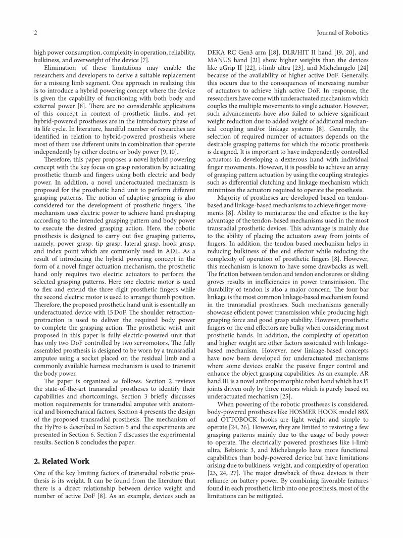
Figure 3: Sequence of steps followed to grasp a cylindrical object [16]: (a) approach of the finger, (b) contact of the first phalange, (c) contactof the second phalange, and (d) contact of the third phalange.
Table 1: Range of motions of wrist [11, 12].
Motion RangeFlexion-extension 0∘–75∘/0∘–(−70∘)Radial deviation-ulnar deviation 0∘–20∘/0∘–(−35∘)Supination-pronation 0∘–90∘/0∘–(−90∘)
actions. The main function of the prosthesis is to mimicthe most important grasping patterns used in day-to-daylife [30]. During the grasp action, the fingers undergo twomain stages which are pregrasp and grasp execution [31].In the pregrasp stage, the fingers arrange for achieving thedesired grasping pattern while reorienting the hand. Theaction of gripping the target will be performed during thegrasp execution stage [31]. For example, when an averageperson wants to hold an iron, first the hand gets preparedfor grasping during its pregrasp stage which is in the reach-to-grasp motion. Then grasp is executed by holding the ironby the desired grasp posture which is power grasp [31]. Inthe ADL, power grasp, index point, and lateral grasp arefrequently used grasping patterns which are shown in Figures1(f)–1(h) [30]. According to the literature, power grasp is themostly employed grasping pattern with a frequency of 40% ofADL [30, 32]. Furthermore, frequencies of use of index fingerextension, precision grasp, lateral grasp, and hook grasp are13%, 12%, 7%, and 0.2%, respectively [15].
Finger adaptation is considered to be the most importantfeature when developing a prosthesis. Most of the prostheticfingers are developed to generate human-like grasping action.During grasping of a cylindrical object, the phalanges of theprosthetic or biological finger follow the basic sequence ofoperations shown in Figure 3 [16, 33].
4. Design of HyPro
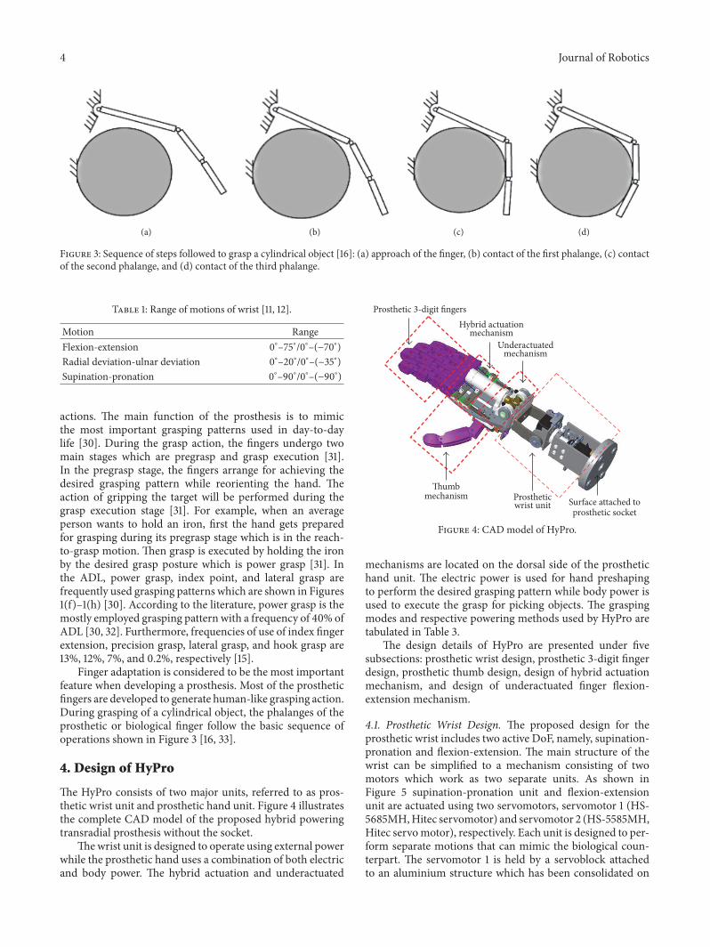
The HyPro consists of two major units, referred to as pros-thetic wrist unit and prosthetic hand unit. Figure 4 illustratesthe complete CAD model of the proposed hybrid poweringtransradial prosthesis without the socket.
Thewrist unit is designed to operate using external powerwhile the prosthetic hand uses a combination of both electricand body power. The hybrid actuation and underactuated
Surface attached toprosthetic socket
Prostheticwrist unit
Prosthetic 3-digit fingersHybrid actuation
mechanismUnderactuated
mechanism
Thumbmechanism
Figure 4: CAD model of HyPro.
mechanisms are located on the dorsal side of the prosthetichand unit. The electric power is used for hand preshapingto perform the desired grasping pattern while body power isused to execute the grasp for picking objects. The graspingmodes and respective powering methods used by HyPro aretabulated in Table 3.
The design details of HyPro are presented under fivesubsections: prosthetic wrist design, prosthetic 3-digit fingerdesign, prosthetic thumb design, design of hybrid actuationmechanism, and design of underactuated finger flexion-extension mechanism.
4.1. Prosthetic Wrist Design. The proposed design for theprosthetic wrist includes two active DoF, namely, supination-pronation and flexion-extension. The main structure of thewrist can be simplified to a mechanism consisting of twomotors which work as two separate units. As shown inFigure 5 supination-pronation unit and flexion-extensionunit are actuated using two servomotors, servomotor 1 (HS-5685MH,Hitec servomotor) and servomotor 2 (HS-5585MH,Hitec servomotor), respectively. Each unit is designed to per-form separate motions that can mimic the biological coun-terpart. The servomotor 1 is held by a servoblock attachedto an aluminium structure which has been consolidated on

Journal of Robotics 5
Hand attachment unit (C bracket)
Wrist base unit
Wrist supination-pronation unit
Wrist flexion-extension unit
Servomotor
Servomotor
R1
R2
Figure 5: 2-DoF prosthetic wrist of HyPro.
Table 2: RoM of fingers [11, 13].
Motion/joint FingerThumb Index Middle Ring Little
Flexion-extensionMCP 0∘–70∘ (−30∘)–90∘ (−20∘)–90∘ (−30∘)–90∘ (−30∘)–90∘
PIP - 0∘–120∘ 0∘–120∘ 0∘–120∘ 0∘–120∘
DIP 0∘–90∘ 0∘–80∘ 0∘–80∘ 0∘–80∘ 0∘–80∘
Abduction-adduction MCP (−50∘)–40∘ (−25∘)–20∘ (−25∘)–20∘ (−25∘)–20∘ (−25∘)–20∘
Opposition - reposition CMC (−9∘)–31∘ - - - -
Table 3: Grasping and powering methods of HyPro.
Grasping mode Powering methodPower grasp Body powerIndex push Electric powerTip grasp Body and electric powerHook grasp Electric powerLateral grasp Body power
the wrist base unit. The servoblock contains an aluminiumhub to transmit torque from the motor to prosthetic handthrough the flexion-extension unit (see Figure 5). Flexion-extension unit is directly coupled with the hub of servoblockto transmit the torque of servomotor 1. The servomotor 2 isused to generate torque for wrist flexion-extension motionand the C-bracket is used to attach the prosthetic hand to theflexion-extension unit.
4.2. Prosthetic 3-Digit Finger Design. Thefingers are designedconsidering 95th percentile anthropometric data of malepopulation in the world [34]. The prosthetic finger closelymatches the biological human finger from a functional pointof view. The passive extension and adaptive grasping of pha-langes have been achieved by employing elastic straps on thedorsal side of the prosthetic fingers. Different strap patterns
were introduced between phalanges and the overall stiffnessof the elastic straps was found to be 38.8N/m from thephysical experiments conducted on prosthetic finger samples.All the prosthetic fingers in HyPro are designed to workusing a tendon-basedmechanismwhere the finger gets flexedwhen the flexor tendon is pulled. Therefore, the prosthetichand is voluntarily opened because of the extended fingersdue to relaxation of elastic straps under zero force on theflexor tendons. Figure 6 shows the 3Dmodel of the proposedprosthetic finger. Each of the segments of the prostheticfinger was fabricated from PLA material using 3D printingtechnology and 3mm stainless steel pins were inserted toform the hinges. Finite element simulations were performedto assess the load bearing capacity of the prosthetic finger.Stress field plots indicate that regions nearby the hinges aremost vulnerable for failure. However, each of the fingers isdesigned to bear 5 kg of force with a safety factor of 2.
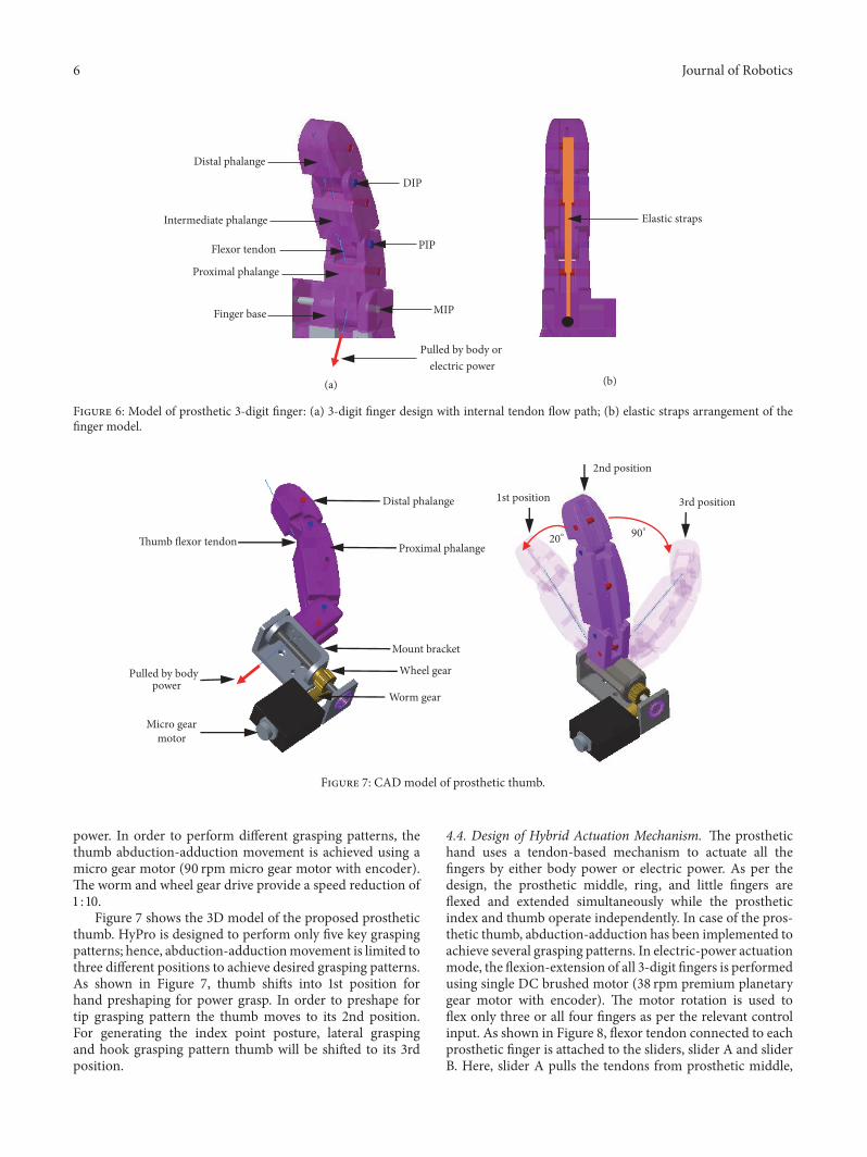
4.3. Prosthetic Thumb Design. As in the case of 3-digitfingers, the prosthetic thumb is equipped with a tendon-based mechanism to flex the thumb. It is comprised of twophalanges similar to the biological thumb. In order to achievepassive extension and adaptive grasping abilities, two springswith different force constants were attached to each of thephalanges. The flexion-extension motion of the prostheticthumb is achieved by pulling the flexor tendon using body
6 Journal of Robotics
Flexor tendon
DIP
PIP
MIP
Distal phalange
Intermediate phalange
Proximal phalange
Finger base
Pulled by body or electric power
(a)
Elastic straps
(b)
Figure 6: Model of prosthetic 3-digit finger: (a) 3-digit finger design with internal tendon flow path; (b) elastic straps arrangement of thefinger model.
Micro gear motor
Worm gear
Wheel gear
Thumb flexor tendon
Mount bracket
Proximal phalange
Pulled by body power
Distal phalange 1st position
2nd position
3rd position
20∘90∘
Figure 7: CAD model of prosthetic thumb.
power. In order to perform different grasping patterns, thethumb abduction-adduction movement is achieved using amicro gear motor (90 rpm micro gear motor with encoder).The worm and wheel gear drive provide a speed reduction of1 : 10.
Figure 7 shows the 3D model of the proposed prostheticthumb. HyPro is designed to perform only five key graspingpatterns; hence, abduction-adductionmovement is limited tothree different positions to achieve desired grasping patterns.As shown in Figure 7, thumb shifts into 1st position forhand preshaping for power grasp. In order to preshape fortip grasping pattern the thumb moves to its 2nd position.For generating the index point posture, lateral graspingand hook grasping pattern thumb will be shifted to its 3rdposition.
4.4. Design of Hybrid Actuation Mechanism. The prosthetichand uses a tendon-based mechanism to actuate all thefingers by either body power or electric power. As per thedesign, the prosthetic middle, ring, and little fingers areflexed and extended simultaneously while the prostheticindex and thumb operate independently. In case of the pros-thetic thumb, abduction-adduction has been implemented toachieve several grasping patterns. In electric-power actuationmode, the flexion-extension of all 3-digit fingers is performedusing single DC brushed motor (38 rpm premium planetarygear motor with encoder). The motor rotation is used toflex only three or all four fingers as per the relevant controlinput. As shown in Figure 8, flexor tendon connected to eachprosthetic finger is attached to the sliders, slider A and sliderB. Here, slider A pulls the tendons from prosthetic middle,

Journal of Robotics 7
MGN5C linear carriage
MGN5R linear guide rail
Tendon from index finger
Tendon from middle finger
Tendon from ring finger
Tendon from little finger
Slider tendon B(connected to slider B)
Slider tendon C(connected to
slider B)
Slider tendon A(connected to slider A)
Slider B
Slider A
Attached to pulley B
(motor-driven)
Attached to pulley A
(motor-driven)Pulled by body power
Figure 8: CAD model of the hybrid actuation mechanism.
ring, and little fingers while slider B pulls the tendon fromprosthetic index finger.
Each slider is fixed on two carriage blocks (HIWINMGN5C) where those carriage blocks linearly move on twolinear guide rails (HIWIN MGN5R). Here both sliders canslide along the guide rail independently. Figure 8 illustratesthe tendon connection to each of the sliders in HyPro. Inorder to flex prosthetic middle, ring and little fingers sliderA has to be pulled by the slider tendon A. When the slidertendon B is pulled, the slider B moves linearly along thelinear guide rails while pushing the slider A aswell.Therefore,pulling the slider tendon B causes all four fingers to beflexed. Both slider tendon A and B are pulled using the sameDC brushed motor which is electrically powered. The slidertendonC is designed to be pulled by body powerwhichmakesall four fingers flexed after pulling. Therefore, all four 3-digitfingers can be flexed by either pulling slider tendon B usingDC brushed motor or pulling slider tendon C using bodypower. If the slider A is pulled by slider tendon A using DCbrushed motor, the slider tendon C allows only index fingerto flex or extend by pulling or releasing, respectively. Whenthe effort on pulling slider tendons is released the fingersextend due to passive extension mechanism implemented oneach finger. Here, the linear carriages and linear guide railshave been selected to satisfy the space requirement and towithstand the contact forces that occur on each slider due tounsymmetrical force distribution.
4.5. Underactuated Finger Flexion-Extension Mechanism. InHyPro, an underactuated mechanism is implemented toachieve finger flexion-extension with electric power. The
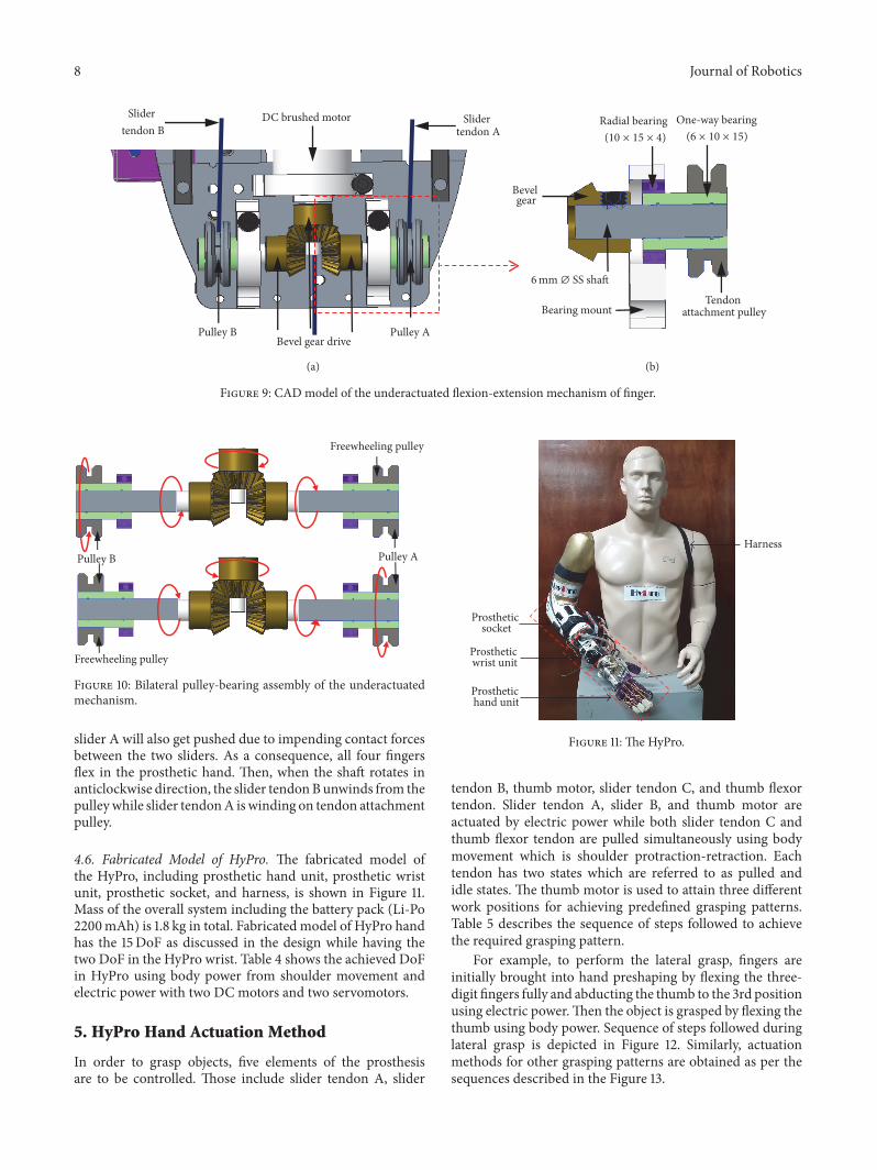
proposed underactuated mechanism has resulted in reduc-tion of weight and simplification of overall control of theprosthesis. This is mainly due to elimination of motors.However, the mechanism found inside HyPro is capable ofperforming five different grasping patterns using a singlemotor with the assistance of body power. When the DCmotor gets actuated either slider tendon A or B winds onthe pulleys causing the fingers to flex as planned. In orderto pull one slider at a given instance, a simple mechanismhas been implemented using couple of bearings. As shownin Figure 9(a), combinations of one-way and radial bearingsare employed to achieve independent pulley rotation.
A one-way bearing allows a shaft inside to rotate freelyonly in one direction. If this one-way bearing is mountedinside a radial bearing as shown in Figure 9(b), the innerracer of the radial bearing will rotate when the shaft rotatesin opposite direction due to the constrain of the shaft insidethe one-way bearing. Figure 10 shows the working principalof the bilateral pulley-bearing assembly which explains theindependent pulley movement capability using a single DCmotor. Note that the tendon attachment pulley is mountedon the outer surface of one-way bearing and the pulley willonly rotate when the one-way bearing is rotating inside theradial bearing.
When the motor shaft rotates in anticlockwise directiononly, pulley A will rotate while pulling the slider A. It resultsin flexing prosthetic middle, ring, and little fingers. If themotor rotates in clockwise direction, only pulley B will rotate.The motion causes slider B to be pulled and slider tendon Atries to unwind from the pulley to release the strain energystored in elastic straps. However, when slider B is pulled,
8 Journal of Robotics
Bearing mount
Radial bearing One-way bearing
Tendon attachment pulley
DC brushed motorSlider tendon B
Slider tendon A
Bevel gear
6mm ∅ SS shaft
(a) (b)
(6 × 10 × 15)(10 × 15 × 4)
Pulley BBevel gear drive
Pulley A
Figure 9: CAD model of the underactuated flexion-extension mechanism of finger.
Pulley B Pulley A
Freewheeling pulley
Freewheeling pulley
Figure 10: Bilateral pulley-bearing assembly of the underactuatedmechanism.
slider A will also get pushed due to impending contact forcesbetween the two sliders. As a consequence, all four fingersflex in the prosthetic hand. Then, when the shaft rotates inanticlockwise direction, the slider tendonBunwinds from thepulleywhile slider tendonA iswinding on tendon attachmentpulley.
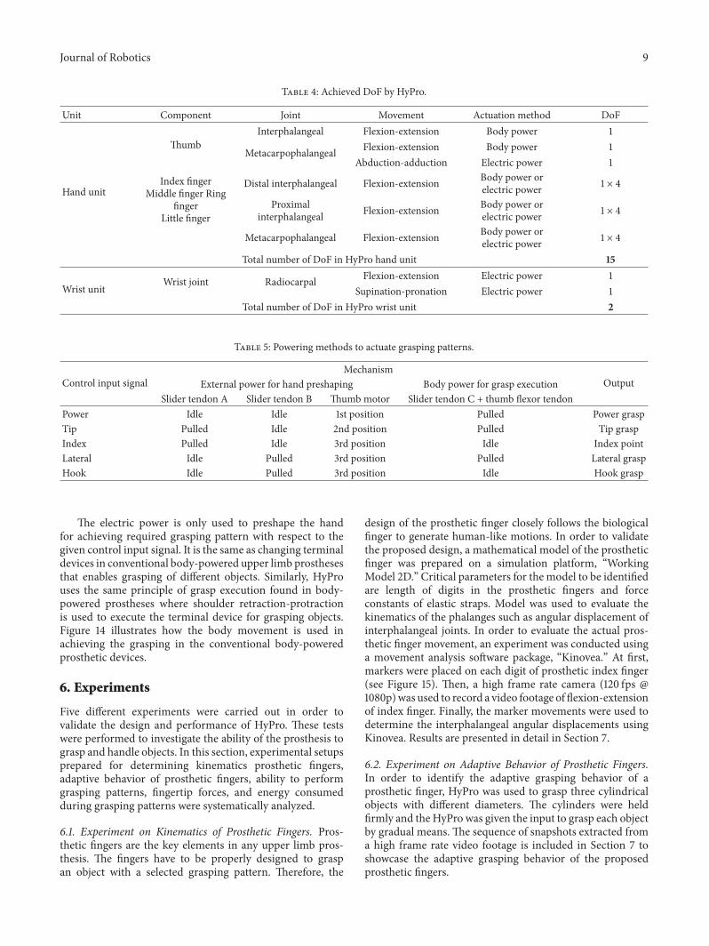
4.6. Fabricated Model of HyPro. The fabricated model ofthe HyPro, including prosthetic hand unit, prosthetic wristunit, prosthetic socket, and harness, is shown in Figure 11.Mass of the overall system including the battery pack (Li-Po2200mAh) is 1.8 kg in total. Fabricated model of HyPro handhas the 15DoF as discussed in the design while having thetwo DoF in the HyPro wrist. Table 4 shows the achieved DoFin HyPro using body power from shoulder movement andelectric power with two DC motors and two servomotors.
5. HyPro Hand Actuation Method
In order to grasp objects, five elements of the prosthesisare to be controlled. Those include slider tendon A, slider
Prosthetic hand unit
Prosthetic wrist unit
Harness
Prosthetic socket
Figure 11: The HyPro.
tendon B, thumb motor, slider tendon C, and thumb flexortendon. Slider tendon A, slider B, and thumb motor areactuated by electric power while both slider tendon C andthumb flexor tendon are pulled simultaneously using bodymovement which is shoulder protraction-retraction. Eachtendon has two states which are referred to as pulled andidle states. The thumb motor is used to attain three differentwork positions for achieving predefined grasping patterns.Table 5 describes the sequence of steps followed to achievethe required grasping pattern.
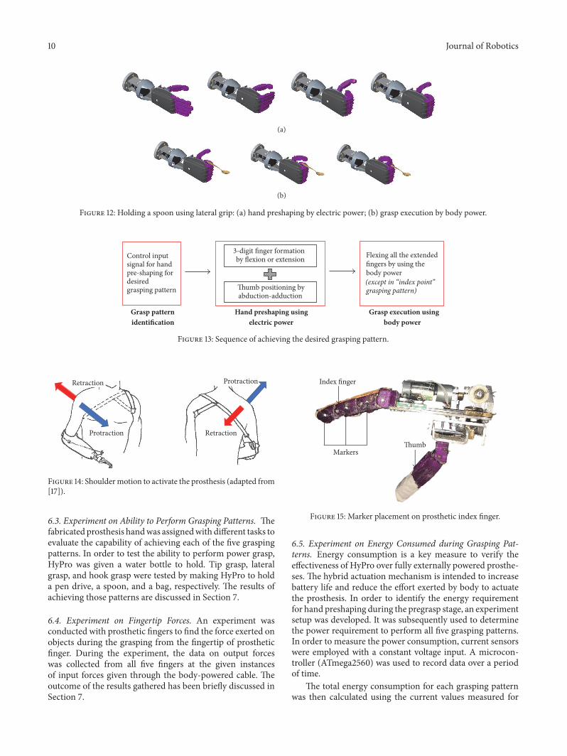
For example, to perform the lateral grasp, fingers areinitially brought into hand preshaping by flexing the three-digit fingers fully and abducting the thumb to the 3rd positionusing electric power.Then the object is grasped by flexing thethumb using body power. Sequence of steps followed duringlateral grasp is depicted in Figure 12. Similarly, actuationmethods for other grasping patterns are obtained as per thesequences described in the Figure 13.
Journal of Robotics 9
Table 4: Achieved DoF by HyPro.
Unit Component Joint Movement Actuation method DoF
Hand unit
ThumbInterphalangeal Flexion-extension Body power 1
Metacarpophalangeal Flexion-extension Body power 1Abduction-adduction Electric power 1
Index fingerMiddle finger Ring
fingerLittle finger
Distal interphalangeal Flexion-extension Body power orelectric power 1 × 4
Proximalinterphalangeal Flexion-extension Body power or
electric power 1 × 4
Metacarpophalangeal Flexion-extension Body power orelectric power 1 × 4
Total number of DoF in HyPro hand unit 15
Wrist unitWrist joint Radiocarpal Flexion-extension Electric power 1
Supination-pronation Electric power 1Total number of DoF in HyPro wrist unit 2
Table 5: Powering methods to actuate grasping patterns.
Control input signalMechanism
OutputExternal power for hand preshaping Body power for grasp executionSlider tendon A Slider tendon B Thumb motor Slider tendon C + thumb flexor tendon
Power Idle Idle 1st position Pulled Power graspTip Pulled Idle 2nd position Pulled Tip graspIndex Pulled Idle 3rd position Idle Index pointLateral Idle Pulled 3rd position Pulled Lateral graspHook Idle Pulled 3rd position Idle Hook grasp
The electric power is only used to preshape the handfor achieving required grasping pattern with respect to thegiven control input signal. It is the same as changing terminaldevices in conventional body-powered upper limb prosthesesthat enables grasping of different objects. Similarly, HyProuses the same principle of grasp execution found in body-powered prostheses where shoulder retraction-protractionis used to execute the terminal device for grasping objects.Figure 14 illustrates how the body movement is used inachieving the grasping in the conventional body-poweredprosthetic devices.
6. Experiments
Five different experiments were carried out in order tovalidate the design and performance of HyPro. These testswere performed to investigate the ability of the prosthesis tograsp and handle objects. In this section, experimental setupsprepared for determining kinematics prosthetic fingers,adaptive behavior of prosthetic fingers, ability to performgrasping patterns, fingertip forces, and energy consumedduring grasping patterns were systematically analyzed.
6.1. Experiment on Kinematics of Prosthetic Fingers. Pros-thetic fingers are the key elements in any upper limb pros-thesis. The fingers have to be properly designed to graspan object with a selected grasping pattern. Therefore, the
design of the prosthetic finger closely follows the biologicalfinger to generate human-like motions. In order to validatethe proposed design, a mathematical model of the prostheticfinger was prepared on a simulation platform, “WorkingModel 2D.” Critical parameters for the model to be identifiedare length of digits in the prosthetic fingers and forceconstants of elastic straps. Model was used to evaluate thekinematics of the phalanges such as angular displacement ofinterphalangeal joints. In order to evaluate the actual pros-thetic finger movement, an experiment was conducted usinga movement analysis software package, “Kinovea.” At first,markers were placed on each digit of prosthetic index finger(see Figure 15). Then, a high frame rate camera (120 fps @1080p)was used to record a video footage of flexion-extensionof index finger. Finally, the marker movements were used todetermine the interphalangeal angular displacements usingKinovea. Results are presented in detail in Section 7.
6.2. Experiment on Adaptive Behavior of Prosthetic Fingers.In order to identify the adaptive grasping behavior of aprosthetic finger, HyPro was used to grasp three cylindricalobjects with different diameters. The cylinders were heldfirmly and theHyPro was given the input to grasp each objectby gradual means. The sequence of snapshots extracted froma high frame rate video footage is included in Section 7 toshowcase the adaptive grasping behavior of the proposedprosthetic fingers.
10 Journal of Robotics
(a)
(b)
Figure 12: Holding a spoon using lateral grip: (a) hand preshaping by electric power; (b) grasp execution by body power.
Control inputsignal for handpre-shaping fordesiredgrasping pattern
(except in “index point”
Flexing all the extendedfingers by using the body power
grasping pattern)
3-digit finger formationby flexion or extension
Thumb positioning byabduction-adduction
Hand preshaping usingelectric power
Grasp execution usingbody power
Grasp patternidentification
Figure 13: Sequence of achieving the desired grasping pattern.
Protraction
Protraction
Retraction
Retraction
Figure 14: Shouldermotion to activate the prosthesis (adapted from[17]).
6.3. Experiment on Ability to Perform Grasping Patterns. Thefabricated prosthesis handwas assignedwith different tasks toevaluate the capability of achieving each of the five graspingpatterns. In order to test the ability to perform power grasp,HyPro was given a water bottle to hold. Tip grasp, lateralgrasp, and hook grasp were tested by making HyPro to holda pen drive, a spoon, and a bag, respectively. The results ofachieving those patterns are discussed in Section 7.
6.4. Experiment on Fingertip Forces. An experiment wasconducted with prosthetic fingers to find the force exerted onobjects during the grasping from the fingertip of prostheticfinger. During the experiment, the data on output forceswas collected from all five fingers at the given instancesof input forces given through the body-powered cable. Theoutcome of the results gathered has been briefly discussed inSection 7.
Markers
Index finger
Thumb
Figure 15: Marker placement on prosthetic index finger.
6.5. Experiment on Energy Consumed during Grasping Pat-terns. Energy consumption is a key measure to verify theeffectiveness of HyPro over fully externally powered prosthe-ses. The hybrid actuation mechanism is intended to increasebattery life and reduce the effort exerted by body to actuatethe prosthesis. In order to identify the energy requirementfor hand preshaping during the pregrasp stage, an experimentsetup was developed. It was subsequently used to determinethe power requirement to perform all five grasping patterns.In order to measure the power consumption, current sensorswere employed with a constant voltage input. A microcon-troller (ATmega2560) was used to record data over a periodof time.
The total energy consumption for each grasping patternwas then calculated using the current values measured for

Journal of Robotics 11
Current sensor 12v DC brushed motor
Figure 16: Experimental setup for obtaining current measure.
ExtensionFlexion
1 2 3 4 5 60Time (s)
0
50
100
150
200
Rota
tiona
l ang
le (d
eg)
Model, proximalModel, intermediateModel, distal
Fabricated, proximalFabricated, intermediateFabricated, distal
Figure 17: Kinematics of index finger.
a given duration. In order to find the power requirementto perform a desired grasping action, a separate 12v DCbrushed motor was used to imitate the effort exerted bybody power. The tendons supposed to be pulled by the bodywere attached to the motor shaft. The current measures wereobtained using the microcontroller while performing desiredgrasping actions. The experimental setup for obtaining thecurrentmeasures to determine energy consumption is shownin Figure 16.
7. Results and Discussion
In this section, the results obtained from the five differentexperiments described in the previous section are brieflydiscussed.
7.1. Kinematics of Prosthetic Finger. The graph in Figure 17shows the results obtained for rotational angles for bothsimulated model and fabricated model of index finger forthe given time instances with reference to finger base. It isnoted that proximal digitmodel stops rotating after 1.7 s while
intermediate digit rotates until 2.1 s during the flexion stage.The distal digit model rotates until 2.5 s during the flexionstage. Thus, it shows that the proximal digit stops rotatingfirst, then intermediate digit, and finally the distal digit duringthe simulated model finger flexion. Although the time valuesobtained on fabricated finger model are leading compared tosimulated model still it has shown the same sequence of digitrotations during the flexion stage.
During the extension stage in both simulated model andfabricated finger, the distal digit starts rotating first, thenintermediate digit and finally the distal digit.When the fingercomes to its rest position all digits stop rotation with refer-ence to finger base. This validates that the prosthetic fingermovement follows the human finger flexion-extension fromboth simulated model and fabricated model. The Figure 17also shows the sequence of snapshots of fabricated prostheticfinger flexion-extension followed by the results shown in thegraph.
7.2. Adaptive Grasping byHyProHand. Theprosthetic fingerswere given 3 tasks to review the adaptive grasping of fingers.As described in the experimental setup, 3 sequences of images(see Figure 18) were obtained to show the adaptive graspmovement in prosthetic fingers.
In all the tasks when the fingers are given an objectto grasp first proximal digit gets contacted with objectsurface and stops rotating aroundmetacarpi-phalangeal jointwhile other intermediate and distal digits are rotating toget contacted with the object. Then the intermediate digitgets contacted with object surface and stop rotating aroundproximal interphalangeal joint. Finally, the distal digit rotatesuntil it gets contacted with the object. Therefore, all thesemovement patterns during the object grasping show theadaptive grasping of objects by the HyPro hand.
7.3. Grasping Patterns and Postures Achieved by HyPro. Inorder to identify the capability of HyPro hand in achievingthe grasping patterns several tasks were given to observe thefunctionality. Figure 19 shows the set of activities achieved byHyPro for given tasks which are rest position, power grasp,index point, tip grasp lateral grasp, and hook grasp. All thetasks were achieved successfully by the HyPro.
It verified that the HyPro is capable of achieving allfive grasping patterns. From the statistics, the consideredset of grasping patterns has frequency of 72.2% out of allgrasping patterns used in ADL [13, 30]. Hence, HyPro iscapable of performing more than 70% of task found inADL.
7.4. Force Exerted by Prosthetic Fingertip. From the results ofthe experiment, average fingertip force is plotted against inputforce given by pulling of the tendon (see Figure 20). It is foundthat at least 3.34N force is needed for starting the flexionmovement in prosthetic fingers and prosthetic finger exerts0.1 N force on the object during the grasp with the incrementof 1 N force of body power. In order to reduce the frictionallosses, an efficient design of tendon flow paths is needed infuture developments.

12 Journal of Robotics
(a)
(b)
(c)
Figure 18: Adaptive grasping of objects: (a) grasping 52mm diameter shaft; (b) grasping 45mm diameter shaft; (c) grasping 32mm diametershaft.
(a) (b) (c)
(d) (e) (f)
Figure 19: Grasping patterns achieved: (a) rest position; (b) power grip; (c) index point; (d) tip grip; (e) lateral grip; (f) hook grip.

Journal of Robotics 13
Table 6: Power for executing the desired grasping patterns.
% of total ADL % of achievablepatterns, 𝑓
Energy, bodypower, 𝑏𝑝 (Ws)
Energy, electricpower, 𝑒𝑝 (Ws)
𝑓 × 𝑏𝑝(Ws)
𝑓 × 𝑒𝑝(Ws)
Power grasp 40% 55.4% 21.21 0 11.75 0.00Index finger extension 13% 18.0% 0 18.79 0.00 3.38Tip grasp 7% 9.7% 3.53 14.83 0.34 1.44Lateral grasp 12% 16.6% 5.3 23.36 0.88 3.88Hook grasp 0.2% 0.3% 0 13.19 0.00 0.04Total energy consumption 12.97 8.74% energy consumption 59.7% 40.3%
0.0
0.1
0.2
0.3
0.4
0.5
0.6
0.7
0.8
y = 0.0955x − 0.2702
Aver
age fi
nger
tip
outp
ut fo
rce (
N)
2 4 6 8 10 120Input force by pulling tendon (N)
Figure 20: Relationship between average fingertip output force andinput force.
7.5. Energy Consumption and Power Saving. The energyrequired for hand preshaping and grasp execution is cal-culated using the electric current values obtained from theexperiments explained in Section 6.4. Table 6 depicts thefrequencies and the energy consumed using body power andelectric power for each grasping patterns. If the hand is fullyoperated by the electric power, the total energy consumptionof the battery would be the combination of both electricand body energy consumption. According to Table 6, HyProhas the ability of saving 59.7% of battery usage compared tobeing fully electrically powered.This considerable amount ofbattery power saving is mainly because of the power graspbeing the most frequent pattern used in ADL. Hence, thehybrid powering concept enables minimizing the batterypower consumption which leads to increase battery life.Moreover, the required power from the body movements ofthe wearer has decreased with the hybrid powering concept.This helpswithmore comfort and reduces fatigue in repetitiveusage of the prosthesis.
Figure 21 shows the energy distribution between bodypower and battery power when performing each grasp.According to the battery power consumption for differentgrasps, the power grasp does not require the battery power.Externally powered prostheses are usable when only thepower is available [8]. However, the HyPro is capable ofperforming power grasp even without the electric power.Therefore, it is one of the key advantages of the hybridpowering concept.
Power grip Index point Tip grip Lateral grip Hook grip
Body powerBattery power
0
20
40
60
80
100
Ener
gy co
nsum
ptio
n (%
)
Figure 21: Energy distribution of each grasping pattern.
8. Conclusion
This paper proposed a hybrid-powered transradial roboticprosthesis, HyPro which can achieve five grasping patterns.The hand unit of HyPro is adopted with hybrid poweringconcept for grasp function restoration by using both bodypower and electric power.The proposed hand unit has 15DoFand actuated only using two electric motors and body power.The wrist unit is capable of achieving two DoF: wrist flexion-extension and supination-pronation.
The complexity of controlling the motors is reducedsince only two motors are used in this robotic prosthesis.Object grasping can be performed well since the amputee cancontrol the force applied by prosthetic fingers by controllinghis body movement from shoulder protraction-retraction.Compared to body-powered prostheses,HyPro has the abilityto arrange prosthetic fingers for the desired grasping patternusing electric power. Hence, it does not require to changeterminal devices in achieving different grasping patterns asin the conventional body-powered prosthesis. According tothe results, the proposed hand unit is capable of saving60% of the electric power. Moreover, the prosthetic fingersare capable of adapting to grasp objects like natural humanfingers. Besides that, the hybrid design leads to other benefitssuch as reduction of complexity of controlling actuators andcapability of using power grasp while electric power beingabsent. In particular, a bilateral amputee can use HyProwithout the assistance of external party as it does not require

14 Journal of Robotics
replacing terminal devices or performing switching action aswith most commercially available prostheses.
Conflicts of Interest
The authors declare that they have no conflicts of interest.
References
[1] “ISHN.com - themagazine for safety&health professionalswhodirect safety & health programs in high-hazard workplaces,”http://www.ishn.com/.
[2] D. S. V. Bandara, R. A. R. C. Gopura, K. T. M. U. Hemapala,and K. Kiguchi, “A multi-DoF anthropomorphic transradialprosthetic arm,” in IEEE RAS/EMBS International Conferenceon Biomedical Robotics and Biomechatronics, pp. 1039–1044, SaoPaulo, Brazil, 2014.
[3] D. S. V. Bandara, R. A. R. C. Gopura, K. T. M. U. Hemapala,and K. Kiguchi, “Upper extremity prosthetics: current status,challenges and future directions,” in International Symposiumon Artificial Life and Robotics, pp. 875–880, Beppu, Oita, Japan,2012.
[4] G. ElKoura and K. Singh, “Handrix: Animating the HumanHand,” in SIGGRAPH Symposium on Computer Animation, pp.110–119, University of Toronto, Canada, 2003.
[5] K. A. Raichle, M. A. Hanley, I. Molton et al., “Prosthesis usein persons with lower- and upper-limb amputation,” Journal ofRehabilitation Research andDevelopment , vol. 45, no. 7, pp. 961–972, 2008.
[6] F. Cordella, A. L. Ciancio, R. Sacchetti et al., “Literature re-view on needs of upper limb prosthesis users,” Frontiers inNeuroscience, vol. 10, pp. 1–14, 2016.
[7] M. K. Hafshejani, M. Sattari Naeini, and A. Langari, “On thefunctional limitation in below elbow amputation men usingMechanical and Myoelectric prosthesis via TAPES question-naire,” Life Science Journal, vol. 9, no. 4, pp. 5579–5582, 2012.
[8] C. L. Semasinghe, J. L. B. Prasanna, H. M. Kandamby, R. K. P.S. Ranaweera, D. G. K. Madusanka, and R. A. R. C. Gopura,“Transradial prostheses: Current status and future directions,”inManufacturing & Industrial Engineering Symposium, pp. 1–7,Colombo, Sri Lanka, 2016.
[9] D. S. Childress and J. N. Billock, “An experiment with thecontrol of a hybrid prosthetic system; electric elbow, body-powered hook,” Bulletin of Prosthetics Research, vol. 10, no. 14,pp. 62–77, 1970.
[10] M. Stobbe, M. R. Dawson, and H. Jacqueline, “Develop-ment of a Hybrid Body Powered Transradial. Prosthesiswith Myoelectric Switching,” http://www.albertahealthservices.ca/grh/Page14577.aspx.
[11] J. C. Becker and N. V.Thakor, “A study of the range of motion ofhuman fingers with application to anthropomorphic designs,”IEEE Transactions on Biomedical Engineering, vol. 35, no. 2, pp.110–117, 1988.
[12] S. Tanrikulu, S. Bekmez, A. Uzumcugil, and G. Leblebicioglu,“Anatomyand Biomechanics of the Wrist and Hand,” SportsInjuries, pp. 1–9, 2014.
[13] M. J. Barakat, J. Field, and J. Taylor, “The range of movement ofthe thumb,” HAND, vol. 8, no. 2, pp. 179–182, 2013.
[14] R. A. R. C. Gopura, D. S. V. Bandara, K. Kiguchi, and G. K.I. Mann, “Developments in hardware systems of active upper-limb exoskeleton robots: A review,” Robotics and AutonomousSystems, vol. 75, pp. 203–220, 2016.
[15] T. Feix, J. Romero, H.-B. Schmiedmayer, A. M. Dollar, and D.Kragic, “The GRASP taxonomy of human grasp types,” IEEETransactions on Human-Machine Systems, vol. 46, no. 1, pp. 66–77, 2016.
[16] L. Wu, G. Carbone, and M. Ceccarelli, “Designing an under-actuated mechanism for a 1 active DOF finger operation,”Mechanism and Machine Theory, vol. 44, no. 2, pp. 336–348,2009.
[17] Upper Limb Prosthetics Information, http://www.upperlimb-prosthetics.info/index.php?p=1 9 Body-Powered.
[18] L. Resnik, S. L. Klinger, and K. Etter, “The DEKA Arm: Itsfeatures, functionality, and evolution during the veterans affairsstudy to optimize the DEKA Arm,” Prosthetics and OrthoticsInternational, vol. 38, no. 6, pp. 492–504, 2014.
[19] E. Kayaoglu, “DLR - Institute of Robotics and Mechatronics -Data sheet of DLR Hand II,” http://www.dlr.de/rmc/rm/en/desktopdefault.aspx/tabid-3802/6102 read-8922/.
[20] H. Liu, K. Wu, P. Meusel et al., “Multisensory five-fingerdexterous hand: The DLR/HIT hand II,” in Proceedings of theIEEE/RSJ International Conference on Intelligent Robots andSystems (IROS ’08), pp. 3692–3697, September 2008.
[21] J. L. Pons, E. Rocon, R. Ceres et al., “The MANUS-HAND dex-trous robotics upper limb prosthesis: mechanical and manipu-lation aspects,” Autonomous Robots, vol. 16, no. 2, pp. 143–163,2004.
[22] A. Polhemus, B. Doherty, K. Mackiw, R. Patel, and M. Pali-wal, “uGrip II: A Novel Functional Hybrid Prosthetic HandDesign,” in Proceedings of the 39th Annual Northeast Bio-engineering Conference, (NEBEC ’13), pp. 303-304, USA, April2013.
[23] Touchbionics.com, “i-limbultra—TouchBionics,” http://www..touchbionics.com/products/active-prostheses/i-limb-ultra.
[24] Ottobock.co.uk, “Solution overview upper limb prosthetics -Ottobock UK,” https://www.ottobock.co.uk/prosthetics/upperlimbs prosthetics/product-systems/.
[25] D.-P. Yang, J.-D. Zhao, Y.-K. Gu et al., “An anthropomorphicrobot hand developed based on underactuated mechanism andcontrolled by emg signals,” Journal of Bionic Engineering, vol. 6,no. 3, pp. 255–263, 2009.
[26] Hosmer.com, “Hosmer Hooks,” http://hosmer.com/products/hooks/index.html.
[27] Bebionic.com, “Life changingmyoelectric hand packedwith thelatest technology - Bebionic,” http://bebionic.com/the hand.
[28] J. Hamill and K. M. Knutzen, Biomechanical Basis of HumanMovement, Lippincott Williams &Wilkins, Pa, USA, 2006.
[29] D. S. V. Bandara, R. A. R. C. Gopura, G. Kajanthan, M.Brunthavan, and H. I. M. M. Abeynayake, “An under-actuatedmechanism for a robotic finger,” in Proceedings of the 4thAnnual IEEE International Conference on Cyber Technology inAutomation, Control and Intelligent Systems, (IEEE-CYBER ’14),pp. 407–412, China, June 2014.
[30] J. Z. Zheng, S. De LaRosa, andA.M.Dollar, “An investigation ofgrasp type and frequency in daily household and machine shoptasks,” in Proceedings of the 2011 IEEE International Conferenceon Robotics and Automation, (ICRA ’11), pp. 4169–4175, China,May 2011.

Journal of Robotics 15
[31] G. I. Bain, N. Polites, B. G. Higgs, R. J. Heptinstall, and A. M.McGrath, “The functional range of motion of the finger joints,”Journal of Hand Surgery (European Volume), vol. 40, no. 4, pp.406–411, 2015.
[32] C. Pylatiuk, S. Schulz, and L. Doderlein, “Results of an internetsurvey of myoelectric prosthetic hand users,” Prosthetics andOrthotics International, vol. 31, no. 4, pp. 362–370, 2007.
[33] P. Rea, “On the design of underactuated finger mechanismsfor robotic hands,” in Advances in Mechatronics, H. Martinez-Alfaro, Ed., 2011.
[34] Anthropometry and Biomechanics, “Msis.jsc.nasa.gov,” https://msis.jsc.nasa.gov/sections/section03.htm.

International Journal of
AerospaceEngineeringHindawiwww.hindawi.com Volume 2018
RoboticsJournal of
Hindawiwww.hindawi.com Volume 2018
Hindawiwww.hindawi.com Volume 2018
Active and Passive Electronic Components
VLSI Design
Hindawiwww.hindawi.com Volume 2018
Hindawiwww.hindawi.com Volume 2018
Shock and Vibration
Hindawiwww.hindawi.com Volume 2018
Civil EngineeringAdvances in
Acoustics and VibrationAdvances in
Hindawiwww.hindawi.com Volume 2018
Hindawiwww.hindawi.com Volume 2018
Electrical and Computer Engineering
Journal of
Advances inOptoElectronics
Hindawiwww.hindawi.com
Volume 2018
Hindawi Publishing Corporation http://www.hindawi.com Volume 2013Hindawiwww.hindawi.com
The Scientific World Journal
Volume 2018
Control Scienceand Engineering
Journal of
Hindawiwww.hindawi.com Volume 2018
Hindawiwww.hindawi.com
Journal ofEngineeringVolume 2018
SensorsJournal of
Hindawiwww.hindawi.com Volume 2018
International Journal of
RotatingMachinery
Hindawiwww.hindawi.com Volume 2018
Modelling &Simulationin EngineeringHindawiwww.hindawi.com Volume 2018
Hindawiwww.hindawi.com Volume 2018
Chemical EngineeringInternational Journal of Antennas and
Propagation
International Journal of
Hindawiwww.hindawi.com Volume 2018
Hindawiwww.hindawi.com Volume 2018
Navigation and Observation
International Journal of
Hindawi
www.hindawi.com Volume 2018
Advances in
Multimedia
Submit your manuscripts atwww.hindawi.com