Hyponic® - RMG INDUSTRIAL Adjunts/SUMITOMO/Hyponic.pdfAll-steel hypoid gear design transmits torque...
120
Hyponic® CATALOG 12.001.50.005 Hypoid Right Angle Gearmotor and Reducer H i®
Transcript of Hyponic® - RMG INDUSTRIAL Adjunts/SUMITOMO/Hyponic.pdfAll-steel hypoid gear design transmits torque...

Hyponic®
CATALOG 12.001.50.005
Hypoid Right AngleGearmotor and Reducer
Hi
®

Hyponic®
To request a catalog, or for more information on any of our high quality products, please visit our Website:
www.sumitomodrive.com
Hypoid Right Angle
03 04 05 06 08 001
021
051
002
042
003
063
084
006
027
009
0021
35%
40%
45%
50%
55%
60%
65%
70%
75%
80%
85%
90%
95%
0441
Outstanding Efficiency Saves MoneyEfficiencies far higher than worm gearing. Highly efficientacross all ratios. No cooling fans required.
Hyponic® hypoid gearing demonstrates efficiencies of 80-85% within the range of 30 to 1440:1.
Patented, High-PerformanceGearmotors and Reducers
Featuring All-Steel Hypoid Gearing
U. S. PAT. NO. 5,203,231; U.S. PAT. NO. 5,375,479
Hyponic®
Worm-Worm
Worm-HelicalSingle Worm
Ratio
Efficiency
Table of Contents
Gearmotors andSpeed Reducers
1. General Information
2. Speed ReducersHow to Select . . . . . . . . . . . . . . . . . . . . . . . . . . . . . . . .2.2Configure a Model Number (Nomenclature) . . . .2.4AGMA Load Classifications . . . . . . . . . . . . . . . . . . . .2.6Selection Tables . . . . . . . . . . . . . . . . . . . . . . . . . . . . .2.8
1750 ~ 1165 RPM . . . . . . . . . . . . . . . . . . . . . . . . . . . . . . . . . . . .2.8980 ~ 720 RPM . . . . . . . . . . . . . . . . . . . . . . . . . . . . . . . . . . . . .2.14580 ~ 50 RPM . . . . . . . . . . . . . . . . . . . . . . . . . . . . . . . . . . . . . .2.20
Dimensions . . . . . . . . . . . . . . . . . . . . . . . . . . . . . . . .2.24Frame Sizes 1100 ~ 1200 . . . . . . . . . . . . . . . . . . . . . . . . . . . .2.24Frame Sizes 1300 ~ 1400 . . . . . . . . . . . . . . . . . . . . . . . . . . . .2.26Frame Sizes 1500 ~ 1600 . . . . . . . . . . . . . . . . . . . . . . . . . . . .2.28
3. GearmotorsProduct Range . . . . . . . . . . . . . . . . . . . . . . . . . . . . . . .3.2How to Select . . . . . . . . . . . . . . . . . . . . . . . . . . . . . . . .3.4Configure a Model Number (Nomenclature) . . . .3.6AGMA Load Classifications . . . . . . . . . . . . . . . . . . . .3.8Selection Tables . . . . . . . . . . . . . . . . . . . . . . . . . . . .3.10
Three-Phase . . . . . . . . . . . . . . . . . . . . . . . . . . . . . . . . . . . . . . . .3.10Single Phase . . . . . . . . . . . . . . . . . . . . . . . . . . . . . . . . . . . . . . . .3.19Inverter Duty . . . . . . . . . . . . . . . . . . . . . . . . . . . . . . . . . . . . . . .3.22
Dimensions . . . . . . . . . . . . . . . . . . . . . . . . . . . . . . . .3.30Frame Sizes 1100 ~ 1200 . . . . . . . . . . . . . . . . . . . . . . . . . . . .3.30Frame Sizes 1300 ~ 1400 . . . . . . . . . . . . . . . . . . . . . . . . . . . .3.34Frame Sizes 1500 ~ 1600 . . . . . . . . . . . . . . . . . . . . . . . . . . . .3.38
4. Options
5. AppendicesShaft Dimensions and Rotation . . . . . . . . . . . . . . . 5.2Actual Reduction Ratio . . . . . . . . . . . . . . . . . . . . . . . 5.4Special Load Guidelines . . . . . . . . . . . . . . . . . . . . . . 5.5Construction and Nameplate . . . . . . . . . . . . . . . . . 5.7Mounting . . . . . . . . . . . . . . . . . . . . . . . . . . . . . . . . . . . 5.8Accessories . . . . . . . . . . . . . . . . . . . . . . . . . . . . . . . . 5.10Motor . . . . . . . . . . . . . . . . . . . . . . . . . . . . . . . . . . . . . 5.13
Conduit Box Specifications . . . . . . . . . . . . . . . . . . . . . . . . . .5.14Standard Motor Data . . . . . . . . . . . . . . . . . . . . . . . . . . . . . . . .5.16Brakemotor Characteristics . . . . . . . . . . . . . . . . . . . . . . . . . .5.20
Warranty . . . . . . . . . . . . . . . . . . . . . . . . . . . . . . . . . . .5.25
1.2 General Information Hyponic®
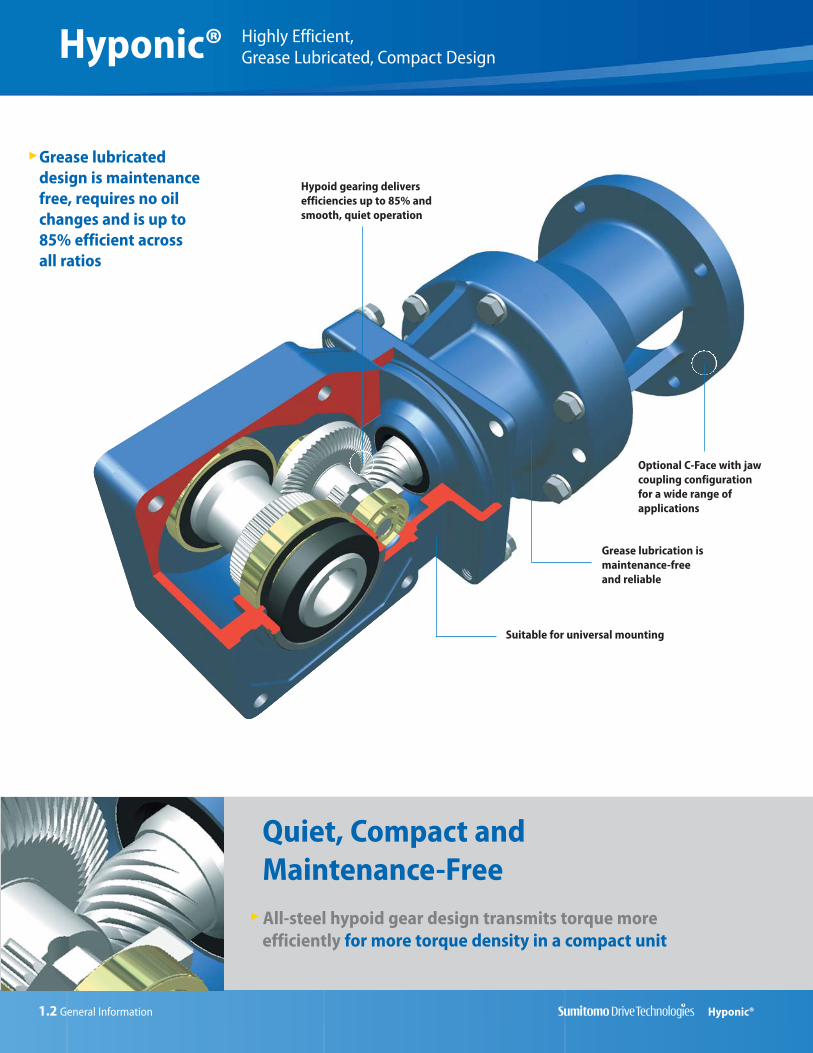
Highly Efficient, Grease Lubricated, Compact DesignHyponic®
Grease lubricateddesign is maintenancefree, requires no oilchanges and is up to85% efficient acrossall ratios
Hypoid gearing deliversefficiencies up to 85% andsmooth, quiet operation
Grease lubrication ismaintenance-free and reliable
Suitable for universal mounting
Optional C-Face with jawcoupling configuration for a wide range ofapplications
Quiet, Compact andMaintenance-FreeAll-steel hypoid gear design transmits torque moreefficiently for more torque density in a compact unit
General Information 1.3Hyponic®
Hypoid Right AngleGearmotors and Reducers
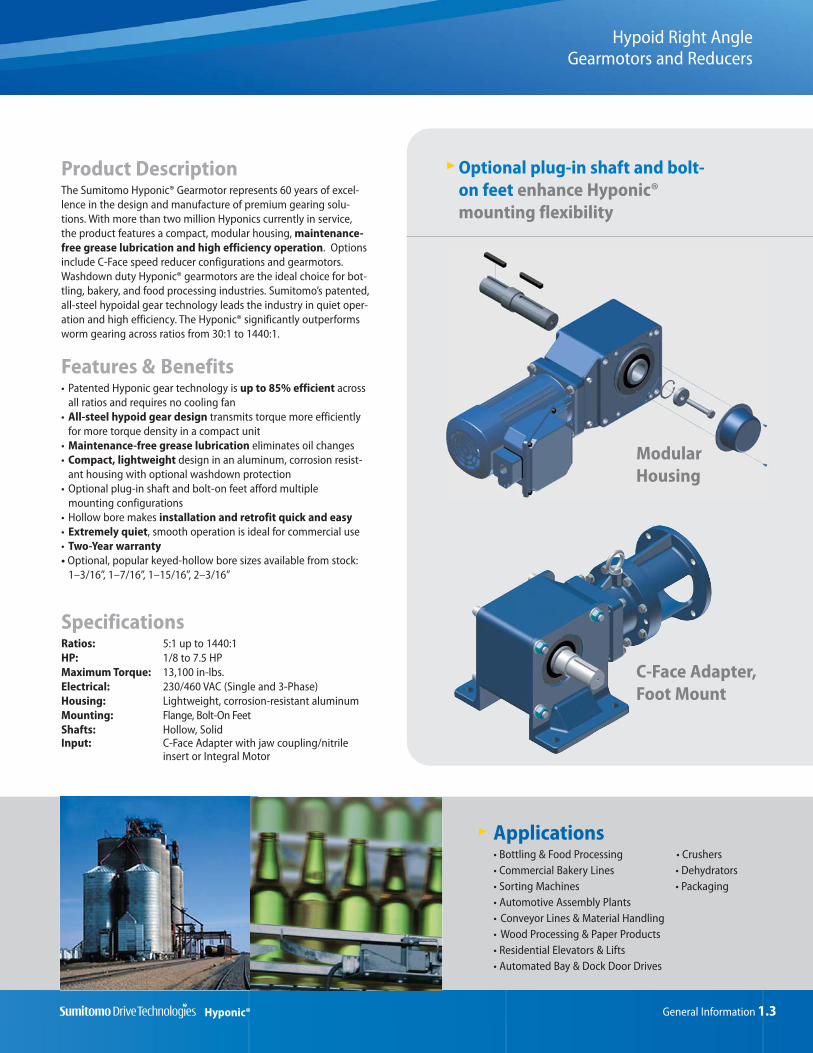
Product DescriptionThe Sumitomo Hyponic® Gearmotor represents 60 years of excel-lence in the design and manufacture of premium gearing solu-tions. With more than two million Hyponics currently in service,the product features a compact, modular housing, maintenance-free grease lubrication and high efficiency operation. Optionsinclude C-Face speed reducer configurations and gearmotors.Washdown duty Hyponic® gearmotors are the ideal choice for bot-tling, bakery, and food processing industries. Sumitomo’s patented,all-steel hypoidal gear technology leads the industry in quiet oper-ation and high efficiency. The Hyponic® significantly outperformsworm gearing across ratios from 30:1 to 1440:1.
Features & Benefits• Patented Hyponic gear technology is up to 85% efficient across
all ratios and requires no cooling fan• All-steel hypoid gear design transmits torque more efficiently
for more torque density in a compact unit• Maintenance-free grease lubrication eliminates oil changes • Compact, lightweight design in an aluminum, corrosion resist-
ant housing with optional washdown protection• Optional plug-in shaft and bolt-on feet afford multiple
mounting configurations• Hollow bore makes installation and retrofit quick and easy• Extremely quiet, smooth operation is ideal for commercial use• Two-Year warranty• Optional, popular keyed-hollow bore sizes available from stock:
1–3/16”, 1–7/16”, 1–15/16”, 2–3/16”
SpecificationsRatios: 5:1 up to 1440:1HP: 1/8 to 7.5 HPMaximum Torque: 13,100 in-lbs.Electrical: 230/460 VAC (Single and 3-Phase)Housing: Lightweight, corrosion-resistant aluminumMounting: Flange, Bolt-On FeetShafts: Hollow, SolidInput: C-Face Adapter with jaw coupling/nitrile
insert or Integral Motor
Optional plug-in shaft and bolt-on feet enhance Hyponic®mounting flexibility
C-Face Adapter,Foot Mount
ModularHousing
Applications• Bottling & Food Processing • Crushers• Commercial Bakery Lines • Dehydrators• Sorting Machines • Packaging • Automotive Assembly Plants• Conveyor Lines & Material Handling• Wood Processing & Paper Products• Residential Elevators & Lifts• Automated Bay & Dock Door Drives

1.4 General Information
Hyponic®
Hyponic®
Product Range (Standard Motor and Reducer Combinations)
1.5
3/4
1/3
Gearmotor Reduction Ratios 5 — 1440 Combinations with 1750 RPM motor
C-Face Reducer with Jaw Coupling Options
Frame Size Ratio (:1) Standard Bore*(inches)
Output Torque at1750 RPM Input (in•lb)
AvailableMotor Frames
1120 5 – 60 3/4 41 – 246 42C – 56C
1220 5 – 60 1 82.1 – 492 48C – 56C
1230 80 – 240 1 328 – 867 42C – 56C
1320 5 – 60 1 1/4 164 – 985 56C – 145TC
1330 80 – 240 1 1/4 657 – 1727 48C – 56C
1340 300 – 1440 1 1/4 1159 – 1727 42C – 56C
1420 5 – 60 1 3/8 316 – 1970 56C – 145TC
1430 80 – 240 1 3/8 1313 – 3455 56C
1440 300 – 1440 1 3/8 2318 – 3455 48C – 56C
1520 5 – 60 1 1/2 459 – 3792 56C – 184TC
1530 80 – 240 1 1/2 2627 – 6475 56C – 145TC
1531 40 – 80 1 1/2 3674 – 5056 56C – 184TC
1540 300 – 1440 1 1/2 4635 – 6475 56C
1640 300 – 1440 2 9270 – 13107 56C – 143TC
*Optional bore sizes are available
General Information 1.5
Hyponic®
Hyponic®
How do I select a Hyponic® reducer or gearmotor?Selection is based on the actual horsepower and/or torque requirements at the output shaft. The Hyponic® speed reducer has particu-larly high efficiencies over a wide range of reduction ratios, which frequently permits the use of reduced input power requirements(smaller HP motor) without sacrificing output shaft torque. The selection procedures in this catalog, Speed Reducers pages 2.2 - 2.3and Gearmotors pages 3.4 - 3.5, will guide you in choosing the most efficient reducer for your application.
What information do I need to get started in the selection process?To select the proper reducer for your application, you will need to know:
· Application: type of driven machine· Hours of operation per day· Motor horsepower (HP) and speed (RPM)· Loading Conditions· Mounting Position
If there are any special environmental factors or operation requirements, they must also be noted. This information will be importantin determining the Service Factor of your application.
What are service factors and how are they used?In general, reducers and gearmotors are rated for specific conditions and operating requirements of the application by the use ofAGMA-defined Service Factors. There are three AGMA load classifications for reducers: uniform (U), moderate shock (M), and heavyshock (H) (page 2.6) and three AGMA load classifications for gearmotors: I, II, and III (page 3.8). The Service Factors are used in the product selection process to adjust for the specific conditions and operating requirements of your application.
What do I do if my application has particularly severe operating conditions?The standard ratings for Hyponic® are based on 10-hour daily service under conditions of uniform loads (equivalent to AGMA servicefactor 1.0). By following the product selection process, you will determine and apply the Service Factors to compensate for severeoperating conditions.
How can I be sure that the reducer can withstand periodic excessive overloads?Hyponic® speed reducers provide 250% momentary intermittent shock load capacity. For applications with shock loads greater than250%, consult a Sumitomo Application Engineer.
What are the standard input speeds?In general terms, the speeds are 1750 and 1165 RPM. The selection tables in this catalog are based on 1750 RPM. The reducer selection tables show ratings at 1750, 1465, 1165, 980, 870, 720, 580, and 50 RPM.
What are the thermal limitations of the Hyponic®?The Hyponic® speed reducer, by virtue of its smooth, almost frictionless operation (unlike traditional helical gears), has a thermal rating that far exceeds its mechanical capacity and all but eliminates the conventional limitations due to heat.
What is the standard mounting of the Hyponic®?The Hyponic® is standardly supplied as a shaft mount with a keyed hollow bore. Options are available for a solid shaft with feet and a flange mounting configuration. Since the Hyponic® is grease lubricated as standard, it can be mounted in any position without modifications.
Do you supply a torque arm? At what position should it be mounted?A torque arm assembly is offered as an option. The standard torque arm assembly and standard mounting positions are shown in the Appendix on pages 5.10 - 5.12.
What is the required tolerance of the shaft to be used on the Hyponic®? Shaft tolerances will depend on the type of load and shock load of the application. Shaft tolerance recommendations are included in the Appendix on page 5.9
What is the rotation of the Hyponic shaft?The direction of shaft rotation on Hyponic reducers varies according to frame size and ratio. Please refer to page 5.3 in the Appendixfor specific data on the shaft rotation of various models.
FAQs
1.6 General Information
Hyponic®
Hyponic®
FAQs continued
What C-Face sizes are available for the Hyponic®?C-Face sizes are based on the Hyponic® size and ratio of the selection. The C-Face Reducer with Jaw Coupling Options table on page1.4 lists available C-Face frame sizes.
What should be considered when connecting to the Hyponic® shaft?When mounting a pulley, sprocket, or sheave, mount as close to the unit housing as possible; never mount beyond the midpoint of theshaft projection to avoid undue bearing load and shaft deflection. Never overtighten belts or chains. Careful and accurate installationis essential for best results and trouble-free operation. Before installing, the shafts should be checked to make sure they are paralleland level. After mounting, alignment should be checked with a string or straight edge held against the sides of the sprocket or pulleybase. Couplings should be properly aligned to the limits specified by the manufacturer. Check alignment prior to initial startup oncoupled Hyponic® units.
Should overhung load and thrust load be considered when making a selection?Yes, loads imposed on the slow speed shaft will vary according to the method used to connect the shaft to the driven machine.Frequently, in addition to the torsional forces, radial (overhung) and thrust loads are applied to the slow speed shaft at the same time.For example, coupling connections normally involve torsional forces only. However, when power is transmitted through spur gears,belts, pulleys, or chains, both torsional and radial forces may be present. When driving through helical or bevel gears, all three condi-tions (torsional, radial, and thrust load) may be referred to the reducer shaft. The slow speed shaft and bearings must have sufficientstrength to withstand these loads, and it is necessary to determine the allowable limits for each condition. Page 5.5 in the Appendixexplains how to calculate the overhung load (radial) applied to the output shaft.
What is meant by load centering?The reducer’s radial load capacities are calculated at the midpoint of the slow speed shaft extension. Radial load capacities decrease ifthe center of the load is moved farther from the reducer and the values obtained must be adjusted accordingly. Refer to page 5.5 inthe Appendix for load location factors.

General Information 1.7
Hyponic®
Hyponic®
Standard Specifications
Shaft RotationThe direction of shaft rotation on Hyponic reducers varies according to frame size and ratio. Please referto page 5.3 in the Appendix for specific data on the shaft rotation of various models.
Input SpeedsIn general terms, the speeds are 1750 and 1165 RPM. The selection tables in this catalog are based on1750 RPM. The reducer selection tables show ratings at 1750, 1465, 1165, 980, 870, 720, 580, and 50 RPM.
Thermal CapacityThe Hyponic® speed reducer, by virtue of its smooth, almost frictionless operation (unlike traditional helicalgears), has a thermal rating that far exceeds its mechanical capacity and all but eliminates the conventionallimitations due to heat.
Standard Specifications Standard Specifications with Built-In Brake
3-Phase Capacity Range: 1/8 HP ~ 7.5 HP, 4P 1/8 HP ~ 7.5 HP, 4P: FB Brake
Integral MotorEnclosure: Totally enclosed fan cooled type Totally enclosed fan cooled type
(1/8 HP, 4P Totally enclosed non ventilated) (1/8 HP, 4P Totally enclosed non ventilated)
Power Supply: 230/460 Volts, 60 Hz 230/460 Volts, 60 Hz575 Volts, 60 Hz 575 Volts, 60 Hz
Insulation: 1/8 ~ 1/2 HP: Class F 1/8 ~ 1/2 HP: Class F, Brake: Class F3/4 ~ 7.5 HP: Class F 3/4 ~ 7.5 HP: Class F, Brake: Class F
Time Rating Continuous Continuous
Single-Phase Capacity Range: 1/8 HP ~ 1/2 HP, 4P 1/8 HP ~ 1/2 HP, 4P: FB Brake
Integral MotorEnclosure: Totally enclosed fan cooled type Totally enclosed fan cooled type
Power Supply: 115/230 Volts, 60 Hz 115/230 Volts, 60 Hz
Insulation: Class F Class F, Brake: Class F
Time Rating Continuous Continuous
Starting Method Capacitor start and run Capacitor start and run
Inverter Duty Capacity Range: 1/8 HP ~ 5 HP, 4P 1/8 HP ~ 5 HP, 4P: FB Brake
Integral MotorEnclosure: Totally enclosed fan cooled type Totally enclosed fan cooled type
Power Supply: 230/460 Volts, 60 Hz 230/460 Volts, 60 Hz
Insulation: Class F Class F, Brake: Class F
Time Rating Continuous (6-60Hz constant torque) Continuous (6-60Hz constant torque)
Reducer Reduction: Combination of hypoid gear input and involute gear output.
Lubrication: Grease lubricated; filled with special high-grade grease prior to shipment.
Seals: Nitrile material, triple lipped output seals.
Material: Casing: aluminum alloy; Gear: chrome-molybdenum steel
Paint Color: Blue, Muenters color number 6.5PB 3.6/8.2
Bearings: Ball bearings on input and output.
Ambient Installation Location: Indoors (Minimal dust and humidity)
ConditionsAmbient Temperature: 14°~104° F (-10º ~ 40º C)
Ambient Humidity: Under 85%
Elevation: Under 3,281 ft. (1000 meters)
Atmosphere: Well ventilated location, free of corrosive gases, explosive gases, vapors and dust.

1.8 General Information
Hyponic®
Hyponic®
This page intentionally left blank.

Speed Reducers 2.1Hyponic®
Speed Reducers2
How
toSe
lect
SpeedReducers
Speed Reducers
Hollow Shaft Type
Speed Reducers
2.2 Speed Reducers
How
toSe
lect
Hyponic®
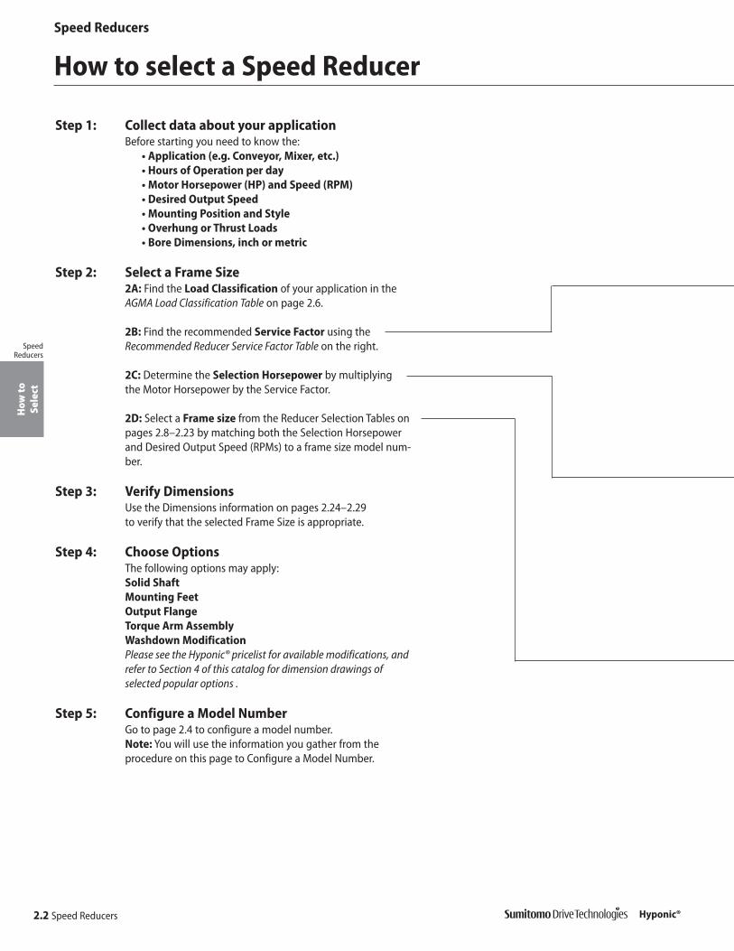
How to select a Speed Reducer
Step 1: Collect data about your applicationBefore starting you need to know the:
• Application (e.g. Conveyor, Mixer, etc.)• Hours of Operation per day• Motor Horsepower (HP) and Speed (RPM)• Desired Output Speed• Mounting Position and Style• Overhung or Thrust Loads• Bore Dimensions, inch or metric
Step 2: Select a Frame Size2A: Find the Load Classification of your application in theAGMA Load Classification Table on page 2.6.
2B: Find the recommended Service Factor using theRecommended Reducer Service Factor Table on the right.
2C: Determine the Selection Horsepower by multiplyingthe Motor Horsepower by the Service Factor.
2D: Select a Frame size from the Reducer Selection Tables onpages 2.8–2.23 by matching both the Selection Horsepowerand Desired Output Speed (RPMs) to a frame size model num-ber.
Step 3: Verify DimensionsUse the Dimensions information on pages 2.24–2.29to verify that the selected Frame Size is appropriate.
Step 4: Choose OptionsThe following options may apply:Solid ShaftMounting FeetOutput FlangeTorque Arm AssemblyWashdown ModificationPlease see the Hyponic® pricelist for available modifications, andrefer to Section 4 of this catalog for dimension drawings of selected popular options .
Step 5: Configure a Model NumberGo to page 2.4 to configure a model number.Note: You will use the information you gather from the procedure on this page to Configure a Model Number.
SpeedReducers

Select aFrame Size Match your OUTPUT RPM (or RATIO)...
...to find yourFRAME SIZE
1
3...to yourSELECTION HP...2
Speed Reducers
Speed Reducers 2.3
How
toSe
lect
Hyponic®
Recommended ReducerService Factors[1] AGMA Load Classifications
Uniform (U) Moderate Shock (M) Heavy Shock (H)
1/2 hr. per day (Occasional) 0.50[2] 0.80[2] 1.25
Duration of Service 3 hrs. per day (Intermittent) 0.80* 1.00 1.50
Up to 10 hrs. per day 1.00 1.25 1.75
24 hrs. per day 1.20 1.50 2.00
Notes: [1] Please consult factory for additional service factors on applications with more than 10 starts/stops
per hour, or when reflected load inertia >0.3.
[2] Maximum momentary or starting load must not exceed 300% of gear reducer rating (rating meaning service factor of 1.0). Time specified for occasional and intermittent service refers to total operating time per day.
DetermineSelectionHorsepower (HP)
Motor HP X Service Factor = Selection HP
Example: 10 Motor HP X 1.25 Service Factor = 12.5 Selection HP
For special circum-stances affectingFrame Size selectionsuch as:
• Overhung Load• Shock Loading
Consult Appendix,pages 5.5–5.6.
If Overhung Load ispresent, it must be
checked against thecapacity of
the selection.
SpeedReducers
motor inertia

Configure a Model NumberN
omen
clat
ure
SpeedReducers
Speed Reducers
Hyponic® 2.4 Speed Reducers
R N Y J 20J11 2 2 0
Hyponic product code (always “R”)
Output shaft orientation
Mounting style
Input connection
Modification (Special feature)
Frame size
Optional specification (as required)
Ratio
Output shaft direction (shafted model only)
Input Connection
Include the following information when ordering:
• Motor Specification (230/460 VAC 60 Hz is supplied, unless otherwise specified)
• NEMA frame size for C-face adaptor with jaw coupling
• Bushing Bore size (must be supplied)
• Optional conduit box positions must be specified, otherwise Y1 is supplied.
--
Input Connection Prefix
C-Face Adapter with jaw coupling J
Motor JM
-
Shaft specification
Y
Output Shaft Orientation
Type Prefix
Universal Direction(Maintenance Free)
N
Mounting Style
Type Prefix
Shaft Mount (Hollow Shaft) Y
Flange (Solid Shaft) F
Foot (Solid Shaft) H
Modification
Prefix
Special S
Standard
Frame Size
1120 14301220 14401230 15201320 15301330 15311340 15401420 1640
Output Shaft Direction (shafted model only)
Direction (when viewed from motor end) Suffix
Projects to Left Side L
Projects to Right Side R
Projects to Both Sides T

Speed Reducers
Nom
encl
atur
e
SpeedReducers
Hyponic®
Nomenclature
Nomenclature Example:
RNYJ – 1220Y – J1 – 20 R – Hyponic® 1220 – Frame Size
N – Universal Mount Y – Inch Shaft Specification
Y – Shaft Mount (Hollow Shaft) J1 – Bolt-on Feet, Bottom
J – C-Face Input 20 – Ratio
Speed Reducers 2.5
Optional Specifications (as required)
Nominal Total Ratio
Shaft Specifications
Input Shaft
Output ShaftSuffix
Hollow Solid
mm Key (mm) Key (mm)
Inch Key (Inch) Key (Inch) Y
5 20 60 200 600
7 25 80 240 720
10 30 100 300 900
12 40 120 360 1200
15 50 150 480 1440
Specification Suffix
Hollow Bore Options
Extended Flange (for motor clearance)
Left (viewed from motor end) F1
Right (viewed from motor end) G1
Solid Shaft Options
Plug-in Shaft X1
Plug-in Shaft with Bolt-on Feet
Bottom J1
Opposite from Motor S1
Top M1
Plug-in Shaft with Extended Flange(for motor clearance)
Left (viewed from motor end) P1
Right (viewed from motor end) Q1
F1 G1
J1
X1
S1 M1
P1 Q1

Speed Reducers
2.6 Speed Reducers
AG
MA
Table
s
SpeedReducers
Hyponic®
AGMA Load Classifications
AgitatorsPure liquids . . . . . . . . . . . . . . . . . . . . . . . . . . . ULiquids and solids . . . . . . . . . . . . . . . . . . . . . . MVariable-density liquids . . . . . . . . . . . . . . . . . . M
BlowersCentrifugal . . . . . . . . . . . . . . . . . . . . . . . . . . . . ULobe . . . . . . . . . . . . . . . . . . . . . . . . . . . . . . . . . MVane . . . . . . . . . . . . . . . . . . . . . . . . . . . . . . . . . U
Brewing and DistillingBottling machinery . . . . . . . . . . . . . . . . . . . . . . UBrew kettles, cont. duty . . . . . . . . . . . . . . . . . . UCookers, cont. duty . . . . . . . . . . . . . . . . . . . . . UMash tubs, cont. duty . . . . . . . . . . . . . . . . . . . UScale hopper, frequent starts . . . . . . . . . . . . . M
Can Filling Machines . . . . . . . . . . . . . . . . . . . . . . . UCane Knives . . . . . . . . . . . . . . . . . . . . . . . . . . . . . . MCar Dumpers . . . . . . . . . . . . . . . . . . . . . . . . . . . . . . HCar Pullers . . . . . . . . . . . . . . . . . . . . . . . . . . . . . . . MClarifiers . . . . . . . . . . . . . . . . . . . . . . . . . . . . . . . . . UClassifiers . . . . . . . . . . . . . . . . . . . . . . . . . . . . . . . . MClay Working Machinery
Brick press . . . . . . . . . . . . . . . . . . . . . . . . . . . . HBriquette machine . . . . . . . . . . . . . . . . . . . . . . HClay working machinery . . . . . . . . . . . . . . . . . MPug mill . . . . . . . . . . . . . . . . . . . . . . . . . . . . . . M
CompressorsCentrifugal . . . . . . . . . . . . . . . . . . . . . . . . . . . . ULobe . . . . . . . . . . . . . . . . . . . . . . . . . . . . . . . . . MReciprocating, multi-cylinder . . . . . . . . . . . . . . MReciprocating, single-cylinder . . . . . . . . . . . . . H
Conveyors — Uniformly Loaded or FedApron . . . . . . . . . . . . . . . . . . . . . . . . . . . . . . . . UAssembly . . . . . . . . . . . . . . . . . . . . . . . . . . . . . UBelt . . . . . . . . . . . . . . . . . . . . . . . . . . . . . . . . . . UBucket . . . . . . . . . . . . . . . . . . . . . . . . . . . . . . . UChain . . . . . . . . . . . . . . . . . . . . . . . . . . . . . . . . UFlight . . . . . . . . . . . . . . . . . . . . . . . . . . . . . . . . . UOven . . . . . . . . . . . . . . . . . . . . . . . . . . . . . . . . . UScrew . . . . . . . . . . . . . . . . . . . . . . . . . . . . . . . . U
Conveyors — Heavy Duty, Not Uniformly FedApron . . . . . . . . . . . . . . . . . . . . . . . . . . . . . . . . MAssembly . . . . . . . . . . . . . . . . . . . . . . . . . . . . . MBelt . . . . . . . . . . . . . . . . . . . . . . . . . . . . . . . . . . MBucket . . . . . . . . . . . . . . . . . . . . . . . . . . . . . . . MChain . . . . . . . . . . . . . . . . . . . . . . . . . . . . . . . . MFlight . . . . . . . . . . . . . . . . . . . . . . . . . . . . . . . . MLive roll oven . . . . . . . . . . . . . . . . . . . . . . . . . . MReciprocating . . . . . . . . . . . . . . . . . . . . . . . . . . HScrew . . . . . . . . . . . . . . . . . . . . . . . . . . . . . . . . MShaker . . . . . . . . . . . . . . . . . . . . . . . . . . . . . . . H
Cranes (Except for Dry Dock Cranes)Main hoists . . . . . . . . . . . . . . . . . . . . . . . . . . . . UBridge travel . . . . . . . . . . . . . . . . . . . . . . . . . . . STrolley travel . . . . . . . . . . . . . . . . . . . . . . . . . . . S
CrusherOre . . . . . . . . . . . . . . . . . . . . . . . . . . . . . . . . . . HStone . . . . . . . . . . . . . . . . . . . . . . . . . . . . . . . . HSugar . . . . . . . . . . . . . . . . . . . . . . . . . . . . . . . . M
DredgesCable reels . . . . . . . . . . . . . . . . . . . . . . . . . . . . MConveyors . . . . . . . . . . . . . . . . . . . . . . . . . . . . MCutter head drives . . . . . . . . . . . . . . . . . . . . . . HJig drives . . . . . . . . . . . . . . . . . . . . . . . . . . . . . HManeuvering winches . . . . . . . . . . . . . . . . . . . MPumps . . . . . . . . . . . . . . . . . . . . . . . . . . . . . . . MScreen drive . . . . . . . . . . . . . . . . . . . . . . . . . . . HStackers . . . . . . . . . . . . . . . . . . . . . . . . . . . . . . MUtility winches . . . . . . . . . . . . . . . . . . . . . . . . . M
Dry Dock Cranes . . . . . . . . . . . . . . . . . . . . . . . . . . . SElevators
Bucket, uniform load . . . . . . . . . . . . . . . . . . . . UBucket, heavy load . . . . . . . . . . . . . . . . . . . . . MBucket, cont. . . . . . . . . . . . . . . . . . . . . . . . . . . UCentrifugal discharge . . . . . . . . . . . . . . . . . . . . UEscalators . . . . . . . . . . . . . . . . . . . . . . . . . . . . . UFreight . . . . . . . . . . . . . . . . . . . . . . . . . . . . . . . MGravity discharge . . . . . . . . . . . . . . . . . . . . . . . UMan lifts . . . . . . . . . . . . . . . . . . . . . . . . . . . . . . SPassenger . . . . . . . . . . . . . . . . . . . . . . . . . . . . . S
Extruders (Plastics)Blow molders . . . . . . . . . . . . . . . . . . . . . . . . . . MCoating . . . . . . . . . . . . . . . . . . . . . . . . . . . . . . . UFilm . . . . . . . . . . . . . . . . . . . . . . . . . . . . . . . . . . UPipe . . . . . . . . . . . . . . . . . . . . . . . . . . . . . . . . . UPre-plasticizers . . . . . . . . . . . . . . . . . . . . . . . . MRods . . . . . . . . . . . . . . . . . . . . . . . . . . . . . . . . . USheet . . . . . . . . . . . . . . . . . . . . . . . . . . . . . . . . UTubing . . . . . . . . . . . . . . . . . . . . . . . . . . . . . . . . U
FansCentrifugal . . . . . . . . . . . . . . . . . . . . . . . . . . . . UCooling towers . . . . . . . . . . . . . . . . . . . . . . . . . SForced draft . . . . . . . . . . . . . . . . . . . . . . . . . . . SInduced draft . . . . . . . . . . . . . . . . . . . . . . . . . . MLarge (mine, etc.) . . . . . . . . . . . . . . . . . . . . . . . M
Large (industrial) . . . . . . . . . . . . . . . . . . . . . . . MLight (small diameter) . . . . . . . . . . . . . . . . . . . . U
FeedersApron . . . . . . . . . . . . . . . . . . . . . . . . . . . . . . . . MBelt . . . . . . . . . . . . . . . . . . . . . . . . . . . . . . . . . . MDisc . . . . . . . . . . . . . . . . . . . . . . . . . . . . . . . . . UReciprocating . . . . . . . . . . . . . . . . . . . . . . . . . . HScrew . . . . . . . . . . . . . . . . . . . . . . . . . . . . . . . . M
Food IndustryBeet slicer . . . . . . . . . . . . . . . . . . . . . . . . . . . . MCereal cooker . . . . . . . . . . . . . . . . . . . . . . . . . . UDough mixer . . . . . . . . . . . . . . . . . . . . . . . . . . MMeat grinders . . . . . . . . . . . . . . . . . . . . . . . . . . M
Generators (Not Welding) . . . . . . . . . . . . . . . . . . . . UHammer Mills . . . . . . . . . . . . . . . . . . . . . . . . . . . . . HHoists
Heavy duty . . . . . . . . . . . . . . . . . . . . . . . . . . . . HMedium duty . . . . . . . . . . . . . . . . . . . . . . . . . . MSkip . . . . . . . . . . . . . . . . . . . . . . . . . . . . . . . . . M
Laundry Washers — Reversing . . . . . . . . . . . . . . . MLaundry Tumblers . . . . . . . . . . . . . . . . . . . . . . . . . . MLine Shaft
Drive processing equipment . . . . . . . . . . . . . . MLight . . . . . . . . . . . . . . . . . . . . . . . . . . . . . . . . . UOther line shafts . . . . . . . . . . . . . . . . . . . . . . . . U
Lumber IndustryBarkers — hydraulic and mechanical . . . . . . . SBurner conveyor . . . . . . . . . . . . . . . . . . . . . . . M
Chain Saw and Drag Saw . . . . . . . . . . . . . . . . . . . . HChain transfer . . . . . . . . . . . . . . . . . . . . . . . . . . HCraneway transfer . . . . . . . . . . . . . . . . . . . . . . HDe-barking drum . . . . . . . . . . . . . . . . . . . . . . . HEdger feed . . . . . . . . . . . . . . . . . . . . . . . . . . . . HGang feed . . . . . . . . . . . . . . . . . . . . . . . . . . . . MGeen chain . . . . . . . . . . . . . . . . . . . . . . . . . . . . MLive rolls . . . . . . . . . . . . . . . . . . . . . . . . . . . . . . HLog haul-lockline . . . . . . . . . . . . . . . . . . . . . . . HLog turning device . . . . . . . . . . . . . . . . . . . . . . HMain log conveyor . . . . . . . . . . . . . . . . . . . . . . HOff bearing rolls . . . . . . . . . . . . . . . . . . . . . . . . MPlaner feed chains . . . . . . . . . . . . . . . . . . . . . . MPlaner floor chains . . . . . . . . . . . . . . . . . . . . . . MPlaner tilting hoist . . . . . . . . . . . . . . . . . . . . . . MRe-saw merry-go-round conveyor . . . . . . . . . MRoll cases . . . . . . . . . . . . . . . . . . . . . . . . . . . . . HSlab conveyor . . . . . . . . . . . . . . . . . . . . . . . . . HSmall waste-conveyor-belt . . . . . . . . . . . . . . . USmall waste-conveyor-chain . . . . . . . . . . . . . . MSorting table . . . . . . . . . . . . . . . . . . . . . . . . . . MTipple hoist conveyor . . . . . . . . . . . . . . . . . . . MTipple hoist drive . . . . . . . . . . . . . . . . . . . . . . . MTransfer conveyors . . . . . . . . . . . . . . . . . . . . . MTransfer rolls . . . . . . . . . . . . . . . . . . . . . . . . . . MTray drive . . . . . . . . . . . . . . . . . . . . . . . . . . . . . MTrimmer feed . . . . . . . . . . . . . . . . . . . . . . . . . . MWaste conveyor . . . . . . . . . . . . . . . . . . . . . . . . M
Machine ToolsBending roll . . . . . . . . . . . . . . . . . . . . . . . . . . . MNotching press, belt driven . . . . . . . . . . . . . . . SPlate planer . . . . . . . . . . . . . . . . . . . . . . . . . . . HPunch press, gear driven . . . . . . . . . . . . . . . . . HTapping machine . . . . . . . . . . . . . . . . . . . . . . . HOther machine tools
Main drives . . . . . . . . . . . . . . . . . . . . . . . . MAuxiliary drives . . . . . . . . . . . . . . . . . . . . . . U
Metal MillsDraw bench carriage and main drive . . . . . . . MForming machines . . . . . . . . . . . . . . . . . . . . . . HPinch, dryer and scrubber rolls, reversing . . . . SSlitters . . . . . . . . . . . . . . . . . . . . . . . . . . . . . . . MTable conveyors, nonreversing
Group drives . . . . . . . . . . . . . . . . . . . . . . . MIndividual drives . . . . . . . . . . . . . . . . . . . . . H
Table conveyors, reversing . . . . . . . . . . . . . . . . SWire drawing and flattening machine . . . . . . . MWire winding machine . . . . . . . . . . . . . . . . . . . M
Mills, Rotary TypeBall . . . . . . . . . . . . . . . . . . . . . . . . . . . . . . . . . . MCement kilns . . . . . . . . . . . . . . . . . . . . . . . . . . MDryers and coolers . . . . . . . . . . . . . . . . . . . . . MKilns . . . . . . . . . . . . . . . . . . . . . . . . . . . . . . . . . MPebble . . . . . . . . . . . . . . . . . . . . . . . . . . . . . . . MRod, plain and wedge bar . . . . . . . . . . . . . . . . MTumbling barrels . . . . . . . . . . . . . . . . . . . . . . . . H
MixersConcrete mixers, cont. . . . . . . . . . . . . . . . . . . MConcrete mixers, intermittent . . . . . . . . . . . . . MConstant density . . . . . . . . . . . . . . . . . . . . . . . UVariable density . . . . . . . . . . . . . . . . . . . . . . . . M
Oil IndustryChillers . . . . . . . . . . . . . . . . . . . . . . . . . . . . . . . MOil well pumps . . . . . . . . . . . . . . . . . . . . . . . . . SParaffin filter press . . . . . . . . . . . . . . . . . . . . . . MRotary kilns . . . . . . . . . . . . . . . . . . . . . . . . . . . M
Paper MillsAgitators (mixers) . . . . . . . . . . . . . . . . . . . . . . . MBarker, hydraulic . . . . . . . . . . . . . . . . . . . . . . . MBarker, mechanical . . . . . . . . . . . . . . . . . . . . . MBarking drum . . . . . . . . . . . . . . . . . . . . . . . . . . HBeater and pulper . . . . . . . . . . . . . . . . . . . . . . MBleacher . . . . . . . . . . . . . . . . . . . . . . . . . . . . . . UCalenders . . . . . . . . . . . . . . . . . . . . . . . . . . . . . MCalenders, super . . . . . . . . . . . . . . . . . . . . . . . HConverting machine (except cutters, platers) . MConveyors . . . . . . . . . . . . . . . . . . . . . . . . . . . . UCouch . . . . . . . . . . . . . . . . . . . . . . . . . . . . . . . MCutters, platers . . . . . . . . . . . . . . . . . . . . . . . . . HCylinders . . . . . . . . . . . . . . . . . . . . . . . . . . . . . MDryers . . . . . . . . . . . . . . . . . . . . . . . . . . . . . . . MFelt stretcher . . . . . . . . . . . . . . . . . . . . . . . . . . MFelt whipper . . . . . . . . . . . . . . . . . . . . . . . . . . . HJordans . . . . . . . . . . . . . . . . . . . . . . . . . . . . . . . HLog haul . . . . . . . . . . . . . . . . . . . . . . . . . . . . . . HPresses . . . . . . . . . . . . . . . . . . . . . . . . . . . . . . . UPulp machine reel . . . . . . . . . . . . . . . . . . . . . . MStock chest . . . . . . . . . . . . . . . . . . . . . . . . . . . MSuction roll . . . . . . . . . . . . . . . . . . . . . . . . . . . . UWashers and thickeners . . . . . . . . . . . . . . . . . MWinders . . . . . . . . . . . . . . . . . . . . . . . . . . . . . . U
Printing Presses . . . . . . . . . . . . . . . . . . . . . . . . . . . SPullers, Barge Haul . . . . . . . . . . . . . . . . . . . . . . . . . HPumps
Centrifugal . . . . . . . . . . . . . . . . . . . . . . . . . . . . UProportioning . . . . . . . . . . . . . . . . . . . . . . . . . . MReciprocating
Single acting, 3 or more cylinders . . . . . . MDouble acting, 2 or more cylinders . . . . . . M
Rotary-gear type . . . . . . . . . . . . . . . . . . . . . . . URubber and Plastics Industries
Crackers . . . . . . . . . . . . . . . . . . . . . . . . . . . . . . HLaboratory equipment . . . . . . . . . . . . . . . . . . . MMixing mills . . . . . . . . . . . . . . . . . . . . . . . . . . . HRefiners . . . . . . . . . . . . . . . . . . . . . . . . . . . . . . MRubber calenders . . . . . . . . . . . . . . . . . . . . . . MRubber mill (2 on line) . . . . . . . . . . . . . . . . . . . MRubber mill (3 on line) . . . . . . . . . . . . . . . . . . . USheeter . . . . . . . . . . . . . . . . . . . . . . . . . . . . . . MTire building machines . . . . . . . . . . . . . . . . . . . STire and tube press openers . . . . . . . . . . . . . . STubers and strainers . . . . . . . . . . . . . . . . . . . . MWarming mills . . . . . . . . . . . . . . . . . . . . . . . . . M
Sand Muller . . . . . . . . . . . . . . . . . . . . . . . . . . . . . . MScreens
Air washing . . . . . . . . . . . . . . . . . . . . . . . . . . . . URotary, stone or gravel . . . . . . . . . . . . . . . . . . MTraveling water intake . . . . . . . . . . . . . . . . . . . U
Sewage Disposal EquipmentBar screens . . . . . . . . . . . . . . . . . . . . . . . . . . . UChemical fenders . . . . . . . . . . . . . . . . . . . . . . . UCollectors, circuline or straightline . . . . . . . . . . UDewatering screens . . . . . . . . . . . . . . . . . . . . . MGrit collectors . . . . . . . . . . . . . . . . . . . . . . . . . . UScum breakers . . . . . . . . . . . . . . . . . . . . . . . . . MSlow or rapid mixers . . . . . . . . . . . . . . . . . . . . MSludge collectors . . . . . . . . . . . . . . . . . . . . . . . UThickeners . . . . . . . . . . . . . . . . . . . . . . . . . . . . MVacuum filters . . . . . . . . . . . . . . . . . . . . . . . . . M
Slab Pushers . . . . . . . . . . . . . . . . . . . . . . . . . . . . . MSteering Gear . . . . . . . . . . . . . . . . . . . . . . . . . . . . . SStokers . . . . . . . . . . . . . . . . . . . . . . . . . . . . . . . . . . USugar Industry
Cane knives . . . . . . . . . . . . . . . . . . . . . . . . . . . MCrushers . . . . . . . . . . . . . . . . . . . . . . . . . . . . . MMills . . . . . . . . . . . . . . . . . . . . . . . . . . . . . . . . . H
Textile IndustryBatchers . . . . . . . . . . . . . . . . . . . . . . . . . . . . . . MCalenders . . . . . . . . . . . . . . . . . . . . . . . . . . . . . MCards . . . . . . . . . . . . . . . . . . . . . . . . . . . . . . . . MDry cans . . . . . . . . . . . . . . . . . . . . . . . . . . . . . . MDryers . . . . . . . . . . . . . . . . . . . . . . . . . . . . . . . MDyeing machinery . . . . . . . . . . . . . . . . . . . . . . MKnitting machines . . . . . . . . . . . . . . . . . . . . . . . SLooms . . . . . . . . . . . . . . . . . . . . . . . . . . . . . . . MMangles . . . . . . . . . . . . . . . . . . . . . . . . . . . . . . MNappers . . . . . . . . . . . . . . . . . . . . . . . . . . . . . . MPads . . . . . . . . . . . . . . . . . . . . . . . . . . . . . . . . . MRange drives . . . . . . . . . . . . . . . . . . . . . . . . . . . SSlashers . . . . . . . . . . . . . . . . . . . . . . . . . . . . . . MSoapers . . . . . . . . . . . . . . . . . . . . . . . . . . . . . . MSpinners . . . . . . . . . . . . . . . . . . . . . . . . . . . . . . MTenter frames . . . . . . . . . . . . . . . . . . . . . . . . . . MWashers . . . . . . . . . . . . . . . . . . . . . . . . . . . . . . MWinders . . . . . . . . . . . . . . . . . . . . . . . . . . . . . . M
Windlass . . . . . . . . . . . . . . . . . . . . . . . . . . . . . . . . . S
TYPE OF TYPE OFAPPLICATION LOAD
TYPE OF TYPE OFAPPLICATION LOAD
TYPE OF TYPE OFAPPLICATION LOAD
U = Uniform Load H = Heavy ShockM = Moderate Shock S = Contact Sumitomo

This page intentionally left blank.
Speed Reducers 2.7Hyponic®

Speed Reducers
2.8 Speed Reducers - 1750 RPM Selection Tables
Sele
ctio
nTa
bles
SpeedReducers
Hyponic®
Frame Size Selection Tables 60 Hz
1750 RPM Dimensions: Frame Size Page Frame Size Page1100 2.24 1400 2.271200 2.25 1500 2.281300 2.26 1600 2.29
Output RPM 350 250 175 146 117 87.5 70.0 58.3 43.8 35.0 29.2 21.9 17.5 FrameSizeRatio 5 7 10 12 15 20 25 30 40 50 60 80 100
Input HP 0.268 0.268 0.268 0.268 0.268 0.268 0.268 0.268 0.134 0.134 0.134 – –
Output Torque in•lbs 41.0 57.5 82.1 98.5 123 164 205 246 164 205 246 – – 1120
Overhung Load lbs 132 143 165 176 187 209 220 231 254 276 287 – –
Input HP 0.536 0.536 0.536 0.536 0.536 0.536 0.536 0.536 0.268 0.268 0.268 – –
Output Torque in•lbs 82.1 115 164 197 246 328 410 492 328 410 492 – – 1220
Overhung Load lbs 187 209 231 243 265 298 309 331 353 375 386 – –
Input HP – – – – – – – – – – – 0.134 0.134
Output Torque in•lbs – – – – – – – – – – – 328 410 1230
Overhung Load lbs – – – – – – – – – – – 397 397
Input HP 1.07 1.07 1.07 1.07 1.07 1.07 1.07 1.07 0.536 0.536 0.536 – –
Output Torque in•lbs 164 230 328 394 492 657 821 985 657 821 985 – – 1320
Overhung Load lbs 309 353 386 408 441 485 507 529 573 617 639 – –
Input HP – – – – – – – – – – – 0.268 0.268
Output Torque in•lbs – – – – – – – – – – – 657 821 1330
Overhung Load lbs – – – – – – – – – – – 661 683
Input HP – – – – – – – – – – – – –
Output Torque in•lbs – – – – – – – – – – – – – 1340
Overhung Load lbs – – – – – – – – – – – – –
Input HP 2.06 2.06 2.06 2.06 2.06 2.06 2.06 2.06 1.07 1.07 1.07 – –
Output Torque in•lbs 316 442 632 758 948 1260 1580 1900 1310 1640 1970 – – 1420
Overhung Load lbs 463 518 584 617 661 716 761 805 860 904 937 – –
Input HP – – – – – – – – – – – 0.536 0.536
Output Torque in•lbs – – – – – – – – – – – 1310 1640 1430
Overhung Load lbs – – – – – – – – – – – 959 981
Input HP – – – – – – – – – – – – –
Output Torque in•lbs – – – – – – – – – – – – – 1440
Overhung Load lbs – – – – – – – – – – – – –
Input HP 3.00 3.00 3.00 3.00 3.00 3.00 3.00 3.00 2.06 2.06 2.06 – –
Output Torque in•lbs 459 643 918 1100 1380 1840 2300 2760 2530 3160 3790 – – 1520
Overhung Load lbs 661 750 838 893 948 1040 1100 1160 1250 1310 1360 – –
Input HP – – – – – – – – – – – 1.07 1.07
Output Torque in•lbs – – – – – – – – – – – 2630 3280 1530
Overhung Load lbs – – – – – – – – – – – 1380 1400
Input HP – – – – – – – – 3.00 3.00 3.00 2.06 –
Output Torque in•lbs – – – – – – – – 3670 4590 5510 5060 – 1531
Overhung Load lbs – – – – – – – – 1250 1310 1360 1380 –
Input HP – – – – – – – – – – – – –
Output Torque in•lbs – – – – – – – – – – – – – 1540
Overhung Load lbs – – – – – – – – – – – – –
Input HP – – – – – – – – – – – – –
Output Torque in•lbs – – – – – – – – – – – – – 1640
Overhung Load lbs – – – – – – – – – – – – –

Speed Reducers
Speed Reducers - 1750 RPM Selection Tables 2.9
Sele
ctio
nTa
bles
SpeedReducers
Hyponic®
60 Hz Frame Size Selection Tables1750 RPMDimensions: Frame Size Page Frame Size Page
1100 2.24 1400 2.271200 2.25 1500 2.281300 2.26 1600 2.29
Output RPM 14.6 11.7 8.75 7.29 5.83 4.86 3.65 2.92 2.43 1.94 1.46 1.22 FrameSizeRatio 120 150 200 240 300 360 480 600 720 900 1200 1440
Input HP – – – – – – – – – – – –
Output Torque in•lbs – – – – – – – – – – – – 1120
Overhung Load lbs – – – – – – – – – – – –
Input HP – – – – – – – – – – – –
Output Torque in•lbs – – – – – – – – – – – – 1220
Overhung Load lbs – – – – – – – – – – – –
Input HP 0.134 0.134 0.134 0.118 – – – – – – – –
Output Torque in•lbs 492 616 821 868 – – – – – – – – 1230
Overhung Load lbs 408 408 408 408 – – – – – – – –
Input HP – – – – – – – – – – – –
Output Torque in•lbs – – – – – – – – – – – – 1320
Overhung Load lbs – – – – – – – – – – – –
Input HP 0.268 0.268 0.268 0.235 – – – – – – – –
Output Torque in•lbs 985 1230 1640 1730 – – – – – – – – 1330
Overhung Load lbs 694 694 694 694 – – – – – – – –
Input HP – – – – 0.134 0.134 0.125 0.100 0.083 0.067 0.050 0.042
Output Torque in•lbs – – – – 1160 1390 1730 1730 1730 1730 1730 1730 1340
Overhung Load lbs – – – – 694 694 694 694 694 694 694 694
Input HP – – – – – – – – – – – –
Output Torque in•lbs – – – – – – – – – – – – 1420
Overhung Load lbs – – – – – – – – – – – –
Input HP 0.536 0.536 0.536 0.470 – – – – – – – –
Output Torque in•lbs 1970 2460 3280 3450 – – – – – – – – 1430
Overhung Load lbs 981 981 981 981 – – – – – – – –
Input HP – – – – 0.268 0.268 0.250 0.200 0.167 0.133 0.100 0.083
Output Torque in•lbs – – – – 2320 2780 3450 3450 3450 3450 3450 3450 1440
Overhung Load lbs – – – – 981 981 981 981 981 981 981 981
Input HP – – – – – – – – – – – –
Output Torque in•lbs – – – – – – – – – – – – 1520
Overhung Load lbs – – – – – – – – – – – –
Input HP 1.07 1.07 1.06 0.881 – – – – – – – –
Output Torque in•lbs 3940 4920 6480 6480 – – – – – – – – 1530
Overhung Load lbs 1400 1400 1400 1400 – – – – – – – –
Input HP – – – – – – – – – – – –
Output Torque in•lbs – – – – – – – – – – – – 1531
Overhung Load lbs – – – – – – – – – – – –
Input HP – – – – 0.536 0.536 0.468 0.375 0.312 0.250 0.187 0.156
Output Torque in•lbs – – – – 4640 5560 6480 6480 6480 6480 6480 6480 1540
Overhung Load lbs – – – – 1400 1400 1400 1400 1400 1400 1400 1400
Input HP – – – – 1.07 1.07 0.948 0.758 0.632 0.505 0.379 0.316
Output Torque in•lbs – – – – 9270 11100 13100 13100 13100 13100 13100 13100 1640
Overhung Load lbs – – – – 2200 2200 2200 2200 2200 2200 2200 2200

Speed Reducers
2.10 Speed Reducers - 1450 RPM Selection Tables
Sele
ctio
nTa
bles
SpeedReducers
Hyponic®
Frame Size Selection Tables 60 Hz
1450 RPM
Output RPM 290 207 145 121 96.7 72.5 58.0 48.3 36.2 29.0 24.2 18.1 14.5 FrameSizeRatio 5 7 10 12 15 20 25 30 40 50 60 80 100
Input HP 0.268 0.268 0.268 0.268 0.268 0.268 0.268 0.268 0.134 0.134 0.134 – –
Output Torque in•lbs 49.5 69.3 99.1 119 149 198 248 297 198 248 297 – – 1120
Overhung Load lbs 143 154 176 187 198 220 231 243 265 287 298 – –
Input HP 0.536 0.536 0.536 0.536 0.536 0.536 0.536 0.536 0.268 0.268 0.268 – –
Output Torque in•lbs 99.1 139 198 238 297 396 495 594 396 495 594 – – 1220
Overhung Load lbs 198 220 243 254 276 309 331 342 364 386 397 – –
Input HP – – – – – – – – – – – 0.134 0.134
Output Torque in•lbs – – – – – – – – – – – 396 495 1230
Overhung Load lbs – – – – – – – – – – – 397 408
Input HP 1.07 1.07 1.07 1.07 1.07 1.07 1.07 1.07 0.536 0.536 0.536 – –
Output Torque in•lbs 198 277 396 475 594 792 991 1190 792 991 1190 – – 1320
Overhung Load lbs 331 375 408 430 463 507 529 551 595 639 661 – –
Input HP – – – – – – – – – – – 0.268 0.268
Output Torque in•lbs – – – – – – – – – – – 792 991 1330
Overhung Load lbs – – – – – – – – – – – 661 694
Input HP – – – – – – – – – – – – –
Output Torque in•lbs – – – – – – – – – – – – – 1340
Overhung Load lbs – – – – – – – – – – – – –
Input HP 2.06 2.06 2.06 2.06 2.06 2.06 2.06 2.06 1.07 1.07 1.07 – –
Output Torque in•lbs 381 534 763 915 1140 1530 1910 2290 1580 1980 2380 – – 1420
Overhung Load lbs 485 551 617 639 694 750 794 838 893 937 970 – –
Input HP – – – – – – – – – – – 0.536 0.536
Output Torque in•lbs – – – – – – – – – – – 1580 1980 1430
Overhung Load lbs – – – – – – – – – – – 970 981
Input HP – – – – – – – – – – – – –
Output Torque in•lbs – – – – – – – – – – – – – 1440
Overhung Load lbs – – – – – – – – – – – – –
Input HP 3.00 3.00 3.00 3.00 3.00 3.00 3.00 3.00 2.06 2.06 2.06 – –
Output Torque in•lbs 554 776 1110 1330 1660 2220 2770 3330 3050 3810 4580 – – 1520
Overhung Load lbs 705 794 882 926 992 1080 1150 1200 1290 1360 1400 – –
Input HP – – – – – – – – – – – 1.07 1.07
Output Torque in•lbs – – – – – – – – – – – 3170 3960 1530
Overhung Load lbs – – – – – – – – – – – 1400 1400
Input HP – – – – – – – – 3.00 3.00 3.00 2.06 –
Output Torque in•lbs – – – – – – – – 4430 5540 6650 6100 – 1531
Overhung Load lbs – – – – – – – – 1290 1360 1400 1400 –
Input HP – – – – – – – – – – – – –
Output Torque in•lbs – – – – – – – – – – – – – 1540
Overhung Load lbs – – – – – – – – – – – – –
Input HP – – – – – – – – – – – – –
Output Torque in•lbs – – – – – – – – – – – – – 1640
Overhung Load lbs – – – – – – – – – – – – –
Dimensions: Frame Size Page Frame Size Page1100 2.24 1400 2.271200 2.25 1500 2.281300 2.26 1600 2.29

Speed Reducers
Speed Reducers - 1450 RPM Selection Tables 2.11
Sele
ctio
nTa
bles
SpeedReducers
Hyponic®
60 Hz Frame Size Selection Tables1450 RPM
Output RPM 12.1 9.67 7.25 6.04 4.83 4.03 3.02 2.42 2.01 1.61 1.21 1.01 Frame
Ratio 120 150 200 240 300 360 480 600 720 900 1200 1440 Size
Input HP – – – – – – – – – – – –
Output Torque in•lbs – – – – – – – – – – – – 1120
Overhung Load lbs – – – – – – – – – – – –
Input HP – – – – – – – – – – – –
Output Torque in•lbs – – – – – – – – – – – – 1220
Overhung Load lbs – – – – – – – – – – – –
Input HP 0.134 0.134 0.117 0.098 – – – – – – – –
Output Torque in•lbs 594 743 868 868 – – – – – – – – 1230
Overhung Load lbs 408 408 408 408 – – – – – – – –
Input HP – – – – – – – – – – – –
Output Torque in•lbs – – – – – – – – – – – – 1320
Overhung Load lbs – – – – – – – – – – – –
Input HP 0.268 0.268 0.234 0.195 – – – – – – – –
Output Torque in•lbs 1190 1490 1730 1730 – – – – – – – – 1330
Overhung Load lbs 694 694 694 694 – – – – – – – –
Input HP – – – – 0.134 0.134 0.103 0.083 0.069 0.055 0.041 0.035
Output Torque in•lbs – – – – 1400 1680 1730 1730 1730 1730 1730 1730 1340
Overhung Load lbs – – – – 694 694 694 694 694 694 694 694
Input HP – – – – – – – – – – – –
Output Torque in•lbs – – – – – – – – – – – – 1420
Overhung Load lbs – – – – – – – – – – – –
Input HP 0.536 0.536 0.467 0.390 – – – – – – – –
Output Torque in•lbs 2380 2970 3450 3450 – – – – – – – – 1430
Overhung Load lbs 981 981 981 981 – – – – – – – –
Input HP – – – – 0.268 0.268 0.207 0.166 0.138 0.110 0.083 0.069
Output Torque in•lbs – – – – 2800 3360 3450 3450 3450 3450 3450 3450 1440
Overhung Load lbs – – – – 981 981 981 981 981 981 981 981
Input HP – – – – – – – – – – – –
Output Torque in•lbs – – – – – – – – – – – – 1520
Overhung Load lbs – – – – – – – – – – – –
Input HP 1.07 1.07 0.876 0.730 – – – – – – – –
Output Torque in•lbs 4750 5940 6480 6480 – – – – – – – – 1530
Overhung Load lbs 1400 1400 1400 1400 – – – – – – – –
Input HP – – – – – – – – – – – –
Output Torque in•lbs – – – – – – – – – – – – 1531
Overhung Load lbs – – – – – – – – – – – –
Input HP – – – – 0.536 0.517 0.388 0.310 0.259 0.207 0.155 0.129
Output Torque in•lbs – – – – 5590 6480 6480 6480 6480 6480 6480 6480 1540
Overhung Load lbs – – – – 1400 1400 1400 1400 1400 1400 1400 1400
Input HP – – – – 1.07 1.05 0.785 0.628 0.523 0.419 0.314 0.262
Output Torque in•lbs – – – – 11200 13100 13100 13100 13100 13100 13100 13100 1640
Overhung Load lbs – – – – 2200 2200 2200 2200 2200 2200 2200 2200
Dimensions: Frame Size Page Frame Size Page1100 2.24 1400 2.271200 2.25 1500 2.281300 2.26 1600 2.29

Speed Reducers
2.12 Speed Reducers - 1165 RPM Selection Tables
Sele
ctio
nTa
bles
SpeedReducers
Hyponic®
Frame Size Selection Tables 60 Hz
1165 RPM
Output RPM 233 166 116 97.1 77.7 58.2 46.6 38.8 29.1 23.3 19.4 14.6 11.6 Frame
Ratio 5 7 10 12 15 20 25 30 40 50 60 80 100 Size
Input HP 0.216 0.216 0.216 0.216 0.216 0.216 0.216 0.216 0.108 0.108 0.108 – –
Output Torque in•lbs 49.6 69.5 99.2 119 149 198 248 298 198 248 298 – – 1120
Overhung Load lbs 143 165 187 198 209 231 243 265 287 298 298 – –
Input HP 0.432 0.432 0.432 0.432 0.432 0.432 0.432 0.432 0.216 0.216 0.216 – –
Output Torque in•lbs 99.2 139 198 238 298 397 496 595 397 496 595 – – 1220
Overhung Load lbs 209 231 265 276 298 331 342 364 386 397 408 – –
Input HP – – – – – – – – – – – 0.108 0.108
Output Torque in•lbs – – – – – – – – – – – 397 496 1230
Overhung Load lbs – – – – – – – – – – – 408 408
Input HP 0.863 0.863 0.863 0.863 0.863 0.863 0.863 0.863 0.432 0.432 0.432 – –
Output Torque in•lbs 198 278 397 476 595 794 992 1190 794 992 1190 – – 1320
Overhung Load lbs 364 397 441 463 496 529 562 595 639 661 694 – –
Input HP – – – – – – – – – – – 0.216 0.216
Output Torque in•lbs – – – – – – – – – – – 794 992 1330
Overhung Load lbs – – – – – – – – – – – 694 694
Input HP – – – – – – – – – – – – –
Output Torque in•lbs – – – – – – – – – – – – – 1340
Overhung Load lbs – – – – – – – – – – – – –
Input HP 1.66 1.66 1.66 1.66 1.66 1.66 1.66 1.66 0.863 0.863 0.863 – –
Output Torque in•lbs 382 535 764 917 1150 1530 1910 2290 1590 1980 2380 – – 1420
Overhung Load lbs 529 595 661 694 750 805 849 882 937 981 981 – –
Input HP – – – – – – – – – – – 0.432 0.432
Output Torque in•lbs – – – – – – – – – – – 1590 1980 1430
Overhung Load lbs – – – – – – – – – – – 981 981
Input HP – – – – – – – – – – – – –
Output Torque in•lbs – – – – – – – – – – – – – 1440
Overhung Load lbs – – – – – – – – – – – – –
Input HP 2.37 2.37 2.37 2.37 2.37 2.37 2.37 2.37 1.66 1.66 1.66 – –
Output Torque in•lbs 546 764 1090 1310 1640 2180 2730 3270 3060 3820 4580 – – 1520
Overhung Load lbs 761 860 948 992 1060 1150 1220 1270 1360 1400 1400 – –
Input HP – – – – – – – – – – – 0.863 0.863
Output Torque in•lbs – – – – – – – – – – – 3180 3970 1530
Overhung Load lbs – – – – – – – – – – – 1400 1400
Input HP – – – – – – – – 2.37 2.37 2.37 1.66 –
Output Torque in•lbs – – – – – – – – 4370 5460 6550 6110 – 1531
Overhung Load lbs – – – – – – – – 1360 1400 1400 1400 –
Input HP – – – – – – – – – – – – –
Output Torque in•lbs – – – – – – – – – – – – – 1540
Overhung Load lbs – – – – – – – – – – – – –
Input HP – – – – – – – – – – – – –
Output Torque in•lbs – – – – – – – – – – – – – 1640
Overhung Load lbs – – – – – – – – – – – – –
Dimensions: Frame Size Page Frame Size Page1100 2.24 1400 2.271200 2.25 1500 2.281300 2.26 1600 2.29

Speed Reducers
Speed Reducers - 1165 Selection Tables 2.13
Sele
ctio
nTa
bles
SpeedReducers
Hyponic®
60 Hz Frame Size Selection Tables1165 RPM
Output RPM 9.71 7.77 5.82 4.85 3.88 3.24 2.43 1.94 1.62 1.29 0.971 0.809 Frame
Ratio 120 150 200 240 300 360 480 600 720 900 1200 1440 Size
Input HP
Output Torque in•lbs 1120
Overhung Load lbs
Input HP
Output Torque in•lbs 1220
Overhung Load lbs
Input HP 0.108 0.108 0.094 0.079 Output Torque in•lbs 595 744 868 868 1230
Overhung Load lbs 408 408 408 408 Input HP – – – – – – – – – – – –
Output Torque in•lbs – – – – – – – – – – – – 1320
Overhung Load lbs – – – – – – – – – – – –
Input HP 0.216 0.216 0.188 0.156 – – – – – – – –
Output Torque in•lbs 1190 1490 1730 1730 – – – – – – – – 1330
Overhung Load lbs 694 694 694 694 – – – – – – – –
Input HP – – – – 0.108 0.108 0.083 0.067 0.055 0.044 0.033 0.028 Output Torque in•lbs – – – – 1400 1680 1730 1730 1730 1730 1730 1730 1340
Overhung Load lbs – – – – 694 694 694 694 694 694 694 694 Input HP – – – – – – – – – – – –
Output Torque in•lbs – – – – – – – – – – – – 1420
Overhung Load lbs – – – – – – – – – – – –
Input HP 0.432 0.432 0.376 0.313 – – – – – – – –
Output Torque in•lbs 2380 2980 3450 3450 – – – – – – – – 1430
Overhung Load lbs 981 981 981 981 – – – – – – – –
Input HP – – – – 0.216 0.216 0.166 0.133 0.111 0.089 0.067 0.055 Output Torque in•lbs – – – – 2800 3360 3450 3450 3450 3450 3450 3450 1440
Overhung Load lbs – – – – 981 981 981 981 981 981 981 981 Input HP – – – – – – – – – – – –
Output Torque in•lbs – – – – – – – – – – – – 1520
Overhung Load lbs – – – – – – – – – – – –
Input HP 0.863 0.863 0.704 0.587 – – – – – – – –
Output Torque in•lbs 4760 5950 6480 6480 – – – – – – – – 1530
Overhung Load lbs 1400 1400 1400 1400 – – – – – – – –
Input HP – – – – – – – – – – – –
Output Torque in•lbs – – – – – – – – – – – – 1531
Overhung Load lbs – – – – – – – – – – – –
Input HP – – – – 0.432 0.416 0.312 0.249 0.208 0.166 0.125 0.104 Output Torque in•lbs – – – – 5600 6480 6480 6480 6480 6480 6480 6480 1540
Overhung Load lbs – – – – 1400 1400 1400 1400 1400 1400 1400 1400 Input HP – – – – 0.863 0.841 0.631 0.505 0.421 0.336 0.252 0.210
Output Torque in•lbs – – – – 11200 13100 13100 13100 13100 13100 13100 13100 1640
Overhung Load lbs – – – – 2200 2200 2200 2200 2200 2200 2200 2200
Dimensions: Frame Size Page Frame Size Page1100 2.24 1400 2.271200 2.25 1500 2.281300 2.26 1600 2.29

Speed Reducers
2.14 Speed Reducers - 980 RPM Selection Tables
Sele
ctio
nTa
bles
SpeedReducers
Hyponic®
Frame Size Selection Tables 60 Hz
980 RPM
Output RPM 196 140 98 81.7 65.3 49 39.2 32.7 24.5 19.6 16.3 12.3 9.80 Frame
Ratio 5 7 10 12 15 20 25 30 40 50 60 80 100 Size
Input HP 0.181 0.181 0.181 0.181 0.181 0.181 0.181 0.181 0.091 0.091 0.091 – –
Output Torque in•lbs 49.6 69.5 99.2 119 149 198 248 298 198 248 298 – – 1120
Overhung Load lbs 154 176 198 209 220 243 265 276 298 298 298 – –
IInput HP 0.363 0.363 0.363 0.363 0.363 0.363 0.363 0.363 0.181 0.181 0.181 – –
Output Torque in•lbs 99.2 139 198 238 298 397 496 595 397 496 595 – – 1220
Overhung Load lbs 220 243 276 287 320 342 364 375 397 408 408 – –
Input HP – – – – – – – – – – – 0.091 0.091
Output Torque in•lbs – – – – – – – – – – – 397 496 1230
Overhung Load lbs – – – – – – – – – – – 408 408
IInput HP 0.726 0.726 0.726 0.726 0.726 0.726 0.726 0.726 0.363 0.363 0.363 – –
Output Torque in•lbs 198 278 397 476 595 794 992 1190 794 992 1190 – – 1320
Overhung Load lbs 375 408 463 485 518 551 595 628 661 694 694 – –
Input HP – – – – – – – – – – – 0.181 0.181
Output Torque in•lbs – – – – – – – – – – – 794 992 1330
Overhung Load lbs – – – – – – – – – – – 694 694
Input HP – – – – – – – – – – – – –
Output Torque in•lbs – – – – – – – – – – – – – 1340
Overhung Load lbs – – – – – – – – – – – – –
Input HP 1.40 1.40 1.40 1.40 1.40 1.40 1.40 1.40 0.726 0.726 0.726 – –
Output Torque in•lbs 382 535 764 917 1150 1530 1910 2290 1590 1980 2380 – – 1420
Overhung Load lbs 562 617 694 728 772 838 882 915 970 981 981 – –
Input HP – – – – – – – – – – – 0.363 0.363
Output Torque in•lbs – – – – – – – – – – – 1590 1980 1430
Overhung Load lbs – – – – – – – – – – – 981 981
Input HP – – – – – – – – – – – – –
Output Torque in•lbs – – – – – – – – – – – – – 1440
Overhung Load lbs – – – – – – – – – – – – –
Input HP 2.00 2.00 2.00 2.00 2.00 2.00 2.00 2.00 1.40 1.40 1.40 – –
Output Torque in•lbs 546 764 1090 1310 1640 2180 2730 3270 3060 3820 4580 – – 1520
Overhung Load lbs 816 893 992 1060 1120 1190 1260 1320 1390 1400 1400 – –
Input HP – – – – – – – – – – – 0.726 0.726
Output Torque in•lbs – – – – – – – – – – – 3180 3970 1530
Overhung Load lbs – – – – – – – – – – – 1400 1400
Input HP – – – – – – – – 2.00 2.00 2.00 1.40 –
Output Torque in•lbs – – – – – – – – 4370 5460 6550 6110 – 1531
Overhung Load lbs – – – – – – – – 1400 1400 1400 1400 –
Input HP – – – – – – – – – – – – –
Output Torque in•lbs – – – – – – – – – – – – – 1540
Overhung Load lbs – – – – – – – – – – – – –
Input HP – – – – – – – – – – – – –
Output Torque in•lbs – – – – – – – – – – – – – 1640
Overhung Load lbs – – – – – – – – – – – – –
Dimensions: Frame Size Page Frame Size Page1100 2.24 1400 2.271200 2.25 1500 2.281300 2.26 1600 2.29

Speed Reducers
Speed Reducers - 980 RPM Selection Tables 2.15
Sele
ctio
nTa
bles
SpeedReducers
Hyponic®
60 Hz Frame Size Selection Tables980 RPM
Output RPM 8.17 6.53 4.90 4.08 3.27 2.72 2.04 1.63 1.36 1.09 0.817 0.681 Frame
Ratio 120 150 200 240 300 360 480 600 720 900 1200 1440 Size
Input HP – – – – – – – – – – – –
Output Torque in•lbs – – – – – – – – – – – – 1120
Overhung Load lbs – – – – – – – – – – – –
Input HP – – – – – – – – – – – –
Output Torque in•lbs – – – – – – – – – – – – 1220
Overhung Load lbs – – – – – – – – – – – –
Input HP 0.091 0.091 0.079 0.066 – – – – – – – –
Output Torque in•lbs 595 744 868 868 – – – – – – – – 1230
Overhung Load lbs 408 408 408 408 – – – – – – – –
Input HP – – – – – – – – – – – –
Output Torque in•lbs – – – – – – – – – – – – 1320
Overhung Load lbs – – – – – – – – – – – –
Input HP 0.181 0.181 0.158 0.132 – – – – – – – –
Output Torque in•lbs 1190 1490 1730 1730 – – – – – – – – 1330
Overhung Load lbs 694 694 694 694 – – – – – – – –
Input HP – – – – 0.091 0.091 0.07 0.056 0.047 0.037 0.028 0.023
Output Torque in•lbs – – – – 1400 1680 1730 1730 1730 1730 1730 1730 1340
Overhung Load lbs – – – – 694 694 694 694 694 694 694 694
Input HP – – – – – – – – – – – –
Output Torque in•lbs – – – – – – – – – – – – 1420
Overhung Load lbs – – – – – – – – – – – –
Input HP 0.363 0.363 0.316 0.263 – – – – – – – –
Output Torque in•lbs 2380 2980 3450 3450 – – – – – – – – 1430
Overhung Load lbs 981 981 981 981 – – – – – – – –
Input HP – – – – 0.181 0.181 0.140 0.112 0.093 0.075 0.056 0.047
Output Torque in•lbs – – – – 2800 3360 3450 3450 3450 3450 3450 3450 1440
Overhung Load lbs – – – – 981 981 981 981 981 981 981 981
Input HP – – – – – – – – – – – –
Output Torque in•lbs – – – – – – – – – – – – 1520
Overhung Load lbs – – – – – – – – – – – –
Input HP 0.726 0.726 0.592 0.494 – – – – – – – –
Output Torque in•lbs 4760 5950 6480 6480 – – – – – – – – 1530
Overhung Load lbs 1400 1400 1400 1400 – – – – – – – –
Input HP – – – – – – – – – – – –
Output Torque in•lbs – – – – – – – – – – – – 1531
Overhung Load lbs – – – – – – – – – – – –
Input HP – – – – 0.363 0.350 0.262 0.210 0.175 0.140 0.105 0.087
Output Torque in•lbs – – – – 5600 6480 6480 6480 6480 6480 6480 6480 1540
Overhung Load lbs – – – – 1400 1400 1400 1400 1400 1400 1400 1400
Input HP – – – – 0.726 0.708 0.531 0.425 0.354 0.283 0.212 0.177
Output Torque in•lbs – – – – 11200 13100 13100 13100 13100 13100 13100 13100 1640
Overhung Load lbs – – – – 2200 2200 2200 2200 2200 2200 2200 2200
Dimensions: Frame Size Page Frame Size Page1100 2.24 1400 2.271200 2.25 1500 2.281300 2.26 1600 2.29

Speed Reducers
2.16 Speed Reducers - 870 RPM Selection Tables
Sele
ctio
nTa
bles
SpeedReducers
Hyponic®
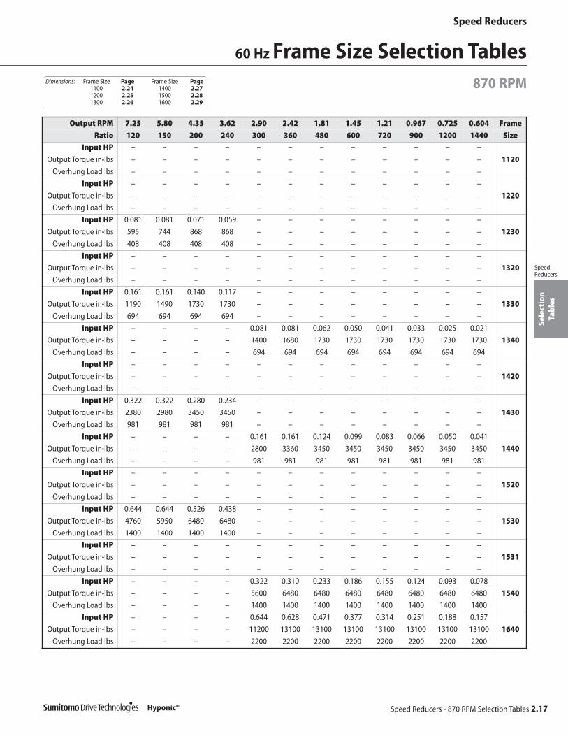
Frame Size Selection Tables 60 Hz
870 RPM
Output RPM 174 124 87.0 72.5 58.0 43.5 34.8 29.0 21.7 17.4 14.5 10.9 8.70 Frame
Ratio 5 7 10 12 15 20 25 30 40 50 60 80 100 Size
Input HP 0.161 0.161 0.161 0.161 0.161 0.161 0.161 0.161 0.081 0.081 0.081 – –
Output Torque in•lbs 49.6 69.5 99.2 119 149 198 248 298 198 248 298 – – 1120
Overhung Load lbs 165 187 209 220 231 254 276 287 298 298 298 – –
Input HP 0.322 0.322 0.322 0.322 0.322 0.322 0.322 0.322 0.161 0.161 0.161 – –
Output Torque in•lbs 99.2 139 198 238 298 397 496 595 397 496 595 – – 1220
Overhung Load lbs 231 254 287 309 331 353 375 386 408 408 408 – –
Input HP – – – – – – – – – – – 0.081 0.081
Output Torque in•lbs – – – – – – – – – – – 397 496 1230
Overhung Load lbs – – – – – – – – – – – 408 408
Input HP 0.644 0.644 0.644 0.644 0.644 0.644 0.644 0.644 0.322 0.322 0.322 – –
Output Torque in•lbs 198 278 397 476 595 794 992 1190 794 992 1190 – – 1320
Overhung Load lbs 386 430 485 507 529 573 617 639 672 694 694 – –
Input HP – – – – – – – – – – – 0.161 0.161
Output Torque in•lbs – – – – – – – – – – – 794 992 1330
Overhung Load lbs – – – – – – – – – – – 694 694
Input HP – – – – – – – – – – – – –
Output Torque in•lbs – – – – – – – – – – – – – 1340
Overhung Load lbs – – – – – – – – – – – – –
Input HP 1.24 1.24 1.24 1.24 1.24 1.24 1.24 1.24 0.644 0.644 0.644 – –
Output Torque in•lbs 382 535 764 917 1150 1530 1910 2290 1590 1980 2380 – – 1420
Overhung Load lbs 584 639 716 750 794 860 904 937 981 981 981 – –
Input HP – – – – – – – – – – – 0.322 0.322
Output Torque in•lbs – – – – – – – – – – – 1590 1980 1430
Overhung Load lbs – – – – – – – – – – – 981 981
Input HP – – – – – – – – – – – – –
Output Torque in•lbs – – – – – – – – – – – – – 1440
Overhung Load lbs – – – – – – – – – – – – –
Input HP 1.77 1.77 1.77 1.77 1.77 1.77 1.77 1.77 1.24 1.24 1.24 – –
Output Torque in•lbs 546 764 1090 1310 1640 2180 2730 3270 3060 3820 4580 – – 1520
Overhung Load lbs 838 915 1040 1080 1150 1230 1300 1360 1400 1400 1400 – –
Input HP – – – – – – – – – – – 0.644 0.644
Output Torque in•lbs – – – – – – – – – – – 3180 3970 1530
Overhung Load lbs – – – – – – – – – – – 1400 1400
Input HP – – – – – – – – 1.77 1.77 1.77 1.24 –
Output Torque in•lbs – – – – – – – – 4370 5460 6550 6110 – 1531
Overhung Load lbs – – – – – – – – 1400 1400 1400 1400 –
Input HP – – – – – – – – – – – – –
Output Torque in•lbs – – – – – – – – – – – – – 1540
Overhung Load lbs – – – – – – – – – – – – –
Input HP – – – – – – – – – – – – –
Output Torque in•lbs – – – – – – – – – – – – – 1640
Overhung Load lbs – – – – – – – – – – – – –
Dimensions: Frame Size Page Frame Size Page1100 2.24 1400 2.271200 2.25 1500 2.281300 2.26 1600 2.29
Speed Reducers
Speed Reducers - 870 RPM Selection Tables 2.17
Sele
ctio
nTa
bles
SpeedReducers
Hyponic®
60 Hz Frame Size Selection Tables870 RPM
Output RPM 7.25 5.80 4.35 3.62 2.90 2.42 1.81 1.45 1.21 0.967 0.725 0.604 Frame
Ratio 120 150 200 240 300 360 480 600 720 900 1200 1440 Size
Input HP – – – – – – – – – – – –
Output Torque in•lbs – – – – – – – – – – – – 1120
Overhung Load lbs – – – – – – – – – – – –
Input HP – – – – – – – – – – – –
Output Torque in•lbs – – – – – – – – – – – – 1220
Overhung Load lbs – – – – – – – – – – – –
Input HP 0.081 0.081 0.071 0.059 – – – – – – – –
Output Torque in•lbs 595 744 868 868 – – – – – – – – 1230
Overhung Load lbs 408 408 408 408 – – – – – – – –
Input HP – – – – – – – – – – – –
Output Torque in•lbs – – – – – – – – – – – – 1320
Overhung Load lbs – – – – – – – – – – – –
Input HP 0.161 0.161 0.140 0.117 – – – – – – – –
Output Torque in•lbs 1190 1490 1730 1730 – – – – – – – – 1330
Overhung Load lbs 694 694 694 694 – – – – – – – –
Input HP – – – – 0.081 0.081 0.062 0.050 0.041 0.033 0.025 0.021
Output Torque in•lbs – – – – 1400 1680 1730 1730 1730 1730 1730 1730 1340
Overhung Load lbs – – – – 694 694 694 694 694 694 694 694
Input HP – – – – – – – – – – – –
Output Torque in•lbs – – – – – – – – – – – – 1420
Overhung Load lbs – – – – – – – – – – – –
Input HP 0.322 0.322 0.280 0.234 – – – – – – – –
Output Torque in•lbs 2380 2980 3450 3450 – – – – – – – – 1430
Overhung Load lbs 981 981 981 981 – – – – – – – –
Input HP – – – – 0.161 0.161 0.124 0.099 0.083 0.066 0.050 0.041
Output Torque in•lbs – – – – 2800 3360 3450 3450 3450 3450 3450 3450 1440
Overhung Load lbs – – – – 981 981 981 981 981 981 981 981
Input HP – – – – – – – – – – – –
Output Torque in•lbs – – – – – – – – – – – – 1520
Overhung Load lbs – – – – – – – – – – – –
Input HP 0.644 0.644 0.526 0.438 – – – – – – – –
Output Torque in•lbs 4760 5950 6480 6480 – – – – – – – – 1530
Overhung Load lbs 1400 1400 1400 1400 – – – – – – – –
Input HP – – – – – – – – – – – –
Output Torque in•lbs – – – – – – – – – – – – 1531
Overhung Load lbs – – – – – – – – – – – –
Input HP – – – – 0.322 0.310 0.233 0.186 0.155 0.124 0.093 0.078
Output Torque in•lbs – – – – 5600 6480 6480 6480 6480 6480 6480 6480 1540
Overhung Load lbs – – – – 1400 1400 1400 1400 1400 1400 1400 1400
Input HP – – – – 0.644 0.628 0.471 0.377 0.314 0.251 0.188 0.157
Output Torque in•lbs – – – – 11200 13100 13100 13100 13100 13100 13100 13100 1640
Overhung Load lbs – – – – 2200 2200 2200 2200 2200 2200 2200 2200
Dimensions: Frame Size Page Frame Size Page1100 2.24 1400 2.271200 2.25 1500 2.281300 2.26 1600 2.29
Speed Reducers
2.18 Speed Reducers - 720 RPM Selection Tables
Sele
ctio
nTa
bles
SpeedReducers
Hyponic®
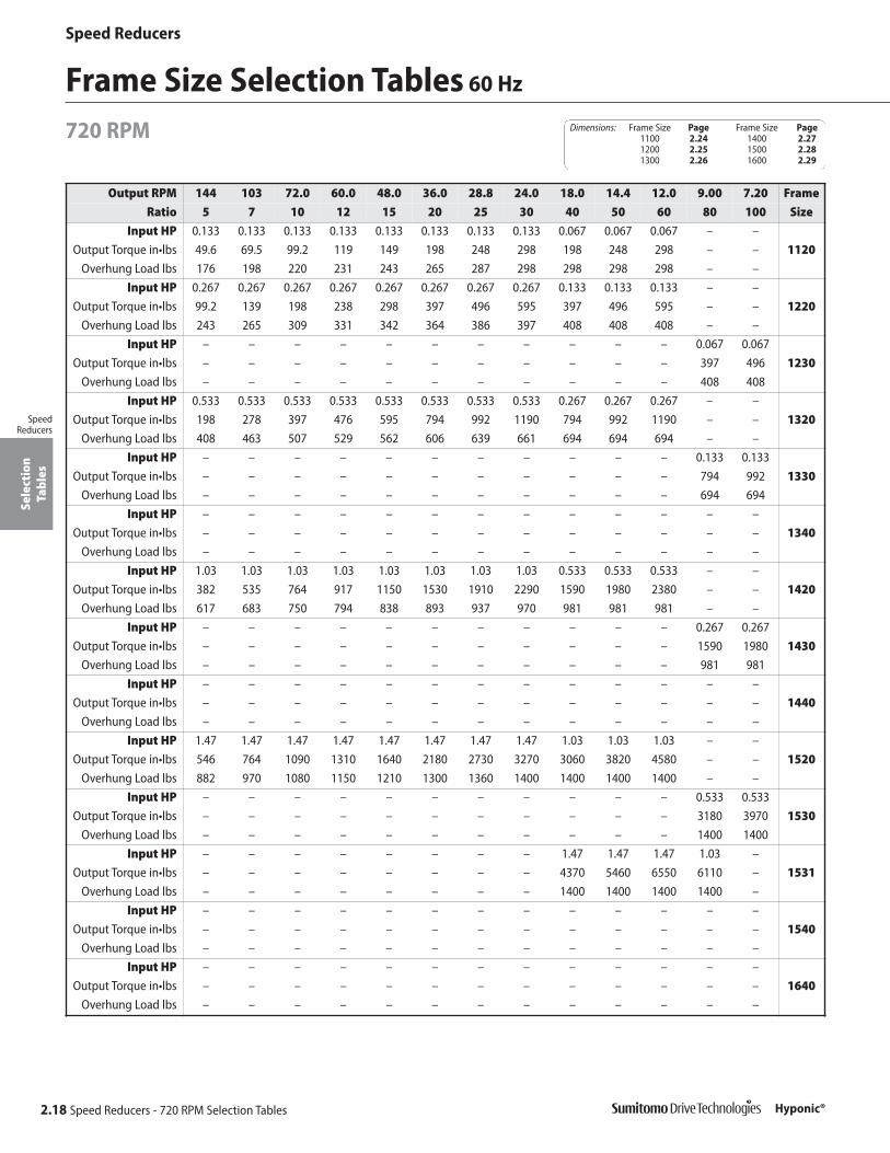
Frame Size Selection Tables 60 Hz
720 RPM
Output RPM 144 103 72.0 60.0 48.0 36.0 28.8 24.0 18.0 14.4 12.0 9.00 7.20 Frame
Ratio 5 7 10 12 15 20 25 30 40 50 60 80 100 Size
Input HP 0.133 0.133 0.133 0.133 0.133 0.133 0.133 0.133 0.067 0.067 0.067 – –
Output Torque in•lbs 49.6 69.5 99.2 119 149 198 248 298 198 248 298 – – 1120
Overhung Load lbs 176 198 220 231 243 265 287 298 298 298 298 – –
Input HP 0.267 0.267 0.267 0.267 0.267 0.267 0.267 0.267 0.133 0.133 0.133 – –
Output Torque in•lbs 99.2 139 198 238 298 397 496 595 397 496 595 – – 1220
Overhung Load lbs 243 265 309 331 342 364 386 397 408 408 408 – –
Input HP – – – – – – – – – – – 0.067 0.067
Output Torque in•lbs – – – – – – – – – – – 397 496 1230
Overhung Load lbs – – – – – – – – – – – 408 408
Input HP 0.533 0.533 0.533 0.533 0.533 0.533 0.533 0.533 0.267 0.267 0.267 – –
Output Torque in•lbs 198 278 397 476 595 794 992 1190 794 992 1190 – – 1320
Overhung Load lbs 408 463 507 529 562 606 639 661 694 694 694 – –
Input HP – – – – – – – – – – – 0.133 0.133
Output Torque in•lbs – – – – – – – – – – – 794 992 1330
Overhung Load lbs – – – – – – – – – – – 694 694
Input HP – – – – – – – – – – – – –
Output Torque in•lbs – – – – – – – – – – – – – 1340
Overhung Load lbs – – – – – – – – – – – – –
Input HP 1.03 1.03 1.03 1.03 1.03 1.03 1.03 1.03 0.533 0.533 0.533 – –
Output Torque in•lbs 382 535 764 917 1150 1530 1910 2290 1590 1980 2380 – – 1420
Overhung Load lbs 617 683 750 794 838 893 937 970 981 981 981 – –
Input HP – – – – – – – – – – – 0.267 0.267
Output Torque in•lbs – – – – – – – – – – – 1590 1980 1430
Overhung Load lbs – – – – – – – – – – – 981 981
Input HP – – – – – – – – – – – – –
Output Torque in•lbs – – – – – – – – – – – – – 1440
Overhung Load lbs – – – – – – – – – – – – –
Input HP 1.47 1.47 1.47 1.47 1.47 1.47 1.47 1.47 1.03 1.03 1.03 – –
Output Torque in•lbs 546 764 1090 1310 1640 2180 2730 3270 3060 3820 4580 – – 1520
Overhung Load lbs 882 970 1080 1150 1210 1300 1360 1400 1400 1400 1400 – –
Input HP – – – – – – – – – – – 0.533 0.533
Output Torque in•lbs – – – – – – – – – – – 3180 3970 1530
Overhung Load lbs – – – – – – – – – – – 1400 1400
Input HP – – – – – – – – 1.47 1.47 1.47 1.03 –
Output Torque in•lbs – – – – – – – – 4370 5460 6550 6110 – 1531
Overhung Load lbs – – – – – – – – 1400 1400 1400 1400 –
Input HP – – – – – – – – – – – – –
Output Torque in•lbs – – – – – – – – – – – – – 1540
Overhung Load lbs – – – – – – – – – – – – –
Input HP – – – – – – – – – – – – –
Output Torque in•lbs – – – – – – – – – – – – – 1640
Overhung Load lbs – – – – – – – – – – – – –
Dimensions: Frame Size Page Frame Size Page1100 2.24 1400 2.271200 2.25 1500 2.281300 2.26 1600 2.29

Speed Reducers
Speed Reducers - 720 RPM Selection Tables 2.19
Sele
ctio
nTa
bles
SpeedReducers
Hyponic®
60 Hz Frame Size Selection Tables720 RPM
Output RPM 6.00 4.80 3.60 3.00 2.40 2.00 1.50 1.20 1.00 0.800 0.600 0.500 Frame
Ratio 120 150 200 240 300 360 480 600 720 900 1200 1440 Size
Input HP – – – – – – – – – – – –
Output Torque in•lbs – – – – – – – – – – – – 1120
Overhung Load lbs – – – – – – – – – – – –
Input HP – – – – – – – – – – – –
Output Torque in•lbs – – – – – – – – – – – – 1220
Overhung Load lbs – – – – – – – – – – – –
Input HP 0.067 0.067 0.058 0.049 – – – – – – – –
Output Torque in•lbs 595 744 868 868 – – – – – – – – 1230
Overhung Load lbs 408 408 408 408 – – – – – – – –
Input HP – – – – – – – – – – – –
Output Torque in•lbs – – – – – – – – – – – – 1320
Overhung Load lbs – – – – – – – – – – – –
Input HP 0.133 0.133 0.116 0.097 – – – – – – – –
Output Torque in•lbs 1190 1490 1730 1730 – – – – – – – – 1330
Overhung Load lbs 694 694 694 694 – – – – – – – –
Input HP – – – – 0.067 0.067 0.051 0.041 0.034 0.027 0.021 0.017
Output Torque in•lbs – – – – 1400 1680 1730 1730 1730 1730 1730 1730 1340
Overhung Load lbs – – – – 694 694 694 694 694 694 694 694
Input HP – – – – – – – – – – – –
Output Torque in•lbs – – – – – – – – – – – – 1420
Overhung Load lbs – – – – – – – – – – – –
Input HP 0.267 0.267 0.232 0.193 – – – – – – – –
Output Torque in•lbs 2380 2980 3450 3450 – – – – – – – – 1430
Overhung Load lbs 981 981 981 981 – – – – – – – –
Input HP – – – – 0.133 0.133 0.103 0.082 0.069 0.055 0.041 0.034
Output Torque in•lbs – – – – 2800 3360 3450 3450 3450 3450 3450 3450 1440
Overhung Load lbs – – – – 981 981 981 981 981 981 981 981
Input HP – – – – – – – – – – – –
Output Torque in•lbs – – – – – – – – – – – – 1520
Overhung Load lbs – – – – – – – – – – – –
Input HP 0.533 0.533 0.435 0.363 – – – – – – – –
Output Torque in•lbs 4760 5950 6480 6480 – – – – – – – – 1530
Overhung Load lbs 1400 1400 1400 1400 – – – – – – – –
Input HP – – – – – – – – – – – –
Output Torque in•lbs – – – – – – – – – – – – 1531
Overhung Load lbs – – – – – – – – – – – –
Input HP – – – – 0.267 0.257 0.193 0.154 0.128 0.103 0.077 0.064
Output Torque in•lbs – – – – 5600 6480 6480 6480 6480 6480 6480 6480 1540
Overhung Load lbs – – – – 1400 1400 1400 1400 1400 1400 1400 1400
Input HP – – – – 0.533 0.520 0.390 0.312 0.260 0.208 0.156 0.130
Output Torque in•lbs – – – – 11200 13100 13100 13100 13100 13100 13100 13100 1640
Overhung Load lbs – – – – 2200 2200 2200 2200 2200 2200 2200 2200
Dimensions: Frame Size Page Frame Size Page1100 2.24 1400 2.271200 2.25 1500 2.281300 2.26 1600 2.29

Speed Reducers
2.20 Speed Reducers - 580 RPM Selection Tables
Sele
ctio
nTa
bles
SpeedReducers
Hyponic®
Frame Size Selection Tables 60 Hz
580 RPM
Output RPM 116 82.9 58.0 48.3 38.7 29.0 23.2 19.3 14.5 11.6 9.67 7.25 5.80 Frame
Ratio 5 7 10 12 15 20 25 30 40 50 60 80 100 Size
Input HP 0.107 0.107 0.107 0.107 0.107 0.107 0.107 0.107 0.054 0.054 0.054 – –
Output Torque in•lbs 49.6 69.5 99.2 119 149 198 248 298 198 248 298 – – 1120
Overhung Load lbs 187 209 231 243 265 287 298 298 298 298 298 – –
Input HP 0.215 0.215 0.215 0.215 0.215 0.215 0.215 0.215 0.107 0.107 0.107 – –
Output Torque in•lbs 99.2 139 198 238 298 397 496 595 397 496 595 – – 1220
Overhung Load lbs 265 287 331 342 364 386 397 408 408 408 408 – –
Input HP – – – – – – – – – – – 0.054 0.054
Output Torque in•lbs – – – – – – – – – – – 397 496 1230
Overhung Load lbs – – – – – – – – – – – 408 408
Input HP 0.430 0.430 0.430 0.430 0.430 0.430 0.430 0.430 0.215 0.215 0.215 – –
Output Torque in•lbs 198 278 397 476 595 794 992 1190 794 992 1190 – – 1320
Overhung Load lbs 441 485 529 562 595 628 661 694 694 694 694 – –
Input HP – – – – – – – – – – – 0.107 0.107
Output Torque in•lbs – – – – – – – – – – – 794 992 1330
Overhung Load lbs – – – – – – – – – – – 694 694
Input HP – – – – – – – – – – – – –
Output Torque in•lbs – – – – – – – – – – – – – 1340
Overhung Load lbs – – – – – – – – – – – – –
Input HP 0.83 0.83 0.83 0.83 0.83 0.83 0.83 0.83 0.430 0.430 0.430 – –
Output Torque in•lbs 382 535 764 917 1150 1530 1910 2290 1590 1980 2380 – – 1420
Overhung Load lbs 661 728 794 838 882 937 970 981 981 981 981 – –
Input HP – – – – – – – – – – – 0.215 0.215
Output Torque in•lbs – – – – – – – – – – – 1590 1980 1430
Overhung Load lbs – – – – – – – – – – – 981 981
Input HP – – – – – – – – – – – – –
Output Torque in•lbs – – – – – – – – – – – – – 1440
Overhung Load lbs – – – – – – – – – – – – –
Input HP 1.18 1.18 1.18 1.18 1.18 1.18 1.18 1.18 0.83 0.83 0.83 – –
Output Torque in•lbs 546 764 1090 1310 1640 2180 2730 3270 3060 3820 4580 – – 1520
Overhung Load lbs 948 1050 1150 1200 1270 1340 1400 1400 1400 1400 1400 – –
Input HP – – – – – – – – – – – 0.430 0.430
Output Torque in•lbs – – – – – – – – – – – 3180 3970 1530
Overhung Load lbs – – – – – – – – – – – 1400 1400
Input HP – – – – – – – – 1.18 1.18 1.18 0.83 –
Output Torque in•lbs – – – – – – – – 4370 5460 6550 6110 – 1531
Overhung Load lbs – – – – – – – – 1400 1400 1400 1400 –
Input HP – – – – – – – – – – – – –
Output Torque in•lbs – – – – – – – – – – – – – 1540
Overhung Load lbs – – – – – – – – – – – – –
Input HP – – – – – – – – – – – – –
Output Torque in•lbs – – – – – – – – – – – – – 1640
Overhung Load lbs – – – – – – – – – – – – –
Dimensions: Frame Size Page Frame Size Page1100 2.24 1400 2.271200 2.25 1500 2.281300 2.26 1600 2.29

Speed Reducers
Speed Reducers - 580 RPM Selection Tables 2.21
Sele
ctio
nTa
bles
SpeedReducers
Hyponic®
60 Hz Frame Size Selection Tables580 RPM
Output RPM 4.83 3.87 2.90 2.42 1.93 1.61 1.21 0.967 0.806 0.644 0.483 0.403 Frame
Ratio 120 150 200 240 300 360 480 600 720 900 1200 1440 Size
Input HP – – – – – – – – – – – –
Output Torque in•lbs – – – – – – – – – – – – 1120
Overhung Load lbs – – – – – – – – – – – –
Input HP – – – – – – – – – – – –
Output Torque in•lbs – – – – – – – – – – – – 1220
Overhung Load lbs – – – – – – – – – – – –
Input HP 0.054 0.054 0.047 0.039 – – – – – – – –
Output Torque in•lbs 595 744 868 868 – – – – – – – – 1230
Overhung Load lbs 408 408 408 408 – – – – – – – –
Input HP – – – – – – – – – – – –
Output Torque in•lbs – – – – – – – – – – – – 1320
Overhung Load lbs – – – – – – – – – – – –
Input HP 0.107 0.107 0.094 0.078 – – – – – – – –
Output Torque in•lbs 1190 1490 1730 1730 – – – – – – – – 1330
Overhung Load lbs 694 694 694 694 – – – – – – – –
Input HP – – – – 0.054 0.054 0.041 0.033 0.028 0.022 0.017 0.014
Output Torque in•lbs – – – – 1400 1680 1730 1730 1730 1730 1730 1730 1340
Overhung Load lbs – – – – 694 694 694 694 694 694 694 694
Input HP – – – – – – – – – – – –
Output Torque in•lbs – – – – – – – – – – – – 1420
Overhung Load lbs – – – – – – – – – – – –
Input HP 0.215 0.215 0.187 0.156 – – – – – – – –
Output Torque in•lbs 2380 2980 3450 3450 – – – – – – – – 1430
Overhung Load lbs 981 981 981 981 – – – – – – – –
Input HP – – – – 0.107 0.107 0.083 0.066 0.055 0.044 0.033 0.028
Output Torque in•lbs – – – – 2800 3360 3450 3450 3450 3450 3450 3450 1440
Overhung Load lbs – – – – 981 981 981 981 981 981 981 981
Input HP – – – – – – – – – – – –
Output Torque in•lbs – – – – – – – – – – – – 1520
Overhung Load lbs – – – – – – – – – – – –
Input HP 0.430 0.430 0.350 0.292 – – – – – – – –
Output Torque in•lbs 4760 5950 6480 6480 – – – – – – – – 1530
Overhung Load lbs 1400 1400 1400 1400 – – – – – – – –
Input HP – – – – – – – – – – – –
Output Torque in•lbs – – – – – – – – – – – – 1531
Overhung Load lbs – – – – – – – – – – – –
Input HP – – – – 0.215 0.207 0.155 0.124 0.103 0.083 0.062 0.052
Output Torque in•lbs – – – – 5600 6480 6480 6480 6480 6480 6480 6480 1540
Overhung Load lbs – – – – 1400 1400 1400 1400 1400 1400 1400 1400
Input HP – – – – 0.430 0.419 0.314 0.251 0.209 0.168 0.126 0.105
Output Torque in•lbs – – – – 11200 13100 13100 13100 13100 13100 13100 13100 1640
Overhung Load lbs – – – – 2200 2200 2200 2200 2200 2200 2200 2200
Dimensions: Frame Size Page Frame Size Page1100 2.24 1400 2.271200 2.25 1500 2.281300 2.26 1600 2.29

Speed Reducers
2.22 Speed Reducers - 50 RPM Selection Tables
Sele
ctio
nTa
bles
SpeedReducers
Hyponic®
Frame Size Selection Tables 60 Hz
50 RPM
Output RPM 10.0 7.14 5.00 4.17 3.33 2.50 2.00 1.67 1.25 1.00 0.833 0.625 0.500 Frame
Ratio 5 7 10 12 15 20 25 30 40 50 60 80 100 Size
Input HP 0.009 0.009 0.009 0.009 0.009 0.009 0.009 0.009 0.005 0.005 0.005 – –
Output Torque in•lbs 49.6 69.5 99.2 119 149 198 248 298 198 248 298 – – 1120
Overhung Load lbs 298 298 298 298 298 298 298 298 298 298 298 – –
Input HP 0.019 0.019 0.019 0.019 0.019 0.019 0.019 0.019 0.009 0.009 0.009 – –
Output Torque in•lbs 99.2 139 198 238 298 397 496 595 397 496 595 – – 1220
Overhung Load lbs 408 408 408 408 408 408 408 408 408 408 408 – –
Input HP – – – – – – – – – – – 0.005 0.005
Output Torque in•lbs – – – – – – – – – – – 397 496 1230
Overhung Load lbs – – – – – – – – – – – 408 408
Input HP 0.037 0.037 0.037 0.037 0.037 0.037 0.037 0.037 0.019 0.019 0.019 – –
Output Torque in•lbs 198 278 397 476 595 794 992 1190 794 992 1190 – – 1320
Overhung Load lbs 694 694 694 694 694 694 694 694 694 694 694 – –
Input HP – – – – – – – – – – – 0.009 0.009
Output Torque in•lbs – – – – – – – – – – – 794 992 1330
Overhung Load lbs – – – – – – – – – – – 694 694
Input HP – – – – – – – – – – – – –
Output Torque in•lbs – – – – – – – – – – – – – 1340
Overhung Load lbs – – – – – – – – – – – – –
Input HP 0.07 0.07 0.07 0.07 0.07 0.07 0.07 0.07 0.037 0.037 0.037 – –
Output Torque in•lbs 382 535 764 917 1150 1530 1910 2290 1590 1980 2380 – – 1420
Overhung Load lbs 981 981 981 981 981 981 981 981 981 981 981 – –
Input HP – – – – – – – – – – – 0.019 0.019
Output Torque in•lbs – – – – – – – – – – – 1590 1980 1430
Overhung Load lbs – – – – – – – – – – – 981 981
Input HP – – – – – – – – – – – – –
Output Torque in•lbs – – – – – – – – – – – – – 1440
Overhung Load lbs – – – – – – – – – – – – –
Input HP 0.10 0.10 0.10 0.10 0.10 0.10 0.10 0.10 0.07 0.07 0.07 – –
Output Torque in•lbs 546 764 1090 1310 1640 2180 2730 3270 3060 3820 4580 – – 1520
Overhung Load lbs 1400 1400 1400 1400 1400 1400 1400 1400 1400 1400 1400 – –
Input HP – – – – – – – – – – – 0.037 0.037
Output Torque in•lbs – – – – – – – – – – – 3180 3970 1530
Overhung Load lbs – – – – – – – – – – – 1400 1400
Input HP – – – – – – – – 0.10 0.10 0.10 0.07
Output Torque in•lbs – – – – – – – – 4370 5460 6550 6110 1531
Overhung Load lbs – – – – – – – – 1400 1400 1400 1400
Input HP – – – – – – – – – – – – –
Output Torque in•lbs – – – – – – – – – – – – – 1540
Overhung Load lbs – – – – – – – – – – – – –
Input HP – – – – – – – – – – – – –
Output Torque in•lbs – – – – – – – – – – – – – 1640
Overhung Load lbs – – – – – – – – – – – – –
Dimensions: Frame Size Page Frame Size Page1100 2.24 1400 2.271200 2.25 1500 2.281300 2.26 1600 2.29

Speed Reducers
Speed Reducers - 50 RPM Selection Tables 2.23
Sele
ctio
nTa
bles
SpeedReducers
Hyponic®
60 Hz Frame Size Selection Tables50 RPM
Output RPM 0.417 0.333 0.250 0.208 0.167 0.139 0.104 0.083 0.069 0.056 0.042 0.035 Frame
Ratio 120 150 200 240 300 360 480 600 720 900 1200 1440 Size
Input HP – – – – – – – – – – – –
Output Torque in•lbs – – – – – – – – – – – – 1120
Overhung Load lbs – – – – – – – – – – – –
Input HP – – – – – – – – – – – –
Output Torque in•lbs – – – – – – – – – – – – 1220
Overhung Load lbs – – – – – – – – – – – –
Input HP 0.005 0.005 0.004 0.003 – – – – – – – –
Output Torque in•lbs 595 744 868 868 – – – – – – – – 1230
Overhung Load lbs 408 408 408 408 – – – – – – – –
Input HP – – – – – – – – – – – –
Output Torque in•lbs – – – – – – – – – – – – 1320
Overhung Load lbs – – – – – – – – – – – –
Input HP 0.009 0.009 0.008 0.007 – – – – – – – –
Output Torque in•lbs 1190 1490 1730 1730 – – – – – – – – 1330
Overhung Load lbs 694 694 694 694 – – – – – – – –
Input HP – – – – 0.005 0.005 0.004 0.003 0.002 0.002 0.001 0.001
Output Torque in•lbs – – – – 1400 1680 1730 1730 1730 1730 1730 1730 1340
Overhung Load lbs – – – – 694 694 694 694 694 694 694 694
Input HP – – – – – – – – – – – –
Output Torque in•lbs – – – – – – – – – – – – 1420
Overhung Load lbs – – – – – – – – – – – –
Input HP 0.019 0.019 0.016 0.013 – – – – – – – –
Output Torque in•lbs 2380 2980 3450 3450 – – – – – – – – 1430
Overhung Load lbs 981 981 981 981 – – – – – – – –
Input HP – – – – 0.009 0.009 0.007 0.006 0.005 0.004 0.003 0.002
Output Torque in•lbs – – – – 2800 3360 3450 3450 3450 3450 3450 3450 1440
Overhung Load lbs – – – – 981 981 981 981 981 981 981 981
Input HP – – – – – – – – – – – –
Output Torque in•lbs – – – – – – – – – – – – 1520
Overhung Load lbs – – – – – – – – – – – –
Input HP 0.037 0.037 0.030 0.025 – – – – – – – –
Output Torque in•lbs 4760 5950 6480 6480 – – – – – – – – 1530
Overhung Load lbs 1400 1400 1400 1400 – – – – – – – –
Input HP – – – – – – – – – – – –
Output Torque in•lbs – – – – – – – – – – – – 1531
Overhung Load lbs – – – – – – – – – – – –
Input HP – – – – 0.019 0.018 0.013 0.011 0.009 0.007 0.005 0.004
Output Torque in•lbs – – – – 5600 6480 6480 6480 6480 6480 6480 6480 1540
Overhung Load lbs – – – – 1400 1400 1400 1400 1400 1400 1400 1400
Input HP – – – – 0.037 0.036 0.027 0.022 0.018 0.014 0.011 0.009
Output Torque in•lbs – – – – 11200 13100 13100 13100 13100 13100 13100 13100 1640
Overhung Load lbs – – – – 2200 2200 2200 2200 2200 2200 2200 2200
Dimensions: Frame Size Page Frame Size Page1100 2.24 1400 2.271200 2.25 1500 2.281300 2.26 1600 2.29

Speed Reducers
2.24 Speed ReducersDimensions
Dim
ensi
ons
SpeedReducers
Hyponic®
DimensionsFrame Size 1100RNYJ-1120Y
Dimensions shown are for reference only and are subject to change without notice, unless certified.Certified prints are available after receipt of an order; consult factory.
All dimensions are in inches.
Ø.78
3.23
.591
Ø.796
1.22
.039
1.22Ø.750
.1875
+.0013+.0005
Model A B min B max D E F G H J K L N P R X
1120Y 3.54 2.046 2.047 1.30 1.65 0.31 2.60 0.26 1.97 1.26 1.57 3.23 0.24 0.79 0.87
Model RatioNEMAFrame
CE C XJ AK BD AJ BF Z BBMin.
IDZA
Wt. (lbs.)
RNYJ-1120Y 5~60 42C 10.72 8.94 1.78 3.0 4.33 3.75 0.28 0.47 – 2.44 – 12
RNYJ-1120Y 5~60 48C 11.11 8.94 2.16 3.0 4.33 3.75 0.28 0.47 – 2.44 – 13
RNYJ-1120Y 5~30 56C 11.47 8.94 2.56 4.5 6.69 5.87 0.43 0.47 – 3.15 – 15

Speed Reducers
Speed Reducers 2.25Dimensions
Dim
ensi
ons
SpeedReducers
Hyponic® Dimensions shown are for reference only and are subject to change without notice, unless certified.Certified prints are available after receipt of an order; consult factory.
DimensionsFrame Size 1200
RNYJ-1220/30Y
All dimensions are in inches.
Ø1.01
3.62
.827
Ø1.066
1.50
.046
1.50Ø1.00
.25
+.0013+.0005
Model A B min B max D E F G H J K L N P R X
1220Y 4.53 3.070 3.071 1.46 2.24 0.35 2.91 0.35 2.60 1.57 1.93 3.78 0.20 1.10 0.79
1230Y 5.00 3.070 3.071 1.61 2.56 0.35 3.23 0.35 2.99 1.57 2.01 3.74 0.20 0.51 0.31
Model RatioNEMAFrame
CE C XJ AK BD AJ BF Z BBMin.
IDZA
Wt. (lbs.)
RNYJ-1220Y 5~60 48C 12.40 10.24 2.16 3.0 4.33 3.75 0.28 0.47 – 2.44 – 16
RNYJ-1220Y 5~60 56C 12.80 10.24 2.56 4.5 6.69 5.87 0.43 0.47 – 3.15 – 17
RNYJ-1230Y 80~240 42C 11.66 9.88 1.78 3.0 4.33 3.75 0.28 0.47 – 2.44 – 16
RNYJ-1230Y 80~240 48C 12.04 9.88 2.16 3.0 4.33 3.75 0.28 0.47 – 2.44 – 16
RNYJ-1230Y 80~240 56C 12.42 9.88 2.56 4.5 6.69 5.87 0.43 0.47 – 3.15 – 18

Speed ReducersD
imen
sion
s
SpeedReducers
DimensionsFrame Size 1300RNYJ-1320/30/40Y
Dimensions shown are for reference only and are subject to change without notice, unless certified.Certified prints are available after receipt of an order; consult factory.
Hyponic®
All dimensions are in inches.
Ø1.28
4.33
.827
Ø1.33
1.81
.056
1.81Ø1.25
.25
+.0015+.0006
Model A B min B max D E F G H J K L N P R X
1320Y 5.20 3.345 3.346 1.81 2.44 0.35 3.62 0.43 2.91 1.81 2.28 4.69 0.20 1.08 1.34
1330Y 5.98 3.345 3.346 1.81 3.11 0.35 3.62 0.43 3.62 1.85 2.36 4.25 0.20 0.43 0.14
1340Y 5.98 3.345 3.346 1.81 3.11 0.35 3.62 0.43 3.62 1.85 2.36 5.16 0.20 0.35 1.04
Model RatioNEMAFrame
CE C XJ AK BD AJ BF Z BBMin.
IDZA
Wt. (lbs.)
RNYJ-1320Y 5~60 56C 14.52 11.89 2.63 4.5 6.69 5.87 0.43 0.47 – 4.21 4.53 29
RNYJ-1320Y 5~30 143TC 14.52 11.89 2.63 4.5 6.69 5.87 0.43 0.47 – 4.21 4.53 29
RNYJ-1330Y 80~240 48C 13.30 11.14 2.16 3.0 4.33 3.75 0.28 0.47 – 2.44 – 20
RNYJ-1330Y 80~240 56C 13.68 11.14 2.56 4.5 6.69 5.87 0.43 0.47 – 3.15 – 22
RNYJ-1340Y 300~1440 42C 13.45 11.66 1.78 3.0 4.33 3.75 0.28 0.47 – 2.44 – 22
RNYJ-1340Y 300~720 48C 13.81 11.66 2.16 3.0 4.33 3.75 0.28 0.47 – 2.44 – 22
RNYJ-1340Y 300~720 56C 14.21 11.66 2.56 4.5 6.69 5.87 0.43 0.47 – 3.15 – 24
2.26 Speed ReducersDimensions

Speed Reducers
Dim
ensi
ons
SpeedReducers
DimensionsFrame Size 1400
RNYJ-1420/30/40Y
Dimensions shown are for reference only and are subject to change without notice, unless certified.Certified prints are available after receipt of an order; consult factory.
Hyponic®
All dimensions are in inches.
Ø1.40
5.43
1.02
Ø1.46
2.05
.056
2.05Ø1.375
.3125
+.0015+.0006
Model A B min B max D E F G H J K L N P R X
1420Y 6.22 3.739 3.740 2.32 2.95 0.39 4.65 0.55 3.46 2.24 2.76 5.75 0.20 0.79 1.69
1430Y 7.01 3.739 3.740 2.32 3.62 0.39 4.65 0.55 4.25 2.13 2.76 5.12 0.20 0.55 0.31
1440Y 7.01 3.739 3.740 2.32 3.62 0.39 4.65 0.55 4.25 2.13 2.76 6.42 0.20 0.43 1.73
Model RatioNEMAFrame
CE C XJ AK BD AJ BF Z BBMin.
IDZA
Wt.(lbs.)
RNYJ-1420Y 40~60 143TC 15.93 13.31 2.63 4.5 6.69 5.87 0.43 0.47 – 4.21 4.53 36
RNYJ-1420Y 5~30 145TC 16.29 13.66 2.63 4.5 6.69 5.87 0.43 0.47 – 4.21 4.53 36
RNYJ-1430Y 80~120 56C 15.42 12.80 2.63 4.5 6.69 5.87 0.43 0.47 – 4.21 4.53 38
RNYJ-1430Y 150~240 56C 15.46 12.83 2.63 4.5 6.69 5.87 0.43 0.47 – 4.21 4.53 38
RNYJ-1440Y 300~1440 48C 15.86 13.70 2.16 3.0 4.33 3.75 0.28 0.47 – 2.44 – 32
RNYJ-1440Y 300~720 56C 16.26 13.70 2.56 4.5 6.69 5.87 0.43 0.47 – 4.21 – 32
Speed Reducers 2.27Dimensions
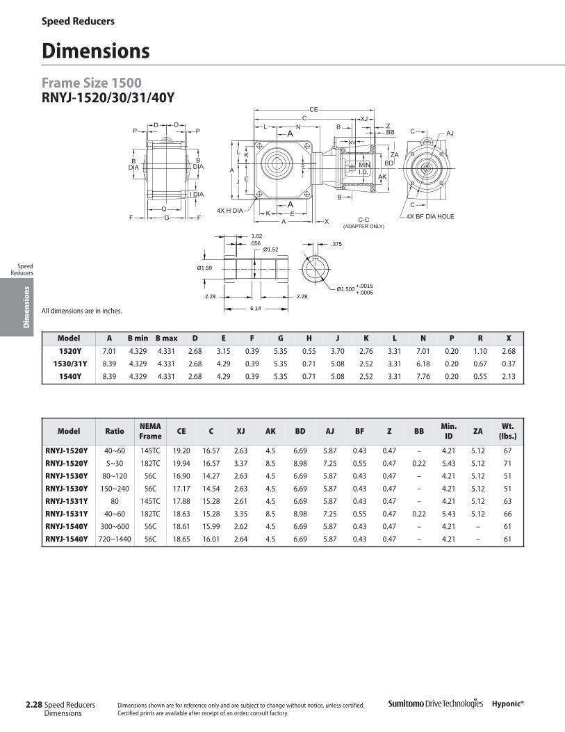
Speed ReducersD
imen
sion
s
SpeedReducers
Hyponic®
DimensionsFrame Size 1500RNYJ-1520/30/31/40Y
Dimensions shown are for reference only and are subject to change without notice, unless certified.Certified prints are available after receipt of an order; consult factory.
All dimensions are in inches.
Ø1.52
6.14
1.02
Ø1.59
2.28
.056
2.28Ø1.500
.375
+.0015+.0006
Model A B min B max D E F G H J K L N P R X
1520Y 7.01 4.329 4.331 2.68 3.15 0.39 5.35 0.55 3.70 2.76 3.31 7.01 0.20 1.10 2.68
1530/31Y 8.39 4.329 4.331 2.68 4.29 0.39 5.35 0.71 5.08 2.52 3.31 6.18 0.20 0.67 0.37
1540Y 8.39 4.329 4.331 2.68 4.29 0.39 5.35 0.71 5.08 2.52 3.31 7.76 0.20 0.55 2.13
Model RatioNEMAFrame
CE C XJ AK BD AJ BF Z BBMin.
IDZA
Wt. (lbs.)
RNYJ-1520Y 40~60 145TC 19.20 16.57 2.63 4.5 6.69 5.87 0.43 0.47 – 4.21 5.12 67
RNYJ-1520Y 5~30 182TC 19.94 16.57 3.37 8.5 8.98 7.25 0.55 0.47 0.22 5.43 5.12 71
RNYJ-1530Y 80~120 56C 16.90 14.27 2.63 4.5 6.69 5.87 0.43 0.47 – 4.21 5.12 51
RNYJ-1530Y 150~240 56C 17.17 14.54 2.63 4.5 6.69 5.87 0.43 0.47 – 4.21 5.12 51
RNYJ-1531Y 80 145TC 17.88 15.28 2.61 4.5 6.69 5.87 0.43 0.47 – 4.21 5.12 63
RNYJ-1531Y 40~60 182TC 18.63 15.28 3.35 8.5 8.98 7.25 0.55 0.47 0.22 5.43 5.12 66
RNYJ-1540Y 300~600 56C 18.61 15.99 2.62 4.5 6.69 5.87 0.43 0.47 – 4.21 – 61
RNYJ-1540Y 720~1440 56C 18.65 16.01 2.64 4.5 6.69 5.87 0.43 0.47 – 4.21 – 61
2.28 Speed ReducersDimensions

Speed Reducers
Dim
ensi
ons
SpeedReducers
Hyponic®
DimensionsFrame Size 1600
RNYJ-1640Y
Dimensions shown are for reference only and are subject to change without notice, unless certified.Certified prints are available after receipt of an order; consult factory.
A
EFGF
P
B DIA
P
D D
K
A
L
EJ
K
R
JL
4X H DIA
B DIA
ZA
AJ
N
XV
BD
Z
AKMINI.D.
ZA
4X DIA BF HOLE
C-C(ADAPTER ONLY)
LC XJ
CE
A
AB
BC
C
1
2
All dimensions are in inches.
Ø2.02
8.82
1.18
Ø2.12
2.99
.068
2.99Ø2.00
.500
+.0018+.0006
Model A B min B max D E F G H J K L N P R ZA1
1640Y 11.02 5.904 5.906 3.66 5.71 0.75 7.32 0.87 6.69 3.35 4.33 9.29 0.47 0.67 6.30
Model RatioNEMA Frame
CE C XJ AK BD AJ BF ZMin.
IDZA2 WT.
RNYJ-1640Y 300~720 56C ~ 143TC 21.09 18.46 2.63 4.5 6.69 5.87 0.43 0.47 4.21 6.97 146
RNYJ-1640Y 900~1440 56C ~ 143TC 21.36 18.74 2.62 4.5 6.69 5.87 0.43 0.47 4.21 6.97 146
Speed Reducers 2.29Dimensions

This page intentionally left blank.
Speed Reducers
2.30 Speed Reducers Hyponic®
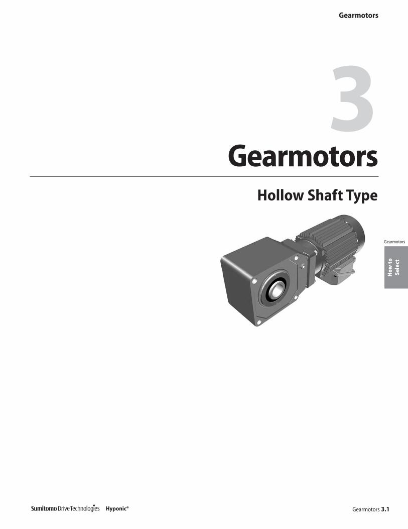
How
toSe
lect
Gearmotors
Gearmotors 3.1Hyponic®
Gearmotors3
Gearmotors
Hollow Shaft Type

Prod
uct
Ran
geGearmotors
3.2 Gearmotors
Gearmotors
Hyponic®
Product RangeHollow Shaft Type
5 7 10 12 15 20 25 30 40 50 60350 250 175 145.83 116.67 87.5 70 58.33 43.75 35 29.17
1/3HP
3/4HP
1.5HP
7.5HP
1/2HP
1/3HP
1/2HP
3/4HP
1HP
1.5HP
2HP
3HP
5HP
Nominal Ratio (:1)Output RPM (1750 rpm input)
Size 1220, Bore Ø1.00"
Size 1220, Bore Ø1.00"Size 1120, Bore Ø0.75"
Size 1220, Bore Ø1.00" Size 1320, Bore Ø1.25"
Size 1420, Bore Ø1.375"
Size 1320, Bore Ø1.25"Size 1220, Bore Ø1.00"
Size 1220, Bore Ø1.00" Size 1320, Bore Ø1.25"
1/8HP
1/4HP
1/2HP
Size 1320, Bore Ø1.25"
Size 1320, Bore Ø1.25"
Size 1120, Bore Ø0.75"
Size 1420, Bore Ø1.375"
Size 1420, Bore Ø1.375"
Size 1420, Bore Ø1.375" Size 1520, Bore Ø1.50"
Size 1320, Bore Ø1.25"
2HP
3HPSize 1520, Bore Ø1.50" Size 1531, Bore Ø1.50"
Size 1521, Bore Ø1.50" Size 1632, Bore Ø2.00"
Size 1520, Bore Ø1.50" Size 1531, Bore Ø1.50"
3-Phase
Size 1521, Bore Ø1.50" Size 1632, Bore Ø2.00"
Size 1522, Bore Ø1.50" Size 1633, Bore Ø2.00"
1HP
Size 1420, Bore Ø1.375" Size 1520, Bore Ø1.50"
Size 1420, Bore Ø1.375" Size 1520, Bore Ø1.50"
Size 1120, Bore Ø0.75"
5HP
Size 1522, Bore Ø1.50" Size 1633, Bore Ø2.00"
1/8HP
Size 1120, Bore Ø0.75" Size 1220, Bore Ø1.00"
Size 1220, Bore Ø1.00"
Size 1220, Bore Ø1.00" Size 1320, Bore Ø1.25"
Size 1320, Bore Ø1.25" Size 1420, Bore Ø1.375"
1/4HPSinglePhase
1/8HP
InverterDuty10:1
ConstantTorqueSpeedRange
1/4HP
Size 1120, Bore Ø0.75"Size 1220, Bore Ø1.00"
Size 1120, Bore Ø0.75" Size 1220, Bore Ø1.00"
Size 1220, Bore Ø1.00" Size 1320, Bore Ø1.25"
Size 1420, Bore Ø1.375"
Size 1220, Bore Ø1.00" Size 1320, Bore Ø1.25"
Size 1320, Bore Ø1.25"
Size 1420, Bore Ø1.375" Size 1520, Bore Ø1.50"
Size 1420, Bore Ø1.375" Size 1520, Bore Ø1.50"
Size 1520, Bore Ø1.50" Size 1531, Bore Ø1.50"
Size 1522, Bore Ø1.50" Size 1633, Bore Ø2.00"
Size 1520, Bore Ø1.50" Size 1531, Bore Ø1.50"
Size 1521, Bore Ø1.50" Size 1632, Bore Ø2.00"
Selections shaded in blue offer an increased service factor. Please refer to the gearmotor selection tables for specific unit service factor details.
Note: [1] This frame size is torque limited. Overload may occur if the motor is loaded to its full capacity. Sumitomo recommends the use of a torque limiting deviceto protect the unit and/or the driven machine.

Prod
uct
Ran
ge
Gearmotors
Gearmotors 3.3
Gearmotors
Hyponic®
80 100 120 150 200 240 300 360 480 600 720 900 1200 144021.88 17.5 14.58 11.67 8.75 7.29 5.83 4.86 3.65 2.92 2.43 1.94 1.46 1.22
Size 1531Bore Ø1.50"
Size 1531Bore Ø1.50"
Size 1531Bore Ø1.50"
Size 1531Bore Ø1.50"
Size 1531Bore Ø1.50"
Size 1631, Bore Ø2.00"
Size 1540, Bore Ø1.50"
Size 1340, Bore Ø1.25" Size 1440, Bore Ø1.375" [1]
Size 1440, Bore Ø1.375" Size 1540, Bore Ø1.50"
Size 1440, Bore Ø1.375" Size 1540, Bore Ø1.50" [1]
Size 1540, Bore Ø1.50" Size 1640, Bore Ø2.00"
Size 1440, Bore Ø1.375" [1]
Size 1230, Bore Ø1.00" [1]
Size 1330, Bore Ø1.25"
Size 1330, Bore Ø1.25" [1]
Size 1540, Bore Ø1.50" [1]
Size 1430, Bore Ø1.375"
Size 1340, Bore Ø1.25" [1]
Size 1440, Bore Ø1.375" [1]
Size 1540, Bore Ø1.50" [1]
Size 1430, Bore Ø1.375"
Size 1640, Bore Ø2.00" [1]
Size 1430, Bore Ø1.375" [1] Size 1540, Bore Ø1.50" [1]
Size 1530, Bore Ø1.375"
Size 1530, Bore Ø1.375" Size 1640, Bore Ø2.00" [1]
Size 1630, Bore Ø2.00"
Size 1530, Bore Ø1.375"
Size 1640, Bore Ø2.00" [1]
Size 1631, Bore Ø2.00"
Size 1630, Bore Ø2.00"Size 1631, Bore Ø2.00" [1]
Size 1631, Bore Ø2.00"Size 1630, Bore Ø2.00"
Size 1631, Bore Ø2.00" [1]Size 1630, Bore Ø2.00"
Size 1230, Bore Ø1.00" [1] Size 1340, Bore Ø1.25" Size 1440, Bore Ø1.375" [1]
Size 1440, Bore Ø1.375"
Size 1330, Bore Ø1.25" [1] Size 1440, Bore Ø1.375" Size 1540, Bore Ø1.50" [1]
Size 1330, Bore Ø1.25"
Size 1430, Bore Ø1.375" Size 1640, Bore Ø2.00"Size 1540, Bore Ø1.50"
Size 1530, Bore Ø1.50" Size 1640, Bore Ø2.00" [1]
Size 1230, Bore Ø1.00" [1]
Size 1330, Bore Ø1.25"
Size 1640, Bore Ø2.00" [1]
Size 1330, Bore Ø1.25" [1]
Size 1430, Bore Ø1.375"
Size 1640, Bore Ø2.00" [1]
Size 1631, Bore Ø2.00"Size 1630, Bore Ø2.00"
Size 1530, Bore Ø1.50"
Size 1430, Bore Ø1.375" Size 1540, Bore Ø1.50"
Size 1630, Bore Ø2.00" Size 1631, Bore Ø2.00"
Size 1631, Bore Ø2.00"Size 1630, Bore Ø2.00"
Size 1630, Bore Ø2.00"

How
toSe
lect
Gearmotors
3.4 Gearmotors Hyponic®
Gearmotors
How to Select a Gearmotor
Step 1: Collect data about your applicationBefore starting you need to know the:
• Application (e.g. Conveyor, Mixer, etc.)• Hours of Operation per day• Motor Horsepower (HP) and Speed (RPM)• Desired Output Speed• Mounting Position and Style• Overhung or Thrust Loads• Bore Dimensions, inch or metric• Electrical Specifications
Step 2: Select a Frame Size2A: Find the Load Classification of your application in theAGMA Load Classification Tables on pages 3.8 and 3.9.
2B: Go to the Gearmotor Selection Table that corresponds tothe desired Motor HP. Find the Output Speed closest to thedesired output speed.
2C: Locate the Service Class in the Gearmotor Selection Tablefor your application and select the Frame Size SELECTIONthat matches the HP, Output Speed, and Service Class.
Step 3: Verify DimensionsUse the Dimensions information on pages 3.30–3.40 toverify that the selected Frame Size is appropriate.
Step 4: Choose OptionsThe following options may apply:Solid ShaftMounting FeetOutput FlangeTorque Arm AssemblyWashdown AssemblyPlease see the Hyponic® pricelist for available modifications, andrefer to Section 4 of this catalog for dimension drawings of selected popular options .
Step 5: Configure a Model NumberGo to page 3.6 to configure a model number.Note: You will use the information you gather from the procedure on this page to Configure a Model Number.
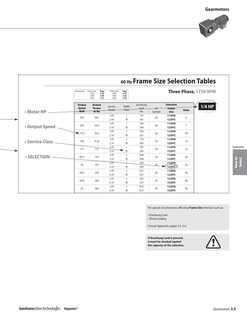
How
toSe
lect
If Overhung Load is present,it must be checked againstthe capacity of the selection.
G
60 Hz Frame Size Selection TablesThree-Phase, 1750 RPM
1/4 HPOutputSpeed RPM
OutputTorque in-lbs
Service Factor
AGMAClass
OverhungLoad lbs
SelectionHP
SymbolFrame
SizeRatio
350 38.31.07 I 132
021120YA
52.14 III 187 1220YC
250 53.61.07 I 143
021120YA
72.14 III 209 1220YC
175 76.51.07 I 165
021120YA
102.14 III 231 1220YC
146 91.81.07 I 176
021120YA
122.14 III 243 1220YC
117 1151.07 I 187
021120YA
152.14 III 265 1220YC
87.5 1531.07 I 209
021120YA
202.14 III 298 1220YC
70 1911.07 I 220
021120YA
252.14 III 309 1220YC
58.3 2301.07 I 231
021120YA
302.14 III 331 1220YC
43.8 3061.07 I 353
021220YA
402.14 III 573 1320YC
35 3831.07 I 375
021220YA
502.14 III 617 1320YC
Dimensions: Frame Size Page Frame Size Page1100 3.28 1400 3.341200 3.30 1500 3.361300 3.32 1600 3.38
Gearmotors
Gearmotors
Gearmotors 3.5Hyponic®
For special circumstances affecting Frame Size selection such as:
• Overhung Load• Shock Loading
Consult Appendix, pages 5.5–5.6.
• Service Class
• SELECTION
• Motor HP
• Output Speed

Nom
encl
atur
e Gearmotors
3.6 Gearmotors
Gearmotors
Hyponic®
Configure a Model Number
AGMAclass
Brake
Gearmotor Specification
Class SuffixI AII BIII C
SuffixWith Brake BNo Brake –
AGMA Class
Brake
R N Y M 20J1AY1 2 2 005
Hyponic product code (always “R”)
Output shaft orientation
Mounting style
Input connection
Modification (Special feature)
Gearmotor HP(1750 rpm)
Frame size
Optional Specification (as required)
Ratio
Shaft specification
Output Shaft Orientation
HP Prefix1/8 011/4 021/3 031/2 053/4 08
1 11 1/2 1H
2 23 35 5
7 1/2 8
Mounting Style
Input Connection
Modification
Gearmotor HP(applies only to
1750 RPM)
Include the following information when ordering:
• Motor Specification (230/460 VAC 60 Hz is supplied, unless otherwise specified
• NEMA frame size for C-face adaptor
• Optional conduit box positions must be specified, otherwise the standard positionis supplied.
- --
Gearmotor Specification
Input Connection Prefix
Integral Motor M
Type Prefix
Universal Direction(Maintenance Free)
N
Type Prefix
Shaft Mount (Hollow Shaft) Y
Flange (Solid Shaft) F
Foot (Solid Shaft) H
Prefix
Special S
Standard
Output shaft direction (shafted model only)
L -
Output Shaft Direction (shafted model only)
Direction (when viewed from motor end) Suffix
Projects to Left Side L
Projects to Right Side R
Projects to Both Sides T
Specification Suffix
Three-Phase Motor
Single-Phase Motor CB
AF Motor (Adjustable Frequency AV
Frame Size
1120 15211220 15221230 15301320 15311330 15401340 16301420 16311430 16321440 16331520 1640

Nom
encl
atur
e
Gearmotors
Gearmotors 3.7
Gearmotors
Hyponic®
Nomenclature Example:
RNHM05 – 1220L YA –J1 – 20R – Hyponic® 1220 – Frame SizeN – Universal Mount L – L O/P Shaft DirectionH – Foot (Solid Shaft) Y – Inch Shaft SpecificationM – Integral Motor A – AGMA Class I05 – 1/2 HP, 1750 RPM J1 – Bolt-on Feet, Bottom
20 – Ratio
Nomenclature
Optional Specifications (as required)
Nominal Total Ratio
Shaft Specifications
Input Shaft
Output ShaftSuffix
Hollow Solid
mm Key (mm) Key (mm)
Inch Key (Inch) Key (Inch) Y
5 20 60 200 600
7 25 80 240 720
10 30 100 300 900
12 40 120 360 1200
15 50 150 480 1440
Specification Suffix
Hollow Bore Options
Extended Flange (for motor clearance)
Left (viewed from motor end) F1
Right (viewed from motor end) G1
Solid Shaft Options
Plug-in Shaft X1
Plug-in Shaft with Bolt-on Feet
Bottom J1
Opposite from Motor S1
Top M1
Plug-in Shaft with Extended Flange(for motor clearance)
Left (viewed from motor end) P1
Right (viewed from motor end) Q1
F1 G1
J1
X1
S1 M1
P1 Q1
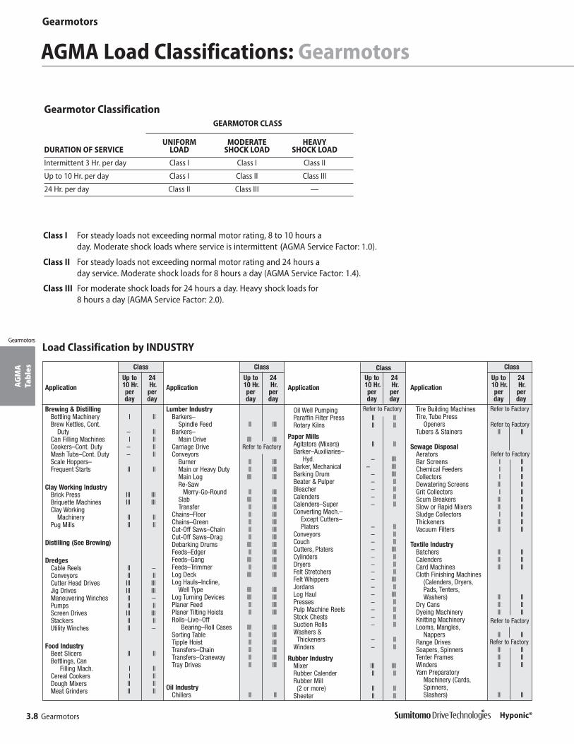
AG
MA
Ta
bles
Gearmotors
3.8 Gearmotors
Gearmotors
Hyponic®
AGMA Load Classifications: Gearmotors
Class I For steady loads not exceeding normal motor rating, 8 to 10 hours a day. Moderate shock loads where service is intermittent (AGMA Service Factor: 1.0).
Class II For steady loads not exceeding normal motor rating and 24 hours a day service. Moderate shock loads for 8 hours a day (AGMA Service Factor: 1.4).
Class III For moderate shock loads for 24 hours a day. Heavy shock loads for 8 hours a day (AGMA Service Factor: 2.0).
Up to10 Hr.perday
24Hr.
perday
Up to10 Hr.perday
24Hr.
perday
Up to10 Hr.perday
24Hr.
perday
Up to10 Hr.perday
24Hr.
perday
Refer to Factory
Load Classification by INDUSTRY
Refer to Factory
Refer to Factory
Refer to Factory
Refer to Factory
Refer to Factory
Refer to Factory
Gearmotor ClassificationGEARMOTOR CLASS
UNIFORM MODERATE HEAVYDURATION OF SERVICE LOAD SHOCK LOAD SHOCK LOAD
Intermittent 3 Hr. per day Class I Class I Class II
Up to 10 Hr. per day Class I Class II Class III
24 Hr. per day Class II Class III —
Class
Application
Brewing & DistillingBottling Machinery I IIBrew Kettles, Cont.
Duty – IICan Filling Machines I IICookers–Cont. Duty – IIMash Tubs–Cont. Duty – IIScale Hoppers–Frequent Starts II II
Clay Working IndustryBrick Press III IIIBriquette Machines III IIIClay Working
Machinery II IIPug Mills II II
Distilling (See Brewing)
DredgesCable Reels II –Conveyors II IICutter Head Drives III IIIJig Drives III IIIManeuvering Winches II –Pumps II IIScreen Drives III IIIStackers II IIUtility Winches II –
Food IndustryBeet Slicers II IIBottlings, Can
Filling Mach. I IICereal Cookers I IIDough Mixers II IIMeat Grinders II II
Class
Application
Lumber IndustryBarkers–
Spindle Feed II IIIBarkers–
Main Drive III IIICarriage DriveConveyors
Burner II IIIMain or Heavy Duty II IIIMain Log III IIIRe-Saw
Merry-Go-Round II IIISlab III IIITransfer II III
Chains–Floor II IIIChains–Green II IIICut-Off Saws–Chain II IIICut-Off Saws–Drag II IIIDebarking Drums III IIIFeeds–Edger II IIIFeeds–Gang III IIIFeeds–Trimmer II IIILog Deck III IIILog Hauls–Incline,
Well Type III IIILog Turning Devices III IIIPlaner Feed II IIIPlaner Tilting Hoists II IIIRolls–Live–Off
Bearing–Roll Cases III IIISorting Table II IIITipple Hoist II IIITransfers–Chain II IIITransfers–Craneway II IIITray Drives II III
Oil IndustryChillers II II
Class
Application
Oil Well PumpingParaffin Filter Press II IIRotary Kilns II II
Paper MillsAgitators (Mixers) II IIBarker–Auxiliaries–
Hyd. – IIIBarker, Mechanical – IIIBarking Drum – IIIBeater & Pulper – IIBleacher – IICalenders – IICalenders–Super – IIConverting Mach.–
Except Cutters–Platers – II
Conveyors – IICouch – IICutters, Platers – IIICylinders _ IIDryers – IIFelt Stretchers – IIFelt Whippers – IIIJordans – IILog Haul – IIIPresses – IIPulp Machine Reels – IIStock Chests – IISuction Rolls – IIWashers & Thickeners – II
Winders – II
Rubber IndustryMixer III IIIRubber Calender II IIRubber Mill (2 or more) II II
Sheeter II II
Class
Application
Tire Building MachinesTire, Tube Press
OpenersTubers & Stainers II II
Sewage DisposalAeratorsBar Screens I IIChemical Feeders I IICollectors I IIDewatering Screens II IIGrit Collectors I IIScum Breakers II IISlow or Rapid Mixers II IISludge Collectors I IIThickeners II IIVacuum Filters II II
Textile IndustryBatchers II IICalenders II IICard Machines II IICloth Finishing Machines
(Calenders, Dryers,Pads, Tenters,Washers) II II
Dry Cans II IIDyeing Machinery II IIKnitting MachineryLooms, Mangles,
Nappers II IIRange DrivesSoapers, Spinners II IITenter Frames II IIWinders II IIYarn Preparatory
Machinery (Cards,Spinners,Slashers) II II

AG
MA
Tabl
es
Gearmotors
Gearmotors 3.9
Gearmotors
Hyponic®
Class
Application
Tray Drives II IIIVeneer Lathe Drives
Machine ToolsBending Roll II IINotching Press –
Belt DrivenPlate Planer III IIIPunch Press –
Gear Driven III IIITapping Machines III IIIOther Machine Tools
Main Drives II IIAuxiliary Drives I II
Metal MillsBridle Roll Drives III IIIDraw Bench – Carriage III IIIDraw Bench –
Main Drive III IIIForming Machines III IIIPinch Dryer & Scrubber
Rolls, ReversingSlitters II IITable Conveyors
Non-Reversing II IIIReversing – III
Winding Reels – Strip – IIIWire Drawing &
Flattening Machine II IIIWire Winding Machine II II
Mills, Rotary TypeBall III IIICement KilnsDryers & Coolers II IIKilns II IIPebble III IIIRod III IIITumbling Barrels III III
MixersConcrete Mixers,
Continuous II IIConcrete Mixers,
Intermittent I –Constant Density I IIVariable Density II II
Oil IndustryChillers II IIOil Well PumpingParaffin Filter Press II IIRotary Kilns II II
Paper MillsAeratorsAgitators (Mixers) II IIBarker Auxiliaries,
Hydraulic – IIIBarker, Mechanical – IIIBarking Drum – IIIBeater & Pulper – IIBleacher – IICalenders – IICalenders – Super – IIConverting Machines,
except Cutters,Platers – II
Conveyors – IIConveyors, Log – IIICouch – IICutters, Platers – IIICylinders – IIDryers – IIFelt Stretcher – IIFelt Whipper – IIIJordans – IIPresses – IIPulp Machines, Reel – IIStock Chests – IISuction Roll – IIWashers and
Thickeners – IIWinders – II
Printing Presses I II
24Hr.
perday
Up to10 Hr.
perday
Load Classification by APPLICATION
Class
Application
AgitatorsPure Liquids I IILiquids and Solids II IILiquids – Variable
Density II IISemi-liquids –
Variable Density II II
BlowersCentrifugal I IILobe II IIVane I II
Brewing and DistillingBottling Machinery I IIBrew Kettles –
Continuous Duty – IICookers – Continuous
Duty – IIMash Tubs –
Continuous Duty – IIScale Hopper
Frequent Starts II II
Can Filling Machines I II
Cane Knives II II
Car Dumpers III –
Car Pullers –Intermittent Duty I –
Clarifiers I II
Classifiers II IIClay Working
MachineryBrick Press III IIIBriquette Machine III IIIClay Working
Machinery II IIPug Mill II II
CompressorsCentrifugal I IILobe II IIReciprocating
Multi-Cylinder II IISingle Cylinder III III
Conveyors – UniformlyLoaded or Fed
Apron I IIAssembly I IIBelt I IIBucket I IIChain I IIFlight I IIOven I IIScrew I II
Conveyors – Heavy DutyNot Uniformly Fed
Apron II IIAssembly II IIBelt II IIBucket II IIChain II IIFlight II IILive Roll (Package) I IIOven II IIReciprocating III IIIScrew II IIShaker III III
Cranes and HoistsMain Hoists III III
Heavy Duty III IIIMedium Duty II II
Reversing II IISkip Hoists II IITrolley Drive II IIBridge Drive II II
CrushersOre III IIIStone III III
DredgesCable Reels II –Conveyors II IICutter Head Drives III III
24Hr.
perday
Class
Application
Jig Drives III IIIManeuvering Winches II –Pumps II IIScreen Drive III IIIStackers II IIUtility Winches II –
ElevatorsBucket – Uniform Load I IIBucket – Heavy Load II IIBucket – Continuous I IICentrifugal Discharge I IIEscalators I IIFreight I IIGravity Discharge I IIMan LiftsPassenger
Service – Hand Lift III –
FansCentrifugal II IICooling Towers
Induced Draft II IIForced DraftInduced Draft II IILarge (Mine, etc.) II IILarge Industrial II IILight (Small Diameter) I II
FeedersApron II IIBelt II IIDisc I IIReciprocating III IIIScrew II II
Food IndustryBeet Slicer II IICereal Cooker I IIDough Mixer II IIMeat Grinders II II
Generators –(Not Welding) I II
Hammer Mills III III
Laundry WashersReversing II II
Laundry Tumblers II II
Line ShaftsHeavy Shock Load III IIIModerate
Shock Load II IIUniform Load I II
Lumber IndustryBarkers – Spindle FeedBarkers – Main DriveCarriage DriveConveyors – Burner II IIIConveyors – Main or
Heavy Duty II IIIConveyors – Main Log III IIIConveyors –
Merry-Go-Round II IIIConveyors – Slab III IIIConveyors – Transfer II IIIConveyors – Waste II IIChains – Floor II IIIChains – Green II IIICut-Off Saws – Chain II IIICut-Off Saws – Drag II IIIDebarking Drums III IIIFeeds – Edger II IIIFeeds – Gang III IIIFeeds – Trimmer II IIILog Deck III IIILog Hauls – Incline
Well Type III IIILog Turning Devices III IIIPlaner Feed II IIIPlaner Tilting Hoists II IIIRolls – Live – Off Brg.
– Roll Cases III IIISorting Table II IIITipple Hoist II IIITransfers – Chain II IIITransfers – Craneway II III
Up to10 Hr.
perday
24Hr.
perday
Up to10 Hr.
perday
Class
Application
PullersBarge Haul III III
PumpsCentrifugal I IIProportioning II IIReciprocating
Single Acting3 or more Cylinders II II
Double Acting2 or more Cylinders II II
Single Acting1 or 2 Cylinders
Double ActingSingle Cylinder
Rotary – Gear Type I II– Lobe, Vane I II
Rubber IndustryMixer III IIIRubber Calender II IIRubber Mill (2 or more) II IISheeter II IITire Building MachinesTire & Tube Press
OpenersTubers & Strainers II II
Sewage Disposal EquipmentAeratorsBar Screens I IIChemical Feeders I IICollectors, Circuline
or Straightline I IIDewatering Screens II IIGrit Collectors I IIScum Breakers II IISlow or Rapid Mixers II IISludge Collectors I IIThickeners II IIVacuum Filters II II
ScreensAir Washing I IIRotary – Stone
or Gravel II IITraveling Water
Intake I II
Slab Pushers II IISteering Gear II IIStokers I II
Textile IndustryBatchers II IICalenders II IICard Machines II IICloth Finishing Machines
(Washers, Pads,Tenters)(Dryers,Calenders, etc.) II II
Dry Cans II IIDryers II IIDyeing Machinery II IIKnitting Machines
(Looms, etc.)Looms II IIMangles II IINappers II IIPads II IIRange DrivesSlashers II IISoapers II IISpinners II IITeneter Frames II IIWashers II IIWinders (Other
than Batchers) II IIYarn Preparatory
Machines (Cards,Spinners, Slashers,etc.) II II
Windlass II II
Up to10 Hr.
perday
24Hr.
perday
Refer to Factory
Refer to Factory
Refer to Factory
Refer to FactoryRefer to Factory
Refer to Factory
Refer to FactoryRefer to Factory
Refer to FactoryRefer to Factory
Refer to FactoryRefer to Factory
Refer to FactoryRefer to Factory
Refer to FactoryRefer to Factory
Refer to FactoryRefer to Factory
Refer to FactoryRefer to Factory
Refer to FactoryRefer to Factory
Refer to FactoryRefer to Factory
Refer to FactoryRefer to FactoryRefer to FactoryRefer to Factory

Sele
ctio
nTa
bles
Gearmotors
3.10 Gearmotors - Three-Phase Selection Tables
Gearmotors
Hyponic®
Frame Size Selection Tables 60 Hz
Three-Phase, 1750 RPM
1/8 HP OutputSpeed RPM
OutputTorque in-lbs
Service Factor
AGMA Class
OverhungLoad lbs
SelectionHP
SymbolFrame
SizeRatio
350 19.1 2.14 III 130 01 1120YC 5
250 26.8 2.14 III 145 01 1120YC 7
175 38.3 2.14 III 165 01 1120YC 10
146 45.9 2.14 III 175 01 1120YC 12
117 57.4 2.14 III 185 01 1120YC 15
87.5 76.5 2.14 III 210 01 1120YC 20
70 95.7 2.14 III 220 01 1120YC 25
58.3 115 2.14 III 230 01 1120YC 30
43.8 1531.07 I 255
011120YA
402.14 III 355 1220YC
35 1911.07 I 275
011120YA
502.14 III 375 1220YC
29.2 2301.07 I 285
011120YA
602.14 III 385 1220YC
21.9 3061.07 I 395
011230YA
802.14 III 660 1330YC
17.5 3831.07 I 395
011230YA
1002.14 III 685 1330YC
14.6 4591.07 I 410
011230YA
1202.14 III 695 1330YC
11.7 5741.07 I 410
011230YA
1502.14 III 695 1330YC
8.75 7651.07 I 410
011230YA
2002.14 III 695 1330YC
7.29868 0.95 – 410
011230Y
240918 1.88 II 695 1330YB
5.83 10801.07 I 695
011340YA
3002.14 III 980 1440YC
4.86 13001.07 I 695
011340YA
3602.14 III 980 1440YC
3.65 17301.00 I 695
011340YA
4802.00 III 980 1440YC
2.92 17300.80 – 695
011340Y
6001.60 II 980 1440YB
2.431730 0.67 – 695
011340Y
7202590 1.33 I 980 1440YA
1.941730 0.53 – 695
011340Y
9003240 1.07 I 981 1440YA
1.461730 0.40 – 695
011340Y
12003450 0.80 – 981 1440Y
1.221730 0.33 – 695
011340Y
14403450 0.67 – 981 1440Y
Dimensions: Frame Size Page Frame Size Page1100 3.30 1400 3.361200 3.32 1500 3.381300 3.34 1600 3.40
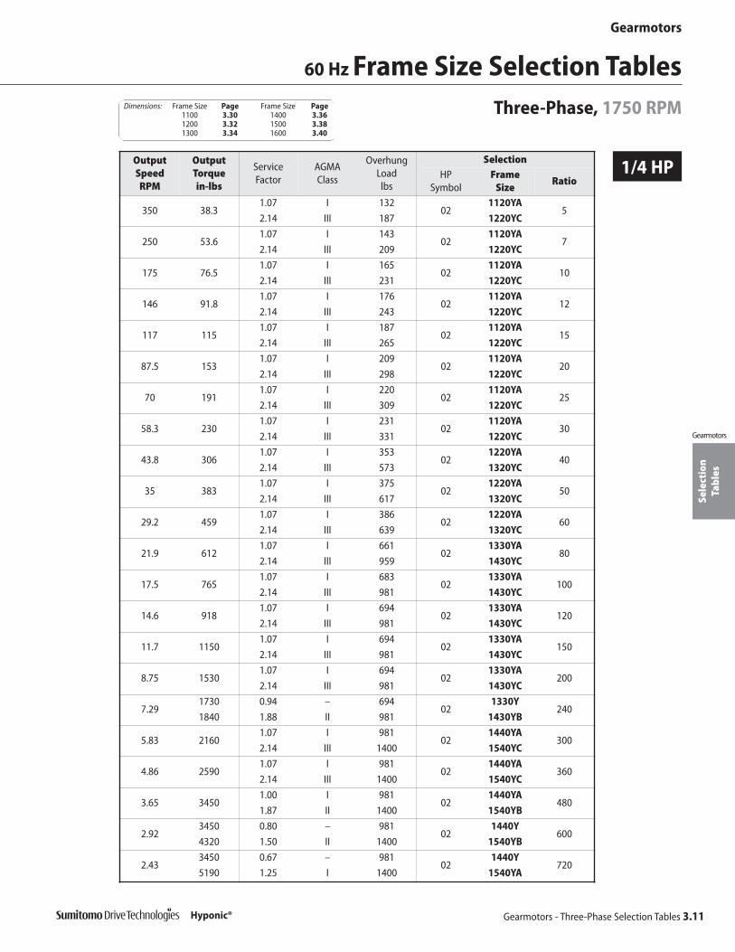
Sele
ctio
nTa
bles
Gearmotors
Gearmotors - Three-Phase Selection Tables 3.11
Gearmotors
Hyponic®
60 Hz Frame Size Selection TablesThree-Phase, 1750 RPM
1/4 HPOutputSpeed RPM
OutputTorque in-lbs
Service Factor
AGMA Class
OverhungLoad lbs
SelectionHP
SymbolFrame
SizeRatio
350 38.31.07 I 132
021120YA
52.14 III 187 1220YC
250 53.61.07 I 143
021120YA
72.14 III 209 1220YC
175 76.51.07 I 165
021120YA
102.14 III 231 1220YC
146 91.81.07 I 176
021120YA
122.14 III 243 1220YC
117 1151.07 I 187
021120YA
152.14 III 265 1220YC
87.5 1531.07 I 209
021120YA
202.14 III 298 1220YC
70 1911.07 I 220
021120YA
252.14 III 309 1220YC
58.3 2301.07 I 231
021120YA
302.14 III 331 1220YC
43.8 3061.07 I 353
021220YA
402.14 III 573 1320YC
35 3831.07 I 375
021220YA
502.14 III 617 1320YC
29.2 4591.07 I 386
021220YA
602.14 III 639 1320YC
21.9 6121.07 I 661
021330YA
802.14 III 959 1430YC
17.5 7651.07 I 683
021330YA
1002.14 III 981 1430YC
14.6 9181.07 I 694
021330YA
1202.14 III 981 1430YC
11.7 11501.07 I 694
021330YA
1502.14 III 981 1430YC
8.75 15301.07 I 694
021330YA
2002.14 III 981 1430YC
7.291730 0.94 – 694
021330Y
2401840 1.88 II 981 1430YB
5.83 21601.07 I 981
021440YA
3002.14 III 1400 1540YC
4.86 25901.07 I 981
021440YA
3602.14 III 1400 1540YC
3.65 34501.00 I 981
021440YA
4801.87 II 1400 1540YB
2.923450 0.80 – 981
021440Y
6004320 1.50 II 1400 1540YB
2.433450 0.67 – 981
021440Y
7205190 1.25 I 1400 1540YA
Dimensions: Frame Size Page Frame Size Page1100 3.30 1400 3.361200 3.32 1500 3.381300 3.34 1600 3.40

Sele
ctio
nTa
bles
Gearmotors
3.12 Gearmotors - Three-Phase Selection Tables
Gearmotors
Hyponic®
1/4 HP
Frame Size Selection Tables 60 Hz
Three-Phase, 1750 RPM
1/3 HP
OutputSpeed RPM
OutputTorque in-lbs
Service Factor
AGMA Class
OverhungLoad lbs
SelectionHP
SymbolFrame
SizeRatio
1.943450 0.53 – 981
021440Y
9006480 1.00 I 1400 1540YA
1.463450 0.40 – 981
021440Y
12006480 0.75 – 1400 1540Y
1.223450 0.33 – 981
021440Y
14406480 0.62 – 1400 1540Y
OutputSpeed RPM
OutputTorque in-lbs
Service Factor
AGMA Class
OverhungLoad lbs
Selection
HP Symbol
Frame Size
Ratio
350 51 1.61 II 187 03 1220YB 5
250 71.4 1.61 II 209 03 1220YB 7
175 102 1.61 II 231 03 1220YB 10
146 122 1.61 II 243 03 1220YB 12
117 153 1.61 II 265 03 1220YB 15
87.5 204 1.61 II 298 03 1220YB 20
70 255 1.61 II 309 03 1220YB 25
58.3 306 1.61 II 331 03 1220YB 30
43.8 408 1.61 II 573 03 1320YB 40
35 510 1.61 II 617 03 1320YB 50
29.2 612 1.61 II 639 03 1320YB 60
21.9 816 1.61 II 959 03 1430YB 80
17.5 1020 1.61 II 981 03 1430YB 100
14.6 1220 1.61 II 981 03 1430YB 120
11.7 1530 1.61 II 981 03 1430YB 150
8.75 2040 1.61 II 981 03 1430YB 200
7.29 2450 1.41 II 981 03 1430YB 240
5.83 2880 1.61 II 1400 03 1540YB 300
4.86 3460 1.61 II 1400 03 1540YB 360
3.65 4610 1.40 II 1400 03 1540YB 480
2.92 5760 1.12 I 1400 03 1540YA 600
2.43 6480 0.94 – 1400 03 1540Y 720
1.94 6480 0.75 – 1400 03 1540Y 900
1.46 6480 0.56 – 1400 03 1540Y 1200
1.22 6480 0.47 – 1400 03 1540Y 1440
Dimensions: Frame Size Page Frame Size Page1100 3.30 1400 3.361200 3.32 1500 3.381300 3.34 1600 3.40

Sele
ctio
nTa
bles
Gearmotors
Gearmotors - Three-Phase Selection Tables 3.13
Gearmotors
Hyponic®
1/2 HP
60 Hz Frame Size Selection TablesThree-Phase, 1750 RPM
OutputSpeed RPM
OutputTorque in-lbs
Service Factor
AGMA Class
OverhungLoad lbs
SelectionHP
SymbolFrame
SizeRatio
350 76.51.07 I 187
051220YA
52.14 III 309 1320YC
250 1071.07 I 209
051220YA
72.14 III 353 1320YC
175 1531.07 I 231
051220YA
102.14 III 386 1320YC
146 1841.07 I 243
051220YA
122.14 III 408 1320YC
117 2301.07 I 265
051220YA
152.14 III 441 1320YC
87.5 3061.07 I 298
051220YA
202.14 III 485 1320YC
70 3831.07 I 309
051220YA
252.14 III 507 1320YC
58.3 4591.07 I 331
051220YA
302.14 III 529 1320YC
43.8 6121.07 I 573
051320YA
402.14 III 860 1420YC
35 7651.07 I 617
051320YA
502.14 III 904 1420YC
29.2 9181.07 I 639
051320YA
602.14 III 937 1420YC
21.9 12201.07 I 959
051430YA
802.14 III 1380 1530YC
17.5 15301.07 I 981
051430YA
1002.14 III 1400 1530YC
14.6 18401.07 I 981
051430YA
1202.14 III 1400 1530YC
11.7 23001.07 I 981
051430YA
1502.14 III 1400 1530YC
8.75 30601.07 I 981
051430YA
2002.12 III 1400 1530YC
7.29 34500.94 – 981
051430Y
2401.76 II 1400 1530YB
5.83 43201.07 I 1400
051540YA
3002.14 III 2200 1640YC
4.86 51901.07 I 1400
051540YA
3602.14 III 2200 1640YC
3.656480 0.94 – 1400
051540Y
4806920 1.90 II 2200 1640YB
2.926480 0.75 – 1400
051540Y
6008640 1.52 II 2200 1640YB
2.436480 0.62 – 1400
051540Y
72010400 1.26 I 2200 1640YA
Dimensions: Frame Size Page Frame Size Page1100 3.30 1400 3.361200 3.32 1500 3.381300 3.34 1600 3.40

Sele
ctio
nTa
bles
Gearmotors
3.14 Gearmotors - Three-Phase Selection Tables
Gearmotors
Hyponic®
1/2 HP
3/4 HP
Frame Size Selection Tables 60 Hz
Three-Phase, 1750 RPM
OutputSpeed RPM
OutputTorque in-lbs
Service Factor
AGMA Class
OverhungLoad lbs
SelectionHP
SymbolFrame
SizeRatio
1.946480 0.50 – 1400
051540Y
90013000 1.01 I 2200 1640YA
1.466480 0.37 – 1400
051540Y
120013100 0.76 – 2200 1640Y
1.226480 0.31 – 1400
051540Y
144013100 0.63 – 2200 1640Y
OutputSpeed RPM
OutputTorque in-lbs
Service Factor
AGMA Class
OverhungLoad lbs
SelectionHP
SymbolFrame
SizeRatio
350 115 1.43 II 309 08 1320YB 5
250 161 1.43 II 353 08 1320YB 7
175 230 1.43 II 386 08 1320YB 10
146 276 1.43 II 408 08 1320YB 12
117 344 1.43 II 441 08 1320YB 15
87.5 459 1.43 II 485 08 1320YB 20
70 574 1.43 II 507 08 1320YB 25
58.3 689 1.43 II 529 08 1320YB 30
43.8 918 1.43 II 860 08 1420YB 40
35 1150 1.43 II 904 08 1420YB 50
29.2 1380 1.43 II 937 08 1420YB 60
21.9 1840 1.43 II 1380 08 1530YB 80
17.5 2300 1.43 II 1400 08 1530YB 100
14.6 2760 1.43 II 1400 08 1530YB 120
11.7 3440 1.43 II 1400 08 1530YB 150
8.75 4590 1.41 II 1400 08 1530YB 200
7.29 5510 1.18 I 1400 08 1530YA 240
5.83 6480 1.43 II 2200 08 1640YB 300
4.86 7780 1.43 II 2200 08 1640YB 360
3.65 10400 1.26 I 2200 08 1640YA 480
2.92 13000 1.01 I 2200 08 1640YA 600
2.43 13100 0.84 – 2200 08 1640Y 720
1.94 13100 0.67 – 2200 08 1640Y 900
1.46 13100 0.51 – 2200 08 1640Y 1200
1.22 13100 0.42 – 2200 08 1640Y 1440
Dimensions: Frame Size Page Frame Size Page1100 3.30 1400 3.361200 3.32 1500 3.381300 3.34 1600 3.40
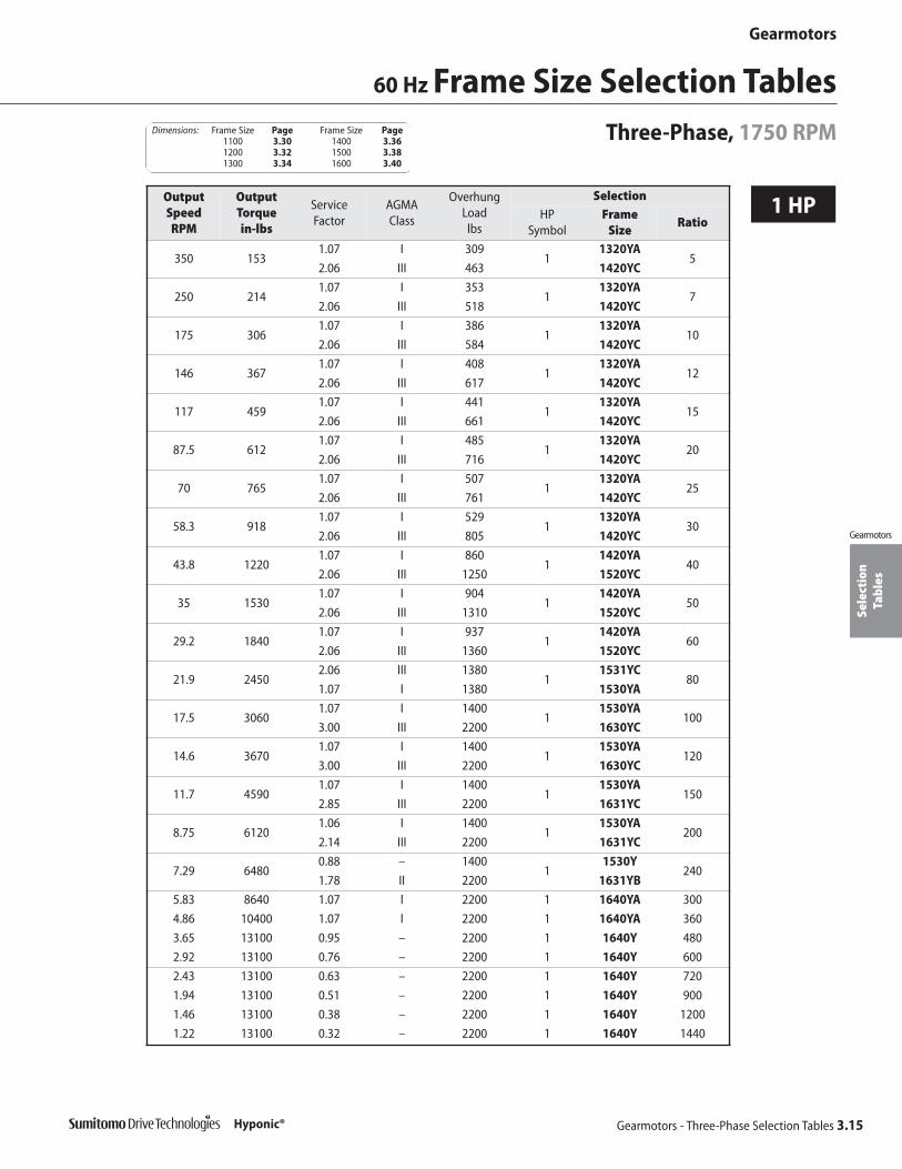
Sele
ctio
nTa
bles
Gearmotors
Gearmotors - Three-Phase Selection Tables 3.15
Gearmotors
Hyponic®
60 Hz Frame Size Selection TablesThree-Phase, 1750 RPM
1 HPOutputSpeed RPM
OutputTorque in-lbs
Service Factor
AGMA Class
OverhungLoad lbs
SelectionHP
SymbolFrame
SizeRatio
350 1531.07 I 309
11320YA
52.06 III 463 1420YC
250 2141.07 I 353
11320YA
72.06 III 518 1420YC
175 3061.07 I 386
11320YA
102.06 III 584 1420YC
146 3671.07 I 408
11320YA
122.06 III 617 1420YC
117 4591.07 I 441
11320YA
152.06 III 661 1420YC
87.5 6121.07 I 485
11320YA
202.06 III 716 1420YC
70 7651.07 I 507
11320YA
252.06 III 761 1420YC
58.3 9181.07 I 529
11320YA
302.06 III 805 1420YC
43.8 12201.07 I 860
11420YA
402.06 III 1250 1520YC
35 15301.07 I 904
11420YA
502.06 III 1310 1520YC
29.2 18401.07 I 937
11420YA
602.06 III 1360 1520YC
21.9 24502.06 III 1380
11531YC
801.07 I 1380 1530YA
17.5 30601.07 I 1400
11530YA
1003.00 III 2200 1630YC
14.6 36701.07 I 1400
11530YA
1203.00 III 2200 1630YC
11.7 45901.07 I 1400
11530YA
1502.85 III 2200 1631YC
8.75 61201.06 I 1400
11530YA
2002.14 III 2200 1631YC
7.29 64800.88 – 1400
11530Y
2401.78 II 2200 1631YB
5.83 8640 1.07 I 2200 1 1640YA 300
4.86 10400 1.07 I 2200 1 1640YA 360
3.65 13100 0.95 – 2200 1 1640Y 480
2.92 13100 0.76 – 2200 1 1640Y 600
2.43 13100 0.63 – 2200 1 1640Y 720
1.94 13100 0.51 – 2200 1 1640Y 900
1.46 13100 0.38 – 2200 1 1640Y 1200
1.22 13100 0.32 – 2200 1 1640Y 1440
Dimensions: Frame Size Page Frame Size Page1100 3.30 1400 3.361200 3.32 1500 3.381300 3.34 1600 3.40
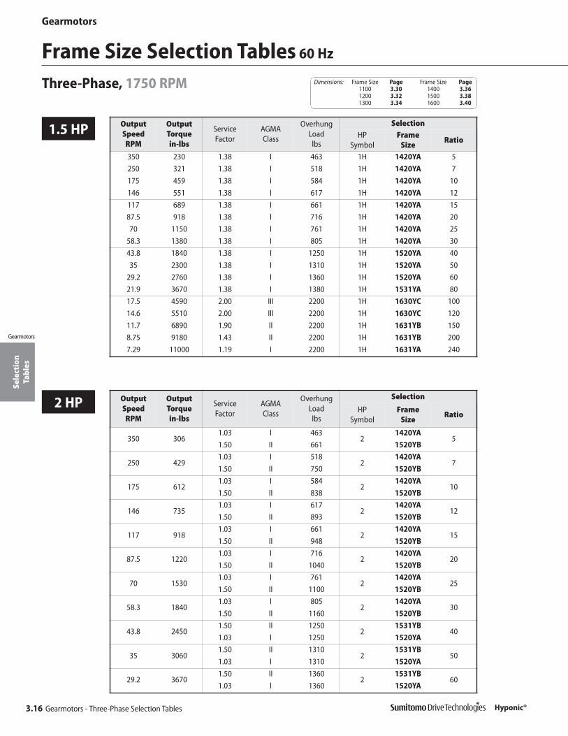
Sele
ctio
nTa
bles
Gearmotors
3.16 Gearmotors - Three-Phase Selection Tables
Gearmotors
Hyponic®
1.5 HP
Frame Size Selection Tables 60 Hz
Three-Phase, 1750 RPM
OutputSpeed RPM
OutputTorque in-lbs
Service Factor
AGMA Class
OverhungLoad lbs
SelectionHP
SymbolFrame
SizeRatio
350 230 1.38 I 463 1H 1420YA 5
250 321 1.38 I 518 1H 1420YA 7
175 459 1.38 I 584 1H 1420YA 10
146 551 1.38 I 617 1H 1420YA 12
117 689 1.38 I 661 1H 1420YA 15
87.5 918 1.38 I 716 1H 1420YA 20
70 1150 1.38 I 761 1H 1420YA 25
58.3 1380 1.38 I 805 1H 1420YA 30
43.8 1840 1.38 I 1250 1H 1520YA 40
35 2300 1.38 I 1310 1H 1520YA 50
29.2 2760 1.38 I 1360 1H 1520YA 60
21.9 3670 1.38 I 1380 1H 1531YA 80
17.5 4590 2.00 III 2200 1H 1630YC 100
14.6 5510 2.00 III 2200 1H 1630YC 120
11.7 6890 1.90 II 2200 1H 1631YB 150
8.75 9180 1.43 II 2200 1H 1631YB 200
7.29 11000 1.19 I 2200 1H 1631YA 240
2 HP OutputSpeed RPM
OutputTorque in-lbs
Service Factor
AGMA Class
OverhungLoad lbs
Selection
HP Symbol
Frame Size
Ratio
350 3061.03 I 463
21420YA
51.50 II 661 1520YB
250 4291.03 I 518
21420YA
71.50 II 750 1520YB
175 6121.03 I 584
21420YA
101.50 II 838 1520YB
146 7351.03 I 617
21420YA
121.50 II 893 1520YB
117 9181.03 I 661
21420YA
151.50 II 948 1520YB
87.5 12201.03 I 716
21420YA
201.50 II 1040 1520YB
70 15301.03 I 761
21420YA
251.50 II 1100 1520YB
58.3 18401.03 I 805
21420YA
301.50 II 1160 1520YB
43.8 24501.50 II 1250
21531YB
401.03 I 1250 1520YA
35 30601.50 II 1310
21531YB
501.03 I 1310 1520YA
29.2 36701.50 II 1360
21531YB
601.03 I 1360 1520YA
Dimensions: Frame Size Page Frame Size Page1100 3.30 1400 3.361200 3.32 1500 3.381300 3.34 1600 3.40

Sele
ctio
nTa
bles
Gearmotors
Gearmotors - Three-Phase Selection Tables 3.17
Gearmotors
Hyponic®
2 HP
3 HP
60 Hz Frame Size Selection TablesThree-Phase, 1750 RPM
OutputSpeed RPM
OutputTorque in-lbs
Service Factor
AGMA Class
OverhungLoad lbs
Selection
HP Symbol
Frame Size
Ratio
21.9 49001.03 I 1380
21531YA
801.50 II 2170 1630YB
17.5 6120 1.50 II 2200 2 1630YB 100
14.6 7350 1.50 II 2200 2 1630YB 120
11.7 9180 1.43 II 2200 2 1631YB 150
8.75 12200 1.07 I 2200 2 1631YA 200
7.29 13100 0.89 – 2200 2 1631Y 240
OutputSpeed RPM
OutputTorque in-lbs
Service Factor
AGMA Class
OverhungLoad lbs
SelectionHP
SymbolFrame
SizeRatio
350 4591.00 I 661
31520YA
51.67 II 661 1521YB
250 6431.00 I 750
31520YA
71.67 II 750 1521YB
175 9181.00 I 838
31520YA
101.67 II 838 1521YB
146 11001.00 I 893
31520YA
121.67 II 893 1521YB
117 13801.00 I 948
31520YA
151.67 II 948 1521YB
87.5 18401.00 I 1040
31520YA
201.67 II 1040 1521YB
70 23001.00 I 1100
31520YA
251.67 II 1100 1521YB
58.3 27601.00 I 1160
31520YA
301.67 II 1820 1632YB
43.8 36701.00 I 1250
31531YA
401.67 II 1910 1632YB
35 45901.00 I 1310
31531YA
501.67 II 2000 1632YB
29.2 55101.00 I 1360
31531YA
601.67 II 2060 1632YB
21.9 7350 1.00 I 2170 3 1630YA 80
17.5 9180 1.00 I 2200 3 1630YA 100
14.6 11000 1.00 I 2200 3 1630YA 120
11.7 13100 0.95 – 2200 3 1631Y 150
8.75 13100 0.71 – 2200 3 1631Y 200
7.29 13100 0.59 – 2200 3 1631Y 240
Dimensions: Frame Size Page Frame Size Page1100 3.30 1400 3.361200 3.32 1500 3.381300 3.34 1600 3.40
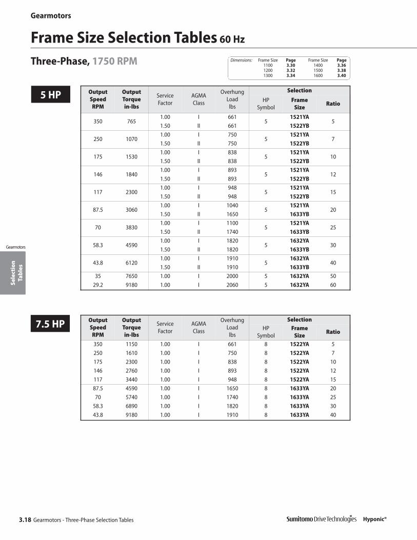
Sele
ctio
nTa
bles
Gearmotors
3.18 Gearmotors - Three-Phase Selection Tables
Gearmotors
Hyponic®
5 HP
Frame Size Selection Tables 60 Hz
Three-Phase, 1750 RPM
OutputSpeed RPM
OutputTorque in-lbs
Service Factor
AGMA Class
OverhungLoad lbs
Selection
HP Symbol
Frame Size
Ratio
350 7651.00 I 661
51521YA
51.50 II 661 1522YB
250 10701.00 I 750
51521YA
71.50 II 750 1522YB
175 15301.00 I 838
51521YA
101.50 II 838 1522YB
146 18401.00 I 893
51521YA
121.50 II 893 1522YB
117 23001.00 I 948
51521YA
151.50 II 948 1522YB
87.5 30601.00 I 1040
51521YA
201.50 II 1650 1633YB
70 38301.00 I 1100
51521YA
251.50 II 1740 1633YB
58.3 45901.00 I 1820
51632YA
301.50 II 1820 1633YB
43.8 61201.00 I 1910
51632YA
401.50 II 1910 1633YB
35 7650 1.00 I 2000 5 1632YA 50
29.2 9180 1.00 I 2060 5 1632YA 60
7.5 HP OutputSpeed RPM
OutputTorque in-lbs
Service Factor
AGMA Class
OverhungLoad lbs
SelectionHP
SymbolFrame
SizeRatio
350 1150 1.00 I 661 8 1522YA 5
250 1610 1.00 I 750 8 1522YA 7
175 2300 1.00 I 838 8 1522YA 10
146 2760 1.00 I 893 8 1522YA 12
117 3440 1.00 I 948 8 1522YA 15
87.5 4590 1.00 I 1650 8 1633YA 20
70 5740 1.00 I 1740 8 1633YA 25
58.3 6890 1.00 I 1820 8 1633YA 30
43.8 9180 1.00 I 1910 8 1633YA 40
Dimensions: Frame Size Page Frame Size Page1100 3.30 1400 3.361200 3.32 1500 3.381300 3.34 1600 3.40
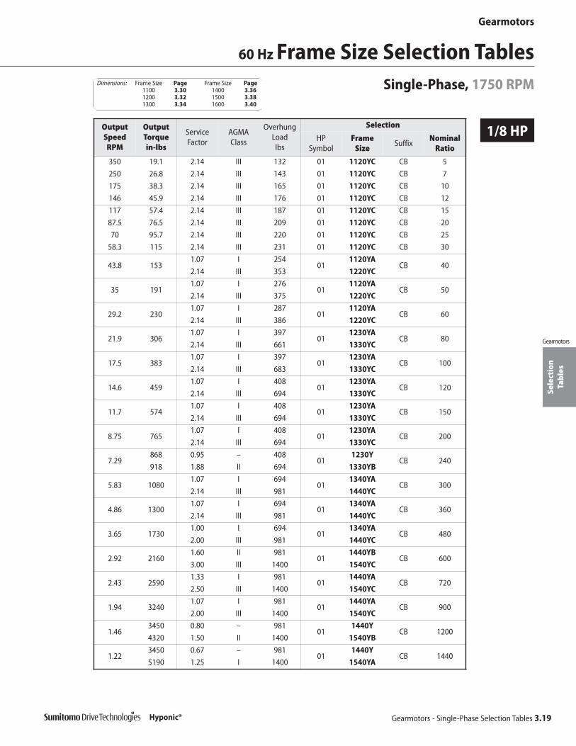
Sele
ctio
nTa
bles
Gearmotors
Gearmotors - Single-Phase Selection Tables 3.19
Gearmotors
Hyponic®
1/8 HP
60 Hz Frame Size Selection TablesSingle-Phase, 1750 RPM
OutputSpeed RPM
OutputTorque in-lbs
ServiceFactor
AGMA Class
OverhungLoad lbs
Selection
HP Symbol
Frame Size
SuffixNominal
Ratio
350 19.1 2.14 III 132 01 1120YC CB 5
250 26.8 2.14 III 143 01 1120YC CB 7
175 38.3 2.14 III 165 01 1120YC CB 10
146 45.9 2.14 III 176 01 1120YC CB 12
117 57.4 2.14 III 187 01 1120YC CB 15
87.5 76.5 2.14 III 209 01 1120YC CB 20
70 95.7 2.14 III 220 01 1120YC CB 25
58.3 115 2.14 III 231 01 1120YC CB 30
43.8 1531.07 I 254
011120YA
CB 402.14 III 353 1220YC
35 1911.07 I 276
011120YA
CB 502.14 III 375 1220YC
29.2 2301.07 I 287
011120YA
CB 602.14 III 386 1220YC
21.9 3061.07 I 397
011230YA
CB 802.14 III 661 1330YC
17.5 3831.07 I 397
011230YA
CB 1002.14 III 683 1330YC
14.6 4591.07 I 408
011230YA
CB 1202.14 III 694 1330YC
11.7 5741.07 I 408
011230YA
CB 1502.14 III 694 1330YC
8.75 7651.07 I 408
011230YA
CB 2002.14 III 694 1330YC
7.29868 0.95 – 408
011230Y
CB 240918 1.88 II 694 1330YB
5.83 10801.07 I 694
011340YA
CB 3002.14 III 981 1440YC
4.86 13001.07 I 694
011340YA
CB 3602.14 III 981 1440YC
3.65 17301.00 I 694
011340YA
CB 4802.00 III 981 1440YC
2.92 21601.60 II 981
011440YB
CB 6003.00 III 1400 1540YC
2.43 25901.33 I 981
011440YA
CB 7202.50 III 1400 1540YC
1.94 32401.07 I 981
011440YA
CB 9002.00 III 1400 1540YC
1.463450 0.80 – 981
011440Y
CB 12004320 1.50 II 1400 1540YB
1.223450 0.67 – 981
011440Y
CB 14405190 1.25 I 1400 1540YA
Dimensions: Frame Size Page Frame Size Page1100 3.30 1400 3.361200 3.32 1500 3.381300 3.34 1600 3.40
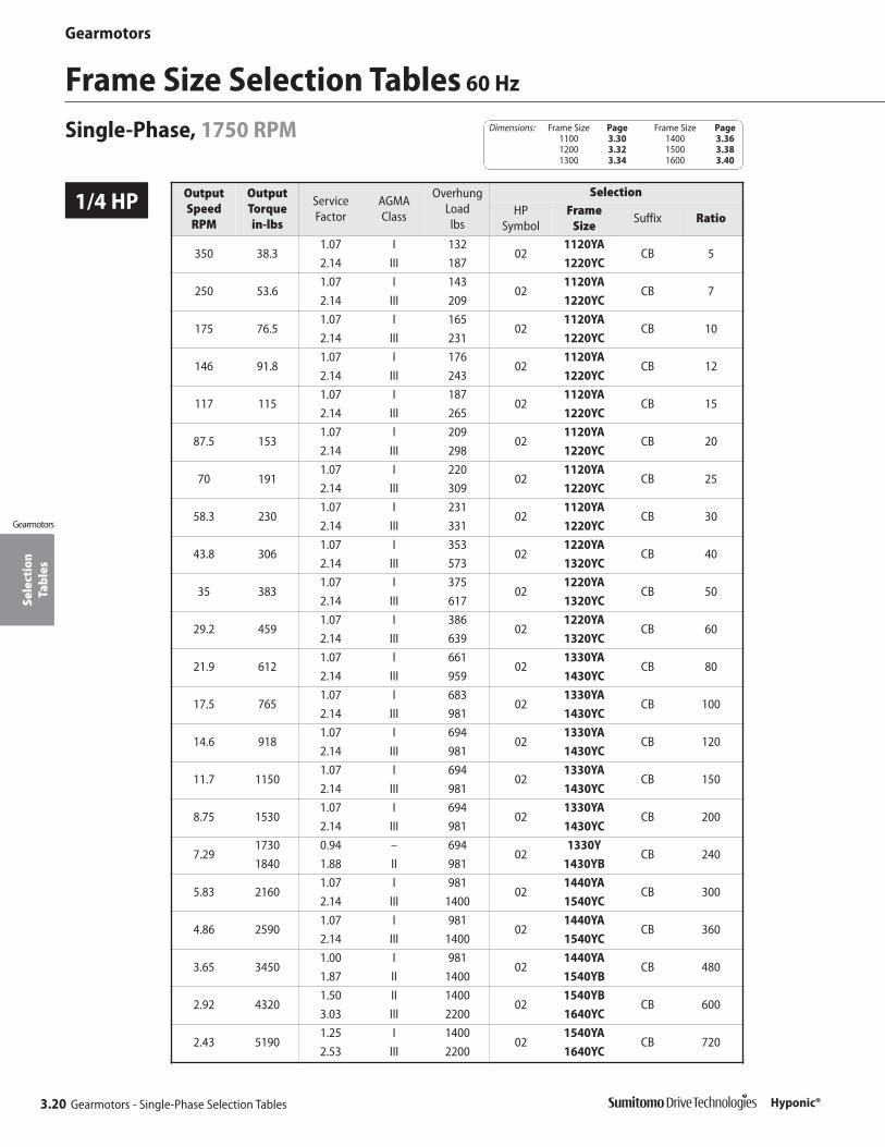
Sele
ctio
nTa
bles
Gearmotors
3.20 Gearmotors - Single-Phase Selection Tables
Gearmotors
Hyponic®
1/4 HP
Frame Size Selection Tables 60 Hz
Single-Phase, 1750 RPM
OutputSpeed RPM
OutputTorque in-lbs
Service Factor
AGMA Class
OverhungLoad lbs
SelectionHP
SymbolFrame
SizeSuffix Ratio
350 38.31.07 I 132
021120YA
CB 52.14 III 187 1220YC
250 53.61.07 I 143
021120YA
CB 72.14 III 209 1220YC
175 76.51.07 I 165
021120YA
CB 102.14 III 231 1220YC
146 91.81.07 I 176
021120YA
CB 122.14 III 243 1220YC
117 1151.07 I 187
021120YA
CB 152.14 III 265 1220YC
87.5 1531.07 I 209
021120YA
CB 202.14 III 298 1220YC
70 1911.07 I 220
021120YA
CB 252.14 III 309 1220YC
58.3 2301.07 I 231
021120YA
CB 302.14 III 331 1220YC
43.8 3061.07 I 353
021220YA
CB 402.14 III 573 1320YC
35 3831.07 I 375
021220YA
CB 502.14 III 617 1320YC
29.2 4591.07 I 386
021220YA
CB 602.14 III 639 1320YC
21.9 6121.07 I 661
021330YA
CB 802.14 III 959 1430YC
17.5 7651.07 I 683
021330YA
CB 1002.14 III 981 1430YC
14.6 9181.07 I 694
021330YA
CB 1202.14 III 981 1430YC
11.7 11501.07 I 694
021330YA
CB 1502.14 III 981 1430YC
8.75 15301.07 I 694
021330YA
CB 2002.14 III 981 1430YC
7.291730 0.94 – 694
021330Y
CB 2401840 1.88 II 981 1430YB
5.83 21601.07 I 981
021440YA
CB 3002.14 III 1400 1540YC
4.86 25901.07 I 981
021440YA
CB 3602.14 III 1400 1540YC
3.65 34501.00 I 981
021440YA
CB 4801.87 II 1400 1540YB
2.92 43201.50 II 1400
021540YB
CB 6003.03 III 2200 1640YC
2.43 51901.25 I 1400
021540YA
CB 7202.53 III 2200 1640YC
Dimensions: Frame Size Page Frame Size Page1100 3.30 1400 3.361200 3.32 1500 3.381300 3.34 1600 3.40

Sele
ctio
nTa
bles
Gearmotors
Gearmotors - Single-Phase Selection Tables 3.21
Gearmotors
Hyponic®
1/4 HP
60 Hz Frame Size Selection TablesSingle-Phase, 1750 RPM
OutputSpeed RPM
OutputTorque in-lbs
Service Factor
AGMA Class
OverhungLoad lbs
SelectionHP
SymbolFrame
SizeSuffix Ratio
1.94 64801.00 I 1400
021540YA
CB 9002.02 III 2200 1640YC
1.466480 0.75 – 1400
021540Y
CB 12008640 1.52 II 2200 1640YB
1.226480 0.62 – 1400
021540Y
CB 144010400 1.26 I 2200 1640YA
1/2 HPOutputSpeed RPM
OutputTorque in-lbs
Service Factor
AGMA Class
OverhungLoad lbs
SelectionHP
SymbolFrame
SizeSuffix Ratio
350 76.5 2.14 III 309 05 1320YC CB 5
250 107 2.14 III 353 05 1320YC CB 7
175 153 2.14 III 386 05 1320YC CB 10
146 184 2.14 III 408 05 1320YC CB 12
117 230 2.14 III 441 05 1320YC CB 15
87.5 306 2.14 III 485 05 1320YC CB 20
70 383 2.14 III 507 05 1320YC CB 25
58.3 459 2.14 III 529 05 1320YC CB 30
43.8 612 2.14 III 860 05 1420YC CB 40
35 765 2.14 III 904 05 1420YC CB 50
29.2 918 2.14 III 937 05 1420YC CB 60
21.9 1220 2.14 III 1380 05 1530YC CB 80
17.5 1530 2.14 III 1400 05 1530YC CB 100
14.6 1840 2.14 III 1400 05 1530YC CB 120
11.7 2300 2.14 III 1400 05 1530YC CB 150
8.75 3060 2.12 III 1400 05 1530YC CB 200
7.29 3670 1.76 II 1400 05 1530YB CB 240
5.83 4320 2.14 III 2200 05 1640YC CB 300
4.86 5190 2.14 III 2200 05 1640YC CB 360
3.65 6920 1.90 II 2200 05 1640YB CB 480
2.92 8640 1.52 II 2200 05 1640YB CB 600
2.43 10400 1.26 I 2200 05 1640YA CB 720
1.94 13000 1.01 I 2200 05 1640YA CB 900
1.46 13100 0.76 – 2200 05 1640Y CB 1200
1.22 13100 0.63 – 2200 05 1640Y CB 1440
Dimensions: Frame Size Page Frame Size Page1100 3.30 1400 3.361200 3.32 1500 3.381300 3.34 1600 3.40
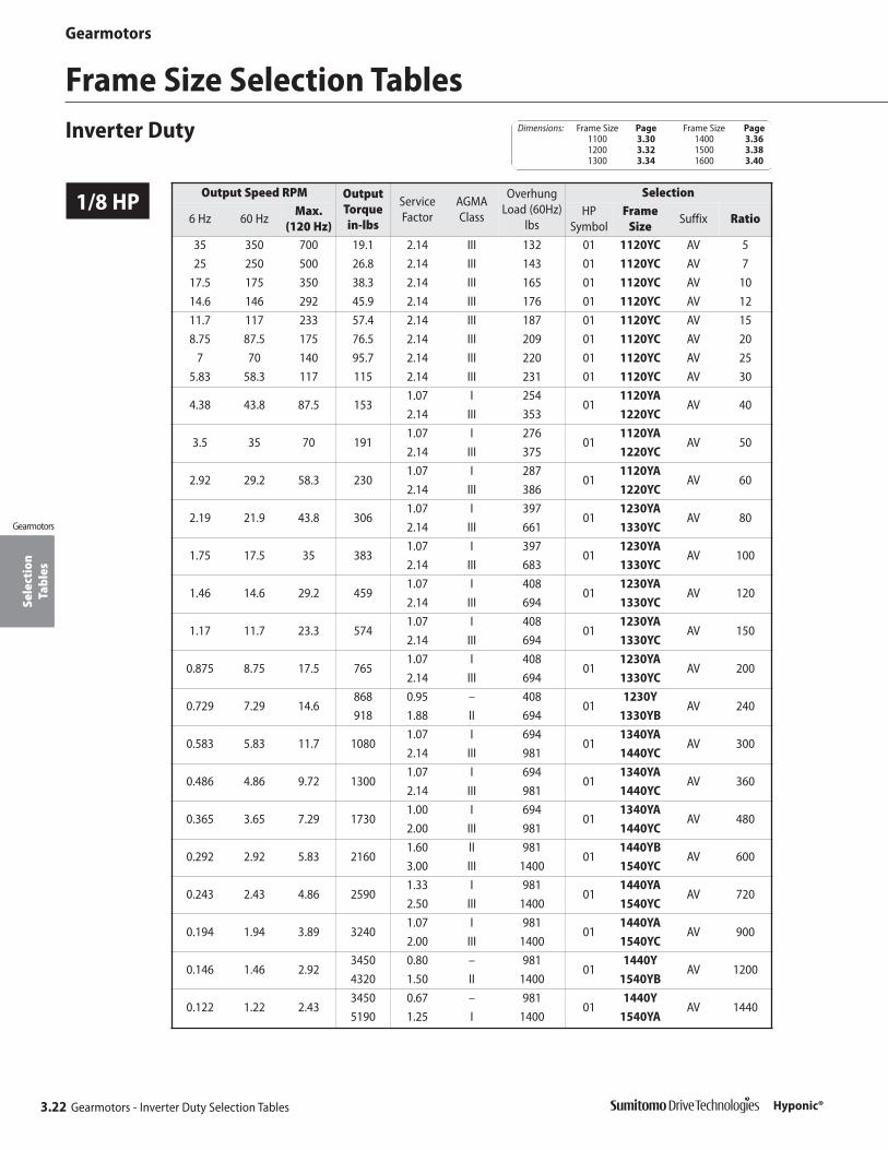
Sele
ctio
nTa
bles
Gearmotors
3.22 Gearmotors - Inverter Duty Selection Tables
Gearmotors
Hyponic®
1/8 HP
Frame Size Selection TablesInverter Duty
Output Speed RPM OutputTorque in-lbs
ServiceFactor
AGMAClass
OverhungLoad (60Hz)
lbs
Selection
6 Hz 60 HzMax.
(120 Hz)HP
SymbolFrame
SizeSuffix Ratio
35 350 700 19.1 2.14 III 132 01 1120YC AV 5
25 250 500 26.8 2.14 III 143 01 1120YC AV 7
17.5 175 350 38.3 2.14 III 165 01 1120YC AV 10
14.6 146 292 45.9 2.14 III 176 01 1120YC AV 12
11.7 117 233 57.4 2.14 III 187 01 1120YC AV 15
8.75 87.5 175 76.5 2.14 III 209 01 1120YC AV 20
7 70 140 95.7 2.14 III 220 01 1120YC AV 25
5.83 58.3 117 115 2.14 III 231 01 1120YC AV 30
4.38 43.8 87.5 1531.07 I 254
011120YA
AV 402.14 III 353 1220YC
3.5 35 70 1911.07 I 276
011120YA
AV 502.14 III 375 1220YC
2.92 29.2 58.3 2301.07 I 287
011120YA
AV 602.14 III 386 1220YC
2.19 21.9 43.8 3061.07 I 397
011230YA
AV 802.14 III 661 1330YC
1.75 17.5 35 3831.07 I 397
011230YA
AV 1002.14 III 683 1330YC
1.46 14.6 29.2 4591.07 I 408
011230YA
AV 1202.14 III 694 1330YC
1.17 11.7 23.3 5741.07 I 408
011230YA
AV 1502.14 III 694 1330YC
0.875 8.75 17.5 7651.07 I 408
011230YA
AV 2002.14 III 694 1330YC
0.729 7.29 14.6868 0.95 – 408
011230Y
AV 240918 1.88 II 694 1330YB
0.583 5.83 11.7 10801.07 I 694
011340YA
AV 3002.14 III 981 1440YC
0.486 4.86 9.72 13001.07 I 694
011340YA
AV 3602.14 III 981 1440YC
0.365 3.65 7.29 17301.00 I 694
011340YA
AV 4802.00 III 981 1440YC
0.292 2.92 5.83 21601.60 II 981
011440YB
AV 6003.00 III 1400 1540YC
0.243 2.43 4.86 25901.33 I 981
011440YA
AV 7202.50 III 1400 1540YC
0.194 1.94 3.89 32401.07 I 981
011440YA
AV 9002.00 III 1400 1540YC
0.146 1.46 2.923450 0.80 – 981
011440Y
AV 12004320 1.50 II 1400 1540YB
0.122 1.22 2.433450 0.67 – 981
011440Y
AV 14405190 1.25 I 1400 1540YA
Dimensions: Frame Size Page Frame Size Page1100 3.30 1400 3.361200 3.32 1500 3.381300 3.34 1600 3.40
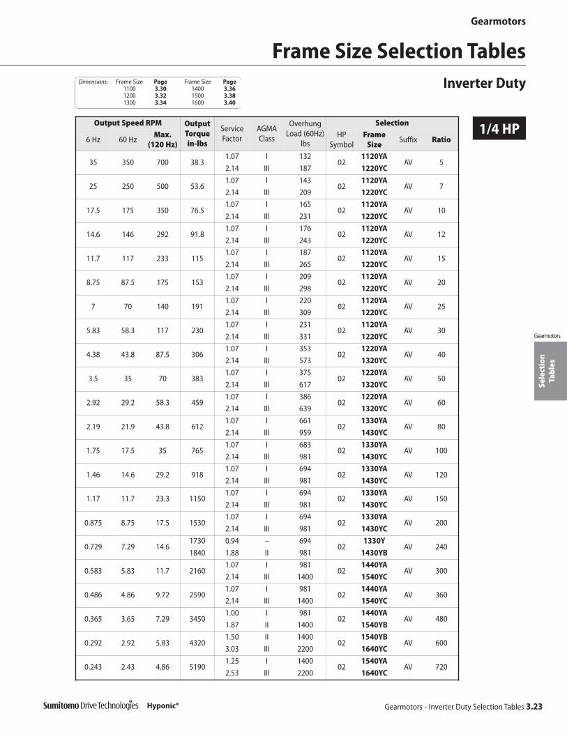
Sele
ctio
nTa
bles
Gearmotors
Gearmotors - Inverter Duty Selection Tables 3.23
Gearmotors
Hyponic®
1/4 HP
Frame Size Selection TablesInverter Duty
Output Speed RPM OutputTorque in-lbs
ServiceFactor
AGMAClass
OverhungLoad (60Hz)
lbs
Selection
6 Hz 60 HzMax.
(120 Hz)HP
SymbolFrame
SizeSuffix Ratio
35 350 700 38.31.07 I 132
021120YA
AV 52.14 III 187 1220YC
25 250 500 53.61.07 I 143
021120YA
AV 72.14 III 209 1220YC
17.5 175 350 76.51.07 I 165
021120YA
AV 102.14 III 231 1220YC
14.6 146 292 91.81.07 I 176
021120YA
AV 122.14 III 243 1220YC
11.7 117 233 1151.07 I 187
021120YA
AV 152.14 III 265 1220YC
8.75 87.5 175 1531.07 I 209
021120YA
AV 202.14 III 298 1220YC
7 70 140 1911.07 I 220
021120YA
AV 252.14 III 309 1220YC
5.83 58.3 117 2301.07 I 231
021120YA
AV 302.14 III 331 1220YC
4.38 43.8 87.5 3061.07 I 353
021220YA
AV 402.14 III 573 1320YC
3.5 35 70 3831.07 I 375
021220YA
AV 502.14 III 617 1320YC
2.92 29.2 58.3 4591.07 I 386
021220YA
AV 602.14 III 639 1320YC
2.19 21.9 43.8 6121.07 I 661
021330YA
AV 802.14 III 959 1430YC
1.75 17.5 35 7651.07 I 683
021330YA
AV 1002.14 III 981 1430YC
1.46 14.6 29.2 9181.07 I 694
021330YA
AV 1202.14 III 981 1430YC
1.17 11.7 23.3 11501.07 I 694
021330YA
AV 1502.14 III 981 1430YC
0.875 8.75 17.5 15301.07 I 694
021330YA
AV 2002.14 III 981 1430YC
0.729 7.29 14.61730 0.94 – 694
021330Y
AV 2401840 1.88 II 981 1430YB
0.583 5.83 11.7 21601.07 I 981
021440YA
AV 3002.14 III 1400 1540YC
0.486 4.86 9.72 25901.07 I 981
021440YA
AV 3602.14 III 1400 1540YC
0.365 3.65 7.29 34501.00 I 981
021440YA
AV 4801.87 II 1400 1540YB
0.292 2.92 5.83 43201.50 II 1400
021540YB
AV 6003.03 III 2200 1640YC
0.243 2.43 4.86 51901.25 I 1400
021540YA
AV 7202.53 III 2200 1640YC
Dimensions: Frame Size Page Frame Size Page1100 3.30 1400 3.361200 3.32 1500 3.381300 3.34 1600 3.40
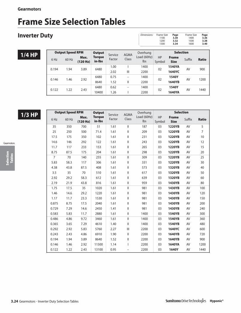
Sele
ctio
nTa
bles
Gearmotors
3.24 Gearmotors - Inverter Duty Selection Tables
Gearmotors
Hyponic®
1/4 HP
Frame Size Selection TablesInverter Duty
Output Speed RPM OutputTorque in-lbs
ServiceFactor
AGMAClass
OverhungLoad (60Hz)
lbs
Selection
6 Hz 60 HzMax.
(120 Hz)HP
SymbolFrame
SizeSuffix Ratio
0.194 1.94 3.89 64801.00 I 1400
021540YA
AV 9002.02 III 2200 1640YC
0.146 1.46 2.926480 0.75 – 1400
021540Y
AV 12008640 1.52 II 2200 1640YB
0.122 1.22 2.436480 0.62 – 1400
021540Y
AV 144010400 1.26 I 2200 1640YA
1/3 HP Output Speed RPM OutputTorque in-lbs
ServiceFactor
AGMAClass
OverhungLoad (60Hz)
lbs
Selection
6 Hz 60 HzMax.
(120 Hz)HP
SymbolFrame
SizeSuffix Ratio
35 350 700 51 1.61 II 187 03 1220YB AV 5
25 250 500 71.4 1.61 II 209 03 1220YB AV 7
17.5 175 350 102 1.61 II 231 03 1220YB AV 10
14.6 146 292 122 1.61 II 243 03 1220YB AV 12
11.7 117 233 153 1.61 II 265 03 1220YB AV 15
8.75 87.5 175 204 1.61 II 298 03 1220YB AV 20
7 70 140 255 1.61 II 309 03 1220YB AV 25
5.83 58.3 117 306 1.61 II 331 03 1220YB AV 30
4.38 43.8 87.5 408 1.61 II 573 03 1320YB AV 40
3.5 35 70 510 1.61 II 617 03 1320YB AV 50
2.92 29.2 58.3 612 1.61 II 639 03 1320YB AV 60
2.19 21.9 43.8 816 1.61 II 959 03 1430YB AV 80
1.75 17.5 35 1020 1.61 II 981 03 1430YB AV 100
1.46 14.6 29.2 1220 1.61 II 981 03 1430YB AV 120
1.17 11.7 23.3 1530 1.61 II 981 03 1430YB AV 150
0.875 8.75 17.5 2040 1.61 II 981 03 1430YB AV 200
0.729 7.29 14.6 2450 1.41 II 981 03 1430YB AV 240
0.583 5.83 11.7 2880 1.61 II 1400 03 1540YB AV 300
0.486 4.86 9.72 3460 1.61 II 1400 03 1540YB AV 360
0.365 3.65 7.29 4610 1.40 II 1400 03 1540YB AV 480
0.292 2.92 5.83 5760 2.27 III 2200 03 1640YC AV 600
0.243 2.43 4.86 6910 1.90 II 2200 03 1640YB AV 720
0.194 1.94 3.89 8640 1.52 II 2200 03 1640YB AV 900
0.146 1.46 2.92 11500 1.14 I 2200 03 1640YA AV 1200
0.122 1.22 2.43 13100 0.95 – 2200 03 1640Y AV 1440
Dimensions: Frame Size Page Frame Size Page1100 3.30 1400 3.361200 3.32 1500 3.381300 3.34 1600 3.40

Sele
ctio
nTa
bles
Gearmotors
Gearmotors - Inverter Duty Selection Tables 3.25
Gearmotors
1/2 HP
3/4 HP
Frame Size Selection TablesInverter Duty
Hyponic®
Output Speed RPM OutputTorque in-lbs
ServiceFactor
AGMAClass
OverhungLoad (60Hz)
lbs
Selection
6 Hz 60 HzMax.(120)
HPSymbol
Frame Size
Suffix Ratio
35 350 700 76.5 2.14 III 309 05 1320YC AV 525 250 500 107 2.14 III 353 05 1320YC AV 7
17.5 175 350 153 2.14 III 386 05 1320YC AV 1014.6 146 292 184 2.14 III 408 05 1320YC AV 1211.7 117 233 230 2.14 III 441 05 1320YC AV 158.75 87.5 175 306 2.14 III 485 05 1320YC AV 20
7 70 140 383 2.14 III 507 05 1320YC AV 255.83 58.3 117 459 2.14 III 529 05 1320YC AV 304.38 43.8 87.5 612 2.14 III 860 05 1420YC AV 403.5 35 70 765 2.14 III 904 05 1420YC AV 50
2.92 29.2 58.3 918 2.14 III 937 05 1420YC AV 602.19 21.9 43.8 1220 2.14 III 1380 05 1530YC AV 801.75 17.5 35 1530 2.14 III 1400 05 1530YC AV 1001.46 14.6 29.2 1840 2.14 III 1400 05 1530YC AV 1201.17 11.7 23.3 2300 2.14 III 1400 05 1530YC AV 150
0.875 8.75 17.5 3060 2.12 III 1400 05 1530YC AV 2000.729 7.29 14.6 3670 1.76 II 1400 05 1530YB AV 2400.583 5.83 11.7 4320 2.14 III 2200 05 1640YC AV 3000.486 4.86 9.72 5190 2.14 III 2200 05 1640YC AV 3600.365 3.65 7.29 6920 1.90 II 2200 05 1640YB AV 4800.292 2.92 5.83 8640 1.52 II 2200 05 1640YB AV 6000.243 2.43 4.86 10400 1.26 I 2200 05 1640YA AV 7200.194 1.94 3.89 13000 1.01 I 2200 05 1640YA AV 9000.146 1.46 2.92 13100 0.76 – 2200 05 1640Y AV 12000.122 1.22 2.43 13100 0.63 – 2200 05 1640Y AV 1440
Output Speed RPM OutputTorque in-lbs
ServiceFactor
AGMAClass
OverhungLoad (60Hz)
lbs
Selection
6 Hz 60 HzMax.(120)
HPSymbol
Frame Size
Suffix Ratio
35 350 700 115 2.75 III 463 08 1420YC AV 525 250 500 161 2.75 III 518 08 1420YC AV 7
17.5 175 350 230 2.75 III 584 08 1420YC AV 1014.6 146 292 276 2.75 III 617 08 1420YC AV 1211.7 117 233 344 2.75 III 661 08 1420YC AV 158.75 87.5 175 459 2.75 III 716 08 1420YC AV 20
7 70 140 574 2.75 III 761 08 1420YC AV 255.83 58.3 117 689 2.75 III 805 08 1420YC AV 304.38 43.8 87.5 918 2.75 III 1250 08 1520YC AV 403.5 35 70 1150 2.75 III 1310 08 1520YC AV 50
2.92 29.2 58.3 1380 2.75 III 1360 08 1520YC AV 602.19 21.9 43.8 1840 2.75 III 1380 08 1531YC AV 801.75 17.5 35 2300 4.00 III 2200 08 1630YC AV 1001.46 14.6 29.2 2760 4.00 III 2200 08 1630YC AV 1201.17 11.7 23.3 3440 3.81 III 2200 08 1631YC AV 150
0.875 8.75 17.5 4590 2.85 III 2200 08 1631YC AV 2000.729 7.29 14.6 5510 2.38 III 2200 08 1631YC AV 240
Dimensions: Frame Size Page Frame Size Page1100 3.30 1400 3.361200 3.32 1500 3.381300 3.34 1600 3.40

Sele
ctio
nTa
bles
Gearmotors
3.26 Gearmotors - Inverter Duty Selection Tables
Gearmotors
Hyponic®
1 HP
Frame Size Selection TablesInverter Duty
Output Speed RPM OutputTorque in-lbs
ServiceFactor
AGMAClass
OverhungLoad (60Hz)
lbs
Selection
6 Hz 60 HzMax.
(120 Hz)HP
SymbolFrame
SizeSuffix Ratio
35 350 700 153 2.06 III 463 1 1420YC AV 5
25 250 500 214 2.06 III 518 1 1420YC AV 7
17.5 175 350 306 2.06 III 584 1 1420YC AV 10
14.6 146 292 367 2.06 III 617 1 1420YC AV 12
11.7 117 233 459 2.06 III 661 1 1420YC AV 15
8.75 87.5 175 612 2.06 III 716 1 1420YC AV 20
7 70 140 765 2.06 III 761 1 1420YC AV 25
5.83 58.3 117 918 2.06 III 805 1 1420YC AV 30
4.38 43.8 87.5 1220 2.06 III 1250 1 1520YC AV 40
3.5 35 70 1530 2.06 III 1310 1 1520YC AV 50
2.92 29.2 58.3 1840 2.06 III 1360 1 1520YC AV 60
2.19 21.9 43.8 2450 2.06 III 1380 1 1531YC AV 80
1.75 17.5 35 3060 3.00 III 2200 1 1630YC AV 100
1.46 14.6 29.2 3670 3.00 III 2200 1 1630YC AV 120
1.17 11.7 23.3 4590 2.85 III 2200 1 1631YC AV 150
0.875 8.75 17.5 6120 2.14 III 2200 1 1631YC AV 200
0.729 7.29 14.6 7350 1.78 II 2200 1 1631YB AV 240
Output Speed RPM OutputTorque in-lbs
ServiceFactor
AGMAClass
OverhungLoad (60Hz)
lbs
Selection
6 Hz 60 HzMax.
(120 Hz)HP
SymbolFrame
SizeSuffix Ratio
35 350 700 230 2.00 III 661 1H 1520YC AV 5
25 250 500 321 2.00 III 750 1H 1520YC AV 7
17.5 175 350 459 2.00 III 838 1H 1520YC AV 10
14.6 146 292 551 2.00 III 893 1H 1520YC AV 12
11.7 117 233 689 2.00 III 948 1H 1520YC AV 15
8.75 87.5 175 918 2.00 III 1040 1H 1520YC AV 20
7 70 140 1150 2.00 III 1100 1H 1520YC AV 25
5.83 58.3 117 1380 2.00 III 1160 1H 1520YC AV 30
4.38 43.8 87.5 1840 2.00 III 1250 1H 1531YC AV 40
3.5 35 70 2300 2.00 III 1310 1H 1531YC AV 50
2.92 29.2 58.3 2760 2.00 III 1360 1H 1531YC AV 60
2.19 21.9 43.8 3670 2.00 III 2170 1H 1630YC AV 80
1.75 17.5 35 4590 2.00 III 2200 1H 1630YC AV 100
1.46 14.6 29.2 5510 2.00 III 2200 1H 1630YC AV 120
1.17 11.7 23.3 6890 1.90 II 2200 1H 1631YB AV 150
0.875 8.75 17.5 9180 1.43 II 2200 1H 1631YB AV 200
0.729 7.29 14.6 11000 1.19 I 2200 1H 1631YA AV 240
1.5 HP
Dimensions: Frame Size Page Frame Size Page1100 3.30 1400 3.361200 3.32 1500 3.381300 3.34 1600 3.40
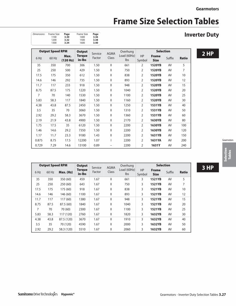
Sele
ctio
nTa
bles
Gearmotors
Gearmotors - Inverter Duty Selection Tables 3.27
Gearmotors
Hyponic®
2 HP
Frame Size Selection TablesInverter Duty
Output Speed RPM OutputTorque in-lbs
ServiceFactor
AGMAClass
OverhungLoad (60Hz)
lbs
Selection
6 Hz 60 HzMax.
(120 Hz)HP
SymbolFrame
SizeSuffix Ratio
35 350 700 306 1.50 II 661 2 1520YB AV 5
25 250 500 429 1.50 II 750 2 1520YB AV 7
17.5 175 350 612 1.50 II 838 2 1520YB AV 10
14.6 146 292 735 1.50 II 893 2 1520YB AV 12
11.7 117 233 918 1.50 II 948 2 1520YB AV 15
8.75 87.5 175 1220 1.50 II 1040 2 1520YB AV 20
7 70 140 1530 1.50 II 1100 2 1520YB AV 25
5.83 58.3 117 1840 1.50 II 1160 2 1520YB AV 30
4.38 43.8 87.5 2450 1.50 II 1250 2 1531YB AV 40
3.5 35 70 3060 1.50 II 1310 2 1531YB AV 50
2.92 29.2 58.3 3670 1.50 II 1360 2 1531YB AV 60
2.19 21.9 43.8 4900 1.50 II 2170 2 1630YB AV 80
1.75 17.5 35 6120 1.50 II 2200 2 1630YB AV 100
1.46 14.6 29.2 7350 1.50 II 2200 2 1630YB AV 120
1.17 11.7 23.3 9180 1.43 II 2200 2 1631YB AV 150
0.875 8.75 17.5 12200 1.07 I 2200 2 1631YA AV 200
0.729 7.29 14.6 13100 0.89 – 2200 2 1631Y AV 240
Output Speed RPM OutputTorque in-lbs
ServiceFactor
AGMAClass
OverhungLoad (60Hz)
lbs
Selection
6 Hz 60 Hz Max. (Hz)HP
SymbolFrame
SizeSuffix Ratio
35 350 350 (60) 459 1.67 II 661 3 1521YB AV 5
25 250 250 (60) 643 1.67 II 750 3 1521YB AV 7
17.5 175 175 (60) 918 1.67 II 838 3 1521YB AV 10
14.6 146 146 (60) 1100 1.67 II 893 3 1521YB AV 12
11.7 117 117 (60) 1380 1.67 II 948 3 1521YB AV 15
8.75 87.5 87.5 (60) 1840 1.67 II 1040 3 1521YB AV 20
7 70 70 (60) 2300 1.67 II 1100 3 1521YB AV 25
5.83 58.3 117 (120) 2760 1.67 II 1820 3 1632YB AV 30
4.38 43.8 87.5 (120) 3670 1.67 II 1910 3 1632YB AV 40
3.5 35 70 (120) 4590 1.67 II 2000 3 1632YB AV 50
2.92 29.2 58.3 (120) 5510 1.67 II 2060 3 1632YB AV 60
3 HP
Dimensions: Frame Size Page Frame Size Page1100 3.30 1400 3.361200 3.32 1500 3.381300 3.34 1600 3.40

Sele
ctio
nTa
bles
Gearmotors
3.28 Gearmotors - Inverter Duty Selection Tables
Gearmotors
Hyponic®
5 HP
Frame Size Selection TablesInverter Duty Dimensions: Frame Size Page Frame Size Page
1100 3.30 1400 3.361200 3.32 1500 3.381300 3.34 1600 3.40
Output Speed RPM OutputTorque in-lbs
ServiceFactor
AGMAClass
OverhungLoad (60Hz)
lbs
Selection
6 Hz 60 Hz Max. (Hz)HP
SymbolFrame
SizeSuffix Ratio
35 350 350 (60) 765 1.50 II 661 5 1522YB AV 5
25 250 250 (60) 1070 1.50 II 750 5 1522YB AV 7
17.5 175 175 (60) 1530 1.50 II 838 5 1522YB AV 10
14.6 146 146 (60) 1840 1.50 II 893 5 1522YB AV 12
11.7 117 117 (60) 2300 1.50 II 948 5 1522YB AV 15
8.75 87.5 117 (80) 3060 1.50 II 1650 5 1633YB AV 20
7 70 93.3 (80) 3830 1.50 II 1740 5 1633YB AV 25
5.83 58.3 77.8 (80) 4590 1.50 II 1820 5 1633YB AV 30
4.38 43.8 58.3 (80) 6120 1.50 II 1910 5 1633YB AV 40

This page intentionally left blank.
Gearmotors 3.29
Gearmotors
Hyponic®

Dim
ensi
ons
Gearmotors
3.30 Gearmotors - Dimensions
Gearmotors
Hyponic®
DimensionsFrame Size 1100RNYM-1120Y
Dimensions shown are for reference only and are subject to change without notice, unless certified. Certified prints are available after receipt of an order; consult factory.
men
sion
s
FD D
B DIA B DIA
L N
A
L K
J E
4X H DIAK E
A X
ZA
R
AB
MPDIA
C
A
A
F G
P P
All dimensions are in inches.
Ø.78
3.23
.591
Ø.796
1.22
.039
1.22Ø.750
.1875
+.0013+.0005
Model A B min B max D E F G H J K L N P R X
1120 3.54 2.046 2.047 1.30 1.65 0.31 2.60 0.26 1.97 1.26 1.57 3.23 0.24 0.79 0.87
ModelMotor
HPAB ZA
Motor Brakemotor
C MPWt.
(lbs)C MP
Wt.(lbs)
RNYM01-1120Y(-B)-5~60 1/8 5.04 – 10.55 4.69 13 11.93 4.88 17
RNYM02-1120Y(-B)-5~30 1/4 5.04 – 12.20 4.88 15 13.46 4.88 19
Standard Three-Phase Motor

Dim
ensi
ons
Gearmotors
Gearmotors - Dimensions 3.31
Gearmotors
Hyponic®
All dimensions are in inches.
DimensionsFrame Size 1100
RNYM-1120Y (cont.)
Dimensions shown are for reference only and are subject to change without notice, unless certified. Certified prints are available after receipt of an order; consult factory.
Single-Phase Motor
AF-Motor
Model HP AB ZAMotor Brakemotor
C MPWt.(lb)
C MPWt.(lb)
RNYM01-1120Y-CB(-B)-5~60 1/8 4.65 – 12.20 4.88 15 13.46 4.88 19
RNYM02-1120Y-CB(-B)-5~30 1/4 4.65 – 12.99 4.88 18 14.25 4.88 20
Model HP AB ZAMotor Brakemotor
C MPWt.(lb)
C MPWt.(lb)
RNYM02-1120Y-AV(-B)-5~60 1/8 5.04 – 12.20 4.88 15 13.46 4.88 19
RNYM02-1120Y-AV(-B)-5~30 1/4 5.04 – 12.99 4.88 18 14.25 4.88 20

Dim
ensi
ons
Gearmotors
3.32 Gearmotors - Dimensions
Gearmotors
Hyponic®
All dimensions are in inches.
Dimensions shown are for reference only and are subject to change without notice, unless certified. Certified prints are available after receipt of an order; consult factory.
DimensionsFrame Size 1200RNYM-1220/30Y
men
sion
s
FD D
B DIA B DIA
L N
A
L K
J E
4X H DIAK E
A X
ZA
R
AB
MPDIA
C
A
A
F G
P P
Ø1.01
3.62
.827
Ø1.066
1.50
.046
1.50Ø1.00
.25
+.0013+.0005
Model A B min B max D E F G H J K L N P R X
1220 4.53 3.07 3.071 1.46 2.24 0.35 2.91 0.35 2.60 1.57 1.93 3.78 0.20 1.10 0.79
1230 5 3.07 3.071 1.61 2.56 0.35 3.23 0.35 2.99 1.57 2.01 3.74 0.20 0.51 0.31
Standard Three-Phase Motor
Model HP AB ZAMotor Brakemotor
C MPWt.(lb)
C MPWt.(lb)
RNYM01-1220Y(-B)-40~60 1/8 5.04 – 11.46 4.69 15 12.83 4.88 19
RNYM02-1220Y(-B)-5~60 1/4 5.04 – 13.11 4.88 19 14.37 4.88 22
RNYM03-1220Y(-B)-5~60 1/3 5.04 – 13.9 4.88 21 15.16 4.88 24
RNYM05-1220Y(-B)-5~30 1/2 5.04 – 13.9 4.88 21 15.16 4.88 24
RNYM01-1230Y(-B)-80~240 1/8 5.04 – 11.5 4.69 17 12.87 4.88 20

Sele
ctio
nTa
bles
Dim
ensi
ons
Gearmotors
Gearmotors - Dimensions 3.33
Gearmotors
Hyponic®
DimensionsFrame Size 1200
RNYM-1220/30Y (cont.)
Dimensions shown are for reference only and are subject to change without notice, unless certified. Certified prints are available after receipt of an order; consult factory.
All dimensions are in inches.
Single-Phase Motor
Model HP AB ZAMotor Brakemotor
C MPWt.(lb)
C MPWt.(lb)
RNYM01-1220Y-CB(-B)-40~60 1/8 4.65 – 13.11 4.88 19 14.37 4.88 22
RNYM02-1220Y-CB(-B)-5~60 1/4 4.65 – 13.9 4.88 21 15.16 4.88 24
RNYM01-1230Y-CB(-B)-80~240 1/8 4.65 – 13.15 4.88 19 14.41 4.88 22
AF-Motor
Model HP AB ZAMotor Brakemotor
C MPWt.(lb)
C MPWt.(lb)
RNYM01-1220Y-AV(-B)-40~60 1/8 5.04 – 13.11 4.88 19 14.37 4.88 22
RNYM02-1220Y-AV(-B)-5~60 1/4 5.04 – 13.9 4.88 21 15.16 4.88 24
RNYM03-1220Y-AV(-B)-5~30 1/2 5.04 – 13.9 4.88 21 15.16 4.88 24
RNYM01-1230Y-AV(-B)-80~240 1/8 5.04 – 13.15 4.88 19 14.41 4.88 22

Dim
ensi
ons
Gearmotors
3.34 Gearmotors -Dimensions
Gearmotors
Hyponic®
All dimensions are in inches.
Dimensions shown are for reference only and are subject to change without notice, unless certified. Certified prints are available after receipt of an order; consult factory.
DimensionsFrame Size 1300RNYM-1320/30/40Y
men
sion
s
FD D
B DIA B DIA
L N
A
L K
J E
4X H DIAK E
A X
ZA
R
AB
MPDIA
C
A
A
F G
P P
Ø1.28
4.33
.827
Ø1.33
1.81
.056
1.81Ø1.25
.25
+.0015+.0006
Model A B min B max D E F G H J K L N P R X
1320 5.20 3.345 3.346 1.81 2.44 0.35 3.62 0.43 2.91 1.81 2.28 4.69 0.20 1.08 1.34
1330 5.98 3.345 3.346 1.81 3.11 0.35 3.62 0.43 3.62 1.85 2.36 4.25 0.20 0.43 0.14
1340 5.98 3.345 3.346 1.81 3.11 0.35 3.62 0.43 3.62 1.85 2.36 5.16 0.20 0.35 1.04
Standard Three-Phase Motor
Model HP AB ZAMotor Brakemotor
C MPWt.(lb)
C MPWt.(lb)
RNYM02-1320Y(-B)-40~60 1/4 5.04 – 14.21 4.88 22 15.47 4.88 24
RNYM03-1320Y(-B)-40~60 1/3 5.04 – 15 4.88 24 16.26 4.88 29
RNYM05-1320Y(-B)-5~60 1/2 5.04 – 15 4.88 24 16.26 4.88 29
RNYM08-1320Y(-B)-5~30 3/4 5.43 3.41 16.65 6.10 29 18.35 6.10 35
RNYM1-1320Y(-B)-5~30 1 5.43 3.41 16.65 6.10 33 18.35 6.10 38
RNYM01-1330Y(-B)-80~240 1/8 5.04 – 12.36 4.69 20 13.74 4.88 22
RNYM02-1330Y(-B)-80~240 1/4 5.04 – 14.02 4.88 22 15.28 4.88 24
RNYM01-1340Y(-B)-300~1440 1/8 5.04 – 13.27 4.69 22 14.65 4.88 24

Sele
ctio
nTa
bles
Dim
ensi
ons
Gearmotors
Gearmotors - Dimensions 3.35
Gearmotors
Hyponic®
DimensionsFrame Size 1300
RNYM-1320/30/40Y (cont.)
Dimensions shown are for reference only and are subject to change without notice, unless certified. Certified prints are available after receipt of an order; consult factory.
All dimensions are in inches.
Model HP AB ZAMotor Brakemotor
C MPWt.(lb)
C MPWt.(lb)
RNYM02-1320Y-CB(-B)-40~60 1/4 4.65 – 15 4.88 24 16.26 4.88 29
RNYM05-1320Y-CB(-B)-5~30 1/2 5.04 3.37 16.65 6.10 33 18.35 6.10 38
RNYM01-1330Y-CB(-B)-80~240 1/8 4.65 – 14.02 4.88 22 15.28 4.88 24
RNYM02-1330Y-CB(-B)-80~240 1/4 4.65 – 14.8 4.88 24 16.06 4.88 27
RNYM01-1340Y-CB(-B)-300~480 1/8 4.65 – 14.92 4.88 24 16.18 4.88 27
Single-Phase Motor
AF-Motor
Model HP AB ZAMotor Brakemotor
C MPWt.(lb)
C MPWt.(lb)
RNYM02-1320Y-AV(-B)-40~60 1/4 5.04 – 15 4.88 24 16.26 4.88 29
RNYM03-1320Y-AV(-B)-40~60 1/2 5.04 – 15 4.88 24 16.26 4.88 29
RNYM05-1320Y-AV(-B)-5~30 1/2 5.43 3.37 16.65 6.10 33 18.35 6.10 38
RNYM02-1330Y-AV(-B)-80~240 1/4 5.04 – 14.8 4.88 24 16.06 4.88 27
RNYM01-1330Y-AV(-B)-80~240 1/8 5.04 – 14.02 4.88 22 15.28 4.88 24
RNYM01-1340Y-AV(-B)-300~480 1/8 5.04 – 14.92 4.88 24 16.18 4.88 27
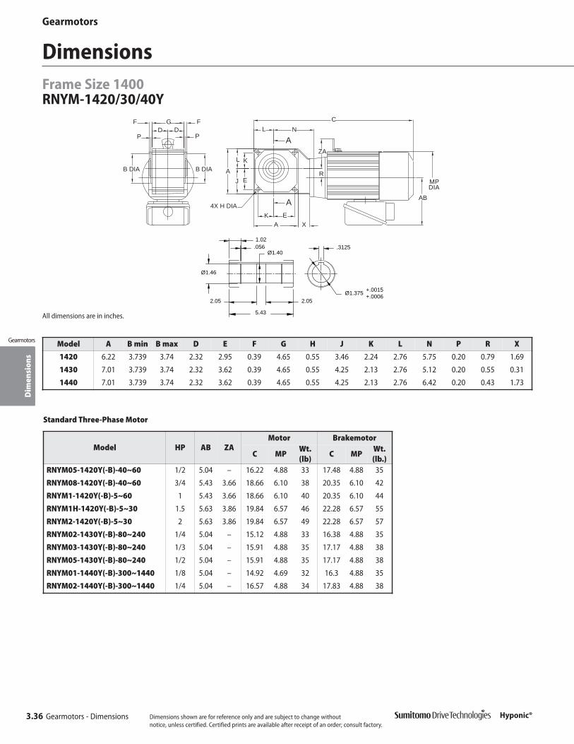
Dim
ensi
ons
Gearmotors
3.36 Gearmotors - Dimensions
Gearmotors
Hyponic®
DimensionsFrame Size 1400RNYM-1420/30/40Y
Dimensions shown are for reference only and are subject to change without notice, unless certified. Certified prints are available after receipt of an order; consult factory.
All dimensions are in inches.men
sion
s
FD D
B DIA B DIA
L N
A
L K
J E
4X H DIAK E
A X
ZA
R
AB
MPDIA
C
A
A
F G
P P
Ø1.40
5.43
1.02
Ø1.46
2.05
.056
2.05Ø1.375
.3125
+.0015+.0006
Model A B min B max D E F G H J K L N P R X
1420 6.22 3.739 3.74 2.32 2.95 0.39 4.65 0.55 3.46 2.24 2.76 5.75 0.20 0.79 1.69
1430 7.01 3.739 3.74 2.32 3.62 0.39 4.65 0.55 4.25 2.13 2.76 5.12 0.20 0.55 0.31
1440 7.01 3.739 3.74 2.32 3.62 0.39 4.65 0.55 4.25 2.13 2.76 6.42 0.20 0.43 1.73
Standard Three-Phase Motor
Model HP AB ZAMotor Brakemotor
C MPWt.(lb)
C MPWt.(lb.)
RNYM05-1420Y(-B)-40~60 1/2 5.04 – 16.22 4.88 33 17.48 4.88 35
RNYM08-1420Y(-B)-40~60 3/4 5.43 3.66 18.66 6.10 38 20.35 6.10 42
RNYM1-1420Y(-B)-5~60 1 5.43 3.66 18.66 6.10 40 20.35 6.10 44
RNYM1H-1420Y(-B)-5~30 1.5 5.63 3.86 19.84 6.57 46 22.28 6.57 55
RNYM2-1420Y(-B)-5~30 2 5.63 3.86 19.84 6.57 49 22.28 6.57 57
RNYM02-1430Y(-B)-80~240 1/4 5.04 – 15.12 4.88 33 16.38 4.88 35
RNYM03-1430Y(-B)-80~240 1/3 5.04 – 15.91 4.88 35 17.17 4.88 38
RNYM05-1430Y(-B)-80~240 1/2 5.04 – 15.91 4.88 35 17.17 4.88 38
RNYM01-1440Y(-B)-300~1440 1/8 5.04 – 14.92 4.69 32 16.3 4.88 35
RNYM02-1440Y(-B)-300~1440 1/4 5.04 – 16.57 4.88 34 17.83 4.88 38

Dim
ensi
ons
Gearmotors
Gearmotors - Dimensions 3.37
Gearmotors
Hyponic®
DimensionsFrame Size 1400
RNYM-1420/30/40Y (cont.)
Dimensions shown are for reference only and are subject to change without notice, unless certified. Certified prints are available after receipt of an order; consult factory.
All dimensions are in inches.
Model HP AB ZAMotor Brakemotor
C MPWt.(lb)
C MPWt.(lb)
RNYM05-1420Y-CB(-B)-40~60 1/2 5.04 3.66 18.66 6.10 40 20.35 6.10 44
RNYM02-1430Y-CB(-B)-80~240 1/4 4.65 – 15.91 4.88 35 17.17 4.88 38
RNYM01-1440Y-CB(-B)-300~1440 1/8 4.65 – 16.57 4.88 34 17.83 4.88 38
RNYM02-1440Y-CB(-B)-300~1440 1/4 4.65 – 17.36 4.88 38 18.62 4.88 40
Single-Phase Motor
AF-Motor
Model HP AB ZAMotor Brakemotor
C MPWt.(lb)
C MPWt.(lb)
RNYM05-1420Y-AV(-B)-40~60 1/2 5.43 3.66 18.66 6.10 40 20.35 6.10 44
RNYM08-1420Y-AV(-B)-5~30 3/4 5.63 3.86 19.84 6.57 46 22.28 6.57 55
RNYM1-1420Y-AV(-B)-5~30 1 5.63 3.86 19.84 6.57 49 22.28 6.57 57
RNYM02-1430Y-AV(-B)-80~240 1/4 5.04 – 15.91 4.88 35 17.17 4.88 38
RNYM03-1430Y-AV(-B)-80~240 1/2 5.04 – 15.91 4.88 35 17.17 4.88 38
RNYM01-1440Y-AV(-B)-300~1440 1/8 5.04 – 16.57 4.88 34 17.83 4.88 38
RNYM02-1440Y-AV(-B)-300~480 1/4 5.04 – 17.36 4.88 38 18.62 4.88 40
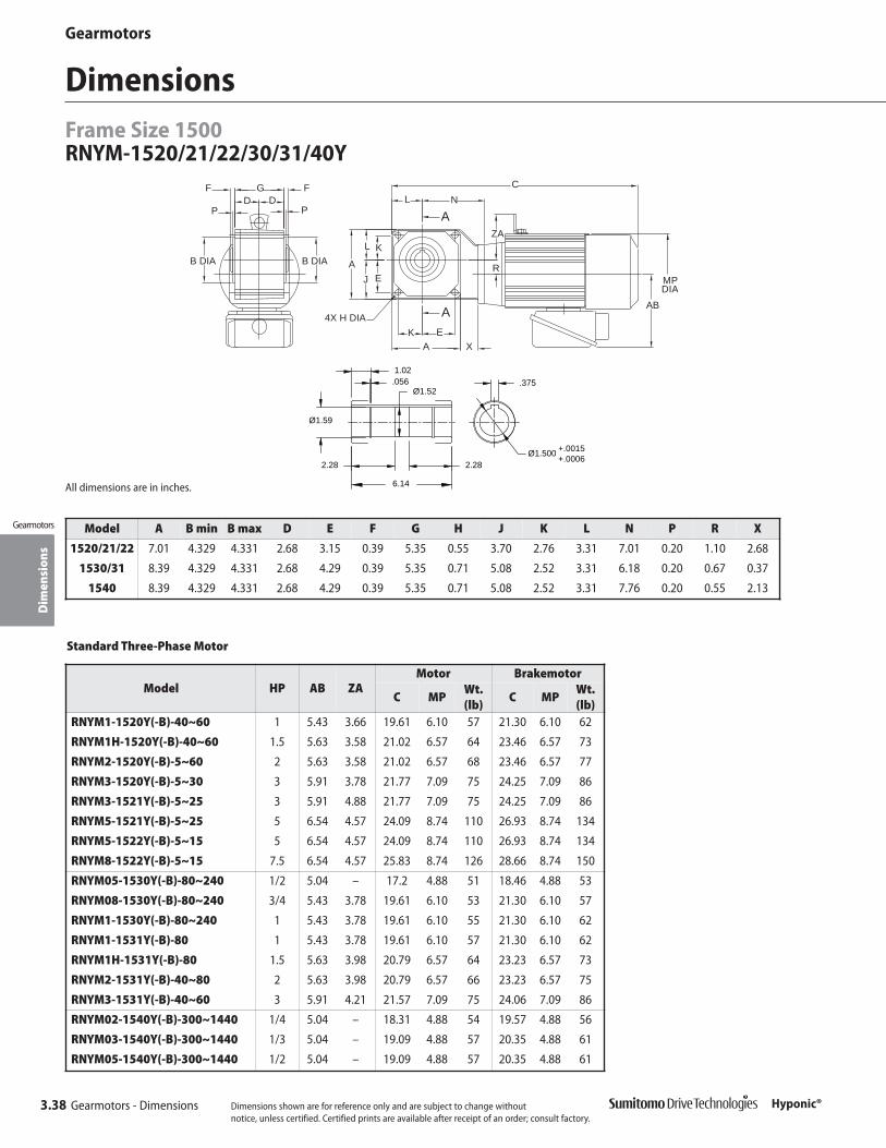
Dim
ensi
ons
Gearmotors
3.38 Gearmotors - Dimensions
Gearmotors
Hyponic®
DimensionsFrame Size 1500RNYM-1520/21/22/30/31/40Y
men
sion
s
FD D
B DIA B DIA
L N
A
L K
J E
4X H DIAK E
A X
ZA
R
AB
MPDIA
C
A
A
F G
P P
Dimensions shown are for reference only and are subject to change without notice, unless certified. Certified prints are available after receipt of an order; consult factory.
All dimensions are in inches.
Ø1.52
6.14
1.02
Ø1.59
2.28
.056
2.28Ø1.500
.375
+.0015+.0006
Model A B min B max D E F G H J K L N P R X
1520/21/22 7.01 4.329 4.331 2.68 3.15 0.39 5.35 0.55 3.70 2.76 3.31 7.01 0.20 1.10 2.68
1530/31 8.39 4.329 4.331 2.68 4.29 0.39 5.35 0.71 5.08 2.52 3.31 6.18 0.20 0.67 0.37
1540 8.39 4.329 4.331 2.68 4.29 0.39 5.35 0.71 5.08 2.52 3.31 7.76 0.20 0.55 2.13
Model HP AB ZAMotor Brakemotor
C MPWt.(lb)
C MPWt.(lb)
RNYM1-1520Y(-B)-40~60 1 5.43 3.66 19.61 6.10 57 21.30 6.10 62
RNYM1H-1520Y(-B)-40~60 1.5 5.63 3.58 21.02 6.57 64 23.46 6.57 73
RNYM2-1520Y(-B)-5~60 2 5.63 3.58 21.02 6.57 68 23.46 6.57 77
RNYM3-1520Y(-B)-5~30 3 5.91 3.78 21.77 7.09 75 24.25 7.09 86
RNYM3-1521Y(-B)-5~25 3 5.91 4.88 21.77 7.09 75 24.25 7.09 86
RNYM5-1521Y(-B)-5~25 5 6.54 4.57 24.09 8.74 110 26.93 8.74 134
RNYM5-1522Y(-B)-5~15 5 6.54 4.57 24.09 8.74 110 26.93 8.74 134
RNYM8-1522Y(-B)-5~15 7.5 6.54 4.57 25.83 8.74 126 28.66 8.74 150
RNYM05-1530Y(-B)-80~240 1/2 5.04 – 17.2 4.88 51 18.46 4.88 53
RNYM08-1530Y(-B)-80~240 3/4 5.43 3.78 19.61 6.10 53 21.30 6.10 57
RNYM1-1530Y(-B)-80~240 1 5.43 3.78 19.61 6.10 55 21.30 6.10 62
RNYM1-1531Y(-B)-80 1 5.43 3.78 19.61 6.10 57 21.30 6.10 62
RNYM1H-1531Y(-B)-80 1.5 5.63 3.98 20.79 6.57 64 23.23 6.57 73
RNYM2-1531Y(-B)-40~80 2 5.63 3.98 20.79 6.57 66 23.23 6.57 75
RNYM3-1531Y(-B)-40~60 3 5.91 4.21 21.57 7.09 75 24.06 7.09 86
RNYM02-1540Y(-B)-300~1440 1/4 5.04 – 18.31 4.88 54 19.57 4.88 56
RNYM03-1540Y(-B)-300~1440 1/3 5.04 – 19.09 4.88 57 20.35 4.88 61
RNYM05-1540Y(-B)-300~1440 1/2 5.04 – 19.09 4.88 57 20.35 4.88 61
Standard Three-Phase Motor

Dim
ensi
ons
Gearmotors
Gearmotors - Dimensions 3.39
Gearmotors
Hyponic®
DimensionsFrame Size 1500
RNYM-1520/21/22/30/31/40Y (cont.)
Dimensions shown are for reference only and are subject to change without notice, unless certified. Certified prints are available after receipt of an order; consult factory.
All dimensions are in inches.
ModelMotor
HPAB ZA
Motor Brakemotor
C MPWt. (lb)
C MPWt.(lb)
RNYM05-1530Y-CB(-B)-80~240 1/2 5.04 3.780 19.61 6.10 55 21.3 6.1 62
RNYM01-1540Y-CB(-B)-600~1440 1/8 4.65 – 18.31 4.88 55 19.57 4.88 60
RNYM02-1540Y-CB(-B)-300~1440 1/4 4.65 – 19.09 4.88 57 20.35 4.88 61
Single-Phase Motor
AF-Motor
Model HP AB ZAMotor Brakemotor
C MPWt.(lb)
C MPWt.(lb)
RNYM08-1520Y-AV(-B)-40~60 3/4 5.63 3.583 21.02 6.57 64 23.46 6.57 73
RNYM1-1520Y-AV(-B)-40~60 1 5.63 3.583 21.02 6.57 68 23.46 6.57 77
RNYM1H-1520Y-AV(-B)-5~30 1.5 5.91 3.780 21.77 7.09 75 24.25 7.09 86
RNYM2-1520Y-AV(-B)-5~30 2 5.91 3.780 21.77 7.09 75 24.25 7.09 86
RNYM3-1521Y-AV(-B)-5~25 3 6.5 4.567 24.09 8.74 110 26.93 8.74 134
RNYM5-1522Y-AV(-B)-5~15 5 6.5 4.567 25.83 8.74 126 28.66 8.74 150
RNYM05-1530Y-AV(-B)-80~240 1/2 5.43 3.780 19.61 6.10 55 21.3 6.10 62
RNYM08-1531Y-AV(-B)-80 3/4 5.63 3.976 20.79 6.57 64 23.23 6.57 73
RNYM1-1531Y-AV(-B)-80 1 5.63 3.976 20.79 6.57 66 23.23 6.57 75
RNYM1H-1531Y-AV(-B)-40~60 1.5 5.91 4.213 21.57 7.09 75 24.06 7.09 86
RNYM2-1531Y-AV(-B)-40~60 2 5.91 4.213 21.57 7.09 75 24.06 7.09 86
RNYM01-1540Y-AV(-B)-600~1440 1/8 5.04 – 18.31 4.88 54 19.57 4.88 57
RNYM02-1540Y-AV(-B)-300~1440 1/4 5.04 – 19.09 4.88 57 20.35 4.88 61
RNYM03-1540Y-AV(-B)-300~480 1/2 5.04 – 19.09 4.88 57 20.35 4.88 62
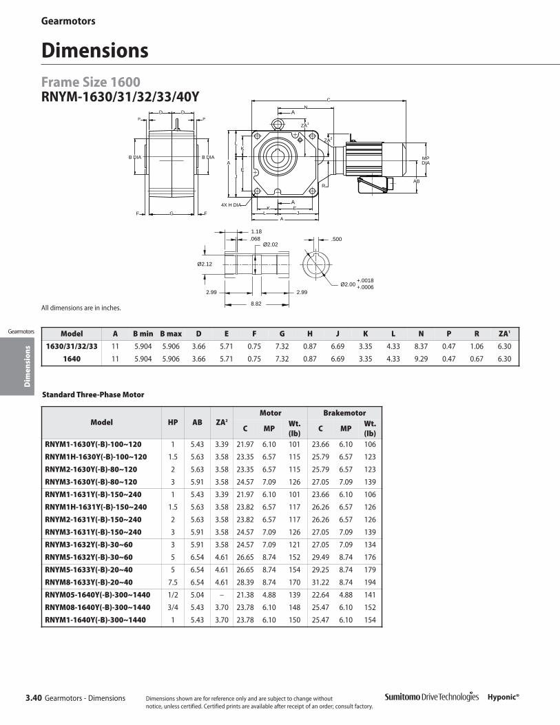
Dim
ensi
ons
Gearmotors
3.40 Gearmotors - Dimensions
DimensionsFrame Size 1600RNYM-1630/31/32/33/40Y
Gearmotors
Hyponic®
CN
A
EFGF
P
B DIA
P
D D
K
A
L
EJ
K
ABR
MPDIA
JL
B DIA
ZA2
ZA1
4X H DIA
A
A
All dimensions are in inches.
Ø2.02
8.82
1.18
Ø2.12
2.99
.068
2.99Ø2.00
.500
+.0018+.0006
Model A B min B max D E F G H J K L N P R ZA1
1630/31/32/33 11 5.904 5.906 3.66 5.71 0.75 7.32 0.87 6.69 3.35 4.33 8.37 0.47 1.06 6.30
1640 11 5.904 5.906 3.66 5.71 0.75 7.32 0.87 6.69 3.35 4.33 9.29 0.47 0.67 6.30
Standard Three-Phase Motor
Model HP AB ZA2
Motor Brakemotor
C MPWt. (lb)
C MPWt.(lb)
RNYM1-1630Y(-B)-100~120 1 5.43 3.39 21.97 6.10 101 23.66 6.10 106
RNYM1H-1630Y(-B)-100~120 1.5 5.63 3.58 23.35 6.57 115 25.79 6.57 123
RNYM2-1630Y(-B)-80~120 2 5.63 3.58 23.35 6.57 115 25.79 6.57 123
RNYM3-1630Y(-B)-80~120 3 5.91 3.58 24.57 7.09 126 27.05 7.09 139
RNYM1-1631Y(-B)-150~240 1 5.43 3.39 21.97 6.10 101 23.66 6.10 106
RNYM1H-1631Y(-B)-150~240 1.5 5.63 3.58 23.82 6.57 117 26.26 6.57 126
RNYM2-1631Y(-B)-150~240 2 5.63 3.58 23.82 6.57 117 26.26 6.57 126
RNYM3-1631Y(-B)-150~240 3 5.91 3.58 24.57 7.09 126 27.05 7.09 139
RNYM3-1632Y(-B)-30~60 3 5.91 3.58 24.57 7.09 121 27.05 7.09 134
RNYM5-1632Y(-B)-30~60 5 6.54 4.61 26.65 8.74 152 29.49 8.74 176
RNYM5-1633Y(-B)-20~40 5 6.54 4.61 26.65 8.74 154 29.25 8.74 179
RNYM8-1633Y(-B)-20~40 7.5 6.54 4.61 28.39 8.74 170 31.22 8.74 194
RNYM05-1640Y(-B)-300~1440 1/2 5.04 – 21.38 4.88 139 22.64 4.88 141
RNYM08-1640Y(-B)-300~1440 3/4 5.43 3.70 23.78 6.10 148 25.47 6.10 152
RNYM1-1640Y(-B)-300~1440 1 5.43 3.70 23.78 6.10 150 25.47 6.10 154
Dimensions shown are for reference only and are subject to change without notice, unless certified. Certified prints are available after receipt of an order; consult factory.

Dim
ensi
ons
Gearmotors
Gearmotors - Dimensions 3.41
Gearmotors
Hyponic®
DimensionsFrame Size 1600
RNYM-1630/31/32/33/40Y (cont.)
All dimensions are in inches.
Single-Phase Motor
Model HP AB ZA2
Motor Brakemotor
C MPWt.(lb)
C MPWt.(lb)
RNYM02-1640Y-CB(-B)-300~1440 1/4 4.65 – 21.38 4.88 139 22.64 4.88 141
RNYM05-1640Y-CB(-B)-300~1440 1/2 5.04 3.78 23.78 6.10 139 25.47 6.10 143
AF-Motor
Model HP AB ZAMotor Brakemotor
C MPWt.(lb)
C MPWt.(lb)
RNYM08-1630Y-AV(-B)-100~120 3/4 5.63 3.58 23.35 6.57 115 25.79 6.57 123
RNYM1-1630Y-AV(-B)-100~120 1 5.63 3.58 23.35 6.57 115 25.79 6.57 123
RNYM1H-1630Y-AV(-B)-100~120 1.5 5.91 3.82 24.57 7.09 126 27.05 7.09 139
RNYM2-1630Y-AV(-B)-100~120 2 5.91 3.82 24.57 7.09 126 27.05 7.09 139
RNYM08-1631Y-AV(-B)-150~240 3/4 5.63 3.58 23.82 6.57 117 26.26 6.57 126
RNYM1-1631Y-AV(-B)-150~240 1 5.63 3.58 23.82 6.57 117 26.26 6.57 126
RNYM1H-1631Y-AV(-B)-150~240 1.5 5.91 3.82 24.57 7.09 126 27.05 7.09 139
RNYM2-1631Y-AV(-B)-150~240 2 5.91 3.82 24.57 7.09 126 27.05 7.09 139
RNYM3-1632Y-AV(-B)-30~60 3 6.5 4.61 26.65 8.74 152 29.49 8.74 176
RNYM5-1633Y-AV(-B)-20~40 5 6.5 4.61 28.39 8.74 170 31.22 8.74 194
RNYM02-1640Y-AV(-B)-600~1440 1/4 5.04 – 21.38 4.88 139 22.64 4.88 141
RNYM03-1640Y-AV(-B)-600~1440 1/2 5.04 – 21.38 4.88 139 22.64 4.88 141
RNYM05-1640Y-AV(-B)-300~1440 1/2 5.43 3.78 23.78 6.10 139 25.47 6.10 143
Dimensions shown are for reference only and are subject to change without notice, unless certified. Certified prints are available after receipt of an order; consult factory.

Gearmotors
3.42 Gearmotors Hyponic®
This page intentionally left blank.
Opt
ions
Hyponic®
Options
Options 4.1Hyponic®
Options4

Plug-in Solid Output ShaftFrame Size 1100 ~ 1300
4.2 Options
OptionsO
ptio
ns
Hyponic®
Hyponic®
ZA
B DIAU DIAB DIA MDDIA
MW
AB
A
4X H DIA
MPDIA
R
J E
A
EJL
K
C
N
L K
V
PPVP
DS
DD
W
KEY
S
Dimensions shown are for reference only and are subject to change without notice, unless certified.Certified prints are available after receipt of an order; consult factory.
All dimensions are in inches.
B DIA
AB
B DIA U DIA
DS
W
PVP MW
PD
MDDIA
DV
KEY
S
B DIA
W
U DIAB DIA U DIA
VP
DS
V
DS
D V
W
DP P
VP
AB
KEY
S
KEY
S
L
R T
Model A B min B max D DS E H J K L N P R MD MW
1120L/R/TY-X1 3.54 2.046 2.047 1.30 3.27 1.65 0.26 1.97 1.26 1.57 3.23 0.24 0.79 2.20 0.79
1220L/R/TY-X1 4.53 3.070 3.071 1.46 3.96 2.24 0.35 2.60 1.57 1.93 3.78 0.20 1.10 2.32 1.26
1230L/R/TY-X1 5.00 3.070 3.071 1.61 4.11 2.56 0.35 2.99 1.57 2.01 3.74 0.20 0.51 2.32 1.26
1320L/R/TY-X1 5.20 3.345 3.346 1.81 4.61 2.44 0.43 2.91 1.81 2.28 4.69 0.20 1.08 2.64 1.26
1330L/R/TY-X1 5.98 3.345 3.346 1.81 4.61 3.11 0.43 3.62 1.85 2.36 4.25 0.20 0.43 2.64 1.26
1340L/R/TY-X1 5.98 3.345 3.346 1.81 4.61 3.11 0.43 3.62 1.85 2.36 5.16 0.20 0.35 2.64 1.26
ModelOutput Shaft
U min U max W V VP S Key
1120L/R/TY-X1 0.749 0.750 1.97 1.10 0.87 10-32 UNF x 0.630 3/16 x 3/16
1220L/R/TY-X1 0.999 1.000 2.50 1.42 1.08 5/16-18 UNC x 0.630 1/4 x 1/4
1230L/R/TY-X1 0.999 1.000 2.50 1.42 1.08 5/16-18 UNC x 0.630 1/4 x 1/4
1320L/R/TY-X1 1.249 1.250 2.80 1.65 1.14 5/16-18 UNC x 0.630 1/4 x 1/4
1330L/R/TY-X1 1.249 1.250 2.80 1.65 1.14 5/16-18 UNC x 0.630 1/4 x 1/4
1340L/R/TY-X1 1.249 1.250 2.80 1.65 1.14 5/16-18 UNC x 0.630 1/4 x 1/4
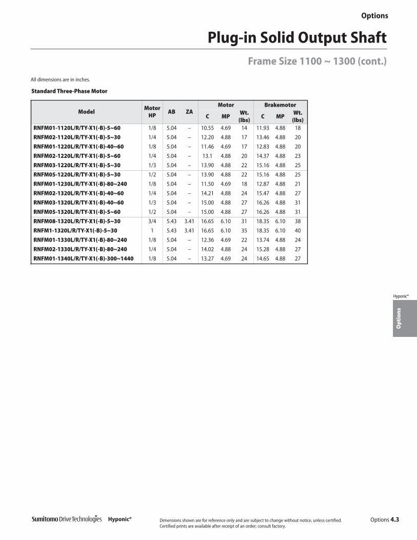
Opt
ions
Options 4.3
Options
Hyponic®
Hyponic®
Plug-in Solid Output ShaftFrame Size 1100 ~ 1300 (cont.)
Dimensions shown are for reference only and are subject to change without notice, unless certified.Certified prints are available after receipt of an order; consult factory.
All dimensions are in inches.
Standard Three-Phase Motor
ModelMotor
HPAB ZA
Motor Brakemotor
C MPWt.
(lbs)C MP
Wt.(lbs)
RNFM01-1120L/R/TY-X1(-B)-5~60 1/8 5.04 – 10.55 4.69 14 11.93 4.88 18
RNFM02-1120L/R/TY-X1(-B)-5~30 1/4 5.04 – 12.20 4.88 17 13.46 4.88 20
RNFM01-1220L/R/TY-X1(-B)-40~60 1/8 5.04 – 11.46 4.69 17 12.83 4.88 20
RNFM02-1220L/R/TY-X1(-B)-5~60 1/4 5.04 – 13.1 4.88 20 14.37 4.88 23
RNFM03-1220L/R/TY-X1(-B)-5~30 1/3 5.04 – 13.90 4.88 22 15.16 4.88 25
RNFM05-1220L/R/TY-X1(-B)-5~30 1/2 5.04 – 13.90 4.88 22 15.16 4.88 25
RNFM01-1230L/R/TY-X1(-B)-80~240 1/8 5.04 – 11.50 4.69 18 12.87 4.88 21
RNFM02-1320L/R/TY-X1(-B)-40~60 1/4 5.04 – 14.21 4.88 24 15.47 4.88 27
RNFM03-1320L/R/TY-X1(-B)-40~60 1/3 5.04 – 15.00 4.88 27 16.26 4.88 31
RNFM05-1320L/R/TY-X1(-B)-5~60 1/2 5.04 – 15.00 4.88 27 16.26 4.88 31
RNFM08-1320L/R/TY-X1(-B)-5~30 3/4 5.43 3.41 16.65 6.10 31 18.35 6.10 38
RNFM1-1320L/R/TY-X1(-B)-5~30 1 5.43 3.41 16.65 6.10 35 18.35 6.10 40
RNFM01-1330L/R/TY-X1(-B)-80~240 1/8 5.04 – 12.36 4.69 22 13.74 4.88 24
RNFM02-1330L/R/TY-X1(-B)-80~240 1/4 5.04 – 14.02 4.88 24 15.28 4.88 27
RNFM01-1340L/R/TY-X1(-B)-300~1440 1/8 5.04 – 13.27 4.69 24 14.65 4.88 27
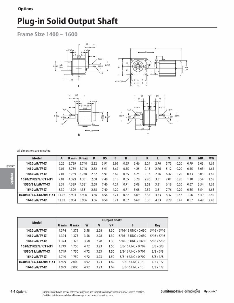
4.4 Options
OptionsO
ptio
ns
Hyponic®
Hyponic® Dimensions shown are for reference only and are subject to change without notice, unless certified.Certified prints are available after receipt of an order; consult factory.
Model A B min B max D DS E H J K L N P R MD MW
1420L/R/TY-X1 6.22 3.739 3.740 2.32 5.91 2.95 0.55 3.46 2.24 2.76 5.75 0.20 0.79 3.03 1.65
1430L/R/TY-X1 7.01 3.739 3.740 2.32 5.91 3.62 0.55 4.25 2.13 2.76 5.12 0.20 0.55 3.03 1.65
1440L/R/TY-X1 7.01 3.739 3.740 2.32 5.91 3.62 0.55 4.25 2.13 2.76 6.42 0.20 0.43 3.03 1.65
1520/21/22/L/R/TY-X1 7.01 4.329 4.331 2.68 7.40 3.15 0.55 3.70 2.76 3.31 7.01 0.20 1.10 3.54 1.65
1530/31/L/R/TY-X1 8.39 4.329 4.331 2.68 7.40 4.29 0.71 5.08 2.52 3.31 6.18 0.20 0.67 3.54 1.65
1540L/R/TY-X1 8.39 4.329 4.331 2.68 7.40 4.29 0.71 5.08 2.52 3.31 7.76 0.20 0.55 3.54 1.65
1630/31/32/33/L/R/TY-X1 11.02 5.904 5.906 3.66 8.58 5.71 0.87 6.69 3.35 4.33 8.37 0.47 1.06 4.49 2.40
1640L/R/TY-X1 11.02 5.904 5.906 3.66 8.58 5.71 0.87 6.69 3.35 4.33 9.29 0.47 0.67 4.49 2.40
ModelOutput Shaft
U min U max W V VP S Key
1420L/R/TY-X1 1.374 1.375 3.58 2.28 1.30 5/16-18 UNC x 0.630 5/16 x 5/16
1430L/R/TY-X1 1.374 1.375 3.58 2.28 1.30 5/16-18 UNC x 0.630 5/16 x 5/16
1440L/R/TY-X1 1.374 1.375 3.58 2.28 1.30 5/16-18 UNC x 0.630 5/16 x 5/16
1520/21/22/L/R/TY-X1 1.749 1.750 4.72 3.23 1.50 3/8-16 UNC x 0.709 3/8 x 3/8
1530/31/L/R/TY-X1 1.749 1.750 4.72 3.23 1.50 3/8-16 UNC x 0.709 3/8 x 3/8
1540L/R/TY-X1 1.749 1.750 4.72 3.23 1.50 3/8-16 UNC x 0.709 3/8 x 3/8
1630/31/32/33/L/R/TY-X1 1.999 2.000 4.92 3.23 1.69 3/8-16 UNC x 18 1/2 x 1/2
1640L/R/TY-X1 1.999 2.000 4.92 3.23 1.69 3/8-16 UNC x 18 1/2 x 1/2
Plug-in Solid Output ShaftFrame Size 1400 ~ 1600
ZA
B DIAU DIAB DIA MDDIA
MW
AB
A
4X H DIA
MPDIA
R
J E
A
EJL
K
C
N
L K
V
PPVP
DS
DD
W
KEY
S
All dimensions are in inches.
B DIA
AB
B DIA U DIA
DS
W
PVP MW
PD
MDDIA
DV
KEY
S
B DIA
W
U DIAB DIA U DIA
VP
DS
V
DS
D V
W
DP P
VP
AB
KEY
S
KEY
S
L
R T

Opt
ions
Options 4.5
Options
Hyponic®
Hyponic®
All dimensions are in inches.
Standard Three-Phase Motor
ModelMotor
HPAB ZA
Motor Brakemotor
C MPWt.
(lbs)C MP
Wt.(lbs)
RNFM05-1420L/R/TY-X1(-B)-40~60 1/2 5.04 – 16.22 4.88 36 17.48 4.88 39
RNFM08-1420L/R/TY-X1(-B)-40~60 3/4 5.43 3.66 18.66 6.10 41 20.35 6.10 45
RNFM1-1420L/R/TY-X1(-B)-5~60 1 5.43 3.66 18.6 6.10 43 20.35 6.10 47
RNFM1H-1420L/R/TY-X1(-B)-5~30 1.5 5.63 3.86 19.84 6.57 50 22.28 6.57 58
RNFM2-1420L/R/TY-X1(-B)-5~30 2 5.63 3.86 19.84 6.57 51.8 22.28 6.57 60.6
RNFM02-1430L/R/TY-X1(-B)-80~240 1/4 5.04 – 15.12 4.88 36.4 16.38 4.88 38.6
RNFM03-1430L/R/TY-X1(-B)-80~240 1/3 5.04 – 15.91 4.88 38.6 17.17 4.88 40.8
RNFM05-1430L/R/TY-X1(-B)-80~240 1/2 5.04 – 15.91 4.88 38.6 17.17 4.88 40.8
RNFM01-1440L/R/TY-X1(-B)-300~1440 1/8 5.04 – 14.92 4.69 35.3 16.30 4.88 38.6
RNFM02-1440L/R/TY-X1(-B)-300~1440 1/4 5.04 – 16.57 4.88 37.5 17.83 4.88 40.8
RNFM1-1520L/R/TY-X1(-B)-40~60 1 5.43 3.66 19.61 6.10 62.8 21.30 6.10 67.2
RNFM1H-1520L/R/TY-X1(-B)-40~60 1.5 5.63 3.58 21.02 6.57 69.4 23.46 6.57 78.3
RNFM2-1520L/R/TY-X1(-B)-5~60 2 5.63 3.58 21.02 6.57 73.9 23.46 6.57 82.7
RNFM3-1520L/R/TY-X1(-B)-5~30 3 5.91 3.78 21.77 7.09 80.5 24.25 7.09 91.5
RNFM3-1521L/R/T/Y-X1(-B)-5~25 3 5.91 4.88 21.77 7.09 80.5 24.25 7.09 91.5
RNFM5-1521L/R/TY-X1(-B)-5~25 5 6.54 4.57 24.09 8.74 116 26.93 8.74 140
RNFM5-1522L/R/TY-X1(-B)-5~15 5 6.54 4.57 24.09 8.74 116 26.93 8.74 140
RNFM8-1522L/R/TY-X1(-B)-5~15 7.5 6.54 4.57 25.83 8.74 131 28.66 8.74 155
RNFM05-1530L/R/TY-X1(-B)-80~240 1/2 5.04 – 17.20 4.88 56.2 18.46 4.88 58.4
RNFM08-1530L/R/TY-X1(-B)-80~240 3/4 5.43 3.78 19.61 6.10 58.4 21.30 6.10 62.8
RNFM1-1530L/R/TY-X1(-B)-80~240 1 5.43 3.78 19.61 6.10 60.6 21.30 6.10 67.2
RNFM1-1531L/R/TY-X1(-B)-80 1 5.43 3.78 19.61 6.10 62.8 21.30 6.10 67.2
RNFM1H-1531L/R/TY-X1(-B)-80 1.5 5.63 3.98 20.79 6.57 69.4 23.23 6.57 78.3
RNFM2-1531L/R/TY-X1(-B)-40~80 2 5.63 3.98 20.79 6.57 71.6 23.23 6.57 80.5
RNFM3-1531L/R/T/Y-X1(-B)-40~60 3 5.91 4.21 21.57 7.09 80.5 24.06 7.09 91.5
RNFM02-1540L/R/TY-X1(-B)-300~1440 1/4 5.04 – 18.31 4.88 59.5 19.57 4.88 61.7
RNFM03-1540L/R/TY-X1(-B)-300~1440 1/3 5.04 – 19.09 4.88 62.8 20.35 4.88 66.1
RNFM05-1540L/R/TY-X1(-B)-300~1440 1/2 5.04 – 19.09 4.88 62.8 20.35 4.88 66.1
RNFM1-1630L/R/TY-X1(-B)-100~120 1 5.43 3.39 21.97 6.10 111 23.66 6.10 116
RNFM1H-1630L/R/TY-X1(-B)-100~120 1.5 5.63 3.58 23.35 6.57 125 25.79 6.57 133
RNFM2-1630L/R/TY-X1(-B)-80~120 2 5.63 3.58 23.35 6.57 125 25.79 6.57 133
RNFM3-1630L/R/TY-X1(-B)-80~120 3 5.91 3.58 24.57 7.09 136 27.05 7.09 149
RNFM1-1631L/R/TY-X1(-B)-150~240 1 5.43 3.39 21.97 6.10 111 23.66 6.10 116
RNFM1H-1631L/R/TY-X1(-B)-150~240 1.5 5.63 3.58 23.82 6.57 127 26.26 6.57 136
RNFM2-1631L/R/TY-X1(-B)-150~240 2 5.63 3.58 23.82 6.57 127 26.26 6.57 136
RNFM3-1631L/R/TY-X1(-B)-150~240 3 5.91 3.58 24.57 7.09 136 27.05 7.09 149
RNFM3-1632L/R/TY-X1(-B)-30~60 3 5.91 3.58 24.57 7.09 131 27.05 7.09 144
RNFM5-1632L/R/TY-X1(-B)-30~60 5 6.54 4.61 26.65 8.74 162 29.49 8.74 186
RNFM5-1633L/R/TY-X1(-B)-20~40 5 6.54 4.61 26.65 8.74 164 29.25 8.74 188
RNFM8-1633L/R/TY-X1(-B)-20~40 7.5 6.54 4.61 28.39 8.74 180 31.22 8.74 204
RNFM05-1640L/R/TY-X1(-B)-300~1440 1/2 5.04 – 21.38 4.88 149 22.64 4.88 151
RNFM08-1640L/R/TY-X1(-B)-300~1440 3/4 5.43 3.70 23.78 6.10 158 25.47 6.10 162
RNFM1-1640L/R/TY-X1(-B)-300~1440 1 5.43 3.70 23.78 6.10 160 25.47 6.10 164
Plug-in Solid Output ShaftFrame Size 1400 ~ 1600 (cont.)
Dimensions shown are for reference only and are subject to change without notice, unless certified.Certified prints are available after receipt of an order; consult factory.

4.6 Options
OptionsO
ptio
ns
Hyponic®
Hyponic®
Plug-in Shaft with Bolt-on FeetFrame Size 1100 ~ 1500
ZA
MDDIA
U DIAMPDIA
C
R
AEAJ
EJKJGG
JJ
AE
LJ
NLJ
G
GJGE
GG
GE
WJ
DS
MW VDD
DC
AB
S
KEY
4X HJ DIA
All dimensions are in inches.
DIA MDDIA
GJ GEGE
WJ
DS
DC
V
G
AB
G
MWD D
Y
U DIA
AB
WJ
GEGJGE
G GG
DSDS
WJ
U DIA
DDVV
S
KEY
S
KEY
L
R T
Model AJ AE D DS DC G GJ GE JJ LJ GG KJ EJ HJ N R MD MW
1120L/R/TY-J1 2.76 0.39 1.30 3.27 2.09 2.52 4.72 0.39 3.54 1.57 0.39 1.26 1.50 0.35 3.23 0.79 2.20 0.79
1220L/R/TY-J1 4.13 0.43 1.46 3.96 2.72 2.83 5.35 0.59 4.33 2.01 0.39 1.57 2.56 0.35 3.78 1.10 2.32 1.26
1230L/R/TY-J1 4.13 0.43 1.61 4.11 2.87 3.15 5.67 0.59 4.33 2.01 0.39 1.57 2.56 0.35 3.74 0.51 2.32 1.26
1320L/R/TY-J1 4.96 0.51 1.81 4.61 3.07 3.54 6.46 0.59 4.41 2.36 0.47 1.85 3.11 0.43 4.69 1.08 2.64 1.26
1330L/R/TY-J1 4.96 0.51 1.81 4.61 3.07 3.54 6.46 0.59 4.41 2.36 0.47 1.85 3.11 0.43 4.25 0.43 2.64 1.26
1340L/R/TY-J1 4.96 0.51 1.81 4.61 3.07 3.54 6.46 0.59 4.41 2.36 0.47 1.85 3.11 0.43 5.16 0.35 2.64 1.26
1420L/R/TY-J1 5.51 0.75 2.32 5.91 3.98 4.57 8.03 0.79 5.20 2.76 0.47 2.01 3.50 0.55 5.75 0.79 3.03 1.65
1430L/R/TY-J1 5.51 0.75 2.32 5.91 3.98 4.57 8.03 0.79 5.20 2.76 0.47 2.01 3.50 0.55 5.12 0.55 3.03 1.65
1440L/R/TY-J1 5.51 0.75 2.32 5.91 3.98 4.57 8.03 0.79 5.20 2.76 0.47 2.01 3.50 0.55 6.42 0.43 3.03 1.65
1520L/R/TY-J1 6.81 0.79 2.68 7.40 4.33 5.28 9.61 0.79 6.30 3.31 0.59 2.52 4.29 0.71 7.01 1.10 3.54 1.65
1530/31/L/R/TY-J1 6.81 0.79 2.68 7.40 4.33 5.28 9.61 0.79 6.30 3.31 0.59 2.52 4.29 0.71 6.18 0.67 3.54 1.65
1540L/R/TY-J1 6.81 0.79 2.68 7.40 4.33 5.28 9.61 0.79 6.30 3.31 0.59 2.52 4.29 0.71 7.76 0.55 3.54 1.65
ModelOutput Shaft
U min U max WJ V S Key
1120L/R/TY-J1 0.749 0.750 0.91 1.10 10-32 UNF x 0.630 3/16 x 3/16
1220L/R/TY-J1 0.999 1.000 1.28 1.42 5/16-18 UNC x 0.630 1/4 x 1/4
1230L/R/TY-J1 0.999 1.000 1.28 1.42 5/16-18 UNC x 0.630 1/4 x 1/4
1320L/R/TY-J1 1.249 1.250 1.38 1.65 5/16-18 UNC x 0.630 1/4 x 1/4
1330L/R/TY-J1 1.249 1.250 1.38 1.65 5/16-18 UNC x 0.630 1/4 x 1/4
1340L/R/TY-J1 1.249 1.250 1.38 1.65 5/16-18 UNC x 0.630 1/4 x 1/4
1420L/R/TY-J1 1.374 1.375 1.89 2.28 5/16-18 UNC x 0.630 5/16 x 5/16
1430L/R/TY-J1 1.374 1.375 1.89 2.28 5/16-18 UNC x 0.630 5/16 x 5/16
1440L/R/TY-J1 1.374 1.375 1.89 2.28 5/16-18 UNC x 0.630 5/16 x 5/16
1520L/R/TY-J1 1.749 1.750 2.60 3.23 3/8-16 UNC x 0.709 3/8 x 3/8
1530/31/L/R/TY-J1 1.749 1.750 2.60 3.23 3/8-16 UNC x 0.709 3/8 x 3/8
1540L/R/TY-J1 1.749 1.750 2.60 3.23 3/8-16 UNC x 0.709 3/8 x 3/8
Dimensions shown are for reference only and are subject to change without notice, unless certified.Certified prints are available after receipt of an order; consult factory.

Opt
ions
Options 4.7
Options
Hyponic®
Hyponic®
Plug-in Shaft with Bolt-on FeetFrame Size 1100 ~ 1500 (cont.)
All dimensions are in inches.
Standard Three-Phase Motor
ModelMotor
HPAB ZA
Motor Brakemotor
C MP Wt C MP Wt
RNHM01-1120L/R/TY-J1(-B)-5~60 1/8 5.04 – 10.55 4.69 17 11.93 4.88 20
RNHM02-1120L/R/TY-J1(-B)-5~30 1/4 5.04 – 12.20 4.88 19 13.46 4.88 22
RNHM01-1220L/R/TY-J1(-B)-40~60 1/8 5.04 – 11.54 4.69 21 12.91 4.88 24
RNHM02-1220L/R/TY-J1(-B)-5~60 1/4 5.04 – 13.19 4.88 24 14.45 4.88 28
RNHM03-1220L/R/TY-J1(-B)-5~30 1/3 5.04 – 13.98 4.88 26 15.24 4.88 30
RNHM05-1220L/R/TY-J1(-B)-5~30 1/2 5.04 – 13.98 4.88 26 15.24 4.88 30
RNHM01-1230L/R/TY-J1(-B)-80~240 1/8 5.04 – 11.50 4.69 23 12.87 4.88 26
RNHM02-1320L/R/TY-J1(-B)-40~60 1/4 5.04 – 14.29 4.88 32 15.55 4.88 34
RNHM03-1320L/R/TY-J1(-B)-40~60 1/3 5.04 – 15.08 4.88 34 16.34 4.88 39
RNHM05-1320L/R/TY-J1(-B)-5~60 1/2 5.04 – 15.08 4.88 34 16.34 4.88 39
RNHM08-1320L/R/TY-J1(-B)-5~30 3/4 5.43 3.41 16.73 6.10 39 18.43 6.10 45
RNHM1-1320L/R/TY-J1(-B)-5~30 1 5.43 3.41 16.73 6.10 43 18.43 6.10 47
RNHM01-1330L/R/TY-J1(-B)-80~240 1/8 5.04 – 12.36 4.69 30 6.61 4.88 32
RNHM02-1330L/R/TY-J1(-B)-80~240 1/4 5.04 – 14.02 4.88 32 15.28 4.88 34
RNHM01-1340L/R/TY-J1(-B)-300~1440 1/8 5.04 – 13.27 4.69 32 14.65 4.88 34
RNHM05-1420L/R/TY-J1(-B)-40~60 1/2 5.04 – 16.22 4.88 47 6.85 4.88 50
RNHM08-1420L/R/TY-J1(-B)-40~60 3/4 5.43 3.66 18.66 6.10 52 20.35 6.10 56
RNHM1-1420L/R/TY-J1(-B)-5~60 1 5.43 3.66 18.66 6.10 54 20.35 6.10 58
RNHM1H-1420L/R/TY-J1(-B)-5~30 1.5 5.63 3.86 19.84 6.57 61 22.28 6.57 69
RNHM2-1420L/R/TY-J1(-B)-5~30 2 5.63 3.86 19.84 6.57 63 22.28 6.57 72
RNHM02-1430L/R/TY-J1(-B)-80~240 1/4 5.04 – 15.12 4.88 47 6.89 4.88 50
RNHM03-1430L/R/TY-J1(-B)-80~240 1/3 5.04 – 15.91 4.88 50 17.17 4.88 52
RNHM05-1430L/R/TY-J1(-B)-80~240 1/2 5.04 – 15.91 4.88 50 17.17 4.88 52
RNHM01-1440L/R/TY-J1(-B)-300~1440 1/8 5.04 – 14.92 4.69 46 16.30 4.88 50
RNHM02-1440L/R/TY-J1(-B)-300~1440 1/4 5.04 – 16.57 4.88 49 17.83 4.88 52
RNHM1-1520L/R/TY-J1(-B)-40~60 1 5.43 3.66 19.61 6.10 83 7.68 6.10 87
RNHM1H-1520L/R/TY-J1(-B)-40~60 1.5 5.63 3.58 21.02 6.57 89 23.46 6.57 98
RNHM2-1520L/R/TY-J1(-B)-5~60 2 5.63 3.58 21.02 6.57 94 23.46 6.57 103
RNHM3-1520L/R/TY-J1(-B)-5~30 3 5.91 3.78 21.77 7.09 100 24.25 7.09 111
RNHM05-1530L/R/TY-J1(-B)-80~240 1/2 5.04 – 17.20 4.88 76 18.46 4.88 78
RNHM08-1530L/R/TY-J1(-B)-80~240 3/4 5.43 3.78 19.61 6.10 78 21.30 6.10 83
RNHM1-1530L/R/TY-J1(-B)-80~240 1 5.43 3.78 19.61 6.10 80 21.30 6.10 87
RNHM1-1531L/R/TY-J1(-B)-80 1 5.43 3.78 19.61 6.10 83 21.30 6.10 87
RNHM1H-1531L/R/TY-J1(-B)-80 1.5 5.63 3.98 20.79 6.57 89 23.23 6.57 98
RNHM2-1531L/R/TY-J1(-B)-40~80 2 5.63 3.98 20.79 6.57 91 23.23 6.57 100
RNHM3-1531L/R/TY-J1(-B)-40~60 3 5.91 4.21 21.57 7.09 100 24.06 7.09 111
RNHM02-1540L/R/TY-J1(-B)-300~1440 1/4 5.04 – 18.31 4.88 79 19.57 4.88 82
RNHM03-1540L/R/TY-J1(-B)-300~1440 1/3 5.04 – 19.09 4.88 83 20.35 4.88 86
RNHM05-1540L/R/TY-J1(-B)-300~1440 1/2 5.04 – 19.09 4.88 83 20.35 4.88 86
Dimensions shown are for reference only and are subject to change without notice, unless certified.Certified prints are available after receipt of an order; consult factory.

4.8 Options
OptionsO
ptio
ns
Hyponic®
Hyponic®
Plug-in Shaft with Extended FlangeFrame Size 1100 ~ 1500
ZA
DFW
V
BDIAU DIA
AB
R
C
N
MPDIA
L K
EJ
A
AJL
K E4X H DIA
B DIA MDDIA
MWD
DS
P
KEY
S
All dimensions are in inches.
U DIA
AB
DS
DFVPW
DMW
BMDDIA
S
KEY
LR
Model A B min B max K L E J R H D DF P DS N MD MW
1120L/RY-P1/Q1 3.54 2.361 2.362 1.26 1.57 1.65 1.97 0.79 0.26 1.30 2.50 0.12 3.80 3.23 2.20 0.79
1220L/RY-P1/Q1 4.53 3.345 3.346 1.57 1.93 2.24 2.60 1.10 0.35 1.46 3.25 0.12 4.86 3.78 2.32 1.26
1230L/RY-P1/Q1 5.00 3.345 3.346 1.57 2.01 2.56 2.99 0.51 0.35 1.61 2.50 0.12 4.11 3.74 2.32 1.26
1320L/RY-P1/Q1 5.20 3.699 3.701 1.81 2.28 2.44 2.91 1.08 0.43 1.81 3.48 0.12 5.33 4.69 2.64 1.26
1330L/RY-P1/Q1 5.98 3.699 3.701 1.85 2.36 3.11 3.62 0.43 0.43 1.81 2.50 0.12 4.35 4.25 2.64 1.26
1340L/RY-P1/Q1 5.98 3.699 3.701 1.85 2.36 3.11 3.62 0.35 0.43 1.81 2.50 0.12 4.35 5.16 2.64 1.26
1420L/RY-P1/Q1 6.22 4.132 4.134 2.24 2.76 2.95 3.46 0.79 0.55 2.32 3.74 0.12 6.22 5.75 3.03 1.65
1430L/RY-P1/Q1 7.01 4.132 4.134 2.13 2.76 3.62 4.25 0.55 0.55 2.32 3.25 0.12 5.73 5.12 3.03 1.65
1440L/RY-P1/Q1 7.01 4.132 4.134 2.13 2.76 3.62 4.25 0.43 0.55 2.32 3.25 0.12 5.73 6.42 3.03 1.65
1520L/RY-P1/Q1 7.01 4.723 4.724 2.76 3.31 3.15 3.70 1.10 0.55 2.68 3.74 0.12 7.17 7.01 3.54 1.65
1530/31/L/RY-P1/Q1 8.39 4.723 4.724 2.52 3.31 4.29 5.08 0.67 0.71 2.68 3.74 0.12 7.17 6.18 3.54 1.65
1540L/RY-P1/Q1 8.39 4.723 4.724 2.52 3.31 4.29 5.08 0.55 0.71 2.68 3.74 0.12 7.17 7.76 3.54 1.65
ModelOutput Shaft
U min U max W V S Key H
1120L/RY-P1/Q1 0.749 0.750 1.30 1.10 10-32 UNF x 0.630 3/16 x 3/16
1220L/RY-P1/Q1 0.999 1.000 1.61 1.42 5/16-18 UNC x 0.630 1/4 x 1/4
1230L/RY-P1/Q1 0.999 1.000 1.61 1.42 5/16-18 UNC x 0.630 1/4 x 1/4
1320L/RY-P1/Q1 1.249 1.250 1.85 1.65 5/16-18 UNC x 0.630 1/4 x 1/4
1330L/RY-P1/Q1 1.249 1.250 1.85 1.65 5/16-18 UNC x 0.630 1/4 x 1/4
1340L/RY-P1/Q1 1.249 1.250 1.85 1.65 5/16-18 UNC x 0.630 1/4 x 1/4
1420L/RY-P1/Q1 1.374 1.375 2.48 2.28 5/16-18 UNC x 0.630 5/16 x 5/16
1430L/RY-P1/Q1 1.374 1.375 2.48 2.28 5/16-18 UNC x 0.630 5/16 x 5/16
1440L/RY-P1/Q1 1.374 1.375 2.48 2.28 5/16-18 UNC x 0.630 5/16 x 5/16
1520L/RY-P1/Q1 1.749 1.750 3.43 3.23 3/8-16 UNC x 0.709 3/8 x 3/8
1530/31/L/RY-P1/Q1 1.749 1.750 3.43 3.23 3/8-16 UNC x 0.709 3/8 x 3/8
1540L/RY-P1/Q1 1.749 1.750 3.43 3.23 3/8-16 UNC x 0.709 3/8 x 3/8
Dimensions shown are for reference only and are subject to change without notice, unless certified.Certified prints are available after receipt of an order; consult factory.

Opt
ions
Options 4.9
Options
Hyponic®
Hyponic®
Plug-in Shaft with Extended FlangeFrame Size 1100 ~ 1500 (cont.)
All dimensions are in inches.
Standard Three-Phase Motor
Model HP AB ZAMotor Brakemotor
C MP Wt C MP Wt
RNFM01-1120L/RY-P1/Q1(-B)-5~60 1/8 5.04 - 10.55 4.69 15 11.93 4.88 19
RNFM02-1120L/RY-P1/Q1(-B)-5~30 1/4 5.04 - 12.20 4.88 18 13.46 4.88 21
RNFM01-1220L/RY-P1/Q1(-B)-40~60 1/8 5.04 - 11.46 4.69 20 12.83 4.88 23
RNFM02-1220L/RY-P1/Q1(-B)-5~60 1/4 5.04 - 13.11 4.88 23 14.37 4.88 26
RNFM03-1220L/RY-P1/Q1(-B)-5~30 1/3 5.04 - 13.90 4.88 25 15.16 4.88 29
RNFM05-1220L/RY-P1/Q1(-B)-5~30 1/2 5.04 - 13.90 4.88 25 15.16 4.88 29
RNFM01-1230L/RY-P1/Q1(-B)-80~240 1/8 5.04 - 11.50 4.69 20 12.87 4.88 23
RNFM02-1320L/RY-P1/Q1(-B)-40~60 1/4 5.04 - 14.21 4.88 28 15.47 4.88 30
RNFM03-1320L/RY-P1/Q1(-B)-40~60 1/3 5.04 - 15.00 4.88 30 16.26 4.88 34
RNFM05-1320L/RY-P1/Q1(-B)-5~60 1/2 5.04 - 15.00 4.88 30 16.26 4.88 34
RNFM08-1320L/RY-P1/Q1(-B)-5~30 3/4 5.43 3.41 16.65 6.10 34 18.35 6.10 41
RNFM1-1320L/RY-P1/Q1(-B)-5~30 1 5.43 3.41 16.65 6.10 39 18.35 6.10 43
RNFM01-1330L/RY-P1/Q1(-B)-80~240 1/8 5.04 - 12.36 4.69 24 13.74 4.88 26
RNFM02-1330L/RY-P1/Q1(-B)-80~240 1/4 5.04 - 14.02 4.88 26 15.28 4.88 29
RNFM01-1340L/RY-P1/Q1(-B)-300~1440 1/8 5.04 - 13.27 4.69 26 14.65 4.88 29
RNFM05-1420L/RY-P1/Q1(-B)-40~60 1/2 5.04 - 16.22 4.88 40 17.48 4.88 42
RNFM08-1420L/RY-P1/Q1(-B)-40~60 3/4 5.43 3.66 18.66 6.10 44 20.35 6.10 49
RNFM1-1420L/RY-P1/Q1(-B)-5~60 1 5.43 3.66 18.66 6.10 46 20.35 6.10 51
RNFM1H-1420L/RY-P1/Q1(-B)-5~30 1.5 5.63 3.86 19.84 6.57 53 22.28 6.57 62
RNFM2-1420L/RY-P1/Q1(-B)-5~30 2 5.63 3.86 19.84 6.57 55 22.28 6.57 64
RNFM02-1430L/RY-P1/Q1(-B)-80~240 1/4 5.04 - 15.12 4.88 40 16.38 4.88 42
RNFM03-1430L/RY-P1/Q1(-B)-80~240 1/3 5.04 - 15.91 4.88 42 17.17 4.88 44
RNFM05-1430L/RY-P1/Q1(-B)-80~240 1/2 5.04 - 15.91 4.88 42 17.17 4.88 44
RNFM01-1440L/RY-P1/Q1(-B)-300~1440 1/8 5.04 - 14.92 4.69 39 16.30 4.88 42
RNFM02-1440L/RY-P1/Q1(-B)-300~1440 1/4 5.04 - 16.57 4.88 41 17.83 4.88 44
RNFM1-1520L/RY-P1/Q1(-B)-40~60 1 5.43 3.66 19.61 6.10 66 21.30 6.10 71
RNFM1H-1520L/RY-P1/Q1(-B)-40~60 1.5 5.63 3.58 21.02 6.57 73 23.46 6.57 82
RNFM2-1520L/RY-P1/Q1(-B)-5~60 2 5.63 3.58 21.02 6.57 77 23.46 6.57 86
RNFM3-1520L/RY-P1/Q1(-B)-5~30 3 5.91 3.78 21.77 7.09 84 24.25 7.09 95
RNFM05-1530L/RY-P1/Q1(-B)-80~240 1/2 5.04 - 17.20 4.88 63 18.46 4.88 65
RNFM08-1530L/RY-P1/Q1(-B)-80~240 3/4 5.43 3.78 19.61 6.10 65 21.30 6.10 69
RNFM1-1530L/RY-P1/Q1(-B)-80~240 1 5.43 3.78 19.61 6.10 67 21.30 6.10 74
RNFM1-1531L/RY-P1/Q1(-B)-80 1 5.43 3.78 19.61 6.10 69 21.30 6.10 74
RNFM1H-1531L/RY-P1/Q1(-B)-80 1.5 5.63 3.98 20.79 6.57 76 23.23 6.57 85
RNFM2-1531L/RY-P1/Q1(-B)-40~80 2 5.63 3.98 20.79 6.57 78 23.23 6.57 87
RNFM3-1531L/RY-P1/Q1(-B)-40~60 3 5.91 4.21 21.57 7.09 87 24.06 7.09 98
RNFM02-1540L/RY-P1/Q1(-B)-300~1440 1/4 5.04 - 18.31 4.88 66 19.57 4.88 68
RNFM03-1540L/RY-P1/Q1(-B)-300~1440 1/3 5.04 - 19.09 4.88 69 20.35 4.88 73
RNFM05-1540L/RY-P1/Q1(-B)-300~1440 1/2 5.04 - 19.09 4.88 69 20.35 4.88 73
Dimensions shown are for reference only and are subject to change without notice, unless certified.Certified prints are available after receipt of an order; consult factory.
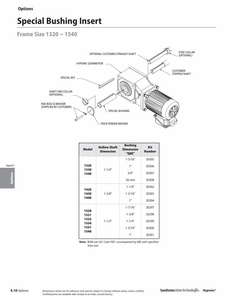
4.10 Options
OptionsO
ptio
ns
Hyponic®
Hyponic®
Special Bushing InsertFrame Size 1320 ~ 1540
SPECIAL BUSHING
THICK FENDER WASHER
CUSTOMER STEPPED SHAFT
SPECIAL KEY
HYPONIC GEARMOTOR
HEX-BOLT & WASHER(SUPPLIED BY CUSTOMER)
SHAFT END COLLAR(OPTIONAL)
OPTIONAL CUSTOMER STRAIGHT SHAFT STOP-COLLAR (OPTIONAL)
ModelHollow Shaft
Dimension
BushingDimension
"Q8E"
Kit Number
132013301340
1-1/4”
1-3/16” 30305
1” 30306
3/4” 30307
30 mm 30308
142014301440
1-3/8”
1-1/4” 30302
1-3/16” 30303
1” 30304
152015211522153015311540
1-1/2”
1-7/16” 30297
1-3/8” 30298
1-1/4” 30299
1-3/16” 30300
1” 30301
Note: BOM use SSC Code YBZ1 accompanied by Q8E with specifiedbore size.
Dimensions shown are for reference only and are subject to change without notice, unless certified.Certified prints are available after receipt of an order; consult factory.

Appendix
App
endi
x
Hyponic®
Appendix 5.1Hyponic®
Appendix5

5.2 Appendix
App
endi
x
Hyponic®
Appendix
Hyponic®
Shaft DimensionsSymbols: � Standard � Semi-standard
Consult factory for price and delivery.
Table 5.1 Hollow Shaft Dimensions (in.)
Bore Size (in.)
Frame Size
112012201230
132013301340
142014301440
152015211522153015311540
16301631163216331640
3/4 � � �
13/16 � �
7/8 � �
15/16 � �
1 � � � �
1-1/8 � � �
1-3/16 � � �
1-1/4 � � �
1-5/16 � �
1-3/8 � �
1-7/16 �[1] �
1-1/2 �
1-5/8 � �
1-11/16 � �
1-3/4 � �
1-7/8 �
1-15/16 �
2 �
2-1/16 �
2-1/8 �
2-3/16 �
Notes: [1] Special maximum bore size for frame size 1430 is 1-7/16”;maximum bore size for frame sizes 1420 and 1440 is 1-3/8”.
[2] Standard shaft dimension for T-type.[3] Plug-in shaft only, not available with foot.
Bore Size
(mm)
Frame Size
112012201230
132013301340
14201440
1430
152015211522153015311540
16301631163216331640
20 � � �
25 � � � �
30 � � � �
35 � � �
38 � �
40 � �
45 � �
50 �
55 �
Table 5.2 Hollow Shaft Optional Metric Bore Dimensions (mm)
Table 5.3 Solid Shaft Dimensions (in.)
Bore Size (in.)
Frame Size
112012201230
132013301340
142014301440
15201521[[33]]
1522[[33]]
153015311540
16301631163216331640
3/4 �
1 �
1-1/4 �
1-5/16
1-3/8 �
1-7/16
1-1/2 �[2]
1-3/4 �
2 �[3]

Appendix 5.3
App
endi
x
Hyponic®
Appendix
Hyponic®
Model Reduction Ratio (:1) Model Reduction Ratio (:1)
1120 5, 7, 10, 12, 15, 20, 25, 30, 40, 50, 60 1120 –
1220 5, 7, 10, 12, 15, 20, 25, 30, 40, 50, 60 1220 –
1230 – 1230 80, 100, 120, 150, 200, 240
1320 5, 7, 10, 12, 15, 20, 25, 30, 40, 50, 60 1320 –
1330 – 1330 80, 100, 120, 150, 200, 240
1340 300, 360, 480, 600, 720, 900, 1200, 1440 1340 –
1420 5, 7, 10, 12, 15, 20, 25, 30, 40, 50, 60 1420 –
1430 – 1430 80, 100, 120, 150, 200, 240
1440 300, 360, 480, 600, 720, 900, 1200, 1440 1440 –
1520 5, 7, 10, 12, 15, 20, 25, 30, 40, 50, 60 1520 –
1521 5, 7, 10, 12, 15, 20, 25 1521 –
1522 5, 7, 10, 12, 15 1522 –
1530 – 1530 80, 100, 120, 150, 200, 240
1531 – 1531 40, 50, 60, 80
1540 300, 360, 480, 600, 720, 900, 1200, 1440 1540 –
1630 – 1630 80, 100, 120
1631 – 1631 150, 200, 240
1632 30 1632 40, 50, 60
1633 20, 25 1633 30, 40
1640 300, 360, 480, 600, 720, 900, 1200, 1440 1640 –
CCW
CW ��
��
Figure 5.1 Figure 5.2
Table 5.4 Shaft Rotation Direction
Shaft Rotation
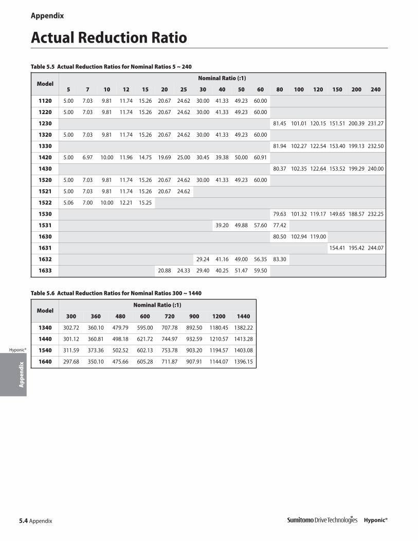
5.4 Appendix
App
endi
x
Hyponic®
Appendix
Hyponic®
Actual Reduction Ratio
Table 5.5 Actual Reduction Ratios for Nominal Ratios 5 ~ 240
ModelNominal Ratio (:1)
5 7 10 12 15 20 25 30 40 50 60 80 100 120 150 200 240
1120 5.00 7.03 9.81 11.74 15.26 20.67 24.62 30.00 41.33 49.23 60.00
1220 5.00 7.03 9.81 11.74 15.26 20.67 24.62 30.00 41.33 49.23 60.00
1230 81.45 101.01 120.15 151.51 200.39 231.27
1320 5.00 7.03 9.81 11.74 15.26 20.67 24.62 30.00 41.33 49.23 60.00
1330 81.94 102.27 122.54 153.40 199.13 232.50
1420 5.00 6.97 10.00 11.96 14.75 19.69 25.00 30.45 39.38 50.00 60.91
1430 80.37 102.35 122.64 153.52 199.29 240.00
1520 5.00 7.03 9.81 11.74 15.26 20.67 24.62 30.00 41.33 49.23 60.00
1521 5.00 7.03 9.81 11.74 15.26 20.67 24.62
1522 5.06 7.00 10.00 12.21 15.25
1530 79.63 101.32 119.17 149.65 188.57 232.25
1531 39.20 49.88 57.60 77.42
1630 80.50 102.94 119.00
1631 154.41 195.42 244.07
1632 29.24 41.16 49.00 56.35 83.30
1633 20.88 24.33 29.40 40.25 51.47 59.50
ModelNominal Ratio (:1)
300 360 480 600 720 900 1200 1440
1340 302.72 360.10 479.79 595.00 707.78 892.50 1180.45 1382.22
1440 301.12 360.81 498.18 621.72 744.97 932.59 1210.57 1413.28
1540 311.59 373.36 502.52 602.13 753.78 903.20 1194.57 1403.08
1640 297.68 350.10 475.66 605.28 711.87 907.91 1144.07 1396.15
Table 5.6 Actual Reduction Ratios for Nominal Ratios 300 ~ 1440
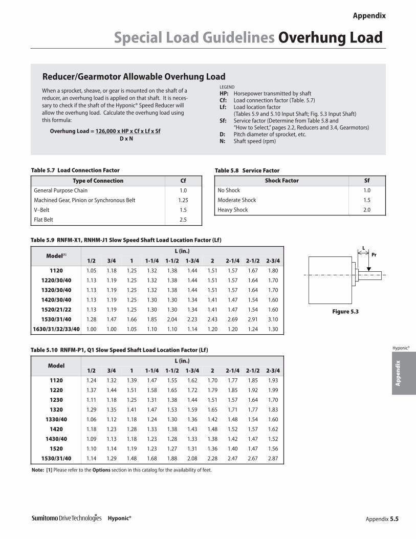
Appendix 5.5
App
endi
x
Hyponic®
Appendix
Hyponic®
Special Load Guidelines Overhung Load
Reducer/Gearmotor Allowable Overhung LoadWhen a sprocket, sheave, or gear is mounted on the shaft of areducer, an overhung load is applied on that shaft. It is neces-sary to check if the shaft of the Hyponic® Speed Reducer willallow the overhung load. Calculate the overhung load usingthis formula:
Overhung Load = 126,000 x HP x Cf x Lf x SfD x N
LEGEND
HP: Horsepower transmitted by shaftCf: Load connection factor (Table. 5.7)Lf: Load location factor
(Tables 5.9 and 5.10 Input Shaft; Fig. 5.3 Input Shaft)Sf: Service factor (Determine from Table 5.8 and
“How to Select,” pages 2.2, Reducers and 3.4, Gearmotors)D: Pitch diameter of sprocket, etc.N: Shaft speed (rpm)
Table 5.7 Load Connection Factor Table 5.8 Service Factor
Type of Connection Cf
General Purpose Chain 1.0
Machined Gear, Pinion or Synchronous Belt 1.25
V–Belt 1.5
Flat Belt 2.5
Shock Factor Sf
No Shock 1.0
Moderate Shock 1.5
Heavy Shock 2.0
Model[1]L (in.)
1/2 3/4 1 1-1/4 1-1/2 1-3/4 2 2-1/4 2-1/2 2-3/4
1120 1.05 1.18 1.25 1.32 1.38 1.44 1.51 1.57 1.67 1.80
1220/30/40 1.13 1.19 1.25 1.32 1.38 1.44 1.51 1.57 1.64 1.70
1320/30/40 1.13 1.19 1.25 1.32 1.38 1.44 1.51 1.57 1.64 1.70
1420/30/40 1.13 1.19 1.25 1.30 1.30 1.34 1.41 1.47 1.54 1.60
1520/21/22 1.13 1.19 1.25 1.30 1.30 1.34 1.41 1.47 1.54 1.60
1530/31/40 1.28 1.47 1.66 1.85 2.04 2.23 2.43 2.69 2.91 3.10
1630/31/32/33/40 1.00 1.00 1.05 1.10 1.10 1.14 1.20 1.20 1.24 1.30
Table 5.9 RNFM-X1, RNHM-J1 Slow Speed Shaft Load Location Factor (Lf)
ModelL (in.)
1/2 3/4 1 1-1/4 1-1/2 1-3/4 2 2-1/4 2-1/2 2-3/4
1120 1.24 1.32 1.39 1.47 1.55 1.62 1.70 1.77 1.85 1.93
1220 1.37 1.44 1.51 1.58 1.65 1.72 1.79 1.85 1.92 1.99
1230 1.11 1.18 1.25 1.31 1.38 1.44 1.51 1.57 1.64 1.70
1320 1.29 1.35 1.41 1.47 1.53 1.59 1.65 1.71 1.77 1.83
1330/40 1.06 1.12 1.18 1.24 1.30 1.36 1.42 1.48 1.54 1.60
1420 1.18 1.23 1.28 1.33 1.38 1.43 1.48 1.52 1.57 1.62
1430/40 1.09 1.13 1.18 1.23 1.28 1.33 1.38 1.42 1.47 1.52
1520 1.10 1.14 1.19 1.23 1.27 1.31 1.36 1.40 1.47 1.56
1530/31/40 1.14 1.29 1.48 1.68 1.88 2.08 2.28 2.47 2.67 2.87
Table 5.10 RNFM-P1, Q1 Slow Speed Shaft Load Location Factor (Lf)
PrL
Figure 5.3
Note: [1] Please refer to the Options section in this catalog for the availability of feet.

AppendixA
ppen
dix
Hyponic®
5.6 Appendix Hyponic®
Special Load Guidelines Inertia
Motor TypeMotor HP
1/8 1/4 1/3 1/2 3/4 1 1-1/2 2 3 5 7-1/2
3-PhaseWithout Brake 1.13 1.71 2.22 2.22 3.45 4.10 6.32 7.28 11.40 29.0 39.0
With Brake 1.20 1.88 2.32 2.32 3.79 4.44 7.11 8.03 12.70 32.70 42.70
Single-PhaseWithout Brake 1.71 2.22 – 4.10 – – – – – – –
With Brake 1.88 2.32 – 4.44 – – – – – – –
Inverter DutyWithout Brake 1.71 2.22 – 4.10 – 7.28 – 11.40 29.0 39.0 –
With Brake 1.88 2.32 – 4.44 – 8.03 – 12.70 32.70 42.70 –
Table 5.11 Gearmotor Moment of Inertia Units: pound•inch2
Table 5.12 Reducer Moment of Inertia, Ratios 5 ~ 240 Units: lbf•inch2
ModelReduction Ratio
5 7 10 12 15 20 25 30 40 50 60 80 100 120 150 200 240
1120 0.149 0.145 0.143 0.143 0.142 0.142 0.141 0.141 0.134 0.134 0.134 – – – – – –
1220 0.216 0.200 0.194 0.192 0.190 0.189 0.188 0.188 0.168 0.168 0.168 – – – – – –
1230 – – – – – – – – – – – 0.135 0.135 0.135 0.134 0.134 0.134
1320 0.351 0.336 0.323 0.317 0.310 0.304 0.302 0.300 0.238 0.238 0.237 – – – – – –
1330 – – – – – – – – – – – 0.169 0.168 0.168 0.166 0.166 0.166
1420 0.647 0.607 0.566 0.553 0.540 0.525 0.515 0.510 0.367 0.364 0.363 – – – – – –
1430 – – – – – – – – – – – 0.239 0.238 0.238 0.186 0.185 0.185
1520 2.977 2.840 2.743 2.704 2.656 2.616 2.599 2.582 2.009 2.008 2.004 – – – – – –
1530 – – – – – – – – – – – 0.369 0.366 0.365 0.337 0.336 0.336
1531 – – – – – – – – 1.135 1.135 1.135 1.135 – – – – –
Table 5.12 Reducer Moment of Inertia, Ratios 300 ~ 1440 Units: lbf•inch2
ModelReduction Ratio
300 360 480 600 720 900 1200 1440
1340 0.135 0.134 0.135 0.135 0.134 0.134 0.134 0.134
1440 0.168 0.168 0.168 0.168 0.168 0.166 0.166 0.166
1540 0.238 0.237 0.238 0.237 0.186 0.186 0.185 0.185
1640 0.366 0.365 0.368 0.365 0.364 0.337 0.336 0.336

Appendix
Construction & Nameplate
App
endi
x
Hyponic®
Appendix 5.7Hyponic®
6 5 4 3 2
121110987
Construction
Figure 5.4 Hollow Shaft Type Example (RNYM1-1530-120)
Part No. Description Part No. Description Part No. Description Part No. Description
1 Casing (1) 4 Gear 7 Bearing 10 Output shaft
2 Gear 5 Pinion shaft 8 Bearing 11 Oil seal
3 Pinion shaft 6 Hypoid pinion shaft 9 Hypoid gear 12 Casing (2)
Nameplate
Figure 5.5
Table 5.13 Hollow Shaft Type Parts

1. Mounting the Shaft in the Hollow Bore
a. After coating the shaft and the reducer hollow bore with molybde-num disulfide, insert the shaft into the bore.
b. A clearance fit is standard. A tight fit is recommended for severeapplications. For tight-fit applications, tap the end of the hollowshaft with a rubber mallet to aid insertion into the bore. Using fixtures b - e shown in Figure 5.6 is also recommended for easyassembly.
2. Securing the Shaft in the Hollow Bore
a. Refer to Figure 5.7 and Table 5.14 for details on securing a stagedshaft.
b. Refer to Figure 5.8 and Table 5.14 for details on securing a straightshaft using a spacer.
3. Shaft Removal - Fixtures i - k shown in Figure 5.9 are recommendedfor easy removal of the shaft. The shaft should be designed to allowuse of these fixtures.
5.8 Appendix
App
endi
x
Hyponic®
Appendix
Hyponic®
Mounting
Dimensions shown are for reference only and are subject to change without notice.
Figure 5.6 Driven Shaft Mounting Figure 5.7 Secured by Staged Driven Shaft
Figure 5.8 Secured by Spacer Figure 5.9 Driven Shaft Removal
Table 5.14 Driven Shaft Mounting and Removal Detail (in.)
Model
Bore Size Recommended Shaft Size Recommended Component Size[1]
øDL LH LG LF L1 L2 L3 L4 L5
a b c d
min. max A1 Nut ThreadThrust
Bearing1120 0.750 0.751 3.23 2.64 2.01 1.22 2.36 0.16 1.37 #10-32UNF 0.63 0.20 #10-32UNF #10-32UNF x 5.91 51100
1220 1.000 1.001 3.62 2.76 2.13 1.50 2.36 0.28 1.98 5/16-18UNC 0.79 0.28 5/16-18UNC 5/16-18UNC x 5.91 51100
1230 1.000 1.001 3.94 3.07 2.44 1.50 2.68 0.28 1.98 5/16-18UNC 0.79 0.28 5/16-18UNC 5/16-18UNC x 5.91 51100
1320/30/40 1.250 1.252 4.33 3.46 2.52 1.81 2.80 0.28 2.10 5/16-18UNC 0.79 0.28 5/16-18UNC 5/16-18UNC x 5.91 51100
1420/30/40 1.375 1.377 5.43 4.41 3.39 2.05 3.66 0.39 2.32 3/8-16UNC 0.98 0.31 3/8-16UNC 3/8-16UNC x 9.45 512011520/21/22/
30/31/401.500 1.502 6.14 5.12 3.86 2.28 4.09 0.39 3.49 1/2-13UNC 1.18 0.39 1/2-13UNC 1/2-13UNC 9.45 51202
1630/31/32/33/40
2.000 2.002 8.82 7.24 5.83 2.99 6.26 0.47 3.53 5/8-11UNC 1.57 0.51 5/8-11UNC 5/8-11UNC x 11.81 51204
Model
Model Recommended Component Size [1]
e f g h i j k
A2 Bolt RetainingRing O.D. x I.D. Bolt A3 A4 A5 A6 A7 A8
1120 0.59 #10-32UNF x 0.98 0.75 0.75 x 0.28 5/16-18UNC x 4.72 0.16 0.64 0.75 -0.004-0.012 4.762 5/16-18UNC 2
1220 0.51 5/16-18UNC x 1.38 1.00 1.00 x 0.39 1/2-13UNC x 4.72 028 0.86 1.00 -0.004-0.012 6.35 1/2-13UNC 2
1230 0.51 5/16-18UNC x 1.57 1.00 1.00 x 0.39 1/2-13UNC x 4.72 0.28 0.86 1.00 -0.004-0.012 6.35 1/2-13UNC 2
1320/30/40 0.51 5/16-18UNC x 1.77 1.25 1.25 x 0.67 5/8-16UNC x 5.91 0.51 1.11 1.25 -0.004-0.012 6.35 5/8-16UNC 3
1420/30/40 0.59 3/8-16UNC x 2.17 1.38 1.37 x 0.75 5/8-16UNC x 7.87 0.51 1.20 1.37 -0.004-0.012 7.938 5/8-16UNC 5
1520/21/22/30/31/40
0.55 1/2-13UNC x 2.56 1.50 1.50 x 1.02 3/4-10UNC x 7.87 0.63 1.29 1.50 -0.004-0.012 9.525 3/4-10UNC 5
1630/31/32/33/40
1.02 5/8-11UNC x 2.95 2.00 2.17 x 0.98 1-8UNC x 9.45 0.75 1.72 2.00 -0.004-0.012 12.7 1-8UNC 5
Note: [1] Parts a – k are not supplied by Sumitomo Drive Technologies.

Mounting continued
Appendix 5.9
App
endi
x
Hyponic®
Appendix
Hyponic®
Recommended Shaft Tolerances for Hollow Bore Hyponic®
According to JIS standard and based on loading conditions, recommendedshaft tolerances for hollow bore Hyponic® are:
• Steady, uniform loads: JIS h6/js6 (low shock load)• Shock load or large overung load: JIS js6/k6 (high shock load)• Snap ring size is in accordance with: JIS B2804C
Refer to tables 5.15 and 5.16 for corresponding shaft diameters.
Table 5.16 Inch Bore Shaft Diameters (in.)
Bore Size
Low Shock LoadJIS h6/js6
High Shock LoadJIS js6/k6
Min Max Min Max3/4 0.74950 0.75025 0.74975 0.75060
13/16 0.81200 0.81275 0.81225 0.813107/8 0.87450 0.87525 0.87475 0.87560
15/16 0.93700 0.93775 0.93725 0.938101 0.99950 1.00025 0.99975 1.00060
1-1/8 1.12450 1.12525 1.12475 1.125601-3/16 1.18700 1.18775 1.18725 1.188101-1/4 1.24940 1.25030 1.24970 1.25070
1-5/16 1.31190 1.31280 1.31220 1.313201-3/8 1.37440 1.37530 1.37470 1.37570
1-7/16 1.43690 1.43780 1.43720 1.438201-1/2 1.49940 1.50030 1.49970 1.500701-5/8 1.62440 1.62530 1.62470 1.62570
1-11/16 1.68690 1.68780 1.68720 1.688201-3/4 1.74940 1.75030 1.74970 1.750701-7/8 1.87440 1.87530 1.87470 1.87570
1-15/16 1.93690 1.93780 1.93720 1.938202 1.99930 2.00030 1.99970 2.00080
2-1/16 2.06180 2.06280 2.06220 2.063302-1/8 2.12430 2.12530 2.12470 2.12580
2-3/16 2.18680 2.18780 2.18720 2.18830
Table 5.15 Metric Bore Shaft Diameters (mm)
Bore Size
Low Shock LoadJIS h6/js6
High Shock LoadJIS js6/k6
Min Max Min Max20 19.9870 20.0065 19.9935 20.015025 24.9870 25.0065 24.9935 25.015030 29.9870 30.0065 29.9935 30.015035 34.9840 35.0065 34.9935 35.018038 37.9840 38.0080 37.9920 38.018040 39.9840 40.0080 39.9920 40.018045 44.9840 45.0080 44.9920 45.018050 49.9840 50.0080 49.9920 50.018055 54.9810 55.0095 54.9905 55.0210
4. Securing the Hyponic® Drive to Prevent Movement Away from the Machine Side (Figures 5.10 – 5.12)
Figure 5.10 Secured by Spacer andSnap Ring
Figure 5.11 Secured by End Plate Figure 5.12 Secured by Set Screwand Collar
5. Flange Mounting and Casing Bottom Mounting (optional)Handle with care. Do not apply excessive force to the driven shaft or hollow shaft by twisting the Hyponic® casing. Excessive force on the Hyponic®and bearing unit may damage internal parts.
Hyponic® hollowshaft model
Bearing unit
Figure 5.13 Flange Mounting Surface
Correct
Hyponic® hollowshaft model
Bearing unit
Incorrect: Poor concentricity of drivenshaft and mounting flange
Hyponic® hollowshaft model
Bearing unit
Incorrect: Poor perpendicularity of drivenshaft center and mounting flange surface

5.10 Appendix
App
endi
x
Hyponic®
Appendix
Hyponic®
Accessories Output Shaft Safety Cover, Torque Arm
Output Shaft Safety CoverIncluded with all hollow bore models, the output shaft safety cover is made of plastic and may bemounted on either the right or left side.
Figure 5.14 Frame Size 1100
Figure 5.15 Frame Sizes 1200 ~1600
Table 5.17 Output Shaft Safety Cover DimensionsSymbols: M: Screw size P: Thread pitch L: Thread length P.C.D: Mounting pitch N: Quantity
ModelSafety Cover Output
Shaft End Fig. #A øB C° D t øP.C.D N MxPxL (mm) øE
1100 0.39 2.20 45 R0.12 0.08 (screw not required for this model) 1.18 5.6
1200 0.83 2.32 5 R0.20 0.08 2.76 2 M3x0.5x6 1.57 5.7
1300 0.83 2.64 5 R0.20 0.08 3.07 2 M3x0.5x6 1.77 5.7
1400 1.18 3.03 5 R0.20 0.08 3.46 2 M3x0.5x6 2.17 5.7
1500 1.18 3.54 5 R0.20 0.08 4.06 2 M3x0.5x6 2.56 5.7
1600 1.57 4.48 5 R0.20 0.08 5.31 2 M3x0.5x6 3.74 5.7
Torque ArmFigure 5.16 Hyponic® Torque Arm Recommended Dimensions
Table 5.18 Hyponic® Torque Arm Recommended Dimensions (in.)
ModelLength Bore
Stop Hole
Mounting Pitch MountingHole Thickness
AR øH øD a b ød
1120 3.15 2.13 0.35 1.65 1.26 0.28 0.13
1220 3.94 3.15 0.43 2.24 1.57 0.35 0.18
1230 3.94 3.15 0.35 2.56 1.57 0.35 0.24
1320 4.72 3.43 0.55 2.44 1.81 0.43 0.18
1330, 1340 5.12 3.43 0.43 3.11 1.85 0.43 0.35
1420 5.51 3.82 0.71 2.95 2.24 0.55 0.24
1430, 1440 6.30 3.82 0.55 3.62 2.13 0.55 0.35
1520, 1521, 1522 5.91 4.41 0.87 3.15 2.76 0.55 0.35
1530, 1531, 1540 7.87 4.41 0.71 4.29 2.52 0.71 0.35
1630, 1631, 1632, 1633, 1640 11.02 5.98 0.87 5.71 3.35 0.87 0.47
Dimensions shown are for reference only and are subject to change without notice.
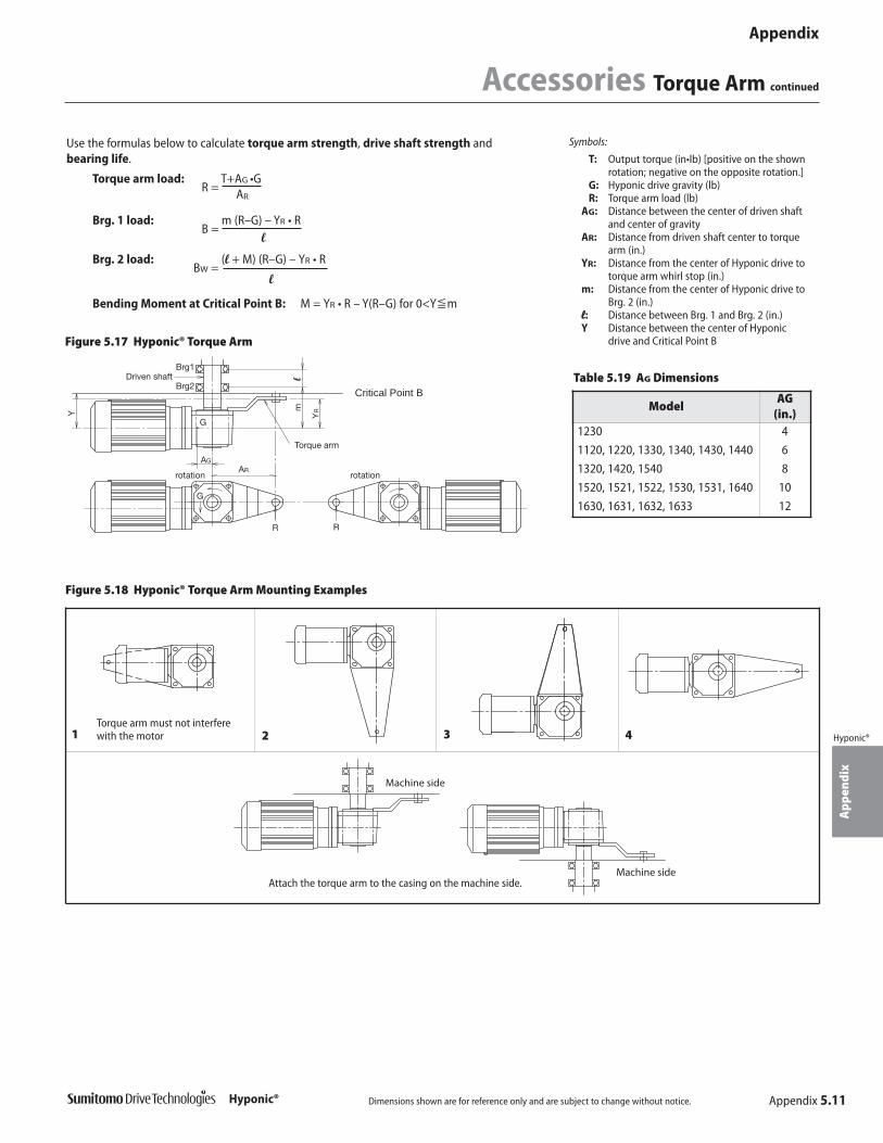
Appendix 5.11
App
endi
x
Hyponic®
Appendix
Hyponic®
Accessories Torque Arm continued
Symbols:
T: Output torque (in•lb) [positive on the shownrotation; negative on the opposite rotation.]
G: Hyponic drive gravity (lb)R: Torque arm load (lb)
AG: Distance between the center of driven shaftand center of gravity
AR: Distance from driven shaft center to torquearm (in.)
YR: Distance from the center of Hyponic drive totorque arm whirl stop (in.)
m: Distance from the center of Hyponic drive toBrg. 2 (in.)
ll: Distance between Brg. 1 and Brg. 2 (in.)Y Distance between the center of Hyponic
drive and Critical Point B
Critical Point B
l
Figure 5.17 Hyponic® Torque Arm
Table 5.19 AG Dimensions
ModelAG
(in.)1230 4
1120, 1220, 1330, 1340, 1430, 1440 6
1320, 1420, 1540 8
1520, 1521, 1522, 1530, 1531, 1640 10
1630, 1631, 1632, 1633 12
Figure 5.18 Hyponic® Torque Arm Mounting Examples
Machine side
Machine side
1 2 3 4Torque arm must not interfere with the motor
Attach the torque arm to the casing on the machine side.
Dimensions shown are for reference only and are subject to change without notice.
Use the formulas below to calculate torque arm strength, drive shaft strength andbearing life.
Torque arm load:R =
T+AG •GAR
Brg. 1 load:B =
m (R–G) – YR • Rl
Brg. 2 load:BW =
(l + M) (R–G) – YR • R
l
Bending Moment at Critical Point B: M = YR • R – Y(R–G) for 0<Y�m

5.12 Appendix
App
endi
x
Hyponic®
Appendix
Hyponic®
Accessories Torque Arm continued
Torque Arm Mounting:
1. Attach the torque arm to the Hyponic® casing on the machine side using hex socket head capscrews. Refer to Table 5.20 for bolt sizes.
2. Leave some clearance between the torque arm and machine, and the torque arm and mount-ing bolt, so excessive force will not be applied to the Hyponic® and driven shaft. Do not securethe torque arm with the torque arm bolt; it may damage the bolt, torque arm, Hyponic® or the machine
3. For frequent start/stop applications, or repeated normal/reverse operations, use a rubber bushing between the torque arm and mounting bolt (or spacer) to absorb the shock.
No clearance between torque arm and machine
Leave some clearance
Special bolt or pin
Flat washer
Spacer
Torque Arm
Figure 5.19 Hyponic® Torque Arm Clearance
Model Bolt
1120, 1230 M8
1220, 1330, 1340 M10
1320, 1430, 1440 M12
1420, 1530, 1531 M161520, 1521, 1522, 1630, 1631, 1632, 1633, 1640 M20
Table 5.20 Torque Arm Bolt Sizes
CorrectAdjust clearance according tomovement of machine
IncorrectExcessive force on the torquearm bolt, machine and Hyponic®may cause damage
LubricationHyponic® drives are filled with long-life grease and sealed, so replenishment is practically unnec-essary, but overhaul in approximately 20,000 hours or three to five years of operation will providelonger service life. Operating conditions affect oil seal durability. Under severe conditions, theymay require changing in less than 20,000 hours or three years of operation. Gearmotors must beoverhauled at factory-authorized locations.
Paint and Rust-proofing Specifications
Paint Classification Paint Name Paint Color Resin Type Dry Time (hrs.)
Standard Speed Dry DTM Water-Based Enamel Blue Water-Based
Acrylic Polymer 1 – 1½
Epoxy (optional) Heavy-Duty Epoxy Blue Polymide Converted Epoxy 4 – 6
FDA-USDA (optional) Food and Beverage Industry Coating High Gloss White Modified Alkyd 4 – 7
Table 5.21 Paint Specifications
Table 5.22 Rust-proofing Specifications
Lubrication Type Grease Oil
Rust-Proofing Period 1 Year 6 Months
Storage Condition Indoor environment that is relatively free of humidity, dust,extreme temperature fluctuation. corrosive gas, etc.
• All completely assembled models receive rust-proofing treatment prior to shipment.
• All oil-lubricated models for export receive rust-proofing treatment that is effective for 6–12months. Please specify ”export Rust-proofing” for all export models.
• Please consult factory for storage longer than those listed in Table 5.22 or in the event of adversestorage conditions.

Appendix 5.13
App
endi
x
Hyponic®
Appendix
Hyponic®
• Conduit Box Specifications• Standard Motor Characteristics• Brakemotor Characteristics
Motor
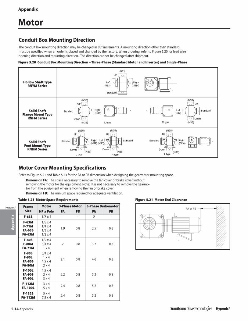
5.14 Appendix
App
endi
x
Hyponic®
Appendix
Hyponic®
Motor
Conduit Box Mounting DirectionThe conduit box mounting direction may be changed in 90° increments. A mounting direction other than standardmust be specified when an order is placed and changed by the factory. When ordering, refer to Figure 5.20 for lead wireopening direction and mounting direction. The direction cannot be changed after shipment.
Up
(N33) (N34)
(N35)
Left Right
Standard
Up
Down
RightStandard
Up
Down
StandardLeft
L type R type(N36)
(N34)
(N35)
(N37)
(N36)
(N35)
Right
Up
Down
Up
Down
Up
Down
L type R type T type
Right LeftStandard StandardStandard(N33)(N34)
(N35)
(N36) (N36)
(N35)
(N36)
(N34)
(N35)
Figure 5.20 Conduit Box Mounting Direction – Three-Phase (Standard Motor and Inverter) and Single-Phase
Hollow Shaft TypeRNYM Series
Solid Shaft Flange Mount Type
RNFM Series
Solid Shaft Foot Mount Type
RNHM Series
Motor Cover Mounting SpecificationsRefer to Figure 5.21 and Table 5.23 for the FA or FB dimension when designing the gearmotor mounting space.
Dimension FA: The space necessary to remove the fan cover or brake cover withoutremoving the motor for the equipment. Note: It is not necessary to remove the gearmo-tor from the equipment when removing the fan or brake cover.Dimension FB: The minium space required for adequate ventilation.
Figure 5.21 Motor End Clearance
Frame Size
Motor 3-Phase Motor 3-Phase Brakemotor
HP x Pole FA FB FA FB
F-63S 1/8 x 4 - - 2 -
F-63MF-71MFA-63SFA-63M
1/8 x 41/4 x 41/3 x 41/2 x 4
1.9 0.8 2.5 0.8
F-80SF-80M
FA-71M
1/2 x 43/4 x 4
1 x 42 0.8 3.7 0.8
F-90SF-90L
FA-80SFA-80M
3/4 x 41 x 4
1.5 x 42 x 4
2.1 0.8 4.6 0.8
F-100LFA-90SFA-90L
1.5 x 42 x 43 x 4
2.2 0.8 5.2 0.8
F-112MFA-100L
3 x 45 x 4 2.4 0.8 5.2 0.8
F-132SFA-112M
5 x 47.5 x 4 2.4 0.8 5.2 0.8
Table 5.23 Motor Space Requirements
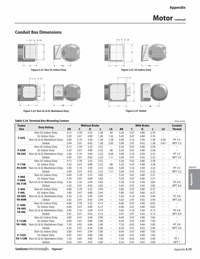
Appendix 5.15
App
endi
x
Hyponic®
Appendix
Hyponic®
Motor continued
Conduit Box Dimensions
Figure 5.22 Non-UL Indoor Duty Figure 5.23 UL Indoor Duty
Figure 5.24 Non-UL & UL Washdown Duty Figure 5.25 Global
Table 5.24 Terminal Box Mounting Centers Units: inches
Frame Size
Duty RatingWithout Brake With Brake Conduit
ThreadAB C D L LX AB C D L LX
F-63S
Non-UL Indoor Duty 4.13 3.78 3.35 1.38 .30 5.20 5.67 4.80 2.76 – –UL Indoor Duty 5.20 5.67 4.80 1.38 1.02 5.20 5.67 4.80 2.76 – –
Non-UL & UL Washdown Duty 5.00 5.16 3.94 1.38 1.58 5.00 5.16 3.94 1.38 0.20 PF 1/2Global 5.04 5.91 4.92 1.38 2.05 5.04 5.91 4.92 1.38 0.67 NPT 1/2
F-63M FA-63S
Non-UL Indoor Duty 4.13 3.78 3.35 2.32 – 5.20 5.67 4.80 3.58 – –UL Indoor Duty 5.20 5.67 4.80 2.32 .08 5.20 5.67 4.80 3.58 – –
Non-UL & UL Washdown Duty 5.00 5.16 3.94 2.32 0.64 5.00 5.16 3.94 2.32 – PF 1/2Global 5.04 5.91 4.92 2.32 1.11 5.04 5.91 4.92 2.32 – NPT 1/2
F-71MFA-63M
Non-UL Indoor Duty 4.13 3.78 3.35 2.32 – 5.20 5.67 4.80 3.58 – –UL Indoor Duty 5.20 5.67 4.80 2.32 .08 5.20 5.67 4.80 3.58 – –
Non-UL & UL Washdown Duty 5.00 5.16 3.94 2.32 0.64 5.00 5.16 3.94 2.32 – PF 1/2Global 5.04 5.91 4.92 2.32 1.11 5.04 5.91 4.92 2.32 – NPT 1/2
F-80S F-80M
FA-71M
Non-UL Indoor Duty 4.49 3.78 3.35 3.82 – 5.59 5.67 4.80 5.51 – –UL Indoor Duty 5.59 5.67 4.80 3.82 – 5.59 5.67 4.80 5.51 – –
Non-UL & UL Washdown Duty 5.36 5.16 3.94 3.82 – 5.36 5.16 3.94 3.82 – PF 3/4Global 5.43 5.91 4.92 3.82 – 5.43 5.91 4.92 3.82 – NPT 3/4
F-90S F-90L
FA-80SFA-80M
Non-UL Indoor Duty 4.68 3.78 3.35 3.94 – 5.80 5.67 4.80 6.37 – –UL Indoor Duty 5.80 5.67 4.80 3.94 – 5.80 5.67 4.80 6.37 – –
Non-UL & UL Washdown Duty 5.56 5.16 3.94 3.94 – 5.56 5.16 3.94 3.94 – PF 3/4Global 5.63 5.91 4.92 3.94 – 5.63 5.91 4.92 3.94 – NPT 3/4
F-100LFA-90SFA-90L
Non-UL Indoor Duty 4.96 3.78 3.35 4.13 – 6.06 5.67 4.80 6.65 – –UL Indoor Duty 6.06 5.67 4.80 4.13 – 6.06 5.67 4.80 6.65 – –
Non-UL & UL Washdown Duty 5.84 5.16 3.94 4.13 – 5.84 5.16 3.94 4.13 – PF 3/4Global 5.91 5.91 4.92 4.13 – 5.91 5.91 4.92 4.13 – NPT 3/4
F-112MFA-100L
Non-UL Indoor Duty 5.80 4.41 3.94 5.00 – 6.69 5.67 4.80 7.83 – –UL Indoor Duty 6.69 5.67 4.80 5.00 – 6.69 5.67 4.80 7.83 – –
Non-UL & UL Washdown Duty 7.20 6.02 4.84 5.00 – 7.20 6.02 4.84 5.00 – PF 3/4Global 6.54 5.91 4.92 5.00 – 6.54 5.91 4.92 5.00 – NPT 3/4
F-132SFA-112M
Non-UL Indoor Duty 5.80 4.41 3.94 5.00 – 6.69 5.67 4.80 7.83 – –UL Indoor Duty 6.69 5.67 4.80 5.00 – 6.69 5.67 4.80 7.83 – –
Non-UL & UL Washdown Duty 7.20 6.02 4.84 5.00 – 7.20 6.02 4.84 5.00 – PF 1Global 6.54 5.91 4.92 5.00 – 6.54 5.91 4.92 5.00 – NPT 1

5.16 Appendix
App
endi
x
Hyponic®
Appendix
Hyponic®
Motor continued
Standard Motor DataFull load ratings and amperage for Hyponic® gearmotors are listed in Tables 5.25 through 5.27. These ratingsare based on the motors’ design values. If additional information is required, please consult the factory.
Table 5.26 Three-Phase 230/460V, Synchronous Speed 1800 RPM, 60 Hz, Continuous Duty, TEFC
HPFrame
Size
Full Load Current (A) StartingTorque
(% of FL)
BreakdownTorque
(% of FL)
Efficiency%
PowerFactor
%
NEMACode
Letter
Inertia WR2
lb-in2Rated Torque Full Load Starting% of FLRPM in-lbs 230V 460V
1/8 [1] F-63S 1730 4.55 0.66 0.33 424 326 308 63.3 59.5 K 1.111/4 F-63M 1730 9.09 1.12 0.56 464 300 287 69.2 64.8 K 1.71
1/3F-63M 1700 12.2 1.24 0.62 411 237 226 70.1 70.9 G 1.71F-71M 1770 11.7 1.85 0.93 530 484 454 67.2 50 N 2.22
1/2 F-71M 1750 18 2.15 1.08 456 295 276 71.5 69.6 J 2.223/4 F-80S 1730 27.4 2.47 1.24 498 266 261 76.5 73 H 3.45
1 F-80M 1740 36.2 3.38 1.69 521 278 303 76.9 72.3 H 4.11.5 F-90S 1720 54.9 4.66 2.33 614 273 290 79.8 74.4 J 6.322 F-90L 1740 72.3 6.07 3.04 606 263 275 81.9 75.6 J 7.283 F-100L 1730 109 8.5 4.25 645 277 311 83.9 77.8 J 11.45 F-112M 1730 182 13.1 6.55 702 278 293 85.8 82.2 J 29
7.5 F-132S 1710 276 18.2 9.08 659 223 252 86.2 88.2 H 39
Table 5.25 Single-Phase 115/230V, Synchronous Speed 1800 RPM, 60 Hz, Continuous Duty, TEFC
HP VoltageFrame
Size
Full Load StartingCurrent % of FL
StartingTorque %
of FL
BreakdownTorque % of FL
Efficiency%
PowerFactor
%
NEMACode
Letter
Inertia WR2
lb-in2Speed Torque CurrentRPM in-lbs Amp
1/8 115V FSU-63M 1760 4.46 2.2 536 326 311 57.7 67.4 M 1.71230V 1.1 564 340 318 57.1 68.0 N
1/4 115V FSU-71M 1760 8.96 3.6 586 261 281 57.6 98.3 L 2.22230V 1.8 589 256 286 57.4 98.1 L
1/3 115V FS-80M 1770 11.8 4.6 815 454 388 57.6 82.4 P 4.10230V 2.4 758 387 363 53.5 83.6 P
1/2 115V FS-80M 1750 17.9 5.8 643 331 277 67.6 89.5 K 4.10230V 3 633 283 274 65.0 88.6 K
Table 5.27 AF Motor, 230/460V, Continuous Duty, Constant Torque 10:1 Speed Range, TEFC
HPFrame
SizeWiring
Full LoadTorque in-lbs
60 Hz 6 Hz No Load Current@ 60 Hz
Inertia WR2
lb-in2Voltage Volt
CurrentAmp
Speed RPM
VoltageVolt
CurrentAmp
Speed RPM
1/8 FA-63S High Voltage 4.77 460 0.45 1770 68 0.37 125 0.45 1.71Low Voltage 230 0.9 34 0.74 0.89
1/4 FA-63M High Voltage 9.6 460 0.91 1765 68 0.75 130 0.84 2.22Low Voltage 230 1.8 34 1.5 1.67
1/3 FA-63M High Voltage 12 460 0.94 1760 68 0.77 90 0.84 2.22Low Voltage 230 1.9 34 1.5 1.67
1/2 FA-71M High Voltage 19.2 460 1.3 1750 70 1.1 115 1.18 4.10Low Voltage 230 2.5 35 2.2 2.36
3/4 FA-80S High Voltage 26.3 460 1.7 1760 64 1.6 135 1.50 6.32Low Voltage 230 3.3 32 3.1 3.00
1 FA-80M High Voltage 35.8 460 2.1 1755 62 1.9 120 1.87 7.28Low Voltage 230 4.3 31 3.9 3.74
1.5 FA-90S High Voltage 52.6 460 2.9 1755 64 2.9 135 2.40 11.4Low Voltage 230 5.8 32 5.8 4.80
2 FA-90L High Voltage 72.4 460 3.4 1740 66 3.2 105 2.40 11.4Low Voltage 230 6.7 33 6.5 4.80
3 FA-100L High Voltage 105 460 4.6 1760 62 4.7 140 3.15 29Low Voltage 230 9.2 31 9.3 6.30
5 FA-112M High Voltage 178 460 6.5 1740 64 7.3 100 2.94 39Low Voltage 230 13 32 14.6 5.88
Note: [1] 1/8 HP, Frame F-63S does not have a fan.

Appendix 5.17
App
endi
x
Hyponic®
Appendix
Hyponic®
Motor continued
CSA Approved Motor Data
Table 5.29 EPACT/EEV Efficiency Motors, CSA Approved230/460V, Synchronous Speed 1800 RPM, 60 Hz, Continuous Duty, TEFC
Table 5.28 CSA Approved Motors230/460V, Synchronous Speed 1800 RPM, 60 Hz, Continuous Duty, TEFC
HPFrame
Size
Full Load Current (A) Starting Breakdown Power NEMAInertia WR2
lb•in2Rated RPM
Torquein•lbs
Full Load No Load Starting Torque Torque Efficiency Factor Code230V 460V % of FL % of FL (% of FL) (% of FL) % % Letter
1/8 [1] F-63S 1720 4.59 0.71 0.35 90% 451% 378% 393% 65.5% 54.1% M 1.111/4 F-63M 1730 9.10 1.20 0.60 86% 450% 309% 343% 69.4% 60% K 1.711/3 F-63M 1710 12.20 1.30 0.65 79% 415% 244% 272% 71.3% 67.4% H 1.711/2 F-71M 1700 18.60 2.10 1.10 81% 481% 343% 331% 75.2% 63.1% J 2.223/4 F-80S 1700 28.20 2.60 1.30 71% 512% 263% 272% 75.4% 71.4% H 3.45
1 F-80M 1700 37.10 3.60 1.80 75% 572% 341% 315% 78.0% 66.8% K 4.10
HPFrame
Size
Full Load Current (A) Starting Breakdown Power NEMAInertia WR2
lb•in2Rated RPM
Torquein•lbs
Full Load No Load Starting Torque Torque Efficiency Factor Code230V 460V % of FL % of FL (% of FL) (% of FL) % % Letter
1 FA-80M 1740 36.3 3.24 1.62 67% 676% 331% 378% 84.5% 68.7% K 7.281.5 FA-90S 1740 54.4 4.58 2.29 65% 679% 319% 364% 85.7% 71.1% K 11.42 FA-90L 1730 72.8 5.81 2.91 60% 714% 271% 306% 86.6% 74.9% K 11.43 FA-100L 1750 108 8.1 4.05 57% 879% 310% 406% 89.1% 76.4% L 29.05 FA-112M 1740 181 12.7 6.35 45% 781% 302% 330% 89.5% 81.6% J 39.0
Note: [1] 1/8 HP is TENV.
Table 5.31 EPACT/EEV Efficiency Motors, CSA Approved575V, Synchronous Speed 1800 RPM, 60 Hz, Continuous Duty, TEFC
Table 5.30 CSA Approved Motors575V, Synchronous Speed 1800 RPM, 60 Hz, Continuous Duty, TEFC
HPFrame
Size
Full Load Current (A) Starting Breakdown Power NEMAInertia WR2
lb•in2Rated RPM
Torquein•lbs
Full No Load Starting Torque Torque Efficiency Factor CodeLoad % of FL % of FL (% of FL) (% of FL) % % Letter
1/8** F-63S 1720 4.59 0.28 90% 458% 376% 391% 65.3% 54.1% M 1.111/4 F-63M 1720 9.17 0.48 86% 459% 316% 340% 69.4% 60.3% K 1.711/3 F-63M 1710 12.20 0.52 79% 422% 250% 270% 71.3% 67.4% H 1.711/2 F-71M 1700 18.60 0.79 76% 468% 309% 300% 75.8% 67.4% J 2.223/4 F-80S 1700 28.20 1.00 74% 530% 260% 268% 75.1% 71.6% H 3.45
1 F-80M 1680 37.60 1.30 65% 508% 252% 256% 78.1% 74.9% H 4.10
HPFrame
Size
Full Load Current (A) Starting Breakdown Power NEMAInertia WR2
lb•in2Rated RPM
Torquein•lbs
Full No Load Starting Torque Torque Efficiency Factor CodeLoad % of FL % of FL (% of FL) (% of FL) % % Letter
1 FA-80M 1740 36.1 1.29 70% 690% 320% 379% 84.8% 68.2% K 7.281.5 FA-90S 1740 54.4 1.84 63% 674% 319% 364% 85.7% 71.1% K 11.42 FA-90L 1730 72.7 2.36 59% 703% 326% 371% 86.1% 73.6% K 11.43 FA-100L 1750 108 3.26 50% 844% 354% 417% 87.9% 78.5% L 29.05 FA-112M 1740 181 5.17 39% 774% 295% 346% 88.7% 81.7% J 39.0
Dimensions for 575 and CSA units may be different than those specified in Section 3, please consult factory.

5.18 Appendix
App
endi
x
Hyponic®
Appendix
Hyponic®
Motor continued
Standard Wiring DiagramsTable 5.32 lists the typical wiring configuration by motor type and Figures 5.26 - 5.28 illustratethe wiring diagrams for our standard motors. For additional information please refer to themotor name plate. Due to changes in design features, this diagram may not always agree withthat on the motor. If different, the motor diagram found inside the conduit box cover is correct.
3-Phase Motors (230/460 V)
Single Phase Motors
Figure 5.26 Wye-Connected Figure 5.27 Delta-Connected
Line 208/230V 60Hz Line 460V 60Hz Line 208/230V 60Hz Line 460V 60Hz
Line 115V Line 230V or 208V
Figure 5.28 Single Phase Motor Wiring Diagram
Motor Standard Inverter CSA HP x Pole Motor Duty [2] Motor
1/8 x 4
WYEWYE
WYE1/4 x 41/3 x 41/2 x 4 DELTA3/4 x 4
WYE
1 x 41.5 x 42 x 43 x 45 x 4
DELTA7.5 x 4 DELTA DELTA
Table 5.32 Typical 230/460V Wiring Configuration by Motor Type [1]
Notes: [1] Typical wiring configuration is shown and may be subject to change. For actual wiring diagram,please check diagram on motor
[2] Inverter Duty refers to AF-Motor Series rated for 10:1 constant torque speed range.
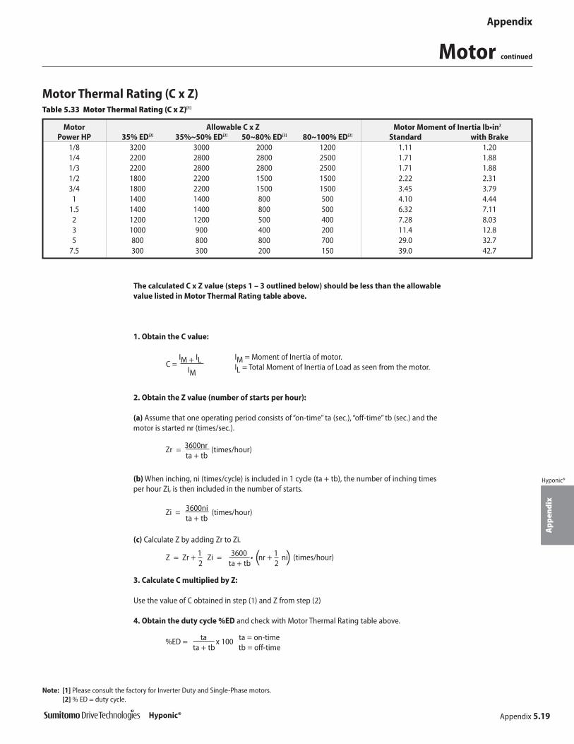
Appendix 5.19
App
endi
x
Hyponic®
Appendix
Hyponic®
Motor continued
Motor Thermal Rating (C x Z)
Motor Allowable C x Z Motor Moment of Inertia lb•in2
Power HP 35% ED[2] 35%~50% ED[2] 50~80% ED[2] 80~100% ED[2] Standard with Brake1/8 3200 3000 2000 1200 1.11 1.201/4 2200 2800 2800 2500 1.71 1.881/3 2200 2800 2800 2500 1.71 1.881/2 1800 2200 1500 1500 2.22 2.313/4 1800 2200 1500 1500 3.45 3.79
1 1400 1400 800 500 4.10 4.441.5 1400 1400 800 500 6.32 7.112 1200 1200 500 400 7.28 8.033 1000 900 400 200 11.4 12.85 800 800 800 700 29.0 32.7
7.5 300 300 200 150 39.0 42.7
The calculated C x Z value (steps 1 – 3 outlined below) should be less than the allowablevalue listed in Motor Thermal Rating table above.
1. Obtain the C value:
IM = Moment of Inertia of motor.IL = Total Moment of Inertia of Load as seen from the motor.
2. Obtain the Z value (number of starts per hour):
(a) Assume that one operating period consists of “on-time” ta (sec.), “off-time” tb (sec.) and themotor is started nr (times/sec.).
(b) When inching, ni (times/cycle) is included in 1 cycle (ta + tb), the number of inching timesper hour Zi, is then included in the number of starts.
(c) Calculate Z by adding Zr to Zi.
3. Calculate C multiplied by Z:
Use the value of C obtained in step (1) and Z from step (2)
4. Obtain the duty cycle %ED and check with Motor Thermal Rating table above.
Note: [1] Please consult the factory for Inverter Duty and Single-Phase motors.[2] % ED = duty cycle.
C =IM + IL
IM
Zr = 3600nr (times/hour)ta + tb
Zi = 3600ni (times/hour)ta + tb
Z = Zr + 1 Zi = 3600 • nr + 1 ni (times/hour)2 ta + tb 2
%ED = ta x 100 ta = on-timeta + tb tb = off-time
( )
Table 5.33 Motor Thermal Rating (C x Z)[1]
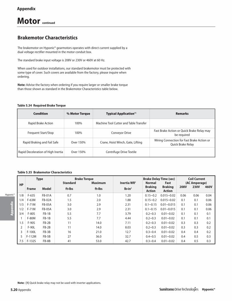
5.20 Appendix
App
endi
x
Hyponic®
Appendix
Hyponic®
Motor continued
Brakemotor Characteristics
Type Brake Torque Brake Delay Time (sec) Coil Current
HP Standard Maximum Inertia WR2 Normal Fast (AC Amperage)
Frame Model ft•lbs ft•lbs lb•in2 Braking Braking 208V 230V 460VAction Action
1/8 F-63S FB-01A 0.7 1.0 1.20 0.15~0.2 0.015~0.02 0.06 0.06 0.041/4 F-63M FB-02A 1.5 2.0 1.88 0.15~0.2 0.015~0.02 0.1 0.1 0.061/3 F-71M FB-05A 3.0 2.9 2.31 0.1~0.15 0.01~0.015 0.1 0.1 0.061/2 F-71M FB-05A 3.0 2.9 2.31 0.1~0.15 0.01~0.015 0.1 0.1 0.063/4 F-80S FB-1B 5.5 7.7 3.79 0.2~0.3 0.01~0.02 0.1 0.1 0.1
1 F-80M FB-1B 5.5 7.7 4.44 0.2~0.3 0.01~0.02 0.1 0.1 0.11.5 F-90S FB-2B 11 14.0 7.11 0.2~0.3 0.01~0.02 0.3 0.3 0.22 F-90L FB-2B 11 14.0 8.03 0.2~0.3 0.01~0.02 0.3 0.3 0.23 F-100L FB-3B 16 21.0 12.7 0.3~0.4 0.01~0.02 0.4 0.4 0.25 F-112M FB-5B 27 36.0 32.7 0.4~0.5 0.01~0.02 0.4 0.5 0.3
7.5 F-132S FB-8B 41 53.0 42.7 0.3~0.4 0.01~0.02 0.4 0.5 0.3
The brakemotor on Hyponic® gearmotors operates with direct current supplied by adual voltage rectifier mounted in the motor conduit box.
The standard brake input voltage is 208V or 230V or 460V at 60 Hz.
When used for outdoor installations, our standard brakemotor must be protected withsome type of cover. Such covers are available from the factory, please inquire whenordering.
Note: Advise the factory when ordering if you require larger or smaller brake torquethan those shown as standard in the Brakemotor Characteristics table below.
Table 5.35 Brakemotor Characteristics
Condition % Motor Torque Typical Application[1] Remarks
Rapid Brake Action 100% Machine Tool Cutter and Table Transfer
Frequent Start/Stop 100% Conveyor DriveFast Brake Action or Quick Brake Relay may
be required
Rapid Braking and Fail Safe Over 150% Crane, Hoist Winch, Gate, LiftingWiring Connection for Fast Brake Action or
Quick Brake Relay
Rapid Deceleration of High Inertia Over 150% Centrifuge Drive Textile
Table 5.34 Required Brake Torque
Note: [1] Quick brake relay may not be used with inverter applications.

Appendix 5.21
App
endi
x
Hyponic®
Appendix
Hyponic®
Motor continued
Brakemotor Standard Wiring Connection, Dual Voltage
Brake
M N
Furnished by SumitomoOLR
MC
Line 230V
Motor
T2T1 T3
Rectifier
21 3 4
VR
Brake
M N
Furnished by SumitomoOLR
MC
Line 460V
Motor
T2T1 T3
Rectifier
21 3 4
Motor Rectifier Brake
T1 T2 T3 1 2 3 4 M N
OLR
MC
Line 460V
VR
Furnished by Sumitomo
Brake
M N
Furnished by SumitomoOLR
MC
Line 230V
Motor
T2T1 T3
Rectifier
21 3 4
Figure 5.29 Normal Brake Action, Low Voltage
Figure 5.31 Fast Brake Action, Low Voltage
Figure 5.30 Normal Brake Action, High Voltage
Figure 5.32 Fast Brake Action, High Voltage
Models FB-01A through FB-8B
Table 5.36 Varistor Specifications TableMC: Electromagnetic RelayMCB: Magnetic Circuit BreakerOLR: Overload or Thermal RelayVR: Varistor (protective device)[1]
Note: [1] Refer to Varistor Specifications Table
Operating Voltage 230-460V 575V
Varistor Rated Voltage AC510V AC604VVaristor Voltage 820V 1000V
Rated Watt
FB01A, 02A Over 0.4W Over 0.4WFB-05A Over 0.4W Over 0.4WFB-1B Over 0.6W Over 0.4W
FB-2B, 3B Over 1.5W Over 0.6WFB-5B, 8B Over 1.5W Over 1.5W

Motor continued
5.22 Appendix
App
endi
x
Hyponic®
Appendix
Hyponic®
Brakemotor Standard Wiring Connection, Dual Voltage continued
FB Brake (1/8 to 7.5 HP) with Inverter
Motor
T2T1 T3
Rectifier
21 3 4
Brake
M N
MC
Line 460V
Furnished bySumitomo
InverterT2T1 T3
L2L1 L3
MCB
Motor
T2T1 T3
Rectifier
21 3 4
Brake
M N
MC
Line 230V
Furnished bySumitomo
InverterT2T1 T3
L2L1 L3
VR
MCB
Motor
T2T1 T3
Rectifier
21 3 4
Brake
M N
MC
Line 460V
Furnished bySumitomo
InverterT2T1 T3
L2L1 L3
MCB
Motor
T2T1 T3
Rectifier
21 3 4
Brake
M N
MC
Line 230V
Furnished bySumitomo
InverterT2T1 T3
L2L1 L3
MCB
Figure 5.35 Normal Brake Action, Low Voltage
Figure 5.37 Fast Brake Action, Low Voltage
Figure 5.36 Normal Brake Action, High Voltage
Figure 5.38 Fast Brake Action, High Voltage
MC: Electromagnetic RelayMCB: Magnetic Circuit BreakerVR: Varistor (protective device)[1]
Note: [1] Refer to Varistor Specifications Table on pg. 5.21
Quick Brake Relay Equipped Models
�����
��� �
�� ������
� �
��������
� �
�����
� �
���
��
��������
����� !�"�#��� ��$��
Figure 5.33 Quick Brake Action, Low Voltage (FB-05A, FB-1B, FB-2B, FB-3B)
����� �� ������ �����
��������
��
���
����
��
��������
�%��
����� !�"�#��� ��$��
Figure 5.34 Quick Brake Action, High Voltage (FB-2B, FB-3B, FB-5B, FB-8B)

Motor continued
Appendix 5.23
App
endi
x
Hyponic®
Appendix
Hyponic®
Brakemotor Assembly
Figure 5.39 Types FB-01A, 02A, 05A, 1B, 2B, 3B, 5B, 8B Assembly
a.
b.
c.
� � �� �� �� �� �� ��
� � � � �
Part No. Description1 Stationary Core2 Spacer3 Brake Lining4 Restraining Bolt5 Hub6 C-Type Retaining Ring7 Cover8 Fan (TEFC model only)9 Leaf Spring
10 Brake Shoe11 Armature12 Pressure Spring13 Solenoid Coil14 Ball Bearing15 Motor Shaft
Table 5.37a Type FB-01A, -02A, -05A
Part No. Description1 Stationary Core2 Brake Release Support3 Shifting Pin4 Spacer5 Gap Adjusting Sleeve6 Brake Release Lever7 Restraining Bolt8 Brake Lining9 Leaf Spring
10 Hub11 Retaining Ring12 Fan Cover13 Fan Set Screw14 Fan15 Fixed Plate16 Noise Shield17 Brake Shoe18 Armature Plate19 Pressure Spring20 Solenoid Coil21 Fan Side Motor Bearing22 Motor Shaft
Table 5.37b Type FB-1B, -2B, -3B
Part No. Description1 Stationary Core2 Brake Release Support3 Stud Bolt4 Gap Adjusting Sleeve5 Shifting Pin6 Brake Release Lever7 Spring Washer8 Nut9 Brake Lining
10 Hub11 Retaining Ring12 Fan Cover13 Fan Set Screw14 Fan15 Brake Shoe16 Armature Plate17 Pressure Spring18 Solenoid Coil19 Fan Side Motor Bearing20 Motor Shaft21 Bearing Cover
Table 5.37c Type FB-5B, -8B

5.24 Appendix
App
endi
x
Hyponic®
Appendix
Hyponic®
Motor continued
Rectifier Data
Table 5.38 Rectifier 25FW-4FB for Dual Voltage 230/460V Motors
Brake Part Number
Type UL CSA
FB-01A
EU884WW-01(EU986WW-01)[1]
ET476WW-01(DX527WW-01)[1]
FB-02A
FB-05A
FB-1B
FB-2B
FB-3B
FB-5B
FB-8B EU986WW-01 DX527WW01
Table 5.39 Rectifier 05F-5 for 575V CSA Motors
Brake Part
Type Number
FB-01A
DT574WW-01
FB-02A
FB-05A
FB-1B
FB-3B
FB-5B
FB-8B
Note: [1] ( ) indicate a usable alternative.
Appendix 5.25
App
endi
x
Hyponic®
Appendix
Hyponic®
Warranty
Sumitomo warrants that its Hyponic® Speed Reducers will deliver theircontinuous catalog ratings and up to 250% intermittent SHOCK LOADCAPACITY, provided they are properly installed, maintained and operat-ed within the limits of speed, torque or other load conditions underwhich they were sold. Sumitomo further states that Hyponic® SpeedReducers are warranted to be free from defects in material or workman-ship for a period of two years from the date of shipment. Sumitomoassumes no liability beyond product repair or replacement under thislimited warranty.
For construction purposes, be sure to obtain certified dimension sheetsor drawings. Although we take every precaution to include accuratedata in our catalog, we cannot guarantee such accuracy. If performanceguarantees are required, they should be obtained in writing from thefactory. Full consideration will be given to such requests when completedetails are given of the proposed installation.
5.26 Appendix
App
endi
x
Hyponic®
Appendix
Hyponic®
Notes
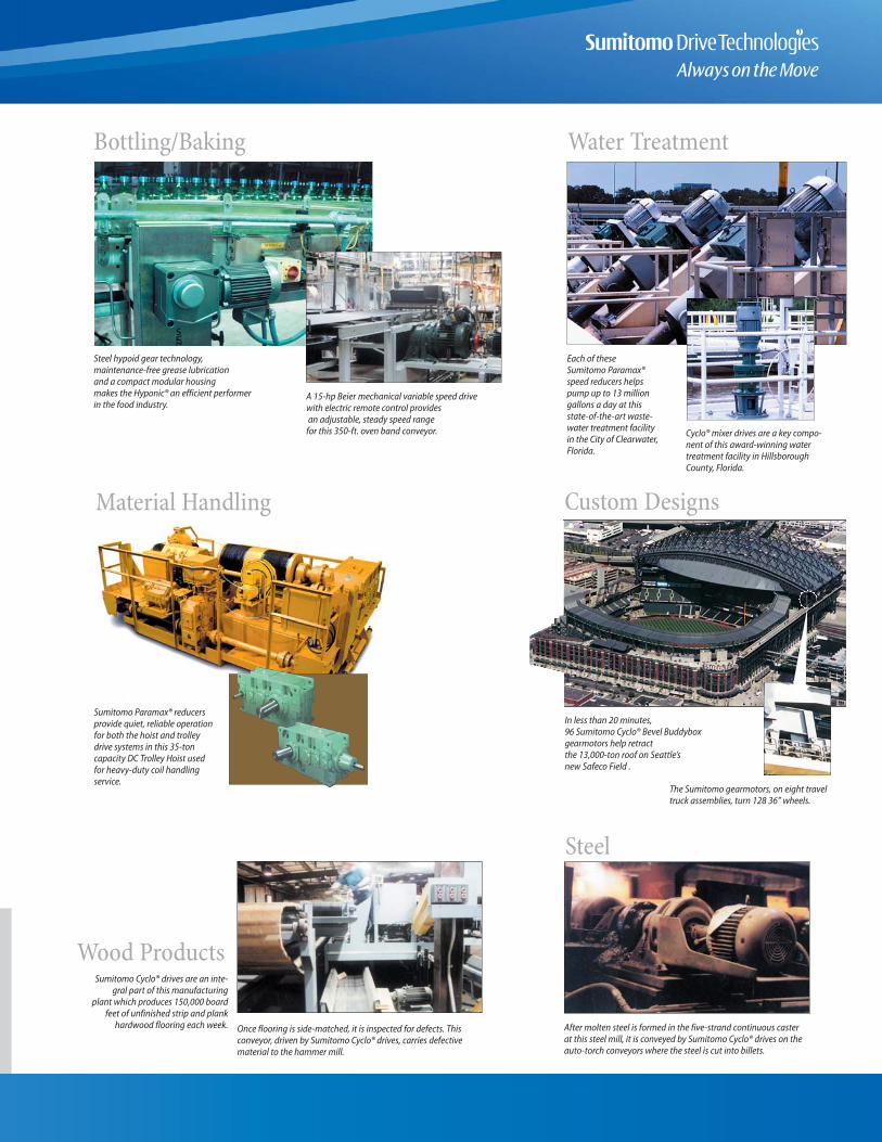
Steel hypoid gear technology, maintenance-free grease lubrication and a compact modular housing makes the Hyponic® an efficient performerin the food industry.
A 15-hp Beier mechanical variable speed drive with electric remote control providesan adjustable, steady speed range
for this 350-ft. oven band conveyor.
Bottling/Baking Water Treatment
Material Handling Custom Designs
Wood Products
Steel
Cyclo® mixer drives are a key compo-nent of this award-winning watertreatment facility in HillsboroughCounty, Florida.
Each of these Sumitomo Paramax® speed reducers helps pump up to 13 million gallons a day at this state-of-the-art waste-water treatment facility in the City of Clearwater,Florida.
In less than 20 minutes, 96 Sumitomo Cyclo® Bevel Buddybox gearmotors help retract the 13,000-ton roof on Seattle’s new Safeco Field .
The Sumitomo gearmotors, on eight traveltruck assemblies, turn 128 36” wheels.
Once flooring is side-matched, it is inspected for defects. Thisconveyor, driven by Sumitomo Cyclo® drives, carries defectivematerial to the hammer mill.
Sumitomo Cyclo® drives are an inte-gral part of this manufacturing
plant which produces 150,000 boardfeet of unfinished strip and plank
hardwood flooring each week. After molten steel is formed in the five-strand continuous caster at this steel mill, it is conveyed by Sumitomo Cyclo® drives on theauto-torch conveyors where the steel is cut into billets.
Sumitomo Paramax® reducersprovide quiet, reliable operationfor both the hoist and trolleydrive systems in this 35-toncapacity DC Trolley Hoist usedfor heavy-duty coil handlingservice.

Sumitomo Machinery Corporation of AmericaHeadquarters & Manufacturing
4200 Holland BoulevardChesapeake, VA 23323Tel: 757-485-3355 • Fax: 757-485-3075
www.sumitomodrive.comE-mail: [email protected]
World Headquarters
JapanSumitomo Heavy Industries, Ltd.Power Transmission & Controls Group5-9-11, KITA-Shinagawa, Shinagawa-KuTokyo 141-8686 JapanTel: 011-813-5488-8363 • Fax: 011-813-5488-8365
For Worldwide contact information:www.sumitomodrive.com
U.S. Sales and SupportMid-WestSumitomo Machinery Corporation of America175 West Lake DriveGlendale Heights, IL 60139Tel: 630-752-0200 • Fax: 630-752-0208
WestSumitomo Machinery Corporation of America2375 Railroad StreetCorona, CA 92880-5411Tel: 951-340-4100 • Fax: 951-340-4108
SouthwestSumitomo Machinery Corporation of America1420 Halsey Way #130Carrollton, TX 75007Tel: 972-323-9600 • Fax: 972-323-9308
CanadaToronto (East)SM-Cyclo of Canada, Ltd.870 Equestrian CourtOakville, Ontario, Canada L6L 6L7Tel: 905-469-1050 • Fax: 905-469-1055
Vancouver (West)SM-Cyclo of Canada, Ltd.740 Chester Road, Annacis Island, DeltaB.C., Canada V3M 6J1Tel: 604-525-5403 • Fax: 604-525-0879
MontrealSM-Cyclo of Canada, Ltd.226 Migneron StreetSt. Laurent, Quebec, Canada H4T 1Y7Tel: 514-340-1300 • Fax: 514-340-1343
MexicoMonterreySM-Cyclo de Mexico, S.A. de C.V.Calle “C” No. 506AParque Industrial AlmacentroApodaca, N.L., Mexico 66600Tel: 011-52-81-8144-5130 • Fax: 011-52-81-8369-3699
Mexico CitySM-Cyclo de Mexico S.A. de C.V.Privada Ceylan No. 59-B BisColonia Industrial VallejoDelegacion Azcapotzalco, DF Mexico 02300Tel: 011-52-55-5368-7172 • Fax: 011-52-55-5368-6699
South AmericaBrazilSM-Cyclo Redutores do Brasil Ltda.Av. Fagundes Filho, 191Ed. Houston Office Center–c j. H123CEP: 04304-010–São Paulo, BrazilTel: 011-55-11-5585-3600 • Fax: 011-55-11-5585-9990
ChileSM-Cyclo de Chile Ltda.San Pablo 3507Comuna de Quinta Normal - Santiago, ChileTel: 011-562-786-6963 • Fax: 011-562-786-6964
ArgentinaSM-Cyclo de Argentina SAManuel Montes de Oca 6719B1606 BMG, MunroBuenos Aires, ArgentinaTel: 011-54-11-4765-5332 • Fax: 011-54-11-4765-5517
EuropeAustria
Belgium
France
Germany
Italy
Netherlands
Spain
Sweden
Switzerland
AsiaChina
Hong Kong
Indonesia
Korea
Malaysia
Philippines
Taiwan
Thailand
Other Locations Australia
India
New Zealand
South Africa
WORLDWIDE LOCATIONS