Hyperspectral Imaging for Erosion Detection in Wind Turbine Blades … · 2017-07-05 ·...
2
Hyperspectral Imaging for Erosion Detection in Wind Turbine Blades Andrew Young a , Andrew Kay b , Stephen Marshall a , Ralph Torr b , and Alison Gray c a Department of Electronic and Electrical Engineering, University of Strathclyde b Offshore Renewable Energy Catapult, Glasgow, UK c Department of Mathematics and Statistics, University of Strathclyde I. Introduction Inspection of wind turbine blades is required to identify any defects or failures and decide on any remedial actions, e.g. blade repair or replacement. Traditionally, inspections have been performed by rope access technicians who visually inspect the blades and record damage using standard photographic equipment. Recent developments have seen an increase in popularity in the use of remote-based inspection techniques using ground-mounted cameras and cameras installed on Remotely Operated Aerial Vehicles, more commonly referred to as drones. While these methods remove the need for human access to the blades, imaging is performed remotely and does not always provide adequate image quality using standard high definition cameras. As a result, there is a growing interest in imaging techniques based on other regions of the electromagnetic spectrum. Laboratory and field trials are required to examine this potential properly and understand which frequencies can be most effectively applied to imaging blades. This paper demonstrates a Hyperspectral imaging technique for imaging surface defects on a section of wind turbine blade in a laboratory. II. Wind Turbine Blades The materials of blades must be robust and rigid, yet as light as possible to satisfy the blade design criteria and to minimise both the weight-induced fatigue loads and the loads on the tower and foun- dations. The materials of contemporary blades are usually fibre-reinforced composites which provide low weight, high strength and stiffness and optimal performance in fatigue. The majority of blades are made of glass fibre/epoxy, glass fibre/polyester or carbon fibre/epoxy composites [1]. Blades are designed to last for a minimum of 20 years, during which time they will be subjected to varying weather patterns and wind loads. Thus, they should be designed to withstand different types of damage, e.g. erosion, and damage due to extreme conditions [2]. Damage can occur in many ways. It is important to identify different damage types correctly so that appropriate remedial actions can be performed. Leading edge erosion is one of the biggest issues during the operations and maintenance phase of wind farms, particularly offshore. It occurs as a result of different interactions between the blades rotating at high speeds and the environment, e.g. icing, high winds and impact with rain, hailstones, dust and other atmospheric contaminants [3]. Figure 1: Leading Edge Erosion III. Methodology A. Equipment Set-up The initial stage of the process was to set-up the hyperspectral camera. In the lab, it is possible to image the blade at a distance that would not be safe to operate at in practice without risking damage to the system or blade. Therefore a distance of 1.5 metres was selected to provide adequate resolution of the blade from the camera but yet should still be feasible for use in the field. B. Initial Imaging The blade and camera were positioned, and the speed was selected so as to provide square pixels in the image. Prior to hyperspectral imaging, some images were taken with an RGB camera to provide details of any defects already present within the blade. Following this, the first image was taken using the hyperspectral camera and any pre-existing defects were highlighted in this new hyperspectral image (Figure 2). For this example, the 1200nm band of the image was used. This band was selected as it provided the most contrast for each of the damage types.
Transcript of Hyperspectral Imaging for Erosion Detection in Wind Turbine Blades … · 2017-07-05 ·...
Hyperspectral Imaging for Erosion Detectionin Wind Turbine Blades
Andrew Younga, Andrew Kayb, Stephen Marshalla, Ralph Torrb, and Alison Grayc
aDepartment of Electronic and Electrical Engineering, University of StrathclydebOffshore Renewable Energy Catapult, Glasgow, UK
cDepartment of Mathematics and Statistics, University of Strathclyde
I. Introduction
Inspection of wind turbine blades is required toidentify any defects or failures and decide on anyremedial actions, e.g. blade repair or replacement.Traditionally, inspections have been performedby rope access technicians who visually inspectthe blades and record damage using standardphotographic equipment.
Recent developments have seen an increase inpopularity in the use of remote-based inspectiontechniques using ground-mounted cameras andcameras installed on Remotely Operated AerialVehicles, more commonly referred to as drones.While these methods remove the need for humanaccess to the blades, imaging is performedremotely and does not always provide adequateimage quality using standard high definitioncameras. As a result, there is a growing interestin imaging techniques based on other regions ofthe electromagnetic spectrum. Laboratory andfield trials are required to examine this potentialproperly and understand which frequencies can bemost effectively applied to imaging blades.
This paper demonstrates a Hyperspectralimaging technique for imaging surface defects ona section of wind turbine blade in a laboratory.
II. Wind Turbine Blades
The materials of blades must be robust and rigid,yet as light as possible to satisfy the blade designcriteria and to minimise both the weight-inducedfatigue loads and the loads on the tower and foun-dations. The materials of contemporary blades areusually fibre-reinforced composites which providelow weight, high strength and stiffness and optimalperformance in fatigue. The majority of blades aremade of glass fibre/epoxy, glass fibre/polyester orcarbon fibre/epoxy composites [1].
Blades are designed to last for a minimum of 20years, during which time they will be subjected tovarying weather patterns and wind loads. Thus,they should be designed to withstand differenttypes of damage, e.g. erosion, and damage due toextreme conditions [2].
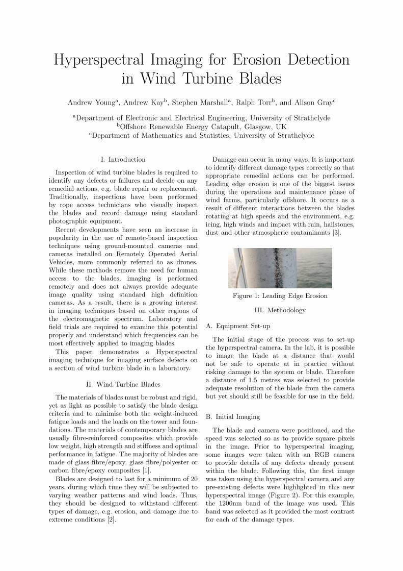
Damage can occur in many ways. It is importantto identify different damage types correctly so thatappropriate remedial actions can be performed.Leading edge erosion is one of the biggest issuesduring the operations and maintenance phase ofwind farms, particularly offshore. It occurs as aresult of different interactions between the bladesrotating at high speeds and the environment, e.g.icing, high winds and impact with rain, hailstones,dust and other atmospheric contaminants [3].
Figure 1: Leading Edge Erosion
III. Methodology
A. Equipment Set-up
The initial stage of the process was to set-upthe hyperspectral camera. In the lab, it is possibleto image the blade at a distance that wouldnot be safe to operate at in practice withoutrisking damage to the system or blade. Thereforea distance of 1.5 metres was selected to provideadequate resolution of the blade from the camerabut yet should still be feasible for use in the field.
B. Initial Imaging
The blade and camera were positioned, and thespeed was selected so as to provide square pixelsin the image. Prior to hyperspectral imaging,some images were taken with an RGB camerato provide details of any defects already presentwithin the blade. Following this, the first imagewas taken using the hyperspectral camera and anypre-existing defects were highlighted in this newhyperspectral image (Figure 2). For this example,the 1200nm band of the image was used. Thisband was selected as it provided the most contrastfor each of the damage types.

Figure 2: Top & Bottom: RGB images of defects.Middle: Initial HS image (1200nm band).
C. Introduction of Damage Types
Having completed the initial study, somerealistic defects were added to the blade (Figure3). Those selected were of the type that would bepresent in a turbine operating in the real worldover several years [3]. Each of these damage typesprovides a different challenge for detection. A newhyperspectral image was then taken.
(a) Light erosion (b) Pink laminate (c) Grey laminate
Figure 3: Damage types
IV. Results
A. Band Selection
Figure 4: Average contrast between eroded andnot-eroded surface pixels for every wavelength
As the hyperspectral camera outputs 256 bandsbetween 950nm and 1800nm, before any furtherprocessing, it was necessary to determine theoptimal bands to use. This was done by manuallyselecting a region of eroded and non-eroded surface.For each band, the contrast, i.e. the differencebetween the eroded and non-eroded surfaceintensity, was calculated, and an average contrastwas obtained. It was found that the bands between1182nm and 1233nm were the best bands to use forthe analysis (Figure 4), giving the most contrast.
B. Classification
Having determined an appropriate band it wasthen possible to create a single image from eachhyperspectral image (Figure 5a). This was createdby first selecting the leading edge of the bladeand then 10 pixels to either side of this edge, andthe rest of the data were discarded. The imageshows the first two damage types in a section ofthe blade, from right to left. However, the thirdis not quite visible.
C. Image Flattening
To try to improve the contrast of the images,the surface of the wind turbine blade was assumedto have the geometry of a circular pipe. Thisprofile was then subtracted to flatten the image.This increased the contrast in the image, and theresults are shown in Figure 5b.
(a) RGB image created from SWIR hyperspectral image
(b) Image after surface subtraction
Figure 5
V. Conclusions
Figure 6: Image taken with Nikon D5500 cameraHaving compared the processed hyperspectral
image results (Figure 5) to the high-resolutioncamera (Figure 6), it is clear that there is moredetail shown from the hyperspectral images,specifically the depth of the erosion indicated bythe intensity of the image. However, for field appli-cations such as condition monitoring, this addedinformation is not necessarily useful. Currently, thedamage is classified into four main categories usingstandard imaging techniques. As it is possible todo this therefore for this application, hyperspectralimagery may not be necessary. However, there aremany other applications for the technology in thisfield. Here we illustrate some of its potentials.
References[1] M. Jureczko, M. Pawlak, and A. Mężyk, “Optimisation
of wind turbine blades,” Journal of Materials ProcessingTechnology 167(2), pp. 463–471, 2005.
[2] P. Brøndsted, H. Lilholt, and A. Lystrup, “Compositematerials for wind power turbine blades,” Annu. Rev.Mater. Res. 35, pp. 505–538, 2005.
[3] D. Rivkin and L. Silk, Wind Turbine Operations, Main-tenance, Diagnosis, and Repair, Jones & Bartlett Pub-lishers, 2012.