HyperSecureLink V5.0x User Guide - · PDF file(Note: For the USB Adaptor, please refer to the...
16
HyperSecureLink V5.0x User Guide Note: This software works with the LS-30 Version (05.xx or later) 1, Hardware Installation: 1-1, Connection Diagram for USB or RS-232 Computer Interface COM1 cable USB or RS-232 Adaptor HyperSecureLink Software (Note: For the USB Adaptor, please refer to the USB-3 USB Adapter User Guide in the CD ROM.) 1-2, Connection Diagram for Internet Remote Access COM1 Cable Ethernet Adaptor Router (Note: For the Ethernet Adaptor, please refer to the Ethernet Adaptor User Guide in the CD ROM.) 1-3, Connection Diagram for Data Communication Module (Dialup Modem) COM1 Cable Data Communication Module (Note: For the Data Communication Module, please refer to the DM-30 Data Communication Module User Guide in the CD ROM.) Internet To LS-30 COM1 HyperSecureLink or CMS polling software To PC USB or COM Port To LS-30 COM1 PSTN To LS-30 COM1 HyperSecureLink or CMS polling software Tel Line Tel. line
Transcript of HyperSecureLink V5.0x User Guide - · PDF file(Note: For the USB Adaptor, please refer to the...

HyperSecureLink V5.0x User Guide
Note: This software works with the LS-30 Version (05.xx or later) 1, Hardware Installation:
1-1, Connection Diagram for USB or RS-232 Computer Interface
COM1 cable USB or RS-232 Adaptor HyperSecureLink Software
(Note: For the USB Adaptor, please refer to the USB-3 USB Adapter User Guide in the CD ROM.)
1-2, Connection Diagram for Internet Remote Access
COM1 Cable Ethernet Adaptor Router
(Note: For the Ethernet Adaptor, please refer to the Ethernet Adaptor User Guide in the CD ROM.)
1-3, Connection Diagram for Data Communication Module (Dialup Modem)
COM1 Cable Data Communication Module
(Note: For the Data Communication Module, please refer to the DM-30 Data Communication Module User Guide in the CD ROM.)
Internet
To LS-30 COM1
HyperSecureLink or CMS polling software
To PC USB or COM PortTo LS-30
COM1
PSTN
To LS-30 COM1
HyperSecureLink or CMS polling software
Tel Line
Tel. line

Important Notice,
Before running the HyperSecureLink V5.0x, please check the following settings on the Base Unit,
1). Master Mode\ Set RS232 Control\ RS-232=ON. 2). If the LS-30 RS232 Control - Need Password then a valid password should be set in “System &
Link” and then click the submit button. Different password has different access right to the system. Please refer to the Appendix A.
RS-232 control with PSW needed/ unneeded and their access right on LS-30

2, Software Installation: Copy the whole "HyperSecureLink V5.0x" directory from CD ROM to the Disk “C”. Note: The whole program size is about 100MB, please ensure the Disk ” C” has enough free space for the program.
For the user with Windows XP/Vista or later version OS 1,Open the directory of HyperSecureLink V5.0x 2, Double click the RUN.BAT
For the user with other OS. 1, Open the directory of HyperSecureLink V5.0x 2, Open the sub-directory of DB.
3, Remove the READ ONLY Attribute of the following 4 files: DB.JDS, db_LOGA_0000000000, db_LOGA_ANCHOR, db_temp.jds 4, Open the directory of HyperSecureLink V5.0x 5, Double click the RUN.BAT
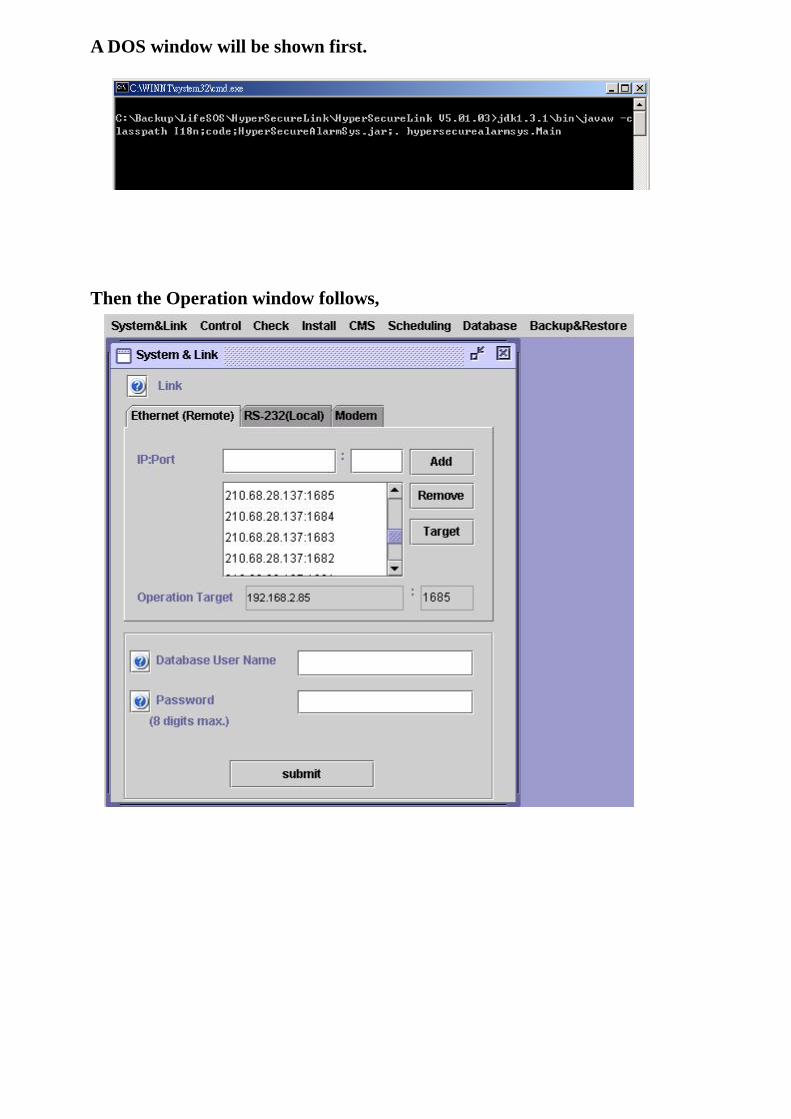
A DOS window will be shown first.
Then the Operation window follows,

3, Select Link 3.1 Using RS-232 interface to access the LS-30 ( RS-232 Adaptor or USB-3 Adaptor is needed ).
Select RS-232 (Local) .
The software will scan the RS-232 ports that are available in your PC. Select the correct one to use.

3.2 Using Ethernet interface to access the LS-30 (Ethernet adaptor is needed and the router should be set in advance. Please refer to the Ethernet Adaptor User Guide). 1, Select Ethernet (Remote) . 2, Enter the IP address or domain name and the Port number of the Ethernet Adaptor that connects to
the LS-30 Base Unit and click Add.
3, Mark the IP address and click the Target to assign this address as the operation target.
IP address and port number Domain Name and port number

You can use any word process software to save the frequently use IP address or domain name into the file of “ipAddr.txt” as below then the program will load these address automatically when you run the program.
3.3 Use Data Communication Module (Dialup Modem) to access the LS-30. (Please refer to the Data
Communication Module User Guide) 1, Select Modem . 2, Select the dial signaling (Tone/ Pulse) of the telephone system that connects to your computer. 3, Select the correct Modem COM port on your computer. 4, Enter the telephone number of the Data Communication Module that connects to the LS-30 Base
Unit and click Dial.
Note: you can turn on the speaker on your computer to monitor the connection process. 5, At the end of your operation you should click the Disconnect button to disconnect the
communication link.
This example shows that two IP addresses: 210.68.28.137:1700 and scientech.dyndns.org:1680
will be listed in the IP:Port box and the current Operation Target is scientech.dyndns.org:1680
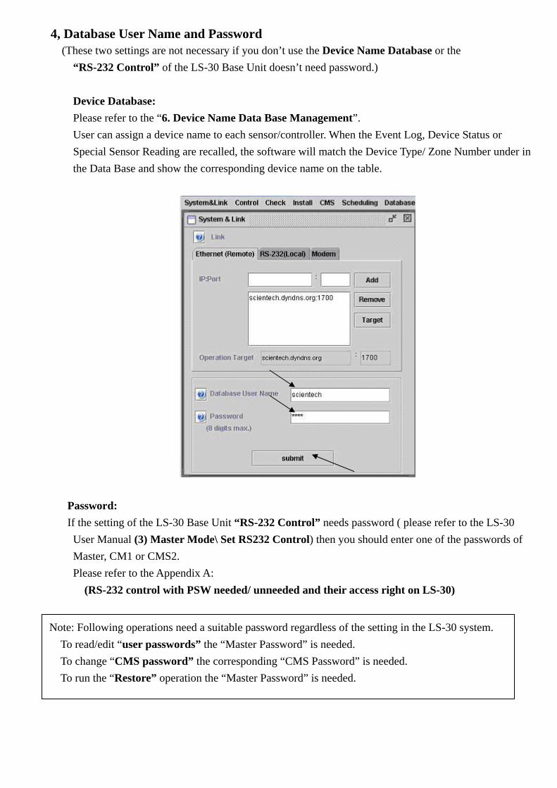
4, Database User Name and Password (These two settings are not necessary if you don’t use the Device Name Database or the
“RS-232 Control” of the LS-30 Base Unit doesn’t need password.) Device Database: Please refer to the “6. Device Name Data Base Management”. User can assign a device name to each sensor/controller. When the Event Log, Device Status or Special Sensor Reading are recalled, the software will match the Device Type/ Zone Number under in the Data Base and show the corresponding device name on the table.
Password: If the setting of the LS-30 Base Unit “RS-232 Control” needs password ( please refer to the LS-30
User Manual (3) Master Mode\ Set RS232 Control) then you should enter one of the passwords of Master, CM1 or CMS2.
Please refer to the Appendix A: (RS-232 control with PSW needed/ unneeded and their access right on LS-30)
Note: Following operations need a suitable password regardless of the setting in the LS-30 system. To read/edit “user passwords” the “Master Password” is needed. To change “CMS password” the corresponding “CMS Password” is needed. To run the “Restore” operation the “Master Password” is needed.

5. Operation Select the function from the Menus bar.
* Click down arrow to select the command.
* Update the setting of the LS-30 Base Unit by clicking .
* Read the status from the LS-30 Base Unit by clicking .
* Checking the function and the operation of the command by clicking .
Menus bar
Down arrow
What’s the meaning of
this operation?
How to operate this
function?
This is the answer.
Update setting
Read status
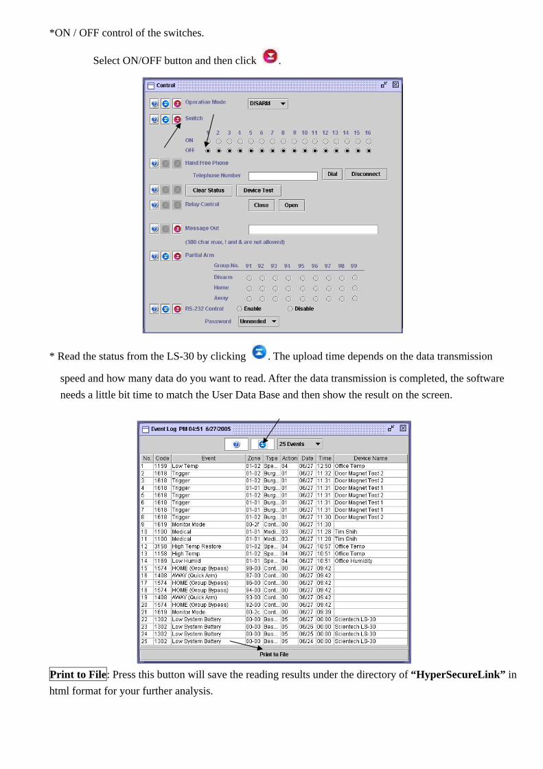
*ON / OFF control of the switches.
Select ON/OFF button and then click .
* Read the status from the LS-30 by clicking . The upload time depends on the data transmission
speed and how many data do you want to read. After the data transmission is completed, the software needs a little bit time to match the User Data Base and then show the result on the screen.
Print to File: Press this button will save the reading results under the directory of “HyperSecureLink” in html format for your further analysis.

* Entering figures and click to update the data/ parameters in the LS-30 Base Unit.
* Enroll Device Procedure:
1), Press Enroll Device , select the device type. 2), Press the Press to Start Code Learning button. 3), Press the test button or trigger the device that you want to learn in 60 seconds. 4), When the Base Unit receives the RF signal from the device, the default device settings will be listed on
the display and the system will assign a zone number to this device automatically. 5), If the assignment is ok for you, press the OK button. Otherwise press Change Setting and
select proper settings then press the Edit Settings then Press to Change .
All the settings are ok! You want to change settings.

* Using command button to send commands to the LS-30 Base Unit
* Send messages to show on the Base Unit LCD display.
Key in the message then click to send the words to the LS-30 Base Unit.
After receiving the message, the LS-30 will issue “Message In” voice in every 5 minutes to alert the user and user can read the message by key in Hot Key “5”. To stop the “Message In” alert by key in the Hot Key “C” (Clear command.)

6. Device Name Data Base Management User can assign a device name to each device and zone. When the Event Log, Device Status or Special Sensor Reading are read, the software will match the Device Type, Zone Number and the User Name in the Data Base and show the corresponding device name on the table. For example, if you installed two systems, one in your company (name: scientech) and the other one in your home (name: John), and they both have the Door Magnet Burglar Sensor at Zone 01-01.
The device name of the Burglar Sensor 01-01 in the office is “Front Door”. The device name of the Burglar Sensor 01-01 at your home is “Living Room”.
The software uses different User Name to identify the two different devices although they have the identical Device Type and Zone Number.
* Creating the Device Name Data Base:
* Check Device Name List:
Add Device Name to the Data Base 1, Enter Group Number. 2, Enter Unit Number. 3, Select Device Type. 4, Enter User Name. 5, Enter Device Name. 6, Press “Add”.
Refresh the Data Base each time after you added a device
Press these title buttons, the sequence of the components in the Data Base will be rearranged.
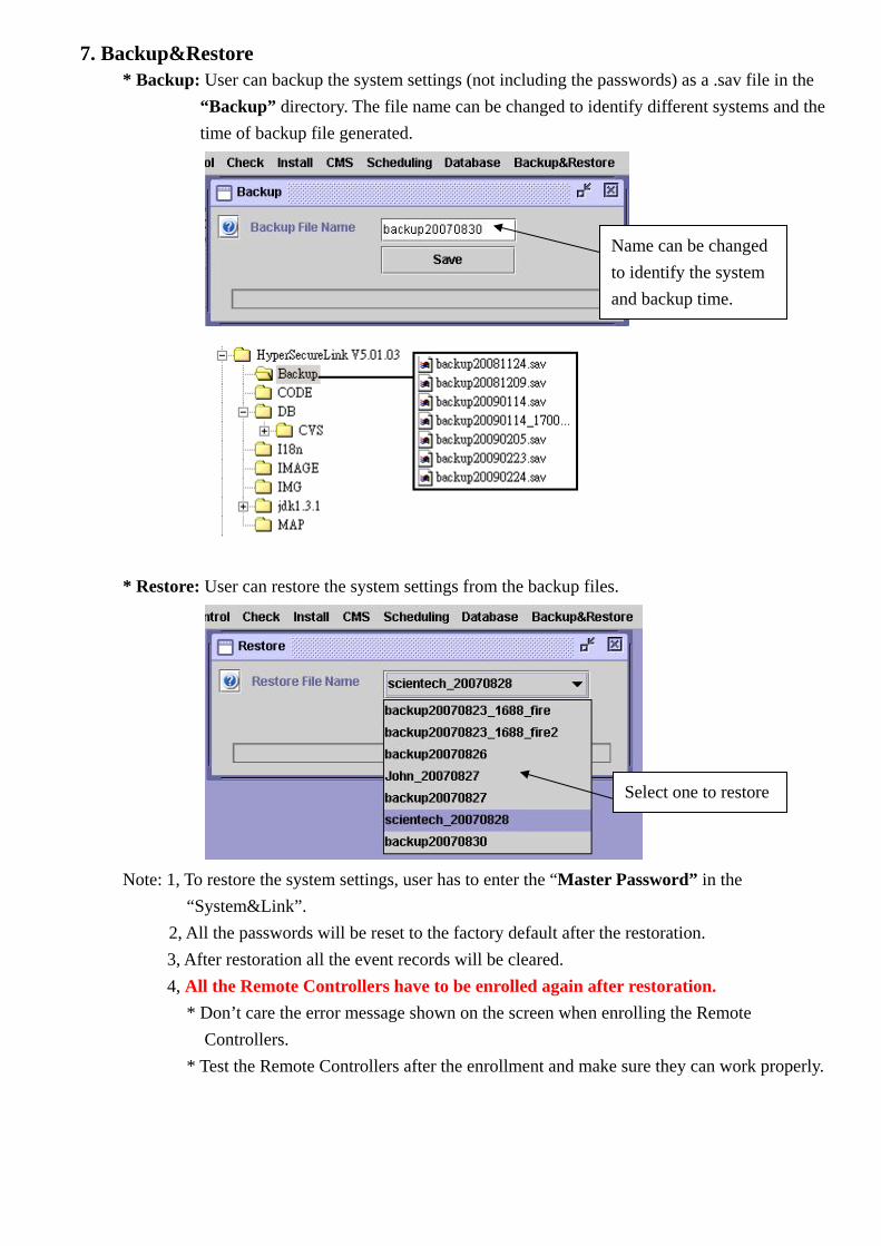
7. Backup&Restore * Backup: User can backup the system settings (not including the passwords) as a .sav file in the
“Backup” directory. The file name can be changed to identify different systems and the time of backup file generated.
* Restore: User can restore the system settings from the backup files.
Note: 1, To restore the system settings, user has to enter the “Master Password” in the
“System&Link”. 2, All the passwords will be reset to the factory default after the restoration.
3, After restoration all the event records will be cleared. 4, All the Remote Controllers have to be enrolled again after restoration.
* Don’t care the error message shown on the screen when enrolling the Remote Controllers.
* Test the Remote Controllers after the enrollment and make sure they can work properly.
Name can be changed to identify the system and backup time.
Select one to restore

Appendix A: RS-232 control with PSW needed/ unneeded and their access right on LS-30
G/G: Read Good/ Set Good. G/F: Read Good/ Set Fail. F/G: Read Fail/ Set Good F/F: Read Fail/ Set Fail
RS-232 Control PSW needed PSW unneeded Function PSW using User/Installer Master CMS1 CMS2 Master no
Control Operation Mode G/G G/F G/F X-10 G/G G/F G/F Hand free Dial G F F Hand free Disconnect G F F Clear Status G F F Device Test G F F Relay Control Close G F F Relay Control Open G F F Message Out G G G Partial Arm G/G G/F G/F RS-232 Control/ PSW G/G G/F G/F Check Event Log G G G Device Status G G G Telephone Num G G G Date/Time G G G
G O O D
User Password G/G F/F F/F F/F Door Bell G/G G/F G/F Voice Play back G G G Special Sensor Reading G G G Install Timer Date/time Adjust G/G G/F G/F Entry Delay G/G G/F G/F Exit Delay G/G G/F G/F Inner Siren G/F G/F G/F Relay Action Time G/F G/F G/F Sensor Supv. Time G/F G/F G/F Remote Siren Time G/F G/F G/F Telephone Number G/F G/F G/F Dial Mode G/F G/F G/F Auto Answer Ring Count G/F G/F G/F Line Cut Detection G/F G/F G/F Cease Dialing Mode G/F G/F G/F Telephone Ringer G/F G/F G/F Dial Tone Check G/F G/F G/F Sound Record F F F Play back G G G Entry delay beep G/F G/F G/F Alarm Warning G/F G/F G/F Device Enroll Device F F F Change Device Settings G/F G/F G/F Delete Device F F F Remote Registration F F F Wire Sensor Input G/F G/F G/F Siren Inner Siren G/F G/F G/F Mode Change Chirp G/F G/F G/F Tamper Siren In Disarm G/F G/F G/F Set Remote Siren G/F G/F G/F Siren/Relay Test G F F Switch
F A I L
G O O D
G O O D

Switch Type G/F G/F G/F X-10 House Code G/G G/F G/F Switch Registration G/F G/F G/F Misc. RF Jamming Warning G/F G/F G/F Rom Version G G G Reset to Factory Default F F F Emergency Button
Assignment G/F G/F G/F
Inactivity Function G/F G/F G/F #16 SW Control G/F G/F G/F Modem Ring Count G/F G/F G/F GSM Number G/F G/F G/F CMS CMS1 CMS phone/Account/GSM G/F F/F
G O O D
G O O D
Change Password F F F F Mode Change Report G/F G/F Auto Link Check Period G/F G/F Loop back Test F F 2-way Audio G/F G/F DTMF data length G/F G/F CMS Report G/F G/F Ethernet Report G/F G/F GPRS Report G/F G/F IP Report Format G/F
G O O D
G/F CMS2 CMS phone/Account/GSM G/F F/F
G O O D
G O O D
Change Password F F F F Mode Change Report G/F G/F Auto Link Check Period G/F G/F Loop back Test F F 2-way Audio G/F G/F DTMF data length G/F G/F
G O O D
Schedule X-10 Switches G/G F/F F/F Auto Operation G/G F/F F/F Switch Scene G/G F/F F/F Operation Scene G/G F/F F/F
G O O D
G O O D
Backup & Restore
Backup G G G G G Restore
F A I L
G F F G F