Hypermesh Geometry
13
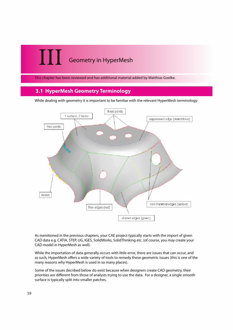
59 3.1 HyperMesh Geometry Terminology While dealing with geometry it is important to be familiar with the relevant HyperMesh terminology: As menitioned in the previous chapters, your CAE project typically starts with the import of given CAD data e.g. CATIA, STEP, UG, IGES, SolidWorks, SolidThinking etc. (of course, you may create your CAD model in HyperMesh as well). While the importation of data generally occurs with little error, there are issues that can occur, and as such, HyperMesh offers a wide variety of tools to remedy these geometric issues (this is one of the many reasons why HyperMesh is used in so many places). Some of the issues decribed below do exist because when designers create CAD geometry, their priorities are different from those of analysts trying to use the data. For a designer, a single smooth surface is typically split into smaller patches. III Geometry in HyperMesh 3.1 HyperMesh Geometry Terminology This chapter has been reviewed and has additional material added by Matthias Goelke.
description
Hypermesh
Transcript of Hypermesh Geometry
59
3.1 HyperMesh Geometry Terminology
While dealing with geometry it is important to be familiar with the relevant HyperMesh terminology:
As menitioned in the previous chapters, your CAE project typically starts with the import of given
CAD data e.g. CATIA, STEP, UG, IGES, SolidWorks, SolidThinking etc. (of course, you may create your
CAD model in HyperMesh as well).
While the importation of data generally occurs with little error, there are issues that can occur, and
as such, HyperMesh o!ers a wide variety of tools to remedy these geometric issues (this is one of the
many reasons why HyperMesh is used in so many places).
Some of the issues decribed below do exist because when designers create CAD geometry, their
priorities are di!erent from those of analysts trying to use the data. For a designer, a single smooth
surface is typically split into smaller patches.
III Geometry in HyperMesh
3.1 HyperMesh Geometry Terminology
This chapter has been reviewed and has additional material added by Matthias Goelke.
60
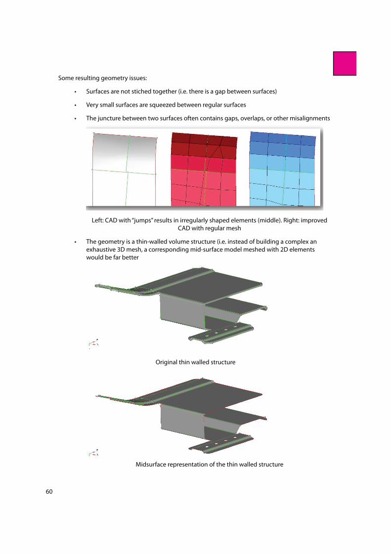
Some resulting geometry issues:
Surfaces are not stiched together (i.e. there is a gap between surfaces)
Very small surfaces are squeezed between regular surfaces
The juncture between two surfaces often contains gaps, overlaps, or other misalignments
Left: CAD with “jumps” results in irregularly shaped elements (middle). Right: improved
CAD with regular mesh
The geometry is a thin-walled volume structure (i.e. instead of building a complex an
exhaustive 3D mesh, a corresponding mid-surface model meshed with 2D elements
would be far better
Original thin walled structure
Midsurface representation of the thin walled structure

61
Surfaces penetrate each other (such as at a t-connection) but don‘t “feel“ each other
Original Geometry
Geometry "xed so that there is proper connectivity
Geometry is much too detailed (e.g. tiny "llets which are not needed for the analysis)
Original geomery, note the small "llets
Simpli"ed geometry where small "llets are replaced by a sharp edge
And many others ...

62
3.2 Geometry Cleanup
All of the issues de"ned inthe previous section typically demand what is called Geometry Cleanup.
Topology Repair: Strategy
Below is a general strategy that can be followed to perform the topology repair. This is a generalized
strategy which may need to be changed to suit the needs of your model, but it provides a good
starting point to perform the topology repair.
1. Understand the size and scale of the model
With models that represent everything from full size ships to microscopic electronic
parts all residing in a graphics area on a computer monitor, it is often di#cult to
understand the overall scope of the model. It is critical to get an idea of the overall
size of the model and determine a global element size that will be applied to the
eventual mesh.
2. Set a cleanup tolerance based upon the previously determined global element size.
With the element size established, a cleanup tolerance can now be set. The cleanup
tolerance speci"es the largest gap size to be closed by the topology functions. This
value should never exceed 15-20% of the global element size. Values beyond this
limit can introduce distortion into the mesh.
3. Use topology display tools to determine what needs to be "xed. For instance, to display
the topology of 2D geometry set the selector to “By 2D Topo”
Visualization mode: By Comp (which takes the color of the component)
3.2 Geometry Cleanup
Topology Repair: Strategy

63
Visualization mode: By 2D Topo
Visualization mode: Mixed which takes the component color and add topology
information
4. Find duplicate surfaces and delete them.
To delete duplicate surfaces, from the menu bar select Geometry > Defeature >
Duplicates.
5. Use equivalence to combine as many free edge pairs as possible.
Visually verify no surfaces were collapsed with this function.
6. Use toggle to combine any remaining edges.
Use replace if more control is needed.
7. Use !ller surface to "ll in any missing surfaces.
8. The equivalence, toggle, and !ller surface can be accessed within the Quick Edit panel.
To access the Quick Edit panel, from the menu bar select Geometry > Quick Edit.
Topology Repair: Tools and Panels
The perimeter of a surface is de"ned by edges. There are four types of surface edges:
1. Free edges
2. Shared edges
3. Suppressed edges
4. Non-manifold edges
Topology Repair: Tools and Panels

64
Surface edges are di!erent from lines and are sometimes handled di!erently for certain HyperMesh
operations. The connectivity of surface edges constitutes the geometric topology. Below the four
types of surface edges which represents the geometric topology is described (Note: the shown
model is displayed via the “2DTopo” mode in HyperMesh).
Free Edges
A free edge is an edge that is owned by only one surface. Free edges are colored red by default.
On a clean 2-D model consisting of surfaces, free edges appear only along the outer perimeter of the
part and around any interior holes. Note: Free edges that appear between two adjacent surfaces
indicate the existence of a gap between the two surfaces. The automesher will leave a gap in
the mesh wherever there is a gap between two surfaces.
Shared Edges
A shared edge is an edge that is owned, or shared, by two adjacent surfaces. Shared edges are
colored green by default.
When the edge between two surfaces is a shared edge (this is what you typically want to have), there
is no gap or overlap between the two surfaces - they are geometrically continuous. The automesher
always places seed nodes along the length a shared edge and will produce a continuous mesh
without any gaps along that edge. The automesher will not construct any individual elements that
cross over a shared edge.
Suppressed Edges
A suppressed edge is shared by two surfaces but it is ignored by the automesher. Suppressed edges
are colored blue by default.
Like a shared edge, a suppressed edge indicates geometric continuity between two surfaces but,
unlike a shared edge, the automesher will mesh across a suppressed edge as if were not even
there. The automesher does not place seed nodes along the length of a suppressed edge and,
consequently, individual elements will span across it. By suppressing undesirable edges you are
e!ectively combining surfaces into larger logical meshable regions.
Non-manifold Edges
A non-manifold edge is owned by three or more surfaces. Non-manifold edges are colored yellow
by default.
They typically occur at “T” intersections between surfaces or when 2 or more duplicate surfaces exist.
The automesher always places seed nodes along their length and will produce a continuous mesh
65
without any gaps along that edge. The automesher will not construct any individual elements that
cross over a T-joint edge. These edges cannot be suppressed.
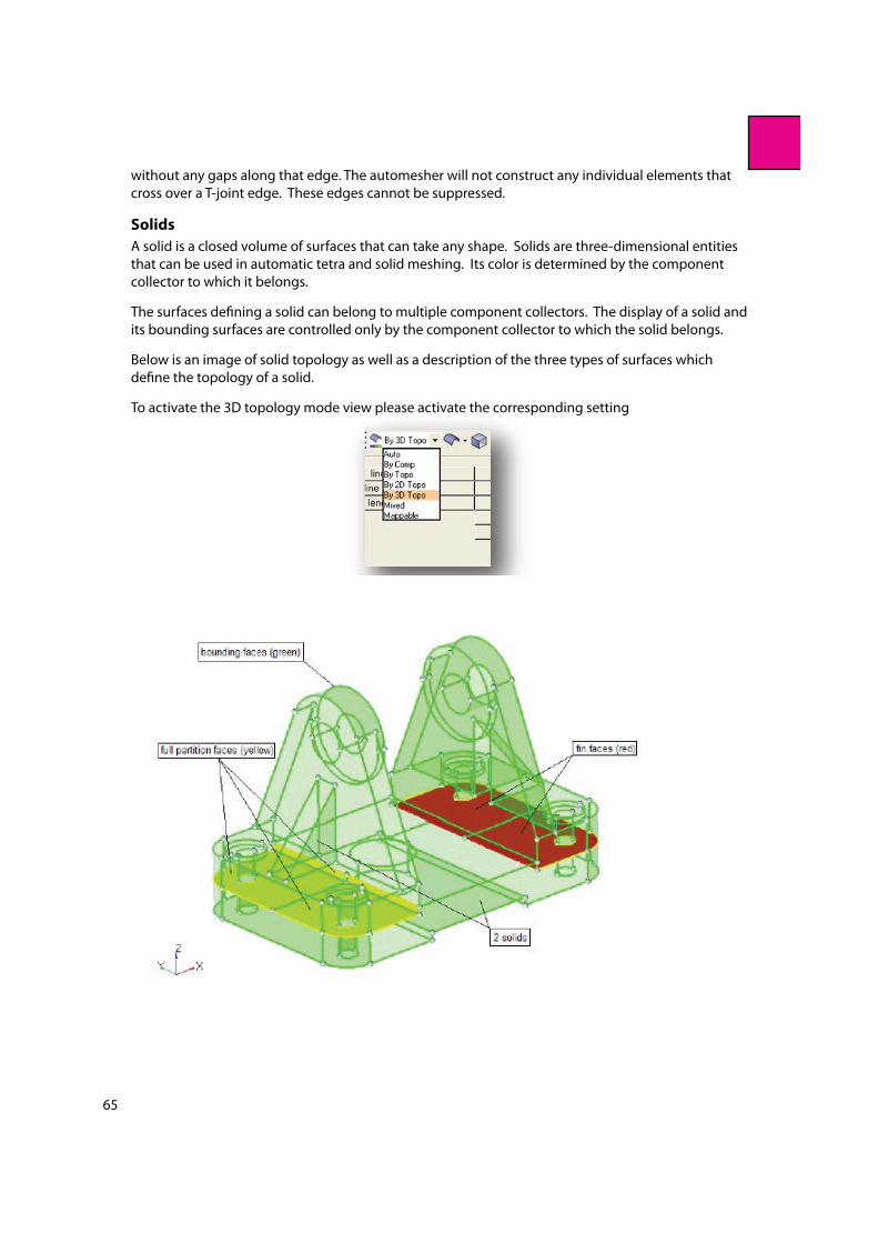
Solids
A solid is a closed volume of surfaces that can take any shape. Solids are three-dimensional entities
that can be used in automatic tetra and solid meshing. Its color is determined by the component
collector to which it belongs.
The surfaces de"ning a solid can belong to multiple component collectors. The display of a solid and
its bounding surfaces are controlled only by the component collector to which the solid belongs.
Below is an image of solid topology as well as a description of the three types of surfaces which
de"ne the topology of a solid.
To activate the 3D topology mode view please activate the corresponding setting
66
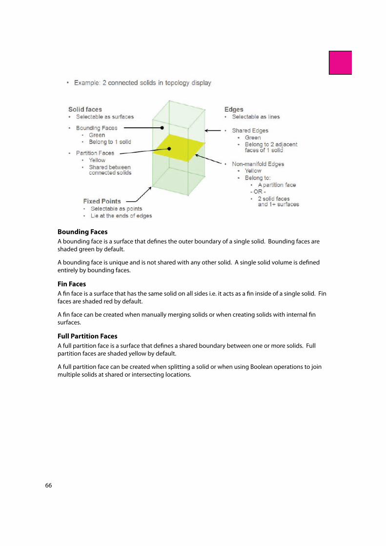
Bounding Faces
A bounding face is a surface that de"nes the outer boundary of a single solid. Bounding faces are
shaded green by default.
A bounding face is unique and is not shared with any other solid. A single solid volume is de"ned
entirely by bounding faces.
Fin Faces
A "n face is a surface that has the same solid on all sides i.e. it acts as a "n inside of a single solid. Fin
faces are shaded red by default.
A "n face can be created when manually merging solids or when creating solids with internal "n
surfaces.
Full Partition Faces
A full partition face is a surface that de"nes a shared boundary between one or more solids. Full
partition faces are shaded yellow by default.
A full partition face can be created when splitting a solid or when using Boolean operations to join
multiple solids at shared or intersecting locations.
67
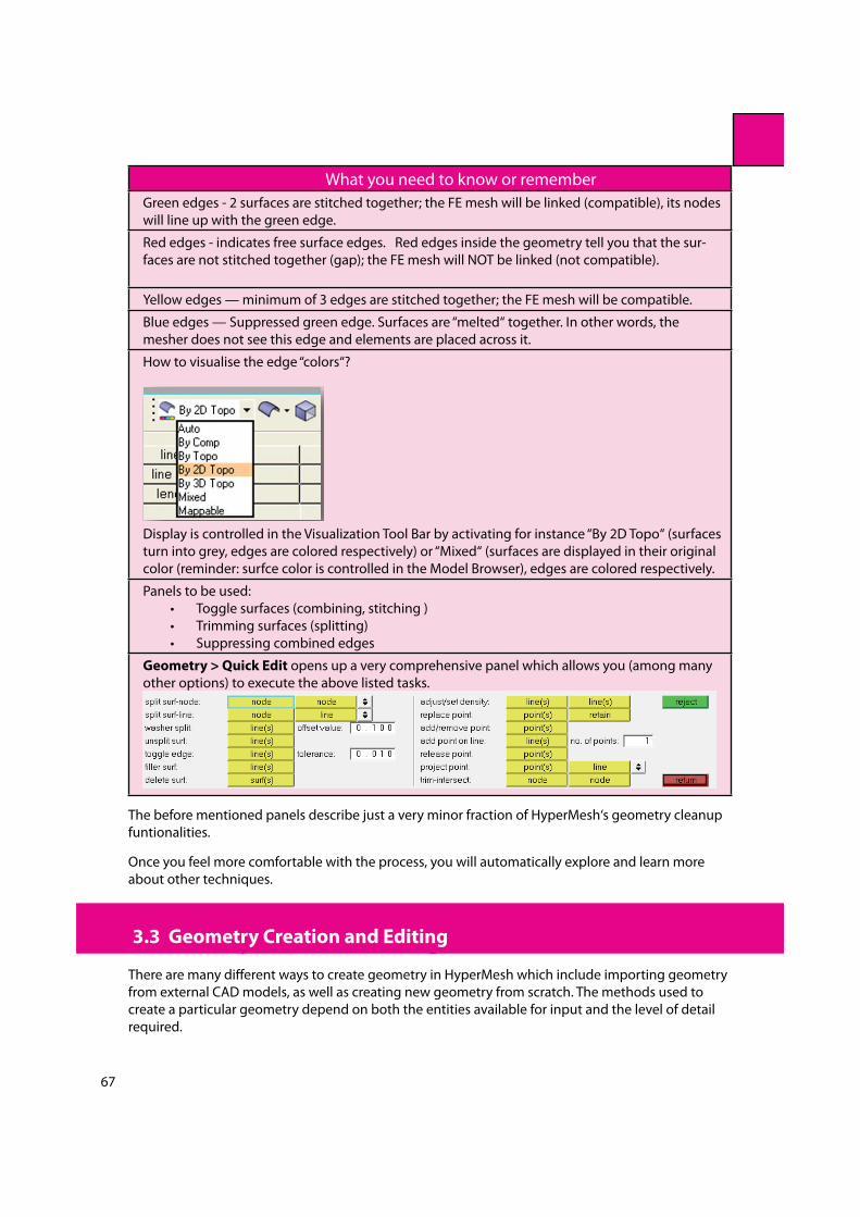
What you need to know or remember
Green edges - 2 surfaces are stitched together; the FE mesh will be linked (compatible), its nodes
will line up with the green edge.
Red edges - indicates free surface edges. Red edges inside the geometry tell you that the sur-
faces are not stitched together (gap); the FE mesh will NOT be linked (not compatible).
Yellow edges — minimum of 3 edges are stitched together; the FE mesh will be compatible.
Blue edges — Suppressed green edge. Surfaces are “melted“ together. In other words, the
mesher does not see this edge and elements are placed across it.
How to visualise the edge “colors“?
Display is controlled in the Visualization Tool Bar by activating for instance “By 2D Topo“ (surfaces
turn into grey, edges are colored respectively) or “Mixed“ (surfaces are displayed in their original
color (reminder: surfce color is controlled in the Model Browser), edges are colored respectively.
Panels to be used:
Toggle surfaces (combining, stitching )
Trimming surfaces (splitting)
Suppressing combined edges
Geometry > Quick Edit opens up a very comprehensive panel which allows you (among many
other options) to execute the above listed tasks.
The before mentioned panels describe just a very minor fraction of HyperMesh‘s geometry cleanup
funtionalities.
Once you feel more comfortable with the process, you will automatically explore and learn more
about other techniques.
3.3 Geometry Creation and Editing:
There are many di!erent ways to create geometry in HyperMesh which include importing geometry
from external CAD models, as well as creating new geometry from scratch. The methods used to
create a particular geometry depend on both the entities available for input and the level of detail
required.
3.3 Geometry Creation and Editing

68
The following is a list of the geometric entities which can be created and edited within HyperMesh:
Nodes
Free Points
Fixed Points
Lines
Faces
Surfaces
Solids
For each of these entities, we will investigate how they can be created.
Nodes
A node is the most basic "nite element entity. A node represents a physical position on the structure
being modeled and is used by an element entity to de"ne the location and shape of that element. It
is also used as temporary input to create geometric entities.
A node may contain a pointer to other geometric entities and can be associated directly to them.
For example, for a node to be translated along a surface, it must "rst be to associated to the surface.
A node is displayed as a small circle of sphere, depending on the mesh graphics mode. Its color is
always yellow.
Nodes are created using the menu bar by selecting Geometry > Create > Nodes and then selecting
a method to create the nodes with.
Free Points
A free point is a zero-dimensional geometry entity (for more information see: HyperMesh >
HyperMesh Entities & Solver Interfaces > Collectors and Collected Entities in the help) in space that is
not associated with a surface.
It is displayed as a small “x” and its color is determined by the component collector to which it
belongs. These types of points are typically used for weld locations and connectors.
Free points are created using the menu bar by selecting Geometry > Create > Free Points and then
selecting a method to create the free points with.
Fixed Points
A "xed point is a zero-dimensional geometry entity in space that is associated with a surface. Its
color is determined by the surface to which it is associated.
It is displayed as a small “o”. The automesher places an FE node at each "xed point on the surface
being meshed. These types of points are typically used for weld locations and connectors.
Fixed points are created using the menu bar by selecting Geometry > Create > Fixed Points and
then selecting a method to create the "xed points with.
Lines
A line represents a curve in space that is not attached to any surface or solid. A line is a one-
dimensional geometric entity. The color of a line is determined by the component collector to which
it belongs.
A line can be composed of one or more line types. Each line type in a line is referred to as a segment.
The end point of each line segment is connected to the "rst point of the next segment. A joint

69
is the common point between two line segments. Line segments are maintained as a single line
entity, so operations performed on the line a!ect each segment of the line. In general, HyperMesh
automatically uses the appropriate number and type of line segments to represent the geometry.
It is important to realize that lines are di!erent from surface edges and are sometimes handled
di!erently for certain HyperMesh operations.
Lines are created using the menu bar by selecting Geometry > Create > Lines and then selecting a
method to create the lines with.
Surfaces
A surface represents the geometry associated with a physical part. A surface is a two-dimensional
geometric entity that may be used in automatic mesh generation. Its color is determined by the
component collector to which it belongs.
A surface is comprised of one or more faces. Each face contains a mathematical surface and edges
to trim the surface, if required. When a surface has several faces, HyperMesh maintains all of
the faces as a single surface entity. Operations performed on the surface a!ect all the faces that
comprise the surface. In general, HyperMesh automatically uses the appropriate number of and
type of surface faces to represent the geometry.
Surfaces are created using the menu bar by selecting Geometry > Create > Surfaces and then
selecting a method to create the surfaces with.
Solids
A solid is a closed volume of surfaces that can take any shape. Solids are three-dimensional entities
that can be used in automatic tetra and solid meshing. Its color is determined by the component
collector to which it belongs.
The surfaces de"ning a solid can belong to multiple component collectors. The display of a solid and

70
its bounding surfaces are controlled only by the component collector to which the solid belongs.
Solids are created using the menu bar by selecting Geometry > Create > Solids and then selecting
a method to create the solids with.
Note & reminder: The newly created geometry will be placed /stored in the currently active component
collector. Check the Model Browser for the current component collector.
3.4 Importing CAD Geometry
To import geometry, the Import Browser, accessible through the Import Geometry icon , is
used.
Using the Import Browser, the user can import data from popular CAD packages such as
Unigraphics (NX2,NX3,NX4,NX5)
Supports import of .prt "les
Provides a UG part browser
Requires an installation of UG to be accessible, either locally or on a network
CATIA (V4,V5)
Supports import of .model (V4) "les
Additional license from Altair is required of .catpart (V5) "le import.
Pro/Engineer (Wild!re 2.0 & 3.0)
Supports import of .prt and .asm "les.
Additionally HyperMesh supports the import of the following intermediate translational languages:
IGES (.igs & .iges)
STEP (.stp)
3.4 Importing CAD Geometry

71
In addition, HyperMesh also supports the following CAD packages for Geometry Import:
ACIS
DXF
JT
Parasolid
PDGS
VDAFS
Advanced Import Options
The cleanup tolerance is used to determine if two surface edges are the same and if two surface
vertices are the same. The cleanup tol toggle controls the following items:
if two surface edges are close enough to be automatically combined into a shared edge
(green edges)
if a surface is degenerate and should be removed.
If you use the Automatic cleanup tolerance option, the complexity of the surface and edge
geometries are taken into account and a tolerance to maximize the shared edges (green edges) is
selected. The automatic cleanup tolerance value defaults to 100 times what is used internally by the
translator.
If you want to specify a di!erent value, use the Manual cleanup tolerance option, which must be
greater than the default value. The translator modi"es data only if the data stays within the original
data tolerance. Increasing the tolerance can cause serious problems. When this value is set, any
features equal to or less than the tolerance are eliminated. The translator does not include any
edge less than the tolerance long; if there are edges present that are important to the surface, that
surface will be distorted, or will fail to trim properly. Surfaces smaller than the tolerance may not be
imported. If the "le you have read has many very short edges, it may be worthwhile to reread the "le
using a larger tolerance. The same holds true if surfaces appear to be “inside out” when surface lines
are displayed. The tolerance value should not be set to a value greater than the node tolerance (set
in the Options panel) to be used for your element mesh. The Options panel is accessed through the
menu bar by selecting Preferences > Geometry Options.
If you are reading a Catia "le, you may need to override the tolerance in the "le; in our experience,
the tolerance in the "le is almost always too small (by at least an order of magnitude).
The Automatic option takes the complexity of the surfaces and edge geometries into
account and a tolerance to maximize shared edges (green edges) is selected.
The Manual option allows you to set a speci"c tolerance in the "eld.
1. The Import blanked (no show) components option allows you to control if blanked
components in the IGES translator will be imported into HyperMesh, as well as components
containing “NO SHOW” entities from the Catia translator.
2. Place a check in the Name components by layer option to activate this option. This option
is valid for Catia V4 and Catia V5.
For Catia V4, the option is enabled by default, and can’t be disabled.
For Catia V5, the option is disabled by default and can be enabled. If this option is
enabled, Catia objects from the same layer are grouped into the same component.