
HYGUARD Safety Couplings
32
Calibration Diagram Pressure Mpa Torque Nm 100 80 60 40 20 HYGUARD ® Safety Couplings owner’s choice Innovative Power Transmission
-
Upload
ropmachado -
Category
Documents
-
view
337 -
download
7
description
HYGUARD Safety Couplings
Transcript of HYGUARD Safety Couplings

Calibration Diagram
Pressure
Mpa
Torque
Nm
100
80
60
40
20
HYGUARD®
Safety Couplingsowner’s choice
Innovative Power Transmission
2 RENK Aktiengesellschaft, Rheine Works · Phone: + 49 5971 790 0 · Fax: + 49 5971 790 208 and 790 256
Safety Couplingsand Clamping Elements
The main task of overload protection systems being installed
in the drive of machineries is to safeguard valuable industrial
goods against unexpected overload stresses. Inspite of conti-
nuous modernization and technical advance of drive systems,
the risk of such damages has not become less, but even bigger.
The reason for this is the growing pressure which competition
is exerting on plant and machinery manufacturers, and the
thereby resulting necessity to continuously optimize their pro-
ducts. Over-dimensioning of vital components is no longer
deemed as necessary as it used to be in the past. Modern
computer techniques offer all possibilities to design essential
machinery components for permanent reliability while simulta-
neously meeting the requirements for lightweight construction.
In spite of all that, machinery failures due to suddenly occur-
ring unexpected overload cannot be excluded completely.
One single damage, however, may considerably exceed the
costs for efficient overload protection.
Now as before, appropriate safety equipment is necessary to
protect machinery. In the first place, safety couplings which
are nowadays available in a variety of different versions and
executions are used for this purpose in drive systems. How-
ever, not each of these couplings is suitable for every drive
application in the same way. The decisive criterion is the sum
of the factors which may contribute to the disturbance of the
operation processes. Therefore, new applications often also
require new safety systems.
The HYGUARD® safety coupling belongs to such protection
systems. Contrary to the shear-pin coupling it works after a
completely different operation principle.
The torque is transmitted by frictional engagement of the
contact faces of shaft and hub. If the preset torque is not
exceeded, it will work without slipping. If, however, the preset
torque value will be surpassed, the hydrostatic pressure is
released immediately, thus disconnecting the system.
Re-commissioning is possible within shortest time, as the
only thing to do is to set the system under pressure again.
Shear-pin couplings belong to the most well-known safety
devices. They fulfil their safety function by cutting-off the
bolts used for torque transmission at a predetermined nomi-
nal shear point as soon as the admissible torque has been
exceeded. Extensive test programmes, some of which were
carried out by scientific institutes, investigated the influence
of various parameters on the shearing behaviour. The results
led to the optimization of the pin geometry, whereby the relia-
bility of shear-pin couplings could be highly improved.
Since the function principle of such couplings is well known,
they are not treated in more detail here. The reason for descri-
bing the HYGUARD® Safety Coupling is not only because its
function is based on a different principle, but also because
the actual safety element is well suitable for other interesting
possibilities of application. One example is the possibility of
radial and axial positioning of gear wheels, hubs, and other
components on shafts or axis by means of the TORLOC®
clamping elements working on the same principle.
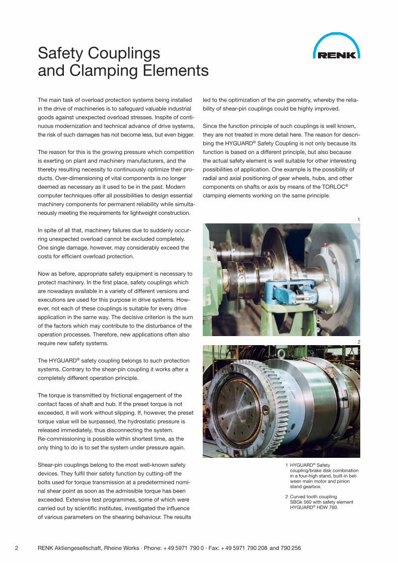
1 HYGUARD® Safetycoupling/brake disk combinationin a four-high stand, built-in bet-ween main motor and pinionstand gearbox.
2 Curved tooth coupling SBGk 560 with safety elementHYGUARD® HDW 760.
1
2
1
2
3
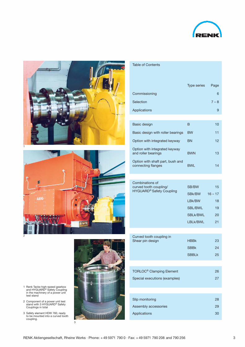
1 Renk Tacke high-speed gearboxand HYGUARD® Safety Couplingin the machinery of a power unittest stand
2 Component of a power unit teststand with 3 HYGUARD® SafetyCouplings in total
3 Safety element HDW 760, ready to be mounted into a curved tooth coupling.
Table of Contents
Type series Page
Commissioning 6
Selection 7 – 8
Applications 9
Basic design B 10
Basic design with roller bearings BW 11
Option with integrated keyway BN 12
Option with integrated keywayand roller bearings BWN 13
Option with shaft part, bush andconnecting flanges BWL 14
Combinations of curved tooth coupling/ SB/BW 15HYGUARD® Safety Coupling
SBk/BW 16 – 17
LBk/BW 18
SBL/BWL 19
SBLk/BWL 20
LBLk/BWL 21
Curved tooth coupling inShear pin design HBBk 23
SBBk 24
SBBLk 25
TORLOC® Clamping Element 26
Special executions (examples) 27
Slip monitoring 28
Assembly accessories 29
Applications 30
RENK Aktiengesellschaft, Rheine Works · Phone: + 49 5971 790 0 · Fax: + 49 5971 790 208 and 790 256 3
4 RENK Aktiengesellschaft, Rheine Works · Phone: + 49 5971 790 0 · Fax: + 49 5971 790 208 and 790 256
HYGUARD® Hydraulic Safety CouplingsTORLOC® Hydraulic Clamping Elements
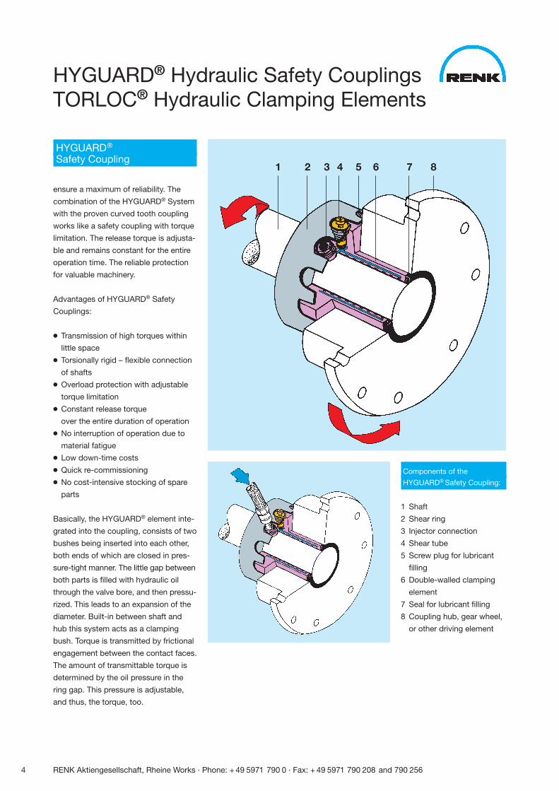
Components of the
HYGUARD® Safety Coupling:
1 Shaft
2 Shear ring
3 Injector connection
4 Shear tube
5 Screw plug for lubricant
filling
6 Double-walled clamping
element
7 Seal for lubricant filling
8 Coupling hub, gear wheel,
or other driving element
HYGUARD®
Safety Coupling
ensure a maximum of reliability. The
combination of the HYGUARD® System
with the proven curved tooth coupling
works like a safety coupling with torque
limitation. The release torque is adjusta-
ble and remains constant for the entire
operation time. The reliable protection
for valuable machinery.
Advantages of HYGUARD® Safety
Couplings:
● Transmission of high torques within
little space
● Torsionally rigid – flexible connection
of shafts
● Overload protection with adjustable
torque limitation
● Constant release torque
over the entire duration of operation
● No interruption of operation due to
material fatigue
● Low down-time costs
● Quick re-commissioning
● No cost-intensive stocking of spare
parts
Basically, the HYGUARD® element inte-
grated into the coupling, consists of two
bushes being inserted into each other,
both ends of which are closed in pres-
sure-tight manner. The little gap between
both parts is filled with hydraulic oil
through the valve bore, and then pressu-
rized. This leads to an expansion of the
diameter. Built-in between shaft and
hub this system acts as a clamping
bush. Torque is transmitted by frictional
engagement between the contact faces.
The amount of transmittable torque is
determined by the oil pressure in the
ring gap. This pressure is adjustable,
and thus, the torque, too.
1 2 3 4 5 6 7 8
RENK Aktiengesellschaft, Rheine Works · Phone: + 49 5971 790 0 · Fax: + 49 5971 790 208 and 790 256 5
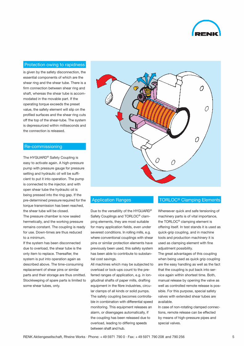
Protection owing to rapidness
is given by the safety disconnection, the
essential components of which are the
shear ring and the shear tube. There is a
firm connection between shear ring and
shaft, whereas the shear tube is accom-
modated in the movable part. If the
operating torque exceeds the preset
value, the safety element will slip on the
profiled surfaces and the shear ring cuts
off the top of the shear-tube. The system
is depressurized within milliseconds and
the connection is released.
Re-commissioning
The HYGUARD® Safety Coupling is
easy to activate again. A high-pressure
pump with pressure gauge for pressure
setting and hydraulic oil will be suffi-
cient to put it into operation. The pump
is connected to the injector, and with
open shear tube the hydraulic oil is
being pressed into the ring gap. If the
pre-determined pressure required for the
torque transmission has been reached,
the shear tube will be closed.
The pressure chamber is now sealed
hermetically, and the working pressure
remains constant. The coupling is ready
for use. Down-times are thus reduced
to a minimum.
If the system has been disconnected
due to overload, the shear tube is the
only item to replace. Thereafter, the
system is put into operation again as
described above. The time-consuming
replacement of shear pins or similar
parts and their storage are thus omitted.
Stockkeeping of spare parts is limited to
some shear tubes, only.
Application Ranges
Due to the versatility of the HYGUARD®
Safety Couplings and TORLOC® clam-
ping elements, they are most suitable
for many application fields, even under
severest conditions. In rolling mills, e.g.
where conventional couplings with shear
pins or similar protection elements have
previously been used, this safety system
has been able to contribute to substan-
tial cost savings.
All machines which may be subjected to
overload or lock-ups count to the pre-
ferred ranges of application, e.g. in lon-
gitudinal shafts of paper mills, drafting
equipment in the fibre industries, circu-
lar clamps of all kinds or solid pumps.
The safety coupling becomes controlla-
ble in combination with differential speed
monitoring. This equipment releases an
alarm, or disengages automatically, if
the coupling has been released due to
overload, leading to differing speeds
between shaft and hub.
TORLOC® Clamping Elements
Whereever quick and safe tensioning of
machinery parts is of vital importance,
the TORLOC® clamping element is
offering itself. In test stands it is used as
quick-grip coupling, and in machine
tools and production machinery it is
used as clamping element with fine
adjustment possibility.
The great advantages of this coupling
when being used as quick grip coupling
are the easy handling as well as the fact
that the coupling is put back into ser-
vice again within shortest time. Both,
manual release by opening the valve as
well as controlled remote release is pos-
sible. For this purpose, special safety
valves with extended shear tubes are
available.
In case of non-rotating clamped connec-
tions, remote release can be effected
by means of high-pressure pipes and
special valves.
6 RENK Aktiengesellschaft, Rheine Works · Phone: + 49 5971 790 0 · Fax: + 49 5971 790 208 and 790 256
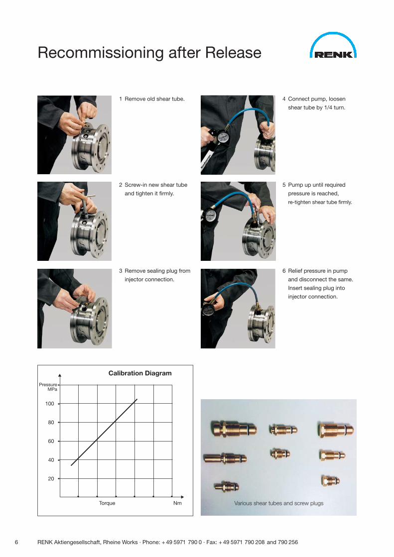
Recommissioning after Release
1 Remove old shear tube.
2 Screw-in new shear tube
and tighten it firmly.
3 Remove sealing plug from
injector connection.
4 Connect pump, loosen
shear tube by 1/4 turn.
5 Pump up until required
pressure is reached,
re-tighten shear tube firmly.
6 Relief pressure in pump
and disconnect the same.
Insert sealing plug into
injector connection.
PressureMPa
100
80
60
40
20
Torque Nm
Calibration Diagram�
�
Various shear tubes and screw plugs
RENK Aktiengesellschaft, Rheine Works · Phone: + 49 5971 790 0 · Fax: + 49 5971 790 208 and 790 256 7
Selection
Selection
The size of the HYGUARD®
safety coupling must be cho-
sen primarily according to
the peak torque to be trans-
mitted. For selection of the
design, the dimensions of the
machine parts to be connec-
ted and the application itself
are of importance. It is essen-
tial to pay attention to the
following recommendations
to achieve a safe and reliable
design.
Torque
For the various designs, each
coupling size indicated in the
selection tables is assigned a
torque range which can be
considered the optimum appli-
cation range. Values outside of
these limits may also be per-
missible depending on the
application involved. Please
consult us in such cases. As a
rule, however, the release tor-
que shall be within this range.
Normally, a coupling is selec-
ted with a maximum permissi-
ble torque of approximately
1.5 times to twice the amount
of operating torque to be
transmitted. In rotating drive
applications, a shock factor
must also be taken into ac-
count. This factor depends on
the driving machine. The
values are indicated in Table 1.
Thus:
1,5 · TN ≤ Tperm · KS
TN = Normal operating
torque (Nm)
Tperm = Maximum permissible
torque of the coupling
(Nm)
KS = Shock factor in
accordance with
Table 1
The following applies as a
guide value for determining
the release torque:
TA ≥ 1,2 · Tmax
TA = Release torque (Nm)
Tmax = Max. occuring opera-
ting torque (Nm)
The release torque determi-
ned in this way must lie
within the chosen coupling’s
torque range. When checking
this value, the following con-
dition must be fulfilled:
TA ≤ Tperm · KS
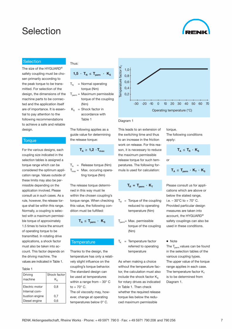
Temperature
Thanks to the design, the
temperature has only a relati-
vely slight influence on the
coupling’s torque behavior.
The standard design can
be used at temperatures
within a range from – 30° C
to + 70° C.
The oil viscosity may, how-
ever, change at operating
temperatures below 0° C.
Driving Shock factor
machine KS
Electric motor 0,8
Internal com-
bustion engine 0,7
Diesel engine 0,6
This leads to an extension of
the switching time and thus
to an increase in the friction
work on release. For this rea-
son, it is necessary to reduce
the maximum permissible
release torque for such tem-
peratures. The following for-
mula is used for calculation:
TR = Tperm · KT
TR = Torque of the coupling
reduced to operating
temperature (Nm)
Tperm= Max. permissible
torque of the coupling
(Nm)
TK = Temperature factor
referred to operating
temperature
As when making a choice
without the temperature fac-
tor, the calculation must also
include the shock factor KS
for rotary drives as indicated
in Table 1. Then check
whether the required release
torque lies below the redu-
ced maximum permissible
Tem
per
atur
e fa
ctor
KT
1,0
0,8
0,6
0,4
0,2
-30 -20 -10 0 10 20 30 40 50 60 70
Operating temperature (°C)
Diagram 1
torque.
The following conditions
apply:
TA ≤ TR · KS
or
TA ≤ Tperm · KT · KS
Please consult us for appli-
cations which are above or
below the stated range,
i.e. – 30°C to + 70° C.
Provided particular design
measures are taken into
account, the HYGUARD®
safety couplings can also be
used in these conditions.
● Note
The Tperm values can be found
in the selection tables of the
various coupling types.
The upper value of the torque
range applies in each case.
The temperature factor KT
is to be determined from
Diagram 1.
Table 1
8 RENK Aktiengesellschaft, Rheine Works · Phone: + 49 5971 790 0 · Fax: + 49 5971 790 208 and 790 256
Selection
Bearings
Depending on the applicati-
on, HYGUARD® safety cou-
plings are supplied with stan-
dard slide bearings, or with
built-in roller bearings.
As far as the slide bearing
options are concerned, the
relevant restrictions and limi-
tations have to be observed
in order to avoid wear and
unacceptable heating. As
such, the sliding velocity
after release shall not exceed
the value of 1,5 m/s. A maxi-
mum value of 1 N/mm2 is
applicable for the surface
loading of the bearing.
The verification of the surfa-
ce pressure considering the
influence of the radial forces
can be effected by means of
the following formula:
For safety couplings of the
construction series B:
FP = 1,2 · d1
2
For safety couplings of the
construction series BN:
FP = D · d2 · 0,9
P = surface pressure of
the bearing (N/mm2)
F = radial force acting
on the bearing (N)
d1, d2 = bearing diameter
(mm) acc. to selec-
tion table B, BN
D = length dimension
(mm) acc. to selec-
tion table BN
In both cases, the calculation
must result in a value which
meets the following condition:
P <_ 1 N /mm2
If this value is exceeded, the
next larger size, or a design
with roller bearings has to be
selected. The same holds
good for applications requi-
ring higher speeds than the
max. speeds which are indi-
cated in the selection tables.
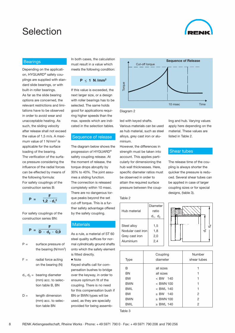
Sequence of release
The diagram below shows the
progression of HYGUARD®
safety coupling release. At
the moment of release, the
torque drops abruptly by
30% to 40%. The joint assu-
mes a sliding function.
The connection is released
completely within 10 msec.
There are no dangerous tor-
que peaks beyond the set
cut-off torque. This is a fur-
ther safety advantage offered
by the safety coupling.
Materials
As a rule, a material of ST 60
steel quality suffices for nor-
mal cylindrically ground shafts
onto which the safety element
is fitted directly.
● Note
Keyed shafts call for com-
pensation bushes to bridge
over the keyway, in order to
ensure optimum fit of the
coupling. There is no need
for this compensation bush if
BN or BWN types will be
used, as they are specially
provided for being assemb-
Diagram 2
Table 2
Diameter
Hub material ratio
d1, d2
Steel alloy 1,5
Nodular cast iron 1,8
Grey cast iron 2,0
Aluminium 2,4
Shear tubes
The release time of the cou-
pling is always shorter the
quicker the pressure is redu-
ced. Several shear tubes can
be applied in case of larger
coupling sizes or for special
designs, (table 3).
Table 3
Torq
ue
10 msec Time
Sequence of ReleaseCut-off torque
led with keyed shafts.
Various materials can be used
as hub material, such as steel
alloys, grey cast iron or alu-
minium.
However, the differences in
strength must be taken into
account. This applies parti-
cularly for dimensioning the
hub wall thicknesses. Here,
specific diameter ratios must
be observed in order to
attain the required surface
pressure between the coup-
ling and hub. Varying values
apply here depending on the
material. These values are
listed in Table 2.
Coupling Number
Type diameter shear tubes
B all sizes 1
BN all sizes 1
BW < BW 140 1
BWN < BWN 100 1
BWL < BWL 140 1
BW ≥ BW 140 2
BWN ≥ BWN 100 2
BWL ≥ BWL 140 2
RENK Aktiengesellschaft, Rheine Works · Phone: + 49 5971 790 0 · Fax: + 49 5971 790 208 and 790 256 9
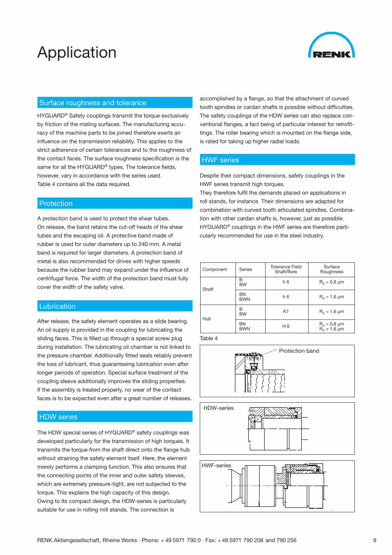
Application
Surface roughness and tolerance
HYGUARD® Safety couplings transmit the torque exclusively
by friction of the mating surfaces. The manufacturing accu-
racy of the machine parts to be joined therefore exerts an
influence on the transmission reliability. This applies to the
strict adherence of certain tolerances and to the roughness of
the contact faces. The surface roughness specification is the
same for all the HYGUARD® types. The tolerance fields,
however, vary in accordance with the series used.
Table 4 contains all the data required.
Protection
A protection band is used to protect the shear tubes.
On release, the band retains the cut-off heads of the shear
tubes and the escaping oil. A protective band made of
rubber is used for outer diameters up to 240 mm. A metal
band is required for larger diameters. A protection band of
metal is also recommended for drives with higher speeds
because the rubber band may expand under the influence of
centrifugal force. The width of the protection band must fully
cover the width of the safety valve.
Lubrication
After release, the safety element operates as a slide bearing.
An oil supply is provided in the coupling for lubricating the
sliding faces. This is filled up through a special screw plug
during installation. The lubricating oil chamber is not linked to
the pressure chamber. Additionally fitted seals reliably prevent
the loss of lubricant, thus guaranteeing lubrication even after
longer periods of operation. Special surface treatment of the
coupling sleeve additionally improves the sliding properties.
If the assembly is treated properly, no wear of the contact
faces is to be expected even after a great number of releases.
HDW series
The HDW special series of HYGUARD® safety couplings was
developed particularly for the transmission of high torques. It
transmits the torque from the shaft direct onto the flange hub
without straining the safety element itself. Here, the element
merely performs a clamping function. This also ensures that
the connecting points of the inner and outer safety sleeves,
which are extremely pressure-tight, are not subjected to the
torque. This explains the high capacity of this design.
Owing to its compact design, the HDW-series is particularly
suitable for use in rolling mill stands. The connection is
accomplished by a flange, so that the attachment of curved
tooth spindles or cardan shafts is possible without difficulties.
The safety couplings of the HDW series can also replace con-
ventional flanges, a fact being of particular interest for retrofit-
tings. The roller bearing which is mounted on the flange side,
is rated for taking up higher radial loads.
HWF series
Despite their compact dimensions, safety couplings in the
HWF series transmit high torques.
They therefore fulfil the demands placed on applications in
roll stands, for instance. Their dimensions are adapted for
combination with curved tooth articulated spindles. Combina-
tion with other cardan shafts is, however, just as possible.
HYGUARD® couplings in the HWF series are therefore parti-
cularly recommended for use in the steel industry.
Table 4
Protection band
HDW-series
HWF-series
Tolerance Field SurfaceComponent Series Shaft/Bore Roughness
B h 6 RA = 0,8 µm
ShaftBW
BN h 6 RA = 1,6 µmBWN
B K7 RA = 1,6 µm
HubBW
BN H 6 RA = 0,8 µmBWN RA = 1,6 µm
10 RENK Aktiengesellschaft, Rheine Works · Phone: + 49 5971 790 0 · Fax: + 49 5971 790 208 and 790 256
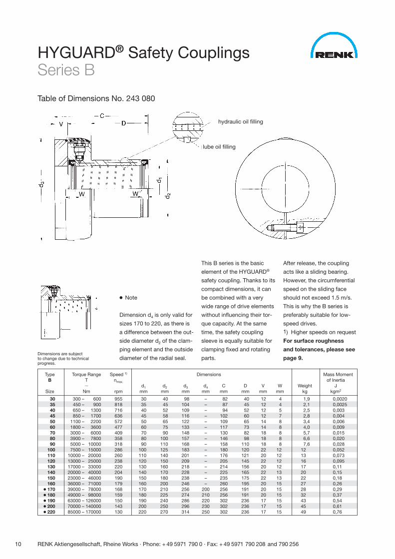
HYGUARD® Safety CouplingsSeries B
Table of Dimensions No. 243 080
● Note
Dimension d4 is only valid for
sizes 170 to 220, as there is
a difference between the out-
side diameter d2 of the clam-
ping element and the outside
diameter of the radial seal.
This B series is the basic
element of the HYGUARD®
safety coupling. Thanks to its
compact dimensions, it can
be combined with a very
wide range of drive elements
without influencing their tor-
que capacity. At the same
time, the safety coupling
sleeve is equally suitable for
clamping fixed and rotating
parts.
After release, the coupling
acts like a sliding bearing.
However, the circumferential
speed on the sliding face
should not exceed 1.5 m/s.
This is why the B series is
preferably suitable for low-
speed drives.1) Higher speeds on request
For surface roughness
and tolerances, please see
page 9.
Type Torque Range Speed 1) Dimensions Mass MomentB T nmax. of Inertia
� d1 d2 d3 d4 C D V W Weight JSize Nm rpm mm mm mm mm mm mm mm mm kg kgm2
30 300 – 600 955 30 40 98 – 82 40 12 4 1,9 0,002035 450 – 900 818 35 45 104 – 87 45 12 4 2,1 0,002540 650 – 1300 716 40 52 109 – 94 52 12 5 2,5 0,00345 850 – 1700 636 45 58 116 – 102 60 12 7 2,8 0,00450 1100 – 2200 572 50 65 122 – 109 65 14 8 3,4 0,00660 1800 – 3600 477 60 75 133 – 117 73 14 8 4,0 0,00970 3000 – 6000 409 70 90 148 – 130 82 18 8 5,7 0,01580 3900 – 7800 358 80 100 157 – 146 98 18 8 6,6 0,02090 5000 – 10000 318 90 110 168 – 158 110 18 8 7,6 0,028
100 7500 – 15000 286 100 125 183 – 180 120 22 12 12 0,052110 10000 – 20000 260 110 140 201 – 176 121 20 12 13 0,073120 13000 – 25000 238 120 150 209 – 205 145 22 12 16 0,095130 17000 – 33000 220 130 160 218 – 214 156 20 12 17 0,11140 20000 – 40000 204 140 170 228 – 225 165 22 13 20 0,15150 23000 – 46000 190 150 180 238 – 235 175 22 13 22 0,18160 36000 – 71000 179 160 200 246 – 260 195 20 15 27 0,26
● 170 39000 – 78000 168 170 210 256 200 256 191 20 15 28 0,29● 180 49000 – 98000 159 180 225 274 210 256 191 20 15 32 0,37● 190 63000 – 126000 150 190 240 286 220 302 236 17 15 43 0,54● 200 70000 – 140000 143 200 250 296 230 302 236 17 15 45 0,61● 220 85000 – 170000 130 220 270 314 250 302 236 17 15 49 0,76
lube oil filling
hydraulic oil filling
Dimensions are subjectto change due to technicalprogress.
RENK Aktiengesellschaft, Rheine Works · Phone: + 49 5971 790 0 · Fax: + 49 5971 790 208 and 790 256 11
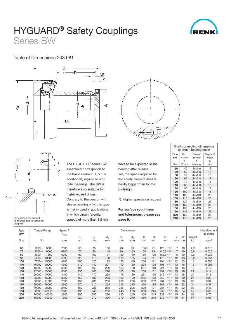
HYGUARD® Safety CouplingsSeries BW
Table of Dimensions 243 081
Dimensions are subjectto change due to technicalprogress.
The HYGUARD® series BW
essentially corresponds to
the basic element B, but is
additionally equipped with
roller bearings. The BW is
therefore also suitable for
higher-speed drives.
Contrary to the version with
sleeve bearing only, this type
is mainly used in applications
in which circumferential
speeds of more than 1,5 m/s
have to be expected in the
bearing after release.
Yet, the space required by
the safety element itself is
hardly bigger than for the
B-design.
1) Higher speeds on request
For surface roughness
and tolerances, please see
page 9.
Type Torque Range Speed 1) Dimensions MassMomentBW T nmax. of Inertia
� d1 d2 d3 d4 d5 C D D1 V W Weight JSize Nm rpm mm mm mm mm mm mm mm mm mm mm kg kgm2
60 1800 – 3600 7500 60 75 136 78 90 136,5 75 128 +/-0,2 7 10 4,9 0,01270 3000 – 6000 6700 70 90 148 90 100 150 84 140,5 +/-0,2 7 10 6,6 0,02080 3900 – 7800 6000 80 100 157 100 110 166 100 156,5 +/-0,2 8 10 7,6 0,02590 5000 – 10000 5300 90 110 168 115 125 184 111 170 +/-0,2 12 13 9,2 0,037100 7500 – 15000 4800 100 125 183 125 140 206 121 191 +/-0,2 12 13 14 0,065110 10000 – 20000 4300 110 140 201 140 150 208 125 193 +/-0,2 12 16 16 0,095120 13000 – 25000 3800 120 150 209 150 160 237 148 221 +/-0,2 13 16 19 0,12130 17000 – 33000 3600 130 160 218 165 170 250 161 234 +/-0,2 13 18 21 0,14140 20000 – 40000 3400 140 170 228 175 180 261 170 245 +/-0,2 13 18 24 0,19150 23000 – 46000 3000 150 180 238 190 190 275 182 259 +/-0,2 13 20 27 0,23160 36000 – 71000 2800 160 200 253 200 200 300 202 284 +/-0,2 13 20 32 0,32170 39000 – 78000 2600 170 210 258 215 215 300 198 282 +/-0,2 15 22 34 0,37180 49000 – 98000 2400 180 225 273 225 225 300 197 281 +/-0,2 16 22 38 0,46190 63000 –126000 2200 190 240 286 240 250 350 245 332 +/-0,2 15 24 50 0,66200 70000 –140000 2200 200 250 296 250 250 350 245 332 +/-0,2 15 24 53 0,75220 85000 –170000 1900 220 270 320 270 270 350 245 332 +/-0,2 15 24 57 0,93
Shaft connecting dimensionsto attach bearing cover
Type Pitch Size of Depth ofBW Circle Thread Tread
e f gSize � mm Number mm
60 40 4xM 6 1370 50 4xM 6 1380 50 4xM 6 1390 65 4xM 8 18
100 70 4xM 8 18110 80 4xM 8 18120 90 4xM 8 18130 100 4xM 8 18140 105 4xM10 23150 115 4xM10 23160 120 4xM10 23170 130 4xM10 23180 135 4xM10 23190 145 4xM10 23200 150 4xM10 23220 175 4xM10 23
12 RENK Aktiengesellschaft, Rheine Works · Phone: + 49 5971 790 0 · Fax: + 49 5971 790 208 and 790 256
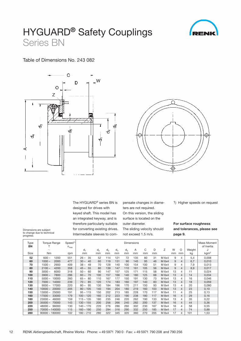
HYGUARD® Safety CouplingsSeries BN
Table of Dimensions No. 243 082
The HYGUARD® series BN is
designed for drives with
keyed shaft. This model has
an integrated keyway, and is
therefore particularly suitable
for converting existing drives.
Intermediate sleeves to com-
pensate changes in diame-
ters are not required.
On this version, the sliding
surface is located on the
outer diameter.
The sliding velocity should
not exceed 1.5 m/s.
Type Torque Range Speed1) Dimensions Mass MomentBN T nmax. of Inertia
� d1 d2 d3 d4 d5 A C D Z W O Weight JSize Nm rpm mm mm mm mm mm mm mm mm mm mm kg kgm2
52 600 – 1200 551 26 – 35 52 114 121 72 135 80 31 M 6x4 9 4 5,4 0,00860 1000 – 2000 477 30 – 40 60 119 131 90 145 95 46 M 6x4 9 4 6,7 0,01070 1500 – 2900 409 38 – 48 70 128 140 100 154 100 51 M 6x4 9 4 7,9 0,01380 2100 – 4200 358 45 – 55 80 139 147 110 161 105 56 M 6x4 9 4 8,9 0,01790 3000 – 6000 318 50 – 60 90 147 157 125 171 115 58 M 6x4 13 4 11 0,024
100 3900 – 7800 286 60 – 70 100 157 166 140 180 125 68 M 6x4 13 4 14 0,034110 5000 – 10000 260 65 – 80 110 167 177 150 191 130 73 M 6x4 13 4 16 0,046120 7000 – 14000 239 70 – 85 120 174 183 160 197 140 83 M 6x4 13 4 18 0,059130 9000 – 17000 220 80 – 95 130 184 196 170 211 150 93 M 8x4 13 4 20 0,080140 10000 – 20000 205 80 – 105 140 194 204 180 219 160 103 M 8x4 13 4 23 0,10150 13000 – 25000 191 95 – 115 150 202 213 185 228 170 117 M 8x4 11 4 25 0,13160 17000 – 33000 179 100 – 120 160 212 223 190 238 180 117 M 8x4 16 4 29 0,16180 23000 – 46000 159 115 – 135 180 235 246 220 262 190 133 M 8x4 13 4 35 0,22200 35000 – 70000 143 130 – 155 200 256 266 240 282 200 137 M 8x4 16 4 44 0,36220 48000 – 96000 130 140 – 170 220 276 286 260 302 230 167 M 8x4 16 4 58 0,55250 70000 – 140000 115 160 – 190 250 294 316 290 332 250 185 M 8x4 17 4 74 0,88280 90000 – 180000 102 180 – 210 280 322 345 320 360 270 205 M 8x4 17 4 101 1,53
1) Higher speeds on request
For surface roughness
and tolerances, please see
page 9.Dimensions are subjectto change due to technicalprogress.
RENK Aktiengesellschaft, Rheine Works · Phone: + 49 5971 790 0 · Fax: + 49 5971 790 208 and 790 256 13
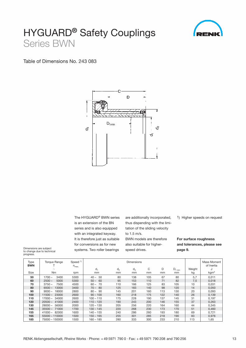
The HYGUARD® BWN series
is an extension of the BN
series and is also equipped
with an integrated keyway.
It is therefore just as suitable
for conversions as for new
systems. Two roller bearings
are additionally incorporated,
thus dispending with the limi-
tation of the sliding velocity
to 1.5 m/s.
BWN models are therefore
also suitable for higher-
speed drives.
Type Torque Range Speed 1) Dimensions Mass MomentBWN T nmax. of Inertia
� d1 d2 d3 C D D1 min Weight JSize Nm rpm mm mm mm mm mm mm kg kgm2
50 1700 – 3400 5300 40 – 50 80 138 105 67 80 5,7 0,01160 2500 – 5000 5300 50 – 60 95 153 110 71 82 7,5 0,01870 3750 – 7500 4500 60 – 70 110 166 125 83 105 10 0,03180 6500 – 13000 3400 70 – 80 125 183 140 98 120 14 0,05090 9000 – 18000 2800 80 – 90 145 201 160 113 130 20 0,093
100 11500 – 23000 2600 90 – 100 160 218 175 122 140 26 0,139110 17000 – 34000 2600 100 – 110 175 228 190 137 145 31 0,197120 20500 – 41000 2400 110 – 120 190 243 200 146 155 37 0,263130 28000 – 56000 2000 120 – 130 205 256 220 164 160 44 0,345145 35500 – 71000 1700 130 – 145 220 268 230 173 170 51 0,460155 41000 – 82000 1600 140 – 155 240 286 260 193 180 69 0,721165 55000 – 110000 1500 150 – 165 255 301 285 218 190 83 0,976185 75000 – 150000 1500 160 – 185 280 333 300 233 210 113 1,65
1) Higher speeds on request
For surface roughness
and tolerances, please see
page 9.
HYGUARD® Safety CouplingsSeries BWN
Table of Dimensions No. 243 083
Dimensions are subjectto change due to technicalprogress.
14 RENK Aktiengesellschaft, Rheine Works · Phone: + 49 5971 790 0 · Fax: + 49 5971 790 208 and 790 256
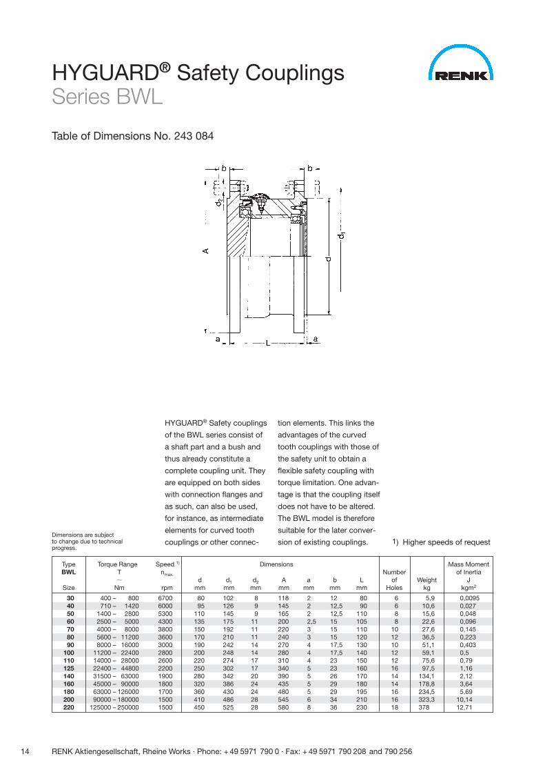
HYGUARD® Safety couplings
of the BWL series consist of
a shaft part and a bush and
thus already constitute a
complete coupling unit. They
are equipped on both sides
with connection flanges and
as such, can also be used,
for instance, as intermediate
elements for curved tooth
couplings or other connec-
tion elements. This links the
advantages of the curved
tooth couplings with those of
the safety unit to obtain a
flexible safety coupling with
torque limitation. One advan-
tage is that the coupling itself
does not have to be altered.
The BWL model is therefore
suitable for the later conver-
sion of existing couplings.
Type Torque Range Speed 1) Dimensions Mass MomentBWL T nmax. Number of Inertia
� d d1 d2 A a b L of Weight JSize Nm rpm mm mm mm mm mm mm mm Holes kg kgm2
30 400 – 800 6700 80 102 8 118 2 12 80 6 5,9 0,009540 710 – 1420 6000 95 126 9 145 2 12,5 90 6 10,6 0,02750 1400 – 2800 5300 110 145 9 165 2 12,5 110 8 15,6 0,04860 2500 – 5000 4300 135 175 11 200 2,5 15 105 8 22,6 0,09670 4000 – 8000 3800 150 192 11 220 3 15 110 10 27,6 0,14580 5600 – 11200 3600 170 210 11 240 3 15 120 12 36,5 0,22390 8000 – 16000 3000 190 242 14 270 4 17,5 130 10 51,1 0,403
100 11200 – 22400 2800 200 248 14 280 4 17,5 140 12 59,1 0,5110 14000 – 28000 2600 220 274 17 310 4 23 150 12 75,6 0,79125 22400 – 44800 2200 250 302 17 340 5 23 160 16 97,5 1,16140 31500 – 63000 1900 280 342 20 390 5 26 170 14 134,1 2,12160 45000 – 90000 1800 320 386 24 435 5 29 180 14 178,8 3,64180 63000 – 126000 1700 360 430 24 480 5 29 195 16 234,5 5,69200 90000 – 180000 1500 410 486 28 545 6 34 210 16 323,3 10,14220 125000 – 250000 1500 450 525 28 580 8 36 230 18 378 12,71
1) Higher speeds of request
HYGUARD® Safety CouplingsSeries BWL
Table of Dimensions No. 243 084
Dimensions are subjectto change due to technicalprogress.
RENK Aktiengesellschaft, Rheine Works · Phone: + 49 5971 790 0 · Fax: + 49 5971 790 208 and 790 256 15
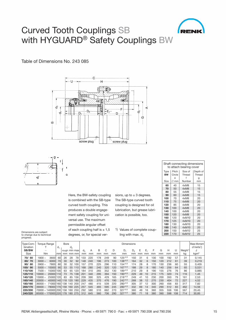
Here, the BW-safety coupling
is combined with the SB-type
curved tooth coupling. This
produces a double engage-
ment safety coupling for uni-
versal use. The maximum
permissible angular offset
of each coupling half is ± 1,5
degrees, or, for special ver-
sions, up to ± 3 degrees.
The SB-type curved tooth
coupling is designed for oil
lubrication, but grease lubri-
cation is possible, too.
1) Values of complete coup-
ling with max. d2
Curved Tooth Couplings SBwith HYGUARD® Safety Couplings BW
Table of Dimensions No. 243 085
Type Com- Torque Range Bore Dimensions Mass Momentbination T d1 d2 of Inertia1)SB/BW � rough min max d3 A B C D D1 D2 E E1 F G H U Weight1) J
Size Nm mm mm mm mm mm mm mm mm mm mm mm mm mm mm mm mm mm kg kgm2
70/ 60 1800 – 3600 60 26 28 78 133 220 178 249 90 125+0,5 150 31 6 130 100 192 57 31 0,14580/ 70 3000 – 6000 70 30 32 92 148 240 196 273 100 138+0,5 164 32 6 150 120 212 61 39 0,21990/ 80 3900 – 7800 80 30 32 100 157 270 225 296 110 154+0,5 174 28 8 170 130 236 60 55 0,405
100/ 90 5000 – 10000 90 53 55 110 168 280 240 320 120 167+0,5 188 29 8 180 140 256 64 65 0,531110/100 7500 – 15000 100 63 65 120 184 310 265 352 130 189+0,5 210 29 8 190 155 276 76 86 0,885125/110 10000 – 20000 110 73 75 138 201 340 295 394 150 190+0,5 229 49 10 215 175 320 74 116 1,45140/120 13000 – 25000 120 83 85 156 209 390 325 429 165 218+0,5 249 41 10 230 200 350 79 161 2,53160/140 20000 – 40000 140 118 120 180 229 435 370 476 190 242+0,5 268 38 12 270 230 404 72 227 4,52180/160 36000 – 71000 160 138 140 200 247 480 415 539 220 280+0,5 305 37 12 300 260 456 83 317 7,82200/170 39000 – 78000 170 158 160 225 257 545 465 595 245 280+0,5 332 69 14 340 290 512 83 462 14,56220/200 70000 – 140000 200 158 160 250 292 580 510 662 270 327+0,5 360 49 16 360 355 556 106 567 20,45240/220 85000 – 170000 220 178 180 275 312 645 560 706 290 327+0,5 380 71 18 380 390 598 108 714 30,85
Shaft connecting dimensionsto attach bearing cover
Type Pitch Size of Depth ofBW Circle Thread Thread
e f gSize � mm Number mm
60 40 4xM8 1570 50 4xM8 1580 55 4xM8 1590 60 4xM8 15
100 70 4xM8 20110 75 4xM8 20120 85 4xM8 20130 100 4xM8 20140 100 4xM8 20150 120 4xM8 20160 120 4xM10 20170 125 4xM10 20180 130 4xM10 20190 140 4xM10 20200 150 4xM12 25220 170 6xM12 25
Dimensions are subjectto change due to technicalprogress.
16 RENK Aktiengesellschaft, Rheine Works · Phone: + 49 5971 790 0 · Fax: + 49 5971 790 208 and 790 256
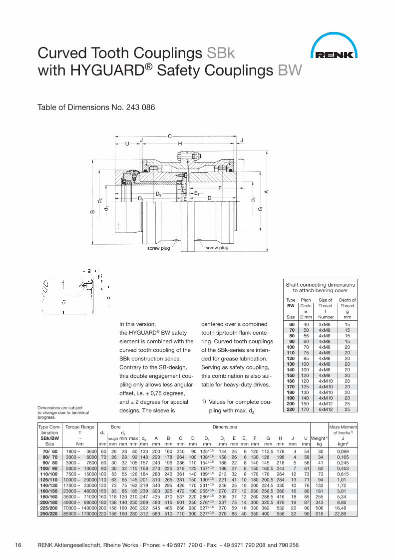
In this version,
the HYGUARD® BW safety
element is combined with the
curved tooth coupling of the
SBk construction series.
Contrary to the SB-design,
this double engagement cou-
pling only allows less angular
offset, i.e. ± 0,75 degrees,
and ± 2 degrees for special
designs. The sleeve is
centered over a combined
tooth tip/tooth flank cente-
ring. Curved tooth couplings
of the SBk-series are inten-
ded for grease lubrication.
Serving as safety coupling,
this combination is also sui-
table for heavy-duty drives.
1) Values for complete cou-
pling with max. d2
Type Com- Torque Range Bore Dimensionsbination T d1 d2
SBk/BW � rough min max d3 A B C D D1 D2 E E1 F G H J USize Nm mm mm mm mm mm mm mm mm mm mm mm mm mm mm mm mm mm mm
70/ 60 1800 – 3600 60 26 28 80 133 200 160 240 90 125+0,5 144 25 6 120 112,5 178 4 5480/ 70 3000 – 6000 70 26 28 92 148 220 178 264 100 138+0,5 158 26 6 130 128 198 4 5890/ 80 3900 – 7800 80 30 32 105 157 240 196 286 110 154+0,5 168 22 8 140 145 218 5 58
100/ 90 5000 – 10000 90 30 32 115 168 270 225 319 125 167+0,5 186 27 8 150 160,5 244 7 61110/100 7500 – 15000 100 53 55 126 184 280 240 361 140 189+0,5 213 32 8 170 176 264 12 73125/110 10000 – 20000 110 63 65 145 201 310 265 381 150 190+0,5 221 41 10 180 200,5 284 13 71140/130 17000 – 33000 130 73 75 162 219 340 295 426 170 231+0,5 246 25 10 200 224,5 330 10 76160/150 23000 – 46000 150 83 85 185 239 390 325 472 190 255+0,5 270 27 12 230 256,5 360 16 80180/160 36000 – 71000 160 118 120 210 247 435 370 537 220 280+0,5 305 37 12 260 288,5 416 18 85200/180 49000 – 98000 180 138 140 230 269 480 415 601 250 276+0,5 337 75 14 300 320,5 476 19 87225/200 70000 – 140000 200 158 160 260 292 545 465 666 280 327+0,5 370 59 16 330 362 532 22 90250/220 85000 – 170000 220 158 160 280 312 580 510 710 300 327+0,5 370 83 40 350 400 556 32 90
Mass Momentof Inertia1)
Weight1) Jkg kgm2
30 0,09934 0,16541 0,24562 0,46373 0,61594 1,01
132 1,72181 3,01255 5,34343 8,86506 16,48616 22,89
Curved Tooth Couplings SBkwith HYGUARD® Safety Couplings BW
Table of Dimensions No. 243 086
Shaft connecting dimensionsto attach bearing cover
Type Pitch Size of Depth ofBW Circle Thread Thread
e f gSize � mm Number mm
60 40 3xM8 1570 50 4xM8 1580 55 4xM8 1590 60 4xM8 15
100 70 4xM8 20110 75 4xM8 20120 85 4xM8 20130 100 4xM8 20140 100 4xM8 20150 120 4xM8 20160 120 4xM10 20170 125 4xM10 20180 130 4xM10 20190 140 4xM10 20200 150 4xM12 25220 170 6xM12 25Dimensions are subject
to change due to technicalprogress.
RENK Aktiengesellschaft, Rheine Works · Phone: + 49 5971 790 0 · Fax: + 49 5971 790 208 and 790 256 17
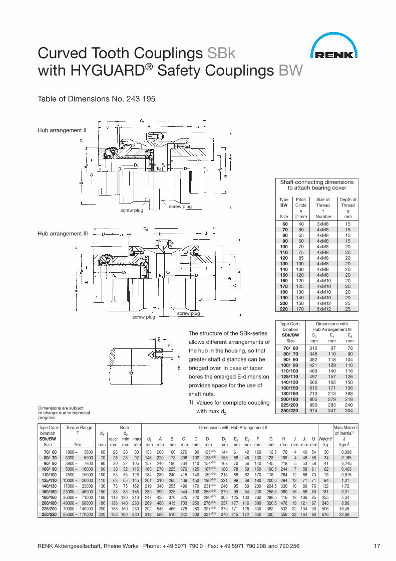
The structure of the SBk-series
allows different arrangements of
the hub in the housing, so that
greater shaft distances can be
bridged over. In case of taper
bores the enlarged E-dimension
provides space for the use of
shaft nuts.1) Values for complete coupling
with max d2
Type Com- Torque Range Bore Dimensions with Hub Arrangement II Mass Momentbination T d1 d2 of Inertia1)
SBk/BW � rough min max d3 A B C1 D D1 D2 E2 E3 F G H J J1 U Weight1) JSize Nm mm mm mm mm mm mm mm mm mm mm mm mm mm mm mm mm mm mm mm kg kgm2
70/ 60 1800 – 3600 60 26 28 80 133 200 160 276 90 125+0,5 144 61 42 120 112,5 178 4 40 54 30 0,09980/ 70 3000 – 6000 70 26 28 92 148 220 178 306 100 138+0,5 158 68 48 130 128 198 4 46 58 34 0,16590/ 80 3900 – 7800 80 30 32 105 157 240 196 334 110 154+0,5 168 70 56 140 145 218 5 53 58 41 0,245
100/ 90 5000 – 10000 90 30 32 115 168 270 225 370 125 167+0,5 186 78 59 150 160,5 244 7 58 61 62 0,463110/100 7500 – 15000 100 53 55 126 184 280 240 415 140 189+0,5 213 86 62 170 176 264 12 66 73 73 0,615125/110 10000 – 20000 110 63 65 145 201 310 265 439 150 190+0,5 221 99 68 180 200,5 284 13 71 71 94 1,01140/130 17000 – 33000 130 73 75 162 219 340 295 496 170 231+0,5 246 95 80 200 224,5 330 10 80 76 132 1,72160/150 23000 – 46000 150 83 85 185 239 390 325 544 190 255+0,5 270 99 84 230 256,5 360 16 88 80 181 3,01180/160 36000 – 71000 160 118 120 210 247 435 370 625 220 280+0,5 305 125 100 260 288,5 416 18 106 85 255 5,34200/180 49000 – 98000 180 138 140 230 269 480 415 703 250 276+0,5 337 177 116 300 320,5 476 19 121 87 343 8,86225/200 70000 – 140000 200 158 160 260 292 545 465 778 280 327+0,5 370 171 128 330 362 532 22 134 90 506 16,48250/220 85000 – 170000 220 158 160 280 312 580 510 842 300 327+0,5 370 215 172 350 400 556 32 164 90 616 22,89
Type Com- Dimensions withbination Hub Arrangement IIISBk/BW C2 E4 E5
Size mm mm mm
70/ 60 312 97 7880/ 70 348 110 9090/ 80 382 118 104
100/ 90 421 129 110110/100 469 140 116125/110 497 157 126140/130 566 165 150160/150 616 171 156180/160 713 213 188200/180 805 279 218225/200 890 283 240250/220 974 347 304
Shaft connecting dimensionsto attach bearing cover
Type Pitch Size of Depth ofBW Circle Thread Thread
e f gSize � mm Number mm
60 40 3xM8 1570 50 4xM8 1580 55 4xM8 1590 60 4xM8 15
100 70 4xM8 20110 75 4xM8 20120 85 4xM8 20130 100 4xM8 20140 100 4xM8 20150 120 4xM8 20160 120 4xM10 20170 125 4xM10 20180 130 4xM10 20190 140 4xM10 20200 150 4xM12 25220 170 6xM12 25
Hub arrangement II
Hub arrangement III
screw plug
screw plug
Curved Tooth Couplings SBkwith HYGUARD® Safety Couplings BW
Table of Dimensions No. 243 195
Dimensions are subjectto change due to technicalprogress.
screw plug
screw plug
18 RENK Aktiengesellschaft, Rheine Works · Phone: + 49 5971 790 0 · Fax: + 49 5971 790 208 and 790 256
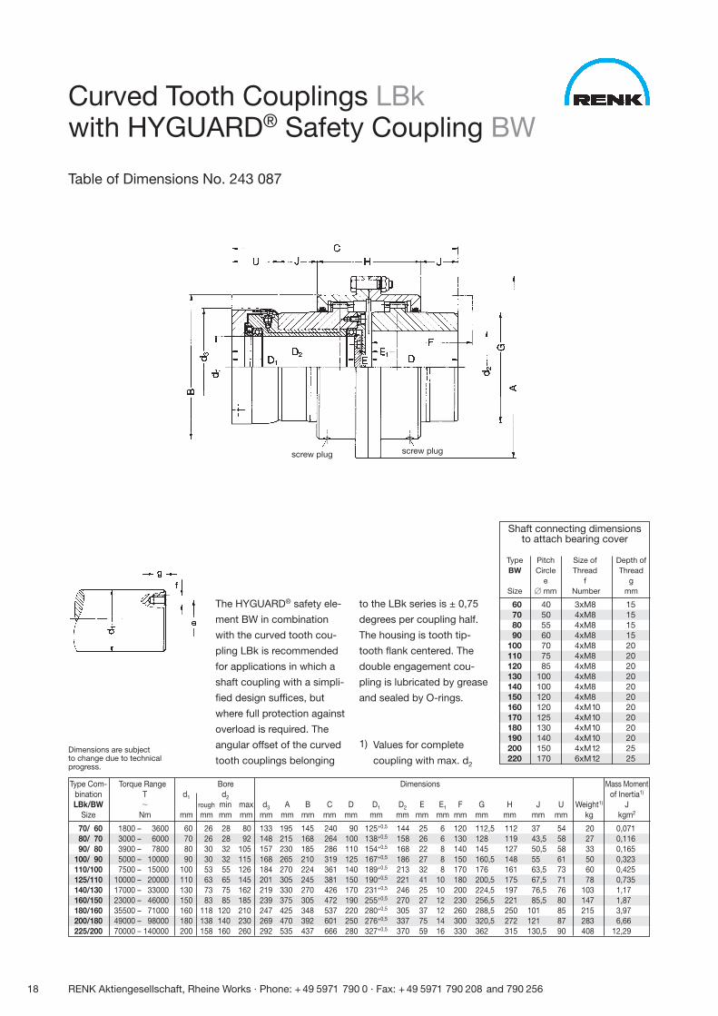
The HYGUARD® safety ele-
ment BW in combination
with the curved tooth cou-
pling LBk is recommended
for applications in which a
shaft coupling with a simpli-
fied design suffices, but
where full protection against
overload is required. The
angular offset of the curved
tooth couplings belonging
to the LBk series is ± 0,75
degrees per coupling half.
The housing is tooth tip-
tooth flank centered. The
double engagement cou-
pling is lubricated by grease
and sealed by O-rings.
1) Values for complete
coupling with max. d2
Type Com- Torque Range Bore Dimensions Mass Momentbination T d1 d2 of Inertia1)
LBk/BW � rough min max d3 A B C D D1 D2 E E1 F G H J U Weight1) JSize Nm mm mm mm mm mm mm mm mm mm mm mm mm mm mm mm mm mm mm kg kgm2
70/ 60 1800 – 3600 60 26 28 80 133 195 145 240 90 125+0,5 144 25 6 120 112,5 112 37 54 20 0,07180/ 70 3000 – 6000 70 26 28 92 148 215 168 264 100 138+0,5 158 26 6 130 128 119 43,5 58 27 0,11690/ 80 3900 – 7800 80 30 32 105 157 230 185 286 110 154+0,5 168 22 8 140 145 127 50,5 58 33 0,165
100/ 90 5000 – 10000 90 30 32 115 168 265 210 319 125 167+0,5 186 27 8 150 160,5 148 55 61 50 0,323110/100 7500 – 15000 100 53 55 126 184 270 224 361 140 189+0,5 213 32 8 170 176 161 63,5 73 60 0,425125/110 10000 – 20000 110 63 65 145 201 305 245 381 150 190+0,5 221 41 10 180 200,5 175 67,5 71 78 0,735140/130 17000 – 33000 130 73 75 162 219 330 270 426 170 231+0,5 246 25 10 200 224,5 197 76,5 76 103 1,17160/150 23000 – 46000 150 83 85 185 239 375 305 472 190 255+0,5 270 27 12 230 256,5 221 85,5 80 147 1,87180/160 35500 – 71000 160 118 120 210 247 425 348 537 220 280+0,5 305 37 12 260 288,5 250 101 85 215 3,97200/180 49000 – 98000 180 138 140 230 269 470 392 601 250 276+0,5 337 75 14 300 320,5 272 121 87 283 6,66225/200 70000 – 140000 200 158 160 260 292 535 437 666 280 327+0,5 370 59 16 330 362 315 130,5 90 408 12,29
Shaft connecting dimensionsto attach bearing cover
Type Pitch Size of Depth ofBW Circle Thread Thread
e f gSize � mm Number mm
60 40 3xM8 1570 50 4xM8 1580 55 4xM8 1590 60 4xM8 15
100 70 4xM8 20110 75 4xM8 20120 85 4xM8 20130 100 4xM8 20140 100 4xM8 20150 120 4xM8 20160 120 4xM10 20170 125 4xM10 20180 130 4xM10 20190 140 4xM10 20200 150 4xM12 25220 170 6xM12 25
screw plug
Curved Tooth Couplings LBkwith HYGUARD® Safety Coupling BW
Table of Dimensions No. 243 087
screw plug
Dimensions are subjectto change due to technicalprogress.
RENK Aktiengesellschaft, Rheine Works · Phone: + 49 5971 790 0 · Fax: + 49 5971 790 208 and 790 256 19
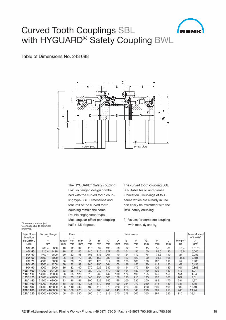
The HYGUARD® Safety coupling
BWL in flanged design combi-
ned with the curved tooth coup-
ling type SBL. Dimensions and
features of the curved tooth
coupling remain the same.
Double engagement type.
Max. angular offset per coupling
half ± 1.5 degrees.
The curved tooth coupling SBL
is suitable for oil and grease
lubrication. Couplings of this
series which are already in use
can easily be retrofitted with the
BWL safety coupling.
1) Values for complete coupling
with max. d1 and d2
Type Com- Torque Range Bore Dimensions Mass Momentbination T d1; d2 of Inertia1)
SBL/BWL � rough min max A B C D E F G H L Weight1) JSize Nm mm mm mm mm mm mm mm mm mm mm mm mm kg kgm2
30/ 30 400 – 800 10 12 32 118 92 190 50 87 75 45 55 80 10,4 0,016140/ 40 710 – 1420 20 22 46 145 115 227 60 104 90 60 68,5 90 18,6 0,04550/ 50 1400 – 2800 20 22 58 165 135 267 70 124 110 75 78,5 110 27 0,08360/ 60 2500 – 5000 26 28 70 200 160 288 80 122 120 90 91,5 105 41,8 0,18170/ 70 4000 – 8000 26 28 78 220 178 314 90 128 130 100 102 110 54 0,28380/ 80 5600 – 11200 30 32 92 240 196 344 100 138 150 120 112 120 69 0,43390/ 90 8000 – 16000 30 32 100 270 225 382 110 154 170 130 126 130 101 0,803
100/ 100 11200 – 22400 53 55 110 280 240 412 120 164 180 140 136 140 116 1,01110/ 110 14000 – 28000 63 65 120 310 265 442 130 174 190 155 146 150 151 1,64125/ 125 22400 – 44800 73 75 138 340 295 500 150 190 215 175 170 160 202 2,81140/ 140 31500 – 63000 83 85 156 390 325 540 165 200 230 200 185 170 281 4,57160/ 160 45000 – 90000 118 120 180 435 370 606 190 214 270 230 213 180 387 8,15180/ 180 63000 –126000 138 140 200 480 415 673 220 229 300 260 239 195 530 13,49200/ 200 90000 –180000 158 160 225 545 465 748 245 250 340 290 269 210 745 24,24220/ 220 125000 –250000 158 160 250 580 510 818 270 278 360 355 294 230 910 33,11
Curved Tooth Couplings SBLwith HYGUARD® Safety Coupling BWL
Table of Dimensions No. 243 088
screw plug screw plug
Dimensions are subjectto change due to technicalprogress.
20 RENK Aktiengesellschaft, Rheine Works · Phone: + 49 5971 790 0 · Fax: + 49 5971 790 208 and 790 256
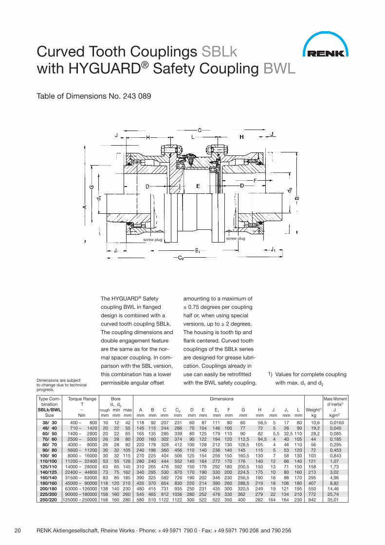
The HYGUARD® Safety
coupling BWL in flanged
design is combined with a
curved tooth coupling SBLk.
The coupling dimensions and
double engagement feature
are the same as for the nor-
mal spacer coupling. In com-
parison with the SBL version,
this combination has a lower
permissible angular offset
amounting to a maximum of
± 0.75 degrees per coupling
half or, when using special
versions, up to ± 2 degrees.
The housing is tooth tip and
flank centered. Curved tooth
couplings of the SBLk series
are designed for grease lubri-
cation. Couplings already in
use can easily be retrofitted
with the BWL safety coupling.
1) Values for complete coupling
with max. d1 and d2
Type Com- Torque Range Bore Dimensions Mass Momentbination T d1; d2 of Inertia1)
SBLk/BWL � rough min max A B C C2 D E E1 F G H J J1 L Weight1) JSize Nm mm mm mm mm mm mm mm mm mm mm mm mm mm mm mm mm kg kgm2
38/ 30 400 – 800 10 12 42 118 92 207 231 60 87 111 90 60 58,5 5 17 80 10,6 0,016348/ 40 710 – 1420 20 22 55 145 115 244 286 70 104 146 100 77 72 5 26 90 19,2 0,04560/ 50 1400 – 2800 20 22 65 165 135 285 339 80 125 179 110 90 82 5,5 32,5 110 28,2 0,08570/ 60 2500 – 5000 26 28 80 200 160 302 374 90 122 194 120 112,5 94,5 4 40 105 44 0,18580/ 70 4000 – 8000 26 28 92 220 178 328 412 100 128 212 130 128,5 105 4 46 110 56 0,29590/ 80 5600 – 11200 30 32 105 240 196 360 456 110 140 236 140 145 115 5 53 120 72 0,453
100/ 90 8000 – 16000 30 32 115 270 225 404 506 125 154 256 150 160,5 130 7 58 130 103 0,843110/100 11200 – 22400 53 55 126 280 240 444 552 140 164 272 170 176 140 12 66 140 121 1,07125/110 14000 – 28000 63 65 145 310 265 476 592 150 176 292 180 200,5 150 13 71 150 158 1,73140/125 22400 – 44800 73 75 162 340 295 530 670 170 190 330 200 224,5 175 10 80 160 213 3,02160/140 31500 – 63000 83 85 185 390 325 582 726 190 202 346 230 256,5 190 16 88 170 295 4,96180/160 45000 – 90000 118 120 210 435 370 654 830 220 214 390 260 288,5 219 18 106 180 407 8,82200/180 63000 – 126000 138 140 230 480 415 731 935 250 231 435 300 320,5 249 19 121 195 550 14,46225/200 90000 – 180000 158 160 260 545 465 812 1036 280 252 476 330 362 279 22 134 210 772 25,74250/220 125000 – 250000 158 160 280 580 510 1122 1122 300 522 522 350 400 282 164 164 230 942 35,01
Curved Tooth Couplings SBLkwith HYGUARD® Safety Coupling BWL
Table of Dimensions No. 243 089
screw plug screw plug
Dimensions are subjectto change due to technicalprogress.
RENK Aktiengesellschaft, Rheine Works · Phone: + 49 5971 790 0 · Fax: + 49 5971 790 208 and 790 256 21
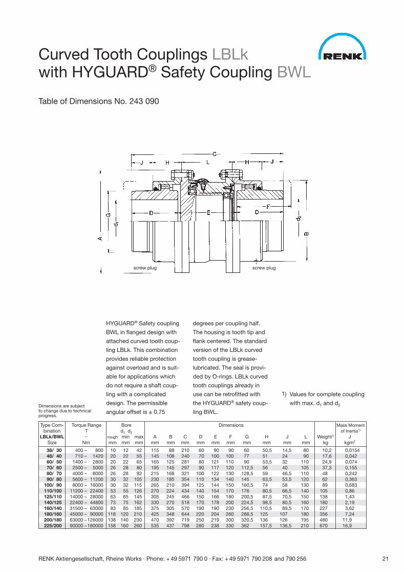
HYGUARD® Safety coupling
BWL in flanged design with
attached curved tooth coup-
ling LBLk. This combination
provides reliable protection
against overload and is suit-
able for applications which
do not require a shaft coup-
ling with a complicated
design. The permissible
angular offset is ± 0.75
degrees per coupling half.
The housing is tooth tip and
flank centered. The standard
version of the LBLk curved
tooth coupling is grease-
lubricated. The seal is provi-
ded by O-rings. LBLk curved
tooth couplings already in
use can be retrofitted with
the HYGUARD® safety coup-
ling BWL.
1) Values for complete coupling
with max. d1 and d2
Type Com- Torque Range Bore Dimensions Mass Momentbination T d1; d2 of Inertia1)
LBLk/BWL � rough min max A B C D E F G H J L Weight1) JSize Nm mm mm mm mm mm mm mm mm mm mm mm mm mm kg kgm2
38/ 30 400 – 800 10 12 42 115 88 210 60 90 90 60 50,5 14,5 80 10,2 0,015448/ 40 710 – 1420 20 22 55 145 108 240 70 100 100 77 51 24 90 17,6 0,04260/ 50 1400 – 2800 20 22 65 165 125 281 80 121 110 90 53,5 32 110 24,9 0,07470/ 60 2500 – 5000 26 28 80 195 145 297 90 117 120 112,5 56 40 105 37,3 0,15580/ 70 4000 – 8000 26 28 92 215 168 321 100 122 130 128,5 59 46,5 110 48 0,24290/ 80 5600 – 11200 30 32 105 230 185 354 110 134 140 145 63,5 53,5 120 62 0,363
100/ 90 8000 – 16000 30 32 115 265 210 394 125 144 150 160,5 74 58 130 89 0,683110/100 11200 – 22400 53 55 126 270 224 434 140 154 170 176 80,5 66,5 140 105 0,86125/110 14000 – 28000 63 65 145 305 245 466 150 166 180 200,5 87,5 70,5 150 138 1,43140/125 22400 – 44800 73 75 162 330 270 518 170 178 200 224,5 98,5 80,5 160 180 2,19160/140 31500 – 63000 83 85 185 375 305 570 190 190 230 256,5 110,5 89,5 170 227 3,62180/160 45000 – 90000 118 120 210 425 348 644 220 204 260 288,5 125 107 180 356 7,24200/180 63000 –126000 138 140 230 470 392 719 250 219 300 320,5 136 126 195 480 11,9225/200 90000 –180000 158 160 260 535 437 798 280 238 330 362 157,5 136,5 210 670 16,9
screw plug
Curved Tooth Couplings LBLkwith HYGUARD® Safety Coupling BWL
Table of Dimensions No. 243 090
Dimensions are subjectto change due to technicalprogress.
screw plug
22 RENK Aktiengesellschaft, Rheine Works · Phone: + 49 5971 790 0 · Fax: + 49 5971 790 208 and 790 256
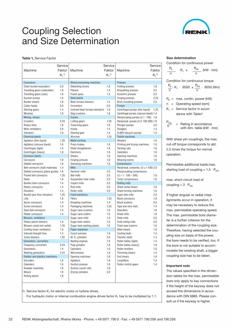
Coupling Selectionand Size Determination
Table 1, Service Factor
Service Service ServiceMachine Faktor Machine Faktor Machine Faktor
K11) K1
1) K11)
ExcavatorsChain bucket excavators 2,0Travelling gears (caterpillar) 1,8Travelling gears (rails) 1,6Suction pumps 1,6Bucket wheels 1,8Cutter heads 2,0Slewing gears 1,4Winches 1,6Mining, stonesCrushers 2,24Rotary kilns 1,8Mine ventilators 2,0Vibrators 1,6Chemical plantsAgitators (thin liquid) 1,25Agitators (viscous liquid) 1,6Centrifuges (light) 1,4Centrifuges (heavy) 1,8Conveyor plantsConveyors 1,8Slatted conveyors 1,6Belt conveyors (bulk materials) 1,4Slatted conveyors (piece goods) 1,6Pocket belt conveyors 1,25Reels 1,8Bucket chain conveyors 1,4Rotary conveyors 1,4Elevators 1,4Bucket type flour elevators 1,25Lifts 1,8Apron conveyors 1,4Screw conveyors 1,4Steel belt conveyors 1,4Redler conveyors 1,4Blowers, ventilatorsRotary piston blowers 1,4Blowers (axial and radial) 1,25Cooling tower ventilators 1,4Induced draught fans 1,4Turbo-blowers 1,25Generators, convertersFrequency converters 2,24Generators 1,4Welding generators 2,24Rubber and plastics machineryExtruders 1,6Calenders 1,6Kneader machines 1,8Mixers 1,8Rolling plants 1,8
Wood processing machinesDebarking drums 1,8Planers 1,4Frame saws 1,4Steel plantsBlast furnace blowers 1,4Converters 2,0Inclined blast furnace elevators 1,8Slag crushers 1,8CranesLuffing gears 1,25Traversing gears 1,6Hoists 1,4Slewing gear 1,4Winches 1,25Metal workingPress brakes 1,6Sheet straighteners 1,8Hammers 1,8Shears 1,6Forging presses 1,8Stamping machines 1,8MillsHammer mills 2,0Ball mills 2,0Suspended roller mills 2,0Impact mills 2,0Rod mills 2,0Roller mills 2,0Food machineryFillers 1,25Kneading machines 1,4Packaging machines 1,25Sugar cane crushers 1,6Sugar cane cutters 1,6Sugar cane mills 1,8Sugar beet cutters 1,6Sugar beet washing plants 1,6Paper machinesCouch presses 1,8M. G. cylinders 2,0Beating engines 1,6Pulp grinders 1,8Calenders 1,6Wet presses 1,8Opening machines 1,8Agitators 1,8Suction presses 1,6Suction couch rolls 1,8Drying cylinders 2,0
PressesFolding presses 1,8Briquetting presses 2,5Eccentric presses 2,0Forging presses 2,25Brick moulding presses 2,5PumpsCentrifugal pumps (thin liquid) 1,25Centrifugal pumps (viscous liquid) 1,4Reciprocating pumps (U 1 : 100) 1,8Reciprocat. pumps (U 2: 100-200) 1,6 Plunger pumps 2,0Sludgers 1,4ELMO-Vacuum pumps 1,5Textile machinesWinders 1,6Printing and drying machines 1,6Tanning vats 1,6Calenders 1,6Opening machines 1,6Weaving looms 1,6CompressorsReciprocat. compress. (U ≤ 1:100) 2,0Reciprocating compressors(U = 1 : 100 – 200) 1,6Turbo compressors 1,6Rolling millsSheet metal shears 1,8Sheet turning machines 1,6Ingot slab mills 2,0Block conveyors 1,8Block pushers 2,0Tape and wire reels 1,4Descalers 1,6Sheet mills 1,8Plate mills 2,0Cold rolling mills 2,0Track-type tractors 1,6Billet shears 1,8Cooling beds 1,4Transfer skids 1,4Roller tables (light) 1,4Roller tables (heavy) 1,8Roller levellers 1,6Trimming shears 1,4End shears 1,8Looplifters 1,4Roller control gears 1,4
1) Service factor K1 for electric motor or turbine drives.
For hydraulic motor or internal combustion engine drives factor K1 has to be multiplied by 1.1.
Size determination
Condition for continuous power
PN · K1 ≤PKN (kW · min)
n n
Condition for continuous torquePN · K1 · 9550 ≤
PKN · 9550 (Nm)n n
PN = max. contin. power (kW)
n = Operating speed (rpm)
K1 = Service factor in accor-
dance with Table1
PKN = Rating in accordancen
with dim. table (kW · min)
With shear pin couplings, the max.
cut-off torque corresponds to abt.
2,5 times the torque for normal
operation.
Permissible additional loads:max.
starting load of coupling = 1,5 · PKN
max. short-circuit load of
coupling = 3 · PKN
If higher angular or radial misa-
lignments occur in operation, it
may be necessary to reduce the
max. permissible operating speed.
The max. permissible bore diame-
ter is a further criterion for the
determination of the coupling size.
Therefore, having selected the cou-
pling size on basis of the power,
the bore needs to be verified, too. If
the bore is not suitable to accom-
modate the existing shaft, a bigger
coupling size has to be taken.
Important note
The values specified in the dimen-
sion tables for the max. permissible
bore only apply to key connections
if the height of the keyway does not
exceed the dimensions in accor-
dance with DIN 6885. Please con-
sult us if the keyway is higher.
RENK Aktiengesellschaft, Rheine Works · Phone: + 49 5971 790 0 · Fax: + 49 5971 790 208 and 790 256 23
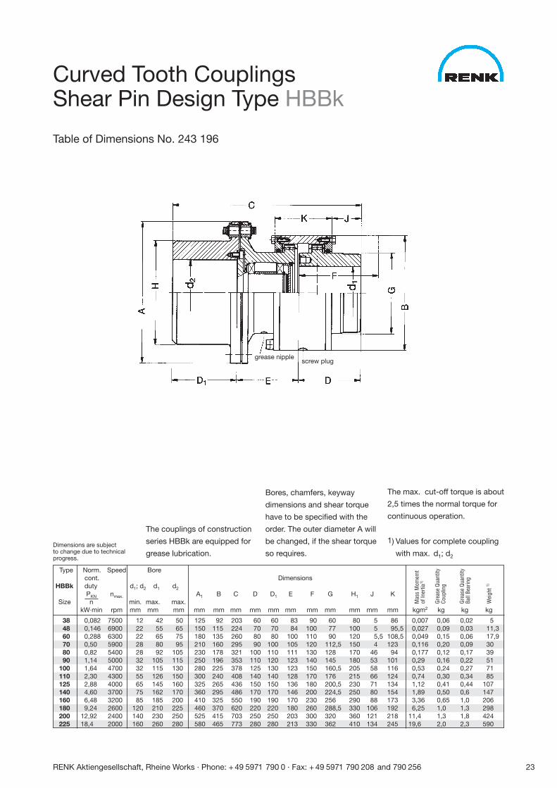
The couplings of construction
series HBBk are equipped for
grease lubrication.
Bores, chamfers, keyway
dimensions and shear torque
have to be specified with the
order. The outer diameter A will
be changed, if the shear torque
so requires.
The max. cut-off torque is about
2,5 times the normal torque for
continuous operation.
1) Values for complete coupling
with max. d1; d2
Type Norm. Speed Borecont. Dimensions
HBBk duty d1; d2 d1 d2
PKN nmax. A1 B C D D1 E F G H1 J KSize n min. max. max.
kW·min rpm mm mm mm mm mm mm mm mm mm mm mm mm mm mm kgm2 kg kg kg
38 0,082 7500 12 42 50 125 92 203 60 60 83 90 60 80 5 86 0,007 0,06 0,02 548 0,146 6900 22 55 65 150 115 224 70 70 84 100 77 100 5 95,5 0,027 0,09 0,03 11,360 0,288 6300 22 65 75 180 135 260 80 80 100 110 90 120 5,5 108,5 0,049 0,15 0,06 17,970 0,50 5900 28 80 95 210 160 295 90 100 105 120 112,5 150 4 123 0,116 0,20 0,09 3080 0,82 5400 28 92 105 230 178 321 100 110 111 130 128 170 46 94 0,177 0,12 0,17 3990 1,14 5000 32 105 115 250 196 353 110 120 123 140 145 180 53 101 0,29 0,16 0,22 51
100 1,64 4700 32 115 130 280 225 378 125 130 123 150 160,5 205 58 116 0,53 0,24 0,27 71110 2,30 4300 55 126 150 300 240 408 140 140 128 170 176 215 66 124 0,74 0,30 0,34 85125 2,88 4000 65 145 160 325 265 436 150 150 136 180 200,5 230 71 134 1,12 0,41 0,44 107140 4,60 3700 75 162 170 360 295 486 170 170 146 200 224,5 250 80 154 1,89 0,50 0,6 147160 6,48 3200 85 185 200 410 325 550 190 190 170 230 256 290 88 173 3,36 0,65 1,0 206180 9,24 2600 120 210 225 460 370 620 220 220 180 260 288,5 330 106 192 6,25 1,0 1,3 298200 12,92 2400 140 230 250 525 415 703 250 250 203 300 320 360 121 218 11,4 1,3 1,8 424225 18,4 2000 160 260 280 580 465 773 280 280 213 330 362 410 134 245 19,6 2,0 2,3 590
Mas
s M
omem
tof
Iner
tia1)
Grea
se Q
uant
ityCo
uplin
g
Grea
se Q
uant
ityBa
ll Be
arin
g
Wei
ght 1)
Curved Tooth CouplingsShear Pin Design Type HBBk
Table of Dimensions No. 243 196
grease nipplescrew plug
Dimensions are subjectto change due to technicalprogress.
24 RENK Aktiengesellschaft, Rheine Works · Phone: + 49 5971 790 0 · Fax: + 49 5971 790 208 and 790 256
Hub arrangement I
Hub arrangement II
1) Values for complete couplingwith max. d1; d2 bores
Type
SBBk
Size kgm2 kg kg kg
38 0,011 0,085 0,02 6,048 0,029 0,09 0,03 13,260 0,061 0,17 0,06 20,670 0,146 0,25 0,09 3580 0,244 0,35 0,17 4890 0,379 0,40 0,22 60
100 0,697 0,60 0,27 85110 0,943 0,75 0,34 102125 1,47 1,0 0,44 130140 2,42 1,3 0,6 175160 4,50 1,6 1,0 254180 8,12 2,6 1,3 362200 14,35 3,3 1,8 505225 25,47 4,8 2,3 715
Mas
s M
omem
tof
Iner
tia1)
Grea
se Q
uant
ityCo
uplin
g
Grea
se Q
uant
ityBa
ll Be
arin
g
Wei
ght 1)
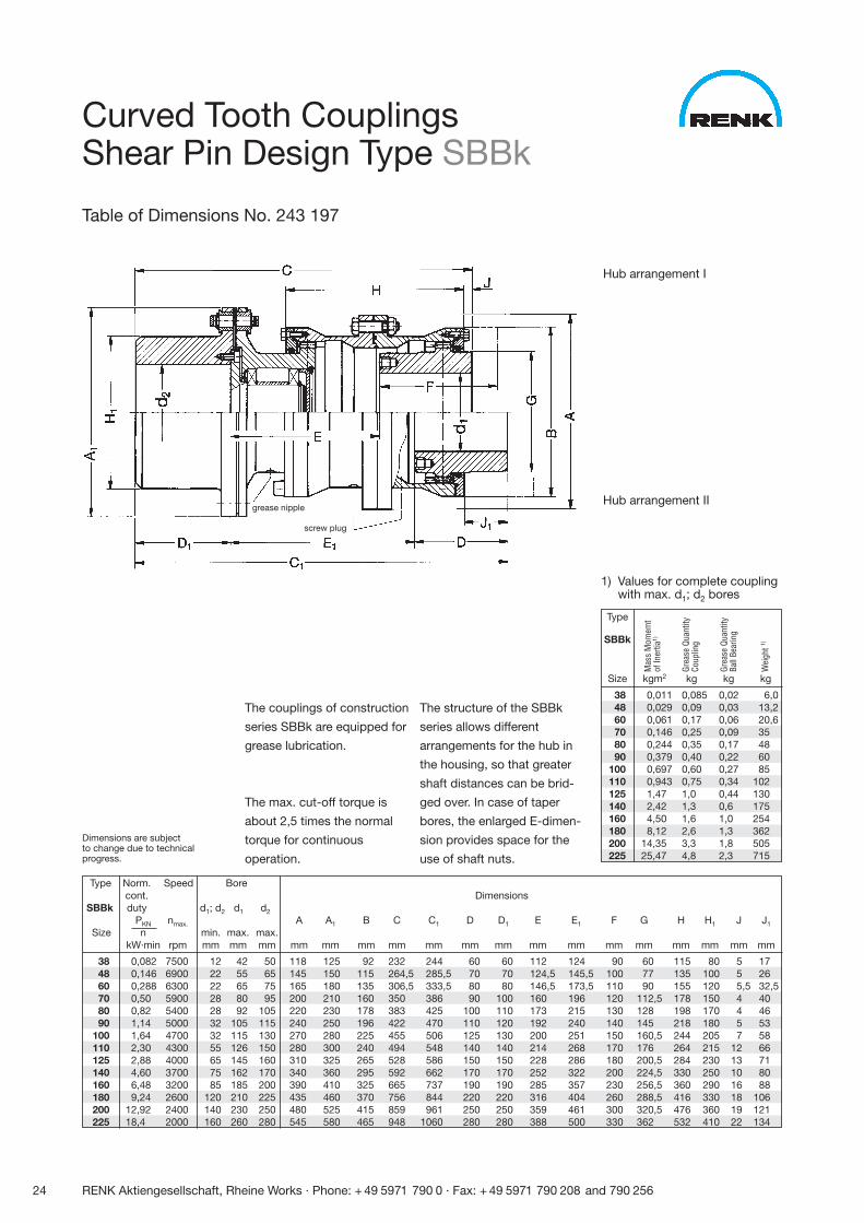
Curved Tooth CouplingsShear Pin Design Type SBBk
Table of Dimensions No. 243 197
grease nipple
screw plug
The couplings of construction
series SBBk are equipped for
grease lubrication.
The max. cut-off torque is
about 2,5 times the normal
torque for continuous
operation.
The structure of the SBBk
series allows different
arrangements for the hub in
the housing, so that greater
shaft distances can be brid-
ged over. In case of taper
bores, the enlarged E-dimen-
sion provides space for the
use of shaft nuts.
Dimensions are subjectto change due to technicalprogress.
Type Norm. Speed Borecont. Dimensions
SBBk duty d1; d2 d1 d2
PKN nmax. A A1 B C C1 D D1 E E1 F G H H1 J J1
Size n min. max. max.kW·min rpm mm mm mm mm mm mm mm mm mm mm mm mm mm mm mm mm mm mm
38 0,082 7500 12 42 50 118 125 92 232 244 60 60 112 124 90 60 115 80 5 1748 0,146 6900 22 55 65 145 150 115 264,5 285,5 70 70 124,5 145,5 100 77 135 100 5 2660 0,288 6300 22 65 75 165 180 135 306,5 333,5 80 80 146,5 173,5 110 90 155 120 5,5 32,570 0,50 5900 28 80 95 200 210 160 350 386 90 100 160 196 120 112,5 178 150 4 4080 0,82 5400 28 92 105 220 230 178 383 425 100 110 173 215 130 128 198 170 4 4690 1,14 5000 32 105 115 240 250 196 422 470 110 120 192 240 140 145 218 180 5 53
100 1,64 4700 32 115 130 270 280 225 455 506 125 130 200 251 150 160,5 244 205 7 58110 2,30 4300 55 126 150 280 300 240 494 548 140 140 214 268 170 176 264 215 12 66125 2,88 4000 65 145 160 310 325 265 528 586 150 150 228 286 180 200,5 284 230 13 71140 4,60 3700 75 162 170 340 360 295 592 662 170 170 252 322 200 224,5 330 250 10 80160 6,48 3200 85 185 200 390 410 325 665 737 190 190 285 357 230 256,5 360 290 16 88180 9,24 2600 120 210 225 435 460 370 756 844 220 220 316 404 260 288,5 416 330 18 106200 12,92 2400 140 230 250 480 525 415 859 961 250 250 359 461 300 320,5 476 360 19 121225 18,4 2000 160 260 280 545 580 465 948 1060 280 280 388 500 330 362 532 410 22 134
RENK Aktiengesellschaft, Rheine Works · Phone: + 49 5971 790 0 · Fax: + 49 5971 790 208 and 790 256 25
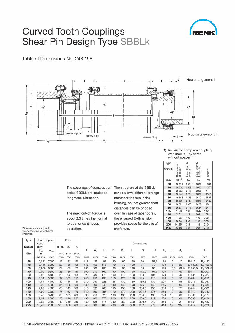
The couplings of construction
series SBBLk are equipped
for grease lubrication.
The max. cut-off torque is
about 2,5 times the normal
torque for continuous
operation.
The structure of the SBBLk
series allows different arrange-
ments for the hub in the
housing, so that greater shaft
distances can be bridged
over. In case of taper bores,
the enlarged E-dimension
provides space for the use of
shaft nuts.
Type Norm. Speed Borecont. Dimensions
SBBLk duty d1; d2 d1 d2
PKN nmax. A A1 B D D1 F G H H1
Size n min. max. max.kW·min rpm mm mm mm mm mm mm mm mm mm mm mm mm
38 0,082 7500 12 42 50 118 125 92 60 60 90 60 58,5 8048 0,146 6900 22 55 65 145 150 115 70 70 100 77 72 10060 0,288 6300 22 65 75 165 180 135 80 80 110 90 82 12070 0,50 5900 28 80 95 200 210 160 90 100 120 112,5 94,5 15080 0,82 5400 28 92 105 220 230 178 100 110 130 128 105 17090 1,14 5000 32 105 115 240 250 196 110 120 140 145 115 180
100 1,64 4700 32 115 130 270 280 225 125 130 150 160,5 130 205110 2,30 4300 55 126 150 280 300 240 140 140 170 176 140 215125 2,88 4000 65 145 160 310 325 265 150 150 180 200,5 150 230140 4,60 3700 75 162 170 340 360 295 170 170 200 224,5 175 250160 6,48 3200 85 185 200 390 410 325 190 190 230 256,5 190 290180 9,24 2600 120 210 225 435 460 370 220 220 260 288,5 219 330200 12,92 2400 140 230 250 480 525 415 250 250 300 320,5 249 360225 18,40 2000 160 260 280 545 580 465 280 280 330 362 279 410
J J1 L L
mm mm mm mm
5 17 E-115 E1-1275 26 E-132,5 E1-153,55,5 32,5 E-155,5 E1-182,54 40 E-171 E1-2074 46 E-185 E1-2275 53 E-204 E1-2527 58 E-216 E1-267
12 66 E-230 E1-28413 71 E-244 E1-30210 80 E-272 E1-34216 88 E-305 E1-37718 106 E-338 E1-42619 121 E-381 E1-48322 134 E-414 E1-526
Hub arrangement I
Hub arrangement II
1) Values for complete couplingwith max. d1; d2 boreswithout spacer
Type
SBBLk
Size kgm2 kg kg kg
38 0,011 0,085 0,02 6,048 0,030 0,09 0,03 13,760 0,062 0,17 0,06 21,170 0,148 0,25 0,09 35,780 0,248 0,35 0,17 48,590 0,39 0,40 0,22 61,5
100 0,72 0,60 0,27 88110 0,97 0,75 0,34 104125 1,50 1,0 0,44 132140 2,71 1,3 0,6 178160 4,56 1,6 1,0 258180 8,34 2,6 1,3 370200 14,65 3,3 1,8 510225 25,48 4,8 2,3 710Dimensions are subject
to change due to technicalprogress.
Mas
s M
omem
tof
Iner
tia1)
Grea
se Q
uant
ityCo
uplin
g
Grea
se Q
uant
ityBa
ll Be
arin
g
Wei
ght 1)
Curved Tooth Couplings Shear Pin Design Type SBBLk
Table of Dimensions No. 243 198
grease nipplescrew plug screw plug
26 RENK Aktiengesellschaft, Rheine Works · Phone: + 49 5971 790 0 · Fax: + 49 5971 790 208 and 790 256
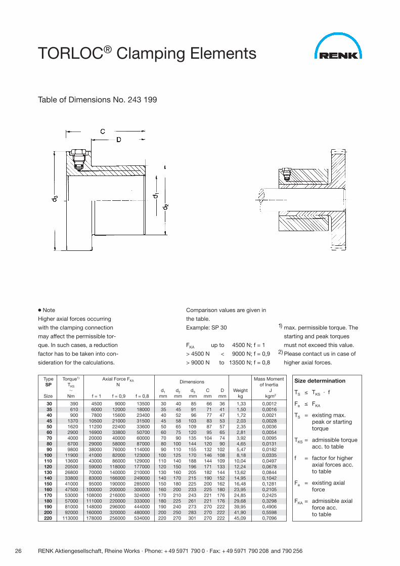
● Note
Higher axial forces occurring
with the clamping connection
may affect the permissible tor-
que. In such cases, a reduction
factor has to be taken into con-
sideration for the calculations.
Comparison values are given in
the table.
Example: SP 30
FKA up to 4500 N; f = 1,0
> 4500 N < 9000 N; f = 0,9
> 9000 N to 13500 N; f = 0,8
1) max. permissible torque. The
starting and peak torques
must not exceed this value.2) Please contact us in case of
higher axial forces.
Type Torque1) Axial Force FKA Mass MomentSP TKS N
Dimensions of Inertia
� d1 d2 d3 C D Weight JSize Nm f = 1 f = 0,9 f = 0,8 mm mm mm mm mm kg kgm2
30 390 4500 9000 13500 30 40 85 66 36 1,33 0,001235 610 6000 12000 18000 35 45 91 71 41 1,50 0,001640 900 7800 15600 23400 40 52 96 77 47 1,72 0,002145 1370 10500 21000 31500 45 58 103 83 53 2,03 0,002850 1620 11200 22400 33600 50 65 109 87 57 2,35 0,003660 2900 16900 33800 50700 60 75 120 95 65 2,81 0,005470 4000 20000 40000 60000 70 90 135 104 74 3,92 0,009580 6700 29000 58000 87000 80 100 144 120 90 4,65 0,013190 9800 38000 76000 114000 90 110 155 132 102 5,47 0,0182
100 11900 41000 82000 123000 100 125 170 146 108 8,18 0,0335110 13600 43000 86000 129000 110 140 188 144 109 10,04 0,0497120 20500 59000 118000 177000 120 150 196 171 133 12,24 0,0678130 26800 70000 140000 210000 130 160 205 182 144 13,62 0,0844140 33800 83000 166000 249000 140 170 215 190 152 14,95 0,1042150 41000 95000 190000 285000 150 180 225 200 162 16,48 0,1281160 47500 100000 200000 300000 160 200 233 225 180 23,95 0,2105170 53000 108000 216000 324000 170 210 243 221 176 24,85 0,2425180 57000 111000 220000 333000 180 225 261 221 176 29,68 0,3298190 81000 148000 296000 444000 190 240 273 270 222 39,95 0,4906200 92000 160000 320000 480000 200 250 283 270 222 41,90 0,5598220 113000 178000 256000 534000 220 270 301 270 222 45,09 0,7096
Size determination
TS ≤ TKS · f
Fa ≤ FKA
TS = existing max. peak or starting torque
TKS = admissible torqueacc. to table
f = factor for higheraxial forces acc.to table
Fa = existing axial force
FKA = admissible axialforce acc. to table
TORLOC® Clamping Elements
Table of Dimensions No. 243 199
RENK Aktiengesellschaft, Rheine Works · Phone: + 49 5971 790 0 · Fax: + 49 5971 790 208 and 790 256 27
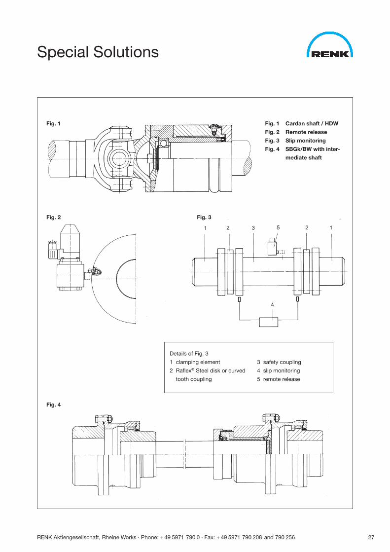
Special Solutions
Fig. 1
Fig. 2
Fig. 4
Fig. 3
Fig. 1 Cardan shaft / HDW
Fig. 2 Remote release
Fig. 3 Slip monitoring
Fig. 4 SBGk/BW with inter-
mediate shaft
Details of Fig. 3
1 clamping element
2 Raflex® Steel disk or curved
tooth coupling
3 safety coupling
4 slip monitoring
5 remote release
28 RENK Aktiengesellschaft, Rheine Works · Phone: + 49 5971 790 0 · Fax: + 49 5971 790 208 and 790 256
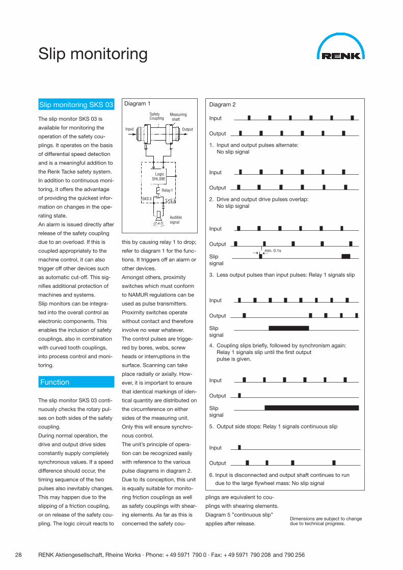
Slip monitoring
Slip monitoring SKS 03
The slip monitor SKS 03 is
available for monitoring the
operation of the safety cou-
plings. It operates on the basis
of differential speed detection
and is a meaningful addition to
the Renk Tacke safety system.
In addition to continuous moni-
toring, it offers the advantage
of providing the quickest infor-
mation on changes in the ope-
rating state.
An alarm is issued directly after
release of the safety coupling
due to an overload. If this is
coupled appropriately to the
machine control, it can also
trigger off other devices such
as automatic cut-off. This sig-
nifies additional protection of
machines and systems.
Slip monitors can be integra-
ted into the overall control as
electronic components. This
enables the inclusion of safety
couplings, also in combination
with curved tooth couplings,
into process control and moni-
toring.
Function
The slip monitor SKS 03 conti-
nuously checks the rotary pul-
ses on both sides of the safety
coupling.
During normal operation, the
drive and output drive sides
constantly supply completely
synchronous values. If a speed
difference should occur, the
timing sequence of the two
pulses also inevitably changes.
This may happen due to the
slipping of a friction coupling,
or on release of the safety cou-
pling. The logic circuit reacts to
this by causing relay 1 to drop;
refer to diagram 1 for the func-
tions. It triggers off an alarm or
other devices.
Amongst others, proximity
switches which must conform
to NAMUR regulations can be
used as pulse transmitters.
Proximity switches operate
without contact and therefore
involve no wear whatever.
The control pulses are trigge-
red by bores, webs, screw
heads or interruptions in the
surface. Scanning can take
place radially or axially. How-
ever, it is important to ensure
that identical markings of iden-
tical quantity are distributed on
the circumference on either
sides of the measuring unit.
Only this will ensure synchro-
nous control.
The unit’s principle of opera-
tion can be recognized easily
with reference to the various
pulse diagrams in diagram 2.
Due to its conception, this unit
is equally suitable for monito-
ring friction couplings as well
as safety couplings with shear-
ing elements. As far as this is
concerned the safety cou-Dimensions are subject to changedue to technical progress.
Audible signal
SafetyCoupling
Input
Measuringshaft
Output
LogicSHL09E
Relay1
SKS 3
Diagram 1
plings are equivalent to cou-
plings with shearing elements.
Diagram 5 ”continuous slip”
applies after release.
Diagram 2
Input
Output
1. Input and output pulses alternate:No slip signal
Input
Output
2. Drive and output drive pulses overlap:No slip signal
Input
Output
Slipsignal
3. Less output pulses than input pulses: Relay 1 signals slip
Input
Output
Slipsignal
4. Coupling slips briefly, followed by synchronism again:Relay 1 signals slip until the first outputpulse is given.
Input
Output
6. Input is disconnected and output shaft continues to run
due to the large flywheel mass: No slip signal
Input
Output
Slipsignal
5. Output side stops: Relay 1 signals continuous slip
�� min. 0.1s
RENK Aktiengesellschaft, Rheine Works · Phone: + 49 5971 790 0 · Fax: + 49 5971 790 208 and 790 256 29
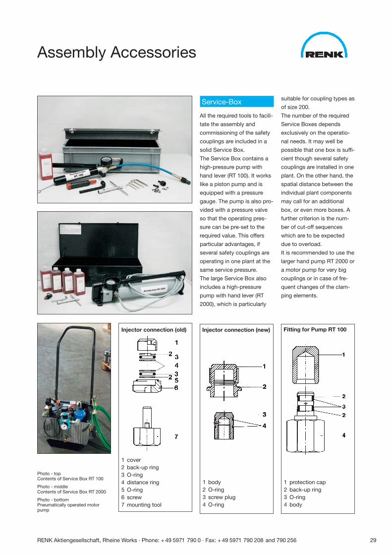
Assembly Accessories
Service-Box
All the required tools to facili-
tate the assembly and
commissioning of the safety
couplings are included in a
solid Service Box.
The Service Box contains a
high-pressure pump with
hand lever (RT 100). It works
like a piston pump and is
equipped with a pressure
gauge. The pump is also pro-
vided with a pressure valve
so that the operating pres-
sure can be pre-set to the
required value. This offers
particular advantages, if
several safety couplings are
operating in one plant at the
same service pressure.
The large Service Box also
includes a high-pressure
pump with hand lever (RT
2000), which is particularly
suitable for coupling types as
of size 200.
The number of the required
Service Boxes depends
exclusively on the operatio-
nal needs. It may well be
possible that one box is suffi-
cient though several safety
couplings are installed in one
plant. On the other hand, the
spatial distance between the
individual plant components
may call for an additional
box, or even more boxes. A
further criterion is the num-
ber of cut-off sequences
which are to be expected
due to overload.
It is recommended to use the
larger hand pump RT 2000 or
a motor pump for very big
couplings or in case of fre-
quent changes of the clam-
ping elements.
Injector connection (old) Injector connection (new) Fitting for Pump RT 100
1 cover2 back-up ring3 O-ring4 distance ring5 O-ring6 screw7 mounting tool
1 body2 O-ring3 screw plug4 O-ring
1 protection cap2 back-up ring3 O-ring4 body
Photo - topContents of Service Box RT 100
Photo - middleContents of Service Box RT 2000
Photo - bottomPneumatically operated motorpump
30 RENK Aktiengesellschaft, Rheine Works · Phone: + 49 5971 790 0 · Fax: + 49 5971 790 208 and 790 256
Applications
For Test Stands
Car manufacturers use HYGUARD® Safety Couplings in their
gearbox test stands. Due to the rapid and safe decoupling of
the gearbox in the event of cut-off, this safety coupling has
proved itself as an extremely effective protection for the
valuable measuring facilities. The test equipment consists of
an electric motor, an electric brake and the gearbox to be
tested. The measuring equipment is integrated in the test set-
up. The units to be tested are started up to the individual gear
speeds with gradually increasing load.
In case of failures, the gearbox has to be immediately dis-
connected from the motor to avoid all further damages. The
precise cause for the failure can only be determined in this way.
Due to the high speeds involved, only safety couplings with
roller bearings are used in such installations.
Technical details:
Safety coupling HWF 90 / Release torque 7.000 Nm
Speed 4.000 rpm / Shaft diameter 90 mm
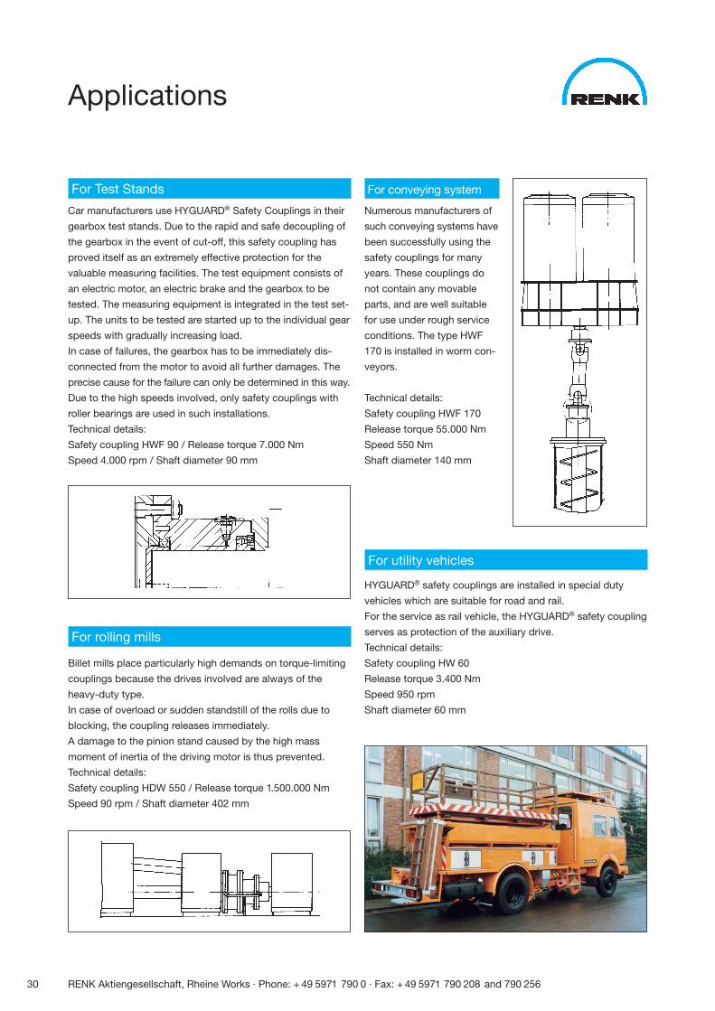
For conveying system
Numerous manufacturers of
such conveying systems have
been successfully using the
safety couplings for many
years. These couplings do
not contain any movable
parts, and are well suitable
for use under rough service
conditions. The type HWF
170 is installed in worm con-
veyors.
Technical details:
Safety coupling HWF 170
Release torque 55.000 Nm
Speed 550 Nm
Shaft diameter 140 mm
For utility vehicles
HYGUARD® safety couplings are installed in special duty
vehicles which are suitable for road and rail.
For the service as rail vehicle, the HYGUARD® safety coupling
serves as protection of the auxiliary drive.
Technical details:
Safety coupling HW 60
Release torque 3.400 Nm
Speed 950 rpm
Shaft diameter 60 mm
For rolling mills
Billet mills place particularly high demands on torque-limiting
couplings because the drives involved are always of the
heavy-duty type.
In case of overload or sudden standstill of the rolls due to
blocking, the coupling releases immediately.
A damage to the pinion stand caused by the high mass
moment of inertia of the driving motor is thus prevented.
Technical details:
Safety coupling HDW 550 / Release torque 1.500.000 Nm
Speed 90 rpm / Shaft diameter 402 mm
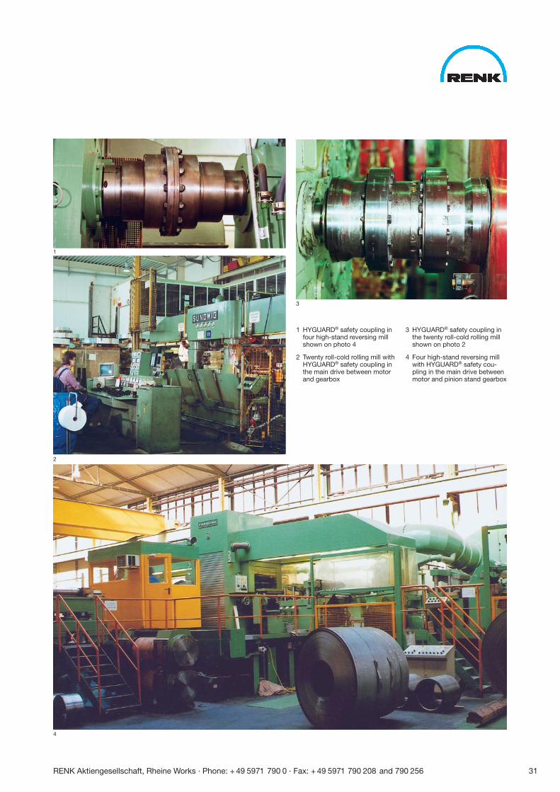
1 HYGUARD® safety coupling infour high-stand reversing millshown on photo 4
2 Twenty roll-cold rolling mill with HYGUARD® safety coupling inthe main drive between motorand gearbox
3 HYGUARD® safety coupling inthe twenty roll-cold rolling millshown on photo 2
4 Four high-stand reversing millwith HYGUARD® safety cou-pling in the main drive betweenmotor and pinion stand gearbox
1
2
3
4
RENK Aktiengesellschaft, Rheine Works · Phone: + 49 5971 790 0 · Fax: + 49 5971 790 208 and 790 256 31
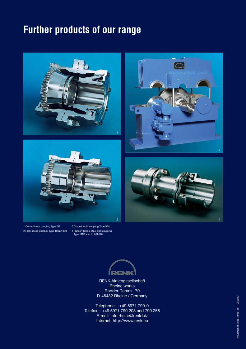
Further products of our range
1 Curved tooth coupling Type SB
2 High-speed gearbox Type THGD-900
3 Curved tooth coupling Type SBk
4 Raflex® flexible steel disk coupling Type MTP acc. to API 610
RENK Aktiengesellschaft Rheine works
Rodder Damm 170 D-48432 Rheine / Germany
Telephone: ++49 5971 790-0 Telefax: ++49 5971 790 208 and 790 256
E-mail: [email protected] Internet: http://www.renk.eu
1
2 4
3
Neu
dru
ck R
R 0
68/1
1.08
-3e
· 0
8209
0