Hydrophilic modification of SLA 3D printed droplet ...
9
Hydrophilic modification of SLA 3D printed droplet generators by photochemical grafting† Tristan W. Bacha, Dylan C. Manuguerra, Robert A. Marano and Joseph F. Stanzione III * Few droplet generators manufactured using desktop stereolithography 3D printers have been reported in the literature. Moreover, 3D printed microfluidic chips are typically hydrophobic, limiting their application to water in oil droplets. Herein, we present designs for concentric and planar 3D printed microfluidic devices suitable for making polymeric microparticles using an off-the-shelf commercial stereolithography printer and resin. The devices consist of a microscope slide, binder clips, and printed components. Channels were modified by an ultraviolet grafting of methacrylic acid to the surface of chips, yielding a hydrophilic coating without modification to the bulk polymer. The water contact angle decreased from 97.0 to 25.4 after grafting. The presence of the coating was confirmed by microscopy and spectroscopy techniques. Polystyrene microparticles in the <100 mm size range were generated with varying molecular weights using the described microfluidic chips. Our work provides a facile method to construct droplet generators from commercial stereolithography printers and resins, and a rapid surface modification technique that has been under-utilized in 3D printed microfluidics. A wide range of microfluidic devices for other applications can be engineered using the methods described. Introduction Classic methods of manufacturing microuidic devices are cumbersome, requiring many steps and highly specialized equipment. Photolithography is a common method to make micro-scale moulds for casting PDMS microuidic devices. 1 The cost and complexity of photolithography makes it impractical for new laboratories, or researchers looking to easily incorpo- rate microuidics into a part of their work. Milling microuidic devices and moulds is another option for device production, but this method requires a high precision CNC mill and replication techniques. 2 Although outsourcing micromachining or photo- lithography sources is possible, in-house techniques are preferred when a device may take several iterations to develop. 3D printing is an attractive solution for manufacturing microuidic chips because of the availability of affordable desktop printers. Recently, 3D printing has been utilized to create microuidic devices for healthcare, chemistry, and engineering applications. 3–5 3D printing is fast, simple, low cost, and can produce 3D structured polymer microchips that are resistant to swelling in solvents. 6–8 PDMS is known to swell in many organic solvents, which limits its application in micro- uidics. Swelling is of utmost concern in droplet generators because of the strong dependence of droplet formation on channel dimensions. Droplet generators have a broad range of uses spanning multiple elds including engineering, chemistry, biology, food, and medicine. 9–11 Because of the expansive applicability of droplet generators, simple and accessible methods of producing them are highly appealing to many research groups. Herein, we report the design, surface treatment, and assembly of simple and quick to produce oil in water (o/w) droplet generators utilizing an inexpensive commercial desktop 3D printer. Our design does not require a modied 3D printer or resin system and can produce polymer particles in the sub 100 mm size range with narrow size distributions. Furthermore, our methodology can be extended to enable rapid fabrication of uidic devices other than droplet generators. Recently, several 3D printed droplet generators have been reported using mostly stereolithography apparatus (SLA) or direct light projection (DLP) printers. Fused deposition modelling (FDM) is also used, but printable feature size is poor compared to SLA. 1,12 The reported droplet generator designs encompass 3D structures, 7,8,13–17 planar structures, and modular designs. 13,16 Other droplet generators utilize 3D printing for either device mould making, 18,19 or parts to make hybrid devices. 20–23 The hybrid devices utilize tubing, capillaries, or needles to facilitate droplet production. Purely 3D printed chips with the smallest feature sizes require custom 3D printers and resins. The smallest feature sizes are achieved using microstereolithography, 11 modied 3D Department of Chemical Engineering, Rowan University, 201 Mullica Hill Rd, Glassboro, NJ 08028, USA. E-mail: [email protected] † Electronic supplementary information (ESI) available. See DOI: 10.1039/d1ra03057d Cite this: RSC Adv. , 2021, 11, 21745 Received 19th April 2021 Accepted 5th June 2021 DOI: 10.1039/d1ra03057d rsc.li/rsc-advances © 2021 The Author(s). Published by the Royal Society of Chemistry RSC Adv., 2021, 11, 21745–21753 | 21745 RSC Advances PAPER Open Access Article. Published on 18 June 2021. Downloaded on 3/21/2022 4:28:25 PM. This article is licensed under a Creative Commons Attribution-NonCommercial 3.0 Unported Licence. View Article Online View Journal | View Issue
Transcript of Hydrophilic modification of SLA 3D printed droplet ...

RSC Advances
PAPER
Ope
n A
cces
s A
rtic
le. P
ublis
hed
on 1
8 Ju
ne 2
021.
Dow
nloa
ded
on 3
/21/
2022
4:2
8:25
PM
. T
his
artic
le is
lice
nsed
und
er a
Cre
ativ
e C
omm
ons
Attr
ibut
ion-
Non
Com
mer
cial
3.0
Unp
orte
d L
icen
ce.
View Article OnlineView Journal | View Issue
Hydrophilic mod
Department of Chemical Engineering, Ro
Glassboro, NJ 08028, USA. E-mail: stanzion
† Electronic supplementary informa10.1039/d1ra03057d
Cite this: RSC Adv., 2021, 11, 21745
Received 19th April 2021Accepted 5th June 2021
DOI: 10.1039/d1ra03057d
rsc.li/rsc-advances
© 2021 The Author(s). Published by
ification of SLA 3D printed dropletgenerators by photochemical grafting†
Tristan W. Bacha, Dylan C. Manuguerra, Robert A. Marano and Joseph F. StanzioneIII*
Few droplet generators manufactured using desktop stereolithography 3D printers have been reported in
the literature. Moreover, 3D printed microfluidic chips are typically hydrophobic, limiting their application
to water in oil droplets. Herein, we present designs for concentric and planar 3D printed microfluidic
devices suitable for making polymeric microparticles using an off-the-shelf commercial
stereolithography printer and resin. The devices consist of a microscope slide, binder clips, and printed
components. Channels were modified by an ultraviolet grafting of methacrylic acid to the surface of
chips, yielding a hydrophilic coating without modification to the bulk polymer. The water contact angle
decreased from 97.0� to 25.4� after grafting. The presence of the coating was confirmed by microscopy
and spectroscopy techniques. Polystyrene microparticles in the <100 mm size range were generated with
varying molecular weights using the described microfluidic chips. Our work provides a facile method to
construct droplet generators from commercial stereolithography printers and resins, and a rapid surface
modification technique that has been under-utilized in 3D printed microfluidics. A wide range of
microfluidic devices for other applications can be engineered using the methods described.
Introduction
Classic methods of manufacturing microuidic devices arecumbersome, requiring many steps and highly specializedequipment. Photolithography is a common method to makemicro-scale moulds for casting PDMSmicrouidic devices.1 Thecost and complexity of photolithography makes it impracticalfor new laboratories, or researchers looking to easily incorpo-rate microuidics into a part of their work. Milling microuidicdevices andmoulds is another option for device production, butthis method requires a high precision CNC mill and replicationtechniques.2 Although outsourcing micromachining or photo-lithography sources is possible, in-house techniques arepreferred when a device may take several iterations to develop.
3D printing is an attractive solution for manufacturingmicrouidic chips because of the availability of affordabledesktop printers. Recently, 3D printing has been utilized tocreate microuidic devices for healthcare, chemistry, andengineering applications.3–5 3D printing is fast, simple, low cost,and can produce 3D structured polymer microchips that areresistant to swelling in solvents.6–8 PDMS is known to swell inmany organic solvents, which limits its application in micro-uidics. Swelling is of utmost concern in droplet generators
wan University, 201 Mullica Hill Rd,
tion (ESI) available. See DOI:
the Royal Society of Chemistry
because of the strong dependence of droplet formation onchannel dimensions.
Droplet generators have a broad range of uses spanningmultiple elds including engineering, chemistry, biology, food,and medicine.9–11 Because of the expansive applicability ofdroplet generators, simple and accessible methods ofproducing them are highly appealing to many research groups.Herein, we report the design, surface treatment, and assemblyof simple and quick to produce oil in water (o/w) dropletgenerators utilizing an inexpensive commercial desktop 3Dprinter. Our design does not require a modied 3D printer orresin system and can produce polymer particles in the sub 100mm size range with narrow size distributions. Furthermore, ourmethodology can be extended to enable rapid fabrication ofuidic devices other than droplet generators.
Recently, several 3D printed droplet generators have beenreported using mostly stereolithography apparatus (SLA) ordirect light projection (DLP) printers. Fused depositionmodelling (FDM) is also used, but printable feature size is poorcompared to SLA.1,12 The reported droplet generator designsencompass 3D structures,7,8,13–17 planar structures, and modulardesigns.13,16 Other droplet generators utilize 3D printing foreither device mould making,18,19 or parts to make hybriddevices.20–23 The hybrid devices utilize tubing, capillaries, orneedles to facilitate droplet production.
Purely 3D printed chips with the smallest feature sizesrequire custom 3D printers and resins. The smallest featuresizes are achieved using microstereolithography,11 modied 3D
RSC Adv., 2021, 11, 21745–21753 | 21745

RSC Advances Paper
Ope
n A
cces
s A
rtic
le. P
ublis
hed
on 1
8 Ju
ne 2
021.
Dow
nloa
ded
on 3
/21/
2022
4:2
8:25
PM
. T
his
artic
le is
lice
nsed
und
er a
Cre
ativ
e C
omm
ons
Attr
ibut
ion-
Non
Com
mer
cial
3.0
Unp
orte
d L
icen
ce.
View Article Online
printers and resins,24 and high-end or custom 3Dprinters.14,16,25,26 Channel sizes down to 18 � 20 mm have beenreported with custom setups.25 Smaller channel sizes are moredifficult to obtain with commercial desktop printers. Thesechannels are typically on the order of several hundred micronsin size.7,8,13,15,17,27
To produce droplets, the dispersant should wet the devicepreferentially to the dispersed phase. Only several methods ofhydrophilic surface modication have been reported for SLAprinted parts. Kanai and Tsuchiya designed and 3D printeda double emulsion generator.14 They treated the walls of thedevice to be hydrophilic by applying a hydrolyzed ethyl silicatesolution to the channels. The device was subsequently heated to120 �C to vaporize the solvent and cure the coating.28 Brandhoffet al. made parts printed on an SLA printer hydrophilic byultraviolet (UV) graing.29 They showed improved hydrophi-licity of printed parts with the technique; however, the appli-cability of this method to droplet generators was notdemonstrated. Ji et al. noted treatment of different 3D printedcomponents of their modular devices but did not specify theexact method to achieve hydrophilic coatings.13 Wang et al.incorporated a vinyl terminated initiator into a UV curable resinthat enabled surface functionalization aer printing.30 Thismethod is versatile and effective for creating modied surfaces;however, it requires modication of the bulk resin in order tofacilitate an atom transfer radical polymerization reactionlimited to the surface.
The surface properties of thiol–ene and PDMS devices madeby so lithography replication techniques have been modiedusing UV graing.31–33 The resin formulation adjustments thatfacilitate UV graing require components to be mixed in an off-stoichiometry fashion, such that an excess of specic functionalgroups remain unreacted in the replication process. Althoughunreacted groups enable graing, the resulting polymer is notcrosslinked as effectively as a stoichiometric formulation. Theresulting elastomeric materials are more susceptible to swellingthan a crosslinked thermoset with a high elastic modulus.34
Thus, surface treatment without modication of the bulk resinsystem is desirable. Abate and colleagues used UV graing tomake specic regions of PDMS devices hydrophilic.35 They rstdeposited a photoreactive sol–gel coating onto their device,then lled channels with an acrylic acid monomer solutionbefore exposing the system to UV light. They showed that highlyspatially selective UV modication can be achieved with a reso-lution of about 5 mm. Gonzalez et al. functionalized PDMS baseddevices using a UV graing technique.36 They utilized unreactedfunctional groups on the chip surfaces to achieve graing.
Few reports of 3D printed droplet generators demonstrate o/w droplet generation owing to few established surface modi-cation methods. Morimoto et al. reported axisymmetric owfocusing devices that produced both oil in water and water in oilemulsions without surface modication.16,17 Zhang et al. re-ported a nonplanar design that achieved a similar result.15
Later, they also reported a co-ow design that did not requiresurface treatment.11 Although concentric 3D designs canproduce oil in water emulsions, the surface is still vulnerable towetting by the organic phase if the solutions are not strategically
21746 | RSC Adv., 2021, 11, 21745–21753
loaded into the device, or there is a disturbance in the ow. Ifwetting occurs, the device will either no longer produce drop-lets, or the size or size distribution may vary from the expectedvalue. Therefore, a generator benets substantially from havingproper surface properties for the uids handled.
Herein, we present a method for making 3D printed dropletgenerators for producing both oil in water (o/w) and water in oil(w/o) emulsions. The designs are printed using a commerciallyavailable SLA printer and resin system that is rigid when curedand resistant to swelling in the uids studied. The open-channel design enables photograing of hydrophilic mono-mer to the channel surface, and can be printed withouta custom 3D printer or resin.24 Photograing and assemblysteps only require a UV light source, inert gas, and somecommon lab supplies. Our method does not rely on the pres-ence of unreacted functional groups or additives to the resin,and can be performed aer parts have been fully post-curedwith UV light. The graing method is described in depth byTretinnikov et al.37 In the proposed mechanism, an initiator(benzophenone) absorbs UV light and is excited to a nal tripletstate (3In*). The excited initiator abstracts a hydrogen atomfrom a polymer backbone (i.e., the microuidic devices herein),yielding a radical site on the polymer (Pc) that can initiategraing.
3In* + PH / cInH + Pc (1)
Pc then reacts with monomer (methacrylic acid) in solution.
Pc + M / PMc (2)
The reaction propagates, achieving a nal length of (n)monomer molecules plus one with a free radical site (Mc)susceptible to termination.
PMc + nM / PMnMc (3)
This scheme assumes the lack of oxygen in solution, whichhas a severe limiting effect on the free radical reaction.37
Along with the graing technique, the simplicity of thedesign and assembly method enables rapid manufacture/assembly in a workday, and disassembly within seconds forcleaning. Moreover, the device assembly method permitsunobstructed viewing of the droplet generation process,a shortcoming in other reported designs.7,14–17,23 We demon-strate the operation of our device by producing a range ofmicroparticles from o/w droplets of several polystyrenes dis-solved in butyl acetate and ethyl acetate.
Methods and materialsDevice fabrication
Printing. Microuidic chips were designed in SOLIDWORKSand printed on a Form 2 3D printer (Formlabs, Inc.). STL les ofthe designs are provided as ESI.† The planar droplet generatorwas printed with Formlabs High Temperature V1 resin, and thelayer thickness was set to 25 mm. The top surface was rotated 15�
around both axes parallel to the surface. Additional information
© 2021 The Author(s). Published by the Royal Society of Chemistry

Paper RSC Advances
Ope
n A
cces
s A
rtic
le. P
ublis
hed
on 1
8 Ju
ne 2
021.
Dow
nloa
ded
on 3
/21/
2022
4:2
8:25
PM
. T
his
artic
le is
lice
nsed
und
er a
Cre
ativ
e C
omm
ons
Attr
ibut
ion-
Non
Com
mer
cial
3.0
Unp
orte
d L
icen
ce.
View Article Online
on the choice of print angle is in the ESI (Fig. S1).† Theconcentric device pieces were printed with Formlabs HighTemperature V2 resin at 100 mm layer thickness. The top face ofthe print was parallel with the resin vat. Fig. 1 depicts the printorientation of each part and the support material used. Beforeeach print, the printer and resin vat were inspected forcontaminants. Dust was removed from the printer usingcompressed air, and contaminants were removed from the resinvat with a pipette. Printed parts were agitated using a FormlabsFormWash isopropanol (99.5%, VWR Chemicals BDH) bath for5 minutes, then thoroughly washed with clean isopropanol toremove all uncured resin. Concentric devices were placed ina beaker with isopropanol and sonicated in a water bath(Branson model 1510) for 5 minutes to ensure all resin wasremoved from the orices. The parts were dried withcompressed air and post cured in a Formlabs Form Cure for 30minutes at 60 �C.
Device preparation and graing. The 3D printed parts wereprepared for graing by wet sanding with clean 1000 gritsandpaper just until the layer lines from 3D printing wereremoved. The same surface was then polished using a cleanpiece of 5000 grit paper. By sanding and polishing on a atsurface (e.g., a lab bench, glass plate), the atness was accept-able for nal assembly and appeared optically clear.
The graing solution comprised 2 M methacrylic acid (99%,Sigma-Aldrich) and 0.01 M benzophenone (Ward's Science) in90% v/v deionized (DI) water in ethanol (Absolute, Pharmco)solvent. DI water was obtained from a Milli-Q® pure watersystem. The graing solution composition was adapted from Liet al.38 This solution was transferred into a vial and vigorouslysparged with argon (99.999%, Airgas®) for 30 minutes beforeuse. No appreciable volume loss of solution was noted. Thepolished 3D printed parts were placed in a glass Petri dish andcovered with graing solution to 5 mm above the surface. Theopen channels on the planar device and orices on theconcentric device were oriented towards the UV source. ThePetri dish was placed into a polyethylene bag, and the systemwas ventilated with argon for 30 seconds. These steps were donerapidly to ensure minimal oxygenation of the solution. The
Fig. 1 Representation of the chip designs as printed on supportstructures for (a) planar device, (b) inlet section of concentric device,and (c) exit section of concentric device.
© 2021 The Author(s). Published by the Royal Society of Chemistry
parts in inert solution were irradiated for 10 minutes with 90mW cm�2 of unltered UV light from an Omnicure S2000 lightsource. Aer graing, the parts were washed with DI water andstirred in acetone for 1 hour. They were rinsed again and placedin a beaker with DI water. Parts for spectroscopy analysis wereswirled in DI water for two days on a shaker plate.
Chip assembly. Aer washing, 1/1600 uoropolymer tubingwas pressed into ports on the devices. With careful tuning of thehole diameter, tubing can be placed without glue. We applieda small amount of fast curing epoxy to the base of the tubingaer insertion to prevent the tubes from dislodging fromrepeated use and storage. The planar chips were assembled byclamping the polished channel surface directly to a hydrophilicmicroscope slide (IHC Microscope Slides, Springside Scientic)with off-the-shelf binder clips. The polished contacting halvesof the concentric devices were clamped together with M3 bolts.The bolts were tightened while pressing the open-face channelsurfaces onto a glass slide to ensure atness. Aer this step,light standing was possible if necessary to adjust the atness ofthe channel surfaces that were clamped to the microscope slide.For both devices, microscope slides were prepared by rinsingwith DI water and blowing dry with compressed air to removedust. Trapped dust and bers caused visible leakage around theedges of the devices if not cleaned beforehand.
Droplet production
Polymer solutions. The aqueous phase was prepared bydissolving 72 000 Da polyvinyl alcohol (PVA) (87.0–89.0%hydrolyzed, MP Biomedicals, LLC) in DI water at 80 �C for 2hours. The solution was diluted to a nal concentration of 2%w/v. Solutions of polystyrene standards (polydispersity < 1.06)with molecular weights of 10, 19.8, and 97.2 kDa were preparedas the organic phase (Pressure Chemical Co.). A polydispersepolystyrene of approximately 210 kDa from Scientic PolymerProducts, Inc. (Cat #844) was also used. The polystyrenes weredissolved in butyl acetate (99%, TCI America, Inc.) and dilutedto 5%w/v in volumetric asks. A solution of 100 kDa polystyrenedissolved in ethyl acetate (99.5%, VWR Chemicals BDH®) wasalso prepared for use in the concentric device.
Device operation. Solutions were pumped through deviceswith NE-300 syringe pumps (New Era Pump Systems, Inc.).Droplets were collected into glass scintillation vials. The outlettubing from the device was placed at the bottom of the vial sothat the uid was in constant contact with a surface and therewas no dripping. Dripping, moving the tubing, or shaking thetable lead to visible disturbances in the ow. When changingowrates, the system was le for at least 3 minutes for the owto stabilize. Vials of droplets were le overnight in a fume hoodto evaporate and yield polystyrene microspheres.
Analysis techniques
Spectroscopy. Mid IR spectra of the graed and unmodiedsurfaces were taken on a Nicolet™ iS50 FTIR Spectrometer withan attenuated total reection attachment. 32 scans at a resolu-tion of 4 cm�1 were taken for each sample. Data were normal-ized with respect to the highest peak for each spectrum.
RSC Adv., 2021, 11, 21745–21753 | 21747

RSC Advances Paper
Ope
n A
cces
s A
rtic
le. P
ublis
hed
on 1
8 Ju
ne 2
021.
Dow
nloa
ded
on 3
/21/
2022
4:2
8:25
PM
. T
his
artic
le is
lice
nsed
und
er a
Cre
ativ
e C
omm
ons
Attr
ibut
ion-
Non
Com
mer
cial
3.0
Unp
orte
d L
icen
ce.
View Article Online
Contact angles. Contact angles were measured by the sessiledroplet method using an optical tensiometer (Biolin Scientic).10 mL droplets of DI water were manually dispensed on 3Dprinted parts using a micropipette. Measurements were taken30 s aer placing the drops on the part. The value reported is theaverage value measured during a 10 s window aer themeasurement was started. Angles were evaluated using thepolynomial tting method. Values reported are averages of atleast four experimental points.
Microscopy. A Nanoscience Instruments Phenom XL scan-ning electron microscope (SEM) was used to obtain all SEMmicrographs. An accelerating voltage of 5 kV and chamberpressure of 60 Pa were used. The samples were imaged withoutgold sputtering. Optical micrographs were taken witha Pixelink® PL-D759CU attached to a Zeiss Axiovert 40 micro-scope. Particle sizes were determined using the Image Pro-cessing Toolbox in MATLAB® from optical microscope images.The soware was calibrated using a stage micrometer slide.Sizes reported in the study are of the nal particle diameter. Aconversion equation to droplet diameter is given in the ESI(Section S2).†
Results and discussionSurface analysis
The wettability of unmodied and graed surfaces of polymerparts was examined by sessile contact angle experiments withwater droplets. Droplets had a contact angle of 97.0� � 6.7� onthe unmodied polymer surface, indicating a natively hydro-phobic surface (Fig. 2a). Droplets had a contact angle of 25.4� �4.0� on the modied surface and did not wet out completely;however, regions around the droplet wet out onto the surfaceinto small ridges of the 3D printed surface. Photographs of
Fig. 2 Representative photographs from the contact angle experi-ment of water droplets on an (a) unmodified 3D printed polymersurface and (b) on a surface modified by grafting methacrylic acid to it.(c) Butyl acetate (horizontal channel) o/w droplet formation in devicewith methacrylic acid grafted to the surface and (d) butyl acetatewetting the channel wall in an untreated chip.
21748 | RSC Adv., 2021, 11, 21745–21753
wetting behaviour on both surfaces are given in the ESI(Fig. S2).† The good water-wetting behavior was conrmed withow experiments with water and butyl acetate. Butyl acetatedroplets in DI water were easily formed with the gra-modiedchannels (Fig. 2c). In the unmodied device, butyl acetatewetted the channel walls and did not form any consistentdroplets (Fig. 2d). Note that the darker appearance of the graf-ted device is a result of the 10 minute UV exposure.
The presence of hydrophilic methacrylic acid groups on thesurface of graed polymer parts was conrmed by FTIR anal-ysis, shown in Fig. 3a. The 1690 cm�1 peak characteristic of themethacrylic acid monomer C]O stretch is apparent on thegraed surface, overshadowing some of the adjacent peaks onthe unmodied surface. A broad OH stretching from 2500–3300 cm�1 characteristic of the carboxylic acid group in meth-acrylic acid was also present on the part aer graing. A secondbump up to 3800 cm�1 extending from the carboxylic acid OHstretch indicates the graed layer is swelled with water. FTIRwas taken shortly aer the part was removed from DI water andblown dry with compressed air.
SEM imaging was also used to verify surface modication.Graed surfaces appeared smoother than the original unmod-ied surface. Fig. 3b shows the native polymer surfacemorphology without any treatment. The tendril-like features arerounded over in the graed sample, depicted in Fig. 3c. Thesurface used for both gures was the top portion of a 3D printedcoupon. For reference, the surfaces shown in Fig. 3b and c arethe surfaces that the droplets were placed on in Fig. S2a and b inthe ESI,† respectively.
Although the photograing method used is straightforwardand can be done within an hour, techniques without deaerationof the graing solution would eliminate the need for an inertgas cylinder, potentially making the technique more accessible.For example, Shuwen et al. modied a PDMS device witha graing solution without deaeration to render it hydrophilic.39
The method utilized NaIO4 to scavenge dissolved oxygen fromthe graing solution.40 Abate and colleagues used a similarmethod to selectively gra acrylic acid to a uorinated sol–gelcoating they coated a PDMS device with. Other graing tech-niques used higher powered light sources to avoid deaeratingthe graing solution.37,38,41 Tretinnikov et al. placed a quartzcover directly on their graing solution placed on the part,creating a very small volume of solution and simultaneouslypreventing continuous oxygen diffusion into it.37 The covereliminated the need for deoxygenation. This method was notpractical for the application herein because it relies on thinlms (on the order of tens of mm) of graing solution isolatedbetween a surface to be modied and an air-impenetrablequartz plate. With solution thicknesses above 100 mm, moreoxygen was present in the placed solution, and the graing yielddrastically decreased to zero. Thus, the deeper channels in thiswork would not be successfully modied by directly applyingthe methods of Tretinnikov et al.37 Amuch higher intensity light(such as in the method of Jang and Go) may eliminate the needfor deaeration, as the high-intensity light can overcome thenegative effects of oxygen inhibition on the free-radical graingmechanism.41 Our technique with deaeration of the graing
© 2021 The Author(s). Published by the Royal Society of Chemistry

Fig. 3 (a) FTIR spectra of the unmodified test coupon 3D printed with Formlabs High Temp V1 resin, the surface modified by photografting, andmethacrylic acid monomer used for graft modification. (b) The top surface of a 3D printed part without graft modification and (c) the part withmethacrylic acid monomer grafted to the surface.
Paper RSC Advances
Ope
n A
cces
s A
rtic
le. P
ublis
hed
on 1
8 Ju
ne 2
021.
Dow
nloa
ded
on 3
/21/
2022
4:2
8:25
PM
. T
his
artic
le is
lice
nsed
und
er a
Cre
ativ
e C
omm
ons
Attr
ibut
ion-
Non
Com
mer
cial
3.0
Unp
orte
d L
icen
ce.
View Article Online
solution produces enough surface wettability for our devicedesign and polymer choice, without the need for a higherpowered light source than used herein (90 mW cm�2). Anincrease in radiation time may ensure adequate graing if themethod is adapted with a less powerful light source.
It has been shown that compared to other hydrophilicmonomers, acrylic acid yields some of the most hydrophilicsurfaces.39 We chose to use methacrylic acid because of itshigher demonstrated graing efficiency than acrylic acid.38
Moreover, the wettability of these surfaces may be furtherimproved by treatment with NaOH.40 A range of other acrylateand methacrylate based monomer solutions could besubstituted for the one herein if desired.
Design considerations
Two droplet generator designs (planar and concentric) weredeveloped to be simple to assemble and print effectively on the3D printer. Multiple copies of both designs could be printedwithin several hours on the 3D printer. The open-face design ofthe planar device (Fig. 4a) allows resin to drain sufficiently fromthe channels while printing. Aer sanding down the surface toremove layer-lines from 3D printing and polishing, a micro-scope slide clamped to the surface with binder clips results ina seal without leakage during droplet generation. Slight leakagewas only observed around the edges of the device if uids wereforced through the devices. This leakage occurred during initiallling steps when ushing bubbles out of the devices,squeezing the syringes by hand. For the application herein, wedid not need a clamping mechanism more robust than thebinder clips. The syringe pumps stalled before any leakageoccurred during droplet generation. For researchers interestedin high pressure applications, an additional clamping xturethat can apply more pressure than a binder clip may benecessary.
The concentric device was printed in two halves to effectivelyprint the smallest features. Early prototypes were unsuccessfulas one-piece prints. The small orices printed successfully whenthey were parallel to the build direction. In this orientation,
© 2021 The Author(s). Published by the Royal Society of Chemistry
a one piece version of the design showed excessive distortion ofthe at face perpendicular to the orice. If the orices wereprinted parallel to the build surface, the channels closed.Printing of a one-piece device may be feasible with custom 3Dprinters, resins, or high-end machines; however, this was notpossible on the desktop printer with the current design. Thus,to enable 3D printing of small orices, the device was split intotwo pieces such that the at connecting portions were perfectlyat and perpendicular to the small orices of each half.
We found the best away to assemble the concentric device(Fig. 4d) was to sand the two faces that are clamped together,treat the device by graing, then clamp the device together.Then, the surface adjacent to the microscope slide was sandedaer graing to ensure the best contact. We did not need tosmooth the surfaces further, but methods are available ifneeded. For example, van der Linden and colleagues useda drop of 3D printing resin to ensure a good seal between theirdevices and a holding xture.24 They let the drop ll spacebetween the chip and cover plate, then subjected the assemblyto UV light.
The microscope slide assembly method yields a planardevice with unobstructed viewing of droplet generation.Viewing of droplets in the concentric device is possible, but the3D structure obscures some channels as they are surrounded bypolymer. However, droplets can still be viewed through thechannels. With good optical clarity of both devices, monitoringparticle production is simple with an inverted microscope. Inthe event of contamination in the solutions, foreign particlesdisrupting the ow are easily identied. If particles becometrapped in the channels or orices, the microscope slide cansimply be unclamped, and the channels purged to removedebris. Because of this feature, we did not nd lteringsolutions before use necessary for short-term experiments.Letting small particles settle from the polymer solutions anddrawing solutions from the top surface was sufficient for mostcases; however, ltering should be considered if using thedevices for long periods of time so droplet production isuninterrupted.
RSC Adv., 2021, 11, 21745–21753 | 21749

Fig. 4 (a) Planar device clipped to a microscope slide. (b) Design dimensions of the top edges of the channels. The channels were engraved fromthe top sketch to a depth of 300 mm with a draft angle of 10�. (c) Measured dimensions on the printed chip. (d) Concentric droplet generatorassembled prior to inserting tubing and clamping to amicroscope slide. (e) 3D rendering of the concentric device and dimensions of the inlet andoutlet orifice. The design diameter for both orifices was 250 mm. (f) Micrograph of the droplet generating region in a fully assembled concentricdroplet generator. Additional photographs of the fully assembled devices are in the ESI (Fig. S3).†
RSC Advances Paper
Ope
n A
cces
s A
rtic
le. P
ublis
hed
on 1
8 Ju
ne 2
021.
Dow
nloa
ded
on 3
/21/
2022
4:2
8:25
PM
. T
his
artic
le is
lice
nsed
und
er a
Cre
ativ
e C
omm
ons
Attr
ibut
ion-
Non
Com
mer
cial
3.0
Unp
orte
d L
icen
ce.
View Article Online
The design dimensions for both the planar device andconcentric device compared well to the printed chips (Fig. 4b, c,e and f). From early prototypes, we found that a dra angle of10� for the engraved planar channels helped with resin drainingand printability. If the channels were not angled at the edges,some sides of the channels would be angled towards the insideof the channel, resulting in resin gelling in unwanted areas ofthe channel. If the open channels were printed parallel to thebuild platform, resin would not drain effectively from thefeatures. We expect this effect to lessen with decreasing resinviscosity. For the resin used here, the angled print depicted inFig. 1a produced the best channels and enabled effectivedraining of the resin. Design of the concentric device oriceswas critical for the best prints. The inlet region was designed togradually taper from a large diameter to the nal orice diam-eter. Preliminary designs with the taper extending to the oriceresulted in an orice considerably larger than desired. A shortconstant diameter section before the orice solved thisdimensional issue.
Planar droplet generator
We used the planar droplet generator over a period of 5 monthson a weekly basis. Aer use, channels were cleaned with ethylacetate and water to remove traces of polystyrene and polyvinylalcohol. Typically, the device was stored without purgingremaining water and ethyl acetate from the channels. Retreat-ment of the surface was not needed during this period, sug-gesting the gra coating is robust over a long period of use andexposure to solvents.
The capability of the planar droplet generator was demon-strated with several molecular weights of polystyrene solutions
21750 | RSC Adv., 2021, 11, 21745–21753
(Fig. 5a). In general, particle sizes achieved with high dispersedphase owrates were highly repeatable. The higher error asso-ciated with lower owrates is attributed to the ow beingsusceptible to disturbances. Fig. 5b shows the droplet owregimes observed at a range of owrates in the 100 kDa owexperiments. At continuous phase owrates of 18 and 19 mLh�1, the ow was observed to occur in two meta-stable patterns.This is attributed to a transition from a dripping to jetting owregime. Below 18mL h�1 the droplets broke from the ow in theentrance of the outlet channel. At 25 mL h�1 and higher, theow extended into the exit channel and droplets formed byjetting. By 27 mL h�1, the jet extended considerably into thechannel. In the range studied, droplet size continued todecrease with increasing owrate in the jetting regime.
In early trials, we used ethyl acetate as a solvent instead ofbutyl acetate. We found that with ethyl acetate, droplets couldnot be collected for long periods of time without the owattaching to the microscope slide. This is attributed to thehigher interfacial tension of butyl acetate with pure water (14.95mN m�1) compared to ethyl acetate with pure water (7.37 mNm�1).42 Fluid contact with all walls is a drawback of planardevices. Thus, we also produced the concentric device to handleethyl acetate solutions.
Concentric droplet generator
The concentric droplet generator effectively produced poly-styrene particles in ethyl acetate for several hours withoutcreeping of the dispersed phase further into the device. Theproduction of several particle sizes was demonstrated (Fig. 6a)to evaluate the device. Representative images of the dropletbreakup at each owrate studied are shown in Fig. 6b. Uniform
© 2021 The Author(s). Published by the Royal Society of Chemistry
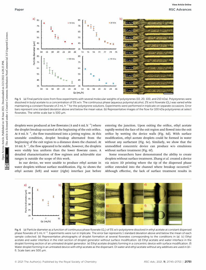
Fig. 5 (a) Final particle sizes from flow experiments with several molecular weights of polystyrenes (10, 20, 100, and 210 kDa). Polystyrenes weredissolved in butyl acetate to a concentration of 5% w/v. The continuous phase (aqueous polyvinyl alcohol, 2% w/v) flowrate (Qc) was varied whilemaintaining a constant flowrate of 2 mL h�1 for the polystyrene solutions. Experiments were performed in triplicate on separate occasions. Errorbars represent one standard deviation above and below the mean value. (b) Representative images of the flow for 100 kDa polystyrenes at selectflowrates. The white scale bar is 500 mm.
Paper RSC Advances
Ope
n A
cces
s A
rtic
le. P
ublis
hed
on 1
8 Ju
ne 2
021.
Dow
nloa
ded
on 3
/21/
2022
4:2
8:25
PM
. T
his
artic
le is
lice
nsed
und
er a
Cre
ativ
e C
omm
ons
Attr
ibut
ion-
Non
Com
mer
cial
3.0
Unp
orte
d L
icen
ce.
View Article Online
droplets were produced at low owrates (4 and 6 mL h�1) wherethe droplet breakup occurred at the beginning of the exit orice.At 8 mL h�1, the ow transitioned into a jetting regime. At thisunstable condition, droplet breakup alternated from thebeginning of the exit region to a distance down the channel. At10 mL h�1, the ow appeared to be stable, however, the dropletswere visibly less uniform than the lower owrate cases. Adetailed characterization of ow regimes and achievable sizeranges is outside the scope of this work.
In our device, we were unable to produce ethyl acetate inwater droplets without surface modication. Fig. 6c shows theethyl acetate (le) and water (right) interface just before
Fig. 6 (a) Particle diameter as a function of continuous phase flowrate (Qphase flowrate of 1 mL h�1. Experiments were run in triplicate. The errorsample collected. (b) Representative photographs of droplet formationacetate and water interface in the inlet section of droplet generator witdroplet forming section of an untreated droplet generator. (e) Ethyl acetaWater droplet forming in an untreated device with ethyl acetate as the dispf). Scale bars are 500 mm.
© 2021 The Author(s). Published by the Royal Society of Chemistry
entering the junction. Upon exiting the orice, ethyl acetaterapidly wetted the face of the exit region and owed into the exitorice by wetting the device walls (Fig. 6d). With surfacemodication, ethyl acetate droplets could be formed in waterwithout any surfactant (Fig. 6e). Similarly, we show that theunmodied concentric device can produce w/o emulsionswithout surface treatment (Fig. 6f).
Some researchers have demonstrated the ability to createdroplets without surface treatment. Zhang et al. created a devicevia micro 3D printing where the tip of the dispersed phaseorice extended into the channel where breakup occurred.11
Although effective, the lack of surface treatment results in
c) of 5%w/v polystyrene dissolved in ethyl acetate at constant dispersedbar represents 1 standard deviation above and below the mean of eachat several flowrates corresponding to the conditions in (a). (c) Ethylhout surface modification. (d) Ethyl acetate and water interface in thete droplets forming in a concentric device with surface modification. (f)ersant. DI water and ethyl acetate without any additives are used in (d–
RSC Adv., 2021, 11, 21745–21753 | 21751

RSC Advances Paper
Ope
n A
cces
s A
rtic
le. P
ublis
hed
on 1
8 Ju
ne 2
021.
Dow
nloa
ded
on 3
/21/
2022
4:2
8:25
PM
. T
his
artic
le is
lice
nsed
und
er a
Cre
ativ
e C
omm
ons
Attr
ibut
ion-
Non
Com
mer
cial
3.0
Unp
orte
d L
icen
ce.
View Article Online
droplets wetting onto the tip of the nozzle. This may be prob-lematic with a dispersed phase containing a polymer as anydroplets that stick to the walls of the device have the potential tosolidify, leading to device fouling. Rening our design with anextended conical orice to inject polymer solution into the exitchannel may enable droplet production without graing;however, the fouling issue with handling polymer solutionsremains. The small features required by this design change arealso not favourable for desktop 3D printers.
An earlier device reported by Zhang et al. also utilized a 3Djunction to generate droplets.15 They were able to producedroplets without surface modication in an arrangementsimilar to our concentric device. They used silicone oil as thedispersed phase, noting that if the oil wet the channel wallsdroplets could no longer be formed. Other uids with evengreater tendency to wet the surface may not be suitable fordroplet generation in their device. We suspect that withoutsurface modication in their device, polymer solution dropletswould be difficult to reliably produce due to wetting and foulingissues.
Polystyrene particles
The ability to target particles of a specic size was demonstratedwith the planar device and several molecular weights of poly-styrene. The morphology of 10, 20, and 100 kDa polystyreneparticles of similar sizes were analyzed by SEM imaging.Imaging of the particles (Fig. 7a–c) shows that the particles arehighly spherical with low dispersity, but have some defects onthe surface. Surface pitting was evident across all samples, asshown in SEM images and optical images (Fig. 7d). A large pit
Fig. 7 SEM micrographs and sizes of (a) 10, (b) 20, and (c) 100 kDapolystyrene particles produced using the planar device. The average,standard deviations, and coefficient of variation are given for eachsample. The scale bar in (c) applies to (a) and (b). (d) Optical micrographof 100 kDa polystyrene particles used for analysis in MATLAB®.
21752 | RSC Adv., 2021, 11, 21745–21753
and several smaller pits were present on the surface of mostparticles. This is a consequence of the phase separation thatoccurs during drying. As solvent diffuses from the polystyrene–solvent droplets, water also diffuses into the droplets. Thiscauses solvent and water to phase separate from the polystyrenerich phase. The solvent–water phase is encapsulated in thedroplets and eventually settles to the outer surface where itremains as the polystyrene phase loses enough solvent tosolidify. Ono et al. discussed this process in detail as a functionof both solvent concentration and polymer molecular weight.43
If the defects are undesired, higher molecular weights andhigher concentrations of polystyrene were shown to help reducethe pitting effect.
Conclusions
We present a simple method of surface modication and twodroplet generator designs that were manufactured usinga commercial desktop SLA printer and resin system. Thesurfaces of the polymeric devices were modied by graingmethacrylic acid onto the surface by UV photograing. Thepresence of a thin layer of graed methacrylic acid wasconrmed by SEM imaging, infrared spectroscopy, and contactangle experiments. This modication enables the conversion ofnatively hydrophobic polymer surfaces to become hydrophilicand enable the production of oil in water dispersions. Thiscoating method is an addition to only a few other demonstratedmethods of surface modication for 3D printed droplet gener-ators, where the surfaces tend to be natively hydrophobic. Wedemonstrated the applicability of the coating in our dropletgenerator designs by producing a range of <100 mm polystyreneparticles, and the ability to target a specic particle size withnarrow size distributions across compositions.
Conflicts of interest
There are no conicts of interest to declare.
Acknowledgements
We would like to acknowledge nancial support of the U.S.Army Research Laboratory through Cooperative AgreementW911NF-19-2-0152. The views and conclusions contained inthis document are those of the authors and should not beinterpreted as representing the official policies, either expressedor implied, of the U.S. Army Research Laboratory or the U.S.government. The U.S. Government is authorized to reproduceand distribute reprints for Government purposes notwith-standing any copyright notation herein. The authors are grate-ful to Shankar Kharal and Anjana Khanal of the Haase ResearchGroup for discussions on contact angle measurements andusage of their instrument.
References
1 N. Bhattacharjee, A. Urrios, S. Kang and A. Folch, Lab Chip,2016, 16, 1720–1742.
© 2021 The Author(s). Published by the Royal Society of Chemistry

Paper RSC Advances
Ope
n A
cces
s A
rtic
le. P
ublis
hed
on 1
8 Ju
ne 2
021.
Dow
nloa
ded
on 3
/21/
2022
4:2
8:25
PM
. T
his
artic
le is
lice
nsed
und
er a
Cre
ativ
e C
omm
ons
Attr
ibut
ion-
Non
Com
mer
cial
3.0
Unp
orte
d L
icen
ce.
View Article Online
2 D. J. Guckenberger, T. E. de Groot, A. M.Wan, D. J. Beebe andE. W. Young, Lab Chip, 2015, 15, 2364–2378.
3 V. Mehta and S. N. Rath, Bio-Des. Manuf., 2021, 4, 311–343.4 A. V. Nielsen, M. J. Beauchamp, G. P. Nordin andA. T. Woolley, Annu. Rev. Anal. Chem., 2020, 13, 45–65.
5 L. Wang and M. Pumera, Trends Anal. Chem., 2021, 135,116151.
6 M. Hashimoto, R. Langer and D. S. Kohane, Lab Chip, 2013,13, 252–259.
7 T. Femmer, A. Jans, R. Eswein, N. Anwar, M. Moeller,M. Wessling and A. J. C. Kuehne, ACS Appl. Mater.Interfaces, 2015, 7, 12635–12638.
8 Y. H. Hwang, T. Um, J. Hong, G. N. Ahn, J. Qiao, I. S. Kang,L. Qi, H. Lee and D. P. Kim, Adv. Mater. Technol., 2019, 4,1900457.
9 S. Waheed, J. M. Cabot, N. P. Macdonald, T. Lewis,R. M. Guijt, B. Paull and M. C. Breadmore, Lab Chip, 2016,16, 1993–2013.
10 L. Shang, Y. Cheng and Y. Zhao, Chem. Rev., 2017, 117, 7964–8040.
11 J. Zhang, W. Xu, F. Xu, W. Lu, L. Hu, J. Zhou, C. Zhang andZ. Jiang, J. Food Eng., 2021, 290, 110212.
12 A. J. L. Morgan, L. Hidalgo San Jose, W. D. Jamieson,J. M. Wymant, B. Song, P. Stephens, D. A. Barrow andO. K. Castell, PLoS One, 2016, 11, e0152023.
13 Q. Ji, J. M. Zhang, Y. Liu, X. Li, P. Lv, D. Jin and H. Duan, Sci.Rep., 2018, 8, 4791.
14 T. Kanai and M. Tsuchiya, Chem. Eng. J., 2016, 290, 400–404.15 J. M. Zhang, E. Q. Li, A. A. Aguirre-Pablo and
S. T. Thoroddsen, RSC Adv., 2016, 6, 2793–2799.16 Y. Morimoto, M. Kiyosawa and S. Takeuchi, Sens. Actuators,
B, 2018, 274, 491–500.17 Y. Morimoto, W. H. Tan and S. Takeuchi, Biomed.
Microdevices, 2009, 11, 369–377.18 R. Chen, X. Chen, X. Jin and X. Zhu, Polym. Chem., 2017, 8,
2953–2958.19 M. Mohamed, H. Kumar, Z. Wang, N. Martin, B. Mills and
K. Kim, J. Manuf. Mater. Process., 2019, 3, 26.20 S. Vijayan and M. Hashimoto, RSC Adv., 2019, 9, 2822–2828.21 J. M. Zhang, A. A. Aguirre-Pablo, E. Q. Li, U. Buttner and
S. T. Thoroddsen, RSC Adv., 2016, 6, 81120–81129.22 Z. Zhou, T. Kong, H. Mkaouar, K. N. Salama and J. M. Zhang,
Sens. Actuators, A, 2018, 280, 422–428.
© 2021 The Author(s). Published by the Royal Society of Chemistry
23 H. V. Nguyen, H. Q. Nguyen, V. D. Nguyen and T. S. Seo, Sens.Actuators, B, 2019, 296, 126676.
24 P. J. E. M. van der Linden, A. M. Popov and D. Pontoni, LabChip, 2020, 20(22), 4128–4140.
25 H. Gong, B. P. Bickham, A. T. Woolley and G. P. Nordin, LabChip, 2017, 17, 2899–2909.
26 J. M. Zhang, Q. Ji, Y. Liu, J. Huang and H. Duan, Lab Chip,2018, 18, 3393–3404.
27 A. I. Shallan, P. Smejkal, M. Corban, R. M. Guijt andM. C. Breadmore, Anal. Chem., 2014, 86, 3124–3130.
28 K. Ohtani, M. Tsuchiya, H. Sugiyama, T. Katakura,M. Hayakawa and T. Kanai, J. Oleo Sci., 2014, 63, 93–96.
29 L. Brandhoff, S. v. d. Driesche, F. Lucklum andM. J. Vellekoop, Bio-MEMS and Medical Microdevices II,Proc. SPIE, Barcelona, Spain, 2015, vol. 9518.
30 X. Wang, X. Cai, Q. Guo, T. Zhang, B. Kobe and J. Yang,ChemComm, 2013, 49, 10064–10066.
31 C. F. Carlborg, T. Haraldsson, K. Oberg, M. Malkoch andW. van der Wijngaart, Lab Chip, 2011, 11, 3136–3147.
32 C. E. Hoyle and C. N. Bowman, Angew. Chem., Int. Ed. Engl.,2010, 49, 1540–1573.
33 G. Pardon, F. Saharil, J. M. Karlsson, O. Supekar,C. F. Carlborg, W. van der Wijngaart and T. Haraldsson,Microuid. Nanouid., 2014, 17, 773–779.
34 L. H. Sperling, Introduction to Physical Polymer Science, Wiley,Hoboken, New Jersey, 2006.
35 A. R. Abate, A. T. Krummel, D. Lee, M. Marquez, C. Holtzeand D. A. Weitz, Lab Chip, 2008, 8, 2157–2160.
36 G. Gonzalez, A. Chiappone, K. Dietliker, C. F. Pirri andI. Roppolo, Adv. Mater. Technol., 2020, 5, 2000374.
37 O. N. Tretinnikov, V. V. Pilipenko and L. K. Prikhodchenko,Polym. Sci., Ser. B, 2012, 54, 427–433.
38 G. Li, G. He, Y. Zheng, X. Wang and H. Wang, J. Appl. Polym.Sci., 2012, 123, 1951–1959.
39 S. Hu, X. Ren, M. Bachman, C. E. Sims, G. P. Li andN. Allbritton, Anal. Chem., 2002, 74, 4117–4123.
40 T. Richey, H. Iwata, H. Oowaki, E. Uchida, S. Matsuda andY. Ikada, Biomaterials, 2000, 21, 1057–1065.
41 J. Jang and W.-S. Go, Fibers Polym., 2008, 9, 375–379.42 M. Z. Shahid, M. R. Usman, M. S. Akram, S. Y. Khawaja and
W. Afzal, J. Chem. Eng. Data, 2017, 62, 1198–1203.43 T. Ono, M. Yamada, Y. Suzuki, T. Taniguchi andM. Seki, RSC
Adv., 2014, 4, 13557–13564.
RSC Adv., 2021, 11, 21745–21753 | 21753