
HYDROLOGY AND WATER QUALITY REVIEW FINAL DRAFT€¦ · Coyote Highlands Hydrology and Water Quality...
30
HYDROLOGY AND WATER QUALITY REVIEW FINAL DRAFT For COYOTE HIGHLANDS DEVELOPMENT Santa Clara County, CA May 8, 2012 Prepared For: Panorama Environmental, Inc. One Embarcadero Center #740 San Francisco, CA 94111 Tel: (650) 373‐1200 Prepared By: 870 Market Street, Suite 1278 San Francisco, CA 94102 Tel: (415) 433‐4848 Fax: (415) 433‐1029
Transcript of HYDROLOGY AND WATER QUALITY REVIEW FINAL DRAFT€¦ · Coyote Highlands Hydrology and Water Quality...

HYDROLOGY AND WATER QUALITY REVIEW FINAL DRAFT
For COYOTE HIGHLANDS DEVELOPMENT
Santa Clara County, CA May 8, 2012
Prepared For: Panorama Environmental, Inc. One Embarcadero Center #740
San Francisco, CA 94111 Tel: (650) 373‐1200
Prepared By:
870 Market Street, Suite 1278 San Francisco, CA 94102
Tel: (415) 433‐4848 Fax: (415) 433‐1029

Coyote Highlands Hydrology and Water Quality - DRAFT May 8, 2012
i
TABLE OF CONTENTS APPROACH TO ANALYSIS.......................................................................................1 THRESHOLDS OF SIGNIFICANCE .......................................................................1
PROJECT DESCRIPTION Project Site .....................................................................................................................2 Regulatory Setting .........................................................................................................2 Hydrology and Water Quality Issues Not Discussed Further........................................5
EXISTING CONDITIONS FEMA Flooding .............................................................................................................5 Landslide Hazard ...........................................................................................................7 Dam Failure ...................................................................................................................8 Site Drainage..................................................................................................................9 Water Quality...............................................................................................................20
PROJECT IMPACTS AND MITIGATION MEASURES Impact Hydro1: Flooding and Flood Zones...................................................................5 Impact Hydro2: Landslides............................................................................................7 Impact Hydro3: Dam Failure .........................................................................................8 Impact Hydro4: Drainage Patterns Causing Flooding ...................................................9 Existing Site Drainage Pattern ..............................................................................9 Post-Project Site Drainage Patterns ....................................................................13 Mitigation............................................................................................................18 Impact Hydro5: Drainage Patterns Causing Erosion ...................................................13 Impact Hydro6: Groundwater Depletion .....................................................................19 Impact Hydro7: Water Quality ....................................................................................20 Existing Surface Water Quality ..........................................................................20 Existing Groundwater Quality ............................................................................21 Impacts to Water Quality ....................................................................................22 Mitigation............................................................................................................24 Impact Hydro8: Violate Waste Discharge Requirements ............................................26 REFERENCES ..............................................................................................................27

Coyote Highlands Hydrology and Water Quality - DRAFT May 8, 2012
ii
LIST OF FIGURES 1: Vicinity Map..............................................................................................................4 2: FEMA Flooding Map.................................................................................................6 3: Landslide Hazard Map ..............................................................................................7 4: Dam Inundation Map.................................................................................................8 5: Existing Drainage Basin Map..................................................................................11 6: Proposed Site Drainage............................................................................................15
LIST OF TABLES 1: Existing Peak Flow Rates ........................................................................................12 2: Proposed Peak Flow Rates ......................................................................................16 3: Required Storage – Final Project Build Out ............................................................17 4: Required Storage – Phase I Only.............................................................................17

Coyote Highlands Hydrology and Water Quality – Final Draft May 8, 2012
1
APPROACH TO ANALYSIS
This impact evaluation identifies potentially significant hydrologic impacts of the project both during project construction and at completion, and describes mitigation measures needed to reduce those impacts to the level of “less than significant”.
THRESHOLDS OF SIGNIFICANCE
Appendix G of the CEQA Guidelines and the Regulatory Setting requirements considers the proposed project to have a significant environmental impact with regard to hydrology and water quality if it would:
• Violate any water quality standards or waste discharge requirements;
• Substantially deplete ground water supplies or interfere substantially with ground water recharge such that there would be a net deficit in aquifer volume or a lowering of the local ground water table level (e.g., the production rate of preexisting nearby wells would drop to a level which would not support existing land uses or planned uses for which permits have been granted);
• Substantially alter the existing drainage pattern of the site or area, including through the alteration of the course of a stream or river, in a manner which would result in substantial erosion or siltation on- or off-site;
• Substantially alter the existing drainage pattern of the site or area, including through the alteration of the course of a stream or river, or substantially increase the rate or amount of surface runoff in a manner which would result in flooding on- or off-site;
• Create or contribute runoff water which would exceed the capacity of existing or planned storm water drainage systems or provide substantial additional sources of polluted runoff;
• Otherwise substantially degrade water quality;
• Place housing within a 100-year flood hazard area as mapped on a federal Flood Hazard Boundary or Flood Insurance Rate Map or other flood hazard delineation map;
• Place within a 100-year flood hazard area structures that would impede or redirect flood flows;
• Expose people or structures to a significant risk of loss, injury or death involving flooding, including flooding as a result of the failure of a levee or dam; or
• Expose people or structures to inundation by seiche, tsunami, or mudflow.
Coyote Highlands Hydrology and Water Quality – Final Draft May 8, 2012
2
PROJECT DESCRIPTION
Project Site
Coyote Highlands, LLC and Fountain Oak Ranch, LLC proposes the construction of a 25 single family home rural residential development with associated access roads and utilities on 567 acres in unincorporated Santa Clara County, California (APN 817-23-006, 817-23-009, 817-23-012, 817-24-002, 825-29-005). The project site is currently open space livestock grazing land and is bounded by Jackson Oaks and Holiday Lakes Estates residential developments to the north, Carey Avenue to the southwest and a rural residential development along Paseo Vista to the east. The proposed project includes a 2.2 mile extension of Maple Avenue to Oak Canyon Drive. The project proposes to develop only 13% of the land while maintaining the other 87% as permanent open space. Refer to Figure 1 for project location. The purpose of this report is to evaluate the existing and proposed hydrologic conditions and assess potential storm water quality impacts due to the proposed project. This analysis is based on topographic survey data, proposed tentative map dated January 2011, preliminary Site Development plans dated December 2010 created by MH Engineering Co., and supporting reports referenced herein.
Regulatory Setting
The project site is located within two jurisdictional zones regarding storm water quality and system design1. All of the storm water runoff drains to facilities owned and maintained by the Santa Clara Valley Water District (SCVWD); however most of the site eventually drains to Monterey Bay while a small northeastern portion of the site eventually drains to San Francisco Bay. The Monterey Bay watershed is regulated by the Central Coast Regional Water Quality Control Board (RWQCB), the County of Santa Clara, and SCVWD. The southwestern drainage basin encompassing 99 percent of the site should adhere to the regulations of the County, SCVWD, and CCRWQCB for both construction and post-construction storm water quality control. The CCRWQCB is currently creating a 2011 revised draft NPDES Phase II permit. Until the draft permit is adopted, the site is required to adhere to the effective 2003 Phase II permit. Additional regulations are imposed by the south Santa Clara County Revised Regional Storm Water Management Plan of 20102.
The northeastern 4.6 acre area, which drains to San Francisco Bay, is regulated by the San Francisco Bay RWQCB, the County of Santa Clara and SCVWD. The SFRWQCB requirements are administered by the Santa Clara Valley Urban Runoff Pollution Prevention Program (SCUVRPPP). For the portion of the site subject to SCUVRPPP
1 Waterboards Map, California State Water Resources Control Board, December 7, 2010. 2 Revised Regional Storm Water Management Plan, City of Gilroy, City of Morgan Hill and County of
Santa Clara, 2010.

Coyote Highlands Hydrology and Water Quality – Final Draft May 8, 2012
3
standards, the project design should follow the regulations set forth in the C.3 Stormwater Handbook.3 Construction site controls should be designed per the Bay Area Stormwater Management Agencies Association (BASMAA) Blueprint for a Clean Bay and California Stormwater Quality Association Best Management Practices (CASQA BMP) Handbook. It should be noted that SCVWD is a member of SCVURPPP and may require the entire site to be designed to the SCVURPPP standards.
3 C.3 Stormwater Handbook. Santa Clara Valley Urban Runoff Pollution Prevention Program
(SCVURPPP). May 2006.

Coyote Highlands Hydrology and Water Quality – Final Draft May 8, 2012
4
Figure 1: Vicinity Map

Coyote Highlands Hydrology and Water Quality – Final Draft May 8, 2012
5
Hydrology and Water Quality Issues Not Discussed Further The following environmental impacts have been determined to be less than significant and are not analyzed further for the reasons given:
• Risk of Seiche: The resonant oscillation of water in an enclosed body of water is a seiche. There are no lakes or other enclosed bodies of water adjacent to the project to produce seiche events that could affect the project site.
• Risk of Tsunami: The project is not near the ocean; thus tsunami events would not affect the project site.
PROJECT IMPACTS AND MITIGATION MEASURES
Impact Hydro1: Place housing or structures within a 100-year flood hazard area or impede flood flows.
Finding: Less than Significant
Per the Federal Emergency Management Agency (FEMA) flood insurance rate map (FIRM) numbers 06085C0464H and 06085C0627H, dated May 18, 2009, the project site is located in special flood hazard area (SFHA) Zone D, designating an area in which flood hazards are undetermined, but possible. The FEMA FIRM identifies the site as being located in unincorporated lands of Santa Clara County. Developed lands located adjacent to the project site incorporated into the City have been designated Zone X. The Zone X designation is for areas of 0.2% (i.e. 500-year) chance flood; areas of 1% (i.e. 100-year) chance flood with average depths of less than one foot or with drainage areas less than one square mile. According to the FEMA map, the Zone D boundary coincides with the Corporate Limits for the City of Morgan Hill. The site may be determined to be Zone X by a future in-depth study. Both Zones D and X are considered outside of the designated 100-year special flood hazard area. As such, the project does not place structures within the flood hazard area, and thus has a less than significant impact on the regulatory floodplain.
The FEMA SFHA designations are shown on Figure 2.

Coyote Highlands Hydrology and Water Quality – Final Draft May 8, 2012
6
Figure 2: FEMA Special Flood Hazard Zones

Coyote Highlands Hydrology and Water Quality – Final Draft May 8, 2012
7
Impact HYDRO2: Expose people to landslide or mudflow hazards.
Finding: Less than Significant with Mitigation
According to the Landslide Inventory Map of the Mt Sizer Quadrangle,4 (Figure 3) the project site is located within the limits of existing or known landslides. Landslides exist around Anderson Lake and Coyote Creek to the northeast and extend into the project site, specifically adjacent to the onsite creeks. Existing onsite steep slopes of up to 45% may pose a landslide or mudflow hazard. A geologist should be retained during the detailed design and construction of the project to ensure the slope stability of the onsite lands, and for general soil construction suitability. By incorporating any mitigation recommendations made by the geologist during detailed design, this potential impact would be reduced to less than significant with mitigation.
Figure 3: Landslide Hazard Map
4 Landslide Inventory Map, Mt Sizer Quadrangle. State of California Department of Conservation. 2006.

Coyote Highlands Hydrology and Water Quality – Final Draft May 8, 2012
8
Impact Hydro3: Expose people or structures to a significant risk of loss, injury or death involving flooding...as a result of the failure of ... a dam.
Finding: Less than Significant
The site is not within the inundation boundaries of Anderson, Chesbro, Uvas or Coyote Dams5. The Santa Clara Valley Water District (SCVWD) performed an analysis of the effects of Anderson Dam failure in 20036. This analysis resulted in an expected maximum inundation depth of 13.5 feet (elevation 425.6 feet) at the low lying access roads to the project site within 2 hours and 36 minutes after dam failure. There is no expected inundation at the project site. Although roadways providing access to the site may experience significant inundation, there is no expected risk due to loss, injury or depth due to flooding. Therefore, the potential impact is less than significant.
Figure 4: Anderson Dam Inundation Limits
5 Dam Failure Inundation Hazard Map for Morgan Hill. Association of Bay Area Governments’
(ABAG). 1995. Website: http://www.abag.ca.gov. 6 Anderson Dam EAP Map 2003 Flood Inundation Map, Sheet 7, Santa Clara Valley Water District,
2003.

Coyote Highlands Hydrology and Water Quality – Final Draft May 8, 2012
9
Impact HYDRO4: Substantially alter the existing drainage pattern of the site in a manner which would exceed the capacity of storm water drainage systems, or result in substantial flooding on- or off-site.
Finding: Less than Significant with Mitigation
Existing Site Drainage Pattern
The existing site overlays five distinct drainage basins. Lands to the northwest are tributary to Fisher Creek, the middle of the site flows to Foothill Creek7 and the southern portion of the site flows to Corralitos or South Corralitos Creek. A small portion in the northeast of the site flows to an offsite tributary of Coyote Creek. All of the onsite creeks flow westerly to Tennant and Corralitos Creeks before discharging to the south and eventually contributing to East Little Llagas Creek. Within the project limits all three of the creeks have natural channels. For the purpose of this analysis, it is assumed that water tributary to the project site from offsite properties is included in the overall site discharge. Portions of the upper lots (numbers 9, 10, and Open Space 2) totaling approximately 4.6 acres are tributary to Coyote Creek, located northwest of the site.
As described above, the five existing project site drainage basins include: Coyote Creek to the east, Fisher Creek to the north, Foothill Creek in the center of the site, Corralitos Creek and South Corralitos Creek to the southwest. Figure 5 shows the delineation of these basins. The basins include the project area and the properties to the northeast and southwest which drain through the site and contribute to the onsite creeks. With the exception of the Coyote basin, the site is generally sloped towards the east and south. The entire project site is relatively steep, with an average slope of approximately 10%. The upper boundary of each basin lies approximately on the ridge line. For this analysis, the lower boundaries of the basins are defined as the points in which the creeks or tributary areas reach the edge of the site.
The existing northern drainage basin for Fisher Creek is approximately 154 acres and ranges from elevation 1,220 feet in the east to elevation 460 feet in the west where the creek exits the site. The basin includes both onsite lands and offsite property which flows through the site. The Fisher Creek basin slopes from the northeast to the southwest, under Carey Avenue and Foothill Ave, into an engineered channel before its confluence with Tennant Creek near Hill Road. There are no known engineered drainage facilities onsite for Fisher Creek.
7 The naming convention used for Fisher Creek and Foothill Creek is based on the Army Corp of Engineer’s designations and those used within the project Tentative Map. Note that these names differ from those shown on FEMA Maps. In addition, the onsite Fisher Creek is in no way related to, or tributary to, the Fisher Creek located within the San Francisco Bay Watershed. On-site Fisher Creek is tributary to Corralitos Creek and the Monterey Bay Watershed.

Coyote Highlands Hydrology and Water Quality – Final Draft May 8, 2012
10
The existing middle drainage area includes Foothill Creek. Foothill Creek basin is approximately 277 acres and ranges from elevation 1,230 feet on the offsite property to the northeast to onsite elevation 420 feet at Carey Lane. The basin includes only a small portion of offsite lands to the west of the site. Near the top of the basin, at elevation 1,054, there is a small detention pond, capable of holding approximately 18,000 cubic feet of runoff. Foothill Creek flows from west to east beneath Ranch Road, Carey Lane and Foothill Avenue before its convergence with Tennant Creek near the intersection of Hill Road and Maple Ave. The existing drainage systems constructed on the onsite reach of Foothill Creek are a 36” culvert beneath Ranch Road and a 42” culvert beneath Carey Lane.
The Corralitos Creek drainage basin includes the southern portion of the property and offsite lands to the south and east which total approximately 194 acres. The basin ranges from elevation 1490 feet in the east to elevation 410 feet in the west at Maple Ave and Paseo Robles. Rainfall on this portion of the site flows to the south and west, beneath Paseo Robles before its confluence with Tennant Creek. The creek channel remains natural until just upstream of the East Little Llagas junction. The only known existing drainage facilities onsite are an 18” culvert beneath an existing dirt access path and a 42” culvert beneath Paseo Robles Avenue.
South Corralitos Creek accepts runoff from the southwest corner of the site, as well as offsite area. The basin used in this study is approximately 19 acres and ranges from 1,320 feet to 1,080 feet. No part of the defined creek channel is located onsite. The sub-basin runoff flows south to South Corralitos Creek and beneath Paseo Robles before merging with Corralitos Creek.
The small basin along the ridge line to the northwest of the project site sheet flows to a tributary of Coyote Creek. Approximately 4.6 acres drains to the west, from elevation 1,240 to elevation 1,210. Coyote Creek then flows north and west, eventually discharging to the San Francisco Bay.


Coyote Highlands Hydrology and Water Quality – Final Draft May 8, 2012
12
To estimate peak storm water runoff from the site before and after development, the Hydrograph Method (HM) was employed per the Santa Clara County Drainage Manual (SCCDM)8. The Hydrograph Method analyzes land use, site imperviousness, soil type, project size, and rainfall rates for a particular project location to estimate a peak flow from each drainage basin for a particular storm recurrence and duration. The Army Corps of Engineers Hydrologic Engineering Center Flood Hydrograph Package version 4.1 (HEC-1) was used to perform HM calculations. Land use for the site will change with the proposed development from open space grazing land to low density rural residential within the footprints of roadway and housing development.
Existing soils underlying the site are Natural Resources Conservation Service Hydrologic Soil Groups C and D9, encompassing 250 acres and 317 acres respectively. Soil Group C encompasses soils with moderate to high runoff potential and slow infiltration rates; this includes onsite clay loam. The onsite clay and stone clay loam is included in Soil Group D, qualified as having high runoff potential and very slow infiltration rates. The areas with group D soil experience greater peak runoff values and faster times of concentration (i.e. quicker peak runoff) than those areas characterized by group C soils.
The Hydrograph Method uses soil type in combination with land use to determine the SCS Curve Number. The Curve Number (CN) ranges from 0 to 100, with 100 being the most pervious and 0 being impervious. In addition to soil type and land use, curve numbers are modified using Antecedent Moisture Content (AMC). An AMC of II ½ was used for the 100 year design storm per the County Drainage Manual to represent saturated soil at the start of the storm. An AMC of II ¼ was used for the 2 year and 10 year storms to represent less saturated soils.
Rainfall intensity rates for the project site are based on a mean annual precipitation (MAP) value of 20”. Corresponding intensity-duration-frequency (IDF) curves are used to determine the rainfall intensity at each storm frequency and duration. The project site is analyzed for the 2-year, 10-year and 100-year design storms. The Hydrograph Method calculates runoff based on 24 hour storm duration. The pre-project peak flows are listed below in Table 1 for each basin.
Table 1: Existing Peak Flow Rates, Q (cfs) from HEC-1 Basin 2 year Storm 10 year Storm 100 year Storm
Fisher 26.7 75.6 170.0 Foothill 32.1 106.4 259.8 Coyote 0.6 2.5 6.8 Corralitos 28.4 79.3 176.9 South Corralitos 5.2 14.9 33.6
8 Drainage Manual. Santa Clara County, California, prepared by Schaaf & Wheeler. August 14, 2007. 9 Soil Map – Eastern Santa Clara Area (CA646), California. Web Soil Survey - National Cooperative
Soil Survey, Natural Resources Conservation Service. July 27, 2010. Website: http://websoilsurvey.nrcs.usda.gov.

Coyote Highlands Hydrology and Water Quality – Final Draft May 8, 2012
13
Post-Project Site Drainage Pattern
The proposed project will generally maintain the existing basin drainage patterns. Most of the site will remain undisturbed open space, draining via Fisher, Foothill, and Corralitos Creeks to Monterey Bay. Development occurring onsite will not alter the natural drainage boundaries. See Figure 6 for a post-project drainage map. The small basin tributary to Coyote Creek will maintain its existing drainage patterns according to the proposed grading plan by MH Engineers. This analysis was performed assuming full build-out (Phases I and II) of the Site. Phase I includes the construction of Maple Avenue extension and shared access drives while Phase II involves the construction of individual driveways and houses. A comparison between Phase I and cumulative Phase I/Phase II impacts is included at the end of this section.
The Fisher basin impervious area will increase by 1.2% due to the construction of 1,200 feet of Maple Avenue, access road A, and residential lots 2, 7, 8 and 9. The construction of lots 1-6 and 10-21, access roads B, C and D, and a 4,300 foot length of Maple Avenue will increase the imperviousness of the Foothill basin by 3.2%. Coyote Basin will increase in impervious area by 5.9% due to the construction of houses and associated structures on lots 9 and 10. Corralitos Creek basin impervious area will increase by 2.4% due to the 6,800 foot construction of Maple Avenue, lots 17, 21-23, C1, and offsite dual water storage tanks and access roads. A 3.6% increase in impervious area will occur within the South Corralitos Creek basin due to the construction in lots C1 and C2.
The project proposes to use drainage ditches on the upstream side of the proposed Maple Road extension in order to capture sheet flow. Storm drain inlets located along the roadway extension will capture flow from drainage ditches as well as roadway drainage and collect it into an underground drainage system. The drainage system pipes convey the collected runoff downhill before discharging through flared outlets into the existing onsite creeks and tributary swales. Creeks which originate upstream of the roadway will enter proposed culverts beneath Maple Avenue and the onsite driveways to maintain existing drainage patterns. Details were not provided at the time of this study regarding pipe sizes and inverts; therefore it was not possible to verify capacity. Pipe sizing and design should meet requirements of the County of Santa Clara in order to safely convey storm waters.
Parcel specific drainage networks have not been proposed at the time of Tentative Map submittal. Due to the steep slopes and undefined drainage pathways, localized drainage systems are unnecessary for most of the developed areas of the parcels. Drainage infrastructure may be deemed necessary with the construction of the houses in order to divert upstream flows around the structures, especially where concentrated by a down sloping driveway. In order to mitigate potential negative effects of localized drainage changes, infrastructure design should follow the Santa Clara County drainage requirements and discharge sufficiently downstream with appropriate outlet measures as
Coyote Highlands Hydrology and Water Quality – Final Draft May 8, 2012
14
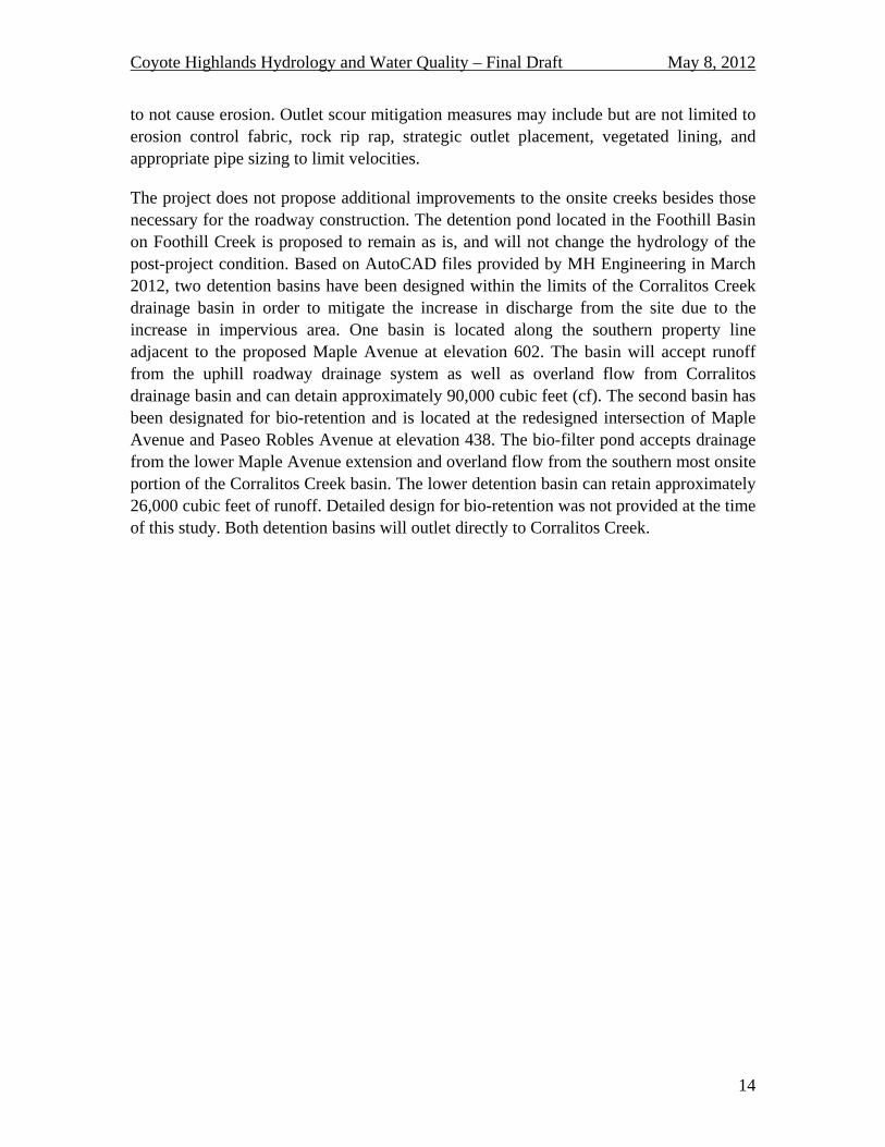
to not cause erosion. Outlet scour mitigation measures may include but are not limited to erosion control fabric, rock rip rap, strategic outlet placement, vegetated lining, and appropriate pipe sizing to limit velocities.
The project does not propose additional improvements to the onsite creeks besides those necessary for the roadway construction. The detention pond located in the Foothill Basin on Foothill Creek is proposed to remain as is, and will not change the hydrology of the post-project condition. Based on AutoCAD files provided by MH Engineering in March 2012, two detention basins have been designed within the limits of the Corralitos Creek drainage basin in order to mitigate the increase in discharge from the site due to the increase in impervious area. One basin is located along the southern property line adjacent to the proposed Maple Avenue at elevation 602. The basin will accept runoff from the uphill roadway drainage system as well as overland flow from Corralitos drainage basin and can detain approximately 90,000 cubic feet (cf). The second basin has been designated for bio-retention and is located at the redesigned intersection of Maple Avenue and Paseo Robles Avenue at elevation 438. The bio-filter pond accepts drainage from the lower Maple Avenue extension and overland flow from the southern most onsite portion of the Corralitos Creek basin. The lower detention basin can retain approximately 26,000 cubic feet of runoff. Detailed design for bio-retention was not provided at the time of this study. Both detention basins will outlet directly to Corralitos Creek.


Coyote Highlands Hydrology and Water Quality – Final Draft May 8, 2012
16
The project site proposes to use drainage swales to convey surface flow to onsite creeks and detention ponds. Limited underground storm drain infrastructure is also proposed at the roadway infrastructure. Roadside drainage swales will run adjacent to Maple Avenue to accept upstream runoff, flowing through culverts beneath the roadway before discharging into the onsite creeks. Drainage swales will also be established to direct flow from residential parcels before converging with the existing onsite Creeks. Roadway and surface drainage within the Corralitos Creek basin will flow overland or be piped into one of two detention ponds. The detention ponds will outlet directly to Corralitos Creek.
Due to the increase in impervious area, the peak runoff from the site would increase in the absence of mitigation. Refer to Table 2 for the results of Schaaf & Wheeler's analysis for post-project peak runoff rates for final build-out of Phases I and II. The total runoff from the site and contributing offsite areas for the 100-year, 24 hour storm would increase from 647.1 cfs to 664.8 cfs.
Table 2: Proposed Project Peak Flow Rates (cfs) – Final Project Build Out Basin 2 year Storm 10 year Storm 100 year Storm
Fisher 28.1 78.1 174.1 Foothill 36.7 113.0 268.3 Coyote 0.8 2.8 7.1 Corralitos 30.4 82.2 180.6 South Corralitos 5.9 15.8 34.8
The project site is located in unincorporated Santa Clara County, outside of the jurisdictional boundaries of the South Santa Clara County Storm Water Management Plan (SWMP)10 and Morgan Hill’s Storm Drain Design Standards11 requirements. According to the permit boundaries designated by the South County SWMP, the project is not required to reduce post project flows to pre project conditions. However, Schaaf & Wheeler has concluded that the jurisdictional boundaries detailed in the South County SWMP should be extended to include the Coyote Highlands Site since the project discharges to waters controlled by the City of Morgan Hill and waters within the jurisdictional boundaries of the South County SWMP. Therefore, the Site will be required to meet the standards required by the South County SWMP and must provide storage in order to limit the post project discharges to pre project conditions.
The project proposes to install detention basins at the discharge points for the Corralitos Creek drainage basin to reduce the post-project peak discharge to pre-project conditions, promote infiltration and water cleansing. Since detention basin outlet works were not designed at the time of this study, the storage volumes were determined based on basin
10 Revised Storm Water Management Plan. City of Gilroy, City of Morgan Hill and County of Santa
Clara. February 22, 2010. 11 Storm Drain Design Standards. City of Morgan Hill, Engineering Department. Website:
http://www.morgan-hill.ca.gov/.

Coyote Highlands Hydrology and Water Quality – Final Draft May 8, 2012
17
hydrographs for each design storm. The area between the pre-project and post-project hydrographs represents the volume of storage required. The required storage volumes to achieve the proposed peak discharge mitigation for the final build out of Phases I and II are calculated for each design storm and return interval. The results are tabulated in Table 3 below.
Table 3: Required Storage Volumes (cf) – Final Project Build Out Drainage Basin Storm
Duration Fisher Foothill Coyote Corralitos S. Corralitos 2 yr 9,930 50,210 1,620 24,670 3,450 10 yr 12,000 61,550 2,020 29,660 4,130 100 yr 11,520 59,860 2,000 28,130 3,880
The required storage listed in Table 3 is specific to mitigating the peak discharge and does not address other requirements that may be placed upon the project by regulatory agencies. The project plans current at the time of this study proposed a total of 116,000 cubic feet of storage for the Corralitos Creek basin. The proposed storage volume exceeds the requirements for restricting the peak discharge to pre project conditions for the 100 year design storm for the Corralitos basin alone. No storage has been provided for any of the other 4 basins. In the absence of detailed detention basin design, the Fisher detention basin should provide a minimum of 12,000 cf of storage and the South Corralitos detention basin should provide 4,130 cf. At least 61,550 cf of storage should be provided in the Foothill Basin, and the Coyote detention basin should provide 2,020 cf of storage.
The following table reflects the storage requirements for each basin if only Phase I is constructed. Phase I includes the construction of the Maple Avenue extension, driveways to lots C1 and C2 and 2, offsite water tank access road, and the shared access roads per the Tentative Map.
Table 4: Required Storage Volumes (cf) – Phase I Only Drainage Basin Storm
Duration Fisher Foothill Coyote Corralitos S. Corralitos 2 yr 4,747 20,050 484 21,874 2,215 10 yr 5,819 24,747 604 26,324 2,654 100 yr 5,742 24,403 597 25,011 2,502
In order to mitigate the peak discharge for Phase I construction only, the Fisher detention basin should provide a minimum of 5,820 cf of storage and the South Corralitos detention basin should provide 2,700 cf. At least 24,800 cf of storage should be provided in the Foothill Basin, and the Coyote detention basin should provide 605 cf of storage.

Coyote Highlands Hydrology and Water Quality – Final Draft May 8, 2012
18
Mitigation
As shown in Tables 1 and 2, the project results in increased runoff from the site due to the increased impervious surfaces. Based on our analysis, the project has included insufficient storage to mitigate this impact. Only within the Corralitos Creek basin has storage to mitigate peak runoff increases been provided. The project shall include detention basins within each creek catchment in order to mitigate the peak discharge to pre-project conditions. The drainage basins will outlet to existing creeks that have not been analyzed for capacity and may not be able to convey an increase in peak discharge. As such, the outlet works for the detention basins shall be designed to limit post-project flows to pre-project levels such that the existing frequency of capacity exceedance of any existing downstream culverts or floodplain flooding is maintained or decreased. A Detention Basin Design Plan shall be submitted to Santa Clara County 60 days prior to project construction of Phase I. The designs shall include basin-scale detention ponds to mitigate Phase I impacts and residential lot-sized basins to mitigate the impacts of Phase II. The Detention Basin Design Plan shall include sufficient storage volume to mitigate the increase in runoff for both Phase I and Phase II of the project. During Phase I, the basin-scale detention ponds located outside of the residential lots shall be constructed. During Phase II, the County shall require each residential lot owner to construct detention basins and drainage facilities within their lot to mitigate their localized impact per the Detention Basin Design Plan.
With these mitigations, impacts to flood risk and storm drain systems as a result of the project will be reduced to a less than significant level.

Coyote Highlands Hydrology and Water Quality – Final Draft May 8, 2012
19
Impact HYDRO5: Substantially alter the existing drainage pattern of the site in a manner which would result in substantial erosion or siltation on- or off-site.
Finding: Less than Significant with Mitigation
As described above, peak runoff from the site shall be mitigated with additional detention basins designed to not exceed pre-project peak runoff for the 2-, 10-, and 100-year storm events. The portion of the site that drains to San Francisco Bay via Coyote Creek is under the jurisdiction of the San Francisco RWQCB, and is required to provide hydromodification mitigation for new or replaced impervious area greater than 1 acre. The current design provides for 0.4 acres of impervious area in the final build-out condition, and therefore hydromodification is not required. Since current plans do not detail housing construction and residential parcel improvements (i.e. impervious tennis courts, swimming pools, etc) it is important that future design limits construction of impervious area to less than one acre. If impervious area greater than one acre is designed within the onsite “Coyote” basin tributary to Coyote Creek, the project shall include hydromodification mitigation meeting or exceeding the specifications outlined in the SCVURPPP hydromodification mitigation plan (HMP).
An offsite soil stockpile has been designated for approximately 10,000 cubic yards of cut soil storage. At the time of this study, the stockpile location had not been determined. The pile should be located in an area as to not disrupt natural drainage patterns. Any temporary on-site stockpiles should utilize appropriate construction level best management practices (BMPs). At later stages of planning, a Stormwater Pollution Prevention Plan (SWPPP) and a Stormwater Management Plan (SWMP) will be prepared to avoid on-site erosion. These requirements, and other impacts and mitigation measures specific to sediment as a water quality concern, are discussed in Mitigation Measure HYDRO-7.
With these mitigation measures, impacts to erosion or siltation on or off site due to the project will be reduced to less than significant.
Impact HYDRO6: Substantially deplete groundwater supplies or interfere with groundwater recharge.
Finding: Less than Significant
The project site is located on the ridge between the Coyote and Llagas Creek watersheds, as described elsewhere in the report; however the SCVWD describes the northern limit of the Llagas groundwater basin to be Cochrane Road, meaning that the site is entirely underlain by the Llagas groundwater basin. Recharge of the Llagas groundwater basin is achieved through an equal combination of natural recharge and recharge activities of the SCVWD (23,000 afy each). The Llagas basin is estimated to have an operation storage capacity between 150,000 and 165,000 af, and basin pumping between 2001 and 2009

Coyote Highlands Hydrology and Water Quality – Final Draft May 8, 2012
20
ranges from 44,000 acre-feet to 50,000 acre-feet.12 The proposed project has no impact to the SCVWD recharge activities for the Llagas groundwater basin.
The surface area of the Llagas groundwater basin is 56,000 acres13. Although infiltration varies over the basin, this creates an average annual infiltration volume of 0.4 acre-feet per acre of surface area. The total impervious surface of the proposed development is about 567 acres. Applying the average annual infiltration volume (0.4 af/acre) and the most conservative assumption, that no rainfall onto post-project impervious surfaces is able to percolate into the groundwater basin, this results in a decrease of about 16 acre-feet/year of infiltration, less than one tenth of a percent decrease from existing conditions, and less than 0.05% of the historic groundwater withdrawals. This does not represent a substantial interference with groundwater recharge. Furthermore, these calculations assume zero infiltration of rainfall onto impervious areas, but in fact the project proposes to utilize drainage swales and basins which will promote infiltration of runoff from impervious surfaces.
Given these calculations, and the project plan to promote runoff through the use of open swales and strategically located basins, the impact of the project to groundwater recharge is less than significant.
Note that this finding is specific to groundwater impacts due to the projects change in land use and drainage, and does not include potential groundwater impacts related to the project water demand or supply. The project currently proposes the construction of a new well located east of the site for water supply. The proposed placement of the offsite well will result in water withdrawal from the Coyote groundwater basin. A Water Supply Assessment shall be performed for the proposed water well in order to determine the effects on groundwater supply and ensure adequate supply of water.
Impact Hydro7: Violate any water quality standards or otherwise substantially degrade water quality.
Finding: Less than Significant with Mitigation
Existing Surface Water Quality
Pajaro River is listed as an impaired water body by the EPA 303(d) list for Boron. Boron is a naturally occurring constituent of surface waters and has harmful effects on crop growth. Llagas Creek is listed as an impaired 303(d) water body for pH, chloride, low dissolved oxygen, sodium and total dissolved solids. Llagas Creek and Pajaro River are also listed as impaired due to Nitrate, whose sources are listed as septic systems, landscape maintenance, pet waste, backyard livestock waster, open space plant decay,
12 Urban Water Management Plan, Santa Clara Valley Water District 2010 13 California's Groundwater Bulletin 118

Coyote Highlands Hydrology and Water Quality – Final Draft May 8, 2012
21
animal waster and atmospheric deposition. The South County has set TDMLs for sediment, fecal coli form and nitrate in their Storm Water Management Plan (SWMP). Although the Site is not located within the jurisdictional boundaries identified by the SWMP, its waters contribute to the impaired water bodies being protected.
Existing Ground Water Quality
Groundwater quality in Santa Clara County is generally quite good. That said, contamination sites and elevated nitrate concentrations have been observed. The SCVWD monitors groundwater quality for a variety of parameters, including calcium, sodium, iron, nitrate, chloride, organic solvents or gasoline additives. The type of monitoring at any given well depends on the well location, historic and existing land uses, and the availability of groundwater data in the area. In addition, water retailers and property owners also conduct groundwater monitoring. At polluted sites, responsible parties monitor the effectiveness of cleanup efforts.
The Site is entirely underlain by the Llagas groundwater basin and abuts the Coyote groundwater basin to the northeast. Although the on-site stormwater contributes to the recharge of the Llagas groundwater basin, the project proposes to construct offsite water supply wells located within the Coyote basin. Nitrate and Perchlorate are the most actively monitored groundwater pollutants and are discussed in more detail below.
Nitrate in groundwater occurs naturally and by anthropogenic sources such as animal waste due to agriculture, fertilizers, and septic systems. The existing project site contributes nitrate pollutants to the ground water via infiltration of animal waste. The 2009 median nitrate concentration for the principal aquifer zone of the Llagas subbasin is 30 mg/L with a maximum value of 155 mg/L14. The median 2009 nitrate concentration for the Coyote sub-basin is 22 mg/L, with the wells with nitrate concentrations above the drinking water standard located in the southern half of the subbasin. The drinking water maximum contaminant level (MCL) for nitrate is 45 mg/L. Drinking water standards in areas of high nitrate are met through blending or treatment by the well owner. In addition, the SCVWD has implemented a nitrate management program since 1992. Over half of the 600 private wells tested in the Llagas and Coyote Valley Sub-basins between 1997 and 2001 exceeded the federal safe drinking standard for nitrate, although all public supply water wells meet drinking water standards.15 This led to a regular monitoring program of Nitrate in the Coyote and Llagas basins beginning in 1999, with 55 wells tested quarterly or biannually. In 2002, 33 wells exceeded water quality standards for Nitrate loading. In 2003, 39 wells exceeded this threshold.16 In 2005, wells with perforations deeper than 250 feet experienced near zero concentrations of nitrate17.
Perchlorate, a chemical used in rocket fuel and highway flares, has been detected in the Llagas Subbasin south of Coyote Valley, contaminating wells in southeast Morgan Hill,
14 SCVWD Urban Water Management Plan, Ch 8.0, p 2. 15 SCVWD Groundwater Management Plan, p 41. 16 Santa Clara Valley Water District, January 2005: Groundwater Conditions 2002/2003. 17 Lawrence Livermore National Laboratories, 2005.

Coyote Highlands Hydrology and Water Quality – Final Draft May 8, 2012
22
San Martin and a few in north Gilroy. The contamination has been traced to a highway flare manufacturing plant operated by Olin Corporation from 1956 to 1997 on Tennant Avenue in Morgan Hill. Perchlorate affects the function of the thyroid gland (pregnant women and infants are most at risk), and water contaminated with the chemical should be avoided for drinking and cooking. In 2004 Perchlorate was found above California’s perchlorate Public Health Goal (PHG) and notification level of 6 parts per billion in nearly 250 private and public wells, including several municipal wells in Morgan Hill and several mutual water company wells. More than 500 private wells were contaminated with perchlorate at levels below the Public Health Goal. The initial area of plume investigation was bound by Tennant Avenue on the north, Masten Avenue to the south, between Monterey Highway on the west and Center Avenue to the east. The California Regional Water Quality Control Board, Central Coast Region, has issued a Cleanup and Abatement Order to Olin, and has ordered Olin to provide an alternate water supply to those with wells showing perchlorate at or above the PHG. Since 2005, natural and active removal of perchlorate has caused a decline in concentration such that only eight wells had perchlorate above 6 ppb in November of 2010.
Nitrate and Perchlorate are currently the primary groundwater contaminant concerns in the Santa Clara Valley groundwater basin. However several other contaminants are monitored by SCVWD, including volatile organic compounds (VOCs), fuel additives such as MTBE, synthetic organic compounds (SOCs) such as PCBs, hexavalent chromium (chromium VI) and other unregulated chemicals. In 2003, no monitoring wells had levels of VOCs or SOCs above drinking water standards. As of 2010 there are no vertically or laterally extensive VOC groundwater plumes in the principal Llagas aquifer18. MTBE contamination has impacted two public water supply wells in Santa Clara Valley. SCVWD participates in or administers several programs to address these pollutants including the “Solvents and Toxics Liason Program”, the “Leaking Underground Storage Tank Oversight Program”.19 As of 2005 there are no Leaking Underground Storage Tank (LUST) sites within the Coyote Basin but over 50 open cases exist within the Llagas Basin.20
Impacts to Water Quality
The proposed project could generate significant adversely impacted water quality. Pollutants and chemicals associated with urban development could run off new roadways and other impervious surfaces. The pollutants could then flow into the tributary creeks described herein, and/or enter the groundwater basin in the vicinity of the project. These pollutants could include, but may not be limited to, heavy metals from automobile emissions, oil, grease, debris, and air pollution residue. Contaminated urban runoff that remains relatively untreated could result in incremental long-term degradation of water quality.
18 Santa Clara Valley Water District, October 2010: Groundwater Vulnerability Report 19 Santa Clara Valley Water District, January 2005: Groundwater Conditions 2002/2003. 20 Lawrence Livermore National Laboratories, July 2005.

Coyote Highlands Hydrology and Water Quality – Final Draft May 8, 2012
23
Short-term adverse impacts to water quality may also occur during construction of the project when areas of disturbed soils become susceptible to water erosion and downstream sedimentation. Grading and vegetation removal in proximity to drainage features could result in an increase in bank erosion, affecting both water quality and slope stability along the drainage feature. The offsite soil stockpile could contribute to increased sedimentation of the natural waters.
The current and proposed site use of livestock grazing is a source of pollution due to animal waste and increased erosion due to trampling of creek banks.
Site design to reduce impervious area coverage, limited grading and fitting of structures to the existing topography, and use of swales rather than storm drain pipes to convey runoff are favored approaches to managing urban runoff.21 Current agency guidance also recommends that, where soils and geotechnical conditions allow, runoff be infiltrated using a combination of treatment BMPs, such as grass swales and infiltration trenches, to reduce peak flows and enhance water quality.
There are several pollutants that the project development could contribute to the surface water (and indirectly, groundwater), including sediment and typical urban pollutants. In contrast to other potential pollutants, sediment is typically of greatest potential concern during the construction-phase of development. After a project has been constructed and the landscaping has been installed, erosion and sedimentation from residential development sites are usually minimal. Pollutants other than sediment which might typically degrade surface-water quality during project construction include petroleum products (gasoline, diesel, kerosene, oil, and grease), hydrocarbons from asphalt paving, paints, and solvents, detergents, nutrients (fertilizers), pesticides (insecticides, fungicides, herbicides, rodenticides), and litter. Once the housing and roadways have been constructed, typical urban runoff contaminants might include all of the above constituents, as well as trace metals from pavement runoff, nutrients, and bacteria from pet wastes, and landscape maintenance debris.
Since most of the drainage system will overland release directly to Fisher, Foothill and Corralitos Creeks, these pollutants could affect aquatic and wetland habitats and sensitive species, and sediment could reduce flood storage downstream. Without mitigation, the effects on surface water quality could potentially be significant.
Therefore, the following mitigation measures are recommended to reduce the effects on surface quality to a less than significant level:
21 California Storm Water Quality Task Force, 2003, Ibid.

Coyote Highlands Hydrology and Water Quality – Final Draft May 8, 2012
24
Mitigation
Potential construction-phase and post-construction pollutant impacts from the development of the Site can be controlled below the level of significance through preparation and implementation of an erosion control plan, a storm water pollution prevention plan (SWPPP) and a storm water management plan (SWMP) consistent with recommended design criteria, in accordance with the NPDES permitting requirements enforced by the Regional Board. The erosion control plan forms a significant portion of the construction-phase controls required in a SWPPP, which also details the construction-phase housekeeping measures for control of contaminants other than sediment. The SWMP implements treatment measures and best management practices (BMPs) to be implemented for control of pollutants once the project has been constructed. Both the SWPPP and the SWMP set forth the BMP monitoring and maintenance schedule and identifies the responsible entities during the construction and post-construction phases for both the proposed site development and housing development.
The applicant’s SWPPP shall proscribe construction-phase BMPs to adequately contain sediment on-site and prevent construction activities from degrading surface runoff. The erosion control plan in the SWPPP would include components for erosion control, such as phasing of grading, limiting areas of disturbance, designation of restricted-entry zones, diversion of runoff away from disturbed areas, protective measures for sensitive areas, outlet protection, and provision for re-vegetation or mulching. Appropriate controls should be included to limit discharge of sediment from soil stockpiles. These controls may include diversions, wind and erosion blankets, and perimeter controls. The plan would also prescribe treatment measures to trap sediment once it has been mobilized, at a scale and density appropriate to the size and slope of the catchment. These measures typically include inlet protection, straw bale barriers, straw mulching, straw wattles, silt fencing, check dams, terracing, and siltation or sediment ponds. BMPs shall be implemented in accordance with criteria in the California Stormwater BMP Handbook for Construction22 or other accepted guidance and shall be reviewed and approved by the County prior to issuance of grading or building permits. The applicant shall identify the SWPPP Manager who will be the responsible party during the construction phase to ensure proper implementation, maintenance and performance of the BMPs.
The applicant’s SWMP shall implement post-construction water quality BMPs that control pollutant levels to pre-development levels, or to the maximum extent practicable (MEP) for both the Site development and housing development projects. For the site itself, Neighborhood- and/or lot-level BMPs to promote infiltration or “green” treatment of storm runoff shall be emphasized, consistent with Regional Board guidance for NPDES Phase 2 permit compliance. Although the draft revised Phase 2 permit has not
22 California Storm Water Best Management Practice Handbook – Construction, California Storm Water
Quality Association, 2003.

Coyote Highlands Hydrology and Water Quality – Final Draft May 8, 2012
25
been implemented within the project area; the South County SWMP details steps to achieve permit compliance which includes implementation of “green” BMPs. Therefore, the project should attempt to implement these treatment measures wherever practicable. These types of BMPs include infiltration basins and trenches, constructed wetlands, rain gardens, grassy swales, media filters, and biofiltration features. BMPs shall be designed in accordance with engineering criteria in the California Stormwater BMP Handbook for New and Redevelopment23 or other accepted guidance and designs shall be reviewed and approved by the County prior to issuance of grading or building permits for the roadway or driveways. These types of structural BMPs are intended to supplement other storm water management program measures, such as street sweeping and litter control, outreach regarding appropriate fertilizer and pesticide use practices, and managed disposal of hazardous wastes. The applicant shall prepare a clearly defined operations and maintenance plan for water quality and quality control measures. The design and maintenance documents shall include measures to limit vector concerns, especially with respect to control of mosquitoes. The applicant shall identify the responsible parties and provide adequate funding to operate and maintain storm water improvements (through a HOA, Geological Hazard Abatement District, CSD, CFD or similar organization). The applicant shall also establish financial assurances, as deemed appropriate by the County of Santa Clara; enabling the County to maintain the storm water improvements should the HOA or other entity disband or cease to perform its maintenance responsibilities.
A Water Supply Assessment, including water quality, should be performed in order to ensure adequate water supply and quality for the proposed development.
With the implementation and maintenance of these mitigation measures there will be no increase in pollutants as listed for EPA 303(d) impaired water bodies and the impact to water quality will be less than significant.
23 California Stormwater Best Management Practice Handbook – New Development and Redevelopment,
California Stormwater Quality Association, 2003.
Coyote Highlands Hydrology and Water Quality – Final Draft May 8, 2012
26
Impact Hydro8: Violate Waste Discharge Requirements.
Finding: Less than Significant with Mitigation
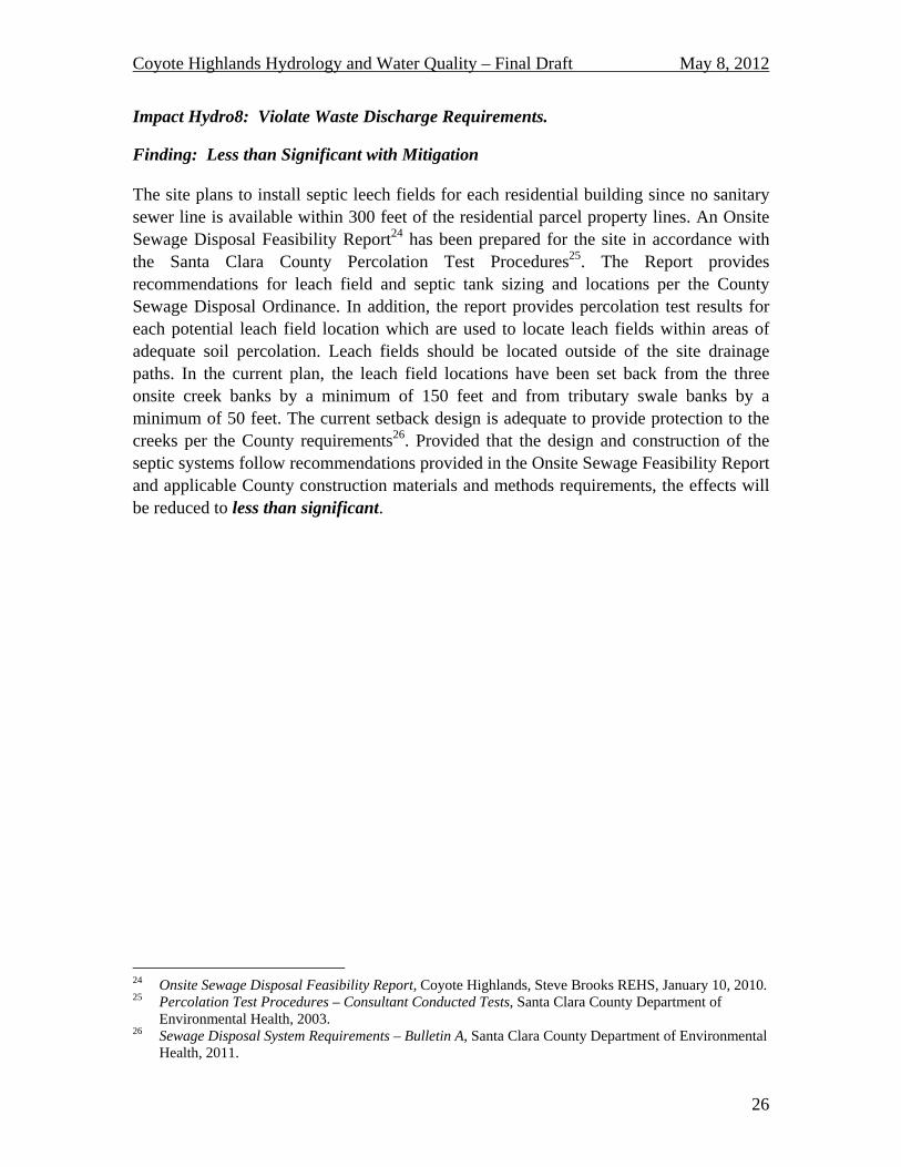
The site plans to install septic leech fields for each residential building since no sanitary sewer line is available within 300 feet of the residential parcel property lines. An Onsite Sewage Disposal Feasibility Report24 has been prepared for the site in accordance with the Santa Clara County Percolation Test Procedures25. The Report provides recommendations for leach field and septic tank sizing and locations per the County Sewage Disposal Ordinance. In addition, the report provides percolation test results for each potential leach field location which are used to locate leach fields within areas of adequate soil percolation. Leach fields should be located outside of the site drainage paths. In the current plan, the leach field locations have been set back from the three onsite creek banks by a minimum of 150 feet and from tributary swale banks by a minimum of 50 feet. The current setback design is adequate to provide protection to the creeks per the County requirements26. Provided that the design and construction of the septic systems follow recommendations provided in the Onsite Sewage Feasibility Report and applicable County construction materials and methods requirements, the effects will be reduced to less than significant.
24 Onsite Sewage Disposal Feasibility Report, Coyote Highlands, Steve Brooks REHS, January 10, 2010. 25 Percolation Test Procedures – Consultant Conducted Tests, Santa Clara County Department of
Environmental Health, 2003. 26 Sewage Disposal System Requirements – Bulletin A, Santa Clara County Department of Environmental
Health, 2011.

Coyote Highlands Hydrology and Water Quality – Final Draft May 8, 2012
27
REFERENCES
1. Association of Bay Area Governments’ (ABAG), Dam Failure Inundation Hazard Map for Morgan Hill, http://www.abag.ca.gov (1995).
2. California Stormwater Quality Association, Best Management Practices Handbook for New Development and Redevelopment, 2004.
3. California Stormwater Quality Association, Best Management Practices Handbook for Construction, 2009.
4. City of Morgan Hill, Engineering Department, Storm Drain Design Standards, http://www.morgan-hill.ca.gov.
5. City of Gilroy, City of Morgan Hill, and County of Santa Clara, Revised Storm Water Management Plan, February 22, 2010.
6. Federal Emergency Management Agency, Flood Control Map Numbers 06085C0464H & 06085C0627H, May 18, 2009.
7. Lawrence Livermore National Laboratories with California State Water Resources Control Board, Ground-Water Quality Data in the Monterey and Salinas Valley Basins, California, 2005.
8. Lawrence Livermore National Laboratories with California State Water Resources Control Board, Ground-Water Quality Data in the San Francisco Bay Study Unit, 2007.
9. Santa Clara County, California prepared by Schaaf & Wheeler, Drainage Manual, August 14, 2007.
10. Santa Clara County Department of Environmental Health, Percolation Test Procedures – Consultant Conducted Tests, 2003.
11. Santa Clara County Department of Environmental Health, Sewage Disposal System Requirements – Bulletin A, 2011.
12. Santa Clara Valley Urban Runoff Pollution Prevention Program (SCVURPPP), C.3 Stormwater Handbook, May 2006.
13. Santa Clara Valley Water District, Anderson Dam EAP Map 2003 Flood Inundation Map, Sheet 7, 2003.
14. Santa Clara Valley Water District, Groundwater Vulnerability Study, Santa Clara County, California, October 2010.
15. Santa Clara Valley Water District, Urban Water Management Plan, 2010. 16. State of California Department of Conservation, Landslide Inventory Map, Mt.
Sizer Quadrangle, 2006. 17. State of California Department of Water Resources, California's Groundwater
Bulletin 118, 3-3.01, Feb. 27, 2004 18. State Water Resources Control Board, Water Board Map,
http://www.waterboards.ca.gov/waterboards_map.shtml, (2010). 19. State Water Resources Control Board, 2009-0009-DWQ Construction General
Permit, July 1, 2010. 20. United States Geological Survey, Mt. Sizer and Gilroy Quadrangle Maps. 21. Web Soil Survey – National Cooperative Soil Survey, Natural Resources
Conservation Service, Soil Map – Eastern Santa Clara Area, California, http://websoilsurvey.nrcs.usda.gov (July 27, 2010).


![[Hydrology] groundwater hydrology david k. todd (2005)](https://static.fdocuments.in/doc/165x107/55a8e6001a28ab6c2f8b4687/hydrology-groundwater-hydrology-david-k-todd-2005-55b0d9a792c06.jpg)


![[hydrology] groundwater hydrology - david k. todd (2005).pdf](https://static.fdocuments.in/doc/165x107/577c77961a28abe0548cb0b1/hydrology-groundwater-hydrology-david-k-todd-2005pdf.jpg)


