Hydrokraft Open Loop Piston Pumps - … · 4 EATON VickersHydrokraft Open Loop Piston Pumps...
56
Hydrokraft Open Loop Piston Pumps Technical Catalog PVX
Transcript of Hydrokraft Open Loop Piston Pumps - … · 4 EATON VickersHydrokraft Open Loop Piston Pumps...
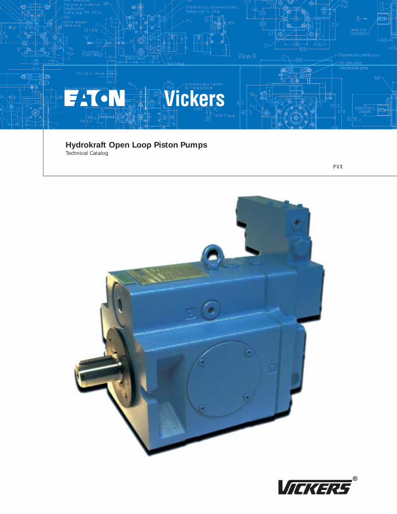
Hydrokraft Open Loop Piston PumpsTechnical Catalog
PVX
2 EATON Vickers Hydrokraft Open Loop Piston Pumps V-PUPI-TM004-E March 2003
Table of Contents
Introduction . . . . . . . . . . . . . . . . . . . . . . . . . . . . . . . . . . . . . . . . . . . . . . . . . . . . . . . . . . . . . . . . . . . . . . . . . . 4
Model Code
Form Page . . . . . . . . . . . . . . . . . . . . . . . . . . . . . . . . . . . . . . . . . . . . . . . . . . . . . . . . . . . . . . . . . . . . . . . . 5
Basic Pumps . . . . . . . . . . . . . . . . . . . . . . . . . . . . . . . . . . . . . . . . . . . . . . . . . . . . . . . . . . . . . . . . . . . . . . 6
No Control . . . . . . . . . . . . . . . . . . . . . . . . . . . . . . . . . . . . . . . . . . . . . . . . . . . . . . . . . . . . . . . . . . . . . . . . 7
DF Control. . . . . . . . . . . . . . . . . . . . . . . . . . . . . . . . . . . . . . . . . . . . . . . . . . . . . . . . . . . . . . . . . . . . . . . . . 8
DQ Control . . . . . . . . . . . . . . . . . . . . . . . . . . . . . . . . . . . . . . . . . . . . . . . . . . . . . . . . . . . . . . . . . . . . . . . . 9
LR Control . . . . . . . . . . . . . . . . . . . . . . . . . . . . . . . . . . . . . . . . . . . . . . . . . . . . . . . . . . . . . . . . . . . . . . . 10
ES Control . . . . . . . . . . . . . . . . . . . . . . . . . . . . . . . . . . . . . . . . . . . . . . . . . . . . . . . . . . . . . . . . . . . . . . . 11
HG Control . . . . . . . . . . . . . . . . . . . . . . . . . . . . . . . . . . . . . . . . . . . . . . . . . . . . . . . . . . . . . . . . . . . . . . . 12
FE Control . . . . . . . . . . . . . . . . . . . . . . . . . . . . . . . . . . . . . . . . . . . . . . . . . . . . . . . . . . . . . . . . . . . . . . . 13
DP Control . . . . . . . . . . . . . . . . . . . . . . . . . . . . . . . . . . . . . . . . . . . . . . . . . . . . . . . . . . . . . . . . . . . . . . . 14
SP Control . . . . . . . . . . . . . . . . . . . . . . . . . . . . . . . . . . . . . . . . . . . . . . . . . . . . . . . . . . . . . . . . . . . . . . . 15
Special Features . . . . . . . . . . . . . . . . . . . . . . . . . . . . . . . . . . . . . . . . . . . . . . . . . . . . . . . . . . . . . . . . . . . 16
Combination Units . . . . . . . . . . . . . . . . . . . . . . . . . . . . . . . . . . . . . . . . . . . . . . . . . . . . . . . . . . . . . . . . . 17
Examples for Combination units . . . . . . . . . . . . . . . . . . . . . . . . . . . . . . . . . . . . . . . . . . . . . . . . . . . . . 18
Pump Specifications
US . . . . . . . . . . . . . . . . . . . . . . . . . . . . . . . . . . . . . . . . . . . . . . . . . . . . . . . . . . . . . . . . . . . . . . . . . . . . . . 19
Metric . . . . . . . . . . . . . . . . . . . . . . . . . . . . . . . . . . . . . . . . . . . . . . . . . . . . . . . . . . . . . . . . . . . . . . . . . . . 20
Performance Curves
Performance Curves, Outlet Flow & Inlet Power, Shaft Input Power, 066 to 250 Series. . . . . . . . . 21
Operating Data: Theoretical Bearing Life . . . . . . . . . . . . . . . . . . . . . . . . . . . . . . . . . . . . . . . . . . . . . . . 22
Operating Data: Typical Drain Flow . . . . . . . . . . . . . . . . . . . . . . . . . . . . . . . . . . . . . . . . . . . . . . . . . . . 23
Controls
DF, LR Pressure Compensator/Power Control . . . . . . . . . . . . . . . . . . . . . . . . . . . . . . . . . . . . . . . . . . . 24
DQ Mooring Control . . . . . . . . . . . . . . . . . . . . . . . . . . . . . . . . . . . . . . . . . . . . . . . . . . . . . . . . . . . . . . . 27
FE, HG Manual Displacement Adj. Control . . . . . . . . . . . . . . . . . . . . . . . . . . . . . . . . . . . . . . . . . . . . . 28
Electric Motor Displacement Control ES . . . . . . . . . . . . . . . . . . . . . . . . . . . . . . . . . . . . . . . . . . . . . . . 29
Pressure Signal Displacement Control DP. . . . . . . . . . . . . . . . . . . . . . . . . . . . . . . . . . . . . . . . . . . . . . 30
Proportional Valve Displacement Control SP. . . . . . . . . . . . . . . . . . . . . . . . . . . . . . . . . . . . . . . . . . . . 31
3EATON Vickers Hydrokraft Open Loop Piston Pumps V-PUPI-TM004-E March 2003
Table of Contents(cont.)
Pump Dimensions *
PFXS 066. . . . . . . . . . . . . . . . . . . . . . . . . . . . . . . . . . . . . . . . . . . . . . . . . . . . . . . . . . . . . . . . . . . . . . . . . 32
PFXS 090. . . . . . . . . . . . . . . . . . . . . . . . . . . . . . . . . . . . . . . . . . . . . . . . . . . . . . . . . . . . . . . . . . . . . . . . . 33
PFXS 130. . . . . . . . . . . . . . . . . . . . . . . . . . . . . . . . . . . . . . . . . . . . . . . . . . . . . . . . . . . . . . . . . . . . . . . . . 34
PFXS 180. . . . . . . . . . . . . . . . . . . . . . . . . . . . . . . . . . . . . . . . . . . . . . . . . . . . . . . . . . . . . . . . . . . . . . . . . 35
PFXS 250. . . . . . . . . . . . . . . . . . . . . . . . . . . . . . . . . . . . . . . . . . . . . . . . . . . . . . . . . . . . . . . . . . . . . . . . . 36
PVXS 066 - 250 DF, Two Stage Pilot Valve . . . . . . . . . . . . . . . . . . . . . . . . . . . . . . . . . . . . . . . . . . . . . . 38
PVXS 066 - 250 DF, with Load Sensing Valve . . . . . . . . . . . . . . . . . . . . . . . . . . . . . . . . . . . . . . . . . . . 40
PVXS 066 - 250 LR, with Pressure Limiter . . . . . . . . . . . . . . . . . . . . . . . . . . . . . . . . . . . . . . . . . . . . . . 42
PVXS 066 - 250 ES . . . . . . . . . . . . . . . . . . . . . . . . . . . . . . . . . . . . . . . . . . . . . . . . . . . . . . . . . . . . . . . . . 44
PVXS 066 - 250 DP, with Prop. Pilot Valve . . . . . . . . . . . . . . . . . . . . . . . . . . . . . . . . . . . . . . . . . . . . . . 46
PVXS 066 - 250 SP, with Prop. Pilot Valve . . . . . . . . . . . . . . . . . . . . . . . . . . . . . . . . . . . . . . . . . . . . . . 48
Thru - drives . . . . . . . . . . . . . . . . . . . . . . . . . . . . . . . . . . . . . . . . . . . . . . . . . . . . . . . . . . . . . . . . . . . . . . 50
Splined Shaft . . . . . . . . . . . . . . . . . . . . . . . . . . . . . . . . . . . . . . . . . . . . . . . . . . . . . . . . . . . . . . . . . . . . . 51
SAE4 - Bolt Mounting, Installation Data . . . . . . . . . . . . . . . . . . . . . . . . . . . . . . . . . . . . . . . . . . . . . . . 52
Application Data
Fluid Recommendations . . . . . . . . . . . . . . . . . . . . . . . . . . . . . . . . . . . . . . . . . . . . . . . . . . . . . . . . . . . . 53
* Dimensions - PVXS-066 to 250 DQ/HG/FE ask for special drawings.
4 EATON Vickers Hydrokraft Open Loop Piston Pumps V-PUPI-TM004-E March 2003
Introduction
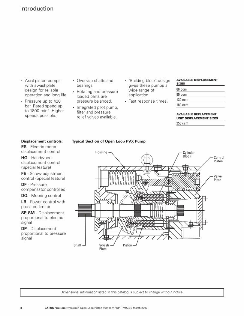
• Axial piston pumpswith swashplatedesign for reliableoperation and long life.
• Pressure up to 420bar. Rated speed up to 1800 min-1. Higherspeeds possible.
• Oversize shafts andbearings.
• Rotating and pressureloaded parts arepressure balanced.
• Integrated pilot pump,filter and pressurerelief valves available.
• "Building block" design gives these pumps a wide range of application.
• Fast response times.
Displacement controls:
ES - Electric motordisplacement controlHG - Handwheeldisplacement control(Special feature)FE - Screw adjustmentcontrol (Special feature)DF - Pressurecompensator controlledDQ - Mooring controlLR - Power control withpressure limiterSP, SM - Displacementproportional to electricsignalDP - Displacementproportional to pressuresignal
Dimensional information listed in this catalog is subject to change without notice.
SwashPlate
Piston Shaft
Housing Cylinder Block
Valve Plate
Control Piston
Typical Section of Open Loop PVX Pump
AVAILABLE DISPLACEMENTSIZES
66 ccm90 ccm130 ccm180 ccm
AVAILABLE REPLACEMENTUNIT DISPLACEMENT SIZES
250 ccm
5EATON Vickers Hydrokraft Open Loop Piston Pumps V-PUPI-TM004-E March 2003
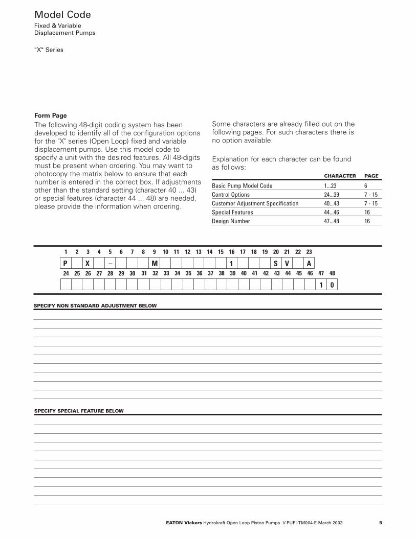
Model CodeFixed & VariableDisplacement Pumps
"X" Series
1 2 3 4 5 6 7 8 9 10 11 12 13 14 15 16 17 18 19 20 21 22 23
M XP – 31 32 33 34 35 36 37 38 39 40 41 42 43 44 45 46 47 48
1
1 0
S V A24 25 26 27 28 29 30
Form Page
The following 48-digit coding system has been developed to identify all of the configuration optionsfor the "X" series (Open Loop) fixed and variable displacement pumps. Use this model code to specify a unit with the desired features. All 48-digitsmust be present when ordering. You may want tophotocopy the matrix below to ensure that eachnumber is entered in the correct box. If adjustmentsother than the standard setting (character 40 ... 43)or special features (character 44 ... 48) are needed,please provide the information when ordering.
Some characters are already filled out on the following pages. For such characters there is no option available.
Explanation for each character can be found as follows:
CHARACTER PAGE
Basic Pump Model Code 1...23 6Control Options 24...39 7 - 15Customer Adjustment Specification 40...43 7 - 15Special Features 44...46 16Design Number 47...48 16
SPECIFY NON STANDARD ADJUSTMENT BELOW
SPECIFY SPECIAL FEATURE BELOW
6 EATON Vickers Hydrokraft Open Loop Piston Pumps V-PUPI-TM004-E March 2003
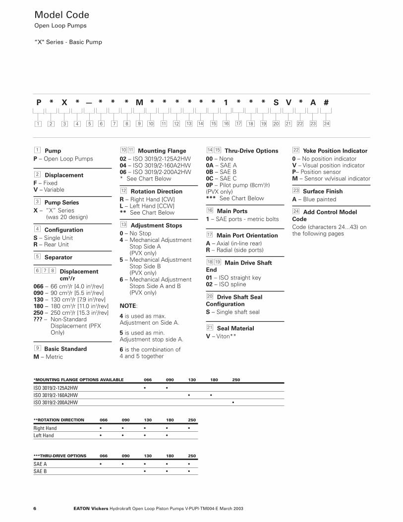
P * X * — * * * M * * * * * * 1 * * * S V * A #
Model Code Open Loop Pumps
“X" Series - Basic Pump
Pump
P – Open Loop Pumps
Displacement
F – FixedV – Variable
Pump Series
X – “X” Series (was 20 design)
Configuration
S – Single UnitR – Rear Unit
Separator
Displacement
cm3/r
066 – 66 cm3/r [4.0 in3/rev]090 – 90 cm3/r [5.5 in3/rev]130 – 130 cm3/r [7.9 in3/rev]180 – 180 cm3/r [11.0 in3/rev]250 – 250 cm3/r [15.3 in3/rev]??? – Non-Standard
Displacement (PFX Only)
Basic Standard
M – Metric
Mounting Flange
02 – ISO 3019/2-125A2HW04 – ISO 3019/2-160A2HW06 – ISO 3019/2-200A2HW* See Chart Below
Rotation Direction
R – Right Hand [CW]L – Left Hand [CCW]** See Chart Below
Adjustment Stops
0 – No Stop4 – Mechanical Adjustment
Stop Side A (PVX only)
5 – Mechanical AdjustmentStop Side B (PVX only)
6 – Mechanical AdjustmentStops Side A and B (PVX only)
NOTE:
4 is used as max. Adjustment on Side A.
5 is used as min. Adjustment stop side A.
6 is the combination of 4 and 5 together
Thru-Drive Options
00 – None0A – SAE A0B – SAE B0C – SAE C0P – Pilot pump (8cm3/r) (PVX only)*** See Chart Below
Main Ports
1 – SAE ports - metric bolts
Main Port Orientation
A – Axial (in-line rear)R – Radial (side ports)
Main Drive Shaft
End
01 – ISO straight key02 – ISO spline
Drive Shaft Seal
Configuration
S – Single shaft seal
Seal Material
V – Viton**
Yoke Position Indicator
0 – No position indicatorV – Visual position indicatorP– Position sensorM – Sensor w/visual indicator
Surface Finish
A – Blue painted
Add Control Model
Code
Code (characters 24...43) onthe following pages
24
23
22
21
20
1918
17
16
1514
13
12
1110
9
876
5
4
3
2
1
2 3 4 5 186 7 8 9 10 11 12 13 14 15 16 17 19 20 21 22 231 24
*MOUNTING FLANGE OPTIONS AVAILABLE 066 090 130 180 250
ISO 3019/2-125A2HW • •ISO 3019/2-160A2HW • •ISO 3019/2-200A2HW •
**ROTATION DIRECTION 066 090 130 180 250
Right Hand • • • • •Left Hand • • • •
***THRU-DRIVE OPTIONS 066 090 130 180 250
SAE A • • • • •SAE B • • •
7EATON Vickers Hydrokraft Open Loop Piston Pumps V-PUPI-TM004-E March 2003
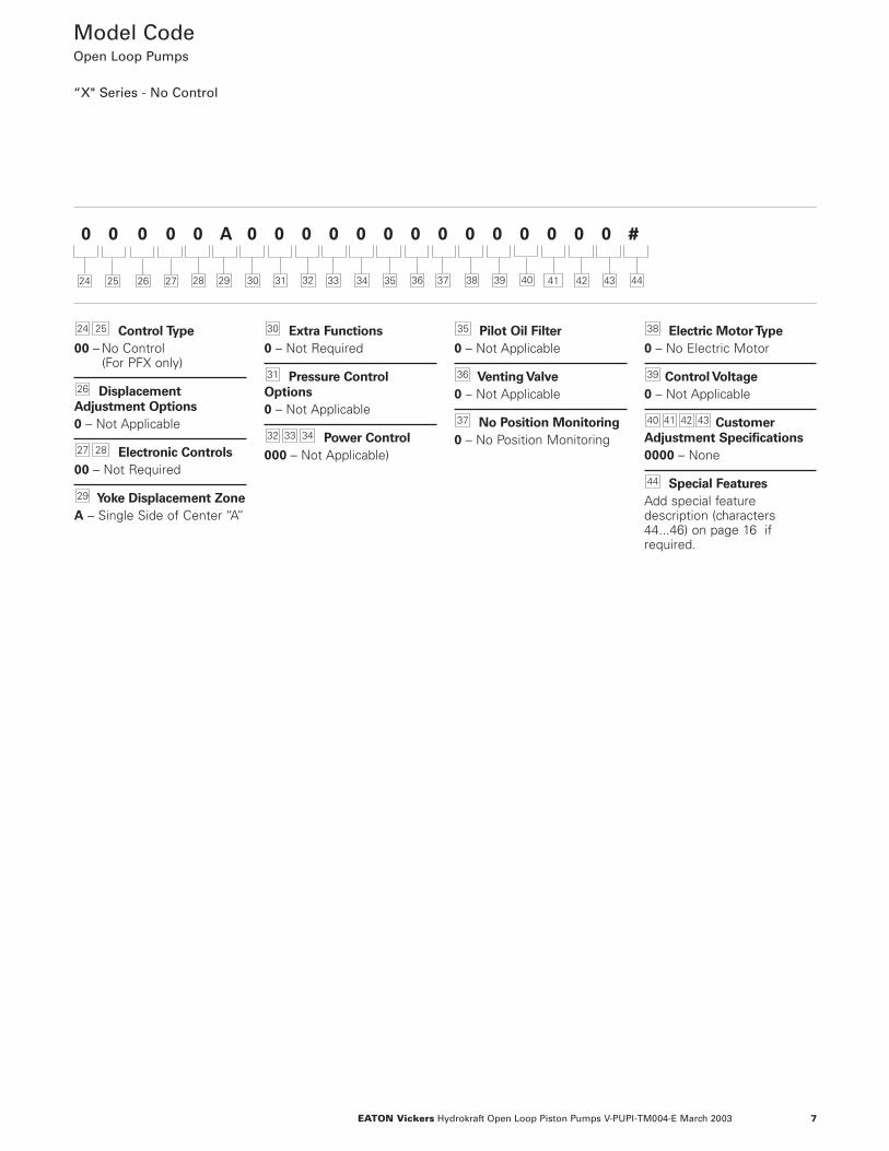
Control Type
00 – No Control (For PFX only)
Displacement
Adjustment Options
0 – Not Applicable
Electronic Controls
00 – Not Required
Yoke Displacement Zone
A – Single Side of Center “A”
Extra Functions
0 – Not Required
Pressure Control
Options
0 – Not Applicable
Power Control
000 – Not Applicable)
Pilot Oil Filter
0 – Not Applicable
Venting Valve
0 – Not Applicable
No Position Monitoring
0 – No Position Monitoring
Electric Motor Type
0 – No Electric Motor
Control Voltage
0 – Not Applicable
Customer
Adjustment Specifications
0000 – None
Special Features
Add special featuredescription (characters44...46) on page 16 ifrequired.
44
43424140
39
38
37
36
35
343332
31
30
29
2827
26
2524
25 26 27
0 0 0 0 0 A 0 0 0 0 0 0 0 0 0 0 0 0 0 0 #
28 4129 30 31 32 33 34 35 36 37 38 39 40 42 43 4424
Model Code Open Loop Pumps
“X" Series - No Control
8 EATON Vickers Hydrokraft Open Loop Piston Pumps V-PUPI-TM004-E March 2003
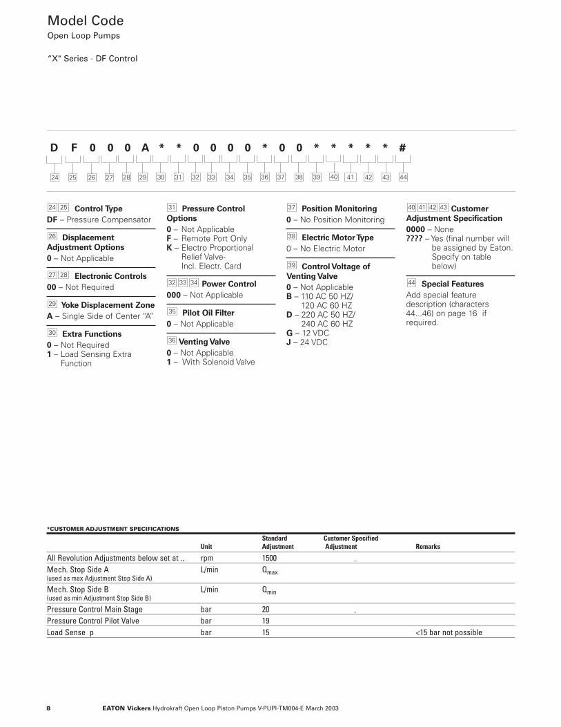
Control Type
DF – Pressure Compensator
Displacement
Adjustment Options
0 – Not Applicable
Electronic Controls
00 – Not Required
Yoke Displacement Zone
A – Single Side of Center “A”
Extra Functions
0 – Not Required1 – Load Sensing Extra
Function
Pressure Control
Options
0 – Not Applicable F – Remote Port OnlyK – Electro Proportional
Relief Valve-Incl. Electr. Card
Power Control
000 – Not Applicable
Pilot Oil Filter
0 – Not Applicable
Venting Valve
0 – Not Applicable 1 – With Solenoid Valve
Position Monitoring
0 – No Position Monitoring
Electric Motor Type
0 – No Electric Motor
Control Voltage of
Venting Valve
0 – Not ApplicableB – 110 AC 50 HZ/
120 AC 60 HZD – 220 AC 50 HZ/
240 AC 60 HZG – 12 VDCJ – 24 VDC
Customer
Adjustment Specification
0000 – None???? – Yes (final number will
be assigned by Eaton.Specify on tablebelow)
Special Features
Add special featuredescription (characters44...46) on page 16 ifrequired.
44
43424140
39
38
37
36
35
343332
31
30
29
2827
26
2524
Model Code Open Loop Pumps
“X" Series - DF Control
25 26 27
D F 0 0 0 A * * 0 0 0 0 * 0 0 * * * * * #
28 4129 30 31 32 33 34 35 36 37 38 39 40 42 43 4424
*CUSTOMER ADJUSTMENT SPECIFICATIONS
Standard Customer SpecifiedUnit Adjustment Adjustment Remarks
All Revolution Adjustments below set at .. rpm 1500 -Mech. Stop Side A L/min Qmax(used as max Adjustment Stop Side A)
Mech. Stop Side B L/min Qmin(used as min Adjustment Stop Side B)
Pressure Control Main Stage bar 20 -Pressure Control Pilot Valve bar 19Load Sense p bar 15 <15 bar not possible
9EATON Vickers Hydrokraft Open Loop Piston Pumps V-PUPI-TM004-E March 2003
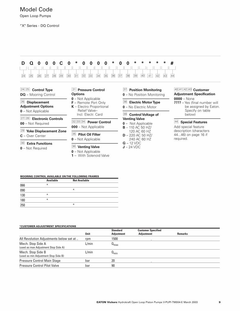
*CUSTOMER ADJUSTMENT SPECIFICATIONS
Standard Customer SpecifiedUnit Adjustment Adjustment Remarks
All Revolution Adjustments below set at .. rpm 1500 -Mech. Stop Side A L/min Qmax(used as max Adjustment Stop Side A)
Mech. Stop Side B L/min Qmin(used as min Adjustment Stop Side B)
Pressure Control Main Stage bar 20 -Pressure Control Pilot Valve bar 90
Control Type
DQ – Mooring Control
Displacement
Adjustment Options
0 – Not Applicable
Electronic Controls
00 – Not Required
Yoke Displacement Zone
C – Over Center
Extra Functions
0 – Not Required
Pressure Control
Options
0 – Not Applicable F – Remote Port OnlyK – Electro Proportional
Relief Valve–Incl. Electr. Card
Power Control
000 – Not Applicable
Pilot Oil Filter
0 – Not Applicable
Venting Valve
0 – Not Applicable 1 – With Solenoid Valve
Position Monitoring
0 – No Position Monitoring
Electric Motor Type
0 – No Electric Motor
Control Voltage of
Venting Valve
0 – Not ApplicableB – 110 AC 50 HZ/
120 AC 60 HZD – 220 AC 50 HZ/
240 AC 60 HZG – 12 VDCJ – 24 VDC
Customer
Adjustment Specification
0000 – None???? – Yes (final number will
be assigned by Eaton.Specify on tablebelow)
Special Features
Add special featuredescription (characters44...46) on page 16 ifrequired.
44
43424140
39
38
37
36
35
343332
31
30
29
2827
26
2524
Model Code Open Loop Pumps
“X" Series - DQ Control
25 26 27
D Q 0 0 0 C 0 * 0 0 0 0 * 0 0 * * * * * #
28 4129 30 31 32 33 34 35 36 37 38 39 40 42 43 4424
MOORING CONTROL AVAILABLE ON THE FOLLOWING FRAMES
Available Not Available
066 *090 *130 *180 *250 *
10 EATON Vickers Hydrokraft Open Loop Piston Pumps V-PUPI-TM004-E March 2003
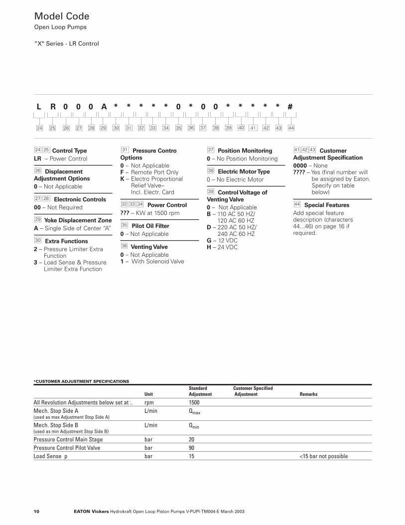
Control Type
LR – Power Control
Displacement
Adjustment Options
0 – Not Applicable
Electronic Controls
00 – Not Required
Yoke Displacement Zone
A – Single Side of Center “A”
Extra Functions
2 – Pressure Limiter ExtraFunction
3 – Load Sense & PressureLimiter Extra Function
Pressure Contro
Options
0 – Not Applicable F – Remote Port OnlyK – Electro Proportional
Relief Valve–Incl. Electr. Card
Power Control
??? – KW at 1500 rpm
Pilot Oil Filter
0 – Not Applicable
Venting Valve
0 – Not Applicable 1 – With Solenoid Valve
Position Monitoring
0 – No Position Monitoring
Electric Motor Type
0 – No Electric Motor
Control Voltage of
Venting Valve
0 – Not ApplicableB – 110 AC 50 HZ/
120 AC 60 HZD – 220 AC 50 HZ/
240 AC 60 HZG – 12 VDCH – 24 VDC
Customer
Adjustment Specification
0000 – None???? – Yes (final number will
be assigned by Eaton.Specify on tablebelow)
Special Features
Add special featuredescription (characters44...46) on page 16 ifrequired.
44
434241
39
38
37
36
35
343332
31
30
29
2827
26
2524
Model Code Open Loop Pumps
“X" Series - LR Control
25 26 27
L R 0 0 0 A * * * * * 0 * 0 0 * * * * * #
28 4129 30 31 32 33 34 35 36 37 38 39 40 42 43 4424
*CUSTOMER ADJUSTMENT SPECIFICATIONS
Standard Customer SpecifiedUnit Adjustment Adjustment Remarks
All Revolution Adjustments below set at .. rpm 1500Mech. Stop Side A L/min Qmax(used as max Adjustment Stop Side A)
Mech. Stop Side B L/min Qmin(used as min Adjustment Stop Side B)
Pressure Control Main Stage bar 20Pressure Control Pilot Valve bar 90Load Sense p bar 15 <15 bar not possible
11EATON Vickers Hydrokraft Open Loop Piston Pumps V-PUPI-TM004-E March 2003
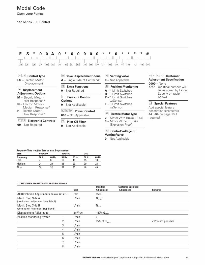
Control Type
ES – Electric MotorDisplacement
Displacement
Adjustment Options
M – Electric Motor - Fast Response*
N – Electric Motor - Medium Response*
P – Electric Motor -Slow Response*
Electronic Controls
00 – Not Required
Yoke Displacement Zone
A – Single Side of Center “A”
Extra Functions
0 – Not Required
Pressure Control
Options
0 – Not Applicable
Power Control
000 – Not Applicable
Pilot Oil Filter
0 – Not Applicable
Venting Valve
0 – Not Applicable
Position Monitoring
A –4 Limit SwitchesB –8 Limit SwitchesP – 4 Limit Switches
w/SensorT – 8 Limit Switches
w/Sensor
Electric Motor Type
2 – Motor With Brake (IP-54) 3 – Motor Without Brake
(Explosion Proof)
Control Voltage of
Venting Valve
0 – Not Applicable
Customer
Adjustment Specification
0000 – None???? – Yes (final number will
be assigned by Eaton.Specify on tablebelow)
Special Features
Add special featuredescription (characters44...46) on page 16 ifrequired.
44
43424140
39
38
37
36
35
343332
31
30
29
2827
26
2524
Model Code Open Loop Pumps
“X" Series - ES Control
25 26 27
E S * 0 0 A 0 * 0 0 0 0 0 * * 0 * * * * #
28 4129 30 31 32 33 34 35 36 37 38 39 40 42 43 4424
**CUSTOMER ADJUSTMENT SPECIFICATIONS
Standard Customer SpecifiedUnit Adjustment Adjustment Remarks
All Revolution Adjustments below set at .. rpm 1500Mech. Stop Side A L/min Qmax(used as max Adjustment Stop Side A)
Mech. Stop Side B L/min Qmin(used as min Adjustment Stop Side B)
Displacement Adjusted to… cm3/rev. ~50% QmaxPosition Monitoring Switch 1 L/min 0
2 L/min 95% of Qmax <95% not possible3 L/min4 L/min5 L/min6 L/min7 L/min8 L/min
Response Time (sec) for Zero to max. DisplacementSIZE 066/090 130/180 250
Frequency 50 Hz 60 Hz 50 Hz 60 Hz 50 Hz 60 HzFast 7 6 18 15 15 13Medium 24 20 35 29 30 25Slow 38 32 54 45 48 40
12 EATON Vickers Hydrokraft Open Loop Piston Pumps V-PUPI-TM004-E March 2003
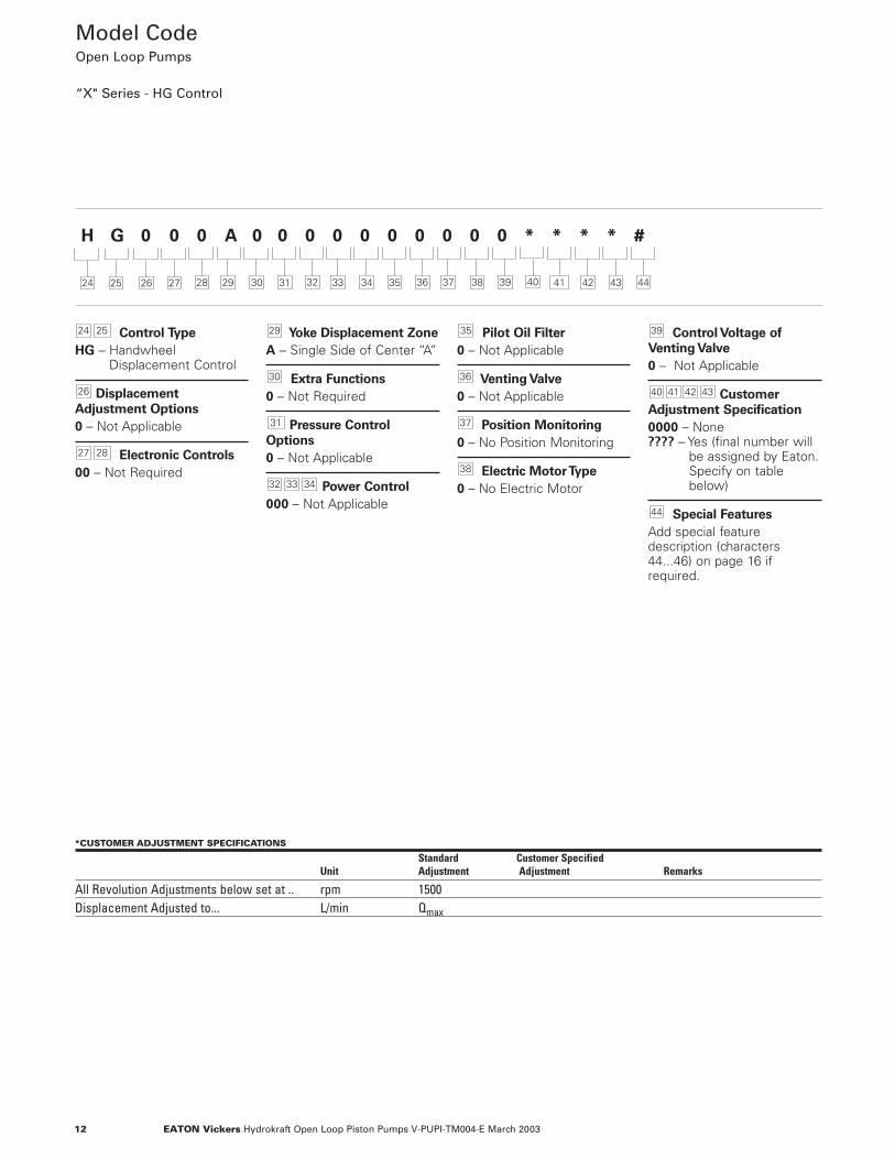
Control Type
HG – HandwheelDisplacement Control
Displacement
Adjustment Options
0 – Not Applicable
Electronic Controls
00 – Not Required
Yoke Displacement Zone
A – Single Side of Center “A”
Extra Functions
0 – Not Required
Pressure Control
Options
0 – Not Applicable
Power Control
000 – Not Applicable
Pilot Oil Filter
0 – Not Applicable
Venting Valve
0 – Not Applicable
Position Monitoring
0 – No Position Monitoring
Electric Motor Type
0 – No Electric Motor
Control Voltage of
Venting Valve
0 – Not Applicable
Customer
Adjustment Specification
0000 – None???? – Yes (final number will
be assigned by Eaton.Specify on tablebelow)
Special Features
Add special featuredescription (characters44...46) on page 16 ifrequired.
44
43424140
39
38
37
36
35
343332
31
30
29
2827
26
2524
Model Code Open Loop Pumps
“X" Series - HG Control
25 26 27
H G 0 0 0 A 0 0 0 0 0 0 0 0 0 0 * * * * #
28 4129 30 31 32 33 34 35 36 37 38 39 40 42 43 4424
*CUSTOMER ADJUSTMENT SPECIFICATIONS
Standard Customer SpecifiedUnit Adjustment Adjustment Remarks
All Revolution Adjustments below set at .. rpm 1500Displacement Adjusted to... L/min Qmax
13EATON Vickers Hydrokraft Open Loop Piston Pumps V-PUPI-TM004-E March 2003
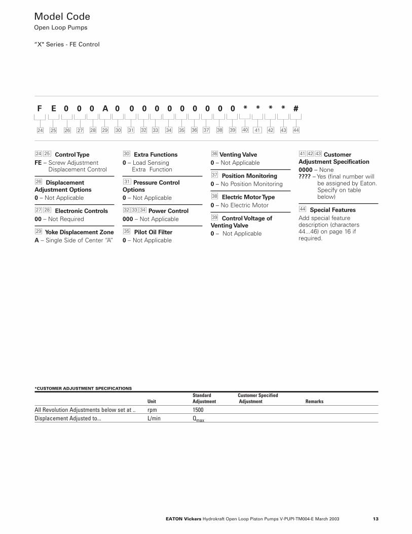
Control Type
FE – Screw AdjustmentDisplacement Control
Displacement
Adjustment Options
0 – Not Applicable
Electronic Controls
00 – Not Required
Yoke Displacement Zone
A – Single Side of Center “A”
Extra Functions
0 – Load Sensing Extra Function
Pressure Control
Options
0 – Not Applicable
Power Control
000 – Not Applicable
Pilot Oil Filter
0 – Not Applicable
Venting Valve
0 – Not Applicable
Position Monitoring
0 – No Position Monitoring
Electric Motor Type
0 – No Electric Motor
Control Voltage of
Venting Valve
0 – Not Applicable
Customer
Adjustment Specification
0000 – None???? – Yes (final number will
be assigned by Eaton.Specify on tablebelow)
Special Features
Add special featuredescription (characters44...46) on page 16 ifrequired.
44
434241
39
38
37
36
35
343332
31
30
29
2827
26
2524
Model Code Open Loop Pumps
“X" Series - FE Control
25 26 27
F E 0 0 0 A 0 0 0 0 0 0 0 0 0 0 * * * * #
28 4129 30 31 32 33 34 35 36 37 38 39 40 42 43 4424
*CUSTOMER ADJUSTMENT SPECIFICATIONS
Standard Customer SpecifiedUnit Adjustment Adjustment Remarks
All Revolution Adjustments below set at .. rpm 1500Displacement Adjusted to... L/min Qmax
14 EATON Vickers Hydrokraft Open Loop Piston Pumps V-PUPI-TM004-E March 2003
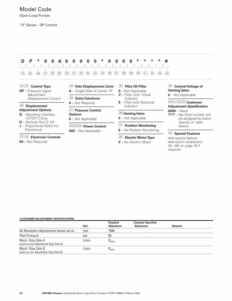
Control Type
DP – Pressure SignalAdjustmentDisplacement Control
Displacement
Adjustment Options
G – Mounting InterfaceCETOP 3 Only
H – Remote Port G 1/4J – Proportional Relief Inc.
Electronics
Electronic Controls
00 – Not Required
Yoke Displacement Zone
A – Single Side of Center “A”
Extra Functions
0 – Not Required
Pressure Control
Options
0 – Not Applicable
Power Control
000 – Not Applicable
Pilot Oil Filter
0 – Not ApplicableV – Filter with Visual
IndicatorE – Filter with Electrical
Indicator
Venting Valve
0 – Not Applicable
Position Monitoring
0 – No Position Monitoring
Electric Motor Type
0 – No Electric Motor
Control Voltage of
Venting Valve
0 – Not Applicable
Customer
Adjustment Specification
0000 – None???? – Yes (final number will
be assigned by Eaton.Specify on tablebelow)
Special Features
Add special featuredescription (characters44...46) on page 16 ifrequired.
44
43424140
39
38
37
36
35
343332
31
30
29
2827
26
2524
Model Code Open Loop Pumps
“X" Series - DP Control
25 26 27
D P * 0 0 A 0 0 0 0 0 * 0 0 0 0 * * * * #
28 4129 30 31 32 33 34 35 36 37 38 39 40 42 43 4424
*CUSTOMER ADJUSTMENT SPECIFICATIONS
Standard Customer SpecifiedUnit Adjustment Adjustment Remarks
All Revolution Adjustments below set at .. rpm 1500 -Pilot Pressure bar 60Mech. Stop Side A L/min Qmax(used as max Adjustment Stop Side A)
Mech. Stop Side B L/min Qmin(used as min Adjustment Stop Side B)
15EATON Vickers Hydrokraft Open Loop Piston Pumps V-PUPI-TM004-E March 2003
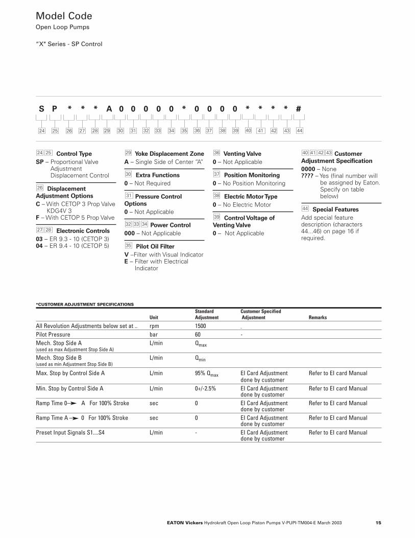
Control Type
SP – Proportional ValveAdjustmentDisplacement Control
Displacement
Adjustment Options
C – With CETOP 3 Prop ValveKDG4V 3
F – With CETOP 5 Prop Valve
Electronic Controls
03 – ER 9.3 - 10 (CETOP 3)04 – ER 9.4 - 10 (CETOP 5)
Yoke Displacement Zone
A – Single Side of Center “A”
Extra Functions
0 – Not Required
Pressure Control
Options
0 – Not Applicable
Power Control
000 – Not Applicable
Pilot Oil Filter
V –Filter with Visual IndicatorE – Filter with Electrical
Indicator
Venting Valve
0 – Not Applicable
Position Monitoring
0 – No Position Monitoring
Electric Motor Type
0 – No Electric Motor
Control Voltage of
Venting Valve
0 – Not Applicable
Customer
Adjustment Specification
0000 – None???? – Yes (final number will
be assigned by Eaton.Specify on tablebelow)
Special Features
Add special featuredescription (characters44...46) on page 16 ifrequired.
44
43424140
39
38
37
36
35
343332
31
30
29
2827
26
2524
Model Code Open Loop Pumps
“X" Series - SP Control
25 26 27
S P * * * A 0 0 0 0 0 * 0 0 0 0 * * * * #
28 4129 30 31 32 33 34 35 36 37 38 39 40 42 43 4424
*CUSTOMER ADJUSTMENT SPECIFICATIONS
Standard Customer SpecifiedUnit Adjustment Adjustment Remarks
All Revolution Adjustments below set at .. rpm 1500 -Pilot Pressure bar 60 -Mech. Stop Side A L/min Qmax(used as max Adjustment Stop Side A)
Mech. Stop Side B L/min Qmin(used as min Adjustment Stop Side B)
Max. Stop by Control Side A L/min 95% Qmax EI Card Adjustment Refer to EI card Manualdone by customer
Min. Stop by Control Side A L/min 0+/-2.5% EI Card Adjustment Refer to EI card Manualdone by customer
Ramp Time 0 A For 100% Stroke sec 0 EI Card Adjustment Refer to EI card Manualdone by customer
Ramp Time A 0 For 100% Stroke sec 0 EI Card Adjustment Refer to EI card Manualdone by customer
Preset Input Signals S1....S4 L/min - EI Card Adjustment Refer to EI card Manualdone by customer
16 EATON Vickers Hydrokraft Open Loop Piston Pumps V-PUPI-TM004-E March 2003
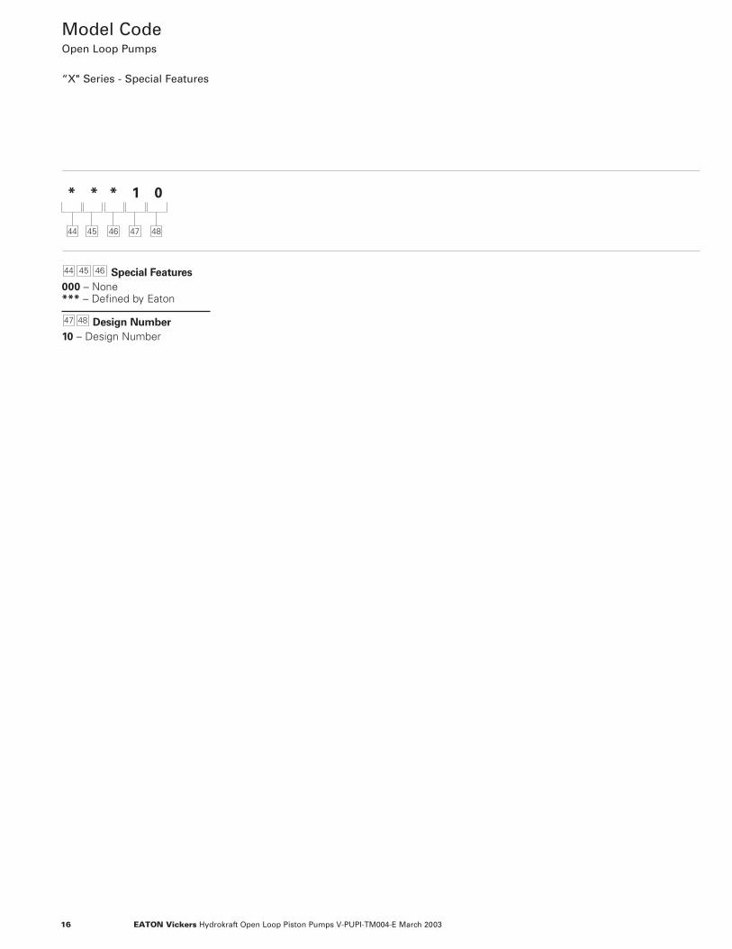
Model Code Open Loop Pumps
“X" Series - Special Features
* * * 1 0
Special Features
000 – None*** – Defined by Eaton
Design Number
10 – Design Number
4847
464544
44 45 46 47 48
17EATON Vickers Hydrokraft Open Loop Piston Pumps V-PUPI-TM004-E March 2003
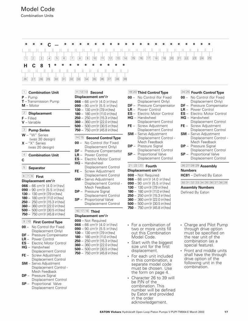
Combination Unit
P – PumpT – Transmission PumpM – Motor
Displacement
F – FilledV – Variable
Pump Series
W – “W” Series (was 30 design)
X – “X” Series (was 20 design)
Combination Unit
C
Separator
First
Displacement cm3/r
066 – 66 cm3/r [4.0 in3/rev]090 – 90 cm3/r [5.5 in3/rev]130 – 130 cm3/r [7.9 in3/rev]180 – 180 cm3/r [11.0 in3/rev]250 – 250 cm3/r [15.3 in3/rev]360 – 360 cm3/r [22.0 in3/rev]500 – 500 cm3/r [30.5 in3/rev]750 – 750 cm3/r [45.8 in3/rev]
First Control Type
00 – No Control (for FixedDisplacement Only)
DF – Pressure CompensatorLR – Power ControlES – Electric Motor ControlHG – Handwheel
Displacement ControlFE – Screw Adjustment
Displacement ControlSM – Servo Adjustment
Displacement Control -Mech Feedback
DP – Pressure SignalDisplacement Control
SP – Proportional ValveDisplacement Control
Second
Displacement cm3/r
066 – 66 cm3/r [4.0 in3/rev]090 – 90 cm3/r [5.5 in3/rev]130 – 130 cm3/r [7.9 in3/rev]180 – 180 cm3/r [11.0 in3/rev]250 – 250 cm3/r [15.3 in3/rev]360 – 360 cm3/r [22.0 in3/rev]500 – 500 cm3/r [30.5 in3/rev]750 – 750 cm3/r [45.8 in3/rev]
Second Control Type
00 – No Control (for FixedDisplacement Only)
DF – Pressure CompensatorLR – Power Control ES – Electric Motor ControlHG – Handwheel
Displacement Control FE – Screw Adjustment
Displacement ControlSM – Servo Adjustment
Displacement Control -Mech Feedback
DP – Pressure SignalDisplacement Control
SP – Proportional ValveDisplacement Control
Third
Displacement cm3/r
000 – Not Required066 – 66 cm3/r [4.0 in3/rev]090 – 90 cm3/r [5.5 in3/rev]130 – 130 cm3/r [7.9 in3/rev]180 – 180 cm3/r [11.0 in3/rev]250 – 250 cm3/r [15.3 in3/rev]360 – 360 cm3/r [22.0 in3/rev]500 – 500 cm3/r [30.5 in3/rev]750 – 750 cm3/r [45.8 in3/rev]
Third Control Type
00 – No Control (for FixedDisplacement Only)
DF – Pressure CompensatorLR – Power ControlES – Electric Motor Control HG – Handwheel
Displacement ControlFE – Screw Adjustment
Displacement ControlSM – Servo Adjustment
Displacement Control -Mech Feedback
DP – Pressure SignalDisplacement Control
SP – Proportional ValveDisplacement Control
Fourth
Displacement cm3/r
000 – Not Required066 – 66 cm3/r [4.0 in3/rev]090 – 90 cm3/r [5.5 in3/rev]130 – 130 cm3/r [7.9 in3/rev]180 – 180 cm3/r [11.0 in3/rev]250 – 250 cm3/r [15.3 in3/rev]360 – 360 cm3/r [22.0 in3/rev]500 – 500 cm3/r [30.5 in3/rev]750 – 750 cm3/r [45.8 in3/rev]
Fourth Control Type
00 – No Control (for FixedDisplacement Only)
DF – Pressure CompensatorLR – Power Control ES – Electric Motor ControlHG – Handwheel
Displacement ControlFE – Screw Adjustment
Displacement Control SM – Servo Adjustment
Displacement Control -Mech Feedback
DP – Pressure SignalDisplacement Control
SP – Proportional ValveDisplacement Control
Assembly
Numbers
HC81 – Defined By Eaton
Assembly Numbers
Defined By Eaton
39383736353433323130
29282726
2524
232221
2019
18 17 16
1514
131211
109
8 7 6
5
4
3
2
1
Model CodeCombination Units
• For a combination oftwo or more units fillout this CombinationModel Code.
• Start with the biggestsize unit for the firstdisplacement.
• For each unit includedin this combination, aseparate model codemust be chosen. Usethe form on page 4.
• Character 26 to 39 willbe P/N of thecombination. Thisnumber will be definedby Eaton and providedin the orderacknowledgement.
• Charge and Pilot Pumpthrough drive optionmust be specified onthe rear unit of thecombination (as aspecial feature).
• Front and middle unitsshall have the throughdrive option of thefollowing unit in thecombination.
2 3 4
* * * C — * * * * * * * * * * * * * * * * * * * *
1 5 186 7 8 9 10 11 12 13 14 15 16 17
26
19 20 21 22 23 24 25
27 28 29 30 31 32 33 34 35 36 37 38 39
H C 8 1 * * * * * * * * * *
18 EATON Vickers Hydrokraft Open Loop Piston Pumps V-PUPI-TM004-E March 2003
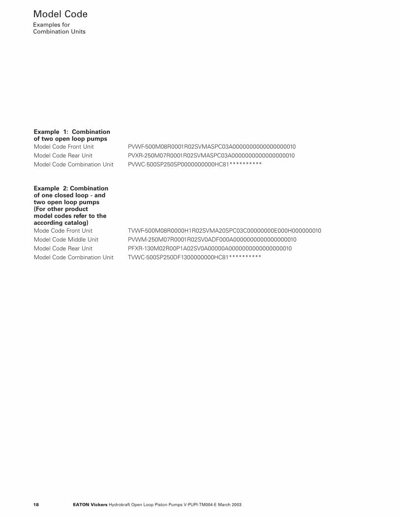
Model CodeExamples for Combination Units
Example 1: Combination of two open loop pumps
Model Code Front Unit PVWF-500M08R0001R02SVMASPC03A0000000000000000010
Model Code Rear Unit PVXR-250M07R0001R02SVMASPC03A0000000000000000010
Model Code Combination Unit PVWC-500SP250SP0000000000HC81**********
Example 2: Combination of one closed loop - and two open loop pumps(For other product model codes refer to the according catalog)
Mode Code Front Unit TVWF-500M08R0000H1R02SVMA20SPC03C00000000E000H000000010
Model Code Middle Unit PVWM-250M07R0001R02SV0ADF000A0000000000000000010
Model Code Rear Unit PFXR-130M02R00P1A02SV0A00000A0000000000000000010
Model Code Combination Unit TVWC-500SP250DF1300000000HC81**********
19EATON Vickers Hydrokraft Open Loop Piston Pumps V-PUPI-TM004-E March 2003
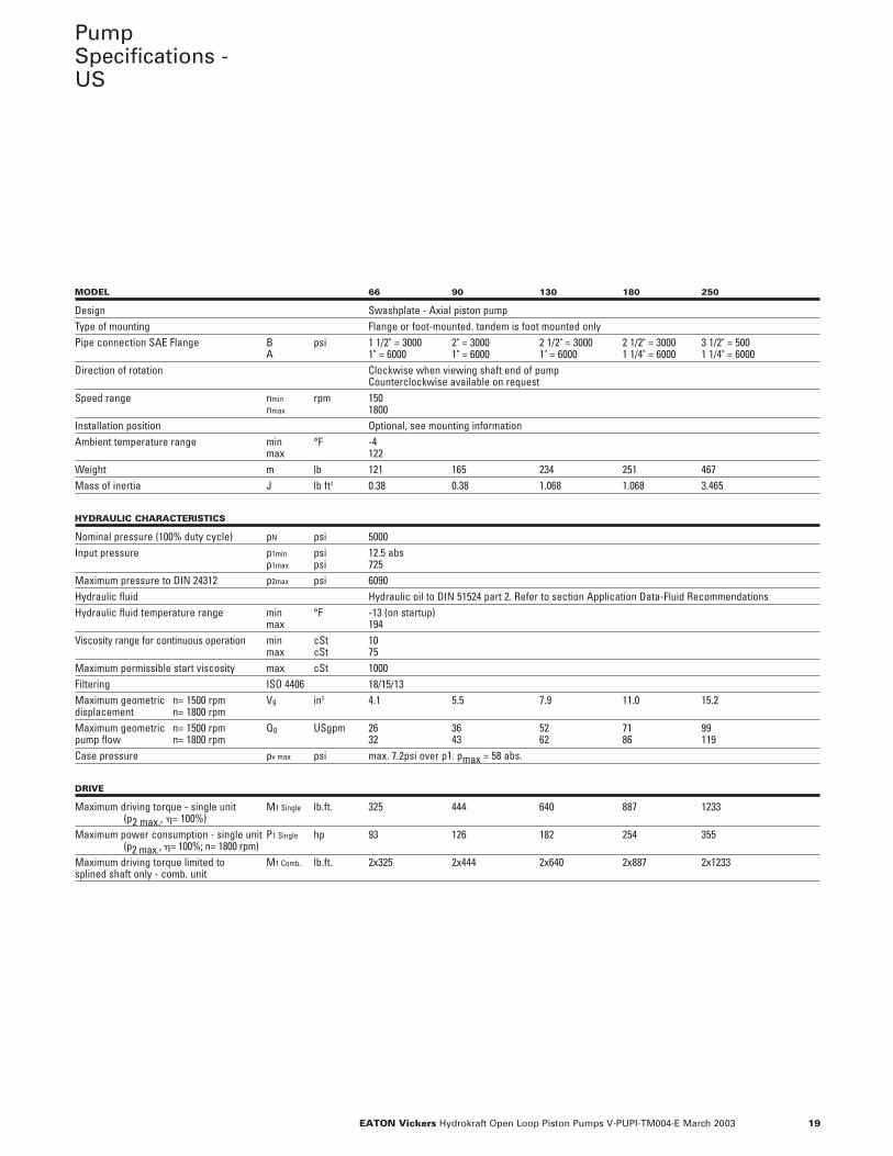
PumpSpecifications -US
MODEL 66 90 130 180 250
Design Swashplate - Axial piston pumpType of mounting Flange or foot-mounted. tandem is foot mounted onlyPipe connection SAE Flange B psi 1 1/2" = 3000 2" = 3000 2 1/2" = 3000 2 1/2" = 3000 3 1/2" = 500
A 1" = 6000 1" = 6000 1" = 6000 1 1/4" = 6000 1 1/4" = 6000Direction of rotation Clockwise when viewing shaft end of pump
Counterclockwise available on requestSpeed range nmin rpm 150
nmax 1800Installation position Optional, see mounting informationAmbient temperature range min °F -4
max 122Weight m lb 121 165 234 251 467 Mass of inertia J lb ft2 0.38 0.38 1.068 1.068 3.465
HYDRAULIC CHARACTERISTICS
Nominal pressure (100% duty cycle) pN psi 5000 Input pressure p1min psi 12.5 abs
p1max psi 725 Maximum pressure to DIN 24312 p2max psi 6090 Hydraulic fluid Hydraulic oil to DIN 51524 part 2. Refer to section Application Data-Fluid RecommendationsHydraulic fluid temperature range min °F -13 (on startup)
max 194 Viscosity range for continuous operation min cSt 10
max cSt 75Maximum permissible start viscosity max cSt 1000Filtering ISO 4406 18/15/13Maximum geometric n= 1500 rpm Vg in3 4.1 5.5 7.9 11.0 15.2displacement n= 1800 rpmMaximum geometric n= 1500 rpm Qg USgpm 26 36 52 71 99 pump flow n= 1800 rpm 32 43 62 86 119 Case pressure pv max psi max. 7.2psi over p1. pmax = 58 abs.
DRIVE
Maximum driving torque - single unit M1 Single lb.ft. 325 444 640 887 1233 (p2 max., �= 100%)
Maximum power consumption - single unit P1 Single hp 93 126 182 254 355(p2 max., �= 100%; n= 1800 rpm)
Maximum driving torque limited to M1 Comb. lb.ft. 2x325 2x444 2x640 2x887 2x1233splined shaft only - comb. unit
20 EATON Vickers Hydrokraft Open Loop Piston Pumps V-PUPI-TM004-E March 2003
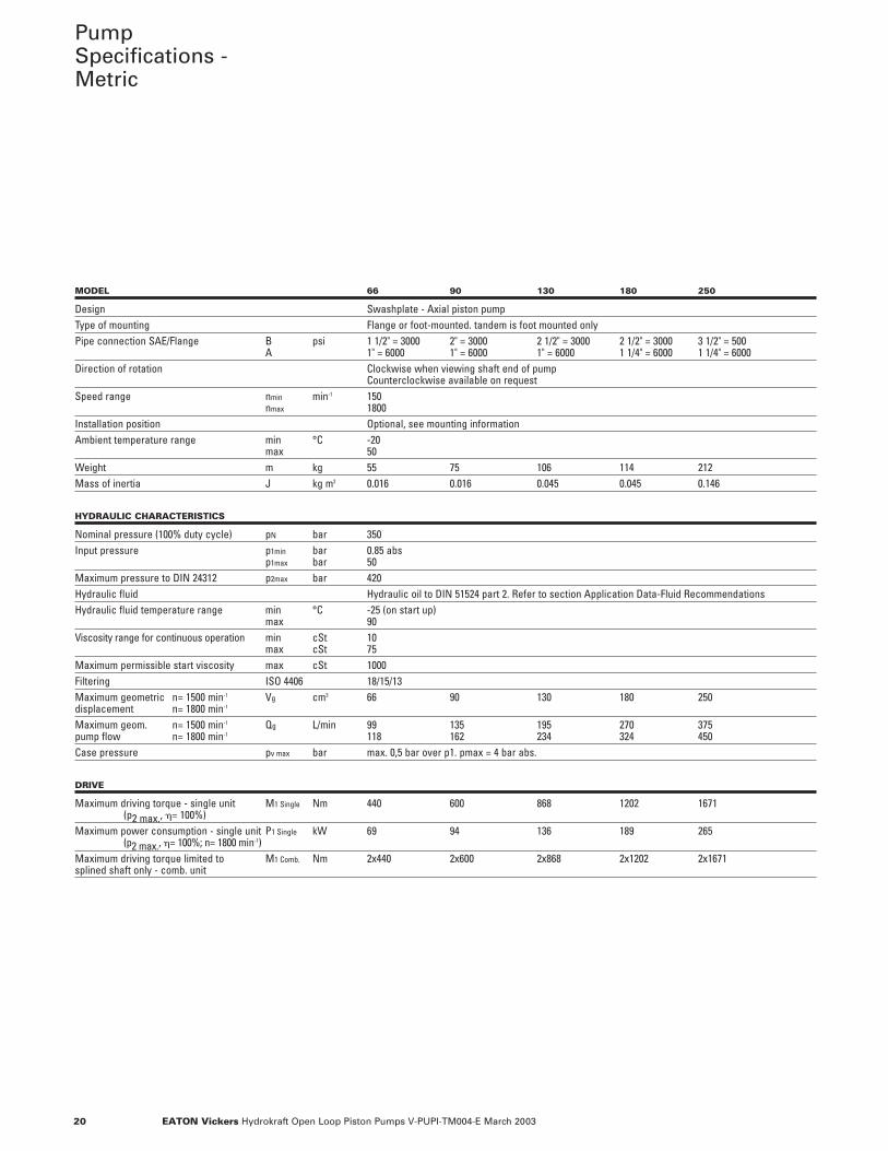
PumpSpecifications -Metric
MODEL 66 90 130 180 250
Design Swashplate - Axial piston pumpType of mounting Flange or foot-mounted. tandem is foot mounted onlyPipe connection SAE/Flange B psi 1 1/2" = 3000 2" = 3000 2 1/2" = 3000 2 1/2" = 3000 3 1/2" = 500
A 1" = 6000 1" = 6000 1" = 6000 1 1/4" = 6000 1 1/4" = 6000Direction of rotation Clockwise when viewing shaft end of pump
Counterclockwise available on requestSpeed range nmin min-1 150
nmax 1800Installation position Optional, see mounting informationAmbient temperature range min °C -20
max 50Weight m kg 55 75 106 114 212Mass of inertia J kg m2 0.016 0.016 0.045 0.045 0.146
HYDRAULIC CHARACTERISTICS
Nominal pressure (100% duty cycle) pN bar 350Input pressure p1min bar 0.85 abs
p1max bar 50Maximum pressure to DIN 24312 p2max bar 420Hydraulic fluid Hydraulic oil to DIN 51524 part 2. Refer to section Application Data-Fluid RecommendationsHydraulic fluid temperature range min °C -25 (on start up)
max 90Viscosity range for continuous operation min cSt 10
max cSt 75Maximum permissible start viscosity max cSt 1000Filtering ISO 4406 18/15/13Maximum geometric n= 1500 min-1 Vg cm3 66 90 130 180 250displacement n= 1800 min-1
Maximum geom. n= 1500 min-1 Qg L/min 99 135 195 270 375pump flow n= 1800 min-1 118 162 234 324 450Case pressure pv max bar max. 0,5 bar over p1. pmax = 4 bar abs.
DRIVE
Maximum driving torque - single unit M1 Single Nm 440 600 868 1202 1671(p2 max., �= 100%)
Maximum power consumption - single unit P1 Single kW 69 94 136 189 265(p2 max., �= 100%; n= 1800 min-1)
Maximum driving torque limited to M1 Comb. Nm 2x440 2x600 2x868 2x1202 2x1671splined shaft only - comb. unit
21EATON Vickers Hydrokraft Open Loop Piston Pumps V-PUPI-TM004-E March 2003
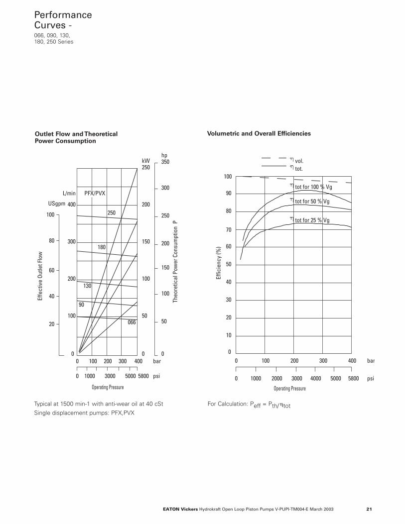
PerformanceCurves -066, 090, 130,180, 250 Series
Theo
retic
al P
ower
Con
sum
ptio
n P
0 100 200 300 400 bar0
400
0 1000 3000 5000 5800 psi
300
200
100
0
50
100
150
200
L/min
250kW
Operating Pressure
PFX/PVX
0
50
150
200
250
350hp
300
10040
60
80
100
USgpm
20
250
180
130
90
066
Effe
ctiv
e Ou
tlet F
low
0 100 200 300 400 bar
100
50
0 1000 2000 3000 4000 5000 5800 psi
Effic
ienc
y (%
)
tot.vol.
Operating Pressure
90
80
70
60
40
30
20
10
0
tot for 100 % Vg
tot for 50 % Vg
tot for 25 % Vg
Outlet Flow and TheoreticalPower Consumption
Volumetric and Overall Efficiencies
Typical at 1500 min-1 with anti-wear oil at 40 cSt
Single displacement pumps: PFX,PVX
For Calculation: Peff = Pth/�tot
50 100 200 300 400bar
725psi
Basi
c Ra
ting
Life
L10
[h]
1450 2900 4350 5800
3 x 10³
410
510Pump size 090
Operating Pressure
1800 min
1500 min
1000 min -1
-1
-1
50 100 200 300 400bar
725psi
Basi
c Ra
ting
Life
L10
[h]
1450 2900 4350 5800
3 x 10³
410
510Pump size 130
Operating Pressure
1800 min
1500 min
1000 min-1
-1
-1
50 100 200 300 400bar
725psi
Basi
c Ra
ting
Life
L10
[h]
1450 2900 4350 5800
3 x 10³
410
510Pump size 180
Operating Pressure
1800 min
1500 min
1000 min -1
-1
-1
50 100 200 300 400bar
725psi
Basi
c Ra
ting
Life
L10
[h]
1450 2900 4350 5800
3 x 10³
410
510Pump size 066
Operating Pressure
1800 min
1500 min
1000 min-1
-1
-1
50 100 200 300 400bar
725psi
Basi
c Ra
ting
Life
L10
[h]
1450 2900 4350 5800
3 x 10 3
410
510Pump size 250
Operating Pressure
1800 min
1500 min
1000 min -1
-1
-1
22 EATON Vickers Hydrokraft Open Loop Piston Pumps V-PUPI-TM004-E March 2003
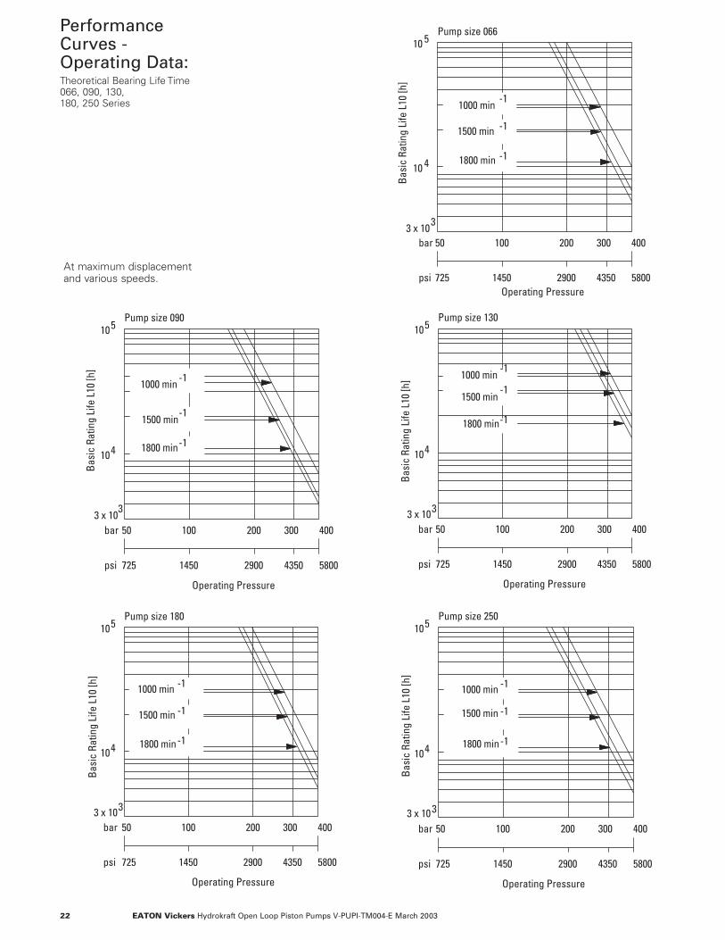
At maximum displacementand various speeds.
PerformanceCurves -Operating Data:Theoretical Bearing Life Time 066, 090, 130,180, 250 Series
23EATON Vickers Hydrokraft Open Loop Piston Pumps V-PUPI-TM004-E March 2003
psi
bar0
Operating Pressure
100 200 300
0 1000 2000 3000 4000 5000
11
10
98
7
6
5
4
32
1
0
3.0
2.5
2.0
1.5
1.0
0.5
0
USgpm L/min
Drai
n Fl
ow
PFX/PVX066/090
3
2
1
psi
bar0
Operating Pressure
100 200 300
0 1000 2000 3000 4000 5000
11
10
9
8
7
6
5
4
3
2
10
3.0
2.5
2.0
1.5
1.0
0.5
0
USgpm L/min PFX/PVX180
3
2
1
12
13
14
15
16
3.5
4.0
psi
bar0
Operating Pressure
100 200 300
0 1000 2000 3000 4000 5000
11
10
9
8
7
6
5
4
3
2
10
3.0
2.5
2.0
1.5
1.0
0.5
0
USgpm L/min
PFX/PVX130
3
2
1
12
13
143.5
4.0
psi
bar0
Operating Pressure
100 200 300
0 1000 2000 3000 4000 5000
11
10
9
8
7
6
54
3
2
1
0
3.0
2.5
2.0
1.5
1.0
0.5
0
USgpm L/min
PFX/PVX250
3
2
1
12
13
143.5
4.0
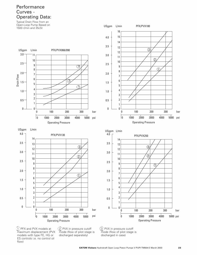
1 PFX and PVX models atmaximum displacement (PVXmodels with type FE, HG orES controls i.e. no control oilflow)
2 PVX in pressure cutoffmode (flow of pilot stage isdischarged separately)
3 PVX in pressure cutoffmode (flow of pilot stage isdischarged in case)
PerformanceCurves -Operating Data:Typical Drain Flow from anOpen-Loop Pump Based on1500 r/min and 35cSt
24 EATON Vickers Hydrokraft Open Loop Piston Pumps V-PUPI-TM004-E March 2003
Controls -DF, LR PressureCompensator/Power Control“X” Series - Open loop pump
WVC
S
p
H
0 100 200 300 400 bar
psi
Resp
onse
Tim
e (m
s)(V
null
to V
max
) 100
0
50
2000 4000 6000
250
130/180
066/090
Operating Pressure
p2
y
Up Down
Tu= time lagT = compensating timeg
t
uT
gTTguT
0,9 y max.
Swashplateyoke angle
pressureOutlet
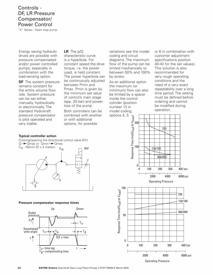
Energy saving hydraulicdrives are possible withpressure compensatedand/or power controlledpumps, especially incombination with theload-sensing option.DF The system pressureremains constant for the entire volume flowrate. System pressurecan be set eithermanually, hydraulically or electronically. Thestandard Hydrokraftpressure compensator is pilot operated andvery stable.
LR The p/Qcharacteristic curve is a hyperbola. Forconstant speed the drivetorque, i.e. the powerused, is held constant.The power hyperbola canbe continuously adjustedbetween Pmin andPmax. Pmin is given bythe minimum set valueof control’s main stage(app. 20 bar) and powerloss of the pump.Both controllers can becombined with anotheror with additionaloptions, for possible
variations see the modelcoding and circuitdiagrams. The maximumflow of the pump can belimited mechanically tobetween 50% and 100%by screw. As an additional optionthe maximum (orminimum) flow can alsobe limited by a spacerinside the controlcylinder (positionnumber 13 in model coding, options 4, 5
or 6 in combination withcustomer adjustmentspecifications position40-43 for the set values).This solution is alsorecommended for very rough operatingconditions and the need of a very exactrepeatability over a longtime period. The settingmust be defined beforeordering and cannot be modified duringoperation.
Typical controller action
(Closing/opening the directional control valve WV)Q Qmax or Qmin QmaxCH - 50mm ID x 2 meters
Pressure compensator response times
0 100 200 300 400 bar
psi
Resp
onse
Tim
e (m
s)(V
null
to V
max
)
200
0
2000 4000 6000
100
Operating Pressure
250
130/180
066/090
25EATON Vickers Hydrokraft Open Loop Piston Pumps V-PUPI-TM004-E March 2003
Controls -DF, LR PressureCompensator/Power Control“X” Series - Open loop pump
BA
Mechanicaladjustment
Minimum pressureapproximately 20 bar (280 psi)
adjustmentElectrical
..DF000A00..
Qmax
Alternatively
..DF000A0K..
Remote portonlyX1
..DF000A0F..
Q+
p
Electrical
..LR000A20.. ..LR000A2K... ..LR000A2F...
A B
Mechanicaladjustment adjustmentX1
Qmax
Remote portonly
Alternatively
Q+
p
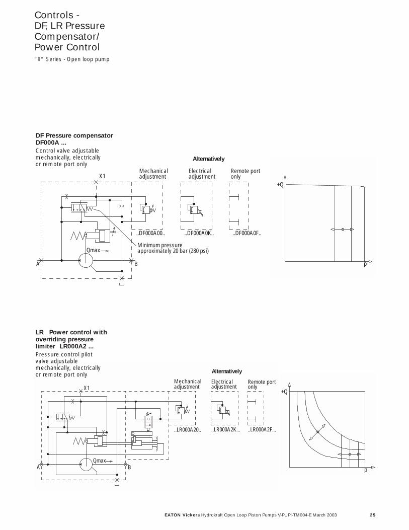
DF Pressure compensatorDF000A ...
Control valve adjustablemechanically, electrically or remote port only
LR Power control withoverriding pressure limiter LR000A2 ...
Pressure control pilot valve adjustablemechanically, electrically or remote port only
26 EATON Vickers Hydrokraft Open Loop Piston Pumps V-PUPI-TM004-E March 2003
Controls -DF, LR PressureCompensator/Power Control“X” Series - Open loop pump
A B
XMechanicaladjustment adjustment
Electrical2
X1
Qmax
..DF000A10.. ..DF000A1K..
Remote portonly
Alternatively
..DF000A1F..
Q+
p
A B
XMechanicaladjustment adjustment
Electrical
X2
1 Alternatively
Qmax
..LR000A30.. ..LR000A3K..
Remote portonly
..LR000A3F..
Q+
p
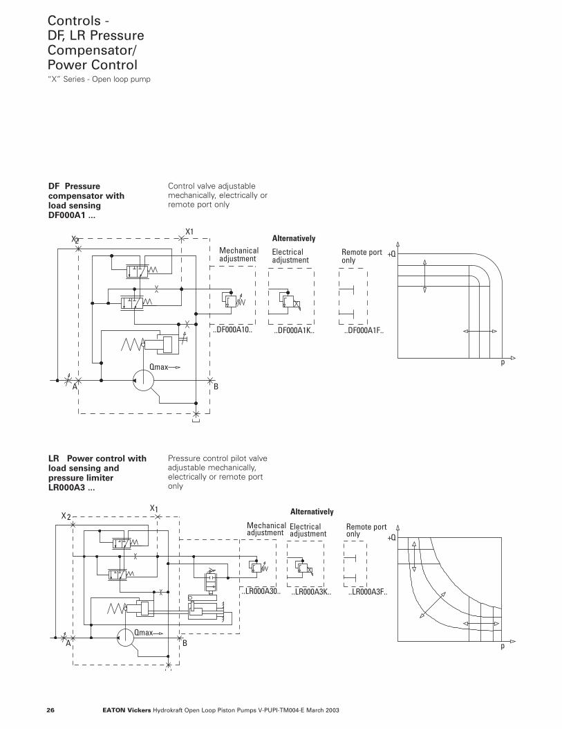
DF Pressure compensator with load sensingDF000A1 ...
Control valve adjustablemechanically, electrically orremote port only
LR Power control withload sensing and pressure limiterLR000A3 ...
Pressure control pilot valveadjustable mechanically,electrically or remote portonly
27EATON Vickers Hydrokraft Open Loop Piston Pumps V-PUPI-TM004-E March 2003
Controls -DQ MooringControl“X” Series - Open loop pump
BA
Mechanicaladjustment
Minimum pressureapproximately 20 bar (280psi)
adjustmentElectrical
..DQ000A00..
Qmax
Alternatively
..DQ000A0K..
Remote portonlyX1
..DQ000A0F..
Q+
p
-Q
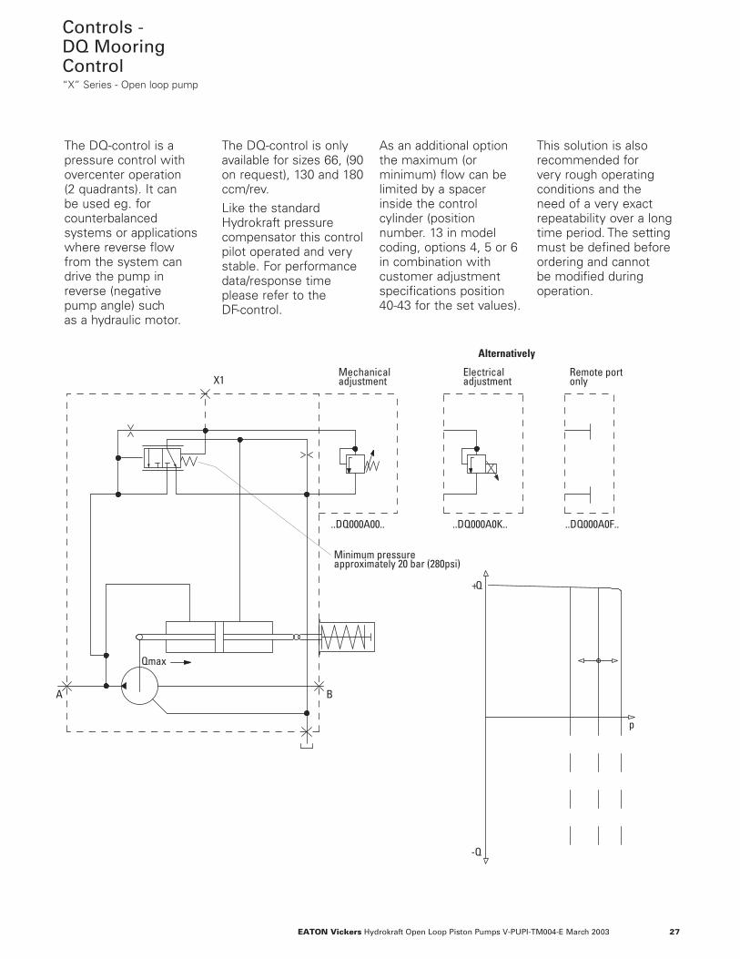
The DQ-control is apressure control withovercenter operation (2 quadrants). It can be used eg. forcounterbalancedsystems or applicationswhere reverse flow from the system candrive the pump inreverse (negative pump angle) such as a hydraulic motor.
The DQ-control is onlyavailable for sizes 66, (90on request), 130 and 180ccm/rev.Like the standardHydrokraft pressurecompensator this controlpilot operated and verystable. For performancedata/response timeplease refer to the DF-control.
As an additional optionthe maximum (orminimum) flow can belimited by a spacerinside the controlcylinder (positionnumber. 13 in modelcoding, options 4, 5 or 6in combination withcustomer adjustmentspecifications position 40-43 for the set values).
This solution is alsorecommended for very rough operatingconditions and the need of a very exactrepeatability over a longtime period. The settingmust be defined beforeordering and cannot be modified duringoperation.
28 EATON Vickers Hydrokraft Open Loop Piston Pumps V-PUPI-TM004-E March 2003
Controls -HG Manual Adjustment Displacement Control FE“X” Series - Open loop pump
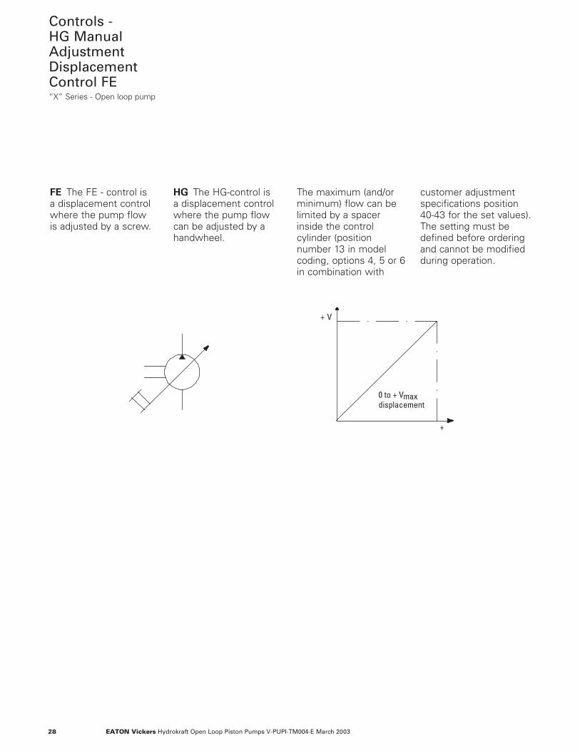
FE The FE - control is a displacement controlwhere the pump flow is adjusted by a screw.
HG The HG-control is a displacement controlwhere the pump flowcan be adjusted by ahandwheel.
The maximum (and/orminimum) flow can belimited by a spacerinside the controlcylinder (positionnumber 13 in modelcoding, options 4, 5 or 6in combination with
customer adjustmentspecifications position40-43 for the set values).The setting must bedefined before orderingand cannot be modifiedduring operation.
V+
+
0 to + Vmaxdisplacement
29EATON Vickers Hydrokraft Open Loop Piston Pumps V-PUPI-TM004-E March 2003
Controls -Electric MotorDisplacementControl ES“X” Series - Open loop pump
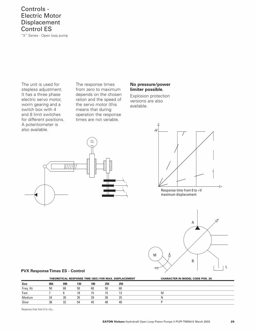
THEORETICAL RESPONSE TIME (SEC) FOR MAX. DISPLACEMENT CHARACTER IN MODEL CODE POS. 26
Size 066 090 130 180 250 250Freq. Hz 50 60 50 60 50 60Fast 7 6 18 15 15 13 MMedium 24 20 35 29 30 25 NSlow 38 32 54 45 48 40 P
Response time from 0 to +Qmax
V+
Response time from 0 to +Vmaximum displacement
A
M
B
LPVX Response Times ES - Control
The unit is used forstepless adjustment. It has a three phaseelectric servo motor,worm gearing and aswitch box with 4 and 8 limit switches for different positions. A potentiometer is also available.
The response timesfrom zero to maximumdepends on the chosenration and the speed ofthe servo motor (thismeans that duringoperation the responsetimes are not variable.
No pressure/powerlimiter possible.
Explosion protectionversions are alsoavailable.
30 EATON Vickers Hydrokraft Open Loop Piston Pumps V-PUPI-TM004-E March 2003
Controls -Pressure SignalDisplacementControl DP“X” Series - Open loop pump
pSt
LBS
Qmax
A T P T A B
P T A B
P T A BP T
M8
D1
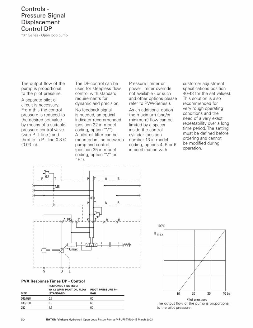
The output flow of thepump is proportional to the pilot pressureA separate pilot oilcircuit is necessary.From this the controlpressure is reduced tothe desired set value by means of a suitablepressure control valve(with P -T line ) andthrottle in P - line 0.8 Ø(0.03 in).
The DP-control can beused for steepless flowcontrol with standardrequirements fordynamic and precision.No feedback signal is needed, an opticalindicator recommended(position 22 in modelcoding, option “V”). A pilot oil filter can bemounted in line betweenpump and control (position 35 in modelcoding, option “V” or“E”).
Pressure limiter orpower limiter overridenot available ( or suchand other options pleaserefer to PVW-Series ).As an additional optionthe maximum (and/orminimum) flow can belimited by a spacerinside the controlcylinder (position number 13 in modelcoding, options 4, 5 or 6in combination with
customer adjustmentspecifications position 40-43 for the set values).This solution is alsorecommended for very rough operatingconditions and the need of a very exactrepeatability over a longtime period. The settingmust be defined beforeordering and cannot be modified duringoperation.
Pilot pressure
10 20 40 bar30
Q max
100%
RESPONSE TIME (SEC)W/ 12 L/MIN PILOT OIL FLOW PILOT PRESSURE PST
SIZE (STANDARD) BAR
066/090 0.7 60130/180 0.9 60250 1.1 60
PVX Response Times DP - Control
The output flow of the pump is proportionalto the pilot pressure
31EATON Vickers Hydrokraft Open Loop Piston Pumps V-PUPI-TM004-E March 2003
Controls -Proportional ValveDisplacementControl SP“X” Series - Open loop pump
St1p
StM
BA
P T
A B L1/L2
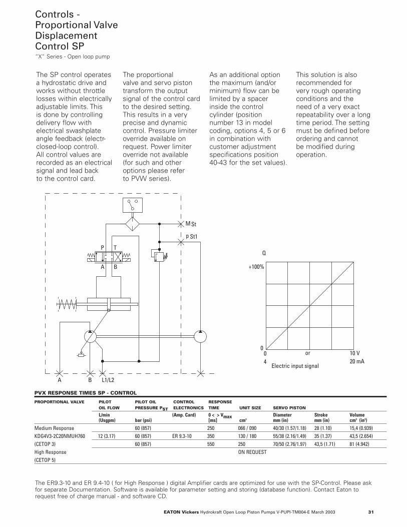
The SP control operatesa hydrostatic drive andworks without throttlelosses within electricallyadjustable limits. This is done by controllingdelivery flow withelectrical swashplateangle feedback (electr-closed-loop control).All control values arerecorded as an electricalsignal and lead back to the control card.
The proportional valve and servo pistontransform the outputsignal of the control cardto the desired setting.This results in a veryprecise and dynamiccontrol. Pressure limiteroverride available onrequest. Power limiteroverride not available (for such and otheroptions please refer to PVW series).
As an additional optionthe maximum (and/orminimum) flow can belimited by a spacerinside the controlcylinder (positionnumber 13 in modelcoding, options 4, 5 or 6in combination withcustomer adjustmentspecifications position 40-43 for the set values).
This solution is alsorecommended for very rough operatingconditions and the need of a very exactrepeatability over a longtime period. The settingmust be defined beforeordering and cannot be modified duringoperation.
Electric input signal
04
10 V20 mA
+100%
0
Q
or
PVX RESPONSE TIMES SP - CONTROL
PROPORTIONAL VALVE PILOT PILOT OIL CONTROL RESPONSEOIL FLOW PRESSURE PST ELECTRONICS TIME UNIT SIZE SERVO PISTON
L/min (Amp. Card) 0 < > Vmax Diameter Stroke Volume(Usgpm) bar (psi) [ms] cm3 mm (in) mm (in) cm3 (in3)
Medium Response 60 (857) 250 066 / 090 40/30 (1.57/1.18) 28 (1.10) 15,4 (0.939)KDG4V3-2C20NMUH760 12 (3.17) 60 (857) ER 9.3-10 350 130 / 180 55/38 (2.16/1.49) 35 (1.37) 43,5 (2.654) (CETOP 3) 60 (857) 550 250 70/50 (2.76/1.97) 43,5 (1.71) 81 (4.942) High Response ON REQUEST(CETOP 5)
The ER9.3-10 and ER 9.4-10 ( for High Response ) digital Amplifier cards are optimized for use with the SP-Control. Please askfor separate Documentation. Software is available for parameter setting and storing (database function). Contact Eaton torequest free of charge manual - and software CD.
32
58
Ø125 h8
80
160
120
(180)
Ø18
155
210175
15035
M14
154
218 56
68
15
(367)
8
16
58
68
+0.2
0 26 120
246
10 h9
Ø38 k6
41
rightMB
Center boreDM12 DIN332
MA
A
L5
L2
L1
B
L3
L2B
L5
4xM10-20deep
W40x1.25x10aDIN 5480
Center boreDM12 DIN332
cw
M12-20deep
69.8
35.7
27.8
Ø38
(25)
57.2
1", 6000psi
M12x25deep
Port A
Port B1 1/2", 3000psi
EATON Vickers Hydrokraft Open Loop Piston Pumps V-PUPI-TM004-E March 2003
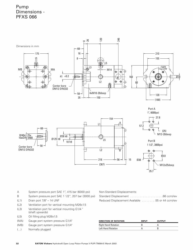
PumpDimensions -PFXS 066
Dimensions in mm
A System pressure port SAE 1’’, 415 bar (6000 psi)
B System pressure port SAE 1 1/2‘’, 207 bar (3000 psi)
(L1) Drain port 7/8" – 14 UNF
(L2) Ventilation port for vertical mounting M26x1.5
(L3) Ventilation port for vertical mounting G1/4 " (shaft upwards)
(L5) Oil filling plug M26x1.5
(MA) Gauge port system pressure G1/4"
(MB) Gauge port system pressure G1/4"
(…) Normally plugged
Non-Standard Displacements:
Standard Displacement . . . . . . . . . . . . . . . . . . . . .66 ccm/rev
Reduced Displacement Available . . . . . . . . .55 or 44 ccm/rev
DIRECTION OF ROTATION INPUT OUTPUT
Right Hand Rotation B ALeft Hand Rotation A B
33EATON Vickers Hydrokraft Open Loop Piston Pumps V-PUPI-TM004-E March 2003
M12-20deep
77.7
42.88
58
Ø125 h8
80
160
120
(180)
Ø18
155
210175
217.5
15035
(25)
27.8
57.2
M10
154
218 56
50
68
15
(367)
(372)
8
16
68
58
+0.2
Ø38 k6
10 h9
410 26 12
0
246
rightMB
Center boreDM12 DIN332
MA
A
L5
L2
L1
B
L3
L2B
L5
1", 6000psi
4xM10-20deep
M12x25deep
Port A
Port B
W40x1.25x10aDIN 5480
2", 3000psiCenter boreDM12 DIN332
cw
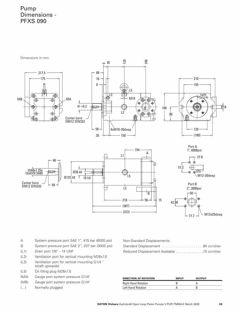
PumpDimensions -PFXS 090
Dimensions in mm
A System pressure port SAE 1’’, 415 bar (6000 psi)
B System pressure port SAE 2‘’, 207 bar (3000 psi)
(L1) Drain port 7/8" – 14 UNF
(L2) Ventilation port for vertical mounting M26x1.5
(L3) Ventilation port for vertical mounting G1/4 " (shaft upwards)
(L5) Oil filling plug M26x1.5
(MA) Gauge port system pressure G1/4"
(MB) Gauge port system pressure G1/4"
(…) Normally plugged
Non-Standard Displacements:
Standard Displacement . . . . . . . . . . . . . . . . . . . . .90 ccm/rev
Reduced Displacement Available . . . . . . . . . . . . . .75 ccm/rev
DIRECTION OF ROTATION INPUT OUTPUT
Right Hand Rotation B ALeft Hand Rotation A B
34 EATON Vickers Hydrokraft Open Loop Piston Pumps V-PUPI-TM004-E March 2003
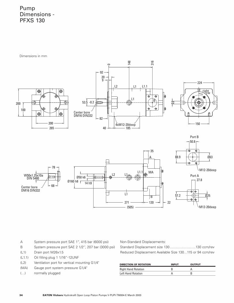
PumpDimensions -PFXS 130
Ø160 h8
224
40 185
271 120
22
W50x1.25x10aDIN 5480
209
78
200265
100
200
150
22(505)
Ø6388.9
50.8
57.2 Ø25
35
68
53.5
82
92
-0.2
27.814 h9
Ø50 k6
148
316
0
right
DM16 DIN332Center bore
4xM12-20deep
M12-20deep
M12-20deep
L1
L2 L1.1L1
L2
L1
L1.1 MA
A
B
Port B
Port A
B
L1
DM16 DIN332Center bore
cw
Dimensions in mm
A System pressure port SAE 1’’, 415 bar (6000 psi)
B System pressure port SAE 2 1/2‘’, 207 bar (3000 psi)
(L1) Drain port M26x1.5
(L1.1) Oil filling plug 1 1/16”-12UNF
(L2) Ventilation port for vertical mounting G1/4"
(MA) Gauge port system pressure G1/4"
(…) normally plugged
DIRECTION OF ROTATION INPUT OUTPUT
Right Hand Rotation B ALeft Hand Rotation A B
Non-Standard Displacements:
Standard Displacement size 130...........................130 ccm/rev
Reduced Displacement Available Size 130...115 or 94 ccm/rev
35EATON Vickers Hydrokraft Open Loop Piston Pumps V-PUPI-TM004-E March 2003
Ø160 h8
224
40 185
271 120
22
W50x1.25x10aDIN 5480
209
78
200265
100
200
150
2(505)
Ø6388.9
50.83
68
53.5
82
Ø50 k6
14 h9
92
-0.2
66.7Ø32
31.8
14816
316
right
DM16 DIN332Center bore
4xM12-20deep
M12-20deep
L1
L2 L1.1
L2
L1
L1.1 MA
A
B
Port B
Port A
B
L1
DM16 DIN332Center bore
A
M14-20deep
L1
cw
B
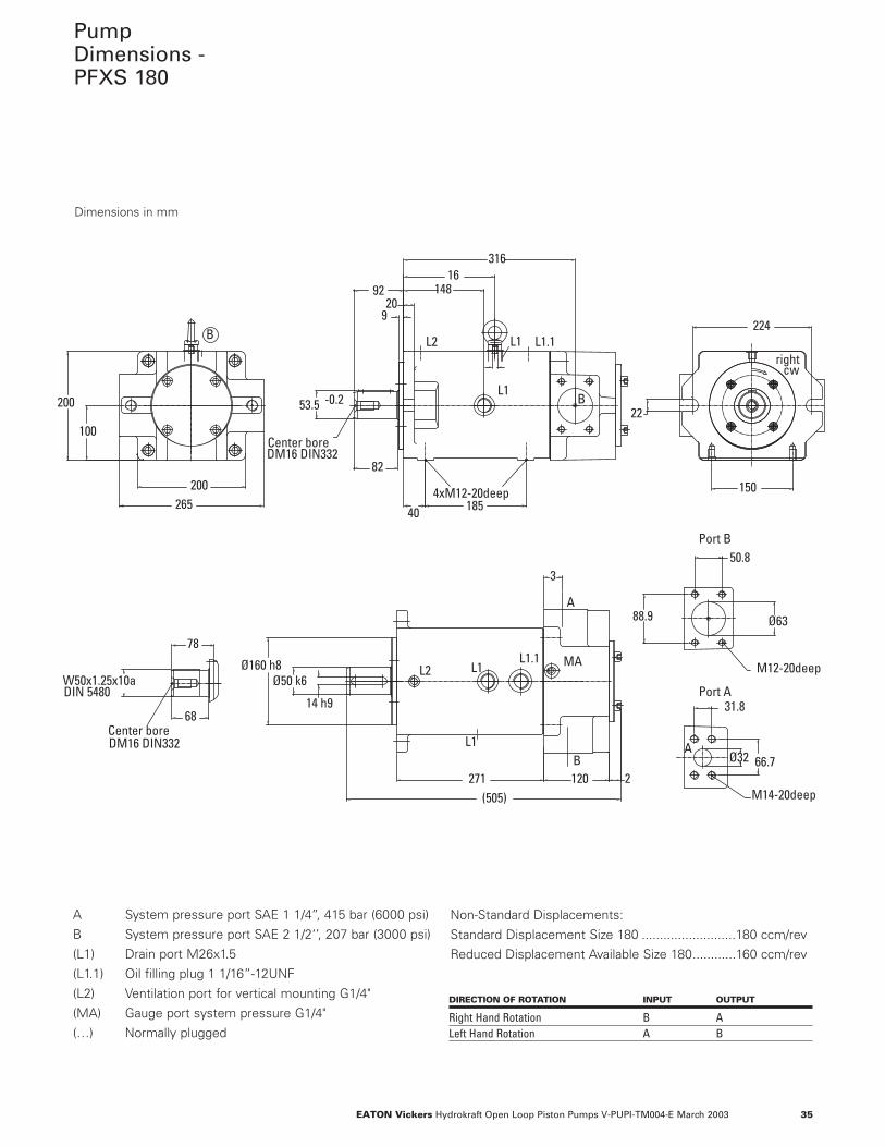
PumpDimensions -PFXS 180
Dimensions in mm
A System pressure port SAE 1 1/4’’, 415 bar (6000 psi)
B System pressure port SAE 2 1/2‘’, 207 bar (3000 psi)
(L1) Drain port M26x1.5
(L1.1) Oil filling plug 1 1/16”-12UNF
(L2) Ventilation port for vertical mounting G1/4"
(MA) Gauge port system pressure G1/4"
(…) Normally plugged
DIRECTION OF ROTATION INPUT OUTPUT
Right Hand Rotation B ALeft Hand Rotation A B
Non-Standard Displacements:
Standard Displacement Size 180 ..........................180 ccm/rev
Reduced Displacement Available Size 180............160 ccm/rev
36 EATON Vickers Hydrokraft Open Loop Piston Pumps V-PUPI-TM004-E March 2003
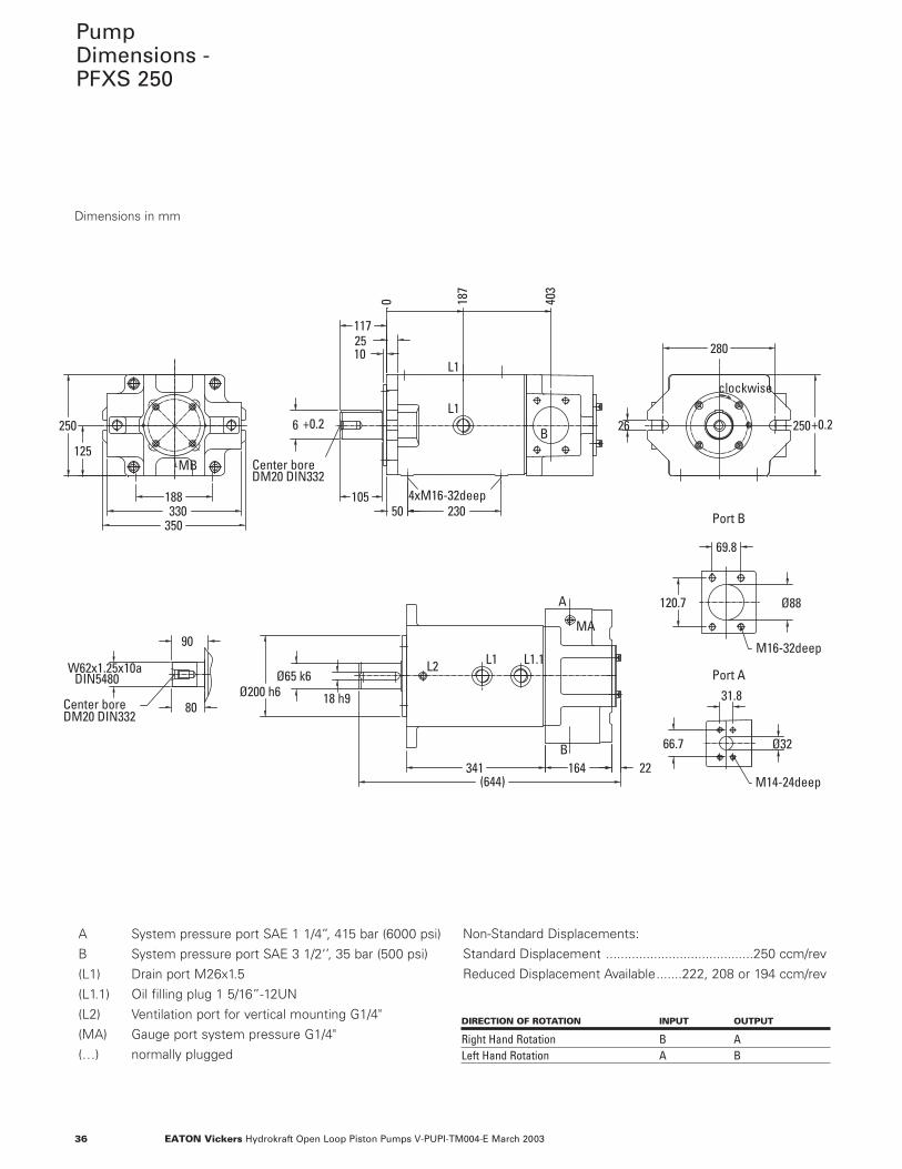
PumpDimensions -PFXS 250
26
22(644)
341 164
125
250
230188330
350
10550
Ø200 h6Ø65 k6
2510 280
250+0.2
Ø32
31.8
120.7
69.8
Ø88
66.7
DIN5480W62x1.25x10a
80
90
18 h9
6 +0.2
187
403
0
117
B
4xM16-32deep
L2 L1 L1.1
DM20 DIN332Center bore
L1
B
L1
MA
A
Port A
Port B
M16-32deep
M14-24deep
DM20 DIN332Center bore
MB
clockwise
Dimensions in mm
A System pressure port SAE 1 1/4’’, 415 bar (6000 psi)
B System pressure port SAE 3 1/2‘’, 35 bar (500 psi)
(L1) Drain port M26x1.5
(L1.1) Oil filling plug 1 5/16”-12UN
(L2) Ventilation port for vertical mounting G1/4"
(MA) Gauge port system pressure G1/4"
(…) normally plugged
DIRECTION OF ROTATION INPUT OUTPUT
Right Hand Rotation B ALeft Hand Rotation A B
Non-Standard Displacements:
Standard Displacement ........................................250 ccm/rev
Reduced Displacement Available.......222, 208 or 194 ccm/rev

37EATON Vickers Hydrokraft Open Loop Piston Pumps V-PUPI-TM004-E March 2003
38 EATON Vickers Hydrokraft Open Loop Piston Pumps V-PUPI-TM004-E March 2003
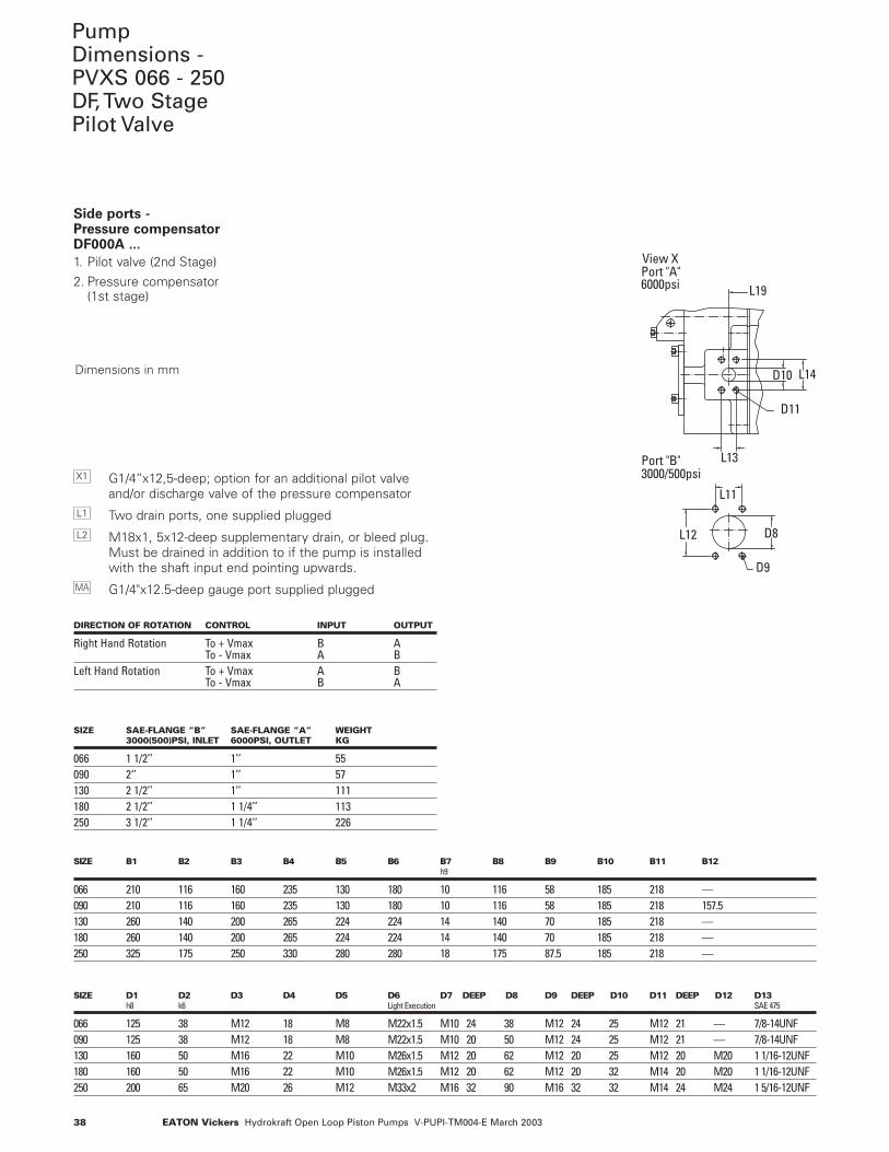
PumpDimensions - PVXS 066 - 250DF, Two StagePilot Valve
L12 D8
L14
L13
D10
L11
D9
D11
View X
3000/500psiPort "B"
Port "A"6000psi L19
Side ports - Pressure compensatorDF000A ...
1. Pilot valve (2nd Stage)
2. Pressure compensator (1st stage)
G1/4’’x12,5-deep; option for an additional pilot valveand/or discharge valve of the pressure compensator
Two drain ports, one supplied plugged
M18x1, 5x12-deep supplementary drain, or bleed plug.Must be drained in addition to if the pump is installedwith the shaft input end pointing upwards.
G1/4"x12.5-deep gauge port supplied pluggedMA
L2
L1
X1
DIRECTION OF ROTATION CONTROL INPUT OUTPUT
Right Hand Rotation To + Vmax B ATo - Vmax A B
Left Hand Rotation To + Vmax A BTo - Vmax B A
SIZE SAE-FLANGE “B” SAE-FLANGE “A” WEIGHT3000(500)PSI, INLET 6000PSI, OUTLET KG
066 1 1/2’’ 1’’ 55090 2‘’ 1’’ 57130 2 1/2’’ 1’’ 111180 2 1/2’’ 1 1/4’’ 113250 3 1/2’’ 1 1/4’’ 226
SIZE B1 B2 B3 B4 B5 B6 B7 B8 B9 B10 B11 B12h9
066 210 116 160 235 130 180 10 116 58 185 218 —090 210 116 160 235 130 180 10 116 58 185 218 157.5130 260 140 200 265 224 224 14 140 70 185 218 —180 260 140 200 265 224 224 14 140 70 185 218 —250 325 175 250 330 280 280 18 175 87.5 185 218 —
SIZE D1 D2 D3 D4 D5 D6 D7 DEEP D8 D9 DEEP D10 D11 DEEP D12 D13h8 k6 Light Execution SAE 475
066 125 38 M12 18 M8 M22x1.5 M10 24 38 M12 24 25 M12 21 — 7/8-14UNF090 125 38 M12 18 M8 M22x1.5 M10 20 50 M12 24 25 M12 21 — 7/8-14UNF130 160 50 M16 22 M10 M26x1.5 M12 20 62 M12 20 25 M12 20 M20 1 1/16-12UNF180 160 50 M16 22 M10 M26x1.5 M12 20 62 M12 20 32 M14 20 M20 1 1/16-12UNF250 200 65 M20 26 M12 M33x2 M16 32 90 M16 32 32 M14 24 M24 1 5/16-12UNF
Dimensions in mm
39EATON Vickers Hydrokraft Open Loop Piston Pumps V-PUPI-TM004-E March 2003
B6B3
H2
H9
H8H7
H3
B10B11
H6
B4
B7 h9
B2
B5
B1
D12
H1
B9B8
12
H4+0.2
24
cw
MA
X1L1L1
L1 L1
B12
H5
L2
L9
L3
L1
L6
L4
L8L5
L7
D3
D6
L15
L16
L17
D5
L10
L18
L20
Center boreDM16 DIN332
+Vmax0
orificeinsideof the control valve
X1
M18x1.5-12deep
Size 090L1
L2
B
D1 h8D4D2 k6
MA
Size 090
X
A
B
L1
L1
D13
L3
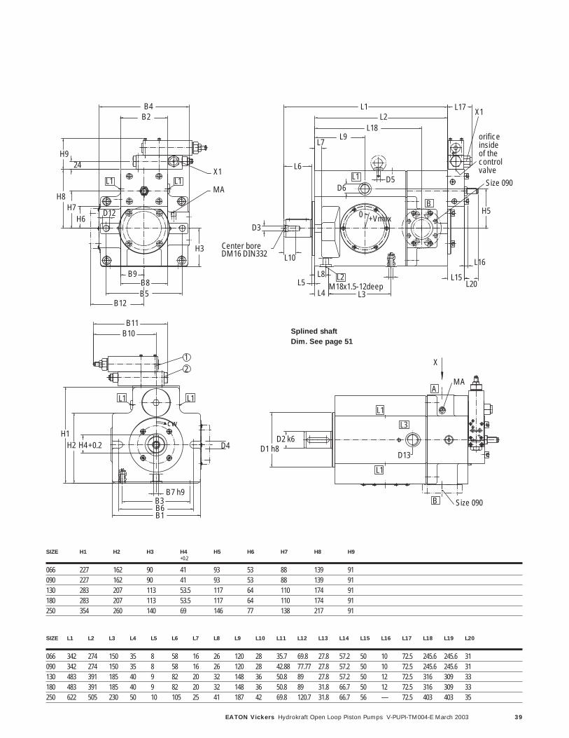
SIZE H1 H2 H3 H4 H5 H6 H7 H8 H9+0.2
066 227 162 90 41 93 53 88 139 91090 227 162 90 41 93 53 88 139 91130 283 207 113 53.5 117 64 110 174 91180 283 207 113 53.5 117 64 110 174 91250 354 260 140 69 146 77 138 217 91
SIZE L1 L2 L3 L4 L5 L6 L7 L8 L9 L10 L11 L12 L13 L14 L15 L16 L17 L18 L19 L20
066 342 274 150 35 8 58 16 26 120 28 35.7 69.8 27.8 57.2 50 10 72.5 245.6 245.6 31090 342 274 150 35 8 58 16 26 120 28 42.88 77.77 27.8 57.2 50 10 72.5 245.6 245.6 31130 483 391 185 40 9 82 20 32 148 36 50.8 89 27.8 57.2 50 12 72.5 316 309 33180 483 391 185 40 9 82 20 32 148 36 50.8 89 31.8 66.7 50 12 72.5 316 309 33250 622 505 230 50 10 105 25 41 187 42 69.8 120.7 31.8 66.7 56 — 72.5 403 403 35
Splined shaft
Dim. See page 51
40 EATON Vickers Hydrokraft Open Loop Piston Pumps V-PUPI-TM004-E March 2003
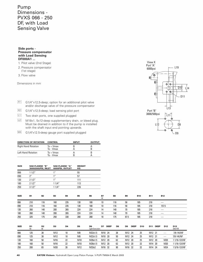
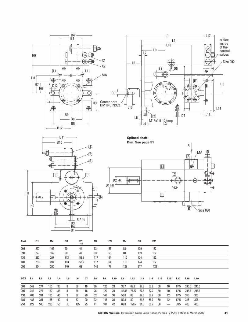
PumpDimensions - PVXS 066 - 250DF, with LoadSensing Valve
D8
L14D10
L12
L11
L13
D9
D11
View X
Port "B"3000/500psi
6000psiPort "A"
L19
Side ports - Pressure compensatorwith Load SensingDF000A1 ...
1. Pilot valve (2nd Stage)
2. Pressure compensator (1st stage)
3. Flow valve
G1/4’’x12,5-deep; option for an additional pilot valveand/or discharge valve of the pressure compensator
G1/4’’x12,5-deep; load sensing pilot port
Two drain ports, one supplied plugged
M18x1, 5x12-deep supplementary drain, or bleed plug.Must be drained in addition to if the pump is installedwith the shaft input end pointing upwards.
G1/4"x12.5-deep gauge port supplied pluggedMA
L2
L1
X2
X1
DIRECTION OF ROTATION CONTROL INPUT OUTPUT
Right Hand Rotation To + Vmax B ATo - Vmax A B
Left Hand Rotation To + Vmax A BTo - Vmax B A
SIZE SAE-FLANGE “B” SAE-FLANGE “A” WEIGHT3000(500)PSI, INLET 6000PSI, OUTLET KG
066 1 1/2’’ 1’’ 55090 2‘’ 1’’ 57130 2 1/2’’ 1’’ 111180 2 1/2’’ 1 1/4’’ 113250 3 1/2’’ 1 1/4’’ 226
SIZE B1 B2 B3 B4 B5 B6 B7 B8 B9 B10 B11 B12h9
066 210 116 160 235 130 180 10 116 58 185 218 —090 210 116 160 235 130 180 10 116 58 185 218 157.5130 260 140 200 265 224 224 14 140 70 185 218 —180 260 140 200 265 224 224 14 140 70 185 218 —250 325 175 250 330 280 280 18 175 87.5 185 218 —
SIZE D1 D2 D3 D4 D5 D6 D7 DEEP D8 D9 DEEP D10 D11 DEEP D12 D13h8 k6 Light Execution SAE 475
066 125 38 M12 18 M8 M22x1.5 M10 24 38 M12 24 25 M12 21 — 7/8-14UNF090 125 38 M12 18 M8 M22x1.5 M10 20 50 M12 24 25 M12 21 — 7/8-14UNF130 160 50 M16 22 M10 M26x1.5 M12 20 62 M12 20 25 M12 20 M20 1 1/16-12UNF180 160 50 M16 22 M10 M26x1.5 M12 20 62 M12 20 32 M14 20 M20 1 1/16-12UNF250 200 65 M20 26 M12 M33x2 M16 32 90 M16 32 32 M14 24 M24 1 5/16-12UNF
Dimensions in mm
41EATON Vickers Hydrokraft Open Loop Piston Pumps V-PUPI-TM004-E March 2003
L5
L7L9
L4
L8
L2L1
L18
H3
B9B8B5
D2 k6D1 h8
B4
H8
H7H6
D12
H9
B2
L6
D3
L10
H2
L16
L15
H1
B6B1
L3
D7
B3B7 h9
B10B11
L17
H5
D6D5
D4H4+0.2
1
3
2
Center boreDM16 DIN332
MA
X2X1
Size 090
MA
M18x1.5-12deep
+Vmax0
Size 090
cw
orifice insideof the control valves
X
B12
L1 L1
B
L1
L1
L2
A
B
L1
L1 L1
D13
L3
SIZE H1 H2 H3 H4 H5 H6 H7 H8 H9+0.2
066 227 162 90 41 93 53 88 139 132090 227 162 90 41 93 53 88 139 132130 283 207 113 53.5 117 64 110 174 132180 283 207 113 53.5 117 64 110 174 132 250 354 260 140 69 146 77 138 217 132
SIZE L1 L2 L3 L4 L5 L6 L7 L8 L9 L10 L11 L12 L13 L14 L15 L16 L17 L18 L19
066 342 274 150 35 8 58 16 26 120 28 35.7 69.8 27.8 57.2 50 10 67.5 245.6 245.6090 342 274 150 35 8 58 16 26 120 28 42.88 77.77 27.8 57.2 50 10 67.5 245.6 245.6130 483 391 185 40 9 82 20 32 148 36 50.8 89 27.8 57.2 50 12 67.5 316 306180 483 391 185 40 9 82 20 32 148 36 50.8 89 31.8 66.7 50 12 67.5 316 306 250 622 505 230 50 10 105 25 41 187 42 69.8 120.7 31.8 66.7 56 — 70.5 403 403
Splined shaft
Dim. See page 51
42 EATON Vickers Hydrokraft Open Loop Piston Pumps V-PUPI-TM004-E March 2003
L14
L13
D10
D1
D2D11
View XPort "A"6000psi L19
B6B3
H2 D4
B10B11
H4
B7 h9
+0.2
B1
H1cw
1
2
L1 L1
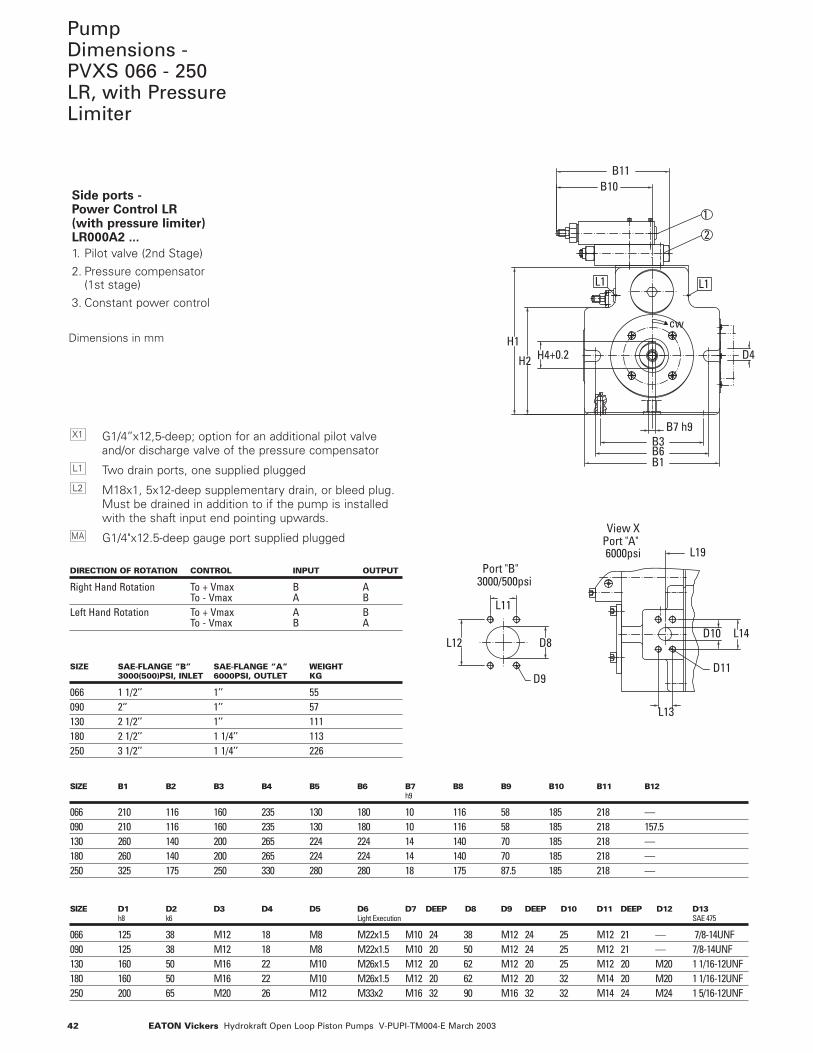
Side ports - Power Control LR (with pressure limiter)LR000A2 ...
1. Pilot valve (2nd Stage)
2. Pressure compensator (1st stage)
3. Constant power control
G1/4’’x12,5-deep; option for an additional pilot valveand/or discharge valve of the pressure compensator
Two drain ports, one supplied plugged
M18x1, 5x12-deep supplementary drain, or bleed plug.Must be drained in addition to if the pump is installedwith the shaft input end pointing upwards.
G1/4"x12.5-deep gauge port supplied pluggedMA
L2
L1
X1
DIRECTION OF ROTATION CONTROL INPUT OUTPUT
Right Hand Rotation To + Vmax B ATo - Vmax A B
Left Hand Rotation To + Vmax A BTo - Vmax B A
SIZE SAE-FLANGE “B” SAE-FLANGE “A” WEIGHT3000(500)PSI, INLET 6000PSI, OUTLET KG
066 1 1/2’’ 1’’ 55090 2‘’ 1’’ 57130 2 1/2’’ 1’’ 111180 2 1/2’’ 1 1/4’’ 113250 3 1/2’’ 1 1/4’’ 226
SIZE B1 B2 B3 B4 B5 B6 B7 B8 B9 B10 B11 B12h9
066 210 116 160 235 130 180 10 116 58 185 218 —090 210 116 160 235 130 180 10 116 58 185 218 157.5130 260 140 200 265 224 224 14 140 70 185 218 —180 260 140 200 265 224 224 14 140 70 185 218 —250 325 175 250 330 280 280 18 175 87.5 185 218 —
SIZE D1 D2 D3 D4 D5 D6 D7 DEEP D8 D9 DEEP D10 D11 DEEP D12 D13h8 k6 Light Execution SAE 475
066 125 38 M12 18 M8 M22x1.5 M10 24 38 M12 24 25 M12 21 — 7/8-14UNF090 125 38 M12 18 M8 M22x1.5 M10 20 50 M12 24 25 M12 21 — 7/8-14UNF130 160 50 M16 22 M10 M26x1.5 M12 20 62 M12 20 25 M12 20 M20 1 1/16-12UNF180 160 50 M16 22 M10 M26x1.5 M12 20 62 M12 20 32 M14 20 M20 1 1/16-12UNF250 200 65 M20 26 M12 M33x2 M16 32 90 M16 32 32 M14 24 M24 1 5/16-12UNF
Dimensions in mm
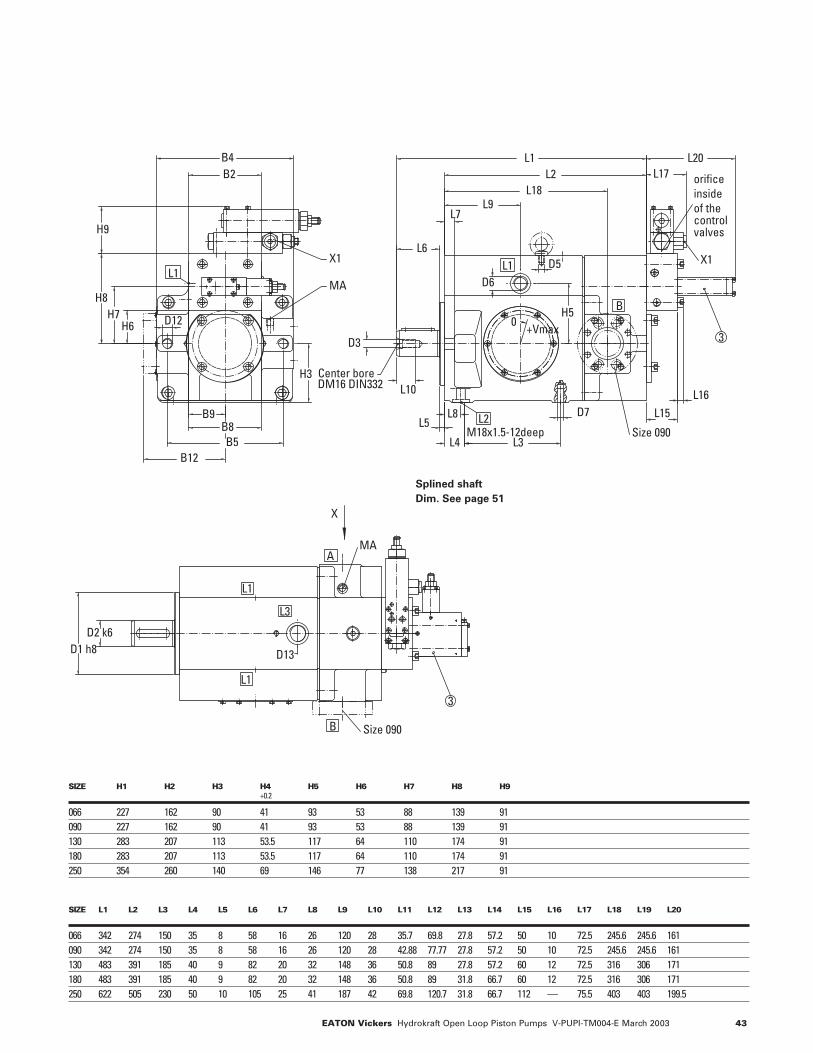
PumpDimensions - PVXS 066 - 250LR, with PressureLimiter
L12 D8
L11
D92
3000/500psiPort "B"
43EATON Vickers Hydrokraft Open Loop Piston Pumps V-PUPI-TM004-E March 2003
H5
L2
L9
L3
L1
H9
H8
L6
H7
H3
L4
L8L5
L7
D3H6
B4
D7
D6
L15L16
L17
D5
L10
B2
B5
D12
L18
B9B8
L20
Center boreDM16 DIN332
+Vmax0
X1
M18x1.5-12deep Size 090
MA
X1
orifice insideof the control valves
3
L1L1
L2
B
B12
D1 h8D2 k6
MA
Size 090
3
X
A
B
L1
L1
D13
L3
SIZE H1 H2 H3 H4 H5 H6 H7 H8 H9+0.2
066 227 162 90 41 93 53 88 139 91090 227 162 90 41 93 53 88 139 91130 283 207 113 53.5 117 64 110 174 91 180 283 207 113 53.5 117 64 110 174 91 250 354 260 140 69 146 77 138 217 91
SIZE L1 L2 L3 L4 L5 L6 L7 L8 L9 L10 L11 L12 L13 L14 L15 L16 L17 L18 L19 L20
066 342 274 150 35 8 58 16 26 120 28 35.7 69.8 27.8 57.2 50 10 72.5 245.6 245.6 161 090 342 274 150 35 8 58 16 26 120 28 42.88 77.77 27.8 57.2 50 10 72.5 245.6 245.6 161 130 483 391 185 40 9 82 20 32 148 36 50.8 89 27.8 57.2 60 12 72.5 316 306 171 180 483 391 185 40 9 82 20 32 148 36 50.8 89 31.8 66.7 60 12 72.5 316 306 171 250 622 505 230 50 10 105 25 41 187 42 69.8 120.7 31.8 66.7 112 — 75.5 403 403 199.5
Splined shaft
Dim. See page 51
44 EATON Vickers Hydrokraft Open Loop Piston Pumps V-PUPI-TM004-E March 2003
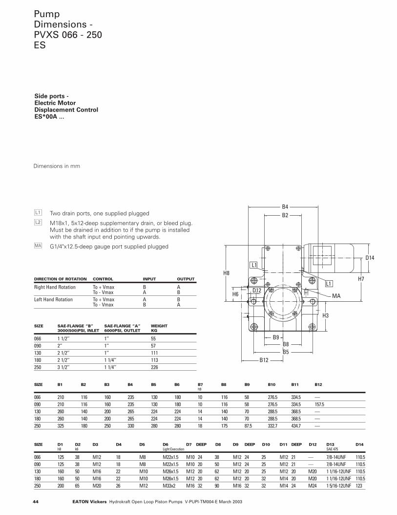
PumpDimensions - PVXS 066 - 250ES
H3
B9B8B5
D3
B4
H8
D12H6
H7
B2
D14
DM16 DIN332Center bore
MA
B12
L1
L1
Side ports - Electric MotorDisplacement ControlES*00A ...
Two drain ports, one supplied plugged
M18x1, 5x12-deep supplementary drain, or bleed plug.Must be drained in addition to if the pump is installedwith the shaft input end pointing upwards.
G1/4"x12.5-deep gauge port supplied pluggedMA
L2
L1
DIRECTION OF ROTATION CONTROL INPUT OUTPUT
Right Hand Rotation To + Vmax B ATo - Vmax A B
Left Hand Rotation To + Vmax A BTo - Vmax B A
SIZE SAE-FLANGE “B” SAE-FLANGE “A” WEIGHT3000(500)PSI, INLET 6000PSI, OUTLET KG
066 1 1/2’’ 1’’ 55090 2‘’ 1’’ 57130 2 1/2’’ 1’’ 111180 2 1/2’’ 1 1/4’’ 113250 3 1/2’’ 1 1/4’’ 226
SIZE B1 B2 B3 B4 B5 B6 B7 B8 B9 B10 B11 B12h9
066 210 116 160 235 130 180 10 116 58 276.5 334.5 —090 210 116 160 235 130 180 10 116 58 276.5 334.5 157.5130 260 140 200 265 224 224 14 140 70 288.5 368.5 —180 260 140 200 265 224 224 14 140 70 288.5 368.5 —250 325 180 250 330 280 280 18 175 87.5 332.7 434.7 —
SIZE D1 D2 D3 D4 D5 D6 D7 DEEP D8 D9 DEEP D10 D11 DEEP D12 D13 D14h8 k6 Light Execution SAE 475
066 125 38 M12 18 M8 M22x1.5 M10 24 38 M12 24 25 M12 21 — 7/8-14UNF 110.5 090 125 38 M12 18 M8 M22x1.5 M10 20 50 M12 24 25 M12 21 — 7/8-14UNF 110.5130 160 50 M16 22 M10 M26x1.5 M12 20 62 M12 20 25 M12 20 M20 1 1/16-12UNF 110.5180 160 50 M16 22 M10 M26x1.5 M12 20 62 M12 20 32 M14 20 M20 1 1/16-12UNF 110.5250 200 65 M20 26 M12 M33x2 M16 32 90 M16 32 32 M14 24 M24 1 5/16-12UNF 123
Dimensions in mm
45EATON Vickers Hydrokraft Open Loop Piston Pumps V-PUPI-TM004-E March 2003
L12 D8
D L
L13L11
D9
D11
View X
L18
Port "B"3000/500psi
6000psiPort "A"
L16
L5 D7
L3L4
L8
L10
D3
H7
D14
H5
L17
L1L2
L6
L7L9
D6
D5
L15
M18x1.5-12deepSize 090
DM16 DIN332Center bore
+Vmax0
A
L2
L1
B
D2 k6D1 h8
Size 090
MA
X
B
L1
L1
A
D13
L3
B6B1
B7 h9
H2
H1
B3
B11B10
D4
H4+0.2
cwL1
L1
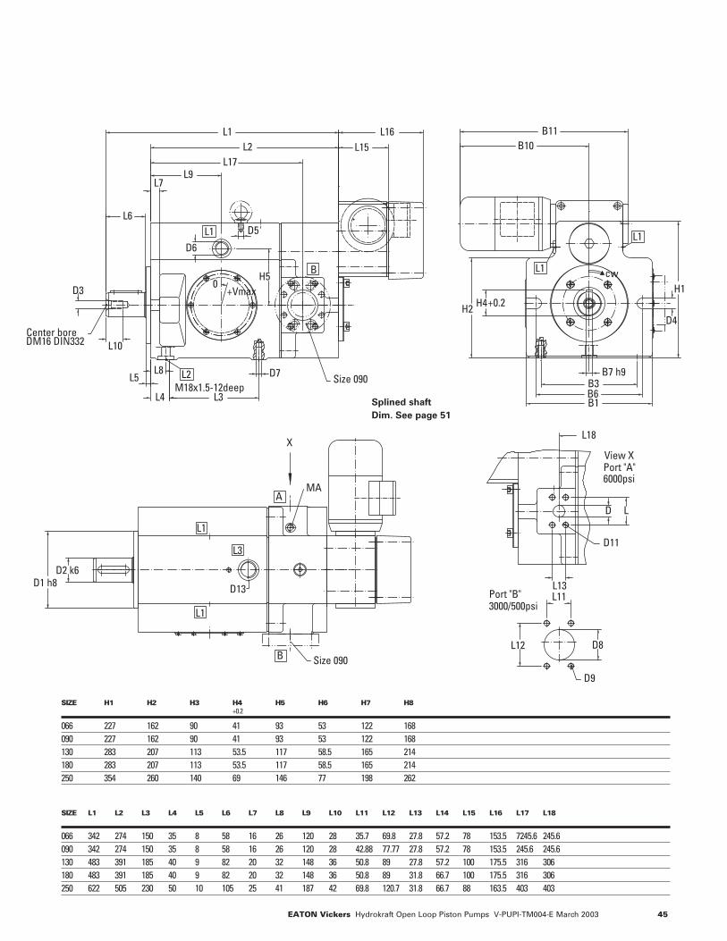
SIZE H1 H2 H3 H4 H5 H6 H7 H8+0.2
066 227 162 90 41 93 53 122 168090 227 162 90 41 93 53 122 168130 283 207 113 53.5 117 58.5 165 214180 283 207 113 53.5 117 58.5 165 214250 354 260 140 69 146 77 198 262
SIZE L1 L2 L3 L4 L5 L6 L7 L8 L9 L10 L11 L12 L13 L14 L15 L16 L17 L18
066 342 274 150 35 8 58 16 26 120 28 35.7 69.8 27.8 57.2 78 153.5 7245.6 245.6090 342 274 150 35 8 58 16 26 120 28 42.88 77.77 27.8 57.2 78 153.5 245.6 245.6130 483 391 185 40 9 82 20 32 148 36 50.8 89 27.8 57.2 100 175.5 316 306180 483 391 185 40 9 82 20 32 148 36 50.8 89 31.8 66.7 100 175.5 316 306 250 622 505 230 50 10 105 25 41 187 42 69.8 120.7 31.8 66.7 88 163.5 403 403
Splined shaft
Dim. See page 51
46 EATON Vickers Hydrokraft Open Loop Piston Pumps V-PUPI-TM004-E March 2003
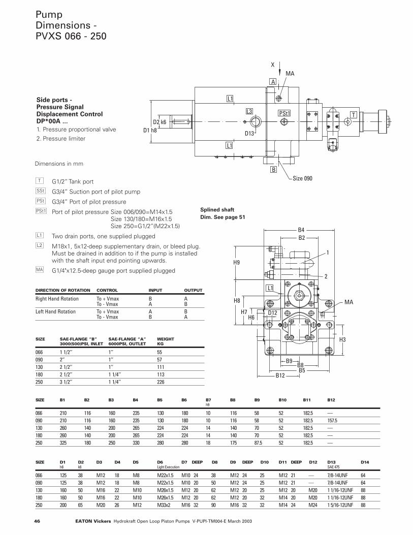
PumpDimensions - PVXS 066 - 250
Side ports - Pressure Signal Displacement ControlDP*00A ...
1. Pressure proportional valve
2. Pressure limiter
G1/2’’ Tank port
G3/4’’ Suction port of pilot pump
G3/4’’ Port of pilot pressure
Port of pilot pressure Size 006/090=M14x1.5Size 130/180=M16x1.5Size 250=G1/2’’(M22x1.5)
Two drain ports, one supplied plugged
M18x1, 5x12-deep supplementary drain, or bleed plug.Must be drained in addition to if the pump is installedwith the shaft input end pointing upwards.
G1/4"x12.5-deep gauge port supplied pluggedMA
L2
L1
PSt1
PSt
SSt
T
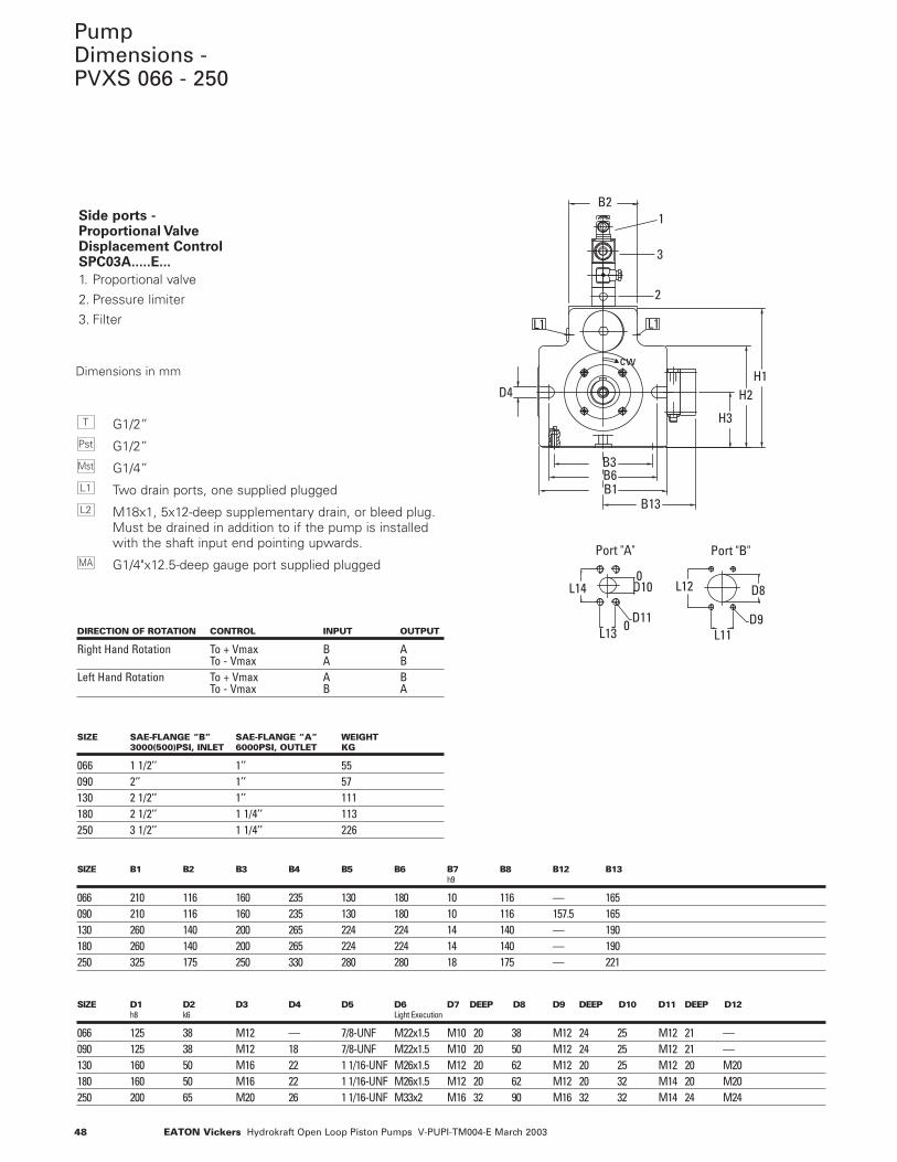
DIRECTION OF ROTATION CONTROL INPUT OUTPUT
Right Hand Rotation To + Vmax B ATo - Vmax A B
Left Hand Rotation To + Vmax A BTo - Vmax B A
SIZE SAE-FLANGE “B” SAE-FLANGE “A” WEIGHT3000(500)PSI, INLET 6000PSI, OUTLET KG
066 1 1/2’’ 1’’ 55090 2‘’ 1’’ 57130 2 1/2’’ 1’’ 111180 2 1/2’’ 1 1/4’’ 113250 3 1/2’’ 1 1/4’’ 226
SIZE B1 B2 B3 B4 B5 B6 B7 B8 B9 B10 B11 B12h9
066 210 116 160 235 130 180 10 116 58 52 182.5 —090 210 116 160 235 130 180 10 116 58 52 182.5 157.5130 260 140 200 265 224 224 14 140 70 52 182.5 —180 260 140 200 265 224 224 14 140 70 52 182.5 —250 325 180 250 330 280 280 18 175 87.5 52 182.5 —
SIZE D1 D2 D3 D4 D5 D6 D7 DEEP D8 D9 DEEP D10 D11 DEEP D12 D13 D14h8 k6 Light Execution SAE 475
066 125 38 M12 18 M8 M22x1.5 M10 24 38 M12 24 25 M12 21 — 7/8-14UNF 64 090 125 38 M12 18 M8 M22x1.5 M10 20 50 M12 24 25 M12 21 — 7/8-14UNF 64130 160 50 M16 22 M10 M26x1.5 M12 20 62 M12 20 25 M12 20 M20 1 1/16-12UNF 88180 160 50 M16 22 M10 M26x1.5 M12 20 62 M12 20 32 M14 20 M20 1 1/16-12UNF 88250 200 65 M20 26 M12 M33x2 M16 32 90 M16 32 32 M14 24 M24 1 5/16-12UNF 88
Dimensions in mm
D2 k6D1 h8
L12Size 090
MAX
B
A
L1
L1
SSt
TPSt1
D13
L3
B5
H3
B9B8
H9
1
2
H7
H8
B2B4
D12H6
D3
B12
CentDM1
MA
L1
Splined shaft
Dim. See page 51
47EATON Vickers Hydrokraft Open Loop Piston Pumps V-PUPI-TM004-E March 2003
H10
L21
L103
L3L4
L5L8 L20
D6
L9L18
L2L1
L7
L6
D3
L15
H5
D5
L17
D14
L16
L22
M18x1.5-12deep
Center boreDM16 DIN332
Size 090Pilot pump
+Vmax
MA
Cetop NG6DIN24340
View XL2
6000psiPort "A"
B
L1
PSt
TPSt1
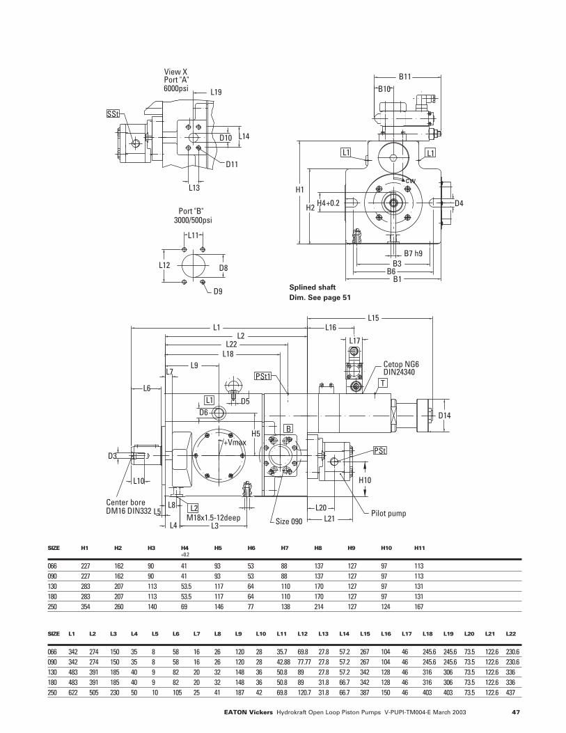
SIZE H1 H2 H3 H4 H5 H6 H7 H8 H9 H10 H11+0.2
066 227 162 90 41 93 53 88 137 127 97 113090 227 162 90 41 93 53 88 137 127 97 113130 283 207 113 53.5 117 64 110 170 127 97 131180 283 207 113 53.5 117 64 110 170 127 97 131250 354 260 140 69 146 77 138 214 127 124 167
SIZE L1 L2 L3 L4 L5 L6 L7 L8 L9 L10 L11 L12 L13 L14 L15 L16 L17 L18 L19 L20 L21 L22
066 342 274 150 35 8 58 16 26 120 28 35.7 69.8 27.8 57.2 267 104 46 245.6 245.6 73.5 122.6 230.6090 342 274 150 35 8 58 16 26 120 28 42.88 77.77 27.8 57.2 267 104 46 245.6 245.6 73.5 122.6 230.6130 483 391 185 40 9 82 20 32 148 36 50.8 89 27.8 57.2 342 128 46 316 306 73.5 122.6 336180 483 391 185 40 9 82 20 32 148 36 50.8 89 31.8 66.7 342 128 46 316 306 73.5 122.6 336250 622 505 230 50 10 105 25 41 187 42 69.8 120.7 31.8 66.7 387 150 46 403 403 73.5 122.6 437
B6
H2
H1
B3
B1
B7 h9
B11
H4
B10
D4+0.2
cw
L1 L1
L11
D8L12
L14D10
L13
D9
Pilot pump
D11
View X
3000/500psi
L19
Port "B"
SSt
6000psiPort "A"
T
Splined shaft
Dim. See page 51
48 EATON Vickers Hydrokraft Open Loop Piston Pumps V-PUPI-TM004-E March 2003
cw
L1 L1
B3B6B1
B13
H3
H2H1
B21
2
3
D4
D11 D9
Port "A" Port "B"
0
0
L11
D8L12
L13
D10L14
PumpDimensions -PVXS 066 - 250
Side ports - Proportional Valve Displacement ControlSPC03A.....E...
1. Proportional valve
2. Pressure limiter
3. Filter
G1/2”
G1/2”
G1/4”
Two drain ports, one supplied plugged
M18x1, 5x12-deep supplementary drain, or bleed plug.Must be drained in addition to if the pump is installedwith the shaft input end pointing upwards.
G1/4"x12.5-deep gauge port supplied pluggedMA
L2
L1
Mst
Pst
T
DIRECTION OF ROTATION CONTROL INPUT OUTPUT
Right Hand Rotation To + Vmax B ATo - Vmax A B
Left Hand Rotation To + Vmax A BTo - Vmax B A
SIZE SAE-FLANGE “B” SAE-FLANGE “A” WEIGHT3000(500)PSI, INLET 6000PSI, OUTLET KG
066 1 1/2’’ 1’’ 55090 2‘’ 1’’ 57130 2 1/2’’ 1’’ 111180 2 1/2’’ 1 1/4’’ 113250 3 1/2’’ 1 1/4’’ 226
SIZE B1 B2 B3 B4 B5 B6 B7 B8 B12 B13h9
066 210 116 160 235 130 180 10 116 — 165090 210 116 160 235 130 180 10 116 157.5 165130 260 140 200 265 224 224 14 140 — 190180 260 140 200 265 224 224 14 140 — 190 250 325 175 250 330 280 280 18 175 — 221
SIZE D1 D2 D3 D4 D5 D6 D7 DEEP D8 D9 DEEP D10 D11 DEEP D12h8 k6 Light Execution
066 125 38 M12 — 7/8-UNF M22x1.5 M10 20 38 M12 24 25 M12 21 —090 125 38 M12 18 7/8-UNF M22x1.5 M10 20 50 M12 24 25 M12 21 —130 160 50 M16 22 1 1/16-UNF M26x1.5 M12 20 62 M12 20 25 M12 20 M20180 160 50 M16 22 1 1/16-UNF M26x1.5 M12 20 62 M12 20 32 M14 20 M20 250 200 65 M20 26 1 1/16-UNF M33x2 M16 32 90 M16 32 32 M14 24 M24
Dimensions in mm
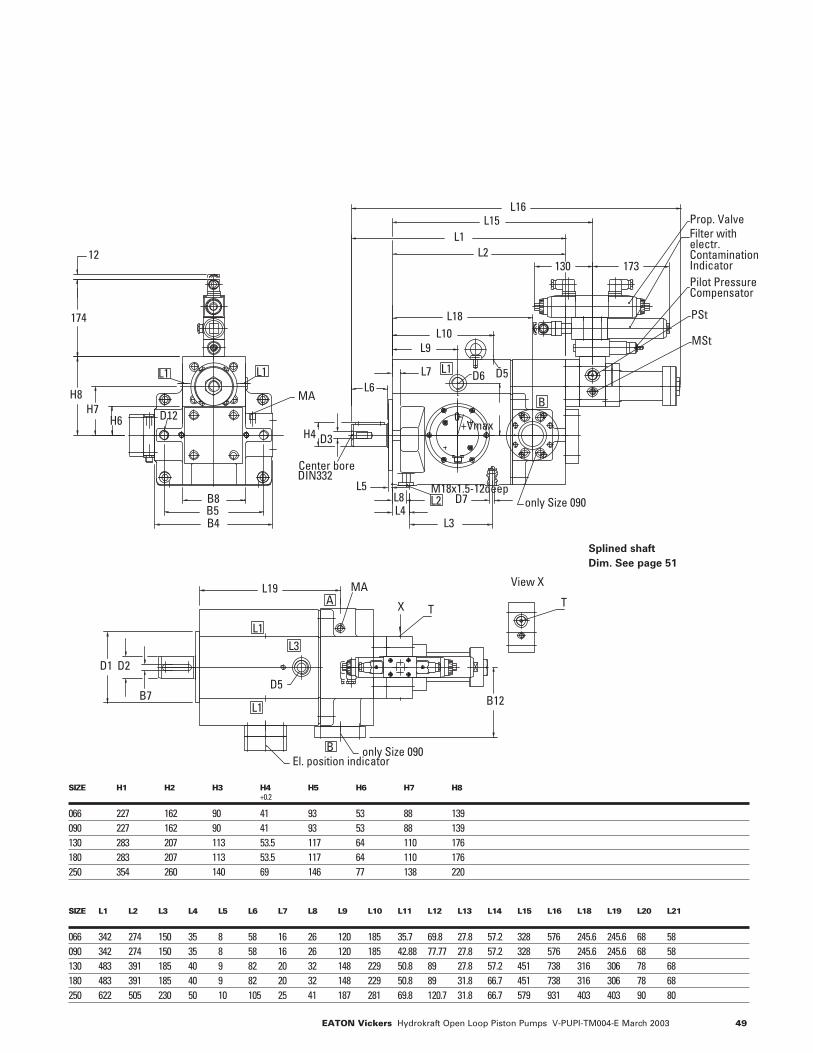
49EATON Vickers Hydrokraft Open Loop Piston Pumps V-PUPI-TM004-E March 2003
B8B5B4
D7
Center boreDIN332
MA
M18x1.5-12deep
+Vmax0
only Size 090
D12
D5D6
Prop. ValveFilter with electr.Contamination IndicatorPilot PressureCompensator
PSt
MSt
L2
L1 L1 L1
BH8
H7H6
12
174
H4
L3L4L8
D3
130 173
L5
L2
L18L10
L9
L7L6
L16L15
L1
El. position indicatoronly Size 090
MA
T
View X
T
D5
X
L1
L1
B
A
D1
B7
D2
L19
B12
L3
SIZE H1 H2 H3 H4 H5 H6 H7 H8+0.2
066 227 162 90 41 93 53 88 139090 227 162 90 41 93 53 88 139130 283 207 113 53.5 117 64 110 176180 283 207 113 53.5 117 64 110 176250 354 260 140 69 146 77 138 220
SIZE L1 L2 L3 L4 L5 L6 L7 L8 L9 L10 L11 L12 L13 L14 L15 L16 L18 L19 L20 L21
066 342 274 150 35 8 58 16 26 120 185 35.7 69.8 27.8 57.2 328 576 245.6 245.6 68 58090 342 274 150 35 8 58 16 26 120 185 42.88 77.77 27.8 57.2 328 576 245.6 245.6 68 58130 483 391 185 40 9 82 20 32 148 229 50.8 89 27.8 57.2 451 738 316 306 78 68180 483 391 185 40 9 82 20 32 148 229 50.8 89 31.8 66.7 451 738 316 306 78 68250 622 505 230 50 10 105 25 41 187 281 69.8 120.7 31.8 66.7 579 931 403 403 90 80
Splined shaft
Dim. See page 51
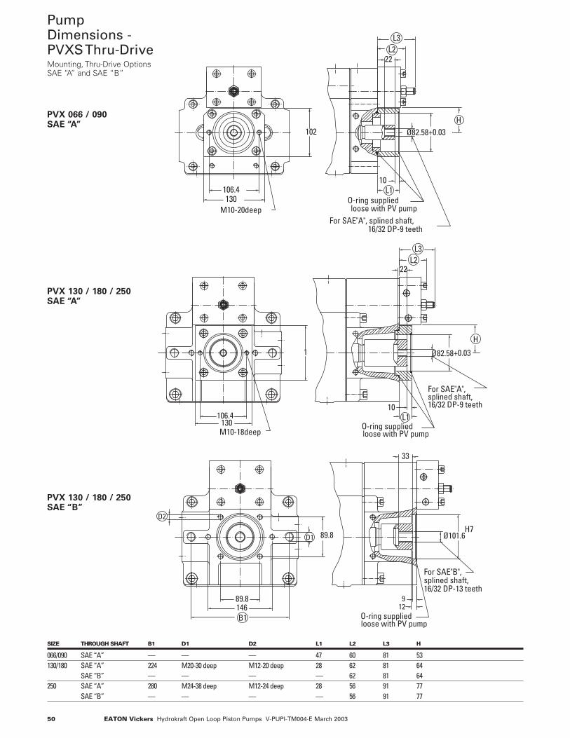
50 EATON Vickers Hydrokraft Open Loop Piston Pumps V-PUPI-TM004-E March 2003
B1
33
89.8
89.8146
Ø101.6D1
129
D2
For SAE"B", splined shaft,16/32 DP-13 teeth
O-ring suppliedloose with PV pump
H7
Ø82.58
L110
22L2
H
106.4
1
130
+0.03
L3
M10-18deep
For SAE"A", splined shaft,16/32 DP-9 teeth
loose with PV pumpO-ring supplied
HØ82.58
22
102
130106.4 L1
10
+0.03
L2L3
M10-20deep
16/32 DP-9 teethFor SAE"A", splined shaft,
loose with PV pumpO-ring supplied
PumpDimensions -PVXS Thru-Drive Mounting, Thru-Drive OptionsSAE “A” and SAE “B”
PVX 066 / 090SAE “A”
PVX 130 / 180 / 250SAE “A”
PVX 130 / 180 / 250SAE “B”
SIZE THROUGH SHAFT B1 D1 D2 L1 L2 L3 H
066/090 SAE “A” — — — 47 60 81 53130/180 SAE “A” 224 M20-30 deep M12-20 deep 28 62 81 64
SAE “B” — — — — 62 81 64250 SAE “A” 280 M24-38 deep M12-24 deep 28 56 91 77
SAE “B” — — — — 56 91 77
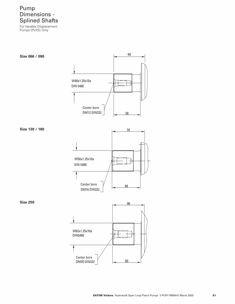
51EATON Vickers Hydrokraft Open Loop Piston Pumps V-PUPI-TM004-E March 2003
DIN5480W62x1.25x10a
90
80Center boreDM20 DIN332
78
68
W50x1.25x10a
DIN 5480
Center boreDM16 DIN332
Center boreDM12 DIN332
W40x1.25x10aDIN 5480
68
58
PumpDimensions -Splined Shafts For Variable DisplacementPumps (PVXS) Only
Size 066 / 090
Size 130 / 180
Size 250
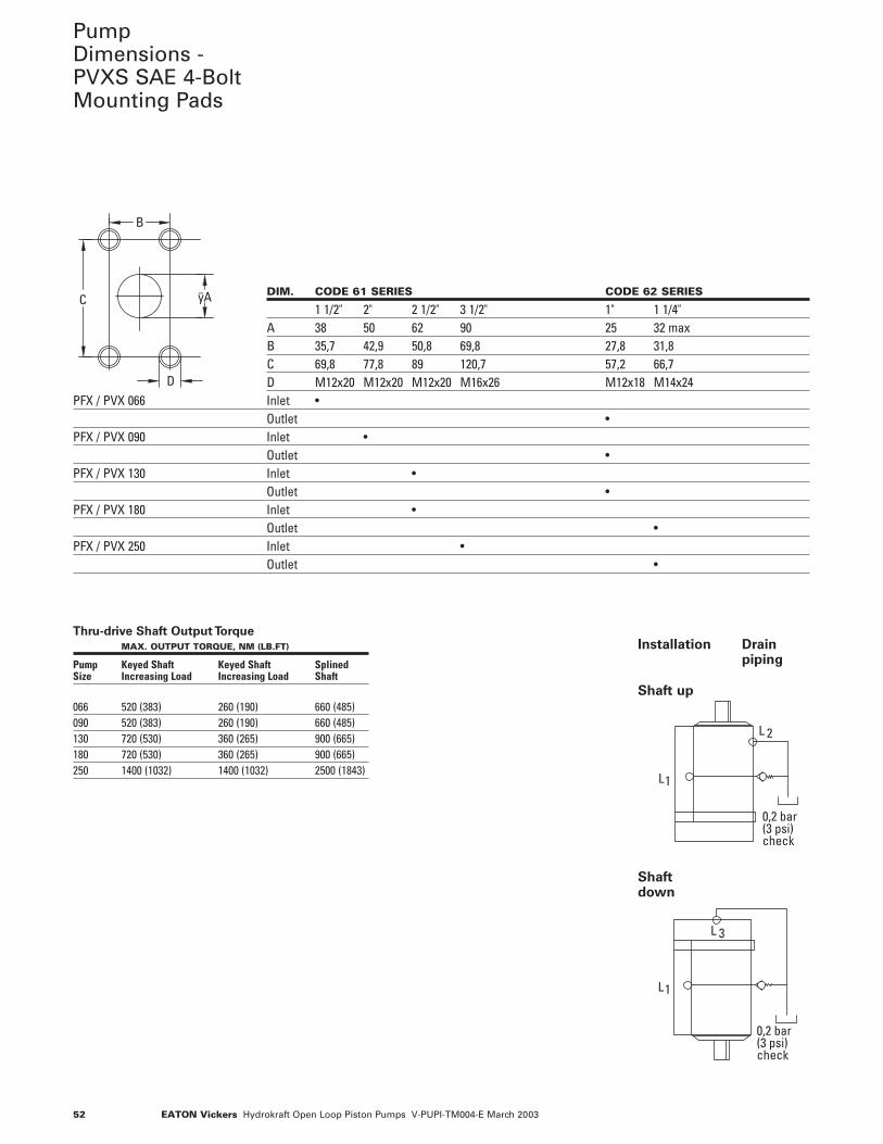
52 EATON Vickers Hydrokraft Open Loop Piston Pumps V-PUPI-TM004-E March 2003
PumpDimensions -PVXS SAE 4-BoltMounting Pads
1
2
0,2 bar (3 psi)check
L
L
1
0,2 bar (3 psi)check
3
L
L
DIM. CODE 61 SERIES CODE 62 SERIES
1 1/2" 2" 2 1/2" 3 1/2" 1" 1 1/4"A 38 50 62 90 25 32 maxB 35,7 42,9 50,8 69,8 27,8 31,8C 69,8 77,8 89 120,7 57,2 66,7D M12x20 M12x20 M12x20 M16x26 M12x18 M14x24
PFX / PVX 066 Inlet •Outlet •
PFX / PVX 090 Inlet •Outlet •
PFX / PVX 130 Inlet •Outlet •
PFX / PVX 180 Inlet •Outlet •
PFX / PVX 250 Inlet •Outlet •
D
B
C ÿA
Thru-drive Shaft Output Torque
MAX. OUTPUT TORQUE, NM (LB.FT)
Pump Keyed Shaft Keyed Shaft SplinedSize Increasing Load Increasing Load Shaft
066 520 (383) 260 (190) 660 (485)090 520 (383) 260 (190) 660 (485)130 720 (530) 360 (265) 900 (665)180 720 (530) 360 (265) 900 (665)250 1400 (1032) 1400 (1032) 2500 (1843)
Installation Drain piping
Shaft up
Shaftdown
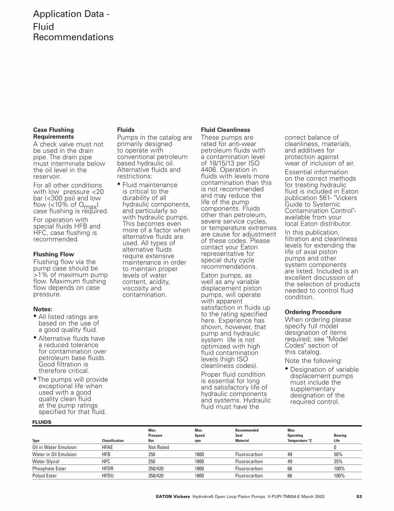
53EATON Vickers Hydrokraft Open Loop Piston Pumps V-PUPI-TM004-E March 2003
Application Data -FluidRecommendations
Case Flushing Requirements
A check valve must notbe used in the drainpipe. The drain pipemust interminate belowthe oil level in thereservoir.For all other conditionswith low pressure <20bar (<300 psi) and lowflow (<10% of Qmax)case flushing is required.For operation withspecial fluids HFB andHFC, case flushing isrecommended.
Flushing Flow
Flushing flow via thepump case should be>1% of maximum pumpflow. Maximum flushingflow depends on casepressure.
Notes:• All listed ratings are
based on the use of a good quality fluid.
• Alternative fluids havea reduced tolerance for contamination overpetroleum base fluids.Good filtration istherefore critical.
• The pumps will provideexceptional life whenused with a goodquality clean fluid at the pump ratingsspecified for that fluid.
Fluids
Pumps in the catalog areprimarily designed to operate withconventional petroleumbased hydraulic oil.Alternative fluids andrestrictions:• Fluid maintenance
is critical to thedurability of allhydraulic components,and particularly so with hydraulic pumps.This becomes evenmore of a factor whenalternative fluids areused. All types ofalternative fluidsrequire extensivemaintenance in orderto maintain properlevels of watercontent, acidity,viscosity andcontamination.
Fluid Cleanliness
These pumps are rated for anti-wearpetroleum fluids with a contamination level of 18/15/13 per ISO4406. Operation in fluids with levels morecontamination than thisis not recommended and may reduce the life of the pumpcomponents. Fluidsother than petroleum,severe service cycles, or temperature extremesare cause for adjustmentof these codes. Pleasecontact your Eatonrepresentative forspecial duty cyclerecommendations.Eaton pumps, as well as any variabledisplacement pistonpumps, will operate with apparentsatisfaction in fluids upto the rating specifiedhere. Experience hasshown, however, thatpump and hydraulicsystem life is notoptimized with high fluid contaminationlevels (high ISOcleanliness codes).Proper fluid condition is essential for long and satisfactory life ofhydraulic componentsand systems. Hydraulicfluid must have the
Fluid Cleanliness
correct balance ofcleanliness, materials,and additives forprotection against wear of inclusion of air. Essential information on the correct methodsfor treating hydraulicfluid is included in Eatonpublication 561- "VickersGuide to SystemicContamination Control"-available from your local Eaton distributor.In this publication,filtration and cleanlinesslevels for extending thelife of axial piston pumps and other system components are listed. Included is anexcellent discussion ofthe selection of productsneeded to control fluidcondition.
Ordering Procedure
When ordering pleasespecify full modeldesignation of itemsrequired; see "ModelCodes" section of this catalog.Note the following:• Designation of variable
displacement pumpsmust include thesupplementarydesignation of therequired control.
FLUIDS
Max. Max. Recommended Max Pressure Speed Seal Operating Bearing
Type Classification Bar rpm Material Temperature °C Life
Oil in Water Emulsion HFAE Not Rated 0Water in Oil Emulsion HFB 250 1800 Fluorocarbon 49 50%Water Glycol HFC 250 1800 Fluorocarbon 49 25%Phosphate Ester HFDR 350/420 1800 Fluorocarbon 66 100%Polyol Ester HFDU 350/420 1800 Fluorocarbon 66 100%

54 EATON Vickers Hydrokraft Open Loop Piston Pumps V-PUPI-TM004-E March 2003
Notes

55EATON Vickers Hydrokraft Open Loop Piston Pumps V-PUPI-TM004-E March 2003
Notes
Eaton14615 Lone Oak RoadEden Prairie, MN 55344USATel: 952 937-9800Fax: 952 974-7722www.hydraulics.eaton.com
Eaton20 Rosamond RoadFootscrayVictoria 3011AustraliaTel: (61) 3 9319 8222Fax: (61) 3 9318 5714
Eaton Dr.-Reckeweg-Str. 1D-76532 Baden-BadenGermanyTel: (49) 07221 682-0Fax: (49) 07221 682-788
Vickers© 2003 Eaton CorporationAll rights reserved Printed in USADocument No. V-PUPI-TM004-E March 2003