HYDROGEOLOGIC CHARACTERISTICS OF THE SURFICIAL …
105
STATE OF FLORIDA DEPARTMENT OF NATURAL RESOURCES Harmon Shields, Executive Director DIVISION OF INTERIOR RESOURCES Robert O. Vernon, Director BUREAU OF GEOLOGY Charles W. Hendry, Jr., Chief Information Circular No. 86 HYDROGEOLOGIC CHARACTERISTICS OF THE SURFICIAL AQUIFER IN NORTHWEST HILLSBOROUGH COUNTY, FLORIDA By William C. Sinclair Prepared by the UNITED STATES GEOLOGICAL SURVEY in cooperation with the BUREAU OF GEOLOGY DIVISION OF INTERIOR RESOURCES FLORIDA DEPARTMENT OF NATURAL RESOURCES and SOUTHWEST FLORIDA WATER MANAGEMENT DISTRICT TALLAHASSEE, FLORIDA 1974
Transcript of HYDROGEOLOGIC CHARACTERISTICS OF THE SURFICIAL …

STATE OF FLORIDADEPARTMENT OF NATURAL RESOURCES
Harmon Shields, Executive Director
DIVISION OF INTERIOR RESOURCESRobert O. Vernon, Director
BUREAU OF GEOLOGYCharles W. Hendry, Jr., Chief
Information Circular No. 86
HYDROGEOLOGIC CHARACTERISTICS OF THE SURFICIALAQUIFER IN NORTHWEST HILLSBOROUGH COUNTY, FLORIDA
By
William C. Sinclair
Prepared by the
UNITED STATES GEOLOGICAL SURVEY
in cooperation with the
BUREAU OF GEOLOGY
DIVISION OF INTERIOR RESOURCES
FLORIDA DEPARTMENT OF NATURAL RESOURCES
and
SOUTHWEST FLORIDA WATER MANAGEMENT DISTRICT
TALLAHASSEE, FLORIDA
1974

DEPARTMENT
OF
NATURAL RESOURCES
REUBIN O'D. ASKEWGovernor
RICHARD (DICK) STONE ROBERT L. SHEVINSecretary of State Attorney General
THOMAS D. O'MALLEY FRED O. DICKINSON, JR.Treasurer Comptroller
FLOYD T. CHRISTIAN DOYLE CONNERCommissioner of Education Commissioner of Agriculture
HARMON W. SHIELDSExecutive Director
ii
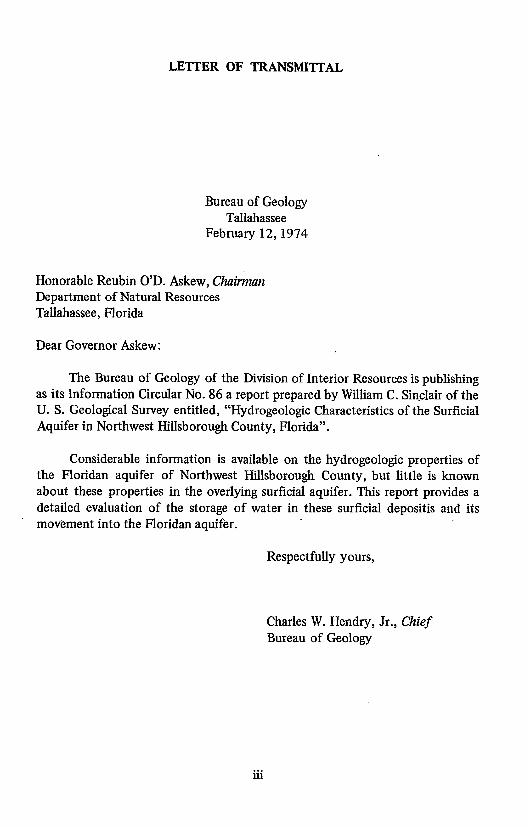
LETTER OF TRANSMITTAL
Bureau of GeologyTallahassee
February 12, 1974
Honorable Reubin O'D. Askew, ChairmanDepartment of Natural ResourcesTallahassee, Florida
Dear Governor Askew:
The Bureau of Geology of the Division of Interior Resources is publishingas its Information Circular No. 86 a report prepared by William C. Sinclair of theU. S. Geological Survey entitled, "Hydrogeologic Characteristics of the SurficialAquifer in Northwest Hillsborough County, Florida".
Considerable information is available on the hydrogeologic properties ofthe Floridan aquifer of Northwest Hillsborough County, but little is knownabout these properties in the overlying surficial aquifer. This report provides adetailed evaluation of the storage of water in these surficial depositis and itsmovement into the Floridan aquifer.
Respectfully yours,
Charles W. Hendry, Jr., ChiefBureau of Geology
111i

Completed manuscript receivedJanuary 11, 1974
Printed for the Florida Department of Natural ResourcesDivision of Interior Resources
Bureau of Geologyby Ambrose the Printer
Jacksonville, Florida
Tallahassee1974iv

CONTENTS
Page
Abstract ............................................. 1
introduction .... ...................................... 1
Geographic setting ..... ......... . ................. . .... . 2
Test drilling .............. ................................. 3Sampling methods ....................................... 5Laboratory analyses .................................... .. . 5
Particle-size analyses ....... .. .. .......... ............. ... 6Hydraulic conductivity . ...... .......................... 6Specific yield ........ .... ...... ........ .............. 7Clay and mineral identification ............................ 7
Lithology . ........................................... 7Natural-gamma logs ...................................... 8Geohydrology ......................................... 9
Limestone ... .............................. ...... 9
Clay . . . .... .. . .... ... .... .. .. .... ... . .... .. .. .. 10
Sand and clay ... ................................ . . .. 11
Sandy clay ........ ............. .. ............ . 11Clayey sand ..................................... .. 11Sand and clay laminae .............................. .. 12
Sand . ............... . ............................ 12
Hydrologic system ....................................... 13
Summary .. . .............................. ........ .. .. 16References cited. . .................. ............... ..... 19
v

ILLUSTRATIONS
Figure Page
I. Map of Northwest Hillsborough County, and adjoining counties showing
location of test sites and contours on the potentiometric surfaces of the
surficial and Floridan aquifers . . . . . . . . . . . . . . .... . . . . . . . ... . 4
TABLES
Table Page
1. Relationships of soil, terrain, geology, and hydrology at 59 test sites . . . . . . 20
2. Results of laboratory tests of 67 samples from 24 sites . . . . . . . . . . ... . 23
3. Clay-mineral identification for selected samples . . . . . . . . . . . . . ..... 26
4. Logs showing lithology, gamma radiation, and generalized geohydrology of
surficial deposits at sites tested in northwest Hillsborough County ...... ... 28
vi

HYDROGEOLOGIC CHARACTERISTICS OF THE SURFICIALAQUIFER IN NORTHWEST HILLSBOROUGH COUNTY, FLORIDA
ByWilliam C. Sinclair
ABSTRACT
Fifty-nine holes were augered to the top of the limestone FloridanAquifer. Lithologic and gamma logs of the holes were used in conjunction withlaboratory analyses of samples to define the hydrogeology of the unconsolidateddeposits of the surficial aquifer overlying the limestone. The surficial aquifer iscomprised of an upper fine sand unit which averages about 15 feet thick and alower sequence of sandy clay and clayey sand layers which average about 25 feetthick. Median grain size, specific yield, and vertical permeability of the surficialaquifer decrease downward. The coefficient of vertical permeability of the sandis about 100 gallons per day per square foot, but the coefficient of verticalpermeability of the lower sand and clayey sand is much lower ranging from 0.01to 0.1 gallon per day per square foot.
A confining layer of dense clay underlies the surficial aquifer separating itfrom the Floridan Aquifer below. The coefficient of vertical permeability of theclay is about 0.001 gallon per day per square foot. Although this clay isdiscontinuous, it averages 4 feet thick throughout 'the area and is apparently aweathering product of the underlying limestone. The limestone surface isirregular and its average depth is 45 feet below land surface.
The potentiometric surface in the surficial aquifer stands an average of 10feet above that in the Floridan. Leakage from the surficial aquifer to theFloridan occurs through the confining layer as well as through perforations inthe confining layer. Estimates of leakage to the Floridan Aquifer based onvertical permeability calculated at each test site varied widely from place toplace. A regional estimate, based on the average coefficient of verticalpermeability, is about 140,000 gallons per day per square mile.
INTRODUCTION
Heavy withdrawal of ground water from the Floridan Aquifer in northwestHillsborough and northeast Pinellas Counties, Florida, has lowered the watertable in the overlying surficial aquifer. The effects of the pumpage were anlayzedby Stewart (1968), and his analysis led the Southwest Florida WaterManagement District to request the U. S. Geological Survey to investigate thefeasibility of artificially recharging the Floridan Aquifer in the area.

2 BUREAU OF GEOLOGY
Considerable information is available on the hydraulic and hydrogeologicproperties of the Floridan Aquifer in this area but little has been known aboutthese properties in the overlying surficial aquifer. A principal aim of thisinvestigation is to provide a detailed evaluation of the role of the surficialdeposits in the storage of rain falling upon the land surface and its movementinto the Floridan Aquifer.
The investigation began in December 1968. This report, the first from theinvestigation, documents the results of test drilling undertaken to define thehydrologic characteristics of the unconsolidated deposits. These depositscomprise both the sands of the surficial aquifer, which is the water-table aquiferin the area, and the clay confining bed that retards movement of water betweenthis aquifer and the Floridan Aquifer below. The report is limited to descriptionof the methods used and interpretation of data derived from the test drilling.
GEOGRAPHIC SETTING
Northwest Hillsborough County is a flat to slightly undulating sandy plain.Its altitude is about 50 feet in the eastern part of the area of investigation; theregional slope westward toward and into the Gulf of Mexico, is about 4 feet permile.
The plain is perforated by sinkholes - circular depressions typical ofkarst erosion - - that bottom as much as 15 to 20 feet below land surface. Thesesmall circular depressions, locally called cypress heads or cypress domes, are oneof the most characteristic vegetative and geomorphic features of the gulf coastallowlands. These features result from local subsidence of the land surface due tosapping of the surficial material into solution openings forming in the underlyinglimestone. Sinkholes are prevalent throughout the area in all stages of formationranging from freshly collapsed pits a few feet in diameter to large lakes andswamps with irregular shorelines and bottoms - - composites of manycoalescent sinkholes. The sinks permit local hydraulic connection between thesurficial water-table aquifer and the Floridan Aquifer and are an importantavenue of natural recharge to the Floridan Aquifer in this area.
Most of the natural surface drainage of the area is poorly developed. Themyriad sinkhole swamps and lakes that dot the sandy plains fill when rainfall isheavy, then spill one into another as the water moves generally southwestward.Only a small part of the rainfall runs off and percolation to both aquifers is alsoslight. By far, the greatest part of rainfall in the area is lost by evaporation andtranspiration.

INFORMATION CIRCULAR NO. 86 3
TEST DRILLING
Sites were selected for test drilling on the basis of many criteria. Broadgeographical coverage seemed desirable to determine the variability of thesurficial deposits within the area. Test holes were drilled one-half mile to 1 mileapart from east of the Section 21 well field to the Cosme well field, and at about1-mile intervals both north and south of the Section 21 field (fig. 1). Within thisgeographical framework, sites were selected on different soils and landforms todetermine whether soil and terrain might give some indication of the lithology ofunderlying deposits. Table 1 lists several geologic and hydrologic factors at eachsite, for comparison. The "Soil Survey, Hillsborough County" (Dept.Agriculture, 1968) was used as authority for the soil type (table 1) at the testsites.
Much of the test drilling was concentrated within the 1-square-mile area ofthe Section 21 well field where the effects of pumping from the FloridanAquifer on water levels in lakes and in wells tapping the surficial aquifer aremost severe. Test holes were augered in Starvation Lake (site 31) where a12-foot decline in stage had exposed much of the bottom. A hole was alsoaugered near Jackson Lake (site 23) just west of Starvation Lake. In JacksonLake the stage did not seem to be fluctuating greatly. Test holes were augered inthe center of a well-defined sinkhole marsh (site 40), and in a well-definedsinkhole swamp (sites 32-35). Several wells were also augered in a flatwoods areawhere incipient sinkholes are developing (sites 26-28) and in soil types notpreviously augered. In all, 59 wells were drilled and sampled using the powerauger and one (site 60) was sampled at land surface by hand.
Where possible, wells were augered on Hillsborough County RoadDepartment rights-of-way. The upper few feet there is generally artificial fill sothe first sample was usually taken from 5 feet below land surface. Thecooperation of the Hillsborough County Engineer's Office, the city of St.Petersburg Water Department, and the many private citizens who allowed accessto their property is gratefully acknowledged.
Test sites where wells were drilled and sampled during this study arenumbered in sequence. At each site a well was installed using 2-inch plasticcasing with a screen set in the topmost part of the Floridan Aquifer. At mostsites a shallow well was also installed with the screen set in the surficial aquiferjust below the water table. Thus, measurements can be made of thepotentiometric surface of each aquifer.

O-f' 5l4' U1 0 ' N' mua''
0 60
PAC I'-- AS INT
SV OEXPLANATION R
i --- 40--- "
10 a53 8 mper \ > - --
011 i01,
S 1 3tie number 4aU40--1 -
09e 1"

INFORMATION CIRCULAR NO. 86 5
SAMPLING METHODS
The test holes were augered with a truck-mounted power rig. The augerflights are 5 feet long, 8 inches in diameter, and are formed around a 3-inchdiameter steel tube. A plug seals the bottom of the central tube during augering.This plug is held in place by 5-foot sections of steel rod. The steel rod is addedto the string, along with additional auger flights, as the hole is deepened. Whenthe auger bit reaches the desired sampling depth, the drill is stopped and the rodsare pulled out. The sampler is then lowered through the auger and pushed ordriven into the undisturbed material below the auger bit, cutting a cylindricalsample the diameter of the tube.
The sampler used is called a split spoon and is made of two half tubes thatfit together to form a cylinder and are held together by a threaded coupling atthe top and a threaded, case-hardened, cylindrical cutting shoe at the bottom.Three aluminum tubes 6 inches long and 1½ inches in diameter fit snugly into it.When the sample is retrieved, the split spoon is opened. The aluminum tubes aresealed at each end with plastic caps and labeled. The ends of the tubes are sealedin wax to prevent loss of moisture and disturbance of the sample before itreaches the laboratory.
Sampling unconsolidated material through a hollow-stem auger is superiorto sampling by other methods because uncontaminated samples can be obtainedat any desired depth in a relatively undisturbed condition. Most samples of clayand laminated clay and sand show the extent of disturbance by drag folds in the
bedding planes at the cylinder walls. The clay is soft, and undisturbed sampleswere usually collected without difficulty. Because massive sand has littlecohesion, undisturbed samples are nearly impossible to obtain from below thewater table. The sand is homogeneous and the amount of disturbance is difficultto determine.
Samples were usually taken at 5-foot intervals. Test holes at sites 35, 37,40, and 44 were sampled continuously from land surface to limestone. Thelithologic logs of these test holes indicate that samples collected every 5 feetwould prove adequate for the needs of this study when augmented by gammalogs.
LABORATORY ANALYSES
Sixty-nine samples from 25 of the test holes were analyzed by theGeological Survey's laboratory in Denver for certain physical and hydrologicparameters.

6 BUREAU OF GEOLOGY
PARTICLE-SIZE ANALYSES
In unconsolidated, granular material, the hydraulic conductivity is largelya function of the size and shape of the component grains and their degree ofsorting. The median diameter is the particle size that is larger than 50 percent ofthe sample and smaller than the other 50 percent. The median diameter of thesamples tested ranged from 0.002 mm (millimeter) for dense clay to 0.22 mmfor sand and mixtures of sand and clay (table 2). The average of all the mediandiameters was 0.14 mm, and for the samples without an appreciable silt and clayfraction, 0.17 mm. These sizes are in the fine sand range (0.125 to 0.25 mm) ofthe Wentworth classification (Twenhofel and Tyler, 1941, p. 46-48, andWentworth, 1922). Sand particles of medium size (0.25 to 0.5 mm) rarelyconstituted more than 2 or 3 percent of the samples except for sample 23-351/which contained 16.8 percent. That fraction within the coarse sand size (0.5 to1.0 mm) was less than 1 percent of any sample.
The sorting coefficient listed in table 2 is a measure of the degree ofsorting in a sample. It is sometimes called the geometrical quartile deviation(Trask, 1932, p. 70-72). It is represented by the expression (Q3/Ql)½ in whichQ3 is the particle diameter that is larger than 75 percent of the sample, and Q1 isthe particle diameter that is larger than 25 percent of the sample. A sortingcoefficient less than 2.5 (Krumbein and Pettijohn, 1938, p. 232) indicates a wellsorted material. Most of the sorting coefficients listed in table 2 are less than 2.5,indicating that most of the samples are well sorted.
HYDRAULIC CONDUCTIVITY
Hydraulic conductivity is the capacity of a material to transmit water.Hydraulic conductivity is reported in table 2 as the rate of flow, in cubic feet perday, through a cross-sectional area of 1 square foot, under a hydraulic gradientof 1 foot per foot, at the prevailing kinematic viscosity in units of feet per day.This terminology is suggested for use in reports of the Geological Survey byLohman, and others, (1972). The coefficient of permeability is also reported inMeinzer Units, the former standard of the Geological Survey - - gallons per dayper square foot, under a hydraulic gradient of 1 foot per foot at a temperatureof 600 F.
Hydraulic conductivity of 36 samples was determined in the laboratoryusing either constant-head or variable-head permeameters. The conductivity of
11 Sample numbers are a composite of the site number and sample depth. For example,sample 23-35 is from a test well at site 23 and from a depth of 35 feet.

INFORMATION CIRCULAR NO. 86 7
one clay sample was determined by a consolidation test. Because most of thetests were made on undisturbed material in the collection tube, the data cited intable 2 represent vertical permeability.
SPECIFIC YIELD
The specific yield of a material was defined by Meinzer (1923, p. 28) as"the ratio of (1) the volume of water which, after being saturated, it will yieldby gravity to (2) its own volume". In applying laboratory results to fieldproblems specific yield is commonly taken as a measure of the capacity of awater-table aquifer to store water.
The specific yields listed in table 2 were determined as thecentrifuge-moisture equivalent. This equivalent is the moisture content of asample after it has been saturated with water and then subjected for 1 hour to aforce 1,000 times that of gravity. Such specific yields represent extreme degreesof dewatering and are higher than specific yields of the same materials underfield conditions.
Specific yields decrease with increasing silt and clay content. Averagespecific yield for the sand sample is 34.6 percent for clayey sand, 28.9 percent;and for sandy clay, 19.1 percent. The specific yields of 11 samples of laminatedsand and clay range from 22.4 to 37.4 percent. This variation reflects a widerange in clay content and degree of sorting within this unit. Specific yields
determined for three samples of clay average 10.4 percent. The specific yield ofanother clay sample is 53.6 percent. This sample is a black, organic fluid clayfound in solution openings in the upper part of the Floridan Aquifer.
CLAY - MINERAL IDENTIFICATION
Ten samples of clay were submitted to the laboratory for identification.The identifications, listed in table 3, show mixed-layered illite-montmorillonite,with illite generally predominant.
LITHOLOGY
The lithologic descriptions of the samples in table 4 were made at the testsite. Observations were made of the properties that affect the hydrology of the
sediments - - particle size, shape, sorting, clay content, and stratification. Color
was also noted as an aid to interpretation of the environment of deposition; thedegree of weathering; the presence of organic matter; and other pertinent factors
significant to the geohydrology.
8 BUREAU OF GEOLOGY
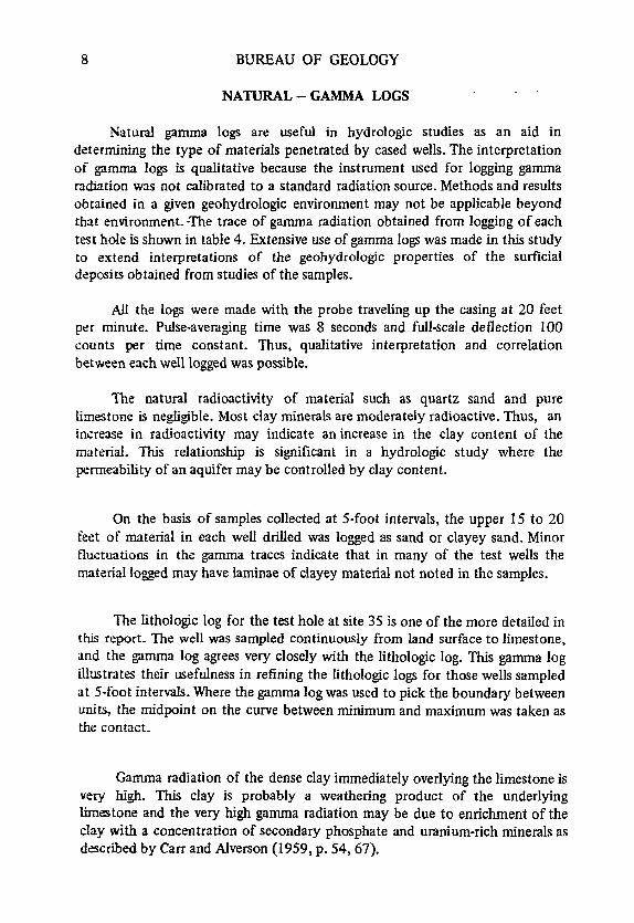
NATURAL - GAMMA LOGS
Natural gamma logs are useful in hydrologic studies as an aid indetermining the type of materials penetrated by cased wells. The interpretationof gamma logs is qualitative because the instrument used for logging gammaradiation was not calibrated to a standard radiation source. Methods and resultsobtained in a given geohydrologic environment may not be applicable beyondthat environment. -The trace of gamma radiation obtained from logging of eachtest hole is shown in table 4. Extensive use of gamma logs was made in this studyto extend interpretations of the geohydrologic properties of the surficialdeposits obtained from studies of the samples.
Al the logs were made with the probe traveling up the casing at 20 feetper minute. Pulse-averaging time was 8 seconds and full-scale deflection 100counts per time constant. Thus, qualitative interpretation and correlationbetween each well logged was possible.
The natural radioactivity of material such as quartz sand and purelimestone is negligible. Most clay minerals are moderately radioactive. Thus, anincrease in radioactivity may indicate an increase in the clay content of thematerial. This relationship is significant in a hydrologic study where thepermeability of an aquifer may be controlled by clay content.
On the basis of samples collected at 5-foot intervals, the upper 15 to 20feet of material in each well drilled was logged as sand or clayey sand. Minorfluctuations in the gamma traces indicate that in many of the test wells thematerial logged may have laminae of clayey material not noted in the samples.
The lithologic log for the test hole at site 35 is one of the more detailed inthis report. The well was sampled continuously from land surface to limestone,and the gamma log agrees very closely with the lithologic log. This gamma logillustrates their usefulness in refining the lithologic logs for those wells sampledat 5-foot intervals. Where the gamma log was used to pick the boundary betweenunits, the midpoint on the curve between minimum and maximum was taken asthe contact.
Gamma radiation of the dense clay immediately overlying the limestone isvery high. This clay is probably a weathering product of the underlyinglimestone and the very high gamma radiation may be due to enrichment of theclay with a concentration of secondary phosphate and uranium-rich minerals asdescribed by Carr and Alverson (1959, p. 54, 67).

INFORMATION CIRCULAR NO. 86 9
Phosphate and uranium analyses were not made during the currentinvestigation but sample 37-36 (table 3) contains 2-3 percent of potash feldspar.Potassium-40 is a common source of high gamma radiation in feldspars and inclays formed by their decomposition.
At site 40, a thick section of peat and organically-rich clay was penetrated,and at site 21 about 20 feet of dense clay was countered. The gamma logs for
both sites show that neither the peat nor the clays have appreciableradioactivity. No explanation is apparent for these anomalous logs but theyindicate that the gamma log alone is not always a reliable indicator of lithology.
GEOHYDROLOGY
Laboratory analyses and field observations were used to determine the
hydrologic characteristics of the material underlying the area of investigation.The material is divided into four major geohydrologic units: (1) limestone; (2)
clay; (3) sand and clay; and (4) sand. The geohydrologic units are listed in table
4.
LIMESTONE
The Tampa Limestone is the consolidated bedrock immediately underlyingthe surficial deposits throughout the area studied, and is the upper unit of the
Floridan Aquifer. The limestone is gray or light tan to white, usually sandy,
fossiliferous in places and commonly contains clay lenses and cavities. The
limestone is dense and hard; especially where sandy, but may be soft at places
where badly weathered. Commonly, the upper surface of the limestone is case
hardened by impregnation with silicon dioxide.
Cavities in the upper few feet of the limestone were penetrated by theauger at several sites. These cavities were commonly filled with a black clay. The
black color indicates an organic origin; a sapropel, or gyttja, which may have
flowed into the cavernous limestone through connection with swampy sinkholes.
This clay is extremely soft and fluid as though it were not part of the aquifer
structure. Sample 23-40 (table 2); which seems typical of this clay, had a specific
yield- of 53.6 percent, suggesting that it may have been intruded into its present
position under artesian pressure.
Permeameter tests, made on two samples of limestone indicated
coefficients of permeability of 0.1 and 15 gpd per ft2 . The actual range in
permeability of the limestone is much greater because of variations in lithology,the degree of weathering, and because most movement of water through
limestone is principally along enlarged bedding planes and joints. Tests of wells

10 BUREAU OF GEOLOGY
in the Tampa Limestone indicate that the coefficient of permeability of thelimestone in the test area is about 1,000 gpd per ft2 .
CLAY
A dense, plastic clay overlies the Tampa Limestone throughout the areaand is often interbedded with thin layers of limestone in the upper part of theFloridan Aquifer. The clay is generally green or greenish-gray, is streaked ormottled with gray and black, and contains sand. The sand fraction in the 6samples analyzed averaged 44 percent, and ranged from 22 percent to 64percent.
The clay may be calcareous in places, particularly near the limestonecontact. Clay, as described above, was penetrated in 47 of the 59 test holes.Where present, it is as much as 20 feet thick and averages about 4 feet.
The laboratory analyses of the clay minerals are similar to those obtainedby Cart and Alverson (1959, p. 32) for clay minerals in west-central Florida.Carr and Alverson also show (1959, p. 52-53, fig. 14) with sand-clay ratios of theclay and unweathered limestone that the clay is a residuum of the underlyingTampa Limestone. They postulate 5 to 10 feet of original limestone for eachfoot of residual clay.
Other evidence that indicates the clay is a weathered residuum of theTampa Limestone is (1) the presence of distorted and crenulated bedding planesin the clay resulting from slumping and collapse of underlying material; (2) theoccurrence of fresh chert; and (3) the clay's high gamma radiation.
Carr and Alverson (1959) attribute the high gamma radiation touranium-rich minerals concentrated by dissolution of the Tampa Limestone andpossibly by leaching of these minerals from the younger Hawthorn and BoneValley Formations. Although the Hawthorn and Bone Valley Formations werenot identified in the test drilling, they probably once overlay the TampaLimestone in this area as they do the Tampa Limestone in much of west-centralFlorida.
Samples collected at any depth expand somewhat when the overburdenload is removed. The result is that the porosity and permeability, as determinedin the laboratory, generally seem to be higher than expected for the material inplace. This is particularly true of samples of plastic clay. Consolidation tests,although time consuming and expensive, yield values of permeability which moreclosely represent natural conditions because this test permits adjustment for theoverburden load. Clay sample 17-65, selected as typical by comparing several

INFORMATION CIRCULAR NO. 86 11
differential thermal analyses, was subjected to a consolidation test and thecoefficient of vertical permeability, adjusted for an overburden load of 60 psi(pounds per square inch), was about 0.001 gpd per ft2 .
Permeability will vary within the clay because of differences in the sandcontent, the degree of compaction and the structure as well as many otherfactors. However, these variations are minor. Therefore, the coefficient ofpermeability obtained from the consolidation test, 0.001 gpd per ft2 , isconsidered representative of the vertical permeability of the clay layer in thearea.
SAND AND CLAY
A sequence of sand and clay layers lies unconformably on the erodedsurface of the weathered clay residuum or the limestone where the clay isabsent. The mottles and crenulations which are common in the dense clay areabsent in the laminated sand and clay. Stratification in this unit is apparentlyundisturbed, indicating that deposition occurred after that period of weatheringof the Tampa Limestone represented by the dense clay.
The hydrologic characteristics of this unit vary greatly with the claycontent of the material and with the degree of stratification. Vertical and lateralchanges in composition are abrupt within the section.
Material comprising the sand and clay unit has been subdivided, for betterdefinition of hydrologic properties, into three geohydrologic subunits: sandyclay, clayey sand, and sand and clay laminae.
SANDY CLAY
The term sandy clay is used to define material in which clay fills theinterstices between sand grains. The proportion of clay is not high enough togive the material a plastic cohesiveness characteristic of the underlying residualclay. In four samples of this unit tested by the laboratory, the silt-clay fractionranged from 24.3 to 42.9 percent. The coefficients of vertical permeability ofthese samples ranged from 0.0013 to 0.16 gpd per ft2 . For this study, a value of0.01 gpd per ftz was taken as a reasonable average coefficient of verticalpermeability of the material logged as sandy clay.
CLAYEY SAND
Clayey sand is the term used to describe that part of the laminatedsequence which is chiefly sand but contains sufficient clay to have a significant
12 BUREAU OF GEOLOGY
effect on its permeability. The clay appears to be evenly dispersed throughoutthe material. Silt and clay content of 10 samples of the clayey sand ranged from8.2 to 25.4 percent and averaged 14.6 percent. The coefficient of verticalpermeability of 6 samples whose clay content ranged from 12.2 to 20.0 percentranged from 0.021 to 9.8 gpd per ft2 . A value of 1 gpd per ft2 is a reasonableaverage for the clayey sand throughout the area.
SAND AND CLAY LAMINAE
The term sand and clay laminae is used to define material that ispredominantly sand or clayey sand but is banded with distinct layers of sandyclay or clay. Individual layers of clay are as much as 1 centimeter thick. The siltand clay content of the six samples for which the coefficient of verticalpermeability was also determined ranged from 10.7 to 19.4 percent. The verticalcoefficient of permeability of these samples ranged from 0.0069 to 0.49 gpd perft2 , and 0.01 gpd per ft2 is a reasonable average.
The silt and clay content of the sand and clay laminae at site 60 issomewhat less than at other sites and ranges from 7.0 to 9.1 percent.Coefficients of horizontal permeability of the samples from site 60 ranged from83 to 29 gpd per ft2 ; with one anomalous value of 120 gpd per ft2 . Evenexcluding the anomalous value, the average for the horizontal permeabilities ismore than 16 times greater than that of the average vertical permeability of theother sand and clay subunits.
The low vertical permeability of the subunit is caused by stratification.Although silt and clay comprise a small fraction of the total sample, theirconcentration in horizontal layers greatly retards vertical movement of waterthrough the unit. The thin layers of dense clay have more effect on the verticalpermeability than would a larger amount of clay evenly dispersed through thesand.
SAND
The uppermost deposit underlying the study area is a clean well-sorted,fine to very fine quartz sand. The sand has no apparent bedding and isnoncohesive except for a zone of cementation which occurs at places near thesurface. The sand ranges from 0 to 35 feet in thickness and averages about 16feet. It is absent at only one site. The sand is commonly white to light tan orbuff colored near the surface where it often contains a mixture of organic matterand silt.

INFORMATION CIRCULAR NO. 86 13
The clay content of the massive sand unit seems to increase gradually withdepth. This clay may have been reworked by wave action on the underlyinglaminated sand and clay unit thus obscuring the contact. It is also possible thatthe sand may be a near-shore facies of the underlying unit.
The lithologic descriptions of the sand in table 4 were verified bylaboratory analyses. Particle-size analyses of 19 samples show that the silt andclay fraction ranges from 0.2 to 6.8 percent. All the samples are within the finesand classification of Wentworth (median diameter 0.125 to 0.25 mm). Theaverage of the median grain size for all samples was 0.17 mm. The coefficient ofvertical permeability of five samples ranged from 2.7 where the silt clay contentwas 4.7 percent to 98 gpd per ft 2 where the silt clay content was 0.9 percent.An aquifer test made in the surficial aquifer indicates that the horizontalcoefficient of permeability of this sand is about 100 gpd/ft2 . That value isconsidered a reasonable average for the unit.
HYDROLOGIC SYSTEM
In northwest Hillsborough County surficial sand of relatively highpermeability and large storage capacity is underlain by layers of sand and clay ofless permeability and storage capacity. Underlying these units is a relativelyimpermeable clay which overlies the permeable limestone of the FloridanAquifer and is the most important factor in retarding the downward movementof water from the surficial aquifer to the Floridan Aquifer.
A common method of calculating the composite coefficient of verticalpermeability of a section is by the equation (modified from DeWiest, 1965, p.231):
Pv = M
ml/P1 + m 2 /P 2 + - - - - mn/Pn
where Pv is the composite coefficient of vertical permeability for allconfining layers,
M is the total thickness of all confining layers,m is the thickness of each confining layer,p is the coefficient of permeability of the confining layers as
described in the preceding sections.
For example, well 23 in table 4 is shown to penetrate 4 feet of clay, 8 feetof sandy clay, 16 feet of sand and clay laminae, and 11 feet of sand. The clayand sandy clay are considered to be confining layers because of their lowcoefficients of permeability; 0.001 and 0.01 gpd per ft2 . Although the vertical

14 BUREAU OF GEOLOGY
permeability of the sand and clay laminae is also low, this subunit is considered apart of the aquifer along with the 11 feet of sand, because of the high horizontalpermeability. Substituting the values from the log of well 23 into the equation: :
Pv = 4+8
4/0.001 + 8/0.01
= 124800
= 0.0025 gpd per ft2
The clay, with a coefficient of permeability of 0.001 gpd per ft2 , is thedominant factor in the equation controlling the composite vertical permeabilityof the surficial deposits.
The values of composite coefficients of vertical permeability divided bythe confining layer thickness are listed in table 1 where they are called leakagefactors. These range from 0.3 x 10 4 to 33.0 x 10⁻⁴ and average 4.9 x 10⁻⁴
gpd/ft3 .
Estimates of leakage from the surficial aquifer through the confining bedto the Floridan Aquifer may be made by multiplying the leakage factor by thedifference in head in the two aquifers. For example: assuming a head differenceof 10 feet and using the average factor given above, than 10 ft x .00049 gpd/ft3
= .0049 gpd/ft2 . Leakage over 1 square mile, under these conditions would beabout 140,000 gallons per day.
Inter-aquifer leakage is commonly estimated from aquifer test data. Cherryand others (1970, p. 60) report a leakage factor of 1.5 x 10⁻³ on the basis of along-term aquifer test on a well in the Section 21 well field. This leakage factoris an order of magnitude larger than 4.9 x 10 -4 - the average of the valuescalculated from the well logs throughout the area. Data collected from the testdrilling are biased by the location of the test sites (relatively few were drilled insinkholes, swamps, and lake bottoms) just as aquifer-test data are biased by thelocation of the pumped well. In the absence of an infinite number of test sites oraquifer tests, the true value of regional leakage can only be approached byjudicious interpretation of the available data.
Variations in the composite vertical permeability are large within shortdistances because of the variations in the thickness of the dense clay layer.Variations in clay thickness may result from local variations in the rate ofdissolution of the underlying limestone which, in turn, may be due to local

INFORMATION CIRCULAR NO. 86 15
variations in limestone lithology. Variations in the topography of the limestonesurface just before the onset of karst erosion represented by the'clay may alsoaffect the thickness of the clay layer. The clay may have been subject tosubaerial erosion prior to the deposition of the sand and clay unit and toremoval by subsidence into active sinkholes.
Study of the logs in table 4 indicates that at least three generations ofsinkholes exist; relict, established, and incipient. Sinkholes apparently developedin the surface of the Tampa Limestone before deposition of the sand and clayunit. Sites 17 and 44, for example, are flatwood areas with no surface indicationof sinkhole development. The logs of the wells drilled at sites 17 and 44 (table 4)indicate a swampy environment at depth. These deposits are overlain by the sandand clay and the sand. The limestone surface in these wells was found 35 and 20feet lower than the limestone surface encountered at the nearest adjacent testsites. The sinkholes penetrated by these wells are relict.
Well 40 was drilled within a circular marsh - - an established sinkhole ofat least 50-years duration, judging from the size of the cypress trees. Well 40penetrated more than 60 feet of black clay and peat and had not reachedlimestone at 107 feet below land surface. Nearby wells penetrate limestone at 45feet on the average.
The appearance of incipient sinkholes, some only a few feet in diameter,attest to the stoping of surficial sediments into newly developing solutioncavities in the limestone. Many of the incipient sinks have developed surfaceexpression since the beginning of this study in 1968.
Although natural recharge occurs more rapidly through perforations in theconfining layer than where the clay is intact, sinkholes occupy a smallpercentage of the total area and leakage through the clay confining layer,although slower, probably constitutes the major part of natural recharge to theFloridan Aquifer in the area.
Variations in thickness of clay.and in depth to the limestone surface are sogreat over such short distances that very close spacing of test holes would benecessary to delineate any pattern. No relations were discovered among surfaceterrain, vegetation or soil type and the types of materials penetrated in test wellswhich might aid in predicting the nature of these materials from surfaceexpressions in places where there are no test wells. Circular depressions, swamps,and lakes are presumed to represent sinkholes which perforate the clay layer and
permit hydraulic connection between the aquifers. Many of these features maybe underlain by plugged sinkholes and, conversely, active sinks may exist thathave not yet developed any surface expression.

16 BUREAU OF GEOLOGY
The contours on the potentiometric surfaces of the surficial aquifer andthe upper part of the Floridan Aquifer (fig. 1) show the difference in water levelbetween the two. The potentiometric surface of the surficial aquifer is rarelymore than 10 feet below land surface and is commonly less than 5 feet.Contours on the potentiometric surface of the surficial aquifer generally reflectthe configuration of the land topography. The contours slope gently from analtitude of about 60 feet in the northeastern part of the area southwestwardtoward Tampa Bay and the gulf.
The potentiometric surface in the upper part of the Floridan Aquifer inthis area stands 5 to 10 feet lower than that of the surficial aquifer (the watertable) under natural conditions. The artesian head is a function of the altitude ofthe water table, the resistance to vertical movement of water from the surficialaquifer through the confining layer to the Floridan Aquifer, and the resistanceto horizontal movement of water through the Floridan Aquifer.
Near the Section 21 well field where data are sufficient to define bothpotentiometric surfaces in detail, a depression in the water table overlies thecone of depression in the Floridan Aquifer. The latter depression is due topumpage from the Floridan Aquifer and the former to leakage induced by theincreased head difference between the two aquifers.
The minor depression in the water table southeast of the well field may bedue to the absence of the confining layer in this area and a consequent high rateof leakage to the Floridan Aquifer. The logs of test wells in this area show thatthe limestone is at a shallow depth and is overlain directly by the surficialaquifer.
Just east of the well field, Lakes Charles, Saddleback, and Round areartificially maintained at stages between 50 and 55 feet by pumpage from theFloridan Aquifer. Seepage from the lakes maintains the potentiometric surfaceof the surficial aquifer at a relatively high level in this area even thoughconsiderable leakage to the Floridan Aquifer is also taking place. The effects ofthis leakage on the potentiometric surface of the Floridan Aquifer are notobvious because of the relatively high permeability of the limestone.
SUMMARY
Northwest Hillsborough County is underlain by a surficial sand(water-table) aquifer that has a large capacity to store water. The sand becomesless permeable with depth and grades downward through a sequence of sand andclay layers. Although the sand and clay is an important part of the surficialaquifer, the vertical permeability of the lower unit is low because of the

INFORMATION CIRCULAR NO. 86 17
horizontal laminae of clayey sand and sandy clay. A dense, plastic clay underliesthe sand and clay unit throughout most of the area. The clay, a weatheringproduct of the underlying limestone, forms a confining layer because of itsextremely low permeability and is the most important factor in retarding thedownward movement of water from the surficial to the Floridan Aquifer.
Lithologic logs based on auger samples taken at 5-foot intervals incombination with natural-gamma logs adequately defined the components of thesurficial aquifer system and the confining bed.
Laboratory tests of the size, sorting, permeability and storage capacity ofsamples of sediments of the surficial aquifer and confining bed were useful inestimating field values for the various geohydrologic units. The values of verticalcoefficient of permeability thus calculated vary widely but are useful in makingregional estimates of infiltration capacity or in calculating the rate of recharge tothe Floridan Aquifer from the overlying surficial aquifer.

I8 BUREAU OF GEOLOGY
INFORMATION CIRCULAR NO. 86 19
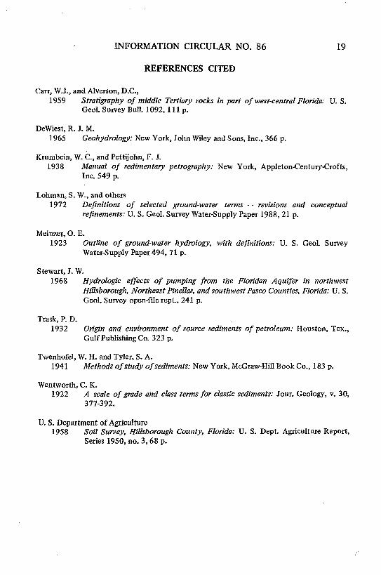
REFERENCES CITED
Carr, W.J., and Alverson, D.C.,1959 Stratigraphy of middle Tertiary rocks in part of west-central Florida: U. S.
GeoL Survey Bull. 1092, 111 p.
DeWiest, R. J. M.1965 Geohydrology; New York, John Wiley and Sons, Inc., 366 p.
Krumbein, W. C., and Pettijohn, F. J.1938 Manual of sedimentary petrography: New York, Appleton-Century-Crofts,
Inc. 549 p.
Lohman, S. W., and others1972 Definitions of selected ground-water terms - - revisions and conceptual
refinements: U. S. Geol. Survey Water-Supply Paper 1988, 21 p.
Meinzer, O. E.1923 Outline of ground-water hydrology, with definitions: U. S. Geol. Survey
Water-Supply Paper 494, 71 p.
Stewart, J. W.1968 Hydrologic effects of pumping from the Floridan Aquifer in northwest
Hillsborough, Northeast Pinellas, and southwest Pasco Counties, Florida: U. S.Geol. Survey open-file rept., 241 p.
Trask, P. D.1932 Origin and environment of source sediments of petroleum: Houston, Tex.,
Gulf Publishing Co. 323 p.
Twenhofel, W. H. and Tyler, S. A.1941 Methods of study of sediments: New York, McGraw-Hill Book Co., 183 p.
Wentworth, C. K.1922 A scale of grade and class terms for elastic sediments: Jour. Geology, v. 30,
377-392.
U. S. Department of Agriculture1958 Soil Survey, Hillsborough County, Florida: U. S. Dept. Agriculture Report,
Series 1950, no. 3, 68 p.

20 BUREAU OF GEOLOGY

table 1. Relationship of soil, terrain, geology and hydrology at 59 test sites(gpd per ft 3: gallons per day per square foot per foot)
Altitude of
Test, Altitude (feet) Clay Leakage p6tentiometric Datesite Soil Terrain Land Tp of-' thickness facto; surface of
number- type surface limestone (feet) gpd per ft xl0" Florid( Suial measurementFloridan Surficial'Aquifer aquifer
1 Leon flat, lakeshore 44.4 -19 14 0.7 33.32 41.39 12-12-712 Blanton upland, interlake 47.9 -20 0 33. 40.40 ---3 Leon flat, interlake 47.7 -19 2 2.9 27.14 39.58 11-05-714 Blanton slope, lakeshore 48.3 - 2 5 2.0 .--- 35.10 -- -
5 Leon extensive flatland 64.4 29 4.5 2.2 59.36 59.99 05-18-710
6 Leon flat, interlake 50.6 - 4 0 10.0 ---- 49.23 11-05-69S7 Leon flat, interlake 52.5 , 1 8 1.3 35.46 44.21 05-18-71
8 Ona flat, interlake 51.4 6 3 3.3 -- 49.95 11-05-699 Ona flat, interlake 50.1 -10 10 0.9 35.53 47.30 11-05-69
10 Leon flat, interlake 56.1 - 6 6 1.4 37.73 51.33 05-18-71
11 Leon low drainageway 57 17 0 5.0 49.5 54.0 05-16-7012 Leon flat, interlake 56.3 5 6 1.7 34.4 ---- 05-16-70 g13 Leon flat, interlake 58.3 8 5 1.7 52.02 53.00 05-27-71 014 Leon flat, interlake 57.7 - 2 7 1.2 31.66 52.91 05-16-7015 Ona flat, interlake 54.5 9 5 1.5 36.87 51.4 05-16-70 00
16 Leon extensive flatland 60 19 2 5.0 50.7 55.7 05-16-7017 Leon extensive flatland 61.3 -19 11 0.3 52.06 58.60 05-18-71T8 Ona extensive flatland 58.6 16 0 11.0 49.78 56.75 09-05-6919 Leon flat, interlake 56.9 5 7 1.4 27.43 ---- 05-16-7020 Leon flat, interlake 56.9 19 3 3.3 28.76 50.74 05-16-70
,Test sites shown on figure 1.Negative numeral is distance in feet below sea level.

Table 1, Relationship of soil, terrain, geology and hydrology at 59 test sites (cont
(gpd per it- i gallons per day per square foot per toot)
'Altitude of
Altitude (feet), Clay Leakage potentiowmetricTest Lnd- Top of-' thickness factor surfaceie 'Soil erran surface limestone (feet) gpd per ft x10 (feet) esoent
number type Floridan Surficial eure
Aquifer aquifer
21 Ona extensive flatland 53 - 3 20 0.5 43.28 --. 05-27-71
22 Leon flat, interlake 56.4 11 5 2.0 20,16 50.62 05-16-7023 Leon flat, interlake 55.2 14 4 2.1 27.99 50.28 05-16-7024 Leon flat, interlake 56.2 14 2 5.0 28.96 49.62 05-16-7025 Rutledge flat, lakeshore 53.0 8 3 3.3 38.59 48.54 05-16-70
26 Ona flat, incipient sinks 56.1 8 14 0.7 33.09 46.94 05-16-70
S27 Ona flat, incipient sinks 56.3 8 4 2.5 33.62 47.26 05-16-70 0
28 Ona flat, incipient sinks 58.3 19 1 10.0 43.90 48.30 05-16-70
29 Leon flat, incipient sinks 59.0 20 3 3.3 47.99 51.17 05-16-7030 Ona flat, incipient sinks 59.4 7 1 10.0 29.23 50.25 05-16-70
31 Lake shallow between 50.4 3 5 2.0 25.87 44.18 05-27-71bottom deeps
32 Ona flat, interlake 56.0 16 4 2.5 25.58 45.23 05-16-70
33 Ona flat, interlake 56.0 20 5 2.0 25.39 44.92 05-16-7034 Ona flat, interlake 56.0 6 5 2.0 25.19 44.58 05-16-7035 Ona flat, interlake 55.1 13 5 2.0 26.00 43.97 05-16-70
36 Swamp sinkhole swamp 52.5 10 4.5 1.8 26.02 43.63 05-16-70
37 Ona flat, interlake 56 ? 7+ 1.4 --. ---
J8 Ona flat, interlake 55.1 -10 17 0.5 25.60 44.21 05-16-7039 Ona flat, interlake 55.8 13 0 13 25.49 44.37 05-16-7040 Swamp sinkhole marsh 53.1 below - - --- 44.24 05-16-70
-54

Table 1. Relationship of soil, terrain, geology and hydrology at 59 test sites (cont.)
(gpd per ft3: gallons per day per square foot per foot)
Altitude ofAltitude (feet), Clay 'Leakage potentiometric ate
Test Land Top of / thickness factor surface esite Soil Terrain surface limestone (feet) gpd per ftxl0-4 (feet) of
number type Floridan Surficial measurement
Aquifer aquifer
41 Leon flat, incipient 59.0 15 0 14.0 29.14 47.53 05-16-70sinks
42 Blanton upland, interlake 51.9 30 0 20 47.84 47.89 05-16-7043 Ona extensive flatland 60 -15 3 1.5 41.1 57.6 05-16-7044 Leon flat, interlake 59.8 - 9 7 1.2 34.90 --- 05-16-7045 Leon flat, interlake 57.1 9 4 2.5 24.23 48.87 05-16-70
46 Blanton upland, interlake 58.5 27 4 2.5 29.88 43.72 05-27-7047 Leon flat, interlake 55.8 15.: 9 1.1 13.30 46.74 05-16-7048 Leon extensive flatland 60 25 1 10 53.4 52.4 05-16-7049 Leon extensive flatland 60.7 18 3 2.3 52.19 58.26 11-04-6950 - flat, lakeshore 68.0 13 5 1.4 60.60 63.18 05-16-70
51 Leon flat, interlake 64.4 9 5 2.0 52.25 60.55 05-27-7052 Leon extensive flatland 66.8 20 3 2.8 55.00 61.73 05-18-7153 Leon flat, interlake 64.5 22 2 4.0 52.21 61.26 05-16-7054 Leon flat, interlake 66.0 16 3 3.3 51.15 61.31 05-16-7055 Blanton flat, interlake 61.8 22 3 3.3 52.25 57.25 05-16-70
56 Leon flat, interlake 59.3 14 7 1.4 47.46 51.78 05-16-7057 Leon flat, interlake 55.6 25 4 2.5 46.72 47.97 05-16-7058 Blanton upland, interlake 56 11 0 33.0 40.2 49.5 05-16-7059 Leon flat, interlake 56 21 0 20.0 47.4 50.5 05-16-70
w
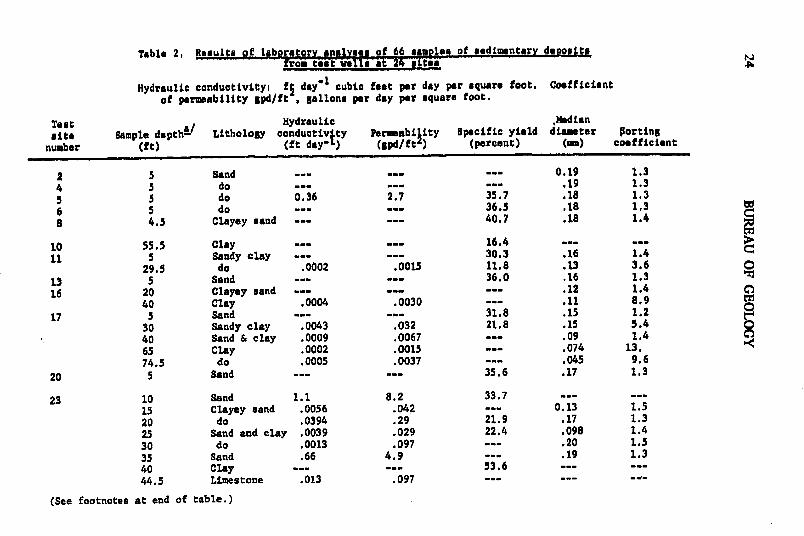
Table 2, Results of laboratory analyse pf 66 saamples of edinmentary dewosttfrom test weill at 24 sites 4
Hydraulic conductivityi ft day" cubic feet per day per square foot. Coefficientof permeability gpd/ft , gallons per day per square foot.
Test Hydraulic ,AMdian
site Sample depth-/ Lithology conductiv ty Permeability Specific yield diameter porting
number (ft) (ft day-L) (gpd/ftL) (percent) (i) coefficient
2 5 Sand -... . .. 0.19 1.3
4 5 do -. .- - .19 1.35 5 do 0.36 2.7 35.7 .18 1.3
6 5 do .... 36.5 .18 1.3
8 4.5 Clayey sand -.. 40.7 .18 1.4
10 55.5 Clay ... -. 16.4 .. -
11 5 Sandy clay -. .. 30.3 .16 1.4
29.5 do .0002 .0015 11.8 .13 3.6 0
13 5 Sand - -- 36.0 .16 1.3
16 20 Clayey sand -.... .12 1.4
40 Clay .0004 .0030 -- .11 8.9
17 5 Sand -- - 31.8 .15 1.2
30 Sandy clay .0043 .032 21.8 .15 5.440 Sand & clay .0009 .0067 -- .09 1.4
65 Clay .0002 .0015 -- .074 13.
74.5 do .0005 .0037 -- .045 9.6
20 5 Sand -- - 35.6 .17 1.3
23 10 Sand 1.1 8.2 33.7 --
15 Clayey sand .0056 .042 --- 0.13 1.5
20 do .0394 .29 21.9 .17 1.3
25 Sand and clay .0039 .029 22.4 .098 1.4
30 do .0013 .097 .- 20 1.5
35 Sand .66 4.9 -- .19 1.3
40 Clay .. -53.65 -
44.5 Limestone .013 .097 - - --
(See footnotes at end of table.)
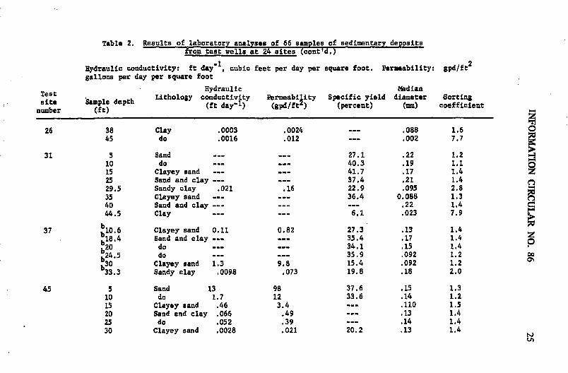
Table 2. Results of laboratory analyses of 66 samples of sedimentary depositsfrom test wells at 24 sites (cont'd.)
Hydraulic conductivity: ft day 1 , cubic feet per day per square foot. Permeability: gpd/ft2
gallons per day per square foot
Test Hydraulic Mediansite 'Sample depth Lithology conductivity Permeabi ity Specific yield diameter Sorting
te S e et (ft dayl1) (gpd/ft ) (percent) (mm) coefficientnumber (tt)
26 38 Clay .0003 .0024 --- .088 1.6 045 do .0016 .012 -- .002 7.7
31 5 Sand - --- 27.1 .22 1.210 do .- -- 40.3 .19 1.1 015 Clayey sand - -- 41.7 .17 1.4 225 Sand and clay -- -- 37.4 .21 1.4 029.5 Sandy clay .021 .16 22.9 .095 2.835 Clayey sand . --- 36.4 0.088 1.340 Sand and clay ----- --- .22 1.444.5 Clay ..... 6.1 .023 7.9
37 10.6 Clayey sand 0.11 0.82 27.3 .13 1.418.4 Sand and clay -- - 35.4 .17 1.4 Z
b20 do -- -- 34.1 .15 1.424.5 do -- -- 35.9 .092 1.2 oo
b30 Clayey sand 1.3 9.8 15.4 .092 1.2 033.3 Sandy clay .0098 .073 19.8 .18 2.0
45 5 Sand 13 98 37.6 .15 1.310 do 1.7 12 33.6 .14 1.215 Clayey sand .46 3.4 -- .110 1.520 Sand and clay .066 .49 -- .13 1.425 do .052 .39 -- .14 1.430 Clayey sand .0028 .021 20.2 .13 1.4
t/i
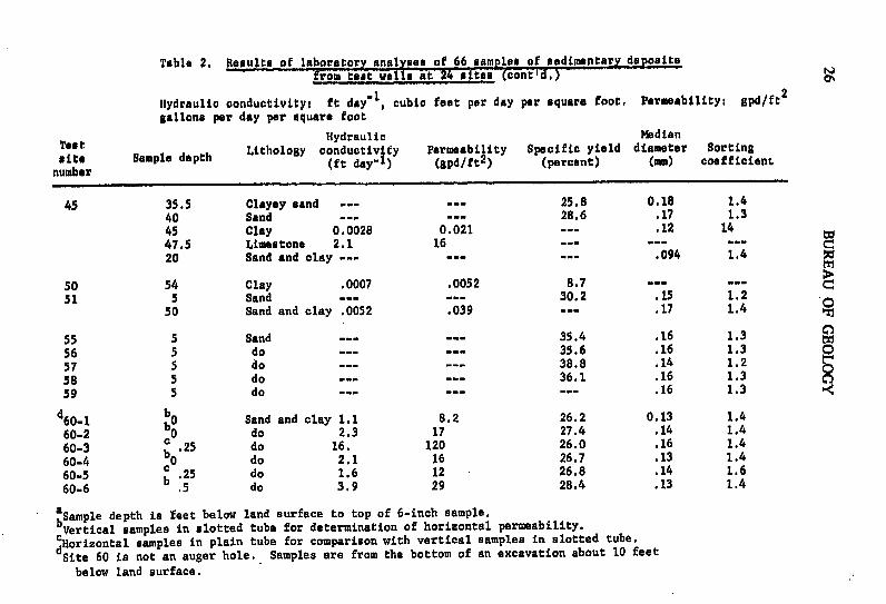
Table 2, Results of laboratory analyses of 66 samples of sedimentary depositsfrom test wvell at 24 sites (cont'i,)
Hydraulic conductivity: ft day" , cubic feet per day per square foot, Permeability; gpd/ft2
gallons per day per square foot
Test Hydraulic Mediante e depth Lithology conductivity Permeability Specific yield diameter Sorting
ite Sample depth (ft day ) (gpd/ft2) (percent) (mm) coefficientnumber
45 35.5 Clayey sand ...- . 25.8 0.18 1.4
40 Sand ..... 28.6 .17 1.3
45 Clay 0.0028 0.021 .. .12 14
47.5 Limestone 2.1 16 - .-20 Sand and clay -... ... .094 1.4
50 54 Clay .0007 .0052 8.7 .. ---51 5 Sand ..... 30.2 .15 1.2
50 Sand and clay .0052 .039 .. .17 1.4
55 5 Sand ... 35.4 .16 1.3
56 5 do - - 35.6 .16 1.3
57 5 do ... --- 38.8 .14 1.2
58 5 do .. ... 36.1 .16 1.3
59 5 do ...... . .16 1.3
60-1 bO Sand and clay 1.1 8.2 26.2 0.13 1.4
60-2 O do 2.3 17 27.4 .14 1.4
60-3 c .25 do 16. 120 26.0 .16 1.4
60-4 b0 do 2.1 16 26.7 .13 1.4
60-5 c 25 do 1.6 12 26.8 .14 1.660-6 b .5 do 3.9 29 28.4 .13 1.4
aSample depth is feet below land surface to top of 6-inch sample.
Vertical samples in slotted tube for determination of horizontal permeability.cHorizontal samples in plain tube for comparison with vertical samples in slotted tube.
Site 60 is not an auger hole. Samples are from the bottom of an excavation about 10 feet
below land surface.

INFORMATION CIRCULAR NO. 86 27
Table 3. Clay-mineral identification for selected samples
Sample depthTest site (feet) Description
Differential Thermal Analysis
5 35 Illite. Mixed-layered clay (illite andmontmorillonite) small amount; quartz,small amount; organic material, smallamount; CaCO3, none.
17 65 Illite, Mixed-layer clay (illite andmontmorillonite) small amount; quartz,large amount; organic material, moderateamount; CaCO3 none.
23 40 Illite, small amount; organic material,large amount; CaCO3, very large amount,75 percent.
26 38 Mainly mixed-layered clays, composed ofillite and montmorillonite. Illitepredominant.
26 45 Mainly mixed-layered clays composedof illite and montmorillonite. Illitepredominant.
31 44.5 Illite. Mixed-layered clay (illite andmontmorillonite), small amount; quartz,small amount; organic material, smallamount; CaCO3, none.
50 20 Illite. Quartz, small amount; organic,large amount;CQaCO3, none.
50 54 Illite. Mixed-layered clay (illite andmontmorillonite), small amount; quartz,fair amount; organic material, fairamount; CaCO3, none.

28 BUREAU OF GEOLOGY
Table 3. Clay-mineral identification of selected samples (cont.)
Sample depthTest site (feet) Description
X-ray Diffraction
37 36 Sample contains about 35 percent quartz,2-3 percent feldspar, and the remainderclay minerals. The clay mineral is mont-morillonite with a small amount of illitemixed layering. The basal spacing isindicative of Ca-montmorillonite.
46 30 Sample contains about 30 percent quartzand the remainder clay minerals. Clayminerals consist primarily of a random-mixed-layer illite-montmorillonite inwhich the montmorillonite layers are themost abundant. The peaks are poorly de-fined, but d spacings greater than 150indicate the presence of some regularmixed layering. On heating to 3000 C,the clay mineral collapses to 10.4°,which indicates some interlayering.
INFORMATION CIRCULAR NO. 86 29
TABLE 4Logs showing lithology, gamma radiation, and generalized
geohydrology of surficial deposits at sites testedin northwest Hillsborough County
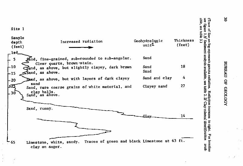
Site 1
Sampledepth Increased radiation Geohydrol9gic Thickness ( 0
(feet) _ unitE (feet) -
lsd
5 -nd, fine-grained, sub-rounded to sub-angular. Sand
Clear quartz, brown-stain.10 and, as above, but slightly clayey, dark brown Sand 18
-15 and, as above. Sand o
20 d, as above, but with layers of dark clayey Sand and clay 4sand 0
Sand, rare coarse grains of white material, and Clayey sand 27
30 clay balls.Sand, as above. D 0
0
Sand, runny. 5'
142
65 Limestone, white, sandy. Traces of green and black Limestone at 63 ft. 0
clay on auger. S S.0

Site 2
Sample Geohydrologic Thicknessdýl) unit (feet)
-5 a/Sand, very fine-grained, well rounded clearquartz. .
10 Sand, as above but slightly silty with black Sand 17 orootlets.
S Sand, as at 5 ft.Sand, as above but with broken layers of dense
20 black-brown clay.Sand and clay 13 0
-25 Sand, with layers of clay, as above.
-30 Sand, as at 5 ft but runny; clayey.
-35 Sand, as above Clayey sand 30
45 Sand, very fine to medium-grained, with brownclay.
00
55 Sand, light brown, clayey.
60 Sand and clay layers, light brown. Sand and clay 5
-65 Clay, sandy, with limestone chips. Sandy clay 368 Limestone. Limestone at 68 ft.

Site 3
Sampledepth Geohydrologic Thickness
(feet) Increased radiation unit (feet)
-ladldi -su rounded. Clear Sand 15
airT ratenegu wiaaw wn by slight silt content.-0 aF aove e.
10 d, as above but with some clay.
_15 Sand ey.
20 Sand, cla as above but with streaks of light Clayey sand 15tan clay 0
.25 Sand, clay massive, runny.
-30 Sand, r a ove. Slightly more clay. Sand 5
-0 Sand, clayey as above. Clayey sand 5
-45 Sand.and clay and shell Sand
-50 Clay, light green, sandy. -e"
55 Sand, slightly clayey, with clay ba Sandy clay 15
-60 Clay, light green, sandy.
5 Clay, li ht rers of dense black clay. Clay 2-67 Limesto e, gray, sandy, hard. Limestone at 67 ft.

Site 4
Sample Geohydrologic Thicknessdepth unit (feet)(feet)
lsd
5 a/Sand, very fine-grained, well-rounded clear quartz.Slightly clayey.
10 Sand, as above, but black from organic material. Sand 2015 Sand, as at 5 ft. but dark brown.
20 Sand, as above, but with streaks of clay. Sand and clay 525 Sand, brown, clayey.
S30 Sand, brown, clayey. Clayey sand 10 Z
35 Sand, as above, with clay streaks and chips of charcoal oto 5 mm.
40 Sand and clay, light brown with streaks of black clay. Sand and clay 10
45 Clay and sandy clay laminae. Dark brown with pieces of Clay 548 white chalky chert.
"50 Clay, green, plastic. Weathered limestone at 50 ft. Limestone at 50 ft.54 Limestone.

Site 5
Sample Geohydrologic Thicknessdepth Increased radiation unit (feet)(feet)
5 a/ and, very fine-grained, sub-angular clear quartzwith dark brown stain. Very slightly clayey.
-10 and, as above but with black stain. Sand 20
15 San s above.
-20 SanF, as above but with more clay.
25 Sand, c ey as above.
-30 Sand, cla •ea . Clayey sand 11- 30 Sand, cla ve.b/- 35 Cla, ..
Limestone at 35.5'. Clay 4.5-40 Limestone, white, sandy. Limestone at 35.5 ft.
• ,, , • i

Site 6
Sample Geohydrologic Thickenssdepth Increased radiation unit (feet)(feet)
S-lsd
5 Sand, brown, fine-grained, slightly silty, organic.
-1 Sand, as above. Sand 20
-15 and, as above with rootlets. 2-20 nd, tan, clayey.
Clayey sand 1225 San ey as above.
_30 Sand, clayey s above.-33 Sand, with clay stre Sand and clay 13
-38 Sand, as above with more clay. 040 Sand and clay, as above. oo
-45 Clay, sandy. Dark gray-black drusy chert. Sandy clay 10
-50 Clay, dark gray with yellow streaks, sandy.
55 Limestone, sandy. Weathered light gray and Limestone at 55 ft.cream. Fine drusy pyrite in small vugs.

Site 7
Sample Geohydrologic Thicknessdepth Increased radiation unit (feet)(feet)
Snd, dark brown, very fine-grained, silty. Sand 15-u10 and, as above but darker brown.
-15 Sand and clay laminae, light brown. o-20 nd and clay, as above but more clay. Sand 16
-25 Sand and c l a ove.
Sand and cia a ove.-3 Sand, ry ai d. wtll rounded, clear Sand 4_ 35 quarcz
-' Sand, as above.40 tnd and clay laminae, light gray. -- nr clay 10
45 Sand and clay. C1-y in 1 pEa-plastic, black
C47 land i c, shades of green with streaks of-53 white and. Contortions in laminae may be due Clay 8
to collapse. .Limestone, white, with brown chert. Limestone at 53 ft.
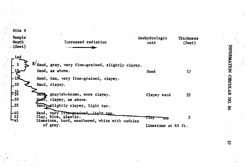
Site 8
Sample Geohydrologic Thicknessdepth Increased radiation unit (feet)(feet) Ab
1sd
5 aSand, gray, very fine-grained, slightly clayey.1 Sand, as above. Sand 17
Sand, tan, very fine-grained, clayey.
20 Sand, clayey.
grayish-brown, more clayey. Clayey sand 2530 , clayey, as above.
-35 San lightly clayey, light tan. oo-40 Sand, very42 Clay, blue, plastic. 345 Limestone, hard, weathered, white with nodules
of gray. Limestone at 45 ft.

00
Site 9
Sample Geohydrologic Thicknessdepth Increased radiation unit (feet)(feet)
d5 Sand very fine-grained, rounded to sub-rounded Sand 28
clear quartz. t1 Sand, light brown, fine-grained to silty, poorly
sorted, slightly clayey. Occasional darkgrains.
S20 Sand and clay, layers, clean white sand, brown 0clay. 1o
30 Sand, c aye Clayey sand 2Sandy clay 5
- 35 Clay, sand ough, grayish brown.
- 40 San ite, fine-grained to silty. Poorly Sand 5sorte , unded to sub-angular.
Sandy clay 10
- 59 Clay, black. Clay 10S60 Limesto Ce. Limestone ft- E

Site 10
Sample Geohydrologic Thicknessdepth Increased radiation unit (feet)(feet)
-lsd
S5 a, very fine-grained, brown. 0
S10 Sa as above, dark brown Sand 15
S15 Sand, as ove.- 17 Sand a y dark brown. Clay nodules and thin Sand and clay 10
0 s of dense dark clay.San cay, as above.
25 Sand, c light brown. Sandy clay 3Clay, sand . n-Sand, sy -. nd.Sand and clay 530 Sand, very fine. ned. Occasional clay balls. Sand and clay 5
35 Sand, very ine-grained, tan. Sand 7
40 Sand, clayey very runny. Clayey sand 6 0
45 Sand, less clay, rnn . Sandy clay 10
50 Clay, variegated yellow-gray, sandy.
-55 Malay gray with stringers of green, plastic,chips of limestone at base. Clay 6
60 Clay, as above but with more coarse pieces of62 limestone.
Limestone, gray. Limestone at 62 ft.
UJ

Site 11
Sample Geohydrologic. Thicknessdepth Increased radiation unit (feet)(feet) --
Isd
- 5 i-S hclayey, grayish-tan, tough, with rootlets >a s of marl. Sandy clay 8 C
10 Sand, very - rained, rounded to sub-rounded, 0some clay, lig tan, occasional dark grains. '
15 Sand, as above but w ightly more clay, gray.
20 Sand, very fine-grained, sub. unded clear Clayey sand 20quartz. Very slightly claye
25 Sand, as above but with more gr.ay c
30 a/Clay, light green, , ugh plastic. Sandy clay 12
35 Sand, light gray, very ine-grained, rounded tosub-rounded, sa8 y clayey.
-40 4 Limestone, whi e, sandy, crumbly. Limestone at 40 ft.'44

Site 12
Sample Geohydrologic Thicknessdepth Increased radiation unit (feet)(feet)
lsd0
5 , light gray, clayey. Clayey sand 6
10T Sand, very fine-grained, rounded to sub-rounded, Sand 14clear quartz, slightly clayey.
15 Sand, as above but no clay.
S20 d clay laminae.- 25 Sardn ay, as above but with more clay. Sand and clay 6
30 ay, greenish-brown, sandy.35 S d, light brown, clayey. Clayey sand 19 Z
40 Sand, claye ,r
45 Sand, clay47 Clay, green, sandy.- Clay 6
S55 Limestone, gray, sandy, with dark layers of Limestone at 51 ft.sand and siliceous cement.

Site 13
Sample Geohydrologic Thicknessdepth Increased radiation unit (feet)
(feet)
S5 -Sand, brown, very fine-grained. Sand 16
10 Sand, as above but darker brown, with organic silt.12 Sd, as above.
. 94 a• .5 ft but slightly silty. Clay 2Clay 2 0
20 San , ht brown, very fine-grained, slightly silty. Sand 7
.30 Clay, light gray, s Sandy clay 7-33 Sand, gray, ainae. Sand and clay 2
36 Sand, light br ery fine-grained, silty. Sand 340 Sand, runny. Clayey sand 1045 ery soft. Tools droppe ne. C 3
50 Limestone, A 3, ufi, dense. Limestone at 50 ft.
-59 Limestone, white, medium hard, amorphous.

-Site 14
Sample Geohydrologic Thicknessdepth Increased radiation unit (feet)(feet)
ls8 p
S5 Sand, very fine-grained, sub-rounded to sub-angularclear quartz brown. Slightly clayey.
10 d, as above but with black stain from silt.
-15 Sa , as above. Sand 16 Z
-20 fSand, as above but clayey, with streaks of clean white Clayey sand 5sand. S
25 nd, white, very fine-grained, rounded clear quartz. Sand 6 C
-30 Sand an , laminae light brown. Sand and clay 5
35 Clay dy. Sandy clay 5 240 S•t very fine-grained, sub-rounded, runny. Sand 10
47 Clay, gray, soupy, " d shells to 1 mm and chert, Clay 7grayish-white, to 3 cm.
-55 Clay, sandy, soupy as above. -- clay 6
60 Limestone, gray, sandy, hard. Limestone at 60 ft.

Site 15
Sample Geohydrologic Thickness
depth Increased radiation unit (feet)
(feet)
-ls
-5 , dark brown, very fine-grained, with someorganic material.
-10 Sand, chocolate brown, as above. Sand 17
-15 Sand, as above but with less organic material.
-20 d white, clayey.25 Clay, gray, sandy (very fine-grained). Sandy clay 15
27-30 , hite-gray, sandy (very fine-grained). Clayey sand 5
.35 t, . r fine-grained, clayey. Sandy clay 3
4042 Clay, very soft; sampler d from 40 to 42'. Clay 545 Limestone, light gray, very hard. Limestone at 45 ft.

Site 16
Sample Geohydrologic Thicknessdepth Increased radiation unit (feet)(feet)
Isd- -Sand light brown, very fine-grained sub-rounded
clear quartz, slightly clayey.- Sand, as above but dark brown. Sand 17
15 Sand, as. above but with mottles of slightly clayier
40 a/Clay brown and gray layers, plastic with so-sand_- 5a sand chert.
- 45 Limestone, white-gray, den some sand, crystals of Limestone at 44 ft.
S47 calcite.Limestone.
vi

Site 17
Sample Geohydrologic Thicknessdepth Increased radiation unit (feet)(feet) -
ad
-5 -Sand, very fine-grained, sub-rounded to rounded, clearquartz, with slight black silt.
-10 nd, as above, but with slight brown silt.
-15 , as above, runny. Sand 15
-20 as at 5 ft but with slightly more clay and layersr-e ay sandy clay.
S25 d, light tan, very fine-grained, sub-rounded, runny,a/ 3 0tt some claY.
S30 Cl rown, san y (very fine-grained, sub-rounded). Clayey sand 2535 Sand light tan, very fine-grained, sub-rounded, runny
40 a/Sand, as above, w n n clay. Clay 3 0S45 Clay, black, plastic, w an y c ay. Sand and clay 20
50 Clay, black, with drusyy p and black fibrous material.Sandy.
- 55 Clay, dark y, sandy, with layers of pure black clay. Sandy clay 460 Sand, gray, v - rained, sub-rounded, slightly
b/ clayey. Very soft; sampler sa Clay 465 - Clay, green, plastic, some sand. Sandy clay 5
75 Clay, green and black layers and mottles. Plastic, sandy ayS 480 Limestone, white-gray, dense, hard. 4=Z Limestone at 80 ft.

Site 18
Sample Geohydrologic Thicknessdepth Increased radiation unit (feet)(feet)
i-sd
5 nd, light brown, very fine-grained, sub-angular tosub-rounded, and dark brown clay. ZS10 very fine-grained, sub-rounded, with black silt. Sand 18
15 Sand, 'ite, very fine and occasional medium-grained.Sub-roun to rounded.
- 20 Sand, as above t with greenish-brown clay.
-25 Clay, greenish-brown, sa Clayey sand 10Sandy clay 5- 30 Sand, white, very fine-gra d. Sub-rounded, clear Claey sad 5 0
quartz with gray clay. Clayey-35 Clay, gray, with layers of sg , e- Sandy clay 4
-40 ,Sand, gray, clayey.
S45 Limestone, white and light tan, sandy, dense, hard. Limes.tone at 42 ft.
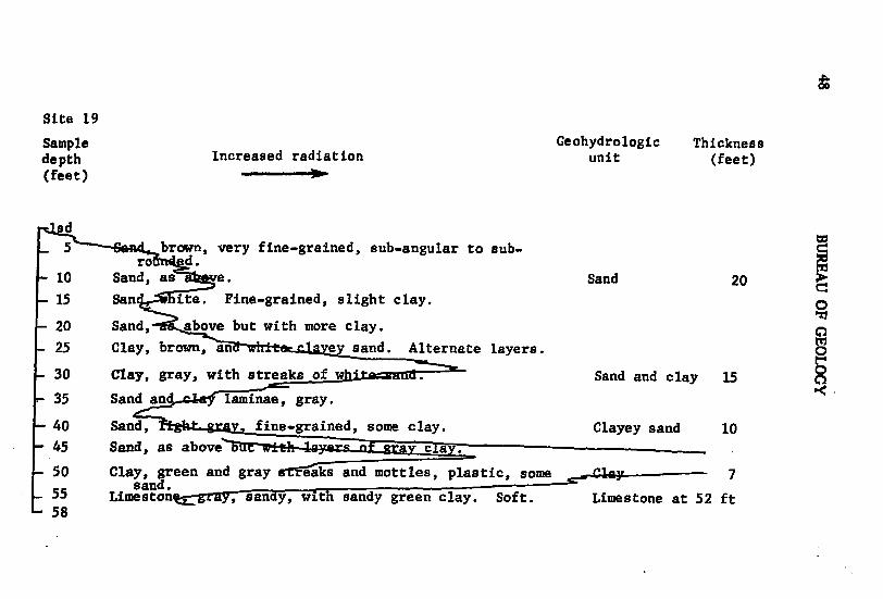
Site 19
Sample Geohydrologic Thicknessdepth Increased radiation unit (feet)(feet)
sd5 brown, very fine-grained, sub-angular to sub-
ro d.10 Sand, as e. Sand 20 I
-15 San ite. Fine-grained, slight clay.
20 Sand, above but with more clay.
S25 Clay, brown, an ey sand. Alternate layers.
30 Clay, gray, with streaks of whr.d- Sand and clay 15
-35 Sand an laminae, gray.
-40 Sand, ra fine-grained, some clay. Clayey sand 1045 Sand, as above u c a.
50 Clay, green and gray etaks and mottles, plastic, some n _ay- 7sand.
55 Limeston , sa y, with sandy green clay. Soft. Limestone at 52 ft58

Site 20
Sample Geohydrologic Thicknessdepth Increased radiation unit (feet)(feet)
5 - nd, tan, very fine-grained. Occasional mottlingsf chocolate brown clay.
1015 and 1715 0
-20 Sand, tan, v fine-grained, with brown clay. y sdClayey sand 18
2530 Sand, as ye, but with slightly less clay.35 Sand, tan, very ne"gra n
40 Limestone, light ay with oatterd and. ULIU LonLe .. 38 ft.
45 Clay, greenish-gray, ve r sandy. o
- 50 Limestone54

0
Site 21
Sample Geohydrologic Thicknessdepth Increased radiation unit (feet)(feet)
lad-5 San , n, very fine-grained, sub-rounded to rounded.
10 nd, as above, but with slight gray clay. Sand 17
15 nd white, very fine-grained, sub-rounded to rounded._20 Sand, as above with some gray clay.
25 Clayey sand 19
-30 Sand, as a nd grayish-tan clay layers.
-35 Sandlight gra , , rained, s ht Clay 3clayey.
-40 Clay, light green, rw some sand and fine pyrite.
-45 Cla a ove, but with mottles of black clay. Clay (?) 17-50 Clay, as e. Very hard, dry, breaks into blocks.
55 Clay, as above, ot hard. Limestone at 56 ft.
-60 Limestone.

Site 22
Sample Geohydrologic Thickness,depth Increased radiation unit (feet)(feet
0d
S, brown, very fine-grained, sub-rounded to Sand 5rounded, ar quartz.
-10 Sand, as ab but with some clay gray with brownishmottlin • higher clay content
-15 Sand, as ve, but with less clay. Clayey sand 15-20 Sand and clay lgn1 e, brownish-gray.,25
-30 Sand and c as above but runny. Sand and clay 20 Z0
-40 Clay, greenish-gray, lae sying sand content. Clay 5
45 Limestone, ,~agWt y- iayersr r of sandy green clay. Limestone at 45 ft.-48
LA
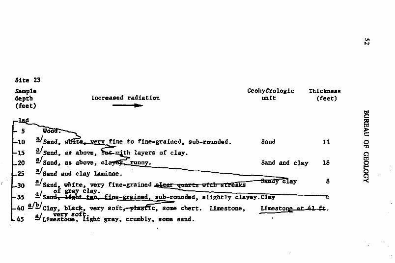
Site 23
Sample Geohydrologic Thicknessdepth Increased radiation unit (feet)(feet)--
-d5 >.
10 a-'Sand, w e s fine to fine-grained, sub-rounded. Sand 11 0
15 a-Sand, as above, -th layers of clay.
20 S/Sand, as above, cl runny. Sand and clay 18 0
25 a/Sand and clay laminae. o-30 a Sand, white, very fine-grained w c 8
a of gray clay.-35 -Sa "ne-grained, sub-rounded, slightly clayey.Clay 4
-40 a/Clay, black, very soft,-pfic, some chert. Limestone, Limestoe na . ft.a/ very soft.
-45 - Limestone, light gray, crumbly, some sand.

Site 24
Sample Geohydrologic Thicknessdepth Increased radiation unit (feet)(feet) g
'sd
S5 v-ery fine-grained, well-rounded, well sorted Sand 5 >clea tz.
-10 Sand, as ab , but with clay layers.
15 Sand and clay 15
-20 Sand, , with streaks of clean sand.
-25 Sand, li gray, clayey.
30 Sand, as above, but s more clayey. Clayey sand 20
00
-35
40 Clay, br ar ud ea with layers of sandy clay. Clay 2-45 Limestone, ray, sandy. Gastropod 1 cm across. Lis r _• t.
50 Limestone, gray, sandy, with chrii -53 Dark gray sandy clay at 50' wv h shards of chert.

Site 25
Sample Geohydrologic Thickness
depth Increased radiation unit (feet)
(feet)
1id .and, dark brown, fine-grained, silty, roots.S fine-grained, sub-rounded clear quartz. Slightly Sand 16
tan9 I as'aove, biu black >S n1 as ove, br pan from 6.5' to 12'.and, as above, but more indurated.
-15 Sa fine to very fine-grained, sub-rounded clearquartz.
-20 Sand, brown, c Clayey sand 9
-25 Sand, 1 rown, fine to-very fine-grained, sub-rounded Sand 5ar quartz. Runny.
-30 San layey. Clayey sand 5
35 Sand, tan, ined, sub-rounded clear quartz. Sand 7
44 Clay, green, Clay 345 Limestone, sad. Limestone at 45 ft.
49

Site 26
Sample Geohydrologic Thicknessdepth unit (feet)(feet)lsd Sand, fine-grained, sub-rounded clear quartz
slightly silty (black) with many rootlets and Sand 105 husSanu, as above but more silt (brown). No humus.-10 Sand, as above but with chips of brown,clayey,
indurated sand15 Sand, asat 1ft.but with layers and mottles of Sand and clay 1520 brown clayey sand.
Sand and clay laminae.25 Sand, fine to very fine-grained, sub-rounded Clayey sand 9
clear quartz with matrix of brown clay.
33 Clay, sandy, grades downward into dense greenclay at 34'.
38 a/ b/ Clay, greenish-gray, dense. With streaks of Clay 14sand.
-45 a! b/ Clay, as above.48 Limestone, hard. Limestone at 48 ft.'51
Lfl

Site 27
Sample Geohydrologic Thickness
depth Increased radiation unit (feet)
(feet) .lasd
Sand, clayey. Clayey sand 20
-15 nd, brown, clayey.
-20 Sand, to very fine-grained, sub-rounded clear quartz.Wit yers of clayey sand.
25 Sand, ey as above, clay content increases downward. Sand and clay 24
45 Clay, green{-h t_, eaenaz awdy, with chert fragments. Clay 448 Limestone, hard. Limestone at 48 ft.
-53
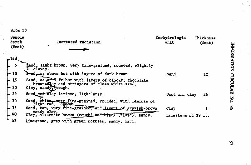
Site 28
Sample Geohydrologic Thicknessdepth Increased radiation unit (feet)(feet) __
,lsd
S55 snd, light brown, very fine-grained, rounded, slightlyclayey. z
-10 s above but with layers of dark brown. Sand 12
-15 Sand, as 5 ft but with layers of blocky, chocolatebrown ay and stringers of clean white sand.
- 20 Clay, sandy, ough.-25 Sand ay laminae, light gray. Sand and clay 26
- 30 Sand fine-grained, rounded, with laminae of 0light tan. an 0
35 Sand, tan, very fine-graine f ayish-brown Clay Isandy clay. - -
-40 Clay, alternate brown (tou ha l b i uid), sandy. Limestone at 39 ft.43 Limestone, gray with green mottles, sandy, hard.
-.1

Site 29
Sample Geohydrologic Thicknessdepth Increased radiation unit (feet)(feet)
ad
5 d, very fine to fine-grained, sub-rounded clear quartz Sand 16a and tan clay.
10 Snd, white, very fine to fine-grained, sub-rounded clear 0
30 Sand and clay laminae.--- Sand and clay 17
-35 Sand, and gray clay. Clay s 3
-39 Limestone, light gray, sandy, very hard. Limestone at 39 ft.
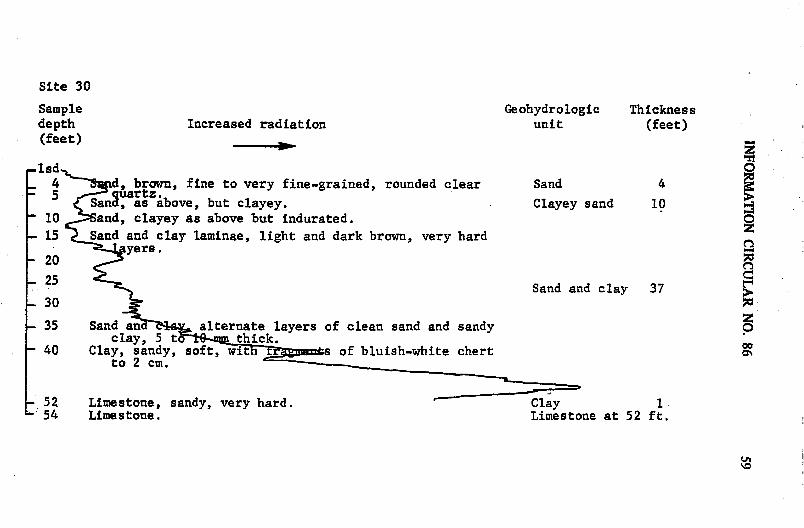
Site 30
Sample Geohydrologic Thicknessdepth Increased radiation unit (feet)(feet)
1lsd 04 d, brown, fine to very fine-grained, rounded clear Sand 45 auartz.
S and, as above, but clayey. Clayey sand 1010 and, clayey as above but indurated.
-15 Sand and clay laminae, light and dark brown, very hard2yers.-20
325 Sand and clay 3730
35 Sand an alternate layers of clean sand and sandy 0clay, 5 t thick. "
40 Clay, sandy, soft, wit of bluish-white chertto 2 cm.
52 Limestone, sandy, very hard. Clay 154 Limestone. Limestone at 52 ft.

Site 31
Sample Geohydrologic Thicknessdepth Increased radiation unit (feet)(feet)
aw- Sand, very fine-grained, sub-angular to sub-rounded Sand 15a I/ clear quartz.
-1 Sand, as above, but slightly clayey, runny.
15 - as above, but more clayey.
20 Sand, clayey as , very runny.
S25 a/Sand and rown,a/ Sand and clay 27 0-30 -/Clay, light brown, tough.
- 35 a/Sand, clayey.
40 -/Sand adclay laminae.
45 -a-Clay, green, plastic san ack clay, soft plastic Clay 5with chet
50 Limestone, soft, sandy, with mollusc shell. LiTstone at 47 ft.
-59 Limestone.

Site 32
Sample Geohydrologic Thicknessdepth Increased radiation unit (feet)(feet) M-
01 d
S Sand, light tan, very fine-grained, occasional medium-grained. Well rounded clear quartz, slightly clayey.
-Sand, as above, but brown. Sand 15
15 nd, as at 5' but with streaks of brown sandy clay.
20Sand and clay 21
-25 Clay, tan, san ayers.- 30 Sand, ey as at 15'
S35 Cla) y hg plastic, sandy, wit streaks of Sand.- 39 Clay, green grades downward into limestone. Clay 4 M-40 Li n ight gray, hand Fsure tilled with calcite. Limestone at 40 ft.
-48 Limestone, soft, slightly sandy, clay streaks.
oa

Site 33
Sample Geohydrologic Thicknessdepth Increased radiation unit (feet)(feet)
-1
- and, tan, very fine-grained, well-rounded, clear quartz. Sand 10Slightly silty.
1 Sand, dark brown, clayey.0
- 15 Sand, as at 5' but with streaks of dark brown clay.- 20 ~C• ark brownish-gray, dense, plastic. Sand and clay 21 t
25 S some clay. t0
-30 Saudmayv fine to medium g rl an, m , om-e-eay.----_35 Sand clayey, ru Clay 538 Limestone, light gray t.iuff, very tnin-bedded, occasional Limestone at 36 ft.41 sand grains.4- Cavity (?J, half foot of very soft drilling.-"
- 48 Limestone.

Site 34
Sample Geohydrologic Thicknessdepth Increased radiation unit (feet)(feet) . -4
.I and, tan, very fine to fine-grained.
5- Sand 20
10 a , as above, but slightly clayey.-15 Sal, as above, but with very fine-grained clay balls,
k brown.-20 Sand, a above, but with more clay balls. Sand and clay 15
Sand and ay laminae.
30 Sand, very slightly clayey.
-35 Clay, 1-a6, 1- 2 *. U I Ers of soft non- Clay 5calcareous hite material. Grades aMdnward into sandy o
40 claywith char_._ _
Clay' dark gray, plastic, i .
Limestone at 50 ft.S50 Clay, green, plasti y sandy.50 ft.S50. Limestone, light gray, sa
-55 Limestone, as above.
-62 Limestone.

Site 35
Sample Geohydrologic Thicknessdepth Increased radiation unit (feet)(feet)
Sand, tan, very fine-grained, well-rounded clear quartz.2 Slightly silty.
6 Sand, as above, but with organic mottles.7.5 Sand, light brown with streaks of iron-stained cemented Sand 199 /> grains. Very fine-grained, well-rounded, slightly silty.10. Sand, as above, but with no streaks.11 Sand, as above, but with clay mottles.13 . Sand, as above, but with streaks of organic material.14.5 Sand, very fine-grainea, with thin clay streaks.15 Sand, as above.17 Sand, very fine-grained, clayey, runny.
23 Clay y, sandy, plastic.24 Sa clayey; streaks of varying clay content.26 Sand, layey, massive. Clayey sand 18
29.5 San clayey, more clay than above.31.5 Sand, ey, with layers of sandy clay.32 Sand, v fine-grained, slightly clayey, soupy.
S37 Clay, green-gray with occasional play of pyrTC•'-t1 -38 CSandy plastic vugs of drusy, white kaolinite (?)
Clay, alternate sreaKs of green and brown, plastic, slick,40 some sand.Clay, softer than above, slightly more sand. Clay 5

Site 35 continued
Sample Geohydrologic Thicknessdepth Increased radiation unit (feet)(feet)40 Clay, dark.gray, much chert in plates and angular pieces
to 2 cm. Black with gray rime. Limestone at 42 ft.42 Limestone, light gray, very hard.
53 Limestone, soft, with layers of plastic green clay.
Sz0000
69 Limestone with clay streaks; hard and soft layers.

Site 36
Sample Geohydrologic Thicknessdepth Increased radiation unit (feet)(feet) _
isd
5 Organic soil; swamp.Clayey sand 13
-113 Sand, brown, very fine-grained. Sand 11
S4 Clay, sandy, massive, gray. Sandy clay 10Clay, more sandy than above. 0
- 3 Sand, clayey. Clayey sand 4
'-38 Clay, dark gray, tty with grains and plates of chert. Clay 4.5
- 42.5 Limeston•,lh gray, v-ry hard.Limestone at 42.5 ft.
S48 Clay. -
S55 Li tone.
67 Limestone.

Site 37
Sample,depth Geohydrologic Thickness(feet) Increased radiation unit (feet)
SIsdS1.5 . nd, very fine to fine-grained, sub-angular clear quartz.
Slight black silt. Z
-5 06.5 Sa as above, but with slight pinkish tinge. Sand 11
Sa/an ,a a above, but with very slight clay.11.1 Sand, clayey with mottles of clean sand. Clayey sand 112 Sand, very fine to fine-grained sub-angular, with laminae 0
of sandy clay and clayey san.
- 20 Sand and clay 1322 nd and clay, as above but with more clay.
S25.5 Sand, clayey, very runny. Clayey sand 9
30 - Sand, clayey.
.3 -Clay, sandy.8 ay, brown, sandy, Clay 7+
S Clay, green, plastic.L 36.5 -/Clay. C--

Site 38
Sample Geohydrologic Thicknessdepth Increased radiation unit (feet)(feet) .g
ad
Sand. very fine-grained. well rounded clear quartz.
- 10 Sand, as above, but with black silt; indurated.-15 Sand, as above, but slightly less indurated. Sand 35
- Sand, dark brown, slightly indurated, silty.0
30 dýao, very fine-grained, occasional medium-grained,iv clayey, runny.35 Sand, runny.
-40 Sand, gray, clayey. Sandy clay 13- 45 Clay: nd.
S50 Clay, black, p ti, dy.
55 Clay, black, plastic, wit ert grains and pieces to 1 cm. Clay 17Streaks of sand ayttci-.60 Clay, greenish-blac pastic, sandy, very soft.
Limestone at 65 ft.
S74 Limestone.,

Site 39
Sample Geohydrologic Thicknessdepth Increased radiation unit (feet)(feet)
s- d
- 5 Sand, light gray, very fine-grained, well rounded.
10 Sand', as above, but light brown.
1- Sand, as at 5 ft., but yellow-brown.Sand 20
-20 Sand, as at ut with chunks of gray sandy clay.-25 Sand bove, but with sand balls cemented by black, Clayey sand 15
& cement.-30 Sand, as a5 ft. runny.
-35 Sand, medium-grained clear quart ad Y ady c . S l00
-40 Clay, sandy, dense. --
.45 Limestone, grayisew , dense, sandy. Limestone at 43 ft.
51 Limestone.
0%
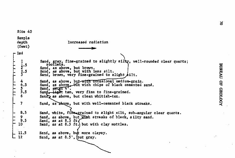
Site 40
Sampledepth Increased radiation(feet)
led
1 Sand, gray, fine-grained to slightly sil , well-rounded clear quartz;1.5 rootlets.
2 Sand, as above., but brown.2.5 Sand, as above, but with less silt.S3 Sand, brown, very fine-grained to slight ilt.
4 Sand, as above, bu asional medium-grain.-4.5 Sand, as above ut with chips of black cemented sand.- 5 Sand, .5.5 San tan, very fine to fine-grained.6 San as above, but clean whitish-tan.
7 Sand, as ve, but with well-cemented black streaks.
8.5 Sand, white, fi rained to slight silt, sub-angular clear quartz.9 Sand, as above but h streaks of black, silty sand.9.5 Sand, as at 8.5 ft
10 Sand, as at 8.5 ft. but with clay mottles.
11.5 Sand, as above, bu more clayey.S12 Sand, as at 8.5', but gray.

Site 40 continued
Sampledepth Increased radiation(feet) -
13.5 Sand, clayey with layers o lack and brown clayey sand.14 Sand, fine-grained to slight sub-angular clear quartz.
- 15 Sand, as above, but gray. 0
-16 Sand, clayey with mottles of black clayey sand.
-17.5 Sand, dark gray, clayey,
18.5 Sand, clayey. ZS19 Sand and clayey .s -
20 Sand , 00
20 Sand, lack, clayey.

Site 40 continued
Sample Increased radiationdepth(feet)
29.5 Sand, gray, sub-angular clear quartz with mottles of black c ayey sand.
-33 Sand, clean white with dense brown clay layers. Root es.

Site 40 continued
Sampledepth Increased radiation(feet)
-39.5 Clay, black, plastic, sandy, with bits of organic material (Charcoal?)-40 Sand, clean white quartz, and black, plastic, sandy clay in layers.-40.5 Clay, black, blocky, plastic, with occasional clean sand grain.
4 Peat, fibrous brown roots and organic material.
43 Sand, fine-grained to slightly clayey, sub-angular clear quartz, and black clay.
-44 Clay, black, and fibrous organic material. Z
-46 Clay, sandy, organic.
-48.5 Clay, black, blocky, organic material.
-50.5
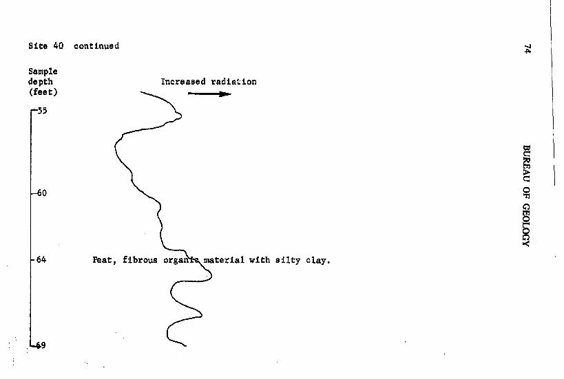
Site 40 continued
Sampledepth Increased radiation(feet)
-55
-0
-64 Peat, fibrous organ material with silty clay.
49

Site 40 continued
Sampledepth Increased radiation(feet)
-70
0
-75
0*
00-S-80
85

Site 40 continued--4
Sampledepth Increased radiation(feet)
85
-90
o,
-95
End ga a log at 98'.100107 Sand,! black, silty, with organic material.
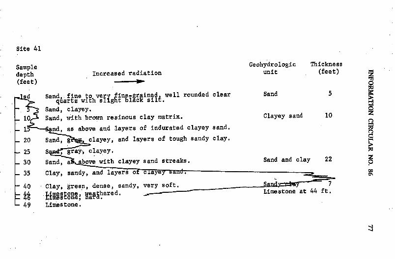
Site 41
Sample Geohydrologic Thickness
depth Increased radiation unit (feet)
(feet) --
sd Sand, fine to very fine-gr ined well rounded clear Sand 5qquartz with slight black sili.
- Sand, clayey.S10 Sand, with brown resinous clay matrix. Clayey sand 10
Snd, as above and layers of indurated clayey sand.
20 Sand, g clayey, and layers of tough sandy clay.
25 S , gray clayey.
S30 Sand, a bove with clayey sand streaks. Sand and clay 22
S35 Clay, sandy, and layers oF cayey and.
- 40 Clay, green, dense, sandy, very soft. San= 7
- 4 Limestone weathered. L-- - Limestone at 44 ft.4 Limestone. ar.
- 49 Limestone.

54
Site 42
Sample Geohydrologic Thicknessdepth Increased radiation unit (feet)(feet) -
Sand, dark brown stain, fine-grained sub-rounded to Sand 3S4> sub-angular clear quartz.
d, as above, but clayey. Clayey sand 110 Sand, 2' but clean white. Sand 13
15 Sand, runny.
- 20 Sand, with gray clay and streaks of dark gray 5 0- 23 Limestone, weathered, mottled with green clay. e-m .a nat 22 ft.-25 Limestone, very hard siliceous layers banded with weathered,
29 soft layers of white limestone. One well-rounded pebble9 of gray, pitted phosphate.

Site 43
Sample Geohydrologic Thicknessdepth Increased radiation unit (feet)(feet)
5 a- fine-grained, sub-rounded clear quartz.
10 Sand, as e, but with slight brown clay. 01 Sand 15
-15 Sand .-rne-grained to silt, poorly sorted, rounded tos b-roun ed, with layers of brown clayey sand.
-20 Sand, bove, but with less clay.
-25 Clay, gray s sandy, tough. Sand and clay 19
-30 Sand, clayey.
- 35 Clay. -- G ay 340 Clay, green, sandy, tou a .45 0
- 47 Clay, , but with no chert.: Sandy clay 38 oa
-55 Clay, sandy, and with light gree clay layers.
S65 Clay, as above, but wi ite chert.
- 5 Limestone, grayish-white, sandy. Limestone at 75 ft.

Site 4400
Sample Geohydrologic Thicknessdepth Increased radiation unit (feet)(feet)
-lsd-1 Sand, gray, very fine-grained, rounded to sub-
rounded clear quartz with slight black silt.- 3 Sand, light yellowish-brown. Sand 9- 5 Sand, dark brwn very fine-grained, rounded to
Sub-rouded clpar quartz slightly clayey.- A n , as above, but more clayey.- 7.5 San as at 5 ft. but with very slight clay.9 Sand, brown, very fine-grained, round to
sub-roun clear quartz with some clay.-10.5 Sand, more yey than above. Rootlets.-12 Sand, ce te, and layers of light brown, Clayey sand 11
snc clay cl- 13.5 S•an ght 4an, as at 9' but with less clay.-15 and, clayey, runny. 0
16.5 Sand, clayey.
-18.5 S d', clayey, with layers of sandy clay.
20 San d clay laminae.
- 23 Sand, white, very -rained, round to sub-rounded_ 2,. clear quartz slightly cS24,5 Sand and clay laminae, as at 20S a c
25.5 Clay, greenish-gray sandy. Sand and clay 13S27 Sand white, with yellow-brown reaks, slightly
28.5 Sand,a ligt brown, with some clay and yers of clayey30 San above but with more clay.30 San , 16 above but with more clay.

Site 44 continued
Sample Geohydrologic Thicknessdepth Increased radiation unit (feet)(feet)
30
-32 Sand, white, very fine-grained, slightly clayey.33.5 Clay, dark gray, dense, some sand.
-35 Clay, black, slightly sandy.Cl=a 7
-39.5 Cl ar gray. 0-41 d, white, very fine-grained, round to sub-rounded,
ghtly clayey, with layers of dark-gray clay. Sand and clay 5
44 Sand, white, and black clay in layers.-45.5 Clay, black, sandy. z-47 Clay, black dense, with str ks of clean white snad
and yellow-brown rootlets. oo48.5 Clay, black, with more whi sand and black woody o\material, and rare pl es of chert.
Sandy clay 10
55.5 Clay, blac and sand in laminations.
001-
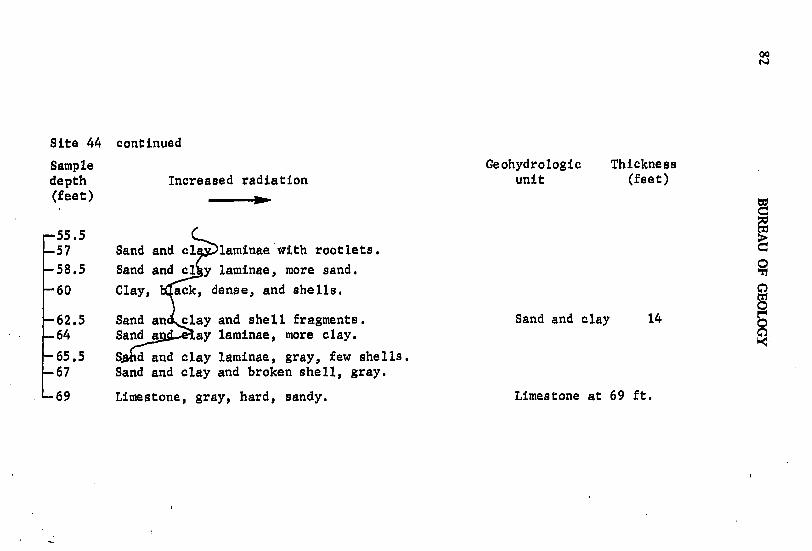
00
Site 44 continued
Sample Geohydrologic Thicknessdepth Increased radiation unit (feet)(feet)
55.557 Sand and c laminae with rootlets.
-58.5 Sand and cl y laminae, more sand. 0
-60 Clay, ack, dense, and shells.
-62.5 Sand an clay and shell fragments. Sand and clay 14-64 Sand a ay laminae, more clay.
-65.5 Shd and clay laminae, gray, few shells.67 Sand and clay and broken shell, gray.
69 Limestone, gray, hard, sandy. Limestone at 69 ft.
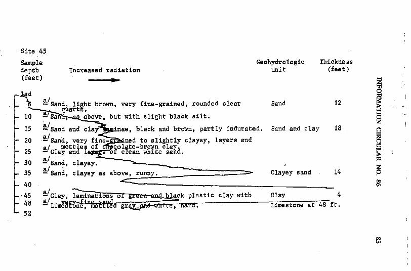
Site 45
Sample Geohydrologic Thicknessdepth Increased radiation unit (feet)(feet)
sad
Sa/and, light brown, very fine-grained, rounded clear Sand 12a quartz.
S0 - San , above, but with slight black silt.
- 15 Saand and clay nae, black and brown, partly indurated. Sand and clay 18
- 20 -/Sand, very fine. Lned to slightly clayey, layers anda/ mottles of -colate-brown clay
- 25 - Clay and 1 f clean white sand.
- 30 aSand, clayey.
- 35 a/Sand, clayey as above, runny. Clayey sand 14 0
- 40a/ !
45 - Clay, laminations o Iýe -aýd lack plastic clay with Clay 448 -Lime~ 8nemo ea gra ad-wiL, hard. Limestone at 48 ft.52
00t•)

Site 46
Sample Geohydrologic Thicknessdepth Increased radiation unit (feet)(feet)
S5 Sand light brown, very fine to fine-grained, sub-angular Sand 10 Uclear quartz, with slight silt in streaks.
10 s above, but white with occasional streaks, lightbrown s f 0
-15 Sand, as at 5ft. u w ht grayish-brown clay.- 20 Sand, as above but fa cla. Clayey sand 17
-25 Sand, very fine to fine-grainei, F riTIr t b-/ roun uartz, slightly clayey. ay 4
S30 -Clay, geienish-tan, plastic, sand = Limestone at 31 ft.-35 Limestone, whit, s with layers of green plastic
clay alternatitngo 45'.40 Limey clay, greenish-tan mottled plastic clay with ayers
and mottles of gray limestone.45 Limestone and clay layers.

Site 47
Sample Geohydrologic Thicknessdepth Increased radiation unit (feet)(feet) 0
-5 tan, very fine-grained to silt, rounded to sub-rounded-i uartz.
-10 Sand, , slight clay.-15 Sand, above, but with streaks of white sand. Sand 30
.20 Sand, ght brown, very fine-grained to silt, rounded25 nd, sub- ngular, slight clay.S25 nd as aove, but wi h very slight clay.
- 30 Sand, as a ove, Sandy clay 2 o-35 Cay, gown, sandy, with small pieces of white Clay 9 oo
chert o
40 A enish-brown. very pr climy. Limestone at 41 ft.41 imestone, very hard, cherty.44
00
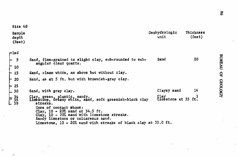
Site 48
Sample Geohydrologic Thicknessdepth unit (feet)(feet)
lsd
-5 Sand, fine-grained to slight clay, sub-rounded to sub- Sand 20angular clear quartz.
10
-15 Sand, clean white, as above but without clay. 0-20 Sand, as at 5 ft. but with brownish-gray clay.
- 25 0- 30 Sand, with gray clay. Clayey sand 14
S34 Clay, green, plastic sandy. Clay 135 Limestone, creamy white, sand, soft greenish-black clay Limestone at 35 ft.S39 streaks.
Core of contact shows:Clay, 10 - 20% sand at 34.5 ft.Clay, 10 - 20% sand with limestone streaks.Sandy limestone or calcareous sand.Limestone, 10 - 20% sand with streaks of black clay at 35.0 ft.

Site 49
Sample Geohydrologic Thicknessdepth unit (feet)(feet)
-lsd
-5 Sand light tan, very fine-grained to slight clay, sub- Sand 15rounded clear quartz.
10 Sand, as above, but whitish.
-15 Sand, as above, but with brown clay, runny.-20 Sand and clay layers, brown, very runny. Sand and clay 20
25-30
0-35 Sand, tan, very fine-grained to slight clay, sub-
rounded clear quartz. Clayey sand 5 040 Clay, greenish-tan, plastic, sandy. Clay 3
45 Limestone, hard, dense, sandy. Limestone at 43 ft.49
00-1
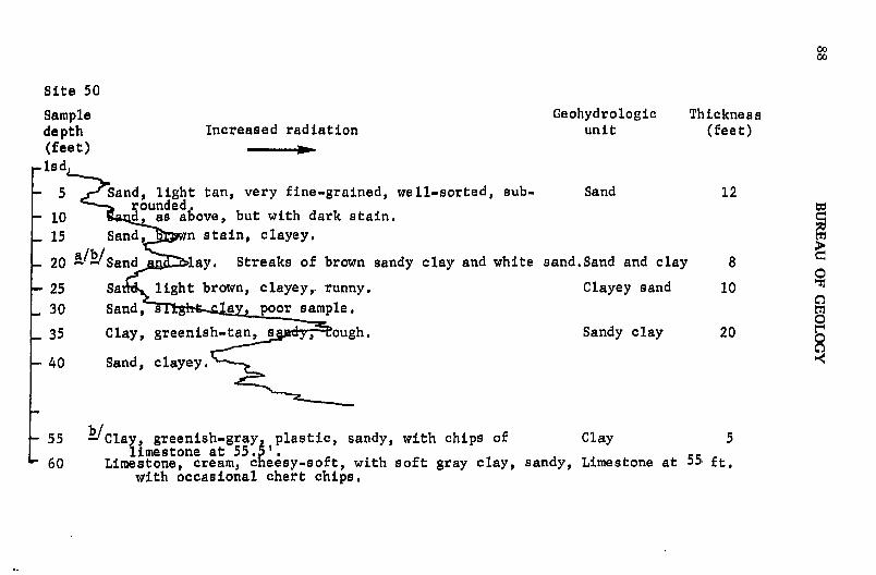
0000
Site 50
Sample Geohydrologic Thicknessdepth Increased radiation unit (feet)(feet)lsd
5 Sand, light tan, very fine-grained, well-sorted, sub. Sand 12rounded
10 d as above, but with dark stain.15 Sand, n stain, clayey.
20 a/b/Sand lay. Streaks of brown sandy clay and white sand.Sand and clay 80
25 Sa light brown, clayey,. runny. Clayey sand 10
30 Sand, s a poor sample.
35 Clay, greenish-tan, s ,d ough. Sandy clay 20 0
40 Sand, clayey.
55 b/Clay, greenish-gray, plastic, sandy, with chips of Clay 5limestone at 55.5'.
S60 Limestone, cream, cheesy-soft, with soft gray clay, sandy, Limestone at 55 ft.with occasional chert chips.

Site 51
Sample Geohydrologic Thicknessdepth Increased radiation unit (feet)(feet)
lsd
- Sand, very fine-grained, rounded, well-sorted clear Sand 10 0quartz.
-10 Sand, as above, and gray clay laminae.
1521 Sand , as above becomes dense black clay at 21'. Sand and clay 15
25 ay, gray, dense, becomes white sand at 25'.
30 So nd, very fine-grained, well-sorted, rounded, clear Sand 10rtz.
35 Sand, a e, and gray clay laminae.
40 Sand, as at 30', an - y. 042 Sand, as above, but w more clay. Sand and clay 1545 Sand and clay laminae.50 a Sand 'an~a l- llrnepae. as above; streaks of clean sand and Clay 5
green or gray clay. _______________55 Limestnr i Limestone at 55 ft.
S63 Limestone.
001O

Site 52
Sample Geohydrologic Thicknessdepth Increased radiation unit (feet)(feet) -
- 5 Saay J grained, rounded, clear quartz, slightly Sand 5
- 10 , with more gray clay.
501520 Sand, clayey. Clayey sand 27
0
- 32 Sand, bove, but more clay. .-35
S37 Sa c. e a as above, but with slightly less clay.40 Sand and clay, Sand and clay 6-45 Clay, greenish, with gray-black mottles, san y. 6S50 Clay, black, sticky, very soft. Cla - 352 Limestone, light gray, sandy. Limestone at 47 ft.

Site 53
Sample Geohydrologic Thicknessdepth Increased radiation unit (feet)(feet)
5 light tan, very fine to fine-grained, rounded Sand 5cledae artz.
10 Sand, as ove, and light gray clay.
- 15 Clayey sand 20- 2022 Sand, clayey, br sh-gray.-25 Sand, clayey, as ab but with lenses of clean white Sandy clay 5
sand.- 30 Clay, lii , h sand and sandy streaks. 0
35 Clayey sand 10- 35 Sand, wi light greenish-tan clay. Clayey sand
-40 Clay, greenish-gray, plastic, sandy, and with streaks of Clay 241.5 sanay clay.45 Limestone, whitish-gray, hard, sandy. Limestone at 41.5 ft.
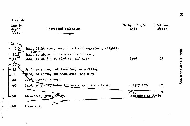
Site 54
Sample Geohydrologic Thicknessdepth Increased radiation unit (feet)(feet)
lsd
- 5 Sand, light gray, very fine to fine-grained, slightlyclayey.
"10 Sand, as above, but stained dark brown.- Sand, as at 5', mottled tan and gray. Sand 35
S2
-25 Sand, as above, but even tan; no mottling.
30 and, as above, but with even less clay.
-35 Sa dclayey, runny.
-40 Sand, as a ov , less clay. Runny sand. Clayey sand 12
Clay 3-50 Limestone, gr sandy. Limestone at 50_ft.
S60 Limestone.

Site 55
Sample Geohydrologic Thicknessdepth Increased radiation unit (feet)(feet) o-is
- 5 Sa d, light tan, very fine-grained, well-rounded, verytclay.
-10 Sand as above, but with more clay, stained dark brown. Sand 25
S15 San rown, very fine-grained, slight clay, runny.-20-25
30 Sand, as abov with streaks of gray clay. Sand and clay 12-35 nd light tan, clayey.
40 Limestonpr na ra- and hrnmn Harder brown part is Clayn 3granult crepe-rubber texture; argillaceous. Limestone at 40 ft.
45 Limestone, gray.

Site 56
Sampledepth Geohydrologic Thickness
(feet) Increased radiation unit (feet)
/Sand, white, fine-grained, well-sorted, rounded. Sand 10
10 Sand a ove, but stained black and slightly clayey.
15 020 San as at ft. but tan.25 Sand, g y, clayey. Clayey sand 28 0
30 San• gray, clayey.35 Sand, slightly less clay than above.40 Clay, reen k mottled, slightly sany and ith 7
45 - ay, as- bove -with-•hips f y • Ii ne-------. tLimestone -a 4, ft.
49 Limestone.
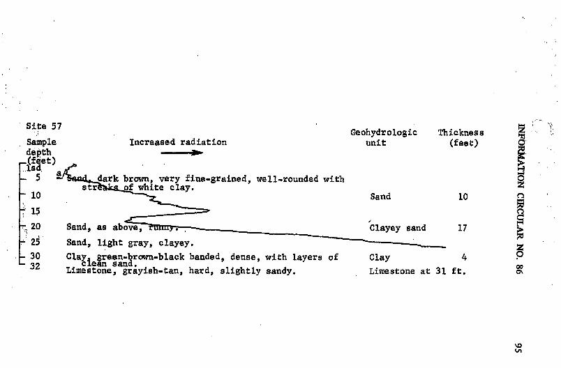
Site 57t 5 Geohydrologic Thickness
Sample Increased radiation unit (feet)depth
-(feet) ,jsd, a5 - dark brown, very fine-grained, well-rounded with 0
str of white clay. Sand10 Sand 10
15
S20 Sand, as above, - Clayey sand 17
25 Sand, light gray, clayey.
30 Clay green-brown-black banded, dense, with layers of Clay 4-32 clean sandy *Limestone, grayish-tan, hard, slightly sandy. Limestone at 31 ft.
V1l/i

Site 58
Sample Geohydrologic Thicknessdepth Increased radiation unit (feet)(feet)
asd
S a-Sand, very fine-grained, rounded, clear quartz. Sand 8
15 Sand, , u with less clay.0 Sand0
-20 Sand tn erfine-gr1ined, ell-rounded, clean Sand and clay 27wit n' o chocolate rown clay.
25 Sand, as abo but with no clay.
30 Sand, as above b ith chocolate brown clay balls.
35 Sand, light gray, clayey. --Say clay -- 3
40 Sand, as above, but with streaks and of dark gray Sand and clay 7clay; chip of white chert.
45 Limestone, grayish n, sandy, hard. Limestone at 45 ft.49 Limestone.

Site 59
Sample Geohydrologic Thicknessdepth Increased radiation unit (feet) o(feet)
asd -3 ' ht tan with brown mottles, very fine-grained, §
w i anic material.10 San , ra , very fine-grained, well rounded, clayey. Sand 5-15 Sand, as above, but ottles of reddish brown. Sand and clay 20 B18 Sand, as above, with no clay.20
25 Sand lignht brown, very fine egairn ed. with slight Clayey sand 5 Ociay In streaks. - -- - a 5
30 Saady c "lay - 535 Limestone, gray wit grPAn mnMtto-, •-ady Ll e-----. - Limestone at 35 ft.39 Limestone.

9S BUREAU OF GEOLOGY

-FLORIDA-GEOLOGICAL-SURVEY
COPYRIGHT NOTICE© [year of publication as printed] Florida Geological Survey [source text]
The Florida Geological Survey holds all rights to the source text ofthis electronic resource on behalf of the State of Florida. TheFlorida Geological Survey shall be considered the copyright holderfor the text of this publication.
Under the Statutes of the State of Florida (FS 257.05; 257.105, and377.075), the Florida Geologic Survey (Tallahassee, FL), publisher ofthe Florida Geologic Survey, as a division of state government,makes its documents public (i.e., published) and extends to thestate's official agencies and libraries, including the University ofFlorida's Smathers Libraries, rights of reproduction.
The Florida Geological Survey has made its publications available tothe University of Florida, on behalf of the State University System ofFlorida, for the purpose of digitization and Internet distribution.
The Florida Geological Survey reserves all rights to its publications.All uses, excluding those made under "fair use" provisions of U.S.copyright legislation (U.S. Code, Title 17, Section 107), arerestricted. Contact the Florida Geological Survey for additionalinformation and permissions.