Hydrogen Storage Materials Requirements to Meet the 2017
50
Hydrogen Storage Materials Requirements to Meet the 2017 On Board Hydrogen Storage Technical Targets Donald Anton Savannah River National Laboratory Troy Semelsberger Don Siegel Los Alamos National Laboratory University of Michigan Bruce Hardy Kriston Brooks Savannah River National Laboratory Pacific Northwest National Laboratory Materials Requirements Webinar June 25, 2013
Transcript of Hydrogen Storage Materials Requirements to Meet the 2017

Hydrogen Storage Materials Requirements to Meet the 2017
On Board Hydrogen Storage Technical Targets
Donald Anton Savannah River National Laboratory
Troy Semelsberger Don Siegel Los Alamos National Laboratory University of Michigan
Bruce HardyKriston Brooks Savannah River National Laboratory
Pacific Northwest National Laboratory
Materials Requirements Webinar June 25, 2013

2
Webinar Objective
Give guidance to the
materials development community as to the
important materials characteristic for both
adsorbent and chemical hydrides
required to meet the DoE Technical Targets for
Onboard Hydrogen Storage Systems
This work has been fully funded by the U.S. Department of Energy, through the Office of Energy Efficiency and Renewable
Energy, Fuel Cell Technologies Office

3
Why Perform Materials Development and System Engineering in Parallel?
Materials → Thermal → H2 Storage → Fuel Cell → Vehicle → Wheels Management BoP
Engineered Heat Transfer BoP What is Needed Materials Designs Component of the Hydrogen Storage Properties Requirements Media & System
continuous feedback with system design identifying materials requirements

4
Technical Targets for Systems DoE Targets for On‐Board Hydrogen Storage Systems
for Light Duty Vehicles
vmedia + vcomponents = Vsystem mmedia + mcomponents = Msystem cmedia + ccomponents = Csystem
& How do thermodynamic
properties affect mass and volume of system?
Gravametric Capacity kg H2/kg system 0.055 0.075
Volumetric Capacity kg H2/L system 0.04 0.07 System Cost $/kWh net TBD TBD Fuel Cost $/gge at pump 2‐6 2‐3 Min Operating Temp °C ‐40 ‐40 Max Operating Temp °C 60 60 Min Delivery Temp °C ‐40 ‐40 Max Delivery Temp °C 85 85 Cycle Life Cycles 1500 1500 Min Delivery Pressure bar 5 3 Max Delivery Pressure bar 12 12 Onboard Efficiency % 90 90 Well to Power Plant Efficiency % 60 60 System Fill Time min 3.3 2.5 Min Full Flow Rate (g/s/kW) 0.02 0.02 Start Time to Full Flow (20°C) sec 5 5 Start Time to Full Flow (‐20°C) sec 15 15 Transient Response sec 0.75 0.75 Fuel Purity %H2 99.97 99.97
Permeation, Toxicity, Safety Scc/h Meets or Exceeds
Standards
Meets or Exceeds
Standards Loss of Useable Hydrogen (g/h)/kg H2 store 0.05 0.05
Target Units
2017 DOE Goal
(System)
Ultimate DOE Goal (System)

5
Agenda
General Outline Define System
Define Technical Barriers
Identify Materials Properties That Will Meet Targets
Chemical Systems Troy Semelsberger, System Architect Chemical Systems
Kriston Brooks, Chemical System Designer
Adsorbent Systems Don Siegel, Adsorbent System Architect
Bruce Hardy, Transport Phenomenon Technology Lead

Chemical Hydrogen Storage Material Requirements
Troy A. Semelsberger
Los Alamos National Laboratory
(505) 500-2687
Kriston Brooks
Pacific Northwest National Laboratory
(509) 372-4343
DOE Webinar: 25 June 2013 6

7
Key Takeaways for Today Parameter Units Range*
Minimum Material capacity (liquids) g H2 / g material ~ 0.078 (0.085)†
Minimum Material capacity (solutions) g H2 / g material ~ 0.098 (0.106) †
Minimum Material capacity (slurries) g H2 / g material ~ 0.112 (0.121) †
Kinetics: Activation Energy kcal / mol 28–36 Kinetics: Preexponential Factor 4 x 10⁹ – 1 x 10¹⁶
Endothermic Heat of Reaction kJ / mol H2 ≤ +17 (15) †
Exothermic Heat of Reaction kJ / mol H2 ≥ -27
Maximum Reactor Outlet Temperature °C 250
Impurities Concentration ppm No a priori estimates can be quantified
Media H2 Density kg H2 / L ≥ 0.07
Regeneration Efficiency % ≥ 66.6%
Viscosity cP ≤ 1500 * (a) parameter values are based on a specific system design and component performance with fixed masses and volumes (b) values outside these ranges do not imply that a material is not capable of meeting the system performance targets (c) the material property ranges are subject to change as new or alternate technologies and/or new system designs are developed (d) the minimum material capacities are subject to change as the density of the composition changes due to reductions in the mass and volume of the storage tank or reductions in system mass are realized † values outside of parentheses are the values that correlate to the idealized system design (i.e., 30.6 kg) and the values in parentheses are those that correlate to the base system design (36.3 kg)
7

8
Introduction and Overview
Objective: Provide chemical hydrogen storage material property guidelines that will allow the overall system to meet the DOE 2017 performance targets
Approach: 1. Develop an integrated chemical hydrogen storage system for automotive applications
2. Develop a system model that predicts system performance using various drive cycles (e.g., US06)
3. Identify and size components that are material dependent (e.g., reactor, heat exchanger, etc.,) • Determine material properties for given component size
4. Determine material capacity to meet DOE 2017 performance targets
8

9
Chemical Hydrogen Storage System
9

10
HSECoE Chemical Hydrogen Storage Baseline System
10
Hydrogen Purification System
(FT-2)
Fuel Cell
Reactor (RX-1)
Volume Displacement Tank (TNK-1)
Phase Separator Ballast Tank
(PS-1)
Fill Station Fill & Drain
Ports
P S
PS
T
P
Rupture Disk @ 2 bar (INS-01)
L
Flapper Doors
½" P
last
ic
½" P
last
ic
3/8” SS
Reactor Heater (H-1)
3/8” SS
PRV @ 5 bar (V-4)
INS-08
INS-07
PRV @ 30 bar (V-2)
T
INS-06
INS-04
V-5
INS-09
INS-10
V-3
INS-11
3/8" SS
½” S
S
3/8" Al
3/8" Al
T
INS-05
Rupture Disk @ 2 bar (INS-03)
L
INS-02
½" Plastic
Pusher Fan Motor (M-5)
Gas & Liquid Radiators (RD-1/2)
T
V-1
MM
S
C
3/8"
Al
3/8” SS
C
Feed Pump (P-1)
Recycle Pump (P-2)
Ballast Tank (TNK-2)

11
86.0
Itemized Component List of our Baseline System
Item # Description Material Wt (kg) Vol (L)
Tanks and Tubing
TNK-1 Volume Displacement Tank High Density Polyethylene 6.2 65.5
NA Fill and Drain Lines 10 ft of 1/2" Plastic 0.17 0.38
NA Low T and P Lines 10 ft 3/8" Aluminum 0.12 0.2 NA High T and P Lines 10 ft 3/8" Stainless Steel 0.38 0.22 INS-01 Rupture Disk 0.6 0.16
INS-02 Level Sensor for Volume Displacement Tank 0.6 0.16
INS-03 Rupture Disk 0.6 0.16 INS-04 Pressure sensor 316L SS 0.14 0.001 Feed Loop V-1 2 Multiport Valves with Actuator Assured Automation 1.7 0.75
V-1 Flapper Valves 0.5 0.2 P-1 Feed Pump KNF NF2.35 0.3 0.3 INS-05 Temperature sensor 0.1 0.02 RX-1 Reactor SS tubing and stirrer 5 4
H-1 Reactor Heater 0.5 INS-06 Temperature sensor 0.1 0.02 INS-07 Level Sensor for P/S 0.18 0.14
Recycle Loop P-2 Recycle Pump KNF NF2.35 0.3 0.3
Item # Description Material Wt (kg) Vol (L)
Return Loop
PS-1 Gas Liquid Separator 347/347L SS 3.2 3.7
INS-08 Pressure sensor 316L SS 0.14 0.001 V-2 Pressure Relief Valve 0.3 0.1 RD-2 Liquid Radiator 304 SS 2.08 2.9
RD-2 Liquid Radiator Header 304 SS 0.16 0.06
M-5 Liquid Radiator Fan Ultra Thin Line 12V Electric Fan (Puller) Nylon 1 5.9
INS-11 Temperature sensor 0.1 0.02 V-5 Control Valve Brass 1.7 0.75
Hydrogen Discharge FT-1 Coalescing Filter SS 1.2 0.34
RD-2 Gas Radiator 304 SS 0.3 0.3
RD-2 Gas Radiator Header 304 SS 0.16 0.03 INS-09 Temperature sensor 0.1 0.02 INS-10 Pressure Switch 0.1 0.001 FT-2 H2 Clean-Up System 3.2 4 TNK-2 Additional Ballast Tank Aluminum, L/D =4 , SF = 1.5 2.6 15 FT-4 Particulate Filter SS 1.2 0.34 V-3 Pressure Regulator Gas 0.6 0.5 V-4 Pressure Relief Valve 0.6 0.16
11

12
System Components for Projected System Design
12
Required system components that are material property independent
Required system components that are material property dependent
Material Independent Components (BOP)
Material Dependent Components
e.g., valves, sensors, tubing, filters, regulators, …..
– Reactor – Hydrogen purification – Volume displacement Tank – Ballast tank – Heat exchangers
Required system components that are system independent
System Independent Material Properties
– Media hydrogen storage capacity – Regeneration efficiency – Fuel cost – Shelf-life
Baseline Idealized
Component Mass (kg)
Volume (L)
Mass (kg)
Volume (L)
BOP† 21.8 8.9 21.8 8.9
H2 Purification* 3.2 4 0 0
Heat Exchangers* 3.7 9.2 3.7 9.2
Reactor* 5 4 2.5 2
Ballast Tank* 2.6 15 2.6 15
Media + Tank‡ ≤ 65.7 ≤ 98.9 ≤ 71.4 ≤ 104.9
† BOP mass and volume were held constant * Component masses or volumes were sized independent of the material to maintain a material independent system ‡ volume displacement tank mass was fixed at 6.2 kg

13
Baseline System Mass and Volume to Meet DOE 2017 Targets
Volume Pie Chart* (L) Mass Pie Chart* (kg)
Total System Volume = 107 L Total System Mass = 102 kg DOE Volume Target = 140 L DOE Mass Target = 102 kg System Volume (excluding media) = 41.5 L System Mass (excluding media) = 36.3 kg Unused (available) Volume = 33 L Unused (available) Mass = 0 kg
* Values correspond to our baseline system design
13

14
Idealized System Mass and Volume to Meet DOE 2017 Targets
Volume Pie Chart† (L) Mass Pie Chart † (kg)
Total System Volume = 107 L Total System Mass = 102 kg DOE Volume Target = 140 L DOE Mass Target = 102 kg System Volume (excluding media) = 35 L System Mass (excluding media) = 30.6 kg Unused (available) Volume = 33 L Unused (available) Mass = 0 kg
† Values correspond to our idealized system design (30.6 kg), no purification, reactor volume = 2 L, and reactor mass = 2.5 kg
14

15
Material Properties
15

16
Material Capacity for Liquids
16
Assumptions
Objective:
Determine net usable H2 capacity for chemical hydrogen materials to meet 2017 DOE system targets given our idealized system mass (excludes media) of 30.6 kg and our baseline system (excludes media) of 36.3 kg
Fixed reactor mass 2.5 kg 5 kg
Fixed purification mass 0 kg 3.2 kg
System mass excludes media 30.6 kg 36.3 kg Media is a liquid with no phase change
Property Range
2. = * H 2 mliquid
liquid
gNet usable wt fraction H 0.078 (0.085) g
* value 0.085 represents the minimum capacity for our given baseline system mass (36.3 kg); the minimum capacity can be lowered if reductions in reactor mass, purification mass or system component masses are realized (e.g., if purification is eliminated and reactor mass halved then a liquid material capacity of 0.078 is expected)
0 2 4 6 8 10 12 14 16 0
20
40
60
80
Materials that will never meet DOE system gravimetric targets
2017 Target
5.5 (H2wt%)sys
Sys
tem
Mas
s (k
g)(E
xclu
des
Med
ia M
ass)
Net usable H2 wt% of Media
Plot of Available System Mass as a Function of Net Usable H2 wt%
(Mass)sys = (Mass)media

17
�
17
Property Range
Upper bound calculated using material = 1.50 g/mL, carrier = 0.75 g/mL, and material = 0.100 gH2/gmaterial Lower bound calculated using material = 0.80 g/mL, carrier = 1.50 g/mL, and material = 0.152 gH2/gmaterial
Objective: Determine required material capacities as a function of slurry mass fraction loadings to meet a 2017 DOE system targets given our idealized system mass (excludes media) of 30.6 kg and our baseline system (excludes media) of 36.3 kg
0.0 0.1 0.2 0.3 0.4 0.5 0.6 0.7 0.8 0.9 1.0 0.0
0.1
0.2
0.3
0.4
0.5
0.6
0.7
0.8
0.9
1.0
Upper bound
Slu
rry m
ass
fract
ion,
sl
urry
, m
Slurry volume fraction, slurry, v
Vsolids < Vliquid Vsolids > Vliquid V
solid
s = V
liqui
d
Lower
boun
d
Material Capacity for Slurries
Assumptions
System mass excludes media 30.6 kg 36.3 kg Slurry is homogeneous and non - settling
0.35 0.40 0.45 0.50 0.55 0.60 0.65 0.70 0.10
0.12
0.14
0.16
0.18
0.20
0.22
0.24
Base System Mass (36.3 kg) Idealized System Mass (30.6 kg)
Mat
eria
l Cap
acity
, m
(g H
2 / g
mat
eria
l)
Slurry Mass Fraction, slurrym (gmaterial / gslurry)
Plot of slurry mass fractions and material capacities required for a base system mass of 36.3 kg and an idealized system mass of 30.6 kg
2
,
,
= =
=
. =
solid slurry v
slurry
solid slurry m
slurry
H 2 msolid
solid
mLMax slurry volume fraction 0.5 mL
gSlurry mass fraction 0.35 0.70 g
gNet usable wt fraction H 0.112 (0.121) g
~

18
�
Material Capacity for Solutions
18
Assumptions
Objective: Determine required material capacities as a function of solute mass fraction loadings to meet 2017 DOE system targets given our idealized system mass (excludes media) of 30.6 kg and our baseline system (excludes media) of 36.3 kg
Property Range
-
solute
solution
System Mass excludes media 30.6 kg 36.3 kg No phase change Volume additivity
gMaximum solute mass fraction 0.8 g Solvent is non hydrogen bearing
Note: a solution is a two component homogeneous mixture containing a solute and a solvent. Our solution assumes a hydrogen bearing solute dissolved in a non-hydrogen bearing solvent.
0.35 0.40 0.45 0.50 0.55 0.60 0.65 0.70 0.75 0.80 0.08
0.10
0.12
0.14
0.16
0.18
0.20
0.22
0.24
Base System Mass (36.3 kg) Idealized System Mass (30.6 kg)
Mat
eria
l Cap
acity
, m
(g H
2 / g
mat
eria
l)
Solute Mass Fraction, solutionm (gsolute / gsolution)
Plot of solute mass fractions and material capacities required for a base system mass of 36.3 kg and an idealized system mass of 30.6 kg
2
, =
. =
solute solution m
solution
H 2 msolute
solute
gSolute mass fraction 0.35 0.8 g g
Net usable wt fraction H 0.098 (0.106) g
~

19
Reaction Kinetics
19
Property Ranges*
Variables
Constraints/Assumptions
Objective:
a
9 16
kcal E 28 36 mol
A 4 x 10 1 x 10 Reaction order n = 0 -1
=
=
=
a
5 17
kcal Activation Energy E 24 - 37 mol
Preexponential Factor A 10 -10
Reaction Order n 0 -1.5
Determine viable kinetics parameters to meet volume and shelf-life constraints given our baseline system design and assumptions
* these values do not take into account catalytic processes
2
o
o
e
T=60 C
shelf life X =7.2%
T = 175 C PFR X = 99%
max 2 2 H 40kW
t 60 days
V 4 L
mol H g HF 0.4 0.8 s s
Reaction is irreversible
0.0020 0.0022 0.0024 0.0026 0.0028 0.0030
-22
-20
-18
-16
-14
-12
-10
-8
-6
-4
-2
(227oC) (182oC) (144oC) (111oC) (84oC)
ln k
1/T (K-1)
Min Volume for n = 0.0 V = 4L for n = 0.0 Min Volume for n = 0.5 V = 4L for n = 0.5 Min Vol for n = 1.0 V = 4L for n = 1.0
(60oC)
Arrhenius plots showing the desirable ranges of activation energies (kcal/mol K) and preexponential factors as a function of reaction order

20
Exothermic Heat of Reaction: System Materials
20
• System is bounded by the design to accommodate ammonia borane
• Material inlet temperature = 24°C • Maximum system temperature = 250°C • Up to 50% recycle ratio
Property RangeVariables
Constraints/Assumptions
Objective: Determine the highest exothermic heat of reaction that will prevent the system materials from being exposed to temperatures greater than 250°C
,
. =
p m
2 mmaterial
JC 1500 2500 kg K net usable wt fraction H 0.085 0.092
rxn
2
kJH 27 mol H

21
Endothermic Heat of Reaction: On-board Efficiency
21
Property Range
Assumptions
reactor amb
p
No heat recovery Fixed reactor mass 2.5 (5.0) kg SS Cold Start Up T T T 150 C 4 Cold Start Ups per day Average miles driven per day 41
Jneat liquid with C 1.6 g K
Objective: Determine maximum heat of reaction to meet 90% on-board efficiency given our system designs and assumptions
°
rxn 2
SU 4 onboard T=150 C
kJH +17 (15) mol H
for = 90%
2.5 kg SS Reactor
5.0 kg SS Reactor

22
Media Hydrogen Density: Volume Displacement Tank
22
• H2 Conversion = 99% • On-Board Efficiency = 95% • Rectangular, Conical bottom HD
Polyethylene Tank, 15” tall • Tank Mass ≤ 6.2 kg
Property Range Variables
Constraints/Assumptions
Objective: Determine lower limit on the media hydrogen density subject to a maximum tank mass of 6.2 kg
2
media
media H capacity 8.0 18.5 wt.% gmedia density 0.7 1.5 mL
2 2 media
kg H H density 0.07 L for a tank mass 6.2 kg

23
Fuel Cell Impurities Objective:
system design and assumptions concentration given on our baseline Determine the maximum impurity
Constraints/Assumptions Purification Mass 3.2 kg
Adsorbent based technology
H2 Purity 99.97%
Replacement Frequency 1800 miles
The maximum impurity concentration allowed for a fixed purification mass of 3.2 kg will be a function of:
Property Range• Impurity type (e.g., fuel cell or inert diluent) • Chemical and physical properties of the The maximum allowed impurity concentration
impurity cannot be calculated a priori. Therefore, the• Hydrogen purification technology impact of impurities generated from hydrogen • Recycle/Regeneration cost and efficiency storage materials should be examined on a• Material cost and availability case-by-case basis
23

24
Summary: Material Property Guidelines Parameter Symbol Units Range* Influence Assumptions
Minimum Material capacity (liquids)
mat g H2 / g material ~ 0.078 (0.085)† System
• System mass (excludes media) = 30.6 kg (36.3 kg) • 5.6 kg of H2 stored • Liquid media (neat) • Media density = 1.0 g/mL
Minimum Material capacity (solutions)
mat g H2 / g material ~ 0.098 (0.106) † System • System mass (excludes media) = 30.6 kg (36.3 kg) • Solute mass fraction = 0.35 ~ 0.80 • Solution density = 1.0 g/mL
Minimum Material capacity (slurries)
mat g H2 / g material ~ 0.112 (0.121) † System
• System mass (excludes media) = 30.6 kg (36.3 kg) • Non-settling homogeneous slurry • Slurry mass fraction = 0.35 ~ 0.70 • Slurry volume fraction = 0 ~ 0.5 • Slurry density = 1.0 g/mL
Kinetics: Activation Energy Ea kcal / mol 28–36 Reactor and
Shelf life
• Vreactor ≤ 4 L • Shelf life ≥ 60 days • Reaction order, n = 0 – 1 Kinetics:
Preexponential Factor A 4 x 10⁹ – 1 x 10¹⁶
Endothermic Heat of Reaction Hrxn kJ / mol H2 ≤ +17 (15) † On-board efficiency
• On-board Efficiency = 90% • # Cold Startups = 4 • T = 150 °C with no heat recovery • neat liquid (Cp = 1.6 J/g K) • Reactor mass = 2.5 kg SS (5.0 kg SS)
Exothermic Heat of Reaction Hrxn kJ / mol H2 ≤ -27 • Tmax = 250°C
• Recycle ratio @ 50%
Maximum Reactor Outlet Temperature Toutlet °C 250 Heat Exchanger
• Liquid Radiator = 2.08 kg • Gas Radiator = 0.3 kg • Ballast Tank = 2.6 kg
Impurities Concentration yi ppm No a priori estimates
can be quantified Purification • madsorbent ≤ 3.2 kg
Media H2 Density mat) (m)(mat) kg H2 / L ≥ 0.07 Tank size System • HD polyethylene tank ≤ 6.2 kg
Regen Efficiency regen % ≥ 66.6% Well-to-Power Plant Efficiency
• On-board Efficiency = 90% • WTPP efficiency = 60%
Viscosity cP ≤ 1500 Fill time Pump size On-board efficiency
None
* (a) parameter values are based on a specific system design and component performance with fixed masses and volumes (b) values outside these ranges do not imply that a material is not capable of meeting the system performance targets (c) the material property ranges are subject to change as new or alternate technologies and/or new system designs are developed (d) the minimum material capacities are subject to change as the density of the composition changes due to reductions in the mass and volume of the storage tank or reductions in system mass are realized † values outside of parentheses are the values that correlate to the idealized system design (i.e., 30.6 kg) and the values in parentheses are those that correlate to the baseline system design (36.3 kg)
24

25
Next Steps
25
• Researchers develop new materials • Evaluate relative to targets conditions described herein • As materials show promise, they can be evaluated using the Chemical
Hydrogen Storage System Models developed by the HSECoE • System models offer higher fidelity and provide additional guidance
relative to the specific properties of the newly developed materials

26
Disclaimer • The material properties detailed in this presentation were prepared in order to provide general
guidance for chemical hydrogen storage researchers and therefore should not be taken as rigid constraints.
• The presented material properties were developed within the constraints of our system design, component sizing, assumptions, and system operating conditions. In addition, the ranges in material properties are not specific to a particular material, and therefore can be applied to the general class of chemical hydrogen storage media.
• Material property values just outside the material ranges presented do not imply that a material is not capable of meeting the system performance targets, but rather that the material will require further examination.
• The material property ranges are subject to change as new technologies and/or new system designs are developed.
• The minimum material capacities are subject to change if the density of the composition changes because of reductions in the mass and volume of the storage tank.
• Material properties that fall within the presented material properties do not establish commercial viability or commercial success.
26

27
Acknowledgements
27
Ned Stetson and Jessie Adams
Fuel Cell Technologies Office

28
Adsorption-Based Hydrogen Storage System: An Overview
Don Siegel System Architect, Adsorbent System Mechanical Engineering Department,
University of Michigan
DOE Hydrogen Storage Webinar June 25, 2013
28

29
Goals for the Adsorbent System
• Model, design, construct, and evaluate an adsorbent-based hydrogen storage system that has the potential to meet DOE 2017 targets.
• Reveal design tradeoffs, e.g.: → Gravimetric vs. volumetric density → Capacity & cost vs. fill time
• Guide materials development → Identify materials properties that most strongly impact system performance.
29

30
Powder Form
3 to 6 mm
Pellet Form
50 mm
Large Compressed Form “Hockey Puck”
Many Design Choices
Adsorbent Form Selection: Powder Form Pelletized Form Monolithic Forms (Puck) ENG or other thermal
enhancement
Tank Selection: Aluminum Type I Stainless Steel Type I Composite Fiber Type III Composite Fiber Type IV
Tank Internals/HX Selection: Resistance Heater
o Fin and tube o Wire mesh o Hex/Honeycomb
MATI / Isolated-H2 insert
The Center has aimed to identify optimal combinations of adsorbent morphology, tank materials, and tank internals/heat exchanger design
30

31
Materials Selection
&
The Center has selected MOF-5 as its baseline adsorbent
[1] Theoretical Limits of Hydrogen Storage in Metal-Organic Frameworks: Opportunities and Trade-Offs, Goldsmith, Wong-Foy, Cafarella, and Siegel, Submitted. [2] Recommended Best Practices for the Characterization of Storage Properties of Hydrogen Storage Materials, K. J. Gross, et al., V2-81
[2]
31

32
Example System: Modular Adsorption Tank Insert (MATI) The MATI concept allows for isolated heating/cooling and densified media
• 0.32 g/cc compacted MOF-5, with 91.6% packing density
• Modular Adsorption Tank Insert (MATI) • Internal HX with isolated-LN2 cooling and
isolated-GH2 heating
• Type 1 Al (6061-T6) Tank • LN2 vessel wall chilling channels • Single tank with oblate endcaps • Full tank: P = 100 bar, T = 80 K • Empty tank: P = ~5 bar, T = ~140 K 32
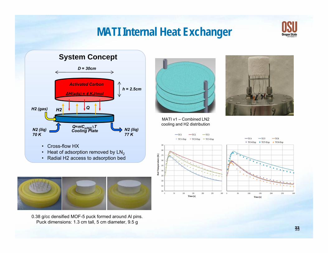
MATI Internal Heat Exchanger
Q
Activated Carbon
N2 (liq) 70 K
N2 (liq) 77 K
Q=mሶCp(N2)∆T
H2 (gas)
ΔH(ads) = 4 KJ/mol
Cooling Plate
D = 30cm
h = 2.5cm
System Concept
• Cross-flow HX • Heat of adsorption removed by LN2 • Radial H2 access to adsorption bed
H2
MATI v1 – Combined LN2 cooling and H2 distribution
0.38 g/cc densified MOF-5 puck formed around Al pins. Puck dimensions: 1.3 cm tall, 5 cm diameter, 9.5 g
3333

34
Hex-Cell/Flow-through System Concept
34
The Hex-Cell system design uses powder MOF-5 with flow-through cooling & resistive heating
Resistance Heater
35
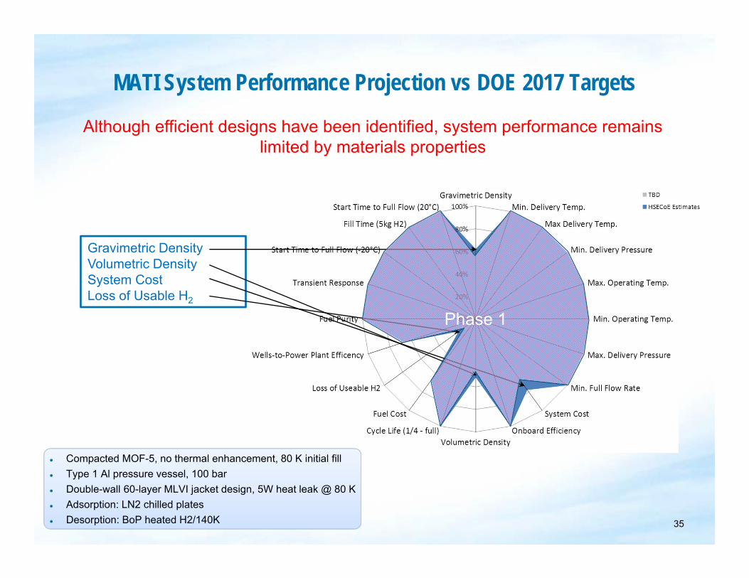
MATI System Performance Projection vs DOE 2017 Targets
Gravimetric Density Volumetric Density System Cost Loss of Usable H2
Phase 1
● Compacted MOF-5, no thermal enhancement, 80 K initial fill ● Type 1 Al pressure vessel, 100 bar ● Double-wall 60-layer MLVI jacket design, 5W heat leak @ 80 K ● Adsorption: LN2 chilled plates ● Desorption: BoP heated H2/140K
Although efficient designs have been identified, system performance remains limited by materials properties
35

36
Improvements needed to reach DOE 2017 targets
Step Description
Phase 1 Baseline – Activated Carbon; Type 3 tank; A Full at 80K, 200 bar; FT Cooling + Generic Resistance Heater
B Set Operating Conditions to 80 K, 100 bar and Type 1 Al Tank C Identify Internal Heat Exchanger Design: MATI D Change Material from Activated Carbon to 0.32 g/cc Compacted MOF-5 E Improve BOP Components (reduce mass and volume by 25%)
F Maintain Capacity with increased Operating Temperature (reduce MLVI by 50%; remove LN2)
G Increase Material Capacity to 120% of Powdered MOF-5 H Increase Material Capacity to 140% of Powdered MOF-5 I Increase Material Capacity to 160% of Powdered MOF-5 J Increase Material Capacity to 180% of Powdered MOF-5 K Increase Material Capacity to 200% of Powdered MOF-5 L Increase Material Capacity to 220% of Powdered MOF-5
36

37
Future Work-Phase 3: Adsorbent System Build/Test Heat Exchange Systems Containment Test Facilities
HexCell/MOF-5 Powder 2 Liter Type 1 Flow-Through Cooling Segmented Al Tank
Resistance Heating
0.3g/cc MOF-5 Puck MATI Heating/Cooling Type 1 SS
Pressure Vessel 37
Adsorbent Acceptability Envelope
Bruce J. Hardy Claudio Corgnale David Tamburello
Savannah River National Laboratory
DOE Webinar June 25, 2013

39
Introduction and Overview • Adsorbent Acceptability Envelope (AAE)
Overall objective: Identify coupled adsorbent and storage vessel properties that make it possible to meet performance targets
Accomplished in two stages: Stage 1 - Identify isotherms that yield necessary amount of usable (not just total) hydrogen
Depends on final and initial states Determined through isotherm parameters
» So far, have considered UNILAN and Dubinin-Astakhov-Radushkevich isotherms
AAE can determine parameters that optimize available hydrogen Isotherms determine excess differential enthalpy of adsorption
Stage 2 - Determine coupled adsorbent/storage system parameters required to meet targets
Requires all items in first stage plus design concepts for charging and discharging

40
Stage 1 - Optimal Isotherm Parameters • Optimization of Available Hydrogen
Specify initial and final states via temperature and pressure Determine optimal isotherm parameters with respect to usable amount of stored hydrogen
For UNILAN, optimize: nmax, Emax, Emin
Can also optimize with respect to constrained pore volume and entropy change Can include constrained pressure & temperature in optimization parameters
Isosteric heat for optimized parameters is calculated
Material developers will need to fit data to isotherms or attempt to create adsorbents with target isotherm parameters

41
Stage 1 - Example Values for Optimal Parameters
Charged State: Tchg=80K Pchg=60 bar
Discharged State: Tdisch=160K Pdisch=5 bar
Constraints: 0 < nmax ≤ 120, Emin > 0,
UNILAN Isotherm Model
Emax ≥ Emin +1
UNILAN isotherm has singularity in isosteric heat if Emax = Emin
nmax(mol/kg) Emax(J/mol) Emin (J/mol) S0(J/mol-K) Usable Hydrogen (kg_H2/kg_ads)
MOF-5 60.77 4497.9 1997.1 -64.16 0.086 Optimized 120 4655.5 4654.5 -64.16 0.217
Optimized when Emax=Emin No heterogeneity for adsorption sites Consistent with Bhatia and Myers, “Optimum Conditions for Adsorptive Storage,” Langmuir 2006 (2)

42
Stage 1 – Isosteric Heat at Optimized UNILAN Parameters
3000
4000
5000
6000
0 20 40 60 80 100 120
Isos
teric
Hea
t (J/
mol
)
Pressure (bar)
Isosteric Heat vs Pressure
Optimized UNILAN Parameters
nmax 120 mol/kg Emax 4655 J/mol Emin 4654 J/mol S0 -64.16 J/mol
At optimized UNILAN parameters the isosteric heat is nearly constant
ݎݐݏݏܫ ݐܪ ≡ ∆ ൌ ଶ
ቤ
Common definition of isosteric heat
Emax, Emin

43
Stage 1 - Relation Between Optimum Parameters for Example Values
nmax(mol/kg) Emax(J/mol) Emin(J/mol) 30 4655.5 4654.5
50 4655.5 4654.5
70 4655.5 4654.5
100 4655.5 4654.5
120 4655.5 4654.5
150 4655.5 4654.5
200 4655.5 4654.5
At optimum, Emax and Emin are independent of nmax
50
100
150
200
250
0 50 100 150 200 250
Usa
ble
Hyd
roge
n (m
ol/k
g_ad
s)
nmax
Usable Hydrogen vs nmax
At optimum, usable H2 is linear with respect to nmax, as would be expected from the UNILAN model
Volumetric usable H2 is linear with respect to ads*nmax

44
Stage 1 - Isotherm Parameter Range
• Identify (non-optimal) parameter ranges that meet performance targets for hydrogen storage
Based on UNILAN isotherm Employed usable H2 corresponding to charged and discharged states
• Targets used as examples in this presentation are the DOE Ultimate Technical Targets for Light Duty Vehicles
Gravimetric capacity 0.075 kg_H2/kg_system Volumetric capacity 0.070 kg_H2/L_system

45
Stage 1 - Relation Between nmax, Emax & Emin
1000
2000
3000
4000
5000
1000 1500 2000 2500 3000
E max
(J/m
ol)
Emin (J/mol)
With Respect to Volumetric Target
nmax=60 mol/kg nmax=100 mol/kg nmax=200 mol/kg
MOF-5 Density ≈ 130 kg/m3
• For volumetric targets it was assumed that the density was 8x130 kg/m3
Charged State: Tchg=80K Pchg=60 bar
Discharged State: Tdisch=160K Pdisch=5 bar
1000
2000
3000
4000
5000
6000
1000 1500 2000 2500 3000
E max
(J/m
ol)
Emin (J/mol)
With Respect to Gravimetric Target nmax=60 mol/kg
MOF-5 Emax & Emin
nmax=100 mol/kg
nmax=200 mol/kg

46
Stage 2 – Coupled Adsorbent and Storage System
• Meeting the technical targets requires more than a definition of gas storage properties (isotherm)
Adsorbent must interface with the storage system Includes heat and mass transfer
• Stage 1 only addressed part of the adsorbent storage system requirements
Did not consider any kind of transport
• Upshot is that gas uptake alone does not completely determine if the adsorbent and storage system can meet technical targets

47
Stage 2 –Storage System Operation
• During charging: Heat due to pressure work and enthalpy of adsorption must be removed to maintain target temperature
Need sufficiently high thermal diffusivity or sufficiently high thermal conductivity for steady state
Can modify adsorbent or add amendments to increase thermal conductivity Can closely space heat transfer surfaces Adsorbent permeability must accommodate flow-through cooling, if used Entire mass of adsorbent may not reach target temperature
Can compensate by increasing total mass of adsorbent Adsorbent must be sufficiently permeable that gas transport to adsorption sites is not impeded
• However, adsorbent and system modifications affect gravimetric and volumetric capacity

48
Stage 2 – Adsorbent Storage System Coupling • The interaction between the adsorbent and storage
system is determined through numerical models Transient calculations Models include:
Isotherm parameters Adsorbent thermal conductivity, specific heat, density and porosity Hydrogen flowrate, inlet pressure and characteristic spacing for heat transfer surfaces
Differential excess internal energy is calculated from the isotherm
Isotherm is used to calculate the enthalpy of adsorption • System design
Flow-through cooling Cooling & heating using:
Parallel heat transfer surfaces (MATI) Cylindrical surfaces (Hex-cell configuration)

49
Summary • Assessment of adsorbent viability is conducted in 2
stages • In the first stage, the amount of usable hydrogen
stored by the adsorbent is evaluated Determines whether an existing adsorbent can possibly meet the technical targets Determines parameter ranges that an adsorbent must have to meet technical targets Determines optimal adsorbent parameters
• If the adsorbent meets criteria for Stage 1, then the second stage analysis is applied
Determines whether system meeting technical targets can be designed for an existing adsorbent Determines coupled adsorbent and system parameter ranges required to meet the technical targets

50
Thanks for Listening!
Questions?