Hydrogen Storage in Wind Turbine Towers - National … · 2013-09-04 · Hydrogen Storage in Wind...
39
Hydrogen Storage in Wind Turbine Towers September 2003 • NREL/TP-500-34656 R. Kottenstette Summer intern from Santa Clara University J. Cotrell National Renewable Energy Laboratory National Renewable Energy Laboratory 1617 Cole Boulevard Golden, Colorado 80401-3393 NREL is a U.S. Department of Energy Laboratory Operated by Midwest Research Institute • Battelle • Bechtel Contract No. DE-AC36-99-GO10337
Transcript of Hydrogen Storage in Wind Turbine Towers - National … · 2013-09-04 · Hydrogen Storage in Wind...
Hydrogen Storage in Wind Turbine Towers
September 2003 • NREL/TP-500-34656
R. Kottenstette Summer intern from Santa Clara University J. Cotrell National Renewable Energy Laboratory
National Renewable Energy Laboratory 1617 Cole Boulevard Golden, Colorado 80401-3393 NREL is a U.S. Department of Energy Laboratory Operated by Midwest Research Institute • Battelle • Bechtel
Contract No. DE-AC36-99-GO10337
National Renewable Energy Laboratory 1617 Cole Boulevard Golden, Colorado 80401-3393 NREL is a U.S. Department of Energy Laboratory Operated by Midwest Research Institute • Battelle • Bechtel
Contract No. DE-AC36-99-GO10337
September 2003 • NREL/TP-500-34656
Hydrogen Storage in Wind Turbine Towers
R. Kottenstette Summer intern from Santa Clara University J. Cotrell National Renewable Energy Laboratory Prepared under Task No. WER3.3250

NOTICE This report was prepared as an account of work sponsored by an agency of the United States government. Neither the United States government nor any agency thereof, nor any of their employees, makes any warranty, express or implied, or assumes any legal liability or responsibility for the accuracy, completeness, or usefulness of any information, apparatus, product, or process disclosed, or represents that its use would not infringe privately owned rights. Reference herein to any specific commercial product, process, or service by trade name, trademark, manufacturer, or otherwise does not necessarily constitute or imply its endorsement, recommendation, or favoring by the United States government or any agency thereof. The views and opinions of authors expressed herein do not necessarily state or reflect those of the United States government or any agency thereof.
Available electronically at http://www.osti.gov/bridge
Available for a processing fee to U.S. Department of Energy and its contractors, in paper, from:
U.S. Department of Energy Office of Scientific and Technical Information P.O. Box 62 Oak Ridge, TN 37831-0062 phone: 865.576.8401 fax: 865.576.5728 email: [email protected]
Available for sale to the public, in paper, from:
U.S. Department of Commerce National Technical Information Service 5285 Port Royal Road Springfield, VA 22161 phone: 800.553.6847 fax: 703.605.6900 email: [email protected] online ordering: http://www.ntis.gov/ordering.htm
Printed on paper containing at least 50% wastepaper, including 20% postconsumer waste
iii
Executive Summary Low-cost hydrogen storage is recognized as a cornerstone of a renewables-hydrogen economy. Modern utility-scale wind turbine towers are typically conical steel structures that, in addition to supporting the rotor, could be used to store hydrogen. This study has three objectives:
1) Identify the paramount considerations associated with using a wind turbine tower for hydrogen storage
2) Propose and analyze a cost-effective design for a hydrogen-storing tower 3) Compare the cost of storage in hydrogen towers to the cost of storage in
conventional pressure vessels. The paramount considerations associated with a hydrogen tower are corrosion (in the form of hydrogen embrittlement) and structural failure (through bursting or fatigue life degradation). Although hydrogen embrittlement (HE) requires more research and experimentation, it does not appear to prohibit the use of turbine towers for hydrogen storage. Furthermore, the structural modifications required to store hydrogen in a tower are not cost prohibitive. We discovered that hydrogen towers have a “crossover pressure” at which their critical mode of failure crosses over from fatigue to bursting. The crossover pressure for many turbine towers is between 10 and 15 atmospheres. The cost of hydrogen storage per unit of storage capacity is lowest near the crossover pressure. Above the crossover pressure, however, storage costs rise quickly. The most cost-effective hydrogen tower design would use substantially all of its volume for hydrogen storage and be designed at its crossover pressure. An 84-m tall hydrogen tower for a 1.5-MW turbine would cost an additional $84,000 (beyond the cost of the conventional tower) and would store 950 kg of hydrogen. The resulting incremental storage cost of $88/kg is approximately 30% of that for conventional pressure vessels.

iv
Table of Contents List of Figures ..................................................................................................................... v Introduction......................................................................................................................... 1 Benchmarks and Assumptions............................................................................................ 1 Conventional Towers .......................................................................................................... 2 Conventional Pressure Vessels ........................................................................................... 3 Hydrogen Tower Considerations ........................................................................................ 3 Corrosion............................................................................................................................. 3
Hydrogen Attack......................................................................................................... 4 Hydrogen Embrittlement ............................................................................................ 4
Structural Analysis.............................................................................................................. 6 Loads and Stresses ...................................................................................................... 6 Fatigue Failure ............................................................................................................ 7 Crossover Pressure...................................................................................................... 8 Tower Radius and Taper ............................................................................................. 9
Design of a Hydrogen Tower............................................................................................ 11 Cost Analysis .................................................................................................................... 11
Cost Based on Storage Volume ................................................................................ 12 Storage Cost per Tower Section ............................................................................... 13 Cost Based on Storage Pressure................................................................................ 14
Conceptual Designs .......................................................................................................... 16 Comparison: Towers, H2 Towers, Pressure Vessels......................................................... 20 Conclusions....................................................................................................................... 22 Future Work ...................................................................................................................... 23 References......................................................................................................................... 25 Further Reading ................................................................................................................ 26 Appendix A: Derivation of Wall Thickness Equation...................................................... 27 Appendix B: Derivation of Equation for Crossover Pressure........................................... 29 Appendix C: Cost of Wall Reinforcement Is Independent of Tower Radius ................... 31
v
List of Figures Figure 1: Baseline tower model. ...................................................................................... 2 Figure 2: Wall thickness as a function of pressure for different failure modes............... 8 Figure 3: Plot of the thickness equation for three tower radii. ...................................... 10 Figure 4: Mass-based model for cost of end caps.......................................................... 11 Figure 5: Effect of storage volume on cost/mass ratio. ................................................. 13 Figure 6: Cost/mass ratio for tower sections. ................................................................ 14 Figure 7: Cost/mass ratio as a function of pressure. ...................................................... 15 Figure 8: Pressure-based comparison. ........................................................................... 16 Figure 9: Full hydrogen tower. ...................................................................................... 16 Figure 10: Hydrogen tower with internal power cables. ................................................. 17 Figure 11: Hydrogen tower, alternate foundation design. ............................................... 18 Figure 12: Storage in the base of a hydrogen tower. ....................................................... 19 Figure 13: Hydrogen tower cost summary. ..................................................................... 20 Figure 14: Cost comparison: a tower, an H2 tower, and pressure vessels. ...................... 22
1
Introduction Low-cost hydrogen storage is recognized as a cornerstone of a renewables-hydrogen economy. Modern utility-scale wind turbine towers are typically conical steel structures that, in addition to supporting the rotor, could be used to store hydrogen. During off-peak hours, electrolyzers could use energy from the wind turbines or the grid to generate hydrogen and store it in turbine towers. The stored hydrogen could later be used to generate power via a fuel cell during times of peak demand. This capacity for energy storage could significantly mitigate the drawbacks to wind’s intermittent nature and provide a cost-effective means of meeting peak demand. Storing hydrogen in a turbine tower appears to have been first suggested by Lee Jay Fingersh at the National Renewable Energy Laboratory (NREL) (Fingersh 2003). As outlined above, this technology could play an important role in the hydrogen economy and is, therefore, worth exploring. The objectives of this paper are as follows:
1) Identify the paramount considerations associated with using a wind turbine tower for hydrogen storage.
2) Propose and analyze a cost-effective design for a hydrogen-storing tower. 3) Compare the cost of storage in hydrogen towers to the cost of hydrogen storage in
conventional pressure vessels. This study engages these objectives within the wider framework of NREL’s WindSTORM study that assesses the larger economic context of a complete wind-hydrogen system. Various balance of station costs such as transportation, licensing, and piping are therefore outside the scope of this report. This paper outlines the assumptions made during this study, outlines primary considerations associated with a hydrogen tower, highlights design characteristics of a cost-effective hydrogen tower, presents several conceptual designs, and assesses the feasibility of the concept based on comparisons to conventional towers and pressure vessels.
Benchmarks and Assumptions Electrolyzers are assumed to be the source of hydrogen to be stored in turbine towers. Proton exchange membrane (PEM) and high-pressure alkaline electrolyzers are capable of producing hydrogen at pressures up to 15 atmospheres. As will later be demonstrated, the pressures considered for hydrogen tower storage are below 15 atmospheres. It is therefore sufficient, for the purposes of this report, to simply acknowledge that hydrogen stored above 15 atmospheres is subject to additional compression costs without including the cost of compression in the following analysis. Information regarding conventional wind turbine towers and pressure vessels formed the starting point of our analysis. The following sections present background information in these two areas.
2
Conventional Towers We chose the 1.5-MW tower model specified in the WindPACT Advanced Wind Turbine Designs Study as our baseline conventional tower. The specified tower was constructed of tubular steel and designed to withstand peak and fatigue bending moments at the base and top. It has a linear taper of diameter and wall thickness and a constant
thicknessWalldiameterTower
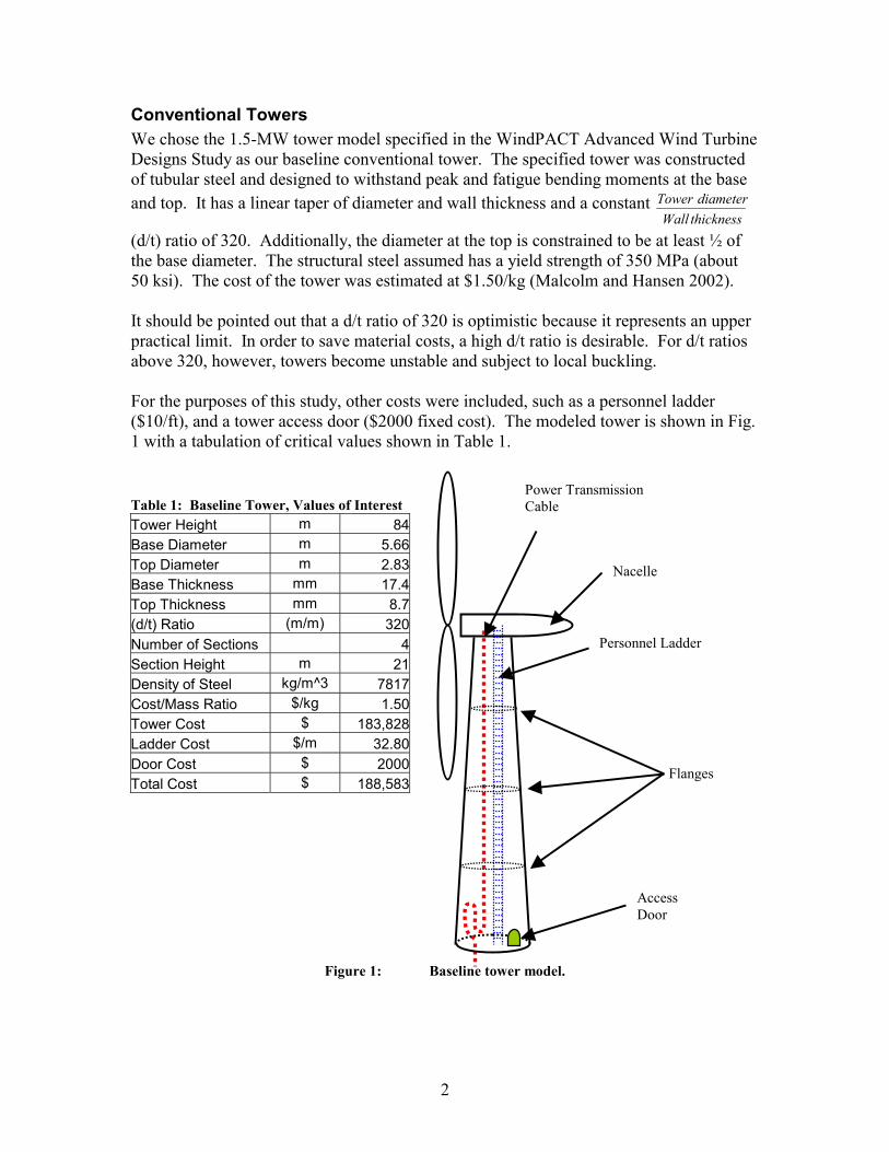
(d/t) ratio of 320. Additionally, the diameter at the top is constrained to be at least ½ of the base diameter. The structural steel assumed has a yield strength of 350 MPa (about 50 ksi). The cost of the tower was estimated at $1.50/kg (Malcolm and Hansen 2002). It should be pointed out that a d/t ratio of 320 is optimistic because it represents an upper practical limit. In order to save material costs, a high d/t ratio is desirable. For d/t ratios above 320, however, towers become unstable and subject to local buckling. For the purposes of this study, other costs were included, such as a personnel ladder ($10/ft), and a tower access door ($2000 fixed cost). The modeled tower is shown in Fig. 1 with a tabulation of critical values shown in Table 1.
Table 1: Baseline Tower, Values of Interest Tower Height m 84Base Diameter m 5.66Top Diameter m 2.83Base Thickness mm 17.4Top Thickness mm 8.7(d/t) Ratio (m/m) 320Number of Sections 4Section Height m 21Density of Steel kg/m^3 7817Cost/Mass Ratio $/kg 1.50Tower Cost $ 183,828Ladder Cost $/m 32.80Door Cost $ 2000Total Cost $ 188,583
Figure 1: Baseline tower model.
Personnel Ladder
Power Transmission Cable
Flanges
Nacelle
Access Door
3
Conventional Pressure Vessels Industrial pressure vessels are often built of carbon steel similar to that used in turbine tower construction. Although the most economical pressure vessel geometry is long and slender, vessels are often limited by shipping constraints to a practical length of about 25 meters. This length limitation means that in order to better distribute the high fixed costs associated with nozzles and manways, pressure vessels are designed with relatively large diameters and high pressure ratings. Although higher pressures reduce the cost per kg of stored gas, higher pressures require additional compression costs. In this paper, storage devices are often compared based on a cost/mass ratio. This ratio is the cost (in dollars) of a storage device divided by the mass of deliverable hydrogen gas stored. The cost/mass ratio is used because it is more convenient than the common practice of citing a volumetric capacity and a pressure rating for each storage device. Use of the cost/mass ratio does, however, make the given values accurate only for hydrogen storage. Deliverable hydrogen is the amount of hydrogen that can be taken from a vessel while maintaining the required minimum feed pressure. In pressure vessels, a certain amount of gas is required to provide a base pressure. This gas must always remain in the vessel and is therefore inaccessible. This gas is most appropriately counted as a fixed cost rather than storage capacity. In some scenarios, such as underground storage, the cost of inaccessible gas can be significant. In our study, however, this cost is neglected for several reasons. First, fuel cells are the hydrogen consumption device assumed for this study; these devices only require a feed pressure slightly above atmospheric pressure. Further, the cost of the initial hydrogen required to fill the tower to atmospheric pressure is negligible when compared to other storage-related costs. It should also be mentioned that where the mass of pressurized hydrogen is computed, hydrogen is modeled as an ideal gas. This approximation is sufficiently accurate for the temperatures and pressures considered in this study.
Hydrogen Tower Considerations Hydrogen storage creates a number of additional considerations in turbine tower design. Under certain conditions, hydrogen tends to react with steel, adversely affecting several of steel’s engineering properties, including ductility, yield strength, and fatigue life. Additionally, storing hydrogen at pressure significantly increases the stresses on the tower; therefore, storing hydrogen at pressure will likely require wall reinforcement. These factors require a structural analysis to evaluate how internal pressure may affect the tower’s design life.
Corrosion Both atmospheric corrosion and hydrogen embrittlement must be considered with regard to a hydrogen tower. Conventional turbine towers are adequately protected from atmospheric corrosion by a layer of paint. When a tower is used to store a pressurized gas, however, it becomes
4
subject to the guidelines set forth in the American Society of Mechanical Engineers (ASME) Boiler and Pressure Vessel Code. The ASME code requires that paint not be considered an adequate form of protection for the interior of pressure vessels. Enough material must therefore be added to anticipate corrosion (ASME 2001). Fortunately, the interior of a hydrogen tower is a controlled environment. Hydrogen from a PEM electrolyzer does not contain contaminants that cause atmospheric corrosion (of primary concern are sulfur dioxide and chlorine). The product hydrogen (which would be fully saturated with water vapor) could be dried to below the critical humidity level (less than 80% relative humidity) at minimal cost. Under these conditions, corrosion would penetrate the steel’s surface at the negligible rate of less than 0.1 µm per year (Roberge 1999).
Hydrogen Attack One of the two primary modes of corrosion failure when steel is exposed to a hydrogen environment is hydrogen attack (Mohitpour, Golshan, and Murray 2000). Although some sources do not distinguish hydrogen attack from hydrogen embrittlement (HE), other sources distinguish them by their differing responses to temperature. It is important not to confuse hydrogen attack, a phenomenon that occurs only at high temperatures, with HE, a phenomenon that primarily damages materials at ambient temperatures. Hydrogen attack, also known as hydrogen-induced cracking, is a process wherein hydrogen diffuses through the steel’s lattice structure, coalescing at voids and inclusions where the hydrogen reacts with the carbon present in the steel. This results in decarburization, as well as the formation of methane gas. The methane gas exerts an internal pressure, causing fissures or internal cracking. Hydrogen attack does not occur below 200O C; for this reason it is commonly called high-temperature hydrogen attack. It is anticipated that hydrogen storage in turbine towers will be at or near ambient temperatures (25O-30O C), which are far enough below the 200O C threshold to make hydrogen attack an unlikely phenomenon.
Hydrogen Embrittlement Hydrogen environment embrittlement (HEE) is the type of embrittlement that may be caused by subjecting metal to a hydrogen-rich environment (this is distinguished from internal hydrogen embrittlement, wherein hydrogen is produced inside a metal’s structure, usually by a processing technique). HEE is a process in which atomic hydrogen (H as opposed to H2) adsorbs to a metal’s surface and causes brittle failure far below the yield strength of an affected material. Many factors influence a component’s susceptibility to hydrogen embrittlement. Those factors relevant to turbine towers consist of environmental effects including temperature, pressure, and hydrogen purity, as well as material properties including grain size, hardness, and strength. This section explores the effect that hydrogen embrittlement may have on a turbine tower.
5
Evidence suggests that, unlike hydrogen attack, hydrogen environment embrittlement may be most severe at ambient temperatures (Mohitpour, Golshan, and Murray 2000; Gray 1974). Like hydrogen attack, however, HEE becomes more severe with increasing pressure. Test data suggests that the degree of embrittlement is proportional to the square root of hydrogen gas pressure (Gray 1974). This suggests that designing turbine towers for relatively low-pressure storage may help prevent hydrogen embrittlement. It is fortunate, therefore, that the storage pressures under consideration are only about 10% of hydrogen pipeline operating pressures. Hydrogen gas purity is another major environmental factor controlling HE. Experimental evidence has shown that crack propagation in a stressed specimen could be controlled by the introduction of oxygen into the hydrogen environment. Investigators demonstrated that a crack propagating in a pure hydrogen environment could be stopped with the introduction of as little as 200 ppm oxygen at atmospheric pressure (Gray 1974). Because the method of H2 production under consideration is via an electrolyzer, O2 gas will be readily available. Although adding O2 to H2 can result in an explosive mixture, adding the necessary levels of O2 is expected to have little effect on safety. This is because the required oxygen concentration (approximately 200 ppm) is far above the upper combustible limit of hydrogen in oxygen (93.9% by volume). Two hundred ppm oxygen in hydrogen represents only 0.02% (by volume) of the oxygen required to create an explosive environment. Larger grains with precipitates heavily concentrated along grain boundaries can also expedite HE because they allow for easier diffusion of hydrogen through the metal’s lattice structure (Gray 1974). The Sourcebook for Hydrogen Applications lists proper control of grain size as a successful measure of HE prevention (Bain et al., 1998). Grain size is controlled in the steel forming and treatment process. Fortunately, selection of steel plate with the appropriate grain size is not anticipated to be difficult. Increased material hardness can also magnify the effects of hydrogen embrittlement. Typically, hardness is increased by causing residual tensile stresses in a material’s surface through treatments like forging, cold rolling, or welding. Additionally, it is theorized that when hydrogen adsorbs to a material’s surface, it decreases the energy required to form a surface crack (Mohitpour, Golshan, and Murray 2000). The combination of these two factors facilitates the formation of surface cracks. Tower welds are therefore particularly susceptible to HE because rapid cooling of the welds can cause “hard spots” where carbon and other impurities coalesce. However, as a general guideline, trouble-free welds can be obtained in low-alloy steels containing up to about 0.28% carbon and to a carbon equivalent (C+1/4Mn) of about 0.55% (Cox and Williamson 1977). Steels offering the strength assumed in this study (such as S355J0 as specified by British Standard EN 10025 and Grade 485 steel as specified by ASTM Specification A 516/A) have equivalent carbon contents of 0.65% and 0.60% respectively. These steels require

6
preheating of the joint and the use of low-hydrogen electrodes to protect their welds from HE. Alternatively, the tower’s structural requirements could be met with thicker walls made of steels having lower carbon and manganese contents. Tower welds that are protected from hydrogen embrittlement can therefore be devised without difficulty. Material strength, a property related to both grain size and hardness, is perhaps the most predominant material property influencing hydrogen embrittlement. It has been generally observed that higher-strength steels exhibit greater loss of ductility, lower ultimate strengths, and greater propensity for delayed failure than their lower-strength counterparts when subjected to a hydrogen environment (Bain et al., 1998). It is for these reasons that many experts suggest use of lower-strength steels for hydrogen applications. Some experts have designated an ultimate strength of 700 MPa as a benchmark, below which steels are significantly less susceptible to HE (Mohitpour, Golshan, and Murray 2000; Cox and Williamson 1977). Steels commonly used for tower construction fall well short of this benchmark; towers are typically constructed of a low-strength, low-carbon structural steel with yield and ultimate properties at or below 350 and 630 MPa, respectively. Based on the considerations outlined above, the risk of HEE does not exclude the use of turbine towers for hydrogen storage. It is, however, difficult to compare the use of a wind turbine tower as a pressure vessel to more traditional hydrogen applications because, unlike conventional pressure vessels, they are subjected to significant dynamic loads. The dynamic structural loads applied to a turbine tower would serve to repeatedly open microfissures, one mechanism by which HE is theorized to propagate. Due to the potential for catastrophic failure, HEE requires more research and experimentation.
Structural Analysis Pressurizing the interior of a wind turbine tower creates unique structural demands. A pressurized tower must not only withstand loads caused by normal operation of the wind turbine, but it must also fulfill the requirements of a pressure vessel. Tubular towers for modern utility-scale wind turbines are typically limited by the fatigue strength of the horizontal welds. One primary concern, therefore, is the effect of pressurizing the tower on the fatigue strength of these welds. In addition, the hydrogen pressure loads must not exceed allowable margins for pressure vessels.
Loads and Stresses Wind turbines are subjected to widely varying aerodynamic loads. These loads induce large bending moments that, in turn, cause tensile and compressive stresses parallel to the axis of the tower (axial stresses). At the base of the tower, these stresses significantly exceed the compressive stresses caused by the weight of the turbine. Frequent, fluctuating aerodynamic loads seen during normal operation make fatigue the critical mode of failure for modern turbine towers. Subjecting a tower to internal pressure causes a very different loading scenario. Because the pressure is uniform, it causes loads in the axial direction and in the plane normal to the tower’s axis. The axial stresses induced in cylindrical pressure vessels are half the
7
magnitude of the stresses induced in the plane normal to the axis (hoop stresses). The loads to which pressure vessels are subjected make ultimate strength the limiting design constraint for most pressure vessels.
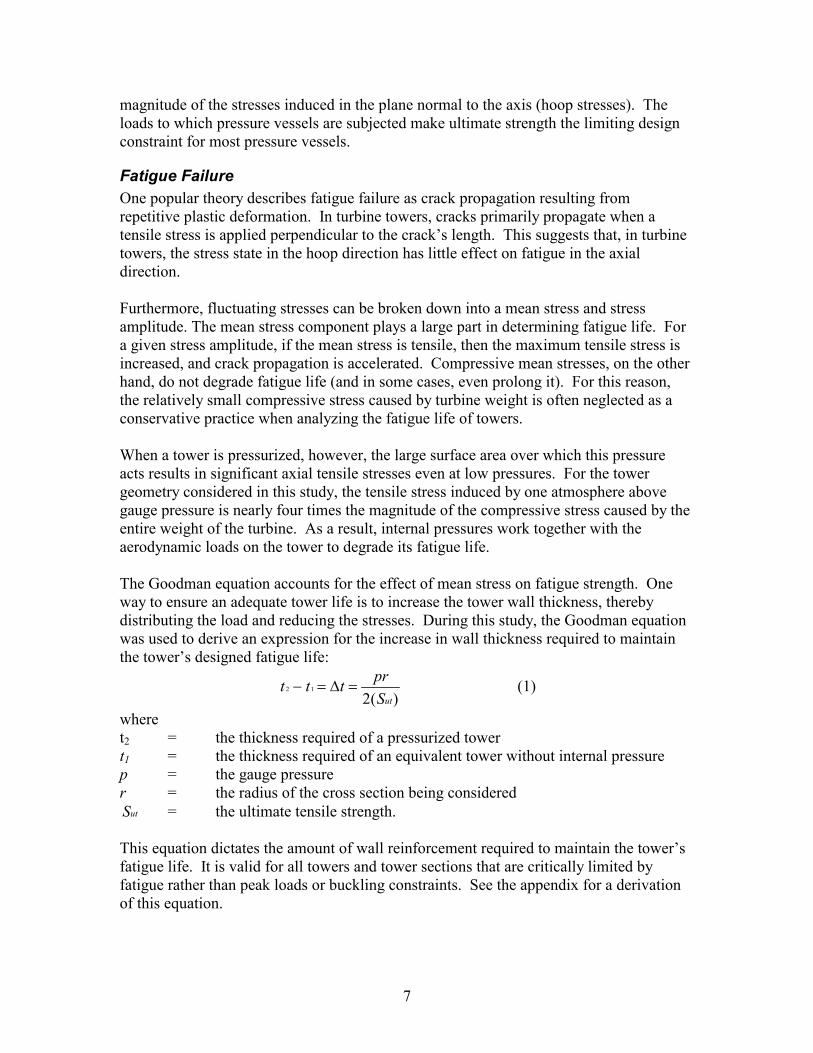
Fatigue Failure One popular theory describes fatigue failure as crack propagation resulting from repetitive plastic deformation. In turbine towers, cracks primarily propagate when a tensile stress is applied perpendicular to the crack’s length. This suggests that, in turbine towers, the stress state in the hoop direction has little effect on fatigue in the axial direction. Furthermore, fluctuating stresses can be broken down into a mean stress and stress amplitude. The mean stress component plays a large part in determining fatigue life. For a given stress amplitude, if the mean stress is tensile, then the maximum tensile stress is increased, and crack propagation is accelerated. Compressive mean stresses, on the other hand, do not degrade fatigue life (and in some cases, even prolong it). For this reason, the relatively small compressive stress caused by turbine weight is often neglected as a conservative practice when analyzing the fatigue life of towers. When a tower is pressurized, however, the large surface area over which this pressure acts results in significant axial tensile stresses even at low pressures. For the tower geometry considered in this study, the tensile stress induced by one atmosphere above gauge pressure is nearly four times the magnitude of the compressive stress caused by the entire weight of the turbine. As a result, internal pressures work together with the aerodynamic loads on the tower to degrade its fatigue life. The Goodman equation accounts for the effect of mean stress on fatigue strength. One way to ensure an adequate tower life is to increase the tower wall thickness, thereby distributing the load and reducing the stresses. During this study, the Goodman equation was used to derive an expression for the increase in wall thickness required to maintain the tower’s designed fatigue life:
)(212
utSprttt =∆=− (1)
where t2 = the thickness required of a pressurized tower t1 = the thickness required of an equivalent tower without internal pressure p = the gauge pressure r = the radius of the cross section being considered
utS = the ultimate tensile strength. This equation dictates the amount of wall reinforcement required to maintain the tower’s fatigue life. It is valid for all towers and tower sections that are critically limited by fatigue rather than peak loads or buckling constraints. See the appendix for a derivation of this equation.
8
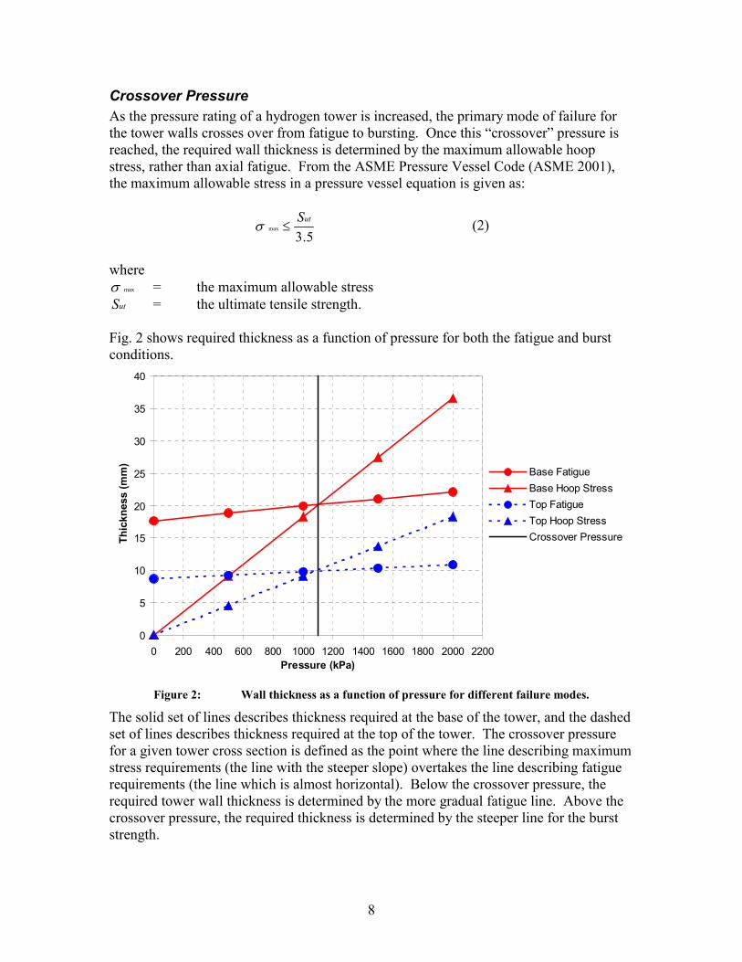
Crossover Pressure As the pressure rating of a hydrogen tower is increased, the primary mode of failure for the tower walls crosses over from fatigue to bursting. Once this “crossover” pressure is reached, the required wall thickness is determined by the maximum allowable hoop stress, rather than axial fatigue. From the ASME Pressure Vessel Code (ASME 2001), the maximum allowable stress in a pressure vessel equation is given as:
5.3max
utS≤σ (2)
where
maxσ = the maximum allowable stress utS = the ultimate tensile strength.
Fig. 2 shows required thickness as a function of pressure for both the fatigue and burst conditions.
0
5
10
15
20
25
30
35
40
0 200 400 600 800 1000 1200 1400 1600 1800 2000 2200Pressure (kPa)
Thic
knes
s (m
m)
Base FatigueBase Hoop StressTop FatigueTop Hoop StressCrossover Pressure
Figure 2: Wall thickness as a function of pressure for different failure modes.
The solid set of lines describes thickness required at the base of the tower, and the dashed set of lines describes thickness required at the top of the tower. The crossover pressure for a given tower cross section is defined as the point where the line describing maximum stress requirements (the line with the steeper slope) overtakes the line describing fatigue requirements (the line which is almost horizontal). Below the crossover pressure, the required tower wall thickness is determined by the more gradual fatigue line. Above the crossover pressure, the required thickness is determined by the steeper line for the burst strength.
9
Solving for the crossover pressure (the intersection of a hoop stress line and a fatigue line) at an arbitrary tower cross section results in the following equation:
−
=
717
)(4
1
Etd
SEp utcrossover (3)
where E = the welded joint efficiency Sut = the Ultimate Tensile Strength
1td = the diameter/thickness (d/t) ratio.
In order to be consistent with the WindPACT tower model, this study assumes that the tower is fatigue constrained at every section and has a constant d/t ratio. For these assumptions, the crossover pressure is the same at all points in the tower. This can be seen in Fig. 2 by noticing that the solid lines and dashed lines cross at the same pressure. Furthermore, this equation demonstrates that crossover pressure is dependent only on ultimate tensile strength, welded joint efficiency, and d/t ratio.
For the assumptions in this study (Sut = 636 MPa and d/t = 320), the crossover pressure is 1.1 MPa. This represents a somewhat conservative estimate of crossover pressure because the value of 320 is near the upper limit for d/t ratios. Lower d/t ratios result in a higher crossover pressure. Towers with a d/t ratio that varies with height will have different crossover pressures at different tower sections and should probably be designed to their lowest crossover pressure. Most utility-scale towers will probably have a minimum crossover pressure between 1.0 and 1.5 MPa (10-15 atm).
Another consideration is that the diameter at the top of a tower may be governed either by aesthetics or the size of the yaw bearing, rather than fatigue loads. As a result, this section may be constrained by buckling, a failure mode which is not degraded by internal pressure. These towers could contain moderate pressures without requiring any reinforcement of the wall sections that are buckling constrained.
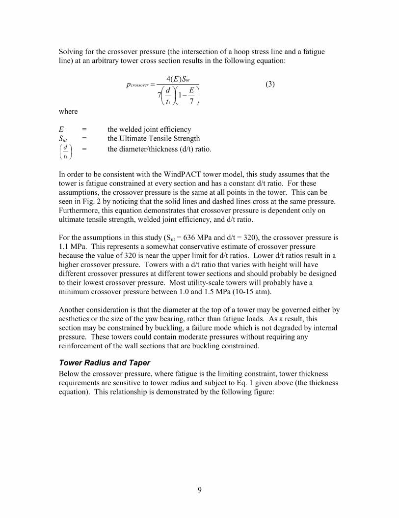
Tower Radius and Taper Below the crossover pressure, where fatigue is the limiting constraint, tower thickness requirements are sensitive to tower radius and subject to Eq. 1 given above (the thickness equation). This relationship is demonstrated by the following figure:
10
0.00
5.00
10.00
15.00
20.00
25.00
0 200 400 600 800 1000 1200Pressure (kPa)
Req
uire
d In
crea
se in
Thi
ckne
ss (m
m)
mr 41.1=
mr 12.2=
mr 82.2=
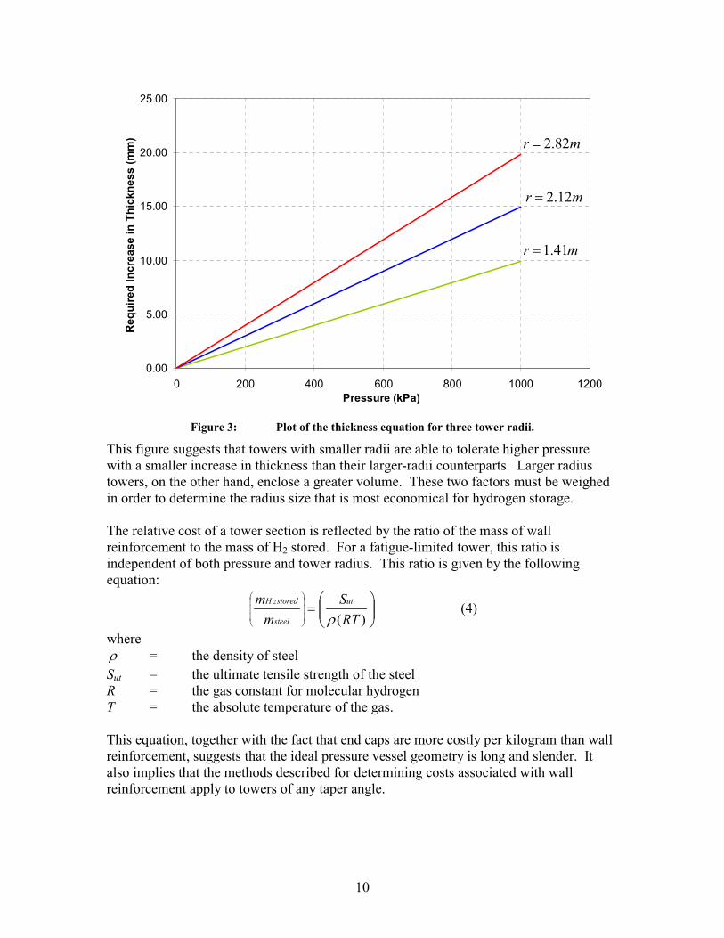
Figure 3: Plot of the thickness equation for three tower radii.
This figure suggests that towers with smaller radii are able to tolerate higher pressure with a smaller increase in thickness than their larger-radii counterparts. Larger radius towers, on the other hand, enclose a greater volume. These two factors must be weighed in order to determine the radius size that is most economical for hydrogen storage. The relative cost of a tower section is reflected by the ratio of the mass of wall reinforcement to the mass of H2 stored. For a fatigue-limited tower, this ratio is independent of both pressure and tower radius. This ratio is given by the following equation:
=
)(2
RTS
mm ut
steel
storedH
ρ (4)
where ρ = the density of steel Sut = the ultimate tensile strength of the steel R = the gas constant for molecular hydrogen T = the absolute temperature of the gas. This equation, together with the fact that end caps are more costly per kilogram than wall reinforcement, suggests that the ideal pressure vessel geometry is long and slender. It also implies that the methods described for determining costs associated with wall reinforcement apply to towers of any taper angle.
11
Design of a Hydrogen Tower This paper has, up to this point, been focused on outlining the unique considerations associated with outfitting a turbine tower for hydrogen storage. This section outlines a cost analysis and uses it as a standard to evaluate the subsequent conceptual designs.
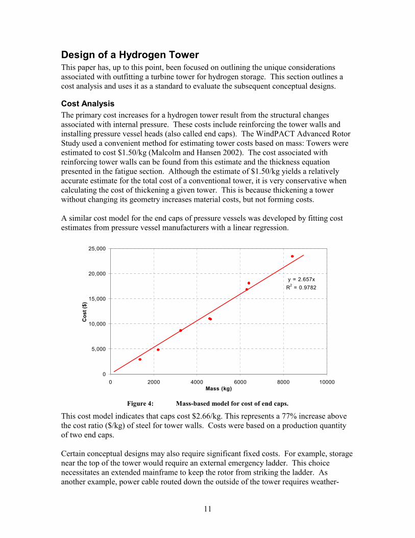
Cost Analysis The primary cost increases for a hydrogen tower result from the structural changes associated with internal pressure. These costs include reinforcing the tower walls and installing pressure vessel heads (also called end caps). The WindPACT Advanced Rotor Study used a convenient method for estimating tower costs based on mass: Towers were estimated to cost $1.50/kg (Malcolm and Hansen 2002). The cost associated with reinforcing tower walls can be found from this estimate and the thickness equation presented in the fatigue section. Although the estimate of $1.50/kg yields a relatively accurate estimate for the total cost of a conventional tower, it is very conservative when calculating the cost of thickening a given tower. This is because thickening a tower without changing its geometry increases material costs, but not forming costs. A similar cost model for the end caps of pressure vessels was developed by fitting cost estimates from pressure vessel manufacturers with a linear regression.
y = 2.657xR2 = 0.9782
0
5,000
10,000
15,000
20,000
25,000
0 2000 4000 6000 8000 10000Mass (kg)
Cos
t ($)
Figure 4: Mass-based model for cost of end caps.
This cost model indicates that caps cost $2.66/kg. This represents a 77% increase above the cost ratio ($/kg) of steel for tower walls. Costs were based on a production quantity of two end caps. Certain conceptual designs may also require significant fixed costs. For example, storage near the top of the tower would require an external emergency ladder. This choice necessitates an extended mainframe to keep the rotor from striking the ladder. As another example, power cable routed down the outside of the tower requires weather-
12
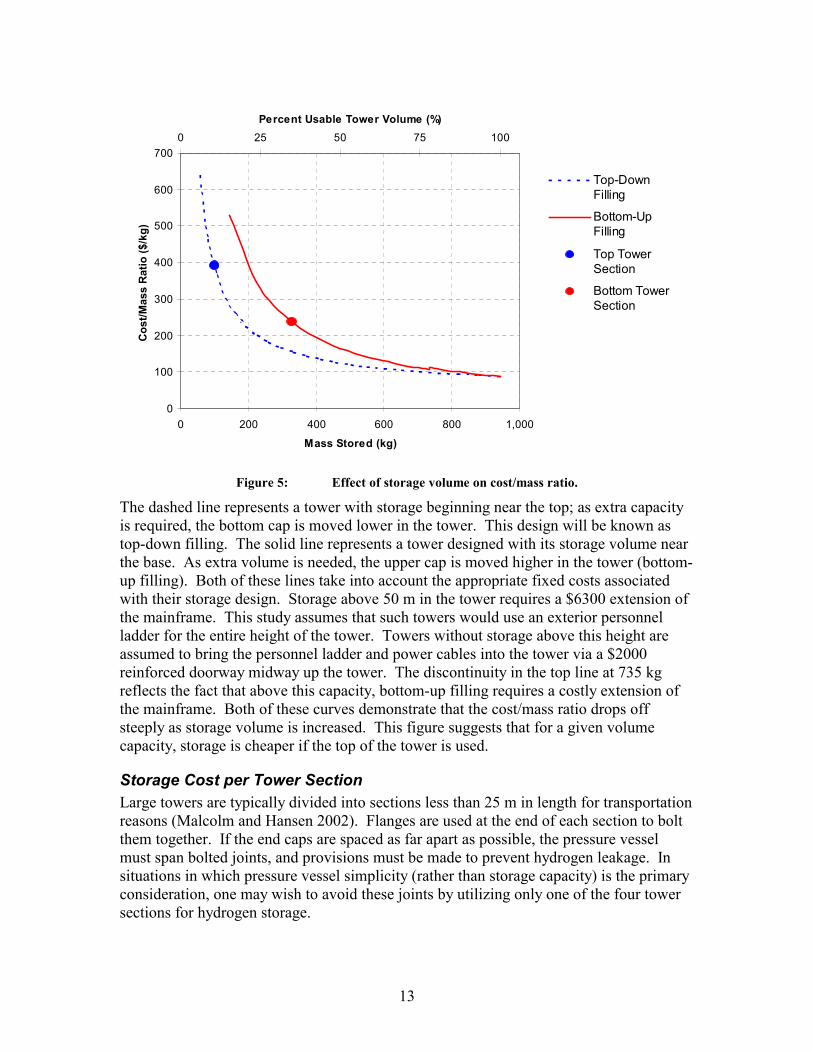
resistant conduit. The secondary costs that were considered are outlined in Table 2.
Table 2: Secondary Hydrogen Storage Costs Additional Door $ 2,000Mainframe Extension $ 6,300Ladder Cost $/m 32.8Nozzles and Manway $ 16,000Conduit $/m 35
It was assumed that an external personnel tower would require an 8” extension of the mainframe to avoid blade strikes. The cost of the mainframe extension was estimated by increasing the mainframe cost in the WindPACT study to reflect a mainframe that is 8” longer. The costs of two nozzles and one manway are lumped together into one item because they represent labor-intensive modifications to the pressure vessel shell. The additional ladder, manway, and nozzles are necessary for the periodic purging and inspection of the pressure vessel. These costs are modeled with a fixed base that rises linearly with pressure. Other additional costs were estimated by obtaining data from industry. Unless otherwise stated, these secondary costs are included wherever applicable in the following cost analysis.
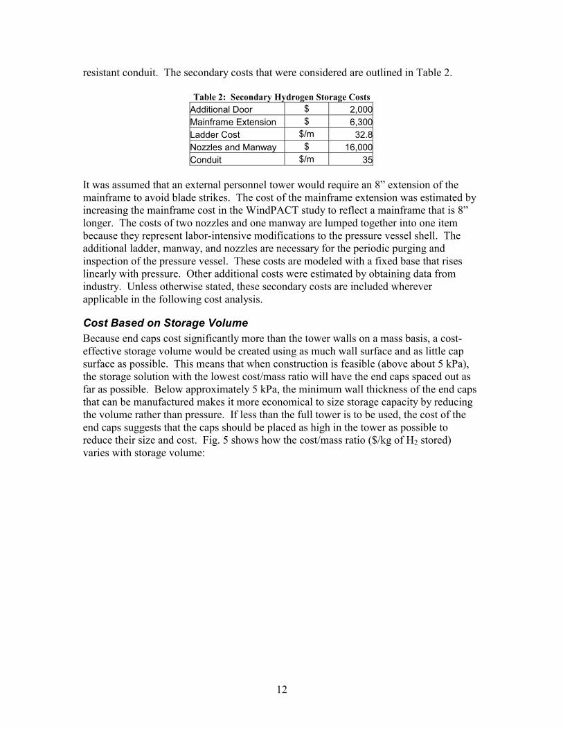
Cost Based on Storage Volume Because end caps cost significantly more than the tower walls on a mass basis, a cost-effective storage volume would be created using as much wall surface and as little cap surface as possible. This means that when construction is feasible (above about 5 kPa), the storage solution with the lowest cost/mass ratio will have the end caps spaced out as far as possible. Below approximately 5 kPa, the minimum wall thickness of the end caps that can be manufactured makes it more economical to size storage capacity by reducing the volume rather than pressure. If less than the full tower is to be used, the cost of the end caps suggests that the caps should be placed as high in the tower as possible to reduce their size and cost. Fig. 5 shows how the cost/mass ratio ($/kg of H2 stored) varies with storage volume:
13
0
100
200
300
400
500
600
700
0 200 400 600 800 1,000
Mass Stored (kg)
Cos
t/Mas
s R
atio
($/k
g)0 25 50 75 100
Percent Usable Tower Volume (%)
Top-DownFilling
Bottom-UpFilling
Top TowerSection
Bottom TowerSection
Figure 5: Effect of storage volume on cost/mass ratio.
The dashed line represents a tower with storage beginning near the top; as extra capacity is required, the bottom cap is moved lower in the tower. This design will be known as top-down filling. The solid line represents a tower designed with its storage volume near the base. As extra volume is needed, the upper cap is moved higher in the tower (bottom-up filling). Both of these lines take into account the appropriate fixed costs associated with their storage design. Storage above 50 m in the tower requires a $6300 extension of the mainframe. This study assumes that such towers would use an exterior personnel ladder for the entire height of the tower. Towers without storage above this height are assumed to bring the personnel ladder and power cables into the tower via a $2000 reinforced doorway midway up the tower. The discontinuity in the top line at 735 kg reflects the fact that above this capacity, bottom-up filling requires a costly extension of the mainframe. Both of these curves demonstrate that the cost/mass ratio drops off steeply as storage volume is increased. This figure suggests that for a given volume capacity, storage is cheaper if the top of the tower is used.
Storage Cost per Tower Section Large towers are typically divided into sections less than 25 m in length for transportation reasons (Malcolm and Hansen 2002). Flanges are used at the end of each section to bolt them together. If the end caps are spaced as far apart as possible, the pressure vessel must span bolted joints, and provisions must be made to prevent hydrogen leakage. In situations in which pressure vessel simplicity (rather than storage capacity) is the primary consideration, one may wish to avoid these joints by utilizing only one of the four tower sections for hydrogen storage.
14
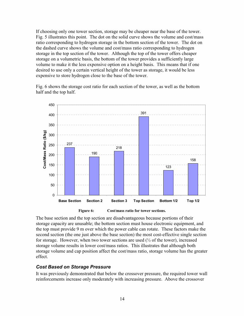
If choosing only one tower section, storage may be cheaper near the base of the tower. Fig. 5 illustrates this point. The dot on the solid curve shows the volume and cost/mass ratio corresponding to hydrogen storage in the bottom section of the tower. The dot on the dashed curve shows the volume and cost/mass ratio corresponding to hydrogen storage in the top section of the tower. Although the top of the tower offers cheaper storage on a volumetric basis, the bottom of the tower provides a sufficiently large volume to make it the less expensive option on a height basis. This means that if one desired to use only a certain vertical height of the tower as storage, it would be less expensive to store hydrogen close to the base of the tower. Fig. 6 shows the storage cost ratio for each section of the tower, as well as the bottom half and the top half.
237
190218
391
123
158
0
50
100
150
200
250
300
350
400
450
Base Section Section 2 Section 3 Top Section Bottom 1/2 Top 1/2
Cos
t/Mas
s R
atio
($/k
g)
Figure 6: Cost/mass ratio for tower sections.
The base section and the top section are disadvantageous because portions of their storage capacity are unusable; the bottom section must house electronic equipment, and the top must provide 9 m over which the power cable can rotate. These factors make the second section (the one just above the base section) the most cost-effective single section for storage. However, when two tower sections are used (½ of the tower), increased storage volume results in lower cost/mass ratios. This illustrates that although both storage volume and cap position affect the cost/mass ratio, storage volume has the greater effect.
Cost Based on Storage Pressure It was previously demonstrated that below the crossover pressure, the required tower wall reinforcements increase only moderately with increasing pressure. Above the crossover
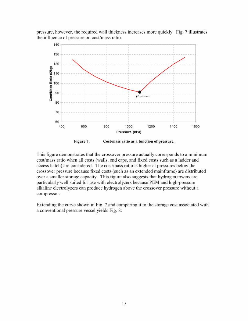
15
pressure, however, the required wall thickness increases more quickly. Fig. 7 illustrates the influence of pressure on cost/mass ratio.
60
70
80
90
100
110
120
130
140
400 600 800 1000 1200 1400 1600
Pressure (kPa)
Cos
t/Mas
s R
atio
($/k
g)
crossoverp
Figure 7: Cost/mass ratio as a function of pressure.
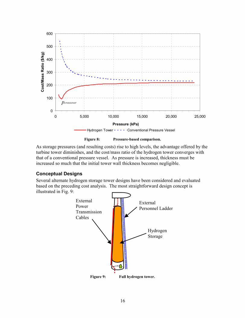
This figure demonstrates that the crossover pressure actually corresponds to a minimum cost/mass ratio when all costs (walls, end caps, and fixed costs such as a ladder and access hatch) are considered. The cost/mass ratio is higher at pressures below the crossover pressure because fixed costs (such as an extended mainframe) are distributed over a smaller storage capacity. This figure also suggests that hydrogen towers are particularly well suited for use with electrolyzers because PEM and high-pressure alkaline electrolyzers can produce hydrogen above the crossover pressure without a compressor. Extending the curve shown in Fig. 7 and comparing it to the storage cost associated with a conventional pressure vessel yields Fig. 8:
16
0
100
200
300
400
500
600
0 5,000 10,000 15,000 20,000 25,000
Pressure (kPa)
Cos
t/Mas
s R
atio
($/k
g)
Hydrogen Tower Conventional Pressure Vessel
crossoverp
Figure 8: Pressure-based comparison.
As storage pressures (and resulting costs) rise to high levels, the advantage offered by the turbine tower diminishes, and the cost/mass ratio of the hydrogen tower converges with that of a conventional pressure vessel. As pressure is increased, thickness must be increased so much that the initial tower wall thickness becomes negligible.
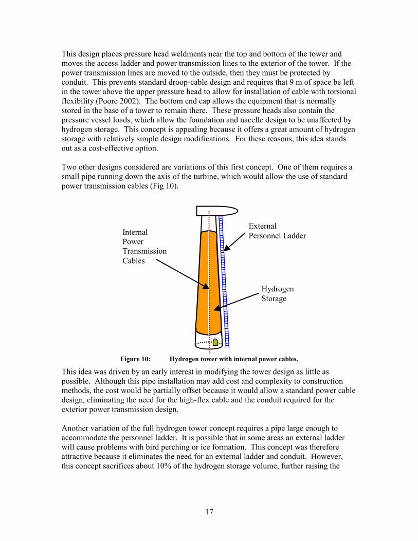
Conceptual Designs Several alternate hydrogen storage tower designs have been considered and evaluated based on the preceding cost analysis. The most straightforward design concept is illustrated in Fig. 9:
Figure 9: Full hydrogen tower.
External Personnel Ladder
Hydrogen Storage
External Power Transmission Cables
17
This design places pressure head weldments near the top and bottom of the tower and moves the access ladder and power transmission lines to the exterior of the tower. If the power transmission lines are moved to the outside, then they must be protected by conduit. This prevents standard droop-cable design and requires that 9 m of space be left in the tower above the upper pressure head to allow for installation of cable with torsional flexibility (Poore 2002). The bottom end cap allows the equipment that is normally stored in the base of a tower to remain there. These pressure heads also contain the pressure vessel loads, which allow the foundation and nacelle design to be unaffected by hydrogen storage. This concept is appealing because it offers a great amount of hydrogen storage with relatively simple design modifications. For these reasons, this idea stands out as a cost-effective option. Two other designs considered are variations of this first concept. One of them requires a small pipe running down the axis of the turbine, which would allow the use of standard power transmission cables (Fig 10).
Figure 10: Hydrogen tower with internal power cables.
This idea was driven by an early interest in modifying the tower design as little as possible. Although this pipe installation may add cost and complexity to construction methods, the cost would be partially offset because it would allow a standard power cable design, eliminating the need for the high-flex cable and the conduit required for the exterior power transmission design. Another variation of the full hydrogen tower concept requires a pipe large enough to accommodate the personnel ladder. It is possible that in some areas an external ladder will cause problems with bird perching or ice formation. This concept was therefore attractive because it eliminates the need for an external ladder and conduit. However, this concept sacrifices about 10% of the hydrogen storage volume, further raising the
External Personnel Ladder Internal
Power Transmission Cables
Hydrogen Storage

cost/mass ratio. The added cost and construction complexity of the large diameter pipe makes this concept less attractive than other options. It was therefore excluded from further consideration. The significant cost associated with the bottom end cap motivated yet another design concept. Instead of manufacturing the large bottom end cap, a thin plate could be welded flush with the bottom of the tower. This plate acts as a seal but isn’t designed to bear a load. The pressure load would be borne by the foundation and the flange bolts at the base of the tower (Fig. 11).
Figure 11: Hydrogen tower, alternate foundation design.
This concept offers marginally greater hydrogen storage capacity but creates a large bending moment on the foundation. The pressurized hydrogen pushes down in the middle of the foundation, and the pre-stressed bolts pull up around the foundation’s perimeter. Also, the power electronics and wind turbine control equipment normally stored in the base of the tower would have to be stored elsewhere (either in a building adjacent to the tower’s base or in the nacelle). If, in the future, hydrogen towers become a part of the energy economy, this foundation concept would be a good subject for further study.
Foundation
Hydrogen Storage Bolts
Base Flange
18
19
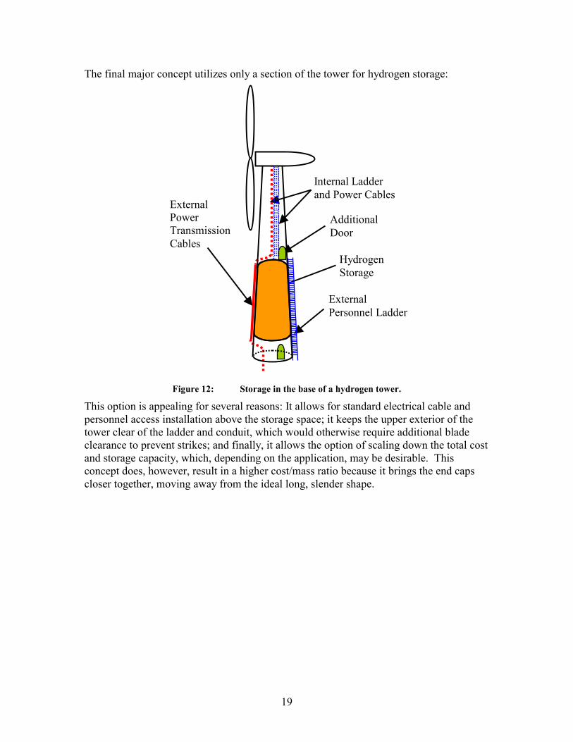
The final major concept utilizes only a section of the tower for hydrogen storage:
Figure 12: Storage in the base of a hydrogen tower.
This option is appealing for several reasons: It allows for standard electrical cable and personnel access installation above the storage space; it keeps the upper exterior of the tower clear of the ladder and conduit, which would otherwise require additional blade clearance to prevent strikes; and finally, it allows the option of scaling down the total cost and storage capacity, which, depending on the application, may be desirable. This concept does, however, result in a higher cost/mass ratio because it brings the end caps closer together, moving away from the ideal long, slender shape.
External Personnel Ladder
External Power Transmission Cables
Hydrogen Storage
Internal Ladder and Power Cables
Additional Door
20
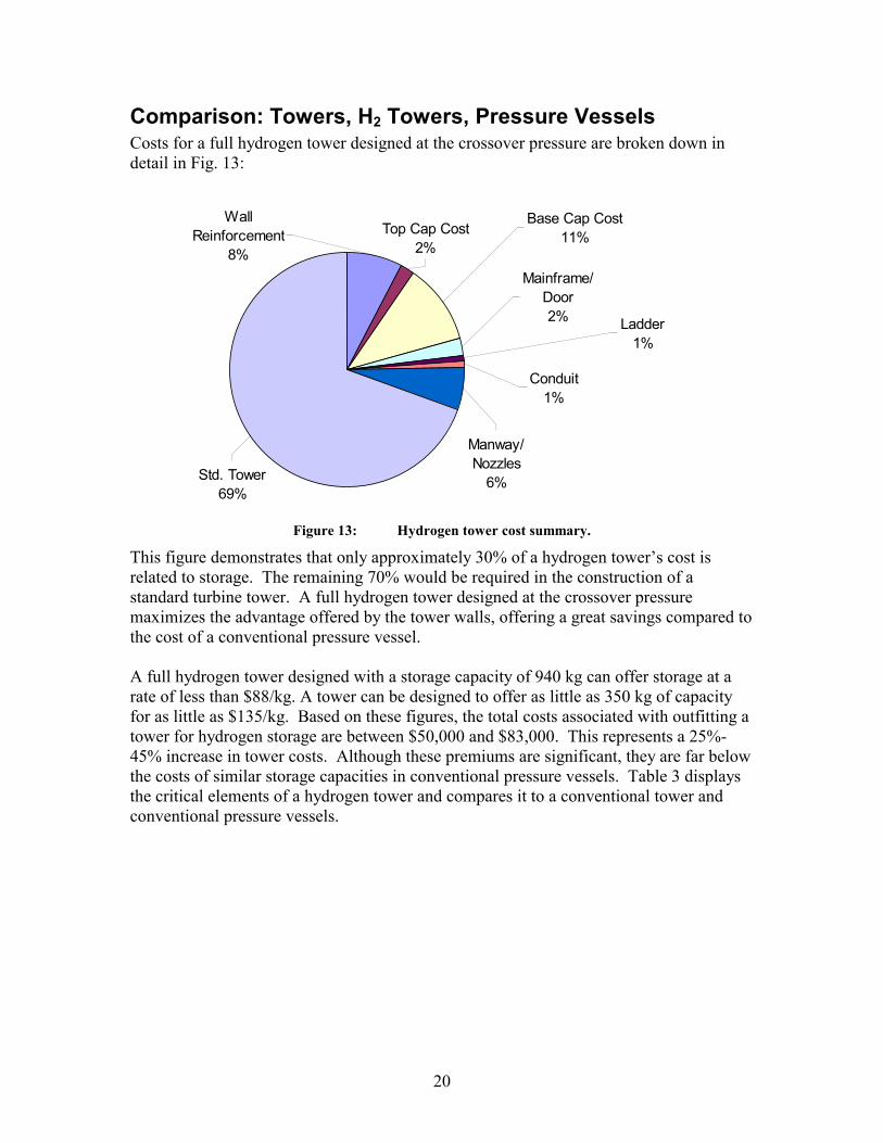
Comparison: Towers, H2 Towers, Pressure Vessels Costs for a full hydrogen tower designed at the crossover pressure are broken down in detail in Fig. 13:
Std. Tower69%
Top Cap Cost2%
Base Cap Cost11%
Mainframe/ Door2% Ladder
1%
Conduit1%
Manway/ Nozzles
6%
Wall Reinforcement
8%
Figure 13: Hydrogen tower cost summary.
This figure demonstrates that only approximately 30% of a hydrogen tower’s cost is related to storage. The remaining 70% would be required in the construction of a standard turbine tower. A full hydrogen tower designed at the crossover pressure maximizes the advantage offered by the tower walls, offering a great savings compared to the cost of a conventional pressure vessel. A full hydrogen tower designed with a storage capacity of 940 kg can offer storage at a rate of less than $88/kg. A tower can be designed to offer as little as 350 kg of capacity for as little as $135/kg. Based on these figures, the total costs associated with outfitting a tower for hydrogen storage are between $50,000 and $83,000. This represents a 25%-45% increase in tower costs. Although these premiums are significant, they are far below the costs of similar storage capacities in conventional pressure vessels. Table 3 displays the critical elements of a hydrogen tower and compares it to a conventional tower and conventional pressure vessels.
21
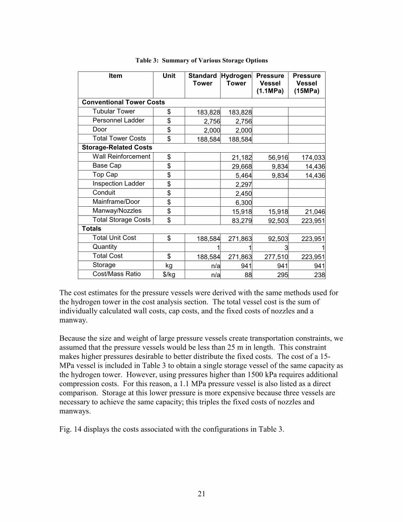
Table 3: Summary of Various Storage Options
Item Unit Standard
Tower Hydrogen
Tower Pressure Vessel
(1.1MPa)
Pressure Vessel
(15MPa) Conventional Tower Costs
Tubular Tower $ 183,828 183,828 Personnel Ladder $ 2,756 2,756 Door $ 2,000 2,000 Total Tower Costs $ 188,584 188,584
Storage-Related Costs Wall Reinforcement $ 21,182 56,916 174,033Base Cap $ 29,668 9,834 14,436Top Cap $ 5,464 9,834 14,436Inspection Ladder $ 2,297 Conduit $ 2,450 Mainframe/Door $ 6,300 Manway/Nozzles $ 15,918 15,918 21,046Total Storage Costs $ 83,279 92,503 223,951
Totals Total Unit Cost $ 188,584 271,863 92,503 223,951Quantity 1 1 3 1Total Cost $ 188,584 271,863 277,510 223,951Storage kg n/a 941 941 941Cost/Mass Ratio $/kg n/a 88 295 238
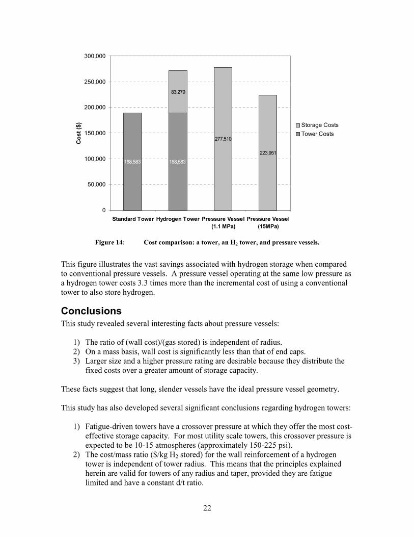
The cost estimates for the pressure vessels were derived with the same methods used for the hydrogen tower in the cost analysis section. The total vessel cost is the sum of individually calculated wall costs, cap costs, and the fixed costs of nozzles and a manway. Because the size and weight of large pressure vessels create transportation constraints, we assumed that the pressure vessels would be less than 25 m in length. This constraint makes higher pressures desirable to better distribute the fixed costs. The cost of a 15-MPa vessel is included in Table 3 to obtain a single storage vessel of the same capacity as the hydrogen tower. However, using pressures higher than 1500 kPa requires additional compression costs. For this reason, a 1.1 MPa pressure vessel is also listed as a direct comparison. Storage at this lower pressure is more expensive because three vessels are necessary to achieve the same capacity; this triples the fixed costs of nozzles and manways. Fig. 14 displays the costs associated with the configurations in Table 3.
22
188,583 188,583
83,279
277,510
223,951
0
50,000
100,000
150,000
200,000
250,000
300,000
Standard Tower Hydrogen Tower Pressure Vessel(1.1 MPa)
Pressure Vessel(15MPa)
Cos
t ($) Storage Costs
Tower Costs
Figure 14: Cost comparison: a tower, an H2 tower, and pressure vessels.
This figure illustrates the vast savings associated with hydrogen storage when compared to conventional pressure vessels. A pressure vessel operating at the same low pressure as a hydrogen tower costs 3.3 times more than the incremental cost of using a conventional tower to also store hydrogen.
Conclusions This study revealed several interesting facts about pressure vessels:
1) The ratio of (wall cost)/(gas stored) is independent of radius. 2) On a mass basis, wall cost is significantly less than that of end caps. 3) Larger size and a higher pressure rating are desirable because they distribute the
fixed costs over a greater amount of storage capacity. These facts suggest that long, slender vessels have the ideal pressure vessel geometry. This study has also developed several significant conclusions regarding hydrogen towers:
1) Fatigue-driven towers have a crossover pressure at which they offer the most cost-effective storage capacity. For most utility scale towers, this crossover pressure is expected to be 10-15 atmospheres (approximately 150-225 psi).
2) The cost/mass ratio ($/kg H2 stored) for the wall reinforcement of a hydrogen tower is independent of tower radius. This means that the principles explained herein are valid for towers of any radius and taper, provided they are fatigue limited and have a constant d/t ratio.

23
3) Towers with a varying d/t ratio can still offer affordable storage, but they will probably be most economical if designed to their lowest crossover pressure (which occurs at the section with the largest d/t ratio).
This study describes general design guidelines for a cost-effective hydrogen tower:
1) A hydrogen tower should use as much of the tower’s volume as possible for hydrogen storage.
2) Towers should be designed to store hydrogen at the crossover pressure. 3) If it is most important that the pressure vessel be designed to a certain height,
storage should be placed as low in the tower as possible. 4) If, on the other hand, it is more important that the pressure vessel must be of a
desired volume, storage should be put as high in the tower as possible. A hydrogen tower designed with a storage capacity of 940 kg adds an additional $83,000 to the cost of the wind turbine tower and offers storage at a rate of $88/kg. Although these premiums are significant, the pressure vessel model in this paper predicts storage that is 3.3 times more expensive than storage in a hydrogen tower. A qualitative explanation for this tremendous cost saving is that the wind turbine tower is a very long, slender tube, which approaches the ideal geometry for a pressure vessel. The primary cost of an ideal vessel is associated with the long walls. Hydrogen towers result in major savings because it is very inexpensive to reinforce the walls of a conventional tower if the storage pressure is below the crossover pressure.
Future Work This study highlighted the need for future work in several areas. A survey of the literature shows that there is room for further study of the effects of HE as it pertains to hydrogen handling. HE is a subject that must be thoroughly investigated if the hydrogen economy is to make progress. Another area of further research lies in foundation design. Because the bottom end cap in a hydrogen tower costs more than $30,000, it would be valuable to investigate the potential cost benefit of using the foundation to bear this load. This consideration will become more valuable if hydrogen towers gain popular use and acceptance. From a review of the literature, it is clear that there is a relative lack of reliable information regarding the cost of above ground pressure vessel storage. We collected industry quotes on pressure vessel prices that were 2-5 times lower than the costs most commonly sited in the literature. Discrepancies of this magnitude will severely handicap the future of the hydrogen energy economy. There is therefore an urgent need for new and detailed studies regarding the costs associated with hydrogen storage methods. Finally, when considering the construction of a hydrogen tower, one must consider whether the value of having hydrogen at the turbine tower justifies the cost premiums

24
associated with hydrogen storage. The value of storing hydrogen is currently being evaluated in a larger economic context at NREL as part of the WindSTORM study.
25
References ASME Boiler and Pressure Vessel Code. (2001). New York, NY: The American Society of Mechanical Engineers. Bain, A.; Barclay, J.; Bose, T.; Edeskuty, F.; Fairlie, M.; Hansel, J.; Hay, D.; Swain, M.; Ohi, J.; Gregoire Padro, C. (1998). Sourcebook for Hydrogen Applications. Quebec, Canada: Hydrogen Research Institute; Golden, CO: National Renewable Energy Laboratory; NREL/BK-540-24778.
Cox, K. E.; Williamson Jr., K.D. eds. (1977). Transmission and Storage. Hydrogen: Its Technology and Implications, Vol. II, Cleveland: CRC Press.
Fingersh, L. J. (2003). Optimized Hydrogen and Electricity Generation from Wind. NREL/TP-500-34364. Golden, CO: National Renewable Energy Laboratory.
Gray, H.R. (1974). “Hydrogen Environment Embrittlement: Experimental Variables.” Hydrogen Embrittlement Testing. pp. 133-151. Proceedings from the 75th Annual Meeting of the American Society for Testing and Materials; 25-30 June 1972, Los Angeles, CA; Baltimore, MD: ASTM.
Malcolm, D.J.; Hansen, A.C. (2002), WindPACT Turbine Rotor Design Study. NREL/SR-500-32495. Work performed by Global Energy Concepts, LLC, Kirkland, Washington. Golden, CO: National Renewable Energy Laboratory.
Mohitpour, M.; Golshan, H.; Murray, A. (2000). Pipeline Design & Construction: A Practical Approach. New York: ASME Press.
Poore, R.; Lettenmaier, T. (2002). Alternative Design Study Report: WindPACT Advanced Wind Turbine Drive Train Designs Study. NREL/SR-500-33196. Work performed by Global Energy Concepts, LLC, Kirkland, Washington. Golden, CO: National Renewable Energy Laboratory.
Roberge, P. (1999). Handbook of Corrosion Engineering. New York: McGraw-Hill.

26
Further Reading Boyer, H.E., ed. (1986). Atlas of Fatigue Curves. Metals Park, Ohio: American Society for Metals.
Code of Practice for Fatigue Design and Assessment of Steel Structures. (1993). Paramus, NJ: ILI for the British Standards Institute.
Craig Jr., R.R. (2000). Mechanics of Materials. New York: John Wiley & Sons. Fullenwider, M.A. (1983). Hydrogen Entry and Action in Metals. New York: Pergamon Press.
Hoover, W.R.; Robinson, S.L.; Stoltz, R.E.; Springarn, J.R. (1981). “Hydrogen Compatibility of Structural Materials for Energy Storage and Transmission: Final Report.” Livermore, CA: Sandia National Laboratories.
Interrante, C.G. (1982). “Basic Aspects of the Problems of Hydrogen in Steels.” Metals Park, Ohio: American Society for Metals.
Juvinall, R.C., Marshek, K.M. (1983). Fundamentals of Machine Component Design. New York: John Wiley & Sons.
McCarty, Robert D. (1975). Hydrogen Properties. Hydrogen: Its Technology and Implications, Vol. III, Cleveland: CRC Press.
Mohitpour, M.; Pierce, C.; Hooper, R. (1988). “The Design and Engineering of Cross Country Hydrogen Pipelines.” ASME Journal of Energy Resources Technology, Vol. 110, pp. 203-207.
Rice, R.C., et al., eds. (1988). Fatigue Design Handbook. Warrendale, PA: Society of Automotive Engineers.
Shigley, J.E., Mischke, C.R. (1963). Mechanical Engineering Design. New York: McGraw-Hill.
Structural Welding Code: Steel. (1979). Miami, FL: American Welding Society. Wipf, H., ed. (1997). Hydrogen in Metals III: Properties and Applications. Topics in Applied Physics, Vol. 73, Berlin: Springer.
27
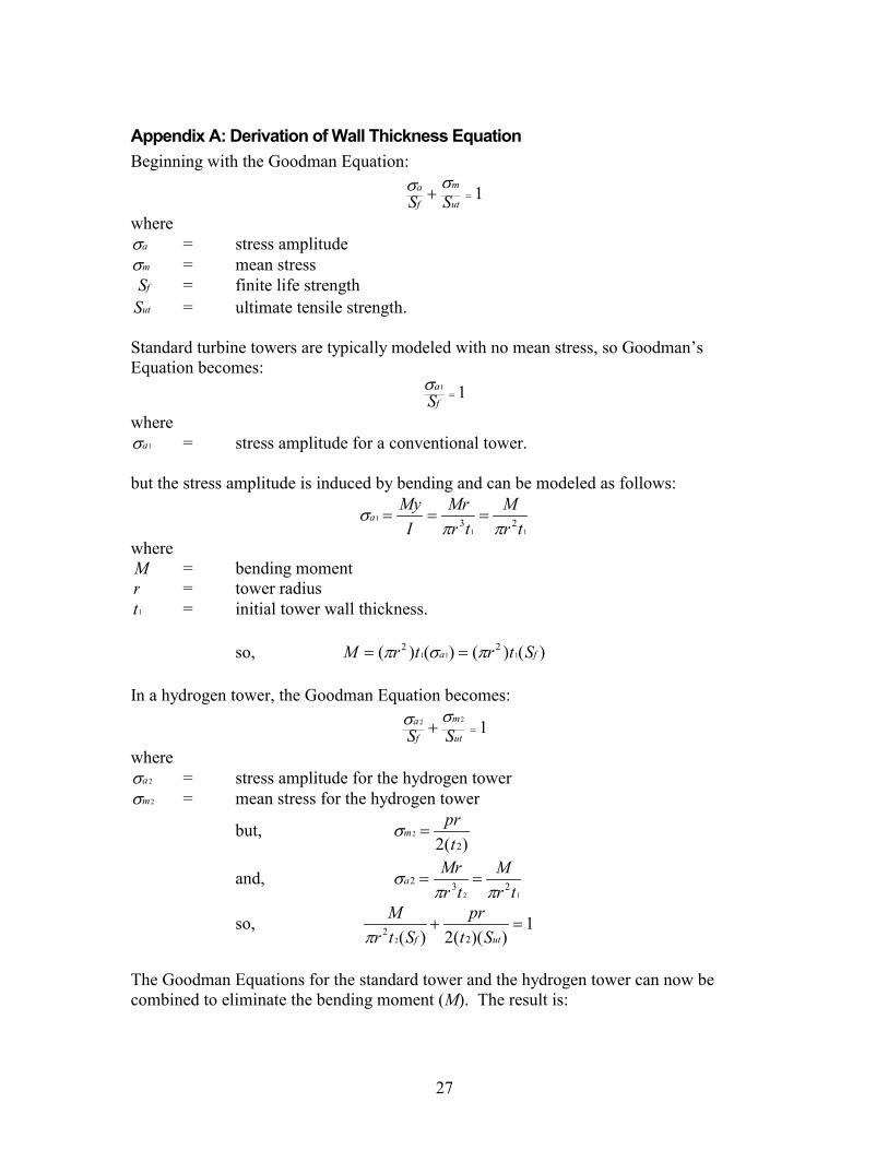
Appendix A: Derivation of Wall Thickness Equation Beginning with the Goodman Equation:
1=+ut
m
f
a
SSσσ
where aσ = stress amplitude mσ = mean stress
fS = finite life strength utS = ultimate tensile strength.
Standard turbine towers are typically modeled with no mean stress, so Goodman’s Equation becomes:
11=
f
a
Sσ
where 1aσ = stress amplitude for a conventional tower.
but the stress amplitude is induced by bending and can be modeled as follows:
11
1 23 trM
trMr
IMy
aππ
σ ===
where M = bending moment r = tower radius
1t = initial tower wall thickness. so, )()()()( 111
22fa StrtrM πσπ ==
In a hydrogen tower, the Goodman Equation becomes:
122=+
ut
m
f
a
SSσσ
where 2aσ = stress amplitude for the hydrogen tower 2mσ = mean stress for the hydrogen tower
but, )(2 2
2
tpr
m =σ
and, 12
232tr
Mtr
Mra
ππσ ==
so, 1))((2)( 2
22
=+utf St
prStr
Mπ
The Goodman Equations for the standard tower and the hydrogen tower can now be combined to eliminate the bending moment (M). The result is:
28
1))((2))(())((
22
1
2
2
=+utf
f
Stpr
StrStr
ππ
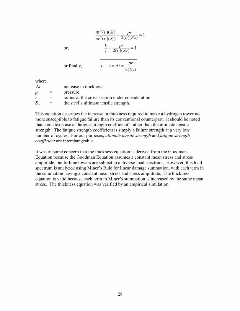
or, 1))((2 22
1=+
utStpr
tt
or finally, )(2
12
utSprttt =∆=−
where
t∆ = increase in thickness p = pressure r = radius at the cross section under consideration Sut = the steel’s ultimate tensile strength. This equation describes the increase in thickness required to make a hydrogen tower no more susceptible to fatigue failure than its conventional counterpart. It should be noted that some texts use a “fatigue strength coefficient” rather than the ultimate tensile strength. The fatigue strength coefficient is simply a failure strength at a very low number of cycles. For our purposes, ultimate tensile strength and fatigue strength coefficient are interchangeable. It was of some concern that the thickness equation is derived from the Goodman Equation because the Goodman Equation assumes a constant mean stress and stress amplitude, but turbine towers are subject to a diverse load spectrum. However, this load spectrum is analyzed using Miner’s Rule for linear damage summation, with each term in the summation having a constant mean stress and stress amplitude. The thickness equation is valid because each term in Miner’s summation is increased by the same mean stress. The thickness equation was verified by an empirical simulation.
29
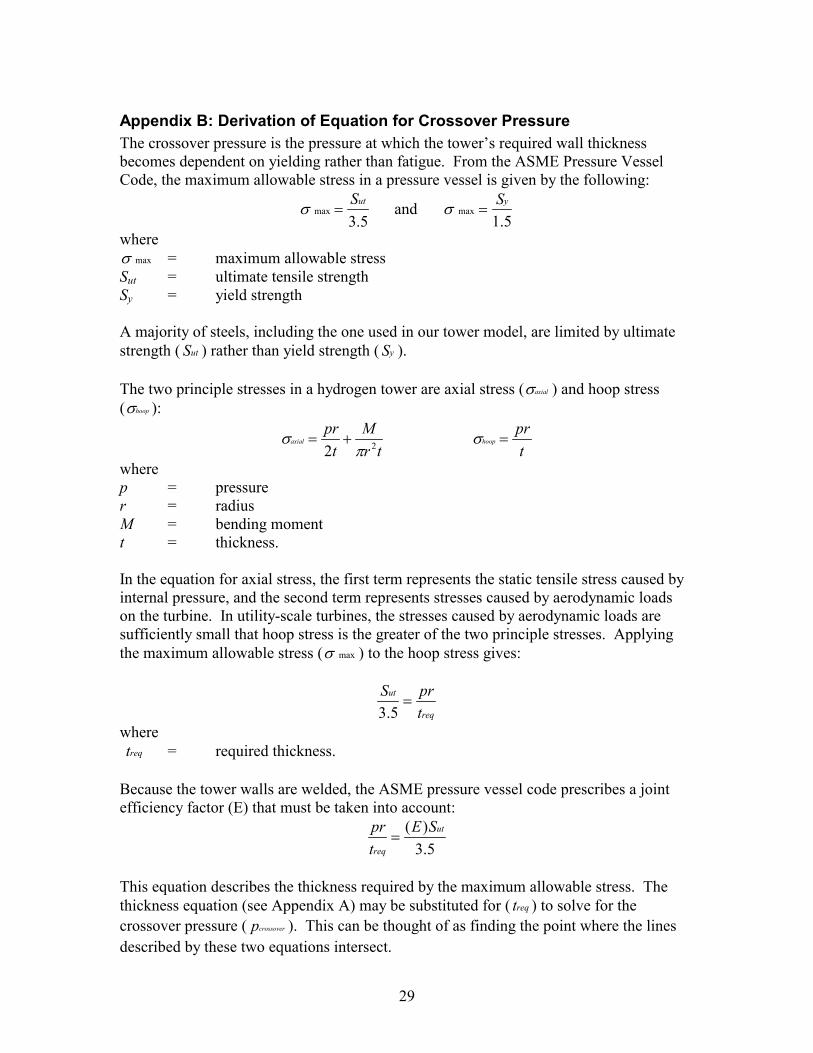
Appendix B: Derivation of Equation for Crossover Pressure The crossover pressure is the pressure at which the tower’s required wall thickness becomes dependent on yielding rather than fatigue. From the ASME Pressure Vessel Code, the maximum allowable stress in a pressure vessel is given by the following:
5.3max
utS=σ and
5.1max
yS=σ
where maxσ = maximum allowable stress
Sut = ultimate tensile strength Sy = yield strength A majority of steels, including the one used in our tower model, are limited by ultimate strength ( utS ) rather than yield strength ( yS ). The two principle stresses in a hydrogen tower are axial stress ( axialσ ) and hoop stress ( hoopσ ):
trM
tpr
axial 22 πσ +=
tpr
hoop =σ
where p = pressure r = radius M = bending moment t = thickness. In the equation for axial stress, the first term represents the static tensile stress caused by internal pressure, and the second term represents stresses caused by aerodynamic loads on the turbine. In utility-scale turbines, the stresses caused by aerodynamic loads are sufficiently small that hoop stress is the greater of the two principle stresses. Applying the maximum allowable stress ( maxσ ) to the hoop stress gives:
req
ut
tprS
=5.3
where reqt = required thickness. Because the tower walls are welded, the ASME pressure vessel code prescribes a joint efficiency factor (E) that must be taken into account:
5.3)( ut
req
SEtpr
=
This equation describes the thickness required by the maximum allowable stress. The thickness equation (see Appendix A) may be substituted for ( reqt ) to solve for the crossover pressure ( crossoverp ). This can be thought of as finding the point where the lines described by these two equations intersect.
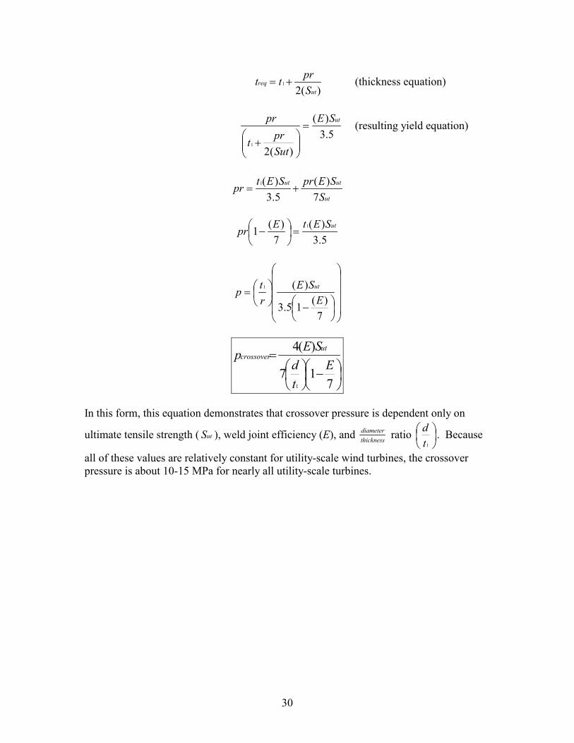
30
)(21
utreq
Sprtt += (thickness equation)
5.3
)(
)(21
utSE
Sutprt
pr=
+
(resulting yield equation)
ut
utut
SSEprSEtpr
7)(
5.3)(1
+=
5.3)(
7)(1 1 utSEtEpr =
−
−
=
7)(15.3
)(1
ESE
rtp ut
−
=
717
)(4
1
Etd
SEp utcrossover
In this form, this equation demonstrates that crossover pressure is dependent only on
ultimate tensile strength ( utS ), weld joint efficiency (E), and thicknessdiameter ratio
1td . Because
all of these values are relatively constant for utility-scale wind turbines, the crossover pressure is about 10-15 MPa for nearly all utility-scale turbines.
31
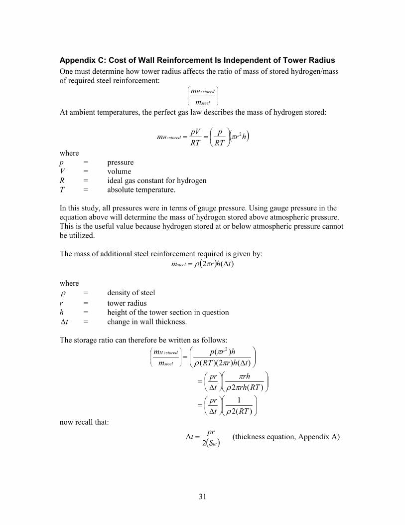
Appendix C: Cost of Wall Reinforcement Is Independent of Tower Radius One must determine how tower radius affects the ratio of mass of stored hydrogen/mass of required steel reinforcement:
steel
storedH
mm 2
At ambient temperatures, the perfect gas law describes the mass of hydrogen stored:
( )hrRTp
RTpVm storedH
22 π
==
where p = pressure V = volume R = ideal gas constant for hydrogen T = absolute temperature. In this study, all pressures were in terms of gauge pressure. Using gauge pressure in the equation above will determine the mass of hydrogen stored above atmospheric pressure. This is the useful value because hydrogen stored at or below atmospheric pressure cannot be utilized. The mass of additional steel reinforcement required is given by:
( ) )(2 thrmsteel ∆= πρ where ρ = density of steel r = tower radius h = height of the tower section in question
t∆ = change in wall thickness. The storage ratio can therefore be written as follows:
∆
=
)()2)(()( 2
2
thrRThrp
mm
steel
storedH
πρπ
∆
=)(2 RTrh
rht
prπρπ
∆
=)(2
1RTt
prρ
now recall that:
( )utSprt
2=∆ (thickness equation, Appendix A)
32
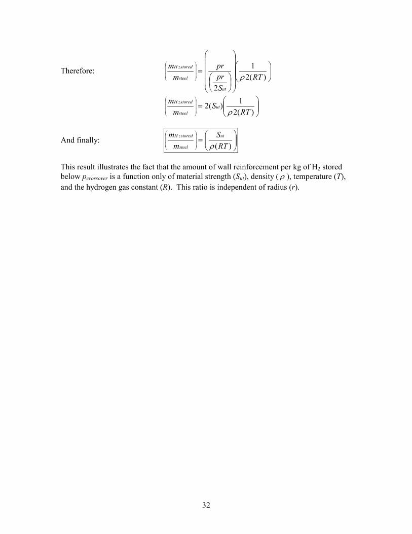
Therefore:
=
)(21
2
2
RTSprpr
mm
ut
steel
storedH
ρ
=
)(21)(22
RTS
mm
utsteel
storedH
ρ
And finally:
=
)(2
RTS
mm ut
steel
storedH
ρ
This result illustrates the fact that the amount of wall reinforcement per kg of H2 stored below pcrossover is a function only of material strength (Sut), density ( ρ ), temperature (T), and the hydrogen gas constant (R). This ratio is independent of radius (r).
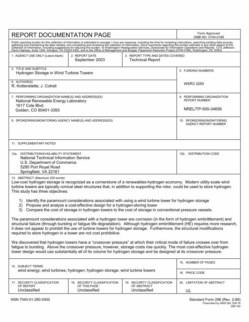
REPORT DOCUMENTATION PAGE
Form Approved OMB NO. 0704-0188
Public reporting burden for this collection of information is estimated to average 1 hour per response, including the time for reviewing instructions, searching existing data sources, gathering and maintaining the data needed, and completing and reviewing the collection of information. Send comments regarding this burden estimate or any other aspect of this collection of information, including suggestions for reducing this burden, to Washington Headquarters Services, Directorate for Information Operations and Reports, 1215 Jefferson Davis Highway, Suite 1204, Arlington, VA 22202-4302, and to the Office of Management and Budget, Paperwork Reduction Project (0704-0188), Washington, DC 20503. 1. AGENCY USE ONLY (Leave blank)
2. REPORT DATE
September 2003
3. REPORT TYPE AND DATES COVERED
Technical Report
4. TITLE AND SUBTITLE Hydrogen Storage in Wind Turbine Towers
6. AUTHOR(S) R. Kottenstette; J. Cotrell
5. FUNDING NUMBERS
WER3 3250
7. PERFORMING ORGANIZATION NAME(S) AND ADDRESS(ES)
National Renewable Energy Laboratory 1617 Cole Blvd.
Golden, CO 80401-3393
8. PERFORMING ORGANIZATION
REPORT NUMBER NREL/TP-500-34656
9. SPONSORING/MONITORING AGENCY NAME(S) AND ADDRESS(ES)
10. SPONSORING/MONITORING
AGENCY REPORT NUMBER
11. SUPPLEMENTARY NOTES
12a. DISTRIBUTION/AVAILABILITY STATEMENT
National Technical Information Service U.S. Department of Commerce 5285 Port Royal Road
Springfield, VA 22161
12b. DISTRIBUTION CODE
13. ABSTRACT (Maximum 200 words) Low-cost hydrogen storage is recognized as a cornerstone of a renewables-hydrogen economy. Modern utility-scale wind turbine towers are typically conical steel structures that, in addition to supporting the rotor, could be used to store hydrogen. This study has three objectives:
1) Identify the paramount considerations associated with using a wind turbine tower for hydrogen storage 2) Propose and analyze a cost-effective design for a hydrogen-storing tower 3) Compare the cost of storage in hydrogen towers to the cost of storage in conventional pressure vessels.
The paramount considerations associated with a hydrogen tower are corrosion (in the form of hydrogen embrittlement) and structural failure (through bursting or fatigue life degradation). Although hydrogen embrittlement (HE) requires more research, it does not appear to prohibit the use of turbine towers for hydrogen storage. Furthermore, the structural modifications required to store hydrogen in a tower are not cost prohibitive. We discovered that hydrogen towers have a “crossover pressure” at which their critical mode of failure crosses over from fatigue to bursting. Above the crossover pressure, however, storage costs rise quickly. The most cost-effective hydrogen tower design would use substantially all of its volume for hydrogen storage and be designed at its crossover pressure.
15. NUMBER OF PAGES
14. SUBJECT TERMS wind energy; wind turbines; hydrogen; hydrogen storage; wind turbine towers
16. PRICE CODE
17. SECURITY CLASSIFICATION
OF REPORT Unclassified
18. SECURITY CLASSIFICATION
OF THIS PAGE Unclassified
19. SECURITY CLASSIFICATION
OF ABSTRACT Unclassified
20. LIMITATION OF ABSTRACT
UL
NSN 7540-01-280-5500 Standard Form 298 (Rev. 2-89) Prescribed by ANSI Std. Z39-18 298-102