
HYDROGEN PRESSURE SWING ADSORBER (PSA) MECHANICAL INTEGRITY REQUIREMENTS · · 2017-08-22ADSORBER...
28
HYDROGEN PRESSURE SWING ADSORBER (PSA) MECHANICAL INTEGRITY REQUIREMENTS Doc 210/17 EUROPEAN INDUSTRIAL GASES ASSOCIATION AISBL AVENUE DES ARTS 3-5 • B – 1210 BRUSSELS Tel: +32 2 217 70 98 • Fax: +32 2 219 85 14 E-mail: [email protected] • Internet: www.eiga.eu
Transcript of HYDROGEN PRESSURE SWING ADSORBER (PSA) MECHANICAL INTEGRITY REQUIREMENTS · · 2017-08-22ADSORBER...

HYDROGEN PRESSURE SWING ADSORBER (PSA) MECHANICAL
INTEGRITY REQUIREMENTS
Doc 210/17
EUROPEAN INDUSTRIAL GASES ASSOCIATION AISBL
AVENUE DES ARTS 3-5 • B – 1210 BRUSSELS
Tel: +32 2 217 70 98 • Fax: +32 2 219 85 14
E-mail: [email protected] • Internet: www.eiga.eu
© – Reproduced with permission from the Compressed Gas Association. All rights reserved.
EUROPEAN INDUSTRIAL GASES ASSOCIATION AISBL Avenue des Arts 3-5 B 1210 Brussels Tel +32 2 217 70 98 Fax +32 2 219 85 14
E-mail: [email protected] Internet: www.eiga.eu
Doc 210/17
HYDROGEN PRESSURE SWING ADSORBER (PSA) MECHANICAL
INTEGRITY REQUIREMENTS
As part of a program of harmonization of industry standards, the European Industrial Gases Association (EIGA) has issued EIGA Doc 210, Hydrogen Pressure Swing Adsorber (PSA) Mechanical Integrity Requirements, jointly produced by members of the International Harmonization Council and originally published by the Compressed Gas Association (CGA) as CGA H-13, Hydrogen Pressure Swing Adsorber (PSA) Mechanical Integrity Requirements. This publication is intended as an international harmonized standard for the worldwide use and application of all members of the Asia Industrial Gases Association (AIGA), Compressed Gas Association, European Industrial Gases Association, and Japan Industrial and Medical Gases Association (JIMGA). Each association’s technical content is identical, except for regional regulatory requirements and minor changes in formatting and spelling.
Disclaimer
All technical publications of EIGA or under EIGA's name, including Codes of practice, Safety procedures and any other technical information contained in such publications were obtained from sources believed to be reliable and are based on technical information and experience currently available from members of EIGA and others at the date of their issuance. While EIGA recommends reference to or use of its publications by its members, such reference to or use of EIGA's publications by its members or third parties are purely voluntary and not binding. Therefore, EIGA or its members make no guarantee of the results and assume no liability or responsibility in connection with the reference to or use of information or suggestions contained in EIGA's publications. EIGA has no control whatsoever as regards, performance or non performance, misinterpretation, proper or improper use of any information or suggestions contained in EIGA's publications by any person or entity (including EIGA members) and EIGA expressly disclaims any liability in connection thereto. EIGA's publications are subject to periodic review and users are cautioned to obtain the latest edition.

EIGA DOC 210/17
Table of Contents
1 Introduction ...................................................................................................................................... 1
2 Scope and purpose .......................................................................................................................... 1
3 Definitions ........................................................................................................................................ 1
Publication terminology ............................................................................................................ 1 Technical definitions ................................................................................................................. 2
4 Description of pressure swing adsorption systems.......................................................................... 3
General ..................................................................................................................................... 3 Pressure swing adsorption system limit ................................................................................... 3 Adsorbents ................................................................................................................................ 4 Cyclic service versus noncyclic service .................................................................................... 4 Feedgas considerations ........................................................................................................... 4
5 General safety considerations ......................................................................................................... 5
Purging equipment and piping .................................................................................................. 5 Impact of adsorbents on purging of vessel ............................................................................... 6 Other maintenance considerations ........................................................................................... 6
6 General mechanical design and fabrication considerations ............................................................ 7
Vessel design and fabrication considerations .......................................................................... 7 Pressure swing adsorption piping design considerations......................................................... 8
7 Failure mechanisms and contributing factors .................................................................................. 9
Mechanical fatigue .................................................................................................................... 9 Hydrogen embrittlement ........................................................................................................... 9 Corrosion .................................................................................................................................. 9
8 Inspection techniques .................................................................................................................... 10
Online actions ......................................................................................................................... 11 Offline inspection .................................................................................................................... 12
9 Fitness for service considerations.................................................................................................. 13
Inspection and maintenance history ....................................................................................... 13 Determination of fitness for service ........................................................................................ 14
10 Repair considerations................................................................................................................. 16
11 References ................................................................................................................................. 17
Appendix A—Fitness for service work flow (Normative) ....................................................................... 19
Appendix B - Examples of fitness for service work flow (Informative) .................................................. 23
Table 1 Summary of NDE methods ...................................................................................................... 13 Figure 1 PSA system schematic ............................................................................................................. 5 Figure 2 Potential areas for fatigue failure of a PSA vessel ................................................................. 10 Figure 3 Weld surface profile example (dimensions in inches) ............................................................ 12 Figure 4 UT scan coverage plan example ............................................................................................ 12 Figure 5 Pressure vessels in cyclic service .......................................................................................... 15

EIGA DOC 210/17
1
1 Introduction
Industrial gas companies operate and maintain hydrogen production facilities. Pressure swing adsorption (PSA) exists as the primary method of product purification in most large-scale hydrogen production facilities. The maintenance and inspection of PSA equipment is critical to the overall reliability and safe operation of the facility. Mechanical integrity of the vessels, piping, and piping components is crucial to ensure that this equipment is fit for service.
2 Scope and purpose
This publication is an industry-wide guideline for in-service mechanical integrity of PSA units and is intended to contribute to the operational safety and reliability of these units. This publication is not intended to address the details of design and installation of PSA vessels and piping.
This publication applies to PSA units with reformer syngas, refinery off-gas, and other hydrogen containing off-gases. This publication is focused on the parts of the PSA that are subjected to pressure cycles, although some consideration is given to the noncyclic portions of the PSA system. This publication is limited to piping and vessels designed and constructed to a recognized code or standard, for example:
• American Society of Mechanical Engineers Boiler and Pressure Vessel Code (ASME Code) [1]1;
• European Committee for Standardization CEN; European Standard EN 13445, Unified Pressure Vessels [2];
• Standardization Administration of China GB 150, Pressure Vessels [3];
• German Association of Steam Boiler, Pressure Vessel and Piping Manufacturers AD 2000, Pressure Vessel Code [4];
• British Standards Institution (BSI) PD 5500, Specification for unfired, fusion welded pressure vessels [5]; and
• Standards Australia AS1210, Pressure Vessels [6]. This publication applies to piping and vessels from the feed line isolation (i.e., flange or manual valve) to the valve skid, up to and including the surge drum outlet isolation (i.e., flange or manual valve) and the hydrogen product isolation (i.e., flange or manual valve), to downstream equipment. See Figure 1.
3 Definitions
For the purpose of this publication, the following definitions apply.
Publication terminology
3.1.1 Shall
Indicates that the procedure is mandatory. It is used wherever the criterion for conformance to specific recommendations allows no deviation.
3.1.2 Should
Indicates that a procedure is recommended.
3.1.3 May
Indicates that the procedure is optional.
1 References are shown by bracketed numbers and are listed in order of appearance in the reference section.
EIGA DOC 210/17
2
3.1.4 Will
Is used only to indicate the future, not a degree of requirement.
3.1.5 Can
Indicates a possibility or ability.
Technical definitions
3.2.1 Audible surveillance
Routine action by plant operations personnel to closely monitor PSA systems for leaks by listening for unusual hissing or whistling noises. The decibel level of the noise will depend on leak size.
3.2.2 Competent person
Person with professional technical ability to relate inspection findings to appraisals of vessel integrity, safe working parameters, and future use.
3.2.3 Cycle time
Amount of time required for the pressure to cycle from a maximum to a minimum and then return to the maximum pressure. For PSA vessels, this is typically the amount of time from start of adsorption through vessel depressurization and regeneration steps, to start of adsorption.
3.2.4 Cyclic service
Service in which stresses fluctuate due to changes in pressure, thermal, or other loading.
3.2.5 Fatigue
Mechanical form of degradation that occurs when a component is exposed to cyclical stresses for an extended period.
3.2.6 Fracture mechanics analysis (FMA)
Method of characterizing the fracture behaviour of cracked structural components to predict crack growth.
3.2.7 Non-destructive examination (NDE)
Inspection methodologies that detect defects without destroying or altering the materials.
NOTE—Also known as non-destructive testing (NDT).
3.2.8 Offset
Misalignment of the cylindrical plate or pipe surface (i.e., inner or outer) on either side of a weld joint (i.e., hi-lo, mismatch) as measured normal to the two surfaces. An out of tolerance condition of this type at any one point on a round vessel shell or pipe can be due to misaligned axes (i.e., not concentric), thickness variation or an out of roundness condition.
3.2.9 Operating pressure range
Range of pressures over which the system normally operates. For PSAs this is nominally the difference between the feed pressure (Pmax) and the tail gas pressure (Pmin).

EIGA DOC 210/17
3
3.2.10 Out of roundness
Deviation in the radial dimension of a cylindrical surface from the centre axis. The tolerance zone is described by two concentric circles with slightly different radii.
3.2.11 Peaking
Localized, out-of-round condition along both sides of a longitudinal weld in a vessel or pipe. This is a deviation from round caused by incomplete rolling or weld shrinkage. As viewed from the outside, the deviation can be outward (resembles the peak of a roof) or inward (resembles a V).
3.2.12 Pressure pumping
Process used to free a container or conduit of flammable gas or air. Pressure pumping is a method of purging using inert gas to dilute a flammable gas or air by repeatedly pressurizing and venting the container or conduit.
3.2.13 Post weld heat treatment
Heating a pipe, vessel, or fitting after welding to relieve stresses built up from the welding operation.
3.2.14 Robotic crawler
Remotely controlled device containing instruments with data collection capabilities used to inspect a PSA vessel. The device typically uses magnetic wheels to attach to the vessel.
4 Description of pressure swing adsorption systems
General
The PSA system is a multiple fixed bed gas purification process that uses materials that selectively adsorb one or more gas species from a mixture. A PSA uses selective adsorbents to preferentially remove impurities from a hydrogen-rich feed stream. Impurities are typically absorbed by the system at elevated pressure and desorbed at a low pressure. Different adsorbents are layered in a vessel in order to remove specific impurities from the raw hydrogen feed. The system is typically comprised of a number of adsorbent vessels that operate in various stages of adsorption and desorption. Purified hydrogen gas is collected in a high-pressure product header. Low pressure contaminant-rich rejection stream (i.e., tail gas) is collected in a low-pressure header and sent to the surge drum.
In order to achieve continuous feed and product flow, a PSA system consists of multiple adsorber vessels and one or more surge drums. An adsorber vessel contains adsorbent material to collect impurities and periodically cycles in pressure to expel the impurities and regenerate the adsorbent material. The pressure in each adsorber vessel will cycle from feed pressure to tail gas pressure and back to feed pressure. Typically, one common feed line connects to a feed header that splits into multiple lines that connect the header to each adsorber vessel. A similar arrangement exists on the product side: a product line from each vessel connects to a product header, and the product header connects to the product piping. Tail gas from the adsorber vessels will also flow through lines from each adsorber vessel that connect into a header, which feeds one or more surge drums. The surge drums (i.e., tail gas drum, off-gas drum, purge gas drum) provide volume to reduce the variability of the tail gas pressure and composition. Other lines and headers may exist for pressurization and purging of the vessels.
Carbon steel is the typical material of construction for the entire PSA system, although stainless steel is sometimes used for chemical feeds.
Pressure swing adsorption system limit
The limits of a typical PSA system are illustrated in Figure 1. The feed header isolation (i.e., flange or manual valve) is the start of the PSA system. On the product side, the product header isolation (i.e., flange or manual valve) is the end of the PSA system. The surge drum outlet isolation (i.e., flange or manual valve) marks the end of the PSA system on the tail gas side. All of the manual and automatic

EIGA DOC 210/17
4
valves that exist on the various headers and individual lines to the adsorber vessels are considered part of the PSA system and are often constructed on a valve skid.
Adsorbents
Purification of hydrogen using a PSA is possible because most adsorbents preferentially adsorb most other gases over hydrogen. The primary adsorbents employed in hydrogen PSAs are activated alumina, silica gel, activated carbon, and molecular sieve. Each of the adsorbents will remove specific impurities.
Cyclic service versus noncyclic service
The PSA vessels and the piping between the PSA vessels and the switch valves cycle between high pressure during adsorption and low pressure during desorption. Portions of the piping in vessels in this area of the PSA system are potentially in cyclic service and subject to fatigue damage mechanisms. There are sections of piping that connect between vessels to equalize pressure that should be considered when designing the piping system and the subsequent mechanical integrity program. The remaining parts of the PSA system mildly fluctuate in pressure and are typically deemed to be noncyclic. Criteria for when fatigue analysis is necessary, and the methodology to conduct the analysis, are provided in the relevant design codes and standards (e.g., ASME Code, Section VIII, Division 2; EN 13445; EN 13480; PD 5500; ASME B31.3; ASME B31.12) [1, 2, 8, 5, 9, 10]. The boundaries of the cycling portions of the PSA system are illustrated in Figure 1.
Feedgas considerations
The primary impurities in the feed depend heavily on the source of the feedgas. For steam methane reformer processes, impurities include carbon dioxide, methane, carbon monoxide, water, and nitrogen. Refinery off-gases are primarily hydrocarbons, although they often contain other constituents. Chemical off-gases can contain all of the impurities previously mentioned, as well as impurities specific to the upstream chemical process. These impurities shall be taken into account in the design and mechanical integrity program.

EIGA DOC 210/17
5
Figure 1 PSA system schematic
5 General safety considerations
Purging equipment and piping
Thorough purging of the PSA system prior to maintenance and before returning the system to service is essential. During normal operation, the PSA vessels and piping contain flammable and potentially toxic gas, depending on the composition of the feed. The PSA system is purged with nitrogen to avoid the possibility of forming a flammable mixture.
Prior to purging out of service, the system shall be depressurized to minimize the chance of reverse flow into the nitrogen system and potential contamination or over-pressurization. Purging in a top down direction is necessary to prevent water migration from the lower adsorbent layer into the molecular sieve layer, since water deactivates the sieve. Pressure pumping may be required if there is insufficient time for effective purging at low flow and pressure.
During purging, the valve line-up will differ from that of normal operation and verification of valve alignments/positions shall be completed to ensure that no path is available for unintended gas flow. Highlighting the desired flow path on a piping and instrumentation diagram and identifying which valves should be open and which valves should be closed is one method for determining the correct orientation of valves.
Purging shall reduce the flammable gas concentration to less than 25% of the lower explosive limit (LEL), see NFPA 56, Standard for Fire and Explosion Prevention During Cleaning and Purging of Flammable Gas Piping Systems or equivalent for guidance [11]. Sufficient vent and drain points in a given circuit shall be checked for flammable gas, since purging is not always effective in removing pockets of trapped gas. Particular attention shall be given to dead legs and the perimeter of the purged system.

EIGA DOC 210/17
6
Following maintenance, purging into service with dry nitrogen prior to start-up is also essential. Oxygen shall be removed to avoid the possibility of forming a flammable mixture when hydrogen and hydrocarbons are introduced into the system. Sufficient vent and drain points in a given circuit shall be checked for oxygen, since pressure pumping and purging at low flow and pressure are not always effective in removing pockets of trapped gas. Particular attention shall be given to dead legs and the perimeter of the purged system. Oxygen levels shall be reduced to less than 60% of the minimum oxygen (i.e., limiting oxidant) concentration required to support combustion.
If any portion of the PSA system being purged is located indoors, precautions shall be taken during purging and when checking oxygen or flammable gas levels to prevent flammable gas build-up or oxygen-deficient conditions within the building or enclosure.
Under certain conditions, adsorbent removal and vessel entry is required. While adsorbent is being removed, nitrogen purge is required; once the vessel is empty, the purge can transition to air. Used adsorbents shall be stored in an adequately ventilated and dry area taking into account the hazards associated with desorption of the impurities.
Impact of adsorbents on purging of vessel
The presence of adsorbents within the PSA system present an additional complication when purging the PSA system prior to maintenance or start-up. Adsorbents by nature adsorb the components in the feedgas into the pores of the material. Purging of the PSA system should be conducted at low pressure to maximize the desorption of gas from the adsorbent; however, it takes time to displace the gas in the pores of the adsorbent. It is possible that the atmosphere in a vessel containing adsorbent can test below 25% of LEL at one point in time, and then exceed the limit for LEL at a subsequent time after the gas in the adsorbent pores further desorbs.
If the PSA vessel contains residual pressure when the piping or vessel is opened for maintenance, gas constituents will desorb as the pressure in the vessel drops to atmospheric pressure. This will affect the composition of gas at the line break location, potentially creating a hazardous atmosphere. The composition of gas at the line break location can also vary with time as gas constituents continue to desorb due to mass transfer effects.
Pressure pumping the adsorber vessels with nitrogen is one means to accelerate the clean-up of a PSA system. By alternately pressurizing and depressurizing the vessels with nitrogen, the nitrogen displaces the gases adsorbed within the pores of the adsorbents. Purging the adsorbents at low flow and pressure can result in uneven desorption if there is gas channelling or other maldistribution of flow. The potential for channelling and maldistribution increases with vessel size.
PSA system depressurization and purging procedures shall be developed and maintained. These procedures shall consider and address the specific hazards of all components in the feedgas (i.e., impurities and products), including the adsorption and desorption properties of the compounds in a given PSA system.
Other maintenance considerations
5.3.1 Noise exposure
During PSA system operation, the pressure in the PSA vessels cycles from high to low. During the depressurization steps of the cycle in particular the noise level in the area around the PSA can exceed permissible exposure limits established by Directive 2003/10/EC or equivalent [12]. When conducting online PSA system mechanical integrity inspections, appropriate hearing protection and/or limiting the exposure of the individuals that work in the proximity of the PSA could be required.
5.3.2 Hazardous area formation
When conducting maintenance or inspections on PSA systems, it may be desirable to install weather protection such as tarpaulins or implement other measures to limit the impact of atmospheric conditions (e.g., wind, rain) on the work being done. Installation of these measures can reduce the ventilation in a given area and can result in the formation of a hazard within the enclosure. During purging operations, either an asphyxiating or a flammable/toxic atmosphere can be formed. If tarpaulins or other weather

EIGA DOC 210/17
7
protection are installed around valves while the PSA system is in operation, the presence of valve packing leaks and the subsequent build-up of flammables (if ventilation is reduced) could alter the electrical classification of the area within any enclosure that is formed. Adequate remediation of the enclosed areas shall be taken (e.g., installation of forced ventilation, continuous monitoring of the atmosphere, etc.).
5.3.3 Acoustic emission testing
Acoustic emission testing (AE) requires pneumatic pressurization at a significant percentage greater than the maximum operating pressure; therefore, there is significant stored energy at a pressure greater than what the vessel has seen in the past. Suitable safety precautions and procedures shall be followed to ensure personnel carrying out the testing are not exposed unnecessarily to the hazards produced by a failure.
6 General mechanical design and fabrication considerations
Vessel design and fabrication considerations
Pressure vessels used in a hydrogen PSA are subject to fatigue loading by cyclic pressures. Such vessels shall be designed and constructed in accordance with recognized pressure vessel codes and fatigue design rules.
Fatigue design (i.e., cyclic service analysis) is addressed by codes and standards such as the ASME Code, Section VIII, Division 2, EN 13445, or PD 5500 [1, 2, 5]. They contain detailed procedures to calculate the allowable design cycles for a specified operating pressure range.
The number of design cycles for a specified operating pressure range (i.e., Pmax - Pmin) is established during the design phase of the vessel when applying the relevant design codes. The number of cycles chosen for the design should be equal to or greater than the expected cycles for the specified operating duration of the vessel.
The following items should be considered as good engineering design practice for PSAs.
6.1.1 Surface quality
Fabrication should avoid surface defects, which could promote local stress concentration. Examples include rolling imperfections, scratches, grinding marks, notches, dents, or other surface imperfections caused by the manufacturing process or handling. Surface discoloration can indicate localized overheating, which can result in material hardness and should be further investigated. Removal of surface defects shall only be accepted after assessment and final approval by the purchaser or a competent person.
6.1.2 Welding
Welding can have a significant impact on hydrogen embrittlement behaviour. The hardness of the welded area and heat-affected zone shall be controlled within the specified limits.
Weld seams in pressure retaining parts, including attachment welds, should be welded with full penetration and should be free from notches. Fillet welds to pressure retaining walls require special consideration due to the potential to create a local peak stress.
Longitudinal seams on shell courses shall be staggered so they do not line up. Permanent backing strips shall be avoided. Due to the elevated risk of lack of fusion, gas metal arc welding (GMAW) should not be used for pressure loaded areas of PSA vessels.
Minimum distances from nozzle welds to any other shell welds are defined in the relevant design codes.
6.1.3 Shape deviation cylindrical shell
Acceptable shape deviation tolerances require the calculation of the allowed deviation (hence the resulting stress levels) for the given design. Maximum allowable deviations from the ideal cylindrical
EIGA DOC 210/17
8
shape at the longitudinal weld shall be specified and controlled for:
• maximum peaking in the inward or outward direction;
• maximum out of roundness; and
• maximum offset.
Quality control shall define inspections in order to ensure that these shape deviations are within specified limits.
6.1.4 Material selection
Materials of construction shall be suitable for exposure to hydrogen. Considerations include but are not limited to material hardness, material strength, carbon content, and material toughness.
All inspections required in the applicable codes and standards shall be carried out. The purchaser may specify additional inspection requirements. Industry experience shows that extensive additional inspections during manufacturing are important to ensure the long-term reliability of PSA vessels. Due to the cyclic nature of PSA operation, any undetected defect at the time of fabrication can grow during operation and ultimately cause a failure of the vessel.
It is recommended to perform both 100% surface and 100% volumetric inspections at the time of manufacturing on all pressure retaining welds of PSA vessels. Inner and outer surface examination, preferably with magnetic particle examination (MT) or alternatively with penetrant testing (PT), will allow detection of small defects that are opened to the outside or inside of the vessel and can propagate.
Volumetric inspection can be performed by ultrasonic testing (UT). If this baseline inspection (i.e., zero-year inspection) is performed, it should occur after the final pressure test of the vessel. Records of the baseline inspection should be kept and can be used as a reference to identify indications that were present at the time of fabrication.
A typical inspection and test plan (ITP) specifies the actions related to inspection and testing during manufacture of the equipment. The ITP should also define the required documentation. In order to conduct future fitness for service assessment, the following items are recommended for inclusion in the ITP:
• peaking;
• weld profile;
• misalignment;
• out of roundness; and
• hardness.
For each item, the scope, details of measurements, and report should be specified.
Pressure swing adsorption piping design considerations
As is the case for PSA vessels, the piping design and fabrication affects the mechanical integrity plan. Piping systems that are designed and fabricated for cyclic service to an applicable piping code (e.g., ASME B31.3, ASME B31.12, EN 13480) are more resistant to fatigue cracking, and can require less inspection [9, 10, 8]. Conversely, piping systems that are designed for static service with no consideration for the effects of cycling are more likely to develop cracks and can require more frequent inspection.
All of the design considerations for PSA vessels also apply to piping. The following are features of systems that have a higher resistance to fatigue cracking:
• No geometric discontinuities (e.g., smooth transitions at changes in wall thickness);
• Surface finish control (e.g., gouges from lifting devices are ground smooth);
EIGA DOC 210/17
9
• Weld hardness control (e.g., welds may be post weld heat-treated to reduce residual stresses);
• Weld shape control (e.g., no abrupt angles at weld toes, welds may be ground smooth);
• Additional NDE performed at time of manufacture (e.g., 100% volumetric and surface examination of all welds);
• Use of full penetration welds (e.g., butt welds instead of fillet welds);
• No welded attachments (e.g., pipe supports welded to the pipe);
• Shape deviation control (e.g., ovality and/or peaking of longitudinal welded pipe);
• Misalignment control (e.g., offset between piping sections);
• Thicker pipe (e.g., increased wall thickness particularly at branch connections);
• Use of integrally reinforced branches (e.g., weldolets or tees, no set-in branches or reinforcing pads); and
• Corrosive conditions are considered. For example, the system may be designed with lower stresses or other materials to compensate for corrosive conditions that are detrimental to the fatigue strength of steels. Corrosion is more likely in the PSA piping than in the vessels.
7 Failure mechanisms and contributing factors
In this section, damage mechanisms and contributing factors specific to PSA will be discussed. This section will not cover generic failure mechanisms that apply to general plant piping and vessels, which can be found in other industry documents, for example EIGA Doc 190, Plant Integrity Management and API 571, Damage Mechanisms Affecting Fixed Equipment in the Refining Industry [13, 14].
Mechanical fatigue
Below a defined stress limit (i.e., endurance limit), cyclic stressing of a metal does not affect the material and no mechanical fatigue cracking occurs regardless of the exposure time. At stresses greater than the endurance limit, a crack will initiate and propagate by continuous application of stress cycles.
PSA vessels will typically endure between 50 000 and 100 000 pressure cycles in a year of operation. PSA vessels are in cyclic service and fatigue is an important mode of failure to consider. This mechanism is aggravated by the presence of hydrogen.
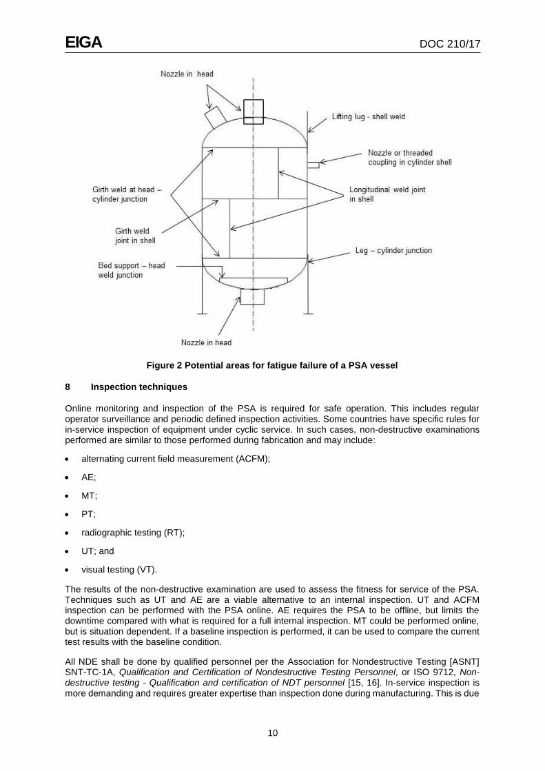
Mechanical fatigue damage can occur at weld locations as shown in Figure 2.
Hydrogen embrittlement
Generally, hydrogen embrittlement is the degradation of material properties due to the presence of a hydrogen environment above a hydrogen partial pressure of 14.5 psi (1 bar). Hydrogen embrittlement manifests itself as reduction in tensile strength and ductility, accelerated fatigue crack growth, and cracking under a sustained load. The susceptibility to hydrogen embrittlement is heavily dependent on the strength of the material and hydrogen partial pressure.
Corrosion
Vessels and piping in a PSA unit can be affected by internal corrosion. The corrosion mechanism can both initiate and compound the fatigue cracking mechanism.
EIGA DOC 210/17
10
Figure 2 Potential areas for fatigue failure of a PSA vessel
8 Inspection techniques
Online monitoring and inspection of the PSA is required for safe operation. This includes regular operator surveillance and periodic defined inspection activities. Some countries have specific rules for in-service inspection of equipment under cyclic service. In such cases, non-destructive examinations performed are similar to those performed during fabrication and may include:
• alternating current field measurement (ACFM);
• AE;
• MT;
• PT;
• radiographic testing (RT);
• UT; and
• visual testing (VT).
The results of the non-destructive examination are used to assess the fitness for service of the PSA. Techniques such as UT and AE are a viable alternative to an internal inspection. UT and ACFM inspection can be performed with the PSA online. AE requires the PSA to be offline, but limits the downtime compared with what is required for a full internal inspection. MT could be performed online, but is situation dependent. If a baseline inspection is performed, it can be used to compare the current test results with the baseline condition.
All NDE shall be done by qualified personnel per the Association for Nondestructive Testing [ASNT] SNT-TC-1A, Qualification and Certification of Nondestructive Testing Personnel, or ISO 9712, Non-destructive testing - Qualification and certification of NDT personnel [15, 16]. In-service inspection is more demanding and requires greater expertise than inspection done during manufacturing. This is due
EIGA DOC 210/17
11
to environmental conditions and uncertainties surrounding the invisible portions of the weld being inspected (i.e., inner surface is not accessible). Inspectors shall be experienced and capable of interpreting results, hypothesizing causes, and recognizing when the inspection procedure may need to change for the as-built weld details.
Based on industry experience, the following should be considered:
• During baseline inspection, characterize longitudinal seam peaking, vessel roundness, and misalignment in order to confirm dimensions used for fitness for service assessment;
• During baseline inspection, characterize and record internal and external weld cap profile for future fitness for service assessment and verify the weld is amenable to be inspected by transverse angle beam UT;
• Utilize a UT qualification block, representative of the PSA weld seams, to qualify inspection procedures and inspectors; and
• Some UT inspection methods use data acquisition and storage to allow evaluation of the inspection after the fact; this data can be useful for future reference.
Online actions
The design life of PSA equipment is determined using the operating pressure range and the number of cycles. The number of cycles is calculated from the cycle time specified by process and the desired design life in years. The PSA inspection plan (IP) is based on the design life. Appropriate controls shall be in place to provide assurance that the equipment is operated within the design conditions. Control of the operating conditions may be accomplished through instrumentation and electronic controls or by administrative control.
Regular review of the operating conditions is useful to determine whether the operating conditions are more or less severe than the design conditions. Historical data that includes the high and low operating pressures and actual cycle time are most useful. Cycle time can be reasonably estimated based on production data and a reasonable correlation between production data and cycle time. For periods of time in which no historical operating or production data is available, the design conditions may be used.
If the PSA operating conditions are changed, the IP shall be assessed. If the new operating conditions are more severe than the original design conditions, the IP shall be adjusted. If the new operating conditions are less severe than the original design conditions, the IP may be adjusted.
During operation, visual and audible surveillance of the PSA system for indications of damage or leakage shall be conducted. Observe the shell for cracks, corrosion, or other signs of damage. For insulated vessels and piping, inspection for potential corrosion under insulation should be performed.
Routine surveillance should be conducted by operations staff with personal gas detectors to detect leaks to atmosphere. Fixed atmospheric gas detection systems (e.g., LEL detectors) may be used to continuously monitor PSA systems.
Where regulatory authorities allow, there are several NDE methods that can be conducted while the PSA is operating. These include surface techniques such as MT, PT, and ACFM and volumetric techniques (e.g., UT) that can look through the thickness of the pressure boundary. Surface inspection techniques are limited to finding surface breaking defects. ACFM has the ability to find such defects without removing the paint coating on the vessel. The technique is primarily used to screen for defects, though it does have some ability to size defects. The ACFM method requires a qualified person who can calibrate and interpret test results.
MT and PT require the paint to be removed from the vessel surface. MT can be performed using a wet or dry powder method. Wet fluorescent magnetic particle testing (WFMT) has the greatest sensitivity to find defects, but requires the use of a black light, which can be difficult in outside conditions. Dry powder MT methods do not require the use of a black light and are more suitable for outside conditions. Dye penetrant testing (PT) can be done in lieu of MT, but has decreased sensitivity compared to MT. The MT and PT methods shall be performed by a qualified person. Both MT and PT will only provide the length of the indication on the inspection surface and have no ability to characterize the depth of the

EIGA DOC 210/17
12
indication or find defects below the inspection surface.
There are various UT methods that are capable of inspecting the entire volume of the pressure boundary including the inside surface of the vessel. UT thickness testing can be used to confirm the thickness of the base metal, the thickness of the weld, and to search for laminations in the base metal. In addition, UT thickness readings can be used to approximate the inner weld surface profile as shown in Figures 3 and 4.
Pulse-echo is an ultrasonic angle beam technique that can be performed manually or conducted automatically by connecting transducers to a robotic crawler.
Figure 3 Weld surface profile example (dimensions in inches)
Figure 4 UT scan coverage plan example
Phased array UT is similar to conventional UT angle beam, except that the probe contains multiple elements to send sound at many angles through the metal. Current technology is capable of sending sound through up to 64 different angles, reducing the sensitivity of the method to the defect’s location and orientation. To accomplish this phased array probes are larger in size than a conventional UT probe. Similar to conventional UT angle beam, phased array inspection should first develop a scan plan to verify coverage and be conducted from both sides of the weld.
Another UT technique is time of flight diffraction (TOFD), which transmits sound from a probe on one side of the weld to a receiver on the other side and measures the time for the diffracted sound wave to pass through the metal. This technique can be done manually or automated using a robotic crawler. TOFD is capable of finding defects regardless of their orientation. Typically, this method has limitations finding defects at the inner and outer surfaces, which is the primary area of interest for PSA inspections. This method may be extended by development of a procedure and testing of the equipment to be able to improve detection at the inner surface. If this additional testing is not done, it should be supplemented with either conventional UT or phased array.
Offline inspection
All of the NDE methods previously described can be performed both on line and offline, while AE is an advanced NDE screening method that can only be executed when the PSA is offline. AE detects crack propagation while the vessel is pressurized to a pressure above the maximum operating pressure. This method can generally locate the crack propagation, but cannot characterize the size of the defect. Follow-up inspection using UT techniques is required to positively locate and characterize the defect. AE shall not be used as a standalone method unless significant sensitivity analysis and FMA is executed.
The adsorbent material contained inside the PSA vessel is stable in its properties (i.e., slow deterioration). There are hazards associated with the removal of adsorbents and it is not possible to
EIGA DOC 210/17
13
simply re-use the multiple layers of adsorbents once they are removed from the vessel. See Section 5. Therefore, the typical industrial practice is to utilize external NDE methods in lieu of internal inspections. The external inspections and monitoring measures described in 8.1 represent state of the art technologies and enable a complete assessment of the mechanical integrity of PSA vessels. Internal inspections are generally executed only if the vessels require a repair as identified by external inspections, or if the adsorbent material is exchanged.
If internal entry is made to replace adsorbents, VT and MT are recommended to be executed on 100% of the longitudinal, circumferential, and nozzle welds. Because of the difficulty of accessing the vessel, internal MT indications are recommended to be repaired. VT inspection should confirm in particular that the weld cap profile is suitable for external UT inspection.
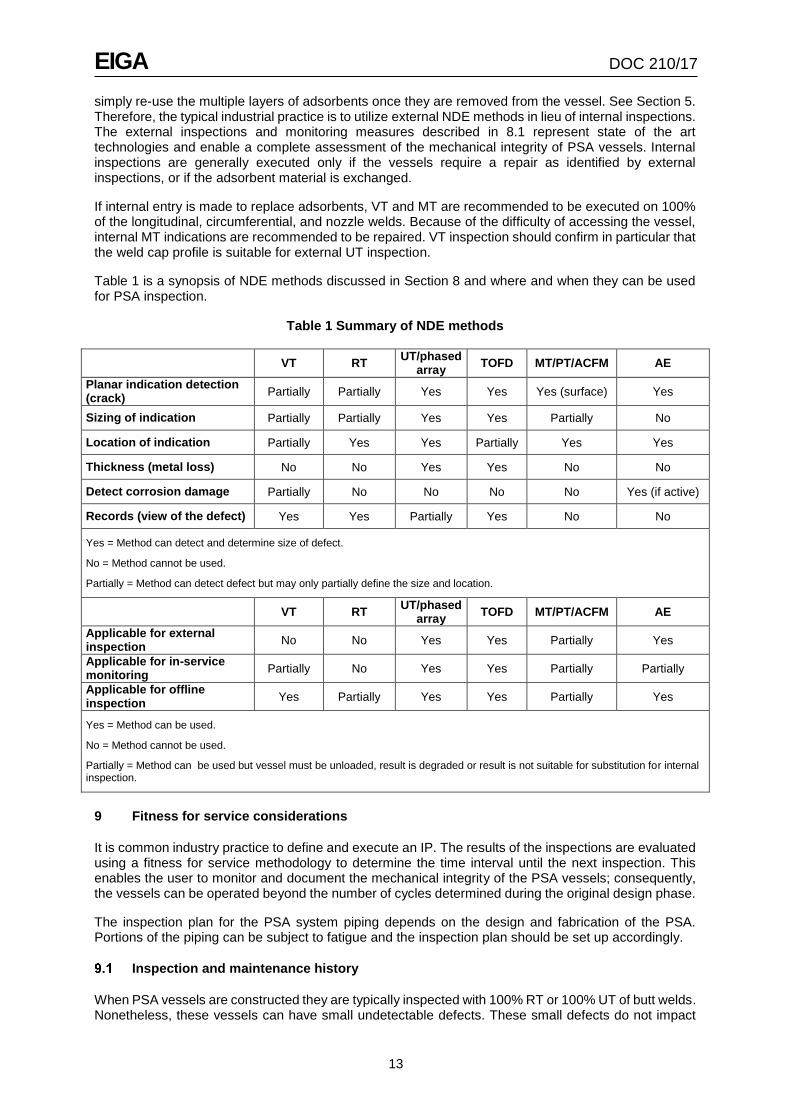
Table 1 is a synopsis of NDE methods discussed in Section 8 and where and when they can be used for PSA inspection.
Table 1 Summary of NDE methods
VT RT UT/phased
array TOFD MT/PT/ACFM AE
Planar indication detection (crack)
Partially Partially Yes Yes Yes (surface) Yes
Sizing of indication Partially Partially Yes Yes Partially No
Location of indication Partially Yes Yes Partially Yes Yes
Thickness (metal loss) No No Yes Yes No No
Detect corrosion damage Partially No No No No Yes (if active)
Records (view of the defect) Yes Yes Partially Yes No No
Yes = Method can detect and determine size of defect.
No = Method cannot be used.
Partially = Method can detect defect but may only partially define the size and location.
VT RT UT/phased
array TOFD MT/PT/ACFM AE
Applicable for external inspection
No No Yes Yes Partially Yes
Applicable for in-service monitoring
Partially No Yes Yes Partially Partially
Applicable for offline inspection
Yes Partially Yes Yes Partially Yes
Yes = Method can be used.
No = Method cannot be used.
Partially = Method can be used but vessel must be unloaded, result is degraded or result is not suitable for substitution for internal inspection.
9 Fitness for service considerations
It is common industry practice to define and execute an IP. The results of the inspections are evaluated using a fitness for service methodology to determine the time interval until the next inspection. This enables the user to monitor and document the mechanical integrity of the PSA vessels; consequently, the vessels can be operated beyond the number of cycles determined during the original design phase.
The inspection plan for the PSA system piping depends on the design and fabrication of the PSA. Portions of the piping can be subject to fatigue and the inspection plan should be set up accordingly.
Inspection and maintenance history
When PSA vessels are constructed they are typically inspected with 100% RT or 100% UT of butt welds.
Nonetheless, these vessels can have small undetectable defects. These small defects do not impact
EIGA DOC 210/17
14
the calculated allowable fatigue life, since the fatigue curves contained in recognized design codes have built in safety factors to account for the inherent detection limits associated with each inspection method (e.g., ASME Code and EN 13445) [1, 2].
Vessel inspection shall be performed to determine the physical condition of the vessel and to determine the type, rate, and causes of damage mechanisms and associated deterioration. This information shall be documented after each inspection.
If defects are detected when an in-service inspection is performed, their location and dimensions shall be documented and quantified. A fitness for service assessment may be performed in accordance with 9.2 or the defect can be repaired per Section 10.
Prior to fatigue evaluation, vessel design, material data, and inspection and maintenance history shall be obtained and the fatigue design criteria from the original code of construction and any special precautions and/or fabrication details shall be evaluated (e.g., ground flush welds, limits on weld peaking, integral reinforcement, etc.).
Determination of fitness for service
Inspection results shall be reviewed and relevant information shall be collected to perform a fitness for service assessment. A fitness for service assessment consists of an inspection, analysis, and final determination of status of the vessel and piping. If the inspection finds no relevant indications, the PSA is fit for service and the existing inspection plan is continued.
A fitness for service assessment processes the results of an inspection. For new and existing vessels there are two possible outcomes of the fitness for service assessment, which are independent of the original design code or standard as shown in Figure 5. This systematic approach ensures that the mechanical integrity of PSA vessels is monitored, evaluated, and documented.

EIGA DOC 210/17
15
Figure 5 Pressure vessels in cyclic service
Explanation of Figure 5
Inspection plans typically focus on the most fatigue critical areas of the vessel first and the remainder of the vessel is examined later in its lifetime. There are three classes of vessels that might be encountered:
• vessels without cyclic service analysis;
EIGA DOC 210/17
16
• vessels designed for cyclic service, or vessels that have had a subsequent cyclic service analysis performed; and
• vessels designed for cyclic service with additional design and fabrication measures.
For a PSA whose fatigue life is not well defined (A), a calculation based on a recognized code shall be performed to define the design required for cyclic service. A fatigue analysis is required to determine the areas of the vessels which are most critical for cyclic service, typically but not limited to: longitudinal butt welds, nozzle connections to the cylindrical shell of the vessel, and weld repairs to base material. These critical areas will be indicated in the fatigue analysis with the lowest allowed number of cyclic changes, while other less critical areas show a much higher number of allowed cycles. Pathways (B) and (C) are followed if sufficient cyclic service analysis has been performed.
Operation may continue as long as the number of accumulated cycles (NA) is less than the inspection target cycles (Ni). Inspection Plan 1 (IP1) is executed after the inspection target cycles (Ni) are reached. The term Ni is used in the cumulative form in order to be directly compared to the actual cycle count Na. For the first inspection, Ni usually is defined at 50 % to 60% of the allowed cycles (NZ) except for Pathway C where it may be equivalent to NZ.
If after execution of IP1 no relevant indications are found, the re-inspection plan (IP2) will be executed after reaching 100% of the allowed cycles (NA=NZ). IP1 covers all critical areas, while IP2 covers all areas (i.e., 100%) relevant for the cyclic design. IP2 is executed when the accumulated cycles during operation (NA) are equal or above the allowed cycles (NZ). If no cracks are detected, the new re-inspection interval (with a new Ni) will be defined. Ni is usually redefined as approximately 30% to 50% of the original allowed cycles (NZ) and a re-inspection shall be executed. This inspection interval can be continued until a relevant indication is detected, at which time an assessment shall be made to determine whether this indication allows further operation. Immediate repair could be one solution while alternatively assessment by execution of a fracture mechanics analysis (FMA) can be applied.
The FMA calculates the size of the detected defects (indications) and the theoretical speed at which these defects would propagate into the vessel with pressure cycles. The interval between two inspections is defined such that a defect at one inspection would not grow beyond the threshold crack size before the next scheduled inspection. The threshold crack size is defined as approximately 50% of the calculated critical crack size that can lead to unstable crack growth and potential rupture of the vessel.
If the FMA results provide a feasible re-inspection interval, then vessel operation can continue. The results with a new calculated inspection interval (new Ni) will then define when the scope of IP1, including the area with the detected defects, will be re-inspected. If a reasonable new re-inspection interval is not feasible, a repair shall be executed or the vessel shall be retired.
See Appendix A for further discussion on Figure 5, and Appendix B for examples of the use of Figure 5.
10 Repair considerations
Any repairs after the vessels have been delivered and placed in service are subject to the control of the local authority having jurisdiction (AHJ). If provisions in recognized repair codes present a direct or implied conflict with jurisdictional regulations, the jurisdictional regulations shall govern.
If repair of welds or cracks is required, the overall repair program and methodology shall be approved by a competent person and duly documented. Design regulations and standards shall be followed.
In principle, a weld repair requires grinding and removal of all defects. Absence of any defects shall be verified preferably by MT or alternatively, PT. The weld repair has to be executed on the basis of the recognized repair procedure of the applicable pressure vessel code.
In addition to the common industry practice of using low hydrogen electrodes and inspection of the entire repair area, the following are PSA specific recommendations:
• before repairing a defect in a welded joint or base metal, investigate the cause of the defect and determine the extent and likelihood of recurrence;

EIGA DOC 210/17
17
• ensure smooth grinding of repair weld and suitable NDE;
• carefully control the weld and heat affected zone (HAZ) hardness; and
• use residual stress management (e.g., post weld heat treatment [PWHT] of the weld, or alternatives).
When conducting a repair, ensure the repair restores the vessel to the original design condition. If the repair cannot restore the vessel to the original design condition, update the fitness for service assessment and corresponding inspection plan accordingly.
11 References
Unless otherwise specified, the latest edition shall apply.
[1] ASME Boiler and Pressure Vessel Code, American Society of Mechanical Engineers, www.asme.org
[2] EN 13445, Unfired Pressure Vessels, www.cen.eu
[3] GB 150, Pressure Vessels, Standardization Administration of China, Room 1602, South Tower, Shangdu SOHO, No 8, Dongdaqiao Road, Chaoyang District, Beijing, 100020 China. www.sac.gov.cn
[4] AD 2000, Pressure Vessel Code, Arbeitsgemeinschaft Druckbehälter (AD), www.fdbr.de
[5] PD 5500, Specification for unfired, fusion welded pressure vessels, www.bsigroup.com
[6] AS1210, Pressure Vessels, Standards Australia, www.standards.org.au
[7] CGA P-11, Metric Practice Guide for the Compressed Gas Industry, www.cganet.com
[8] EN 13480, Metallic industrial piping, www.cen.eu
[9] ASME B31.3, Process Piping, ASME International, www.asme.org
[10] ASME B31.12, Hydrogen Piping and Pipelines, ASME International, www.asme.org
[11] NFPA 56, Standard for Fire and Explosion Prevention During Cleaning and Purging of Flammable Gas Piping Systems, www.nfpa.org
[12] Code of Federal Regulations, Title 29 (Labor) Part 1910, Superintendent of Documents, U.S. Government Printing Office, Washington, DC 20402. www.gpo.gov The EIGA edition will reference “Directive 2003/10/EC of the European Parliament and of the Council of 6 February 2003 on the minimum health and safety requirements regarding the exposure of workers to the risks arising from physical agents (noise) (Seventeenth individual Directive within the meaning of Article 16(1) of Directive 89/391/EEC)”
[13] EIGA Doc 190, Plant Integrity Management, www.eiga.eu
[14] API 571, Damage Mechanisms Affecting Fixed Equipment in the Refining Industry, American Petroleum Institute, www.api.org
[15] ASNT SNT-TC-1A, Qualification and Certification of Nondestructive Testing Personnel, Association for Nondestructive Testing, www.asnt.org
[16] ISO 9712, Non-destructive testing - Qualification and certification of NDT personnel, www.iso.org
Additional references
ASTM A388, Standard Practice for Ultrasonic Examination of Heavy Steel Forgings, www.astm.org
ASTM 578, Standard Specification for Straight-Beam Ultrasonic Examination of Rolled Steel Plates for Special Applications, ASTM International, www.astm.org
EN 10160, Ultrasonic testing of steel flat product of thickness equal or greater than 6 mm (reflection method www.cen.eu

EIGA DOC 210/17
18
EN 10228-3, Non-destructive testing of steel forgings. Ultrasonic testing of ferritic or martensitic steel forgings, www.cen.eu
ISO 5817, Welding - Fusion-welded joints in steel, nickel, titanium and their alloys (beam welding excluded) - Quality levels for imperfections, www.iso.org
ISO 8501-1, Preparation of Steel Substrates Before Application of Paints and Related Products - Visual Assessment of Surface Cleanliness - Part 1: Rust Grades and Preparation Grades of Uncoated Steel Substrates and of Steel Substrates After Overall Removal of Previous Coatings, www.iso.org
Sofronas, A., Fitzgerald, B., and Harding, E., “The Effect of Manufacturing Tolerances on Pressure Vessels in High Cyclic Service”, PVP-Vol. 347, Approximate Methods in the Design and Analysis of Pressure Vessels and Piping Components, Book No. G01059, American Society of Mechanical Engineers, www.asme.org

EIGA DOC 210/17
19
Appendix A—Fitness for service work flow (Normative)
Figure 5—Pressure vessels in cyclic service
EIGA DOC 210/17
20
A. Vessels without cyclic service analysis
Pressure vessel design to recognized codes and standards (e.g., ASME Code, EN 13445,) that does not have a fatigue analysis completed [1, 2]. Additional information may need to be collected to execute the cyclic service calculation, for example: external dimensional inspection of the vessel, observation of weld contours, and complete internal inspection.
B. Vessels designed for cyclic service or vessels that have had a subsequent cyclic service analysis performed
• Pressure vessel design to recognized codes and standards (e.g., ASME Code, EN 13445,) that does have a fatigue analysis completed to calculate the cyclic service period (NZ) [1, 2].
• Cyclic service calculation addresses actual as fabricated conditions.
• Cyclic service calculation considers the effect of hydrogen exposure.
C. Vessels designed for cyclic service with additional design and fabrication measures
• Pressure vessel designed, fabricated, tested, and stamped according to ASME Code, Section VIII, Division 1 or Division 2, or EN 13445 [1, 2].
• Vessel specifications are more stringent than those required by ASME Code, Section VIII, Division 1 or Division 2, or EN 13445 [1, 2].
– 100% NDE of butt welds
– More stringent out of round tolerance (peaking)
– No backing plates allowed
– Full penetration welds on all pressure boundary welds, including nozzles
– All nozzles must have weld neck flanges
• The fatigue design is performed according to ASME Code, Section VIII, Division 2 or EN 13445 with stringent analysis review such as finite element analysis (FEA) modelling [1, 2].
• Cyclic service calculation addresses actual as fabricated conditions.
• Perform fracture mechanics analysis in normal operating condition (e.g., pressure, temperature) to assure that vessel will have thru wall crack tolerance capability of a specified size to preclude unstable fracture. This is also known as leak-before-break (LBB) performance.
1. Calculate cyclic service period (NZ)
Calculate the allowable number of cycles for the specified maximum operating condition, NZ, of the vessel to recognized codes and standards such as ASME Code, Section VIII, Division 2, EN 13445, or analyse the vessel per a FMA approach [1, 2]. To perform these calculations, the stress levels need to be understood which may require conducting a finite element analysis (FEA).
2. Define IP's based on cyclic service analysis in vessel areas (NZ)
The IP shall be developed considering the cyclic service for each area of the vessel. The vessel location that has the lowest calculated cyclic period (NZ) shall govern when the inspection plan should be administered. As part of the inspection plan, an inspection interval (initially interval = N i) should be determined that is at a fraction of the calculated cyclic service period, NZ, targeting the governing areas of the vessel. This focused inspection plan is referred to as IP1 in this publication. A broader inspection plan covering more areas of the vessel is administered later in the life of the vessel and is referred to as IP2 in this publication. If Pathway C is being followed, where additional engineering work has been done, the initial inspection interval (Ni) can equal the cyclic period (Nz).

EIGA DOC 210/17
21
3. Inspection decisions based on NA
Determine if the actual number of cycles (NA) is equal to or exceeds the defined inspection target (Ni):
• NA > Ni;
• NA ≥ NZ; or
• NA is less than the Ni or NA is between the Ni and NZ (all others).
4. Execute IP1
Execute the targeted inspection plan, IP1.
5. Execute IP2
Execute the targeted inspection plan, IP2.
6. Relevant indication detected?
Determine if the inspection plan detects any relevant indications. A relevant indication is an indication that exceeds the acceptance criteria for the selected NDE method as defined in IP1. For example, surface connected linear indications or subsurface planar indications.
7. Determine inspection interval and continue operation
If NA is less than 100% of NZ, continue the existing IP. If NA is greater than 100% of NZ, the IP may need to be revised in order to continue vessel operation. The revised inspection interval should be a fraction of NZ. Add interval to Ni (Ni (old) + Δ Ni = Ni (new)).
8. Assessment of indication allows further operation?
A qualified person shall assess the relevant indications and determine whether further engineering analysis should be pursued to allow continued operation of the vessel. Items to consider are:
• the inspection results may need to be presented to the local authority;
• indication that requires immediate repair; and
• safety and economic analysis determines executing repair is preferred.
9. Execute immediate repair
10. Determine inspection interval based on FMA
Calculate the allowable number of cycles for the actual/anticipated maximum operating condition, NZ, (NA + Δ NZ = NZ(new)) of the vessel by FMA. Determine new interval and add to NA (NA + Δ Ni = Ni [new]).
11. Further operation feasible?
Based on FMA, determine if the resulting inspection interval allows continued operation. Add interval to Ni last (Ni next).
12. Define modified IP
Revise IP1 and/or IP2 to address revised vessel condition.
13. Define and execute repair
Define a repair scope based on the previously performed FMA that allows continued operation.
14. Repair and inspection after repair successful?
Determine if the repair effort met the intent. If necessary, revise the repair scope; if warranted, remove

EIGA DOC 210/17
22
the vessel from service.
15. Determine inspection interval
The nature of the repair may improve the condition of the vessel and increase the remaining allowable cycles (NZ). Alternatively, it may reduce the number of remaining cycles because the repair scope only addressed some of the indications found in the vessel, or the method of repair reduced the vessel’s capabilities. When conducting a repair, ensure the repair restores the vessel to the original design condition. If the repair cannot restore the vessel to the original design condition, update the fitness for service and corresponding inspection plan accordingly.
16. End of life (retire vessel)

EIGA DOC 210/17
23
Appendix B - Examples of fitness for service work flow (Informative)
Example 1Vessel without calculation for cyclic service (pathway A in flow diagram)
A new vessel was acquired by company XYZ, constructed to ASME Code, Section VIII, Division 1 but did not have a cyclic service analysis performed on it [1]. Company XYZ would like to put this vessel in PSA service.
Step 1: Company XYZ performs cyclic service analysis using ASME Code, Section VIII, Division 2 and
determines the cyclic service period (NZ) = 1 000 000 cycles [1]. Step 2: Company XYZ develops an IP identifying the areas of the vessel with the lowest calculated cyclic period, NZ. Company XYZ establishes a focused inspection (IP1) at an interval (Ni) of 500 000 cycles on a longitudinal seam using ultrasonic shear wave (UTSW). Company XYZ establishes a broader inspection (IP2) at 1 000 000 cycles on all pressure boundary welds of the vessel. Step 3: The PSA vessel runs for 510 000 cycles (NA), which exceeds the focused inspection (IP1) target (Ni). Step 4: Company XYZ executes the focused inspection (IP1). Step 6: The inspection company reports no relevant indications were found. Step 7: Company XYZ determines the inspection interval (Δ Ni) is 500 000 cycles and sets the new inspection target at 1 000 000 cycles (Ni). Step 3: The PSA vessel runs to 1 001 000 cycles (NA), which exceeds the broader inspection (IP2) target (NZ). NA > NZ Step 5: Company XYZ executes the broader inspection (IP2). Step 6: The inspection company reports no relevant indications were found. Step 7: Company XYZ chooses to extend the life of the vessel by establishing a new cyclic service period of 250 000 cycles and establishes a new inspection interval of 125 000 cycles. NA + Δ Ni = Ni(new) and NA + Δ NZ = NZ(new) NZ(new) = 1 001 000 + 250 000 = 1 251 000 Ni(new) = 1 001 000 + 125 000 = 1 126 000 Step 3: The PSA vessel runs to 1 126 000 cycles (NA), which exceeds the focused inspection (IP1) target (Ni). NA > Ni Step 4: Company XYZ executes the focused inspection (IP1). Step 6: The inspection company reports no relevant indications were found. Step 7: Company XYZ determines the inspection interval (Δ Ni) is 125 000 cycles and sets the new inspection target at 1 250 000 cycles (Ni). Step 3: The PSA vessel runs to 1 256 000 cycles (NA), which exceeds the broader inspection (IP2) target (NZ). NA > NZ
Company XYZ continues PSA vessel operation and updates/executes inspection plan accordingly.

EIGA DOC 210/17
24
Example 2Vessel with calculation for cyclic service (pathway B in flow diagram)
A new vessel was acquired by Company ABC, constructed to ASME Code, Section VIII, Division 1 that has a cyclic service analysis performed on it per ASME Code, Section VIII, Division 2. The cyclic service period (NZ) = 1 000 000 cycles.
Step 2: Company ABC develops an IP identifying the areas of the vessel with the lowest calculated cyclic period, NZ. Company ABC establishes a focused inspection (IP1) at an interval (Ni) of 500 000 cycles on a longitudinal seam using UTSW. Company ABC establishes a broader inspection (IP2) at 1 000 000 cycles on all pressure boundary welds of the vessel. Step 3: The PSA vessel runs for 510 000 cycles (NA), which exceeds the focused inspection (IP1) target (Ni). Step 4: Company ABC executes the focused inspection (IP1). Step 6: The inspection company reports relevant indications were found. Step 8: A competent person assesses the relevant indications and determines that an FMA is warranted. Step 10: Company ABC performs an FMA on all of the identified indications. The FMA determines a range of cyclic service periods (NZ), with the shortest cyclic service period equal to 100 000 cycles as a consequence of the most significant indication. Step 11: Company ABC determines further operation is not feasible, and decides to execute a repair. Step 13: Company ABC develops and executes a repair plan to address the most significant relevant indication, leaving other indications unrepaired because FMA analysis showed the remaining indications have an acceptable inspection interval. Step 14: Repair was successful. Step 15: Company ABC determines the inspection interval (Δ Ni) is 250 000 cycles based on the remaining indications. The new NZ = 500 000. NA + Δ Ni = Ni(new) and NA + Δ NZ = NZ(new) NZ(new) = 510 000 + 500 000 = 1 010 000 Ni(new) = 510 000 + 250 000 = 760 000 Step 12: Company ABC updates focused inspection plan (IP1) to address the unrepaired indications. Step 3: The PSA vessel runs for 780 000 cycles (NA), which exceeds the focused inspection (IP1) target (Ni). Step 4: Company ABC executes the focused inspection (IP1). Step 6: The inspection company reports relevant indications were found. Step 8: A competent person assesses the relevant indications and determines that immediate repair is required. Step 9: Company ABC develops and executes a repair plan to address the relevant indications. Step 14: Repair was unsuccessful. Step 16: Vessel is taken out of service because it is unrepairable.
EIGA DOC 210/17
25
Example 3Vessel with calculation for cyclic service (pathway C in flow diagram)
A new vessel was designed and procured by Company DEF, constructed to ASME Code, Section VIII, Division 1 and has had a cyclic service analysis performed on it per ASME Code, Section VIII, Division 2 [1]. In addition, the vessel meets the additional design and fabrication requirements specified in this publication. The cyclic service period (Nz) = 1 000 000 cycles and the inspection interval (Ni) = 1 000 000 cycles.
Step 3: The PSA vessel runs for 1 001 000 cycles (NA), which exceeds the broader inspection (IP2) target (NZ).
Step 5: Company DEF executes the broader inspection (IP2).
Step 6: The inspection company reports no relevant indications were found.
Step 7: Company DEF determines the inspection interval (Δ Ni) is 200 000 cycles and sets the new inspection target at 1 201 000 cycles (Ni).
NA + Δ Ni = Ni(new) and NA + Δ NZ = NZ(new) NZ(new) = 1 001 000 + 200 000 = 1 201 000 Ni(new) = 1 001 000 + 200 000 = 1 201 000
Step 3: The PSA vessel runs to 1 205 000 cycles (NA), which exceeds the broader inspection (IP2) target (NZ). NA > NZ
Step 5: Company DEF executes the broader inspection (IP2). Step 6: The inspection company reports relevant indications were found. Step 8: A qualified person assesses the relevant indications and determines that an FMA is warranted.
Step 10: Company DEF performs an FMA on all of the identified indications. The FMA determines a range of cyclic service periods (NZ), with the shortest cyclic service period equal to 300 000 cycles as a consequence of the most significant indication. The calculated inspection interval (Δ Ni) is 150 000 cycles and sets the new inspection target at 1 355 000 cycles (Ni). NA + Δ Ni = Ni(new) and NA + Δ NZ = NZ(new) NZ(new) = 1 205 000 + 300 000 = 1 505 000 Ni(new) = 1 205 000 + 150 000 = 1 355 000
Step 11: Company DEF determines further operation is feasible; no repairs are required.
Step 12: Company DEF updates the focused inspection (IP1) to address unrepaired indications.
Step 3: The PSA vessel runs to 1 387 000 cycles (NA), which exceeds the focused inspection (IP1) target (Ni). NA > Ni
Step 5: Company DEF executes the focused inspection (IP1).
Step 6: The inspection company reports relevant indications were not found.
Step 7: Company DEF determines the inspection interval (Δ Ni) is 150 000 cycles and sets the new inspection target at 1 537 000 cycles (Ni).
NA + Δ Ni = Ni(new) and NA + Δ NZ = NZ(new) NZ(new) = 1 505 000 + 0 = 1 505 000 Ni(new) = 1 387 000 + 150 000 = 1 537 000
NZ limit overrides the Ni limit and therefore the inspection should be done at approximately 1 505 000 cycles. Company DEF continues PSA vessel operation and updates/executes the inspection plan accordingly.