Hydrogen Design 2520of 2520Equipments
37
Hydrogen Plant Design 6 Design of Equipment PACKED BED ABSORBER Absorber system MEA is used as the absorber and its 14.5% in solution . Amount of gas components present in absorber before entering the packed column is given by: Gas composition vol% kmol CO 2 33.86 905.36 CO 1.60 42.69 H 2 63.73 1703.97 CH 4 0.42 11.3 N 2 0.39 10.40 Assumption made in this type of absorber is that only co 2 is absorbed and all other gases act as a inert in 14.5% MEA solution Gas flow rate of inerts (G m ) = 1768.35 kmol/hr Also the mole ration of carbon dioxide and inerts at top and bottom is given by Y b (kmole of CO 2 /kmole of inerts) = 0.51 Y t (kmole of CO 2 /kmole of inerts) =0.014 G m, , Y t L m, X t
-
Upload
erenpaksoy -
Category
Documents
-
view
230 -
download
2
description
hidrojen design
Transcript of Hydrogen Design 2520of 2520Equipments

Hydrogen Plant Design
6 Design of Equipment
PACKED BED ABSORBER Absorber system MEA is used as the absorber and its 14.5% in solution . Amount of gas components present in absorber before entering the packed column is given by: Gas composition vol% kmol CO2 33.86 905.36 CO 1.60 42.69 H2 63.73 1703.97 CH4 0.42 11.3 N2 0.39 10.40 Assumption made in this type of absorber is that only co2 is absorbed and all other gases act as a inert in 14.5% MEA solution Gas flow rate of inerts (Gm) = 1768.35 kmol/hr Also the mole ration of carbon dioxide and inerts at top and bottom is given by Yb (kmole of CO2/kmole of inerts) = 0.51 Yt (kmole of CO2/kmole of inerts) =0.014 Gm,, Yt Lm,
X t

Hydrogen Plant Design
By carbon dioxide balance we get Gm(Yb – Yt) = Lm(Xb – Xt) Assuming a pure MEA solution is used for absorbtion Therefore Xt=0 We get LmXb = 877.10 kmol/hr
Now from graph (Lm/Gm)min = 0.508 also (Lm/Gm)actual = (1.1 to 1.5 times)(Lm/Gm)min now assuming (Lm/Gm)actual = 1.25X(Lm/Gm)min (Lm/Gm)actual = 1.25X0.508 =0.6375 also Gm =1768.35 kmol/h Lm=1768.35X0.6375=1127.32 kmol/hr But the amount obtained is only of MEA , thus amount of solution is given by Lm=1127.32/14.5 X10-2 =7774.64 kmol/hr From above equation we get Xb =0.113

Hydrogen Plant Design
Column diameter calculation: Gb = 44910.82 kg/hr Gb = 12.48 kg/sec Lb= Lm X 24.25 + 877.10 X 44 Lb =227127.42 kg/hr = 63.09 kg/sec Also calculated density of gases and liquids are For liquid ρliq =992.06 kg/m3 µ =0.9 cp(from perry) for gases ρgas=0.626 kg/m3
Let us choose ,Intalox saddles ,ceramic as packing material From table 18-5 ,page 18-23, of perry We get Dp= 38 mm ε =0.80 Specific surface area =195 m2/m3 Fp=170 Now we have L/G x (ρg/ρl)
1/2 = (63.09/12.48)X(0.626/992.06)0.5 = 0.126 Where L =liquid mass rate ,kg/(m2.s) G =Gas mass rate,kg/(s.m2) Also from fig 18- 38, page 18-22 of perry
Hydrogen Plant Design
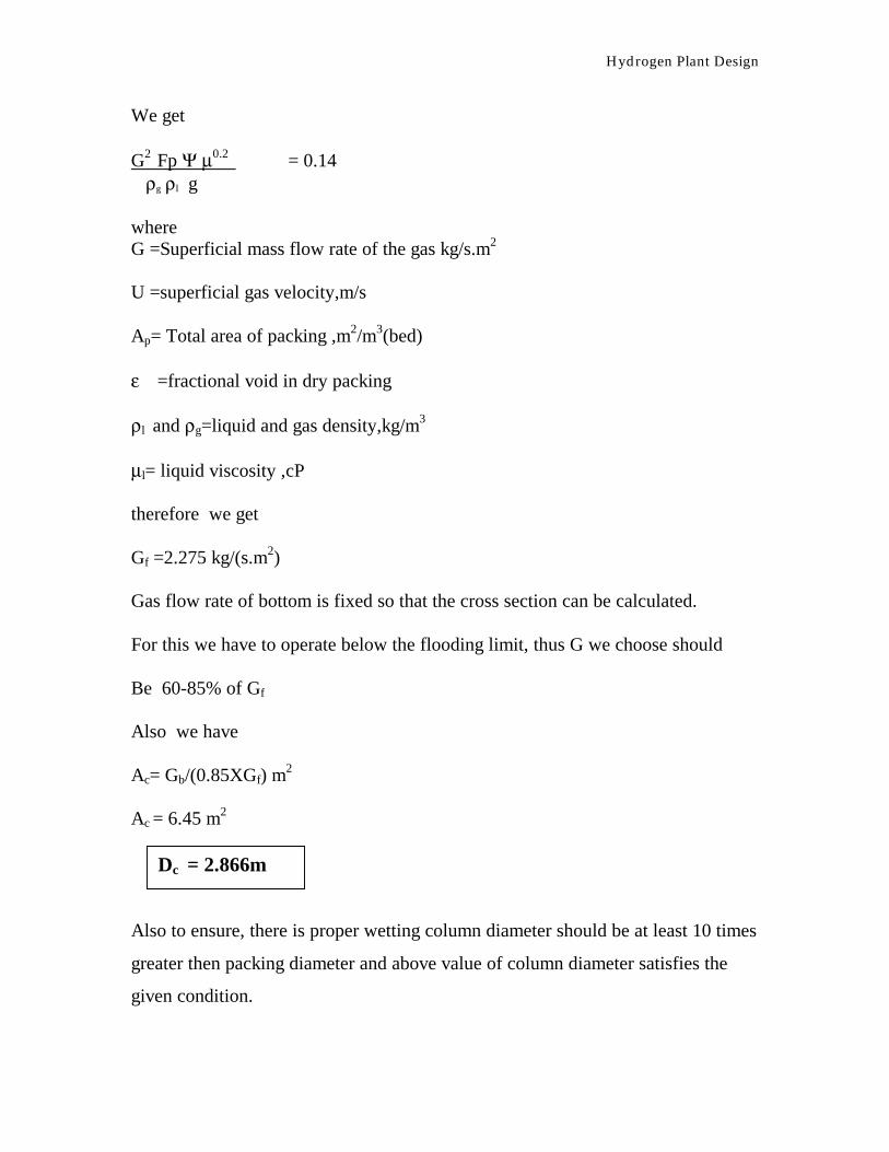
We get G2 Fp Ψ µ0.2 = 0.14 ρg ρl g where G =Superficial mass flow rate of the gas kg/s.m2 U =superficial gas velocity,m/s Ap= Total area of packing ,m2/m3(bed) ε =fractional void in dry packing ρl and ρg=liquid and gas density,kg/m3 µl= liquid viscosity ,cP therefore we get Gf =2.275 kg/(s.m2) Gas flow rate of bottom is fixed so that the cross section can be calculated. For this we have to operate below the flooding limit, thus G we choose should Be 60-85% of Gf Also we have Ac= Gb/(0.85XGf) m
2
Ac = 6.45 m2 Also to ensure, there is proper wetting column diameter should be at least 10 times
greater then packing diameter and above value of column diameter satisfies the
given condition.
Dc = 2.866m
Hydrogen Plant Design
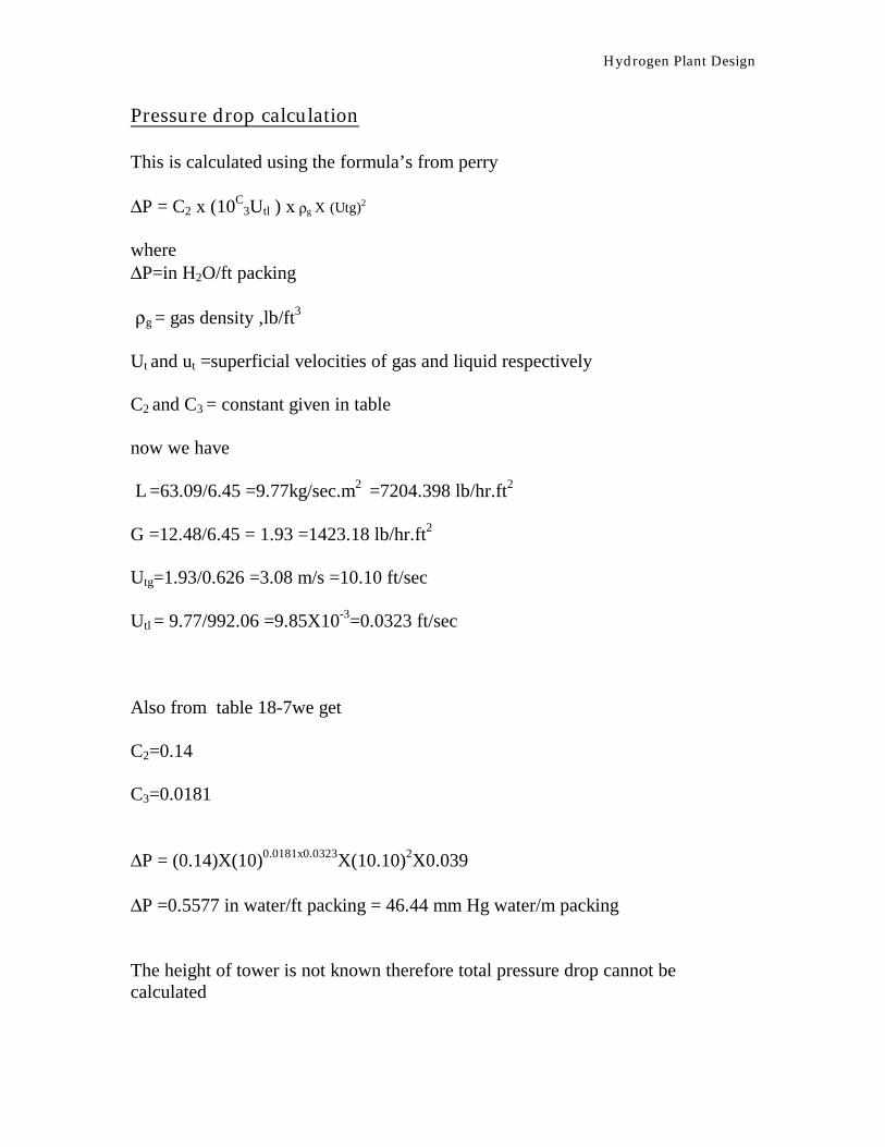
Pressure drop calculation This is calculated using the formula’s from perry ∆P = C2 x (10C
3Utl ) x ρg X (Utg)2
where ∆P=in H2O/ft packing ρg = gas density ,lb/ft3
Ut and ut =superficial velocities of gas and liquid respectively C2 and C3 = constant given in table now we have L =63.09/6.45 =9.77kg/sec.m2 =7204.398 lb/hr.ft2 G =12.48/6.45 = 1.93 =1423.18 lb/hr.ft2 Utg=1.93/0.626 =3.08 m/s =10.10 ft/sec Utl = 9.77/992.06 =9.85X10-3=0.0323 ft/sec Also from table 18-7we get C2=0.14 C3=0.0181 ∆P = (0.14)X(10)0.0181x0.0323X(10.10)2X0.039 ∆P =0.5577 in water/ft packing = 46.44 mm Hg water/m packing The height of tower is not known therefore total pressure drop cannot be calculated

Hydrogen Plant Design
Degree of wetting : We have to calculate the degree of wetting rate Lw=L/Agρla
1 Lw =63.09/6.45x992.06x195 Lw = 1.24 ft3/hr.ft Thus wetting is under the specified limit and proper distribution of liquid is taking place. Tower height calculation Z =HOG.NOG HOG= HG + m.(Gm/Lm).Hl
NOG =∫ (1-Y)cm/(1-Y)(Y-Y*) NOG =1/2(ln(1-Yt)/(1-Yb)) +∫ dy/Y-Y*
Calculation of HG
HG = (0.029*Ψ Dc1.11Z0.33 SCg
0.5)/(L f1 f2 f3)0.5-----------(perry)
ScG = gas-phase Schimidt number (dimensionless number)
= µG/ρgDg
D =column diameter, m f1=(µL/µw)0.16,with µW=1.0 mPa.s
Z = packed height, m f2 = (ρw/ρL)1.25 with ρw=1000 kg/m3
L =liquid rate, kg/s.m2 f3 = (σw/σl)0.8, with σw = 72.8 mN/m
ψ =Correlation parameter
Hydrogen Plant Design
From calculation we get
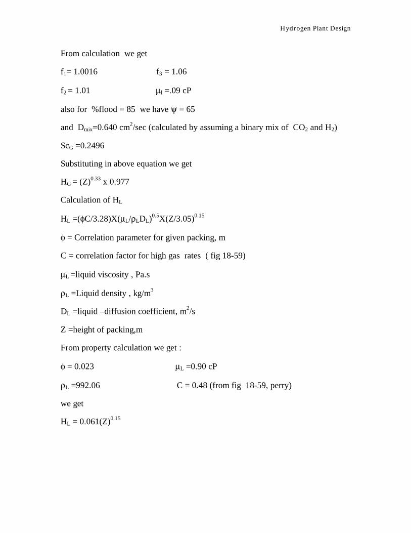
f1= 1.0016 f3 = 1.06
f2 = 1.01 µl =.09 cP
also for %flood = 85 we have ψ = 65
and Dmix=0.640 cm2/sec (calculated by assuming a binary mix of CO2 and H2)
ScG =0.2496
Substituting in above equation we get
HG = (Z)0.33 x 0.977
Calculation of HL
HL =(φC/3.28)X(µL/ρLDL)0.5X(Z/3.05)0.15
φ = Correlation parameter for given packing, m
C = correlation factor for high gas rates ( fig 18-59)
µL =liquid viscosity , Pa.s
ρL =Liquid density , kg/m3
DL =liquid –diffusion coefficient, m2/s
Z =height of packing,m
From property calculation we get :
φ = 0.023 µL =0.90 cP
ρL =992.06 C = 0.48 (from fig 18-59, perry)
we get
HL = 0.061(Z)0.15

Hydrogen Plant Design
Calculation of NOG
We have taken
Lm/Gm = 0.6375
Also we have
NOG = ∫ dy/(Y-Y*) –1/2(ln(1+Yb/1+Yt)
Now from X –Y Graph we get Y*
Which is tabulated here
Y Y* 1/(Y-Y*)
0.51
0.35
0.25
0.23
0.2
0.10
0.014
0.065
0.0425
0.025
0.020
0.0175
0.005
0
2.24
3.25
4.44
4.76
5.48
10.53
71.42
Now from graph we get
NOG =4.75
Also
HOG = HG + m(Gm/Lm)HL
Where
m = slope of linear equlibrium relationship

Hydrogen Plant Design
therefore HOG ={ (Z)0.33(0.977) +(0.05)(Z)0.15} Also we get Z = (4.75){ (Z)0.33(0.977) +(0.05)(Z)0.15} Calculating above equation we get Z =10.4 m
Height of Absorber = 10.4 m
Hydrogen Plant Design
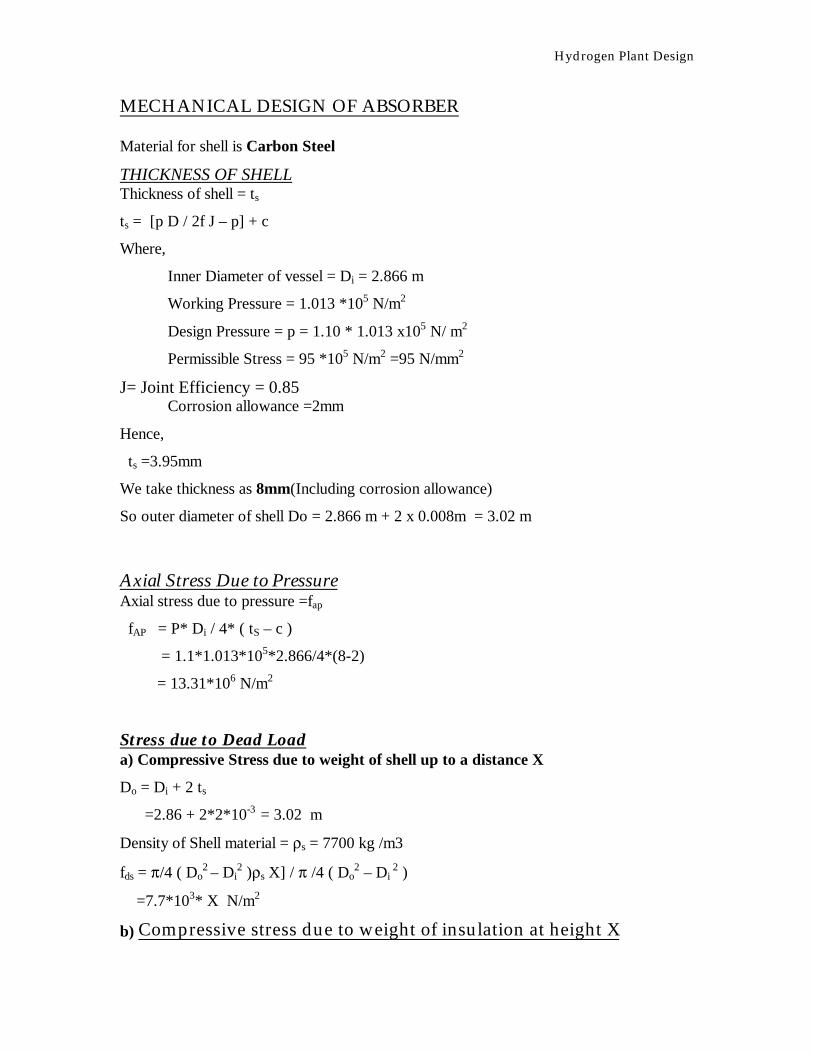
MECHANICAL DESIGN OF ABSORBER Material for shell is Carbon Steel
THICKNESS OF SHELL Thickness of shell = ts
ts = [p D / 2f J – p] + c
Where,
Inner Diameter of vessel = Di = 2.866 m
Working Pressure = 1.013 *105 N/m2
Design Pressure = p = 1.10 * 1.013 x105 N/ m2
Permissible Stress = 95 *105 N/m2 =95 N/mm2
J= Joint Efficiency = 0.85 Corrosion allowance =2mm
Hence,
ts =3.95mm
We take thickness as 8mm(Including corrosion allowance)
So outer diameter of shell Do = 2.866 m + 2 x 0.008m = 3.02 m
Axial Stress Due to Pressure Axial stress due to pressure =fap
fAP = P* Di / 4* ( tS – c )
= 1.1*1.013*105*2.866/4*(8-2)
= 13.31*106 N/m2
Stress due to Dead Load a) Compressive Stress due to weight of shell up to a distance X
Do = Di + 2 ts
=2.86 + 2*2*10-3 = 3.02 m
Density of Shell material = ρs = 7700 kg /m3
fds = π/4 ( Do2 – Di
2 )ρs X] / π /4 ( Do2 – Di
2 )
=7.7*103* X N/m2
b) Compressive stress due to weight of insulation at height X
Hydrogen Plant Design
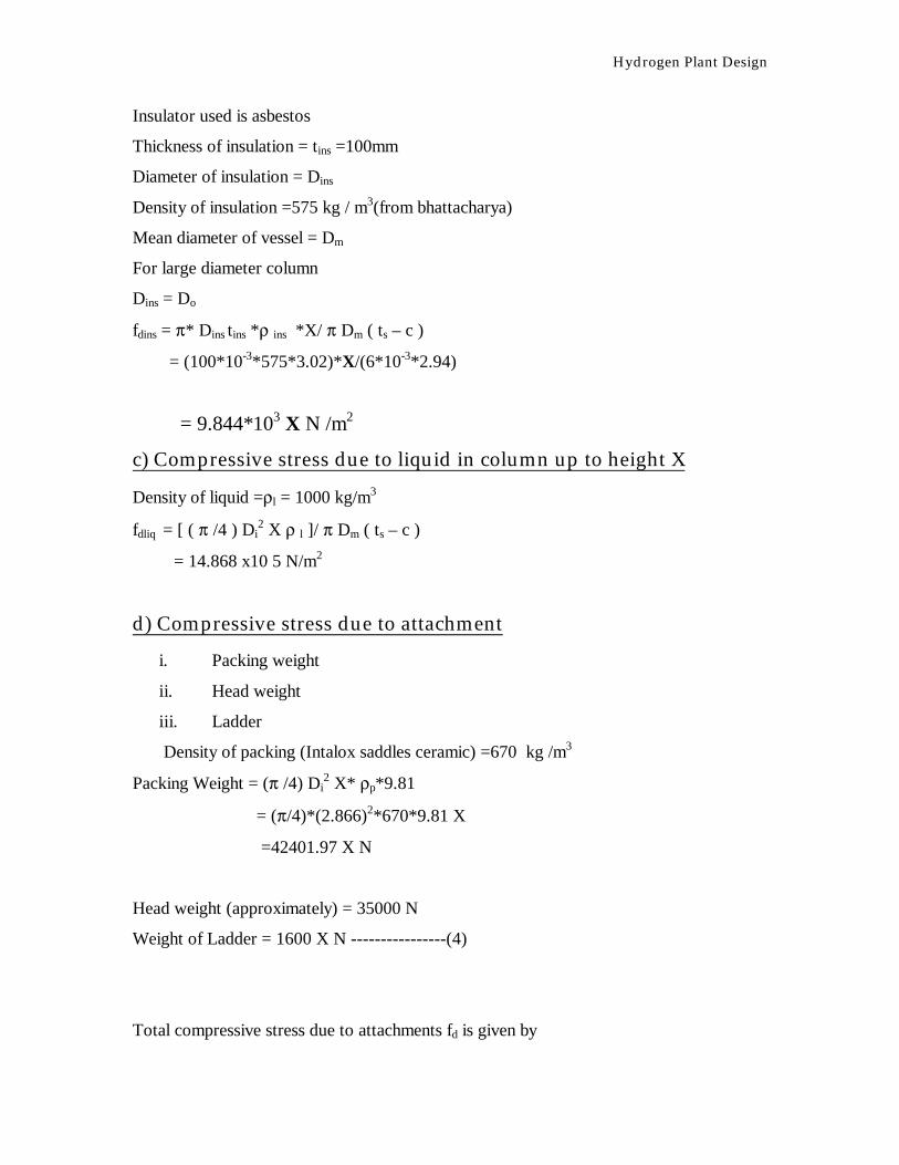
Insulator used is asbestos
Thickness of insulation = tins =100mm
Diameter of insulation = Dins
Density of insulation =575 kg / m3(from bhattacharya)
Mean diameter of vessel = Dm
For large diameter column
Dins = Do
fdins = π* Dins tins *ρ ins *X/ π Dm ( ts – c )
= (100*10-3*575*3.02)*X/(6*10-3*2.94)
= 9.844*103 X N /m2
c) Compressive stress due to liquid in column up to height X
Density of liquid =ρl = 1000 kg/m3
fdliq = [ ( π /4 ) Di2 X ρ l ]/ π Dm ( ts – c )
= 14.868 x10 5 N/m2
d) Compressive stress due to attachment
i. Packing weight
ii. Head weight
iii. Ladder
Density of packing (Intalox saddles ceramic) =670 kg /m3
Packing Weight = (π /4) Di2 X* ρp*9.81
= (π/4)*(2.866)2*670*9.81 X
=42401.97 X N
Head weight (approximately) = 35000 N
Weight of Ladder = 1600 X N ----------------(4)
Total compressive stress due to attachments fd is given by
Hydrogen Plant Design
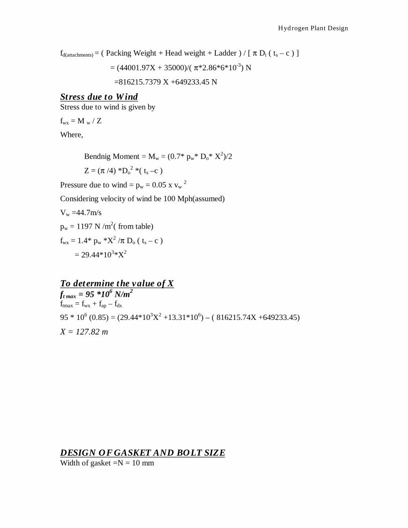
fd(attachments) = ( Packing Weight + Head weight + Ladder ) / [ π Di ( ts – c ) ]
= (44001.97X + 35000)/( π*2.86*6*10-3) N
=816215.7379 X +649233.45 N
Stress due to Wind Stress due to wind is given by
fwx = M w / Z
Where,
Bendnig Moment = Mw = (0.7* pw* Do* X2)/2
Z = (π /4) *Do2 *( ts –c )
Pressure due to wind = pw = 0.05 x vw 2
Considering velocity of wind be 100 Mph(assumed)
Vw =44.7m/s
pw = 1197 N /m2( from table)
fwx = 1.4* pw *X2 /π Do ( ts – c )
= 29.44*103*X2
To determine the value of X ft max = 95 *106 N/m2
ftmax = fwx + fap – fdx
95 * 106 (0.85) = (29.44*103X2 +13.31*106) – ( 816215.74X +649233.45)
X = 127.82 m
DESIGN OF GASKET AND BOLT SIZE Width of gasket =N = 10 mm
Hydrogen Plant Design
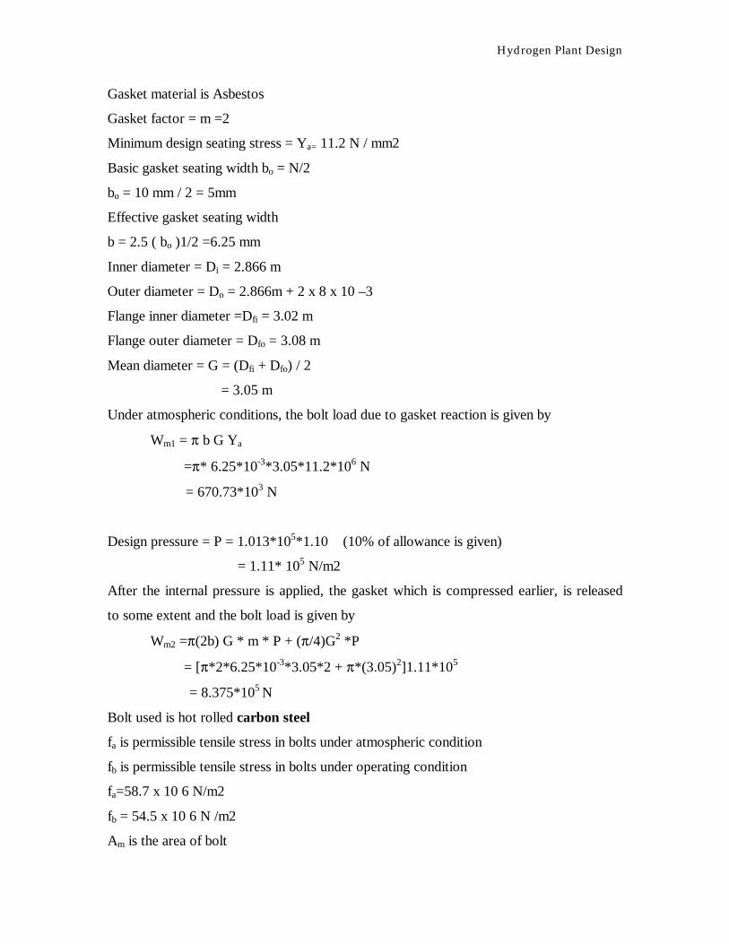
Gasket material is Asbestos
Gasket factor = m =2
Minimum design seating stress = Ya= 11.2 N / mm2
Basic gasket seating width bo = N/2
bo = 10 mm / 2 = 5mm
Effective gasket seating width
b = 2.5 ( bo )1/2 =6.25 mm
Inner diameter = Di = 2.866 m
Outer diameter = Do = 2.866m + 2 x 8 x 10 –3
Flange inner diameter =Dfi = 3.02 m
Flange outer diameter = Dfo = 3.08 m
Mean diameter = G = (Dfi + Dfo) / 2
= 3.05 m
Under atmospheric conditions, the bolt load due to gasket reaction is given by
Wm1 = π b G Ya
=π* 6.25*10-3*3.05*11.2*106 N
= 670.73*103 N
Design pressure = P = 1.013*105*1.10 (10% of allowance is given)
= 1.11* 105 N/m2
After the internal pressure is applied, the gasket which is compressed earlier, is released
to some extent and the bolt load is given by
Wm2 =π(2b) G * m * P + (π/4)G2 *P
= [π*2*6.25*10-3*3.05*2 + π*(3.05)2]1.11*105
= 8.375*105 N
Bolt used is hot rolled carbon steel
fa is permissible tensile stress in bolts under atmospheric condition
fb is permissible tensile stress in bolts under operating condition
fa=58.7 x 10 6 N/m2
fb = 54.5 x 10 6 N /m2
Am is the area of bolt

Hydrogen Plant Design
Am1= Wm1 / fa
Am2 = Wm2 / fb
Am1= 670.73*103/58.7*105
= 0.011 m2
Am2= 0.0154 m2
Number of bolts = mean diameter /bo x 2.5
=244 bolts
To determine the size of bolts, the larger of above two areas should be considered
Diameter of bolts =[(Am2 /Number of bolts) x (4/π)]1/2
=[(0.0154/244)*(4/π)]1/2
=0.90 cm
FLANGE THICKNESS Thickness of flange = tf
tf= [G√(p/K f) ] + c
Where,
K=1/[ 0.3 + ( 1.5 Wm hG)/H x G]
Hydrostatic end force = H = (π /4) G2 P
=(π/4)*(3.05)2*1.11*105 N
=0.78*106 N
hG is radial distance from gasket load reaction to bolt circle,
hG = ( B – G )/ 2
= 3.11-3.05/2
= 0.03m
B = outside diameter of gasket + 2 x diameter of bolt + 12mm
= 3.08 +2*0.90*10-2 +12*10-3
= 3.11 m
Wm = 8.375*105 N
K= 1/(0.3+(1.5*8.375*105*0.03/0.78*106*3.05))
K= 3.166
Hence the thickness of flange = 59.93 mm

Hydrogen Plant Design
HEAD DESIGN: FLANGED & SHALLOW Material stainless steel
Permissible stress = f= 130 N/mm2
Design pressure = p = 1.064 x 10 5 N/m2
Stress identification factor W is given by
W = (¼) [3 + ( Rc/R1)1/2]
Crown Radius = Rc= 2.866m
Knuckle radius = R1 = 0.172 m
So,
Stress identification factor W is 1.77
Thickness of head = th = (p x Rc W)/(2f)
th= 2.07 mm
So , we can take thickness of head as that of thickness of shell
NOZZLE THICKNESS Material Carbon steel
Considering diameter of nozzle = Dn =0.5 m
Thickness of nozzle =tn
Material is Stainless steel ( 0.5 cr 18 Ni 11 Mo 3)
Permissible stress =130 *106 N/m2
J=0.85
tn=P*Dn /(2 f x J –P)
tn = 0.24
No corrosion allowance , since the material is stainless steel.
We can use thickness of 3mm
SUPPORT FOR ABSORBER Material used is structural steel ( IS 800) Skirt support is used.
Inner Diameter of the vessel = Di =2.866 m
Outer Diameter of the vessel = Do =3.02 m
Hydrogen Plant Design
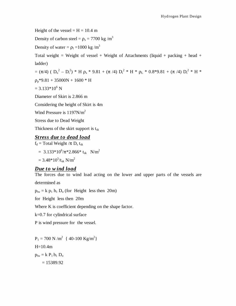
Height of the vessel = H = 10.4 m
Density of carbon steel = ρs = 7700 kg /m3
Density of water = ρl =1000 kg /m3
Total weight = Weight of vessel + Weight of Attachments (liquid + packing + head +
ladder)
= (π/4) ( Do2 – Di
2) * H ρs * 9.81 + (π /4) Di2 * H * ρL * 0.8*9.81 + (π /4) Di
2 * H *
ρp*9.81 + 35000N + 1600 * H
= 3.133*106 N
Diameter of Skirt is 2.866 m
Considering the height of Skirt is 4m
Wind Pressure is 1197N/m2
Stress due to Dead Weight
Thickness of the skirt support is tsk
Stress due to dead load fd = Total Weight /π Ds tsk
= 3.133*106/π*2.866* tsk N/m2
= 3.48*105/tsk N/m2
Due to wind load The forces due to wind load acting on the lower and upper parts of the vessels are
determined as
plw = k p1 h1 Do (for Height less then 20m)
for Height less then 20m
Where K is coefficient depending on the shape factor.
k=0.7 for cylindrical surface
P is wind pressure for the vessel.
P1 = 700 N /m2 { 40-100 Kg/m2}
H=10.4m
plw = k P1 h1 Do
= 15389.92
Hydrogen Plant Design
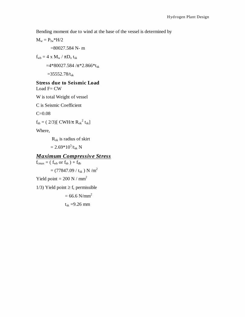
Bending moment due to wind at the base of the vessel is determined by
Mw = Plw*H/2
=80027.584 N- m
fwb = 4 x Mw / πDo tsk
=4*80027.584 /π*2.866*tsk
=35552.78/tsk
Stress due to Seismic Load Load F= CW
W is total Weight of vessel
C is Seismic Coefficient
C=0.08
fsb = ( 2/3)[ CWH/π Rok2 tsk]
Where,
Rok is radius of skirt
= 2.69*105/tsk N
Maximum Compressive Stress fcmax = ( fwb or fsb ) + fdb
= (77847.09 / tsk ) N /m2
Yield point = 200 N / mm2
1/3) Yield point ≥ fc permissible
= 66.6 N/mm2
tsk =9.26 mm
Hydrogen Plant Design
Process Design of Heat exchanger Heat exchanger used is shell and tube. In these exchanger synthesis gas is coming from the cooler of CO
conversion unit. In exchanger the temperature of gas mixture is reduced from 250oC to 25oC . Cold water
is available at 200C.
Shell side:
Feed is the mixture of gas
We have
H2 =0.94665 kg/sec
CO2 = 11.066 kg/sec
CO = 0.33 kg/sec
CH4 = 0.05kg/sec
N2 = 0.081 kg/sec
Therefore from above Mass flow rate of gas is given by
Mg = 12.47 kg/sec
Inlet temperature (T1)= 2500C
Outlet temperature(T2)= 250C
Tube side :
Inlet temperature (t1)= 200C
Outlet temperature(t2)= 400C
Heat balance
Hydrogen Plant Design
Heat supplied by gas is given by Qh = mh Cp* (T2-T1)
Therefore we have
= (0.94665*14.644+ 11.066*0.96 + 1.088*0.33 +0.05*3.01 +1.008)(250-25)
= 5643.84 KW/h
At steady state.
Qh= Qc= mcCP (t2-t1)
5643.84=mc*4.18*(30-20)
mc=67.44 kg/sec
Mass flow rate of gases is 12.7 kg/sec
Mass flow rate of cold water is 67.44 kg/sec
LMTD
LMTD = 54.85oC
We have
R = T1 – T2/t2 – t1
= 225/20 =11.25
S = t2 –t1/T1 – t1 =0.08
FT=LMTD correction factor.
From graph of FT Vs S
Hydrogen Plant Design
FT =0.95
LMTD(corrected )=0.95*54.85=52.110C
Heat transfer area:
We have U range from U = 10 –50 Btu/oFft2hr
Choose overall heat transfer coefficient = 283.9 W/(m2K) =50 Btu/Fft2hr
Q = UA(LMTD)
A=5643.85*103/52.86*0.95*5.678*50
A=388.68m2
Tube selection
Let us choose
¾ in OD ,10 BWG Tubes
OD=3/4 in=19.05 mm
ID=0.62 in=15.75 mm
Length of tube =L=16ft=4.88m
Heat transfer area per tube =0.0598 m2/m length
Heat transfer of one tube = 0.2892
Number of tubes = 388.68/0.2892 = 1344
Let us choose 1-4 pass and U type Heat exchanger
We have
Nearest tube count from tube count table
NT= 1378
¾ in tubes arranged in triangular pitch
shell ID(Df)=1067mm=42in
Corrected heat transfer area=1378*0.2892 m2
=401.41 m2
Corrected over all heat transfer coefficient (U)=274.90 W/(m2K)
Average properties of fluids

Hydrogen Plant Design
a) shell side (gas mixture) at 137.50C
ρ=0.51 kg/m3
µ=0.014*10-3 Ns/m2
Cp=2.008KJ/kg.K
k=0.149 w/m.k
b)tube side (water) at 300C
ρ=995.647 kg/m3
µ=8.5*10-4Ns/m2
Cp=4.18 KJ/kg.K
k=0.621w/m.k
Tube side velocity
Number of passes NP=6
Flow area =(∏*ID2/4)*NT/NP
=(3.14*0.015752/4)*1388/4
Aa =0.068 m2
Vt=mc/ (Aa ρ)
=67.44/(0.068*995.647)
=0.996 m/s
Velocity is within the range.
Shell side velocity Sm=[(Pl-Do)Ls]Ds/ P
l
Pl =pitch=25.4 mm
LS=Ds
=[(25.4-19.05)*1067]*(1067/ 25.4)
=0.285 m2

Hydrogen Plant Design
Vs=mh/(ρ Sm)
=12.70/(0.51*0.285)
=89.12 m/s
Nb+1=L/LS
=4.83/1.067 = 5 baffles
7) Shell side heat transfer coefficient
NNU=jH Nre(NPr)1/3
Where
NNu = Nusselt number
NRe=Reynolds number
NRe= DeGs/µ
Gs = 1886.85
De = 4*((Pt)2*0.86/2 - ∏ d2/4)/(0.5*∏*do)
De = 4.5*10-3 m
NRe = 60635.33
NPr=Prandtl number
=0.74
jh=3*10-3
NNU=10-2*60635.33*(0.74)
=164.53
ho=110.8*0.149/0.01905
=1286.88 w/m2.K
Hydrogen Plant Design
Tube side heat transfer coefficient
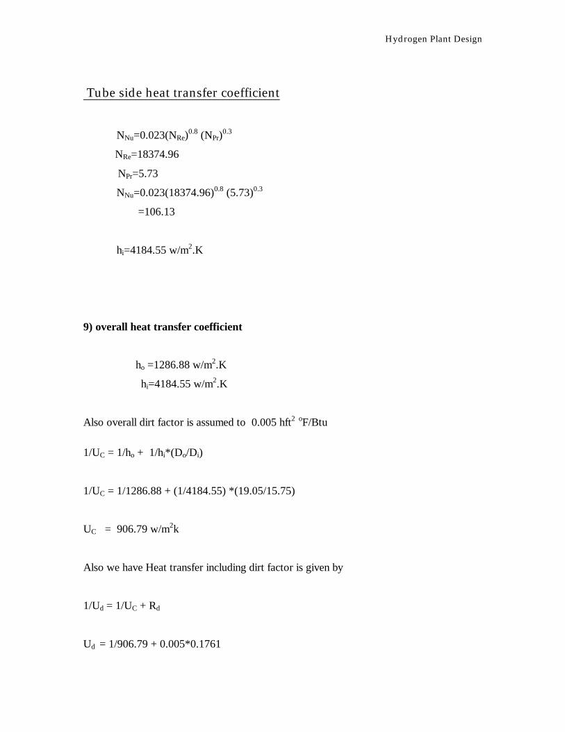
NNu=0.023(NRe)0.8 (NPr)
0.3
NRe=18374.96
NPr=5.73
NNu=0.023(18374.96)0.8 (5.73)0.3
=106.13
hi=4184.55 w/m2.K
9) overall heat transfer coefficient
ho =1286.88 w/m2.K
hi=4184.55 w/m2.K
Also overall dirt factor is assumed to 0.005 hft2 oF/Btu
1/UC = 1/ho + 1/hi*(Do/Di)
1/UC = 1/1286.88 + (1/4184.55) *(19.05/15.75)
UC = 906.79 w/m2k
Also we have Heat transfer including dirt factor is given by
1/Ud = 1/UC + Rd
Ud = 1/906.79 + 0.005*0.1761

Hydrogen Plant Design
Ud = 504.21 w/m2k
Assumed value and design values are almost same.
Pressure drop calculation
a) Tube side pressure drop
Tube side Reynolds number=NRe= 18374.96
friction factor=f=0.079(NRe)-1/4
=0.079(18374.96) -1/4
=0.0068
∆PL=(4fLvt2/2gDi)*ρtg
= (4*0.0068*4.88*(0.996)2/2*9.8*15.75*10-3)*999*9.81
= 4162.0 N/m2 =4.162 KN/m2
∆PE= 2.5(ρt vt2/2)
= 2.5(995.647*(0.996)2/2)
= 1.23*103 N/m2
= 1.23 KN/m2
(∆P)T = Np*(∆PL+∆PE)
= 4*(4.162 +1.23)
= 21.56 KN/m2

Hydrogen Plant Design
b) Shell side pressure drop (Kern’s method)
In the calculation for the heating or cooling gas differs in only minor respects from the
calculation for liquid –liquid system . The relationship between gas film gas film
coefficients and allowable pressure drops are critically dependent upon the operating
pressure of the system where as for incompressible fluids the operating pressure of the
system .
Because of this reason KERN’s method is used for the pressure drop calculation.
as =shell side flow area = (I.D) C1*B/PT
where
C1=clearance =(15/16-3/4)inch =0.187=4.76mm
B=Baffle spacing =Ds
PT =15/16inch =23.8 mm
From above we get
as = 0.2846 m2
also Gs =12.47/0.2846 =43.82 kg/m2.sec
From above shell side reynold’s number is calculated
Which is
Shell side Reynolds number = 60635.33
Also f=1.87*(14085)-0.2
f =0.28
Also
Number of baffles = L/B =4.83/1.067 =5

Hydrogen Plant Design
∆Ps = [4*f*(Nb +1)*Ds*Gs2]/[2*g*Dc*ρg]
∆Ps = [4*0.28*6*1.067*(43.82)2*9.81]/[2*9.81*4.5*10-3*0.51]
∆Ps =20.53 kN/m2
Which is under limit so that we can proceed with our plant design .
Hydrogen Plant Design
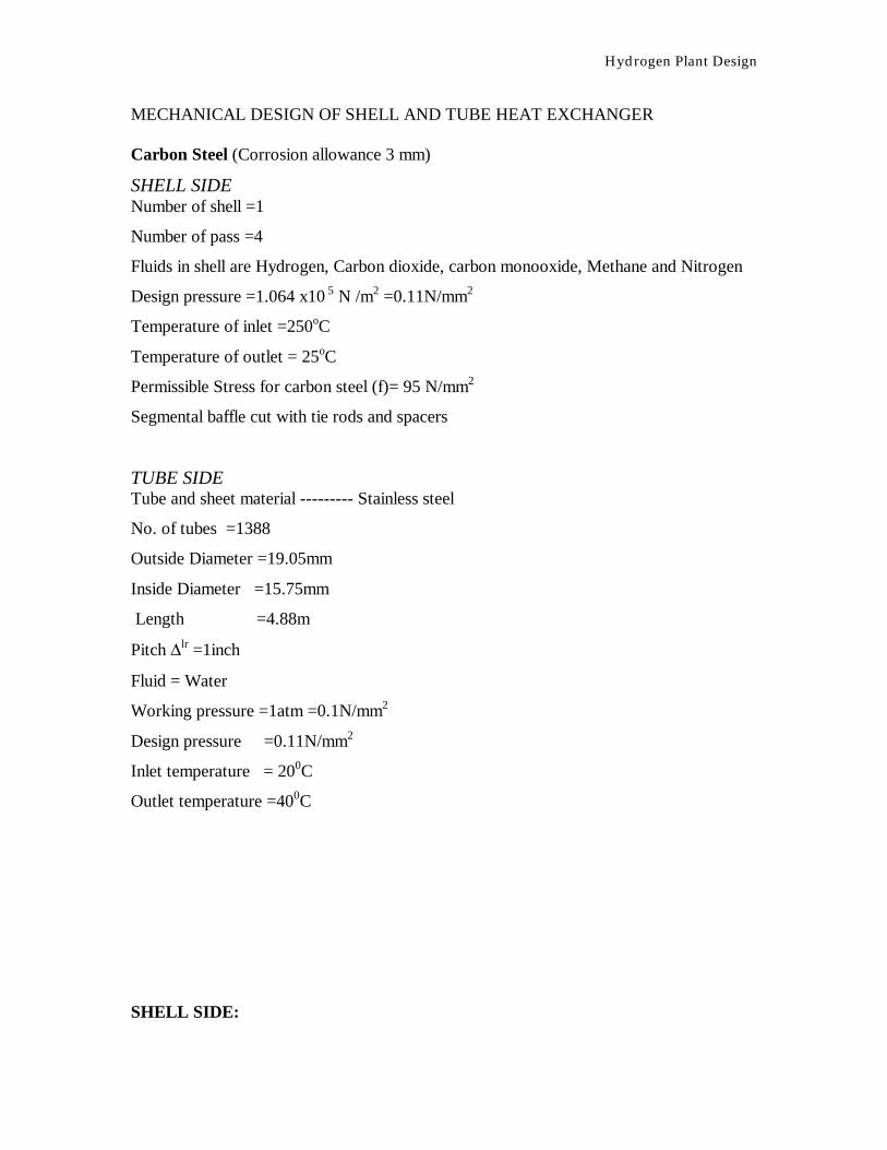
MECHANICAL DESIGN OF SHELL AND TUBE HEAT EXCHANGER Carbon Steel (Corrosion allowance 3 mm)
SHELL SIDE Number of shell =1
Number of pass =4
Fluids in shell are Hydrogen, Carbon dioxide, carbon monooxide, Methane and Nitrogen
Design pressure =1.064 x10 5 N /m2 =0.11N/mm2
Temperature of inlet =250oC
Temperature of outlet = 25oC
Permissible Stress for carbon steel (f)= 95 N/mm2
Segmental baffle cut with tie rods and spacers
TUBE SIDE Tube and sheet material --------- Stainless steel
No. of tubes =1388
Outside Diameter =19.05mm
Inside Diameter =15.75mm
Length =4.88m
Pitch ∆lr =1inch
Fluid = Water
Working pressure =1atm =0.1N/mm2
Design pressure =0.11N/mm2
Inlet temperature = 200C
Outlet temperature =400C
SHELL SIDE:
Hydrogen Plant Design
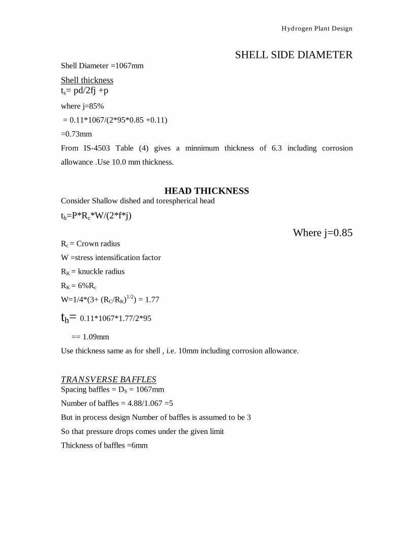
SHELL SIDE DIAMETER Shell Diameter =1067mm
Shell thickness ts= pd/2fj +p
where j=85%
= 0.11*1067/(2*95*0.85 +0.11)
=0.73mm
From IS-4503 Table (4) gives a minnimum thickness of 6.3 including corrosion
allowance .Use 10.0 mm thickness.
HEAD THICKNESS Consider Shallow dished and torespherical head
th=P*Rc*W/(2*f*j)
Where j=0.85 Rc = Crown radius
W =stress intensification factor
RK = knuckle radius
RK = 6%Rc
W=1/4*(3+ (RC/RK)1/2) = 1.77
th= 0.11*1067*1.77/2*95
== 1.09mm
Use thickness same as for shell , i.e. 10mm including corrosion allowance.
TRANSVERSE BAFFLES Spacing baffles = DS = 1067mm
Number of baffles = 4.88/1.067 =5
But in process design Number of baffles is assumed to be 3
So that pressure drops comes under the given limit
Thickness of baffles =6mm
Hydrogen Plant Design
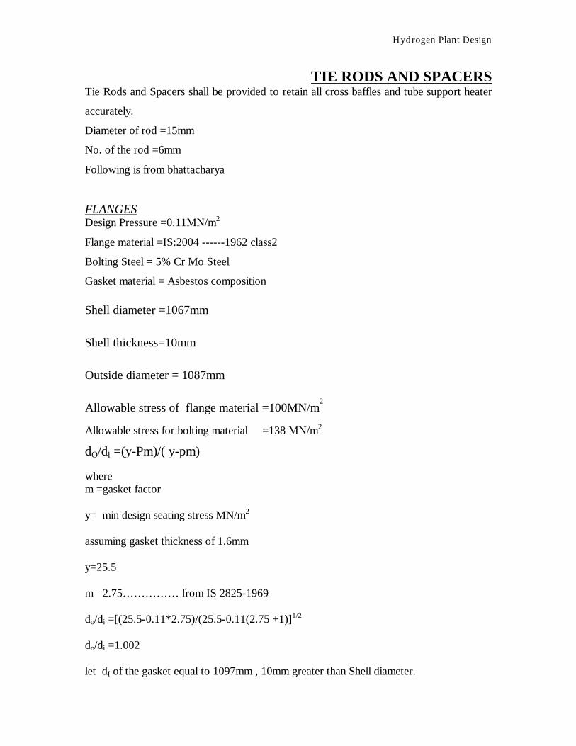
TIE RODS AND SPACERS Tie Rods and Spacers shall be provided to retain all cross baffles and tube support heater
accurately.
Diameter of rod =15mm
No. of the rod =6mm
Following is from bhattacharya
FLANGES Design Pressure =0.11MN/m2
Flange material =IS:2004 ------1962 class2
Bolting Steel = 5% Cr Mo Steel
Gasket material = Asbestos composition
Shell diameter =1067mm
Shell thickness=10mm
Outside diameter = 1087mm
Allowable stress of flange material =100MN/m2
Allowable stress for bolting material =138 MN/m2
dO/di =(y-Pm)/( y-pm) where m =gasket factor y= min design seating stress MN/m2 assuming gasket thickness of 1.6mm y=25.5 m= 2.75…………… from IS 2825-1969 do/di =[(25.5-0.11*2.75)/(25.5-0.11(2.75 +1)]1/2 do/di =1.002 let dI of the gasket equal to 1097mm , 10mm greater than Shell diameter.
Hydrogen Plant Design
Therefore do =1.002*di =1.002*1097 =1099mm Minimum gasket width =do –di /2 = (1099.1-1097)*10-3/2 =0.001m =1mm Taking Gasket width = 0.012m
Diameter of location of gasket load reaction is
G = di +N
= 1.097 +0.010
=1.107 m
Estimation of bolt loads
Load due to design pressure
H= ∏*G2*P/4
=∏ (1.107)2*0.11/4
=0.106 MN
Load to keep joint tight under operation HP=∏*G*(2*b)*m*p
= ∏*(1.107)2*2*5*10-3*2.75*0.11
=0.012 MN
Total operating load :
Wd = H + HP
Hydrogen Plant Design
=0.106 + 0.012
=0.118 MN
load to seat gasket under bolting up condition
Wg =∏*G*b*y
=∏*1.107*0.005*25.5
= 0.44 MN
Also Wg > Wd
Therefore
Controlling load =0.44MN
Minimum bolting area =Am = Wg/Sg
= 0.44/138
=3.19*10-3 m2
Sg =138 from bhattacharya pg no.10
Calculation for optimum bolt size
Let us choose Bolt as M 18X12
Min no. Of bolts = 44
Also
R= 0.027m
We have
G1= B + 2(g1+R)
G1= 1.087 + 2[g1 +R]
g1 =go/0.707 =1.415go for weld leg
G1 =1.087 +2 (1.415*10*10-3 +0.027)
G1 = 1.424
Using 75 mm bolt spacing
C1 = 44*0.075/∏ =1.05m
From the above calculation the minimum bolt circle is 1.424 m when M18 Bolt
44 bolts of 18 mm diameter on 1.424 m bolt circle are specified.
Hydrogen Plant Design
Bolt circle diameter =1.42 m
A = C +Bolt diameter +0.02
= 1.42 +0.018 + 0.02
= 1.458m = 1.46m
Check of gasket width
= Ab*Sg/∏*G*N
= 44*138*1.54*10-3/∏*1.107*0.01
= 26.88
also 26.88<2*y
Flange moment computation W0 = W1 + W2+ W3
W1 = ∏ *B2*P/4
Hydrostatic end force on area inside of flange .
W1 = ∏*(1.087)2*0.11/4
= 0.102 MN
W2 =H- W1
= 0.106 – 0.102 =0.004 MN
WS = Wo – H =HP=gasket load
= 0.012MN
Mo = W1a1 + W2a2 + W3a3
Where Mo = Total Flange moment
a1 = C – B/2 =1.42 –1.0187/2 =0.17
a3 = C1 –C1/2 = 1.424 –1.107/2 =0.1585
a2 = a1 + a3/2 = 0.164m
Mo = 0.102 0.17 + 0.004*0.164 +0.012*0.164
=0.020 MN-m
Hydrogen Plant Design
For bolting up condition
Mg = Wa3
W = Am + Ab/2* Sg
Ab = 44*1.54*10-4 m2
Sg = 138 MN/m2
Am = 3.19*10-3 m2
Am +Ab/2 =4.983*10-3 m2
W = 0.687
Mg = 0.108
Mg > Mo.
Hence moment under operating condition
Mg is controlling
Therefore Mg = M
Calculation of flange thickness t2 = M*Cf*Y/B*ST = M*Cf*Y/B*Sfo
where
k= A/B =1.46/1.087 =1.34
Assuming Cf = 1
Y= 6 from graph
t2 = 0.108*1*6/1.087*100
t = 0.0792 m
Actual bolt spacing
BS = ∏*C/n = ∏*1.42/44 = 0.101
Bolt correction factor Cf =(BS/2*d + t)1/2
Cf = [(0.101)/(2*0.018 +0.101)]1/2
Hydrogen Plant Design
Cf = (0.737)1/2 = 0.858
Actual Bolt thickness = (C)1/2 *t
= 0.93* 0.0792
= 0.0796 = 73.66 mm = 75mm
Tube Sheet Thickness tts = f*G*(0.25*P/f)1/2
tts = 1*1.107* (0.25*0.11/95)1/2
= 0.0188m
tts = 18.83 +3 = 22 mm (Includes corrosion allowance )
Channel and Channel cover Th = GC*(K*P/f)1/2
= 1.107*(0.3*0.11/95)1/2
= 0.0206 m = 22mm (includes corrosion allowance)
Saddle Support Material : low carbon steel
Vessel diameter = 1087mm
Length of shell = 4.88 m
Hydrogen Plant Design
Knuckle Radius = 6*1087/100 = 65.22mm
Total depth of Head = (Do*Ro/2)1/2
=(1087*65.22/2)
= 188.27 mm
Ri= 0.838 m
ri =0.1 x0.838
Inside depth of head can be calculated as
hi = Ri – [ { Ri –( Di / 2 ) }{( Ri + ( Di / 2 ) + 2 ri }]1/2
= 0.136m
Effective Length = L = 4.88 m + 2 x (0.136)
= 5.154 m
NOZZLE THICKNESS Material used is carbon steel
Considering diameter of nozzle to be 0.5m
Permissible stress = f = 95 x 10 6 N/ m2
Corrosion allowance = 3mm
tn = p Dn/( 2f J –p )]+c
=3.26 mm

Hydrogen Plant Design

Hydrogen Plant Design