Report No. BDK84 977-14 Final Report Hydroplaning on Multi Lane ...

1 "----=I
c- ~ I ..
HYDRODYNAMICS OF AIRCRAFT TIRE HYDROPLANING
NATIONAL AERONAUTICS AND SPACE ADMINISTRAT1,ON W A S H I N G T O N , 0. C. AUGUST 1968
-A
https://ntrs.nasa.gov/search.jsp?R=19680022121 2018-06-02T19:17:46+00:00Z

NASA CR- 112 5 TECH LIBRARY KAFB, NM
HYDRODYNAMICS OF AIRCRAFT TIRE HYDROPLANING
By S. Tsakonas, C. J. Henry, and W. R. Jacobs
Distribution of this report is provided in the interest of information exchange. Responsibility for the contents resides in the author or organization that prepared it.
Issued by Originator as Report No. 1238
Prepared under Contract No. NSR, 31-003-016 by STEVENS INSTITUTE O F TECHNOLOGY
Hoboken, N.J.
for
NATIONAL AERONAUTICS AND SPACE ADMINISTRATION ~ ~ ~ ." .. .~
For sale by the Clearinghouse for Federal Scientific and Technical Information Springfield, Virginia 22151 - CFSTI price $3.00


ABSTRACT
An approximate theory has been developed f o r a study of the hydro-
p l a n i n g t i r e by consider ing i t as a p lan ing sur face of smal l aspec t ra t io
in ex t remely sha l low water . The r e s u l t s o f t h i s app rox ima t ion exh ib i t
hydrodynamic behavior s imi lar to that o f hydroplan ing pneumat ic t i res and
thus ind icate that the t i re hydroplan ing phenomenon can be described from
the standpoint of inviscid hydrodynamics. The ana lys i s f u rn i shes f am i l i es
o f curves which can be cons idered to represent , qua l i ta t i ve ly , the s ta r t
o f hydrop lan ing and thus g ive qual i ta t ive gu idance for avo id ing the un-
des i rab le hydrop lan ing cond i t ion .
iii

"

TABLE OF CONTENTS
ABSTRACT . . . . . . . . . . . . . . . . . . . . . . . . . . . . . . i i i
NOMENCLATURE . . . . . . . . . . . . . . . . . . . . . . . . . . . v i i
INTRODUCTION . . . . . . . . . . . . . . . . . . . . . . . . . . . 1
THEORY . . . . . . . . . . . . . . . . . . . . . . . . . . . . . 3
SIMPLIFIED MATHEMATICAL MODEL . . . . . . . . . . . . . . . . . . 8
a) Ground Pressu re D is t r i bu t i on . . . . . . . . . . . . . . 8
c) Evaluat ion o f the Ground-Induced Velocity . . . . . . . . 12
d) Spanwise L i f t D i s t r i b u t i o n . . . . . . . . . . . . . . . 14 e) Total L i f t on the Hydroplaning Tire . . . . . . . . . . . 17
b) Low Aspect Ratio Approximation . . . . . . . . . . . . . . 9
NUMERICAL CALCULATIONS AND DISCUSSION OF RESULTS . . . . . . . . . 23
a ) E f fec ts o f Va r ious Parameters . . . . . . . . . . . . . 23
b) Incept ion o f Hydroplan ing . . . . . . . . . . . . . . 26
CONCLUSIONS . . . . . . . . . . . . . . . . . . . . . . . . . . . 30
ACKNOWLEDGEMENT . . . . . . . . . . . . . . . . . . . . . . . . . 32
REFERENCES . . . . . . . . . . . . . . . . . . . . . . . . . . . 33
FIGURES (1-10)
APPENDIX A APPEND I X B
V


NOMENCLATURE
A = - d b
b
bl
b2
cL
d
L
LG
LT
L '
R
n
a s p e c t r a t i o o f p l a n i n g s u r f a c e
h a l f - l e n g t h o f w e t t e d s u r f a c e o f p l a t e
l ong i tud ina l d imens ion o f f oo tp r in t f r om wheel ax le t o t r a i 1 i ng edge
l o n g i t u d i n a l d i m e n s i o n o f f o o t p r i n t from wheel ax le to lead ing edge
c o e f f i c i e n t o f t o t a l l i f t de f ined i n E q . (37)
c l e a r a n c e o f t r a i l i n g edge of t i r e we t ted su r face from ground
func t i ons de f i ned i n E q . (38)
depth o f water on runway o r ground
kerne l func t ion represent ing induced ve loc i ty on element j due to un i t amp l i t ude l oad on element i
t o t a l 1 i f t on hydrop lan ing t i re
load i ng on ground
load ing on t i r e
cumu la t i ve l oad ing d i s t r i bu t i on
h a l f - w i d t h o f f o o t p r i n t and o f w e t t e d s u r f a c e o f t i r e
index o f summation
t i r e i n f l a t i o n p r e s s u r e
1 i f t i n g s u r f a c e
f o r w a r d v e l o c i t y o f v e h i c l e
u n i t s t e p f u n c t i o n
downwash v e l o c i t y d i s t r i b u t i o n normal t o ground
downwash v e l o c i t y d i s t r i b u t i o n n o m a 1 t o t i r e
vi i

coord ina tes o f con t ro l po in t on g round
coo rd ina tes o f con t ro l po in t on t i r e we t ted su r face
cho rdw ise va r iab le o f i n teg ra t i on
camber o f t i re surface
angle of a t t a c k o f p l a n i n g s u r f a c e
angular chordwise locat ion
va r ious i n teg ra l s
de f i ned i n (29) and (30)
coord inates o f loading po int on ground
coo rd ina tes o f l oad ing po in t on t i r e s u r f a c e
mass d e n s i t y o f f l u i d
angular chordwise locat ion
f u n c t i o n (see Eqs. (15) and (16))
de f i ned i n (31)
viii

INTRODUCTION
Pneumatic t i r e s r o l l i n g on a wet runway may reach a speed where the
t i r e becomes completely detached from the ground and sk ids a long on a
t h i n f i l m o f wa te r . A t t h a t s t a g e , d i r e c t i o n a l s t a b i l i t y and c o n t r o l ,
as w e l l as brak ing t ract ion, are complete ly lost . When t i r e and surface
a re no l o n g e r i n c o n t a c t , t h e t i r e i s s a i d t o be hydroplaning. I t no
l onger ro l Is but s l ides wi thout cont ro l across the sur face.
A s e r i e s o f t h e o r e t i c a l s t u d i e s has been made, based on one o f the
fundamental assumptions, e i t he r t ha t t he hyd rop lan ing phenomenon could be
reasonably expla ined in terms o f f lu id densi ty a lone (hydrodynamic pressure)
o r t h a t i t i s b a s i c a l l y one o f l ~ b r i c a t i o n . ~ A t the same time experimental
s tud ies 495'6 have been conducted i n an e f fo r t t o revea l t he phys i ca l mecha-
n i s m o f t h e h y d r o p l a n i n g t i r e as w e l l as the important parameters affect-
ing the phenomenon.
1,2
Admi t ted ly the t i re -hydrop lan ing phenomenon is qu i te compl ica ted .
Perhaps a t one stage the hydrodynamic aspects o f the phenomenon are
dominated by v i scous e f fec ts (hence l u b r i c a t i o n ) , a t a n o t h e r by i n e r t i a
e f f e c t s and a t a l a te r s tage by thermodynamic e f fec ts ( reve rs ion o f t he
rubber and f o r m a t i o n o f steam pocket) . A t each and every stage, of course,
t h e e l a s t i c p r o p e r t i e s o f t i r e s and t h e i r t e x t u r e and geometry, as w e l l
as the r e l a t i v e roughness o f the wet pavement, enter into the problem.
For those cases o f hydrop lan ing where v e l o c i t y i s
t h e w a t e r i s r e l a t i v e l y deep, i t seems ra the r reasonab
t h e v i s c o s i t y e f f e c t s become i n s i g n i f i c a n t ' f o r such h
q u i t e h i g h and
l e t o assume t h a t
igh Reynolds numbers
as e x i s t a t t h a t s t a g e .
The present study has been based on the p remise tha t the f lu id iner t ia
e f f e c t i s the predominant property. The three-dimensional character o f
the phenomenon has been preserved and the e f fec ts on t i r e hyd rop lan ing
will be obtained due t o a s p e c t r a t i o and shape o f the p lan ing sur face and
1

t o d e p t h o f water , together w i th veh ic le speed. The genera l formulat ion
o f the hydrodynamic aspect o f the non-viscous hydroplaning problem leads.
t o a p a i r o f s u r f a c e i n t e g r a l e q u a t i o n s w i t h unknown l o a d i n g d i s t r i b u t i o n
on the t i r e and on the ground. However, due to t he 1 i m i t a t i o n s o f t h e
c o n t r a c t f o r t h i s i n i t i a l s t u d y an approximate solut ion will be obtained
based on the fo l lowing assumpt ions: a) the t i re is regarded as a low-
a s p e c t r a t i o 1 i f t i n g s u r f a c e , b ) the p ressure d is t r ibu t ion on the pavement
i s approximated by a s tep funct ion o f magni tude g iven by experimental
measurements. The r e s u l t s o f t h i s i n i t i a l i n v e s t i g a t i o n i n d i c a t e t h a t t h e
approximate so lu t ion cor rec t ly p red ic ts the t rend bu t no t the magn i tude
o f the hydrodynamic 1 i f t and conf i rms qual i ta t ive ly the impor tant char-
a c t e r i s t i c s observed in t he t i r e -hyd rop lan ing phenomenon. For fu ture
s tud ies i t is recommended t o improve the mathematical model so that the
three-dimensional non-viscous contr ibut ion may be def ined as accu ra te l y
as poss ib le and t h e n t h e e l a s t i c i t y o f t h e t i r e may be incorporated.
2

THEORY
A t the stage o f complete detachment o f the hydroplan ing t i re f rom
the wet pavement, t he con tac t a rea o f t he t i r e i s assumed t o have i n f i n i t e
rad ius o f curvature as shown in F igu re 1 and a t t ha t s tage t he t o ta l we igh t
o f the vehic le will be sustained by the hydrodynamic pressure d istr ibut ion
developed i n t h e f i l m o f w a t e r between the t i r e and the ground. This
s i t u a t i o n i s s i m u l a t e d by a mathematical model presented in F igure 2 , where
t h e a r e a o f t i r e i n c o n t a c t w i t h t h e f l u i d will be considered as a l i f t i n g
surface o f f i n i t e a s p e c t r a t i o p l a n i n g a t the f ree sur face o f ext remely
sha l low water a t h igh Froude number, s ince the vehic le speed is considered
very h igh .
The r ight -handed Car tes ian coord inate system is se lected wi th pos i t ive
x - a x i s i n t h e d i r e c t i o n o f f l u i d m o t i o n ( o p p o s i t e t h a t o f v e h i c l e ) and
p o s i t i v e z - a x i s i n t h e downward d i r e c t i o n . The p resen t s tudy u t i l i zes
the 1 inear ized 1 i f t i n g s u r f a c e t h e o r y w h i c h i s based on a smal l per tu r -
bat ion approx imat ion together wi th the assumpt ion o f t h i n s u r f a c e s i n
un i fo rm f low o f an i ncompress ib le i nv i sc id f l u id .
The pressure f ie ld genera ted by a 1 i f t i n g s u r f a c e S has been shown
t o be g iven by d is t r ibu ted doub le ts w i th ax is para1 le1 to the loca l normal
and s t rength p ropor t iona l to the p ressure jump across the surface S. I f
these unknown loadings on the t i r e and ground are designatd by LT(cTyTT)
and L ( 5 y l l ) respec t i ve l y , t hen t he k inemat i c cond i t i ons wh ich ex i s t a t
both 1 i f t i n g s u r f a c e s ( t i r e p l a n e and ground) will be expressed mathe-
m a t i c a l l y on the bas is o f 1 inear approx imat ion ( i .e . , smal l per turbat ion
theory) as f o l lows:
G G G
-m
3

where (xT, yTY 0)
and ( T T y y,, 0) = coo rd ina tes o f con t ro l and load ing po in t , respec t ive ly , loca ted on the t i re sur face
(xG,yG,h) and (qGyTG7h) coord ina tes o f con t ro l and load ing po in t , respect ively, located on the ground plate
‘T( and ‘G( the known downwash v e l o c i t y d i s t r i b u t i o n normal t o t h e t i r e and ground p l a t e , r e s p e c t i v e l y
kernel function which represents the induced v e l o c i t y on an element j due t o a un i t ampl i tude load on element i. Subscr ipts i and j designate t i r e o r ground p l a t e .
For the case o f r i g i d p l a t e s the known downwash d i s t r i b u t i o n will be
given by
and
where the f i r s t expresses the fact that the f low remains always tangent
t o the t i r e su r face wh ich has camber given by z(x,y) , and the second
imposes the same requ irernent a t the ground which has been assumed t o be
f l a t .
4

The two equat ions ( 1 ) and (2) c o n s t i t u t e a p a i r o f s u r f a c e i n t e g r a l
equat ions wi th the,unknown loading funct ions LT(cT,llT) and LG(SG,llG) t o
be determined i n terms o f s p e c i f i e d v e l o c i t y d i s t r i b u t i o n s . I t should be
no ted t ha t t h i s f o rmu la t i on can accommodate any downwash v e l o c i t y d i s t r i -
b u t i o n , e v e n t h a t f o r t h e e l a s t i c t i r e .
The development o f t he .va r ious ke rne l f unc t i ons i s om i t ted i n t he
present study s ince i t can be easi ly obtained f rom Reference 7. I n f a c t ,
KTT i s obta ined f rom Equat ion (74) i n t h a t r e f e r e n c e b y p u t t i n g d = h = 0,
KGG from Equation (75) f o r d = h, and the r e s t a r e o b t a i n e d i n a fashion
s i m i l a r t o t h a t g i v e n i n Reference 7.
Because t i r e hyd rop lan ing i s cons ide red a high-speed phenomenon,
these kernel functions are determined at high Froude number so that the
f ree su r face e f fec t i s cons ide red t o be equ iva len t to tha t o f the "b i -p lane"
where the ve lac i , t y po ten t ia l acqu i res zero va lue a t the f ree sur face .
The bo t tom e f fec t i s taken in to account as the usual "wal l e f fect . "
Thus the kernel funct ions are g iven by
1 1 X = - GG
K~~ 2 2 1 YG G + yGG + (2h)2
X
.-, . L
2 - X
K~~ - - - TG
y2 TG + h & 2 TG +-
h2 ( 2 -
X TG
[x;G + y:G + h2]3'2 - Y:G + 2
5

and
whe re
When Equations 3 , 4, 5, 6, 7 a re subs t i tu ted in Equat ions 1 and 2,
the p a i r o f i n t e g r a l e q u a t i o n s i s b r o u g h t t o i t s d e s i r e d w o r k i n g f o r m .
I t should be noted that the kernel funct ions KTT and KGG which represent
the se l f - induced ve loc i ty on a p o i n t o f the l i f t i n g s u r f a c e by a u n i t
amp1 i tude loading located on the same surface, have second order s ingu-
l a r i t y whose "Hadamard" f i n i t e c o n t r i b u t i o n can be ext racted by means o f
L a g r a n g e ' s I n t e r p o l a t i o n m e t h ~ d . ~ An a n a l y t i c a l s o l u t i o n o f t h e p a i r o f
in tegra l equat ions seems imposs ib le in the p resent s ta te -o f - the-ar t ,
however, a numer ica l so lu t ion can be sought along the l ine suggested by
Watkins, e t a l . To apply th is procedure, the loading funct ions are
assumed made up o f mode shapes d i c t a t e d by cer ta in phys ica l cons idera t ions
( leading and t r a i l i n g edge and t i p c o n d i t i o n s ) whose unknown c o e f f i c i e n t s
will be determined by sa t is fy ing the boundary cond i t ions a t an equ iva len t
number o f c o n t r o l p o i n t s on the 1 i f t i n g s u r f a c e s . T h i s method is descr ibed
as the "Mode Approach" in conjunct ion wi th the "Col locat ion Method. ' '
8
6

But, i n the present problem the extens ion o f the ground p la te to in f in i ty
e x c l u d e s t h e p o s s i b i l i t y o f u t i l i z i n g t h e Birnbaum chordwise modes, v i z . ,
(Aocot + A s in ne) , as w e l l as the polynomial representat ion of the 2 n=l n spanwise d i s t r i b u t i o n w i t h i n f i n i t e s l o p e a t t h e t
exper imental observat ions 4y5y6 it i s seen that the
on the ground a t the t ime of hyd ropl an i n g o f t h e t
w i t h i n the f o o t p r i n t o f t h e t i r e , o u t s i d e o f w h i c h
extreme 1 y f a s t . ground pressure
eas i 1 y ach ieved
s tep f unc t i on w
ips. However, from
p r e s s u r e d i s t r i b u t i o n
i r e i s m a i n l y c o n f i n e d
the pressure decays
I t appears t h a t t h i s fundamental c h a r a c t e r i s t i c o f t h e
should be incorporated into the problem. This can be
by p roper combina t ion o f un i t s tep func t ions . Thus the
ill be considered as the fundamental mode i n b o t h chordw i se
and spanwise d i r e c t i o n s , on which s inusoidal modes w i th p roper decay f a c t o r
can be superimposed to g i ve t he de ta i l ed p ressu re d i s t r i bu t i on on t he
ground p la te . Such mode shapes for the ground pressure are conjectural and hence
a ca re fu l and systematic study must be undertaken. However, as a f i r s t
attempt the “step-1 ike” mode shapes in both chordwise and spanwise
d i rect ion are <onsidered adv isable and r e a l i s t i c .
7

SIMPLIFIED MATHEMATICAL MODEL
A) Ground Pressure D i s t r i b u t i o n
I n accordance wi th the prev ious d iscuss ions and i n c o n f o r m i t y w i t h
exper imenta l observa t ion , the p ressure d is t r ibu t ion on the ground plate
will be assumed t o be approximated by a s tep- type funct ion, asymmetr ica l ly
extended about the center o f the o r i g i n a l f o o t p r i n t o f t h e pneumatic t i r e ,
w i t h i n t e n s i t y e q u a l t o t h e t i r e i n f l a t i o n p r e s s u r e p (see Figure 3 A ) . 0
Thus the pressure d is t r ibut ion on the ground p la te will be given by
where u ( ) i s u n i t s t e p f u n c t i o n . By i n s e r t i o n o f a f a c t o r o f 2 i t i s
s t ipu la ted tha t the p ressure jump across the 1 i f t i n g s u r f a c e ( i . e . , ground
p l a t e ) i s i n f a c t , doub
I t is obv ious then
i s reduced t o a s i n g l e
f u n c t i o n on the p lan ing
be solved i s
, P P
l e the pressure on one s ide o f the sur face.
t ha t , i n e f fec t , t he pa i r o f i n teg ra l equa t ions
in tegra l equat ion (Eq. 1 ) w i t h unknown loading
t i r e . I n f a c t t h e i n t e g r a l e q u a t i o n w h i c h will
m
where KTT and K are g iven by Eqs . 4 and 6 and -Up i s the s lope of the
p lan ing sur face to the hor izon ta l p lane (see Eq. 3 ) . GT
The integral equat ion reduces to:
a

A b
i s the downwash d i s t r i b u t i o n p l u s t h e induced v e l o c i t y a t t h e p l a n i n g t i r e
due to the assumed ground p ressure d is t r ibu t ion .
Hence the unknown l o a d i n g d i s t r i b u t i o n LT(ST,BT) on the hydroplaning
t i r e will be determined i n terms o f the ang le o f a t tack , 8 , ( i . e . , camber
d i s t r i b u t i o n = a z h x and the induced v e l o c i t y by the pressure patch on
the ground.
6 ) Low Aspect Ratio Approximation
From the geometry o f a t y p i c a l t i r e f o o t p r i n t i t can be surmised that
the t i r e i n the hydroplaning condi t ion can be approximated by a low aspect
ra t i o w ing . Hence, i t will be assumed t h a t i n the g rea tes t por t ion o f the
l i f t i n g s u r f a c e t h e spanwise distances I yT - 7 1 have small magnitudes
compared w i t h chordwise distances I xT - S T ] , i .e., most of the t ime the
f o l l o w i n g c o n d i t i o n
T
p r e v a i l s .
Thus the kerne l o f . the in tegra l equat ion (see Eq. 9) i s approximated
by
9

Upon s u b s t i t u t i o n o f E q . ( 1 1 ) ' E q . (9) becomes
Th is i n teg ra l equa t ion re f
g i ven po in t on the p lan ing
ups t reanf rom tha t po in t .
lec ts the approx imat ion tha t cond
t i re a re in f luenced on ly by what
i t i o n s a t a
takes place
On in t roduc ing t he f unc t i on L ' ( x 7,) as the cumulat ive loading dis- T T' t r i b u t i o n d e f i n e d by
f XT
the in tegra l equat ion (12) becomes
whose inve rs ion i s g i ven by (see Appendix A)
d
L ' ( x ~ , Y ~ ) = - P U w(x-j"y') y ( Y T ' Y ' ) d Y '
10

prov ided that the loading funct ion L ' (xT,nT) vanishes a t the t ips , i .e . ,
L I (XT, - a ) = L' (XT, a ) = 0
The t o t a l 1 i f t developed on the hydroplaning t i r e will then be
given by
o r
I t should be noted that the above s o l u t i o n o f t h e i n t e g r a l e q u a t i o n
(12) should be considered as the f i r s t app rox ima t ion o f t he so lu t i on o f
the more genera l in tegra l equat ion (9) which incorporates the fu l l - f ledged
f i n i t e a s p e c t r a t i o e f f e c t . T h i s can be e a s i l y seen by w r i t i n g E q u a t i o n 9 i n the fo l lowing form
which upon m u l t i p l i c a t i o n by t he f unc t i on Y (yyy ' ) and in teg ra t i on f rom
- A t o R (see Appendix B) y i e l d s
whe re
11

Equat ion (18) i s a Fredholm in tegra l equat ion o f the second k ind wi th
unknown L ' (tT, nT) . In the present prel iminary study, however, the assumption that the
t i r e a t the hydroplaning stage is a l o w a s p e c t r a t i o l i f t i n g s u r f a c e
will be u t i l i z e d and hence the in tegra l equat ion g iven by Eq. 12 w i t h i t s
corresponding solut ion g iven by Eq. 15 will be considered the fundamental
r e l a t i o n t o be used. The in teg ra l equa t ion (18) will be l e f t f o r p o s s i b l e
f u t u r e s t u d i e s .
C) Eva1 u a t i o n o f t h e Ground-Induced V e l o c i t y ~
The downwash d i s t r i b u t i o n a t t h e p l a n i n g t i r e i s g i v e n by Eq. 10
whose f i r s t term represents the angle o f a t t a c k c o n d i t i o n and whose second
term the ve loc i ty induced by the pressure d is t r ibut ion a t the ground.
The downwash d i s t r i b u t i o n (Eq. 10) i s w r i t t e n as
w = w1 + w2
whe re
wh ich a f te r s t ra igh t - fo rward i n teg ra t i ons w i th respec t t o 5, and nT y i e l d s
12
. . . . . .. - . . . " . . .

h 2 /&x,+k?) 2 +)xT+b2) 2 2 +h h 2 /dyT-A) 2+ (xT+b2)+h 2
+- - yT+!p-h/(x,+A)2+ (xT+b2)2+h2 yT-Ad(YT-A)2+ (xT+bp) 2 2 +h
Ut i l i z ing the requ i rements of the small aspect rat io assumption
13

I
t o g e t h e r w i t h t h e f a c t t h a t
I x T + b2 1 = x T + bp and t h a t h i s extreme
y i e l d s
-PO h2 1 w2 - - - T P U {x [yT+4+xT+b2 y T -1+x ' I T 2 +b
l y sma 1 1 , i .e., h -? <1
The above equat ion ho lds t rue on ly when h << 1 . I f h 03 (deep water)
then i t i s e a s i l y seen t h a t W -, 0 (Eq. 21) and the integral equat ion (12)
reduces t o t h a t o f a p lan ing sur face in deep water. 2
D) Spanwise L i f t D i s t r i b u t i o n
The e v a l u a t i o n o f spanwise l i f t d i s t r i b u t i o n (Eq. 15) requires the
i n t e g r a t i o n
which can be considerably fac i l i ta ted by us ing the t r igonometr ic t rans-
format ion
y ' = -1 coso)
y = -1 cose
Th is y ie lds
14
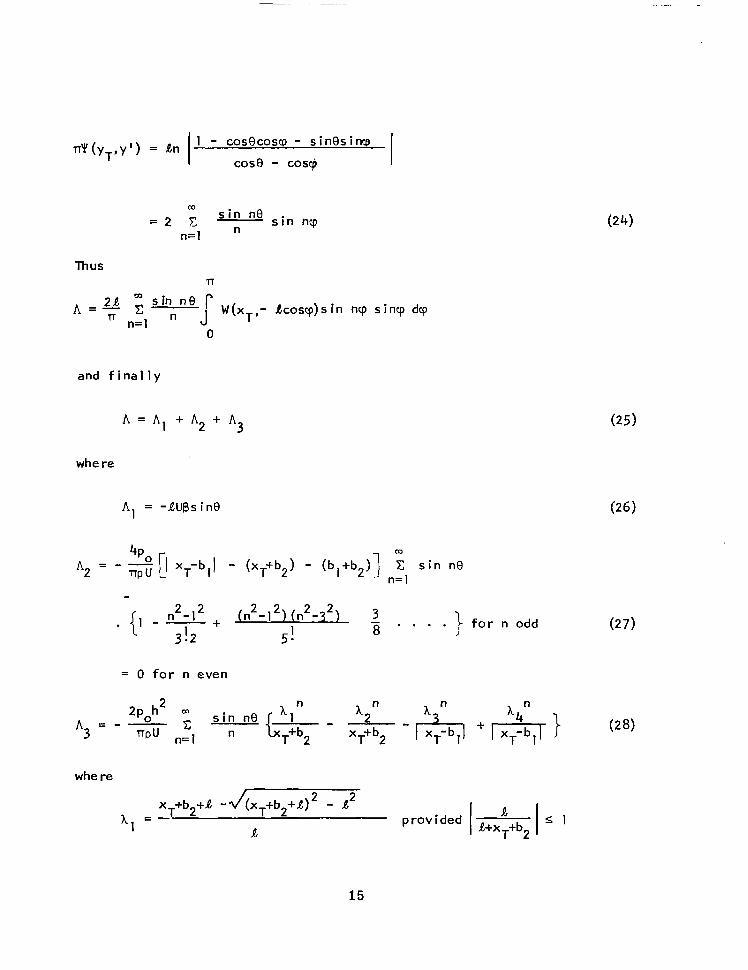
r r 'Y(YT,Y ' ) = An I cos9 - cos@ I 1 - cos9cosco - sinesince
W s i n ne
= 2 c n s i n ncp n= 1
Thus rr
A = - 2~ sin n e r rr n=l
c- W(xT,- Acoscp)sin ncp sincp dcp n J
0
and f i n a l l y
A = A l + A 2 + A 3
where
A, = -XUBs i d
03
A2 = - ?G 11 xT-bl\ - (xT+b2) - (bl+b2)] 2 s i n n9 rrpu n= 1
+ (n2-12)(n 2 2 -3 3 1 5 -
- 8 . . . . 1 f o r n odd
= 0 f o r n even
whe re
x +b + A -d(xT+b2+R) - A2
a
~~ ~
T 2 hl -
- p rov i ded I R R+xT+b2
15

xT+b2-R +z/(xT+b2-A)2 - Q2 - 1 2 - p rov i ded
a
A l l the provisions are met f o r the low a s p e c t r a t i o 1 i f t i n g s u r f a c e , i . e . ,
R/b 1 . For h e i t h e r 4
o r
h4 = cos nJI n
where
p rov i ded
f o r
o r
The f i r s t condit ion for the evaluat ion o f 1 i s s a t i s f i e d 4
bl b l and - < 1 - 2 - R
"< 1 b b b
bl "> 1 b
and bl - > 1 + 2 - R b b
16

whereas the second c o n d i t i o n i s s a t i s f i e d f o r
o r
bl - e 1 b and
bl "> 1 b and
bl 2R " > 1 " b b
bl 2 1 -e 1 + - b b
Thus the va lue o f l4 has two di f ferent express ions depending on the
imposed geomet r ic cond i t ion on b o t h t h e t i r e and i t s f o o t p r i n t . The
r e a l i z a b i l i t y o f t h e imposed geomet r ic cond i t ion can o n l y be decided from
exper imental observat ions. As i s seen from Figure 12 of Reference (4) the
pneumatic t i r e keeps i t s symmet r ica l pos i t ion w i th respec t to the wheel
ax le du r ing t he en t i re p rocess f rom the s ta t i c cond i t i on un t i l t he s tage
o f complete detachment. A t the f ina l s tage the leading edge o f the
f o o t p r i n t o f t h e h y d r o p l a n i n g t i r e remains approximately a t the same
distance f rom the wheel ax le , i .e . b - b2, whereas the t r a i l i n g edge o f
t h e l i f t i n g s u r f a c e moves away from i t s o r i g i n a l p o s i t i o n towards the
wheel axle, i.e., bl > b.
Under those circumstances h4 i s g i v e n e i t h e r b y E q u a t i o n 30 when
bl/b > 1 + 2 or by Equa t ion 31 when bl/b C 1 + 2 . a b
E) Total L i f t on the Hydroplaning Tire
The t o t a l l i f t can be ca lcu lated f rom Eq. (17) a f t e r s u b s t i t u
o f Eqs. (25), (26), (27) and (28), so t h a t
I t ion
where w i t h y T = - R cos0 and dyT = R s i n0 d0 and x T = b
17

P a
P ll
Then
L e t t i n g R/b = A (aspect ra t io) then
R (A - A ) =- - 2~ JT 1 +- - ,/= b+b2 ’ I+b2/b I+b2/b 1 + b2/b
and when
(34)
or when
18

o r when
I f the 1 i f t c o e f f i c i e n t i s d e f i n e d as
c = - L
g p U2 (2b) (2A) (37)
and use i s made o f the f a c t t h a t a t the hydroplaning stage the force
exer ted on the ground must be balanced by the force exer ted on t h e t i r e ,
I .e.
" PO cL 2b 2 - - - 2 bl + b2
i P U
where the f ac to r 5 ( o f C ) i s int roduced to account for the depth
correct ion suggested by Wad1 i n and Christopher in Reference (g), then L
E q s . (33 ) t o (37) y i e l d
o r
19

whe re
1 ) for
F(A) = F~ (A) =
2 ) and f o r
F(A) = FZ(A) =
When bl < b ,
and
20

whe re
when bl/b < 1 - 2A
when b,/b > 1 - 2A
When bl > b ,
and
bl + b2
bl -b h Ab
1+ b2 bl +b2 - + (2) - F (A)
where
F1 (A) when bl/b > 1 + 2 A
F(A) =
F2 (A) when bl/b 1 + 2 A
The o r i e n t a t i o n and p o s i t i o n o f t h e p l a n i n g t i r e r e l a t i v e t o t h e
runway i s more convenient ly descr ibed in terms o f leading and t r a i l i n g
edge clearance (h and d, respec t i ve l y ) and a s p e c t r a t i o A , ra ther than
angle o f a t t a c k B and leading edge clearance h. As i s seen from Figure 36,
the angle B i n rad ians can be expressed as fol lows:
21

Equation (39) or (40) should be used in conjunct ion with (41) i n
evaluat ing the l i f t c o e f f i c i e n t i n the hydroplaning stage.
22
NUMERICAL CALCULATIONS AND DISCUSSION OF RESULTS
The purpose o f t h i s p r e l i m i n a r y i n v e s t i g a t i o n i s t o d e v o l o p a
theoret ica l approach to the. hyd rop lan ing o f a pneumatic t i r e from the
standpoint of inviscid hydrodynamics. The theory furnishes an expression
f o r the 1 i f t c o e f f i c i e n t i n terms o f the aspec t ra t io o f the wet ted por -
t i o n o f the hydrop lan ing t i re , the geomet ry o f the foo tpr in t , the shape
o f t h e d e f l e c t e d t i r e i n c o n t a c t w i t h t h e w a t e r , i t s p o s i t i o n r e l a t i v e
to the pavement, and the depth of water on the runway.
I n t h i s f i r s t a t t e m p t the we t ted po r t i on o f t he t i r e i s app rox i -
mated by a r i g i d p l a t e o f s m a l l a s p e c t r a t i o and the p ressu re d i s t r i bu t i on
on the ground f o o t p r i n t i s assumed t o be represented by a un i fo rm d is -
t r i b u t i o n i n s t e p - l i k e f a s h i o n i n b o t h d i r e c t i o n s ( l o n g i t u d i n a l and
t ransverse) w i th amp1 i tude equal to that o f the in ternal pressure o f the
pneumatic t i r e i n accordance with exper imental evidence. Thus the problem
reduces t o t h a t analogous to p lan ing o f a smal l aspect ra t io sur face on
extremely shal low water, when i t s e f f e c t on the bottom (runway) i s app rox i -
mated i n t h i s way.
A) Ef fects of Var ious Parameters
A s e r i e s o f c a l c u l a t i o n s has been performed f o r a v a r i e t y of t i r e
p o s i t i o n s r e l a t i v e t o t h e runway a t d i f f e r e n t d e p t h s o f w a t e r w i t h v a r i o u s
t i r e aspect ra t ios and f o o t p r i n t geometry. These sys temat ic ca lcu la t ions
br ing out the re la t ive impor tance o f the var ious parameters which descr ibe
the hydroplaning phenomenon from the standpoint of hydrodynamics. Further-
more, genera l ly favorable qual i ta t ive compar ison o f the resul ts wi th those
of exper iments under s im i la r cond i t ions s t rengthens the va l id i ty o f the
mathematical model and substant iates the pr imary assumption that the
problem i s a hydrodynamical one. I t should be kep t i n mind that the
r e s u l t s must be used o n l y f o r a q u a l i t a t i v e d e s c r i p t i o n o f t h e h y d r o p l a n i n g
t i re, s ince the problem has been analyzed only approximately.
23
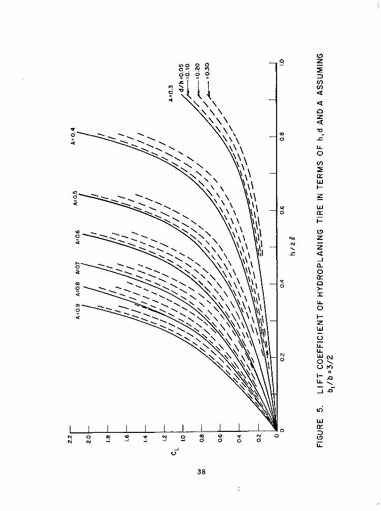
Figures 4 and 5 present the computed t o t a l 1 i f t c o e f f i - c i e n t C o f L a p l a n i n g t i r e i n terms o f depth o f water , h , fo r var ious aspec t ra t ios ,
A , and a t v a r i o u s h e i g h t s , d , o f t h e t r a i l i n g edge o f the t i r e above the
ground. The t i r e has been assumed t o be a r i g i d f l a t s u r f a c e p l a n i n g a t
a f i x e d t r i m angle defined by Equation (41). Figure 4 i s f o r a r a t i o o f
ground f o o t p r i n t a r e a t o h o r i z o n t a l p r o j e c t e d t i r e w e t t e d a r e a o f 1.17, wh i le F igure 5 i s f o r an a r e a r a t i o o f 1.25. In bo th cases i t i s assumed
that the leading edges o f t h e f o o t p r i n t and t i r e 1 i e on the same perpen-
d i c u l a r 1 ine, i.e., b2 = b whereas the t r a i l i n g edge o f t h e f o o t p r i n t
i s a f t o f the t r a i l i n g edge o f t he hyd rop lan ing t i r e . I n t he f i r s t case
bl/b = 4/3 and i n t h e second bl/b = 3/2. The curves exh ib i ted in F igures
4 and 5 can be considered to represent the boundary between the hydro-
p lan ing and non-hydroplaning regimes. In fact , they represent the 1 i f t
c o e f f i c i e n t C , a t i nc ip ien t hyd rop lan ing . Thus i f CL o f a g i v e n t i r e
c o n f i g u r a t i o n w i t h known loading and f o o t p r i n t geometry can be est imated,
then the condi t ion CL > CL ( i .e . , smal le r o r g rea ter than 1 i f t c o e f f i c i e n t
o f i n c i p i e n t h y d r o p l a n i n g ) a t a given depth of water on the runway will
determine whether o r n o t t h e t i r e will hydroplane under these Conditions.
Severa l in terest ing resul ts are ev ident f rom an examinat ion o f F igures 4 and 5 -- these are described below.
L i
< i
E f f e c t o f Aspect Ratio ( A ) : For a g iven th ickness o f water layer , h ,
and h e i g h t , d , o f t i r e t r a i l i n g edge above the runway, t h e r e i s a rap id
increase in hydroplaning 1 i f t c o e f f i c i e n t as the aspec t ra t io , A, i s i n -
creased. This e f f e c t i s p a r t i c u l a r l y e v i d e n t as the water layer th ickness
i s increased. The normal aspect r a t i o o f a i r c r a f t t i r e s i s o f the order
o f 0.75. Thus i t appears t o be o f some b e n e f i t t o reduce the t i r e aspect
r a t i o so as to ob ta in sma l le r p lan ing l i f t c o e f f i c i e n t s and hence h ighe r
speeds o f p l a n i n g i n c e p t i o n .
E f f e c t o f Water Depth (h): For a g iven aspec t ra t io and t i r e h e i g h t
above the runway, i t i s seen, in F igures 4 and 5, that the p lan ing 1 i f t
coe f f i c i en t i nc reases rap id l y w i th i nc reas ing wa te r dep th h -- t h i s i s
e s p e c i a l l y t r u e f o r t h e l a r g e r v a l u e s o f a s p e c t r a t i o . Hence, a1 1 o t h e r
cond i t ions be ing equa l , the poss ib i l i t y o f hydrop lan ing inc reases s ign i -
f i can t l y w i th i nc reas ing t h i ckness o f wa te r l aye r . Th i s conc lus ion i s no t
24

considered to be at var iance wi th the resul ts o f the exper imenta l program
descr ibed by Dugoff and Ehr l ich, " s ince there are more c o n s t r a i n t s imposed
on the theore t ica l var ia t ions than in the exper iments . The l e n g t h o f t h e
f o o t p r i n t f o r example, which appears t o have a g r e a t e f f e c t , was h e l d con-
s t a n t as h/21 was va r ied i n t he ca l cu la t i ons wh i l e i n t he exper imen ts t h i s
parameter i s necessa r i l y a l l owed to t ake on any value.
E f fec t of Tire Clearance (d) : For a g iven aspec t ra t io and water
depth, there is a r e l a t i v e l y s m a l l decrease i n 1 i f t c o e f f i c i e n t f o r r a t h e r
la rge inc reases in t i re c learance -- e s p e c i a l l y f o r h i g h a s p e c t r a t i o s
and large water depths. For example, a t water depth h /21 = .3O, and aspect
r a t i o 0.80, the 1 i f t c o e f f i c i e n t decreases only 20% f o r a 500% increase
i n ground clearance (from d/h = 0.05 t o d/h = 0.30). Since the hydroSLaning
speed var ies inverse ly as the square roo t o f the p lan ing 1 i f t c o e f f i c i e n t ,
the speed o f i n c i p i e n t h y d r o p l a n i n g will increase only about 10% f o r a
500% increase in g round c learance, a l l o ther fac to rs be ing equa l . For a
g iven set o f env i ronmenta l condi t ions then, these resul ts ind icate that
the 1 i f t c o e f f i c i e n t will be near ly constant dur ing hydroplan ing.
*-
To i l l u s t r a t e t h i s p o i n t f u r t h e r , F i g u r e s 6 and 7 have bee prepared
t o show the re la t i ve impor tance o f t i r e c lea rance and water depth on C
For a wide range o f a s p e c t r a t i o s i t i s seen tha t , t o ma in ta in a constant
C o f e i t h e r 0.7 o r 0.8, a 500% increase in t i re c learance d /h corres-
ponds t o o n l y a 10-15% increase in water depth h/2R o r a 5-10% decrease
in wet ted a rea o f the t i r e . T h i s i n d i c a t e s t h a t once t i r e hydroplan ing
occurs i t i s r a t h e r i n s e n s i t i v e t o ground clearance so t h a t a n e a r l y con-
s t a n t CL r e s u l t s f o r a given h and A. In fact , exper imenta l data (Ref .
4,5) and two-dimensional theory (Ref. 1 ) do ind ica te an essent ia l l y cons tan t
CL dur ing hydrop lan ing fo r a wide range o f d/h values.
L'
L
E f f e c t o f F o o t p r i n t / T i r e p r i n t Area Rat io (b l /b) : F igure 4 presents
r e s u l t s f o r b l / b = 4/3 wh i le t he resu l t s i n F igu re 5 a r e f o r b,/b = 3/2. I t i s i n t e r e s t i n g t o n o t e t h a t as the t r a i l i n g edge o f t h e f o o t p r i n t moves
f a r t h e r a f t (bl/b increasing) C, decreases or hydrop lan ing speed increases.
A lso the fami ly
o f water on the
aspec t ra t i o .
L
of parametr ic curves is "s t re tched" towards greater depth
runway and t h e s t r e t c h i n g i s more pronounced w i th sma l le r
25

I t i s i n t e r e s t i n g t o compare the resu l t s o f t he p resen t ana lys i s
w i th the exper imenta l resu l ts o f Chr is topher (Ref . 10) who studies the
e f f e c t o f s h a l l o w w a t e r on the hydrodynamic character ist ics of a f l a t
p lan ing sur face . Among h is exper imenta l con f igura t ions those w i th c lear -
ances d/2R = 0.20 t o 0.25, f o r a range o f A, are selected for comparison
wi th the present theory because they represent more c lose ly t he cond i t i ons
o f the mathematical model. The t h e o r e t i c a l c a l c u l a t i o n s were performed
f o r v a l u e s o f b /b = 2 based on Chr is topher 's exper imenta l observat ion
that the roach of the wake moves a f t o f the t r a i l i n g edge o f t h e f l a t
p l a t e as the depth o f the water is increased. As i s seen from Figure 1 1
o f Ref. 10, the roaching o f the stream1 ine a f t o f the t e s t model i s accom-
panied by a pronounced trough which, i n t u rn , i nd i ca tes t he ex ten t o f t he
h igh p ressure reg ion a f t o f the sur face . I t i s b e l i e v e d t h a t t h e wake
o f a f l a t p l a n i n g s u r f a c e i n s h a l l o w w a t e r will extend much f a r t h e r a f t
t han t ha t o f a t i r e w i t h the same a s p e c t r a t i o and w i t h i t s c h a r a c t e r i s t i c
curvature when hydroplan ing in ext remely shal low water . The comparison
w i t h t h e o r e t i c a l r e s u l t s i s e x h i b i t e d i n F i g u r e 8. I t i s seen tha t theory
and e x p e r i m e n t a r e i n s a t i s f a c t o r y agreement fo r sma l l va lues o f A up t o
0 . 4 f o r t h e e n t i r e range o f h/2R. As A increases, the reg ion o f favorable
agreement moves towards smal l e r values o f h/2R. However, i t should be
noted that i f a h igher va lue o f b l /b had been taken fo r the h igher aspec t
r a t i o range, the agreement would have been b e t t e r .
1
B) i ncept ion o f Hydrop lan ing
The prev ious resu l ts can be used to p red ic t hydrop lan ing incept ion
speeds. Equating the integrated pressure load on the runway t o the in te-
grated pressure load on the t i re
C po(bl + b2)2R = 4 pU2 $ ' 2b ' 2R
r e s u l t s i n
&- "incept ion
cL
- -
26
where po i s the t i r e p r e s s u r e i n l b / f t 2 , K = (bl + b2)/2b, p/2 M 1 .
For given values of environmental condit ions, i .e., , h, A , K, it has been p r e v i o u s l y shown exper imenta l l y , tha t CL i s e s s e n t i a l l y c o n s t a n t
so tha t the incept ion speed o f p lan ing i s p ropor t i ona l t o t he square roo t
o f t i r e p r e s s u r e . T h i s r e s u l t i s i n accordance w i th the exper imenta l
observat ions of Reference (4',5). Theore t ica l l y , however, the constancy
o f C. f o r a l l c o n d i t i o n s cannot be expla ined as y e t . L i
To
the plan
reported
"~ "
T i re No.
" - - "
l a
l b
2
3 4
5a
5b
5c
6a
6b
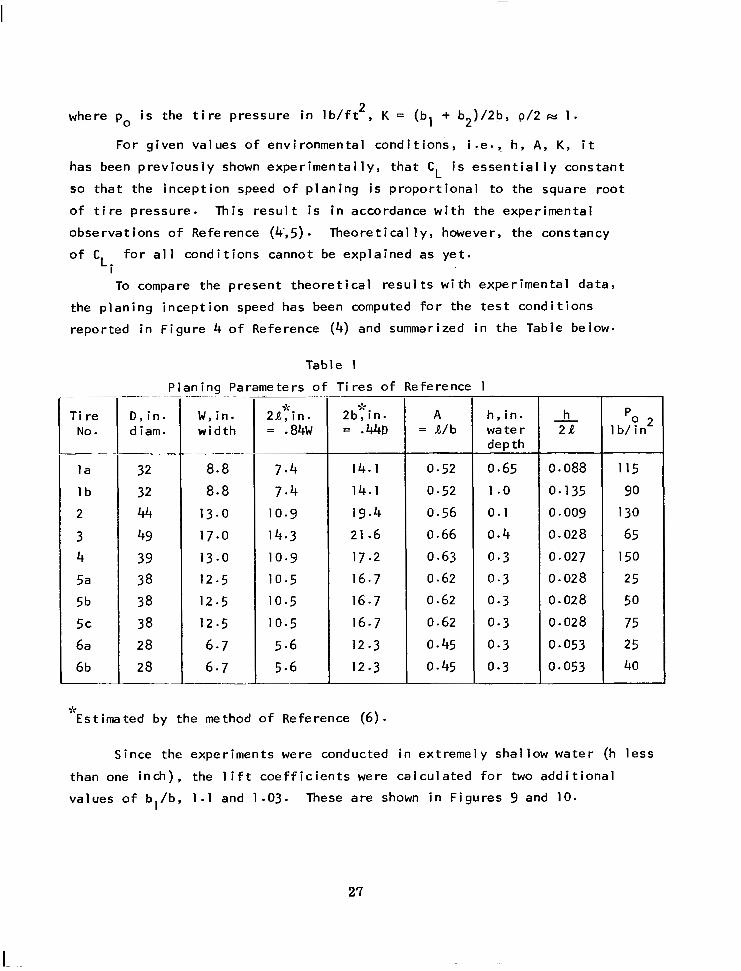
compare the p resen t t heo re t i ca l resu l t s w i th
ing incept ion speed has been computed fo r t he
i n F i g u r e 4 o f Reference (4) and summarized
Table 1
Planinq Parameters o f T i r e s o f Reference
experimental data,
t e s t cond i t ions
i n t h e Table below.
- "~ ~~ ~
W , i n . w i d t h
~ ~
8.8 8.8
13.0
17.0
13.0
12.5
12 - 5 12.5
6 - 7 6.7
"
"r
2~: ' i n . = .84W
7 - 4 7.4
10.9
14.3 10.9
10.5
10.5
10.5
5 - 6 5.6
2bTin. = .&D
14.1 14.1
19.4 21.6
17.2
16.7 16.7 16.7 12.3
12.3
9: Estimated by the method o f Reference (6).
A = R/b
0.52
0.52
0.56
0.66
0.63
0.62
0.62
0.62
0.45
0.45 ~~
1
h, in. wa t e r depth
0.65
1 .o 0.1
0.4
0.3
0.3
0.3
0.3
0.3
0.3
- h 2 a
0.088
0 - 135 0.009
0.028
0.027
0.028
0 - 028
0.028
0 * 053
0.053
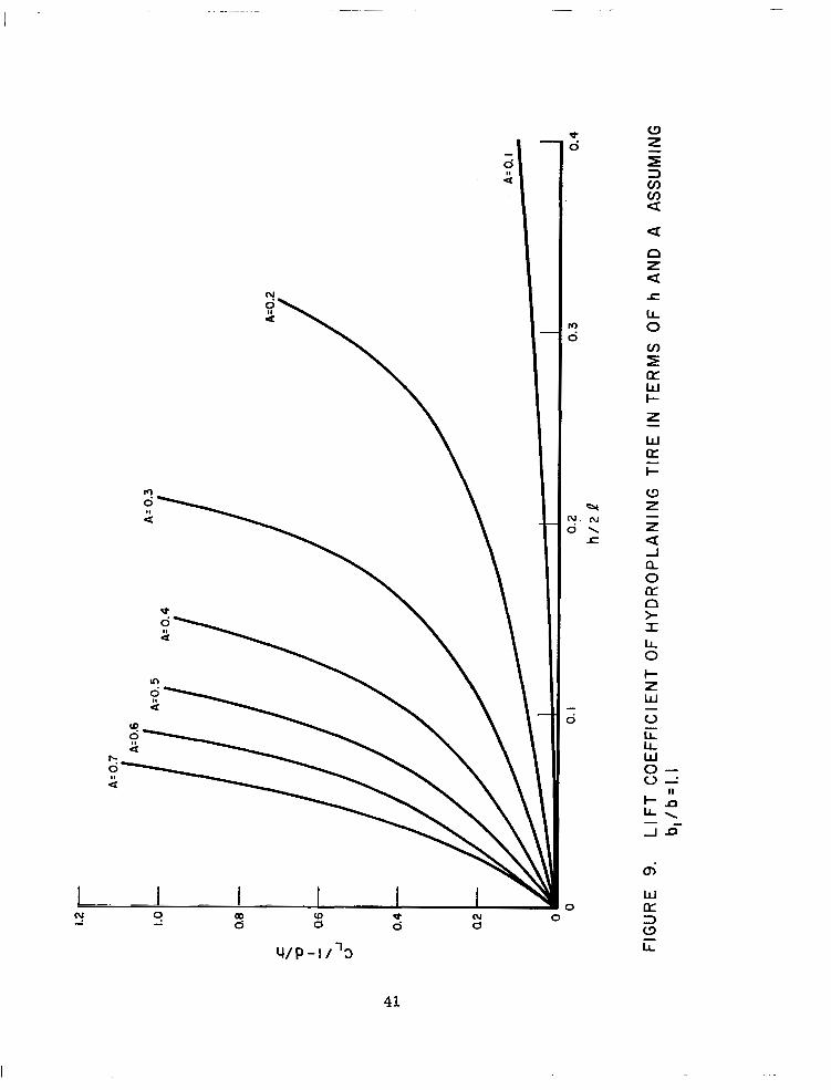
Since the experiments were conducted in ext remely shal low water (h l ess
than one inch), the 1 i f t c o e f f i c i e n t s were c a l c u l a t e d f o r two a d d i t i o n a l
va lues o f b l /b , 1 . 1 and 1.03. These are shown i n F i g u r e s 9 and 10.
27
I

The va lues o f es t imated hydrop lan ing incept ion speed U. a re compared I
below wi th the exper imental values reported in Reference (4).
T i r e No.
l a
I b
2
3 4
5a
5b
5c
6a
6b
Table 2
Experimental Ui and Ui Estimated by the Present
Theory f o r bl/b = 1 . 1 and bl/b = 1.03
0 i n .
32
32
44
49 39 38 38 38 28
28
W i n -
8.8 8.8
1 3 . 0
17.0
13.0
12.5
12.5
12.5
6.7 6 - 7
Ui f t / s e c exP
160
132
175 120
200
67 100
120
86 100
I - Ui , f t / sec , b,/b = 1 . 1
236
1 1 1
808
3 04
473 1 93 2 73 334 1 93 2 44
estimated from b,/b = 1.03
“r
“Cannot be est imated f o r these combinations of bl/b, A and h/2R.
This compar ison ind icates that wi th a p roper cho ice o f b /b 1 i t i s p o s s i b l e t o o b t a i n the experimental speed of hydroplan ing incept ion.
I t is apparent that b /b i s a very dec is ive parameter fo r the descr ip t ion
o f the mathematical model, and furthermore that bl/b must be a f u n c t i o n
of depth h o f the water f i l m on the runway, t i r e c lea rance , d , speed o f ad-
vance ,e tc . As the depth decreases, b l approaches b; i n o t h e r words, the
a r e a o f ground pressure comes c loser to the wet ted area o f the hydroplan ing
t i r e .
1
The resu l ts p resented in Tab le 2 c o n f i r m a g a i n t h e v a l i d i t y o f
the bas ic assumpt ion that the hydroplan ing t i re phenomenon can be s tud ied
f rom the s tandpoint o f inv isc id hydrodynamics. However, t hey a l so po in t up
28

the shortcomings o f the present approximate theory i n i t s i n a b i l i t y t o
speci fy b l /b . I t could be argued that the agreement i s f o r t u i t o u s and
therefore the resul ts should be used on ly fo r gu idance and q u a l i t a t i v e
d e s c r i p t i o n o f t h e phenomenon. I t i s des i rab le there fore to ex tend the
p resen t s tudy o f t he hyd rop lan ing t i r e so as to eva lua te accura te ly the
th ree-d imens iona l hydrodynamic e f fec t in th is phenomenon.
29

CONCLUS IONS
An approximate theory has been developed for studying the hydro-
p l a n i n g t i r e by consider ing i t as a p lan ing sur face o f smal l aspec t ra t io
in ext remely shal low water . The resu l ts ob ta ined on the bas i s o f t h i s
approx imat ion exh ib i t hydrodynamic behav io r s im i la r to tha t o f a hydro-
p lan ing pneumat i c t i r e and f u r n i s h some q u a l i t a t i v e guidance f o r a v o i d i n g
th is undes i red cond i t ion .
The present approx imate theory ind icates that the phenomenon o f
hydrop lan ing o f a t i r e can be descr ibed f rom the s tandpoint o f inv isc id
hydrodynamics. The analys is furn ishes fami l ies o f curves which determine
the boundary between the hydroplaning and non-hydroplan ing condi t ion,
depending on the geometry o f t h e p l a n i n g s u r f a c e , i t s p o s i t i o n r e l a t i v e
t o the runway, the geometry o f the f o o t p r i n t p r e s s u r e d i s t r i b u t i o n and
the depth o f w a t e r on the runway. These curves which can be considered
to rep resen t " i nc ip ien t hyd rop lan ing " es tab l i sh c r i t e r i a f o r avo id ing
the undesi red hydroplan ing condi t ion. Theory ind icates spec i f ica l ly that :
a) Avoidance o f hydrop lan ing i s ex tended to h igher depth o f
water fo r smal le r aspec t ra t ios , whereas fo r h igh aspec t
ra t i o hyd rop lan ing can be avoided on ly for smal ler depths.
b) Constancy o f t h e 1 i f t c o e f f i c i e n t can be ob ta ined w i th a
l a rge number o f combinations o f aspec t ra t i os , dep th o f
water on the runway and clearance (gap) o f t he t ra i 1 ing
edge o f the 1 i f t ing surface from the ground.
c) Increas ing va lues o f c learance (gap) y ie ld decreas ing va lues
o f C L *
d) Even when the re i s a d ras t i c i nc rease i n va lues o f c lea rances
the 1 i f t c o e f f i c i e n t remains constant with unnoticeable
changes o f t he we t ted po r t i on o f t he pneumat i c t i r e o r dep th
o f w a t e r on the runway.
30
.

e) As the hor izon ta l d i s tance o f the t ra i 1 ing edge o f the
h y d r o p l a n i n g t i r e moves c loser to the perpend icu la r
th rough the ax le , the poss ib i l i t y o f avo id ing the hydro-
p lan ing cond i t i on i s ex tended to h ighe r dep th o f wa te r .
In te rpre t ing these resu l ts f rom the v iewpo in t o f speed a t which
hydroplan ing s tar ts y ie lds the fo l lowing fundamenta l conc lus ions:
a) The inc ip ien t hyd rop lan ing speed Ui decreases w i th i nc reas ing
aspec t ' r a t i o o r i nc reas ing dep th o f wa te r . A given large
value of U i s a t t a i n e d e i t h e r by s m a l l e r a s p e c t r a t i o a t
l a r g e r d e p t h o f w a t e r o r l a r g e r a s p e c t r a t i o a t s m a l l e r d e p t h
o f wa te r .
i
b) Increasing values of c learance (gap) y ie ld increasing values
o f speed o f i n c i p i e n t h y d r o p l a n i n g .
c) Hydroplan ing o f a t i r e can be delayed o r avoided by increas ing
Ui which can be achieved by decreasing the aspect rat io of the
wetted surface.
F i n a l l y , i t should be emphasized tha t the resu l ts must be used
merely as a q u a l i t a t i v e d e s c r i p t i o n o f t h e h y d r o p l a n i n g t i r e , since the
problem has been analyzed only approximately on the basis o f two assump-
t ions : a ) the wet ted sur face o f the t i re i s a low a s p e c t r a t i o p l a n i n g
surface and b) t he p ressu re d i s t r i bu t i on on the ground can be approx i -
mated by a un i form s tep- funct ion.
For fu tu re s tud ies i t i s recommended to undertake the task of
evaluat ing accurate ly the three-d imensional hydrodynamic e f fect in the
hyd rop lan ing o f t he t i r e be fo re a t tempt ing t o i nco rpo ra te t he e las t i c i t y
o f the t i re in the mathemat ica l model . I t would a lso be advisable, as a
check on the theory, to conduct a s e t o f e x p e r i m e n t s w i t h r i g i d f l a t
p la tes t o s imu la te t he f l a t -p la te p lan ing cond i t i ons t rea ted t heo re t i -
ca l l y . Th is can be done a t Davidson Laboratory on the ex is t ing s imulator
f o r t e s t i n g t i r e s i n t h e h y d r o p l a n i n g s t a g e .
31
ACKNOWLEDGEMENT
The authors are indebted to Mr. Danie l Savi tsky, Manager of the
Applied Mechanics Group o f Davidson Laboratory, for his valuable suggestions.
32
REFERENCES
1.
2.
3.
4.
5.
6.
7.
8.
9.
Martin, C.S.: "Hydrodynamics of T i r e Hydroplaning," NASA CR-601, September 1966
Moore, D.F.: "A Study o f T i r e - S u r f a c e I n t e r a c t i o n f o r t h e Case o f R o l l i n g on a Wet Surface," Cornel1 Aero. Lab. Report YD-1969-V-2, 1965
Gross, W.A., Stahler, A. and Wildman, M.: "A Comparison o f Charac- t e r i s t i c s of Se l f -Ac t ing Fo i l Bear ings and Pneumatic Tires," Ampex Report RB 65-32, 1965
Horne, W.B. and Dreher, R.C.: "Phenomena of Pneumatic T i r e Hydro- planing, '' NASA TN D-2056, November 1963
Smiley, R.F. and Horne, W.B.: "Mechanical Properties of Pneumatic T i r e s wi th Special Reference to Modern A i r c ra f t T i res , " NASA TR- R-64, 1960
Tsakonas, S. and Henry, C.J.: " F i n i t e Aspect Ratio Configurations i n a Free Surface Wave System," DL Report 1 1 18, June 1966
Watkins, C.E., Woolston, D. and Cunningham, H.: "A Systematic Kernel Function Procedure for Determining Aerodynamic Forces on O s c i l l a t i n g o r Steady F i n i t e Wings a t Subsonic Speeds," NASA TR-R-48, 1959
Wadlin, K.L. and Christopher, K.W.: "A Method f o r C a l c u l a t i o n o f Hydrodynamic L i f t f o r Submerged and P lan ing Rec tangu lar L i f t ing Surfaces," NASA-TR-R-14, 19%
10. Christopher, K.W.: "Ef fect o f Shal low Water on the Hydrodynamic Charac te r i s t i cs o f a Flat-Bottom Planing Surface," NACA Tech. Note 3642, Apr i 1 1956
1 1 . Dugoff, H . and Ehr l ich, R., "Laboratory-Scale Model Experiments t o Invest igate A i rcraf t T i re Hydroplan ing," Proceedings o f the 7 th Annual Conference on Environmental Effects on A i r c r a f t and Propuls ion Sys terns, September 1967.
33

. . .. " . . .. . . . . . .. . . . ...

FIGURE I- PNEUMATIC TIRE AT HYDROPLANING STAGE
FIGURE 2. HYDRODYNAMIC EQUIVALENT OF HYDROPLANING TIRE
35

P 2 b d _ l
t z h
+TIRE-FOOT PRINT+
SPANWISE PRESSURE DISTRIBUTION ON GROUND PLATE 7
-PLANING T IRE , [TIRE-FOOT PRINT
I J
k p o 4 rCHORDWlSE PRESSURE
DISTRIBUTION ON GROUND P L A T E
FIGURE 3A. REPRESENTATION OF SIMPLIFIED MATHEMATICAL MODEL
FIGURE 3B. POSITION OF PLANING SURFACE RELATIVE TO RUNWAY
36

A10
.9
0.8
0.7
0.6
0; 5
1.4
1.2
CL
1.0
W 4
OB
0.6
0.4
0.2 n "0
0.2
0.4
0.
6
h/z
P
0.8
I .o
FIG
UR
E
4.
LIF
T C
OE
FFIC
IEN
T O
F H
YD
RO
PLA
NIN
G TI
RE
IN
TE
RM
S O
F h,
d AN
D A
AS
SU
MIN
G
bl/ b
=4
/3
I
2.2 r 0
0.2
A.0
.9
A-0
.8
k0
.7
A-0
.6
A= 0
.5
0.4
h/e
Q
FIG
UR
E
5.
LI F
T C
OE
FFIC
b,
/ b =3
/2
IEN
T O
F H
YD
RO
PL
AN
ING
T
A=
0.4
i
0.6
0.8
I .o
'IRE
IN T
ER
MS
OF
h,d
AN
D A
A
SS
UM
ING

W
CD
d/h
A-0
.4
A.0
.3
A-0
.2
FIG
UR
E 6
. C
LEA
RA
NC
E d
IN T
ER
MS
OF
h AN
D A
FOR
CO
NST
AN
T C,
AN
D b
l/b
=4
/3
-
h/2
P
FIG
UR
E 7.
C
LEA
RA
NC
E d
IN T
ER
MS
OF
h A
ND
A F
OR
CO
NST
AN
T C,
AND
b,/
b=
3/2

r
FIGURE 8. COMPARISON OF THEORETICAL LIFT COEFFICIENTS FOR b , / b = 2 WITH EXPERIMENTAL DATA FOR FLAT PLANING SURFACES (REF. 10 1
40
A: 0.7
A: 0.3
I
0.8 -
A.0
.2
a6 -
A= 0. I
I 0
0.2
h/2
Q 0.3
0.4
0. I
FIG
UR
E
9.
LIF
T C
OE
FF
ICIE
NT
OF
HY
DR
OP
LAN
ING
TIR
E IN
TE
RM
S O
F h
AN
D A
A
SSU
MIN
G
b,/
b=
l.I

3.c
0
A:O.
4
0.0 I
0.02
0.03
h/ 2
P
0.0 4
0.
0 5
FIG
UR
E IO.
LIF
T C
OE
FF
ICIE
NT
OF
HY
DR
OP
LAN
ING
TIR
E IN T
ERMS
OF
h A
ND
A A
SSU
MIN
G
bl/ b =1.03

"
APPENDIX A
The so
f(z) =
lution of the integral equat ion
is known in the literature. For the sake of completeness of this
study, however, a derivation of the solution is presented here which
was independently arrived at by the authors.
The form of the kernel function in Eq. ( A - I ) suggests integra-
tion by parts. This yields
With the assumption that
which, in fact, corresponds to the desired tip conditions, the result
i s
-R
The auxi 1 iary condition
- a - 1,
resulting from the assumed tip condition ( A - 2 ) secures a unique solution
of the integral equation ( A - 3 ) with Cauchy-type singular kernel. The solution is given by
or
A - l

Since interchanging the order of integrat ion i s permissible for a
Cauchy kernel , the z - i n t e g r a t i o n i s performed f i r s t :
Hence, Eq. ( A - 4 ) reduces t o
A-2

APPENDIX B
When the low aspect ra t io assumpt ion is abandoned, t h e i n t e g r a l
equat ion ( 9 ) will be shown t o reduce to the Fredho lm in tegra l equat ion
o f t h e second k i nd.
The in teg ra l equa t ion can be w r i t t e n as
I f t h e i n n e r i n t e g r a l i s i n t e g r a t e d b y p a r t s b y i d e n t i f y i n g
u = x - 5
and dv = L(<,q)d< 2 / ( X - 5 l 2 + (Y-17I2
so t h a t e
then i t becomes
The in teg ra l equa t ion can then be wr i t ten as
M u l t i p l y i n g b o t h s i d e s o f Eq. B-3 by the $- funct ion (see Eq. 16) and
i n t e g r a t i n g w i t h r e s p e c t t o y ' o v e r t h e range -,e t o L y i e l d s
a
- & - a -b
B-1

which is the Fredholm integra l of t h e second kind where
k
and L ' (< ,TJ ) i s t h e unknown funct ion to be determined.
B -2


![Hydroplaning during Steady-State Cornering Maneuversedccorp.com/library/HveWpPdfs/HVE-WP-2011-3.pdf · Hydroplaning research has involved both theoretical [1-3] and experimental [4-10]](https://static.fdocuments.in/doc/165x107/5c29a11a09d3f240638cadd4/hydroplaning-during-steady-state-cornering-hydroplaning-research-has-involved.jpg)