Hydrodynamic Analysis of Binary Immiscible Metallurgical Flow … Physics A.pdf · Hydrodynamic...
25
Hydrodynamic Analysis of Binary Immiscible Metallurgical Flow in a Novel Mixing Process - Rheomixing H. Tang 1,2,∗ , L.C. Wrobel 1 , Z. Fan 2 1 Department of Mechanical Engineering, Brunel University, Uxbridge, Middlesex, UB8 3PH, UK 2 Brunel Centre for Advanced Solidification Technology, Brunel University, Uxbridge, Middlesex, UB8 3PH, UK Abstract This paper presents a hydrodynamic analysis of binary immiscible metallurgical flow by a numerical simulation of the rheomixing process. The concept of multi-controll is proposed for classifying complex processes and identifying individual processes in an immiscible alloy system in order to perform simulations. A brief review of fabrication methods for immiscible alloys is given, and fluid flow aspects of a novel fabrication method – rheomixing by twin-screw extruder (TSE) are analysed. Fundamental hydrodynamic micro-mechanisms in a TSE are simulated by a piecewise linear (PLIC) volume-of-fluid (VOF) method coupled with the continuum surface force (CFS) algorithm. This revealed that continuous reorientation in the TSE process could produce fine droplets and the best mixing efficiency. It is verified that TSE is a better mixing device than single screw extruder (SSE) and can achieve finer droplets. Numerical results show good qualitative agreement with experimental results. It is concluded that rheomixing by a TSE can be successfully employed for casting immiscible engineering alloys due to its unique characteristics of reorientation and surface renewal. PACS: 47.11.+j; 68.05.Gh; 83.50.Xa
Transcript of Hydrodynamic Analysis of Binary Immiscible Metallurgical Flow … Physics A.pdf · Hydrodynamic...

Hydrodynamic Analysis of Binary Immiscible Metallurgical Flow in a Novel Mixing Process - Rheomixing
H. Tang 1,2,∗, L.C. Wrobel 1, Z. Fan 2 1
Department of Mechanical Engineering, Brunel University, Uxbridge, Middlesex, UB8 3PH, UK 2
Brunel Centre for Advanced Solidification Technology, Brunel University, Uxbridge, Middlesex, UB8 3PH, UK
Abstract This paper presents a hydrodynamic analysis of binary immiscible metallurgical flow
by a numerical simulation of the rheomixing process. The concept of multi-controll is proposed for classifying complex processes and identifying individual processes in an immiscible alloy system in order to perform simulations. A brief review of fabrication methods for immiscible alloys is given, and fluid flow aspects of a novel fabrication method – rheomixing by twin-screw extruder (TSE) are analysed. Fundamental hydrodynamic micro-mechanisms in a TSE are simulated by a piecewise linear (PLIC) volume-of-fluid (VOF) method coupled with the continuum surface force (CFS) algorithm. This revealed that continuous reorientation in the TSE process could produce fine droplets and the best mixing efficiency. It is verified that TSE is a better mixing device than single screw extruder (SSE) and can achieve finer droplets. Numerical results show good qualitative agreement with experimental results. It is concluded that rheomixing by a TSE can be successfully employed for casting immiscible engineering alloys due to its unique characteristics of reorientation and surface renewal.
PACS: 47.11.+j; 68.05.Gh; 83.50.Xa

1. Introduction Some alloys exhibit two immiscible liquid phases within a certain temperature
range. These are advanced materials suitable for superconducting devices, electrical
contacts, and bearing materials if the soft phase A is well dispersed in the solid matrix
phase B [1]. However, the different densities of these liquid phases lead, on Earth, to
the formation of two layers. This prevents the homogeneous distribution of particles
in a matrix using simple and inexpensive casting processes. Therefore, the industrial
exploitation of such alloys has also been limited so far. Immiscible alloys have been
studied intensively for the last decades, mainly focusing on two aspects: the
fundamental mechanism of secondary phase segregation/coarsening; and mixing
approaches for the fabrication process. Amongst these, the hydrodynamic behaviour
of liquid immiscible metallic alloy flows is important. The flow field of liquid
immiscible alloys includes phenomena such as nucleation, coarsening and diffusion,
Marangoni and Stokes motions, collision and coagulation. The phase diagram of the
immiscible alloy system coupled with the operating conditions, consisting of multi-
controlled processes, determine the flow features. Possible considerations for the
numerical simulation of the twin-screw rheomixing process will be discussed in
section 2.2.
Evidence shows that the solidified microstructure of cast immiscible alloys strongly
depends on the hydrodynamic behaviour of the liquids during cooling [2]. Therefore,
there is an increasing need to be able to control these complex metallurgical processes
and hence, an improved capability to numerically simulate and study these processes.
Numerical simulations are, in principle, ideally suited to study these complex
immiscible interfacial flows and to provide an insight into the process that is difficult
to obtain by experimentation.
The hydrodynamic analysis of binary immiscible liquid alloys by a numerical
evaluation presented here involves simplified problems that reflect the main flow
features in the rheomixing process. The concept of multi-controlled process is
proposed for classifying complex processes in an immiscible alloys system and
identifying individual processes. A brief review of fabrication methods for immiscible
alloys is given and fluid flow aspects of a novel fabrication method – rheomixing by a
twin-screw extruder are analysed. Fundamental hydrodynamic micro-mechanisms in

rheomixing process are simulated by a piecewise linear (PLIC) [3] volume-of-fluid
(VOF) method [4] coupled with the continuum surface force (CFS) algorithm [5].
2. Binary immiscible liquid alloys system
2.1 Rheological and thermodynamic behaviour
A miscible gap in the liquid state is found in metal-metal systems such as Al-Bi,
Al-Pb, Cu-Pb, Zn-Pb, Ga-Pb etc. A typical equilibrium phase diagram is shown in
Fig.1. The flow behaviour of the binary system is generally determined by its phase
diagram. Above the so-called critical temperature Tc, both components are completely
miscible to every amount or proportion in the liquid state. Below Tc, two liquids of
different compositions, L1 and L2, coexist in equilibrium as a two-phase liquid state.
At Tmon, liquid L1 is no longer stable and a monotectic reaction occurs, while a solid
phase SA appears in liquid phase L2. The rheological behaviour of L1 + L2 is
significant and will affect the microstructure of solidification in the final casting,
which will also be influenced by different fabrication processes [6].
The recent progress in liquid immiscible alloys has been reviewed by Ratke and
Diefenbach [2]. Zeng et al. [7] presented the computerized prediction of phase
diagrams of liquid-liquid immiscible binary systems between non-transition elements.
Good agreement is reached for a Ga-Pb binary system. Zhang et al. [8] reported a
calculation that was carried out numerically for an immiscible phase in the Zn-Pb
binary alloy system. The agreement between the calculated and experimentally
determined values of activity coefficient is excellent, indicating the validity of the
NRTL equation model for the description of immiscible solutions. Plevachuk et al. [9]
performed electroconductivity measurements for binary and ternary immiscible In¯Se,
In¯Te, Tl¯Se, Tl¯Te and Tl¯Se¯Te system alloys. Shim et al. [10] studied the liquid
miscibility gap in the Al¯Pb¯Sn system, and reported that the liquid miscibility gap
boundary of two immiscible liquids, Al- and Pb-rich, has been measured in a
temperature range between 1073 and 1293 K. A set of ternary liquid thermodynamic
parameters has been evaluated based on experimental data measured in that work,
together with phase equilibrium data available in the literature. From these, the phase
diagram of the Al¯Pb¯Sn system, including the liquid miscibility gap, has been

calculated using the CALPHAD method. The calculated results are in good agreement
with experimental data. A review of phase diagram principles and computations has
been given in [11]. Smith and Elmer [12], Gueneau et al. [13] have also presented
studies of immiscible alloys. Ratke and Alkemper [14] worked on modelling of phase
separation in liquids with a miscibility gap.
Fig. 1 Typical binary phase diagram with a miscible gap in the liquid state
2.2 The concept of multi-controlled process
The flow fields of liquid immiscible metallic alloys under conventional processes
include the effects of nucleation, coarsening and diffusion, Marangoni and Stokes
motions, collision and coagulation. However, by imposing an external mobile source
(see Fig.2), such as mechanical stirring, enhanced micro- and macro-structural flow
fields are induced, which dominate the flow features. Possible considerations are
depicted in Fig. 2. The concept of multi-controlled processes is developed comparing
with conventional processes as shown in Fig. 2. The object is to classify and identify
flow regions of immiscible liquid alloys, and determine the dominant flow in each
process that can be studied numerically for charactering the fundamental mechanisms
of rheomixing by TSE process. The important parameters or functions are shown in
Fig. 2, below the name of each process, where VGΔ -volume Gibbs free energy, σ-
interface tension, D-diffusion coefficient, T∂σ∂
-temperature-dependent interface
tension, T∇ -temperature gradient, η-shear viscosity, λ-mean distance, ρ-density, Re-
Reynolds number, γ -shear rate, δ-flow channel width. The numerical studies of the
microstructural mechanisms should comprehensively involve different numerical

approaches and modelling at each stage, according to which fluid phenomena play a
dominant role.
Fig.2 Sketch of the interdependence of conventional processes and multi-controlled
processes for the numerical simulation of immiscible liquid alloys
2.3 Dominating flow features
Marangoni and Stokes motions will dominate the flow features of immiscible
casting processes [6, 15], and will significantly affect the dispersion and distribution
of the drop phase on the quality of final casting. The investigation of Marangoni and
Stokes motions in the fabrication process is interesting, as it reveals the
microstructure mechanism of stability of the mixed phase flow.
The velocity of a drop caused by thermocapillary or Marangoni motion (Marangoni
convection) can be described by one of the following equations:
TRdTd
)ˆ)(ˆ(U
pm ∇
+−=
σηλη 222
2 (1)
where dσ/dT is the temperature dependence of the interfacial tension, λ̂ is the ratio of
the thermal conductivity of the droplet to the matrix, T∇ is the temperature gradient,
and η̂ is the ratio of the viscosity of the droplet to the matrix [2], or
rdTd
dxdT
Udmdm
mmd
m )32)(2(
2
ηηκκ
κσ
++= (2)
rkk
kU lm )32)(2(
2
211 ηησ++
∇= (3)
where k1 and k2 are the thermal conductivity of the matrix and dispersion phases,
respectively, σ∇ is the surface tension gradient, η1 and η2 represent the viscosity of
the droplet and matrix respectively [16], or finally [17]
]21212
2
122))((
)/2(3
)32(32 rgT
ThhrUm ηηρρση
ηηη−++∇⎟
⎠⎞
⎜⎝⎛∂∂
⎢⎣
⎡′+⎥
⎦
⎤⎢⎣
⎡+
−= (4)
The Marangoni number M is defined as:
M = μα
σ TLT Δ (5)
where σT is the temperature gradient of surface tension, ΔT the temperature difference
between hot and cold disks, L a characteristic length of the fluid, μ dynamic viscosity,
and α thermal conductivity. Alternative expressions are as follows:
M = μα
σ 2)/( rTT Δ∂∂ (6)
or M = 2ρνσβ rT∇
(7)
where β = constant >0 [18].
The Stokes motion of a droplet in the matrix phase can be described by [2]:
2
ˆ3/1ˆ1
29 grU
ms μ
μηρ
++Δ
= (8)
or 22 1 2 1
1 2 1
( )( )23 (3 2 )sU grρ −ρ η + η
=η η + η
(9)
Equation (9) is a well-known formula derived by the Hadamard-Rybczynski theory
[18].
Lu et al. [19] investigated the microstructure of an iron-copper binary system by
using equations (4) and (9). Nestler et al. [20] studied the Marangoni flow in a binary
monotectic alloy system by the phase-field method. Rudraiah et al. [21], Hibiya et al.
[22], Takagi et al. [23] studied Marangoni flow by using equation (5). A Marangoni
phenomenon has been investigated in space [17, 24, 25], because the Stokes motion
dominated the flow features on Earth. Rhazi et al. [26] presented their results for the
stability of free convection in a particle-fluid mixture with a free surface, using
equation (6) as one of the evaluating parameters. Rakte et al. ([27] investigated
droplet Marangoni motion in immiscible Al-Si-Bi alloys in space.
Marangoni migration is caused by the surface tension gradient of the dispersion
droplets in the matrix phase, which is related to the gradients of concentration and
temperature. The droplet tends to be moved in the direction of decreasing surface
tension. Marangoni is a surface-driven convection finally depending on the gradients
of temperature. Marangoni only occurs in thin laminar flow. The discussion of
convection effects can be described by three dimensionless numbers:
Peclet number D
rU=Pe (10)
Schmidt number Dν
=Sc
(11)
Reynolds number ν
rU=Re
(12)
where U is the particle velocity, ν is the kinematic viscosity, r is the diameter of the
particle, and D is the diffusion coefficient.
The Peclet number determines whether solute transport occurs mainly by
convection (Pe>>1) or by diffusion (Pe<<1). The Schmidt number characterises the
amount of momentum transfer, expressed by the kinematic viscosity in relation to that
of diffusional momentum transfer. For metallic liquids, the Schmidt number is of the
order Sc≈100. This means that the thermal field relaxes about 100 times faster than
the solute field. The Reynolds number divides the regimes of creeping flow (Re<1)
and turbulent flow (Re>>1) [2]. The normal approach for an immiscible liquid metal
flow is to consider it as a creeping, laminar flow in a viscous Newtonian liquid.
3. Fabrication processes A number of attempts have been made to obtain a homogeneous distribution for
various immiscible alloys, including stirring, rapid/directional solidification,
ultrasonic/magnetic vibration, powder metallurgy, and microgravity. In microgravity,
model materials also unexpectedly yielded separated phases. This is attributed to a

droplet migration mechanism (Marangoni migration), which is driven by gradients of
interfacial tension along the surfaces of droplets. These gradients relate directly to the
local temperature gradients in the matrix during cooling and solidification and are,
therefore, independent of gravity. With the results from microgravity experiments,
this mechanism was studied on a theoretical basis and models were developed. The
possibility of controlling the direction of migration and the velocity of droplets
through mastering the heat flow in molten alloys has been demonstrated. The ideal
situation would be to minimise the sedimentation caused by gravity by balancing it
with the Marangoni migration effect. If droplets reach a state of dynamic equilibrium,
then a stable dispersion in a solidifying matrix becomes attainable. This concept has
been tested and new materials, for example an aluminium alloy matrix with evenly-
distributed inclusions of lead or bismuth, are being tested as candidates for advanced
sliding bearing in car engines [6]. Unfortunately, the Marangoni migration effect
cannot be eliminated by counterbalancing the sedimentation due to orientation of
temperature gradient [15]. However, the TSE rheomixing approach, invented at
BCAST (Brunel Centre for Advanced Solidification Technology) by Fan et al. [1],
delivers a novel process concept to solve these problems for industrial applications.
Results show that the desired microstructure was achieved by the TSE process, with
fine and uniform droplets and homogeneous dispersion and stable suspension in semi-
solid metal (SSM) state for advanced sliding bearings in car engines.
In these materials the hard matrix sustains the dynamic loads from the combustion
process, while the soft inclusions provide self-lubrication. Developing this new
fabrication method into an economically viable casting process would permit the
development of more efficient engines.
3.1 Fabrication processes
Mixing two fluids consists generally of two successive processes. First, it is
necessary to break up the minor fluid particles into smaller ones; this is called
“intensive mixing”. Then, to obtain a good spatial distribution, one spreads these
particles within the matrix; this is called “distributive mixing”. These two processes
may be achieved simultaneously or stepwise. Since the beginning of the 1980s,
studies of mixing focused on low viscosity materials for which the value of the
Reynolds number was a key point: inducing turbulence was the best way to promote

blending. However, for mixing highly viscous materials, the best way to promote
mixing is to induce chaotic motion [28]. Various mixing devices were developed and
categorised as dynamic or static mixers: internal mixers, single-screw extruder, twin-
screw extruder, calendar, batch mixer, cams mixer, etc [29]. It is clear that efficient
mixing involves two aspects: folding and reorienting [30].
The casting of immiscible alloys by conventional methods does not yield materials
with the expected homogeneous particle distribution. Various fabrication methods [2,
31] for continuous or component processes were developed for experimental research
and industrial applications, including powder metal, directional solidification,
microgravity, stirring, orientating temperature gradient strip casting, rapid
solidification and rheomixing [32, 33]. Table 1 shows an overview of principles and
problems for the main fabrication methods.
Table 1. Overview of fabrication methods for immiscible alloys [1,2,31]
Fabrication Principles Problems
Powder metal method well mixed powder complex, powder oxide
Directional solidification aligned monotectic growth difficult to control, expensive
Space station eliminate g very expensive
Parabolic flight expensive
Drop from the tower reduce g
limited time
Mic
rogr
avity
Arti
ficia
l
Orthogonal electromagnetic current force balance g
Ma
mot
ion,
in
hom
ogen
eous
inhomogeneous
Mechanical break up coagulation
Ultrasonic vibration avoid coagulation Pb<1-wt% in Al-Pb
Stirr
ing
Magnetic vibration avoid coagulation inhomogeneous
Orientating temperature gradient Ma force balance g difficult to control direction
spray disperse particles/droplets
mould cooling avoid coagulation small quantity or In <30 wt % in Al-In, 4 mm thickness
coating disperse particles conflict between temperature of cohesive bonding and eutectic
Rap
id S
olid
ified
planar film forming size and surface finish, Pb<10wt% in Al-Pb
Particle centrifuging molten disperse particles complex, particle oxide
Rheomixing mixing by TSE, stablized in SSM state by the viscosity counterbalance g, Ma
simple, fine particle, uniform size, homogenous dispersion

3.2 A novel process-rheomixing by a twin screw extruder (TSE)
Research in recent decades has shown that a fine dispersion of the minority phase
particles in a hypermonotectic alloy can be obtained by rapid quenching or fast
cooling, thus passing through the miscibility gap within a second or less. However,
results show that the soft phase drops concentrate in the middle of the strip due to
Marangoni motion [15]. The processing starts from a temperature above Tc, which is
not practical for industrial applications.
Rheomixing by a TSE extruder with specially designed screw profiles [1] shown in
Fig.3 is a highly efficient process to produce fine droplets and a homogeneous
distribution. The main characteristics of the rheomixing process are:
• Size of particle: fine and uniform diameter.
• Morphology of particle: close to spherical shape.
• Dispersion of particle: homogeneous distribution.
• Suspension of particle: stable state for solidification
Fig.3 Schematic illustration of a TSE machine for rheomixing
Comparing existing fabrication processes as listed in Table 1, it can be seen that the
rheomixing process has excellent advantages, including near-net shape production,
one-step production, microstructural management, improved production efficiency,
improved property combinations, lower overall cost.
Basically, the main feature of a twin-screw extruder is a strong shear flow field
produced by co-rotating intermeshing screws [34, 35, 36]. Droplets are created in the
microscopic scale, and by the turbulent flow enhanced by mixing, swirling and
pumping actions in a macroscopic scale. The flow inside the rheomixing process is
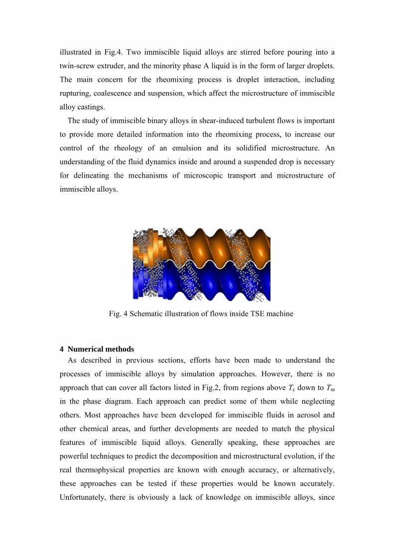
illustrated in Fig.4. Two immiscible liquid alloys are stirred before pouring into a
twin-screw extruder, and the minority phase A liquid is in the form of larger droplets.
The main concern for the rheomixing process is droplet interaction, including
rupturing, coalescence and suspension, which affect the microstructure of immiscible
alloy castings.
The study of immiscible binary alloys in shear-induced turbulent flows is important
to provide more detailed information into the rheomixing process, to increase our
control of the rheology of an emulsion and its solidified microstructure. An
understanding of the fluid dynamics inside and around a suspended drop is necessary
for delineating the mechanisms of microscopic transport and microstructure of
immiscible alloys.
Fig. 4 Schematic illustration of flows inside TSE machine
4 Numerical methods As described in previous sections, efforts have been made to understand the
processes of immiscible alloys by simulation approaches. However, there is no
approach that can cover all factors listed in Fig.2, from regions above Tc down to Tm
in the phase diagram. Each approach can predict some of them while neglecting
others. Most approaches have been developed for immiscible fluids in aerosol and
other chemical areas, and further developments are needed to match the physical
features of immiscible liquid alloys. Generally speaking, these approaches are
powerful techniques to predict the decomposition and microstructural evolution, if the
real thermophysical properties are known with enough accuracy, or alternatively,
these approaches can be tested if these properties would be known accurately.
Unfortunately, there is obviously a lack of knowledge on immiscible alloys, since

interfacial tension, viscosity, diffusion coefficients are functions of composition,
temperature, and shear rate for semisolid metals and not know with sufficient
accuracy.
4.1 Numerical approaches
Immiscible metallic alloy flows are considered here as multi-phase fluid systems in
isothermal state, with different density and viscosity. The domain of interest contains
an unknown free boundary, which undergoes severe deformation and separation. The
numerical methods adopted in the present simulations are based on Hirt and Nichols’
VOF method [4] coupled with Youngs’ piecewise linear interface construction (PLIC)
scheme [3], Brackbills’ continuum surface force (CSF) model [5], and solved by an
algebraic multigrid (AMG) solver [37], as well as the k-ε turbulence model [38] and
the pressure-implicit with splitting of operators (PISO) scheme for pressure-velocity
coupling [39]. A brief summary of the PLIC-VOF methodology is described as
follows, detailed derivations are provided in the original literature cited above.
4.2 VOF method
The principal steps of VOF methods are reconstructed interface geometry and time
integration algorithms. There are mainly three algorithms (Piecewise constant (SLIC),
Piecewise constant stair-stepped (D-A), and Piecewise linear (PLIC)) for the
reconstruction interface geometry and two algorithms (one dimensional or operator
split and multidimensional or unsplit) for time integration.
The piecewise linear method is different from piecewise constant in that it
reconstructs interface lines with a slope, which is given by the interface normal. The
interface normal is determined with a multidimensional algorithm that does not rely
on the sweep direction. PLIC volume tracking methods have been used successfully
for capturing sharp fluid interfaces. [40] [41].

4.2.1 The equation of motion The motion of the interface between two immiscible liquids of different density and
viscosity in the VOF method is defined by a volume fraction function C. The
following three conditions are possible:
C = 0 fluid 1, the cell is empty of fluid 2
(1)
C = 1 fluid 2, the cell is empty of fluid 1 (2)
0 < C <1 the cell contains the interface between the two fluids (3)
Based on the local value of C, the appropriate properties and variables are assigned to
each control volume within the domain.
The volume fraction function C is governed by the volume fraction equation
0C Ct
∂+ ⋅∇ =
∂u
(4)
where u is the velocity of the flow.
The flow is governed by a single momentum equation, as shown below, with the
resulting velocity field shared among the phases
2p g Ft
ρ μ ρ∂⎛ ⎞+ ⋅∇ = −∇ + ∇ + +⎜ ⎟∂⎝ ⎠
u u u u (5)
where F stand for body forces, and g for gravity acceleration.
The properties appearing in the momentum equation are determined by the
presence of the component phase in each control volume, that is, the average value of
density and viscosity are interpolated by the following formulas
ρ = Cm ρm + (1-Cm) ρd (6)
μ = Cm μ m + (1-Cm) μ d (7)
4.2.2 Geometric reconstruction scheme for the VOF method The formulation of the VOF model requires that the convection and diffusion
fluxes through the control volume faces be computed and balanced with source terms
within the cell itself. The interface will be approximately reconstructed in each cell by
a proper interpolating formulation, since we lose interface information when the
interface is represented by a volume fraction field.
The geometric reconstruction PLIC scheme (piecewise linear interface
construction) is employed because of its accuracy and applicability for general
unstructured meshes, compared to other methods such as the donor-acceptor, SLIC,

Euler explicit, and implicit schemes. A VOF geometric reconstruction scheme is
divided into two parts: a reconstruction step and a propagation step. The key part of
the reconstruction step is the determination of the orientation of the segment. This is
equivalent to the determination of the unit normal vector n to the segment. Then, the
normal vector n and the volume fraction C uniquely determine a straight line. Once
the interface has been reconstructed, its motion by the underlying flow field must be
modelled by a suitable algorithm [42].
4.2.3 Implementation of surface tension Surface tension along an interface arises as the result of attractive forces between
molecules in a fluid. In a droplet surface, the net force is radially inward, and the
combined effect of the radial components of forces across the entire spherical surface
is to make the surface contract, thereby increasing the pressure on the concave side of
the surface. At equilibrium in this situation, the opposing pressure gradient and
cohesive forces balance to form spherical drops. Surface tension acts to balance the
radially inward inter-molecular attractive force with the radially outward pressure
gradient across the surface. Implementation of surface tension was reviewed by
Scardovelli and Zaleski [43]. Here, the continuum surface force (CSF) model
proposed by Brackbill et al. [5] is employed. The addition of surface tension to the
VOF method is modelled by a source term in the momentum equation.
The pressure drop across the surface depends upon the surface tension coefficient
σ,
1 2
1 1( )pR R
σΔ = + (8)
where R1,R2 are the two radii, in orthogonal directions to measure the surface
curvature. In the CSF formulation, the surface curvature is computed from local
gradients in the surface normal at the interface, the surface normal n is defined by
dC= ∇ ∂n (9)
where Cd is the secondary phase volume fraction.
The curvature k is defined in terms of the divergence of the unit normal n̂ :
1ˆ ( )nk n n nn n
⎡ ⎤⎛ ⎞= ∇ ⋅ = ⋅∇ − ∇⋅⎢ ⎥⎜ ⎟⎜ ⎟⎢ ⎥⎝ ⎠⎣ ⎦
(10)

where ˆ nnn
=
(11)
The surface tension can be written in terms of the pressure jump across the
interface, which is expressed as a volume force added to the momentum equation
2 d dF kC Cσ= ∇
(12)
The CSF model allows for a more accurate discrete representation of surface
tension without topological restrictions, and leads to surface tension forces that induce
a minimum in the free surface energy configuration.
4.2.4 Solution algorithms The solution algorithm involves the use of a control-volume-based technique to
convert the governing equations to algebraic equations that can be solved numerically.
Non-linear governing equations are linearized by an implicit scheme to produce a
system of equations for the dependent variable in every computational cell. A point
implicit Gauss-Seidel linear equation solver is then used, in conjunction with an
algebraic multigrid (AMG) method, to solve the resultant scalar system of equations
for the dependent variable in each cell.
The governing equation can be discretised in the finite volume method (FVM) as
follows:
( ) ( )( )
t t t Nfaces Nfacesf f
f f f f f n ff f
V V A A S Vt φ
ρφ ρφρ φ φ
+Δ +Δ + = Γ ∇ + Δ
Δ ∑ ∑
(13)
where facesN is the number of faces enclosing a cell
fφ is the value of φ convected through face f
fA is the area of face f, ˆ ˆ( x yA A i A j= + in 2D)
( )nφ∇ is the magnitude of φ∇ normal to face f
V is the cell volume
φΓ is a diffusion coefficient for φ
Sφ is a source of φ per unit volume

A linearized form of equation (13) can be written as
p nb nbnb
a a bφ φ+ =∑
(14)
where the subscript nb refers to neighbour cells, and pa and nba are the linearized
coefficients for φ and nbφ .
The pressure-velocity coupling is achieved by using the pressure-implicit with
splitting of operators (PISO) scheme [39]. Since body forces (such as surface tension)
are to be considered in the calculation, a special treatment (body-force-weighted
scheme) is adopted to deal with the equilibrium of the body force and pressure
gradient terms in the momentum equation. This induces an extra correction in the
source term of the pressure and face flux rate equations, and the flow generally
achieves a realistic pressure field very early in the iterative process. The standard k-ε
turbulence model is employed for turbulence-imposed flows.
The computational domain in our problem requires very refined grids, because of
the need to capture the drop formation and breakup at a very fine scale. An efficient
solution is provided by the algebraic multigrid approach, which accelerates the
convergence of the solver by computing corrections on a series of coarse grid levels
when the domain contains a large number of control volumes.
5. Numerical experiments
5.1 Moving interface topologies
The moving interface cases based on the test symbol were set up to estimate the
topology of the interface during time integrations. The test symbol is initially assumed
to be a fluid (water) in air, which then falls into a shallow pool due to the force of
gravity. The computational domain is calculated on a micro-scale domain 1.6×0.4,
grid size 64×256 as depicted in Fig.5, computed by the PLIC interface reconstruction
schemes. Contours of velocity magnitude and static pressure clearly show the falling,
deforming and merging processes.

Fig. 5 Simulation results for test symbol falling into a pool in the micro-scale at
time steps: t = 0.0s, 0.004s, 0.006s, 0.008, 0.010 and 0.012s. Domain size is 1.6×0.4. From left: contour of phase interface, velocity magnitude (m/s), and static pressure (Pascal).
5.2 Rayleigh-Taylor-Instability
The nonlinear development of Rayleigh-Taylor instability is used to investigate the
interface topology and numerical convergence since this is a widely used test for
validation of the VOF method [3, 5, 40, 44, 45, 46]. In this problem, an air/helium
system in a rectangular 0.01×0.04m domain is computed to time 0.118s. Grid size is
32×128. The interface is initially a sine wave with amplitude 0.5 mm.
The results are compared with those of a high-order solver for the time integration
(LVIRA) [44] for the same mesh size (Fig. 6). Similar interface propagation is
achieved though there is a slight delay in the development of the mushroom cap. The
reconstructed interface retains all the small-scale features of the flow.
The Rayleigh-Taylor instability problem is then further propagated to time = 0.2s.
As shown in Fig. 7, the interface development is tracked properly and detailed
interface features are clearly produced. It is also noted that the characteristics of
splash are more detailed with the adaptive grid 64×256 than with the grid 32×128.

Fig. 6 Comparison of the development of the interface at different time steps with
[44] and velocity vector fields at time t=0.112s.
Fig. 7 Comparison of the topologies of the Rayleigh-Taylor unstable interface with
different grid solutions for the interface propagation from t=0 to o.12 and 0.14 to 0.2s.
6. Simulation of immiscible liquid alloy flows Here, the essential micro-mechanism of immiscible Pb-Zn liquid alloys in
rheomixing process is presented. The thermophysical properties of immiscible
metallic Pb-Zn binary alloys are taken from [47], while phase equilibrium data of Zn-
Pb binary alloys are taken from [48]. Shear rate is estimated by the equation γ = 2n π
(rs / δ –1), where rs is the screw radius, n is the screw rotation speed and δ is the gap
between barrel and screw surface [49]. Simulations are conducted on simplified flow

fields under shear-induced force, which was implemented as moving boundaries in
the computational domain coupled with imposed initial flow field condition. The
breakup scale factors (BSF) ~ ( , , )tn d pK f L L t (Ld, Lp - characteristic length scales of
daughter droplet and parent drop, respectively) are proposed here to measure the size
of the daughter drop with t = ξ, t = ψ, t = ζ the time for first daughter drop formation,
full breakup up of parent drop, and well distribution of daughter droplets,
respectively. The rotation speed for the experimental work in the BCAST laboratory
was set at 800 rpm. The status of the immiscible alloy liquid during the twin-screw
processing is controlled by a temperature control system which ensures a proper
viscosity of the matrix phase from start to finish.
6.1 Overview of immiscible liquid alloy flow in rheomixing process
The deformations of Pb metallic drops in the rheomixing process are evaluated in
simplified computational domains. The liquid immiscible metallic Pb drops break up
into small droplets in shear-induced flow, with small daughter drops forming in areas
of high local shear. The shear rate in the twin-screw rheomixing process is distributed
in the flow field with an area of high shear rate located between the flank top of the
screw and barrel wall, as well as an area located near the tip of two flights. These are
defined as one-sided shear and two-sided shear imposed flows, with a low shear rate
area in the middle of the screw channel.
The deformation of a Pb metallic drop in these areas is quite different. The Pb
metallic drop is given an initial radius rd =1, and the initial shear rate was imposed on
the flow field according to the operating condition of the rheomixing process.
The breakup scale factor (BSF) maxtK is defined as the ratio of the largest size of
daughter drop to parent drop diameter at each time interval. max max /tdd dt i
K r D=
= ,
rddmax denotes the largest daughter drop size, Dd denotes the diameter of the parent
drop.
The deformation of a Pb metallic drop in one-sided shear flow is shown in Fig.8 -
case 1. A sharp elongative end pinching was formed on the shear-induced side;
consequently, the first daughter drop formed during breakup has quite a small radius.
Later daughter drop radii are much bigger than the first few ones, and have a long rice
shape, not the near spherical shape that the first daughter drop has.
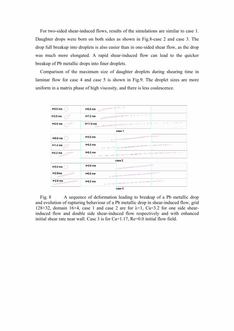
For two-sided shear-induced flows, results of the simulations are similar to case 1.
Daughter drops were born on both sides as shown in Fig.8-case 2 and case 3. The
drop full breakup into droplets is also easier than in one-sided shear flow, as the drop
was much more elongated. A rapid shear-induced flow can lead to the quicker
breakup of Pb metallic drops into finer droplets.
Comparison of the maximum size of daughter droplets during shearing time in
laminar flow for case 4 and case 5 is shown in Fig.9. The droplet sizes are more
uniform in a matrix phase of high viscosity, and there is less coalescence.
Fig. 8 A sequence of deformation leading to breakup of a Pb metallic drop
and evolution of rupturing behaviour of a Pb metallic drop in shear-induced flow, grid 128×32, domain 16×4, case 1 and case 2 are for λ=1, Ca=3.2 for one side shear-induced flow and double side shear-induced flow respectively and with enhanced initial shear rate near wall. Case 3 is for Ca=1.17, Re=0.0 initial flow field.

Fig. 9 Comparison of maximum size of daughter droplet during shearing time
in laminar flow for case 4 and case 5. Shearing time indicated in the chart starts from the time t = ψ.
6.2 Morphology of droplets flow in TSE channel and gap
The twin-screw used in the rheomixing process has a 16 mm diameter at tip and 3
mm groove with a special profile to achieve high shear rate and enhance the positive
displacement pumping action. The maximum rotation speed of the screw is designed
at 1000 rpm, which corresponds to a shear rate at 4082 s-1 in the gap between the tip
of the screw flight and the barrel [1].
The deformation is slightly different from that in the two domains corresponding to
shear-induced flow in the TSE channel and TSE gap. Due to micro-scale drop radius
and the effect of surface tension that lead to the drop maintaining a round shape, the
sharp ending deformation does not appear in the micro-scale domain. The
morphology of droplet dispersion at a later stage is relative similar in both domain
sizes as depicted in Fig.10, and the qualitative analysis of droplet dispersion on both
domain sizes will not produce significant differences.
Fig. 10 Comparison of morphology of droplet distribution in TSE channel
(left) and gap (right).

6.3 Comparison with experimental results
The numerical evolution of droplet dispersion is compared with an experimental
image [33] for the distribution of maximum droplet sizes above 32μm of diameter in
Fig.11, as the main concern in rheomixing is the maximum droplet size. It is observed
that the numerical results show good qualitative agreement with the experimental
image. The quantitative difference is shown in the graph of Fig.11. The distribution of
smaller droplet sizes is difficult to obtain due to: (1) the finest droplets were produced
by the reorientation process of TSE, however the shearing in the computational
simulation is non-reorientating; (2) the limitation of grids for the computation; the
grid would need to increase hundreds of times in order to capture a 20μm droplet. The
present numerical simulation results show that further numerical predictions can be
explored to provide a deeper insight into the microstructure mechanism of the
rheomixing process.
Fog. 11 Comparison of the droplet size distribution with experimental image
data.
6.4 Optimisation design of rheomixing process
1. Screw configuration
Generally, the right hand screw transports materials, the left hand screw controls
the pressure field, while the kneading disc melts and mixes materials. The flow
regime is envisaged as being composed of three distinct types of flow: pressure flow,
net flow and drag flow. These produce different shear rate profiles. Shear rate profiles
influence drop formation as illustrated in Fig.8. Therefore, a proper combination of
right-hand screws, left-hand screw and kneading disc is a critical factor to optimise

shear rate profiles and enhance turbulence. This means that the TSE configuration is
the most important factor to achieve the folding and reorientation actions; the
continuous reorientation in the TSE process could produce fine droplets and reach
best mixing efficiency.
2. Operating condition
a. Temperature - Control of the viscosity of the matrix phase by temperature is
important because it will balance the Stokes and Marangoni motion of droplets (that
cause sedimentation and migration, resulting in stratification and segregation in the
microstructure, respectively), which are the main obstacles to the industrialization of
immiscible alloy casting.
b. Rotation speed – The shear rate is dependent on rotation speed as mentioned in
Section 6. The shear rate will vary for different screw parameters. This includes the
screw size: pitch, left-handed helix, right-handed helix, size of kneading discs: angle,
crest width as well as the number of screws and discs, and their arrangement. The
most important phenomenum in the rheomixing process by a twin-screw extruder is
enhanced shear rate; the local shear rate could be higher than 3600 s-1. This allows
dramatic results in the dispersion and refinement of Pb liquid droplets in the Zn
matrix phase, leading to fine droplets and uniform dispersion.
3. Optimisation procedure
According to the results of numerical investigations, possible suggestions for
optimising the rheomixing process are proposed in following procedure: start shearing
immiscible metallic binary alloys under enhanced turbulence and temperature above
Tm. Both phases have the same viscosity value, which might cause fast breakup and
fine droplets, shorten the time for a full breakup, reducing power consumption. If
shearing remains at temperature Tm, this will result in spherical droplets as the
viscosity of the matrix phase is increased. Droplets will also be dispersed stably in
thick matrix phase and will be suspended homogenously in the matrix phase.
7. Conclusions The numerical simulation of the essential microscopic mechanisms of a
prototypical rheomixing process is useful for the optimisation of the rheomixing
process. The simulation model can be used to obtain an insight into shearing time,
viscosity and shear force, thus providing a guide to the operating condition of
rheomixing process in order to reduce trial and error experiments for optimising
parameters. It is concluded that rheomixing by a twin-screw extruder (TSE) was
successfully developed for casting immiscible engineering alloys due to its unique
characteristics of reorientation and surface renewal.
Acknowledgements
We acknowledge support from EPSRC grant GN/N14033, Glacier Vanderville Ltd, Ford Motor Co.
Ltd, Prism Ltd, QinetiQ Ltd. and the Mechanical Engineering Department at Brunel University. We
are also grateful to researchers in CFD group and BCAST (Brunel Centre for Advanced Solidification
Technology) for helpful discussions on numerical approaches and the TSE rheomixing casting process.
References
[1] Z. Fan, S. Ji, J. Zhang: Materials Science and Technology 17: 838 (2001) [2] L. Ratke, S Diefenbach: Material Science and Engineering RI5: 263 (1995) [3] D.L. Youngs: Time-dependent multi-material flow with large fluid distortion, In:. K.W. Morton,
M.J. Baines (eds) Numerical Methods for Fluid Dynamics (Academic Press, New York 1982) pp.273
[4] C.W. Hirt, B.D. Nichols: J Comput Phys 39: 201 (1981) [5] J.U. Brackbill, D.B. Kothe, C. Zemach: J. Comput. Phys. 100: 335 (1992) [6] ESA: The international space station microgravity: a tool for industrial research. European Space
Agency; BR-136 (1998) [7] W. Zeng, J. Guo, N. Chen, J. Guo: Calphad 21: 289 (1997) [8] Z. Zhang, Z. Su, Z. Wu, N. Chen, R. Peng: Calphad 22: 313-322 (1998) [9] Y. Plevachuk, V. Didoukh, B. Sokolovskii: Journal of Non-Crystalline Solids 250-252: 325 (1999) [10] J.H. Shim, Lee HN, H.P. Ha, Y.W. Cho, E.P. Yoon: Journal of Alloys and Compounds 327: 270
(2001) [11] J. Connolly: Phase diagram principle and computations. In: Pressure and Temperature Evolution
of Organicbelts, Lecture notes of the V summer school, The University of Siena, The Italian national Research Council, 203-220 (1992)
[12] P.M. Smith, J.W. Elmer: Acta mater. 44: 4217 (1996) [13] C. Gueneau, V. Dauvois, P. Pérodeaud, C. Gonella, O. Dugne: J Nuclear Material 254: 158 (1998) [14] L. Ratke, J. Alkemper: Advances in Colloid and Interface Science 58: 151 (1995) [15] .Z. Zhao, S. Drees, L. Ratke: . Materials Science and Engineering A 282: 262 (2000) [16] N.O. Young, J.S. Goldstein, M.J. Block: J. Fluid Mech. 6: 350 (1959), cited in [19]. [17] R.J. Naumann: Journal of Crystal Growth 154: 156 (1995) [18] Z. Zapryanov, S. Tabakova: Dynamics of Bubbles, Drops and Particles The Netherlands: Kluwer
Academic Publishers (1999) [19] X.Y. Lu, C.D. Cao, B. Wei: Materials Science and Engineering-A 313: 198 (2001) [20] B. Nestler, A.A. Wheeler, L. Ratke, C. Stöcker: Physica D: Nonlinear Phenomena 141: 133 (2000) [21] N Rudraiah, P.G. Siddheshwar: Aerosp Sci Technnol 4: 517 (2000) [22] T. Hibiya, S. Nakamura, T. Azami, M. Sumiji, N. Imaishi, K. Mukai, K. Onuma, S.I. Yoda: Acta
Astronautica 48: 71 (2001) [23] K. Takagi, M. Otaka, H. Natsui, T. Arai, S. Yoda, Z. Yuan, K. Mukai, S. Yasuhiro, N.
Imaishi: Journal of Crystal Growth 3: 399 (2001) [24] L. Ratke: Materials Science and Engineering A203: 399 (1995) [25] L. Ratke: International Journal of Multiphase Flow 22: supplement 1, 92 (1996) [26] M. Rhazi, A. Mir, Z. Zrikem, G. Gouesbet: International Communications in Heat and Mass
Transfer 23: 345 (1996) [27] L. Ratke, S. Diefenbach, S. Drees, J. Alkemper, B. Prinz, A. Romero, H. Ahlborn: Advances in
Space Research 16: 185 (1995)
[28] J.F. Agassant, A. Poitou: A kinematic approach to distributive mixing. In: I. Manas-Zloczower and Z. Tadmor (eds), Mixing and Compounding of Polymer (Hanser, New York 1994)
[29] C. Rauwendaal: Mixing in Polymer Processing (Marcel Dekker, New York 1991) [30] Meijer HEH, Janssen MH. Mixing of immiscible liquids. In: I. Manas-Zloczower, Z. Tadmor (eds),
Mixing and compounding of polymer (Hanser, New York 1994) p52, p85 [31] J. Jia, J.Z. Zhao, J.J. Guo, Y. Liu: Immiscible Alloys and Fabrication Technology (HIT, Harbin
(China) 2002) [32] Z. Fan: Twin-screw rheoforming technologies for semisolid processing of Mg-alloys. In: Y.
Tsutsui, M. Kiuchi, K. Ichikawa (eds) Proceeding of the 7th Advanced Semisolid Processing of Alloys and Composites Tsukuba 25-27 September 2002. Japan: NIAIST, JSTP, 671-676
[33] X. Fang, Z, Fan, S, Ji, Y, Hu: Processing of immiscible alloys by a twin-screw rheomixing process. In: Y. Tsutsui, M. Kiuchi, K. Ichikawa (eds) Proceeding of the 7th Advanced Semisolid Processing of Alloys and Composites Tsukuba 25-27 September 2002, Japan: NIAIST, JSTP, 695-700
[34] N.P. Cheremisinoff: Polymer Mixing and Extrusion Technology (Marcel Dekker, Inc, New York 1987)
[35] T. Avalosse: Twin screw extruder and mixing tank Presentation of Polyflow s.a., Belgium: Louvain-la-Neuve (2000)
[36] S. Bakalis, M.V. Karwe: Int. J. Food Science and Technology 32: 241 (1997) [37] K. Stüben: Journal of Computational and Applied Mathematics 128(1-2): 281 (2001) [38] B.E. Launder, D.B. Spalding: Comput. Meth. App. Mech. Engng. 3: 267 (1974) [39] R.I. Issa, A.D. Gosman, P. Watkins: J. Comput. Phys. 93: 388 (1991) [40] M. Rudman: Int. J. Num. Methods Fluids 24: 671 (1997) [41] O. Ubbink, R.I. Issa: J. Comput. Phys. 153: 26 (1999) [42] C.S. Peskin: J. Comput. Phys. 25: 220 (1997) [43] R. Scardovelli, S. Zaleski: Annu. Rev. Fluid Mech. 31: 567 (1999) [44] E.G. Puckett, A.S. Almgren, J.B. Bell, D.L. Marcus, W.J. Rider: J. Comput. Phys. 130: 269 (1997) [45] G. Černe, S. Petelin, I. Tiselj: J. Comput. Phys. 171: 776 (2001) [46] S. Guignard, R. Marcer, V. Rey, C. Kharif, P. Fraunié: Eur. J. Mech. B/Fluids 20: 57 (2001) [47] T. Iida, R.I.L. Guthrie: The Physical Properties of Liquid Metals (Oxford University Press, New
York 1988) [48] R. Hultgren, R.L. Orr, P.D. Anderson, K.K. Kelley: Selected Values of the Thermodynamic
Properties of Binary Alloys (Metals Park, ASM 1973) [49] C. Rauwendaal: Polymer Extrusion 3rd rev. ed. (Hanser, New York 1994) pp.181