HYDRO-GEAR 310-0510 INTEGRATED HYDROSTATIC …
39
HYDRO-GEAR 310-0510 INTEGRATED HYDROSTATIC TRANSAXLE MANUAL Table of Contents – Page 1 of 1 FOREWORD SECTION 1 DESCRIPTION AND OPERATION INTRODUCTION GENERAL DESCRIPTION HYDRAULIC SCHEMATIC EXTERNAL FEATURES 310-0510 MODEL RECOGNITION TECHNICAL SPECIFICATIONS PRODUCT IDENTIFICATION SECTION 2 SAFETY PERSONAL SAFETY TOOL SAFETY WORK AREA SAFETY SERVICING SAFETY SECTION 3 TROUBLESHOOTING SECTION 4 SERVICE AND MAINTENANCE EXTERNAL MAINTENANCE SERVICE AND MAINTENANCE PROCEDURES FLUIDS FLUID CHANGE PURGING PROCEDURES RETURN TO NEUTRAL SETTING BRAKE MAINTENANCE FRICTION PACK ADJUSTMENT SECTION 5 REPAIR HOW TO USE THIS SECTION GENERAL INSTRUCTIONS TRANSAXLE REMOVAL LIMITED DISASSEMBLY TOOLS AND TORQUES BRAKE ASSEMBLY AND BYPASS ARM CONTROL ARM AND FRICTION PACK SEAL KIT REPLACEMENT SIDE HOUSING AXLE SHAFT, DIFFERENTIAL AND REDUCTION GEARS MOTOR SHAFT AND BYPASS ROD INPUT SHAFT HYDRAULIC COMPONENTS TRANSAXLE INSTALLATION ASSEMBLY AFTER A COMPLETE TEARDOWN SEALANT APPLICATION 310-0710 IHT DESCRIPTION FEATURES TRANSAXLE REMOVAL PARTS LIST GLOSSARY OF TERMS
Transcript of HYDRO-GEAR 310-0510 INTEGRATED HYDROSTATIC …
HYDRO-GEAR 310-0510 INTEGRATED HYDROSTATIC TRANSAXLE MANUAL
Table of Contents – Page 1 of 1
FOREWORD
SECTION 1 DESCRIPTION AND OPERATIONINTRODUCTIONGENERAL DESCRIPTIONHYDRAULIC SCHEMATICEXTERNAL FEATURES 310-0510MODEL RECOGNITIONTECHNICAL SPECIFICATIONSPRODUCT IDENTIFICATION
SECTION 2 SAFETYPERSONAL SAFETYTOOL SAFETYWORK AREA SAFETYSERVICING SAFETY
SECTION 3 TROUBLESHOOTING
SECTION 4 SERVICE AND MAINTENANCEEXTERNAL MAINTENANCESERVICE AND MAINTENANCE PROCEDURESFLUIDSFLUID CHANGEPURGING PROCEDURESRETURN TO NEUTRAL SETTINGBRAKE MAINTENANCEFRICTION PACK ADJUSTMENT
SECTION 5 REPAIRHOW TO USE THIS SECTIONGENERAL INSTRUCTIONSTRANSAXLE REMOVALLIMITED DISASSEMBLYTOOLS AND TORQUESBRAKE ASSEMBLY AND BYPASS ARMCONTROL ARM AND FRICTION PACKSEAL KIT REPLACEMENTSIDE HOUSINGAXLE SHAFT, DIFFERENTIAL AND REDUCTION GEARSMOTOR SHAFT AND BYPASS RODINPUT SHAFTHYDRAULIC COMPONENTSTRANSAXLE INSTALLATIONASSEMBLY AFTER A COMPLETE TEARDOWN
SEALANT APPLICATION
310-0710 IHTDESCRIPTIONFEATURESTRANSAXLE REMOVAL
PARTS LIST
GLOSSARY OF TERMS
We set the wheels in motion.
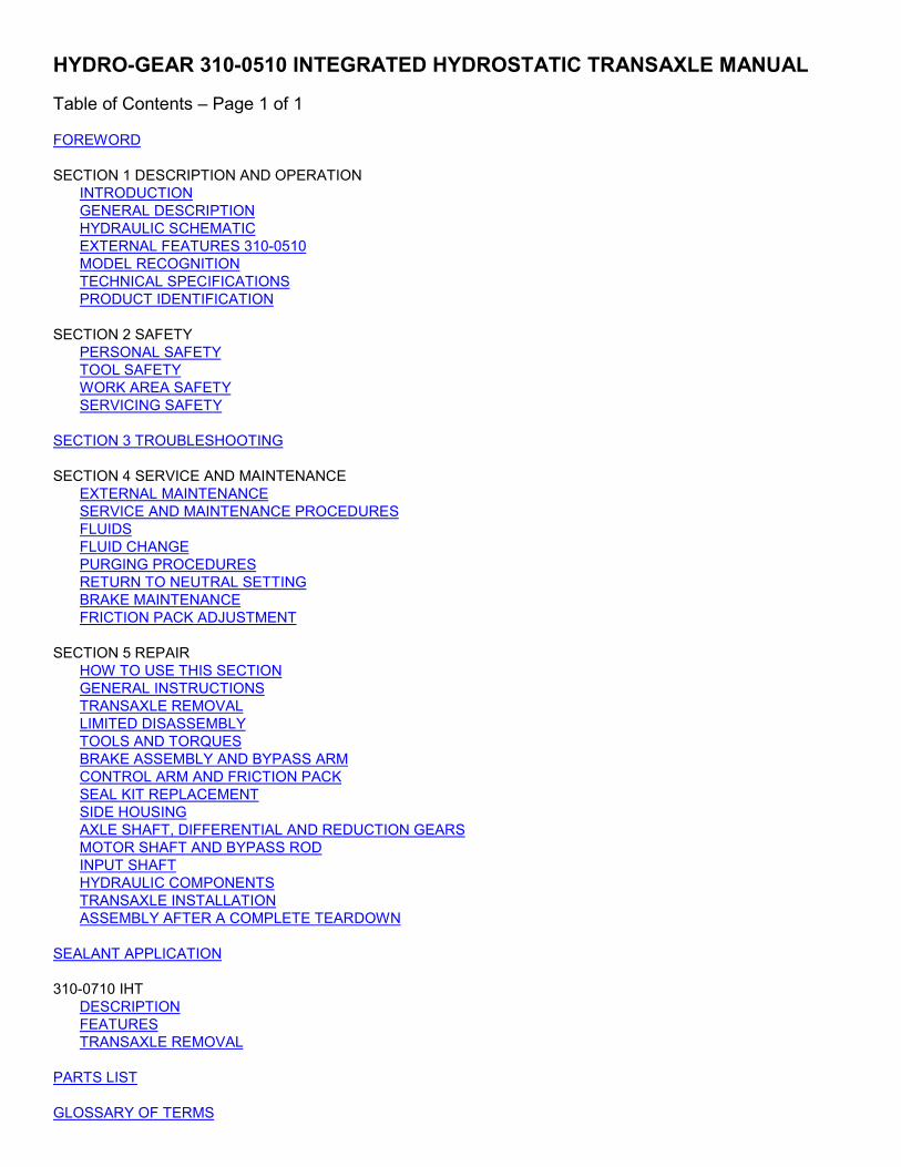
310-0510 Integrated Hydrostatic Transaxle
Service and Repair Manual BLN-51260
October 2001
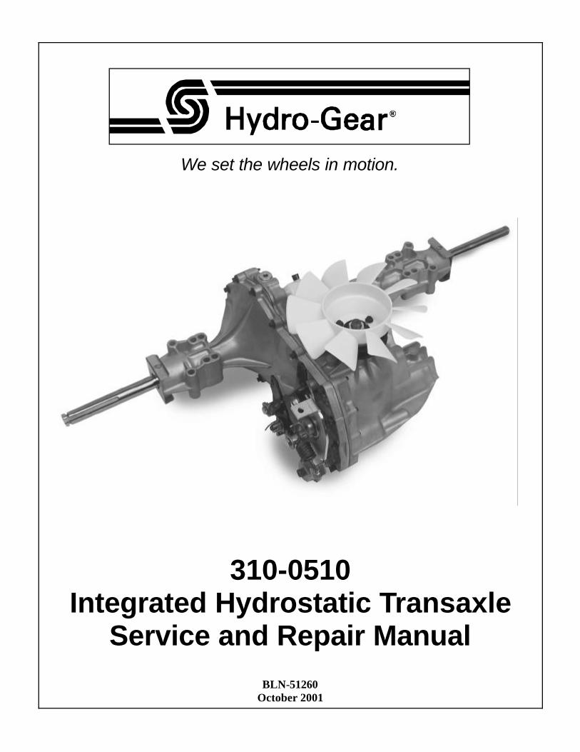
Table of Contents
Section Page Foreword ........................................................................................................................................ 1
Section 1 Description and Operation ........................................................................................... 2 Introduction ........................................................................................................................................................ 2 General Description ............................................................................................................................................ 2 Hydraulic Schematic ........................................................................................................................................... 3 External Features 310-0510 ............................................................................................................................... 4 Model Recognition .............................................................................................................................................. 5 Technical Specifications ..................................................................................................................................... 6 Product Identification .......................................................................................................................................... 6
Section 2 Safety ............................................................................................................................. 7 Personal Safety .................................................................................................................................................. 7 Tool Safety ......................................................................................................................................................... 7 Work Area Safety ............................................................................................................................................... 7 Servicing Safety ................................................................................................................................................. 7
Section 3 Troubleshooting ........................................................................................................... 8
Section 4 Service and Maintenance ............................................................................................. 9 External Maintenance ......................................................................................................................................... 9 Service and Maintenance Procedures ................................................................................................................ 9 Fluids ................................................................................................................................................................. 9 Fluid Change .................................................................................................................................................... 10 Purging Procedures .......................................................................................................................................... 11 Return to Neutral Setting .................................................................................................................................. 12 Brake Maintenance .......................................................................................................................................... 13 Friction Pack Adjustment .................................................................................................................................. 13
Section 5 Repair .......................................................................................................................... 14 How To Use This Section ................................................................................................................................. 14 General Instructions ......................................................................................................................................... 14 Transaxle Removal .......................................................................................................................................... 14 Limited Disassembly ......................................................................................................................................... 14 Tools and Torques ........................................................................................................................................... 15 Brake Assembly and Bypass Arm ..................................................................................................................... 16 Control Arm and Friction Pack .......................................................................................................................... 17 Seal Kit Replacement ...................................................................................................................................... 18 Side Housing .................................................................................................................................................... 19 Axle Shaft, Differential and Reduction Gears .................................................................................................... 20 Motor Shaft and Bypass Rod ............................................................................................................................ 21 Input Shaft ........................................................................................................................................................ 22 Hydraulic Components ................................................................................................................................ 23-26 Transaxle Installation ........................................................................................................................................ 27 Assembly After a Complete Teardown .............................................................................................................. 27
Sealant Application ..................................................................................................................... 28
310-0710 IHT ................................................................................................................................ 29 Description ....................................................................................................................................................... 29 Features ........................................................................................................................................................... 29 Transaxle Removal .......................................................................................................................................... 29
Parts List ................................................................................................................................. 30-33
Glossary of Terms .................................................................................................................. 34-35
310-0510 IHT 1
FOREWORD Headquartered in Sullivan, Illinois, Hydro-Gear is a world leader in the design, manufacture, and service of quality hydrostatic transaxles for the lawn and garden industry. The mission of our company is to be recognized by our customers and the industry as a world-class supplier and the quality leader in everything we do.
This Service and Repair Manual is designed to provide information useful in servicing and troubleshooting the Hydro-Gear 310-0510 Integrated Hydrostatic Transaxle (IHT). The Troubleshooting Manual for the 310-0510 is part number BLN-51261. Troubleshooting for the 310-0510 is further illustrated in video BLN-51368 (NTSC).
Also included is a glossary of terms that are frequently used throughout the industry and in Hydro-Gear service publications. Understand-ing terminology is very important!
It is necessary, and good shop practice, that your service area be equipped with the proper
tools and the mechanics be supplied with the latest information available. All repair procedures illustrated in this guide are suggested, but preferred methods of repair. Repair procedures require that the transaxle unit be removed from the vehicle.
This is not a certification, test or study guide for a certification test. If a technician is interested in certification they should contact an agent representing the ESA (Engine Service Associa-tion) (610) 363-3844 or their Hydro-Gear Dis-tributor. Many distributors will be hosting certification testing. These study guides will cover most of the products and manufacturers in our industry.
For more information about Hydro-Gear or our products, please contact your Central Service Distributor, or call our Customer Service Department at (217) 728-2581.
310-0510 IHT 2
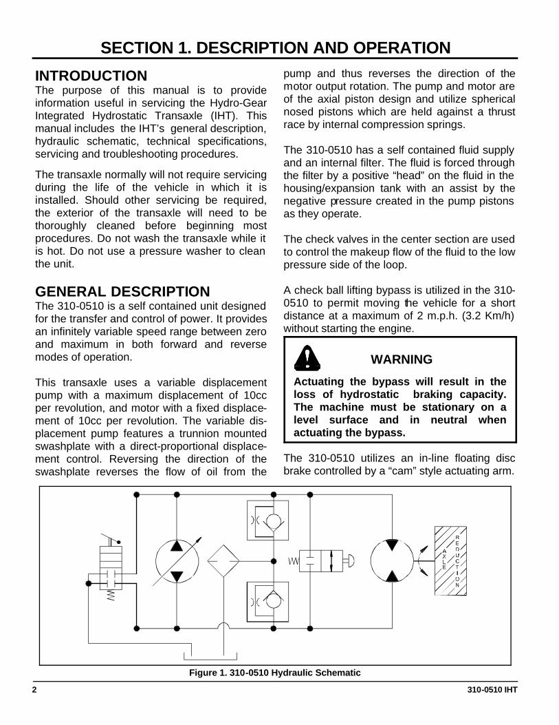
INTRODUCTION The purpose of this manual is to provide information useful in servicing the Hydro-Gear Integrated Hydrostatic Transaxle (IHT). This manual includes the IHT’s general description, hydraulic schematic, technical specifications, servicing and troubleshooting procedures.
The transaxle normally will not require servicing during the life of the vehicle in which it is installed. Should other servicing be required, the exterior of the transaxle will need to be thoroughly cleaned before beginning most procedures. Do not wash the transaxle while it is hot. Do not use a pressure washer to clean the unit. GENERAL DESCRIPTION The 310-0510 is a self contained unit designed for the transfer and control of power. It provides an infinitely variable speed range between zero and maximum in both forward and reverse modes of operation. This transaxle uses a variable displacement pump with a maximum displacement of 10cc per revolution, and motor with a fixed displace-ment of 10cc per revolution. The variable dis-placement pump features a trunnion mounted swashplate with a direct-proportional displace-ment control. Reversing the direction of the swashplate reverses the flow of oil from the
pump and thus reverses the direction of the motor output rotation. The pump and motor are of the axial piston design and utilize spherical nosed pistons which are held against a thrust race by internal compression springs. The 310-0510 has a self contained fluid supply and an internal filter. The fluid is forced through the filter by a positive “head” on the fluid in the housing/expansion tank with an assist by the negative pressure created in the pump pistons as they operate. The check valves in the center section are used to control the makeup flow of the fluid to the low pressure side of the loop. A check ball lifting bypass is utilized in the 310-0510 to permit moving the vehicle for a short distance at a maximum of 2 m.p.h. (3.2 Km/h) without starting the engine.
The 310-0510 utilizes an in-line floating disc brake controlled by a “cam” style actuating arm.
SECTION 1. DESCRIPTION AND OPERATION
WARNING
Actuating the bypass will result in the loss of hydrostatic braking capacity. The machine must be stationary on a level surface and in neutral when actuating the bypass.
Figure 1. 310-0510 Hydraulic Schematic
310-0510 IHT 3
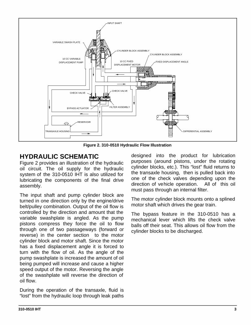
HYDRAULIC SCHEMATIC Figure 2 provides an illustration of the hydraulic oil circuit. The oil supply for the hydraulic system of the 310-0510 IHT is also utilized for lubricating the components of the final drive assembly.
The input shaft and pump cylinder block are turned in one direction only by the engine/drive belt/pulley combination. Output of the oil flow is controlled by the direction and amount that the variable swashplate is angled. As the pump pistons compress they force the oil to flow through one of two passageways (forward or reverse) in the center section to the motor cylinder block and motor shaft. Since the motor has a fixed displacement angle it is forced to turn with the flow of oil. As the angle of the pump swashplate is increased the amount of oil being pumped will increase and cause a higher speed output of the motor. Reversing the angle of the swashplate will reverse the direction of oil flow.
During the operation of the transaxle, fluid is “lost” from the hydraulic loop through leak paths
designed into the product for lubrication purposes (around pistons, under the rotating cylinder blocks, etc.). This “lost” fluid returns to the transaxle housing, then is pulled back into one of the check valves depending upon the direction of vehicle operation. All of this oil must pass through an internal filter.
The motor cylinder block mounts onto a splined motor shaft which drives the gear train.
The bypass feature in the 310-0510 has a mechanical lever which lifts the check valve balls off their seat. This allows oil flow from the cylinder blocks to be discharged.
Figure 2. 310-0510 Hydraulic Flow Illustration
INPUT SHAFT
RESERVOIR
TRANSAXLE HOUSING
CHECK VALVE
BYPASS ACTUATOR
VARIABLE SWASH PLATE
DISPLACEMENT PUMP
10 CC VARIABLE
FILTER ASSEMBLY
CHECK VALVE
DIFFERENTIAL ASSEMBLY
FIXED DISPLACEMENT ANGLE
CYLINDER BLOCK ASSEMBLY
CYLINDER BLOCK ASSEMBLY
10 CC FIXED DISPLACEMENT MOTOR
310-0510 IHT 4
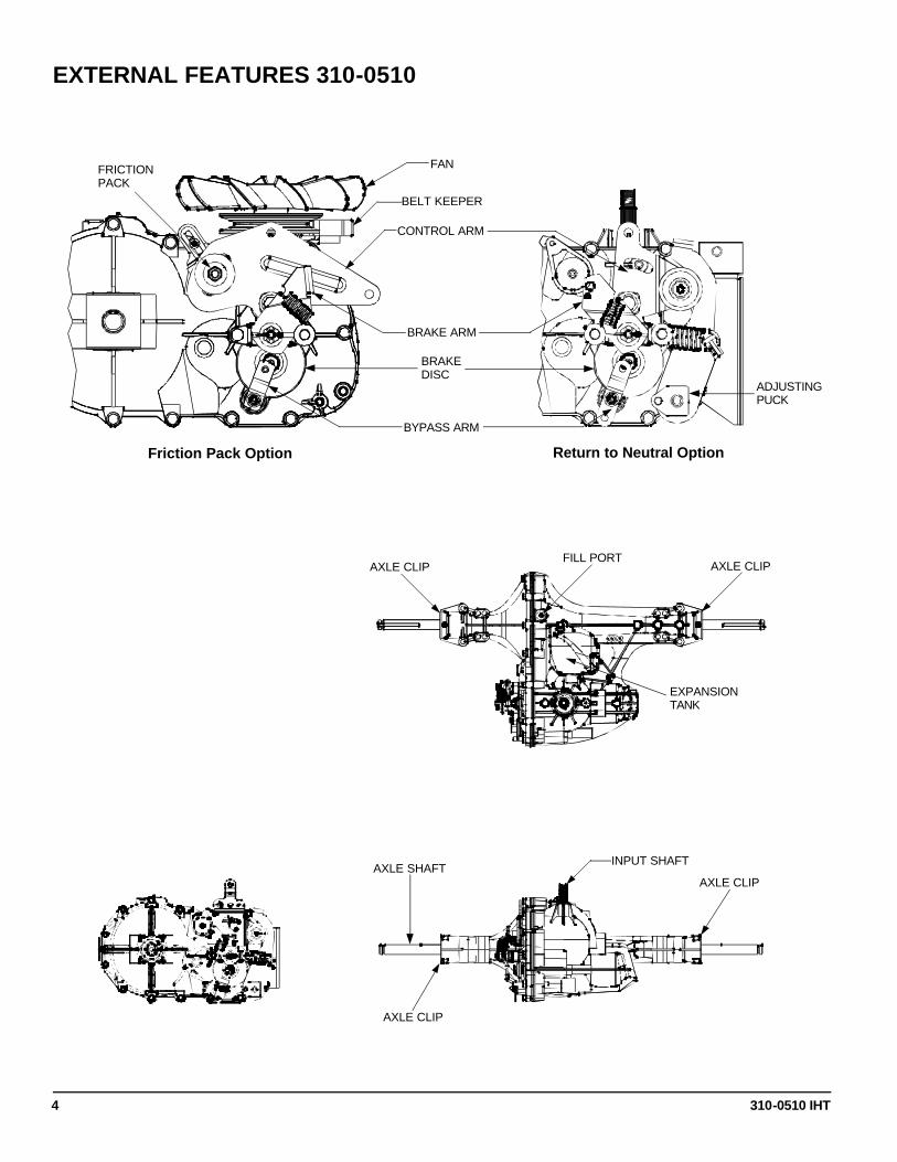
EXTERNAL FEATURES 310-0510
Return to Neutral Option Friction Pack Option
AXLE SHAFT
FILL PORT
EXPANSION TANK
INPUT SHAFT
CONTROL ARM
BRAKE DISC
FAN
BRAKE ARM
BYPASS ARM
FRICTION PACK
ADJUSTING PUCK
BELT KEEPER
AXLE CLIP
AXLE CLIP AXLE CLIP
AXLE CLIP
310-0510 IHT 5
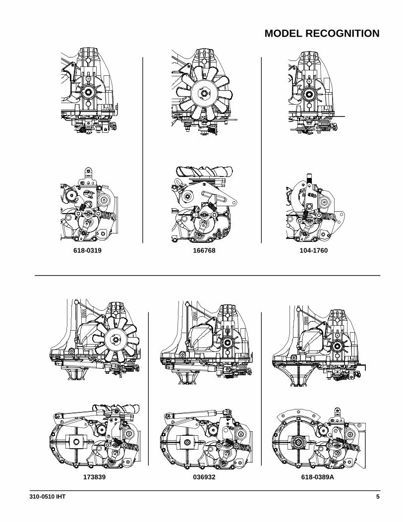
MODEL RECOGNITION
618-0319 166768 104-1760
173839 036932 618-0389A
310-0510 IHT 6
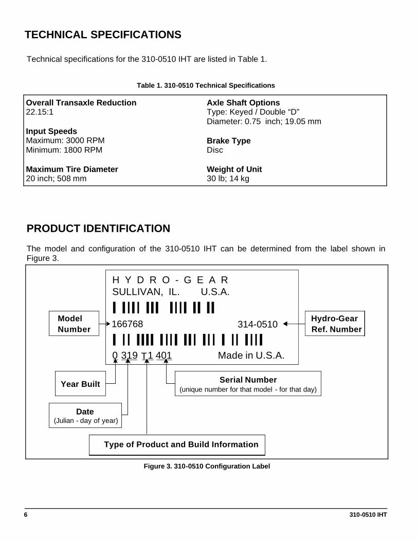
TECHNICAL SPECIFICATIONS
Overall Transaxle Reduction 22.15:1 Input Speeds Maximum: 3000 RPM Minimum: 1800 RPM Maximum Tire Diameter 20 inch; 508 mm
Axle Shaft Options Type: Keyed / Double “D” Diameter: 0.75 inch; 19.05 mm Brake Type Disc Weight of Unit 30 lb; 14 kg
Technical specifications for the 310-0510 IHT are listed in Table 1.
Table 1. 310-0510 Technical Specifications
PRODUCT IDENTIFICATION
The model and configuration of the 310-0510 IHT can be determined from the label shown in Figure 3.
Figure 3. 310-0510 Configuration Label
H Y D R O - G E A RSULLIVAN, IL. U.S.A.
I IIII III IIII II II13054 318-2400
I II IIII IIII III III I II IIII0 319 Z1 401 Made in U.S.A.
Year Built
Date(Julian - day of year)
Type of Product and Build Information
Serial Number(unique number for that model - for that day)
ModelNumber
Hydro-GearRef. Number
H Y D R O - G E A RSULLIVAN, IL. U.S.A.
I IIII III IIII II II13054 318-2400
I II IIII IIII III III I II IIII0 319 Z1 401 Made in U.S.A.
Year Built
Date(Julian - day of year)
Type of Product and Build Information
Serial Number(unique number for that model - for that day)
ModelNumber
Hydro-GearRef. Number314-0510 166768
T
310-0510 IHT 7
SECTION 2. SAFETY
This symbol points out important safety instructions which, if not followed, could endanger the personal safety and/or property of yourself and others. Read and follow all instructions in this manual before attempting maintenance on your transaxle. When you see this symbol - HEED ITS WARNING.
WARNING
POTENTIAL FOR SERIOUS INJURY
Inattention to proper safety, operation, or maintenance procedures could result in per-sonal injury, or damage to the equipment. Before servicing or repairing the 310-0510 IHT, fully read and understand the safety precautions described in this section.
PERSONAL SAFETY Certain safety precautions must be observed while servicing or repairing the 310-0510 IHT. This section addresses some of these precautions but must not be considered an all-inclusive source on safety information. This section is to be used in conjunction with all other safety material which may apply, such as:
1) Other manuals pertaining to this machine, 2) Local and shop safety rules and codes, 3) Governmental safety laws and regulations.
Be sure that you know and understand the equipment and the hazards associated with it. Do not place speed above safety.
Notify your supervisor whenever you feel there is any hazard involving the equipment or the performance of your job.
Never allow untrained or unauthorized person-nel to service or repair the equipment.
Wear appropriate clothing. Loose or hanging clothing or jewelry can be hazardous. Use the appropriate safety equipment, such as eye and hearing protection, and safety-toe and slip-proof shoes.
Never use compressed air to clean debris from yourself or your clothing.
TOOL SAFETY Use the proper tools and equipment for the task.
Inspect each tool before use and replace any tool that may be damaged or defective.
WORK AREA SAFETY Keep the work area neat and orderly. Be sure it is well lit, that extra tools are put away, trash and refuse are in the proper containers, and dirt or debris have been removed from the working areas of the machine.
The floor should be clean and dry, and all ex-tension cords or similar trip hazards should be removed.
SERVICING SAFETY Certain procedures may require the vehicle to be disabled in order to prevent possible injury to the servicing technician and/or bystanders.
The loss of hydrostatic drive line power may re-sult in the loss of hydrostatic braking capability. Proper brake maintenance is very important should this condition develop.
Some cleaning solvents are flammable. Use only approved cleaning materials. Do not use explosive or flammable liquids to clean the equipment.
To avoid possible fire do not use cleaning sol-vents in an area where a source of ignition may be present.
Discard used cleaning material in the appropri-ate containers.
310-0510 IHT 8
UNIT OPERATING HOT
SECTION 3. TROUBLESHOOTING
WARNING
Do not attempt any servicing or adjust-ments with the engine running. Use extreme caution while inspecting the drive belt assembly, and all vehicle link-age!
Follow all safety procedures outlined in the vehicle owner’s manual!
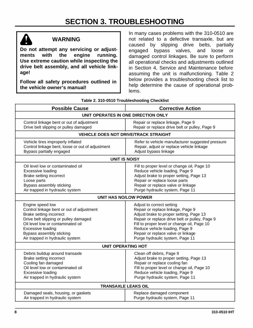
In many cases problems with the 310-0510 are not related to a defective transaxle, but are caused by slipping drive belts, partially engaged bypass valves, and loose or damaged control linkages. Be sure to perform all operational checks and adjustments outlined in Section 4, Service and Maintenance before assuming the unit is malfunctioning. Table 2 below provides a troubleshooting check list to help determine the cause of operational prob-lems.
Table 2. 310-0510 Troubleshooting Checklist
Vehicle tires improperly inflated Control linkage bent, loose or out of adjustment Bypass partially engaged
Refer to vehicle manufacturer suggested pressure Repair, adjust or replace vehicle linkage Adjust bypass linkage
UNIT IS NOISY
UNIT HAS NO/LOW POWER
Oil level low or contaminated oil Excessive loading Brake setting incorrect Loose parts Bypass assembly sticking Air trapped in hydraulic system
Debris buildup around transaxle Brake setting incorrect Cooling fan damaged Oil level low or contaminated oil Excessive loading Air trapped in hydraulic system
Clean off debris, Page 9 Adjust brake to proper setting, Page 13 Repair or replace cooling fan Fill to proper level or change oil, Page 10 Reduce vehicle loading, Page 9 Purge hydraulic system, Page 11
Corrective Action Possible Cause
VEHICLE DOES NOT DRIVE/TRACK STRAIGHT
Repair or replace linkage, Page 9 Repair or replace drive belt or pulley, Page 9
Control linkage bent or out of adjustment Drive belt slipping or pulley damaged
UNIT OPERATES IN ONE DIRECTION ONLY
Fill to proper level or change oil, Page 10 Reduce vehicle loading, Page 9 Adjust brake to proper setting, Page 13 Repair or replace loose parts Repair or replace valve or linkage Purge hydraulic system, Page 11
Adjust to correct setting Repair or replace linkage, Page 9 Adjust brake to proper setting, Page 13 Repair or replace drive belt or pulley, Page 9 Fill to proper level or change oil, Page 10 Reduce vehicle loading, Page 9 Repair or replace valve or linkage Purge hydraulic system, Page 11
Engine speed low Control linkage bent or out of adjustment Brake setting incorrect Drive belt slipping or pulley damaged Oil level low or contaminated oil Excessive loading Bypass assembly sticking Air trapped in hydraulic system
TRANSAXLE LEAKS OIL
Replace damaged component Purge hydraulic system, Page 11
Damaged seals, housing, or gaskets Air trapped in hydraulic system
310-0510 IHT 9
SECTION 4. SERVICE AND MAINTENANCE NOTE: Any servicing dealer attempting a warranty repair must have prior approval before conducting maintenance of a Hydro-Gear product unless the servicing dealer is a current Authorized Hydro-Gear Service Center.
EXTERNAL MAINTENANCE Regular external maintenance of the 310-0510 IHT should include the following:
1. Check the vehicle operator’s manual for the recommended load ratings. Insure the current application does not exceed load rating.
2. Check oil level in accordance with Figure 4 Page 10.
3. Inspect the vehicle drive belt, idler pulley(s), and idler spring(s). Insure that no belt slippage can occur. Slippage can cause low input speed to the transmission.
4. Inspect the transmission cooling fan for broken or distorted blades and remove any obstructions (grass clippings, leaves, dirt, etc.).
5. Inspect the axle parking brake and vehicle linkage to insure proper actuation and adjustment of the parking brake.
6. Inspect the vehicle control linkage to the directional control arm on transaxle. Also, insure the control arm is securely fastened to the trunnion arm of the transaxle.
7. Inspect the bypass mechanism on the transaxle and vehicle linkage to insure it actuates and releases fully.
SERVICE AND MAINTENANCE PROCEDURES
All the service and maintenance procedures presented on the following pages can be performed while the 310-0510 is mounted on the vehicle. Any repair procedures as
mentioned in the repair section of this manual must be performed after the unit has been removed from the vehicle.
FLUIDS
The fluids used in Hydro-Gear products have been carefully selected, and only equivalent, or better products should be substituted.
Typically, an engine oil with a minimum rating of 55 SUS at 212°F (100° C) and an API classi-fication of SL is recommended. A 20W-50 en-gine oil has been selected for use by the fac-tory and is recommended for normal operating temperatures.
FLUID VOLUME AND LEVEL
Fluid volume information is provided in Table 3.
Certain situations may require additional fluid to be added or even replaced. Refer to Page 4 and Figure 4 for the proper fill port location. Fill the 310-0510 to the top of the oil fill port. Recheck the fluid level once the unit has been operated for approximately 1 minute. Purging may be required. Refer to the purging procedures on page 11.
310-0510 IHT 10
FLUID CHANGE
FLUID CHANGE PROCEDURE
This transaxle is factory filled, sealed and does not require oil maintenance. However, in the event of oil contamination or degradation, oil addition or change may alleviate certain per-formance problems.
1. Remove the transaxle from the vehicle.
2. Clean the expansion tank and oil fill port areas of any debris.
3. Remove the oil fill port fitting.
4. Position the transaxle so the oil will drain completely out of the housing.
5. After all the oil is drained from the transaxle, remove the expansion tank by removing the self tapping bolt (10-32 x ½) that holds the tank support bracket.
6. Remove the tank and drain the oil from the tank. DO NOT remove the vent cap from the tank. DO NOT remove the tank hose or o-ring unless a replacement is needed.
7. Install the tank by first inserting the hose into the opening in the expansion tank. Push the tank opening over the o-ring to en-sure a proper seal.
8. Install the tank support bracket and self tap-ping bolt making sure not to cross thread the bolt. Torque the bolt to the lower value of the torque specification listed in Table 5.
9. Fill the transaxle at the oil fill port according to Figure 4.
10. Install the oil fill port fitting.
EXPANSION TANK FUNCTION
The expansion tank allows the 310-0510 to operate free of air entrainment and provides maximum lubrication to the mechanical and hydraulic components in the transaxle.
As the 310-0510 transaxle is operated, oil in the transaxle housing heats up which causes the oil to expand. The oil flows through an internal hose to the bottom of the vented expansion tank. As the oil cools, the oil in the transaxle housing contracts, causing the oil level to go down in the housing. This creates a negative pressure in the housing causing the oil to be drawn back into the case. This keeps the transaxle housing full of oil at specified operating temperatures.
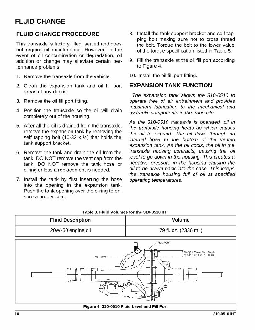
Fluid Description Volume
20W-50 engine oil 79 fl. oz. (2336 ml.)
Table 3. Fluid Volumes for the 310-0510 IHT
Figure 4. 310-0510 Fluid Level and Fill Port
FILL PORT
OIL LEVEL
1¼" (31.75mm) Max. Depth at 50°- 100° F (10°- 38° C)
310-0510 IHT 11
PURGING PROCEDURES
Due to the effects air has on efficiency in hydrostatic drive applications, it is critical that it be purged from the system. These purge procedures should be imple-mented any time a hydrostatic system has been opened to facilitate maintenance or any additional oil has been added to the system. Air creates inefficiency because its compres-sion and expansion rate is higher than that of the oil approved for use in hydrostatic drive systems. The resulting symptoms in hydrostatic systems may be: 1. Noisy operation. 2. Lack of power or drive after short term
operation. 3. High operation temperature and excessive expansion of oil. Before starting, make sure the transaxle/transmission is at the proper oil level. If it is not, fill to the specifications outlined on page 10, Figure 4.
The following procedures should be performed with the vehicle drive wheels off the ground, then repeated under normal operating condi-tions.
1. With the bypass valve open and the engine running, slowly move the directional control in both forward and reverse directions (5 to 6 times), as air is purged from the unit, the oil level will drop.
2. With the bypass valve closed and the engine running, slowly move the directional control in both forward and reverse directions (5 to 6 times). Check the oil level, and add oil as required after stopping engine.
3. It may be necessary to repeat Steps 1 and 2 until all the air is completely purged from the system. When the transaxle moves forward and reverse at normal speed purging is complete.
310-0510 IHT 12
RETURN TO NEUTRAL SETTING (FOOT CONTROL)
The return to neutral mechanism on the trans-mission is designed to set the directional con-trol into a neutral position when the operator re-moves their foot from the foot control. Follow the procedures below to properly adjust the re-turn to neutral mechanism on the transaxle:
1. Confirm the transaxle is in the operat-ing mode (bypass disengaged). Raise the vehicle’s drive tires off the ground to allow free rotation.
NOTE: It may be necessary to remove the drive tire from the axle hub to access the linkage control and the transaxle return arm.
2. Remove the Original Equipment Manufac-turer’s (OEM’s) control linkage at the control arm. Refer to Figure 5.
3. Start the engine and increase the throttle to full engine speed.
4. Check for axle rotation. If the axles do not rotate, go to Step 5. If the axles rotate, go to Step 6.
5. Stop the vehicle’s engine. Reattach and ad-just the OEM linkage according to the OEM manual. Recheck according to Step 3 and 4. Stop the vehicle engine. Refer to Figure 5.
6. Note the axle directional movement. Stop the vehicle engine. Loosen the adjusting puck screw until the puck can be rotated. Rotate the adjusting puck the opposite di-rection of the wheel rotation in 5 degree in-crements. Tighten the adjusting puck screw. Refer to Table 5. Required Torque Values, Page 15. Recheck according to steps 3 and 4. Stop the vehicle engine. Reattach and adjust the OEM linkage according to the OEM manual. Recheck according to steps 3 and 4. Refer to Figure 5.
WARNING
POTENTIAL FOR SERIOUS INJURY
Certain procedures require the vehicle engine to be operated and the vehicle to be raised off the ground. To prevent possible injury to the servicing techni-cian and/or bystanders, insure the vehicle is properly secured.
WARNING
Do not attempt any adjustments with the engine running. Use extreme caution while inspecting all vehicle linkage! Follow all safety procedures outlined in the vehicle owner’s manual.
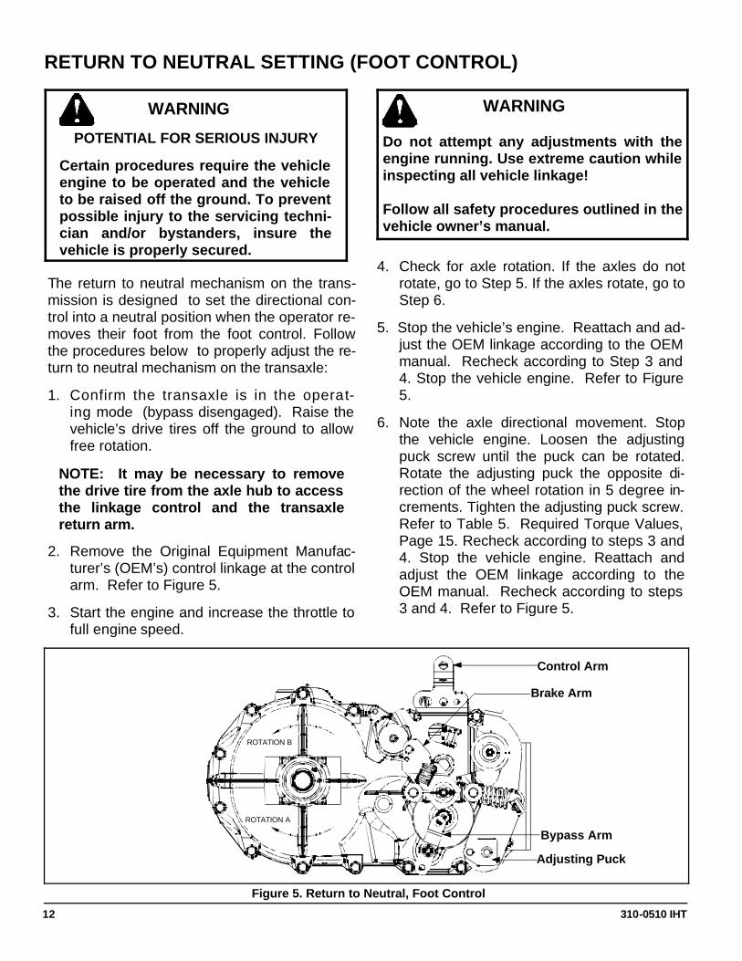
Figure 5. Return to Neutral, Foot Control
Control Arm
Bypass Arm
ROTATION B
ROTATION A
Brake Arm
Adjusting Puck
310-0510 IHT 13
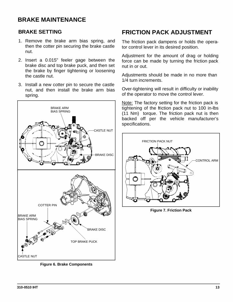
BRAKE SETTING
1. Remove the brake arm bias spring, and then the cotter pin securing the brake castle nut.
2. Insert a 0.015" feeler gage between the brake disc and top brake puck, and then set the brake by finger tightening or loosening the castle nut.
3. Install a new cotter pin to secure the castle nut, and then install the brake arm bias spring.
FRICTION PACK ADJUSTMENT The friction pack dampens or holds the opera-tor control lever in its desired position.
Adjustment for the amount of drag or holding force can be made by turning the friction pack nut in or out.
Adjustments should be made in no more than 1/4 turn increments.
Over-tightening will result in difficulty or inability of the operator to move the control lever.
Note: The factory setting for the friction pack is tightening of the friction pack nut to 100 in-lbs (11 Nm) torque. The friction pack nut is then backed off per the vehicle manufacturer’s specifications.
BRAKE MAINTENANCE
Figure 6. Brake Components
Figure 7. Friction Pack
CONTROL ARM
FRICTION PACK NUT
BRAKE ARM BIAS SPRING
CASTLE NUT
BRAKE DISC
BRAKE DISC
CASTLE NUT
BRAKE ARM BIAS SPRING
COTTER PIN
TOP BRAKE PUCK
310-0510 IHT 14
SECTION 5. REPAIR HOW TO USE THIS SECTION
Each subassembly illustrated in this section is illustrated by an exploded view showing the parts involved. The item reference numbers in each illustration are for assembly instructions only. See pages 31 and 33 for part names and descriptions. A complete ex-ploded view and item list of the transaxle is pro-vided at the end of this section.
Many of the parts and subassemblies of this transaxle can be removed and serviced inde-pendently of other components. Where some components and assemblies must be removed before a given assembly can be serviced, that information is given at the beginning of the disassembly instructions.
GENERAL INSTRUCTIONS
Cleanliness is a primary means of assuring satisfactory life on repaired units. Thoroughly clean all exposed surfaces prior to any type of maintenance. Cleaning of all parts by using a solvent wash and air drying is usually adequate. As with any precision equipment, all parts must be kept free of foreign material and chemicals.
Protect all exposed sealing surfaces and open cavities from damage and foreign material. The external surfaces should be cleaned before beginning any repairs.
Upon removal, it is recommended that all seals, O-rings, and gaskets be replaced. During installation lightly lubricate all seals, O-rings, gaskets with a clean petroleum jelly prior to assembly. Also protect the inner diameter of seals by covering the shaft with a cellophane (plastic wrap, etc.) material.
Parts requiring replacement must be replaced from the appropriate kits identified in the Items Listing, found at the end of this manual. Use only original Hydro-Gear replacement parts found listed in BLN-50937 (microfiche) or BLN-51427 (CD).
IMPORTANT: When internal repair is per-formed on the 310-0510 IHT, the filter assem-bly must be replaced.
TRANSAXLE REMOVAL
It is necessary to remove the 310-0510 from the vehicle before performing the repair procedures presented in this section.
LIMITED DISASSEMBLY
The following procedures are presented in the order in which they must be performed to completely disassemble the unit. Do not disassemble the unit any farther than is necessary to accomplish the required repairs. Each disassembly procedure is followed by a corresponding assembly procedure.
Reassembly is accomplished by performing the “Assembly” portions of the procedures. If the unit has been completely disassembled, a sum-mary of the assembly procedures, in the order in which they should occur, is given on page 27.
310-0510 IHT 15
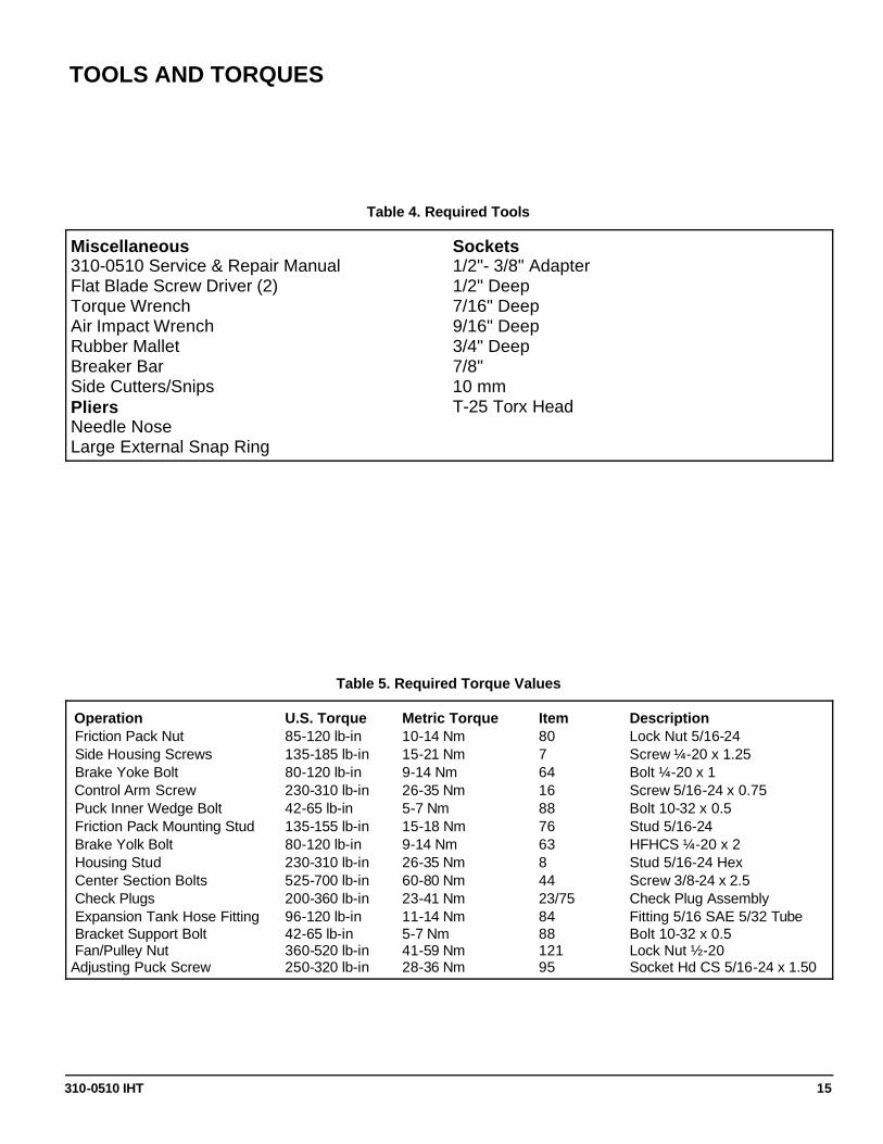
Operation U.S. Torque Metric Torque Item Description Friction Pack Nut 85-120 lb-in 10-14 Nm 80 Lock Nut 5/16-24 Side Housing Screws 135-185 lb-in 15-21 Nm 7 Screw ¼-20 x 1.25 Brake Yoke Bolt 80-120 lb-in 9-14 Nm 64 Bolt ¼-20 x 1 Control Arm Screw 230-310 lb-in 26-35 Nm 16 Screw 5/16-24 x 0.75 Puck Inner Wedge Bolt 42-65 lb-in 5-7 Nm 88 Bolt 10-32 x 0.5 Friction Pack Mounting Stud 135-155 lb-in 15-18 Nm 76 Stud 5/16-24 Brake Yolk Bolt 80-120 lb-in 9-14 Nm 63 HFHCS ¼-20 x 2 Housing Stud 230-310 lb-in 26-35 Nm 8 Stud 5/16-24 Hex Center Section Bolts 525-700 lb-in 60-80 Nm 44 Screw 3/8-24 x 2.5 Check Plugs 200-360 lb-in 23-41 Nm 23/75 Check Plug Assembly Expansion Tank Hose Fitting 96-120 lb-in 11-14 Nm 84 Fitting 5/16 SAE 5/32 Tube Bracket Support Bolt 42-65 lb-in 5-7 Nm 88 Bolt 10-32 x 0.5 Fan/Pulley Nut 360-520 lb-in 41-59 Nm 121 Lock Nut ½-20 Adjusting Puck Screw 250-320 lb-in 28-36 Nm 95 Socket Hd CS 5/16-24 x 1.50
Table 5. Required Torque Values
Miscellaneous 310-0510 Service & Repair Manual Flat Blade Screw Driver (2) Torque Wrench Air Impact Wrench Rubber Mallet Breaker Bar Side Cutters/Snips Pliers Needle Nose Large External Snap Ring
Sockets 1/2"- 3/8" Adapter 1/2" Deep 7/16" Deep 9/16" Deep 3/4" Deep 7/8" 10 mm T-25 Torx Head
Table 4. Required Tools
TOOLS AND TORQUES
310-0510 IHT 16
2
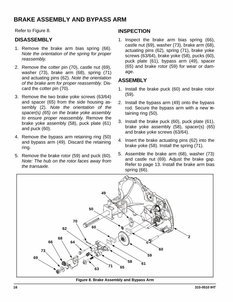
BRAKE ASSEMBLY AND BYPASS ARM
Refer to Figure 8.
DISASSEMBLY
1. Remove the brake arm bias spring (66). Note the orientation of the spring for proper reassembly.
2. Remove the cotter pin (70), castle nut (69), washer (73), brake arm (68), spring (71) and actuating pins (62). Note the orientation of the brake arm for proper reassembly. Dis-card the cotter pin (70).
3. Remove the two brake yoke screws (63/64) and spacer (65) from the side housing as-sembly (2). Note the orientation of the spacer(s) (65) on the brake yoke assembly to ensure proper reassembly. Remove the brake yoke assembly (58), puck plate (61) and puck (60).
4. Remove the bypass arm retaining ring (50) and bypass arm (49). Discard the retaining ring.
5. Remove the brake rotor (59) and puck (60). Note: The hub on the rotor faces away from the transaxle.
INSPECTION
1. Inspect the brake arm bias spring (66), castle nut (69), washer (73), brake arm (68), actuating pins (62), spring (71), brake yoke screws (63/64), brake yoke (58), pucks (60), puck plate (61), bypass arm (49), spacer (65) and brake rotor (59) for wear or dam-age.
ASSEMBLY
1. Install the brake puck (60) and brake rotor (59).
2. Install the bypass arm (49) onto the bypass rod. Secure the bypass arm with a new re-taining ring (50).
3. Install the brake puck (60), puck plate (61), brake yoke assembly (58), spacer(s) (65) and brake yoke screws (63/64).
4. Insert the brake actuating pins (62) into the brake yoke (58). Install the spring (71).
5. Assemble the brake arm (68), washer (73) and castle nut (69). Adjust the brake gap. Refer to page 13. Install the brake arm bias spring (66).
73
69
Figure 8. Brake Assembly and Bypass Arm
66 68
63 71
64
62
65
70
58 61
60
59
60
50
49
310-0510 IHT 17
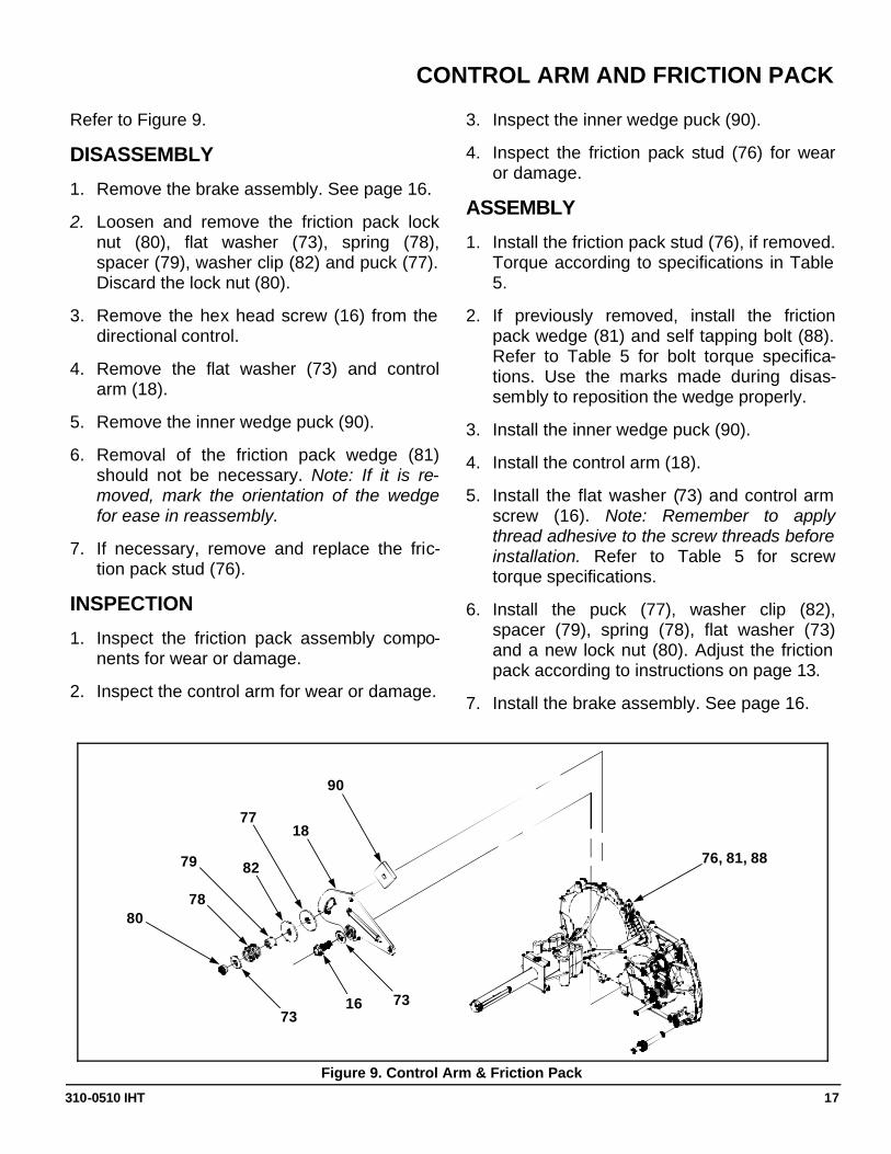
CONTROL ARM AND FRICTION PACK
Refer to Figure 9.
DISASSEMBLY
1. Remove the brake assembly. See page 16.
2. Loosen and remove the friction pack lock nut (80), flat washer (73), spring (78), spacer (79), washer clip (82) and puck (77). Discard the lock nut (80).
3. Remove the hex head screw (16) from the directional control.
4. Remove the flat washer (73) and control arm (18).
5. Remove the inner wedge puck (90).
6. Removal of the friction pack wedge (81) should not be necessary. Note: If it is re-moved, mark the orientation of the wedge for ease in reassembly.
7. If necessary, remove and replace the fric-tion pack stud (76).
INSPECTION
1. Inspect the friction pack assembly compo-nents for wear or damage.
2. Inspect the control arm for wear or damage.
3. Inspect the inner wedge puck (90).
4. Inspect the friction pack stud (76) for wear or damage.
ASSEMBLY
1. Install the friction pack stud (76), if removed. Torque according to specifications in Table 5.
2. If previously removed, install the friction pack wedge (81) and self tapping bolt (88). Refer to Table 5 for bolt torque specifica-tions. Use the marks made during disas-sembly to reposition the wedge properly.
3. Install the inner wedge puck (90).
4. Install the control arm (18).
5. Install the flat washer (73) and control arm screw (16). Note: Remember to apply thread adhesive to the screw threads before installation. Refer to Table 5 for screw torque specifications.
6. Install the puck (77), washer clip (82), spacer (79), spring (78), flat washer (73) and a new lock nut (80). Adjust the friction pack according to instructions on page 13.
7. Install the brake assembly. See page 16.
Figure 9. Control Arm & Friction Pack
73
78 80
79 82
77
16 73
18
90
76, 81, 88
310-0510 IHT 18
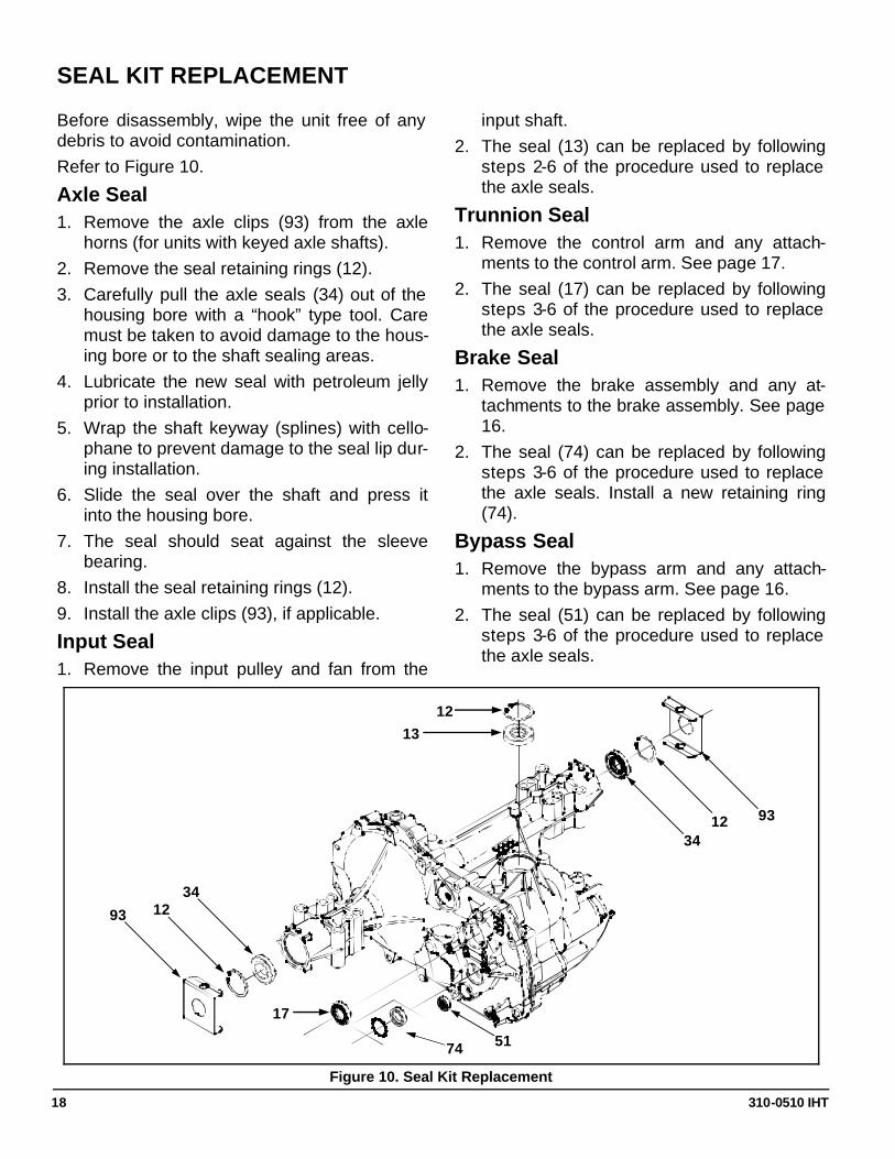
Figure 10. Seal Kit Replacement
SEAL KIT REPLACEMENT
Before disassembly, wipe the unit free of any debris to avoid contamination. Refer to Figure 10.
Axle Seal 1. Remove the axle clips (93) from the axle
horns (for units with keyed axle shafts). 2. Remove the seal retaining rings (12). 3. Carefully pull the axle seals (34) out of the
housing bore with a “hook” type tool. Care must be taken to avoid damage to the hous-ing bore or to the shaft sealing areas.
4. Lubricate the new seal with petroleum jelly prior to installation.
5. Wrap the shaft keyway (splines) with cello-phane to prevent damage to the seal lip dur-ing installation.
6. Slide the seal over the shaft and press it into the housing bore.
7. The seal should seat against the sleeve bearing.
8. Install the seal retaining rings (12). 9. Install the axle clips (93), if applicable.
Input Seal 1. Remove the input pulley and fan from the
input shaft. 2. The seal (13) can be replaced by following
steps 2-6 of the procedure used to replace the axle seals.
Trunnion Seal 1. Remove the control arm and any attach-
ments to the control arm. See page 17. 2. The seal (17) can be replaced by following
steps 3-6 of the procedure used to replace the axle seals.
Brake Seal 1. Remove the brake assembly and any at-
tachments to the brake assembly. See page 16.
2. The seal (74) can be replaced by following steps 3-6 of the procedure used to replace the axle seals. Install a new retaining ring (74).
Bypass Seal 1. Remove the bypass arm and any attach-
ments to the bypass arm. See page 16. 2. The seal (51) can be replaced by following
steps 3-6 of the procedure used to replace the axle seals.
34
13
93 12
51 74
17
34
93 12
12
310-0510 IHT 19
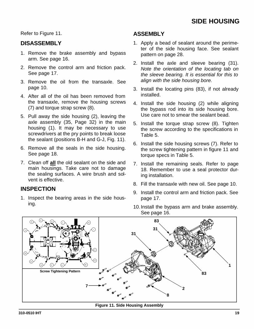
SIDE HOUSING
Refer to Figure 11.
DISASSEMBLY
1. Remove the brake assembly and bypass arm. See page 16.
2. Remove the control arm and friction pack. See page 17.
3. Remove the oil from the transaxle. See page 10.
4. After all of the oil has been removed from the transaxle, remove the housing screws (7) and torque strap screw (8).
5. Pull away the side housing (2), leaving the axle assembly (35, Page 32) in the main housing (1). It may be necessary to use screwdrivers at the pry points to break loose the sealant (positions B-H and G-J, Fig. 11).
6. Remove all the seals in the side housing. See page 18.
7. Clean off all the old sealant on the side and main housings. Take care not to damage the sealing surfaces. A wire brush and sol-vent is effective.
INSPECTION
1. Inspect the bearing areas in the side hous-ing.
ASSEMBLY
1. Apply a bead of sealant around the perime-ter of the side housing face. See sealant pattern on page 28.
2. Install the axle and sleeve bearing (31). Note the orientation of the locating tab on the sleeve bearing. It is essential for this to align with the side housing bore.
3. Install the locating pins (83), if not already installed.
4. Install the side housing (2) while aligning the bypass rod into its side housing bore. Use care not to smear the sealant bead.
5. Install the torque strap screw (8). Tighten the screw according to the specifications in Table 5.
6. Install the side housing screws (7). Refer to the screw tightening pattern in figure 11 and torque specs in Table 5.
7. Install the remaining seals. Refer to page 18. Remember to use a seal protector dur-ing installation.
8. Fill the transaxle with new oil. See page 10.
9. Install the control arm and friction pack. See page 17.
10. Install the bypass arm and brake assembly. See page 16.
Figure 11. Side Housing Assembly
1
83
2
83
31 31
8
7
B
H
D F K
J
G C
E L N
I
A
O
M
Screw Tightening Pattern
310-0510 IHT 20
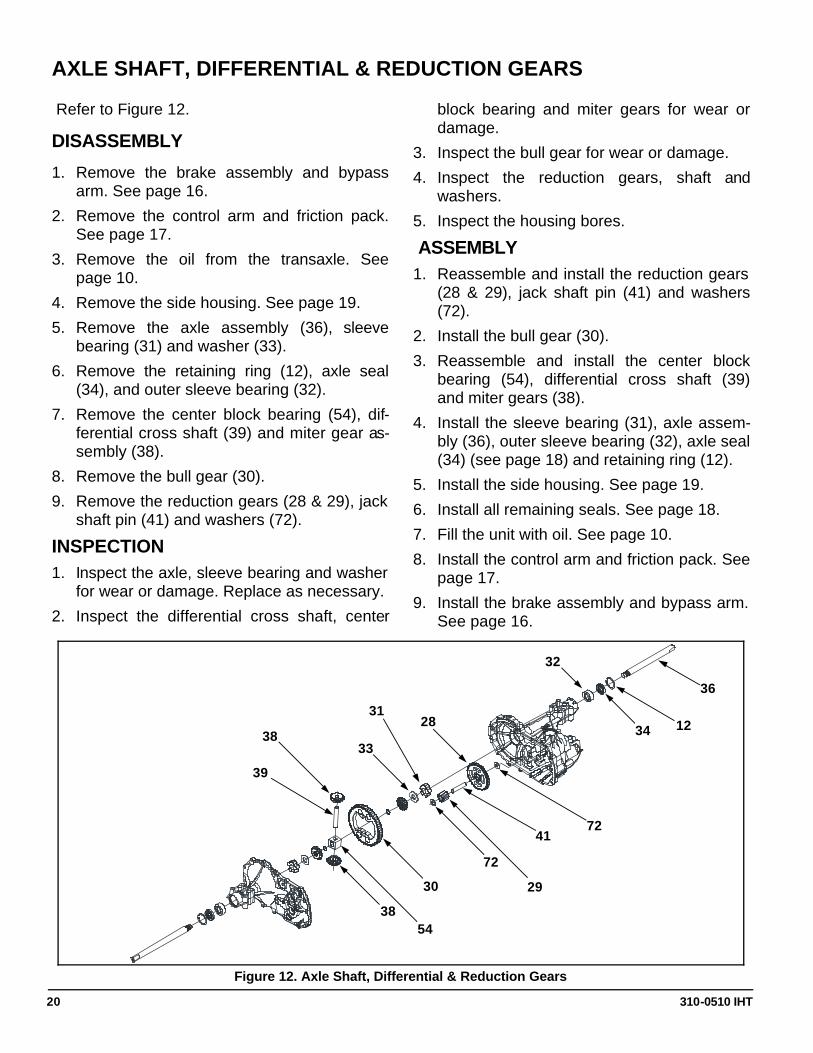
36
AXLE SHAFT, DIFFERENTIAL & REDUCTION GEARS
Refer to Figure 12.
DISASSEMBLY
1. Remove the brake assembly and bypass arm. See page 16.
2. Remove the control arm and friction pack. See page 17.
3. Remove the oil from the transaxle. See page 10.
4. Remove the side housing. See page 19.
5. Remove the axle assembly (36), sleeve bearing (31) and washer (33).
6. Remove the retaining ring (12), axle seal (34), and outer sleeve bearing (32).
7. Remove the center block bearing (54), dif-ferential cross shaft (39) and miter gear as-sembly (38).
8. Remove the bull gear (30).
9. Remove the reduction gears (28 & 29), jack shaft pin (41) and washers (72).
INSPECTION 1. Inspect the axle, sleeve bearing and washer
for wear or damage. Replace as necessary.
2. Inspect the differential cross shaft, center
block bearing and miter gears for wear or damage.
3. Inspect the bull gear for wear or damage.
4. Inspect the reduction gears, shaft and washers.
5. Inspect the housing bores.
ASSEMBLY
1. Reassemble and install the reduction gears (28 & 29), jack shaft pin (41) and washers (72).
2. Install the bull gear (30).
3. Reassemble and install the center block bearing (54), differential cross shaft (39) and miter gears (38).
4. Install the sleeve bearing (31), axle assem-bly (36), outer sleeve bearing (32), axle seal (34) (see page 18) and retaining ring (12).
5. Install the side housing. See page 19.
6. Install all remaining seals. See page 18.
7. Fill the unit with oil. See page 10.
8. Install the control arm and friction pack. See page 17.
9. Install the brake assembly and bypass arm. See page 16.
Figure 12. Axle Shaft, Differential & Reduction Gears
12
54
28
72
33
39
38
38
30
31
72
29
41
32
34
310-0510 IHT 21
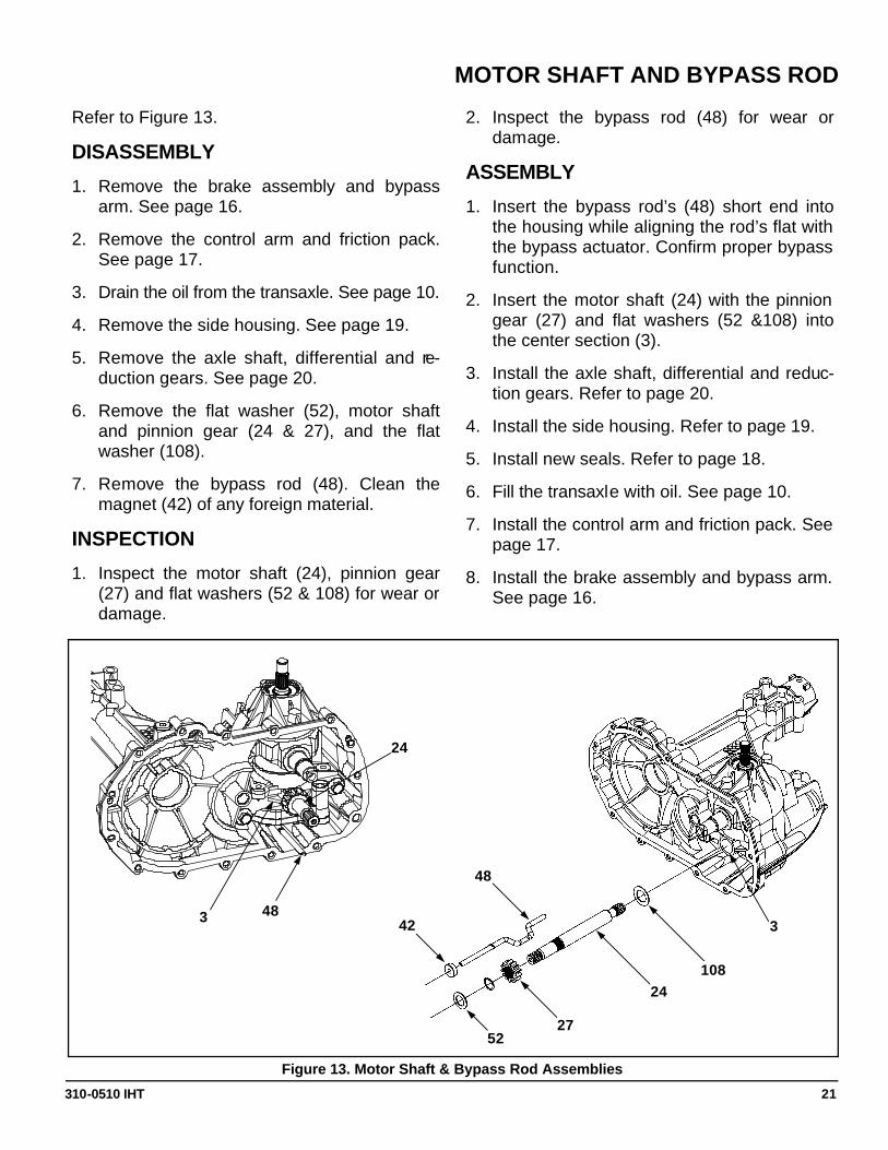
MOTOR SHAFT AND BYPASS ROD
Refer to Figure 13.
DISASSEMBLY
1. Remove the brake assembly and bypass arm. See page 16.
2. Remove the control arm and friction pack. See page 17.
3. Drain the oil from the transaxle. See page 10.
4. Remove the side housing. See page 19.
5. Remove the axle shaft, differential and re-duction gears. See page 20.
6. Remove the flat washer (52), motor shaft and pinnion gear (24 & 27), and the flat washer (108).
7. Remove the bypass rod (48). Clean the magnet (42) of any foreign material.
INSPECTION
1. Inspect the motor shaft (24), pinnion gear (27) and flat washers (52 & 108) for wear or damage.
2. Inspect the bypass rod (48) for wear or damage.
ASSEMBLY
1. Insert the bypass rod’s (48) short end into the housing while aligning the rod’s flat with the bypass actuator. Confirm proper bypass function.
2. Insert the motor shaft (24) with the pinnion gear (27) and flat washers (52 &108) into the center section (3).
3. Install the axle shaft, differential and reduc-tion gears. Refer to page 20.
4. Install the side housing. Refer to page 19.
5. Install new seals. Refer to page 18.
6. Fill the transaxle with oil. See page 10.
7. Install the control arm and friction pack. See page 17.
8. Install the brake assembly and bypass arm. See page 16.
3
108
Figure 13. Motor Shaft & Bypass Rod Assemblies
24
27 52
42
48
48 3
24
310-0510 IHT 22
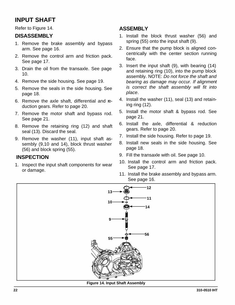
INPUT SHAFT
Figure 14. Input Shaft Assembly
12
Refer to Figure 14.
DISASSEMBLY
1. Remove the brake assembly and bypass arm. See page 16.
2. Remove the control arm and friction pack. See page 17.
3. Drain the oil from the transaxle. See page 10.
4. Remove the side housing. See page 19.
5. Remove the seals in the side housing. See page 18.
6. Remove the axle shaft, differential and re-duction gears. Refer to page 20.
7. Remove the motor shaft and bypass rod. See page 21.
8. Remove the retaining ring (12) and shaft seal (13). Discard the seal.
9. Remove the washer (11), input shaft as-sembly (9,10 and 14), block thrust washer (56) and block spring (55).
INSPECTION
1. Inspect the input shaft components for wear or damage.
ASSEMBLY
1. Install the block thrust washer (56) and spring (55) onto the input shaft (9).
2. Ensure that the pump block is aligned con-centrically with the center section running face.
3. Insert the input shaft (9), with bearing (14) and retaining ring (10), into the pump block assembly. NOTE: Do not force the shaft and bearing as damage may occur. If alignment is correct the shaft assembly will fit into place.
4. Install the washer (11), seal (13) and retain-ing ring (12).
5. Install the motor shaft & bypass rod. See page 21.
6. Install the axle, differential & reduction gears. Refer to page 20.
7. Install the side housing. Refer to page 19. 8. Install new seals in the side housing. See
page 18. 9. Fill the transaxle with oil. See page 10. 10. Install the control arm and friction pack.
See page 17. 11. Install the brake assembly and bypass arm.
See page 16.
11
14
55
13
10
9
56
310-0510 IHT 23
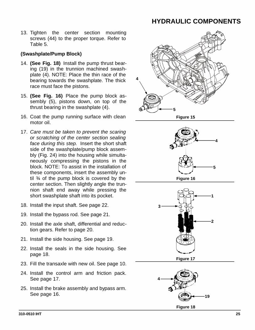
HYDRAULIC COMPONENTS Refer to Figures 15-24.
DISASSEMBLY
(Pump Block)
1. Remove the brake assembly and bypass arm. See page 16.
2. Remove the control arm and friction pack. See page 17.
3. Drain the oil from the transaxle. See page 10.
4. Remove the side housing. See page 19.
5. Remove the seals in the side housing. See page 18.
6. Remove the axle shaft, differential and re-duction gears. Refer to page 20.
7. Remove the motor shaft and bypass rod. See page 21.
8. Remove the input shaft. See page 22.
9. (See Fig. 15) Remove the swashplate (4) and pump cylinder block (5) as one assem-bly. NOTE: Removal will be aided by apply-ing a small amount of pressure on the trun-nion mounted swashplate towards the cen-ter section. Also note that the control arm (18, Page 32) may be loosely assembled at this point to assist in swashplate removal. While gently removing the swashplate and block assembly, keep the block face flush with the center section to minimize damage to the running surface.
10. (See Fig. 16) Disassemble the pump cylin-der block (5) from the swashplate (4).
11. (See Fig. 17) Check each piston for proper operation by pressing the pistons in and re-leasing them in the block bore. Disassem-ble the pump cylinder block. Check for pis-ton/block wear in the cylinder bore. Inspect the pistons (1), piston springs (2) and pis-ton seats (3) for excessive wear or dam-age. NOTE: Piston seats may be held in place in the piston by residual oil.
12. Reassemble the pistons, springs and seats into the cylinder block and set aside.
13. (See Fig. 18) Remove the thrust bearing assembly (19) from the swashplate (4).
(Center Section/Filter)
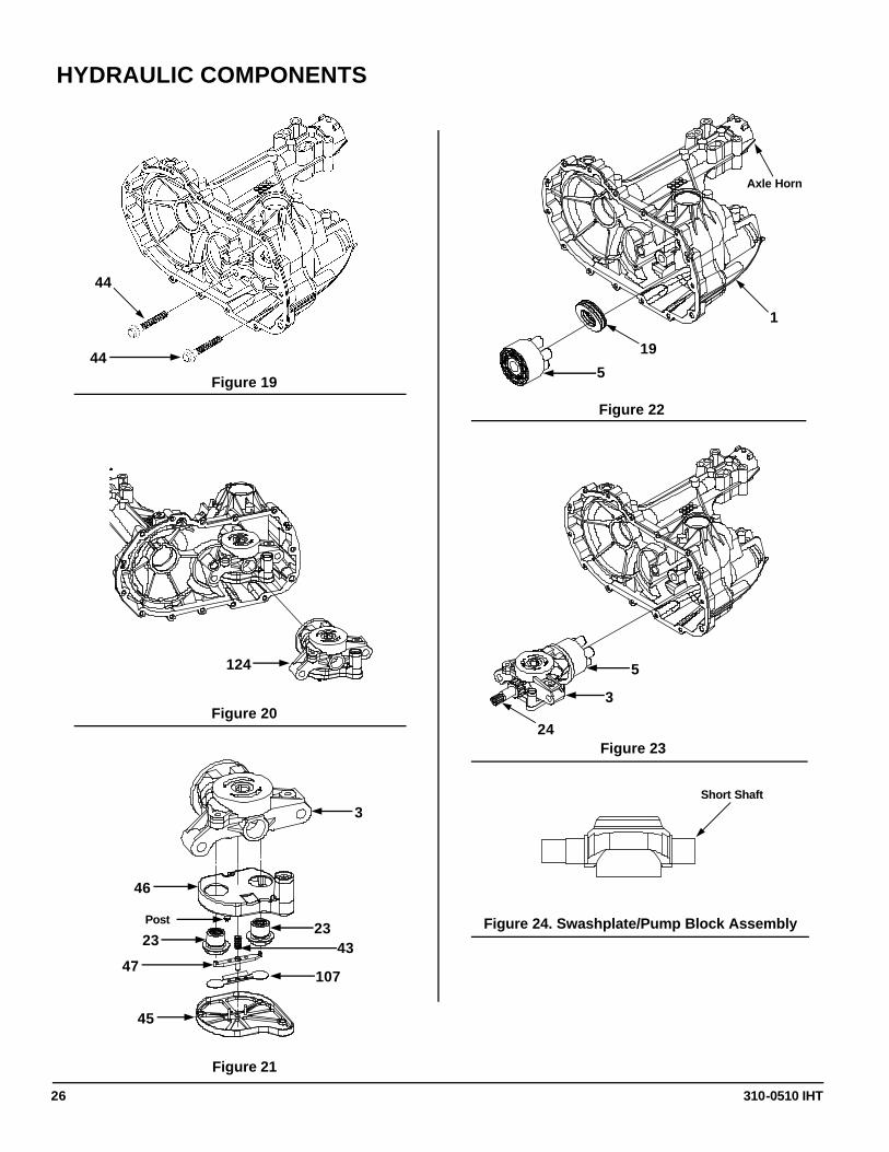
14. (See Fig. 19) Remove the center section mounting screws (44). NOTE: The center section is under motor block piston spring pressure. These screws are factory in-stalled to 700 in. lbs. (80 Nm) and use an anaerobic thread adhesive. A breaker bar will be required at this step. Clean the inter-nal threads of the mounting holes with compressed air.
15. Remove the center section and filter as-sembly (124, Fig. 20).
16. (See Fig. 21) Remove the filter (45) from the filter base (46) by snipping the four posts with side cutters or applicable tool. NOTE: This filter cannot be reused.
17. Remove and inspect the deflector (107), bypass actuator (47) and bypass spring (43).
18. Note the location of both check plugs (23) before removal for correct placement dur-ing reassembly. Remove and inspect the check plug assemblies (23) for debris or damage.
19. Remove the filter base (46) and discard it. NOTE: The filter base is included in the fil-ter kit to be installed during reassembly of the unit.
(Motor Block)
20. (See Fig. 22) Remove the motor cylinder block assembly (5) from the housing (1).
21. Disassemble the motor cylinder block as-sembly (5). Check each piston for proper operation by pressing the pistons in and re-leasing them in the block bore. Disassem-ble the motor cylinder block. Check for pis-ton/block wear in the cylinder bore. Inspect
310-0510 IHT 24
HYDRAULIC COMPONENTS
the pistons, piston springs and piston seats for excessive wear or damage. NOTE: Pis-ton seats may be held in place in the piston by residual oil.
22. Reassemble the pistons, springs and seats into the cylinder block and set aside.
23. Remove the thrust bearing assembly (19) from the housing (1). Inspect the thrust bearing and thrust bearing cavity in the housing.
INSPECTION
1. Inspect the pump cylinder block running surface for wear or damage.
2. Inspect the swashplate and thrust bearing assemblies for wear or damage.
3. Inspect the center section block running surfaces. NOTE: These “sealing” surfaces should be smooth in appearance without scratches, scoring, nicks or abrasions. Drag a fingernail across the surface to detect un-even wear or scratches which may not be visible.
4. Inspect the threaded check plug ports of the center section for debris or damage.
5. Inspect the motor cylinder block running surface for damage and wear.
6. Inspect all bearing, bushing and wear areas in the housing.
ASSEMBLY
(Motor Block)
1. (See Fig. 22) Turn the housing (1) so the axle horn is pointing down. This will assist in the installation of the thrust bearing assem-bly (19) keeping it in the bearing cavity dur-ing installation of the center section assem-bly.
2. Insert the thrust bearing (19) in the housing (1). NOTE: Place the thin race of the bear-ing towards the housing bearing cavity. The
thick race must face the pistons.
(Center Section)
3. (See Fig. 21) Install the new filter base (46) onto the center section (3).
4. Install the check plugs (23), in their correct location, into the center section (3). Tighten the check plugs according to Table 5.
5. Install the bypass spring (43) into the filter base (46).
6. Install the deflector (107) into the underside of the filter (45).
7. Install the bypass actuator (47) into the un-derside of the deflector (107).
8. Hold the stem of the bypass actuator (47) from the top of the filter (45) to retain the deflector (107) and bypass actuator (47) in place when snapping the filter (45) onto the filter base (46). NOTE: Filter installation is best accomplished by using the spacer (65, Page 32) as an assembly tool over each of the (4) snaps while lightly tapping with a rubber mallet. Excessive force will result in damage to the plastic filter components.
9. (See Figures 13 & 23) Install the motor shaft (24), pinion gear (27) and flat washers (52 & 108) into the center section (3).
10. Assemble the motor block assembly (5) onto the motor shaft (24).
11. (See Fig. 23) Install the motor shaft, center section and motor block assembly so that the block pistons contact the thrust bearing race. NOTE: Hold in place and insure all pistons are still positioned correctly in the cylinder bore by confirming spring bias against the center section.
12. (See Fig. 19) After applying thread adhe-sive, insert the center section mounting screws (44) while holding downward pres-sure on the center section assembly (3, Fig. 23).
310-0510 IHT 25
HYDRAULIC COMPONENTS
13. Tighten the center section mounting screws (44) to the proper torque. Refer to Table 5.
(Swashplate/Pump Block)
14. (See Fig. 18) Install the pump thrust bear-ing (19) in the trunnion machined swash-plate (4). NOTE: Place the thin race of the bearing towards the swashplate. The thick race must face the pistons.
15. (See Fig. 16) Place the pump block as-sembly (5), pistons down, on top of the thrust bearing in the swashplate (4).
16. Coat the pump running surface with clean motor oil.
17. Care must be taken to prevent the scaring or scratching of the center section sealing face during this step. Insert the short shaft side of the swashplate/pump block assem-bly (Fig. 24) into the housing while simulta-neously compressing the pistons in the block. NOTE: To assist in the installation of these components, insert the assembly un-til ¾ of the pump block is covered by the center section. Then slightly angle the trun-nion shaft end away while pressing the short swashplate shaft into its pocket.
18. Install the input shaft. See page 22.
19. Install the bypass rod. See page 21.
20. Install the axle shaft, differential and reduc-tion gears. Refer to page 20.
21. Install the side housing. See page 19.
22. Install the seals in the side housing. See page 18.
23. Fill the transaxle with new oil. See page 10.
24. Install the control arm and friction pack. See page 17.
25. Install the brake assembly and bypass arm. See page 16.
Figure 15
Figure 16
Figure 17
Figure 18
4
5
5
4
2
1
3
4
19
310-0510 IHT 26
3
46
HYDRAULIC COMPONENTS
Figure 21
Figure 19
44
44
Figure 20
124
Post
23 23
43 47
107
45
Figure 22
1
19
5
Axle Horn
Figure 23
5
3
24
Figure 24. Swashplate/Pump Block Assembly
Short Shaft
310-0510 IHT 27
TRANSAXLE INSTALLATION
Use the following procedure to complete the in-stallation of the transaxle on the vehicle.
1. Install and secure the transaxle on the vehicle according to the instructions in the vehicle owner’s manual.
2. With the vehicle raised, install the wheels on the axles, and snug the wheel hardware.
3. Lower the vehicle wheels to the ground and torque the wheel hardware per the vehicle owner’s manual.
ASSEMBLY AFTER A COMPLETE TEARDOWN
If the unit has been torn down completely, the following summary identifies the assembly pro-cedures necessary to completely assemble the unit. Each assembly procedure is located by a page reference.
The part reference numbers provided in each assembly procedure are keyed to the individual exploded views, and are also keyed to the complete unit exploded view on page 32.
1. Install the hydraulic components. See pages 23-26.
2. Install the input shaft. See page 22.
3. Install the bypass rod. See page 21.
4. Install the axle shaft, differential and reduc-tion gears. See page 20.
5. Install the side housing. See page 19.
6. Install new seals in the side housing. Refer to page 18.
7. Fill the transaxle with new oil. See page 10.
8. Install the control arm and friction pack. See page 17.
9. Install the brake assembly and bypass arm. See page 16.
10. Install the transaxle onto the vehicle.
11. Perform the purge procedures listed on page 11.
12. Perform the return to neutral procedure on page 12.
310-0510 IHT 28
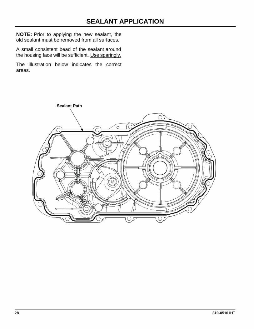
SEALANT APPLICATION
NOTE: Prior to applying the new sealant, the old sealant must be removed from all surfaces.
A small consistent bead of the sealant around the housing face will be sufficient. Use sparingly.
The illustration below indicates the correct areas.
Sealant Path
310-0510 IHT 29
310-0710 INTEGRATED HYDROSTATIC TRANSAXLE
DESCRIPTION
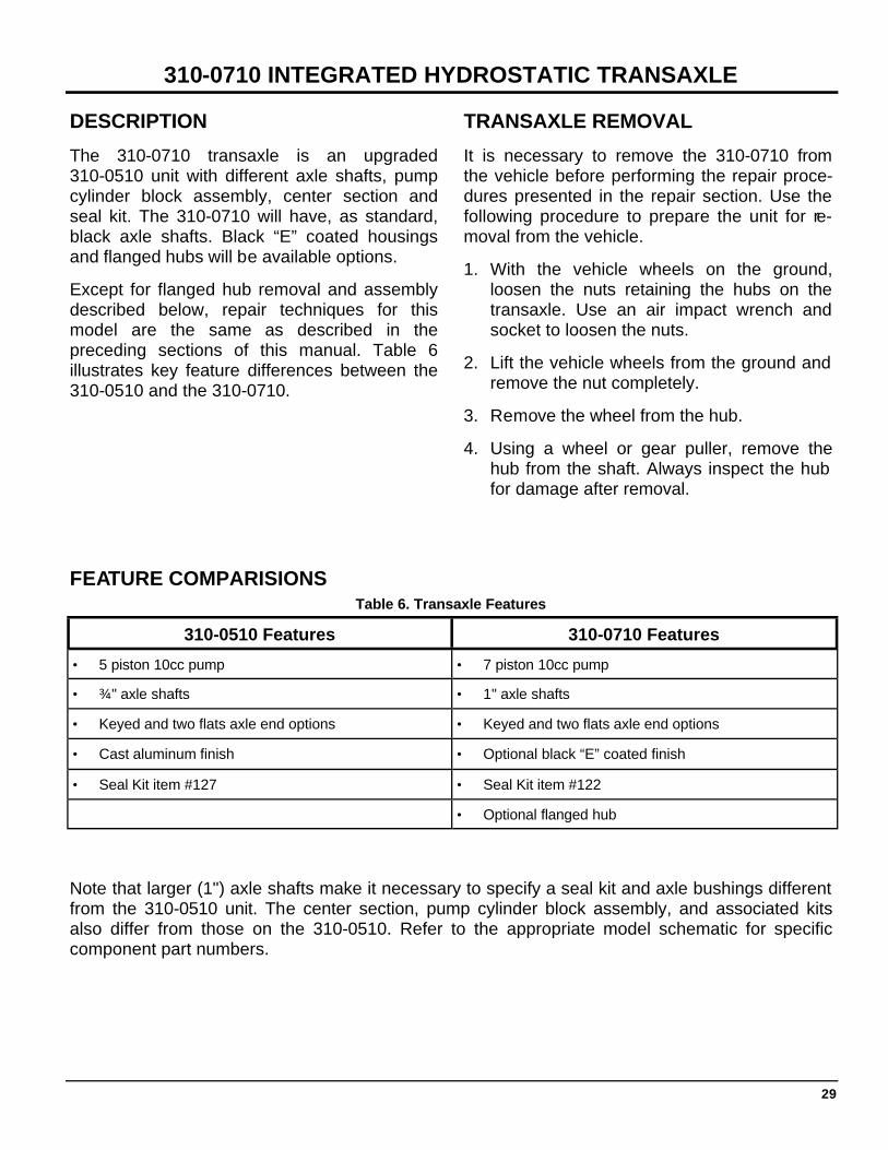
The 310-0710 transaxle is an upgraded 310-0510 unit with different axle shafts, pump cylinder block assembly, center section and seal kit. The 310-0710 will have, as standard, black axle shafts. Black “E” coated housings and flanged hubs will be available options.
Except for flanged hub removal and assembly described below, repair techniques for this model are the same as described in the preceding sections of this manual. Table 6 illustrates key feature differences between the 310-0510 and the 310-0710.
TRANSAXLE REMOVAL
It is necessary to remove the 310-0710 from the vehicle before performing the repair proce-dures presented in the repair section. Use the following procedure to prepare the unit for re-moval from the vehicle.
1. With the vehicle wheels on the ground, loosen the nuts retaining the hubs on the transaxle. Use an air impact wrench and socket to loosen the nuts.
2. Lift the vehicle wheels from the ground and remove the nut completely.
3. Remove the wheel from the hub.
4. Using a wheel or gear puller, remove the hub from the shaft. Always inspect the hub for damage after removal.
310-0510 Features 310-0710 Features
• 5 piston 10cc pump • 7 piston 10cc pump
• ¾" axle shafts • 1" axle shafts
• Keyed and two flats axle end options • Keyed and two flats axle end options
• Cast aluminum finish • Optional black “E” coated finish
• Seal Kit item #127 • Seal Kit item #122
• Optional flanged hub
Table 6. Transaxle Features
Note that larger (1") axle shafts make it necessary to specify a seal kit and axle bushings different from the 310-0510 unit. The center section, pump cylinder block assembly, and associated kits also differ from those on the 310-0510. Refer to the appropriate model schematic for specific component part numbers.
FEATURE COMPARISIONS
310-0510 IHT 30
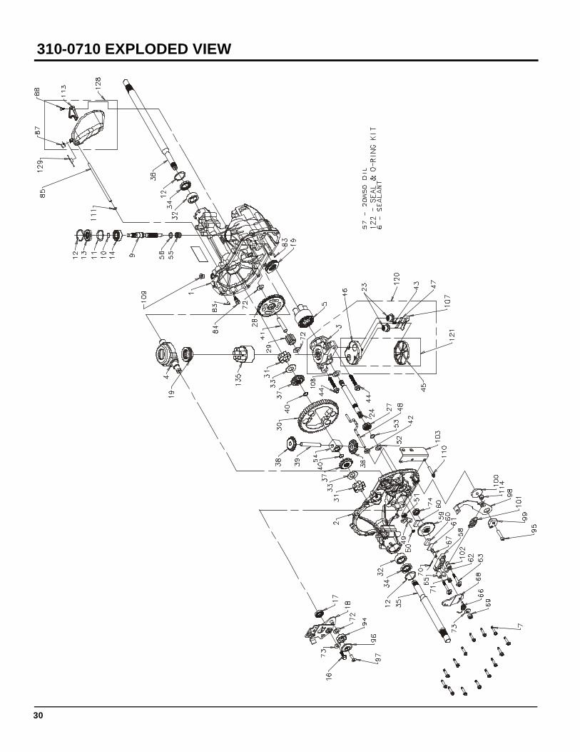
310-0710 EXPLODED VIEW
310-0510 IHT 31
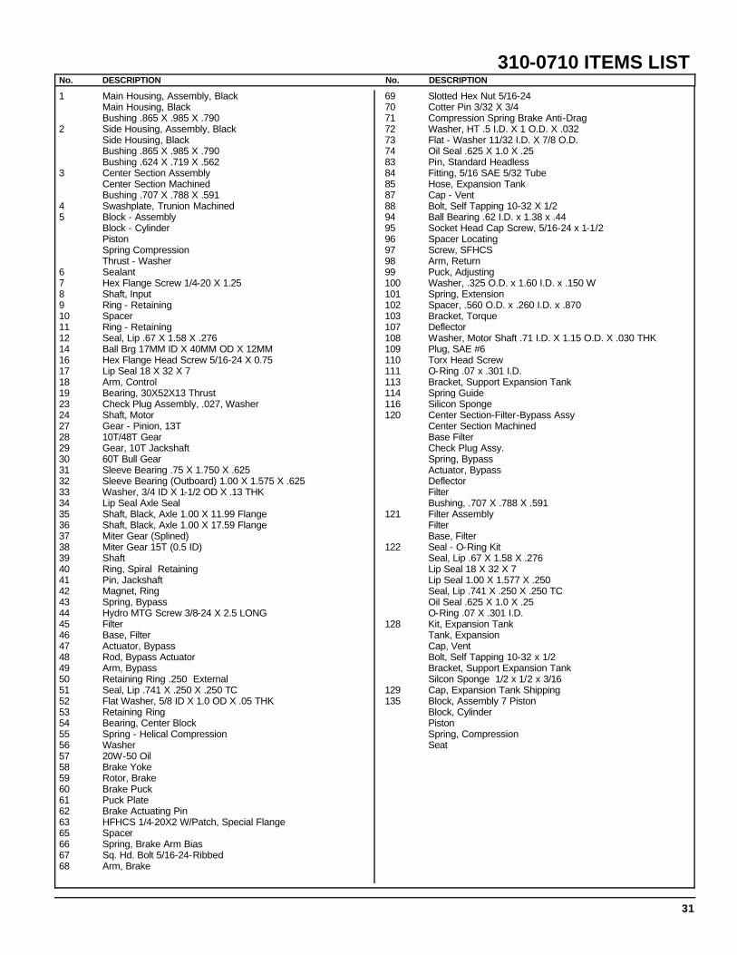
No. DESCRIPTION No. DESCRIPTION
1 Main Housing, Assembly, Black Main Housing, Black Bushing .865 X .985 X .790 2 Side Housing, Assembly, Black
Side Housing, Black Bushing .865 X .985 X .790 Bushing .624 X .719 X .562
3 Center Section Assembly Center Section Machined Bushing .707 X .788 X .591
4 Swashplate, Trunion Machined 5 Block - Assembly
Block - Cylinder Piston Spring Compression Thrust - Washer
6 Sealant 7 Hex Flange Screw 1/4-20 X 1.25 8 Shaft, Input 9 Ring - Retaining 10 Spacer 11 Ring - Retaining 12 Seal, Lip .67 X 1.58 X .276 14 Ball Brg 17MM ID X 40MM OD X 12MM 16 Hex Flange Head Screw 5/16-24 X 0.75 17 Lip Seal 18 X 32 X 7 18 Arm, Control 19 Bearing, 30X52X13 Thrust 23 Check Plug Assembly, .027, Washer 24 Shaft, Motor 27 Gear - Pinion, 13T 28 10T/48T Gear 29 Gear, 10T Jackshaft 30 60T Bull Gear 31 Sleeve Bearing .75 X 1.750 X .625 32 Sleeve Bearing (Outboard) 1.00 X 1.575 X .625 33 Washer, 3/4 ID X 1-1/2 OD X .13 THK 34 Lip Seal Axle Seal 35 Shaft, Black, Axle 1.00 X 11.99 Flange 36 Shaft, Black, Axle 1.00 X 17.59 Flange 37 Miter Gear (Splined) 38 Miter Gear 15T (0.5 ID) 39 Shaft 40 Ring, Spiral Retaining 41 Pin, Jackshaft 42 Magnet, Ring 43 Spring, Bypass 44 Hydro MTG Screw 3/8-24 X 2.5 LONG 45 Filter 46 Base, Filter 47 Actuator, Bypass 48 Rod, Bypass Actuator 49 Arm, Bypass 50 Retaining Ring .250 External 51 Seal, Lip .741 X .250 X .250 TC 52 Flat Washer, 5/8 ID X 1.0 OD X .05 THK 53 Retaining Ring 54 Bearing, Center Block 55 Spring - Helical Compression 56 Washer 57 20W-50 Oil 58 Brake Yoke 59 Rotor, Brake 60 Brake Puck 61 Puck Plate 62 Brake Actuating Pin 63 HFHCS 1/4-20X2 W/Patch, Special Flange 65 Spacer 66 Spring, Brake Arm Bias 67 Sq. Hd. Bolt 5/16-24-Ribbed 68 Arm, Brake
69 Slotted Hex Nut 5/16-24 70 Cotter Pin 3/32 X 3/4 71 Compression Spring Brake Anti-Drag 72 Washer, HT .5 I.D. X 1 O.D. X .032 73 Flat - Washer 11/32 I.D. X 7/8 O.D. 74 Oil Seal .625 X 1.0 X .25 83 Pin, Standard Headless 84 Fitting, 5/16 SAE 5/32 Tube 85 Hose, Expansion Tank 87 Cap - Vent 88 Bolt, Self Tapping 10-32 X 1/2 94 Ball Bearing .62 I.D. x 1.38 x .44 95 Socket Head Cap Screw, 5/16-24 x 1-1/2 96 Spacer Locating 97 Screw, SFHCS 98 Arm, Return 99 Puck, Adjusting 100 Washer, .325 O.D. x 1.60 I.D. x .150 W 101 Spring, Extension 102 Spacer, .560 O.D. x .260 I.D. x .870 103 Bracket, Torque 107 Deflector 108 Washer, Motor Shaft .71 I.D. X 1.15 O.D. X .030 THK 109 Plug, SAE #6 110 Torx Head Screw 111 O-Ring .07 x .301 I.D. 113 Bracket, Support Expansion Tank 114 Spring Guide 116 Silicon Sponge 120 Center Section-Filter-Bypass Assy Center Section Machined Base Filter Check Plug Assy. Spring, Bypass Actuator, Bypass Deflector Filter Bushing, .707 X .788 X .591 121 Filter Assembly Filter Base, Filter 122 Seal - O-Ring Kit Seal, Lip .67 X 1.58 X .276 Lip Seal 18 X 32 X 7 Lip Seal 1.00 X 1.577 X .250 Seal, Lip .741 X .250 X .250 TC Oil Seal .625 X 1.0 X .25 O-Ring .07 X .301 I.D. 128 Kit, Expansion Tank Tank, Expansion Cap, Vent Bolt, Self Tapping 10-32 x 1/2 Bracket, Support Expansion Tank Silcon Sponge 1/2 x 1/2 x 3/16 129 Cap, Expansion Tank Shipping 135 Block, Assembly 7 Piston Block, Cylinder Piston Spring, Compression Seat
310-0710 ITEMS LIST
310-0510 IHT 32
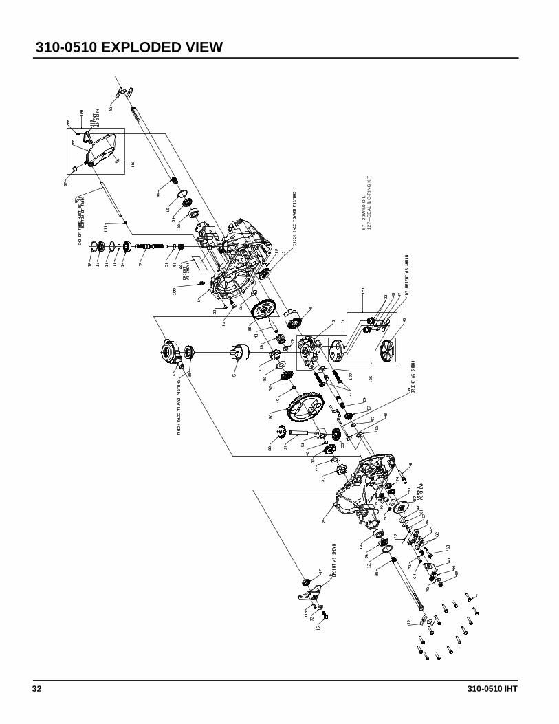
310-0510 EXPLODED VIEW
57—
20W
-50
OIL
12
7—S
EA
L &
O-R
ING
KIT
310-0510 IHT 33
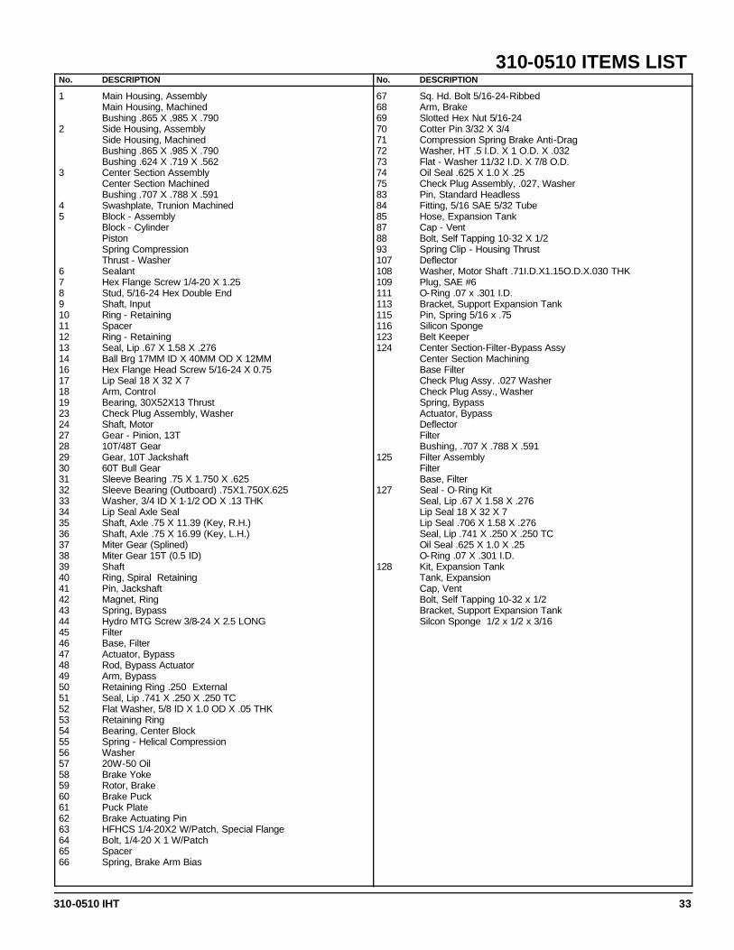
310-0510 ITEMS LIST No. DESCRIPTION No. DESCRIPTION
1 Main Housing, Assembly Main Housing, Machined Bushing .865 X .985 X .790 2 Side Housing, Assembly
Side Housing, Machined Bushing .865 X .985 X .790 Bushing .624 X .719 X .562
3 Center Section Assembly Center Section Machined Bushing .707 X .788 X .591
4 Swashplate, Trunion Machined 5 Block - Assembly
Block - Cylinder Piston Spring Compression Thrust - Washer
6 Sealant 7 Hex Flange Screw 1/4-20 X 1.25 8 Stud, 5/16-24 Hex Double End 9 Shaft, Input 10 Ring - Retaining 11 Spacer 12 Ring - Retaining 13 Seal, Lip .67 X 1.58 X .276 14 Ball Brg 17MM ID X 40MM OD X 12MM 16 Hex Flange Head Screw 5/16-24 X 0.75 17 Lip Seal 18 X 32 X 7 18 Arm, Control 19 Bearing, 30X52X13 Thrust 23 Check Plug Assembly, Washer 24 Shaft, Motor 27 Gear - Pinion, 13T 28 10T/48T Gear 29 Gear, 10T Jackshaft 30 60T Bull Gear 31 Sleeve Bearing .75 X 1.750 X .625 32 Sleeve Bearing (Outboard) .75X1.750X.625 33 Washer, 3/4 ID X 1-1/2 OD X .13 THK 34 Lip Seal Axle Seal 35 Shaft, Axle .75 X 11.39 (Key, R.H.) 36 Shaft, Axle .75 X 16.99 (Key, L.H.) 37 Miter Gear (Splined) 38 Miter Gear 15T (0.5 ID) 39 Shaft 40 Ring, Spiral Retaining 41 Pin, Jackshaft 42 Magnet, Ring 43 Spring, Bypass 44 Hydro MTG Screw 3/8-24 X 2.5 LONG 45 Filter 46 Base, Filter 47 Actuator, Bypass 48 Rod, Bypass Actuator 49 Arm, Bypass 50 Retaining Ring .250 External 51 Seal, Lip .741 X .250 X .250 TC 52 Flat Washer, 5/8 ID X 1.0 OD X .05 THK 53 Retaining Ring 54 Bearing, Center Block 55 Spring - Helical Compression 56 Washer 57 20W-50 Oil 58 Brake Yoke 59 Rotor, Brake 60 Brake Puck 61 Puck Plate 62 Brake Actuating Pin 63 HFHCS 1/4-20X2 W/Patch, Special Flange 64 Bolt, 1/4-20 X 1 W/Patch 65 Spacer 66 Spring, Brake Arm Bias
67 Sq. Hd. Bolt 5/16-24-Ribbed 68 Arm, Brake 69 Slotted Hex Nut 5/16-24 70 Cotter Pin 3/32 X 3/4 71 Compression Spring Brake Anti-Drag 72 Washer, HT .5 I.D. X 1 O.D. X .032 73 Flat - Washer 11/32 I.D. X 7/8 O.D. 74 Oil Seal .625 X 1.0 X .25 75 Check Plug Assembly, .027, Washer 83 Pin, Standard Headless 84 Fitting, 5/16 SAE 5/32 Tube 85 Hose, Expansion Tank 87 Cap - Vent 88 Bolt, Self Tapping 10-32 X 1/2 93 Spring Clip - Housing Thrust 107 Deflector 108 Washer, Motor Shaft .71I.D.X1.15O.D.X.030 THK 109 Plug, SAE #6 111 O-Ring .07 x .301 I.D. 113 Bracket, Support Expansion Tank 115 Pin, Spring 5/16 x .75 116 Silicon Sponge 123 Belt Keeper 124 Center Section-Filter-Bypass Assy Center Section Machining Base Filter Check Plug Assy. .027 Washer Check Plug Assy., Washer Spring, Bypass Actuator, Bypass Deflector Filter Bushing, .707 X .788 X .591 125 Filter Assembly
Filter Base, Filter
127 Seal - O-Ring Kit Seal, Lip .67 X 1.58 X .276 Lip Seal 18 X 32 X 7 Lip Seal .706 X 1.58 X .276 Seal, Lip .741 X .250 X .250 TC Oil Seal .625 X 1.0 X .25 O-Ring .07 X .301 I.D.
128 Kit, Expansion Tank Tank, Expansion Cap, Vent Bolt, Self Tapping 10-32 x 1/2 Bracket, Support Expansion Tank Silcon Sponge 1/2 x 1/2 x 3/16
310-0510 IHT 34
GLOSSARY OF TERMS
Axial Piston: Type of design for hydraulic motors and pumps in which the pistons are arranged parallel with the spindle (input or output shaft). Bantam Duty: A descriptive term relating to the product capacity (meaning: light duty). Bypass Valve: A valve whose primary function is to open a path for the fluid to bypass the motor or pump. Also referred to occasionally as the freewheel valve or dump valve. Case Drain Line (Return Line): A line returning fluid from the component housing to the reservoir. Cavitation: A concentrated gaseous condition within the fluid causing the rapid implosion of a gaseous bubble. Center Section: A device which acts as the valve body and manifold of the transmission. Charge Pump: A device which supplies replenishing fluid to the fluid power system (closed loop). Charge Pressure: The pressure at which replenishing fluid is forced into a fluid power system. Charge Relief Valve: A pressure control valve whose primary function is to limit pressure in the charge circuit. Check Valve: A valve whose primary function is to restrict flow in one direction. Closed Loop: A sealed and uninterrupted circulating path for fluid flow from the pump to the motor and back. Decay Rate: The ratio of pressure decay over time. End Cap: See “Center Section” Entrained Air: A mechanical mixture of air bubbles having a tendency to separate from the liquid phase. Gerotor: A positive displacement pump frequently used as a charge pump. Hydraulic Motor: A device which converts hydraulic fluid power into mechanical force and motion by transfer of flow under pressure. Hydraulic Pump: A device which converts mechanical force and motion into hydraulic fluid power by producing flow. Hydrostatic Pump: See “Hydraulic Pump”
310-0510 IHT 35
GLOSSARY OF TERMS
Hydrostatic Transaxle: A multi-component assembly including a gear case and a hydrostatic transmission. Hydrostatic Transmission: The combination of a hydraulic pump and motor in one housing to form a device for the control and transference of power. Inlet Line: A supply line to the pump. Integrated Hydrostatic Transaxle (IHT): The combination of a hydrostatic transmission and gear case in one housing to form a complete transaxle. Manifold: A conductor which provides multiple connection ports. Neutral: Typically described as a condition in which fluid flow and system pressure is below that which is required to turn the output shaft of the motor. Pressure Decay: A falling pressure. Priming: The filling of the charge circuit and closed loop of the fluid power system during start up, frequently achieved by pressurizing the fluid in the inlet line. Purging: The act of replacing air with fluid in a fluid power system by forcing fluid into all of the components and allowing the air a path of escape. Rated Flow: The maximum flow that the power supply system is capable of maintaining at a spe-cific operating pressure. Scoring: Scratches in the direction of motion of mechanical parts caused by abrasive contami-nants. Swash Plate: A mechanical device used to control the displacement of the pump pistons in a fluid power system. System Charge Check Valve: A valve controlling the replenishing flow of fluid from a charge cir-cuit to the closed loop in a fluid power system. System Pressure: The pressure which overcomes the total resistance in a system, including all losses. Valve: A device which controls fluid flow direction, pressure, or flow rate. Variable Displacement Pump: A pump in which the displacement per cycle can be varied. Volumetric Displacement: The volume for one revolution.
310-0510 IHT 36
© 2001 HYDRO-GEAR Printed in U.S.A.